
Hapi MKII - Audio recorder Merging - Free user manual and instructions
Find the device manual for free Hapi MKII Merging in PDF.


| Product Type | Audio Recorder / Network Audio Interface |
| Brand | Merging Technologies |
| Model | Hapi MKII |
| Dimensions (1U rack mount) | 483 x 320 x 44 mm (19 x 12.6 x 1.7 in) |
| Weight | 4.5 kg / 10 lbs |
| Power Supply | AC 100-240V, 50-60 Hz or DC 10-14V (optional PSU) |
| Power Consumption | < 30 Watts (fully loaded with phantom power) |
| Maximum I/O Channels | 88 inputs / 90 outputs @ 1FS (with optional cards) |
| Networking | RAVENNA / AES67 with dual Gigabit Ethernet (ST2022-7 redundancy and switch mode) |
| Built-in I/O | 8x AES/EBU (DB25), 8x ADAT or 2x SPDIF (TOSLINK), Word Clock, Video Ref, LTC |
| Expansion Slots | 2 slots for AD, DA, ADA, MADI, or PT64 modules |
| Front Panel Display | 160x128 pixel OLED with rotary encoder control |
| Headphone Output | Two 6.35mm/3.5mm TRS, up to 200mW, DSD support, per-channel trim |
| Sample Rates | 44.1 kHz to 192 kHz (standard); up to DXD/DSD256 (Premium modules) |
| Latency | Near-zero (< 1 ms) from input to output |
| Remote Control | Web browser, ANEMAN, MT Discovery, and Pro Tools integration |
| Mic Preamps (optional module) | Up to 8 channels with +48V, polarity, low cut, impedance switching; 136 dB dynamic range (AKDG8DP) |
| Safety Compliance | UL 1950, EN 60950, CE, FCC Class A |
| Operating Temperature | +5°C to +55°C |
| Warranty | 2 years limited (original purchaser) |
| Cleaning and Maintenance | Use a dry cloth; no user-serviceable parts inside; contact authorized service for repairs |
| Spare Parts and Repairability | Optional I/O modules (AD, DA, ADA, MADI, PT64) and power supply (PSSBU31-105) available; modules can be replaced by authorized partners |
| General Information | Modular, low-power, Swiss-designed audio interface for studio and broadcast; supports standalone or network operation |
Frequently Asked Questions - Hapi MKII Merging
User questions about Hapi MKII Merging
0 question about this device. Answer the ones you know or ask your own.
Ask a new question about this device
Download the instructions for your Audio recorder in PDF format for free! Find your manual Hapi MKII - Merging and take your electronic device back in hand. On this page are published all the documents necessary for the use of your device. Hapi MKII by Merging.
USER MANUAL Hapi MKII Merging

Hapi MKII User Manual
Contents
Hapi Warranty Information....10
Contacting Merging Technologies....10
Introduction to HAPI MKII....11
HAPI MKII - Block Diagram....13
HAPI - Optional Cards....16
IOM-H-AKDG8D / AKDG8DP 16
IOM-H-AKD8D / AKD8DP....19
IOM-H-AD8D / AD8DP - Legacy Product 22
IOM-H-DA8/DA8P (>= run 11)....25
IOM-HORUS-DA8/DA8P (< run 11) - Legacy product....27
IOM-H-ADA8S/ADA8P 31
IOM-H-ADA8 - Legacy Product....35
IOM-H-PT64....37
IOM-HAPI-MADM/MADS 41
HAPI - Cables 42
HAPI MKII Key Features 47
HAPI MKII - Modules Capabilities 50
HAPI MKII - Modules Latencies....50
Installing an additional Hapi I/O Module 51
Installing a Hapi MADI Module (MADM or MADS are optional)....52
Assembling the Rack Mount ears ....54
Installing the Merging NET-MSC-GBEX1 55
HAPI MK II - Power ON....57
HAPI MKII - OLED screen interface ....59
Hapi Menu Hierarchy....59
Screen Navigation....60
Home Screen 60
Volume Menu....61
Meters Menu....61
A/D Meters Sub-Menu (Meters)....61
D/A Meters Sub-Menu (Meters)....62
Input Levels Sub-Menu (Meters)....62
Output Levels Sub-Menu (Meters) 62
Meters Settings Menu 63
I/O Menu & Sync Sub-Menu (I/O)....63
Refs Sub-Menu (I/O) 64
Timecode Sub-Menu (I/O)....65
Status Sub-Menu (I/O)....65
PreAmp Menu....67
Setup Menu....69
Formats Menu (Setup)....69
Routing Menu (Setup)....71
Routing: Source Configuration 71
Modules Menu (Setup)....73
Headphone Menu....74
TRIM: Headphones....74
Modules: MADI Sub-Menu 75
Modules: A/D Sub-Menu 75
Modules: ADA Sub-Menu....76
Modules: D/A Sub-Menu 76
TRIM: DA....77
Modules: Loopback (hidden menu, available only for debug use)....78
System (Setup): 79
Network Menu (Setup)......80
Info (Setup): 81
ERROR Menu 81
EXIT Menu....82
HAPI MKII - Web Control Access....83
Installing and accessing the Hapi Control interface remotely....83
Identify Me - Device Location 92
HAPI MKII embedded User Manual....93
HAPI & HORUS Setup Examples 94
IOM-H-PT64 & Digidesign HDIO Setup....100
Manage Mic PREs from Pro Tools....101
Pro Tools on PC Horus/Hapi....102
Use Horus-HAPI MIDI din....104
HAPI MKII - Firmware Update Procedure....106
HAPI - Troubleshooting....110
Hapi on screen Error Report....110
How to provide Merging Support with a Hapi MKII Debug Report file 112
Firewall and Antivirus....112
FOR MORE INFORMATION ....113
IMPORTANT SAFETY AND INSTALLATION INSTRUCTION SAVE THESE INSTRUCTIONS
INSTRUCTIONS PERTAINING TO RISK OF FIRE, ELECTRIC SHOCK, OR INJURY TO PERSONS
WARNING – when using electric products, basic precautions should be followed, including the following:
- Read all of the safety and installations instructions and explanation of graphic symbols before using the product.
- The product must be grounded otherwise it could malfunction or breakdown. Grounding provides a path of least resistance or electric current to reduce the risk of electric shock. This product is equipped with a power supply cord having an equipment-grounding conductor and a grounding plug. The plug must be plugged into an appropriate outlet which is properly installed and grounded in accordance with all local codes and ordinances.
DANGER – Improper connection of the equipment-grounding can result in a risk of electric shock. Do not modify the plug provided with the product – if it will not fit the outlet have a proper outlet installed by a qualified electrician. Do not use an adapter that defeats the function of the equipment-grounding conductor. If you are in doubt as to whether the product is properly grounded, check with a qualified serviceman or electrician.
- Do not use this product near water – for example, near a bathtub, washbowl, kitchen sink, in a wet basement, or near a swimming pool, or the like.
- This product should only be used with a stand or cart that is recommended by the manufacture.
- This product, either alone or in combination with an amplifier and speakers or headphones, may be capable of producing sound levels that could cause permanent hearing loss. Do not operate at a high volume level or at a level that is uncomfortable. If you experience any hearing loss or ringing in the ears, you should consult an audiologist.
- The product should be located so that its location or position does not interfere with its proper ventilation.
- The product should be located away from heat sources such as radiators, heat registers, or other products that produce heat.
- The product should be connected to a power supply only of the type described in the operating instructions or as marked on the product.
- The power-supply cord of the product should be unplugged from the outlet when left unused for a long period of time. When unplugging the power supply, do not pull on the cord, but grasp it by the plug.
-
Care should be taken so that objects do not fall and liquids are not spilled into the enclosure through openings.
-
The product should be serviced by qualified service personnel when: A. The power supply cord or plug has been damaged. Objects have fallen, or liquid has spilled into the product, or C. The product has been exposed to rain, or D. The product does not appear to be operating normally or exhibits a marked change in performance, or E. The product has been dropped, or the enclosure damaged.
- Do not attempt to service the product beyond that described in the user maintenance instructions. All other servicing should be referred to qualified service personnel.
- WARNING - Do not place objects on the power supply cord, or place the product in a position where anyone could trip over, walk on, or roll anything over cords of any type. Do not allow the product to rest on or be installed over cords of any type. Improper installations of this type create the possibility of a fire hazard and/or personal injury.

The lightning flash with arrowhead symbol, within an equilateral triangle, is intended to alert the user to the presence of uninsulated "dangerous voltage" the product's enclosure that may be of sufficient magnitude to constitute a risketric shock to persons.

The exclamation point within an equilateral triangle is intended to alert the user to the presence of important operating and maintenance (servicing) instructions literature accompanying the product.
No part of this documentation may be reproduced in any form whatsoever or be stored in any data retrieval system without prior written permission of the copyright owners.
This documentation is supplied on an as-is basis. Information contained within this documentation is subject to change at any time without notice and must not be relied upon. All company and product names are TM or Registered Trademarks of their respective owners. Windows 7 and Windows 10 are a trademark of Microsoft Corporation.
Merging Technologies makes no warranties express or implied regarding the Hapi embedded software, its quality, performance, merchantability or fitness for a particular purpose. The software is supplied “as is” you, the purchaser, are assuming the entire risk of the results of using this Merging Technologies software.
In no circumstances will Merging Technologies, its owners, directors, officers, employees or agents be liable to you for any consequential, incidental or indirect loss or damages including loss of time, loss of business, loss of profits, loss of data or similar resulting from the use of or inability to use the Merging Technologies hardware and or software or for any defect in the hardware software or documentation.
© Copyright Merging Technologies Inc. 2022. All rights reserved.
IMPORTANT NOTICE:
Please read the following information very carefully before attempting any installation. Failure to comply with the precise instructions may result in damage to your Merging hardware. Please read this entire section of the manual carefully before installation.
STATIC DANGER NOTICE:
Please note that the Hapi contains delicate electronic components that can be damaged or even destroyed when exposed to static electricity. Take all necessary precautions not to discharge static electricity when touching any of the Hapi connectors.
Product Regulatory Compliance
The Merging Hapi Network Converter is designed and tested to meet the standards and regulations listed in the following sections.
Product Safety Compliance
Hapi complies with the following safety requirements:
- UL 1950 – CSA 950 (US/Canada).
• EN 60 950 (European Union).
• IEC 60 950 (International). - CE – Low Voltage Directive (73/23/EEC) (European Limits).
• EMKO-TSE (74-SEC) 207/94 (Nordics).
Product EMC Compliance
The system has been tested and verified to comply with the following EMC regulations:
• FCC (Class A Verification) – Radiated and Conducted Emissions (USA).
• CISPR 22, 3rd Edition (Class A) – Radiated and Conducted Emissions (International).
• EN45022 (Class A) – Radiated and Conducted Emissions (European Union).
• EN45024 (Immunity) (European Union).
• EN6100-3-2 & -3 (Power Harmonics and Fluctuation and Flicker).
• CE – EMC Directive (89/33/EEC) (European Union).
Electromagnetic Compatibility Notices
This device complies with Part 15 of the FCC Rules. Operation is subject to the following two conditions: (1) this device may not cause harmful interference and (2), this device must accept any interference received, including interference that may cause undesired operation.
This equipment has been tested and found to comply with the limits for a Class A digital device, pursuant to Part 15 of the FCC Rules. These limits are designed to provide reasonable protection against harmful interference in a residential installation. This equipment generates, uses, and can radiate radio frequency energy and, if not installed and used in accordance with the instructions, may cause harmful interference to radio communications. However, there is no guarantee that interference will not occur in a particular installation. If this equipment does cause harmful interference to radio or television reception, which can be determined by turning the equipment off and on, the user is encouraged to try to correct the interference by one or more of the following measures:
- Reorient or relocate the receiving antenna.
- Increase the separation between the equipment and the receiver.
- Connect the equipment to an outlet on a circuit other than the one to which the receiver is connected.
- Consult the dealer or an experienced radio/TV technician for help.
Any changes or modifications not expressly approved by the grantee of this device could void the user's authority to operate the equipment. The customer is responsible for ensuring compliance of the modified product.
Only peripherals (computer input/output devices, Ethernet switches, terminals, printers, etc.) that comply with FCC Class B limits may be attached to this computer product. Operation with noncompliant peripherals is likely to result in interference to radio and TV reception.
All cables used to connect to peripherals must be shielded and grounded. Operation with cables, connected to peripherals that are not shielded and grounded, may result in interference to radio and TV reception.
Environmental Limits
System Office Environment Parameter Limits
Operating Temperature +5 degrees C to +55 degrees C with the maximum rate of change not to exceed 10 degrees C per hour.
Non-Operating Temperature -40 degrees C to +70 degrees C
Non-Operating Humidity 95%, non-condensing @ 30 degrees C
Operating Shock No errors with a half sine wave shock of 2G (with 11-millisecond duration).
Package Shock Operational after a free fall, 60 cm depending on the weight.
ESD 15kV per Merging Environmental Test Specification
EU Declaration of Conformity (DoC)
Merging Technologies S.A.
Le Verney 4
CH-1070 Puidoux
Switzerland
declares that the DoC is issued under its sole responsibility that the product:
Model: Hapi MkII
Type: IOC-HAPI-MKII
with the included component:
Power supply: PSSBU31-105
and all variations specified in the annex are in conformity with the provisions of the following EU directive(s) (including all applicable amendments); and are designed and manufactured with application of the harmonized standards.
The history of this document is listed on the last page.

Puidoux, March 22, 2021
Claude Cellier, CEO
Applied directives and standards:
| The devices: IOC-HAPI-MKII comply with the following: | |||
| Pos.-No. | Document | Short description | Issued / Version |
| 3010 | 2014/35/EU | Low Voltage Directive 2014/35/EUElectrical Safety (publication references OJEU L 96, 29.03.2014, p.357-374) | 2014-02 |
| 3301 | EN 62368-1 | Audio/video, information and communication technology equipment - Part 1: Safety requirements | 2014 + AC:2015 + A11:2017 |
| 7551 | No. 2019/1782 | EU-Regulation for External Power Supplies (Energy Efficiency) (publication references OJEU L 272, 25.10.2019, p. 95-106) | 2020-04 |
| 7801 | 2011/65/EU | RoHS Directive 2011/65/EURestriction of the use of certain hazardous substance (publication references OJ L 174, 01.07.2011, p.88-110) amended by (EU) 2015/863) | 2011-06 with all amendments |
| 7820 | EN IEC 63000 | Technical documentation for the assessment of electrical and electronic products with respect to the restriction of hazardous substances | 2018-12 |
Document History
| Revision Date: | Revision Description | Remarks |
| 2020-03-22 | First version | |
Hapi Warranty Information
This product is warranted to be free of defects in materials and workmanship for a period of two years from the date of purchase. Merging Technologies, Inc. extends this Limited Warranty to the original purchaser.
In the event of a defect or failure to confirm to this Limited warranty, Merging Technologies, Inc. will repair or replace the product without charge within sixty (60) days. In order to make a claim under this limited warranty, the purchaser must notify Merging Technologies, Inc. or their representative in writing, of the product failure. In this limited warranty the customer must upon Merging Technologies, Inc. request, return the product to the place of purchase, or other local designation, for the necessary repairs to be performed. If the consumer is not satisfied with the repair, Merging Technologies, Inc. will have the option to either attempt a further repair, or refund the purchase price.
This warranty does not cover: (1) Products which have been subject to misuse, abuse, accident, physical damage, neglect, exposure to fire, water or excessive changes in the climate or temperature, or operation outside maximum rating. (2) Products on which warranty stickers or product serial numbers have been removed, altered or rendered illegible. (3) The cost of installations, removal or reinstallation. (4) Damages caused to any other products. (5) Do not attempt to service the equipment. There are no user serviceable parts inside*. Please refer all servicing to an authorized Merging sales partner. Any attempt to service the equipment will expose you to a risk of electric shock, and will void the manufacturer's warranty.
* Replacing or adding a AD, DA or MADI module and adjusting the DA module dip switch of legacy DA (output) is permitted under the supervision of a Merging sales partner. Any other modification will void the Hapi warranty.
Contacting Merging Technologies
International Office:
Merging Technologies S.A.
Le Verney 4
CH-1070 Puidoux
Switzerland
Phone: +41 21 946 0444
Fax: +41 21 946 0445
USA:
Merging USA (Independent Audio)
43 Deerfield Road
Portland,
ME 04101-1805
United States of America
For all documentation inquiries or suggestions for improvement:
www.merging.com
© 2021 All rights reserved. Merging Technologies, Horus and Hapi are registered Trademarks of Merging technologies SA.
Product features and specifications are subject to change without notice.
Merging Technologies SA shall not be liable for technical or editorial errors contained herein, nor for incidental or consequential damages resulting from the furnishing, performance or use of this manual.
Introduction to HAPI MKII
Modular by Design
Hapi, the son of Horus. Born from the most flexible and sonically transparent audio interface and providing the same RAVENNA / AES67 connectivity as its father, Hapi is both the perfect primary interface for smaller systems as well as the ultimate accessory for a system using Horus where control room I/O is required. Hapi was designed to give its users an Audio I/O channels flexibility while offering an unprecedented level of quality in such a small form factor.
Providing as standard; 8 channels of AES- EBU I/O plus 8 ADAT or 2 SPDIF I/O (on TOSLINK) and 2 Network interfaces 2 slots for AD8D/AD8P, DA8/DA8P, MADI or PT64 option cards. Once the Hapi is fully loaded with option cards, it is capable of achieving 88 inputs and 90 outputs @ 1FS There are indeed 2 more output channels than input channels, including the Stereo Headphone Monitoring.
Route Signal Anywhere
Hapi has been designed so that any input can be routed to any number of outputs as required simultaneously. With comprehensive routing pages accessible both locally on the touchscreen and by remote access using a standard web browser, Hapi is the answer to signal flow management in your studio.
Green Built
For environmentally-conscious users, Hapi has been designed meticulously in order to keep power consumption at an incredible minimum. A fully loaded Hapi running all channels of phantom power will only draw about 30W, making it more affordable to run than your kitchen lights.
HAPI MKII Key Features
- Up to 88 inputs and 90 outputs @1FS
- 8x AES/EBU + 8x ADAT or 2x SPDIF (Optical)
- Standard modules support 44.1kHz to 192kHz and Premium up to DXD/DSD256.
- Signal routing from any input to any combination of outputs
- RAVENNA/AES67 Compatible (Hapi MKII supports Network redundancy and Network Switch mode)
- Browser-based remote access using any web enabled device
• AC or DC power supply options - Modular design for additional analog and Digital I/O
- Near-zero latency from in to out (<1ms)
- Main rotary control button
• ST2022-7 Support (Seamless Protection Switching)
• Network Switch mode support (allowing daisy chain for an extra network device)
• Additional Roll Off filters
• Per channel DA Trims level and polarity support - Per channel Headphones Trims level and polarity support
- Routing support with per channel support
- Mastering grade Headphone Amp
- Powerful Headphone Amp suitable for ultra-low to very high impedance headphones.
• Headphones DSD volume support (DSD64, DSD128, DSD256)
• Headphones DSD256 support - OLED display for local control access
RAVENNA
The Hapi has been designed so that the MADI, AES, SPDIF/ADAT, PT64 and Analog modules can all feed into or take their sources from the network over RAVENNA streams, providing up to 88 channels of I/O @ 1FS over a single CAT5e or CAT6 cable to any other RAVENNA devices on the network.
The RAVENNA connection on the Hapi allows for not only audio, but also control and sync information to flow through as well. Send Timecodes and Wordclock directly to the Hapi unit over the same network as your audio. The RAVENNA port even provides for remote control access to the configuration and entire routing of the unit itself! Support for: LTC/Video Ref/WCK
RAVENNA is a layer 3 IP based protocol. In environments where existing networks are already in place, RAVENNA subnets can slip right into place with no additional outlay. In laymen's terms, this means that you can connect your Hapi to a properly configured network exactly as you would your PC or Mac, with no additional technology required.
RAVENNA is a “mission critical” protocol, meaning that is has been designed to ensure immensely low jitter rates and latencies (sub-millisecond) and ensures that every single sample gets to where it needs to go without fail. Hapi MKII provides a secondary (RJ45), redundant RAVENNA connection for uninterrupted use, even when a network connection fails, it can also be used in switch mode.
Refer to the RAVENNA User Guide and the MassCore-RAVENNA Configuration Guide for more details
HAPI MKII - Block Diagram
Hapi MkII hardware block diagram
![graph TD A["Ultra low noise oscillator 33.3333MHz"] --> B["Power supply"] C["90-230 VAC / 50-60Hz"] --> B D["10-14 VDC (optional)"] --> B E["Gigabit Ethernet switch"] --> F["RAVENNA Acceleration"] F --> G["Sync module"] G --> H["Router / PeakMeter"] I["Ultra low noise oscillator 33.3333MHz"] --> J["…](/content/2026/05/903531/images/edf1948f7e51f42a49defce60b5f2c8cfcb4a1584f152a77d68a37d784a652b0.jpg)
HAPI MKII - Hardware
FRONT PANEL

BACK PANEL

HAPI UNIT

HAPI SCHEMATIC IMAGES
Front Panel

Back Panel

HAPI BASE UNIT
IOC-HAPI Specifications
Case Material Powder Coated Steel
Front Panel Material Brushed Aluminum
Weight (excluding redundant PS) 4.5 kg / 10 lbs
Dimensions (1U rack mounting) 483 x 320 x 44 mm
Voltage (AC)
Voltage (DC) (option IOC-HAPI-PSR) 10-14VDC
Power Consumption (Max) < 30 Watts
Front Panel TFT size/resolution OLED (160x128 px)
100V–240VAC, 50–60 Hz
Headphone Monitor Jacks
Headphone Jack 1&2 6.35mm ( 1/4 ) & 3.5mm TRS Female Stereo
Dynamic Range (A-weighted, typ.) High / Low < -118 dB
Max output Level High / Low 15 dBu / 7.3 dBu (load 600/16 Ω)
Max output Power 2 x 200 mW (load 16 Ω)
Frequency response +0/-0.2dB @ fs = 48 kHz 6 Hz - 22 kHz
Frequency response +0/-3dB @ fs = 96 kHz 2 Hz - 44.2 kHz
Frequency response +0/-3dB @ fs = 192 kHz 2 Hz - 88.1 kHz
Output Impedance 20Ω
THD+N 1 kHz @ 0 dBFS High / Low < -106 dB (0.0005%)
Attenuation Range (Software controlled) - ∞ to 12 dB
Gain Step/Precision 0.5 dB / ±0.05 dB
DXD Support Native
LTC In & Out (via "Sync" Cable) Balanced XLR
Video Reference In (via "Sync" Cable) BNC
Word Clock Input (Switchable 75 Ω Termination) BNC, 0.5Vp-p min
Word Clock Output (Zout = 35 Ω) BNC, 5Vp-p
Maximum supported deviation +/-1000ppm
RAVENNA module
RAVENNA Primary / Secondary (GbE) RJ45
AES-EBU module
AES type/pinout DB-25 / AES59 (Tascam Dig.)
AES i/o Grounded and transformer coupled
Output Impedance 110 Ω
MADI module
MADI types (Coaxial / Optical) BNC / SC
Output Impedance 75 Ω
ADAT/SPDIF module
ADAT/SPDIF Optical Toslink
Software Specifications
RAVENNA MassCore Driver
Pyramix v12.0 or Higher / Win7 or Win10 64bit
Windows Driver/OS ASIO 2.2 / Win7 or Win10 64bit
Mac Driver/OS CoreAudio / MacOS 10.13 or higher
HAPI - Optional Cards
IOM-H-AKDG8D / AKDG8DP
These remotely controlled Mic/Line Input cards are 3rd generation Dual Gain topology designs, inspired from the Anubis outstanding Preamps, that show zero tolerance to any compromise on the audio quality.
A new benchmark in analog circuitry design, and provide additionally a Line level post Mic-pre "Direct Out" output.
Available in models that work up to 192kHz (AKDG8D) and DXD/DSD256 (AKDG8DP)

IOM-H-AKDG8D / AKDG8DP Key Features
- 8 x exceptionally transparent, Swiss designed pre-amplifiers
- Remote/Local switch to Line Level on a per channel basis
- Completely accessible remotely for all parameter changes
- Phantom Power/Polarity Invert/Low Cut/Impedance switchable per channel
- Removes the need for DI boxes
- Allows build-in Mic splitting variants
• Dynamic range of 136dB (A-weighted, typ)
• Auto-mute circuitry for "no-pop" power cycling
IOM-H-AKDG8D / AKD8GDP Mic Pre-Amp + ADC
Mic Pre Max Input (Mic+Pad / Mic / Boost) +24 dBu / +12 dBu / +0 dBu
Mic Pre Max Input (Pad On; Pad Off) > 3 kΩ; 10.4 kΩ
Input Impedance (ZIo; ZHi) > 3 kΩ; 10.4 kΩ
Dynamic Range (flat 20 Hz-20 kHz) > 134 dB
Dynamic Range (A-weighted, typ) 136 dB
Gain Range (software controlled) 0 dB to +66 dB
Gain Precision ±0.2 dB
Gain Step 0.5 dB
THD+N Pre + A/D (20 Hz-20 kHz) @ -2 dBFS -110 dB (0.00031 %)/-112 dB (0.00025 %)
Interchannel Crosstalk @ 1kHz, typ. <-125dB
Interchannel Crosstalk @ 20Hz - 20 kHz < -100 dB
EIN @ >40 dB Gain (150Ω Source Impedance, A-weighted, typ) -128 dBu
Common Mode Rejection Rate @ 1kHz, typ. 75 dB (up to -20 dBFS)
Common Mode Rejection Rate @ 20Hz - 20 kHz > 60 / 65 dB (up to -20 dBFS)
Phantom Power (Software Switchable Per Channel) +48 Volts
Phase Reverse Switch (Software Switchable Per Channel) Yes
Low Cut filter (Software Switchable Per Channel) -12 dB/octave, 80 Hz
IOM-H-AKDG8D/ADDG8DP Line input Section

MERGING
THE NETWORKING AGE

www.merging.com/hapi
| Frequency response +0/-0.1dB @ fs = 44100 Hz | 5.7 Hz - 20.5 kHz |
| Frequency response +0/-1.0dB @ fs = 44100 Hz | 1.8 Hz - 21.0 kHz |
| Frequency response +0/-0.1dB @ fs = 96000 Hz | 5.7 Hz - 43.9 kHz |
| Frequency response +0/-1.0dB @ fs = 96000 Hz | 1.8 Hz - 45.4 kHz |
| Frequency response +0/-0.1dB @ fs = 192000 Hz | 5.7 Hz - 42.1 kHz |
| Frequency response +0/-1.0dB @ fs = 192000 Hz | 1.8 Hz - 64.7 kHz |
| Frequency response +0/-0.1dB @ fs = 384000 Hz | 5.7 Hz - 40 kHz |
| Frequency response +0/-1.0dB @ fs = 384000 Hz | 1.8 Hz - 75 kHz |
Max Line Input for 0 dBFS +24 dBu
Input Impedance 10.4 kΩ
Dynamic Range (flat 20 Hz-20 kHz), ref +24 dBu >136 dB
Dynamic Range (A-weighted, typ), ref +24 dBu 138.5 dB
THD+N Line+A/D (1 kHz) @ -2 dBFS, Typ. -106 dB (0.0005%)/-109 dB (0.00035%)
THD+N Line+A/D (20 Hz-20 kHz) @ -2 dBFS < -106 dB
Interchannel Crosstalk @ 1kHz, typ. -130 dB
Interchannel Crosstalk @ 20Hz - 20 kHz < -100 dB
Sensitivity Range for 0 dBFS (software controlled) -42 dBu to +24 dBu
Gain Precision ±0.2 dB
Gain Step 0.5 dB
Common Mode Rejection Rate @ 1kHz, typ. 75 dB (up to -20 dBFS)
Common Mode Rejection Rate @ 20Hz – 20 kHz > 65 dB (up to -20 dBFS)
Group Delay (1FS) 5/fs
Group Delay (2FS) 5/fs
Group Delay (4FS) / Premium (8FS) 6/fs / 7/fs
IOM-H-AKDG8D / AKDG8DP Direct Out Section
Max Direct Output level typ. +24 dBu / +12 dBu / +0 dBu
Output Impedance (Differential) < 100 Ω
THD+N (1 kHz) @ +10dBu < -111dB (0.00028 %)
Input Connector Pinout DB-25 / AES59 (Tascam Ana.)
Direct Output Connector Pinout DB-25 / AES59 (Tascam Ana.)
IOM-H-AKDG8D / AKDG8DP Dual preamp block diagram
IOM-H-AKDG8DS/AKDG8DP Dual PreAmp input diagram
![graph LR A["48V"] --> B["Lino"] A --> C["Mic"] A --> D["Boost"] A --> E["PreAmp"] A --> F["-2.4dB"] B --> G["Gain -14dB"] C --> H["A/D 3.2bits"] D --> I["A1 -17dB"] E --> J["A/D 32bits"] F --> K["+"] G --> L["Adderation 21dB"] H --> M["Adderation 21dB"] I --> N["Adderation 21dB"] J --> O["Adderation…](/content/2026/05/903531/images/0470760ee6265a3bb400c30a29461fe0a1a9aa1069224465a16821d78948bb35.jpg)
IOM-H-AKDG8D/AKDG8DP block diagram
Data flow in PCM on AKDG8DS/AKDG8DP cards
![graph TD A["Direct Out"] --> B["-2.4 dB"] C["Analog Input"] --> D["48V phantom power On / Off"] D --> E["Zn selector 3kΩ / 10.4kΩ"] E --> F["Pream analog gain Lhe / Mic+Pad / Mic / Mic Boost"] F --> G["A/D converter"] G --> H["32 bits"] I["FPGA"] --> J["DC remover"] J --> K["Digital gain + low cut f…](/content/2026/05/903531/images/b8ed805a863ebef9f3b70698f372f8538f66872639c803e83310933ae009c6b5.jpg)
Data flow in DSD on AKDG8DP cards
![graph TD A["Direct Out"] --> B["-2.4 dB"] C["Analog input"] --> D["48V phantom power On / Off"] D --> E["Zin selector 3kΩ / 10.4kΩ"] E --> F["Preamp analog gain Line / Mic+Pad / Mic / Mic Boost"] F --> G["A/D converter"] H["DC Remover"] --> I["Digital gain + low cut filter"] I --> J["Σ/Δ Modulator"]…](/content/2026/05/903531/images/954b2bf5ae4fdef140366f7a7c377ebdcd26f941c483bfc6aa9e4bd6c8b01bf8.jpg)
Note: The AKDG8DS/P cards do not reflect on their Direct Outs the Digital Gain values which are only applied to the local signal paths. They offer a fixed level output, and do reflect the Line/Mic/Boost respective Analog front-end gains. Which are 0 dB for Line (and Mic with PAD), 12 dB for Mic and 24 dB for Boost settings.
IOM-H-AKD8D / AKD8DP
These remotely controlled Mic/Line Input cards have set a new benchmark in analog circuitry design, and provide additionally a Line level post Mic-pre "Direct Out" output.
Available in models that work up to 192kHz (AKD8D) and DXD/DSD256 (AKD8DP)
IOM-H-AKD8D / AKD8DP Key Features
- 8 x exceptionally transparent, Swiss designed pre-amplifiers
- Remote/Local switch to Line Level on a per channel basis
- Completely accessible remotely for all parameter changes
- Phantom Power/Polarity Invert/Low Cut switchable per channel
- Removes the need for DI boxes
- Allows build-in Mic splitting variants
• Better than 120dB dynamic range
IOM-H-AKD8D / AKD8DP Mic Pre-Amp + ADC
Mic Pre Max Input (Pad On / Pad Off) +24 dBu / +13 dBu
Input Impedance (Differential, Software Switchable Per Channel) 1.9 kΩ / 10 kΩ
Input Impedance with +48V ON (Diff., Soft. Switchable Per Channel) 1.9 kΩ / 10 kΩ
Dynamic Range (A-weighted, typ.), ref +10 dBu 123.5 dB
Gain Range (software controlled) 0 dB to +66 dB
Gain Step/Precision 0.5 dB / ±0.2 dB
THD+N Pre + A/D (20 Hz-20 kHz) @ -2 dBFS (AD8/AD8P) < -110dB (0.00031%)/-111dB (0.00028%)
Interchannel Crosstalk @ 1kHz, typ. < -125 dB
EIN @ >40 dB Gain (150Ω Source Impedance, A-weighted, typ.)
Common Mode Rejection Rate (20 Hz - 20 kHz)
Phantom Power (Software Switchable Per Channel) +48V
Polarity Invert (Software Switchable Per Channel) YES
Low Cut filter (Software Switchable Per Channel) -12 dB/octave, 80 Hz
Line Input
Max Line Input for 0 dBFS +24 dBu
Input Impedance (Differential) 10 kΩ
Dynamic Range (A-weighted, typ), ref +24 dBu 124 dB
THD+N Line+A/D (20 Hz - 20 kHz) @ -10 dBFS < -110dB (0.00031%)/-111dB (0.00028%)
Interchannel Crosstalk @ 1kHz @ fullscale < -130 dB
Sensitivity Range for 0 dBFS (software controlled) -42 dBu to +24 dBu
Gain Step/Precision 0.5 dB / ±0.2 dB
Common Mode Rejection Rate (20 Hz – 20 kHz) >60 dB / >65dB (both up to 0 dBFS)
Connector Pinout DB-25 / AES59 (Tascam Ana.)
IOM-H-AKD8D / AKD8DP Mic-Pre Analog Section
Frequency response +0/-0.5 dB, Line 2 Hz - > 200 kHz
Frequency response +0/-2.0 dB, Line 1 Hz - > 200 kHz
Frequency response +0/-0.5 dB, Mic, at G=40dB 2 Hz - 65 kHz
Frequency response +0/-2.0 dB, Mic, at G=40dB 1 Hz - 160 kHz
THD+N (1 kHz), Line/Mic at G=0dB <-115 dB (0.00018 %)
THD+N (20 Hz-20 kHz), Line/Mic at G=0dB <-112 dB (0.00025 %)
Interchannel Crosstalk @ 1kHz, typ. -140dB
5° low-end in-channel ∅ deviation pt: Line 9 Hz
5° low-end in-channel ∅ deviation pt: Mic 9 Hz
Interchannel phase 10 Hz - 100 kHz < ±0.1°
IOM-H-AKD8D / AKD8DP Direct Out Section
Frequency response +0/-0.5dB @ Gain 40dB 2 Hz – 65kHz
Max Direct Output level typ. +24 dBu / +13 dBu
Output Impedance (Differential) < 100 Ω
Dynamic Range (20 Hz - 22 kHz, typ) 140 dB
THD+N (1 kHz) @ +10dBu < -120dB (0.0001 %)
Input Connector Pinout DB-25 / AES59 (Tascam Ana.)
Direct Output Connector Pinout
DB-25 / AES59 (Tascam Ana.)
Gain behavior of the Direct Out section
As the Direct Out output is taken just after the Mic-pre analog section, the gain adjustments are not as smooth and linear as after the digital conversion. The figure below shows the behaviour of the gain on the Direct Out (in blue) compared to the gain on the digital side (in red).
Note: on the Direct Out the maximum available gain is +40.1 dB.

IOM-H-AKD8D/AKD8DP block diagram
Data flow in PCM on AKD8DP cards (run 12 and above)
![graph LR A["Analog input"] --> B["48V phantom power On / Off"] B --> C["Zn selector 2kΩ / 6.8kΩ / 10kΩ"] C --> D["Preamp analog gain 0 to +40dB"] D --> E["A/D converter"] E --> F["24 bits"] G["Direct Out Mic (no pad) +13dBu Mic (pad) / Line +24dBu"] --> C H["Analog output"] --> B I["FPGA"] --> J["DC…](/content/2026/05/903531/images/29b1ddf85755974459a8eb3b12c3e33048b600b45ed05fb1989315b94ae0cdcd.jpg)
Data flow in DSD on AKD8DP cards (run 12 and above)
![graph TD A["Analog input"] --> B["48V phantom power On / Off"] B --> C["Zin selector 2kΩ / 6.8kΩ / 10.4kΩ"] C --> D["Pream analog gain 0 to +40dB"] D --> E["A/D converter 1 bit"] F["Direct Out Mic (no pad) +13dBu Mic (pad) / Line +24dBu"] --> C G["FPGA"] --> H["Decimation filter"] H --> I["Decimator…](/content/2026/05/903531/images/83e3e71f7a4ee7d5597cb6314ada846e6a5bc496d0326fe141a189dd281734dd.jpg)
IOM-H-AD8D / AD8DP - Legacy Product
These remotely controlled Mic/Line Input cards have set a new benchmark in analog circuitry design, and provide additionally a Line level post Mic-pre "Direct Out" output.
Available in models that work up to 192kHz (AD8D) and DXD/DSD256 (AD8DP)

IOM-H-AD8D / AD8DP Key Features
- 8 x exceptionally transparent, Swiss designed pre-amplifiers
- Remote/Local switch to Line Level on a per channel basis
- Completely accessible remotely for all parameter changes
- Phantom Power/Polarity Invert/Low Cut switchable per channel
- Removes the need for DI boxes
- Allows build-in Mic splitting variants
• Better than 120dB dynamic range
IOM-H-AD8D / AD8DP Mic Pre-Amp + ADC
Mic Pre Max Input (Pad On / Pad Off) +24 dBu / +13 dBu
Input Impedance (Differential, Software Switchable Per Channel) 2 kΩ / 13.6 kΩ
Input Impedance with +48V ON (Diff., Soft. Switchable Per Channel) 1.7 kΩ / 6.8 kΩ
Dynamic Range (A-weighted, typ.), ref +13 dBu 120.5 dB
Gain Range (software controlled) 0 dB to +66 dB
Gain Step/Precision 0.1 dB / ±0.2 dB
THD+N Pre + A/D (20 Hz-20 kHz) @ -2 dBFS (AD8/AD8P) < -96dB (0.0016 %) / -100 dB (0.001 %)
Interchannel Crosstalk @ 1kHz, typ. < -125 dB
EIN @ >40 dB Gain (150Ω Source Impedance, A-weighted, typ.) < -128 dBu
Common Mode Rejection Rate (20 Hz – 20 kHz) >60 dB (up to 0 dBFS)
Phantom Power (Software Switchable Per Channel) +48V
Polarity Invert (Software Switchable Per Channel) YES
Low Cut filter (Software Switchable Per Channel) -12 dB/octave, 80 Hz
Line Input
Max Line Input for 0 dBFS +24 dBu
Input Impedance (Differential) 13.6 kΩ
Dynamic Range (A-weighted, typ), ref +24 dBu 121 dB
THD+N Line+A/D (20 Hz - 20 kHz) @ -12 dBFS < -100 dB (0.001%)
Interchannel Crosstalk @ 1kHz @ fullscale < -120 dB
Sensitivity Range for 0 dBFS (software controlled) -42 dBu to +24 dBu
Gain Step/Precision 0.5 dB / ±0.2 dB
Common Mode Rejection Rate (20 Hz – 20 kHz) > 60 dB (up to 0 dBFS)
Connector Pinout DB-25 / AES59 (Tascam Ana.)
IOM-H-AD8D/AD8DP Mic-Pre Analog Section
Frequency response +0/-0.5 dB, Line 5 Hz - 75 kHz
Frequency response +0/-2.0 dB, Line 2.5 Hz - 150 kHz
Frequency response +0/-0.5 dB, Mic 10 Hz - 100 kHz
Frequency response +0/-2.0 dB, Mic 5 Hz - 200 kHz
THD+N (1 kHz), Line/Mic at G=0dB <-115 dB (0.00018 %)
THD+N (20 Hz-20 kHz), Line/Mic at G=0dB <-112 dB (0.00025 %)
Interchannel Crosstalk @ 1kHz, typ. -135dB
5° low-end in-channel ∅ deviation pt: Line 13 Hz
5° low-end in-channel ∅ deviation pt: Mic 35 Hz
Interchannel phase 10 Hz - 100 kHz < ±0.1°
IOM-H-AD8D/AD8DP Direct Out Section
Frequency response +0/-0.3dB @ Gain 40dB 10 Hz -50kHz
Max Direct Output level typ. +24 dBu / +13dBu
Output Impedance (Differential) < 100 Ω
Dynamic Range (A-weighted, typ) 133 dB
THD+N (1 kHz) @ +10dBu < -120dB (0.0001 %)
Input Connector Pinout DB-25 / AES59 (Tascam Ana.)
Direct Output Connector Pinout DB-25 / AES59 (Tascam Ana.)
Gain behavior of the Direct Out section
As the Direct Out output is taken just after the Mic-pre analog section, the gain adjustments are not as smooth and linear as after the digital conversion. The figure below shows the behaviour of the gain on the Direct Out (in blue) compared to the gain on the digital side (in red).
Note: on the Direct Out the maximum available gain is +40.1 dB.

IOM-H-AD8D/AD8DP block diagram
Data flow in PCM on AD8DP cards (run 1 to 8)
![graph TD A["Analog input"] --> B["48V phantom power On/Off"] B --> C["Mic / Line pad -1 dB"] C --> D["Preamp analog gain 0 to +40 dB"] D --> E["A/D converter"] E --> F["FPGA"] F --> G["DC remover"] G --> H["Digital gain + low cut filter"] H --> I["PCM output"] J["Analog output"] --> K["Direct Out Mi…](/content/2026/05/903531/images/53944e9e62f120523d48fa77b4e2f5db2d9f107759f0e4c5ad7be6a265aea481.jpg)
Data flow in PCM on AD8DP cards (run 9 and above)
![graph TD A["Analog input"] --> B["48V phantom power On/Off"] B --> C["Zin selector 2kΩ / 6.8kΩ / 13kΩ"] C --> D["Preamp analog gain 0 to +40dB"] D --> E["A/D converter"] E --> F["PCM output"] C --> G["Direct Cut Mic (no pad) +13dBu Mic (pad) / Line +24dBu"] G --> H["Analog output"] I["FPGA"] --> J["…](/content/2026/05/903531/images/95233633d7230ad361477bfd9f04bc532ea74288c4095c20a7924f02300d4860.jpg)
Data flow in DSD on AD8DP cards
![graph TD A["Analog input"] --> B["48V phantom power<br>Oa / Off"] B --> C["Zin selector<br>2kΩ / 6.8kΩ / 13kΩ"] C --> D["Preamp analog gain<br>0 to +4dB"] D --> E["A/D converter<br>6 bits"] E --> F["FPGA"] F --> G["Declimation filter"] G --> H["Decimator"] H --> I["Low pass filter"] I --> J["DC remo…](/content/2026/05/903531/images/f82cd5d8be8a948b2f198c0629f4e0e9355e8d579e5c32fff8900db77ec93732.jpg)
IOM-H-DA8/DA8P (>= run 11)
The DA8 (up to 192kHz) and the DA8P (up to DSD) have been shown in testing to be consistently the quietest multichannel D/A conversion modules available anywhere.

IOM-H-DA8/DA8P Key Features
• Auto-mute circuitry for "no-pop" power cycling
• Digitally controlled trims for line up procedures
• Dynamic range of 127dB (typ.)
- Local low phase noise oscillator circuitry
IOM-H-DA8/DA8P Specifications
Max Line Output @ 0 dBFS (settings on +24 dBu) +25 dBu +0/-0.5 dB Frequency response +0/-0.3dB @ fs = 48000 Hz 0 Hz - 20 kHz Frequency response +0/-0.3dB @ fs = 2.8224 MHz (DSD) NA / 0 Hz - 20 kHz Frequency response +0/-3.0dB @ fs = 2.8224 MHz (DSD) NA / 0 Hz - 50 kHz Line Output Impedance (Differential) 90 Ω Dynamic Range (A-weighted, typ) 127 dB THD+N D/A (1 kHz) @ 0 dBFS (IOM-HORUS-DA8) < -113dB (0.00022 %) THD+N D/A (1 kHz) @ 0 dBFS (IOM-HORUS-DA8P) < -116dB (0.00016 %) Interchannel Crosstalk @ 1kHz, typ. -140 dB Connector Pinout DB-25 / AES59 (Tascam Ana.)
Line Output Level calibration
On the DA8 and DA8P cards, the output level setting for all channels is done via software through the option "max output level" in each DA's setting page, allowing either +24 dBu or 18 dBu max level.
For a more precise trimming of the output level, the output attenuation can be set on the same page

The Hapi software Output Attenuation range is from -60dB to 0dB
How to connect the symmetrical line out to an unbalanced input
Never attempt to short pin 3 (or pin 2) to Ground on Hapi DA's output, since the Hapi Line Out driving circuitry is symmetrical but not floating.
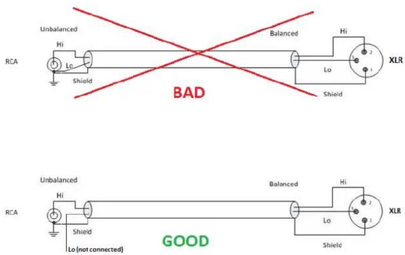
Furthermore, as Unbalanced Inputs are traditionally more sensitive than Balanced Inputs, the -6dB Analog level achieved by using only one of the Hapi symmetrical outputs, will offer better signal level adaptation with less risks of overdriving the Unbalanced Inputs connected to the Hapi.
IOM-H-DA8/DA8P block diagram.
DA8 / DA8P
![graph LR A["Digital input"] --> B["Digital Output Attenuation [0..-60dB"]] B --> C["Roll Off Filter"] C --> D["D/A converter"] D --> E["Analog Output Level Selection +18dB/+24dB"] E --> F["Mute Switch"] F --> G["Analog Output"]](/content/2026/05/903531/images/54adb3f9e2079d4a649064b3af72749f91a48ed30f5d94119f559fd1d65980af.jpg)
IOM-HORUS-DA8/DA8P (< run 11) - Legacy product
The DA8 (up to 192kHz) and the DA8P (up to DSD) have been shown in testing to be consistently the quietest multichannel D/A conversion modules available anywhere.

IOM-HORUS-DA8/DA8P Key Features
- Auto-mute circuitry for "no-pop" power cycling
• Digitally controlled trims for line up procedures
• Dynamic range of 127dB (typ.) - Easy to set dip switches for international operating levels
IOM-HORUS-DA8/DA8P Specifications
Max Line Output @ 0 dBFS (jumpers on +24 dBu) +24 dBu +0/-0.5 dB
Frequency response +0/-0.3dB @ fs = 48000 Hz 0 Hz - 20 kHz
Frequency response +0/-0.3dB @ fs = 2.8224 MHz (DSD) NA / 0 Hz - 20 kHz
Frequency response +0/-3.0dB @ fs = 2.8224 MHz (DSD) NA / 0 Hz - 50 kHz
Line Output Impedance (Differential) 100 Ω
Dynamic Range (A-weighted, typ) 126 dB
THD+N D/A (1 kHz) @ 0 dBFS (IOM-HORUS-DA8) < -113dB (0.00022 %)
THD+N D/A (1 kHz) @ 0 dBFS (IOM-HORUS-DA8P) < -115dB (0.00018 %)
Interchannel Crosstalk @ 1kHz, typ. -135 dB
Connector Pinout DB-25 / AES59 (Tascam Ana.)
Line Output Level calibration
The DA8 and DA8P modules feature both hardware level settings and a software fine adjustment to align the Analog Output levels to whatever local/organization operational levels are mandated.
On DA8/DA8P cards from run 7 upwards, the hardware level setting is done via software through the option "max output level" in each DA's setting page, allowing either +24 dBu or 18 dBu max level.
On DA8/DA8P cards prior to run 7 the hardware level setting is in the form of 4 DIP switches per output channel
The Hardware settings will usually be set only once, at product installation, and only if the desired Operating Line Level differs from the default ex-factory settings of +18 dBu for 0 dBFS.
Procedure for Hardware alignment (for DA8 prior to run 7):
- Shut down your Horus and make sure that the Horus back panel Power is also switched OFF.
- Unscrew all DA8 modules that need adjustment.
- Pull gently out (5-7 cm is enough) to access the DIP Switches. There is one block of 4 dip switches per channel. Channel 1 is labeled S1, channel 8 is labeled S8.

- Set the DIP Switches as per the table legend printed on the DA8 module card (run 6 and below)
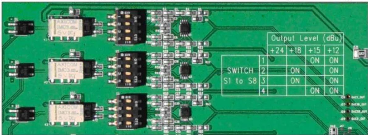
| Output Level (dBu) | |||||
| +24 | +18 | +15 | +12 | ||
| Switch S1 to S8 | 1 | ON | ON | ||
| 2 | ON | ON | |||
| 3 | ON | ON | |||
| 4 | ON | ON | |||
Output Level calibration Example:
Assuming your operating Level is 21 dBu for 0 dBFS (typical of French Radio Broadcasters), you should set the DIP Switches all OFF (DIP Switch positioned to the left, with respect to the picture below) to set maximum Output Level to +24 dBu (since there is no 21 dBu hardware setting)

Once this is set and the DA modules are screwed back in place. Power up the Horus and go to the Horus Setup Page>Module, select each D/A module for software calibration.
In this example case set the software attenuation to -3 dB (see image below), so the overall result ends up at 21 dBu for a Full Scale signal

The Hapi software Output Attenuation range is from -12dB to 0dB
How to connect the symmetrical line out to an unbalanced input
Never attempt to short pin 3 (or pin 2) to Ground on Horus DA's output, since the Horus Line Out driving circuitry is symmetrical but not floating.

Furthermore, as Unbalanced Inputs are traditionally more sensitive than Balanced Inputs, the -6dB Analog level achieved by using only one of the Horus symmetrical outputs, will offer better signal level adaptation with less risks of overdriving the Unbalanced Inputs connected to the Horus.
IOM-HORUS-DA8/DA8P block diagram
![graph LR A["Digital Input"] --> B["Digital Output Attenuation [0...-60dB"]] B --> C["Roll Off Filter"] C --> D["D/A converter"] D --> E["Analog Output Level Selection +12dB/+15dB/+18dB/+24dB"] E --> F["Mute Relay"] F --> G["Analog Output"] H["Digital Input"] --> I["Digital Output Attenuation [0...-6…](/content/2026/05/903531/images/c2acd1d2bdbe29519d477764ba0729c6fa519e45c1a9a5749f1875011ef4043f.jpg)
IOM-H-ADA8S/ADA8P
These remotely controlled Mic/Line Input and Output cards are 3rd generation Dual Gain topology designs, inspired from the Anubis outstanding Preamps, that show zero tolerance to any compromise on the audio quality.
Available in models that work up to 192kHz (ADA8S) and DXD/DSD256 (ADA8P)
Using those combined 8 channel Mic/Line In and Line Out cards allow the Hapi to be configured with up to 16 channels of Analog In/Out.

IOM-H-ADA8S/ADA8P Key Features
- 8 x exceptionally transparent, Swiss designed pre-amplifiers
- Remote/Local switch to Line Level on a per channel basis
• Completely accessible remotely for all parameter changes - Phantom Power/Polarity Invert/Low Cut/Impedance switchable per channel
• Dynamic range of 139dB (A-weighted, typ) on the Line inputs
• Auto-mute circuitry for "no-pop" power cycling
• Digitally controlled output trims for line up procedures
• Dynamic range of 124dB (A-weighted, typ.) on the Line outputs
IOM-H-ADA8S/ADA8P Specifications
IOM-H-ADA8S/ADA8P Mic-Pre + ADC Section
Mic Pre Max Input (Mic+Pad / Mic / Boost) +24 dBu / +12 dBu / +0 dBu Input Impedance (Differential, Software Switchable Per Channel) 3 kΩ / 10.4 kΩ
Input Impedance (ZIo; ZHi) 3 kΩ / 10.4 kΩ
Frequency response +0/-0.3dB @ fs = 48 kHz 9 Hz - 22 kHz
Frequency response +0/-3dB @ fs = 96 kHz 9 Hz - 46 kHz
Frequency response +0/-3dB @ fs = 192 kHz 11 Hz - 94 kHz
Dynamic Range Mic (A-weighted, typ.), ref +12 dBu 137 dB
Dynamic Range Mic Boost (A-weighted, typ.), ref 0 dBu 128 dB
Gain Range (software controlled) 0 dB to +66 dB
THD+N Pre + A/D (20 Hz - 20 kHz) @ -2 dBFS < -111 dB (0.00028 %)
Interchannel Crosstalk @ 1kHz < -130 dB
EIN @ >40 dB Gain (150Ω Source Impedance, A-weighted) < -127 dB
Common Mode Rejection Rate (20 Hz - 20 kHz) > 75 dB
Phantom Power (Software Switchable Per Channel) +48V
Polarity Invert (Software Switchable Per Channel) YES
Low Cut filter (Software Switchable Per Channel) -12 dB/octave, 80 Hz
IOM-H-ADA8S/ADA8P Line input Section
Max Line Input for 0 dBFS +24 dBu
Input Impedance (Differential) 10.4 kΩ
Dynamic Range (A-weighted, typ.), ref +24 dBu 139 dB
THD+N Line+A/D (20 Hz - 20 kHz) @ -2 dBFS < -111 dB (0.00028 %)
Interchannel Crosstalk @ 1kHz < -135 dB
Sensitivity Range for 0 dBFS (software controlled) -42 dBu to +24 dBu
Gain Step 0.5 dB
Common Mode Rejection Rate (20 Hz - 20 kHz) > 70 dB
Connector Pinout DB-25 / AES59 (Tascam Ana.)
IOM-H-ADA8S/ADA8P Line Out Section
Max Output level software switchable for 0 dBFS +24 dBu / +18 dBu +0/-0.5 dB
Frequency response +0/-0.3dB @ fs = 48 kHz 0 Hz - 22 kHz
Frequency response +0/-3dB @ fs = 96 kHz 0 Hz - 46 kHz
Frequency response +0/-3dB @ fs = 192 kHz 0 Hz - 92 kHz
Output Impedance (Differential) < 80 Ω
Dynamic Range (A-weighted, typ.) 125 dB / 126 dB
THD+N (1 kHz) @ 0dBFS < -115 dB (0.00017 %)
Interchannel Crosstalk @ 1kHz < -139 dB
Connector Pinout DB-25 / AES59 (Tascam Ana.)
IOM-H-ADA8S/ADA8P Dual preamp block diagram
IOM-H-ADA8S/ADA8P Dual PreAmp input diagram
![graph LR A["48V"] --> B["ProAmp"] B --> C["Gain + 4dB"] B --> D["A/D"] C --> E["Ato -17dB"] D --> F["A/D"] E --> G["Attenuation 21dB"] F --> H["DC remover"] G --> I["Advanced selection logic"] H --> I I --> J["Low cut"] J --> K["Digital gain"] K --> L["Σ/Δ (DSD only)"] L --> M["Output"]](/content/2026/05/903531/images/349d0e962e96776b2cc7c83e09407d24dd7552cd608f5392ae59823d5c4a20fd.jpg)
IOM-H-ADA8S/ADA8P block diagram
Data flow in PCM on ADA8S/ADA8P cards
![graph TD A["Analog input"] --> B["48V phantom power On / Off"] B --> C["Zin selector 3kΩ / 10.4kΩ"] C --> D["Preamp analog gain Line / Mic+Pad / Mic / Mic Boost"] D --> E["A/D converter"] F["DC remover"] --> G["Digital gain + low cut filter"] G --> H["PCM output"] I["32 bits"] --> E J["FPGA"] --> F…](/content/2026/05/903531/images/01ded338d5b53515e032eb676368670b832c444aef39eb573416ee77093ebeed.jpg)
* The ADA8P run 5 do not have Low Cut option
Data flow in DSD on ADA8P cards
![graph TD A["Analog input"] --> B["48V phantom power On / Off"] B --> C["Zin selector 3kΩ / 10.4kΩ"] C --> D["Preamp analog gain Line / Mic+Pad / Mic / Mic Boost"] D --> E["A/D converter"] E --> F["DC Remover"] F --> G["Digital gain + low cut filter"] G --> H["Σ/Δ Modulator"] H --> I["DSD output"] I…](/content/2026/05/903531/images/537fd4539d86c1988f21d7699690d943c868305650b813a35f99c54aab65357b.jpg)
* The ADA8P run 5 do not have Low Cut option
ADA8S and ADA8P Roll Off Filters:
Sharp: Offers a flat frequency response with an attenuation of 3 dB at 0.484 x FS (23.2 kHz @48k), which has the tradeoff of 35 samples latency.
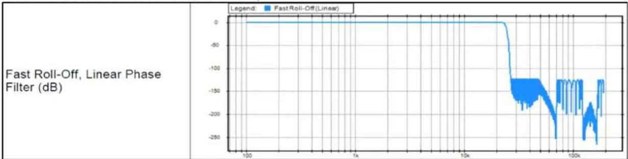
Slow (default): Offers the lowest latency of 9 samples, with the tradeoff of a gentle frequency response attenuation reaching -3dB at 0.45 x FS (21.6 kHz @48k)

Apodizing: Fast Roll-Off filter, Linear phase filter. Latency of 35 samples
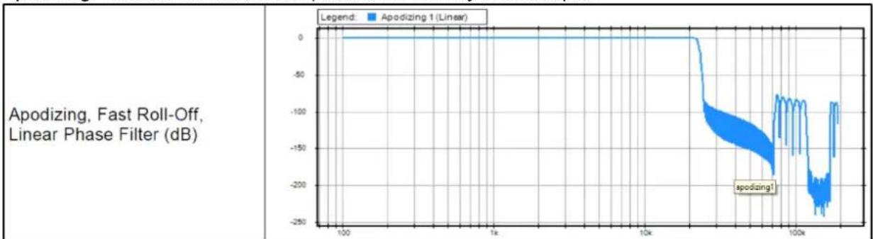
Brickwall: Ensures rejection of more than -100dB at Nyquist (0.50 x FS, 24 kHz @48k). Latency of 35 samples

IOM-H-ADA8 - Legacy Product
These remotely controlled Mic/Line Input and Output cards have broken a new barrier in terms of compactness as well as ultra-low power consumption without compromising on the audio quality. These cards work at sampling rates up to 192 kHz Using those combined 8 channel Mic/Line In and Line Out cards allow the Hapi to be configured with up to 16 channels of Analog In/Out.

IOM-H-ADA8 Key Features
- 8 x exceptionally transparent, Swiss designed pre-amplifiers
- Remote/Local switch to Line Level on a per channel basis
- Completely accessible remotely for all parameter changes
- Phantom Power/Polarity Invert/Low Cut/Impedance switchable per channel
• Dynamic range of 120dB (A-weighted, typ) on the Line inputs - Auto-mute circuitry for "no-pop" power cycling
• Digitally controlled output trims for line up procedures
• Dynamic range of 123dB (A-weighted, typ.) on the Line outputs
IOM-H-ADA8 Specifications
IOM-H-ADA8 Mic-Pre + ADC Section
| Mic Pre Max Input (Pad On / Pad Off) +24 dBu / +13 dBu | |
| Input Impedance (Differential, Software Switchable Per Channel) | 2 kΩ / 13.6 kΩ |
| Input Impedance with +48V ON (Diff., Soft. Switchable Per Channel) | 1.7 kΩ / 6.8 kΩ |
| Frequency response +0/-0.3dB @ fs = 48 kHz | 10 Hz - 22 kHz |
| Frequency response +0/-0.3dB @ fs = 96 kHz | 10 Hz - 44 kHz |
| Frequency response +0/-0.3dB @ fs = 192 kHz | 10 Hz - 85 kHz |
| Dynamic Range (A-weighted, typ.), ref +13 dBu | 119.5 dB |
| Gain Range (software controlled) 0 dB to +66 dB | |
| Gain Step/Precision 0.5 dB / ±0.2 dB | |
| THD+N Pre + A/D (20 Hz - 20 kHz) @ -2 dBFS | <-102 dB (0.0008 %) |
| Interchannel Crosstalk @ 1kHz | <-125 dB |
| EIN @ >40 dB Gain (150Ω Source Impedance, A-weighted) | <-128 dBu |
| Common Mode Rejection Rate (20 Hz - 20 kHz) | >60 dB (up to 0 dBFS) |
| Phantom Power (Software Switchable Per Channel) | +48V |
| Polarity Invert (Software Switchable Per Channel) | YES |
| Low Cut filter (Software Switchable Per Channel) | -12 dB/octave, 80 Hz |
IOM-H-ADA8 Line input Section
| Max Line Input for 0 dBFS | +24 dBu | |
| Input Impedance (Differential) | 13.6 kΩ | |
| Dynamic Range (A-weighted, typ.), ref +24 dBu | 120 dB | |
| THD+N Line+A/D (20 Hz - 20 kHz) @ -2 dBFS | <-102 dB (0.0008%) | |
| Interchannel Crosstalk @ 1kHz | <-125 dB | |
| Sensitivity Range for 0 dBFS (software controlled) | -42 dBu to +24 dBu | |
| Gain Step/Precision | 0.5 dB / ±0.2 dB | |
| Common Mode Rejection Rate (20 Hz – 20 kHz) | >60 dB (up to 0 dBFS) | |
| Connector Pinout | DB-25 / AES59 (Tascam Ana.) |
IOM-H-ADA8 Mic-Pre Analog Section
Frequency response +0/-0.5 dB, Line 5 Hz - 75 kHz
Frequency response +0/-2.0 dB, Line 2.5 Hz - 150 kHz
Frequency response +0/-0.5 dB, Mic 10 Hz - 100 kHz
Frequency response +0/-2.0 dB, Mic 5 Hz - 200 kHz
THD+N (1 kHz), Line/Mic at G=0dB <-115 dB (0.00018 %)
THD+N (20 Hz-20 kHz), Line/Mic at G=0dB <-112 dB (0.00025 %)
Interchannel Crosstalk @ 1kHz, typ. -135dB
5° low-end in-channel ∅ deviation pt: Line 13 Hz
5° low-end in-channel ∅ deviation pt: Mic 35 Hz
Interchannel phase 10 Hz - 100 kHz < ±0.1°
IOM-H-ADA8 Line Out Section
Max Output level software switchable for 0 dBFS +24 dBu / +18 dBu +0/-0.5 dB
Frequency response +0/-0.3dB @ fs = 48 kHz 0 Hz - 22 kHz
Frequency response +0/-3dB @ fs = 96 kHz 0 Hz - 44 kHz
Frequency response +0/-3dB @ fs = 192 kHz 0 Hz - 88 kHz
Output Impedance (Differential) < 100 Ω
Dynamic Range (A-weighted, typ.) 123 dB
THD+N (1 kHz) @ 0dBFS < -108 dB (0.0004 %)
Interchannel Crosstalk @ 1kHz < -135 dB
Connector Pinout DB-25 / AES59 (Tascam Ana.)
IOM-H-ADA8 block diagram
![graph LR A["Analog Input"] --> B["48V phantom power\nOn / Off"] B --> C["Zin selector\n2kΩ / 6.8kΩ / 13kΩ"] C --> D["Preamp analog gain\n0 to +40dB"] D --> E["Mic / Line pad\n-15dB"] E --> F["A/D converter"] F --> G["Digital gain"] style A fill:#f9f,stroke:#333 style G fill:#bbf,stroke:#333](/content/2026/05/903531/images/6ad55d670b52a2115de875a235085d8964f48d62abeb75b7241fe835694ed391.jpg)
![graph LR A["Digital Input"] --> B["Digital Output Attenuation [0 ... -60dB"]] B --> C["Roll Off Filter"] C --> D["D/A converter"] D --> E["Analog Output Level Selection +18dB/+24dB"] E --> F["Mute Switch"] F --> G["Analog Output"]](/content/2026/05/903531/images/e3541e44f943ca2124242e70e454d2c08d34b05064c2459704041f34465ec9d7.jpg)
IOM-H-PT64
This module allows you to connect your Hapi directly to a Pro Tools HD or Pro Tools HDX system through its two Digilink Mini connectors. You can plug up to two modules in a device, meaning you can record up to 128 Channels at a time.

IOM-H-PT64 Key Features
- Up to 64 Channels @48kHz per module (32 ch. @ 96kHz, 16 ch. @192kHz)
- Up to two IOM-H-PT64 modules in one Horus/Hapi
• Automatic Delay Compensation - Three hardware emulation modes (Digidesign 192I/O, HDIO and HDMADI)
- Two Digilink mini connectors
Ports usage
There are two connectors on the IOM-H-PT64 module called Port 1 and Port 2.
Working at 44.1/48kHz, both Ports are enabled. Channels I/O 1-32 are carried through Port 1 and channels I/O 33-64 through Port 2. If only 32 channels are needed, it is possible to use only Port 1 or only one of Port 1 or Port 2 in HD I/O or 192 I/O modes only.
With a Sample Rate of 88.2/96kHz, only Port 1 is enabled. All 32 I/O channels will be carried through this Port.
If the Sample Rate is set to 176.4/192kHz, then all 16 I/O channels will be carried through Port 1 as well.
Port 1 of your IOM-H-PT64 should always be connected to Port 1 on the AVID interface and Port 2 should always be connected to Port 2 even if just one Port is used.
Note: Cables of same length must be used when both ports are connected.
Note: When using 2 IOM-H-PT64 cards in a single device in order to benefit from 64 channels at 88k2/96k, you can connect Port 1 of the first card to HDX/HD Native Port1 and Port 1 of the second card to HDX/HD Native Port2.
Synchronization and Word Clock
When properly configured, Hapi is able to automatically change its internal clock to match a Pro Tools project's Sample Rate. The proper IOM-H-PT64 module must be selected in the I/O & Sync menu (PT 1 or PT 2 if module is in Slot 1 or 2). The Auto-follow option must be enabled in Setup -> Format menu, and Hapi will change its Internal Sample Rate automatically.

In Pro Tools, the Clock source should be set to Internal for the device emulated by the IOM-H-PT64 module (HD MADI in the following example).

Sampling Rate mismatch protection
Audio from Pro Tools to Horus and from Horus to Pro Tools is muted when the Sampling Rate asked by PT is not met by Horus to avoid recording when Sampling Rates mismatch.
Enable the Auto-follow SR option and Synchronize on PT module to avoid any SR mismatch.
Setups with multiple devices
If your setup is made of several Pro Tools Hardware interfaces that need to be synchronized, our recommendation is to select Internal Clock Source of your IOM-H-PT64 module as the Master Clock. The other devices present in the setup can be synchronized several different ways.
If two Hapi interfaces are used in a setup, they can be synchronized through the Word Clock connectors. To send the actual Sample Rate, the Follow SR option in Setup -> Format must be enabled.
![graph TD A["Pro Tools HD/HDX"] -->|HD Card 1| B["IOM-H-PT64"] C["Clock Source : Hapi 1 Internal"] -->|HD Card 2| B B --> D["Sync source : IOM-H-PT64 WCK Out"] D --> E["WCK In"] E --> F["IOM-H-PT64"] F --> G["Sync Source: WCK"] G --> E style A fill:#f9f,stroke:#333 style C fill:#f9f,stroke:#333 style…](/content/2026/05/903531/images/07b26686026a0a3129ebedd438569002ef6fe19c62b62466793b2c31e25e62bf.jpg)
The next setup is using Hapi as the Master clock for all devices. In this case, the Clock Source must be set to the other device's Word Clock. The Follow SR option in Setup -> Format must be enabled.
![graph TD A["Pro Tools HD/HDX\nClock Source :\nOther device's WClk In"] -->|HD Card 1| B["IOM-H-PT64"] A -->|HD Card 2| C["Additional HDLink capable interfaces"] B <--> D["Sync Source:\nIOM-H-PT64\nWCK Out"] B <--> E["Hapi 1"]](/content/2026/05/903531/images/9cc9f783ef93f4c7e516a42f873c2a9979b4270c6476fb95202fa7ba6efbbae5.jpg)
In the following setup, an external Master Clock is used for all devices. In this case, the external Master Clock controls the Hapi Sample Rate. Hence, the external Master Clock must be set accordingly to the Pro Tools project Sample Rate.
![graph TD A["Pro Tools HD/HDX\nClock Source :\nExternal Master Clock"] -->|HD Card 1| B["IOM-H-PT64"] B <--> C["Sync Source: WCK"] C -->|WCK In| B B -->|WCK Out| D["External Master Clock"] D -->|Additional HDLink capable interfaces| B B -->|HD Card 2| A](/content/2026/05/903531/images/ecfa7af86dfec544287d9545cb687b9ff820621d66999ee2297abd130f69862f.jpg)
IOM-H-PT64 block diagram
![graph LR A["From Pro Tools"] --> B["Block"] B --> C["Output DelayDecoder"] C --> D["To Hapi"] E["To Pro Tools"] --> F["Block"] F --> G["Input DelayEncoder"] G --> H["From Hapi"]](/content/2026/05/903531/images/725f948f0254f3bf536872746a46048bc51fd649f8ae7d7bbfc8eb85d80900a6.jpg)
Delay compensation
Input and Output delay are strongly dependent on the Hardware. This implies that if one records a single source with two different devices at the same time, one will get two slightly out-of-phase tracks. This is explained by the fact that every device has its own circuitry and different components.
To minimize this issue, Pro Tools implemented an Auto Delay Compensation feature which will automatically shift the recording depending on the Hardware used.
The IOM-H-PT64 module was made to emulate three different Digidesign interfaces and match every interface's actual input/output latency (within a margin of maximum 3 samples). This chart shows what latency to expect for different setups. Analog/Digital modules latencies are already included in these measures.
| Emulation Mode | Routing | 44k1/48k | 88k2/96k | 176k4/192k | |
| None | Input | - | 2* smpl. | 2* smpl. | 2* smpl. |
| Output | - | 2* smpl. | 2* smpl. | 2* smpl. | |
| 192IO | Input | From AD8D | 65 smpl. | 65 smpl. | 65 smpl. |
| Output | To DA8 | 24 smpl. | 14 smpl. | 15 smpl. | |
| HDIO | Input | From AD8D | 16 smpl. | 12 smpl. | 11 smpl. |
| Output | To DA8 | 56 smpl. | 21 smpl. | 21 smpl. | |
| HD MADI | Input | From MADI | 6 smpl. | 6 smpl. | 7 smpl. |
| Output | To MADI | 5 smpl. | 5 smpl. | 7 smpl. |
* Added to the other modules used
For the delay compensation to be working, it must be enabled in the ProTools software (Options -> Delay Compensation).
Emulation Mode
Configures which Digidesign interface the IOM-H-PT64 module will emulate in Pro Tools. This option does not affect the Hapi routing or preamps, it will just set the Input/Output Delays as seen above. When set to None, Pro Tools will see the module as an HD MADI, but Hapi will use the minimum latency. Therefore, Delay Compensation will not be accurate on Pro Tools in this mode.
Error AAE -6116
When Hapi is configured to follow the Sample Rate asked by Pro Tools, an AAE -6116 error might happen when opening a project with a new Sample Rate. If it happens, click OK to close the error information. Then, when trying to play the file, the error might show again. After clicking OK, the error should not appear again.
If this issue is too frequent, a way to avoid it is to disable the Auto-Follow option in Setup -> Formats and change the Sample Rate on Hapi by hand. This should reduce the probability of getting such an error.
IOM-HAPI-MADM/MADS
The MADI optional Module card (MADM - Multimode / MADS – Single mode) provides a channel count of 64 inputs and 64 outputs @1FS

IOM-HAPI-MADM/MADS Features
- MADI Optical and Coaxial inputs and outputs
- 64 discrete channels of digital input and output (extended mode) at 1FS
- Up to 384 kHz sampling rate
- 24-bit resolution
• Fully compliant MADI (AES 10-1991) - 2 BNC and 1 SC connectors (Multimode or single mode)
Single mode fibers have a lower power loss characteristic than multimode which means that it supports longer runs but single mode fibers are more expensive. The multimode version (IOM-HAPI-MADM) is the most widely used optical MADI connection, but for fiber lengths of more than 600m. Merging Technologies recommends to use the single mode version (IOM-HAPI-MADS).
HAPI - Cables
Connecting the analog audio Input cables to the AD8/AD8P/AKD8D/AKD8DP/ADA8S/ADA8P modules
The AD/AD8(P) / AKD/AKD8(P) / ADA8(P) modules connect the Mic/Line Inputs using DB25 D-SUB connections.
Please ensure that the cables you have chosen to use, or have had made, conform to this specification before you attempt to connect them.

Specifications
Part: CON-D25-XLRF
- Cable Color: black
- Numbered XLR fan-out
- Cable ∅: 12 mm
- Cable Length: 1,5 m
- Cable Weight: 500 gr
| In 1 | In 2 | In 3 | In 4 | In 5 | In 6 | In 7 | In 8 |
| Pin 24= (+)Pin 12 = (-) | Pin 10= (+)Pin 23 = (-) | Pin 21= (+)Pin 9 = (-) | Pin 7= (+)Pin 20 = (-) | Pin 18= (+)Pin 6 = (-) | Pin 4= (+)Pin 17 = (-) | Pin 15= (+)Pin 3 = (-) | Pin 1= (+)Pin 14 = (-) |
| GND is connected to Pins: 2, 5, 8, 11, 16, 19, 22, 25. Pin 13 is not connected | |||||||
To connect the DSUB connection to the module, align the Male cable connector with the female DSUB port on the module. Then, with slight pressure, guide the connector into place. If your DSUB connector has retention screws on either side, then fasten them finger-tight once the connector has been pushed into place.
Note: The pinout of the DB-25 is as per AES59 (Tascam Analog).
* THESE CONNECTIONS ARE NOT MEANT TO SUPPORT ANY SIGNIFICANT WEIGHT.* Ensure that there is no strain from the connected cable as any significant pressure on the module's DSUB connector could damage the Hapi unit.
Connecting the analogue outputs cables to the DA8/DA8P modules
The IOC-DA8(P) modules connect the line outputs using DB25 D-SUB connections.
Please ensure that the cables you have chosen to use, or have had made, conform to this specification before you attempt to connect them.

| Specifications |
| Part: CON-D25-XLRMCable Color: blackNumbered XLR fan-outCable ∅: 12 mmCable Length: 1,5 mCable Weight: 500 gr |
| Out 1 | Out 2 | Out 3 | Out 4 | Out 5 | Out 6 | Out 7 | Out 8 |
| Pin 24= (+)Pin 12 - (-) | Pin 10= (+)Pin 23 - (-) | Pin 21= (+)Pin 9 - (-) | Pin 7= (+)Pin 20 - (-) | Pin 18= (+)Pin 6 - (-) | Pin 4= (+)Pin 17 - (-) | Pin 15= (+)Pin 3 - (-) | Pin 1= (+)Pin 14 - (-) |
| GND is connected to Pins: 2, 5, 8, 11, 16, 19, 22, 25. Pin 13 is not connected | |||||||
To connect the DSUB connection to the IOC-DA8(P), align the Male cable connector with the female DSUB port on the module. Then, with slight pressure, guide the connector into place. If your DSUB connector has mounting screws on either side, then fasten them finger-tight once the connector has been pushed into place.
Note: The pinout of the DB-25 is as per AES59 (Tascam Analog).
* THESE CONNECTIONS ARE NOT MEANT TO SUPPORT ANY SIGNIFICANT WEIGHT.* Ensure that there is no strain from the connected cable as any significant pressure on the module's DSUB connector could damage the Hapi unit.
Connecting the AES-EBU cable
The AES ports connect the AES-EBU I/O using DB25 D-SUB connections.
Please ensure that the cables you have chosen to use, or have had made, conform to this specification before you attempt to connect them.

Specifications
- Part: CON-D25-XLRD
- 192 kHz ready
- Cable Color: black
• Impedance: 110 Ohm
• Numbered XLR fan-out - Cable ∅: 12 mm
• Cable Length: 1,5 m - Cable Weight: 500 gr
| AES In 1 (1/2) | AES In 2 (3/4) | AES In 3 (5/6) | AES In 4 (7/8) | AES Out (1/2) | AES Out (3/4) | AES Out (5/6) | AES Out (7/8) |
| Pin 24= (+)Pin 12 = (-) | Pin 10= (+)Pin 23 = (-) | Pin 21= (+)Pin 9 = (-) | Pin 7= (+)Pin 20 = (-) | Pin 18= (+)Pin 6 = (-) | Pin 4= (+)Pin 17 = (-) | Pin 15= (+)Pin 3 = (-) | Pin 1 = (+)Pin 14 = (-) |
| GND is connected to Pins: 2, 5, 8, 11, 16, 19, 22, 25. Pin 13 is not connected | |||||||
To connect the DSUB connection to the AES port, align the Male connector with the female DSUB port on the module. Then, with slight pressure, guide the connector into place. If your DSUB connector has mounting screws on either side, then fasten them finger-tightn once the cable has been pushed into place.
Note #1: The pinout of the DB-25 is as per AES59 (Tascam Digital).
Note #2: Users that have Mykerinos AES or Dual cables cannot use those with their Horus or Hapi as the pin out is not compatible.
Note #3: DB25 TDIF cables are not compatible with Horus/Hapi AES
* THESE CONNECTIONS ARE NOT MEANT TO SUPPORT ANY SIGNIFICANT WEIGHT.* Ensure that there is no strain from the connected cable as any significant pressure to the module's DSUB connector could damage the Hapi unit.
Connecting the MADI cable
The MADI port (optional MADI Module) can be connected using either Optical or coaxial cabling.

When using Optical cabling, first ensure that you have a clean work area, as dust and debris can affect the connection if any obstruction is present. Remove the cap on both the cable and the port and slowly / firmly push the cable into the receiving port on the Hapi unit until it clicks into place. The MADI optical connector is available in Multimode or Single mode versions. The Hapi is delivered with Multimode connectors unless specified at ordering.
For Multimode MADI i/o Merging recommends the use of the OM1 or OM2 Category, with specifications of 62.5/125 um or 50/125 um. OM3 and OM4 specifications are also supported since those are improved versions of OM2. The wavelength should be 1300 nm.

When Using a Coaxial connector. Slowly bring the Male cable up to the female port, ensuring that the pin in the centre of the male cable lines up with the receptacle in the female port. Push the connector firmly into place and twist the sleeve clockwise until it clicks into its locked position. Maximum recommended cable length is 100 meters
Connecting the Wordclock input/output

The Wordclock connections on the rear of the Hapi unit are coaxial BNC's. To connect a Wordclock source from an external device slowly bring the Male cable up to the female port, ensuring that the pin in the centre of the male cable lines up with the receptacle in the female port. Push the connector firmly into place and twist the sleeve clockwise until it clicks into its locked position.
Connecting the Sync Cable
The Sync Cable (optional with each Hapi unit) is a DB15 cable that connects to the "SYNC" port on the rear of the Hapi unit. The SYNC cable provides connectivity for LTC and Video Reference Input and Output for the Hapi unit. To attach this cable to the Hapi unit, align the male connector with the female DSUB port on the module. Then, with slight pressure, guide the connector into place. Once the cable has been pushed into place, fasten the mounting screws on either side finger-tight.
Note: The Hapi provides Video Reference I/O Synchronization, but is not a Video reference Generator.

Sync breakout cable pin-out

Connecting the RAVENNA Ethernet cables

The RAVENNA ports (Primary and Secondary) are RJ45 female receptacles. Simply line up the RJ45 cable with the slot on the rear of the Hapi unit and slide it into place until it clicks into its locked position.
(Category 5E or 6)
Note: Use the primary (PRI) port. Secondary port behavior depends on the ST2022-7 mode, set in the Hapi Advanced pages (default mode: network switch mode). See Network menu – Network operations modes for details.
HAPI MKII Key Features
Networking
The Merging Hapi MKII fully supports (2) RJ45 connectors, that can be configured in two different modes, from the RAVENNA Advanced Pages.
1) ST2022-7 mode for network redundancy (Seamless Protection Switching)
2) Network Switch mode, allowing the daisy-chaining of one additional network device without the need for an external network switch.
Modular analog interfacing
Hapi allows the user to choose between Analog inputs and Analog outputs and MADI I/O required for each unit. Hapi provides a total of 2 universal I/O slots which can accept a combination of Mic/Line modules and or Line output cards and or a MADI module. Configure Hapi with any combination. For instance, in a studio environment, 8 A/D (1X IOC-AD8/P) and 8 D/A (IOC-AD8/P) will allow for 8 inputs from the live room and 8 outputs to feed studio monitoring and foldback to the artist.
Modular Device connectivity
Any of the modules listed below (A/D, D/A, MADI, AES, ADAT/SPDIF, RAVENNA) can be interconnected in any way the user chooses. Simple and easy routing pages enable the user to source signal from any module, and send it to any other combination of modules. An A/D Module could feed 8 Channels of AES Outputs. At the same time, it could feed to 8 MADI channels, or even the RAVENNA stream as well. This is the function that allows the user operate with the Hapi in either a standalone (Analog to MADI/AES AD/DA) or in RAVENNA Mode, which connects the audio to a RAVENNA network (described below).
With such a wealth of different outputs, it made sense to apply a “route to” instead of a “route from” philosophy in the way Hapi presents its routing pages. After an initial learning period, you will understand that this is a much more efficient way to present so many routing options in an easy to unfold process. So always ask yourself first which output is being considered and then decide what input signal will feed that output and you will be offered all logical and valid choices at every step. It also made sense to limit the granularity of routing options to blocks of 8 channels, as a good compromise between flexibility and complexity.
AD8 / AD8P Remote controlled Mic/Line A/D module
The AD8 (works up to 192 kHz) and the AD8P (works up to DXD/DSD256) are remote controllable, extremely high-quality Microphone pre-amplifiers with a switch on each channel to route the signal through dedicated line level circuitry instead. The remote control is achieved over Ethernet, via the RAVENNA Port at the back of the chassis. With all standard analogue controls also available via remote (Phantom power on a “per channel” basis, polarity invert, HPF) and a Gain stage reaching from -10dB all the way up to +60dB, these modules are not only easy to use, but completely transparent to listen to as well.
DA8 / DA8P Safety Conscious Analogue Line output Modules
The DA8 (works at sample rates up to 192 kHz) and DA8P (works at sample rates up to DSD) are specifically designed with the user's speakers in mind. Incorporating analogue mute circuitry, the DA8/P modules provide protection against spurious transients that may occur during Sample rate changes and power cycling "clicks" and "pops" which can damage not only speakers, but also the listener's ears. When you add to that a noise floor of less than -125dB, these are the ultimate analog outputs for any monitoring system.
ADA8 Remote controlled Mic/Line A/D module with transparent Analog output
The ADA8 v1, ADA8S v2 (work at sample rates up to 192 kHz) and the ADA8P v2 (works at sample rates up to DSD) are combining high quality Microphone pre-amplifiers and analog output module.
HD Link with Pro Tools HD
The PT Module allows the Horus to communicate with a Pro Tools HD card. With two modules in one interface, up to 128 channels can be recorded simultaneously.
DC power supply options
Your Hapi interface can be fitted with a DC power supply input, this can be used to battery power the device or as a secondary power input. The maximum power requirement is 30W thus the supplied current must be of 2.5A if powered with 12V.
The DC power supply option can be used in two way
1- Battery power: The Hapi can be operated from battery, or any external DC adapter provided the voltage is between 10V and 14V.
2- Redundant power supply: The Hapi can be operated in a redundant way when using the standard AC power inlet and an external 12V DC adapter connected to the DC input of Hapi, in this configuration either power input can fail or be removed without creating any disruption in the device's operation.
MADI (Module)
A MADI module is available and can be fitted in one of the Hapi slots. It provides users with up to 64 channels of MADI I/O for use with the system. The signal sent to the MADI Outputs are configurable in blocks of 8 channels and can be sourced from any other module in the Hapi.
Note: Only one MADI module can be fitted per Hapi, please refer to the MADI module section above.
AES-EBU
1 x D-SUB25 connectors providing 8 channels (4 AES pairs) of AES-EBU I/O are Included as standard. The AES-EBU signal is transmitted as single wire at all supported sampling rates.
ADAT/SPDIF
8 ADAT I/O or 2 SPDIF I/O (on TOSLINK) are Included as standard. This module is supported up to 4FS (192 kHz)>.
Note: It is recommended to use 3 Meters and less cable length for proper transparency
PT64
64 Channels of Pro Tools HD™ support on Digilink mini connector, from 44.1 to 192 kHz sample rates
Signal routing paradigm
Hapi is quite possibly the most flexible audio interface ever designed. Users can literally route any input signal to any output module. Better yet, it can route any input signal to any combination of output modules. Routable in blocks of 8 channels, a user can send 8 Mic Inputs to 8 AES outputs. At the same time these 8 mic inputs can also be sent via the MADI outputs and included in the RAVENNA stream.
RAVENNA IP Audio
Using RAVENNA IP audio, Hapi can connect to a standard network, using off the shelf switches and other IT technology to become a node on a LAN. From that point, any other RAVENNA node can receive information from and deliver information to, any combination of RAVENNA devices on the network. It is a revolution in Audio technology and will soon mean the end to costly audio routers and matrices and allow any facility an immense amount of flexibility. From Broadcast and TV/Film post-production, to music, live events, theatres, cruise ships and many more applications, the RAVENNA Enabled Hapi interface will reinvent how systems come together.
The Hapi MKII with its dual network interface provides supports for two different modes of operations.
■ ST2022-7 Seamless Protection Switching. For full network redundancy.
■ Network Switch mode, allowing the daisy changing of one extra network interface connected directly to one of the Hapi MKII RJ45 port.
Notice: We do not support multiple daisy chained devices from the Hapi second ethernet port in switch port. A properly configured Network switch is recommended in order to daisy chain more than one additional hardware audio interface.
Hapi MKII is NMOS compliant
■ NMOS IS-04 (Discovery & Registration)
■ NMOS IS-05 (Device Connection Management)
Synchronization
Audio is not the only information that can pass down the RAVENNA connection. Hapi is also able to send sync (LTC) down the same wire to and from the Hapi unit. For more details refer to the RAVENNA network guide available on www.merging.com
Key Specifications
Please see the sections below for the measurement performed on the circuitry inside the Hapi unit.
HAPI MKII - Modules Capabilities
| Sampling Rates | 44.1/48kHz | 88.2/96kHz | 176.4/192kHz | DXD/384kHz | DSD64 | DSD128 | DSD256 | |
| MODULES | AD8 - AD8D - AKD8D - AKDG8D standard | √ | √ | √ | ||||
| AD8P - AD8DP - AKD8DP - AKDG8DP premium | √ | √ | √ | √ | √ | √ | √ | |
| DA8 standard | √ | √ | √ | |||||
| DA8P premium | √ | √ | √ | √ | √ | √ | √ | |
| ADA8 | √ | √ | √ | |||||
| ADA8S standard | √ | √ | √ | |||||
| ADA8P premium | √ | √ | √ | √ | √ | √ | √ | |
| PT64 | √ (64 I/O) | √ (32 I/O) | √ (16 I/O) | |||||
| Headphone | √ | √ | √ | √ | √ | √ | √ | |
| MADI | √ (64 I/O) | √ (32 I/O) | √ (16 I/O) | √ (8 I/O) | ||||
| AES | √ | √ | √ | |||||
| ADAT | √ (8 I/O) | √ (4 I/O) | √ (2 I/O) | |||||
| SPDIF | √ (2 I/O) | √ (2 I/O) | √ (2 I/O) | |||||
HAPI MKII - Modules Latencies
| Sampling Rates | 44.1 / 48kHz | 88.2 / 96kHz | 176.4 / 192kHz | DXD / 384kHz | |
| MODULES | AD standard premium | 15 smpl. | 10 smpl. | 8 smpl. | 8 smpl. |
| AKD standard premium | 8 smpl. | 8 smpl. | 9 smpl. | 10 smpl. | |
| AKDG standard premium | 9 smpl. | 9 smpl. | 9 smpl. | 9 smpl. | |
| DA standard premium | 12 smpl. * | 12 smpl. * | 12 smpl. * | 12 smpl. * | |
| ADA8 Input | 16 smpl. | 16 smpl. | 13 smpl. | N/A | |
| ADA8 Output | 9 smpl. ** | 9 smpl. ** | 9 smpl. ** | N/A | |
| ADA8S/P Input standard premium | 9 smpl. | 9 smpl. | 9 smpl. | 11 smpl. | |
| ADA8S/P Output standard premium | 9 smpl. ** | 9 smpl. ** | 9 smpl. ** | 9 smpl. ** | |
| PT64 | 2 smpl. | 2 smpl. | 2 smpl. | N/A | |
| Headphones | 15 smpl. | 8 smpl. | 8 smpl. | 8 smpl. | |
| MADI | 3 smpl. | 3 smpl. | 3 smpl. | 3 smpl. | |
| AES | 3 smpl. | 3 smpl. | 3 smpl. | N/A | |
* DA Filter setting
- Slow Roll Off Filter option = 12 Samples
- Sharp Roll Off Filter option = 39 Samples
(More details available under the DA Module chapter below)
** ADA Filter setting
- Slow Roll Off Filter option = 9 Samples
- Sharp Roll Off Filter option = 38 Samples
Note: Internal router of the Hapi MKII may add up to 1 sample of latency
Installing an additional Hapi I/O Module
Installing additional Hapi I/O Cards (AD8/AD8P/AD8D/AD8DP/ADA8 or DA8/DA8P)
Before you start
- Place the Hapi unit on a hard, dry surface or mount it onto a 19" rack and leave plenty of room for air convection.
- In order to meet the EMC requirements of directives 89/336/EEC and 93/68/EEC, and in order to obtain the high performance possible for the Hapi unit, you must use correctly shielded cables of good quality for all external connections when installing the Hapi unit. For the power connection, a normal unshielded power cable with a proper ground can be used.
- Make sure that your sound system is at a safe volume level.
Hardware Installation
This section will take you through installation of your Hapi unit. We will describe how to mount the I/O modules and the power, audio and digital cable connections that can be accessed on the rear panel.
*PLEASE ENSURE THAT YOUR HAPI UNIT IS SWITCHED OFF BEFORE ATTEMPTING TO CONNECT ANY CABLES TO THE UNIT.*
If you need to mount an I/O module at a later stage, the following procedure is used.
-
Place the shutdown Hapi unit on a dry steady horizontal surface. Remove all cables (including the power cable).
-
On the back of the Hapi unit there are 2 slots for mounting the Analog I/O cards or a MADI card.
-
To remove blind plates from I/O module slots, remove the 2 screws on either side of the plate. Use a Phillips (cruciform) screwdriver tool size 2
-
Only remove the number of blind plates necessary to fit the I/O module(s). If only one I/O slot is installed, remove only 1 blind plate. If 2 I/O slots are installed, remove 2 blind plates.
-
It is very important to insert the I/O card horizontally and carefully into the Hapi unit. There are 6 set of guides inside the Hapi unit to guide the I/O cards correctly into place. Do not use force in any way to insert the I/O card. This may damage the card. Slide card slowly as picture below shows.

-
When the cover plate of the I/O card covers the hole created by removing the blind plate, the 2 screws from the blind plate are mounted in the sides of the I/O card. Tighten the screws carefully and be careful not to damage the threads.
-
After inserting the I/O module, the Hapi unit might need to be initialized. If this is the case, please follow the instructions received with the I/O module.
Installing a Hapi MADI Module (MADM or MADS are optional)
Before you get started
- Place the Hapi unit on a hard and dry surface or mount it into a 19" rack and leave plenty of room for air convection.
- In order to meet the EMC requirements of directives 89/336/EEC and 93/68/EEC, and in order to obtain the high performance possible for the Hapi unit, you must use correctly shielded cables of good quality for all external connections when installing the Hapi unit. For the power connection, a normal unshielded power cable with a proper ground can be used.
- Make sure that your sound system is at a safe volume level
- Only one MADI module card can be fitted per Hapi
Hardware Installation
This section will take you through installation of your Hapi unit. We will describe how to mount the I/O modules and the power, audio and digital cable connections that can be accessed on the rear panel.
*PLEASE ENSURE THAT YOUR HAPI UNIT IS SWITCHED OFF BEFORE ATTEMPTING TO CONNECT ANY CABLES TO THE UNIT.*
Installing Hapi MADI I/O module procedure
The MADI module packaging includes the MADI module along with; two M3 screws, two M2 screws and a ribbon cable.
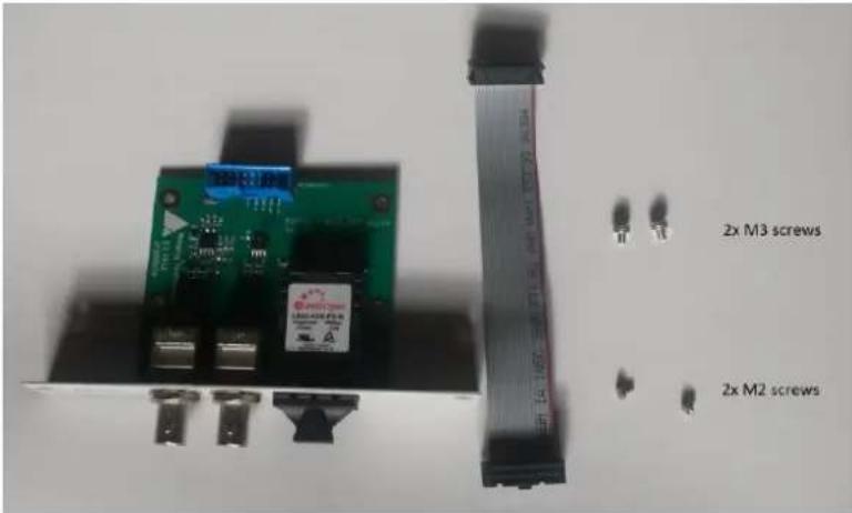
-
Place the Hapi unit on a dry steady horizontal surface. Remove all cables (including the power cable) and unscrew the Hapi top panel.
-
On the Back Panel first slot cover plate
Unscrewed 1 st module (Slot 1) cover plate

-
Open the Hapi top panel
-
Slide the MADI extension board carefully so that the back panel of the module touches the Hapi back panel.
-
Align the MADI Module over the 2 spacers and screw the MADI module using the 2x M3 screws.
-
Connect the ribbon cable from the MADI module to the J7 connector on the Main Hapi board. The connector is on the right on the Ethernet 2 and the closet to the MADI module.

-
Fix the module to the Hapi rear panel using the two M2 screws
-
Replace any modules that were removed earlier to provide access
-
Close the Hapi top panel cover and replace the fixing screws
-
Power the Hapi back on and the MADI module will be recognized
Assembling the Rack Mount ears
Hapi is delivered with two rack mount ears for easy installation into a 19" rack. The ears can be mounted either on the front or the rear of the device.
Installing the rack mount ears on the front panel
- Turn off and unplug your Hapi
- Unscrew the eight (8) M3x5 screws located on the side of the device (4 screws per side)
- Place the rack mount ears on the side of Hapi, as shown in the pictures below


- Fix the ears with the four (4) M3x8 screws delivered with the ears
Installing the rack mount ears on the rear panel
- Turn off and unplug your Hapi
- Place the rack mount ears on the side of Hapi, as shown in the pictures below


- Fix the ears with the four (4) M3x8 screws delivered with the ears
Hapi recommended placement in Rack
Due to confined space in a rack furniture, adequate spacing (and ordering) between multiple Hapi or Horus units will play a significant role on the units temperature. Although Merging has spent considerable time in optimizing the Hapi power consumption in every aspect possible, the units are still drawing an average of 30W. The dissipation of the related heat produced by this consumption is therefore highly dependent on the airflow and natural air convection around those units.
With highly loaded Horus units (more than 3 I/O Analog modules per unit) or Hapi units (2 I/O Analog modules per unit), Merging recommends a free space of 1U above each unit to ensure adequate cooling of the devices, if no other heating elements are present.
Installing the Merging NET-MSC-GBEX1
(PCIe Ethernet Controller Card for MassCore users only)
Detailed steps on how to install the NET-MSC-GBEX1 PCIe card in your PC.

- Power down your PC and switch it off at the wall. Remove the screws holding the top or side of the case on and carefully slide off the panel.

-
Wearing an anti-static wristband is desirable whenever working with sensitive electrical equipment. Keeping one hand on a metal part of the case will have the same effect, though you may need both hands when installing certain items of hardware.
-
Locate an empty PCIe slot and remove the metal backing plate by removing the screw holding it in place and carefully sliding it up and out. In some cases, there are no backing plates and you will need to remove a length of metal instead. Do this using a flat-blade screwdriver and/or pliers, taking care to avoid any sharp edges left behind.
-
Next, remove the NET-MSC-GBEX1 card from its envelope bag and line it up with the vacant PCIe slot as shown below.
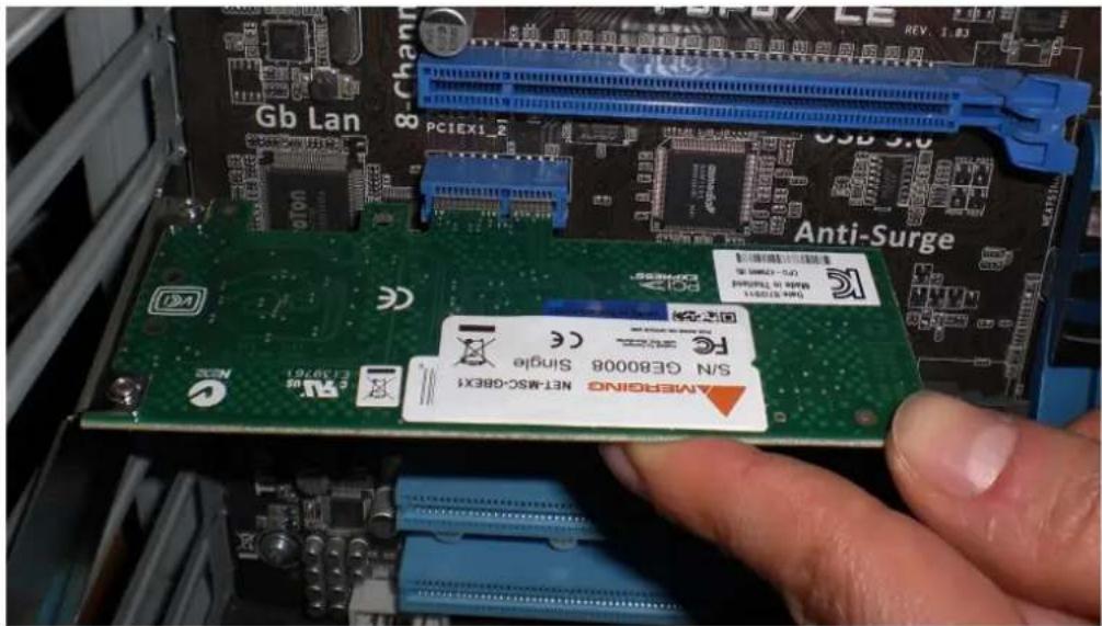
- Push down gently at first, ensuring you have the pins lined up correctly with the slot, and then apply more force to slot the card home fully.
- Use the screw which held the backing plate in place to secure the card and check that the card sits properly.
Finally, replace the case cover(s) and plug your machine back in.
- At "First Power Up" Windows will discover the Merging Ethernet PCIe card
Note: Refer to the Merging RAVENNA Configuration Guide for more details on the Pyramid MassCore-RAVENNA setup
HAPI MK II - Power ON
Connecting the Power Cable
The Hapi unit runs on 100-240V, 50-60 Hz AC voltage. Excessive voltages can seriously damage the Hapi unit, so make sure that your AC power matches the voltage of your Hapi unit. When you connect the power, use the cable you received with your Hapi unit and plug it into a grounded outlet.
For safety and EMC reasons, and to prevent audio hum, the system must be properly grounded. If your power source does not have a standard three-prong socket, the system must be grounded in another appropriate manner.
As an option Hapi can also be powered from a DC power source (10-14V), contact your local reseller about this option.
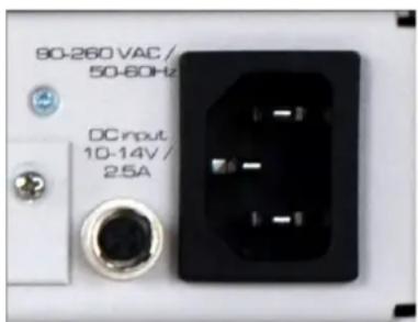
Hapi DC power input
Hapi can be delivered with a DC input capability, when this option is ordered a 4 pins connector (HR10A-7R-4S) is installed left to the AC power connector. The mating part which is also delivered is a Hirose HR10-7P-4P.
The pinout of this connector is:
- Pin 1: GND
- Pin 4: 12V
- Pins 2 and 3: not connected
The DC power input accepts voltages from 10V to 14V for a maximum power consumption of 30W.
As an option, Merging does also provide an external AC/DC 30W converter with the appropriate counter-part connector already mounted. Its product code is PSU-AC/DC-30W.

Hapi power up mode selection
The Hapi unit has been designed to have two power up modes selectable with a jumper on the backplane of Hapi:
- Normal operation: Requires to press on the power button to turn ON Hapi, pressing for more than 5 seconds on the same button will shut down Hapi
- Always ON operation: As soon as power inlet cable is plugged in the Hapi will power ON, pressing on the power button to either turn it on of off will have no effect
The selection of the mode can be done using jumper J13 on the backplane of Hapi.

Jumper J13 pinout:
- 1-2: normal operation
- 2-3: always ON operation
The default ex-factory setting is normal mode
Turn ON your Hapi
- Press the Hapi Front Panel Power Button

Note: Pressing small triangle will display the Home Page on the Hapi OLED.
Warning: The Hapi MkII firmware update differs from the Hapi 1 generation, since the update can be performed without a Maintenance mode start up. Refer to the MkII Firmware update section for details
-
The Hapi front panel button will turn on. If the panel button light isn't steady but appears to flicker, this may indicate a fault condition and requires immediate shut down.
-
Wait until the Hapi is fully started and displaying the Main Home screen.
Power Button color code.
Blue: Normal operational state
Yellow: Maintenance mode
Red: Firmware Update State - Do not abort
HAPI MKII - OLED screen interface
Hapi Menu Hierarchy
![graph TD A["MAIN"] --> B["Volume -11 dB"] B --> C["Input Levels: AES, A/D 1, MADI, Loopback, SPDIF"] B --> D["Output Levels: AES, D/A 2, MADI, Monitor, Loopback, SPDIF"] B --> E["Settings: 48kHz M Settings, Hot (PCM): -0.2 dB, Hot (DXD/DSD): 2.8 dB, Alignment: -18 dB, Decay Int. Time: 25 ms/dB, Peak…](/content/2026/05/903531/images/577449968fff126c9993d3b3d0f73ea9182e554be58c07aabba5322dc5a3278c.jpg)
Screen Navigation
The Main Rotary Control gives the user control over the Hapi OLED screen navigation

The Rotary Control:
The Rotary Control wheel when turned from right to left navigates through the available menu, to confirm a Menu entry Push the Rotary Control button. This will either open a sub-menu or confirm an entered value.
The Main Rotary Control also gives the user control on the volume level of the monitoring (Headphone or DA) or the gain level of a selected Mic PreAmp channel.
Push:
Pushing the Rotary button will confirm the menu entry selection or confirm an entered value.
Long Push: In order to return to the previous screen keep the Rotary Control pushed for 1 sec. Press hold a few times to return to the Home page.
Home Screen
This is the screen which you will see after the Hapi completes its boot sequence. From here you can navigate to all the other menus for the setup and use of Hapi. If at any time you want to return to the Home Screen, you can press and hold the Main Rotary Control button for a second in order to return to the Home Screen. The screen also has access to the 8 main sections of the Hapi menu: Volume, Meters, I/O, PreAmp, Setup, Presets, Errors and Exit.
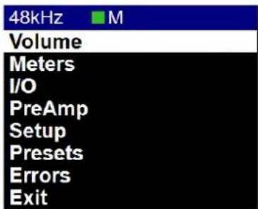

Pressing only the Home Page small pyramid button will bring the Hapi home page, this is applicable if no selection is active on the OLED
Volume Menu
The Volume menu is where the user can determine the analog output module which will be controlled by the Hapi Rotary Control. It will also display the output meters of the selected module.

Pressing the Hapi Rotary Control button allows user to select the which analog Module will be volume controllable

If you have multiple DA and would like to have both of them controlled by the Volume button simply select the DA1 + DA2 entry

Meters Menu
The Meters menu is where the user can view the metering of the Hapi available Input or Output modules.

A/D Meters Sub-Menu (Meters)
The A/D meters page displays a VU meter for each A/D Input available. If you have 1 x A/D module you will see 8 VU meters and with 2 x A/D modules you will see 16 VU meters, one for each physical input.
D/A Meters Sub-Menu (Meters)
The D/A meters page will display a VU meter for each D/A output available. If you have 1 x D/A module you will see 8 VU meters, if you have 2 x D/A modules you will see 16 VU meters, so one for each physical output.

Input Levels Sub-Menu (Meters)
The Input Meters page will display the input metering of the modules present in the Hapi. A metering view of one Led per input channel is represented in this page.


The LEDs indicate the inputs levels of the AD1 inputs 1 to 8
Note: You can reset a module Peak by pressing the Rotary Control. In the example above pressing A/D 1(8ch) will reset the peak displayed on the input 1. This led view ledged also applies to the DA view.
Output Levels Sub-Menu (Meters)
The Output Meters page will display the Output metering of the modules present in the Hapi. A metering view of one Led per output channel is represented in this page.

Meters Settings Menu

Hot: Sets the level above which the meter display will be red. If set to 0dB this will
mean clipping. Range -2dBFS to 0dBFS (PCM)
-2dB to 6dB SACD (DXD/DSD). Reminder: DSD users benefit from a +6dB
headroom in DSD with distortion starting slightly and progressively from
+3.1dB upwards and clipping once reaching +6dB SACD
Alignment: Sets metering level alignment range (yellow leds). Range -24dBFS to 0dB
Decay integration time: Sets the rate at which the level meter display decays after the level falls below the most recent Peak.
Peak Hold: If ON it will keep the red Peak Hold Overload in display
I/O Menu & Sync Sub-Menu (I/O)
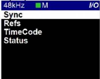
The IO and Synchronization menu is where the user can select the source of the Hapi reference clock. It is essential that these settings are configured correctly in order to ensure a clean audio signal through the Hapi unit.
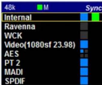
Reference Source Choose the desired sync source by selecting a Reference source.
Available Reference Sources are: RAVENNA, WordClock, MADI, AES or SPDIF
Reference navigation Selecting a Reference with multiple choices (such as Sync or AES) will enable the source navigation. The navigation is performed from top to bottom and will cycle through in this order at each consecutive press. The selection of another Reference Source will re-select the top entry in the list by default.
PTP Clock The Precision Time Protocol (PTP) is a protocol used to synchronize clocks throughout a computer network. Also known as IEEE 1588, it is a protocol designed to synchronize real-time clocks in the nodes of a distributed system that communicates using a network. RAVENNA is based on and uses
V2 of this IEEE standardized protocol. PTP Clocks allow for time resolution to the Nanosecond.
Master indicates that the current Hapi is the PTP Master
Slave: The Hapi is slave to another PTP Master
The Hapi will always try to be the PTP Master. If multiple Hapi' or Horus' are used in a network environment, the Hapi set in this order will have the PTP Master priority, using the Best Master Clock Algorithm (BMCA):
- Video sync
- Word Clock
- AES
- ADAT/SPDIF
- MADI
- PT64
-
Internal
-
RAVENNA (always slave unless there is no PTP master available)

Note: When two or more Hapi are connected together through an Ethernet network, one of them will always be automatically selected as master, the other Hapi' will be forced into slave state and therefore will not be synchronized to wordclock or audio input. However, this is not a problem since all Hapi' will be synchronized.
Status: LTC IN: Corresponds to the incoming LTC frame rate
Hapi PTP status: MASTER or SLAVE
Video Format Detected:
Supported Formats:
PAL - NTSC
720p23.98-720p24-720p25-720p29.97-720p30
720p50 - 720p59.94 - 720p60 (not recommended video formats)
1080i25 - 1080i29.97 - 1080i30
1080sf25 - 1080sf29.97 - 1080sf30
1080p23.98 - 1080p24 - 1080p25 - 1080p29.97 - 1080p30
PTP Master note: The GMID (Grand Master ID) is available from Web Access page under IO & Sync, and in the Advanced pages – PTP tab.
Refs Sub-Menu (I/O)
This Sub Page menu is where you can view the Deviation and Jitter of the External Reference, as measured by the Hapi synchronization circuitry.
![48k M Refs Sync src: AES - XLR1/2 Frequency: -100 0 100 48.000000 [kHz] 0.0 [ppm] Delta: -1000 0 1000 0 ms](/content/2026/05/903531/images/e0444093f4ae108b8200bdba4b0e9a5e34cfda0fb24bc68af64ccbf6131c9123.jpg)
Frequency: The long-term measured Frequency (in Hz) and deviation in ppm (parts per million) between the signal the unit is locked on to and the internal reference.
Delta: The short-term (instantaneous) time offset between the reference signal and the internal (considered as ideal) reference, measured in nanoseconds (ns). In other words, the delta indicator over a RAVENNA network will report the delta in ns between the master and the slave.
Timecode Sub-Menu (I/O)

IN Timecode: Will display the current incoming LTC/Timecode
OUT Timecode: Will display outcoming LTC/Timecode
Frame Rate: The current LTC/Timecode Frame Rate is indicated next to the Timecode IN & OUT display
From: Indicates the Timecode provider (in example above the Pyramid DAW)
Timecode Level: Shows the current LTC output level in dBu. The selector offers a choice of output level from -18dBu to +9dBu in 3dBu increments, or can be switched off
Mute on Stop: If OFF the LTC output will not be active (default) If ON the LTC output is generated constantly
Status Sub-Menu (I/O)
Lists the status of each Module Channel count (I/O) and each module Mode (Example: PCM or DSD modes)
| 48k | M | Status |
| AES | (8ch) | PCM |
| A/D 1 | (8ch) | PCM |
| D/A 2 | (8ch) | PCM |
| MADI | (64ch) | PCM |
| Monitor | (2ch) | PCM |
| Loopback | (8ch) | PCM |
| SPDIF | (2ch) | PCM |
PreAmp Menu
The PREAMP (A/D) menu becomes active if you have 1 or more AD8(P) modules installed in the Hapi unit, giving full access to the Input controls. Please see below for a description of the buttons available.
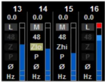
All Active: Will select all 8 input channels for function and level grouping
Inactive: Adjustments to the input settings and level affect only the selected channel only
Note the All button will group all inputs of the same type (Mic or Line)
Gain slider The Rotary Control will give the user control over the Gain level with
increments/decrements in 0.5 dB steps
The Gain range goes from 0 dB to +66.0 dB from left to right
In Mic mode (M): Sets the Mic Preamplifier's Gain
In Line mode (L): Sets the Line Input Sensitivity
A value of 0dB corresponds to an input sensitivity of +24dBu for 0dBFS. This corresponds to a calibration level of +4dBu for -20dBFS.
A value of +20.0 dB corresponds to an input sensitivity of +4dBu for 0dBFS A value of +66.0 dB corresponds to an input sensitivity of -42.0dBu for 0dBFS
Example: Assuming you want to interconnect to an analog console and your standard studio alignment level is +4dBu for -18dBFS. In this case set the gain slider to +2dB. Similarly, on the DA analog output side, set the attenuation to -2dB, refer to section Line Output Level calibration on page 22, provided the max output level is set to +24dBu.
Mic (M) or Line (L) Switches the Input from the Mic-Pre amplifier to the Line level circuitry. The
button will show the current input signal path it is set for (Mic or Line).
The Line input sensitivity can be adjusted by setting the line gain for each input of the AD module.
Line Fader of 0 dB, means 0 dBFS for +24 dBu Analog signal level present at the Line input
Line Fader of +6 dB, means 0 dBFS for +18 dBu Analog signal level present at the Line input
Line Fader of +20 dB, means 0 dBFS for +4 dBu Analog signal level present at the Line input
Line Fader of + 66 dB, means 0 dBFS for -42 dBu Analog signal level present at the Line input
Note #1: the MIC and Line inputs are stored as independent parameters, meaning that switching from Mic to Line and vice versa will load its own gain (sensitivity) value
Note #2: The Premium AD converters have been designed in order to be able to benefit from the +3.1 dB SA-CD headroom offered by DSD, as per the scarlet book standard. The gain range goes from +0dB to +66dB in both PCM and DSD mode. In DSD mode it is possible to set a gain of up to +6dB on a full-scale signal to benefit from the SACD headroom.
48V This button will turn on 48V phantom power for the channel. If it is lit, it means that Phantom power is active. Only active on channels set to Mic.
The total current drawn on the phantom power by all the microphones should never exceed 48mA for the whole device
If a MAJOR (by MAJOR, we mean that the threshold of short-circuit detection requires at least 10 Preamp inputs to be shorted simultaneously) 48V Phantom Power Supply short circuit is detected, 48V is forced off on all A/D channels and the following error message is displayed.
"48V power failure: all A/D 48V forced off until next reboot"
This warning applies ONLY to the initial RUN 3 production batch of AD8 and AD8P and has been fixed for all modules shipped starting November 2012: The 48V power MUST be turned off prior to changing the connection in certain patch bays. Many such patch bays do short the Hot, Cold or both signals to Ground during insertion or removal of the Jacks with the risk of deteriorating permanently the protective resistors in the input of the PreAmp circuitry. If an AD module input circuitry is damaged, following such a short, it will end up permanently having inaccurate gain levels, distortion or even no signal at all on some channels. That would require hardware replacements at your own cost, since such damage is not covered by our warranty. If you still own one of the original and unmodified RUN 3 AD8/AD8P modules we recommend that you contact your Merging reseller to organize an update of your module(s), which Merging is pleased to provide free of charge.
Zlo – Zhi Mic input impedance (only available for ADA8, AD8D/AD8DP run 9 and above) and AKD8D/AKD8DP modules.
For the different mic input impedance values, please refer to the card specifications.
PAD (P - B) A -10 dB Pad can be applied in the Mic Preamp circuitry. B- Boost: Increases the mic input signal level by 12 dB > Max input level 0dB Note: The Boost is only available for the modules ADA8S and ADA8P Recommended for Ribbon Microphones that have low output.
∅ Polarity invert button. When lit, it inverts the polarity of the selected input signal.
80 Hz (Hz) Low cut filter 80 Hz. Second order, 12 dB/octave.
Meters dB scaling The Meters scaling is displaying from -90 dBFS to 0 dBFS.
Meters color range Refer to the Meters Page Settings, in order to adjust the Level meter color range (Peak, Alignment and Decay time).
Rst Stands for Reset Peaks Hold Meters. The top Red led of the PreAmp metering will indicate that a Peak has occurred. In order to clear the Peak display, simply press the RST button on the remote web access. To reset the peaks on the OLED you must refresh the PreAmps Page by going to previous one and back. Enabled the Peak Hold option under the Meters menu Settings
Navigation Use the left << and right >> arrows in order to navigate through the banks of 8 inputs. Will be active if more than one AD8(P) module is present in the unit.
Setup Menu
The Setup menu's primary page contains function buttons described below as well as sub-menu links listed in the sub-sections; Formats, Routing, Modules, Presets, System, Network and Info

Formats Menu (Setup)

Sample Rate: Select the Hapi Sampling Rate
44.1 kHz - 48 kHz - 88.2 kHz - 176.4 kHz - 192 kHz - 384 kHz - DXD/DSD Note: The available Sampling Rates depend on the Hapi Analog module cards. Only Premium Analog modules offer support beyond 192 kHz.
Auto Auto Sampling Rate mode. Hapi will automatically follow the sampling rate given by a RAVENNA source provided by; ASIO / Virtual Audio Device (Formerly Core Audio Driver), MassCore or another Horus/Hapi) or external Input Sync source.
Example 1: User using an external player (such as jRiver) can enable the Auto mode so that Hapi automatically changes its sampling rate according to the media file being played back. Provided at least one RAVENNA ASIO or Virtual Audio Device (formerly Core Audio) stream is connected to an Output of the Horus/Hapi
Example 2: This Auto setting can apply to user running the RAVENNA ASIO or Virtual Audio Device (formerly Core Audio) so that Hapi adapts its sampling rate automatically. Provided at least one RAVENNA ASIO or Virtual Audio Device (formerly Core Audio) stream is connected to an Output of the Horus/Hapi
Example 3: Another usage of this « Auto » sample rate button is to enable the Horus/Hapi locked (e.g. WordClock) to automatically follow the sample rate of the WordClock generator (same applies to AES/MADI/ADAT sync). Provided at least one RAVENNA ASIO or Virtual Audio Device (formerly Core Audio) stream is connected to an Output of the Horus/Hapi
Warning: The Auto sampling Rate option must be disabled if locking the Horus/Hapi devices to reference (e.g. 44.1kHz WordClock) which would be different than the working Sampling Rate Format (E.g. 88.2kHz,,192kHz, DXD.) For MADI, the Auto sampling rate option depends on the MADI framing (48 or 96k frame). Therefore it is recommended to disable the option at sampling rates higher than 48 kHz.
Note: If using ANEMAN with a Sampling Rate Zone the device on the Crown will decide the Master sampling rate of all the devices present in the Zone. In such a case it is recommended to disable the Hapi MkII Auto Sampling Rate mode to avoid fights over the sampling rate of the non-Crowned devices at a given moment, since those could potentially cause sampling rate flickering.
A/D Mode in DXD/DSD: This format setup only applies to the AD module which can be set to either DXD - DSD64 - DSD128 - DSD256
Note: The Hapi can be configured in DXD/DSD and in this mode the Hapi can receive any audio data format stream and can generate DXD or DSD(64, 128 or 256) stream depending on the A/D audio data format chosen.
WordClock Output: 44k1 / 48k: When enabled the Wordclock Output will be at either 44.1kHz or 48kHz
Example:
Sampling Rate: 44k1/88k2/176k4 the WordClock Output will be 44.1kHz Sampling Rate: 44k/96k/192k the WordClock Output will be 48kHz.
Follow SR: When enabled the WordClock Output will follow the Sampling Rate selected.
Example:
If the selected Sampling Rate is 48k the WordClock output will be at 48kHz If the selected Sampling Rate is 176k4 the WordClock output will be 176.4kHz
Pull Up/Down: Slow down or accelerate audio clock by 0.1 % depending of the frame rate of the video reference.
This option will only be active if the sync source is configured to Video Ref. The Status of this option can be viewed in the IO&Sync page under Status - Off: Normal operating mode
- Up: Accelerate the clock by 0.1%. Supported only with a Video reference at 24fps and 30fps
- Down: Slowdown the clock by 0.1%. Supported only with a Video reference at 23.98fps and 29.97fps
Routing Menu (Setup)
Module routing menu describes where the signal for each module in the Hapi is coming from. Each button leads to a sub-menu that allows the user to change the source of the signal to that specific module. For instance, the Headphone in the Routing menu will allow the user to change the routing of the Headphone.
Choices are made in blocks of 8 channels from the OLED (except for the Monitor, which is a Stereo signal). As of the Hapi MKII single channel routing is supported but has to be performed via the RAVENNA Advanced pages. For more information refer to the Advanced Pages online guide. https://merging.atlassian.net/wiki/spaces/PUBLICDOC/pages/4819571/Merging+RAVENNA+Advanced+Pages+User+Guide.
Note: The Hapi MKII is different from its predecessor Hapi and Horus since it is based on a routing architecture, each routing performed remains exclusive but without automatic stream connectivity. So, following an internal routing if the operator decides to revert to its preceding RAVENNA routing this one will have to be reconnected in ANEMAN to stream back audio.

Here the AD8 module is routed to the DA8 module and it will remain available for RAVENNA routing
ADAT: Takes you to the ADAT Routing configuration page (refer below)
AES: Takes you to the AES Routing configuration page (refer below)
D/A: Takes you to the D/A Routing configuration page (refer below)
PT64: Takes you to the PT64 Routing configuration page (refer below)
MADI: Takes you to the MADI Routing configuration page (refer below)
HEADPHONE: Takes you to the Headphone Routing configuration page (refer below)
SPDIF: Takes you to the SPDIF Routing configuration page (refer below)
A/D: Disabled as one cannot route TO an Input!
Loopback: Takes you to the Loopback module (present only in debug mode)
Warning: Two inputs can't be routed to the same output, as we are routing channels and not mixing.
Routing: Source Configuration
ADAT - AES - D/A - MADI - SPDIF Routing Output Source (similar)

For all of the output modules (ADAT/SPDIF,AES, D/A N, PT64, MADI & Headphone Jack) the user can set where the signal feeding it comes from. Any combination is possible using the Output source page linked to any of the output modules.
* All routing in the Hapi is currently achieved using banks of 8 channels.
Unrouted: No internal routing has been performed, the module remains available for RAVENNA and/or internal routing
ADAT/SPDIF: Sets the module being configured to receive signal from the ADAT/SPDIF
AES: Sets the module being configured to receive signal from a bank of AES-EBU inputs.
MADI: Enables the module being configured to receive signal from any 8-channel bank in either of the MADI streams
PT N: Enables the module being configured to receive signal from any 8-channel bank in either of the PT64 modules.
A/D N: Sends the signal coming in from the Mic or Line input modules to the output module being configured
Loopback: Should only be used for test purposes.
Routing Example:
MADI Routing Output: Users can route literally any input signal to any output module. Users can also route any input signal to any combination of output modules. Signals are routable in blocks of 8 channels.
The example picture below shows the MADI output1-8 routing being selected from the Routing page on the ADA8 module channels 1-8


With Hapi MKII single channel routing is supported but has to be performed via the RAVENNA Advanced pages. For more information refer to the Advanced Pages online guide. https://merging.atlassian.net/wiki/spaces/PUBLICDOC/pages/4819571/Merging+RAVENNA+Advanced+Pages+User+Guide.
Modules Menu (Setup)

Selecting one of the Modules described below will open the Module I/O configuration menu
AES
Included as standard. The AES buttons are active since this module is included as standard. Connectivity is over 1 D-SUB25 connectors providing 8 channels (4 AES pairs) of AES-EBU I/O.
Headphone
Shortcut to the Headphone monitor page described above.
D/A N
The D/A buttons become active when 1 or more IOC-DA8(P) modules are installed in the Hapi unit.
Trim : Headphone / DA N / ADA N
Hapi MKII provides single channel trim support.
A/D N / AKD N
The A/D buttons, which become active if you have 1 or more AD8(P) modules installed in the Hapi unit, give access to the Input controls. N being a number incrementing from 1 to 2. Please see below for a description of the buttons available.
ADA N
The ADA buttons, which become active if you have 1 or more ADA8 or ADAv2 modules installed in the Hapi unit, give access to the Input controls.
PT N
The PT buttons become active when an IOC-H-PT64 module is installed.
MADI
MADI module is optional with each Hapi. Only one MADI module can be fitted per Hapi.
TimeCode
Included as standard. The TimeCode button is active since this module is included as standard and will bring you to the TimeCode page.
ADAT/SPDIF
ADAT/SPDIF module is included as standard with each Hapi.
Headphone Menu
The Headphone menu refers to the Hapi front panel Headphone Monitor jacks. The Headphone jacks 1 & 2 (6.3 mm and 3.5 mm) output the same source and level.

Attenuation: Sets the attenuation of the Headphone output. By selecting (Rotary Push) the Attenuation entry and using the Hapi Rotary Control (Left= less gain / Right= more attenuation) to set the attenuation to the desired level
Headphone level range: -60 dB to +12 dB with 0.1dB precision.
Headphone Mute: Mutes the headphone output when ON is enabled

Roll off Filter:
Slow (default): Offers the lowest latency of 9 samples, with the tradeoff of a gentle frequency response attenuation reaching -3dB at 0.45 x FS (21.6 kHz @48k)
Sharp: Offers a flat frequency response with an attenuation of 3 dB at 0.484 x FS (23.2 kHz @48k), which has the tradeoff of 35 samples latency.
Apodizing: Fast Roll-Off filter, Linear phase filter. Latency of 35 samples
Brickwall: Ensures rejection of more than -100dB at Nyquist (0.50 x FS, 24 kHz @48k). Latency of 35 samples

TRIM: Headphones

Open the Trim Headphone page in order to have trim level per channel support. The headphone module offers 2 channel trims (left and Right) on a .1 dB step scale. With a per channel polarity parameter and a two channels one.

AUDIO FOR THE NETWORKING AGE
MERGING

Modules: MADI Sub-Menu
MADI module is optional with each Hapi.

Mode: Sets the MADI mode to either "Standard" (56 audio channels) or "Extended" (64 channels). To determine which setting(s) you are able to use, please consult the user manual of the device you are connecting the Hapi to in order to see which (if not both) formats it complies with.
Note: MADI Standard (56) can only be enabled at 1FS (44.1kHz/48kHz) above 1FS we will automatically revert to MADI Extended (64).
Physical Mode: Choose the input signal to be derived from the Coaxial or Optical MADI connections at the back of the Hapi unit. You can choose to use either or, but not both at the same time
Output Mirror Choose if the output MIDI signal goes out from the Coaxial and Optical MADI at the same time, thus is mirrored. Available as of firmware 1.5.7 and above.
Legacy/High Speed: Choose between using Legacy (48k Frame) or High-speed (96K to 192K Frame).
This option is only available for MADI output at 88.2/96kHz sampling rate and 176.4/192kHz sampling rate and is dependent of the device used in conjunction with the Hapi
Note: Mykerinos users who are connected to the Hapi should configure their Mykerinos Pyramid general settings so that the MADI High Speed mode is disabled and then set the Hapi to 48k Frame (legacy).
Modules: A/D Sub-Menu
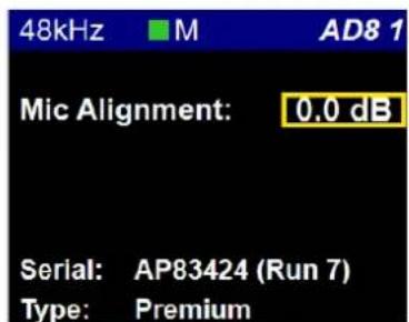
Mic Alignment: User can offset the Mic Gain Alignment scaling from a Range of 0dB to +12dB.
Example: Setting a gain alignment of +10dB will make the Hapi, Web Access or the Pyramid PreAmps control to be offset by a scaling of +10 dB.
Serial Number: This is the place you can access all your Modules serial numbers without having to unslot them or open the box
Type: Module Type description (Example : Premium Direct Out)
Modules: ADA Sub-Menu

Mic Alignment: User can offset the Mic Gain Alignment scaling from a Range of 0dB to +12dB.
Example: Setting a gain alignment of +10dB will make the Hapi, Web Access or the Pyramid PreAmps control to be offset by a scaling of +10 dB.
Max Level Maximum Output Level: +18 dBu or +24 dBu
Output attenuation: Calibration of the D/A output (Range -60.0 dB to 0 dB with 0.1 dB precision). Refer to the Hardware section for the D/A onboard output level calibration.
Roll Off Filter: Recent ADA8S/P modules offers 4 roll off filters: Slow, Sharp, Apodizing and Brickwall. Refer to the ADA8S/P Module section at page 31 for more details
Previous ADA module offer 2 Roll Off filters. Sharp or Slow.
Sharp roll-off filter: Offers a flat frequency response up to 22kHz, within 0.2dB, which has the tradeoff of 36 samples latency.
Slow roll-off filter: Offers a low latency of 9 samples, with the tradeoff of a gentle frequency response attenuation starting around 16kHz and reaching -2.5dB at 22kHz. This mode is the default one.
Serial Number: This is the place you can access all your Modules serial numbers without having to unslot them or open the box
Type: Module Type description
Modules: D/A Sub-Menu

Max Level: On the DA8 and DA8P cards, the output level setting for all channels is done via software through the option "max output level" in each DA's setting page, allowing either +24 dBu or 18 dBu max level.
For a more precise trimming of the output level, the output attenuation can be set on the same page
Output attenuation: Calibration of the D/A output. Range -60.0 dB to 0 dB with 0.1 dB precision steps Refer to the Hardware section for the D/A onboard output level calibration.
Mute: Mutes all the DA output channels when ON is enabled

Roll Off Filter: Sharp roll-off filter: Offers a flat frequency response up to 22kHz, within 0.2dB, which has the tradeoff of 36 samples latency. This mode was and still is the default one. Slow roll-off filter (default): Offers a low latency of 9 samples, with the tradeoff of a gentle frequency response attenuation starting around 16kHz and reaching -2.5dB at 22kHz
Serial Number: Module serial numbers
Type: Module Type description
TRIM: DA

Open the Trim DA page in order to have trim level per channel support. The DA module offers 8 channel trims, from channel 1 to channel 8 on a .1 dB step scale. With a per channel polarity parameter.
Modules: PT64 Sub-Menu


Emulation mode: Selection of the Hardware emulated in Pro Tools. Latency is adapted to the mode chosen, see detailed table in IOM-H-PT64 section.
None mode is seen as an HD MADI in Pro Tools, but has the lowest latency.
Serial Number: Module Serial Number and Run
Output Source: Selection of the output source sent to Pro Tools for each of the 8 groups. Any of the digital or analog inputs can be routed to Pro Tools as well as RAVENNA signals.
Modules: Loopback (hidden menu, available only for debug use)
Transparency Check: This is a Debug Utility tool that verifies the bit transparency of the audio path
On: Transparency check enabled
Off: Loopback mode enabled
Word Length: Word length of the digital audio data signal (16 bits or 24 bits)
Status: Green: Path transparency valid
Black: Path is not transparent
Numbering: indicates the number of discontinuities measured
Latency: Output to Input delay in samples
Presets Menu (Setup)

Load: 5 presets banks of different Hapi configurations can be loaded (one at a time)
Save: 5 presets banks are available to store different Hapi configurations
Auto Save: If enabled the save configuration will happen at every 2 minutes.
Note: Since the flash memory which is at the heart of the Hapi storage has a huge (but not infinite) amount of write cycles, we limit the auto-save of all configuration and PreAmps settings to once every two minutes if (and only if) a change has occurred meanwhile.
Furthermore, both Shutdown and Reboot buttons (in Setup page) do also entirely save the current configuration of the Hapi prior to power down.
System (Setup):
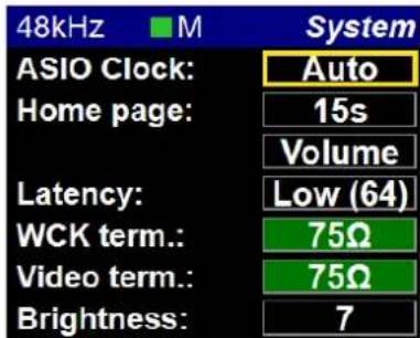
ASIO Clock: If set to Auto enabled: The ASIO clock will be generated by the Hapi which will be PTP Master.
If Auto is disabled: The ASIO clock will always be generated by this Hapi.
Note: Do not disable unless you are sure that no Hapi will be PTP Master.
Home Page: Users can decide what will be their Hapi OLED Home Page. You can return to the Home Page by performing consecutive 1 sec push hold or by pressing and releasing the Hapi front panel Home Page button (small Pyramid). Users can also set a Home page display delay option of; 15 seconds, 30 seconds, 1 minute or set it to Never (disabled).
A/D Metering: The screensaver redirects you to the AD Meters Page.
D/A Metering: The screensaver redirects you to the DA Meters Page.
In Levels: The screensaver redirects you to the Input Level Page.
Out Levels: The screensaver redirects you to the Output Level Page.
Volume: The screensaver redirects you to the Volume Page.
Long push the Rotary Control to exit those pages.
Screensaver: The Hapi screen will turn black after a 1min delay without user interaction. This is in order to preserve the life span of the Hapi OLED display. To exit the Screensaver press the Rotary Control Button.
Latency: The Hapi has 4 Latency Settings (in samples) that will determine the device latency over a RAVENNA network. When multiple RAVENNA devices (e.g. Horus & Hapi) are connected over a network, they adjust themselves to the lowest latency that can globally be achieved.
- Ultra Low (16 smp)
- Extra Low (32 smp)
- AES 67 (48 smp)
- Low (64 smp)
Terminations: 75Ω for WCK: Sets 75Ω termination for the Wordclock Input. 75Ω for Video: Sets 75Ω termination for the Video reference Input. Unless the Video Reference signal provided to the Hapi is daisy-chained to other equipment, you should always terminate your Video signal for most reliable operation.
Brightness: Users can set the Hapi Power Button and OLED display luminosity. This may save some power and hence some internally generated heat.
Note: during the adjustments the OLED will flicker black and update the brightness value.
Network Menu (Setup)

Device Name: Name of the Hapi unit. This name will be broadcast across the network and will be seen in applications such as the MT Discovery tool or ANEMAN. The Hapi unit name can be changed from the Web control access Network page (see section below for all details)
IP Settings: Manual: Type IP address using box selection and the - or + buttons Auto: The IP address will be automatically attributed using ZeroConf/Auto-IP mechanism (address range 169.254.xx.xx if no DHCP server is present)
Address: Set the IP Address for the Hapi unit by using box selection and the - or + buttons (Available only with IP Settings = Manual)
Netmask: Set the Subnet Mask for the Hapi unit by using box selection and the < or > buttons (Available only with IP Settings = Manual)
Apply & Reboot: Once changes have been made to this section, you must press this button to save the settings and power cycle the Hapi unit
Note: Hapi has no DHCP-server capability neither does the Merging PCIe Ethernet Controller Card NET-MSC-GBEX1. By default the Hapi IP setting is set to "Auto" configuration mode which gives an address in the range 169.254.xxx.xxx if no DHCP server is present on the network. Users are free to put a DHCP server in their RAVENNA network with a customized address range and the Hapi would get an IP address from this server. Note that our recommended RAVENNA switches are configured with DHCP disabled.
Merging recommend the Hapi to be configured in "Auto" mode and the Merging PCIe Ethernet Controller Card NET-MSC-GBEX1 to also be configured with "Internet Protocol Version 4" with "Obtain an IP automatically".
The Hapi MKII RAVENNA provides two network operation modes.
1- ST2022-7 Seamless Protection Switching
2- Network Switch mode (default). Allowing daisy chain for an extra network device
Those modes of operation are available for selection from the RAVENNA Advanced Pages. Find more details here.
https://merging.atlassian.net/wiki/spaces/PUBLICDOC/pages/4819571/Merging+RAVENNA+Advanced+Pages+User+Guide.

Info (Setup):
In this sub menu you will find details about the Hapi internals; temperature, serial number and the firmware version currently installed.
![48kHz ■ M Info Temperature: 47 [°C] Unit serial: H95041 ZMAN serial: 10289152 Version: 1.0.0b28910 Maintenance: 16](/content/2026/05/903531/images/1c62120504c784ed4730706bcdac920f97c409b05d75ff5ac7eb79dd501eab03.jpg)
ERROR Menu
List the errors detected by the Hapi. Refer to the troubleshooting section below for details of each errors. The Clear entry will delete the listed errors.

EXIT Menu

Shutdown: Initiates a proper shutdown of the Hapi unit, including a save of the current configuration. Do not attempt to shutdown the Hapi unit in other ways (such as using the power switch on the back of the device).
Reboot: Power cycles the Hapi unit (shutdown>Boot up)
Reboot to Factory: If selected we will reboot the Hapi to the default factory configuration. The Current configuration will be lost but all the saved presets will be kept and can be reloaded.
HAPI MKII - Web Control Access
Installing and accessing the Hapi Control interface remotely
To control and view your Hapi remotely with a web browser make sure that you are using one of the Internet browsers below: Google Chrome (Highly Recommended), Mozilla Firefox, Opera, Apple Safari, Microsoft Edge. * Microsoft Internet Explorer is not supported *
Then take the following steps:
1) If you did not install Pyramid or Ovation proceed from step 2 to 3. If you have already installed a Pyramid / Ovation go directly to step 4)
2) Download either ANEMAN or the MTDiscovery.exe application to your system (PC or MAC installers are available)
https://www.merging.com/products/interfaces/downloads
3) Make sure your Hapi is connected to the same network as your system, and is configured with the correct IP settings (See "Setting up the Hapi IP Address")
4) Launch the MT Discovery tool (MTDiscovery.exe) or ANEMAN (Aneman.exe)
Any Hapi devices on the network will be discovered by the MT Discovery tool or ANEMAN and will appear under the "RAVENNA Devices"
- A mouse double-click on the Hapi Device entry will open the Hapi Web Interface in your default web browser
- Only Devices on the same network (same color in display) can have their I/O interconnected
- *Microsoft Internet Explorer is not recommended for this*
MT Discovery Window
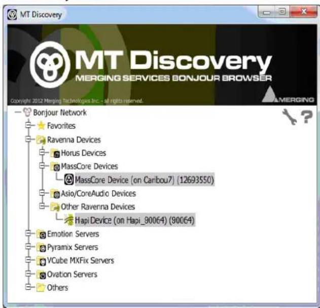
ANEMAN

Using the Webpage, you can browse the Menus and change parameters in exactly the same manner as on the front panel TFT of the Hapi unit in question.
Warning: It is mandatory that you connect the Hapi to a Gigabit Ethernet Port or Switch for remote access.
HAPI MKII Web Access
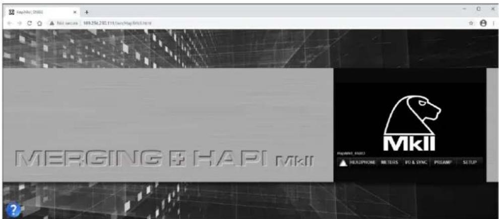
The Web access Hapi MKII menu pages are based on the Horus layout and differ from the Hapi MKII OLED screen. For precise description of each parameter refer to the Hapi MKII OLED description of the parameter as the Web Access is remote controlling the same parameters that are available on the Hap MKII OLED display.
Home Page Web Access
The Hapi remote Home page is the default web access page displayed at opening and is different from the Hapi OLED home page display.

HOME PAGE LAYOUT ENTRIES
HEADPHONE
Direct access to the Headphones pages

METERS
The Meters web menu will display the input and output metering of the modules present in the Hapi.
At the top of the Meters Web Access page is the Stream Metering section which provides metering of your RAVENNA/AES67 AoIP streams, this section is divided in two.
Receivers (Channel 1 to 256)
Senders (Channel 1 to 256)
Note: this section is useful to identify if audio is being streamed, if you see metering and cannot monitor your signal, the problem is mostly probably a routing one.

Led indications:
Peak indication
Alignment range
Signal indicator
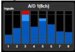
The leds indicate the inputs levels of the AD1 inputs 1 to 8
Note: You can reset a module Peak by doing Mouse + Click on the Module display section. In the example above pressing A/D 1(8ch) will reset the peak displayed on the input 1.
Meters web Settings:

Hot: Sets the level above which the meter display will be red. If set to 0dB this will mean clipping. Range -2dBFS to 0dBFS
Alignment: Sets metering level alignment range (yellow leds). Range -24dBFS to 0dB
Decay integration time: Sets the rate at which the level meter display decays after the level falls below the most recent Peak.
Peak Hold: If ON it will keep the red Peak Hold Overload in display
IO & SYNC Web Access
The IO and Synchronization menu is where the user can select the source of the Hapi reference clock. It is essential that these settings are configured correctly in order to ensure a clean audio signal through the Hapi unit. Refer to the OLED IO & Sync description for more details.

REFS
Timecode: Required Sync cable connectivity
![Sync Source: RAVENNA | Frequency | Value | | :--- | :--- | | -100 | 252.400917 [-6-tz] | | 0 | 2.58 [ppm] | | 100 | 1000 [cm] | | 10000 [cm] | 10000 [cm] | | Delta: | 141 ns | < I/O & SYNC Refs](/content/2026/05/903531/images/52385d19690db17957431b9865d985233937ea50566737e4ef6b80d0c6029288.jpg)

PreAmp Web Access
- Allows the creation of up to 8 groups
■ Naming of channels (can be saved in Hapi presets) - VU meters
For other parameters, please refer to the PreAmps module description (above)
Note: The Boost PreAmps option available only for latest generation of ADA8S and ADA8P modules
Preamp web menu
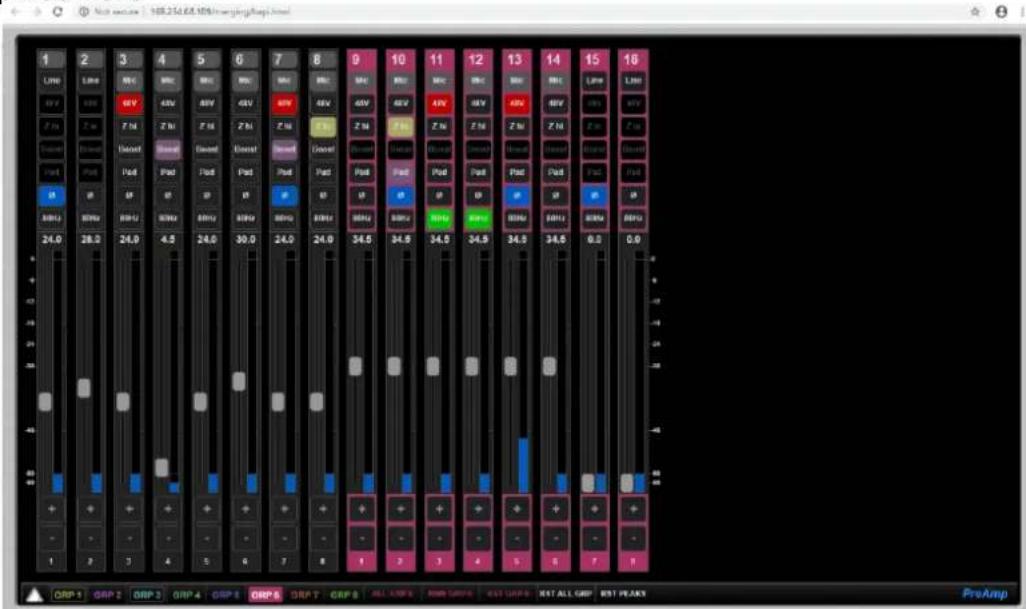
ALL GRP Will include all faders into the selected group
RMN GRP Will include the remaining faders into the selected group
RST GRP Will reset the selected group
RST ALL GRP Will reset all groups, all grouping will be reset to default
SETUP Web Access
The Setup page once opens will bring you additional sub parameters pages and controls
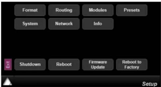
Format
Sampling rate selection, Auto sampling rate and more. Refer to the OLED Format description
Routing
Remote routing access page, where available modules will be displayed for selection. Refer to the OLED Routing description
Modules
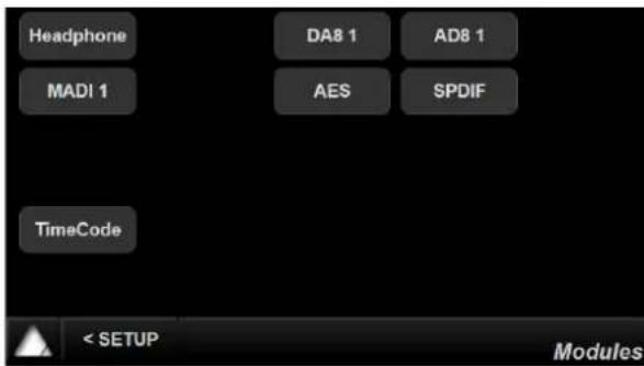
Module menu will show the available Hapi Modules that your Hapi has in its configuration. Each module type has its own set of parameters.


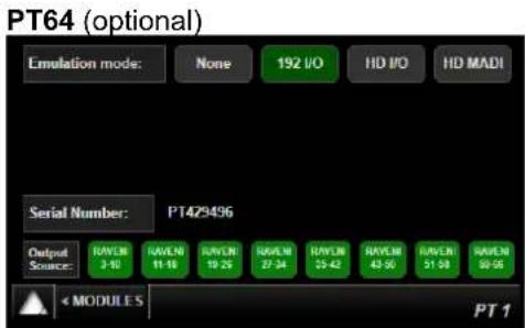
PRESET Web Access
Disk Presets can be stored and loaded on your local system where Hapi is connected to.

Save Presets Up to 5 presets can be saved and stored in the Hapi
Load Presets Up to 5 presets can be loaded from the Hapi
From Disk Users can load some presets that were stored on your local Hard Drive
To Disk Users can save some presets to your local Hard Drive
Reboot to Factory Will reset all the Hapi parameters to the default factory settings
Note: Stored Hapi preset have a .bin file extension. In order to be able to rename the Hapi preset file at save the Chrome browser users will need to adjust this Setting.
-
Go into Chrome Settings
-
Click on Show advanced settings
-
Under Downloads, check the box « Ask where to save each file before downloading »
Now when clicking on « to Disk » a window pops up that allows you to change the name of the preset (.bin) file prior to saving it.
Settings
Passwords and forms
√ Enable Autofill to fill out web forms in a single click. Manage Autofill settings
√ Offer to save passwords I enter on the web. Manage saved passwords
Web content
Font size:
Page zoom:
Medium
Customize fonts...
100%
Network
Google Chrome is using your computer's system proxy settings to connect to the network.
Change proxy settings...
Languages
Change how Chrome handles and displays languages
Languages and spell-checker settings...
√ Offer to translate pages that aren't in a language I read
Downloads
Download location: C:\Users\mt-build\Downloads
√ Ask where to save each file before downloading
Change...
Note: When saving presets to Disk with the Chrome Brower it is possible that the save windows dialog does not show up. It such case it is due to the browser Pop-Up blocker configuration. Make sure that you allow pop-ups from your Hapi.
The following pop-ups were blocked on this page:
Loading...
Always allow pop-ups from horus_80059.local.
Continue blocking pop-ups
Manage pop-up blocking...
Done
NETWORK Web Access
Hapi network configuration page

The Hapi MKII RAVENNA provides two network operation modes
1- ST2022-7 for Seamless Protection Switching
2- Network Switch mode, allowing daisy chain for an extra network device
Those modes of operation are available from the RAVENNA Advanced Pages. Find more details here. https://merging.atlassian.net/wiki/spaces/PUBLICDOC/pages/4819571/Merging+RAVENNA+Advanced+Pages+User+Guide.
SYSTEM Web Access
Refer to the OLED System description.

INFO Web Access
In this sub menu you will find details about the Hapi internals; temperature, serial number and the firmware version currently installed
![Temperature 59 [°C] Unit serial: H95003 ZMAN serial: 121498 Firmware Version: 1.2.0b46052 < SETUP Info](/content/2026/05/903531/images/943a58edc600e1cd991070d870d7872abf41fe305d79962938cded6b6413708c.jpg)
EXIT Web Access

Shutdown: Initiates a proper shutdown of the Hapi unit, including a save of the current configuration. Do not attempt to shutdown the Hapi unit in other ways (such as using the power switch on the back of the device).
Reboot: Power cycles the Hapi unit (shutdown>Boot up)
Firmware Update: Will open the Firmware update browser page. Refer to the Firmware update procedure for more details
Reboot to Factory: If selected we will reboot the Hapi to the default factory configuration upon confirmation. The Current configuration will be lost but all the saved presets will be kept and can be reloaded.
Identify Me – Device Location
The Identify me feature is available to locate a device over a network. If you have multiple network Interfaces over a network you might at some point identify one of them. The identified device will then blink so that you can locate it.
Procedure
- Open the Hapi MkII advanced pages.
This can be done form the Driver (MAD or VAD) or from MTDiscovery by Mouse+Right clicking on the Hapi icon and open the Advanced Pages. - Once the Advanced pages are open go to the top right of the page
- Check the Identify Me box

- This will identify the Hapi MkII (or Anubis) and make the Hapi MkII Power button blink
You have now identified your device over the network.
HAPI MKII embedded User Manual
The Hapi embedded User Manual can be opened by clicking on the question mark sign at the bottom left of your browser. This will overlay the Hapi User Manual on your Web control access page.
Figure5 HAPI MKII Embedded User Manual

Disconnection Warning - Web Access
User will be warned it the remote web access to the Hapi become offline/disconnected.
Hapi Web Access Disconnected
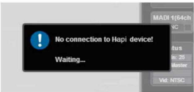
HAPI & HORUS Setup Examples
RAVENNA Network For DSD256 Mix/Record With Backup Recorder
Stage Equipment
1xIOC-HORUS with a total of
• 6xCAD8P Premium AD cards (48 Channels)
Mix/Recording Room
• MassCore Pyramid Recording System
• PSI A215M reference monitors
- Tango2 Control surface
• Secondary Audio Device over USB/PCIe
• Talkback Microphone
Backup Recording/Editing Rig
• MassCore Pyramid Recording system
- Secondary ASIC Device (USB)
![graph TD A["Live Room Mics"] --> B["Live Room"] B --> C["ASIO Device"] C --> D["Confidence Monitoring"] E["CONTROL ROOM"] --> F["Gb Switch"] F --> G["MassCore"] F --> H["RAVENNA"] G --> I["SlateMic: XLR"] H --> J["ASIO Device"] I --> K["Speaker Lines: XLR"] J --> L["Oasis Control: CAT5"] K --> M["AS…](/content/2026/05/903531/images/19f193f9c925253714ad869d8ffd6b97ad2c8399c74b824239d24589cb1fd955.jpg)
RAVENNA Network For Mix/Record and Live transmission of multichannel performance
Stage Equipment
1xIOC-HORUS with a total of
- 6xAD8P Premium AD cards (48 Channels)
• 1x DA8 Standard DA card swap out card
for one of the AD cards to provide a 40/8 configuration (if needed)
Mix/Recording Room
• MassCore Ovation Mix / Playout Engine
• Pyramid Native Recorder on same computer
• PSI A21SM reference monitors
• Tango2 Control surface
• Secondary Audio Device over USB/PCIe
- Talkback Microphone
Broadcast Room
Pyramic Native Music Pack
• MacAir Running Window7 64bit/Bootcamp
• ASIO RAVENNA Driver
- Secondary ASIO Device (USB)
![graph TD A["Stage Mics"] --> B["STAGE"] B --> C["Gb Switch"] C --> D["ASIO Device"] D --> E["Broadcast Mix"] F["ASIO"] --> D G["ASIO Device"] --> D H["Master/Video"] --> I["ASIO Device"] I --> J["Master/Video"] style A fill:#f9f,stroke:#333 style F fill:#f9f,stroke:#333 style G fill:#f9f,stroke:#333…](/content/2026/05/903531/images/63d6062d25e85bb532df9c10da4f9cbc84d6feaa5b9b15c0954abdf48c1ded54.jpg)
RAVENNA Network for Orchestral Recording with Multiple Microphone Positions
![graph TD A["Talkback Ret."] --> B["Stage Mics"] B --> C["STAGE"] C --> D["Gb Switch"] D --> E["RAVENNA"] E --> F["Position Above the Stage"] F --> G["ROOF Mics"] G --> H["RAVENNA"] H --> I["CONTROL ROOM"] I --> J["CoreAudio RAVENNA"] I --> K["MassCore RAVENNA"] I --> L["Secondary Audio Device"] L --…](/content/2026/05/903531/images/3fda13a5f3f102b11d9a689507734ea12e6e7093343cfc5d7ac2858f4ec95391.jpg)
RAVENNA Network for Live Performance Broadcast
![graph TD A["Comms"] --> B["Stage Mics"] B --> C["STAGE"] C --> D["GB Switch"] D --> E["RAVENNA"] E --> F["GB Fibre"] F --> G["MassCore RAVENNA"] G --> H["Mix/Recording Rig - Main and Backup"] H --> I["GB Switch"] I --> J["Secondary Audio Device"] J --> K["Broadcast/Satellite Truck"] K --> L["1x MADI…](/content/2026/05/903531/images/ba921bda3be6b7e502887a27a626a055ed55e75584fd9247d5ae9055c7461dbd.jpg)
RAVENNA Network For Edit / Mix Suite with Seperate Machine Room
![graph TD A["Analogoue Line Level"] --> B["Computer"] C["Analogoue Line Level"] --> D["Laptop"] E["Analogoue Line Level"] --> F["Laptop"] G["Analogoue Line Level"] --> H["Laptop"] I["Analogoue Line Level"] --> J["Laptop"] K["Analogoue Line Level"] --> L["Laptop"] M["Analogoue Line Level"] --> N["Lapt…](/content/2026/05/903531/images/3a9e5cb13f94a86faaf376ec95067786662df578aa3156ea43e14639a2f3cbfb.jpg)
Description
The workflow example shows a typical dubbing and edit suite connected to a local machine room which contains all of the heat sensitive and noise generating equipment.
The Network is being used to connect the RAVENNA enabled equipment together. But, as RAVENNA can exist on the same network as other streams of information, the same network is being used to create the connection for the Tango2 control surface as well as to extended the DVI and keyboard/mouse connections for the Pyramid MassCore workstation. The video for the main screen is being tied from the SDI output of a VCubeHD which is running on the same workstation as the Pyramid MassCore.
RAVENNA Network For Edit / Mix Suite with Seperate Machine Room and VO Booth
![graph TD A["Voice Over Booth"] --> B["GPO"] A --> C["SDI / HDMI"] A --> D["Headphones"] A --> E["Analogue Line Level"] E --> F["Laptop with headphones"] E --> G["Laptop with audio"] E --> H["Laptop with headphones"] E --> I["Control"] E --> J["KVM Ext."] E --> K["Gb Switch"] E --> L["Control / KVM o…](/content/2026/05/903531/images/702d1ef701f26bb5511600271637831a6c08c65564c919742c62466e3c736768.jpg)
RAVENNA Network for Multiroom Museum Installation
![graph TD A["GB Switch"] --> B["ROOM 1"] A --> C["ROOM 2"] A --> D["ROOM 3"] A --> E["ROOM 4"] A --> F["ROOM 5"] A --> G["Audio O/P"] A --> H["LTC In"] A --> I["Audio I/P"] A --> J["Audio O/P"] A --> K["GPO O/P"] A --> L["Audio O/P"] A --> M["LTC Out"] N["RF"] --> O["RAVENNA"] P["RF"] --> Q["Gb Switc…](/content/2026/05/903531/images/1250e62e69d419ab7796136d6a36c6ee1efbcdf49a33d7b485372025b75d8990.jpg)
RAVENNA Network for Multiple Mastering Suites with a Shared Machine Room
Description
This workflow example shows how best to connect 3 Pyramix suites to a single, shared machine room.
The Machine room contains all of the source machines (1/4" tape and other linear sources) that are controlled using the sync outputs of the Horus unit. The RAVENNA streams pass from the Horus into the Gb LAN switch and can then be accessed by any of the suites. As the control for the line inputs, as well as the sync information for the Horus is over the same network connection as the RAVENNA streams, it means that only one cable needs to go to the machine room. Control over the Pyramid is made with a second network connection to the Tango2 control surface.
Each DABP line output card is connected to its own studio, providing discreet line outputs (S.1 Surround + Stereo) to each mastering suite)
It is also important to note that the RAVENNA connection will also allow for signal to be easily and instantly shared from control to control room as well, as any interconnections is possible over the RAVENNA network.
![graph TD A["Machine Room"] -->|LTC / 9pin| B["GB Switch"] A -->|Source Material| C["Studio 1"] A --> D["Live Room Equipment"] C --> E["Studio 1"] D --> F["Live Room Equipment"] E --> G["Studio 1"] F --> H["Studio 1"] G --> I["Studio 1"] H --> J["Studio 1"] I --> K["Studio 1"] J --> L["Studio 1"] K -…](/content/2026/05/903531/images/a87ebd6cd082e0ae118fbd912c9e52aacdd3f0a5ce83a9756c99b0ce5981b1a3.jpg)
RAVENNA Network for Concert Event with standard FOH console
![graph TD A["Speaker Feed"] --> B["Stage Microphones"] B --> C["STAGE"] C --> D["Gb Switch"] D --> E["CATsE/CAT6/Fibre"] E --> F["RAVENNA"] F --> G["Recording Rig With Main and Backup"] G --> H["ASIO Device"] H --> I["ASIO RAVENNA"] I --> J["Gb Switch"] J --> K["Front of House"] K --> L["2x MADI I/P"…](/content/2026/05/903531/images/3b7d39385be4709f143639d10e3b586f5a943a19a88a14600fe2cb3fe411570d.jpg)
RAVENNA Network for Multiple Studios with a Shared Live Room
Shared Equipment
IOC-HORUS with
- 1xADSP Premium AD cards with Mic/Line (8 Channels)
• 3xDABP Premium DA Line Output Card (8 Channels/room)
Studio Equipment:
• Studio 1: PC Based DAW (Sequoia, SADIE etc)
• Studio 2: MassCore Pyramid
• Studio 3: Mac-based DAW (Nuendo/Protocols etc)
- PSI A21SM Near Field Monitors
• Tango2 Control Interface using Oasis Protocol
• Talkback Microphone
Description
In this signal diagram of a RAVENNA network we are showing an incredibly useful feature of the Horus Interface. Each 8 channels of input or Output can be shared between a Number of DAW's, OR dedicated to a specific one, allowing for professional quality I/O to exist in each dubbing suite, even though it is all being managed by a central piece of equipment.
The diagram also shows that, by use of an ASIO or CoreAudio RAVENNA driver, 3rd party DAW solutions on either Mac or PC can connect to the RAVENNA network. This means that they can use and share the Horus I/O as well as share signal in between each workstation, provided of course all workstations operate at the same common sampling rate
![graph TD A["Shared VO Booth"] --> B["Studio 1"] B --> C["CoreAudio RAVENNA"] C --> D["Studio 2"] D --> E["Studio 3"] E --> F["CoreAudio RAVENNA"] F --> G["Gb Switch"] G --> H["Shared VO Booth"] H --> I["Studio 1"] I --> J["CoreAudio RAVENNA"] J --> K["Studio 2"] K --> L["Studio 3"] L --> M["CoreAudi…](/content/2026/05/903531/images/df1479deb77ab8ef4878920e6856b0a93b6a2acdbc227b74705e107a75417cfb.jpg)
RAVENNA Network for Multiple Studios with a Shared Live Room
Description
This workflow example shows how best to connect 3 Pyramix suites to a single, shared live room.
The RAVENNA streams pass from the Horus into the Gb LAN switch and can then be accessed by any of the suites. As the control for the Mic-Pre Amps in the Horus is over the same Network connection as the RAVENNA stream, it means that only one cable needs to go to the live room.
In each control room, monitoring is achieved by using the "Secondary Audio Device Router" in Pyramix. This allows a locally connected Audio interface to be used for multichannel monitoring as well as talkback to the musicians in the live room. It does this by bridging the Secondary Audio device into the RAVENNA network so that all of this routing can happen transparently in the Pyramix Monitoring section.
Control over the Pyramid is made with a second network connection to the Tango2 control surface.
It is also important to note that the RAVENNA connection will also allow for signal to be easily and instantly shared from control to control room as well, as any interconnections is possible over the RAVENNA network.
![graph TD A["Shared Live Room"] -->|8 Ch. Cue Sends| B["GB Switch"] A -->|40 Ch. Mic/Line from band| B B --> C["Secondary Audio Device"] C --> D["Studio 2"] C --> E["Speaker 1"] C --> F["Speaker 2"] C --> G["Speaker 3"] C --> H["Speaker 4"] C --> I["Speaker 5"] C --> J["Speaker 6"] C --> K["Speaker 7…](/content/2026/05/903531/images/627476f85cf2b07404c2f3d28ecb1f2eef0b8c9d89df7be10b3931712a80b2c5.jpg)
Live Room Equipment
IOC-HORUS with
- 5xADBP Premium AD cards with Mic/Line (40 Channels)
• 1xDASP Premium DA Line Output Card (8 Channels)
Studio Equipment:
- MassCore Pyramix (could be Native as well)
- PSI A215M Near Field Monitors
- Tango2 Control Interface using Oasis Protocol
- Talkback Microphone
- MassCore Pyramix (could be Native as well)
- PSI A215M Near Field Monitors
- MassCore Pyramix (could be Native as well)
- PSI A215M Near Field Monitors
- Tango2 Control Interface using Oasis Protocol
- Talkback Microphone
![graph TD A["Studio 1"] --> B["Secondary Audio Device"] B --> C["Speaker 1"] B --> D["Speaker 2"] C --> E["Central Display"] D --> E E --> F["Output"] style A fill:#f9f,stroke:#333 style B fill:#ccf,stroke:#333 style C fill:#cfc,stroke:#333 style D fill:#fcc,stroke:#333 style E fill:#ffc,stroke:#333](/content/2026/05/903531/images/176db01a131ace4317e82da489dfd8368eb4c696a6c67eeecba5baa7ea31b811.jpg)
![graph TD A["CAT5E/CAT6/Fibre"] --> B["Secondary Audio Device"] C["CAT5E/CAT6/Fibre"] --> B B --> D["Studio 2"] D --> E["Speaker"] D --> F["Speaker"] D --> G["Speaker"] D --> H["Speaker"] D --> I["Speaker"] D --> J["Speaker"]](/content/2026/05/903531/images/2dc3174b4daa7d4f9cdf73005dd976dec4d78c175921c0ccb2c43954b40260a1.jpg)
![graph TD A["Studio 3"] --> B["Secondary Audio Device"] B --> C["Speaker 1"] B --> D["Speaker 2"] B --> E["Speaker 3"] C --> F["Audio System"] D --> F E --> F](/content/2026/05/903531/images/965f012d98889bcded7f67a9a76f52216fe2f17f4dc2a2f84c038e80b9f8943a.jpg)
IOM-H-PT64 & Digidesign HDIO Setup
This document explains how to setup Pro Tools and the devices to use a Hapi with an IOM-H-PT64 module alongside a Digidesign HDIO with just one HD Native interface. HDIO can obviously be replaced with any Digidesign Interface.
Hardware setup:
- Connect Port 1 of HD Native interface to Port 1 of IOM-H-PT64 on Hapi
- Connect Port 2 of HD Native interface to Primary Port of Digidesign HDIO
- Connect Hapi WCK Out to HDIO WCK In with coaxial cable
- Connect Hapi to computer with Ethernet cable
• See Block Diagram at the end of the Document
In Hapi:
• In I/O & Sync, select Sync: PT2
• In Setup -> Format, enable Auto-Follow
- In Setup -> Format, choose WCK Output wanted (usage explained further)
• In Setup -> Modules -> PT2, select Emulation mode: HDIO
- In Setup -> Routing, route signals wanted to/from PT (NOTE: with only Port 1 connected, only PT2 (1-32) are used @ 1FS)
In Pro Tools:
- Select Clock Source : HDIO#3 WCK
○ Select 44k1/48kHz if WCK Output option is set to 44k1/48kHz - Select Sample Rate if WCK Output option is set to Follow SR
With this configuration, you are now able to record/read Analog or Digital Signals with Pro Tools.
Manage Mic PREs from Pro Tools
To be able to manage the Hapi Mic PREs from Pro Tools, the latest Merging RAVENNA CoreAudio Driver must be installed on the Mac OS.
- The Hapi must then be linked to the Mac OS directly with an Ethernet cable.
- The Hapi is accessible from Pro Tools once it is seen in the System Preferences -> Merging RAVENNA settings window.
- In Pro Tools Setup -> MIDI -> Input Devices window, select Hapi_90xxx_midi_pre_in. In Setup -> Peripherals -> Mic Preamps, select Type as PRE, and select channel number corresponding with the Slot your A/D module is seated in.
- Enable View -> Mix Window Views -> Mic Preamps: You are now able to manage the Hapi Mic Preamps options from Pro Tools.
Peripherals
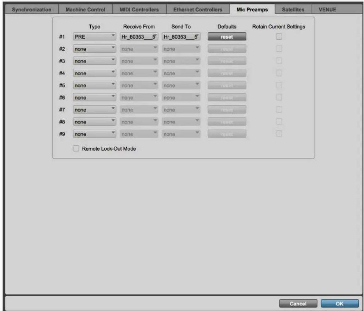
All details are available in the Virtual Audio Device (formerly Core Audio) Guide: http://www.merging.com/products/networked-audio/downloads
Pro Tools on PC Horus/Hapi
Analog preamps can be controlled directly from within Avid Pro Tools running on a PC. In order to set Pro Tools up for Horus/Hapi preamp control follow this procedure:
- Check the Horus/Hapi firmware version and update if necessary, to v19734 or above.
- Connect Horus/Hapi to the system running Pro Tools through the Ethernet. port.
- Download rptMIDI from here: http://www.tobias-erichsen.de/wp-content/uploads/2020/01/rtpMIDISetup_1_1_14_247.zip Install rptMIDI
- Start rptMIDI

rptMIDI control panel
- In the My Sessions section (top left) click on the + button to add a new entry.
- In the Session section (right) rename the entry in the Local name: field to HorusPre/HapiPre.
- In the Directory section (bottom left) select the Horus_80xxx_midi_pre module entry to add it to the Participants list.
- At the top of the Session section check the Enabled box to enable the session.
- Close the rptMIDI control panel.
- Open the MTDiscovery or ANEMAN application and check that the Horus is connected.
- Please see: Within Pro Tools on page 38 and follow step 10 and complete the subsequent steps in Pro Tools followed by restarting Pro Tools
Block Diagram
![graph TD A["HD Native"] --> B["Computer (Mac OS)"] B --> C["HTunderbolt Port"] B --> D["Pro Tools"] B --> E["Hapi"] E --> F["AOS"] E --> G["PSDF"] E --> H["WCK In"] E --> I["RJ45"] E --> J["WCK Out"] E --> K["AE"] E --> L["DIA1"] E --> M["A/D1"] E --> N["DIA2"] E --> O["A/D2"] E --> P["DIA3"] E -->…](/content/2026/05/903531/images/9b4378636b5a3939474d44cea1c4912faf8b6cb87ed6432e419e2a38f641d4b6.jpg)
To be able to use Horus and Hapi MIDI din.
Prerequisite:
- Plug the Sync break out cable (CON-D15-VTC) at the back of your unit (SYNC connector)
On Windows :
Pyramix v12 > users:
Under the Pyramid Settings>Hardware>MIDI Sync page
In the Directory list, choose an Apple MIDI service suffixed by "...midi_din". This nomenclature correspond to the Physical MIDI DIN port of a Horus/Hapi product.

ASIO users :
- Make sure your Horus / HAPI is detected in MT Discovery or ANEMAN
- Download ans install RTPMidi http://www.tobias-erichsen.de/software/rtpmidi.html
- Start RTP MIDI
- In My Sessions section, click on the + sign to create a new session, and name it.
- Once the Session has been created, select the device_name_midi_din in the available streams and click on Connect.

- The midi_din stream will be passed in the Participants section, you can now use it in your favorite application.
RTPMIDI do not properly always refresh, if you need to change your settings in RTPMIDI, you will have to restart the computer for the changes to apply.
On MacOS:
Horus / Hapi MIDI DIN port can be used directly from within any DAW running on a Mac.
(RAVENNA Core Audio driver v2.0.28855 and above recommended).
In order to use a Horus / Hapi MIDI port in MacOS follow this procedure:
- Check the Horus / Hapi firmware version and update if necessary to the latest version. (v28855 or above)
- Connect Horus / Hapi to the system running the DAW through the Ethernet port. (v28855 or above)
- Make sure your Horus / HAPI is detected in MT Discovery or ANEMAN
- All available MIDI DIN port available on the network will appear as a usual MIDI port. i.e. Reaper
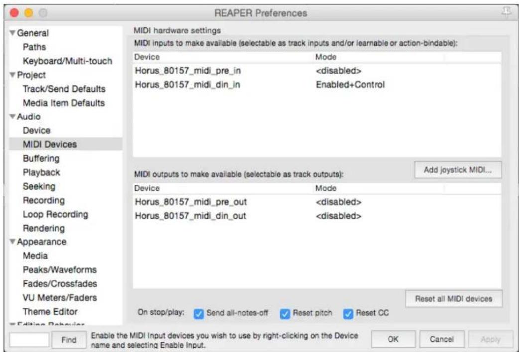
HAPI MKII - Firmware Update Procedure
PREREQUISITES
■ ANEMAN v1.3.0 and above. Download from https://www.merging.com/anubis/download
An internet connection to download the latest Hapi MKII Firmware https://www.merging.com/support/downloads#current-hapi-downloads
■ Connecting the ethernet interface of the Anubis to a Mac or PC system for the update procedure
■ Google Chrome is the recommended browser
⚠ Warning. Safari is known to cause update slowdown or update button might not appear. Use Chrome
UPDATE PROCEDURE
- Install ANEMAN or run MT Discovery (installed with some merging applications)
- Download the latest HAPI MKII Firmware from https://www.merging.com/support/downloads#current-hapi-downloads
- Connect your Hapi MKII network port to the system where you have downloaded the latest firmware
- Launching ANEMAN will discover your Hapi MKII within seconds.
- Once ANEMAN discovers Hapi MKII perform a Mouse + Right Click and select Web Services > Maintenance Page

If using MT Discovery perform a Mouse + Right Click on HapiMKII and select "Open Maintenance page"

Note: It is also feasible to access the Firmware Update from the Web Access > Setup page

- This will open a browser page from which you will be able to select the .hapimkii firmware file

- Use the "Select File" button to select your firmware
- This will open the explorer form where you can load the Hapi MKII Firmware

- Once the firmware is selected press the Update button

- Wait for the upload and update to complete.

Warning. Never abort the Firmware when it is updating, this could damage the HAPI configuration.

Notice that your Hapi MKII OLED will also display the progression of the update.


Warning: We do not recommend that you refresh the browser page or restart the Hapi while a firmware update is in progress.
- Once the Firmware update is completed please reboot your Hapi MKII. You can do this from either the browser or the Hapi MKII OLED, by selecting "Reboot Device"

You should now be on the latest Firmware. You can verify the Firmware version of your Hapi MK by opening the Info page under Setup>Settings>Info
![192kHz ■M Info Temperature: 56 [°C] Unit serial: H95041 ZMAN serial: 121450 Version: 1.2.1b46910](/content/2026/05/903531/images/3ed6fb3c3438743efc384a895bb3016931009afdeb67cc5ffb4e554ce423faf4.jpg)
In case you cannot access the Hapi MKII Maintenance mode.
Make sure that Hapi MKII is well connected to your system, it is mandatory that the Ethernet port or Switch is a Gigabit one.
Under the Setup>Settings>Info page take note of the written IP Address (ideally be set to Auto IP on both your Hapi MKII and Network Interface card).
Type the Hapi MKII address in your Chrome browser followed by :8080 Example: 169.254.250.11:8080 You could also just open the Hapi web access page and add the :8080 at the end of the IP address, follow by pressing enter.
You should now have access to the Hapi Maintenance page and be able to update your Hapi firmware
Start Up in Maintenance Mode (Rescue)
In case of problems updating the firmware or not being able to see the Hapi for update. You can start up the Hapi MkII in Maintenance Mode by pressing the power button and simultaneously pressing the Rotary encoder for a few seconds.
The Hapi MkII will then start in Maintenance Mode and will be ready for a firmware update.
HAPI - Troubleshooting
Hapi on screen Error Report
Your Hapi can display on the OLED screen some detected errors. In case of an error report the Hapi will display the message on its screen. Refer to the error list below as a reference. Once the issue is sorted Press the "clear" button to remove reported error. If the message reappears it indicates that the error is still present.
Hapi Error report example:
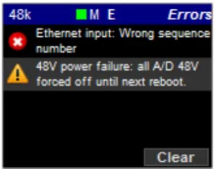
Potential reported errors:
"Primary Power Supply Failure";
"Secondary Power Supply Failure";
One of your Power supply is down, it is recommended that you eventually shutdown the Hapi and verify your power cord connections
"Hapi Application failure, please reboot"
The Hapi internal application has failed. Will require a reboot, make sure that you are using the latest Hapi firmware available. If the problem persists contact support@merging.com
"Ethernet input: GP fifo overrun";
"Ethernet input: GP descriptors fifo overrun";
The Ethernet communication is overloaded. The bandwidth is too small. Verify your set up, take note that a RAVENNA Network configuration must be running on a dedicated and certified Merging Switch. If problem persists contact our support team.
"Ethernet input: Audio packet still pending";
"Ethernet input: Audio pipeline too small";
"Ethernet input: Wrong sequence number";
"Ethernet input: CRC error";
"Ethernet input: Queue mux error";
"Ethernet input: Audio buffer too small";
"Ethernet input: SSRC mismatch"
Error on the incoming RAVENNA streams. There might be click on the physical output of the Hapi. Such a click could have occurred on one of the RAVENNA bank of 8 channels. Verify your set up, mainly on the network side and afterwards clear the error. If the problem persists contact our support team.
"Ethernet input: Unknown error";
"FPGA memory: Timeout";
"FPGA memory: Unknown error";
Contact Merging Support
"48V power failure: all A/D 48V forced off until next reboot"
The attached error message is displayed when:
- 48V is malfunctioning
- If there is a short circuit on 48V
If a MAJOR (by MAJOR, we mean that the threshold of short-circuit detection requires at least 10 Preamp inputs to be shorted simultaneously) 48V Phantom Power Supply short circuit is detected, 48V is forced off on all A/D channels and the following error message is displayed.
Note: 48V will be forced off until reboot.
Note: the user 48V settings are not affected i.e. the UI still shows the 48V as configured by the user.
How to provide Merging Support with a Hapi MKII Debug Report file
- Connect your Hapi MKII to your system via Ethernet
- Open MT Discovery or ANEMAN and Mouse+Right Click on the Hapi MKII entry to select Advanced Page
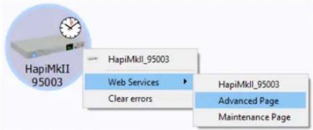
- This will open RAVENNA Advanced page in your web browser (e.g. Google Chrome)
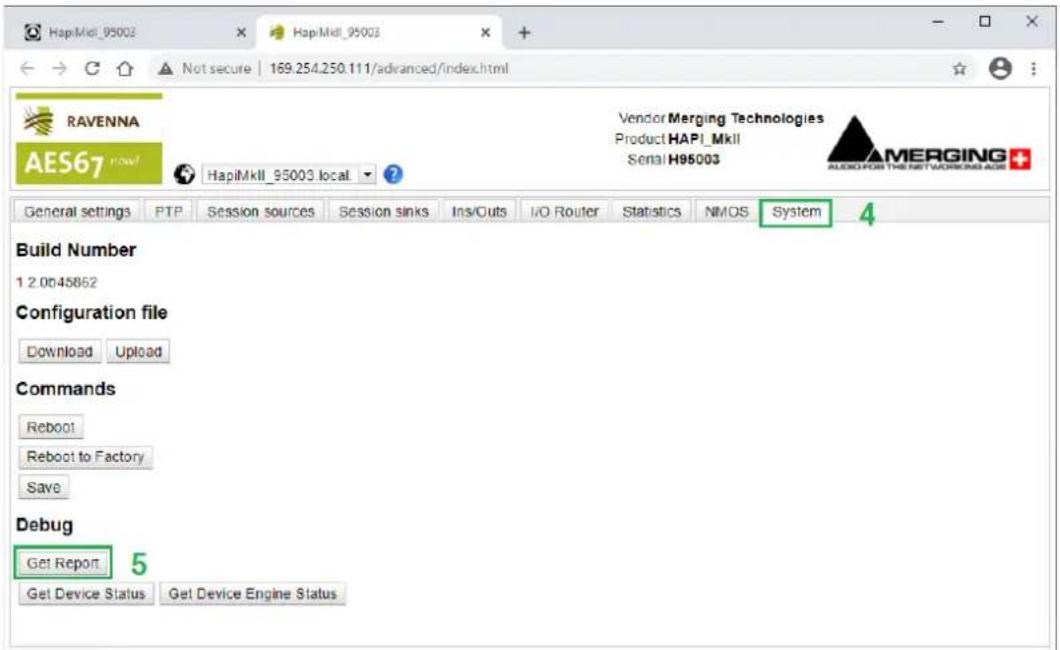
- Select the System Tab
- Click Get Report button and save HapiMkii_95xxx_report.bin file.
- Send to Merging the .bin file report.
Firewall and Antivirus
Windows Firewall:
The Windows Firewall can block communication between MassCore and Hapi.
By default, the built-in Windows Firewall should be automatically configured by the installer, but in some special cases, the user might have to configure it manually.
Antivirus: Merging also recommends users to configure their Antivirus, some Antivirus as Avast or
Sophos have been known to block the Hapi discovery and RAVENNA I/O Connections
Please see the details on
https://merging.atlassian.net/wiki/spaces/PUBLICDOC/pages/4820536/Antivirus+and+Merging+Technologies+Softwares
FOR MORE INFORMATION
MERGING+HAPI Website
https://www.merging.com/products/interfaces/hapi
MERGING+HAPI Downloads
https://www.merging.com/support/downloads#current-hapi-downloads
MERGING Knowledge Database, FAQs and Tutorials
https://merging.atlassian.net/wiki/spaces/PUBLICDOC/overview
MERGING SUPPORT
support@merging.com
MERGING YouTube CHANNEL
https://www.youtube.com/channel/UCR5q_dlb9dYnXTrVDWMshgw
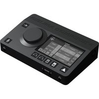

- HAPI MKII USER MANUAL
- CONTENTS
- IMPORTANT SAFETY AND INSTALLATION INSTRUCTION SAVE THESE INSTRUCTIONS
- INSTRUCTIONS PERTAINING TO RISK OF FIRE, ELECTRIC SHOCK, OR INJURY TO PERSONS
- IMPORTANT NOTICE
- STATIC DANGER NOTICE
- PRODUCT REGULATORY COMPLIANCE
- PRODUCT SAFETY COMPLIANCE
- PRODUCT EMC COMPLIANCE
- ELECTROMAGNETIC COMPATIBILITY NOTICES
- ENVIRONMENTAL LIMITS
- SYSTEM OFFICE ENVIRONMENT PARAMETER LIMITS
- EU DECLARATION OF CONFORMITY (DOC)
- APPLIED DIRECTIVES AND STANDARDS
- CONTACTING MERGING TECHNOLOGIES
- INTRODUCTION TO HAPI MKII
- MODULAR BY DESIGN
- ROUTE SIGNAL ANYWHERE
- GREEN BUILT
- HAPI MKII KEY FEATURES
- RAVENNA
- HAPI MKII - BLOCK DIAGRAM
- HAPI MKII - HARDWARE
- HAPI SCHEMATIC IMAGES
- HAPI BASE UNIT
- IOC-HAPI SPECIFICATIONS
- HEADPHONE MONITOR JACKS
- RAVENNA MODULE
- AES-EBU MODULE
- MADI MODULE
- ADAT/SPDIF MODULE
- SOFTWARE SPECIFICATIONS
- HAPI - OPTIONAL CARDS
- IOM-H-AKDG8D / AKDG8DP
- IOM-H-AKDG8D / AKDG8DP KEY FEATURES
- IOM-H-AKDG8D / AKD8GDP MIC PRE-AMP + ADC
- IOM-H-AKDG8D/ADDG8DP LINE INPUT SECTION
- IOM-H-AKDG8D / AKDG8DP DIRECT OUT SECTION
- IOM-H-AKDG8D / AKDG8DP DUAL PREAMP BLOCK DIAGRAM
- IOM-H-AKDG8D/AKDG8DP BLOCK DIAGRAM
- IOM-H-AKD8D / AKD8DP
- IOM-H-AKD8D / AKD8DP KEY FEATURES
- IOM-H-AKD8D / AKD8DP MIC PRE-AMP + ADC
- LINE INPUT
- IOM-H-AKD8D / AKD8DP MIC-PRE ANALOG SECTION
- IOM-H-AKD8D / AKD8DP DIRECT OUT SECTION
- GAIN BEHAVIOR OF THE DIRECT OUT SECTION
- IOM-H-AKD8D/AKD8DP BLOCK DIAGRAM
- IOM-H-AD8D / AD8DP - LEGACY PRODUCT
- IOM-H-AD8D / AD8DP KEY FEATURES
- IOM-H-AD8D / AD8DP MIC PRE-AMP + ADC
- IOM-H-AD8D/AD8DP MIC-PRE ANALOG SECTION
- IOM-H-AD8D/AD8DP DIRECT OUT SECTION
- IOM-H-AD8D/AD8DP BLOCK DIAGRAM
- IOM-H-DA8/DA8P (>= RUN 11)
- IOM-H-DA8/DA8P SPECIFICATIONS
- LINE OUTPUT LEVEL CALIBRATION
- HOW TO CONNECT THE SYMMETRICAL LINE OUT TO AN UNBALANCED INPUT
- IOM-HORUS-DA8/DA8P (< RUN 11) - LEGACY PRODUCT
- IOM-HORUS-DA8/DA8P KEY FEATURES
- IOM-HORUS-DA8/DA8P SPECIFICATIONS
- PROCEDURE FOR HARDWARE ALIGNMENT (FOR DA8 PRIOR TO RUN 7)
- OUTPUT LEVEL CALIBRATION EXAMPLE
- IOM-H-ADA8S/ADA8P
- IOM-H-ADA8S/ADA8P KEY FEATURES
- IOM-H-ADA8S/ADA8P SPECIFICATIONS
- IOM-H-ADA8S/ADA8P MIC-PRE + ADC SECTION
- IOM-H-ADA8S/ADA8P LINE INPUT SECTION
- IOM-H-ADA8S/ADA8P LINE OUT SECTION
- IOM-H-ADA8S/ADA8P DUAL PREAMP BLOCK DIAGRAM
- ADA8S AND ADA8P ROLL OFF FILTERS
- IOM-H-ADA8 - LEGACY PRODUCT
- IOM-H-ADA8 KEY FEATURES
- IOM-H-ADA8 SPECIFICATIONS
- IOM-H-ADA8 MIC-PRE + ADC SECTION
- IOM-H-ADA8 LINE INPUT SECTION
- IOM-H-ADA8 MIC-PRE ANALOG SECTION
- IOM-H-ADA8 LINE OUT SECTION
- IOM-H-ADA8 BLOCK DIAGRAM
- IOM-H-PT64
- IOM-H-PT64 KEY FEATURES
- PORTS USAGE
- SYNCHRONIZATION AND WORD CLOCK
- SAMPLING RATE MISMATCH PROTECTION
- SETUPS WITH MULTIPLE DEVICES
- DELAY COMPENSATION
- EMULATION MODE
- ERROR AAE -6116
- IOM-HAPI-MADM/MADS
- IOM-HAPI-MADM/MADS FEATURES
- HAPI - CABLES
- CONNECTING THE ANALOG AUDIO INPUT CABLES TO THE AD8/AD8P/AKD8D/AKD8DP/ADA8S/ADA8P MODULES
- SPECIFICATIONS
- CONNECTING THE ANALOGUE OUTPUTS CABLES TO THE DA8/DA8P MODULES
- CONNECTING THE AES-EBU CABLE
- CONNECTING THE MADI CABLE
- CONNECTING THE WORDCLOCK INPUT/OUTPUT
- CONNECTING THE SYNC CABLE
- CONNECTING THE RAVENNA ETHERNET CABLES
- NETWORKING
- MODULAR ANALOG INTERFACING
- MODULAR DEVICE CONNECTIVITY
- AD8 / AD8P REMOTE CONTROLLED MIC/LINE A/D MODULE
- DA8 / DA8P SAFETY CONSCIOUS ANALOGUE LINE OUTPUT MODULES
- ADA8 REMOTE CONTROLLED MIC/LINE A/D MODULE WITH TRANSPARENT ANALOG OUTPUT
- HD LINK WITH PRO TOOLS HD
- DC POWER SUPPLY OPTIONS
- MADI (MODULE)
- AES-EBU
- ADAT/SPDIF
- PT64
- SIGNAL ROUTING PARADIGM
- RAVENNA IP AUDIO
- SYNCHRONIZATION
- KEY SPECIFICATIONS
- INSTALLING AN ADDITIONAL HAPI I/O MODULE
- BEFORE YOU START
- HARDWARE INSTALLATION
- PLEASE ENSURE THAT YOUR HAPI UNIT IS SWITCHED OFF BEFORE ATTEMPTING TO CONNECT ANY CABLES TO THE UNIT
- INSTALLING A HAPI MADI MODULE (MADM OR MADS ARE OPTIONAL)
- BEFORE YOU GET STARTED
- INSTALLING HAPI MADI I/O MODULE PROCEDURE
- ASSEMBLING THE RACK MOUNT EARS
- INSTALLING THE RACK MOUNT EARS ON THE FRONT PANEL
- INSTALLING THE RACK MOUNT EARS ON THE REAR PANEL
- HAPI RECOMMENDED PLACEMENT IN RACK
- INSTALLING THE MERGING NET-MSC-GBEX1
- HAPI MK II - POWER ON
- CONNECTING THE POWER CABLE
- HAPI DC POWER INPUT
- HAPI POWER UP MODE SELECTION
- TURN ON YOUR HAPI
- POWER BUTTON COLOR CODE
- HAPI MKII - OLED SCREEN INTERFACE
- SCREEN NAVIGATION
- THE ROTARY CONTROL
- PUSH
- HOME SCREEN
- VOLUME MENU
- METERS MENU
- A/D METERS SUB-MENU (METERS)
- D/A METERS SUB-MENU (METERS)
- INPUT LEVELS SUB-MENU (METERS)
- OUTPUT LEVELS SUB-MENU (METERS)
- METERS SETTINGS MENU
- I/O MENU & SYNC SUB-MENU (I/O)
- REFS SUB-MENU (I/O)
- TIMECODE SUB-MENU (I/O)
- STATUS SUB-MENU (I/O)
- PREAMP MENU
- SETUP MENU
- FORMATS MENU (SETUP)
- ROUTING MENU (SETUP)
- ROUTING: SOURCE CONFIGURATION
- ROUTING EXAMPLE
- MODULES MENU (SETUP)
- AES
- HEADPHONE
- D/A N
- TRIM : HEADPHONE / DA N / ADA N
- A/D N / AKD N
- ADA N
- PT N
- MADI
- TIMECODE
- HEADPHONE MENU
- MODULES: MADI SUB-MENU
- MODULES: A/D SUB-MENU
- MODULES: ADA SUB-MENU
- MODULES: D/A SUB-MENU
- TRIM: DA
- MODULES: PT64 SUB-MENU
- PRESETS MENU (SETUP)
- SYSTEM (SETUP)
- NETWORK MENU (SETUP)
- INFO (SETUP)
- ERROR MENU
- EXIT MENU
- HAPI MKII - WEB CONTROL ACCESS
- INSTALLING AND ACCESSING THE HAPI CONTROL INTERFACE REMOTELY
- HAPI MKII WEB ACCESS
- HOME PAGE WEB ACCESS
- HOME PAGE LAYOUT ENTRIES
- METERS
- METERS WEB SETTINGS
- IO & SYNC WEB ACCESS
- PREAMP WEB ACCESS
- SETUP WEB ACCESS
- FORMAT
- ROUTING
- MODULES
- PRESET WEB ACCESS
- SETTINGS
- PASSWORDS AND FORMS
- WEB CONTENT
- NETWORK
- LANGUAGES
- DOWNLOADS
- NETWORK WEB ACCESS
- SYSTEM WEB ACCESS
- INFO WEB ACCESS
- EXIT WEB ACCESS
- IDENTIFY ME – DEVICE LOCATION
- PROCEDURE
- HAPI MKII EMBEDDED USER MANUAL
- DISCONNECTION WARNING - WEB ACCESS
- HAPI & HORUS SETUP EXAMPLES
- STAGE EQUIPMENT
- MIX/RECORDING ROOM
- BACKUP RECORDING/EDITING RIG
- BROADCAST ROOM
- DESCRIPTION
- RAVENNA NETWORK FOR MULTIPLE MASTERING SUITES WITH A SHARED MACHINE ROOM
- SHARED EQUIPMENT
- STUDIO EQUIPMENT
- RAVENNA NETWORK FOR MULTIPLE STUDIOS WITH A SHARED LIVE ROOM
- LIVE ROOM EQUIPMENT
- IOM-H-PT64 & DIGIDESIGN HDIO SETUP
- HARDWARE SETUP
- IN HAPI
- IN PRO TOOLS
- MANAGE MIC PRES FROM PRO TOOLS
- PRO TOOLS ON PC HORUS/HAPI
- PREREQUISITE
- ON WINDOWS
- ASIO USERS
- ON MACOS
- HAPI MKII - FIRMWARE UPDATE PROCEDURE
- PREREQUISITES
- UPDATE PROCEDURE
- IN CASE YOU CANNOT ACCESS THE HAPI MKII MAINTENANCE MODE
- START UP IN MAINTENANCE MODE (RESCUE)
- HAPI - TROUBLESHOOTING
- HAPI ON SCREEN ERROR REPORT
- HOW TO PROVIDE MERGING SUPPORT WITH A HAPI MKII DEBUG REPORT FILE
- FIREWALL AND ANTIVIRUS
- FOR MORE INFORMATION
Brand : Merging
Model : Hapi MKII
Category : Audio recorder