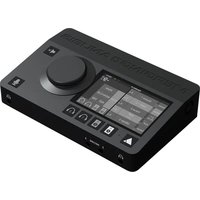
Anubis Pro SPS - Audio Interface Merging - Free user manual and instructions
Find the device manual for free Anubis Pro SPS Merging in PDF.


| Type of Product | Networked Audio Monitor Controller / Audio Interface |
| Dimensions (H x W x D) | 44 x 220 x 200 mm (1/2 rack width, 1U height) |
| Weight | 2.5 kg |
| Power Supply | 12V DC 2A (center positive) or PoE+ (802.3at) |
| Main Functions | Dante audio networking, monitor control with talkback, headphone outputs, and analog inputs |
| Supported Sample Rates | 44.1 kHz to 384 kHz |
| Analog Inputs | 2 x XLR/TRS combo, microphone preamps, line inputs |
| Analog Outputs | 2 x XLR balanced (main), 2 x TRS (line), 1 x stereo headphone |
| Digital I/O | Dante primary and secondary ports, AES3 I/O |
| Network Interface | 2 x Gigabit Ethernet, Dante redundant |
| Remote Control | Via Web UI, Merging Unity software, or optional hardware remote |
| Maintenance and Cleaning | Use a soft dry cloth; avoid solvents and liquids |
| Safety Precautions | Operate within 0-40°C; use supplied power adapter only |
| Spare Parts and Repairability | Contact Merging support; authorized service only |
| General Information | Professional-grade device; firmware upgradable via network |
Frequently Asked Questions - Anubis Pro SPS Merging
User questions about Anubis Pro SPS Merging
0 question about this device. Answer the ones you know or ask your own.
Ask a new question about this device
Download the instructions for your Audio Interface in PDF format for free! Find your manual Anubis Pro SPS - Merging and take your electronic device back in hand. On this page are published all the documents necessary for the use of your device. Anubis Pro SPS by Merging.
USER MANUAL Anubis Pro SPS Merging
Thank you for purchasing MERGING+ANUBIS....5
Important Safety and Installation Instructions....6
Product Regulatory Compliance 8
MERGING+ANUBIS Warranty Information 11
INTRODUCTION....11
Package Content 12
OVERVIEW....13
MERGING+ANUBIS VARIANTS AND KEY FEATURES....13
ABOUT RAVENNA 16
MISSION CONTROL - MODULAR BY SOFTWARE....16
MERGING+ANUBIS panels description....17
TOP PANEL 17
BACK PANEL....19
FRONT PANEL 21
ANUBIS ANALOGUE I/O BLOCK DIAGRAM....22
HOW TO CONNECT MERGING+ANUBIS 23
Connecting the Ethernet cable to the Network for RAVENNA use 23
How to connect a balanced line output to an unbalanced input 24
DRIVERS INSTALLATION PROCEDURE 25
Windows PC - RAVENNA ASIO Driver or Merging Audio Device (MAD) 25
Mac OS - VAD Premium 26
POWER SUPPLY 28
Using the DC power supply source 28
Using the Power-over-Ethernet (PoE) source 28
Switching ON MERGING+ANUBIS 29
Legacy Home Page (Firmware 1.4.8 and prior) New Home Page, Firmware 1.4.10 and above .... 29
TOUCHSCREEN AND NAVIGATION....30
ANUBIS HOME PAGE 31
Legacy Home Page (Firmware 1.4.8 and prior) New Home Page Firmware 1.4.10 and above ..... 31
STATUS BAR 32
LOGS MESSAGES....33
LOG MESSAGE APPENDIX....34
PREAMPS CONTROL....35
DUAL GAIN 32bit CIRCUITRY 40
SPLIT CHANNEL 41
Analog levels and Digital levels (after A/D conversion) 41
ANUBIS VIRTUAL KEYBOARD 42
SETTINGS 44
SETTINGS CATEGORIES DESCRIPTION....45
PRESETS Settings....50
MONITORING Settings....51
Stream Listener Source 55
ANUBIS EQ GUIDELINES....62
SUB SETTINGS (BASS MANAGEMENT) 69
Bass Management Signal flow....71
ROOM CORRECTION with SONARWORKS SoundID REFERENCE 72
Note: Select and load a SoundID profile from the Dropdown listing. Profiles can also be applied from the Settings>Monitors....78
Sound ID integration latency when enabled (as of Firmware 1.4.6 and above) 78
Remote SoundID Controls 79
ACCESS CONTROL Settings 94
INFO Settings 96
DEBUG Settings....96
EXIT Settings....97
ANUBIS MONITOR MISSION CONTROL 98
Missions IO Channels Specifications....101
Sources vs. Monitors Fundamentals 102
Different Monitor types 103
MAIN PAGES - MONITOR MISSION....104
MONITOR PAGE 105
Downmix Table....110
SOURCE PAGE 111
METERS PAGE....114
ANUBIS PREMIUM DXD-DSD GUIDELINES....116
DSD Features & Restrictions: 116
DSD MONITORING: 117
ANUBIS PREMIUM GENERAL SETTINGS....119
DSD PreAmps 120
ANUBIS SPS 123
PEERING 129
How to peer a device....131
Peering Rules & Behavior....135
ANUBIS USE CASES (MULTIPLE CASES ARE ONLINE)....135
BASIC MONITORING SETUP....136
RECORDING SETUP....140
MORE ANUBIS USE CASES HERE....145
MONITORING WEB USER INTERFACE 146
How to Open the Remote Web User Interface 147
Web Access Source and Monitor Renaming 150
Web Access PreAmps Remote Control 151
Web Access Settings 153
Tablets Remote Access - Using the Anubis IP Address 154
ANUBIS FIRMWARE UPDATE PROCEDURE 156
ANUBIS TECHNICAL SPECIFICATIONS 159
APPENDICES 163
FOR MORE INFORMATION 171
Thank you for purchasing MERGING+ANUBIS
This manual is intended to take you through the setup and installation of the MERGING+ANUBIS. We encourage you to familiarize yourself with the features, applications, and connection procedures before setting up your MERGING+ANUBIS.
To ensure the safe operation of your Anubis, please read the instructions, important safety information, and warnings carefully before installation and use.
Important Safety and Installation Instructions
INSTRUCTIONS PERTAINING TO RISK OF FIRE, ELECTRIC SHOCK, OR INJURY TO PERSONS
WARNING – when using electrical products, basic precautions should be followed, including the following:
- Before using this product, read all of the safety and installation instructions and the explanation of graphic symbols.
- This product must be grounded otherwise it could malfunction or breakdown. Grounding provides a path of least resistance for electric current to reduce the risk of electric shock. If using the AC adapter of this product, make sure to use the power supply cable having an equipment-grounding conductor and a grounding plug. The mains cable should be plugged into an appropriate outlet, which is properly installed and grounded in accordance with all local codes and ordinances. DANGER – Improper connection of the equipment grounding can result in a risk of electric shock. Do not modify the plug provided with the product – if it will not fit the outlet, have a proper outlet installed by a qualified electrician. Do not use an adapter that defeats the function of the equipment-grounding conductor. If you are in doubt as to whether the product is properly grounded, check with a qualified serviceman or electrician.
- Do not use this product near water or in a damp environment, for example, near a bathtub, washbowl, kitchen sink, in a wet basement, or near a swimming pool, or the like.
- This product, either alone or in combination with an amplifier and speakers or headphones, may be capable of producing sound levels that could cause permanent hearing loss. Do not operate at a high volume level or at a level that is uncomfortable. If you experience any hearing loss or ringing in the ears, you should consult an audiologist.
- The product should be located so that its location or position does not interfere with its proper ventilation.
- The product should be located away from heat sources such as radiators or other products that produce heat.
- The product should be connected to a power supply only of the type described in the operating instructions or as marked on the product.
- The product's power-supply cable should be unplugged from the outlet when it is to be left unused for a long period of time. When unplugging the power supply cable, grasp it by the plug. Do not pull on the cable itself.
- Care should be taken so that objects do not fall on to the product and liquids are not spilled onto any part of the enclosure.
- The product should be serviced by qualified service personnel when: a. The power supply cable or plug has been damaged. b. Objects have fallen onto the product, or liquid has spilled and may have leaked into the product. c. The product has been exposed to rain. d. The product does not appear to be operating normally or exhibits a marked change in performance. e. The product has been dropped, or the enclosure damaged.
- Do not attempt to service the product beyond that described in the user maintenance instructions. All other servicing should be referred to qualified service personnel.
- WARNING - Do not place any objects on the power supply cable, or place the product in a position where anyone could trip over, walk on, or roll anything over the cable. Do not allow the product to rest on or be installed over cables of any type. Improper installations of this type create the possibility of a fire hazard and/or personal injury.

The lightning flash with arrowhead symbol, within an equilateral triangle, is intended to alert the user to the presence of uninsulated "dangerous voltage" within the product's enclosure that may
be of sufficient magnitude to constitute a risk of electric shock to persons.

The exclamation point within an equilateral triangle is intended to alert the user to the presence of important operating and maintenance (servicing) instructions in the literature accompanying the product.
IMPORTANT NOTICE:
Please read the following information very carefully before attempting any installation. Failure to comply with the precise instructions may result in damage to your Merging hardware. Please read this entire section of the manual carefully before installation.
STATIC ELECTRICITY DANGER NOTICE:
Please note that the MERGING+ANUBIS contains delicate electronic components that can be damaged or even destroyed when exposed to static electricity. Take all necessary precautions not to discharge static electricity into the equipment when touching any of the MERGING+ANUBIS connectors.
Merging Technologies makes no warranties express or implied regarding the MERGING+ANUBIS embedded software, its quality, performance, merchantability or fitness for a particular purpose. The software is supplied "as is" and you, the purchaser, are assuming the entire risk of the results of using this Merging Technologies software.
In no circumstances will Merging Technologies, its owners, directors, officers, employees or agents be liable to you for any consequential, incidental or indirect loss or damages including loss of time, loss of business, loss of profits, loss of data or similar resulting from the use of or inability to use the Merging Technologies hardware and or software or for any defect in the hardware software or documentation.
© Copyright Merging Technologies Inc. 2023. All rights reserved.
Product Regulatory Compliance
Product Safety and EMC Compliance
Merging Technologies ANUBIS is designed, tested and verified to comply with the following Safety & EMC regulations FCC – Radiated and Conducted Emissions (USA).
CFR 47 Part 15 – Radiated and Conducted Emissions (Canada).
CISPR 22:2008 (class B) – Radiated and Conducted Emissions (International).
CISPR 32:2012 (class B) – Radiated and Conducted Emissions (International).
CISPR 24:2010 - Immunity (International).
EN 55022:2010 (class B) – Radiated and Conducted Emissions (European Union).
EN 55032:2012 (class B) – Radiated and Conducted Emissions (European Union).
EN 55024:2010 – Immunity (European Union).
EN61000-3-2 & -3 – (Power Harmonics and Fluctuation and Flicker).
Electromagnetic Compatibility Notices
This device complies with Part 15 of the FCC Rules. Operation is subject to the following two conditions: (1) this device may not cause harmful interference and (2), this device must accept any interference received, including interference that may cause undesired operation.
This equipment has been tested and found to comply with the limits for a Class B digital device, pursuant to Part 15 of the FCC Rules. These limits are designed to provide reasonable protection against harmful interference in a residential installation. This equipment generates, uses, and can radiate radio frequency energy and, if not installed and used in accordance with the instructions, may cause harmful interference to radio communications. However, there is no guarantee that interference will not occur in a particular installation. If this equipment does cause harmful interference to radio or television reception, which can be determined by turning the equipment off and on, the user is encouraged to try to correct the interference by one or more of the following measures:
Reorient or relocate the receiving antenna.
Increase the separation between the equipment and the receiver.
Connect the equipment to an outlet on a circuit other than the one to which the receiver is connected.
Consult the dealer or an experienced radio/TV technician for help.
Any changes or modifications not expressly approved by the grantee of this device could void the user's authority to operate the equipment. The customer is responsible for ensuring compliance of the modified product.
Only peripherals (computer input/output devices, Ethernet switches, terminals, printers, etc.) that comply with FCC Class B limits may be attached to this computer product. Operation with noncompliant peripherals is likely to result in interference to radio and TV reception.
All cables used to connect to peripherals must be shielded and grounded. Operation with cables, connected to peripherals that are not shielded and grounded, may result in interference to radio and TV reception.
Environmental Limits
System Office Environment Parameter Limits
Operating Temperature +5 degrees C to +45 degrees C with the maximum rate of change not to exceed 10 degrees C per hour.
Non-Operating Temperature -40 degrees C to +70 degrees C
Non-Operating Humidity 95%, non-condensing @ 30 degrees C
Operating Shock No errors with a half sine wave shock of 2G (with 11-millisecond duration).
Package Shock Operational after a free fall, 60 cm depending on the weight.
ESD 8kV per Merging Technologies Environmental Test Specification
EU Declaration of Conformity (DoC)
Merging Technologies S.A.
Le Verney 4
CH-1070 Puidoux
Switzerland
declares that the DoC is issued under its sole responsibility that the product:
Model: Anubis
Type: IOC-ANU-PRO, IOC-ANU-PRE, IOC-ANU-PRO-SP, IOC-ANU-PRE-SP
with the included component:
Power supply: ATS024T-P120
and all variations specified in the annex are in conformity with the provisions of the following EU directive(s) (including all applicable amendments); and are designed and manufactured with application of the harmonized standards.
The history of this document is listed on the last page.

Puidoux, May 15, 2020
Claude Cellier, CEO
Applied directives and standards:
| The devices: IOC-ANU-PRO, IOC-ANU-PRE, IOC-ANU-PRO-SP, IOC-ANU-PRE-SP comply with the following: | |||
| Pos.-No. | Document | Short description | Issued / Version |
| 3010 | 2014/35/EU | Low Voltage Directive 2014/35/EUElectrical Safety (publication references OJEU L 96, 29.03.2014, p.357-374) | 2014-02 |
| 3301 | EN 62368-1 | Audio/video, information and communication technology equipment - Part 1: Safety requirements | 2014 + AC:2015 + A11:2017 |
| 7551 | No. 2019/1782 | EU-Regulation for External Power Supplies (Energy Efficiency) (publication references OJEU L 272, 25.10.2019, p. 95-106) | 2020-04 |
| 7801 | 2011/65/EU | RoHS Directive 2011/65/EURestriction of the use of certain hazardous substance (publication references OJ L 174, 01.07.2011, p.88-110) amended by (EU) 2015/863) | 2011-06 with all amendments |
| 7820 | EN IEC 63000 | Technical documentation for the assessment of electrical and electronic products with respect to the restriction of hazardous substances | 2018-12 |
Document History
| Revision Date: | Revision Description | Remarks |
| 2020-05-15 | First version | |
MERGING+ANUBIS Warranty Information
This product is warranted to be free of defects in materials and workmanship for a period of two years from the date of purchase. Merging Technologies, Inc. extends this Limited Warranty to the original purchaser.
In the event of a defect or failure to conform to this Limited Warranty, Merging Technologies, Inc. will repair or replace the product without charge within sixty (60) days. In order to make a claim under this limited warranty, the purchaser must notify Merging Technologies, Inc. or their representative in writing, of the product failure. In this limited warranty the customer must, upon Merging Technologies, Inc. request, return the product to the place of purchase, or other local designation, for the necessary repairs to be performed. If the consumer is not satisfied with the repair, Merging Technologies, Inc. will have the option to either attempt a further repair, or refund the purchase price.
This warranty does not cover: (1) Products which have been subject to misuse, abuse, accident, physical damage, neglect, exposure to fire, water or excessive changes in the climate or temperature, or operation outside maximum rating. (2) Products on which warranty stickers or product serial numbers have been removed, altered or rendered illegible. (3) The cost of installations, removal or reinstallation. (4) Damages caused to any other products. (5) Do not attempt to service the equipment. There are no user serviceable parts inside*. Please refer all servicing to an authorized Merging Technologies sales partner. Any attempt to service the equipment will expose you to a risk of electric shock, and will void the manufacturer's warranty.
Replacing or adding hardware components is permitted under the supervision of a Merging Technologies sales partner. Any other modification will void the MERGING+ANUBIS warranty.
Contacting Merging Technologies
International Office:
Merging Technologies S.A.
Le Verney 4
CH-1070 Puidoux
Switzerland
Phone: +41 21 946 0444
Email: support@merging.com
For all documentation inquiries or suggestions for improvement: www.merging.com
Product features and specifications are subject to change without notice.
Merging Technologies SA shall not be liable for technical or editorial errors contained herein, nor for incidental or consequential damages resulting from the furnishing, performance or use of this manual.
© 2023 All rights reserved. Merging Technologies and MERGING+ANUBIS are registered Trademarks of Merging Technologies SA.
INTRODUCTION
Thank you for choosing Merging Technologies. The MERGING+ANUBIS has a wide range of advanced features. Before attempting to use your new MERGING+ANUBIS product, we strongly recommend that you read this manual, as it will enable you to obtain the best experience and performance from it.
Environmentally Friendly by Design
The MERGING+ANUBIS products have been carefully designed in order to keep power consumption to a strict minimum. Merging Technologies believes in a sustainable future and takes appropriate measures at all phases of a product's design and manufacture to avoid wasting energy. This said, we will never compromise on sound quality and electronic components are carefully selected based on their audio performance first and foremost. The side benefit is that if equipment runs cool it is usually also a guarantee of longevity and long-term reliability.
Package Content
If the shipping carton shows any signs of damage, please inform your Merging Technologies dealer or purchased store, as the product may also have sustained damage. Please retain all the packing, and particularly the soft-shell case, as this must be used should you need to ship the unit in the future. The use of any other packing may result in the unit sustaining damage in transit, which will not be covered by the warranty.
In addition to the Safety information and quick start guide, the carton should contain the items shown below. If any of these is missing please contact your Merging Technologies dealer.
Figure 1. Items inside the box.
Soft-shell case

MERGING+ANUBIS

Quick Start Guide

Ethernet RJ45 cable

Power Supply (12V)
Power Cable*
Note: Additional items could be added to your Anubis package depending of your purchased order. *Power cable varies with purchased country (US, EU, CH).
OVERVIEW
MERGING+ANUBIS is a ground-breaking new audio interface incorporating the Swiss expertise of Merging Technologies in analogue and digital, networked audio and DSP technology. More significantly, it offers unique features to any engineer or musician looking for a compact AD/DA unit with the quality you would expect from Merging, and a fully featured monitor controller that integrates with any DAW.
MERGING+ANUBIS was designed in Switzerland, where it is assembled and tested to the same exacting standards as our complete line of professional products and is intended to deliver the same high level of performance and reliability.
MERGING+ANUBIS VARIANTS AND KEY FEATURES
VARIANTS
MERGING+ANUBIS PRO: Supports sample rates from 44.1kHz to 192kHz PCM at a 32-bit resolution
MERGING+ANUBIS PREMIUM: Supports sample rates from 44.1kHz to 352.8kHz (DXD) and 384kHz PCM at a 32-bit resolution plus high resolution DSD64, DSD128 and DSD256 formats.
MERGING+ANUBIS SPS PRO: Seamless Protection Switching. ST2022-7 class C and NMOS compliance and built-in switch mode. Supports sample rates from 44.1kHz to 192kHz PCM at a 32-bit resolution
MERGING+ANUBIS SPS PREMIUM: Seamless Protection Switching. ST2022-7 class C and NMOS compliance and built-in switch mode.
Supports sample rates from 44.1kHz to 352.8kHz (DXD) and 384kHz PCM at a 32-bit resolution plus high resolution DSD64, DSD128 and DSD256 formats.
KEY FEATURES
- Modular by software. Evolving long life product with multiple missions (upcoming) ■ Merging class of its own sound quality
- Ethernet with RAVENNA interface allows asynchronous data transfer with computer audio systems and allows cable runs up to 100m with Cat5e/Cat6 cable
- Standalone or central part of a highly scalable and expandable network. Multiple MERGING+ANUBIS or RAVENNA/AES67 compliant interfaces can be connected to the network and Anubis can remotely and locally: Control, Mix, Monitor multichannel content and route those I/O's. ■ Full 32 bit signal path from analog Input to Output, via Mixer ■ TFT LCD capacitive multi-touch screen ■ Web based remote control accessible via smartphone, tablet or computer.
- Rotary Control knob allowing easy adjustment of volume level. The rotary knob provides also access to comprehensive and intuitive menu within the Anubis software ■ FPGA-based DSP mixer with effects with ultra-low latency for the performer foldback/Cues
■ Up to 4 x 128 x 8 Mix engines ■ Redundant power supply with PoE and DC Power Supply - SMPTE 2110-30 support: Audio transport is built on AES67 uncompressed 48kHz PCM audio. Up to 8 channels can be bundled in one stream,16- and 24-bit depth are supported. ■ SMPTE 2110-10 support: PTP v2 (IEEE 1588) ■ ST2022-7 Support with new Anubis SPS (Seamless Protection Switching) and as of firmware 1.1.X and above. ■ NMOS Support as of firmware 1.1.X and above. Refer to the link below for more details. https://merging.atlassian.net/wiki/spaces/PUBLICDOC/pages/4819466/NMOS+Implementation+Notes
Microphone Preamplifiers
■ Unprecedented audio transparency with a Dynamic Range (A Weighted) of 139 dB Typical - 48V phantom power, Low cut filter, Pad and Boost, Phase inversion, Stereo Linking, Lock and Cut features ■ Dual Gain 32 bit AD circuitry ■ Huge Dynamic Range with ample headroom ■ Totally clickless Gain steps
- Split Channel feature
- Possibility to independently control FOH & Monitoring Microphone Gains without any conflict
- Possibility to cut input signals to FOH while monitoring it from other outputs (e.g. Headphones) for signal check by example.
- Possibility to record duplicate of the input channel at a different input gain level (for backup or peak-safety recording)
Instrument/Line inputs
■ Two Instrument/Line inputs on front panel. Can be used for Hi-Z instruments or Line inputs ■ Dynamic Range (A Weighted) of 136 dB Typical ■ Independent gain levels for Instrument or Line inputs ■ Dual Gain and Split channels feature as above
Monitoring
■ Two Individual stereo main balanced XLR outputs with mono, dim, mute, level control and mixing possibilities. Can be used for Main monitor set - Two Individual stereo main balanced TRS outputs with mono, dim, mute, level control and mixing possibilities. Can be used for auxiliary monitors of additional Cue Mix ■ Two independent headphones sockets with independent level control ■ Two exceptional high-power headphone amps with dedicated DACs ■ Mute switch for any outputs ■ Adjustable Max, Ref, Dim levels - Crossfeed for headphones. Recreate the stereo image heard from speakers by mixing some signal from the left channel into the right channel, and vice versa - Instant access dedicated soft buttons
Monitor Mission Specs
■ The remote allows control of volume level and source selection of any Merging RAVENNA Device on the network ■ In the Box and Expandable I/O through Hapi, Horus or any RAVENNA/AES67 devices - Up to 8 Monitors capable of up to 22.2 (maximum 32 channels) ■ Up to 128 Sources capable of up to 22.2 (maximum 128 channels -2 dedicated to Talkback) ■ Up to 256 channels Analogue, MADI, AES3, SPDIF, Pro Tools HD I/Os via RAVENNA/AES67 ■ In-the-box I/O pairing management with Merging devices ■ Any other RAVENNA/AES67 devices pairing using ANEMAN ■ Down-mix selector (from mono to 22.2) ■ Sources trim (exclusive and sum) selector - Bass management
And more:
■ Power-over-Ethernet supplied: IEEE 802.3at compliant ■ GPIO general-purpose input/output for studio (e.g. Record light control) or live (e.g. Foot switch) ■ MIDI input and output for conventional digital sources ■ Connects from/to the computer using standard ASIO on Windows, Core Audio on Mac or ALSA on Linux ■ Mic stand mount ■ Kensington security slot ■ Built-in talkback microphone for communication and recording, possibility for 2 independent Talkbacks ■ 18 Save/Recall Internal Presets and unlimited external Presets Save/Recall. ■ Mic/Pre DAW remote control ■ Standalone operations. Anubis can serve as a multi-channel analog converter or headphone amp when disconnected from the computer. ■ Built-in Room Correction support for SoundID (Sonarworks) ■ Access control: Protect settings and other parameters with a password
ABOUT RAVENNA
RAVENNA is a solution for real-time distribution of audio and other media content in IP-based network environments. Utilizing standardized network protocols and technologies, RAVENNA can operate in existing network infrastructures and is fully AES67 compliant. The RAVENNA protocol manages the data transfer between the MERGING+ANUBIS and a computer or other hardware when the Ethernet interface is used. This open and published IP network technology had been created to meet the demands of national broadcasters and focused on the essential requirements of extremely accurate clocking, high resistance to packet loss and very low latency i.e. getting the data to where it needs to be, intact and at the right time.
COMPATIBILITY
The RAVENNA protocol comes with standard drivers for all mainstream computer operating systems. ASIO for Windows, Core Audio with DoP support for MacOS and ALSA for Linux. The MERGING+ANUBIS RAVENNA drivers allows use of any application of your choice to record, edit, playback and monitor your music. Use MERGING+ANUBIS with your preferred DAW, Player or for rehearsal and live performance.
Using RAVENNA IP audio, the MERGING+ANUBIS can connect to a standard network, using off the shelf Gigabit switches and other IT technology to become a node on a LAN. From that point, any other RAVENNA node can receive information from and deliver information to any combination of RAVENNA devices on the network
MISSION CONTROL - MODULAR BY SOFTWARE
A single product with multiple workflows. A Monitor controller that also controls your network. A Music recording hub that allows you to network a whole band or orchestra. A low latency mixer and processor with extraordinary audio quality. Anubis is already planned to implement two missions with more to follow. Each will put you in control of the tasks you want to accomplish. Today a control room or an on-location monitor controller, tomorrow a music studio or live event interface, the day after, it could be something else that allows you to succeed in your mission. Booting up between missions completely changes the user interface and the function of Anubis. Plug-ins will be released to aid whatever workflow is required. Your investment is protected, your missions are secured!
MERGING+ANUBIS allows the user to choose the Mission Controller that fits the task. Today Anubis offers Anubis+Monitor and Anubis+Music, more to follow in the future.
Follow the Anubis+Monitor Mission Appendix for all details on your first mission
The Anubis+Music Mission oriented towards a music, recording, bands and studio projects. Follow the Music Mission Appendix for all details
MERGING+ANUBIS panels description
TOP PANEL
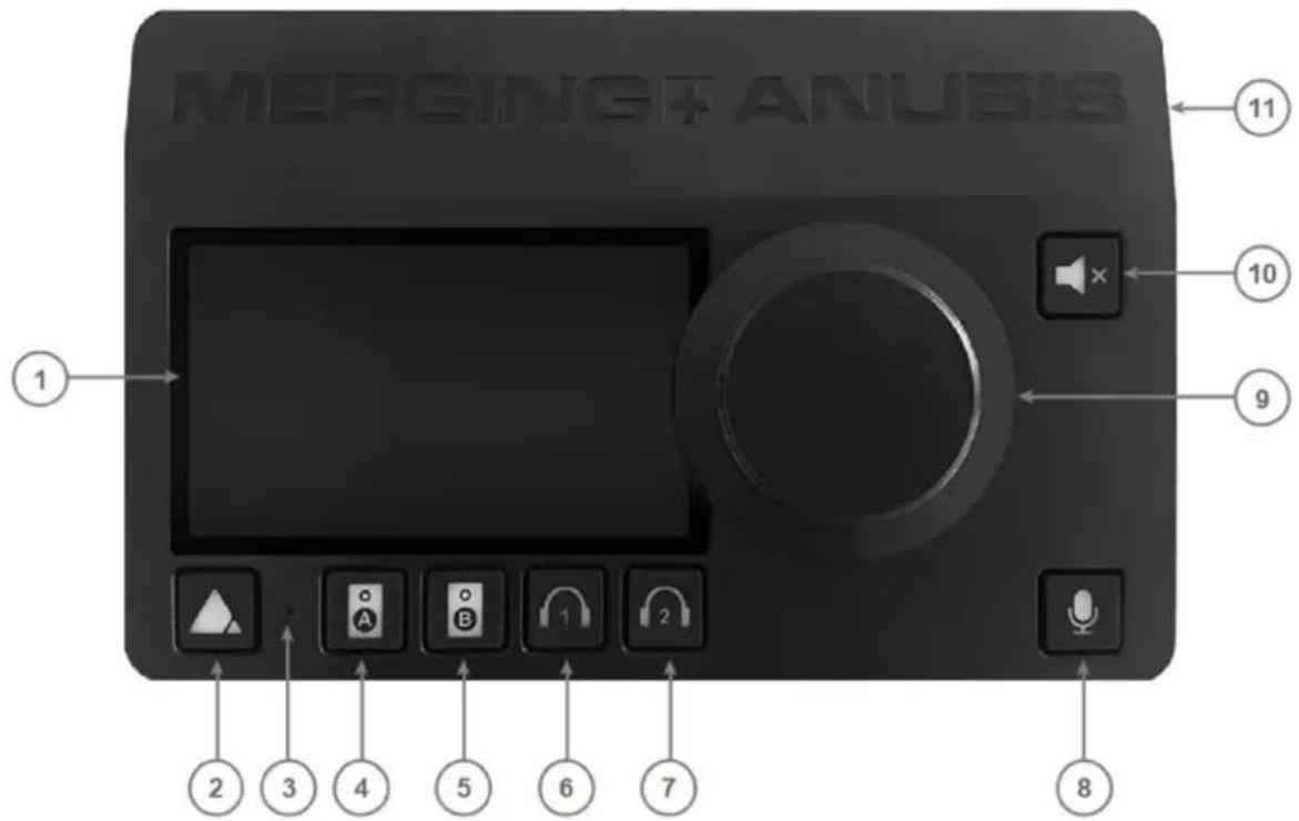
- TFT LCD: High resolution capacitive multi-touch display
- Home button: Access to Anubis display Main menu cycling and Home page / Settings access
- Built-in talkback microphone: Mono omnidirectional condenser capsule, located beneath the hole
Warning: Avoid touching the built-in microphone, or apply pressure while engaged.
Do not insert any object or liquid into the hole, or use a vacuum over the mic hole as it could permanently damage the microphone
- Speaker set A selector: Select the Speaker "A" to activate this monitor set, it will be activated once button is lit. The monitor set can be configured from the Anubis Settings>Monitors and can control the Anubis local outputs of your choice or the outputs of an external interface (RAVENNA/AES67 compliant)
- Speaker set B selector: Select the Speaker "B" to activate this monitor set, it will be activated once button is lit. The monitor set can be configured from the Anubis Settings>Monitors and can control the Anubis local outputs of your choice or the outputs of an external interface (RAVENNA/AES67 compliant)
- Headphones # 1 selector: Control over the Headphones 1 output Volume. When engaged and lit, use the main Rotary for local Headphone 1 volume control. The volume control can as well be adjusted remotely (from web access). The button selector can also control different monitor sets,
that can be configured from the Anubis Settings.
- Headphones #2 selector: Control over the second set of headphones (independent). Similar to Headphones #1.
- Talkback control: Pressing the talkback button will activate the talkback microphone (previously configured in settings). Its signal can be distributed to the Monitor set of your choice, whether this one is local or external (RAVENNA/AES67).
The distribution choice can be made from the Anubis Monitors Settings.
Note: The Anubis Talkback logic is not restricted to the built-in mic and is able to use any other microphone (including Phantom power condenser mics) as well. With even the possibility to setup by software two Talkback mics sending out to different cues or monitors.
- Rotary control: Multi-function encoder that can be used for Volume control over the selected monitoring output set or the Gain/Trim control over inputs or outputs. The Rotary control can also be used for selecting and controlling various Anubis settings (software).
- Mute control: The mute can be applied to any Monitor set. It can also be applied to external monitoring sets (RAVENNA/AES67 compliant) and mute the content of the outcoming streams.
- Anubis chassis: Premium machined and anodized aluminium
BOTTOM PANEL

Mic stand thread: 3/8" 16BSW European thread incorporated
Note: Americas 5/8" 27UN adaptor not included
SIDE PANEL

Fan: low noise that operates under thermal control. Can be set from Software Settings>General.

Warning: Do not insert objects into fan opening
BACK PANEL

Anubis SPS version

- Power switch: Sets the power of the device to On (pressed) or Off (released).
- Kensington Security Slot: Lock mechanisms for protection measure. Metal anchor not provided
- Power Supply: DC Power Supply connector with lock, to prevent accidental disconnection. The DC power input accepts a voltage from 9V to 15V, with a maximum power consumption of 18W.

Warning: Do not exceed the maximum DC input voltage or the unit may be damaged.
- RAVENNA/AES67 interface: RJ45 female receptacle with a locking EtherCon connector. A network interface adaptor might be required to connect to a USB-A, B, C or Thunderbolt port. The Anubis can be powered via PoE over this port.
* The Anubis SPS version features two (2) RJ45 connectors, for ST2022-7 support (network redundancy). The top port can be used to power the Anubis via PoE. The SPS Model can be set to network switch mode, allowing the daisy-chaining of one additional network device without the need for an external network switch.
- Dual functions interface: Switch between GPIO or MIDI (from General Settings)
■ GPIO: General-purpose input/output The GPO could for example be used to switch a LED Recording lamp on/off The GPI. Can be used with a footswitch on/off to select an input or for hands-free punch-in/out - MIDI: Musical Instrument Digital Interface protocol that connect a wide variety of electronic musical instruments, computers, and related audio devices.
- Line Outputs 3-4 balanced: Assignable balanced stereo TRS 1/4" jack outputs, that can be used for auxiliary speaker set, sub-woofer or for additional cue mix.
Note: Can be used in balanced (TRS) or unbalanced (TS) mode
- Main Line Outputs 1-2: Two Neutrik sockets on XLR balanced, that can be connected to a set of active studio monitors or power amp.
- Inputs 1-2: Two Neutrik combo sockets Mic/Line inputs on XLR and 6.3 mm - 1/4" TRS connector Note: Can be used in balanced or unbalanced mode
FRONT PANEL
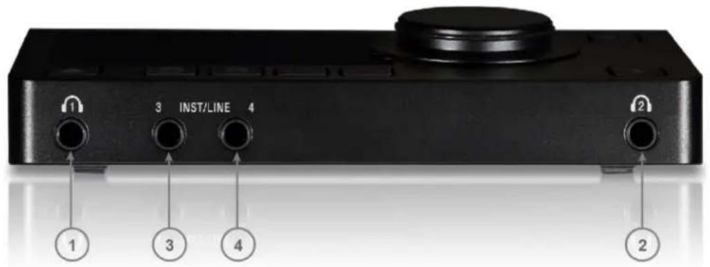
- Headphones #1: Independent headphones socket with Stereo jack 1/4" connector
Warning: Depending on the impedance of your headphone set, it is important to make sure that the Headphones output level is set accordingly. For further details, refer to the Anubis Settings > IO > Outputs Headphones description.
- Headphones #2: Independent headphones socket with Stereo jack 1/4" connector
3 & 4. Instrument/Line: 1/4" connector Jack can be connected to phone type (unbalanced or balanced) plugs for Hi-Z or Line inputs. For connection to a drum machine, synthesizer, electric guitar (active or passive pickups), electric bass (active or passive pickups), direct box, pedal board, or in order to connect an external analog processing chain.
Note: Connecting a jack into input 4 will override the built-in talkback microphone as both share the same input. It is recommended that you mute or cut input 4 when disconnecting the Jack to avoid potential feedback.
ANUBIS ANALOGUE I/O BLOCK DIAGRAM![graph TD subgraph Internal Bus & Processing System A["Line Out 1"] --> B["DA"] C["Line Out 2"] --> D["DA"] E["Line Out 3"] --> F["DA"] G["Line Out 4"] --> H["DA"] I["Handstone 1"] --> J["DA"] K["Handstone 2"] --> L["DA"] M["Handstone 3"] --> N["DA"] O["Handstone 4"] --> P["DA"] Q["Handstone 5"] -->…](/content/2026/07/1441624/images/7e6d2b7518bb47beb4d80556e9e54ab6dde2887ad03b84f5e3e13cd9e1de3f0a.jpg)
HOW TO CONNECT MERGING+ANUBIS
Connecting the Ethernet cable to the Network for RAVENNA use
The Network connection uses an RJ45 female receptacle with an EtherCon locking connector. A standard Cat5e, Cat6, or higher cable can be used. Anubis is supplied with a 3-meter Ethernet Cat6 cable; if a longer cable is required, it can be ordered from your Merging Technologies dealer. If using an EtherCon, align this one to the Network connector so that the small slot in the EtherCon connector body is facing upwards, then push the connector home until the lock clicks. To remove the cable, grasp the EtherCon cable connector body and push the tab above the Network input connector to release the lock, then withdraw the connector. Do not pull on the cable. If the lock release tab is not pushed sufficiently, the cable cannot be removed.
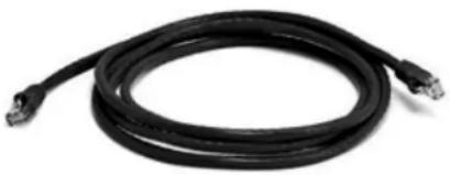
Figure 1: Cat5e or Cat6 Ethernet cable
Note: A network interface adaptor might be required to connect the Anubis RJ-45 cable to a USB Type A, B, or C port or to a Thunderbolt port of your notebook/computer.
For RAVENNA/AES67 Networks
If you have more than one Anubis or if you have another RAVENNA/AES67 device such as a Horus or Hapi, or a second system running RAVENNA/AES67 over the same network, it is highly recommended to use a Merging certified RAVENNA/AES67 switch and follow our configuration guidelines.

Merging's recommended Switches: RAVENNA/AES67 Certified Switches
Note: Switches for RAVENNA / AES67 must be in managed mode and properly configured.
How to connect a balanced line output to an unbalanced input
Contrary to Horus and Hapi DA8/P Line outputs, the MERGING+ANUBIS outputs are electronically floating (similar to transformer-based) and will therefore operate nominally with either Hi or Lo shorted to ground as would be the case when connecting to an unbalanced input.
To connect the MERGING+ANUBIS to an unbalanced input using the balanced outputs, it is recommended to do so as shown in Figure below.
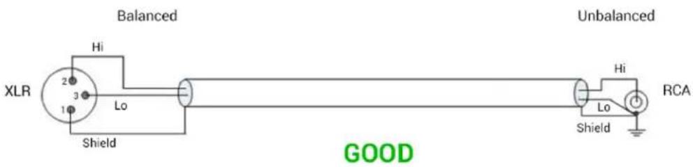
Figure 2 Correct balanced output to unbalanced input connection method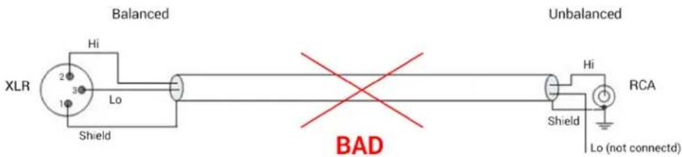
Figure 3 Incorrect balanced output to unbalanced input connection method
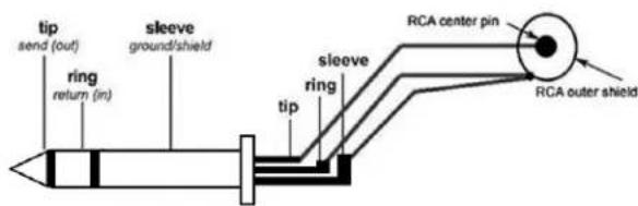
Figure 4 Correct balanced TRS output to unbalanced RCA connection method
Note: When driving an unbalanced input, make sure you set the line output level to the +18 dBu setting as the +24 dBu setting is only achievable when driving balanced inputs. This could otherwise cause distortion

Warning: Before you Power Up Anubis, it is recommended to lower the Volume of your Monitor Speakers (if those are connected) and to remove the headphones set from your ears.
DRIVERS INSTALLATION PROCEDURE
We recommend that you first read how to POWER Up your MERGING+ANUBIS and only then proceed with the information below.
Important. Make sure your Anubis has the most recent firmware installed. Verify the Firmware version by going to the Settings>Info Page.
Downloads and Procedures: https://www.merging.com/anubis/download
Windows PC - RAVENNA ASIO Driver or Merging Audio Device (MAD)
Prerequisites:
• Gigabit Ethernet network (A Gigabit Ethernet adapter is required in order to connect to a USB A, B or C or Thunderbolt port). • Windows 7 SP1 Pro - 64 bit, Windows 10 Pro - 64 bit or Windows 11 Pro - 64 bit - DAW ASIO compatible
Installation:
- Connect the Ethernet cable from the Anubis RJ-45 RAVENNA/AES67 port to the Ethernet network port (1Gb) of your computer.
- Download and install the Merging RAVENNA ASIO Driver v13 or the Merging Audio Device (MAD) 1.0 and ANEMAN v1.2.3 from https://www.merging.com/anubis/download. Pyramix MassCore users should only install ANEMAN.
- After the computer reboot at the end of the installation, open the Merging RAVENNA ASIO or MAD Panel and make sure that under "Local Adapter" the Ethernet Interface to which the Anubis is connected to is selected.
![RAVENNA ASIO Panel Merging/Ravenna ASIO Settings Local Adapter: 168,254,370,82) Buffer size: 120 [ms²] @ 44.34bit/6bit Latency: ○ 6/12/49 (AIS67) notes set HausNet/Arable latency accordingly ● 36/32/64 Number of Channels: 44.1/49k 85.2/99k 179.4/193k 332.6/394/000 Input: 0 0 4 2 1 Output: 0 0 4 2 1…](/content/2026/07/1441624/images/5424b5f8860e49a9bb300dd9f81835629be416901e90abca3983e8a92bc192aa.jpg)

RAVENNA ASIO PANEL MERGING AUDIO DEVICE (MAD)
- For further details on the other parameters, follow the RAVENNA ASIO guide or MAD online pages.
https://merging.atlassian.net/wiki/spaces/PUBLICDOC/pages/4819685/Merging+Audio+Device. for more details. You may configure those later.
- Make sure that your DAW is started and configured to use the Merging RAVENNA ASIO Driver or MAD. MassCore users should launch their VS3 Control Panel and have RAVENNA activated.
- Launch ANEMAN to connect the inputs and outputs of your choice between the Anubis and the RAVENNA ASIO driver (or MassCore). Follow the ANEMAN guide for more details.
Mac OS - VAD Premium
Prerequisites:
• Gigabit Ethernet network (A Gigabit Ethernet adapter is required in order to connect to a USB A, B or C or Thunderbolt port). • macOS Catalina 10.15.2 - Big Sur 11.x - Monterey 12.x Note: Mac M1's are supported as of VAD 3.0 and Monterey macOS as of VAD 3.1 and above - DAW CoreAudio compatible
Installation:
- Connect the Ethernet cable from the Anubis RJ-45 RAVENNA/AES67 port to the Ethernet network port (1Gb) of your computer.
- Download and install Merging's RAVENNA/AES67 VAD Premium (Virtual Audio Device version 2.0.39648 and higher) for Mac and ANEMAN for Mac (version 1.1.7 Beta2 and higher) from https://www.merging.com/anubis/download. Note: Since High Sierra, the drivers have to be approved. During the installation, you will have a "System extension blocked" message, go in the Security preferences to unlock the driver. Follow this page for more details.
- After the computer reboot at the end of the installation, launch the Merging RAVENNA/AES67 Panel from the System Preferences menu. Follow the Virtual Audio Device guide for more details.
- Launch ANEMAN in order to connect the inputs and outputs between the Anubis and the VAD.
- Open your preferred DAW and ensure the VAD is selected.

Warning: Recent Mac's are using 10Gb Ethernet Adaptors that are not certified for VAD usage. Please consider the use of an Apple or Belkin USB-C to ETH Gigabit adapter if you have such a Hardware Interface.
Linux OS - ALSA Driver
Prerequisites:
• Gigabit Ethernet network (A Gigabit Ethernet adapter is required in order to connect to a USB A, B or C or Thunderbolt port). • Linux kernel 2.4 (or above) 3.18 (or above for DSD support) • ALSA compatible application
Installation:
- Connect the Ethernet cable from the Anubis RJ-45 RAVENNA/AES67 port to the Ethernet network port (1Gb) of your computer.
- Download and Install the Merging LINUX RAVENNA/AES67 Driver.
- ANEMAN not being supported under Linux, RAVENNA/AES67 connections have to be made from the Advanced Settings RAVENNA pages.
For additional information contact alsa@merging.com
POWER SUPPLY
Anubis can be powered from a DC Power Supply (12V) and/or from PoE (Power over Ethernet).
Using the DC power supply source
- First connect the included Power Supply Mains adapter to an AC outlet.
Note: The DC power source can also be coming from a 12V battery.
- Connect the Power Supply to the rear panel of your Anubis.
* The Locking Power Supply requires that you align the two tabs on the power cable's connector to the notches on the Anubis input male connector.
Then rotate the barrel clockwise until latched, this will secure the connection and prevent accidental disconnection or a bad electrical contact.
![graph LR A["Tube with black cylinder"] -->|2.| B["9V to 15V"] B -->|3.| C["Cyclic Loading"] B --> D["12VDC - @ +"]](/content/2026/07/1441624/images/b6b66a83ec014d9f1b03e78b22f46516de640ae1206b2a5ff52bfe9416129dc2.jpg)
* The Locking Power Supply option is no longer manufactured as of the Anubis serials:
A600640 (Pro) and above
A650300 (Premium) and above.
The Anubis Locking Power Supply accessory remains optional at ordering.
Contact your Merging local sales representative for more details.

The DC power input accepts voltages from 9V to 15V, with a maximum power consumption of 18W. Do not exceed the maximum DC input voltage or the unit may be damaged. Merging highly recommends using the 12V power supply provided with Anubis.

Check that the power cable has the correct plug for the power outlet to which it will be connected. If the wrong mains cable has been supplied, do not attempt to modify it but contact your Merging Technologies dealer for a replacement.
Using the Power-over-Ethernet (PoE) source
Anubis can alternatively be powered from PoE (Power over Ethernet) or in parallel to the DC power, if redundancy is required.
PoE requirements:
- A suitable PoE+ equipped switch and/or external midspan PoE+ injector ■ IEEE 802.3at class 0 Power-over-Ethernet standard ■ 37.0 V (Min) - 48.0 V (Typical) - 57.0 V (Max) @ 1-2 A
Note: Recommended PoE switches are available RAVENNA/AES67 Certified Network Switches
Switching ON MERGING+ANUBIS
- Press the switch on the unit's rear panel next to the DC input, as shown on the Back-Panel figure.

- The Anubis soft buttons will light up orange when the unit initiates the boot-up sequence, and the TFT display will follow soon after. During this time the unit will perform a series of self-test and initialization routines.
- Once the Anubis TFT display shows the Home page, the unit is ready for use. Note: To turn OFF Anubis, press the POWER button to the Released state.
- Select your Anubis Mission. To navigate between pages, press the Anubis Home pyramid button. Hold the pyramid button for 1 second to return to the Home page.

The Anubis Home page provides access to the Settings and Preamps pages and the Logs (messages). The Home page is not in the 3 Main pages cycle. It can anytime be accessed by long pressing the Anubis Home button.
Legacy Home Page (Firmware 1.4.8 and prior)
New Home Page, Firmware 1.4.10 and above


More details on the Anubis main pages and settings in the Monitoring Mission chapter.
TOUCHSCREEN AND NAVIGATION
Use the following motions and gestures on your touchscreen to navigate the device.

Swipe from Right to Left on the TFT screen to view the following menus and pages.
Swipe from Left to Right on the TFT screen allows you to return to the previous pages

Swipe Up or Down to scroll through menus or various options

Single tap on the Anubis TFT to select or enable a function/option
Hold pressed for a period of 1 second to access or modify some parameters. This is required to access the Home page or to open a dialog box.
Anubis Rotary Knob
The Anubis Rotary Knob can be used for the Volume control, and to control the Preamps Gain, plus settings such as Trim, Delay, Brightness, numeric value entries and for navigation in various Anubis menus.
Generic: Turn the Rotary knob clockwise to increase values and turn the Rotary knob counter-clockwise to decrease values.
ANUBIS HOME PAGE
Legacy Home Page (Firmware 1.4.8 and prior)
New Home Page (Firmware 1.4.10 and above)
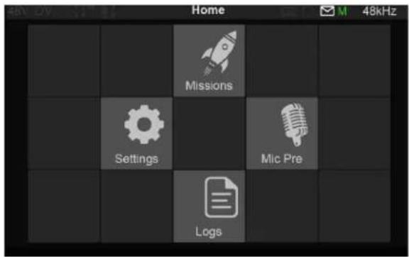

Scroll and select the Mission you plan to use.

Note: The Music Mission is available as of firmware 1.2.2 and above. Merging recommends that you update to the latest Anubis firmware.
The Commentary Unit Mission and Venue Mission are add-ons and will be available only with a valid license key.
Important: For Peering information, refer to the Peering chapter.
STATUS BAR
Displays information and notifications about the Anubis status.

48V: Will light up red if 48V Phantom power is active on an input channel.
CLP: Clipping peak detected. Clear the clipping by either tapping the meters section (PreAmps & Meters page) or use the Peak clear option available in the Meters page (PK) or in the Monitor Control section (refer to the Monitor Mission chapter).
OV: Overload detected in the Anubis built-in mixer. Typically summing multiple sources could cause an overload. Clear the overload by either tapping the Monitor page Peak or from the general Meters page (PK).
Input Cut: When lit, it will indicate that one or more Preamp channels are cut (muted) 1-2-3-4-TB.
Talkback: Built-in and/or routed input to the Talk 1 or 2. Active talkback will light up if engaged. Page title: Information related to the selected page.
GPIO: GPIO indicator for input and output, will light up if GPIO is received or transmitted.
MIDI IO: MIDI indicator for input and output, will light up if MIDI is received or transmitted.
Log: Lights up when a message or error has been received. Check message in Home page Log
Power Over Ethernet: (PoE) when active, the icon will be highlighted green
Synchronization status: M Master PTP or S Slave PTP clock, recommended for operations.
Yellow color S indicate lock in progress, wait for the lock to be green before operating Anubis.
Red color S indicates improper synchronization (operation not recommended check your setup.)
PTP Clock: The Precision Time Protocol (PTP) is used to synchronize clocks throughout a computer network. Also known as IEEE 1588, it is a protocol designed to synchronize real-time clocks in the nodes of a distributed system that communicates using a network. RAVENNA is based on and uses V2 of this IEEE standardized protocol. PTP Clocks allow for time resolution to the nanosecond.
Master: Indicates that the current Anubis is the PTP Master
Slave: The Anubis is slave to another PTP Master
If multiple Anubis are connected over the same network, one Anubis will be elected the PTP Master. A specific Anubis can require to be the PTP Master by enabling the PTP Master option in the Anubis>Settings>General.
Note: There is no guarantee it will be the Master as another device can have higher PTP priority/class.
Sampling Rate indication: e.g. 48kHz
LOGS MESSAGES
Important events, warnings and errors that occur during Anubis operations are kept in the Logs page, which can be accessed from the Anubis Home page. The reported messages in the logs page are intended at first to assist the user in case of operation issues. Refer to the Anubis Log Message Appendix at the end of the Manual for complete listing.
When a message is available the Anubis taskbar envelop will light up.

View the Logs messages by opening the Logs page from the Anubis Home page. Users can clear the logs errors by selecting the messages line and confirming their removal.
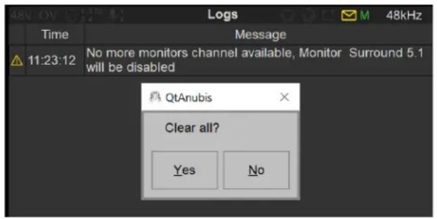
Example: The error reported above indicates that the total Monitoring channels has been exceeded. Solution: Disable some of your Monitors in order to have sufficient channels for a given Monitor Set
LOG MESSAGE APPENDIX
Listing of the Anubis log errors

Log Messages
| Message ID | Severity | Log |
| -2000 | Warning | Filter slope for speaker setcannot be applied due to some resource's limitation. Effective slope will bedB/octave (can also apply to EQ bands) |
| -2001 | Warning | No more talk channel available, Talkwill be disabled |
| -2002 | Warning | No more monitors channels available, Monitorwill be disabled |
| -2020 | Info | The selected Source cannot be summed with another one. This can happen when a DSD Source is already selected. |
| -2060 | Warning | Route fromtocannot be achieved (e.g. Mixed DSD/DXD formats cannot be monitored concurrently by Anubis) |
| -2100 | Warning | An unexpected behavior has occurred. Proper operation of the software cannot be guaranteed. Please contact the Merging support by providing the Debug Report. |
| -2800 | Warning | Bass management filter slope X dB/oct can't be recalled, to prevent an inaccurate result a 12dB/oct slope is applied instead. (for firmware 1.4.11 and below only) |
| -2005 | Warning | Channel X of monitor X cannot be fully compensated.Add EQ on this channel to solve delay alignment |
| -2032 | Warning | SoundId profile already exists too many times, it won't be appended to the collection."SoundId profile name " already exists. It has been renamed to "X" |
| -2034 | Warning | "Channels " not found in SoundID Profile : " X." of MonitorThe SoundID Profile has been disabled." |
| -2035 | Info | A Sonarworks multi-channels license is required for this SoundId Profile You can purchase one on shop.merging.com" |
| -2033 | Info | SoundId profile ID " X " already exists, it won't be appended to the collection |
| -2030 | Info | "Room Correction profile " X " has been deleted while it is currently used in Monitor |
| -2031 | Error | ERR "Room Correction Sound ID profile importation failed" |
| -2040 | Info | Channel:of monitorhas a bass management phase incoherency. Select a Linkwitz-Riley 24/48 dB/oct to solve the issue. |
| -2041 | Info | LFE channels present in some sources may produce a phase incoherency with the bass management. Select a Linkwitz-Riley 24/48 dB/oct to solve the issue. |
PREAMPS CONTROL
Selecting the Preamps icon will open the Anubis Inputs pages.
The Preamps Information bar on top of the controls displays: The Input Channel identification, the page position and the name of the Output Monitor set selected.

Note: More than three Preamps pages will be available if the Split Channels are enabled under Settings>Inputs>Split.
The PreAmps name can be edited with the Anubis Virtual Keyboard as of firmware 1.1.X by taping on the Input Channel ID name.
Combo 1/2: Control over the physical XLR/TRS Combo (6.3 mm / 1/4" connection) Mic/Line inputs located on the back panel of the ANUBIS

INPUTS OPTIONS:
48V: When enabled it will turn on the 48V phantom power for the channel 1 or 2 of the Anubis meaning that the Phantom power becomes active, typically needed for condenser microphones.
Note: Only active on channels set to Mic (Anubis XLR/Combo Inputs 1-2).

Warning:
The 48V power MUST be turned off prior to changing the connection in certain
Patch bays. Many such patch bays short the Hot, Cold, or both signals to Ground during insertion or removal of the jacks, with the risk of permanently deteriorating the protective resistors in the input of the preamp circuitry. If an AD module input circuitry is damaged following such a short, it will end up
permanently having inaccurate gain levels, distortion, or even no signal at all on some channels. Such damage is not covered by our warranty.
Mic
Mic/Line: Switches the input between the Mic-Pre amplifier and the Line level circuitry. The option will show the current input signal path it is set for (Mic or Line).
Line
The Line input sensitivity, switch from Mic to Line level and impedance.
Line Fader of 0 dB means 0 dBFS for +24 dBu analog signal level present at
the Line input.
Line Fader of +6 dB means 0 dBFS for +18 dBu analog signal level present at the Line input.
Line Fader of +20 dB means 0 dBFS for +4 dBu analog signal level present at the Line input.
Line Fader of +66 dB means 0 dBFS for -42 dBu analog signal level present at the Line input.
Note #1: The MIC, Line, and Instruments inputs are stored as independent parameters, meaning that switching from Mic to Line to Instruments and vice versa will load their stored gain (sensitivity) value.
Note #2: The ANUBIS Premium has been designed in order to be able to benefit from the +3.1 dB SA-CD headroom offered by DSD, as per the Scarlet Book standard. Therefore, a minimum of +6 dB gain is required on the mic preamp or line input. This gain is applied in the digital section post AD just prior to the sigma delta 1-bit modulator. It is automatically applied as soon as the ADs are switched to DSD (64, 128, 256FS) and is visible in the preamp page. The gain can be adjusted between +0 dB and +66 dB in DSD mode. In Line mode, with a gain of +6 dB, an input of +21 dBu will generate a signal of +3 dB SA-CD. In Mic mode, with the same gain, an input of +9 dBu would generate a signal of +3 dB SA-CD.

Gain: Tap the channel you wish to adjust. When the Gain is highlighted, the Anubis Rotary Control lets you adjust the value in 0.5 dB steps.
The Gain range goes from 0 dB to +66.0 dB. Turn the Rotary knob clockwise to increase the Gain value and turn counter-clockwise to decrease the Gain value.

Link: Tap to link a pair of input Preamps and control their settings simultaneously. Changes will be applied to both channels while keeping any Gain value offset.

None: Max Mic input level +12dBu for 0dBFS (when Gain set to 0)
Pad: Attenuates (lowers) the mic input signal level by 12 dB > Max Mic input level +24dBu
Boost: Increases (boosts) the mic input signal level by 12 dB > Max input level 0dBu Note: Useful for Ribbon Microphones that have low output.
Polarity: Polarity invert option. When lit, it inverts the polarity of the selected input signal.
80 Hz: Low cut filter 80 Hz. Second order, 12 dB/octave.
Cut: This option allows the operator to Cut a channel input. By example to Cough Cut a microphone input. It can also be used to avoid potential noise when connecting or disconnecting an XLR or Jack input.
Lock: Enabling the lock option will prevent the input parameters being changed. This could be useful for safety or in order to maintain a calibration for an external analog processing chain.
Meters: The Meters default display scaling range goes from -90 dBFS to 0 dBFS.
Note: Refer to the General Settings in order to configure and adjust the Level meter color range (Peak, Alignment and Decay time). Refer to the DSD section for Meters.
Peaks: The top Red led of the Preamp metering will indicate that a Peak has occurred. In order to clear the Peak display, simply tap on the meters VU to clear the Peak.
Output: The Output meters located on the far right of the UI display the Output level and metering of the selected Monitor whether it is a local Monitor (Main, Line, Headphones 1, Headphones 2) or an over the network Monitor set.
The name of the selected Output is displayed at the top of the meters.
Note: Despite the display being two channels, the peak of all channels, split in left and right channels is indicated.
Inputs 3-4 Instruments/Line:
Swipe from right to left on the TFT screen to access the Anubis Inputs 3-4.
The location indicator will show the second Preamps page.


The Instruments (Hi-Z)/Line inputs 3-4 are the ones located on the front panel of the ANUBIS on 1/4" connectors (6.3 mm). This second Preamps page will give you control over those Preamps.

The Preamps controls for inputs 3-4 are similar to inputs 1-2 but will apply to Hi-Z, Instruments, or Line inputs types only. Thus, the 48V Phantom power and Pad/Boost options are not available for the Anubis inputs 3-4.
Note: Input 4 is shared with the Built-in Talkback. Connecting an Instrument or Line input jack into this input will deactivate the built-in Talkback (Channel 5).
It is recommended when you pull out a Jack out of input 4 to either Mute your Monitors or Cut the Input 4 preamp signal prior to pulling out the Jack to avoid an accidental short feedback situation between the built-in talkback Mic and the Monitor set.
Input 5 Built-in Talkback:

Swipe from right to left on the TFT screen again to view the Anubis Input 5 that is dedicated to the built-in Talkback microphone.

The Preamps controls for Input 5 will control the built-in Talkback microphone.
Notes: The Input 5 Built-in Talkback is shared with Input 4. Connecting an Instrument or Line input jack into this input will deactivate the built-in Talkback (Channel 5).

Swipe on the TFT screen from left to right in order to return to the previous Inputs Preamps pages.
Note: More than three Preamps pages will be available if Split Channel is enabled under Settings>Inputs>Split or if you Peer PreAmps, refer to the Peering chapter for details.
Remote control of the Anubis Mic Preamps using ProTools DAW.
Mac: User should refer to the VAD User Guide for details on the procedure to follow Virtual Audio Device guide.
PC: Users must refer to the RAVENNA ASIO Guide or Merging Audio Device (MAD) guide for details on the procedure to follow.
Remote MIDI preamps limitations (Boost, Link, Cut):
Boost: Remote MIDI Preamps control does not support the Anubis Boost Preamps option. It will be interpreted as a Pad. For the moment it is recommended to set this parameter locally on the Anubis Preamps.
Link and Cut: Remote MIDI-Preamps control do not support the Anubis Link Preamps option. Users can use Stereo Inputs. The Cut option will also need to be used locally on Anubis.
DUAL GAIN 32bit CIRCUITRY
While based on the extensive experience of Merging's Horus and Hapi Preamp and AD converter design, the Anubis engineered Dual Gain 32bit A/D circuitry takes Analog/Digital Conversion design one step further. While using 2 A/D converter channels per input as in the Horus & Hapi design, those two A/D converters are not driven in parallel by a single Preamp stage but the Anubis provides for two gain-ranged separate Analog front-ends, each driving its own A/D converter channel. The signals out of each AD converter is then combined seamlessly in an optimal way to both expand the headroom and lower the noise floor, providing huge dynamic range with ample headroom. One main advantage of this topology is the considerable additional freedom and safety implied by not having to spend much time and effort to adjust the input Gain to maximize the program level range between input circuitry noise and clipping level of the A/D converter. An important side benefit of that topology is also the total absence of any clicks when adjusting the Preamp Gain steps, as those can be entirely processed in the digital domain.
![graph TD A["8V"] --> B["6.8 kΩ"] B --> C["0 dB / +12 dB / +24 dB"] C --> D["High Gain"] D --> E["A/D"] E --> F["Alternation"] F --> G["Internal Bus & Processing System"] H["22 kΩ"] --> I["Institute 3-4"] I --> J["1 MΩ"] J --> K["High Gain"] K --> L["A/D"] L --> M["Alternation"] M --> N["Internal Bus…](/content/2026/07/1441624/images/883e31d8d5ccf913331fc58774c5695d981f9d9e8a75d6480fe1b947b505c4ab.jpg)
Figure 4 Dual Gain Block Diagram
SPLIT CHANNEL
As seen on the right side of the above block diagram, the Anubis AD front-end topology gives also additional flexibility by offering a split channel functionality, where every input channel has a separate split gain control for sending them to different paths.
Use Case examples:
- Typically, an AD could be used for the recording device and have its split channel used for the EOH.
■ Independently control the FOH & Monitoring Microphone Gains without any conflict
- The Split channel gives the operator the possibility to cut an input signal to the FOH while monitoring the same channel split that would be routed to another Monitoring set (e.g. Headphones). For signal check, changing a defective cable or searching for a proper sound or instrument FX, all this while muting the FOH feed.
- Possibility to record a duplicate of the input channel at a different input gain level (for backup or peak-safe recording)
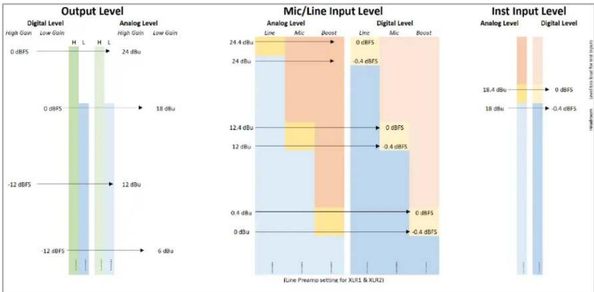
Analog levels and Digital levels (after A/D conversion)
For Mic/Line and the Inst/Line inputs of Anubis.
ANUBIS VIRTUAL KEYBOARD
| < Monitors Main 1-2 | |||||||||
| CANCEL | Main 1-2 | OK | |||||||
| 1 | 2 | 3 | 4 | 5 | 6 | 7 | 8 | 9 | 0 |
| Q | W | E | R | T | Y | U | I | O | P |
| A | S | D | F | G | H | J | K | L | - |
| SHIFT | Z | X | C | V | B | N | M | / | DEL |
| + | [ | ] | SPACE | < | > | ← | → | ||
As of Firmware 1.1.8 and above, the Anubis includes a Virtual Keyboard. You can use the onscreen keyboard to add and edit text.
The Anubis keyboard is only available for the moment with a Qwerty US layout.
The Anubis Virtual Keyboard is available to edit.
■ Source Names - Monitor Names ■ Presets Names ■ PreAmps Input Names ■ More to come....
The Virtual Keyboard is available to edit Anubis entries identified in blue. Open the onscreen keyboard by tapping a blue editable text or field.

Virtual Keyboard - Key Functions.
Select a word: Double-tap the word with one finger.
Select a sentence: Tap and drag your finger up to desired selection range.
| < Monitors | Main 1-2 | 48kHz | |
| CANCEL | Main 1-2 | OK | |
Use the Virtual Keyboard key to enter the new desired name or entry.
| < Monitors | Main 1-2 | |
| CANCEL | Main Monitors 1-2 | OK |
OK: Tap the OK key to confirm the new edited text entry, this will automatically close the Virtual Keyboard and
Cancel: Tap key to cancel the Edited text and close the Virtual keyboard.
SHIFT: Enable to access the lower-case keys and special characters.
| < Monitors Main 1-2 | |||||||||
| CANCEL | Main Monitors 1 &2 | OK | |||||||
| ! | @ | # | $ | % | ^ | & | * | ( | ) |
| q | w | e | r | t | y | u | i | o | p |
| a | s | d | f | g | h | j | k | l | _ |
| SHIFT | z | x | c | v | b | n | m | ? | DEL |
| = | : | ; | SPACE | , | . | ← | → | ||
SETTINGS
The Anubis Settings are accessible from the Anubis home page, by giving a long press on the Anubis Home button.
This will open the Settings page


Scroll up or down to view and navigate through the settings entries.

SETTINGS CATEGORIES DESCRIPTION

GENERAL SETTINGS
Note: The General Settings are displayed on a black background as of Firmware 1.4.4 and above.
Sample Rate

Sampling Rate
Selector to the different sampling rates, available from a drop-down menu.
Anubis Pro: 44.1kHz, 48kHz, 88.2kHz, 96kHz, 176.4kHz, 192kHz
Anubis Premium: 44.1kHz, 48kHz, 88.2kHz, 96kHz, 176.4kHz, 192kHz, 352.8kHz (DXD), 384kHz, DSD64, DSD128, DSD256
DSD requires the Anubis firmware v1.0.16 and higher.

Auto
Auto Sampling Rate mode, when enabled, will make Anubis automatically follow the sampling rate given by a RAVENNA/AES67 source provided by either; ASIO, Merging Audio Device (MAD) Virtual Audio Device (VAD), MassCore or another interface with PTP clock. Enabled by default.
Example 1: User using an external player (such as a DAW) can enable the Auto mode so that Anubis automatically changes its sampling rate according to the project settings.
Example 2: This Auto setting is also useful in a network configuration following the RAVENNA ASIO/Merging Audio Device (MAD)/Virtual Audio Device (VAD) settings, where Anubis will adapt its sampling rate automatically.
Both examples above are valid provided at least one RAVENNA ASIO, Merging Audio Device (MAD) or Virtual Audio Device (Core Audio) stream is connected to an Anubis Source.
Note: If using ANEMAN with a Sampling Rate Zone, the device on the Crown will decide the master sampling rate of all the devices present in the Zone.
In such a case, it is recommended to disable the Anubis Auto Sampling Rate mode to avoid conflicts over the sampling rate of the non-Crowned devices at a given moment, since those could potentially cause sampling rate flickering.
Frame Mode

Latency
Modes available in samples: AES67 (6), AES67 (12), Ultra (16), Extra (32), AES67 (48)* & Low (64). The selected mode will determine the device latency over a RAVENNA network. When multiple RAVENNA devices (e.g., Anubis) are connected over a network, they should be configured to adjust themselves to the lowest latency that can be globally achieved.
* Ex-factory default mode
Clock
About the PTP Clock: The Precision Time Protocol (PTP) is a protocol used to synchronize clocks throughout a computer network. Also known as IEEE 1588 or IEC 61588, it is a protocol designed to synchronize real-time clocks in the nodes of a distributed system. RAVENNA is based on and uses V2 of this IEEE standardized protocol. PTP Clocks allow for time resolution to the nanosecond.

PTP Master
If multiple AoIP devices are used in a network environment, Anubis will try to be elected as the PTP Master priority when enabling this setting, using the Best Master Clock Algorithm (BMCA):
Note: Non-Merging devices might not consider Anubis as the PTP Master.

PTP Status
Information on the Anubis PTP status. Save or Master indicator and Unlock, Locking and Lock status.

ASIO Clock
Auto: The ASIO clock will be generated by the Anubis which will be PTP Master.
On: The ASIO clock will always be generated by this Anubis, whoever the Master.
Off: The ASIO clock is never generated.
Note: Set to Off only if you are sure that no Anubis will be PTP Master, or if you are configured for a Unicast (point-to-point) workflow.
Interface Controls

Brightness Display
Adjust brightness of the TFT display using the Anubis rotary encoder to increase or decrease it.

Buttons Intensity
Adjust brightness of the Anubis physical buttons by using the Anubis Rotary Knob to increase or decrease the intensity.
Fan

Fan
Cooling Mode: Settings are available for either Low, Mid or High Cooling. This affects the threshold at which the fan will start to operate, with reference to the temperature measured internally. While there is no universal preferred setting, we recommend that unless noise levels are a concern, you leave the setting on Mid for adequate cool operation and protection.
- Low: Fan starts in average above 52°C
- Mid: Fan starts in average above 42°C
- High: Fan starts in average above 32°C
When above these thresholds, Fan always starts at the lowest speed (minimum noise), and gradually increases proportionally to the measured temperature.
Note: The Anubis will shutdown automatically as a precaution when reaching a temperature of 66° C.

Stop on Talk
Enabling the Stop on Talk option will stop the Fan when engaging the Anubis Talkback button. Once released, the fan will start back if it has to (depending of the measured temperature)
Network Settings

Obtain an IP Address
Manual: Tap the address field you wish to edit and select the value using Anubis Rotary Knob Auto: The IP address will be automatically attributed using ZeroConf/Auto-IP mechanism (address range 169.254.x.x if no DHCP server is present)
Note: By default the Anubis IP setting is set to "Auto" configuration mode
For details on the Anubis SPS model refer to the SPS Manual section here.
IP address
Set the IP Address for the Anubis unit by using box selection and changing the value using the Anubis rotary knob. Available only with IP Settings = Manual
Default: 169.254.x.x
Subnet mask
Set the Subnet Mask (subdivision of an IP network) for the Anubis unit by using box selection and changing the value using the Anubis rotary knob. Available only with IP Settings = Manual Default: 255.255.0.0
Default gateway
Computer network node using the Internet Protocol Suite that serves as the forwarding host to other networks when no other route specification matches the destination IP address of a packet. Default: 0.0.0.0
Apply & Reboot
Once changes have been made to this section, you must press this button to save the settings and power cycle the Anubis unit, shutdown and reboot.
Date & Time
Anubis includes a real-time clock that is battery powered even in the absence of external power.

TimeZone
Select your local timezone from the dropdown menu
Date
Set the date by tapping each field (Day: Month: Year) one by one and using the Anubis Rotary Knob to adjust it.
Time
Set the date 24-Hours format by tapping each field (Hours: Minutes: Seconds) one by one and using the Anubis Rotary Knob to adjust.
Note: The Date and Time changes will be saved once you exit the Anubis Settings or if you Save the current configuration from Settings>Exit>Save

METERS Settings

Hot (PCM)
Sets the metering level Hot range (white). If set to 0dB this will mean clipping.
Range -2dBFS to 0dBFS
Default: -0.2dBFS
Note: When reaching a level of 0dBFS (digital clipping) the meter top led will display a Red peak.
Hot (DXD/DSD)
Sets the metering level Hot range (white). If set to 0dB this will mean clipping.
Range: -2dB to +6dB SACD
Default setting: +2.8dB SACD
Reminder: DSD users benefit from a +6dB headroom in DSD with distortion starting slightly and progressively from 3.1dB upwards and clipping once reaching +6dB SACD.
Alignment (reference level)
Sets the metering level Alignment range (light-gray).
Range -24dBFS to 0dBFS
Default: -18dBFS
Decay Integration Time
Sets the rate at which the level meter display decays after the level falls below the most recent Peak.
Choices: OFF - 25 ms/dB - 50 ms/dB - 75 ms/dB - 100 ms/dB
Default: 25ms/dB
Peak Hold
Enabling Peak Hold allows the meter to continue displaying the highest signal level permanently, until it is exceeded by an even higher peak. This is very useful, as it gives clear indications of where and how hot peaks are, but still allows monitoring of the current signal level.
PRESETS Settings
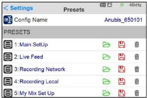

Preset Configuration Name. Identify your current configuration.

Full configuration save and recall for instant switching between various projects or configurations. Anubis ex-factory comes empty of presets, gray folders.

Load: 18* presets banks of different Anubis configurations can be loaded (one at a time)

Save: 18* presets banks are available to store different Anubis configurations
* 18 presets are available as of Anubis Firmware 1.1.11

Empty a preset by selecting the trash and confirming is deletion
A prompt message box will ask you to confirm the save or load of a preset.
During the Preset loading the Anubis Mute button will blink muting all monitors for a short period
Rename your Preset by using the Anubis Virtual Keyboard (as of Firmware 1.1.18 and higher). Simply tap on the Preset name entry to open the Anubis Virtual Keyboard. Refer to the Virtual Keyboard here for more details.
Note: An unlimited number of Presets can be save and loaded from the Web Access (external Disk)

Warning: A Reboot to Factory will reboot the Anubis to the default factory settings, the current configuration will be lost, but all the saved Presets will be kept and can be reloaded.
MONITORING Settings

The Monitoring settings are the central part of the Monitoring Mission. This is where you can configure the incoming Sources and outgoing Monitor sets, and configure their routing.

The first step is to configure your Sources (e.g., DAW or External RAVENNA Device) prior to deciding how you will monitor those. By default, Anubis comes with pre-created sources that consist of the current Anubis physical inputs: Mic/Line (Back Panel Inputs 1-2) and INST/LINE (Front Panel inputs 3-4), with an additional DAW Source ready to listen to your DAW Playout, upon a first connection within ANEMAN. The internal Sources are already patched to the Anubis mix engine, so that you can immediately use them for monitoring purposes. You are free to remove any of those pre-configured and/or to create your own additional Sources at any time.
Anubis ex-factory comes with some pre-configured Sources (such as DAW 1-2). Users are free to add and create their own sources or edit the present ones. 128 channels @ 1FS (44.1/48kHz) are available to connect those Sources.
Sources entry page details.

Note: Use the arrow up or down to move a source to a new ordering position. This feature is available as of Firmware 1.1.x and higher.
Two different types of Sources can be created:

Create New Source
Standard Sources: for example, for a DAW playback, External Multichannel device, Physical Inputs

Create New Stream Listener
To monitor the streams available over a RAVENNA/AES67 network, streams have to be compliant with RAVENNA or AES67. Once available, Anubis will see those and allow the users to select them for monitoring purposes.
Enter a Source configuration by tapping the Source line or the source name.

Select to delete a Source upon confirmation in message dialog.

Enable or disable a source.
Disabling a source will hide it from the Main Anubis menu pages. Doing so will not delete the Source but simply hide it with a gray icon – it can be re-enabled at any time.

Name
Name the Source by tapping the Blue text entry to open the Virtual Keyboard (available as of Firmware 1.1.8 and above)


Type
Select the source channel type. Predefined sources are available from mono to 22.2 Channel mappings. Scroll to see all available entries.

Note: As of the Anubis firmware 1.0.13 and higher, users are no longer restricted to the predefined name listing and can rename their Sources and Monitors with the Anubis Virtual Keyboard or from the Web Access page. Refer to the Virtual Keyboard here or Web Access chapter for more details here.

Trim
Trim the level of an entire Source, apply a trim by turning the Anubis Rotary Knob.
Range: -36dB to 12dB
Note: Trim is after the initial analog gain stage, so if the channel input is clipping, Trim cannot fix it.

Channels

Number: Channel numbering of the Source
Type: The channel type is predefined in accordance with the selected Source Type Patch: Configure the Source routing by patching each of the source channels. The Patch numbering in the Patching dialog starts with the Anubis Hardware Input sources followed by the external sources Streams, such as paired device streams from another Anubis, Horus or Hapi, ASIO, MAD, VAD or MassCore streams. Scroll to view the entire listing.
Single
Patches a single channel at a time.
Auto↓
Patches automatically the channels following the selected one (downwards). Quick way to patch multichannel Sources or Monitors.
Note: can be applied to None, to un-patch all channels.
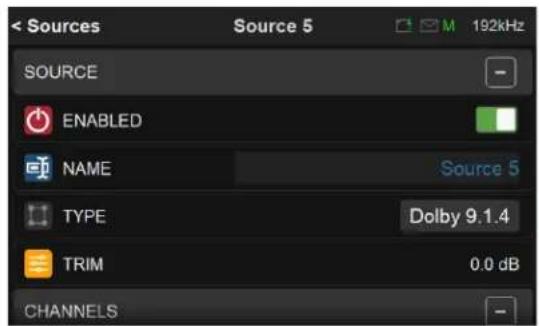


Figure 5 Example: Patched Source
Stream Listener Source
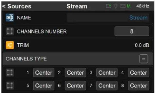
New as of Firmware 1.4.6
Number of Channels:
2, 8, 16 channels are available for the Stream Listener.
Note: RAVENNA/AES67 channels Sources of lower channels count are accepted.
Channels Type:
Select the type for each of your channels. By default the type is set to Center for each channel. If a channel type is set to None, the channel will be muted.
Wildcard Filter:
A stream filtering filter
![Sources Stream 48kHz STREAMS FILTERING WILDCARD FILTER Wildcard Matching: Show only AoIP sources matching the wildcard scheme defined as: - Any character represents itself apart from those mentioned below. - ? Matches any single character. - * Matches zero or more of any characters. - [...] Sets of…](/content/2026/07/1441624/images/b947f9757481888bafe611bc325d15ce994a875fd511bce0aff27bea73dac679.jpg)
c Any character representing itself apart from those mentioned below. Thus c matches the character c.
? Matches any single character.
* Matches zero or more of any character.
[...] Sets of characters can be represented in square brackets.
Examples
| Wildcard | Streams name filter that | Example of Streams matching |
| *Drum* | Contains “Drum” anywhere | Drum OH; my Drum; Input Drum 5, ... |
| Anubis* | Begins with “Anubis” | Anubis 42; Anubis Mic 1; ... |
| A?.HDMI | Begins with A followed by any single character followed by “.HDMI” | A3.HDMI; Ax.HDMI; ... |
| Input_[1][1-4] | Begins with “Input_” followed by 11 or 12 or 13 or 14 | Input_10; Input_14; ... |
| *Cello?[123] | Contains “Cello” followed by any single character followed by 1 or 2 or 3 | CelloA1; Cello_2; My Cello03; ... |
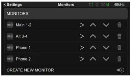
Configure your Monitoring sets, whether you plan to use the Anubis hardware output sets for your Studio Monitor Speaker, Headphones, Cue Mix or to Remotely control the outputs of an external compatible device RAVENNA/AES67 (e.g. Horus or Hapi).
Monitor entry page details

Note: Use the arrow up or down to move a Monitor to a new ordering position. This feature is available as of Firmware 1.1.x and higher.

Create new Monitor
Create a new Monitor set that can be customized for your needs.
For example configure the Anubis Main (1-2) outputs to control the volume of your DAW Source through the Anubis Monitoring Engine.
Enter a Monitor configuration by tapping the Monitor line or Monitor Name

Select to delete a Monitor set upon confirmation in message dialog

Enable or disable a Monitor
Disabling a Monitor will hide this one from the Main Anubis menu pages. Doing so will not delete the Monitor but simply hide it with a gray icon, it can be enabled back at any time.

A disactivated monitor Set will show a Red muted speaker icon

Name
Name the Monitor by taping the Blue text entry to open the Virtual Keyboard (available as of Firmware 1.1.8 and above).

NAME
Speaker A
Note: As of Anubis firmware 1.1.8 and higher, users are no longer restricted to the predefined name listing and can rename their Sources and Monitors with the Anubis Virtual Keyboard or from the Web Access page. Refer to the Virtual Keyboard here or Web Access chapter for more details here.

Mode
Define your Monitor by selecting one of the 3 available Monitor Modes.
- Speaker Set: Recommended to be used for Speaker Sets (e.g. Stereo Monitors)
- Headphones: Recommended to be used for Headphones Sets monitoring
- Cue: Recommended to be used when a specific summation of Sources is needed on a designated Monitor set or when recording to produce a low-latency Cue mix for the performer foldback.
Important:
Monitor sets have different properties, refer to the Monitors Types and Features table here. Speaker Sets and Headphones will monitor the same Sources selection. In order to have an independent monitored Source selection it is mandatory to use a Cue. For more details refer to the table detailing the different Monitor mode possibilities and constraints, available in the Sources vs. Monitor section.
Note #1: Connecting only one input to a Stereo Source will hard pan this source monitoring to either the left or right channel depending on the input used and Monitor set. It is recommended to change the source type to Mono if using only one input in order to have this source monitored to center channels.
Note #2: Monitors must be selected on Anubis in order to see the IO connections in ANEMAN

Mon to Cue inactive (only available for Cue mode)
By default inactive, so all Cues are over-routed by the Speaker Set/Headphones current source selection when MON>CUE is selected on the Monitor Controls.
When enabled it will prevent the operator to override the Cue Mix and so will not send the Speaker Set/Headphones Sources to Cue listener.
Note: When enabling Mon to Cue only the Sources selection will override the Cue Monitor. The Speaker Set controls: Mute, Solo, Solox, Polarity, Downmix, Ref and Dim will not be injected in the Cue.

Trim
Trim the level of a Monitor set, apply by turning the Anubis Rotary Knob.
Range: -36dB to 12dB (as of Firmware 1.1.x)
An individual Channel Trim is available for each channel (refer to the Channel description below) Note: The Trim can also be set directly from the Meters page. DSD/DXD trims range max level depends of the applied trims.
For example, if you trim a monitor to +3 dB, the max volume will be set to -3dB for that monitor. On the same monitor if the trim on the L channel is +2 dB, the max volume will set to -5 dB.

Button
Assign your Monitor set to the button of your choice by selecting one entry from the drop-down dialog. You can choose between one of the Anubis hardware monitoring buttons available; Speaker A, Speaker B, Headphones 1, Headphone 2. Or by choosing one of the 4 Virtual Keys available, a Virtual Key will then be added on the Anubis TFT. Only one Button /Monitor can be chosen. If an already assigned Button is chosen, it will automatically set to None the Monitor selected
| None |
| Speaker A |
| Speaker B |
| Headphone 1 |
| Headphone 2 |
| VKey 1 |
| VKey 2 |
| VKey 3 |
| VKey 4 |

Type
Select the Monitor set type. Predefined Monitors are available from mono to 22.2 Channels mappings. Scroll to see all available entries.


Channels

Type: The channel type is predefined in accordance with the selected Monitor Type
Solo: Solo the channel
Trim: A channel trim exclusive to each Monitor Set is available for speakers. Range: -12dB to 0dB.
Delay: Set a delay to the speaker of your choice. Apply by turning the Anubis Rotary Knob. Range: 0ms to 150ms by steps of 1ms
Note: Audio will cut on all delayed channels when enabling/disabling a delay on a channel. The delay incrementation value starts from 1.4ms.
EQ: Press the EQ button to access the EQ UI. Refer to the EQ chapter for more details.
Link: Link the EQ channels to apply the same parameters to the linked channels.
Bypass: Bypass the EQ to monitor with or without the EQ.

Patches Figure 6 Example: Configured Patch Monitor
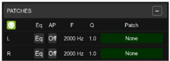
Type: The channel type is predefined in accordance with the selected Monitor Type.
EQ: Access to the Parametric EQ page; the button is enabled when the EQ is active.
AP: All Pass Filter ON/OFF.
F: Frequency target of the All Pass Filter.
Q: Slope of the Phase on the All Pass Filter.
Note: This EQ is recommended when using speakers from different brands within a monitoring setup to align the phase introduced by different types of transducers/filters.
Patch: Configure the Monitor routing. Users can patch an Anubis Hardware Output Monitor, an external source (e.g., Paired device) or RAVENNA/AES67 Stream. The Patch list starts with the Anubis Hardware inputs followed by the RAVENNA/AES67 Stream; the latter cannot be created from the Anubis. Use ANEMAN to do so. Scroll to view the entire listing.
Single
Patches a single channel at a time.
Auto↓
Patches automatically the channels following the selected one (downwards). Quick way of patching multichannel Sources or Monitors.
Output Duplication in Patches section as of firmware 1.4.10 and above It is possible to Add additional outputs to a given Monitor output, the same control will apply to it

ANUBIS EQ GUIDELINES
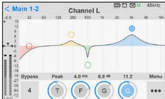
12 Bands support with Firmware 1.4.3 and below
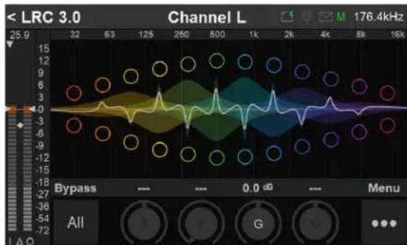
24 Bands support as of Firmware 1.4.6 and above
New Anubis EQ for Monitors
The Anubis EQ is built on the existing and universally acclaimed quality of the Pyramix EQ-X and offers Extreme definition filtering at sampling frequencies up to DXD.
This new EQ support for Monitors is a twelve band fully parametric EQ with independent control of filter type, gain boost and cut, frequency, and Q factor (bandwidth) for each band. With notch, low cut, Hi Cut, peak and shelving filter types available. The state space filter design of this extreme definition equalizer has been specifically optimized to deal with the highest audio resolutions while still permitting very low noise & distortion, typically offering a THD+N of better than -110dB, throughout the entire audible (and even non-audible) range. Of course, this new digital filter's topography, while designed with high sample rate in mind, also offers the extra benefits and low noise to 1FS equalization.
EQ can be applied to any monitors type (speakers set, headphones and cues). In case of speaker set, multiple speakers set having the same routing with different equalization can be set. In that situation the EQ resources are not cumulated but shared. This allows a complex equalization for each speaker set (maximum total of 84 bands are available).

Important: The Monitor EQ are supported as of Anubis Firmware 1.1.8 and higher.
EQ SIGNAL FLOW
PCM 44.1 kHz to 384 kHz![graph TD A["Starting in 1.4 (Austes 8 or Subis 5K)"] --> B["Loan"] B --> C["Up to 128 channels @17.0, Up to 128 channels @19.3, Up to 64 channels @19.3, Up to 102 channels @19.3"] C --> D{Biomass} D --> E["Mething"] E --> F["Loan"] F --> G["Totout"] G --> H{Tetraest} H --> I["Downstream"] I --> J["D…](/content/2026/07/1441624/images/8aed819b675f1017f7063f8b98d198c4bf8854299b502a4ed1f079e7bcf59efa.jpg)
ANUBIS EQ FEATURES
• EQ available in the Monitors for all Anubis users • EQ Supported from 44.1khz up to 352.8kHz (DXD) and 384kHz - Up to 24* bands per channel with a total limit of 336 bands (in banks of 4), this applies per Monitor since only one monitor can be active at a time. As of Firmware 1.4.3 and above. Those 336 bands are distributed between: Room Correction, Bass Management, Channel/Patch Parametric EQ.
* 24 Bands per EQ as Firmware 1.4.4
Note: If ever an action requires more band EQ than available, a message will be displayed in the Logs page.
ANUBIS EQ RESTRICTIONS
- No DSD support. The EQ is unavailable when the Anubis is in DSD. This restriction does not apply to DXD.
- Touch screen manipulation of the frequency is supported as of Firmware 1.5.6 and above.
- No preset available (yet).
ANUBIS EQ GENERAL SETTINGS ACCESS
The EQ is available from the Settings under Monitors>Channels.


Press the EQ button in order to access the EQ UI.
Note: When an EQ is enabled, the color button will turn violet (as of Firmware 1.4.10 and above).
Bands Activation
Tap the EQ UI in order to activate the first 1-4 EQ bands.

Note: Graphic Display allows moving EQ frequency band (firmware 1.5.6>), use button controls in order to adjust the frequency parameters.
ANUBIS EQ PARAMETERS CONTROLS

Operation: Selected parameter to operate changes and use the Anubis Rotary to apply those.
EQ Band selection: Tap the frequency band on the UI itself that you want to configure. Once a frequency band is selected, you can swipe left or right on the Parameters control to access the adjacent band.
Touch: As of firmware 1.5.2, we've added the ability on the TFT to select an EQ band and move it directly from the EQ graphic UI.
Bypass
All: When no bands are selected, tapping All will disable all EQ bands and the EQ input will be directly routed to the output. Band number: When a frequency band is selected, tapping this under Bypass will bypass that specific frequency only (e.g., band 2).
Bypass Default Value: Disabled

Filter Type
Five filter types are available on all EQ bands.
Types:
- Low Cut (Lo Cut - high pass filter): 6 dB per octave
- Low shelving (Lo Shelf)
- Peak (Parametric) • High shelving (Hi Shelf) • High Cut (Hi Cut): 6 dB per octave low pass filter
Note: for 12 dB per octave precision, two bands are required. Default Value: Peak

Band Frequency (up to 12)
Adjusts the center frequency for the band.
Unit: Hz and kHz
Value Range: 20 Hz / 20 kHz
Default Value for first five bands: 31Hz / 125Hz / 500Hz / 2kHz / 8kHz
Step: 24 steps per octave

Gain
This knob sets the gain in dB of the selected bands between -24 dB and +24 dB.
This setting is only used for Peak and Shelving filter types.
Note: Long pressing the Gain will reset the EQ band to 0dB
Default Value: 0 dB
Step: 0.1 dB

Band Q-Factor (7)
Adjusts the frequency range affected by Gain and Frequency on the band when the Parametric filter type is used. Q is only available for Peak Filter Type.
With a lower Q-Factor, a wider range of frequencies are affected, with a higher Q-Factor, a narrower range of frequencies are affected.
Value Range: 1 to 100
Default Value: 10
Step: 24 steps logarithmically distributed.

Monitor Trim Level Fader and Meters
At the far left of the Anubis EQ, a fader is available to control the Monitor Trim level of the selected channel. This can be operated using the Gain encoder when no EQ band is selected and the fader is gray.


Metering indicators legend at the bottom of the faders
I: Input peak meter pre-EQ; Δ: Input and Output peak level difference with indicator; O: Output peak meter post-EQ

Peak Column selector: Available at the top of the Monitor Level meter. Tap to toggle between the I or O peak meters you want to display.
Note: Peak Reset can be achieved by tapping anywhere in the Meter area.

Settings dialog add
Add bands 5-8: Selecting this entry will add
Delete current Bands 1-4: Select and confirm to delete the current bands 1-4.
Flat: Reset the bands, set the bands to peak mode, and set gain to 0 dB
Copy: Copy the current EQ bands parameters. The copy can be used to eventually duplicate the EQ parameters for a second EQ Monitor Channel, where Paste can be used to start from the same EQ setting.
Paste: Paste to apply the currently copied EQ. For example, paste to another Monitor Channel.
Add bands 9-12: Once you have added Bands 5-8, you can add EQ bands 9-12 or remove the 5-8 bands.
Remove bands 5-8
Note: The EQ "BM" indicator stands for Bass Management EQ, which is a fixed low-cut filter type with a frequency range from 20 to 200 Hz.
SUB SETTINGS (BASS MANAGEMENT)
The Sub Settings (Bass Management) are available for Speaker Set Monitor sets with at least one SUB channel type. Based on the ZMAN Anubis board that offers built-in high-quality filters directly processed into the FPGA. Those will apply a crossover frequency from all channels (except LFE and LF2) and route low frequency information to the SUB channel(s).
The Monitor Mission uses these filters to achieve complete bass management for speaker setups having one or two SUB channels and thus support standards such as 5.1 or 7.1 and go beyond with support for 10.2 or even 22.2 formats. This ensures long term compatibility for upcoming immersive standards which use a high channels count.
Bass Management Settings

LFE Boost
Optional +10 dB LFE boost
When using a Monitor Set configured with 2 LFE channels, those will be processed Stereo-wise.
Note: The LFE channel Boost will only be effective if the monitored Source itself includes an LFE channel, as per Signal Flow diagram below.

LFE Low Pass Filter
Apply filter on LFE channel, at the same frequency as the crossover value

Filter Type (as of Firmware 1.5. previous was a Filter Slop option)
EQ-X: 12dB per octave (original)
Linkwitz-Riley: 12dB per octave
Linkwitz-Riley: 24dB per octave (recommended for LFE and full band channels)


Sub High Pass Filter
Apply high pass filter to cut the ultra-low frequency of the Sub channel (s)

Sub High Pass Filter Frequency
Set the high pass filter frequency of the Sub channel(s).

Bass Management
Enable the Bass Management for a Speaker Set which includes at least one SUB channel type.

Crossover Frequency
Adjustable crossover frequency, from 20 Hz to 200 Hz.

Speaker Mode

3 speaker modes are available.

Full No Sub
All the low frequency content of the channel is not sent to the Sub (bypass).
Typical use: For full band speakers.
Full + Sub
Keeps the low frequency within the channel and in addition the low frequency content is sent to the Sub.
Typical use: For additional bass frequencies.
Reduced (default)
Cut the bass content to the channel and route this one to the Sub channel.
Typical use: To limit or for limited the bass band range speakers.
Single channel bass management![graph TD A["L CR Lrs Rrs ..."] --> B["Switch"] B --> C["Full / Reduce / No Sub"] C --> D["All Pass"] D --> E["L CR Lrs Rrs ..."] F["LFE"] --> G["+10 dB"] G --> H["Switch"] H --> I["All Pass"] I --> J["+"] J --> K["Switch"] K --> L["SUB"] M["Linkwitz-Riley 12/24/48 dB/oct"] -.-> N["Cross over frequen…](/content/2026/07/1441624/images/fc5bebec183ac38992129f9b7a4773764b9e040a743b6d01c9eaa94ebfd07ad8.jpg)
Dual channel bass management![graph TD subgraph Full / Reduce / No Sub A1["All Pass"] --> B1["C Lc"] A2["All Pass"] --> B2["Rc"] A3["All Pass"] --> B3["Cs"] A4["All Pass"] --> B4["Tc"] A5["All Pass"] --> B5["Trc"] A6["All Pass"] --> B6["VoG"] A7["All Pass"] --> B7["..."] end subgraph Full / Reduce / No Sub C1["All Pass"] --> D1[…](/content/2026/07/1441624/images/8a578281d9a39b90a5ba5a71c6afc58f49efa20613a1c24eb658a94e9d309dbf.jpg)
ROOM CORRECTION with SONARWORKS SoundID REFERENCE
Sonarworks SoundID Reference and Anubis integration
MERGING+ANUBIS is the first hardware to enable a SoundID Reference correction outside of the computer.
SoundID Reference (the next-generation version of formerly known Reference 4 software) is a speaker and headphone calibration software removing unwanted coloration and delivering accurate studio reference sound. With SoundID Reference you can stop second-guessing yourself and trust that every mix will translate. You'll hear a flat, consistent sound wherever you work from.
Upload your Sonarworks SoundID profiles into the Anubis for Room or Headphone correction. Anubis will then correct your room and/or headphones and you will no longer need to depend on a system to be running for corrections.
Prerequisites for Stereo SoundID
■ Merging Anubis running the Monitor Mission or Music Mission ■ Merging Anubis Firmware 1.2.5 and higher - A full license for SoundID Reference (not applicable to trial versions), with version 5.1.0 (or later) installed. The latest update is available for download here. - Install Sound ID Reference and Measure to first setup for Room Correction or to export Headphones profiles. - Sonarworks SoundID outputs should be configured with MAD or VAD. - The Exported Profile can only be re-imported in the Anubis of the same serial number.
Note 1: Recent changes to the SoundID multichannel integration will have an impact on the processing delay (shorter), this also applies to the stereo SoundID.
Note: The SoundID Reference correction can be used from 44.1 to 384 kHz.
Support for 352.8kHz (DXD) and 384kHz is available as of firmware release (post 1.4.6 and above).
DSD is not supported.
Prerequisites: For Sonarworks SoundID Multichannel support
Room Connection Support for Monitors layout up to 9.1.6 Dolby Atmos
- The multichannel support only applies to the Monitor Mission ■ Anubis Firmware 1.4.6 and above
- A full license for SoundID Reference Multichannel (not applicable to stereo version), with version v5.5.0 (or later) installed. The latest update is available for download here. ■ An Anubis SoundID Multichannel license is mandatory, refer to the Merging Online Shop
- Updated ANEMAN to 1.5.2 and above or MAD to 2.2.2 and above
Note 1: Recent changes to the SoundID multichannel integration will have an impact on the processing delay (shorter), this also applies to the stereo SoundID.
Note 2: If a Source contains a LFE channel and is available for a given stereo Monitor, the SoundID correction applied to the Monitor must include a LFE channel.
Note 3: Anubis cannot import SoundID multichannel presets generated from a Sonarworks SoundID Reference trial version.
Procedure
- Download and install Sonarworks SoundID reference and Measures (Room Correction option) Note: SoundID Multichannel requires v 5.3.2 and above with proper licensing.
- Configured SoundID to run on the Merging VAD (mac) or MAD (PC), by selecting "Add Output"
- Select either ASIO for Merging Audio Device (MAD-PC) or the Merging RAVENNA/AES67 (VAD-macOS) As per image below.
Example: MAD (PC)
Note: The "Play a tone" test might not work on some systems (known SoundID case).
- Create your Speaker Profile or Select the Headphones profile, follow the Sonarworks documentation and tutorials for this part.
Speakers SoundID Setup
DAW and Headphones SoundID Setup
SoundID Reference Measure (Room Correction):
If creating a new Speakers Profile it will be important that in the SoundID Measures you select the Anubis Mic input and the configured DAW outputs, as per image below (MAD IO or VAD IO).

Note: For Multichannel connections select a wider range of outputs in the SoundID Multichannel version

- Once your Profiles are generated within SoundID select the profile itself and "Export"
- In the prompt dialog select the Merging Technologies (Audio Interfaces) entry

- Enter your Anubis serial number. The serial can be found at the bottom of the Anubis or under Settings>Info page -> AXXXXXX
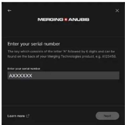
Note: Anubis does not need to be connected, but the exported serial must match the Anubis serial that will re-import the profile.
- Carefully take note of the exported SoundID profile path. Browse if you wish to change the export destination folder.

- Once having Exported the profile to your system, disable SoundID and/or close it.
- To Import the Preset Profiles in Anubis launch the Anubis remote Web Access page. From the MAD, VAD or ANEMAN double mouse click on the Anubis Icon.


Double Mouse Click
- The Web Access will open, at the top left under menu select "Upload SoundID profile" in order to import the profile into the Anubis

Monitor Mission Web Access
- The profiles have now been imported into your Anubis. To manage (rename, delete) the Profiles go to settings>SoundID Reference page

Number: The Profiles are sorted in alphabetical order
Name/Rename: Tap the profile name, to open the virtual keyboard and rename your profiles
Target: Target mode of the SoundID profile
- Flat: Flat target curve, based on neutral speakers in a treated room. SoundID SR (Studio Reference) defines the sound target for all Headphones.
- Check: Simulate specific listening environments or device
- Custom: Adjust the target curve or limit calibration to a specific frequency region • Dolby: Dolby Atmos Music (matched)
Delete: Tap the trash can icon next to the profile to delete this one.
SoundID Profiles management
How to apply a SoundID profile in the Monitor Mission.
Restrictions:
- SoundID profiles can be applied to a maximum of two Reference Corrections simultaneously (Speakers or Headphones). ■ Speakers sets, Headphones and CUES support SoundID Profiles
- If a SoundID cannot be applied the active EQ resources must be disabled from current Monitor outputs.
Go to the Anubis Settings > Monitor, under the SoundID Reference Correction, enter the Monitor set you wish to apply the SoundID profile to. Apply the SoundID profile to either Speaker set or Headphones set or both.


Enable
Activate the SoundID selected profile.

Profile
Drop down menu populated with uploaded SoundID profiles imported from the Web Access page.
Monitor Main Page Indicators.
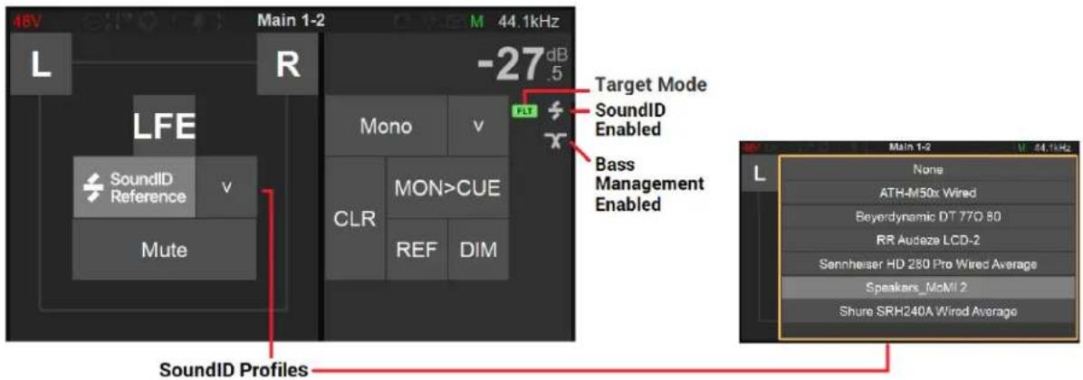
Note: Select and load a SoundID profile from the Dropdown listing. Profiles can also be applied from the Settings > Monitors.
SoundID integration latency when enabled
(as of Firmware 1.4.6 and above)
"Headphones" and "Cues" monitor bus types:
44.1kHz: 0.34ms
48kHz: 0.31ms
88.2kHz: 0.17ms
96kHz: 0.15ms
176.4kHz: 0.09ms
192kHz: 0.08ms
352.8kHz: 0.04ms
384kHz: 0.03ms
"Speakersets" monitor type:
For FPGA architectural reasons, an extra delay of 1.4ms is added to the above values in the case of speaker sets. (This is approximately equivalent to an extra 50cm of distance between the listener and the speakers.)
When a faster time of travel is required, for example for tracking in the control room on speakers, two options are available:
a.) Make sure that the SoundID Measure application reported delay between your stereo speakers is 0ms. This is achievable by ensuring the microphone is placed exactly at the same distance from the L and the R speaker when doing the measurement. When the measured delay is 0ms, Anubis will not add 1.4 ms onto your speakerset.
b.) Change the monitor type used to "Headphones" or "Cue" (see user manual for differences). This will reject any time differences between channels for the lowest possible latency.
Note: Support for 352.8kHz (DXD) and 384kHz is available as of firmware release (post 1.4.6 and above).
Remote SoundID Controls
Remote control your SoundID profiles and choose when to apply or not a correction to a given Monitor Set.
SoundID remote parameters
Profiles Selector

Crossfeed
Crossfeed only applies to Headphones. It is the process of blending the left and right channels of a stereo audio recording. It is generally used to reduce the extreme channel separation when monitoring with headphones vs. speakers (e.g., where instruments are panned entirely on one side or the other). Apply Crossfeed to make audio played through headphones sound more natural, as when listening to a pair of external speakers. Select and turn the Anubis Rotary Knob to apply. Range: 0 (no crossfeed applied) to 100% (equivalent to mono).

Talkback
It is first recommended that you configure your Talkbacks from the Settings>Talks page. Once having configured the Talkback #1 and/or #2, those settings will determine if and which Talker will be inserted into the selected Monitor Set, Headphones or Cue when engaged.
Sources Dim: When talkback is engaged all the listening sources feeding the monitor are dimmed to the value selected. Example: To Dim the DAW playback source when talking to a musician.
Talker Dim: Apply a Dim attenuation to the talkback Mic when engaged.
Example: To avoid feedback in a Studio control room when engaging the talkback while monitoring speakers and the talkback simultaneously or to allow to make a pleasant balance between Music listening and talking (without needing to change the monitor volume each time somebody is talking).
Talk A: Select a Talk source available, in order to inject this source when selected in this Cue or Monitor set Note: Talks must first be configured in the Settings>Talks.
Talk B: If you need a second talkback, select a Talk source available, in order to inject this one when engaged in this Cue or Monitor set Note: Talks must first be configured in the Settings>Talks.
Available Sources
At the bottom of the Monitor Settings, the operation can enable which existing Sources should be visible for a given Monitor Set

The Disabled Source will be hidden in the Source selection page listing

Monitor Levels
The Monitor Levels settings are in relation to the Monitor Control section of the Main pages and can be recalled from this section.

Surround Options (available as of firmware 1.5.1):
5.1 TO 7.1 MONITORING: Surround options for 5.1 with various choices of speaker layouts
Ls/Rs to Lss/Rss: Can be used if the Sides positions are set to 110 degrees
Ls/Rs to Lrs/Rrs: Default/legacy compatibility.
Ls/Rs to Lss-Lrs/Rss-Rrs: The surround 5.1 will be redistributed to the Sides and Rear speakers.
This results in a phantom speaker corresponding to the 5.1 mapping speakers placement.

Max Level:
Set the Maximum volume level boundary, use the Anubis Rotary Knob to set the value.
Range: -36dB to +12dB
Ref Level:
Determine the Reference listening level you wish to establish when recalled. Set the level by using the Rotary Knob.
Range: -36dB to +12dB
Dim Level:
Set the desired Dim level value by using the Rotary Knob. The Dim attenuation is applied to the current volume value of a Speaker Set (Dim does not apply to Headphones or Cues Monitors).
Apply the Dim from the Main Pages Monitoring controls.
Range: -60dB to 0dB
Note: Ref and Dim only apply to Speaker Set Type of Monitor Modes

TALKS Settings
The Anubis Talkback logic is not restricted to the built-in mic but is able to use any other microphone (including Phantom power condenser mics) as well. With the possibility to setup by software two Talkback or Listen mics sending out to different Speaker Set/Headphones monitors.
Talkback Circuitry![graph LR A["Analog in 1-4' 'Analog 4 or Bull-In Mic'"] --> B["Monitor Talks"] C["AES67 streams RAVENNA streams"] --> D["Sources"] B --> E["Talk"] D --> F["Dim"] E --> G["∑"] F --> G G --> H["Monitor"] H --> I["Analog out 1-4"] H --> J["Headphone 1-2"] H --> K["AES67 streams RAVENNA streams"] L["Talk…](/content/2026/07/1441624/images/2ff76bdff276d7d089e218bacc6ec5a22296af303013923270600243447de90e.jpg)
The TALKS settings have similarities to the Sources settings.

Triggers
The operator can define how the Talkback is triggered, that can be from either Anubis Talk Button or from GPI (footswitch), a trigger can engage multiple Talkbacks at a time. Refer to the GPIO Settings for more details.   Figure 7 Example: Patching the Anubis Built-in microphone and using the Anubis Talk button as the Trigger INPUTS Settings
Split channel settings. The Anubis AD front-end topology offers the split channel functionality, where every input channel has a separate split gain control for sending them to different paths. Enable the Split channel option for the Anubis Preamps channels pair of your choice. The Anubis XLR Combo 1/2 inputs or the Jack 3/4 inputs.  When enabled, within the Anubis Preamps pages a second pair of Preamps will appear for each Split Channel pair. Allowing you Split control over: Gain, Polarity and Low Cut parameters.   Global Outputs Setting Roll Off Filter: Sharp: Offers a flat frequency response with an attenuation of 3 dB at 0.484 x FS (23.2 kHz @48k), which has the tradeoff of 35 samples latency.  Slow (default): Offers the lowest latency of 9 samples, with the tradeoff of a gentle frequency response attenuation reaching -3dB at 0.45 x FS (21.6 kHz @48k)  Apodizing: Fast Roll-Off filter, Linear phase filter. Latency of 35 samples  Brickwall: Ensures rejection of more than -100dB at Nyquist (0.50 x FS, 24 kHz @48k). Latency of 35 samples  XLR 1/2: Line output level of the physical XLR outputs 1 and 2 located at the back to the Anubis Max Output Level: +18dBu or +24dBu Attenuation*: +0dBu or -36dBu Channel 1: Polarity setting Channel 2: Polarity setting  Warning: Please refer to the section on How to connect a balanced line output to an unbalanced input regarding Max Output Level limitation. JACK 3/4: Physical TRS jack outputs 3 and 4 located at the back to the Anubis Same parameters as above (XLR 1-2) HEADPHONE 1: Headphone set 1 located at the front Anubis left side Max Output Level: +9dBu or +18dBu Attenuation*: +0dBu or -36dBu Channel 1: Polarity setting Channel 2: Polarity setting HEADPHONE 2: Headphone set 2 located at the front right side of the Anubis Same parameters as above (Headphones 1). The Anubis digital to analog converters are designed to drive high or low impedance headphones at high levels with significant audio output Power undistorted. User should be attentive to the impedance of the headphones being used and set the Anubis Max Output level accordingly. Warning: It is not recommended for headphones with an impedance below 200 Ohms to select an Output Level of +18dBu. As a preventive measure, a warning message will be displayed each time a user changes the Output Level of the Headphones from +9dBu to +18dB  Warning: The Anubis Headphones output level can make your headphones very loud if it is turned up too high, and that could cause permanent hearing damage. Please be careful with your ears when using the +18dBu setting. *As of Firmware 1.0.16 and higher. The Settings>Audio Outputs page no longer have per channel output Trims. This was replaced by an Attenuation feature for the output pairs. Trim / channel have to be done in the Monitor from now on. TRIGGERS Settings
 MIDI or GPIO Selector: Switch between GPIO or MIDI (default)Users can select either MIDI or GPIO and cannot combine one with the other.  Talkback button type: Configure the behavior of the Anubis Talkback button  No Latch: Keep pressed to Talk and release to end the discussion Latch: Press to Talk and press again to end the discussion Auto-Latch (default): Auto-Latch (default): Act as No Latch if keep pressed after 333 ms otherwise act as a Latch. Note: When engage the Anubis Talkback button will be blinking Talkback button trig: Define which of the Talks will the Anubis physical Talkback button trig, either the Talk 1, the Talk 2 or both. MIDI Mode
Connect a Keyboard MIDI Out -> Anubis MIDI IN and via RAVENNA/RTP or configure your MIDI so that your Keyboard triggers DAW VST instruments. The DAW source stream is then monitored from ANUBIS. A DAW/MIDI program can as well return a MIDI out signal, that could play a MIDI partition via the MIDI Out that would be connected to the MIDI Input of an external Synthesizer.Requirements:
It is mandatory to use a MIDI Jack 1/4 with the proper pin out. Such cable is available on the Merging pricelist, refer to the closest Merging Sales partners near you for ordering.MIDI Setup procedure:
The MIDI ports will be available in your computer once the Anubis drivers are installed and once you've followed the PC or Mac procedure here. https://merging.atlassian.net/wiki/spaces/PUBLICDOC/pages/4818908GPIO Functions
The general-purpose input/output is an uncommitted digital signal pin on an integrated circuit or electronic circuit board whose behavior—including whether it acts as input or output—is controllable by the user. Typically used by example with a footswitch (GPI) that would trigger a second Talkback whom status would be reflected (GPO). Enabled the GPIO mode in order to use those I/O (located at the back of the Anubis), by doing so two new entries, GPI and GPO will appear in the Triggers Settings.  GPI: General-purpose Input and the GPO: General-purpose Output GPI Settings
Enter the GPI page in order to configure the GPI triggering function type and triggering modes.  Pulse: Action is executed when the (foot)switch moves from close to open state. State: Action is executed when the (foot)switch moves to open state. Actions in Toggle mode will reflect the state as follow: open = on, close = off State Inverted: Action is executed when the (foot)switch moves to close state. Actions in Toggle mode will reflect the state as follow: open = off, close = on  Create a new GPI action: Determine what will be the action triggered  Created actions are by default enabled, but users can disable an Action at any time   Select to delete an action Group: A fixed list of Group options are available  Component: Will vary with the Group option selected. Function: Will vary with the Component option selected. Action: Toggle: Action will toggle between ON and OFF On: Action will be turned ON (only) Off: Action will be turned OFF (only) Trig: Applies the action at every triggering  Note: In the example here above a footswitch will trigger the PreAmps Cut option On/Off in order to use this one as a cough pedal. GPI: State/Pulse table| Group | Component | Function | Action | Description |
| General | n/a | Sum | On/Off/Toggle | |
| n/a | Mon>Cue | On/Off/Toggle | ||
| n/a | Peak reset | Do | ||
| Monitor | Mute | On/Off/Toggle | Do not work if Monitor is a Speaket Set. Use Speaker set instead | |
| Downmix | On/Off/Toggle | |||
| SpeakerSet | n/a | Mute | On/Off/Toggle | |
| n/a | Dim | On/Off/Toggle | ||
| n/a | Ref | Do | ||
| Select | On/Off/Toggle | Limitation: Multiple subsequent select on a given Monitor do not work yet | ||
| Talkback | Talk | On/Off/Toggle | ||
| Preamp | Cut | On/Off/Toggle | ||
| In [1/2/3/4] | Highpass | On/Off/Toggle | ||
| Presets | Recall | Preset [1,2,3,4,5] | Do | |
| Transport | n/a | Stop/Rec | Toggle | n/a |
| n/a | Play/Stop | Toggle | n/a | |
| n/a | Punch In/Out | Toggle | n/a |
GPO Settings
Enter the GPO page to configure the GPO triggering function type, where you can select between 2 triggering modes.  On: When the Action (or the action condition) is true, the transistor is in On state. Transistor do conduct Off: When the Action (or the action condition) is true, the transistor is in Off state. Transistor do not conduct  Create a new GPO action: Determine what will be the action triggered  Created actions are by default enabled, but users can disable an Action at any time  Select to delete an action Group: A fixed list of Group options are available| General |
| Monitor |
| Speaker Set |
| Talkback |
| Preamp |
| Group | Component | Function | Action | Description |
| General | n/a | Summed | n/a | |
| n/a | Mon>Cue | n/a | ||
| n/a | Clipping | n/a | ||
| Monitor | Muted | n/a | ||
| Downmix | n/a | |||
| Sel. Speakerset | Under development | |||
| SpeakerSet | n/a | Dimed | n/a | |
| n/a | Is Ref | n/a | ||
| Talkback | Talking | n/a | ||
| Preamp | In [1/2/3/4] | Clipping | n/a | Under development |
| Transport | n/a | Recording | n/a | |
| n/a | Playing | n/a | ||
| n/a | Stopped | n/a |
Pedal switch types that can be used for GPIO
Momentary switch: Remains in its "on" state only as long as it is being compressed. Once the user removes the compression of the switch the device is no longer on. An everyday example of a momentary switch is an electric drill. Once the compression of the switch is removed the drill will stop rotating. With such a pedal Talkback could be engaged only when the pedal is pressed. Latching switch: Needs to be pressed once for ON and again for OFF, for example a light switch. Once the lights are on, the switch can be left until they need to be turned off. It applies also to the Talkback, press to engage Talkback ON and press again set Talkback OFF.ACCESS CONTROL Settings
Access Control
Apply security access to a list of parameters (items) in order to prevent some operators to have full access, you can thus limit those with a password protection. Looks are independent to the Presets to guarantee full protection at all times.Lock procedure
1. Enter the Access Control entry
2. Add a new lock
3. A new Lock entry will be added.
Lock
Name: Rename the lock if you wish (recommended for clarification) Password: Apply the password for protection, the password will be linked to the Lock entryItems
List of items that you can select and apply to the lock entry. The Items parameters listed for protection will vary with the Mission in operation and will be Mission dependent. 4. In the example here we enable a Settings lock that will require the password 1234  Note: The first of the Settings entry listed is the Main Settings (root) page entry. 5. In case of a wrong password entered the user access to those Settings will be denied. Enter password (1234 in the example here)  6. This will open the Settings page Delete Lock. At all times a user can delete Lock entry to remove it.  To reinitialize the applied Locks. 1. Save the current Preset 2. Open the Anubis Settings 3. Go to the Exit page 4. Select Reboot to factory Warning: This will reinitialize all the applied Locks Settings.INFO Settings
Info
Find all information about the Anubis Name, Type, Firmware version, Maintenance mode and Serial Number along with additional information on the Anubis status: Temperature, CPU and Memory usage.| < Settings Info | |
| Device's name | Anubis_Premium |
| Type | Premium |
| Firmware version | 1.0.0b28910 |
| Maintenance Mode version | 16 |
| Serial Number | A650041 |
| Boards run | Main: 3 Front: 3 UI: 3 |
| STATUS | |
| Temperature | 26 °C |
| Cores | 0 % 37 % |
| Memory | 10 % |
DEBUG Settings
Debug
Loopback: Internal module with Generator (Supporting 1FS) and transparency check tool (Supported up to 384kHz). Under Development.  Enabling the Loopback will provide access to the Loopback module within the Anubis I/O's. Note: The Loopback is for the moment only available as a debugging tool for the Merging Team.EXIT Settings
 Reboot
 the Anubis Note: To turn OFF Anubis, press on the POWER button to switch it to the released state. Save
Save the current Anubis configuration Note: The Anubis entire configuration is saved every 2 minutes, and as well every time you exit the Anubis Settings. If changes are applied when in the Anubis Settings and you plan to power off the Anubis while in the Settings, it is recommended to first perform a Save configuration. Reboot to Factory
Reboot your Anubis to factory settings will recall to the default factory settings.  Warning: All Sources, Monitors and Settings will be lost. Since the saved Presets will not be erased we recommend that you first back up your Anubis Configuration by saving it to a Preset.ANUBIS MONITOR MISSION CONTROL
The Monitor Mission is designed for professional applications where superior monitoring capabilities are truly mission critical. No matter how large your studio is, monitoring matters. State of the art features that are the standard of today have been carefully integrated, while unique and future proof capabilities were specifically added to the feature set to meet the challenges of tomorrow. The Anubis Monitor Mission allows you to be in complete control of your monitoring; reference monitors, near-field monitors, headphones, sources, surround mix, downmix, etc. The Monitor Mission is the central node of essentially any Music, Recording and Broadcast Studio. It's extreme sound quality fulfills the essential requirement of all Mastering Studios. The large number of supported surround formats will please all Film and TV Post Studios and its AoIP standards support makes it the perfect choice for Broadcast Studios, OB Vans or Editing Rooms. The Anubis compactness and robustness makes it the ideal choice for Location Recording and Live Events monitoring. PCM 44.1 kHz to 384 kHz  DSD 64 to 256  Monitor Mission Engine   Bypassing the Anubis Monitoring Engine will prevent control over Volume (Rotary), Trim, Mute and more. Such connection could be desired for direct IO use and for connecting for example, an A/D directly to a D/A for Effect Inserts usage. For Monitoring Control purposes this is it not recommended.  Signal path going through the Monitoring Mix Engine, for Monitoring control over the entire Anubis Monitoring feature set, with the use of Sources and Monitors.  Figure 8 Bypassing Monitoring Engine  Figure 9 Properly Routed for Monitoring Mission Missions IO Channels Specifications| Max channels for | 44.1/48 kHz | 88.2/96 kHz | 176.4/192 kHz | 352.8/384 kHz | DXD | DSD64 | DSD128 | DSD256 |
| Anubis incoming streams | 64 | 64 | 64 | 64 | 64 | 64 | 64 | 64 |
| Anubis outgoing streams* | 64 | 64 | 64 | 64 | 64 | 64 | 64 | 64 |
| *count may vary depending of ASIO clock status | ||||||||
| Anubis incoming channels streams | 256 | 256 | 128 | 48 | 48 | 64 | 64 | 64 |
| Anubis outgoing channels streams | 256 | 256 | 128 | 64 | 64 | 64 | 64 | 64 |
| Anubis+Monitor Sources | 128 | 128 | 64 | 32 | 32 | 32 | 32 | 32 |
| Anubis+Monitor Monitors | 32 | 32 | 32 | 32 | 32 | 32 | 32 | 32 |
| Anubis+Music Input Mixer | 48 | 48 | 48 | 24 | 24 | N/A | N/A | N/A |
| Anubis+Music Output Mixer | 24 | 24 | 24 | 24 | 24 | N/A | N/A | N/A |
Sources vs. Monitors Fundamentals
It is fundamental with the Anubis Monitoring Mission to understand the importance of using Sources (Mixer inputs) and Monitors (Mixer outputs), as this is the base of the Anubis Monitoring Engine. Not doing so will bypass the Monitoring engine and prevent proper Monitor Control (Volume control, Mute, Trim...).  Different types of Sources and Monitors going through the Monitor Engine Different Monitor types
The Anubis Monitor Mission provides the operator with control over three types of Monitors. Anubis can host up to 8 Monitors, capable of up to 22.2 (maximum 32 channels).1. Speaker Set
Recommended to be used for Speaker Sets (e.g. Reference Monitors).2. Headphones
Recommended to be used for Headphones Sets monitoring.3. Cue
Recommended to be used when a specific mix of Sources is needed for a chosen Monitor set or when recording to produce a low-latency Cue mix for the performer foldback. Note: Each of the three types of Anubis Monitors have their unique set of features and possibilities. Refer to the table below for more details. Monitors Types and Features table| ANUBIS MONITOR TYPES | |||
| Features | Speaker set | Headphone | Cue |
| Channel Controls - Solo/Mute/Polarity | X | ||
| Adaptive Downmix | X | X | X |
| Manual Downmix | X | X | X |
| Surround / Immersive | X | X | |
| Crossfeed | X | ||
| Bass management | X | ||
| Mute (independent) | X | X | X |
| Volume (independent) | X | X | X |
| Ref | X | ||
| Dim | X | ||
| Max level | X | ||
| Independent Source selection | X | ||
| Share Source selection | X | X | |
| Apply source sel. to Cues (Mon>Cue) | X | ||
| Colored indicator | X | X | |
| Shared Outputs | X | ||
| Multi-instance (running concurrently) | X | X | |
| Source availability within a Monitor | X | X | X |
| SoundID Reference Support | X | X | X |
| ANUBIS SOURCES TYPES | ||
| Features | Discrete | Stream listener |
| Channel mapping | Fixed choices | Freely configurable |
| Physical inputs | Patchable | N/A |
| AoIP streams | Patchable | Can be selected from the Source page |
| AoIP streams status | N/A | Shown in the Source page |
| AoIP stream filtering | N/A | Configurable via wildcards |
| AoIP Source discovering | No | Yes |
| ANEMAN required | Yes | No |
| When use it | ||
| Need to monitor physical input | X | |
| Need to monitor many streams | X | |
| 1 Click selection | X | |
| Limited summation resources (DXD) | X | |
| Stream status | X | |
| ANUBIS SOURCES AND MONITORS MAX CHANNELS | ||
| Sources | Monitors | |
| 1 Fs (44.1-48 kHz) | 128 | 32 |
| 2 Fs (88.2-96 kHz) | 128 | 32 |
| 4 Fs (176.4-192 kHz) | 64 | 32 |
| 8 Fs (352.8-384 kHz) | 32 | 32 |
MAIN PAGES - MONITOR MISSION
The Monitor mission has 3 main pages, press the Anubis home button to cycle between those. Monitor Page  Source page Meters page
 Single tap on the Anubis Home button to cycle between the three MONITOR Pages. At all times return to the Anubis Home page (Settings/Preamps) by a long press on the Anubis Home button. MONITOR PAGE
The monitor page is the mother of the Monitoring pages, allowing you to select the fundamental functions of your monitoring setup. A Monitor set will only appear once created in the Anubis Settings, properly configured and assigned to a specific button (hardware key or softkey). Refer to the Settings Sources and Monitors section for all details. Your speaker set will come into display once you select the key that it is assigned to. By default, Anubis comes with some predefined Monitor sets that can be used right away, those can be reconfigured or deleted as one wishes. Speakers Set Controls (left section)
Get full control over your monitoring setup by having control over your Speakers. Each Speaker of a Monitoring Set is represented by a button given the name of the speaker channel type. Typically, L (left) and R (right) for a Stereo Monitor Set. Multichannel Immersive sets with 3D elevation will be represented in layers. Access to each of the level layers by using the; Mid, Top and Bottom layer view options.  Mid Layer  Top Layer  Bottom Layer  Tap the Speaker control box to open the dialog, for Speaker controls such as: Mute, Solo, SoloX and Phase option controls. Those functions can be applied to the Speaker(s) of your choice. Mute: Mute function available for each speaker in your set. Tap a speaker to cut its signal.  Figure 10 Example: Muting LFE Solo: Solos the Speaker by muting all other speakers. Available for each speaker in your set up.  Figure 11 Example: Solo L and R channels SoloX: Exclusive Solo function available for each speaker in your set up. Tap the speaker you wish to Solo exclusively, this will un-solo speakers that were previously soloed.  Figure 12 Example: Exclusive Solo of Left Surround Polarity: Invert the polarity of a chosen speaker in your set up. Tap a speaker to invert its polarity, this can be useful to check or fix phase cancellation problems. The polarity is a latching function that can be applied in addition to Mute/Solo or SoloX options.  Figure 13 Example: Polarity applied to L and R speaker channels Clear: Use the Clear function to re-initialize the Speaker controls, this will remove all applied controls to the speakers. Monitor Controls (right section)
Volume Level
The top right section of the Monitor Controls section indicates the level of the currently selected Monitor set. Note: All Speaker sets share the same global level (unless Trim applied) while Headphones and Cues have each their own independent level. To have different levels on your Speaker Set Monitors it is recommended to apply a Trim on any of the Monitor Set. Hold
The Hold option will lock the volume control when enabled to avoid level calibration and reference changes. Downmix
The Downmix possibilities are available within the dropdown menu and allow the operator to Downmix to a subset of the Speaker Set. The available possibilities depend on the Speaker set configuration. Please refer to the Downmix Table on the next page for the available downmix listing. Note #1: Each Speaker Set have their own Downmix selection (as of Firmware 1.0.10 and above) Note #2: For surround 5.1 Downmix refer to the Surround Options under Settings>Monitor LevelMON>CUE
Mon > Cue Allows the operator to override the Cue Mix by sending the Speaker Set directly to the Cue listener. Only Speaker Set Monitor types can override cues. To prevent a Cue monitor set from being overridden, enable the inactive option under Settings>Monitors of the selected Cue.REF
Ref
Select to recall your reference level, the default Reference level is set to -20 dB and can be configured from the Anubis Settings>Monitor Levels.DIM
Dim
Turns the Main Monitor output dimmer on, the default Dim level is set to -20 dB and can be configured from the Anubis Settings>Monitor Levels.CLR
Clear
Using the Clear function will reinitialize all parameters that were applied to the selected Speaker Control Section and removes all applied controls to speakers.1 3 4
SoftKeys
A total of 4 Softkeys are available and can be used to control extra Monitor Sets, Cues or Headphones. The SoftKeys mapping must first be configured from the Anubis Settings>Monitors under the Monitor Set settings. Tap a Softkey to activate its Monitoring just as you would with a Hardware button, giving you flexibility of local or network Web Access remote control.Downmix Table
Monitor Channels - Types vs. Downmix formats available.| Mono | 1.1 | Stereo | 2.1 | 2.2 | Stereo Srnd | 3.0 LCR | 3.0 Srnd | 3.1 Srnd | 4.0 Quadro | 4.1 Quadro | 4.5 Srnd | 4.1 Srnd | 5.0 LCR | 5.1 LCR | 5.2 LRC | 5.0 ITU-B | 5.1 ITU-B | 6.0 LCR | 6.1 LCR | 6.2 LRC | 7.0 LCR | 7.1 LCR | 7.0 ITU-I | 7.1 ITU-I | 7.0 SDDS | 7.1 SDDS | 7.0 ITU-C | 7.1 ITU-C | 8.0 LCR | 8.1 LCR | 9.0 LCR | 9.1 LCR | 9.0 ITU-D | 9.1 ITU-E | 11.0 | 11.1 | Dolby 5.0 | Dolby 5.1 | Dolby 7.0 | Dolby 7.1 | Dolby 9.1 | Dolby 5.1.2 | Dolby 5.1.4 | Dolby 7.1.2 | Dolby 7.1.4 | Dolby 7.1.6 | Dolby 9.1.2 | Dolby 9.1.4 | Dolby 9.1.6 | Sony RA 13.0 | Sony RA 35.0 | 10.2 TMH | 12.2 TMH | Auro 8.0 | Auro 9.1 | Auro 10.1 | Auro 7.4 | Auro 11.1 | Auro 13.1 | 10.2 ITU-F | 7/2/2004 | 22.2 ITU-H | Cube | Cube Mid | Cube C/F | Cube C/F/E | 30.2 | |||||||||||||||||||||||||||||||||
| Mono | ||||||||||||||||||||||||||||||||||||||||||||||||||||||||||||||||||||||||||||||||||||||||||||||||||||
| 1.1 | ||||||||||||||||||||||||||||||||||||||||||||||||||||||||||||||||||||||||||||||||||||||||||||||||||||
| Stereo | ||||||||||||||||||||||||||||||||||||||||||||||||||||||||||||||||||||||||||||||||||||||||||||||||||||
SOURCE PAGE
The Source page allows the operator to select the different Sources he wishes to monitor. You can exclusively select a Source or sum multiple Sources and as well apply level Trim. The Sources page also gives you Monitor Controls, with similarities to the Monitor page. Source Type
This first section on the left indicates the Source Type name as well as the Metering of the Source, once this one has been configured and patched form the Settings>Sources. Note: The meters peak level displays the max of all corresponding channels.Source Monitor codec status icons.
? Codec is unknown Source has no stream or is not patched DSD A DSD Patched or Streamed signal is detected # Channel codec mismatch (E.g. L channel receives DSD64 and R channel is receives DSD256)There are two types of Sources.
1. Standard Sources: Full control over Channel type and Speaker set, with a dedicated Source entry. The source must be created and routed from the settings or from ANEMAN. 2. AoIP/Stream listeners: Used to monitor streams available over a RAVENNA/AES67 network. Those must be created from the Settings>Sources and will then appear in the main Sources page. Available Streams are listed in the AoIP dialog once tapping in the AoIP selection area. From the dialog choose the AoIP/Stream source you wish to Monitor. Note: The AoIP Streams up 2/8/16 channels with customization of the channels type (as of Firmware 1.4.4 and above).   AoIP STREAMS MONITORING  AoIP STREAM SELECTIONAoIP streams icons status
AoIP disconnected AoIP partially connected AoIP connection error AoIP RTP Error AoIP receivingAolP
Stream listener Wildcard FilteringSource Name/Selector
Name of the Source and selector. Tap the source you wish to monitor, this one will be highlighted when active, to select multiple Sources make sure you enable the SUM option, otherwise the selection is exclusive. Note: Predefined Names are available under the Sources configuration SettingsTrim
Source Trims are applied to all monitors and can be adjusted by holding the finger on the Source name while turning the Anubis Rotary knob. Turn the Rotary clockwise to increase a Trim value and turn the Rotary counter-clockwise to decrease a Trim value. Note: The Trim value is displayed in orange during adjustments.Monitors Controls
HOLD
Hold The Hold option will lock the volume control when enabled to avoid level calibration and reference changes.SUM
Sum: Enable the Sum option to select multiples Sources and sum them together into your Monitor set. When disabled the Source section is exclusive.PEAK
Peak Tapping the Peak Reset (PK) will reset the Meters PeaksMON>CUE
Mon > Cue Allows the operator to override the Cue Mix by sending the Monitor Set directly to the Cue listener. Only Speaker Set Monitor types can override cues. To prevent a Cue monitor set from being overridden, enable the inactive option under Settings>Monitors of the selected Cue.REF
Ref Select to recall your reference level, the default Reference level is set to -20 dB and can be configured from the Anubis Settings>Monitor LevelDIM
Dim Turns the selected Speaker Set output dimmer ON, the default Dim level is set to -20 dB and can be configured from the Anubis Settings>Monitor LevelMETERS PAGE
The Meters page provides an overview of the Sources and Monitors metering, along with some controls over the Sources and Monitors. Sources Meters
Metering overview of all the Sources, each source with full details of peak-meters and type per channel. The Meters display grayscale can be customized from the Settings>Meters page. Note: If the Sources content extends the current display zone, a horizontal scroll bar will be available, allowing the view of additional Sources and Meters to the right. The same applies to the Monitors Meters section. Level/Scale
At the bottom of the dB level scale find the SUM and PK functions.  Sum Enable the Sum option to select and sum multiple Sources. When disabled the source section will be exclusive. PK
Tapping the Peak Reset (PK) will reset the Meters Peaks. By default, the Peak hold is enabled. Permanent Peak hold can be disabled under the Anubis>Settings>Meters page.Trim
Trim the level of a Source or Monitor by first selecting it, while holding the meter region pressed, adjust the trim by turning the Anubis Rotary knob. Turn the Rotary clockwise to increase the Trim value and turn the Rotary counterclockwise to decrease the Trim value. Range -12dB to 0dB Note: The trim level value will be displayed in yellow when adjusted.Channel Type
Each of the Source displays the listing of their channel type abbreviation. Note: Unpatched channels will be displayed in RedSource Selection
 The Source selection section allows the operator to select which one he wants to monitor. When the Sum function is enabled multiple Sources can be summed together. Monitors Meters
The Monitors Metering are located to the right side of the Meters page. Monitors can only be selected for Trims. ANUBIS PREMIUM DXD-DSD GUIDELINES
About DXD and DSD. Anubis Premium offers the users sampling rates from 1FS up to 4FS along with support for 352.8kHz (DXD), 384kHz, DSD64, DSD128 and DSD256.  Important: DSD is supported as of Firmware 1.0.16 and higher. Bit-Perfect DSD & DXD. In DSD the file is retained in the original DSD format and directly converted to analogue without any unnecessary digital processing or decimation. MERGING+ANUBIS brings its auditors the fidelity of an extremely pure natural sound. SIGNAL FLOW DSD (DSD64, DSD128, DSD256) DSD Features & Restrictions:
DSD Features:
- DSD Input and Output Support - Volume control on all Outputs including the two Anubis Heaphones sets - Delay support on Monitors - Trim Support on Monitors - Attenuation Support on all Outputs - Polarity support on all Outputs - Reference and Dim level support - Input metering with SACD headroom scale (+6dB SA-CD) - Speaker set, Headphones and Cue types monitors supported - Speaker Set control page (Mute, Solo, SoloX, Polarity) DSD Restrictions: What is unavailable when the Anubis is in DSD. Those restriction do not apply to DXD. - Multi-Source selection (SUM) * - Bass management - Downmix - Crossfeed - No Sources Trim support (Trim monitors is however available) - No Metering on DSD RAVENNA sources - No Output Metering in DSD - Max Volume level is 0dB ** - Talkback (currently not supported) *** - Warning switching between DXD and DSD Sources produces very short mutes in DAC. Mixed DSD and DXD source are not recommended in Recording setup * Today's firmware releases do not have DSD mixing support. Selection of sources is exclusive (no summing) ** Volume control in DXD and DSD is done on the DAC itself and will have a maximum level of 0dB. *** Talkback disabled for the Monitors. Merging plan to address those in a future release.DSD MONITORING:
Since summing not supported in DSD modes, the Source selection will be exclusive. No SUM consequences
Sum mode is no more global but becomes a property of monitors (Headphone, Cues and Speaker Set do not share the same property). Selecting a DSD Source, will set the Sum mode off. If you try to engage the Sum mode when a DSD source is selected, the log will report the following info: The selected Source cannot be summed with another one. This can happen when the Source Audio data format is e.g. DSD. Cannot simultaneously Monitor DSD and DXD sources Monitoring is exclusive to the highest sampling rate in use. Applicative example: If a user Monitors a DSD source from a Cue, this one will not be able to simultaneously Monitor another Source PCM (DXD) from another Monitor set. The consequence will be an automatic Source Deselection with warning log indication. Therefore, in order to monitor this one, the operator will have to unselect the DSD Source and select the DXD source. Mixed DSD and DXD source are not recommended in Recording setup. Note: This will not be an issue if the Monitoring is streamed to another Device. Refer to the Anubis Log Appendix for all complete message listing.DXD/DSD Volume control (DAC)
When running on those two formats the Anubis volume control will be done directly by the DAC (Digital Analog Converter) itself. The Anubis built-in Mixer cannot host and mix DSD 1Bit content today like it is done for all other PCM formats, so when in 192kHz and lower sampling rates we are controlling the Volume via Anubis DSP engine (internal mixer).Monitors Trims in DXD/DSD
 While users will see 0.1dB Steps in the Monitor Trim, the effective steps will actually be of 0.5dB /steps. This is due to the Anubis DAC specifications.Patch: Multiple target in DXD/DSD
When a Monitor channel is patched to multiple outputs/targets and if the DAC volume control is applied on one of the targets (XLR 1-2) other targets (Stream 1-2) will not have volume control. ANUBIS PREMIUM GENERAL SETTINGS
Sampling Rate
In order for ANUBIS Premium users to work in either DXD or DSD the operator must set the sampling rate to DXD/DSD.  A/D Mode in DXD/DSD:
This format setup only applies to the AD (PreAmps) which can be set to either DXD - DSD64 - DSD128 - DSD256  The Anubis can be configured in DXD/DSD, in this mode the Anubis can receive any audio data format stream and can generate DXD or DSD64, DSD128 or DSD256 stream depending on the A/D or Stream audio data format chosen. It is recommended to set the A/D mode to the same sampling rate as selected for your project. However DAW's such as Pyramid can record in a DXD project with the A/D mode set to DSD formats, this feature is only available for MassCore users (not supported in Native/ASIO) and can be quite resource demanding for high channel counts.DSD PreAmps
The Anubis Premium has been designed in order to be able to benefit from the +3.1 dB SACD headroom offered by DSD, as per the scarlet book standard. This is made possible thanks to the gain applied in the digital section post AD just prior to the sigma delta 1-bit modulator. The gain can be adjusted between +0dB and +66dB in DSD mode. In Line mode, with a gain of +6dB, an input of +21dB will generate a signal of +3dB SACD, in Mic mode, with the same gain, an input of +9dB would generate a signal of +3dB SACD. To benefit also from this +6dB headroom in DSD on the DA outputs, we recommend our users to set the Output Attenuation to -6dB on each DA module configuration page. Reference: 0dBFS (PCM) = 0dB SACD (DSD)DXD/DSD METERS
HOT DXD/DSD METERS SETTINGS
 Applies to Anubis Premium only, so effective from 352.8kHz and upwards. Hot (PCM) Level Range: -2dB to +0dB Hot (DXD/DSD) Level Range: -2dB to +6dB SACD Default setting: +2.8dB SACD Reminder: DSD users benefit from a +6dB headroom in DSD with distortion starting slightly and progressively from 3.1dB upwards and clipping once reaching +6dB SACD.DXD/DSD PEAK METERS
Anubis Meters displayed scale will be different when the Anubis Sampling Rate is set in 1FS to 4FS versus DXD or DSD this is in order to indicate the additional headroom offered by DSD. PreAmps Page View  Web Access view    1. PreAmps Input Metering scale from 44.1khz to 192kHz 2. PreAmps Input Metering scale changes when in DXD and DSD mode, in order to represent the headroom offered by DSD, as the Scarlet Book allows up to 3.1dB SACD as Max. level. Note: Input Gain level indication in dB New Meters layout as of firmware 1.5.1 Anubis Meters Page:
While the Main Meters page offers the same scales. Warning: it is important to be aware that no Outputs Meters will be available when listening to a DSD source.  Note: There will also not be Metering on DSD RAVENNA Sources, but there will be metering for the physical inputs (PreAmps)ANUBIS SPS
 The Anubis SPS (Seamless Protection Switching) version features two (2) RJ45 connectors, for ST2022-7 support (network redundancy) or to use in Switch mode. The top port can be used to power the Anubis via PoE.ANUBIS SPS ST2022-7 MODE
Seamless Protection Switching for ST2022-7 compliance.  An option available to operate the Anubis in either ST2022-7 or Switch mode  Settings>Info page SPS identification  To enable the Enable the ST2022-7 mode, go to Settings>General in the network section tap the ST2022-7 mode.  A reboot of Anubis will be required afterwards. When returning to the Settings>General two network interfaces will be available for your ST2-2207 configurationST2022-7 Remote control:
First Ethernet Port Web Server is available on port 80 (i.e. 192.168.1.107:80) Second First Ethernet Web Server is available on port 81 (i.e. 169.254.1.2:81) Refer to the link below for more details on ST2022-7 configuration setup. https://merging.atlassian.net/wiki/spaces/PUBLICDOC/pages/4819584/Merging+RAVENNA+ASI O+Merging+Audio+Device+ST2022-7+Setup. Note: The ST2022-7 mode can also be used if you want to access Anubis from two different networks. In example operate Anubis on your RAVENNA Network and at the same time remote control Anubis from another network, such as your home network with WIFI and access point.ANUBIS SPS SWITCH MODE (factory default)
The SPS Model can be set to network switch mode, allowing the daisy-chaining of one additional network device without the need for an external network switch. In scenarios where a DAW simply needs to be connected to a Horus and an Anubis, i.e. when doing a mobile recording.  At manufacturing the Anubis SPS and delivered in Switch Mode, meaning that ST 2022-7 option is disabled.  Under the network settings only one Network interface will be visible. You can connect to your second Anubis Ethernet port another RAVENNA/AES67 interface such as Horus, Hapi or another Anubis. Those will then be visible in ANEMAN and immediately can be used along Anubis. Anubis SPS - Switch SetUp Use Case https://merging.atlassian.net/wiki/spaces/PUBLICDOC/pages/4818957Anubis SPS Web Access control from your phone
SetUp:
Connect your Anubis SPS to your Home network and control it from your Phone or Tablet, while at the same time have Anubis running with your DAW or system application in RAVENNA. It is highly recommended to use a Kiosk app (ideal is the Kiosk Pro and the Pro-Lite is free)Procedure:
1. For this specific workflow since we are here on two different networks (RAVENNA & Home) the Anubis must be set to ST2022-7 mode. Go to the Anubis General settings and enable ST2022-7.  A reboot is required. 2- Connect your home network to the top port of the Anubis SPS (port #1) 3- Connect your RAVENNA Network to the bottom port of the Anubis SPS (port #2) 4- Go to the Anubis General Settings and scroll to the Network configurations. 5- The Network 1 should be your home network, so Anubis IP address and subnet mask must be in the proper range of your home network (example 169.254.1.107 subnet mark 255.255.255.0), Go to manual mode if you need to edit those. 6- The Network 2 is your RAVENNA network and should be in the IP address and subnet mask range of your RAVENNA network. (example 192.168.1.2 subnet mark 255.255.0.0) Go to manual mode if you need to edit those.Example
 7- Press Apply & Reboot after changing the network configuration. If your PC or Mac is also connected to the home network, open the MT Discovery utility installed along Merging's applications. You will then see the Anubis discovered twice once on your Home Network and Once from your RAVENNA network.Remote control:
First Ethernet Port Web Server is available on port 80 (i.e. 169.254.1.107:80) Second First Ethernet Web Server is available on port 81 (i.e. 192.168.1.2:81)  You can operate the Anubis in RAVENNA mode (169.254.1.2) and make your RAVENNA stream connections with to the MassCore or RAVENNA ASIO. To open the Web Access on your Phone or Tablet by typing the Network 1 Anubis IP address followed by :80. example 192.168.1.107:80 PEERING
 The Peering allows the Anubis to discover Hapi, Horus or another Anubis given that they are on the same network. From within the peering page, a user can select the I/O module to be used (AD's, AES, MADI, ADAT...). The Anubis is then immediately extended and has more I/O available that can be input (sources), mixed (sum), outputted (monitors) all those can then be controlled by Anubis, exactly as if they were internal I/Os. Note: Peering does not require a computer system (PC/Mac) to be defined, it can be performed with two standalone devices. Peering is available from the Anubis Home menu  Peering Example  Setup example: Merging Hapi has been peered in Anubis, so that the Hapi AD Module (PreAmps Mics) are mixed within the Anubis ultra-low latency engine, thus for the performers' Cues. Additional peered outputs can be used for Multichannel monitoring. Application Example: Anubis is peered with a Hapi that is setup with 8 Mics on musicians, those 8 Inputs are within Sources, and can be SUM in a Cue, to benefit from the Anubis ultra-low latency Mixer. Those peered channels (Source) can be adjusted to a desired level and SUM with other Input Sources that could be Anubis direct inputs. Peer Outputs to expand your Monitors outputs channels (e.g. Hapi DA outs for Dolby Atmos monitoring). Patch the peered outputs in a new Monitor and control all those outputs from within the Anubis Monitor Mission.Peer to Expand the Anubis I/O
Quick way to easily increase the Anubis I/O without having to use external system (PC or MAC) and applications such as ANEMAN. As long as those devices are from Merging and given that they are on the same RAVENNA network, you will be able to discover and peer those devices modules from Anubis. Peer to SUM (Mix) the Sources (+ Inputs) or send to Monitors (+ Output) for re-distribution The ultra-low latency Cue mixes will require Peering so that inputs from another device can be mixed within Anubis with ease. Once you have peered an input module from another device, this one will appear in the Anubis Mixer view > Source/Monitor Patch, where you will be able to mix those inputs within the Anubis and be able to route them to the outputs of your choice, either local to Anubis or back to the output of the device, in this case a peered output module has to be enabled.Peer for Remote Control PreAmps
Once an AD module from another device is peered from an Anubis, the PreAmps page of the Anubis is extended to that device's additional inputs, allowing remote control of a peered device AD module from within the Anubis TFT PreAmps page.  (Refer to the User Manual PreAmps section for details on the PreAmps page.)How to peer a device
Requirements: ■ Have more than one Merging device such as a Horus, Hapi or Anubis ■ The Horus and Hapi must be on firmware 3.10.0 and above. ■ Anubis must be on Firmware 1.2.2. and above \- Make sure that those devices are connected to the same RAVENNA network as Anubis or have one of those connected directly to one of the Anubis SPS port (if you have that model) \- Warning: Peering Multiple Anubis is possible but might involve a different procedure. (Please refer to the "Multiple Anubis Peering" section) 1. Connect another Merging RAVENNA device your Anubis network 2. Under the Anubis Home tap to open the Peering page.  3. The online devices should be discovered on the left column under Devices.  4. Select the device you want to peer (Horus in the example here) make sure this one is online so on the same RAVENNA network as your Anubis.  Online  Offline (not available for peering) 5. Once selected, it will open the Device Modules and I/O's available for peering. Devices such as Horus have more I/O available that can be seen by scrolling down the page.    6. Select a module and the I/O's you wish to peer with Anubis. This will open a dialog from which, depending on the module I/O's available, you can choose between 1, 4 or 8 channels.  Note: For example we will peer the ADA 8 Preamps inputs 1-8 and the outputs channels 1-8  7. once peered the indicators should be green.  Note: A peered AD Module will indicate the PreAmps MIDI Pre Channel start number [15] the example below the Remote PreAmps will start as of preamps #5 for the A/D1 peered module  8. Exit the peering page from the Anubis Home button.  9. In the Monitor Mission the peered IO's will appear respectively in the Source and Monitor Patched channels. Peered Inputs example under Settings>Sources>Channels>Patch  Peered Inputs Typical usage: create a new Source and connect the Peered inputs to that new Source and monitor this new source from Anubis. 10. The Peered AD modules will appear in the Anubis PreAmps page following the local Anubis PreAmps. Swipe from left to the right in the PreAmps page to access the peered PreAmps.   Note: Peered modules PreAmps from devices that are not an Anubis might not support some parameters (Cut, Lock, Boost) 10. Your Peered output channels will be available in the Monitors Patch settings, Peered outputs example under Settings>Monitors>Channels>Patch  Peered Outputs Typical usage: create a new Monitor set and connect the Peered outputs to that new Monitor, from within Anubis you can now Monitor Multichannel content that will come out from the physicals outputs of the peered Output module. 11. Use ANEMAN in order to establish the Inputs our Outputs streams connections for record back or outputs within the DAW. Your Anubis has now been extended to use those extra I/O's that are now available within the Anubis Mix engine and Bus Routing. Refer to the Bus Routing section for more details.Peering Rules & Behavior
■ Peering can only be performed from an Anubis and requires Merging RAVENNA devices ■ 64 peered inputs officially supported (8 different modules of 1 to 8 channels each) - Monitor Mission: 256 I/Os and Music Mission 48 I/Os are within one Anubis up to 4FS (192kHz), 24 I/Os in DXD 352.8 or 384kHz which includes the Anubis local inputs. ■ Anubis controls the frame size (latency) and sampling rate of the peered devices - An output module can only be peered by one device. If another device peer's the same output module it will disconnect the previous one. Last peering output module takes over ■ A second Anubis can peer an input module that is already peered by another Anubis ■ Peering is performed in Unicast, for Multicast support please use ANEMAN - Offline devices' modules cannot be peered, then can only be un-peered. - Peering does not require a system (PC/Mac) it can be performed with two standalone Merging RAVENNA/AES67 devices. ■ Peering offers the possibility to connect the same outputs to different speaker sets.ANUBIS USE CASES (MULTIPLE CASES ARE ONLINE)
https://merging.atlassian.net/wiki/spaces/PUBLICDOC/pages/4818957BASIC MONITORING SETUP
SetUp:
Using a Main Speaker Set and headphones in order to Monitor the DAW Main playout Source.Prerequisites:
First follow the User Manual section on the Drivers Installation Procedure (Drivers Installation Procedure) and ensure that you have correctly connected and powered up your Anubis. Connect your Active Monitors (or Power Amp) to the Anubis physical Outputs XLR 1 and 2 and/or TRS outputs 3-4 if you have alternate Monitors in your setup.Procedure:
1. In order to connect your DAW playback to Anubis you must first have a Source available to host your DAW Playout Stream 1-2 (if stereo) Note: Ex-factory Anubis comes with a DAW 1-2 Source. If this one is not available in the Sources page, create it, refer to the Settings>Sources manual section. 2. Launch your DAW making sure it is loading Merging's Driver (or MassCore for Pyramid users) 3. open ANEMAN and connect the RAVENNA ASIO Driver or Merging Audio Device (MAD) Output 1-2 (or VAD Outs 1-2) to the DAW Source 1-2. Users can choose and apply either a Multicast or a Unicast connection. Unicast: from one source to one destination i.e. One-to-One Multicast: from one source to multiple destinations stating an interest in receiving the traffic i.e. One-to-ManyANEMAN DAW 1-2 Source connection
(Open the Matrix view and select both Anubis and the Driver to establish a connection)  Note: If the connection is not successful, make sure that both your Anubis and Driver are at the Same Sampling Rate and Latency Frame mode or on the same multiple set (e.g. AES67-48 samples) or Driver Panel Low Latency 128 and on the Anubis Low latency 64. Mac OS users will only see the connections properly established once the DAW playback is engaged. 4. Patch your Monitor Set. Ex- Factory Speaker Sets: A, B, and Headphones 1, 2 should already be patched to their respective physical outputs. This can be verified and changed if desired under the Settings>Monitors Patch section. Default Patching under the respective Sources and Monitors settings Settings>Sources DAW 1-2 Patch Settings>Monitor Main 1-2 Speaker A Patch   Note: Settings>Monitor Line 3-4 Speaker B should be patched to Patch to Jack 3/4_3 and Jack 3/4_4| ANUBIS DEFAULT MONITORS OUTPUT PATCH | |||||||
| Monitor (type) / Outputs | Channels | XLR/Combo 1 | XLR/Combo 2 | TRS/Jack 3 | TRS/Jack 4 | Headphones 1 | Headphones 2 |
| MAIN 1-2 Speaker Set A (Stereo) | Left Channel | X | |||||
| Right Channel | X | ||||||
| LINE 3-4 Speaker Set B (Stereo) | Left Channel | X | |||||
| Right Channel | X | ||||||
| Headphones 1 (Stereo) | L-R | X | |||||
| Headphones 2 (Stereo) | L-R | X | |||||
RECORDING SETUP
Setup:
Adding Microphones and Instruments for recording while monitoring your DAW Main outputs along with an ultra-low monitoring Cue routed to the Headphones 1.Prerequisites:
Make sure you have first followed the User Manual section on the Drivers Installation and have correctly connected and powered up your Anubis. Connect your microphones to the XLR combo inputs 1-2 located at the back of the Anubis, your Guitar or Bass can be directly connected to the Hi-Z instrument input at the front Input 3. Stereo inputs 3-4 can be used, but in this case under Settings>Sources>Inst/Line the source mode has to be changed to Stereo mode, and patched to Jack 3 and Jack 4. Note: Using Input 4 will override the built-in Talkback microphone as both share the same circuitry.Procedure:
1. Your DAW playback and Monitoring should already be setup and wired, as detailed in the previous monitoring use case. 2. In order to monitor your Microphones and Instrument input, the operator can use the already available default sources. The Anubis default factory settings come with a MIC/Line 1-2 Source and Inst/Line 3 Source. If those sources are not available or if you wish to use different sources, please refer to the Settings>Sources manual section. Anubis factory default Sources patching| ANUBIS DEFAULT SOURCES INPUT PATCH | ||||||||
| Sources (Default Type) | Channels | XLR/Combo-1 | XLR/Combo-2 | Line/Inst-3 | Line/Inst-4 | DAW MAIN 1-2 | DAW AUX 1-2 | STREAM |
| Mic/Line 1-2 (Stereo) | Left Channel | X | ||||||
| Right Channel | X | |||||||
| Inst/Line 3 (Mono) | Mono | X | ||||||
| Used by Talkback | ||||||||
| DAW MAIN 1-2 | Left Channel | To be connected | ||||||
| Right Channel | To be connected | |||||||
| AoIP Source Listener | Up 8 Channels | To be selected | ||||||
Creating an Ultra-Low Latency Cue
In this example we will setup a Cue for the performer foldback on the Headphones 1 Monitor set. Note: Cues can monitor a different set of Sources than a Speaker Set or Headphone set, it can be used so that a chosen Monitor set listens to a different Source or sum of Sources, that is then exclusive to the Cue.  Speakers Type monitors selection  Cue Type monitors selection & level are different  7. How to create a Cue Monitor. First enter the Settings>Monitor page and create a new Monitor Set. Tap this new entry to enter the monitor setting. Note: Users can edit existing Monitor sets and change their mode to Cue.  8. Under Monitor Mode, select Cue 9. Assign this Cue to the button of your choice. Here we will assign the Cue to the VirtualKey 1.  10. Make sure that the cue is properly patched in the lower Channel section of the Monitor set. Here we are patching the Cue to the Headphones 1 (left and Right Channels)  ⚠ Warning: Patching already patched channels will be disconnect if those are used within another Monitor set, as a designated output can only be Patched once within all Monitor Sets. This rule does not apply to Sources and Inputs. 11. Return to the Source Page where you will now find a Q1 (Cue) Monitor available on the VirtualKey 1.  12. By selecting the Q monitor set the operator can then select a Source or sum multiple sources, those will be monitored exclusively on this Cue (Q) Monitor set. Cues are recommended when needing to monitor a different selection of sources for a designated Monitor set (e.g. If you want headphones to monitor something different than the Speaker set, use a Cue). Cues can also be used when recording to produce a low-latency Cue mix for the performer foldback. Once the Musician has completed his recording take this one can press the Mon>Cue option in order to have his Cue overwritten by the Speaker set Sources. Note: To configure the Built-in Talkback for the performer's headphones, refer to the Talkback use case. You are ready to start recording with Anubis and have a Musician using an Ultra-Low Latency Cue (Q) Monitor set.MORE ANUBIS USE CASES HERE
https://merging.atlassian.net/wiki/spaces/PUBLICDOC/pages/4818957MONITORING WEB USER INTERFACE
Remote control your Anubis Monitoring through any tablet or web browser by opening the Web User page. The Anubis Monitoring Web User Interface combines all three pages of the Monitoring Mission into a single web page.Peer to Peer Remote Access:
Network/Tablet Remote Access:
How to Open the Remote Web User Interface
PC Users:
Once Anubis is properly connected to your PC launch ANEMAN and double mouse click on the Anubis icon. This will open the Monitoring Web Access page into your default web browser. Users can also open the Web User interface page from MT Discovery by simply clicking on the Anubis entry. Mac Users:
Once Anubis is properly connected to your Mac, open the VAD Panel and click on the Anubis Icon. This will open the Anubis Monitoring Web Access page in your default browser. Users can also open the Web User interface page from ANEMAN or MT Discovery by clicking on the Anubis.  Anubis_650017 Web User Interface Page  Typical Dolby 7.1.4 Monitoring example  Click on at the top left corner to display the Menu options
Show User Manual:
Selecting this entry will open the Anubis User Manual that is embedded into the Anubis. Make sure you have a PDF program or extension installed in order to view the manual.Toggle Display:
Web Access view can display either all of the monitoring pages and functions or only the Speaker Set control page. Toggle to display your preferred view.Show Settings:
Opens the Settings of the Anubis remotely, refer to section below for details.Upload Sound ID profile:
Select to upload the exported profile from the Sonarworks Sound ID applicationUpload Preset File:
Select "Chose File" to load externally saved presets (.bin). The users will need to browse and select the Anubis preset they wish to load.Download Preset file:
Select to download and save an Anubis preset to an external drive. The users will need to browse and select the folder in which they would like to save their Anubis preset .MoMi file. Note: Monitor Mission presets file extensions are .momi while Music Mission Snapshots are .mumi filesDownload Debug Report:
Select to download and save the Anubis Debug Report. This report should be sent to the Merging team when required, for debugging purpose and the investigation of encountered problems.Web Access Source and Monitor Renaming
Users that which to rename their Sources and Monitoring sets can do so from the Anubis Web Access page (as of Anubis firmware 1.0.13 and higher).Procedure:
1. Open the Anubis Web Access Page from ANEMAN or MT Discovery 2. Make sure that the Web Access displays the Sources and Monitors set, otherwise use the Toggle view option from the Web Access Menu 3. Double Mouse click on the Source or Monitor Set you wish to rename. This will open a dialog window where you can rename and confirm the new given name. Note: The renaming is not available from the Anubis itself where the users must use the predefined Sources and Monitors name listing.Web Access PreAmps Remote Control
Available as of Anubis Firmware 1.0.16 and higher.  From the Menu options select Show Preamps  Anubis PreAmp Remote Control
■ Full remote control of the Anubis PreAmps from your browser (Chrome recommended) ■ Support for up to 8 groups Select one of the group, and then select the inputs numbering/name section to add them to a group.  \- Naming of channels. Mouse+Click in the Channels numbering section in order to rename an input channel.  Note: Naming's are saved in Anubis presets- VU meters
Input Gain level indication in dB  1. 1FS to 4FS 2.  DXD and DSD  3. PreAmps Gain scale 1. PreAmps Input Metering scale from 44.1kHz to 192kHz 2. PreAmps Input Metering scale changes when in DXD and DSD mode, in order to represent the headroom offered by DSD, as 0 dBFS = +6dB SA-CD 3. When changing the Gain the Metering scale will change to represent the gain scale level in dB. This scale is only visible while the Gain is being adjusted. Range: 0dB to +66dB- Peak reset
 Click on the peak hold in order to reset a peak.- Reset Faders unity.
Reset all the faders (gain) by double clicking on the fader itself.Web Access Settings
The Web Access now provide remote controls of the Anubis main Settings. Not all of the settings are available in remote control. Note: Supported as of firmware 1.1.X and above Select Show Settings from the menu option in order to open the Settings remote layout.   Click on the setting entry line or + you want to open a specific setting.   Note: All changed settings parameters will be reflected on the Anubis itself.Tablets Remote Access - Using the Anubis IP Address
Connect your Anubis to your network while making sure that this one has a direct connection to a Wi-Fi Access Point. Find the Anubis IP address under Settings > General into the Network IP address entry  Type your Anubis IP address in the web browser and press enter to open the Remote Web User Interface  This method works with Chrome, Firefox, Opera and Safari, but does not work with Microsoft Edge. Note: Merging certifies and recommends the use of Google Chrome. Identify Me - Device Location
The Identify me feature is available to locate a device over a network. If you have multiple network Interfaces over a network you might at some point identify one of them. The identified device will then blink so that you can locate it.Procedure
1. Open the Anubis advanced pages. This can be done form the Driver (MAD or VAD) or from MTDiscovery by Mouse+Right clicking on the Anubis icon. 2. Once the Advanced pages are open go to the top right of the page 3. Check the Identify Me box  4. This will identify the Anubis and make the Anubis Home button blink and display on the TFT a dialog.  You have now identified an Anubis over the network.ANUBIS FIRMWARE UPDATE PROCEDURE
PREREQUISITES
- ANEMAN v1.1.8 and above. Download from https://www.merging.com/anubis/download - An internet connection to download the latest Firmware - Connecting the ethernet interface of the Anubis to a Mac or PC system for the update procedure - Google Chrome is the recommended browser  Warning. Safari is known to cause update slowdown or update button might not appear. Use ChromePROCEDURE
1. Install ANEMAN 2. Download the latest Anubis Firmware from https://www.merging.com/anubis/download 3. Connect your Anubis network port to the system where you have downloaded the latest firmware 4. Launching ANEMAN will discover your Anubis within seconds. 5. Once ANEMAN discovers Anubis, perform a Mouse + Right Click and select Web Services > Maintenance  6. This will open a browser page from which you will be able to select the firmware file  7. Use the "Select File" button to select your firmware 8. This will open the explorer form where you can load the Firmware. 9. Once the firmware is selected press the Update button
 Note: During the Firmware update the Anubis Mute button will blink muting all monitors 10. Wait for the upload and update to complete. Notice that your Anubis TFT will also display the progression of the update.   Warning. Never abort the Firmware when it is updating, this could damage the Anubis configuration. 11. Once the Firmware update is completed please reboot your Anubis. You can do this from either the browser or the ANUBIS TFT, by selecting "Reboot Device"  12. You should now be on the latest Firmware. You can verify the Firmware version of your Anubis by opening the Info page (Long press Home button) and navigate to Settings>Info In case you cannot access the Anubis Maintenance mode. Make sure that Anubis is well connected to your system, it is mandatory that the Ethernet port or Switch is a Gigabit one. Under the Anubis>Settings>Info page take note of the written IP Address (ideally be set to Auto IP on both your Anubis and Network Interface card). Type the Anubis address in your Chrome browser followed by :8080 Example: 169.254.182.31:8080 You could also just open the Anubis web access page and add the :8080 at the end of the IP address, follow by pressing enter. You should now have access to the Anubis Maintenance page and be able to update your Anubis firmware.  Warning: Users needing to rollback from a 1.1.x firmware to a previous 1.0.x Firmware must first rollback the Anubis Firmware 1.0.20b43451 and from there rollback to older 1.0.x Firmware's if needed. Anubis SPS does not support 1.0 firmware's, make sure you do not rollback to old versions.ANUBIS TECHNICAL SPECIFICATIONS
| GENERAL | |
| Case Material | Premium machined and anodized aluminium |
| Dimensions | 200 x 128 x 40mm |
| Weight | 950 gr |
| Top Panel Display | Capacitive Touch, TFT LCD 800 x 480 pixels resolution16:9 Aspect ratio |
| Rotary Encoder | Anodized aluminum + Black rubber O-ring |
| 7 x Hardware + Soft buttons | RGB LEDs |
| Bottom Panel Mic stand thread | 3/8" 16BSW European thread incorporatedNote: Americas 5/8" 27UN adaptor not included |
| POWER | |
| Power Supply Voltage (DC) | 9V to 15V DC |
| Power Supply Connector Type | Barrel jack, int. 2.5mm/out. 5.5mm, with locking function |
| Power Consumption (Max) | < 15W |
| PoE (Power Over Ethernet) | IEEE 802.3at PoE+ class 0 Power-over-Ethernet standard |
| MICROPHONE INPUTS 1-2 (Combo) | |
| Connector Type | Combo Locking Neutrik XLR / TRS |
| Dynamic Range Mic / Mic Boost | 137 dB / 128 dB (A-weighted, typ.) |
| Max Input level Mic Pad / Mic / Mic Boost | +24 dBu / +12 dBu / +0 dBu |
| Frequency response +0/-0.2dB @ fs = 48 kHz | 9 Hz - 22k Hz |
| Frequency response +0/-3dB @ fs = 96 kHz | 9 Hz - 46 kHz |
| Frequency response +0/-3dB @ fs = 192 kHz | 11 Hz - 94 kHz |
| THD+N Preamp + A/D 1kHz @ 0 dBFS | <-110 dB (0.0003%) |
| Interchannel Crosstalk @ 1kHz | <-130 dB |
| Equivalent Input Noise Mic / Mic Boost (150Ω Source) | <-125 dBu / -128 dBu (A-weighted, typ.) |
| Common Mode Rejection Rate (20 Hz - 20 kHz) | >80 dB |
| Input Impedance (Differential) | ~ 10kΩ |
| Gain Range (Software controlled) | 0 dB to +66 dB |
| Gain Step Coarse / Fine | 0.5 dB / 0.1 dB |
| Phantom Power (Software Switchable Per Channel) | +48V |
| Phase Reverse (Software Switchable Per Channel) | Yes |
| Low Cut filter (Software Switchable Per Channel) | -12 dB/octave, 80 Hz |
| 5° low-end in-channel ∅ deviation pt: Inst/Line | 9 Hz |
| Interchannel phase 10 Hz - 100 kHz | < ±2° |
| LINE INPUTS 1-2 (Combo) | |
| Connector Type | Combo Locking Neutrik XLR / TRS Gold Plated |
| Dynamic Range, ref +24 dBu | 139 dB (A-weighted, typ.) |
| Max Line Input Level | +24 dBu |
| Input Impedance (Differential) | ~ 10kΩ |
| THD+N Preamp + A/D 1kHz @ 0 dBFS | <- 104 dB (0.0006%) |
| Interchannel Crosstalk @ 1kHz | <-140 dB |
| Sensitivity Range for 0 dBFS (Software controlled) | +24 dBu to -42 dBu |
| 5° low-end in-channel ∅ deviation pt: Inst/Line | 9 Hz |
| Interchannel phase 10 Hz - 100 kHz | < ±2° |
| INSTRUMENTS / Hi-Z & LINE INPUTS 3-4 | |
| Connector Type | 1/4 " TRS Female |
| Dynamic Range, ref +18 dBu | 136 dB (A-weighted, typ.) |
| Max Input Level | +18 dBu |
| Input Impedance (Single ended / Differential) | ~ 1MΩ / ~ 2MΩ |
| Gain Range (Software controlled) | 0 dB to +66 dB |
| THD+N Preamp + A/D 1kHz @ 0 dBFS | <- 111 dB (0.0003%) |
| Interchannel Crosstalk @ 1kHz | <-150 dB |
| Sensitivity Range for 0 dBFS (software controlled) | +18 dBu to -48 dBu |
| Common Mode Rejection Rate (20 Hz – 20 kHz) | >70 dB |
| 5° low-end in-channel ∅ deviation pt: Inst/Line | 2 Hz |
| Interchannel phase 10 Hz - 100 kHz | < ±1° |
| MAIN OUTPUTS 1-2 | |
| Connector Type | Neutrik XLR Male |
| Dynamic Range | 123 dB (A-weighted, typ.) |
| Max output Level (Differential / Single ended) | +24 dBu (12.2 Vrms) / +18 dBu (6.1 Vrms) |
| Frequency response +0/-0.2dB @ fs = 48 kHz | 6 Hz - 22 kHz |
| Frequency response +0/-3dB @ fs = 96 kHz | 2 Hz - 46 kHz |
| Frequency response +0/-3dB @ fs = 192 kHz | 2 Hz - 92 kHz |
| Output Impedance | < 70Ω |
| THD+N 1 kHz @ 0 dBFS | <- 110 dB (0.0003%) |
| Output Level Matching | ±0.01 dB |
| Attenuation Range (Software controlled) | -∞ dB to 0 dB |
| Gain Step / Precision | 0.5 dB / ±0.05 dB |
| LINE OUTPUTS 3-4 | |
| Connector Type | 1/4" TRS Female |
| Dynamic Range | 123 dBFS (A-weighted, typ.) |
| Max output Level Differential / Single ended | +24 dBu (12.2 Vrms) / +18 dBu (6.1 Vrms) |
| Output Impedance | < 70Ω |
| THD+N 1 kHz @ 0 dBFS | <- 110 dB (0.0003%) |
| Output Level Matching | ±0.01 dB |
| Attenuation Range (Software controlled) | -∞ dB to 0 dB |
| Gain Step / Precision | 0.5 dB / ±0.05 dB |
| HEADPHONES | |
| Headphone Jacks | 2 Independent 1⁄4" TRS Female Stereo 6.3 mm |
| Dynamic Range (A-weighted, typ.) High / Low | <-122 dB / -117 dB |
| Max output Level High / Low | 17.1 dBu / 7.8 dBu |
| Max output Power | 4 x 225 mW (load 16 Ω) |
| Frequency response +0/-0.2dB @ fs = 48 kHz | 6 Hz - 22 kHz |
| Frequency response +0/-3dB @ fs = 96 kHz | 2 Hz - 46 kHz |
| Frequency response +0/-3dB @ fs = 192 kHz | 2 Hz - 92 kHz |
| Output Impedance | < 0.035Ω |
| THD+N 1 kHz @ 0 dBFS High / Low | <-108 dB (0.00039%) / -110 dB (0.0003%) |
| Attenuation Range (Software controlled) | -∞ dB to 12 dB |
| Gain Step / Precision | 0.5 dB / ±0.05 dB |
| DXD Support | Native |
| DSD Support | DSD 64 to DSD 256 |
| A/D – D/A CONVERSION | |
| Supported Sample Rates PRO | 44.1 kHz, 48 kHz, 88.2 kHz, 96 kHz, 176.4 kHz and 192 kHz |
| Supported Sample Rates PREMIUM | 44.1 kHz up to 352.8 kHz (DXD), 384 kHz, DSD64, DSD128 & DSD256 |
| Bit Depth Per Sample | 32 |
| A/D Latency Sharp Short @ 44.1kHz to 96kHz | 5 samples |
| A/D Latency Sharp Short @ 174.6kHz to 192kHz | 6 samples |
| A/D Latency Sharp Short @ 352.8kHz to 384kHz | 7 samples |
| D/A Latency Sharp / Slow @ 44.1kHz to 384kHz | 35 / 9 samples (Apodizing & Brickwall 35 smpl) |
| COMPLEMENTARY I/O | |
| RAVENNA (Gigabit Ethernet) | Locking EtherCON compatible with standard RJ45 connectors |
| Built-in Talkback microphone | Mono omnidirectional condenser capsule |
| GPI/MIDI Input | 1/4 " TRS Female |
| GPO/MIDI Output | 1/4 " TRS Female |
| SOFTWARE SPECIFICATIONS | |
| Windows Driver/OS | RAVENNA ASIO v12.0 and higher (ASIO 2.2) for Win7 - 64bit / Win10 - 64bitMerging Audio Device (MAD) 1.0 Multi-ASIO and WDM support / Win10 -64bit |
| Mac Driver/OS | VAD - Core Audio for MacOS 10.8.5 or higher (Intel) |
| Linux Driver/OS | ALSA Linux RAVENNA/AES67 driver |
| ANEMAN | Version 1.1.7 and above |
APPENDICES
MIDI CONNECTOR Female 6.3 mm - 1/4" TRS connector PIN OUT TRS to MIDI adapter Female DIN5 (Connector, front view) GPIO CONNECTOR
Female 6.3 mm - 1/4" TRS connector GPI Application Example - Footswitch triggering Run 3 TRS to TS Switch  GPO Application Example 1 – Record On Led  I _ Led = 5 [V] - V _ F _ Led4 4 0 [Ω] + R _ Led [Ω] [A] R _ Led = 5 [V] - V _ F _ LedI _ Led - 4 4 0 [Ω] V _ F _ Led: ForwardLEDVoltage [V] R _ l. ed: LED Current limiting Resistor [Ω] Typical forward voltage example: Red 2V Yellow 2.3V Green 2.2V Blue 3.5V GPO Application Example 2 - Relay triggering  TROUBLESHOOTING| PROBLEM | POSSIBLE CAUSE | SOLUTION | |
| Anubis not starting | DC Power Supply not connected or not plugged correctly | Make sure the DC power supply connector is correctly plugged. If you are using the Merging power supply unit, align the two tabs on the power cable's connector to the notches on the Anubis input male connector, then rotate the barrel clockwise until latched. | |
| DC Power Supply not sufficient | Anubis requires a DC power input voltage from 9V to 15V | ||
| PoE power not sufficient | Anubis requires PoE+ (802.3at). Make sure your PoE source is configured to supply PoE+ | ||
| No Monitoring Volume Control over the connected streams | Monitor not selected | Make sure you have selected the Monitor set you are listening to, and that this one is patched correctly. Follow the User Manual Monitor section or follow the Basic Monitoring Use Case setup.. | |
| Source not connected to the Monitor engine | Users tend to bypass the Anubis Monitoring Engine. It is important to review the "Sources vs. Monitors Fundamentals" chapter in the User Manual.By design at first a source should be created or used in order that Outputs such as a DAW 1-2 Playout are coming into the Anubis Monitoring Engine and then going to a Monitor set. | ||
| Cannot Apply the Dim or Reference parameters to a Headphones Set. | Wrong Monitor type | This is expected as each of the Anubis 3 types of Monitor set have their own features. Refer to the Monitors Tables.In order to use Dim, the Reference level and other features on a Headphone set this one must be changed to a Cue. | |
| ASIO, MAD or VAD sound Interruption or glitches. | Wrong driver configuration | Adjust the Audio Driver I/O Buffer.The size of the buffers determines how much delay you hear when monitoring live inputs through your audio software:larger buffers produce more delay; smaller buffers produce less.Change the Buffer adjustment are made in the ASIO and VAD panels | |
| Wrong driver configuration | Reduce the I/O count of your ASIO or VAD panels, and select only what is needed. | ||
| Wrong Network configuration | If operating with multiple devices make sure that you are using a properly configured and recommended RAVENNA/AES67 Switch.See this page for RAVENNA/AES67 validated switches. | ||
| Can't make connections on Anubis with Ravenna EasyConnect | Compatibility - Legacy | Ravenna Easy Connect is not compatible with Anubis, you have to use ANEMAN. | |
| "ASIO Clock Error : latency of the master Horus/Hapi and ASIO driver must be set accordingly" in Merging | Driver compatibility | The Merging RAVENNA ASIO driver version for Anubis must be V12 (or above). Or Merging Audio device (MAD) v1.0 or Above. | |
| Driver or Device | The latency between the ASIO driver and the Anubis device must be | ||
| Ravenna ASIO Panel | LatencyConfiguration | from the same multiple set, AES67 (48 - 12 - 6) or 64 (64 - 32 -16).See Anubis Settings > General > Frame Mode : Latency setting.If you have multiple devices on your network, this setting can only be configured on the Master PTP device. | |
| Using Reaper, the audio disconnects | ReaperConfiguration | In Reaper, the default behavior is to turn off the audio device when the application is inactive (when you are outside the application)Go in Reaper Options > Preferences > Audio and untick the 'Close audio device when stopped and application is inactive'. | |
| Anubis does not follow the sampling rate changes of the DAW or System | Auto Sampling Rate | Under the Anubis>Settings>General enabled the Auto Sampling Rate option. The Auto sampling rate should follow provided at least one RAVENNA ASIO, MAD or Virtual Audio Device stream is connected to an Output of the Anubis. | |
| ANEMAN Sampling Rate Zone | Launch ANEMAN and in the world view create a New Sampling rate Zone, select your RAVENNA ASIO, MAD or VAD driver and drag this one on the Crown within the Zone, then drag the Anubis in the Zone as well. | ||
| Monitor your PC sounds (YouTube, Spotify,...) using Anubis with similar use as a built-in soundcard, with a WDM bridge. Along with Mutli-ASIO support | Merging Audio Device (MAD) | Refer to the Merging Audio device (MAD)Online Documentationhere | |
| Some of the Anubis Sources or Monitors cannot be activated under their respective Settings | Exceeding the maximum channel count available | The total channels used for Sources or Monitors available is most probably exceeded. Disable some of the other Sources or Monitors in use, or delete unused ones, then reactivate your Source or Monitor.Refer to the table here for information on the maximum channel count that can be used for either the Sources or Monitors.ANUBIS SOURCES AND MONITORS MAX CHANNELS | |
| Sources Monitors | |||
| 1 Fs (44.1-48 kHz) | 128 32 | ||
| 2 Fs (88.2-96 kHz) | 128 32 | ||
| 4 Fs (176.4-192 kHz) | 64 32 | ||
| 8 Fs (352.8-384 kHz) | 32 32 | ||
| Using Pyramix the Anubis Preamps remote control are not supported on all versions of Pyramix. | Version dependent. | The Anubis remote preamps control support within the Pyramix Mixer is supported as of Pyramix MassCore v11.1.6 Hotfix and on all Pyramix Native version running ASIO v12 (64 bit).Note some parameters such as Boost, Link and Cut are not supported. | |
| Firmware takes a long time to update, and the update button is not always showing | Browser issue with Safari | It is not recommended to use Safari for the Firmware update as it is known to cause slowdown at update and potentially the Update button might not be seen.Merging recommends that you perform your Firmware update using Google Chrome. If you still encounter issue try using a Chrome Incognito Tab for the update. | |
| Cannot perform some functions on my Monitors set | Anubis Monitor | Anubis has 3 types of Monitor sets1) Speaker Set | |
| (such as DownMix, Ref/Dim, Speaker selection...). | Types | 2) Headphones3) CuesEach one of the Monitor types have their own characteristics and features. Make sure select the right one. Consult the Monitoring Mission section and table for all details. Here. | |
| Cannot have different Source trims for each Monitor set | Anubis Monitoring Mission has global sources trims. | With the Anubis Monitoring mission each Source has a trim that is global and applied to all Monitor set. A workaround is to create a second source routed to the desired Monitor set and trim this one to a given level.This feature is available in the Music Mission with its Faders. | |
| "no ASIO Host connected" in Merging Ravenna ASIO Panel or MAD | DAW configuration | Make sure your DAW is running and set to use the Merging Ravenna ASIO driver or Merging Audio Device (MAD)On some Media Players software, the playback must be started for the application to run its ASIO hosting. | |
| Remote Preamps: Some parameters such as Boost, Link and Cut cannot be controlled from ProTools | Not supported in Avid's remote Preamps protocol | Boost: Remote MIDI Preamps control does not support the Anubis Boost Preamps option. It will be interpreted as a Pad. For the moment it is recommended to set this parameter locally on the Anubis Preamps. | |
| Link and Cut: Remote MIDI-Preamps control do not support the Anubis Link nor Cut Preamps options.Users can use Stereo Inputs to control 2 Anubis inputs simultaneously, or use the Link locally on the Anubis.The Cut option will need to be used locally as this parameter is not supported by the Avid MIDI Preamps protocol. | |||
| Cannot see all Monitor sets in ANEMAN | Limitation | Only the selected Monitor set is displayed in ANEMAN. | |
| Cannot trim the Sources level differently in each Monitor set | Monitor Mission Design | Source Trims are global and not individual to each Monitor set.Workaround: If you wish to have independent Source trims levels for different Monitors is it recommended to duplicate the Sources and use Cue monitors, so that each Cues have a different selection of Sources.The upcoming Anubis Music Mission will not have this limitation. | |
| If I use Pyramid as a DAW do I still need to use the Pyramid Monitoring Panel? | Under development | The Pyramid Monitor Panel does not yet have the Anubis support and integration, it still recommended in some cases to keep using the Pyramid Monitor section, especially if you plan on using the Media Manager trimmer for playback monitoring. In such case make sure that you connect properly your Source to the Pyramid Monitoring Panel and use only the Panel for this monitoring purpose. | |
| How to make a Direct connection from the Driver or MassCore to the Anubis | Routing | This is feasible by simply using ANEMAN and connecting the ASIO outputs to the Physical Anubis Outputs.Refer to the Manual page 63 where you have the explanation of the | |
| Outputs, like Horus/Hapi thus bypassing the Anubis Monitoring panel. | Anubis Monitoring Engine. You should be doing as indicated on the figure 8 Bypassing Monitoring Engine. | ||
| DXD/DSD Monitoring a Source is at times is muted | Exclusive with DSD predominant | If you have DXD and DSD sources you could come up in a situation where you cannot Monitor the DXD source. This could happen by example if a DSD source is being monitored by a Cue and that you wish to select a DXD source from another Monitor set. IN this case the DXD Source will be muted because a DSD source is already being monitored.Solution: Deselect the DSD Source being monitored in order to select and Monitor the DXD source. Remember that we have no Mixer nor Summing in DSD. Please refer to the Anubis DXD/DSD chapter for more details. | |
| Hum noise in your Monitors or Headphones. | Setup / configuration | If you experience constant static noise or hum apparent in your monitors connected to your interface this is most probably caused by a ground loop. A ground loop occurs when there are multiple paths to ground between two or more pieces of equipment. These paths create a loop which causes electrical interference in the form of an unwanted current through a conductor. This is often due to poor wiring in power sockets or extension cables.Whilst a ground loop is not hazardous, it can manifest itself as a constant low frequency buzz or hum through your audio equipment, or even glitches in audio that are often associated with mouse movement or hard disk activity.To diagnose your system with ground loop hum, it would be preferable if you could test your interface with different cables in a different location - if the issue is caused by poor wiring in the power socket then you should find when testing in a different location that this noise does not occur. Also, if you are using a laptop, you may find that the hum stops when the laptop's power cable is disconnected.Most commonly, ground loops can be solved by using balanced cables. You will be able to hear it through your monitors if you are using unbalanced cables. All 1/4" jack line outputs Anubis are balanced outputs, which means you can use balanced (TRS) jack cables to connect your monitors to your interface. In most cases, this should prevent ground loop hum.If you have several units in your setup then one of these units could be causing a second ground path which would cause ground loop hum. To narrow down which unit is causing the problem, have your system up and running and physically disconnect each unit one by one to see when the noise stops.For Anubis users experiencing such problem Merging recommends the use of the Power over Ethernet (PoE). To avoid ground loop issues connect the Anubis RJ45 RAVENNA network port to suitable PoE+ source (network switch) and disconnect Anubis the DC power connector. In most cases this will solve the problem.If you cannot use PoE and if a ground loop noise remains apparent in your headphones and/or monitors when using balanced cables, while you are unable to find the source of the second path to ground in your set up. You can get a ground loop isolator noise suppressor box that prevents audible ground loop issues.Note that a buzzing noise, can also be caused to magnetic field interference. If your Anubis is very near; Laptops/Computers (with fan), power amps, speakers, guitar pickups or any device that includes a magnet. In this case we suggest that you keep your Anubis at a distance of at least 60 cm to those devices and/or have the Anubis fan set to Low mode. | |
| On Mac auditioning mono files through VAD routes the audio out to channel 3 | macOS issue.Merging has no control over this. | When playing a mono track the audio is routed to VAD output 3 instead of outputs 1 & 2Workaround: Reducing the number of output channels in VAD to "2" will force mono audio to be properly routed to those outputs. | |
FOR MORE INFORMATION
MERGING+ANUBIS Downloads https://www.merging.com/anubis/download MERGING+ANUBIS Knowledge Database, FAQs and Tutorials https://merging.atlassian.net/wiki/spaces/PUBLICDOC/overview?mode=global MERGING+ANUBIS USE CASES https://merging.atlassian.net/wiki/spaces/PUBLICDOC/pages/4818957 MERGING SUPPORT support@merging.com MERGING+ANUBIS WEBSITE https://www.merging.com/products/anubis MERGING YouTube CHANNEL https://www.youtube.com/channel/UCR5q_dlb9dYnXTrVDWMshgw


- THANK YOU FOR PURCHASING MERGING+ANUBIS
- IMPORTANT SAFETY AND INSTALLATION INSTRUCTIONS
- INSTRUCTIONS PERTAINING TO RISK OF FIRE, ELECTRIC SHOCK, OR INJURY TO PERSONS
- IMPORTANT NOTICE
- STATIC ELECTRICITY DANGER NOTICE
- PRODUCT REGULATORY COMPLIANCE
- ELECTROMAGNETIC COMPATIBILITY NOTICES
- ENVIRONMENTAL LIMITS
- EU DECLARATION OF CONFORMITY (DOC)
- MERGING+ANUBIS WARRANTY INFORMATION
- CONTACTING MERGING TECHNOLOGIES
- INTRODUCTION
- ENVIRONMENTALLY FRIENDLY BY DESIGN
- PACKAGE CONTENT
- OVERVIEW
- MERGING+ANUBIS VARIANTS AND KEY FEATURES
- VARIANTS
- KEY FEATURES
- MICROPHONE PREAMPLIFIERS
- INSTRUMENT/LINE INPUTS
- MONITORING
- MONITOR MISSION SPECS
- AND MORE
- ABOUT RAVENNA
- COMPATIBILITY
- MISSION CONTROL - MODULAR BY SOFTWARE
- MERGING+ANUBIS PANELS DESCRIPTION
- TOP PANEL
- BOTTOM PANEL
- SIDE PANEL
- BACK PANEL
- ANUBIS SPS VERSION
- FRONT PANEL
- HOW TO CONNECT MERGING+ANUBIS
- CONNECTING THE ETHERNET CABLE TO THE NETWORK FOR RAVENNA USE
- FOR RAVENNA/AES67 NETWORKS
- DRIVERS INSTALLATION PROCEDURE
- WINDOWS PC - RAVENNA ASIO DRIVER OR MERGING AUDIO DEVICE (MAD)
- PREREQUISITES
- INSTALLATION
- MAC OS - VAD PREMIUM
- LINUX OS - ALSA DRIVER
- POWER SUPPLY
- USING THE DC POWER SUPPLY SOURCE
- USING THE POWER-OVER-ETHERNET (POE) SOURCE
- SWITCHING ON MERGING+ANUBIS
- TOUCHSCREEN AND NAVIGATION
- ANUBIS ROTARY KNOB
- ANUBIS HOME PAGE
- STATUS BAR
- LOGS MESSAGES
- LOG MESSAGE APPENDIX
- PREAMPS CONTROL
- INPUTS OPTIONS
- WARNING
- MIC
- LINE
- DUAL GAIN 32BIT CIRCUITRY
- SPLIT CHANNEL
- USE CASE EXAMPLES
- ANALOG LEVELS AND DIGITAL LEVELS (AFTER A/D CONVERSION)
- ANUBIS VIRTUAL KEYBOARD
- SETTINGS
- SETTINGS CATEGORIES DESCRIPTION
- GENERAL SETTINGS
- SAMPLING RATE
- AUTO
- FRAME MODE
- LATENCY
- CLOCK
- PTP MASTER
- PTP STATUS
- ASIO CLOCK
- INTERFACE CONTROLS
- BRIGHTNESS DISPLAY
- BUTTONS INTENSITY
- FAN
- STOP ON TALK
- NETWORK SETTINGS
- OBTAIN AN IP ADDRESS
- IP ADDRESS
- SUBNET MASK
- DEFAULT GATEWAY
- APPLY & REBOOT
- DATE & TIME
- TIMEZONE
- DATE
- TIME
- METERS SETTINGS
- HOT (PCM)
- HOT (DXD/DSD)
- DECAY INTEGRATION TIME
- PEAK HOLD
- PRESETS SETTINGS
- MONITORING SETTINGS
- SOURCES ENTRY PAGE DETAILS
- CREATE NEW SOURCE
- CREATE NEW STREAM LISTENER
- ENABLE OR DISABLE A SOURCE
- NAME
- TYPE
- TRIM
- CHANNELS
- SINGLE
- AUTO↓
- STREAM LISTENER SOURCE
- NUMBER OF CHANNELS
- CHANNELS TYPE
- WILDCARD FILTER
- MONITOR ENTRY PAGE DETAILS
- CREATE NEW MONITOR
- ENABLE OR DISABLE A MONITOR
- SPEAKER A
- MODE
- IMPORTANT
- MON TO CUE INACTIVE (ONLY AVAILABLE FOR CUE MODE)
- BUTTON
- ANUBIS EQ GUIDELINES
- NEW ANUBIS EQ FOR MONITORS
- EQ SIGNAL FLOW
- ANUBIS EQ FEATURES
- ANUBIS EQ RESTRICTIONS
- ANUBIS EQ GENERAL SETTINGS ACCESS
- BANDS ACTIVATION
- ANUBIS EQ PARAMETERS CONTROLS
- BYPASS
- FILTER TYPE
- BAND FREQUENCY (UP TO 12)
- GAIN
- BAND Q-FACTOR (7)
- MONITOR TRIM LEVEL FADER AND METERS
- METERING INDICATORS LEGEND AT THE BOTTOM OF THE FADERS
- SUB SETTINGS (BASS MANAGEMENT)
- BASS MANAGEMENT SETTINGS
- LFE BOOST
- LFE LOW PASS FILTER
- SUB HIGH PASS FILTER
- SUB HIGH PASS FILTER FREQUENCY
- BASS MANAGEMENT
- CROSSOVER FREQUENCY
- SPEAKER MODE
- 3 SPEAKER MODES ARE AVAILABLE
- FULL NO SUB
- FULL + SUB
- REDUCED (DEFAULT)
- ROOM CORRECTION WITH SONARWORKS SOUNDID REFERENCE
- SONARWORKS SOUNDID REFERENCE AND ANUBIS INTEGRATION
- PREREQUISITES FOR STEREO SOUNDID
- PREREQUISITES: FOR SONARWORKS SOUNDID MULTICHANNEL SUPPORT
- PROCEDURE
- SPEAKERS SOUNDID SETUP
- SOUNDID REFERENCE MEASURE (ROOM CORRECTION)
- SOUNDID PROFILES MANAGEMENT
- RESTRICTIONS
- ENABLE
- PROFILE
- MONITOR MAIN PAGE INDICATORS
- SOUNDID INTEGRATION LATENCY WHEN ENABLED
- REMOTE SOUNDID CONTROLS
- CROSSFEED
- TALKBACK
- AVAILABLE SOURCES
- MONITOR LEVELS
- MAX LEVEL
- REF LEVEL
- DIM LEVEL
- TALKS SETTINGS
- ROOM CORRECTION PROFILES
- TRIGGERS
- INPUTS SETTINGS
- TRIGGERS SETTINGS
- MIDI MODE
- REQUIREMENTS
- MIDI SETUP PROCEDURE
- GPIO FUNCTIONS
- GPI SETTINGS
- GPO SETTINGS
- PEDAL SWITCH TYPES THAT CAN BE USED FOR GPIO
- ACCESS CONTROL SETTINGS
- ACCESS CONTROL
- LOCK PROCEDURE
- ENTER THE ACCESS CONTROL ENTRY
- ADD A NEW LOCK
- A NEW LOCK ENTRY WILL BE ADDED
- LOCK
- ITEMS
- INFO SETTINGS
- INFO
- DEBUG SETTINGS
- DEBUG
- EXIT SETTINGS
- REBOOT
- SAVE
- REBOOT TO FACTORY
- ANUBIS MONITOR MISSION CONTROL
- SOURCES VS. MONITORS FUNDAMENTALS
- DIFFERENT MONITOR TYPES
- SPEAKER SET
- HEADPHONES
- CUE
- MAIN PAGES - MONITOR MISSION
- METERS PAGE
- MONITOR PAGE
- SPEAKERS SET CONTROLS (LEFT SECTION)
- MONITOR CONTROLS (RIGHT SECTION)
- VOLUME LEVEL
- HOLD
- DOWNMIX
- MON>CUE
- REF
- DIM
- CLR
- CLEAR
- 1 3 4
- SOFTKEYS
- DOWNMIX TABLE
- SOURCE PAGE
- SOURCE TYPE
- SOURCE MONITOR CODEC STATUS ICONS
- THERE ARE TWO TYPES OF SOURCES
- AOIP STREAMS ICONS STATUS
- AOLP
- SOURCE NAME/SELECTOR
- MONITORS CONTROLS
- SUM
- PEAK
- SOURCES METERS
- LEVEL/SCALE
- PK
- CHANNEL TYPE
- SOURCE SELECTION
- MONITORS METERS
- ANUBIS PREMIUM DXD-DSD GUIDELINES
- DSD FEATURES & RESTRICTIONS
- DSD FEATURES
- DSD MONITORING
- NO SUM CONSEQUENCES
- DXD/DSD VOLUME CONTROL (DAC)
- MONITORS TRIMS IN DXD/DSD
- PATCH: MULTIPLE TARGET IN DXD/DSD
- ANUBIS PREMIUM GENERAL SETTINGS
- A/D MODE IN DXD/DSD
- DSD PREAMPS
- DXD/DSD METERS
- HOT DXD/DSD METERS SETTINGS
- DXD/DSD PEAK METERS
- ANUBIS METERS PAGE
- ANUBIS SPS
- ANUBIS SPS ST2022-7 MODE
- ST2022-7 REMOTE CONTROL
- ANUBIS SPS SWITCH MODE (FACTORY DEFAULT)
- ANUBIS SPS WEB ACCESS CONTROL FROM YOUR PHONE
- SETUP
- EXAMPLE
- REMOTE CONTROL
- PEERING
- PEER TO EXPAND THE ANUBIS I/O
- PEER FOR REMOTE CONTROL PREAMPS
- HOW TO PEER A DEVICE
- PEERING RULES & BEHAVIOR
- ANUBIS USE CASES (MULTIPLE CASES ARE ONLINE)
- BASIC MONITORING SETUP
- ANEMAN DAW 1-2 SOURCE CONNECTION
- RECORDING SETUP
- CREATING AN ULTRA-LOW LATENCY CUE
- MORE ANUBIS USE CASES HERE
- MONITORING WEB USER INTERFACE
- PEER TO PEER REMOTE ACCESS
- NETWORK/TABLET REMOTE ACCESS
- HOW TO OPEN THE REMOTE WEB USER INTERFACE
- PC USERS
- MAC USERS
- CLICK ON AT THE TOP LEFT CORNER TO DISPLAY THE MENU OPTIONS
- SHOW USER MANUAL
- TOGGLE DISPLAY
- SHOW SETTINGS
- UPLOAD SOUND ID PROFILE
- UPLOAD PRESET FILE
- DOWNLOAD PRESET FILE
- DOWNLOAD DEBUG REPORT
- WEB ACCESS SOURCE AND MONITOR RENAMING
- WEB ACCESS PREAMPS REMOTE CONTROL
- ANUBIS PREAMP REMOTE CONTROL
- VU METERS
- PEAK RESET
- RESET FADERS UNITY
- WEB ACCESS SETTINGS
- TABLETS REMOTE ACCESS - USING THE ANUBIS IP ADDRESS
- IDENTIFY ME - DEVICE LOCATION
- ANUBIS FIRMWARE UPDATE PROCEDURE
- ONCE THE FIRMWARE IS SELECTED PRESS THE UPDATE BUTTON
- ANUBIS TECHNICAL SPECIFICATIONS
- APPENDICES
- GPIO CONNECTOR
- FOR MORE INFORMATION
Brand : Merging
Model : Anubis Pro SPS
Category : Audio Interface