
CC1 - Audio/video converter Grimm Audio - Free user manual and instructions
Find the device manual for free CC1 Grimm Audio in PDF.


| Product Type | Audio/Video Converter (Central Clock Distributor) |
| Dimensions | 430 x 200 x 44 mm (16.9 x 7.9 x 1.7 in) |
| Weight | 4 kg (8.8 lbs) |
| Power Consumption | 15 W |
| Power Supply | Linear, factory set for local line voltage (100-120 VAC or 230 VAC) |
| Fuses | 120V: 500 mA; 100V: 500 mA; 230V: 250 mA |
| Clock Outputs | 16 BNC, individually switchable impedance (75 ohms or 25 ohms low) |
| Clock Inputs | 1x Word Clock (BNC), 1x AES3 (XLR), input sensitivity < 1 Vpp |
| Output Clock Frequencies | 1x, 2x, or 4x 44.1 kHz or 48 kHz (master mode); slave to word clock or AES3 |
| Internal Clock Jitter | 2.1 ps RMS (> 10 Hz) |
| PLL Bandwidth | 0.1 Hz (slave mode), providing 90 dB jitter attenuation at 10 Hz |
| Latency (Word Clock In to Out) | < 50 ns (dependent on input jitter) |
| Phase Adjustment | Channels 11-14 can be polarity-reversed (180°) via DIP switch |
| Key Lock Mode | Hold front button during power-up to prevent accidental changes |
| AES3 Reclocking | Jitter-free pass-through of AES3 input when synchronous |
| Front Panel | Real wood (Abachi), requires dry environment; clean with soft dry cloth only |
| Safety | Do not expose to rain/moisture; unplug during storms; service only by qualified personnel |
| Operating Temperature | 5 °C to 50 °C (41 °F to 122 °F) |
| Warranty | 2 years parts and labor (extendable to 5 years with online registration) |
| Included Accessories | Power cord, manual |
| Optional Accessories | S/PDIF to AES3 conversion cables available from Grimm Audio |
| Country of Origin | The Netherlands |
Frequently Asked Questions - CC1 Grimm Audio
User questions about CC1 Grimm Audio
0 question about this device. Answer the ones you know or ask your own.
Ask a new question about this device
Download the instructions for your Audio/video converter in PDF format for free! Find your manual CC1 - Grimm Audio and take your electronic device back in hand. On this page are published all the documents necessary for the use of your device. CC1 by Grimm Audio.
USER MANUAL CC1 Grimm Audio
CC1 Jitter is the Achilles heel of digital audio. A stable clock is of vital importance for high quality sound. CC1: without doubt The Final Word.

Please read this manual before operating the unit.
Grimm AUDIO
Table of Contents
- Introduction 3
- Important Safety Instructions 4
- Installing 6
- Operation 8
- Setting up the studio 14
- Specifications 23
-
Grimm Audio Limited Warranty 25
-
Jitter and PLL's explained 18
1. Introduction
Thank you for choosing the Grimm Audio CC1 Central Clock distributor for your production environment. This product features a rich set of distributor functions, based upon an ultra low jitter clock oscillator. It embodies our company philosophy of providing the most transparent signal chain possible, enabling you to achieve the best possible results sonically and artistically. Large parts of the CC1 circuitry, like the oscillator and its power supplies, use a discrete design. Because of this a CC1 has more than 700 components. During construction 125 separate elements are tested.
The CC1 can be used in a wide variety of applications such as:
- House Sync generation in audio and/or video studios. Sixteen outputs permit the use of the reliable "star" distribution scheme. The extremely low jitter of the CC1 clock outputs maximises the sound quality potential of the attached devices. In case you need to slave your
system to video clock, please insert a Grimm Audio VCC, 'video to word clock converter' before the clock input.
- Clock stability improvement, and hence improved sound, of digital live desks and digital snakes.
- Clock distribution in broadcast studios.
- Improvement of your home audio system. For instance in conjunction with word clock equipped devices or as reclock unit in between a transport or media system and a DA converter.
This manual describes how to set up the unit in your studio, live or home environment as well as important tips on how to get the best performance from the CC1. In addition, some background information on the unit's operation is provided.
We hope this investment will bring you many years of creative enjoyment and help you achieve your goals.
2. Important Safety Instructions
Please follow these precautions when using this product:
-
Dangerous voltage is inside this apparatus. Opening is only allowed by qualified service personnel.
-
Do not defeat the safety purpose of the polarized or grounding-type plug. A polarized plug has two blades with one wider than the other. A grounding-type plug has two blades and a third grounding prong. The wide blade or the third prong are provided for your safety. When the provided plug
does not fit into your outlet, consult an electrician for replacement of the obsolete outlet.
- Protect the power cord from being walked on or pinched, particularly at plugs, convenience receptacles, and the point where they exit from the apparatus.
- Unplug this apparatus during lightning storms or when unused for long periods of time.
- Do not use this apparatus near water.
- Do not use this apparatus outside.
- Do not expose the apparatus to dripping or splashing. Do not place objects filled with liquids (flower vases, drink cans, coffee cups, etc) on the apparatus.
- Clean only with a dry, soft, non-fluffy cloth. Do not spray any liquid cleaner onto the cabinet, as this may lead to dangerous shocks. Do not spray any
liquid cleaner onto the faceplate, as this may damage the wooden front panel.
-
Install in accordance with the manufacturer's instructions.
-
Do not install near any heat sources such as radiators, heat registers, stoves, or other apparatus (including amplifiers) that produce heat. Avoid exposure to direct sunlight.
-
Use only attachments or accessories specified by the manufacturer.
-
Use only with a cart, stand, bracket, or table designed for use with professional audio or music equipment. In any installation, make sure that injury or damage will not result from cables pulling on the apparatus and its mounting. If a cart is used, use precaution when moving the cart/apparatus combination to avoid injury from tip-over.
-
This apparatus typically runs slightly warm when operated. Install in a normal ventilated area. If the product will be used in a rack, make certain there is sufficient air movement within the rack.
- Refer all servicing to qualified service personnel. Servicing is required when the apparatus has been damaged in any way, such as when the power-supply cord or plug is damaged, liquid has been spilled or objects have fallen into the apparatus, the apparatus has been exposed to rain or moisture, does not operate normally, or has been dropped.
- WARNING: To reduce the risk of fire or electric shock, do not expose this apparatus to rain or moisture.
3. Installing
Unpacking and Inspection
Your CC1 was carefully packed at the factory and the carton it came in was designed to protect it from the trials and tribulations of shipping. Keep the box and all packing materials, so that in the unlikely event that you need to return the CC1 for servicing, you can do so safely.
Mounting the CC1
The CC1 can mount in any standard 19" rack. The CC1 does not produce RF fields nor is susceptible to them. You can position it near other digital gear such as computer and disk recorders without worry. In general it is a good idea to keep some distance between monitors (LCD and CRT) and audio and word clock cables because of risk of induced low level noise due to stray magnetic fields.
Grimm Audio products have a real wood face plate that provides a beautiful and vivid appearance. To maintain the outstanding looks, one is advised to take some precautions:
- Do not place the CC1 in humid nor very dry environments. The wood might crack.
- Do not use chemical or alcohol based cleaner on the wood.
AC Power hookup
The CC1 has a linear power supply that needs to be factory set for your local line voltage. Make sure to check the noted line voltage on the back below the IEC cable entrance ('wired for ... V') and verify that this complies with your locally supplied line voltage. Grimm Audio cannot be responsible for problems caused by using the CC1 with improper AC wiring or voltage. Since the CC1 does not have a power switch on the front panel, a convenient way to power down the unit is to use a power strip equipped with a switch.
Manual CC1 © Grimm Audio
4. Operation
Signal Connections
Manual CC1 © Grimm Audio
Master mode
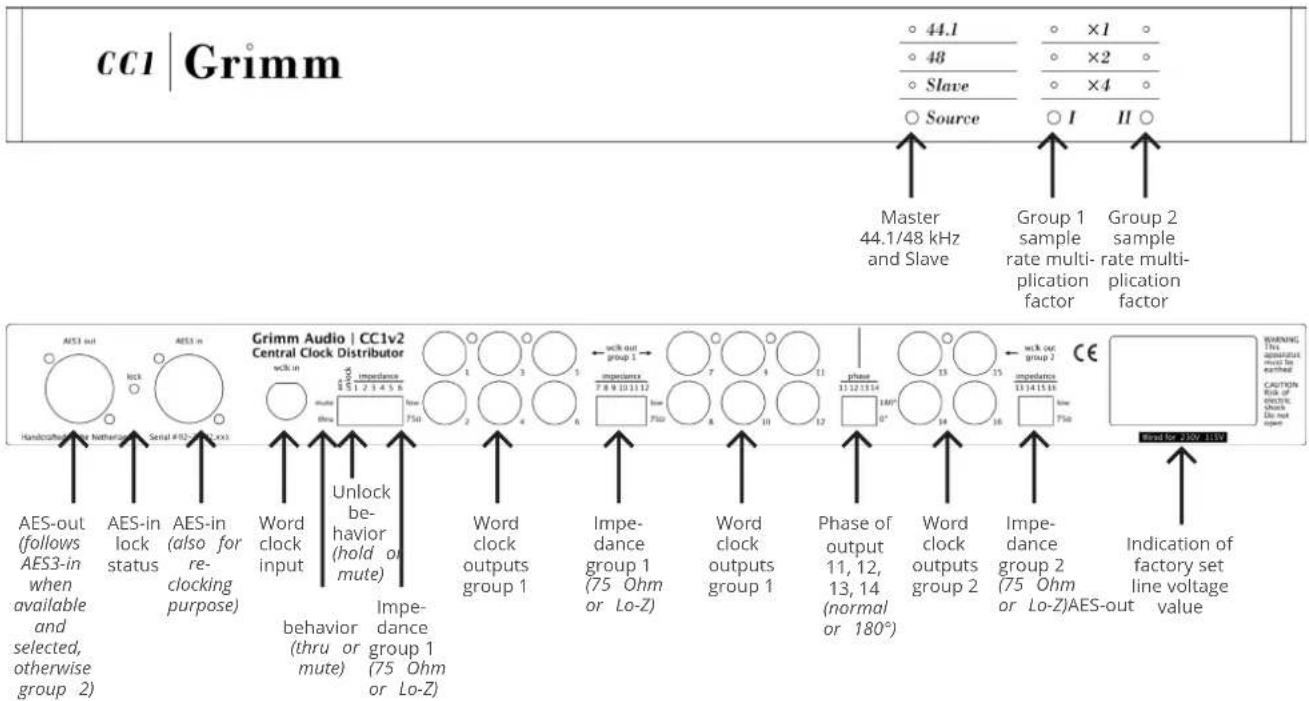
The leftmost front panel push-button selects between two base clock rates: 44.1kHz or 48kHz. The two other push-buttons determine the actual clock frequency transmitted across the 16 BNC outputs. They control in two groups. Group 1 are channels 1-12. The second push-button sets the multiplication factor for this group to 1x, 2x or 4x. Group 2 are channels 13-16, and their multiplication factor is set by the third push-button. Setting '48kHz' using the leftmost push-button, '1x' on the middle selector and '2x' on the rightmost selector will set the clock rate on group 1 BNC's to 48kHz and on group 2 BNC's to 96kHz.
The AES3 output has two functions, depending on the setting of the dip switch marked 'aes' on the rear. It determines whether the audio content found at the AES3 input is passed through to the output ('thru') or not ('mute'). In mute mode the AES3 data will be black and run at the rate selected for group 2. In thru mode, the AES3 output will obviously run at the same rate as the AES3 input. On loss of input signal, the output will remain at the same sampling rate.
The exact behaviour of the AES3 output in master mode depends on the use case:
- No signal connected to the AES3 input. The AES3 output is a black signal (no audio) with the same sampling rate as the Group 2 BNC outputs. The channel status bits indicate "Grade 1 reference" if the CC1 has gone through the optional frequency calibration, otherwise "Grade 2 reference". The AES lock indicator on the rear is off.
- A signal is applied to the AES3 input that is not synchronous to the CC1. The AES3 output is a black signal with the same sampling rate as the Group 2 BNC outputs. The AES lock indicator on the rear blinks.
- A signal is applied to the AES3 input that is synchronous to the CC1, but the 'aes' dip switch is set to 'mute'. The AES3 output will still be black and synchronous. The presence of the aes signal has no
effect. In master mode with the 'aes' dip switch set to 'mute', any signal at the AES3 input is basically ignored, except that the 'aes lock' light on the rear will be on to indicate the presence of a synchronous input.
- A signal is applied to the AES3 input that is synchronous to the CC1, and the 'aes' dip switch is set to 'thru'. The AES3 output fully copies audio and subcode data (but not the jitter!) from the AES3 input. In this mode the AES3 output will never indicate 'grade 1' as AES11 requires a black signal. The 'aes lock' light is on.
- If the input signal is lost from case 4, the sampling frequency setting is retained, as sudden loss of signal is most likely accidental. This is different from case 1 where an AES3 input signal was never present. If the removal of the AES3 input was on purpose, changing the group 2 multiple on the front will return to case 1, and the AES3 output will once again be synchronous to the selected multiple of group 2.
Slave mode
Slave mode is the third setting on the leftmost selector. In slave mode, the CC1 will look at the word sync input as well as the AES3 input for a valid signal. Slave mode permits the following use cases:
- Word sync only. Upon selection of slave mode, the CC1 selects the word sync input. The middle and right selector once again set groups 1 and 2 to a multiple of the base rate. The AES3 output will be black, synchronised to group 2 and the channel status is marked "no reference". Upon loss of lock, the output frequency will be held constant, see case 4.
- AES3 only. Upon selection of slave mode, the CC1 selects the AES3 input. The 'aes' dip switch at the rear selects whether the audio data is transmitted (thru) or not (mute). In thru mode, the AES3 output will obviously run at the same multiple as the AES3 input. In mute mode it will be synchronous to group 2, audio is black and marked "no reference". Upon loss of lock the output
rate will be held constant, see case 4. The 'AES lock' light on the rear will be on as long as the CC1 PLL is locked.
-
Both AES3 and word sync are present. Word sync will take precedence over the AES3 input. In thru mode the AES3 output will produce a jitter-free copy of the AES3 input, provided the input signal is synchronous. In mute mode the AES3 input will be ignored altogether. Upon loss of the AES3 input the AES3 output will revert to black. Upon loss of the word sync input the output frequency will be held constant (within 1 ppm of the last detected frequency) and the front slave light will blink to indicate an error. The fault condition is cleared either by reattaching the word sync or by cycling the source selector through the two master modes back to slave mode to force the CC1 to lock to the AES3 signal instead. The CC1 will never automatically switch from word sync to AES3 to prevent clock loops.
-
No valid signal on either word sync or AES3 input. The response is now determined by the dip switch named 'unlock'. When set to "thru", the clock frequency will be held constant within 1 ppm of the last valid measured
frequency. When set to "mute", the outputs will be muted. In both cases the slave light will blink to indicate an error. The mute mode is advantageous at for instance post production where the clock usually is out of sight in a machine room. Upon loss of lock, all clocks disappear and your software automatically provides a warning. The thru mode has an advantage in for instance live recording or Public Address. Here sound should never mute, whatever happens.
Lock indication
The CC1 detects whether the input signal is a multiple of 44.1kHz or 48kHz, and indicates this on the LEDs above the source push-button. The frequency multiple settings of groups 1 and 2 remain as set by the user. While the CC1 acquires lock, the slave light will blink. This can take up to 20s, on account of the CC1's extremely slow PLL design (see chapter 7, "Jitter and PLL's explained"). Once frequency lock is achieved, the slave LED will come on continuously. The PLL will then settle to 0° phase lock with the input in an even slower mode. The smallest achievable phase error depends mostly on the stability
Manual CC1 © Grimm Audio
of the incoming clock. The static (average) phase error is factory-aligned to be within 50ns.
The 'lock' LED on the rear indicates the AES3 receiver status:
- Off: No AES3 signal present.
- On: AES3 signal present and found to be synchronous with the CC1.
- Blinking: An AES3 signal is present but it is out of sync with the CC1.
Impedance
The ‘impedance’ DIP switches on the rear allow each individual output to be set to low-impedance (25 ohms typical) or characteristic (75 ohms) impedance. The switches are factory set to 75 ohms. Should the receiving device have problems recognising the word sync signal, you might try the low impedance setting.
Word sync connections are usually 5V square waves transmitted over 75 ohm (video) coax cables. Although the word clock frequency itself is relatively low, the transitions are steep. Taken as a whole, word sync is a wideband signal, necessitating characteristic termination at least at one end of the cable. Single-terminated lines are usually terminated on the source end. Better still is series termination on the transmit end and parallel termination on the receiving end. This minimises reflections even when the cable impedance is not exact. Double termination like this produces a 6dB loss, resulting in a 2.5V signal. All Grimm Audio products are designed to work in this manner.
There is no standard defining word sync connections. As a result, implementations vary across makes. Outputs may be series terminated or low impedance, DC or AC coupled. Inputs may be parallel terminated or high impedance. This yields 8 permutations, all of them encountered in the wild. The CC1 input will correctly interpret all variants without user manipulation, but the impedance of the CC1's outputs may need to be set low in some cases. A parallel-terminated input expecting a 4V input signal will only work with the CC1's output impedance set low. A fair number of products were found to have parallel terminated input but stop
working around 2.5V which is why the CC1 puts out a slightly higher-than-normal voltage in order to allow correct operation in the factory preset mode.
Nevertheless, some equipment will only respond correctly when the output impedance DIP switch is set to low.
Phase
Channels 11 to 14 can be polarity-reversed ( 180^ phase shift) to cater for equipment that uses the falling edge to synchronise on instead of the rising edge. Should you encounter operational problems with equipment, even though it is locked, check its manual for any mention of clock phase and try the 180^ switch setting.
AES and unlock switches
The 'aes' and 'unlock' switches can be set to "mute" or 'thru'. The behavior of the CC1 in these modes is described in the sub-chapters 'Master mode' and 'Slave mode' above.
Key Lock mode
If your CC1 is used in one setting most of the time you can use 'Key Lock' mode to prevent clocking errors by accidental pressing of control buttons on the CC1's front panel. In this mode the CC1 does not respond to the push of any button. 'Key Lock' mode is engaged by holding the '44.1/48/Slave' button during power up. It will then lock the mode that was set before the last power down. To leave 'Key Lock' mode, hold the '44.1/48/Slave' button during power up again.
5. Setting up the studio
In a digital studio all equipment will need to be synchronised. If all there is are two boxes, one sending and one transmitting, all that is needed is a digital signal and the recipient will lock to that. When multiple sources are feeding into one recipient (e.g. a digital desk connected to several digital recorders and converters), all sources will need to be synchronous. This is what a house sync (aka master clock) is for.
Several formats are in use. The AES promotes a standard called AES11 that uses an AES3 link, but most equipment tends to use a word sync signal on a BNC connector. The AES11 standard is to be amended to include this practice. We think this is a good move, since the purity of a clock recovered from an AES3 link is rather susceptible to issues like cable length and bandwidth limitations. The AES3 output on the CC1 is provided to cater for the few equipment that needs AES11 over AES3. When the output is not used for this purpose, it doubles as a jitter removal function for any AES3 signal (provided it is synchronous with the CC1).
Manual CC1 © Grimm Audio
Most studios that have introduced a house sync have noticed a change in the overall sound quality of their equipment. Usually for the better, sometimes for the worse. At issue is jitter (akin to wow and flutter, but then applied to the sampling clock). Chapter 7 "Jitter explained" will go into more details. The important point to remember is that jitter affects audio quality only at points in the chain where an actual time-based conversion is taking place, typically AD and DA converters but also in asynchronous sampling rate converters.
Connection
The CC1 will usually be located in the machine room. Each device connected to the CC1 is set to 'slave to word sync'. The best connection scheme is 'star distribution' with each output of the CC1 connected to one device. The sixteen outputs will normally suffice. Daisy chain connections are best avoided, as are T-junction connections. The latter will most likely fail anyway because of the lack of standardisation of termination impedance
and signal level, not to mention mechanical failure of T-junctions themselves.
Try to prevent circulating ground currents through the coax cables (ground loops). As coax cables go, they are unbalanced and currents flowing through the cable shields will impose an error voltage on the signal, causing jitter at the receiving end that wasn't there at the transmitting end. One common cause of circulating currents is leakage current through the power supply of an ungrounded product. Another is voltage drop between the earth ground connection between devices that are located far apart. Minimizing the loop area encircled by the entire loop, comprising the word sync cable and the mains cords is usually a good idea. By all means, never defeat the safety earth connection of any device that is designed to have an earth connection. Lifting grounds may produce a lethal shock hazard.
The CC1 itself has a low-impedance reference plane at the rear, insuring that it will never be affected by circulating currents. Not all equipment is designed in this manner unfortunately.
AES3 reclocking
Apart from the word sync input and sixteen outputs, the CC1 also sports an AES3 input and output. The output can carry an AES11 DARS signal but it may also be used to transmit a re-clocked (de-jittered) copy of the signal at the AES3 input. This may be useful when driving a jitter sensitive device lacking a word sync input, most typically an outboard DAC in the monitoring system or a digital input loudspeaker.
The reclocking function is available in all configurations, that is, master, slaved to word sync or slaved to the AES3 input itself. Apart from the latter trivial case this implies that the source of the AES3 signal should itself be somehow synchronised to the CC1. Setting the 'aes' switch to 'thru' activates the reclocking mode, passing maximally jitter-free signal to e.g. a DAC. In most cases this will improve replay quality significantly.
In consumer use, most equipment features RCA S/PDIF connectors in stead of XLR AES3 connectors. To use the CC1 in such a hifi setup, special S/PDIF to AES3 and AES3
to S/PDIF conversion cables are needed with build-in impedance and signal level adaptation circuitry. Grimm Audio has these cables available in its web shop.
Clock Loop
A clock loop is a runaway situation where two devices are slaved to each other, for instance the CC1 slaved to a recorder which in turn is slaved to the CC1. Neither device is the clock master and the result will usually be that the clock frequency ends up at an extreme of the tuning range of one of the devices. Before setting the CC1 to slave, insure that the clock input originates from a master.
PLL setting in attached devices.
Audio devices capable of locking to an external clock use a phase-locked loop to do so. Details of this are covered in our white paper "PLL and clock basics" that can be found in the downloads section of the CC1 page on our website. An important thing to know for a CC1 user is that some products have two modes, usually called
Manual CC1 © Grimm Audio
'fast/wide' or 'slow'. The slow setting has the best suppression of incoming jitter, and is the optimum choice when the incoming clock is polluted. The downside of the slow setting is that the jitter in the recovered clock is fully dominated by the clock oscillator that forms part of its PLL. If the incoming clock happens to be much stabler than that, the slow mode will actually end up adding jitter. The latter scenario is almost guaranteed to be the case with the CC1, which is significantly cleaner than any clock oscillator we've found in commercially available audio products so far. As a rule, in this case it is usually better to select the 'fast' mode. In fast mode, the PLL will track the incoming clock more closely and if the incoming clock is extremely clean, the same will go for the regenerated clock.
Products that have a fixed slow PLL, such as those from Apogee, dCS, Lynx or Prism Sound, will improve comparably little compared to products with a switchable or relatively fast PLL like those from Avid, Lavry Engineering, MOTU, Mytec, SSL or RME.
Syncing to Video
Before complicated digital studios became practical, video studios have been using house syncs for decades. As soon as more than one camera is used, all sources need to be synchronised. Apart from a time base reference there is also a need to know the actual timing of a frame. This information is provided by time codes. Although the time code signal is of course synchronous with the video sync, it is usually transmitted separately. In some cases the 'LTC' code is used as main video sync, but fortunately it is going out of fashion. LTC is probably the least stable time reference around.
Enter digital audio. The audio track now needs to be synchronised to the picture. Word sync has a better time resolution than video sync, but still the most common practice is locking the audio clock to the video clock. Even modern digital video production practice tends to lock audio to an analogue video signal. This is unfortunate because low jitter is not exactly a design spec for a video sync generator.
The CC1 cannot slave to video sync directly. In order to avoid direct crosstalk between the black-burst generator or receiver and the audio clock, we have omitted video sync functionality. Our best advise is to use the CC1 as the audio master and slave all video to the audio word sync. If you nevertheless do need to slave the audio system to video sync you can either buy our VCC 'Video to Word Clock' converter or use any other generic video to word clock converter. Connect the retrieved word clock to the CC1's word clock input and have the CC1 clean up the sync and distribute clock to the audio devices as usual. The extraordinary stability of the CC1's PLL will make sure the result comes as close as possible to making the audio chain master.
Hints
- Select decent quality 75 Ohm coax cables and certainly do not skimp on the quality of the connectors.
-
Make cables no longer than necessary.
-
Cables add propagation delay. It is exceedingly rare for differences in clock phase to affect the interoperability of connected audio equipment, but if it happens, using equal length cables throughout helps.
- Disconnect unused gear.
- Ideally do not leave the word clock input connected when the CC1 is master. Although unlikely (the CC1 has a relay to actively disconnect the input when not in use), there is a possibility of cross-talk from the input clock to the outputs. Likewise, do not leave an AES3 cable attached if not needed.
6. Jitter and PLL's explained
Jitter is an instability in the timing of a clock signal. Ideally the rising or falling edges of a clock signal are all separated by exactly the same amount of time. In reality, the timing is more uncertain. Figure 1 below shows the time-domain view of the problem.
We can also look at the problem spectrally. An ideal clock has only a single frequency components (and harmonics). All energy is concentrated on an infinitely narrow frequency band, see the top graph in figure 2. When jitter is present, side bands occur. Some spectral energy is located away from the clock. The faster the timing chatters, the further away from the main frequency you'll find energy.

natural_image
Pure electrical circuit lines without any symbolsFigure 1. A stable and a jittery clock signal
The red curve in the bottom graph shows only random jitter. Sometimes jitter is periodical and then you wouldn't see a smooth slope but sharp peaks. An important note is that frequency accuracy has absolutely nothing to do with jitter at all. The red graph shows a jittery clock with an exactly correct frequency, say 44100.0000000Hz, the blue one shows a clock that's

line
| Frequency | Amplitude | | --------- | --------- | | Low | Peak | | High | Peak |Figure 2. Spectra of clock signals
somewhat off but otherwise brilliantly stable. A frequency error can be annoying from a practical perspective, but as far as signal quality is concerned you're better off with a stable clock at an inexact frequency.
Jitter is not a problem in fully digital processes. As long as it isn't so large that a processor can't distinguish the previous bit from the next, all-digital processes are completely indifferent about jitter. The problem occurs when you go from the analogue domain into the digital domain or back. Digital audio presumes uniform sampling. That way, given a string of numbers and knowledge of the sampling interval, you can perfectly reconstruct a sampled signal. With jitter that theory falls apart.
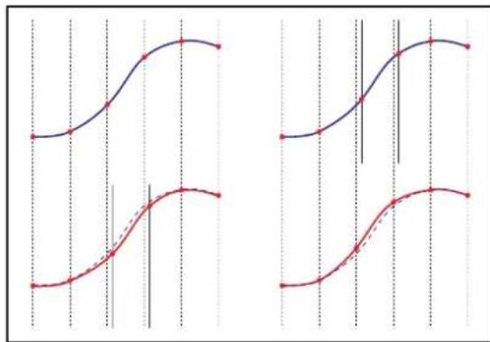
Imagine the blue analog signal top left in figure 3. The AD converter samples it at neatly uniform intervals. Bottom left, the DA converter reconstructs the correct values but it gets the timing wrong. The difference between the red and blue curve shows the error. Or take the converse in the right column: the DAC is fine
line
| X | Blue Line | Red Dashed Line | |----|-----------|-----------------| | 0 | 0.5 | -0.5 | | 1 | 0.6 | -0.4 | | 2 | 0.7 | -0.3 | | 3 | 0.8 | -0.2 | | 4 | 0.9 | -0.1 | | 5 | 1.0 | 0.0 | | 6 | 1.1 | 0.1 | | 7 | 1.2 | 0.2 | | 8 | 1.3 | 0.3 | | 9 | 1.4 | 0.4 | | 10 | 1.5 | 0.5 | | 11 | 1.6 | 0.6 | | 12 | 1.7 | 0.7 | | 13 | 1.8 | 0.8 | | 14 | 1.9 | 0.9 | | 15 | 2.0 | 1.0 | | 16 | 2.1 | 1.1 | | 17 | 2.2 | 1.2 | | 18 | 2.3 | 1.3 | | 19 | 2.4 | 1.4 | | 20 | 2.5 | 1.5 | | 21 | 2.6 | 1.6 | | 22 | 2.7 | 1.7 | | 23 | 2.8 | 1.8 | | 24 | 2.9 | 1.9 | | 25 | 3.0 | 2.0 | | 26 | 3.1 | 2.1 | | 27 | 3.2 | 2.2 | | 28 | 3.3 | 2.3 | | 29 | 3.4 | 2.4 | | 30 | 3.5 | 2.5 | | 31 | 3.6 | 2.6 | | 32 | 3.7 | 2.7 | | 33 | 3.8 | 2.8 | | 34 | 3.9 | 2.9 | | 35 | 4.0 | 3.0 | | 36 | 4.1 | 3.1 | | 37 | 4.2 | 3.2 | | 38 | 4.3 | 3.3 | | 39 | 4.4 | 3.4 | | 40 | 4.5 | 3.5 | | 41 | 4.6 | 3.6 | | 42 | 4.7 | 3.7 | | 43 | 4.8 | 3.8 | | 44 | 4.9 | 3.9 | | 45 | 5.0 | 4.0 | | 46 | 5.1 | 4.1 | | 47 | 5.2 | 4.2 | | 48 | 5.3 | 4.3 | | 49 | 5.4 | 4.4 | | 50 | 5.5 | 4.5 | | 51 | 5.6 | 4.6 | | 52 | 5.7 | 4.7 | | 53 | 5.8 | 4.8 | | 54 | 5.9 | 4.9 | | 55 | 6.0 | 5.0 | | 56 | 6.1 | 5.1 | | 57 | 6.2 | 5.2 | | 58 | 6.3 | 5.3 | | 59 | 6.4 | 5.4 | | 60 | 6.5 | 5.5 | | 61 | 6.6 | 5.6 | | 62 | 6.7 | 5.7 | | 63 | 6.8 | 5.8 | | 64 | 6.9 | 5.9 | | 65 | 7.0 | 6.0 | | 66 | 7.1 | 6.1 | | 67 | 7.2 | 6.2 | | 68 | 7.3 | 6.3 | | 69 | 7.4 | 6.4 | | 70 | 7.5 | 6.5 | | 71 | 7.6 | 6.6 | | 72 | 7.7 | 6.7 | | 73 | 7.8 | 6.8 | | 74 | 7.9 | 6.9 | | 75 | 8.0 | 7.0 | | 76 | - | - | | (Note: The red dashed line is not explicitly labeled in the image) but corresponds to the y-axis label 'Value' in the chart.Figure 3. Jitter in AD (top) and DA (bottom) converters
but the ADC took samples at the wrong time. The effect is much the same. What's worse in this case is that the recorded numbers are now wrong. In the previous case we could use a better DAC, with a jittery ADC the damage is unrecoverable.
PLL's
Converter chips need a high frequency clock signal, usually something around 22MHz. It is always made by a local oscillator (anything from a simple RC oscillator in a receiver chip to a crystal oscillator) regardless of whether the unit is operating in master or slave mode. This local oscillator is indispensable: external sync signals may be AES/EBU, a sample rate frequency word clock or even a video signal, neither of which are of any direct use to the AD/DA. Instead, the local oscillator is sped up or slowed down to make it run in step with ("locked to") the sync signal. A system that uses a local oscillator and pulls it in sync with an external signal is called a Phase Locked Loop (PLL). A 'phase detector' compares the local clock with the external sync signal and puts out a signal when the local oscillator runs too fast or too slow.
Now, the PLL will track the external sync closely, but not too closely. Unwanted fluctuations (jitter) of the external sync signal are to be ignored but if the local oscillator drifts off it should be slowly pulled back into step. So
how does the PLL tell the difference? It can't. It sees only the difference between the two clocks. All it can do is ignore short term differences (high-frequency jitter), whilst tracking slower fluctuations (low-frequency jitter). After all, a slow change could be due to drifting of either the external sync signal or the local oscillator. Either way, the PLL must get the local oscillator to follow the sync at long last, otherwise lock is lost.
The cut-off point between "slow" errors and "fast" errors (known as the 'PLL bandwidth') is chosen by the designer, based on an assumption of how stable the local oscillator is compared to the external sync signal. Above the cut-off point, the PLL will not reproduce any errors present in the input, but neither will it be able to correct errors committed by its own local oscillator.
Figure 4 gives the transfer of a basic PLL, designed to have a cut-off frequency of 4kHz. Mark that in this graph we are not looking at audio frequencies, but at jitter (or 'fluctuation') frequencies. The blue curve shows the attenuation of input jitter. The red curve shows the attenuation of the local oscillator's jitter. Below the cut-

line
| x | Red Line | Blue Line | | -------- | -------- | --------- | | 100 | -40 | 0 | | 1000 | -10 | 0 | | 1e4 | 0 | 0 | | 1e5 | 0 | -30 |Figure 4. Attenuation of input (blue) and local (red) jitter by a PLL
off frequency the external oscillators' jitter dominates, above cut-off the local oscillators'. A cut-off frequency at 4 kHz or higher can be found in AES/EBU receivers and general word clock inputs. If he regards the quality of his local clock highly, the designer of a PLL can decide to put the cut-off point much lower, for instance at 10 Hz or even further down. This makes for a 'slow' PLL with a very narrow bandwidth.
A quick way of seeing if a PLL is slow or fast is to see how long it takes to achieve lock. Usually, slow PLL's also
take a while to lock. The CC1 takes about 40 seconds to lock and has a 0.1Hz bandwidth. Typical AES/EBU receiver chips lock within a few samples and have a bandwidth of around 10kHz.
If the local clock is very clean, a narrowband PLL is the best choice because all but the lowest-frequency jitter in the external sync is rejected. A converter designed along those lines will sound stellar under all conditions. If the external sync is very clean, a wideband PLL is the best choice because the local oscillator's own errors will be corrected. This is the case where a good external sync like the CC1 improves a budget converter, or even a pricey one, beyond expectations.
If the designer guesses wrong however, a too-fast PLL might end up forcing an otherwise fine local oscillator to reproduce faithfully every bump and hiccup in the external sync signal. Equipment constructed along these lines sounds good in master mode but will only improve in slave mode if the external sync is stabler than the internal oscillator. An unstable external sync actually makes it sound worse.
Manual CC1 © Grimm Audio
Alternatively a too-slow PLL might not correct a local oscillator of suboptimal quality. In that case, jitter performance is bad regardless of the quality of the external clock. And here lies the rub: a slow PLL will always make a converter sound the same, but not necessarily good. If a converter is insensitive to external jitter, that alone is no indication that its internal jitter is low. A slow PLL shuts the door to external jitter, but also to any improvement to be had from external clocking with a very stable source.
In short, one cannot expect an external clock to work miracles every time. If the PLL of the receiving device is slow, the sound quality will be independent of the quality of the external clock, for better or for worse. If the PLL is fast, real improvements can be had.
By example, figure 5 shows the result of measurements on a well known DAW converter. The jitter performance, measured at the converter chips' clock pin, improves substantially at jitter frequencies below 200 Hz when slaved to a CC1.

line
| Hz | DAW (master) | DAW slaved to CC1 | CC1 | |------|--------------|-------------------|---------| | 20 | ~10^5 | ~10^4 | ~10^3 | | 50 | ~10^5 | ~10^4 | ~10^3 | | 100 | ~10^5 | ~10^4 | ~10^3 | | 200 | ~10^5 | ~10^4 | ~10^3 | | 500 | ~10^5 | ~10^4 | ~10^3 | | 1k | ~10^5 | ~10^4 | ~10^3 | | 2k | ~10^5 | ~10^4 | ~10^3 | | 5k | ~10^5 | ~10^4 | ~10^3 | | 10k | ~10^5 | ~10^4 | ~10^3 | | 20k | ~10^5 | ~10^4 | ~10^3 |Figure 5. Jitter performance of a well known DAW converter
7. Specifications
The CC1 clock PLL is a hybrid analog / digital design, based on a discrete ultra-low jitter crystal oscillator. In master mode the oscillator is temperature compensated. Local shunt regulators featuring 120 dB power supply rejection and a high impedance supply path, make sure that all variations in load current are kept local to the circuit: the power buss and ground carry only DC current.
• Word clock input impedance 75 Ohm.
• Word clock input sensitivity better than 1 Vpp.
• Word clock output impedance 75 Ohm or 25 Ohm ('low') on selected channels.
• Word clock output voltage, terminated 2.7 Vpp, unterminated 5.5 Vpp. DC coupled.
• Latency word clock in - word clock out: adjusted to less than 50 ns (but depends on input clock jitter).
• Internal intrinsic clock jitter 2,1 ps RMS (> 10 Hz).
- Clock frequency master mode: 1, 2 or 4 times 44.1 or 48 kHz ± 10 PPM, 5 - 50 °C.
- PLL performance (slave mode):
■ 90 dB attenuation @ 10 Hz, improving at 60 dB/dec above that.
■ Pullability of clock frequency: ± 50 PPM (conform AES11 Grade 2).
• Maximum ambient temperature: 50 °C.
• Life expectancy power supply electrolytics > 45.000 hours. Power supply voltage range +/- 20%
- Fuses:
■ 120V (USA): fuse 500 mA
■ 100V (Japan): fuse 500 mA
■ 230V (EU): fuse 250 mA
- Weight: 4 kg
• Dimensions: 430 x 200 x 44 mm. Power consumption: 15 W.
- Wood type of front: Abachi.
8. Grimm Audio Limited Warranty
Grimm Audio BV ("Grimm Audio") warrants this product to be free of defects in material and workmanship for a period of two (2) years for parts and for a period of two (2) years for labor from the date of original purchase. This warranty is linked to the serial number of the device and can be transferred to second hand owners if they can show their purchase bill.
The original owner can extend his limited warranty to a period of five (5) years for labor and parts if he becomes member of the Grimm Audio Community and sends his purchase details to the Grimm Audio factory via the webform at grimmaudio.com/warranty. The extended warranty is enforceable only by the original retail purchaser and cannot be transferred or assigned.
During the warranty period Grimm Audio shall, at its sole and absolute option, either repair or replace free of charge any product that proves to be defective on inspection by Grimm Audio or its authorized service representative. In all cases disputes concerning this warranty shall be resolved as prescribed by law. To obtain warranty service, the purchaser must first call or write Grimm Audio at the address and telephone number printed below to obtain instructions where to send the unit for service. All enquiries must be accompanied by a description of the problem. All authorized returns must be sent to Grimm Audio or an authorized Grimm Audio repair facility postage prepaid, insured and properly packaged. Proof of purchase must be presented in the form of a bill of sale or some other positive proof that the product is within the warranty period. Grimm Audio reserves the right to update any unit returned for repair. Grimm Audio reserves the right to change or improve design of the product at any time without prior notice.
This warranty does not cover claims for damage due to abuse, neglect, alteration or attempted repair by unauthorized personnel, and is limited to failures arising during normal use that are due to defects in material or workmanship in the product.
In no event will Grimm Audio be liable for incidental, consequential, indirect or other damages resulting from the breach of any express or implied warranty, including, among other things, damage to property, damage based on inconvenience or on loss of use of the product, and, to the extent permitted by law, damages for personal injury.
© 2021, Grimm Audio BV. All rights reserved
Grimm Audio CC1 manual v2.2, 15/06/2021
Reproduction in whole or in part is prohibited. Specifications subject to change without notice.
Grimm Audio, The Netherlands General questions: info@grimmaudio.com Support questions: support@grimmaudio.com Tel. +31 40 213 1562
Manual CC1 © Grimm Audio
cc1 Grimm

Grimm Audio BV
The Netherlands
+31 40 213 1562
info@grimmaudio.com
www.grimmaudio.com


- Table of Contents
- Introduction
- Important Safety Instructions
- Please follow these precautions when using this product:
- Installing
- Unpacking and Inspection
- Mounting the CC1
- AC Power hookup
- Operation
- Master mode
- Slave mode
- Lock indication
- Impedance
- Phase
- AES and unlock switches
- Key Lock mode
- Setting up the studio
- Connection
- AES3 reclocking
- Clock Loop
- PLL setting in attached devices.
- Syncing to Video
- Hints
- Jitter and PLL's explained
- PLL's
- Specifications
- Grimm Audio Limited Warranty
- cc1 Grimm
Brand : Grimm Audio
Model : CC1
Category : Audio/video converter