
ZP5 - Binoculars MINOX - Free user manual and instructions
Find the device manual for free ZP5 MINOX in PDF.


| Product Type | Binoculars |
| Brand | Minox |
| Model | ZP5 |
| Magnification | 8x |
| Objective Lens Diameter | 25 mm |
| Field of View | 130 m at 1000 m |
| Exit Pupil | 3.1 mm |
| Eye Relief | 15 mm |
| Close Focus | 2 m |
| Prism Type | Porro |
| Lens Coating | Fully multicoated |
| Dimensions (H x W x D) | 120 x 100 x 50 mm |
| Weight | 300 g |
| Waterproof | Yes, nitrogen filled |
| Focus System | Center focus wheel |
| Diopter Adjustment | Yes, right eyepiece |
| Interpupillary Distance | 56-74 mm |
| Power Source | None (manual operation) |
| Cleaning | Use lens cloth and blower |
| Safety Warning | Never look directly at the sun |
| Warranty | 2 years |
Frequently Asked Questions - ZP5 MINOX
User questions about ZP5 MINOX
0 question about this device. Answer the ones you know or ask your own.
Ask a new question about this device
Download the instructions for your Binoculars in PDF format for free! Find your manual ZP5 - MINOX and take your electronic device back in hand. On this page are published all the documents necessary for the use of your device. ZP5 by MINOX.
USER MANUAL ZP5 MINOX
natural_image
Technical line drawing of a mechanical component with multiple cylindrical parts and a tape measure (no text or symbols)natural_image
Technical line drawings of mechanical components with no visible text or symbolsnatural_image
Technical diagram of a mechanical component with labeled parts (R1–R6), no readable text or symbols beyond labelsAbb. 1

Welcome to MINOX! 23
Overview 25
Scope of delivery 25
Magnification setting 25
Diopter adjustment 26
Parallax adjustment 27
Reticle illumination and battery change 28
Reticle adjustment 30
Reticle features 33
- Mrad Scale 33
- AQRAS Scale 34
Lens cap 35
Care and maintenance 35
Mounting 36
Troubleshooting 37
Fogging 37
Serial number 37
Service 38
Conditions of Warranty 39
Extended MINOX Warranty Service 39
- MINOX Comfort Service 39
Technical data 40
Reticle subtensions 41
Dimensions 46
Welcome to MINOX!
You're about to join those who have long revered MINOX as an exceptional value in performance sport optics – that rare, understated blend of extraordinary features, quality, and durability for many years of reliable use.
These instructions are intended to provide you with the information you need to take full advantage of the many features we've built into your MINOX ZP5 riflescope. Information on proper adjustment and care is included.
Before using your MINOX ZPS riflescope, please read the instructions carefully.
Thorsten Kortemeier
Managing Director
If you have additional questions or comments, please contact your authorized MINOX dealer or local MINOX distributor.
MINOX GmbH
Walter-Zapp-Str. 4
35578 Wetzlar
Germany
Phone: +49(0)6441 / 917-0
E-Mail: info@minox.com
www.minox.com
MINOX ZP5
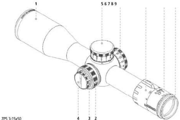
Overview
- Objective
- Parallax adjustment
- Illumination adjustment ring
- Battery compartment with screw cap
- Reticle adjustment (elevation)
- Reticle adjustment (Windage)
- Magnification ring
- Lock ring for diopter adjustment
- Diopter adjustment
Scope of delivery
- MINOX ZP5 riflescope
- Battery, type CR 2032, 3 Volt
- Eyepiece lens cap
- Lens cleaning cloth
- Instructions
Magnification setting
To set the desired magnification, turn the power ring at the front of the eyepiece. Turning clockwise decreases the magnification and turning counterclockwise increases the magnification.

The MINOX ZP5 has a wide power ring with a fin in the center of the adjustment range to ensure easy and secure operation even when wearing gloves.
The important magnification values on the power ring are black on white in order to simplify reading and adjusting the power ring under difficult lighting conditions.
Diopter adjustment
The purpose of the diopter adjustment is to adapt the scope to the user's eye and to compensate for individual visual acuity. If corrective glasses are worn while shooting, the glasses must also be worn when adjusting the diopter.
The MINOX ZPS has a lock ring to prevent inadvertent turning of the diopter adjustment ring, e.g. when twisting the eyepiece protection cap into position. Turn the ring counter-clockwise to release the locking mechanism and clockwise to lock the diopter adjustment ring into place. This lock is designed to prevent accidental adjustment of the diopter. However, under use of great force, the diopter adjustment can still be turned.
Note: When making adjustments to your riflescope, be sure to follow the safety precautions of the rifle manufacturer.

To adjust the diopter, turn the magnification to the highest power and loosen the lock ring. Aim the riflescope at a uniformly bright object in the distance like the overcast sky. Turn the diopter adjustment ring until the reticle is sharply focused. Look past the riflescope at the distant object and then through the riflescope – the reticle should be perfectly sharp. If the reticle appears sharply only after a moment of looking through the riflescope, the diopter is not correctly adjusted. Although the eye can compensate somewhat for a sub-optimal setting, this can nevertheless result in eye fatigue under prolonged use.
This diopter setting can now be locked into place with the lock ring and will have to be adjusted again only with changing eyesight.
Parallax adjustment
Parallax is the visible movement of the reticle over the target image. This occurs when the observing eye moves vertically or horizontally behind the riflescope and the scope has not yet been adjusted parallax-free to the target distance. This movement is also called parallax error and is a displacement of the apparent position of an object viewed along two different lines of sight. Parallax occurs when the plane of the target image in the scope is not at the same distance as the plane at which the reticle is visible. This difference causes the reticle in relation to the target image to appear out of focus.
The MINOX ZP5 riflescopes are equipped with a parallax adjustment knob to compensate for parallax errors from 50 m to infinity. The focus of the target image is adjusted to match the focus of the reticle. Parallax error is eliminated by bringing the focused target image into the same image plane as the reticle.

natural_image
Technical line drawing of a mechanical component with multiple circular parts and a cylindrical top (no text or symbols)To determine if the target image is parallax-free at the desired distance, move your head up and down, and from side to side while looking through the rifle-scope. This will cause the eye pupil to move within the exit pupil of the riflescope. If the reticle moves but the target image does not (the rifle must be kept absolutely steady), then the parallax error has not been sufficiently corrected.
If the reticle moves in the opposite direction than the movement of the head (e.g. the head moves to the left, the reticle moves to the right), then the target is farther away than the parallax-free distance. In this
case, turn the parallax adjustment knob counterclockwise to increase the parallax-free distance and adjust it to the target distance.
If the reticle moves in the same direction as the movement of the head (e.g. the head moves to the left, the reticle moves to the left), then the target is closer than the parallax-free distance. In this case, turn the parallax adjustment knob clockwise to lower the parallax-free distance and adjust it to the target distance.
If the reticle no longer moves over the target image when moving the head, then the parallax error has been completely corrected. If the target image remains somewhat out of focus even after the parallax error has been corrected, please check the diopter adjustment setting.
The parallax adjustment ring does not have a distance scale. The engraved scale merely indicates the direction in which to turn the knob for close and far distances. Due to thermal expansion of the riflescope and varying atmospheric conditions, a distance scale cannot be accurate under all circumstances and could lead to a false sense of precision. If high precision is required, the parallax should always be adjusted
under the current conditions using the procedure described above.
In some cases it may be desirable to do a rough pre-adjustment to get an approximate parallax setting before a target is acquired, or the user may want to use a standard setting from which to start when the exact location of the target is still unknown. In order to facilitate this, the markings on the parallax knob are designed in a way that allows good orientation within the 180° adjustment range. Approximate parallax settings that are significant to the individual user can be memorized and preset without having to acquire an actual target.
Reticle illumination and battery change
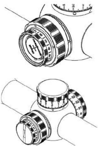
The illumination adjustment ring and battery compartment are integrated within the parallax adjustment knob on the left side of the main tube.
The battery compartment is covered by a screw cap. To insert or replace the battery, turn the screw cap counterclockwise using a coin or suitable tool. Push
on the edge of the battery with your fingernail to release it from the battery holder. Insert the battery with the minus pole towards the riflescope and screw the cap tightly into place.
Use only new and undamaged CR 2032 batteries from a high-quality manufacturer.
The desired illumination intensity can be adjusted in 11 levels. There are tactile clicks for every setting. Between the brightness settings, there are "off"-settings so that a pre-selected brightness level can be activated with a single click.
The reticle illumination is automatically switched off when the brightness setting has not been changed for 3 hours. This prevents the battery from draining if the illumination has been inadvertently left on. The illumination reactivates after a change in brightness settings.
Note: The reticle illumination in the ZP5 riflescopes has been designed specifically for use in twilight or darkness. It can be finely dimmed such as not to overpower the target image even in almost complete darkness. The reticle illumination is not
natural_image
Technical line drawings of mechanical components with no visible text or symbolsintended for use in daylight. Even the brightest settings are barely visible in daytime. This is not due to dead batteries or a defect but corresponds to the intended use of the scope.
Reticle adjustment
The windage and elevation turrets have tactile and audible clicks and engraved markings in 0.1 mrad increments. One 0.1 mrad click (milliradian, also known as "mil") is equivalent to 1 cm / 100 m.
The elevation turret is equipped with a so-called Double-Turn (DT) feature. This means that two complete revolutions of the adjustment cap are available to make full use of the 28 mrad adjustment range without the clicks and scale markings being too close to each other. The scale markings on the elevation knob indicate the point of impact above the zero position. The elevation knob has two rows of numbers, the upper row of which indicates the second turn. At the beginning of the second revolution, white markings will appear in both windows at the base of the turret. These markings indicate that the upper secondary scale is in effect.
An "R" or "L" in front of the numbers on the windage tower indicates the direction in which the point of impact will be shifted when making windage adjustments. For example, to compensate for a crosswind from the right, which would cause the point of impact to shift to the left, turn the windage adjustment in the "R" direction until the desired point of impact has been reached. These markings correspond with the output of most ballistic programs in which the output of values for windage adjustments are preceded with an "R" or "L" as a prefix for the direction of compensation.
The riflescopes are available with "CW" (clockwise) or "CCW" (counterclockwise) turrets. The direction of rotation indicates the direction in which the caps must be turned to change the point of impact "up" or "right".
The elevation turret is equipped with a Zero Stop, limiting the rotation of the adjustment cap. The zero stop is permanent and does not need to be adjusted. It is designed to stop the rotation of the elevation cap a few clicks below the zero position. The windage turret is equipped with a stop to limit the windage adjustment range so that it cannot be turned more than half of a revolution.
While zeroing your rifle, adjust the elevation and windage knobs until the point of impact matches the point of aim. For example, if the impacts are too low, adjust the elevation upwards and if the impacts are too far right, adjust the windage towards "left".
The caps can be loosened using a 2 mm allen key and tightened again after turning the caps to the zero position. When the caps have been loosened, no clicks can be heard or felt, indicating that the caps have been successfully disengaged from the adjustment mechanism.
To set the knobs to zero after zeroing your rifle, slightly loosen the screws with a 2 mm allen key. About half a turn should be enough. Turn the knobs to the zero position (the indicator windows must be black). Tighten the screws only hand-tight. It is advisable to hold the shorter end of the key to avoid too much torque when tightening the screws.
Note: If while zeroing your scope you have reached the Zero Stop (for example if the shots are repeatedly too high and the elevation knob cannot be turned "down" any further), loosen the allen screws on the knob and turn it several mrads upwards. Push the

knob down and tighten the screws again. You will now have more adjustment range to achieve the desired point of impact. The same procedure can be carried out with the windage turret.
If the screws have been inadvertently loosened too much, the knob can be removed from the scope. To reinstall the knob, place it onto the turret, push it down and tighten the screws.
Note: If the elevation knob has been completely removed, the mechanism to indicate the second revo-
lution may be brought into a position that prevents the elevation knob from being turned more than one revolution (see fig. 1). Before the cap is reattached, make sure that the cylinder is in the right position, as seen in fig. 2 (this applies to CCW turrets – the groove in a CW turret would be pointed in the opposite direction). The cylinder can be properly aligned using a small screwdriver.
The adjustment mechanism is designed in such a way that the adjustment range of the reticle is rectangular. At the limits of the adjustment range there are internal stops and the adjustment knob cannot be turned any further in that direction. This means that when for example the elevation adjustment is at the limit of its range, the full windage adjustment range is still available (and vice versa). This design also prevents erratic behavior of the adjustment at the limit of the adjustment range (like a "jumping" point of impact) or damage to the internal adjustment mechanism. The whole specified adjustment range can be utilized without limitations.

natural_image
Technical diagram of a mechanical component with concentric circles and radial slots (no text or labels)Fig. 1

Fig. 2 Please note: correct position of the cylinder
Reticle features
The reticle in the MINOX ZPS is located in the 1st focal plane. This means that the reticle is magnified at the same ratio as the target image and that the reticle subtensions remain unchanged in relation to the image. Independent of the magnification, the reticle can be used to accurately determine range and trajectory compensation. All available reticles are equipped with illumination intended for use in twilight or darkness only. The illumination can be finely dimmed to avoid glaring or distraction from the target. The illumination is not intended for use in daylight.
Illustrations of the ZPS reticles can be seen from page 41.
Mrad Scale
The horizontal and vertical Mrad Scale is arranged symmetrically to the AQRAS Scale and is divided into 0.1 mrad increments, enabling measurements with an accuracy of down to 0.05 mrad, depending on the magnification. This is particularly useful for precise measurements when determining the distance to targets of known size by using the following formula:
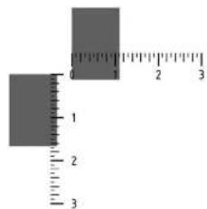
Target size [mm] ÷ scale value [mrad] = distance [m]
The horizontal measurement range is up to 6 mrad and the vertical measurement range is up to 5 mrad, if the crosshair lines are used as baselines.
The size of targets at known distances can also be determined. This can be useful if for example, a target is viewed at a known distance and the range to a similar-sized target at an unknown distance needs to be determined. This is the formula to determine the target size:
Scale value [mrad] · distance [m] = target size [mm]
While readings between the AQRAS Scale marks must be estimated, the Mrad Scale enables highly accurate readings of intermediate vaules or or very small targets. The Mrad Scale is the ideal complement for situations where enough time is available for particularly accuracy ranging.
When using the reticle to calculate the range to a target, the accuracy of the result is highly dependent on how exactly the size of the target is known. If a laser rangefinder is not available, or cannot be used due to weather conditions (fog, rain, snow), a suitable reticle can be an invaluable aid for range determination.
AQRAS Scale (Advanced Quick Ranging Scale) The AQRAS Scale is a universal stadiametric scale used to quickly determine the range to a target. Conventional scales limited to specific target sizes become useless if the target does not have the right size or if for example, the corresponding part of the target is obscured. By contrast, the AQRAS Scale works with any target of known size as well as for vertical or horizontal targets.
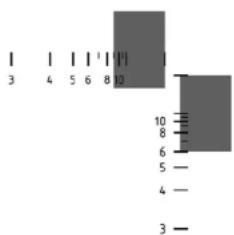
Using the AQRAS Scale is fast and easy: Align the baseline with the known measurement of the target, read the value and then multiply by the target size:
Target size [cm] · scale value = distance [m]
This can easily be done by mental calculation. The divisions required in the conventional mil formulas have been "integrated" into the AQRAS Scale. In this way, calculating the distance to a target can be determined without having to take your eye off of the target.
The scale always uses the same baseline to align onto the target. There is no need to switch between several scale marks – intermediate values can be determined easier and faster. The distance to a target that is 1 m high or wide can be read directly (scale value x 100 m). The AQRAS Scale uniquely combines the speed of conventional scales adapted to targets of 1 m height with the flexibility of use on targets of varying sizes.
To calculate the distance to a target, the baseline is aligned either to the right or on top of known dimension of the target. Intermediate values can be estimated. The attained accuracy for intermediate values is lower than when using the Mrad Scale, but on the other hand, range calculations are considerably easier to make. The AQRAS Scale should be used when the fastest possible range finding is required. Otherwise, the Mrad Scale should be used when the highest possible accuracy is imperative.
The scale marks with the values of 7, 9, 11 and 12 are not numbered in order to reduce clutter and are thinner than the other marks to maintain a better overview. This also makes it easier to read the other marks in low-light conditions.
Lens cap
The MINOX ZP5 comes with an eyepiece protection cap. The cap is attached to the eyepiece via the adapter ring on the ocular. To attach the protection cap to the eye piece, push the lens cap onto the adapter ring until it snaps into place. To remove the cap, close it and grab it at the hinge and pull it from the adapter ring. The cap can be turned on the adapter ring in increments in order to adjust the position of the opened cap. The cap snaps into place in the opened position and lies closely against the eyepiece.
Care and maintenance
The required maintenance of the tube and controls is limited to the removal of dust and dirt that can affect the operational elements of the riflescope. Dust, sand and dirt should be rinsed off under running water and the scope carefully patted dry with a clean cloth afterwards.
Note: Do not make any changes to the riflescope other than those described in these instructions. Refrain especially from unscrewing or removing el-
ements as the seals can be damaged or mechanical functions of the riflescope adversely affected, thus voiding the warranty.
The lenses should be protected by caps or similar to avoid damage and soiling when the riflescope is not in use. The lenses and seals must not come into contact with oil or solvents. When cleaning your weapon, make sure that the riflescope is protected from contact with cleaning agents.
When cleaning the lenses with commercial lens cleaning products, the manufacturer's instructions must be observed. Cleaning cloths and pens must be clean and free of particles as these may cause damage when rubbed onto the lens surfaces. Coarse dirt can be rinsed off under running water and the lenses gently patted dry with a soft cloth. The lenses should only be cleaned when absolutely necessary.
Note: When rinsing the riflescope under running water, avoid strong jets of water as this may damage the seals.
Mounting
If you choose to mount the riflescope yourself, please carefully follow the manufacturer's instructions for the mounts.
To maximize full use of the elevation, it is necessary to use mounts or a rail with forward cant. If mounts without forward cant are used, only about half of the elevation range can be utilized. An assembly with forward cant extends the available elevation range by the amount of cant built into the mount. The maximum cant of the assembly should be less than half of the elevation range.
Note: These are the theoretical values under the assumption that the weapon and assembly were constructed without tolerances, and without taking the bullet drop at the normal zeroing distance of 100 m into consideration. In practice, variations may occur due to tolerances – the theoretical maximum forward cant should therefore not be completely exhausted.
The adjustment ranges of ZP5 riflescopes is rectangular and symmetrical to the axis of the main tube, i.e.
they have equal up / down and right / left adjustment ranges. Even at an extreme elevation setting, the maximum windage adjustment range is fully available.
The MINOX ZP5 has a constant eye relief of 90 mm. A correctly mounted scope will provide a full field of view throughout the entire magnification range without having to move the head back and forth to adapt to the various magnifications.
Troubleshooting
Fogging
Internal lens surface fogging is the result of broken seals allowing moisture to enter the scope. If the seal has failed under normal use, MINOX will repair or replace the scope in accordance with the MINOX warranty terms. However, fogging is most commonly the result of scope disassembly, which is not covered by the MINOX warranty. With any internal fogging, return the scope to your authorized MINOX dealer or the MINOX service center for repair. External lens surface fogging is a common problem under the right temperature and humidity conditions. It cannot be avoided. Anti-fogging solutions may offer some re-
lief, but simply wiping with a clean cloth is the most effective treatment. Avoid breathing on the eyepiece lens in cold weather.
Serial number
The serial number of your MINOX ZP5 can be found on the underside of the eyepiece. Enter this serial number into the online registration form for the MINOX Comfort Service (MINOX Total Coverage Warranty for USA and Canada customers) at www.minox.com/service.
Service
Avoid unnecessary expense and delays by first checking all the user information and troubleshooting suggestions before returning your scope for service. If service is required, follow these instructions to send your MINOX scope directly to the Service Center:
- Pack the scope with adequate packing materials to prevent damage.
- Ship your scope prepaid and insured to your authorized MINOX Dealer or local MINOX distributor.
USA:
Blaser USA
403 East Ramsey, Suite 301
San Antonio, Texas 78216
Germany:
MINOX GmbH (Werk 2)
Technischer Service
Wilhelm-Loh-Str. 1
35578 Wetzlar
GB:
Blaser Sporting Limited
Unit 12
The Pines
Broad Street
Guildford
Surrey
GU3 3BH
Please send your MINOX riflescope to authorized dealers in all other countries. You can find these addresses under: www.minox.com/service
- Include a detailed description of the problem along with a copy of the original sales receipt.
Conditions of Warranty
With the purchase of this MINOX riflescope you have acquired a product that has been manufactured and inspected in accordance with especially high quality standards.
For this product we provide a legal warranty of 2 years, in accordance with the following regulations from the day of purchase at an authorized dealer:
1) During the warranty period we shall compensate complaints based on faulty manufacture with repair, replacement of defective parts or by replacement with an identical flawless product at our own discretion. Consequential claims, regardless of manner or legal argument in connection with this warranty, will not be accepted.
2) Claims under warranty are null and void if the defect has been caused by improper handling – which also can include the combined use of non MINOX accessories – if the MINOX product is serviced by unauthorized persons or workshops, or if the serial number has been made unreadable.
3) Warranty claims can only be made by submission of the printed receipt as proof of purchase from an authorized dealer.
4) When submitting claims under warranty, please return the MINOX riflescope together with the proof of purchase and a description of the complaint to MINOX GmbH in Germany, or the nearest MINOX dealer.
5) Tourists may, if necessary, make use of the MINOX dealer in the country in which they are travelling (within the warranty terms of MINOX GmbH) by presenting the printed proof of purchase.
Extended MINOX Warranty Service
MINOX Comfort Service
Take advantage of the extended MINOX product warranty and register your MINOX product.
Find out more at www.minox.com/service
Technical data
MINOX ZP5 3-15x50 MINOX ZP5 5-25x56
| Field of view low power 12.8 m at 100 m 7.6 m at 100 m | ||
| Field of view high power 2.8 m at 100 m 1.6 m at 100 m | ||
| Diopter adjustment | -3/ +2.5 dptr. | -3/ +2.5 dptr. |
| Eye relief 90 mm (3.5") 90 mm (3.5") | ||
| Exit pupil low power 11.5 mm 12 mm | ||
| Exit pupil high power 3,33 mm 4.4 mm | ||
| Elevation travel 28 mrad 28 mrad | ||
| Windage travel + / - 6 mrad | + / - 6 mrad | |
| Click value | 0.1 mrad 0.1 mrad | |
| Parallax setting 50 m (54.7 yds) | 50 m (54.7 yds) | |
| Length 345 mm (13.6") | 415 mm (16.3") | |
| Weight | 920 g (32.4 oz) | 970 g (34.4 oz) |
| Main tube diameter | 34 mm | 34 mm |
| Position of reticle | 1st focal plane | 1st focal plane |
| Available reticles | MR2, MR5 | MR2, MR4, MR5 |
| Reticle illumination functions | Auto-off after 3 hrs;off between illumination levels | Auto-off after 3 hrs;off between illumination levels |
| Order numbers 66595 (MR2) | 66598 (MR2) | |
| 66596 (MR5) | 66602 (MR4) | |
| 66599 (MR5) | ||

other
| Dimension | Value | | --------- | ----- | | Top Left | 0.36 | | Top Right | 0.6 | | Bottom Left | 0.035 | | Bottom Right | 0.029 | | Center | 0.0327| | Top Right | 10 | | Top Left | 10.2 | | Scale | 10 | | Scale | 1 | | Scale | 2 | | Scale | 3 |Alle Made in mind / All dimensions In mind

other
MR4 MINOX ZP5 5-25x56 | Dimension | Value | | :--- | :--- | | 10 | 0.4 | | 3 | 0.8 | | 6 | 0.035 | | 4 | 0.05 | | 2 | 0.4 | | 2 | 0.25 | | 4 | 0.2 | | 6 | 0.15 | | 10 | 0.2 |MR5
MINOX ZP5 3-15x50
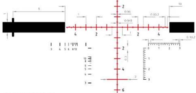
Alle Made in mind / All dimensions In mind
MR5
MINOX ZP5 5-25x56
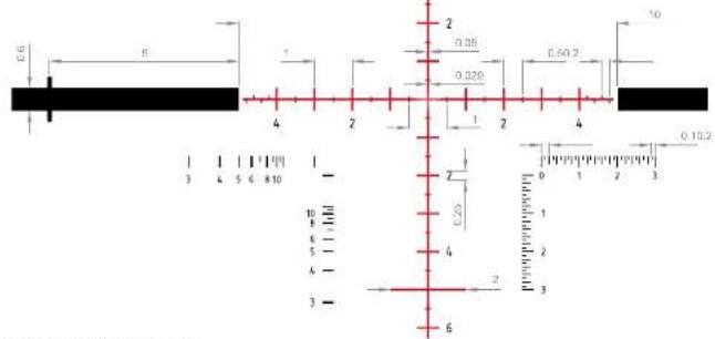
Alle Melle in mind / AI dimensions in mind
Abmessungen · Dimensions [mm]


ZP5 3-15x50 ZP5 5-25x56
Design subject to alterations without notice.
MINOX is a registered trademark of MINOX GmbH, Wetzlar.
MINOX GmbH
Walter-Zapp-Str. 4
D-35578 Wetzlar, Germany
Tel.: +49 (0) 6441 / 917-0
Fax: +49 (0) 6441 / 917-612
E-mail: info@minox.com
Blaser USA
403 East Ramsey, Suite 301
San Antonio, Texas 78216
Tel.: (210)-377-2527
E-mail: minox@blaser-usa.com
www.minox.com
www.minox.com/facebook
www.youtube.com/minoxwebcasts

99555 03/18 fa
- Welcome to MINOX!
- Overview
- Scope of delivery
- Magnification setting
- Diopter adjustment
- Parallax adjustment
- Reticle illumination and battery change
- Reticle adjustment
- Reticle features
- Mrad Scale
- Target size [cm] · scale value = distance [m]
- Lens cap
- Care and maintenance
- Mounting
- Troubleshooting
- Fogging
- Serial number
- Service
- Conditions of Warranty
- Extended MINOX Warranty Service
- MINOX GmbH
Brand : MINOX
Model : ZP5
Category : Binoculars