
MPE-200 - Processor SONY - Free user manual and instructions
Find the device manual for free MPE-200 SONY in PDF.


| Product Type | Multi Image Processor |
| Model | MPE-200 |
| Brand | Sony |
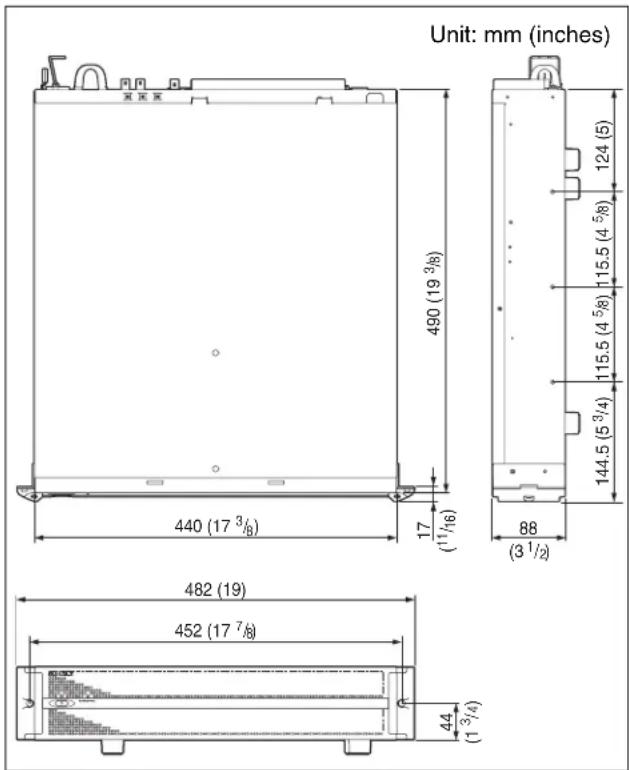
| Dimensions (W x H x D) | 440.0 mm × 88 mm × 490 mm (17 3/8 in. × 3 1/2 in. × 19 3/8 in.) |
| Weight | Approx. 11.5 kg (25 lb 5.6 oz) |
| Power Requirements | AC 100 V to 127 V, 200 V to 240 V, 50/60 Hz |
| Current Consumption | 100-127 V: 4 A, 200-240 V: 2 A |
| Power Consumption | 400 W or less |
| Processor | Cell Broadband Engine (1) |
| Graphics Processor | RSX (1) |
| GPU Local Memory | 256 MB |
| System Memory | XDR + ECC (on board) / 1 GB |
| Sub-Memory | DDR2-333 (on board) / 1 GB |
| Internal Hard Disk Drive | 160 GB (Serial ATA 2.5 in.) |
| Video Inputs | 4 HD-SDI (BNC) |
| Video Outputs | 4 HD-SDI (BNC) |
| Network Ports | 2 x RJ45 (10/100/1000 Base-T) |
| USB Ports | 2 x USB A |
| RS-232C Port | 1 x 9-pin D-sub (male) |
| Reference Input | BNC, 75Ω termination (HD tri-level sync / SD black burst) |
| Operating Temperature | 5 °C to 40 °C (41 °F to 104 °F) |
| Storage Temperature | -20 °C to +60 °C (-4 °F to +140 °F) |
| Operating Humidity | 20% to 90% (no condensation) |
| Rack Mountable | Yes, 2U, 19-inch (optional RMM-10 kit) |
| Maintenance | Clean ventilation holes monthly; wipe cabinet with dry cloth |
Frequently Asked Questions - MPE-200 SONY
User questions about MPE-200 SONY
0 question about this device. Answer the ones you know or ask your own.
Ask a new question about this device
Download the instructions for your Processor in PDF format for free! Find your manual MPE-200 - SONY and take your electronic device back in hand. On this page are published all the documents necessary for the use of your device. MPE-200 by SONY.
USER MANUAL MPE-200 SONY
MULTI IMAGE PROCESSOR
MPE-200
OPERATION MANUAL 1st Edition (Revised 1)
Japanese/English
安全のために
To reduce the risk of fire or electric shock, do not expose this apparatus to rain or moisture.
To avoid electrical shock, do not open the cabinet. Refer servicing to qualified personnel only.
THIS APPARATUS MUST BE EARTHED.
AVERTISSEMENT
When installing the unit, incorporate a readily accessible disconnect device in the fixed wiring, or connect the power plug to an easily accessible socket-outlet near the unit. If a fault should occur during operation of the unit, operate the disconnect device to switch the power supply off, or disconnect the power plug.
AVERTISSEMENT
Plug Cap Parallel blade with ground pin (NEMA 5-15P Configuration)
Cord Type SJT, three 14 AWG wires
Length Minimum 1.5m (4 ft. 11 in.), Less than 2.5 m (6 ft. 7 in.)
Rating Minimum 15A, 125V
Using this unit at a voltage other than 120V may require the use of a different line cord or attachment plug, or both. To reduce the risk of fire or electric shock, refer servicing to qualified service personnel.
WARNING: THIS WARNING IS APPLICABLE FOR OTHER COUNTRIES.
- Use the approved Power Cord (3-core mains lead) / Appliance Connector / Plug with earthing-contacts that conforms to the safety regulations of each country if applicable.
- Use the Power Cord (3-core mains lead) / Appliance Connector / Plug conforming to the proper ratings (Voltage, Ampere).
If you have questions on the use of the above Power Cord / Appliance Connector / Plug, please consult a qualified service personnel.
AVERTISSEMENT
For the customers in the U.S.A.
This equipment has been tested and found to comply with the limits for a Class A digital device, pursuant to Part 15 of the FCC Rules. These limits are designed to provide reasonable protection against harmful interference when the equipment is operated in a commercial environment. This equipment generates, uses, and can radiate radio frequency energy and, if not installed and used in accordance with the instruction manual, may cause harmful interference to radio communications. Operation of this equipment in a residential area is likely to cause harmful interference in which case the user will be required to correct the interference at his own expense.
You are cautioned that any changes or modifications not expressly approved in this manual could void your authority to operate this equipment.
All interface cables used to connect peripherals must be shielded in order to comply with the limits for a digital device pursuant to Subpart B of Part 15 of FCC Rules.
This device complies with Part 15 of the FCC Rules. Operation is subject to the following two conditions: (1) this device may not cause harmful interference, and (2) this device must accept any interference received, including interference that may cause undesired operation.
For customers in Canada
This Class A digital apparatus complies with Canadian ICES-003.
For the customers in Europe
This product with the CE marking complies with the EMC Directive issued by the Commission of the European Community.
Compliance with this directive implies conformity to the following European standards:
• EN55103-1: Electromagnetic Interference(Emission)
• EN55103-2: Electromagnetic Susceptibility(Immunity)
This product is intended for use in the following Electromagnetic Environment: E4 (controlled EMC environment, ex. TV studio).
For the customers in Europe, Australia and New Zealand
WARNING
This is a Class A product. In a domestic environment, this product may cause radio interference in which case the user may be required to take adequate measures.
For the customers in Europe
The manufacturer of this product is Sony Corporation, 1-7-1 Konan, Minato-ku, Tokyo, Japan. The Authorized Representative for EMC and product safety is Sony Deutschland GmbH, Hedelfinger Strasse 61, 70327 Stuttgart, Germany.
This apparatus shall not be used in the residential area.
For the State of California, USA only
Perchlorate Material - special handling may apply, See www.dtsc.ca.gov/hazardouswaste/perchlorate Perchlorate Material : Lithium battery contains perchlorate.
For the customers in Taiwan only

廢電池請回收
Table of Contents
Usage Notes ......20
Precautions for Products With Built-In HDD.... 20
Ensuring Good Performance From This Unit.... 20
Introduction ......21
Features.... 21
Optional Accessories (Not Supplied) 21
System Configuration Examples....22
Names and Functions of Parts ....23
Front....23
Rear....24
Unit Operations ......25
Maintenance ....26
Troubleshooting 26
Specifications....27
Usage Notes
Precautions for Products With Built-In HDD
This unit has a built-in hard disk drive (HDD). The HDD is a precision device. If subject to shock, vibration, static electricity, high temperature or humidity, data loss can occur. When installing and using the unit, closely observe the following precautions.
Protect from shocks and vibrations
When subject to shocks or vibrations, the HDD can be damaged and loss of data on the HDD can occur.
- When transporting the unit, use the specified packing material. When transporting on a dolly or similar, use a type which does not transmit excessive vibrations. Excessive shocks and vibrations can damage the HDD. Also before removing or inserting the unit in a rack, make sure that power is off.
- Before removing or inserting the unit in a rack, make sure that power to any other HDD-equipped devices in the rack is also switched off.
- Never move the unit while it is powered.
- When placing the unit on a floor or other surface, make sure to put the unit down carefully.
- Do not place the unit near other devices that may become a source of vibrations.
Wait for 30 seconds after turning power off
For a brief interval after the power is turned off, the platters inside the HDD will still keep spinning and the heads will be in an insecure position. During this interval, the unit is more susceptible to shocks and vibrations than during normal operation. For a period of at least 30 seconds after turning power off, avoid subjecting the unit even to very light shocks. After this period, the hard disk will be fully stopped and the unit can be manipulated.
Temperature and humidity related precautions
Use and store the unit only in locations where the specified temperature and humidity ranges are not exceeded.
Temperature range for operation:
$$ 5 ^ {\circ} \mathrm{C} \text { to } 4 0 ^ {\circ} \mathrm{C} (4 1 ^ {\circ} \mathrm{F} \text { to } 1 0 4 ^ {\circ} \mathrm{F}) $$
Performance guaranteed temperature:
$$ 1 0 ^ {\circ} \mathrm{C} \text { to } 3 5 ^ {\circ} \mathrm{C} (5 0 ^ {\circ} \mathrm{F} \text { to } 9 5 ^ {\circ} \mathrm{F}) $$
Humidity range for operation:
$$ 20 \% \text{ to } 90 \% \text{ relative humidity} $$
$$ (\text { no condensation }) $$
Temperature range for storage:
$$ - 2 0 ^ {\circ} \mathrm{C} \text { to } + 6 0 ^ {\circ} \mathrm{C} (- 4 ^ {\circ} \mathrm{F} \text { to } + 1 4 0 ^ {\circ} \mathrm{F}) $$
Humidity range for storage:
$$ 20 \% \text{ to } 90 \% \text{ relative humidity} $$
$$ (\text { no condensation }) $$
Ensuring Good Performance From This Unit
Operation and storage
Avoid using or storing the unit in the following places.
- Where it is subject to extremes of cold or heat (operating temperature 5^ to 40^ (41 °F to 104 °F))
- Where it is subject to direct sunlight for extended periods, or close to heating equipment.
•In conditions of high humidity or much dust
•Where it is subject to severe vibration - Close to a source of strong magnetic fields
- Close to a radio, television, or other source of powerful electromagnetic radiation
Install in a level place
This unit is designed to be operated in a level place. Do not turn it vertically, or incline at an angle of 20 degrees or more.
Do not apply strong shocks
Dropping the unit, or subjecting it to other strong shocks may cause it to break.
Do not obstruct the ventilation holes
To prevent the temperature from rising, do not, for example, wrap the unit in a blanket while operating.
Care of the unit
Clean dirt from the cabinet and panel by wiping gently with a dry cloth. If the unit is very dirty, wipe with a cloth steeped in a little neutral detergent, then wipe dry. Do not use alcohol, thinners, insecticides, or other volatile solvents, as this may cause the case to deform or damage the finish.
Shipping
Pack in the original carton, or similar packaging, to cushion the unit from violent shocks.
Introduction
The MPE-200 is a multi-purpose image processor capable of performing real-time signal processing for HD live image inputs, and outputting images in real time after signal processing.
The unit is equipped with a Cell Broadband Engine (Cell/B.E.) high-performance microprocessor and RSX graphics processor, and is capable of receiving up to four HD image inputs. Signal processing of live images in real time is possible via a software application.
Features
High-performance multicore processor -Cell/B.E.-
The interconnection of the Cell Broadband Engine's internal PPE (PowerPC Processor Element) and eight SPEs (Synergistic Processor Elements) via a high-speed bus, and the ability to connect to external main memory, allow high-performance processing of floating-point operations at 230 GFLOPS.
Graphics engine tightly coupled to Cell/B.E. - RSX -
The RSX graphics processor is connected to the Cell/B.E. via the high-speed FlexIO bus, and delivers efficient graphics processing. With input and output functions at a total of over 4 GB/s, signal processing can be performed simultaneously on four HD lines.
Multiple software installation
The unit supports installation of multiple application software. You can decide which software to install and switch between their use based on your intended purpose.
HD-SDI video input and output
The unit is equipped with video input and output functions for up to four lines via HD-SDI. Utilizing the broadband input and output capabilities of the RSX, the unit can input and output up to 4 lines of HD live images in real time.
Compact 2U (unit) size with 19-inch rack mountability
The unit can be installed on an EIA-standard, universal pitch 19-inch rack. An optional (not supplied) rack mount kit is also available.
Low energy consumption
The unit delivers high computational performance while maintaining low power consumption at 400 W or less.
Optional Accessories (Not Supplied)
The following optional accessories are commercially available.
Application software
A variety of application software is available for installation and use on the unit.
For details, consult your Sony service representative or dealer.
RMM-10 Rack Mount Kit
Rail kit for mounting the unit on a rack.
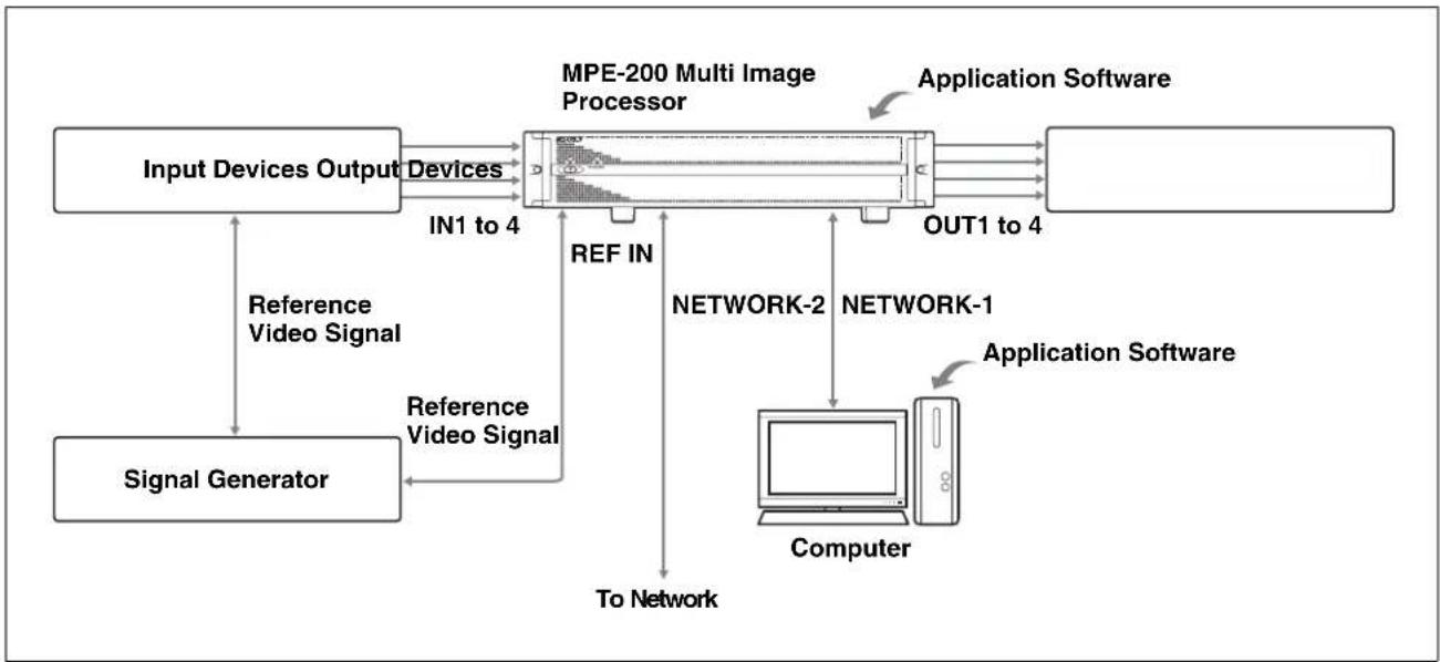
System Configuration Examples
The devices that can be connected to this unit and the supported video formats differ depending on the application software used.
For details, see the User's Guide or Help that is supplied with the application software.
flowchart
graph TD
    A["Input Devices Output"] -->|IN1 to 4| B["MPE-200 Multi Image Processor"]
    C["Signal Generator"] -->|Reference Video Signal| B
    B -->|REF IN| D["NETWORK-2"]
    B -->|OUT1 to 4| E["Application Software"]
    F["Computer"] -->|To Network| B
    G["Application Software"] -->|Application Software| E
Names and Functions of Parts
Front
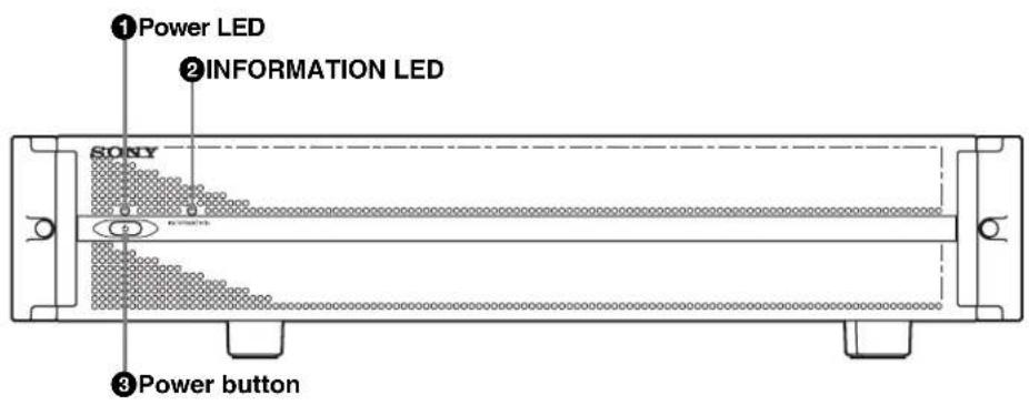
①Power LED
Lights green when the unit is operating normally. This LED, in combination with the INFORMATION LED, indicates the status of the system.
②INFORMATION LED
Lights blue when the unit is operating normally. This LED, in combination with the power LED, indicates the status of the system.
| Power LED IMFORMATIONLED | Status |
| Lit (green) Lit (blue) Operation normal | |
| Lit (green) Off Firmware starting up | or shutting down |
| Blinking (green) Off Unit starting up | |
| Lit (red) Off Standby status | |
| Blinking (red) Off Unit shutting down | |
| Off Off Power not supplied | |
③Power button
When you press this button during standby status, the unit starts up.
When you press and hold this button for one to two seconds while the unit is powered, the INFORMATION LED turns off and the unit begins shutting down. Do not disconnect the power supply until the power LED remains lit in red (standby status).
Press and hold this button for five seconds or more to force shutdown.
CAUTION
When forced shutdown is performed, configuration data on the unit may not be saved.
Rear
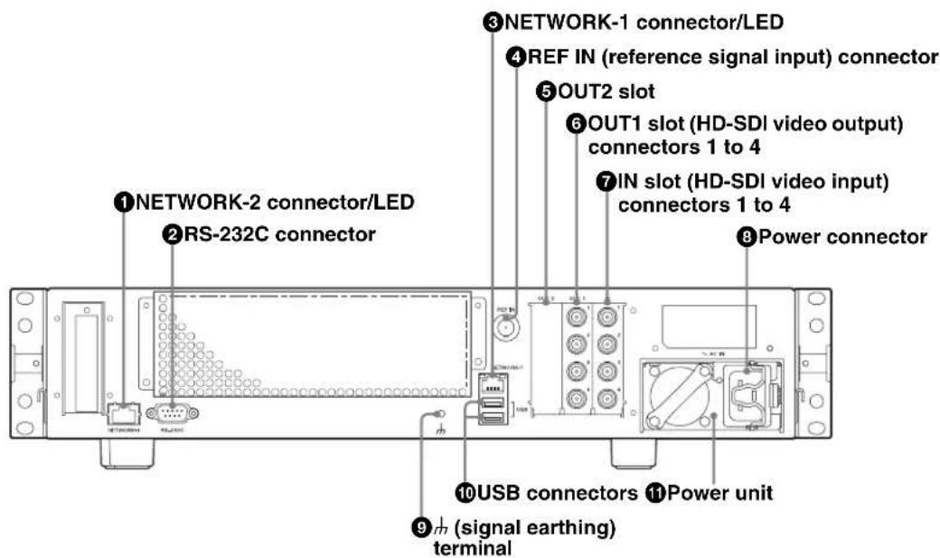
①NETWORK-2 connector/LED
Supports 10 Base-T, 100 Base-TX, and 1000 Base-T Ethernet.
| Right LED Transmission speed | |
| Off Not 1000 Base | |
| Lit (green) 1000 Base | |
| Left LED Transmission status | |
| Off Not linked | |
| Lit (orange) Linked | |
| Blinking (orange) Transmission in progress | |
②RS-232C connector
Used for maintenance or system administration.
③NETWORK-1 connector/LED
Connects to networks for data transfer. Supports 10 Base-T, 100 Base-TX, and 1000 Base-T Ethernet.
| Right LED Transmission speed | |
| Off Not 1000 Base | |
| Lit (orange) 1000 Base | |
| Left LED Transmission status | |
| Off Not linked | |
| Lit (green) Linked | |
| Lit (red) Transmission in progress | |
④ REF IN (reference signal input) connector
Inputs reference image signals of the specified field frequency. Automatically terminates at 75Ω.
5OUT2 slot
Slot for future option installation.
⑥ OUT1 slot (HD-SDI video output) connectors 1 to 4
Outputs HD-SDI video signals.
⑦IN slot (HD-SDI video input) connectors 1 to 4
Inputs HD-SDI video signals.
⑧Power connector
Connect the power cord here.
To prevent accidental disconnection of the power cord, attach a power cord clamp.
⑨ ^1 (signal earthing) terminal
Connect the earthing wire for the system here.
⑩USB connectors
Connect USB devices here.
⑪ Power unit
Consult your Sony service representative or dealer for maintenance and replacement.
As the power unit produces heat, the internal cooling fan will operate even when the unit is in standby status.
CAUTION
- For safety, do not connect the connector for peripheral device wiring that might have excessive voltage to the following ports.
- NETWORK-1 connector
-NETWORK-2 connector
Follow the instructions for the above ports.
- When you connect the LAN cable of the unit to peripheral device, use a shielded-type cable to prevent malfunction due to radiation noise.
ATTENTION
You can operate the unit by installing application software on the unit and connecting it to a computer and other external devices.
The operation procedures differ depending on the application software that is installed. For details, see the User's Guide or Help that is supplied with the application software.
Maintenance
Remove dust from the ventilation holes once a month or whenever the holes are dirty.
Troubleshooting
Check the following if problems occur. If a problem persists, consult your Sony service representative or dealer.
The unit does not turn on.
- Make sure that the power cord is connected properly.
- Make sure that the power unit is installed properly.
Cannot connect to the network.
- Make sure that the network cable is connected properly.
- Make sure that connections to the NETWORK-1 and NETWORK-2 ports are not mixed up.
The unit overheats quickly.
- Make sure that objects, including dust, are not blocking the ventilation holes.
Specifications
Processor
CPU Cell/B.E. (1)
Cache memory 512 KB (PPU)
CPU clock speed 3.2 GHz
GPU RSX (1)
GPU local memory
256 MB
Memory
System memory XDR + ECC (on board) / 1 GB
Sub-memory DDR2-333 (on board) / 1 GB
Storage device
Internal hard disk drive
160 GB (Serial ATA 2.5 in.)
External connection ports
NETWORK-1, -2
RJ45
10 Base-T/100 Base-TX/1000 Base-T
USB USB A × 2
RS-232C 9-pin D-sub (male) × 1
Data transfer rate: 38.4 Kbps
IN 1 to 4 (HD-SDI input)
BNC × 4, 75Ω
Signal format: SMPTE 292M standard
Signaling rate: 1.5 Gbps
Cable length: 100 m (approx. 328 ft.)
(when using 5C-FB cable (Belden
1694 equivalent))
Video*: 1080/59.94i, 1080/50i,
1080/23.98PsF, 1080/24PsF,
1080/25PsF, 1080/29.97PsF,
720/59.94p, 720/50p
OUT1 1 to 4 (HD-SDI output)
BNC × 4, 75Ω
Signal format: SMPTE 292M standard
Signaling rate: 1.5 Gbps
Video*: 1080/59.94i, 1080/50i,
1080/23.98PsF, 1080/24PsF,
1080/25PsF, 1080/29.97PsF,
720/59.94p, 720/50p
REF IN BNC, 75Ω termination
HD tri-level sync / SD black burst
Tri-level sync is not supported for the
720p format.
*The supported video formats differ depending on the application software used.
General
Power requirements
AC 100 V to 127 V, 200 V to 240 V, 50/60 Hz
Current consumption
100 V to 127 V: 4 A, 200 V to 240 V: 2 A
Peak inrush current
(1) Power ON, current probe method: 10 A (100 V), 28 A (240V)
(2) Hot switching inrush current, measured in accordance with European standard EN55103-1: 12 A (230 V)
Operating temperature
5^ to 40^ (41 °F to 104 °F)
Performance guaranteed temperature
10^ to 35^ (50°F to 95°F)
Storage temperature
-20^ to +60^ (-4^ to +140^)
Operating humidity
20% to 90% (no condensation)
Mass Approx. 11.5 kg (25 lb. 5.6 oz.)
Dimensions 440.0 mm × 88 mm × 490 mm
(17 38 in. × 3 12 in. × 19 38 in.)
(w/h/d, excluding protrusions)
Supplied accessories
Operation Manual (1)
Installation Manual (1)
Notice Concerning Software (1)
Recommended power cord
UC Part number 1-837-564-11
(125 V, 15 A, 2.0 m (6 ft. 8 in.))
Europe Part number 1-837-562-11
(250 V, 16 A, 2.0 m (6 ft. 8 in.))
Design and specifications are subject to change without notice.
Note
Always verify that the unit is operating properly before use. SONY WILL NOT BE LIABLE FOR DAMAGES OF ANY KIND INCLUDING, BUT NOT LIMITED TO, COMPENSATION OR REIMBURSEMENT ON ACCOUNT OF THE LOSS OF PRESENT OR PROSPECTIVE PROFITS DUE TO FAILURE OF THIS UNIT, EITHER DURING THE WARRANTY PERIOD OR AFTER EXPIRATION OF THE WARRANTY, OR FOR ANY OTHER REASON WHATSOEVER.
商標について
"RSX" is trademark of Sony Computer Entertainment Inc.
"FlexIO" is trademark of Rambus Inc.
All other company names and product names mentioned here may be the trademarks or registered trademarks of their respective holders.
The symbols for ^TM and ^ are omitted in this manual.
The material contained in this manual consists of information that is the property of Sony Corporation and is intended solely for use by the purchasers of the equipment described in this manual.
Sony Corporation expressly prohibits the duplication of any portion of this manual or the use thereof for any purpose other than the operation or maintenance of the equipment described in this manual without the express written permission of Sony Corporation.
For Customer in China
Printed on recycled paper.
Printed in Japan
2010.9 32
© 2009
- MULTI IMAGE PROCESSOR
- MPE-200
- 安全のために
- AVERTISSEMENT
- WARNING: THIS WARNING IS APPLICABLE FOR OTHER COUNTRIES.
- For the customers in the U.S.A.
- For customers in Canada
- For the customers in Europe
- For the customers in Europe, Australia and New Zealand
- WARNING
- For the State of California, USA only
- For the customers in Taiwan only
- Table of Contents
- Usage Notes
- Precautions for Products With Built-In HDD
- Protect from shocks and vibrations
- Wait for 30 seconds after turning power off
- Temperature and humidity related precautions
- Ensuring Good Performance From This Unit
- Operation and storage
- Install in a level place
- Do not apply strong shocks
- Do not obstruct the ventilation holes
- Care of the unit
- Shipping
- Introduction
- Features
- High-performance multicore processor -Cell/B.E.-
- Graphics engine tightly coupled to Cell/B.E. - RSX -
- Multiple software installation
- HD-SDI video input and output
- Compact 2U (unit) size with 19-inch rack mountability
- Low energy consumption
- Optional Accessories (Not Supplied)
- Application software
- RMM-10 Rack Mount Kit
- System Configuration Examples
- Names and Functions of Parts
- Front
- ①Power LED
- ②INFORMATION LED
- ③Power button
- CAUTION
- Rear
- ①NETWORK-2 connector/LED
- ②RS-232C connector
- ③NETWORK-1 connector/LED
- ④ REF IN (reference signal input) connector
- 5OUT2 slot
- ⑥ OUT1 slot (HD-SDI video output) connectors 1 to 4
- ⑦IN slot (HD-SDI video input) connectors 1 to 4
- ⑧Power connector
- ⑨ 1 (signal earthing) terminal
- ⑩USB connectors
- ⑪ Power unit
- ATTENTION
- Maintenance
- Troubleshooting
- The unit does not turn on.
- Cannot connect to the network.
- The unit overheats quickly.
- Specifications
- Processor
- Memory
- Storage device
- External connection ports
- General
- Supplied accessories
- Recommended power cord
- Note
Brand : SONY
Model : MPE-200
Category : Processor