
IXS-6700 - Router SONY - Free user manual and instructions
Find the device manual for free IXS-6700 SONY in PDF.


| Product Type | Wireless Router |
| Brand | Sony |
| Model | IXS-6700 |
| Wireless Standards | IEEE 802.11a/b/g/n/ac (dual-band) |
| Frequency Bands | 2.4 GHz and 5 GHz |
| Maximum Data Rate | Up to 1200 Mbps |
| Ports | 4 x Gigabit Ethernet LAN, 1 x Gigabit WAN, 1 x USB 2.0 |
| Antennas | 4 external fixed antennas |
| Security | WPA2, WPA, WEP, SPI Firewall, MAC Filtering |
| Dimensions (W x D x H) | 250 x 180 x 50 mm |
| Weight | 500 g |
| Power Supply | AC 100-240V, 50/60Hz, 15W |
| Power Consumption | 15 W (typical) |
| Operating Temperature | 0°C to 40°C |
| Storage Temperature | -20°C to 70°C |
| LED Indicators | Power, Internet, LAN (4), WLAN, USB |
| Management | Web-based GUI, Sony Network App |
| Features | QoS, Parental Controls, Guest Network, VPN Passthrough, Dynamic DNS |
| Encryption | 128-bit AES, TKIP |
| Recommended Use | Home or small office |
Frequently Asked Questions - IXS-6700 SONY
User questions about IXS-6700 SONY
0 question about this device. Answer the ones you know or ask your own.
Ask a new question about this device
Download the instructions for your Router in PDF format for free! Find your manual IXS-6700 - SONY and take your electronic device back in hand. On this page are published all the documents necessary for the use of your device. IXS-6700 by SONY.
USER MANUAL IXS-6700 SONY
1st Edition (Revised 6)
安全のために
REMOTE 2:RS-422A 信号規格準拠 (S-
BUS コマンドに変換可)
プロトコル:ソニー Cart++
データ転送速度 38.4 Kbps
ALARM: パラレル、オープンコレク
ター 4 出力
SRC ON のとき: 104 μs (5 word) +2.1 ms
V1.1 以上
SRC OFF のとき: 146 μs (7 word)
SRC ON のとき: 146 μs (7 word) +2.1 ms
SRC: Sampling Rate Converter (IKS-A6015)
± 0.2 dB 以内 (AES/EBU 入力)
To reduce the risk of fire or electric shock, do not expose this apparatus to rain or moisture.
To avoid electrical shock, do not open the cabinet. Refer servicing to qualified personnel only.
THIS APPARATUS MUST BE EARTHED.
AVERTISSEMENT
For the customers in the U.S.A.
This equipment has been tested and found to comply with the limits for a Class A digital device, pursuant to Part 15 of the FCC Rules. These limits are designed to provide reasonable protection against harmful interference when the equipment is operated in a commercial environment. This equipment generates, uses, and can radiate radio frequency energy and, if not installed and used in accordance with the instruction manual, may cause harmful interference to radio communications. Operation of this equipment in a residential area is likely to cause harmful interference in which case the user will be required to correct the interference at his own expense.
You are cautioned that any changes or modifications not expressly approved in this manual could void your authority to operate this equipment.
All interface cables used to connect peripherals must be shielded in order to comply with the limits for a digital device pursuant to Subpart B of Part 15 of FCC Rules.
This device complies with Part 15 of the FCC Rules. Operation is subject to the following two conditions: (1) this device may not cause harmful interference, and (2) this device must accept any interference received, including interference that may cause undesired operation.

This symbol is intended to alert the user to the presence of important operating and maintenance (servicing) instructions in the literature accompanying the appliance.
WARNING: THIS WARNING IS APPLICABLE FOR USA ONLY.
If used in USA, use the UL LISTED power cord specified below.
DO NOT USE ANY OTHER POWER CORD.
Plug Cap Parallel blade with ground pin
(NEMA 5-15P Configuration)
Cord Type SJT, three 16 or 18 AWG wires
Length Minimum 1.5 m (4 ft.11 in.), Less than 2.5 m (8 ft. 3 in.)
Rating Minimum 10 A, 125 V
Using this unit at a voltage other than 120 V may require the use of a different line cord or attachment plug, or both.
To reduce the risk of fire or electric shock, refer servicing to qualified service personnel.
WARNING: THIS WARNING IS APPLICABLE FOR OTHER COUNTRIES.
-
Use the approved Power Cord (3-core mains lead) / Appliance Connector / Plug with earthing-contacts that conforms to the safety regulations of each country if applicable.
-
Use the Power Cord (3-core mains lead) / Appliance Connector / Plug conforming to the proper ratings (Voltage, Ampere).
If you have questions on the use of the above Power Cord / Appliance Connector / Plug, please consult a qualified service personnel.
AVERTISSEMENT
For the customers in Canada
This Class A digital apparatus complies with Canadian ICES-003.
For the customers in Europe (IXS-6600/6700 only)
This product with the CE marking complies with both the EMC Directive and the Low Voltage Directive issued by the Commission of the European Community.
Compliance with these directives implies conformity to the following European standards:
• EN60950-1: Product Safety
• EN55103-1: Electromagnetic Interference (Emission)
• EN55103-2: Electromagnetic Susceptibility (Immunity)
This product is intended for use in the following Electromagnetic Environment: E4 (controlled EMC environment, ex. TV studio).
For the customers in Europe (Optional Board only)
This product with the CE marking complies with the EMC Directive issued by the Commission of the European Community.
Compliance with this directive implies conformity to the following European standards:
• EN55103-1: Electromagnetic Interference (Emission)
• EN55103-2: Electromagnetic Susceptibility (Immunity)
This product is intended for use in the following Electromagnetic Environment: E4 (controlled EMC environment, ex. TV studio).
The manufacturer of this product is Sony Corporation, 1-7-1 Konan, Minato-ku, Tokyo, Japan.
The Authorized Representative for EMC and product safety is Sony Deutschland GmbH, Hedelfinger Strasse 61, 70327 Stuttgart, Germany.
This apparatus shall not be used in the residential area.
For the customers in Europe, Australia and New Zealand
WARNING
This is a Class A product. In a domestic environment, this product may cause radio interference in which case the user may be required to take adequate measures. In the case that interference should occur, consult your nearest authorized Sony service facility.
For the Customers in Taiwan only

廢電池請回收
For the State of California, USA only
Perchlorate Material - special handling may apply, See www.dtsc.ca.gov/hazardouswaste/perchlorate Perchlorate Material : Lithium battery contains perchlorate.
Table of Contents
The Integrated Routing System Manual Line-up 47
Overview 47
Features of the IXS-6600/6700 Integrated Routing System.....48
IXS-6600/6700 System Products 49
Configuration Examples....53
Control System of the IXS-6600/6700 Integrated Routing System ....54
Functions of the IXS-6600/6700 Integrated Routing System ...54
Functions of an S-BUS System ....55
System Connection Example....56
Locations and Functions of Parts 58
IXS-6600 Integrated Routing System 58
IXS-6700 Integrated Routing System 61
Option Boards....64
Status Indications 66
Displayed Items 66
Functions of the Operation Buttons....67
Basic Operations....67
Confirming the Status of the Machine....67
Adjusting the Contrast of the Display Window ......67
Error Indications and Countermeasures 68
Status Indicators 68
Error Status 69
Supplied Software.... 71
Installing BZR-21....71
Specifications.... 72
IXS-6700 Integrated Routing System 72
IXS-6600 Integrated Routing System 73
Optional Boards....75
The Integrated Routing System Manual Line-up
The following manuals have been prepared to thoroughly explain this Integrated Routing System. Under the directions provided in this manual and in correlation with your needs, refer to the manual that suits your purpose best.
Operation Manual (this manual, on a supplied CD-ROM)
This manual supplies information related to a simple outline of the integrated routing system, connection examples, an explanation of each part, and the specifications.
System Setup Manual (on a supplied CD-ROM)
This manual supplies information related to the initial settings and verification of operation. It also supplies information about the principal equipment in a integrated routing system.
Installation Manual (on a supplied CD-ROM)
This manual supplies information related to the maintenance and initial service to the integrated routing system such as board replacement.
Maintenance Manual (option)
This manual supplies information related to the servicing of each parts level (i.e. the essential points for adjustment, mount diagrams, circuit diagrams, and a detailed parts list). Ask the Sony dealer where you purchased this integrated routing system for details about obtaining this manual.
Protocol Manual (option)
Supplies information related to the protocol used to control this integrated routing system.
The following manual is available for your reference about the protocol supported by this integrated routing system:
Remote 1 (S-BUS/ROT16) control protocol: REMOTE1 (S-BUS/ROT16) PROTOCOL and COMMAND SPECIFICATIONS
Remote 2 (Cart++) control protocol: REMOTE2 (Cart++) PROTOCOL and COMMAND SPECIFICATIONS
Ask the Sony dealer where you purchased this integrated routing system for details about obtaining these manuals.
Overview
The IXS-6600/6700 Integrated Routing System handles AES/EBU digital audio signals, analog audio signals, digital video (SD and HD) signals, and time code signals as well as data (RS-422A signals).
By mounting various optional boards in the IXS-6600/6700 enclosure model, you can configure it to handle a wide array of signals.
For details, see "IXS-6600/6700 System Products" on page 49.
Actual signal switching can be controlled, using an external control unit, such as the optional BKS-R1617/R1617A/R1618/R3216/R3219/R3219A/R3220/R6010 Routing Switcher Control Unit.
For details, see “Control System of the IXS-6600/6700 Integrated Routing System” on page 54.
Some of signal-switching operations can be controlled from a PC if the BZR-21 Routing Switcher Remote Control Software (supplied) is installed on the PC connected with the IXS-6600/6700, using Ethernet or RS-232C.
For details, see "Supplied Software" on page 71.
To operate this system, various settings (table data creation and system settings) must be made beforehand, using terminal emulator software on the PC.
For details, refer to the System Setup Manual (supplied).
Notes
- For the HDTV SDI signal line, use the HD/SD-type optional boards from input through output, as shown below:
Processor board: IKS-V6050M
Input board: IKS-V6010M
Output board: IKS-V6060M
- For example, even if the HD/SD Digital Video Output Board is used for output, when a processor board dedicated to the SDTV SDI signals (SD Video Router Processor) is used for processing, HDTV SDI signals are not output.
- When the RS-422 boards are to be mounted, the slot number for the IKS-RS6010 Input Board and that for the IKS-RS6060 Output Board must be identical, as they are handled as a pair. For example, if the input board is installed in Slot 3 for input boards, the output board must be also installed in Slot 3 for output boards.
- The 540 Mbps SDTV SDI signal is not handled by the SD Digital Video Board. Only a digital video board that can handle HD/SD signals can support this signal.
For details, refer to the Installation Manual (supplied).
Features of the IXS-6600/6700 Integrated Routing System
Selectable two types of chassis
For the IXS-6700, when digital video signals are handled, from a minimum of 16 inputs × 17 outputs to a maximum of 128 inputs × 136 outputs can be installed in an EIA 8RU chassis. For the IXS-6600, a minimum of 16 inputs × 17 outputs to a maximum of 64 inputs × 68 outputs can be installed in an EIA 4RU chassis.
Multiple signal formats handled in a single chassis
The IXS-6600/ 6700 can handle the following signals:
• Video: HDTV SDI signal
• Video: SDTV SDI signal
• Audio: Analog audio signals, AES/EBU digital audio signal
• Data: RS-422A signal
• Time code: LTC signal
Multiple signal-format boards can be mounted in a single chassis for simultaneous operation, which enables reducing the number of devices required for routing to one.
Flexible input/output configuration
The video signals can be expanded in units of 16 inputs and 17 outputs.
The digital audio (balanced) signals can be expanded in units of 32 inputs and 34 outputs.
The digital audio (unbalanced) signals and time code (LTC) signals can be expanded in units of 16 inputs and 17 outputs.
The analog audio (balanced) signals can be expanded in units of 8 stereo inputs and outputs.
Data signals can be expanded in units of 7 inputs and 7 outputs, as 7 inputs and 7 outputs are handled as a pair. The input digital audio signals can be converted to analog audio signals and be supplied, and also the input analog audio signals can be converted to digital audio signal and be supplied.
Note
The Dolby-E signal input to the AES/EBU input board cannot be supplied as an analog audio signal.
Multiple-bit-rate video signals supported
With the use of optional boards supporting multiple-bit-rate video signals, SDTV SDI signals (143 Mbps, 177 Mbps, 270 Mbps, 360 Mbps, 540 Mbps), HDTV SDI signals (1.485 Gbps, 1.485/1.001 Gbps), and DVB-ASI 270 Mbps signals can be handled. These rates can be independently selected for each input/output.
Supporting audio asynchronous system
If an SRC (Sampling Rate Converter) board is mounted, asynchronous digital audio input signals can be supported.
Audio matrix size double that for video signals
The TDM (Time Division Multiplexing) technique enables matrix size (256 × 272) for the AES/EBU digital audio signals (balanced) double that for video signals.
Supporting Dolby E (compressed audio)
Linear PCM audio functions supported
- Soft Switching (V1.10 or later)
Slow transition of audio data toward 0 at a switching point reduces popping and clicking sounds in the audio output.
Note
Soft Switching does not support Dolby E.
- SRC (Sampling Rate Converter) ON/OFF function
Activation/deactivation of the Sampling Rate Converter function can be set for each AES/EBU digital audio input signal.
For details, refer to the System Setup Manual (supplied).
- SRC (Sampling Rate Converter) Matched Phase Mode
A phase difference between adjacent channels can be maintained for the audio signals input to the Sampling Rate Converter.
Note
This function is effective for audio channels on a single input board, but not for audio channels on multiple input boards.
For details, refer to the System Setup Manual (supplied).
• A variety of audio 2-channel outputs
The audio signals have stereo channels, and audio sources for those two channels can be output in the following four manners in addition to stereo (default): Lboth, Rboth, Swap, and Mix(L+R). (V1.10 or later)
Note
For the ancillary data for the AES/EBU format signals (channel status, user data, and validity flag), Lboth, Rboth, Swap, and Mix(L+R) do not function.
Linear PCM/Compressed audio functions supported
- Channel status regeneration (V1.10 or later)
When AES/EBU signals are switched, a CRC (Cyclic Redundancy Check) error may be generated in the device to which the signal from this unit is input, because
the data within the block become inconsistent with the CRC values. To prevent muting caused by such a CRC error, regeneration of channel status is performed.
Supporting RS-422A physical assignment
Redundant CPU/redundant power units as standard equipment
The control board and power units for backups, which are essential for highly reliable professional broadcasting equipment, are provided as standard equipment.
Two Ethernet connectors for two networks
Two Ethernet connectors are provided for one chassis of the IXS-6600/6700, and a different IP address is assigned to each of them, enabling redundancy of two networks.
Web settings (V2.0 or higher)
Settings for the primary station and secondary stations are enabled from the Web browser.
Applicable devices
Primary station: IXS-6600/IXS-6700 (V2.0 or higher)
Secondary Station: IXS-6600/IXS-6700 (V2.0 or higher), HDS-X5800
(Applicable browser: Internet Explorer 6)
For details, refer to the System Setup Manual supplied.
Equipped with two reference-signal systems
The IXS-6600/6700 is equipped with two reference systems A and B for the video reference input, which can be selected for each output block. For example, the house sync of a broadcast station and a reference signal that has a different phase/frequency from that of the house sync can be used in a single chassis as the references for different matrixes.
Supporting the word sync signal
The IXS-6700 is provided with two systems of the audio word sync signal input, and the IXS-6600 is provided with one.
Provided with three systems of the S-BUS control
The IXS-6700 is provided with independent three systems and four channels (A, B1, B2, C) of the S-BUS connectors, and the IXS-6600 is provided with independent three systems and three channels (A, B, C) of the S-BUS connectors. In each S-BUS control system, all routing switchers and control units that are to be controlled are connected using one coaxial cable.
Supporting BZR-IF830 (4093 × 4093) Control Software
S-BUS space can be expanded up to 4093 × 4093 , by connecting the HKSP-R80 Routing Switcher Controller for which BZR-IF830 has been installed to this unit through the Ethernet and S-BUS data link. Within the expanded S-BUS space, several S-BUS spaces can be controlled.
IXS-6600/6700 System Products
Chassis
IXS-6700 Integrated Routing System
The size of the chassis of the IXS-6700 is EIA 8RU. The maximum matrix size for a single-format signal is as shown in the table below:
| Signal Maximum matrix size | |
| Video 128 inputs × 136 outputs | |
| AES/EBU digital audio (balanced) | 256 inputs × 272 outputs |
| AES/EBU digital audio (unbalanced) | 128 inputs × 136 outputs |
| Analog audio (balanced) | 4 stereo inputs × 64 stereo outputs |
| Time code (unbalanced) | 128 inputs × 136 outputs |
| RS-422A 112 ports | |
The unit essentially consists of four power units and two control CPU boards, both having redundant structure. The optional boards described later can be attached.
IXS-6600 Integrated Routing System
The size of the chassis of the IXS-6600 is EIA 4RU. The maximum matrix size for a single-format signal is as shown in the following table below:
| Signal Maximum matrix size | |
| Video 64 inputs × 68 outputs | |
| AES/EBU digital audio (balanced) | 128 inputs × 136 outputs |
| AES/EBU digital audio (unbalanced) | 64 inputs × 68 outputs |
| Analog audio (balanced) | 32 stereo inputs × 32 stereo outputs |
| Time code (unbalanced) | 64 inputs × 68 outputs |
| RS-422A 56 ports | |
The unit essentially consists of two power units and two control CPU boards, both having redundant structure. The optional boards described later can be attached.
Matrix boards (option)
IKS-6030M Matrix Board
This is a matrix board of 128 inputs × 68 outputs.
Up to two matrix boards can be attached to the IXS-6700, with maximum expansion to 128 inputs × 136 outputs possible. When this board is attached to the IXS-6600, the matrix size becomes 64 inputs × 68 outputs.
When audio signals are handled, the maximum matrix size becomes 256 inputs × 272 outputs for the IXS-6700 or 128 inputs × 136 outputs for the IXS-6600.
| Model name of optional board | Product name | Maximum quantity to mount | |
| IXS-6600 IXS-6700 | |||
| IKS-6030M Matrix Board 1 2 | |||
Main Processor Board (option)
The following three main processor boards can be mounted in combination:
• IKS-V6050M HD/SD Video Router Processor Board
• IKS-V6050SD SD Video Router Processor Board
• IKS-A6050 Audio/Data Router Processor Board
| Model name of optional board | Product name | Maximum quantity to mount | |
| IXS-6600 | IXS-6700 | ||
| IKS-V6050M HD | D/SD Video Router Processor Board | 2 | 4 |
| IKS-V6050SD | SD Video Router Processor Board | ||
| IKS-A6050 Audio/Data Router Processor Board | |||
IKS-V6050M HD/SD Video Router Processor Board
This is a router processor board that handles 34 HD/SD digital video signals. It can handle SDTV SDI signal rates (143 Mbps, 177 Mbps, 270 Mbps, 360 Mbps, 540 Mbps), HDTV SDI signal rates (1.485 Gbps, 1.485/1.001 Gbps), and DVB-ASI 270 Mbps signals.
At the later stage of one HD/SD video router processor board, up to two output boards can be attached. When four HD/SD Video Router Processor Boards are attached to the IXS-6700, 136 video signals can be output. When two HD/SD Video Router Processor Boards are attached to the IXS-6600, 68 video signals can be output. For output boards, HD/SD Digital Video Output Boards, SD Digital Video Output Boards, and Time Code Output Boards can be used in combination.
Note
The HD/SD Digital Video Output Board is required in order to obtain HDTV SDI signal output.
IKS-V6050SD SD Video Router Processor Board
This is a router processor board that handles 34 SD digital video signals. It can handle SDTV SDI signal rates (143 Mbps, 177 Mbps, 270 Mbps, 360 Mbps) and DVB-ASI 270 Mbps signals.
At the later stage of one SD Video Router Processor Board, up to two output boards for digital video signals or time code signals can be attached.
When four SD Video Router Processor Boards are attached to the IXS-6700, 136 video signals can be output. When two SD Video Router Processor Boards are attached to the IXS-6600, 68 video signals can be output.
Note
HDTV SDI signal output cannot be obtained even if the HD/SD Digital Video Output Board is attached.
IKS-A6050 Audio/Data Router Processor Board
This is a router processor board that handles 68 AES/EBU audio signals, 16 stereo analog audio signals, 28 data signals (RS-422A), and 34 time code signals.
At the later stage of one Audio/Data Router Processor Board, up to two output boards can be attached. For output boards, AES/EBU Audio Output Boards, Analog Audio Output Boards, RS-422A Output Boards, and Time Code Output Boards can be used in combination.
Input Boards (option)
| Model name of optional board | Product name | Maximum quantity to mount | |
| IXS-6600 | IXS-6700 | ||
| IKS-V6010M 16 | HD/SD Digital Video Input Board | 4 | 8 |
| IKS-V6010SD | 16 SD Digital Video Input Board | ||
| IKS-A6011 32 | D-sub AES/EBU (balanced) Input Board | ||
| IKS-A6012 16 | BNC AES/EBU (unbalanced) Input Board | ||
| IKS-A6013 Anal | log Audio Input Board | ||
| IKS-A6015 32 | Sampling Rate Converter Board | ||
| IKS-RS6010 7 | RS-422 Input Board | ||
| IKS-TC6010 16 | Time Code Input Board | ||
IKS-V6010M 16 HD/SD Digital Video Input Board
This is an input board that handles 16 HD/SD digital video signals. The input connectors can support SDTV SDI signal rates (143 Mbps, 177 Mbps, 270 Mbps, 360 Mbps, 540 Mbps), HDTV SDI signal rates (1.485 Gbps, 1.485/1.001 Gbps), and DVB-ASI 270 Mbps signals.
For the IXS-6700, the number of inputs can be expanded from 16 to 128, in units of 16.
For the IXS-6600, the number of inputs can be expanded from 16 to 64, in units of 16.
IKS-V6010SD 16 SD Digital Video Input Board
This is an input board that handles 16 SD digital video signals. The input connectors can support SDTV SDI signal rates (143 Mbps, 177 Mbps, 270 Mbps, 360 Mbps) and DVB-ASI 270 Mbps signals.
For the IXS-6700, the number of inputs can be expanded from 16 to 128, in units of 16.
For the IXS-6600, the number of inputs can be expanded from 16 to 64, in units of 16.
Note
The IKS-V6010SD does not support a 540-Mbps SDTV SDI signal rate.
IKS-A6011 32 D-sub AES/EBU Input Board
This is an input board that handles 32 AES/EBU audio (balanced) signals. It supports 48-kHz sampling frequency synchronized with the reference word sync signal of this unit.
For the IXS-6700, the number of inputs can be expanded from 32 to 256, in units of 32.
For the IXS-6600, the number of inputs can be expanded from 32 to 128, in units of 32.
Note
The AES/EBU Digital Audio Input Board does not support asynchronous AES/EBU signals. To handle asynchronous AES/EBU signals, attach the IKS-A6015 32 Sampling Rate Converter Board on this board.
IKS-A6012 16 BNC AES/EBU Input Board
This is an input board that handles 16 AES/EBU audio (unbalanced) signals. It supports 48-kHz sampling frequency synchronized with the reference word sync signal of this unit.
For the IXS-6700, the number of inputs can be expanded from 16 to 128, in units of 16.
For the IXS-6600, the number of inputs can be expanded from 16 to 64, in units of 16.
Note
The AES/EBU Digital Audio Input Board does not support asynchronous AES/EBU signals. To handle asynchronous AES/EBU signals, attach the IKS-A6015 32 Sampling Rate Converter Board on this board.
IKS-A6013 Analog Audio Input Board
This is an input board that handles 8-stereo analog audio (balanced) signals.
For the IXS-6700, the number of inputs can be expanded from 8 to 64, in units of 8 stereo inputs.
For the IXS-6600, the number of inputs can be expanded from 8 to 32, in units of 8 stereo inputs.
Note
The signals are switched in pairs of stereo.
IKS-A6015 32 Sampling Rate Converter Board
This is a board that handles 32 sampling rate conversion. Attaching this board on the IKS-A6011 32 D-sub AES/EBU Input Board or IKS-A6012 16 BNC AES/EBU Input Board enables handling of asynchronous digital input signals.
IKS-RS6010 7 RS-422 Input Board
This is an input board that handles 7 data (RS-422A). It only supports a 38.4-kbps signal rate. As the RS-422 input and output boards are handled as a pair, the input/output size can be expanded in units of 7 inputs and 7 outputs. The maximum number of RS-422 ports for the IXS-6700 is 112, and that for the IXS-6600 is 56.
Note
Use the RS-422 Input and Output Boards as a pair. When the RS-422 boards (IKS-RS6010 Input Board and IKS-RS6060 Output Board) are to be installed, the slot number for the input board and that for the output board must be identical. For example, if the input board is installed in Slot 3 for input boards, the output board must be also installed in Slot 3 for output boards.
For details, refer to the Installation Manual (supplied).
IKS-TC6010 16 Time Code Input Board
This is an input board that handles 16 time code (LTC) signals.
For the IXS-6700, the number of inputs can be expanded from 16 to 128, in units of 16.
For the IXS-6600, the number of inputs can be expanded from 16 to 64, in units of 16.
Output Board (option)
| Model name of optional board | Product name | Maximum quantity to mount | |
| IXS-6600 | IXS-6700 | ||
| IKS-V6060M 17 | HD/SD Digital Video Output Board | 4 | 8 |
| IKS-V6060SD 17 | SD Digital Video Output Board | ||
| IKS-A6061 34 | D-sub AES/EBU (balanced) Output Board | ||
| IKS-A6062 17 | BNC AES/EBU (unbalanced) Output Board | ||
| IKS-A6063 Anal | log Audio Output Board | ||
| IKS-RS6060 7 | RS-422 Output Board | ||
| IKS-TC6060 17 | Time Code Output Board | ||
IKS-V6060M 17 HD/SD Digital Video Output Board
This is an output board that handles 17 HD/SD digital video signals. It supports SDTV SDI signal rates (143
Mbps, 177 Mbps, 270 Mbps, 360 Mbps, 540 Mbps),
HDTV SDI signal rates (1.485 Gbps, 1.485/1.001 Gbps), and DVB-ASI 270 Mbps signals.
For the IXS-6700, the number of outputs can be expanded from 17 to 136, in units of 17.
For the IXS-6600, the number of outputs can be expanded from 17 to 68, in units of 17.
IKS-V6060SD 17 SD Digital Video Output Board
This is an output board that handles 17 SD digital video signals. It supports SDTV SDI signal rates (143 Mbps, 177 Mbps, 270 Mbps, 360 Mbps) and DVB-ASI 270 Mbps signals.
For the IXS-6700, the number of outputs can be expanded from 17 to 136, in units of 17.
For the IXS-6600, the number of outputs can be expanded from 17 to 68, in units of 17.
Note
The IKS-V6060SD does not support a 540-Mbps SDTV SDI signal rate.
IKS-A6061 34 D-sub AES/EBU Output Board
This is an output board that handles 34 AES/EBU audio signals (balanced). It supports 48-kHz sampling frequency synchronized with the reference word sync signal.
For the IXS-6700, the number of outputs can be expanded from 34 to 272, in units of 34.
For the IXS-6600, the number of outputs can be expanded from 34 to 136, in units of 34.
IKS-A6062 17 BNC AES/EBU Output Board
This is an output board that handles 17 AES/EBU audio signals (unbalanced). It supports 48-kHz sampling frequency synchronized with the reference word sync signal.
For the IXS-6700, the number of outputs can be expanded from 17 to 136, in units of 17.
For the IXS-6600, the number of outputs can be expanded from 17 to 68, in units of 17.
IKS-A6063 Analog Audio Output Board
This is an output board that handles 8-stereo analog audio (balanced) signals.
For the IXS-6700, the number of outputs can be expanded from 8 to 64, in units of 8 stereo outputs.
For the IXS-6600, the number of outputs can be expanded from 8 to 32, in units of 8 stereo outputs.
Notes
- The signals are switched in pairs of stereo.
- This board cannot supply Dolby-E input to the AES/EBU input board.
IKS-RS6060 7 RS-422 Output Board
This is an output board that handles 7 data (RS-422A). It only supports a 38.4-kbps signal rate. As the RS-422 input and output boards are handled as a pair, the input/output size can be expanded in units of 7 inputs and 7 outputs.
The maximum number of RS-422 ports for the IXS-6700 is 112, and that for the IXS-6600 is 56.
Note
Use the RS-422 Input and Output Boards as a pair. When the RS-422 boards (IKS-RS6010 Input Board and IKS-RS6060 Output Board) are to be installed, the slot number for the input board and that for the output board must be identical. For example, if the input board is installed in Slot 3 for input boards, the output board must be also installed in Slot 3 for output boards.
For details, refer to the Installation Manual (supplied).
IKS-TC6060 17 Time Code Output Board
This is an output board that handles 17 time code (LTC) signals.
For the IXS-6700, the number of inputs can be expanded from 17 to 136, in units of 17.
For the IXS-6600, the number of inputs can be expanded from 17 to 68, in units of 17.
This board can be used with any processor board of IKS-A6050, IKS-V6050M, or IKS-V6050SD.
Configuration Examples
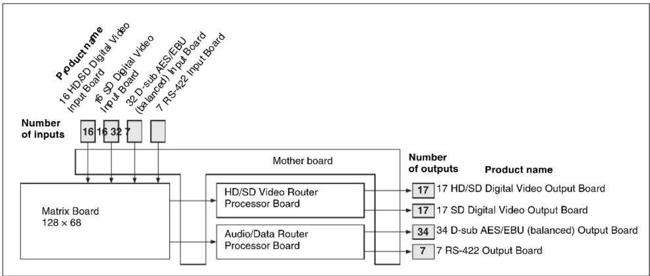
Hybrid configuration examples for the IXS-6600
flowchart
graph TD
    A["Product name"] --> B["16 HD/SD Digital Video"]
    A --> C["16 SD Digital Video"]
    A --> D["16 SD Digital Video"]
    A --> E["32 D-sub AES/EBU (balanced) Input Board"]
    A --> F["7 RS-422 Input Board"]
    G["Number of inputs"] --> H["Matrix Board 128 × 68"]
    H --> I["HD/SD Video Router Processor Board"]
    H --> J["Audio/Data Router Processor Board"]
    I --> K["Number of outputs"]
    J --> L["Number of outputs"]
    K --> M["17 HD/SD Digital Video Output Board"]
    K --> N["17 SD Digital Video Output Board"]
    L --> O["34 D-sub AES/EBU (balanced) Output Board"]
    L --> P["7 RS-422 Output Board"]
With the above configuration, several routing switchers, each of which can handle a different signal format, can be configured within a single chassis enclosure.
The crosspoint size for each signal format is as follows:
| Signal format Matrix size | |
| SDI router section 32 × 34 | (of which, 16 × 17 for HD SDI) |
| Digital audio router section | 32 × 34 |
| RS-422A router section 14 | ports |
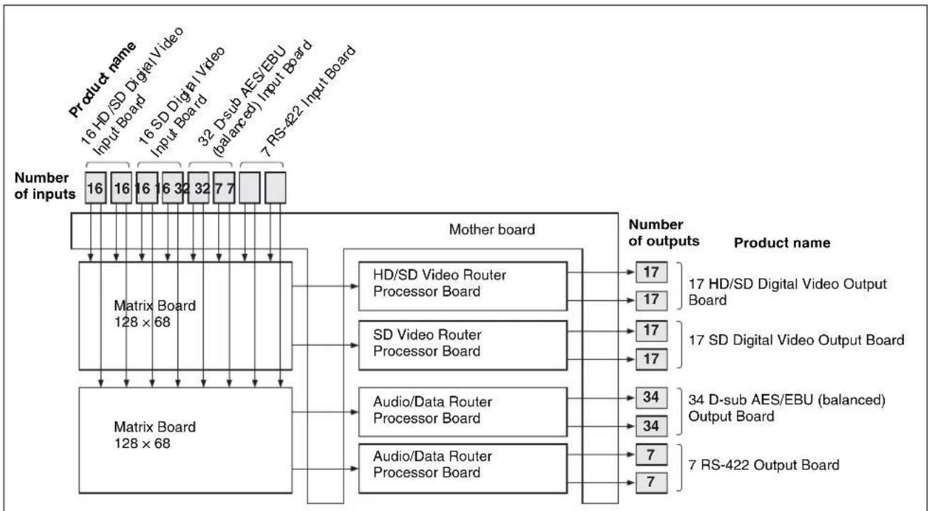
Hybrid configuration examples for the IXS-6700
flowchart
graph TD
    A["Product name"] --> B["16 HD/SD Digital Video Input Board"]
    A --> C["16 SD Digital Video Input Board"]
    A --> D["32 D-sub AES/EBU (balanced) Input Board"]
    A --> E["7 RS-422 Input Board"]
    F["Number of inputs"] --> G["Matrix Board 128 × 68"]
    G --> H["Matrix Board 128 × 68"]
    H --> I["HD/SD Video Router Processor Board"]
    H --> J["SD Video Router Processor Board"]
    H --> K["Audio/Data Router Processor Board"]
    H --> L["Audio/Data Router Processor Board"]
    I --> M["17 HD/SD Digital Video Output Board"]
    J --> N["17 SD Digital Video Output Board"]
    K --> O["34 D-sub AES/EBU (balanced) Output Board"]
    L --> P["7 RS-422 Output Board"]
    M --> Q["Number of outputs"]
    N --> Q
    O --> Q
    P --> Q
With the configuration mentioned before, several routing switchers, each of which can handle a different signal format, can be configured within a single chassis enclosure.
The crosspoint size for each signal format is as shown below:
| Signal format Matrix size | |
| SDI router section 64 × 68 (of which, 16 × 17 for HD SDI) | |
| Digital audio router section 64 × 68 | |
| RS-422A router section 28 ports | |
Control System of the IXS-6600/6700 Integrated Routing System
In the IXS-6600/6700 Integrated Routing System, a remote control panel (routing switcher control unit) controls the signal switching in accordance with the settings of a terminal emulator on a PC. A supplied BZR-21 Routing Switcher Remote Control Software (GUI software) can control basic crosspoint switching on a PC. There are four types of control available for you to control the routing system: S-BUS protocol, which is used through the BNC-type REMOTE 1 connectors; RS-422A protocol, which is used through the D-sub 9-pin REMOTE 2 connectors; RS-232C protocol, which is used through the D-sub 9-pin REMOTE 3 connector; and Ethernet protocol, which is used through the NETWORK connectors. Simultaneous use of four protocols is also possible.
Control using S-BUS protocol
S-BUS is a protocol developed by Sony for control of a digital routing switcher system. This protocol enables communication between multiple routing switchers and remote control panels (routing switcher control units) using one coaxial cable. A combined total of 254 routing switchers, remote control panels and equivalent devices can be controlled using S-BUS protocol. The IXS-6600/6700 has the capability to convert RS-422A commands to S-BUS commands, enabling S-BUS control through the D-sub 9-pin REMOTE 2 connector.
Control using RS-422A protocol
The IXS-6600/6700 has the capability to convert RS-422A commands to S-BUS commands, enabling S-BUS control from the D-sub 9-pin REMOTE 2 connector. The mode that controls signals in their original form using RS-422A commands is known as Direct mode, and the mode that converts RS-422A commands to S-BUS commands is known as S-BUS Convert mode. S-BUS convert mode can control up to 1024 lines, eight levels, however the response speed is slower than in Direct mode. Also, the items that can be controlled in S-BUS Convert mode are limited to those that can be controlled in Direct mode.
When S-BUS remote is set to the primary station, the mode is fixed to S-BUS Convert mode. When set to the secondary station, it is fixed to Direct mode.
Simultaneous control of multiple signals with the level setting
To simultaneously handle several types of signals, each type of signal requires a different routing switcher. These are known as levels. For example, a VTR requires video, audio, time code, and remote control signals for recording. To switch these signals, these signals require video, audio, time code, and remote routing switchers respectively. You can set a maximum of sixteen levels and different input signal numbers on each level in order to simultaneously control these levels.
Functions of the IXS-6600/6700 Integrated Routing System
The IXS-6600/6700 Integrated Routing System is equipped with the following functions:
Designated input and output line protect function
This function prohibits switching of protected output signals from other remote control panels (routing switcher control units) (protect function) and prohibits switching from other control panels by hiding the input signals from all control panels (secret function).
Crosspoint disable function
For every output signal, you can limit the input signals available for selection so that any particular input signals can be output to the specified output lines.
Password function
You can enter a password to prevent unauthorized users from accessing the system.
Name setting function
You can set names for each input and output connector in order to distinguish among the connected signals. Two methods are available for setting the names; either enter the device name and number (i.e. name of the VTR, camera, etc.), for example VTR 1, or a description using up to 16 characters. You can display the name on the optional BKS-R1617/R1618/R3216/R3219/R3220 control units.
Virtual mapping function
You can set crosspoints on a virtual matrix.
Free assignment function
You can assign a different connector number to a connector name on each level.
Tie line function
You can enable the system to automatically select the signal line that connects up to three routing switchers.
Phantom function
You can switch several crosspoints at the same time.
Self-diagnosis function
Information about whether an error has occurred or not can be displayed by the front-panel status indicators or on the terminal emulator connected to the primary station. The information can also be output to the ALARM connector in parallel.
For details, refer to the System Setup Manual (supplied).
Functions of an S-BUS System
An S-BUS control system transmits the control signals among several routing switchers and remote control panels (routing switcher control units) that are connected with one coaxial cable. In an S-BUS control system, one switcher is designated as the primary station which controls the entire system, and the remaining switchers and remote control panels are designated as secondary stations. Signal transmission between the secondary stations is controlled by the primary station.
The S-BUS control system has the following features.
• LAN (Local Area Network) type control signal transmission using a single 75Ω coaxial cable.
- Possible extension of the coaxial cable up to 500 meters when a BELDEN 8281 or equivalent cable is used.
- Possible connection and disconnection of a switcher or remote control panel to the S-BUS line during normal operations without turning the power off.
- Control of multiple S-BUS lines and up to 254 switchers and remote control panels (including the primary station) from the routing switcher designated as the primary station.
- Possible connection of a maximum of 128 routing switchers and remote control panels to one S-BUS line.
- Display of the errors detected through the self-diagnosis function on the PC (terminal emulator) connected to the primary station on the S-BUS line.
- Storage and future recovery of the settings (system settings and table data) made with the PC (terminal emulator) and the crosspoint data in/from a computer using the supplied BZR-20 Routing Switcher Data Backup Software.
System Connection Example
Major system components
This system are composed with S-BUS data link connected with 75Ω coaxial cables as its core.
The major components of the S-BUS data link are listed below.
Configuration of an S-BUS data link
| Description on the S-BUS data link | Equipment Quantity Function | ||||
| Primary station | System controller | Routing switcher controller H | KSP-R80 1 Communication control over the entire S-BUS data link. Simultaneously operable as a secondary station. | ||
| Routing switcher | Integrated routing system IX-6600/6700 | ||||
| Routing switcher processor H | DS-X5800 | ||||
| Secondary stations | Routing switcher | Routing switcher processor H | HDS-X5800 253 max. Commu nication control in each unit. Each operates according to instructions from the primary station. | ||
| Integrated routing system IX-6600/6700 | |||||
| Remote control panel (Routing switcher control unit) | X-Y control unit BKS-R3220 | ||||
| 32-button control unit | BKS-R3219/R3219A | ||||
| Universal control unit | BKS-R1617/R1617A | ||||
| 16-button control unit | BKS-R1618 | ||||
| 8-destination control unit | BKS-R3216 | ||||
| Universal LCD remote panel | BKS-R6010 | ||||
| Terminal | Terminal emulator | General PC | 1 | Various system settings. Indication and control of errors that are generated in the S-BUS line. | |
Notes on connections
- Set the P/S switch ^1) on the internal CPU board of the integrated routing system to be used for the primary station to P.
- Set the P/S switch ^1) on the internal CPU board of the routing switcher to be used for a secondary station to S.
- A maximum of 128 routing switchers and remote control panels can be connected as secondary stations to one S-BUS line.
- The coaxial cable can be extended up to 500 meters when a BELDEN 8281 or equivalent cable is used.
- Be sure to terminate the T-bridge attached to the last unit of the S-BUS line and the unused REMOTE 1 connectors of each switcher with 75 terminators.
- Only one of the REMOTE 1 connectors can be used on the routing switcher used for a secondary station.
1) S1203-3 P/S switch on the CA-65 board for the IXS-6600/6700
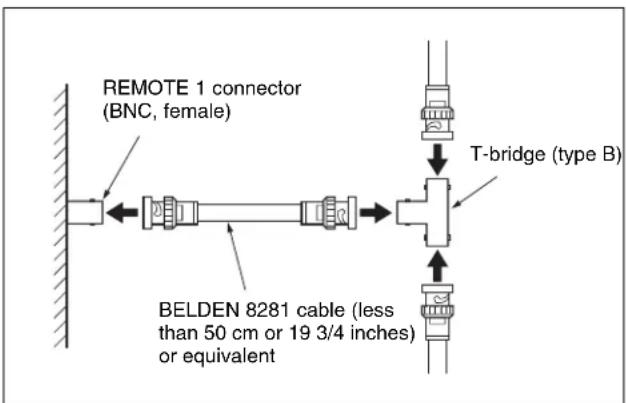
How to use the T-bridge (type B)
A T-bridge of type B is supplied with the IXS-6600/6700. To use it, connect as follows to coaxial cables shorter than 50 cm ( 19^3/_4 inches):
Connection example
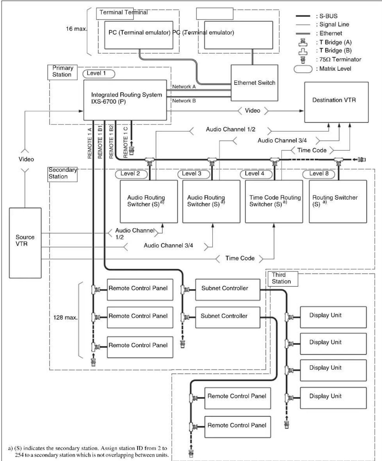
The following diagram shows the configuration of an S-BUS data link with the IXS-6700 as the primary station.
This system cannot control the monitor S-BUS line.
flowchart
graph TD
    A["Source VTR"] --> B["Primary Station"]
    B --> C["Integrated Routing System IXS-6700 (P)"]
    C --> D["Video"]
    C --> E["Secondary Station"]
    E --> F["Remote Control Panel"]
    E --> G["Remote Control Panel"]
    E --> H["Remote Control Panel"]
    C --> I["Audio Channel 1/2"]
    C --> J["Audio Channel 3/4"]
    C --> K["Time Code"]
    C --> L["Time Code 3/4"]
    C --> M["Audio Channel 1/2"]
    C --> N["Audio Channel 3/4"]
    C --> O["Audio Channel 1/2"]
    C --> P["Audio Channel 3/4"]
    C --> Q["Audio Channel 1/2"]
    C --> R["Audio Channel 3/4"]
    C --> S["Audio Channel 1/2"]
    C --> T["Audio Channel 3/4"]
    C --> U["Audio Channel 1/2"]
    C --> V["Audio Channel 3/4"]
    C --> W["Audio Channel 1/2"]
    C --> X["Audio Channel 3/4"]
    C --> Y["Audio Channel 1/2"]
    C --> Z["Audio Channel 3/4"]
    C --> AA["Audio Channel 1/2"]
    C --> AB["Audio Channel 3/4"]
    C --> AC["Audio Channel 1/2"]
    C --> AD["Audio Channel 3/4"]
    C --> AE["Audio Channel 1/2"]
    C --> AF["Audio Channel 3/4"]
    C --> AG["Audio Channel 1/2"]
    C --> AH["Audio Channel 3/4"]
    C --> AI["Audio Channel 1/2"]
    C --> AJ["Audio Channel 3/4"]
    C --> AK["Audio Channel 1/2"]
    C --> AL["Audio Channel 3/4"]
    C --> AM["Audio Channel 1/2"]
    C --> AN["Audio Channel 3/4"]
    C --> AO["Audio Channel 1/2"]
    C --> AP["Audio Channel 3/4"]
    C --> AQ["Audio Channel 1/2"]
    C --> AR["Audio Channel 3/4"]
    C --> AS["Audio Channel 1/2"]
    C --> AT["Audio Channel 3/4"]
    C --> AU["Audio Channel 1/2"]
    C --> AV["Audio Channel 3/4"]
    C --> AW["Audio Channel 1/2"]
    C --> AX["Audio Channel 3/4"]
    C --> AY["Audio Channel 1/2"]
    C --> AZ["Audio Channel 3/4"]
    C --> BA["Audio Channel 1/2"]
    C --> BB["Audio Channel 3/4"]
    C --> BC["Audio Channel 1/2"]
    C --> BD["Audio Channel 3/4"]
    C --> BE["Audio Channel 1/2"]
    C --> BF["Audio Channel 3/4"]
    C --> BG["Audio Channel 1/2"]
    C --> BH["Audio Channel 3/4"]
    C --> BI["Audio Channel 1/2"]
    C --> BJ["Audio Channel 3/4"]
    C --> BK["Audio Channel 1/2"]
    C --> BL["Audio Channel 3/4"]
    C --> BM["Audio Channel 1/2"]
    C --> BN["Audio Channel 3/4"]
    C --> BO["Audio Channel 1/2"]
    C --> BP["Audio Channel 3/4"]
    C --> BQ["Audio Channel 1/2"]
    C --> BR["Audio Channel 3/4"]
    C --> BS["Audio Channel 1/2"]
    C --> BT["Audio Channel 3/4"]
    C --> BU["Audio Channel 1/2"]
    C --> BV["Audio Channel 3/4"]
    C --> BW["Audio Channel 1/2"]
    C --> BX["Audio Channel 3/4"]
    C --> BY["Audio Channel 1/2"]
    C --> BZ["Audio Channel 3/4"]
    C --> CA["Audio Channel 1/2"]
    C --> CB["Audio Channel 3/4"]
    C --> CC["Audio Channel 1/2"]
    C --> CD["Audio Channel 3/4"]
    C --> CE["Audio Channel 1/2"]
    C --> CF["Audio Channel 3/4"]
    C --> CG["Audio Channel 1/2"]
    C --> CH["Audio Channel 3/4"]
    C --> CI["Audio Channel 1/2"]
    C --> CJ["Audio Channel 3/4"]
    C --> CK["Audio Channel 1/2"]
    C --> CR["Audio Channel 3/4"]
    C --> CS["Audio Channel 1/2"]
    C --> CT["Audio Channel 3/4"]
    C --> CU["Audio Channel 1/2"]
    C --> CV["Audio Channel 3/4"]
    C --> CW["Audio Channel 1/2"]
    C --> CX["Audio Channel 3/4"]
    C --> CY["Audio Channel 1/2"]
    C --> CZ["Audio Channel 3/4"]
Locations and Functions of Parts
IXS-6600 Integrated Routing System
Front panel
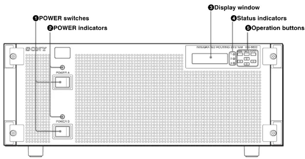
① POWER switches
To turn the power on and off. Power units A and B back up each other. Be sure to set all the two switches to ON.
② POWER indicators
These light when power is supplied to the corresponding power units. The indicators are lit in green when operations are normal.
If a fan in a power unit stops, the corresponding indicator will light in red.
Note
It is not a problem that the POWER indicators may momentarily flash when the power is turned on, nor that one of the POWER switches is set to OFF with both the POWER switches set to ON while the corresponding POWER indicator may still be lit in red.
If you set either the POWER switch to OFF when both the POWER switches are set to ON and soon set it to ON again, the POWER indicator for the power unit whose POWER switch is set to OFF and ON again may remain lit in red. In such a case, set the POWER switch for the power unit whose POWER indicator is lit in red to OFF, wait for about 20 seconds until the indicator goes out, then set that POWER switch to ON again.
If you wish to set the POWER switch or breaker to OFF after setting all the POWER switches to ON, wait for more than 20 seconds before setting it to OFF.
③Display window
Shows the current status of the unit.
For details on errors, see “Status Indications” on page 66.
④Status indicators
These indicate the status of the unit by the color of the indicators and whether they are lit. The indicators are off or lit in green when the power is on and operations are normal. When an error occurs, the indicators light in red.
For details on errors, see “Error Indications and Countermeasures” on page 68.
⑤Operation buttons
Switches the display in the display window.
For details on errors, see "Status Indications" on page 66.
Rear panel
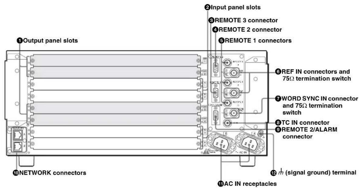
① Output panel slots
For the optional Output Boards.
For details, see "IXS-6600/6700 System Products" on page 49.
②Input panel slots
For the optional Input Boards.
For details, see "IXS-6600/6700 System Products" on page 49.
③REMOTE 3 connector (D-sub 9-pin)
If the switcher is used as the primary station ^1) (set the S1203-3 P/S switch on the CA-65 board to P), connect the terminal emulator to make the settings required for system operations.
Use the D-sub 9-pin connectors with inch screws for connections.
Note
If you are using the REMOTE 3 connector, set the S1203-3 P/S switch on the CA-65 board to the P position.
For further details, refer to the Installation Manual (supplied).
1) Remote control operations via S-BUS protocol consist of a data link constructed using a single coaxial cable link. Several pieces of equipment (i.e. routing switchers, remote control panel (routing switcher control unit), etc.) are connected to this data link for data transmission in time-sharing mode. One of the connected switchers is used as the primary
station that manages the use of the data link, while the other equipment is used as secondary stations which follow directions from the primary station. The response speed may slow down due to the number of secondary stations.
④REMOTE 2 connector (D-sub 9-pin)
Connect an external control unit using a 9-pin remote control cable for use via the RS-422A interface.
When the unit is specified for the primary station (set the S1203-3 P/S switch on the CA-65 board to P), S-BUS Convert mode is selected and S-BUS control via the REMOTE 2 connector is enabled.
Use the D-sub 9-pin connectors with millimeter screws for connections.
For details, refer to the System Setup Manual (supplied).
⑤REMOTE 1 connectors (BNC type)
There are three connectors for three signals, A, B, and C. Connect the remote control panels (routing switcher control units) and routing switchers using a single coaxial cable to control the system via S-BUS protocol. When you use this switcher as the primary station (set the S1203-3 P/S switch on the CA-65 board to P), a maximum of 253 remote control panels and routing switchers can be connected via these three connectors.
When you use this switcher as a secondary station (set the S1203-3 P/S switch on the CA-65 board to S), connect an S-BUS link to one of the connectors using the supplied T-bridge (type B).
For details, see “System Connection Example” on page 56.
Note
Put the supplied 75 terminator(s) on the unused connector(s) regardless whether it is the primary station or secondary station.
⑥ REF IN (reference input) connectors (BNC type) and 75Ω termination switch
There are two connectors for two signals (A and B). The connectors accept analog reference video signals (black burst compatible with CCIR624 standards or tri-level sync for HDTV).
75Ω termination switch
For selecting the input impedance
ON: The input signal is terminated with 75 ohms.
OFF: The input signal is terminated with high impedance. If an external sync signal is used in loop-through configuration, use this position.
Note
If you wish to synchronize signal switching with a reference video signal, set the timing of signal switching (odd or even field) and select reference video signal A or B on the PC (terminal emulator).
For further details, refer to the System Setup Manual (supplied).
⑦ WORD SYNC IN connector (BNC type) and 75Ω termination switch
The connector accepts an audio word sync signal.
75Ω termination switch
For selecting the input impedance
ON: The input signal is terminated with 75 ohms.
OFF: The input signal is terminated with high impedance. If an external sync signal is used in loop-through configuration, use this position.
⑧TC IN (time code input) connector (BNC type)
The connector accepts time code signal.
⑨ REMOTE 2/ALARM connector (D-sub 9-pin)
Supplies the current status of the unit.
This also functions as signal B of the REMOTE 2 connector.
Use the D-sub 9-pin connectors with millimeter screws for connections.
For details, see “Specifications” on page 72 and refer to the Installation Manual and System Setup Manual (supplied).
⑩NETWORK connectors (modular jacks)
There are two connectors for 100BASE-TX communications for signals A and B.
Connect to the Ethernet connector on the PC in which the supplied BZR-20/21 has been installed.
CAUTION
For safety, do not connect the connector for peripheral device wiring that might have excessive voltage to the following ports.
• NETWORK A connector
• NETWORK B connector
Follow the instructions for the above ports.
ATTENTION
When you connect the NETWORK cable of the unit to peripheral device, use a shielded-type cable to prevent malfunction due to radiation noise.
⑪ AC IN (AC power input) receptacles
There are a pair of receptacles (A and B).
Connect each receptacle to an AC outlet using an AC power cord (sold separately). Two power units A and B back up each other. Be sure to make connections to all the two receptacles.
12 ^+ (signal ground) terminal
For signal ground.
IXS-6700 Integrated Routing System
Front panel
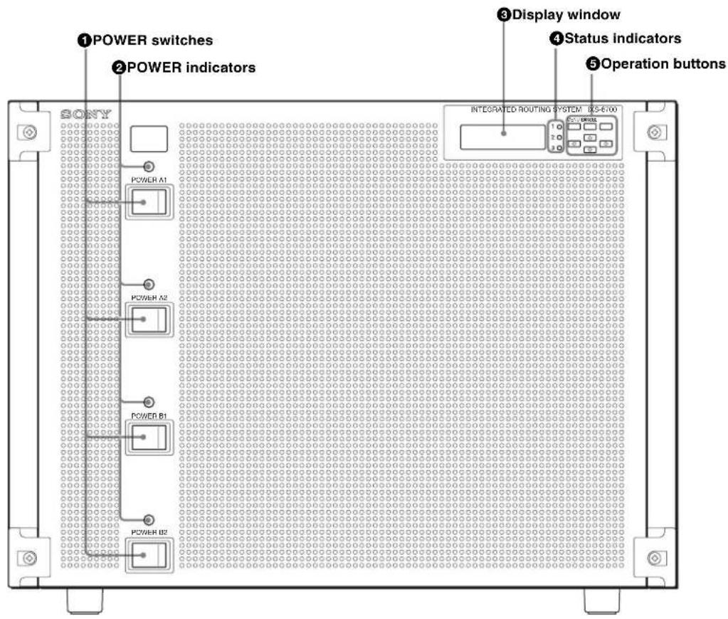
①POWER switches
To turn the power on and off. Power units A1 and B1, and A2 and B2 back up each other. Be sure to set all the four switches to ON.
② POWER indicators
These light when power is supplied to the corresponding power units. The indicators are lit in green when operations are normal.
If a fan in a power unit stops, the corresponding indicator will light in red.
Note
It is not a problem that the POWER indicators may momentarily flash when the power is turned on, nor that some POWER switches are set to OFF when all the
POWER switches are set to ON while the corresponding POWER indicators may still be lit in red.
If you set some POWER switches to OFF when all the POWER switches are set to ON and soon set them to ON again, the POWER indicators for the power units whose POWER switches are set to OFF and ON again may remain lit in red. In such a case, set the POWER switches for the power units whose POWER indicators are lit in red to OFF, wait for about 20 seconds until the indicators go out, then set those POWER switches to ON again.
If you wish to set the POWER switch or breaker to OFF after setting all the POWER switches to ON, wait for more than 20 seconds before setting it to OFF.
③ Display window
Shows the current status of the unit.
For details on errors, see "Status Indications" on page 66.
④Status indicators
These indicate the status of the unit by the color of the indicators and whether they are lit. The indicators are off or lit in green when the power is on and operations are normal. When an error occurs, the indicators light in red.
For details on errors, see "Error Indications and Countermeasures" on page 68.
⑤Operation buttons
Switches the display in the display window.
For details on errors, see "Status Indications" on page 66.
Rear panel
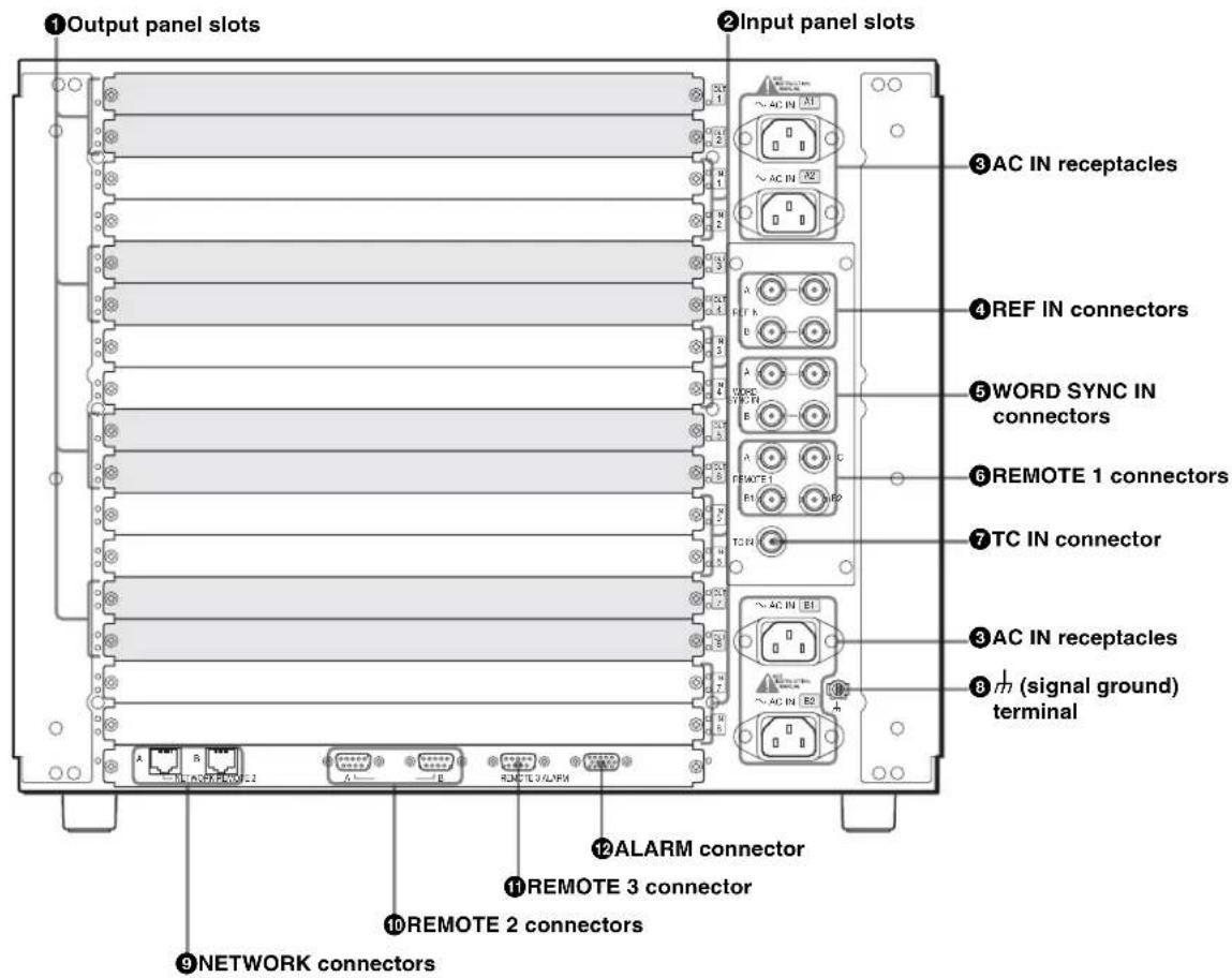
① Output panel slots
For the optional Output Boards.
For details, see "IXS-6600/6700 System Products" on page 49.
② Input panel slots
For the optional Input Boards.
For details, see "IXS-6600/6700 System Products" on page 49.
③ AC IN (AC power input) receptacles
There are two pairs of receptacles (A1/A2 and B1/B2). Connect each receptacle to an AC outlet using an AC power cord (sold separately). Four power units A1 and B1 back up each other, and A2 and B2 back up each other. Be sure to make connections to all the four receptacles.
④REF IN (reference input) connectors (BNC type)
There are four connectors with loop-through function for two signals (A and B).
The connectors accept analog reference video signals (black burst compatible with CCIR624 standards or tri-level sync for HDTV).
Two connectors of each pair have internal loop-through connections. If loop-through output signals are not used, terminate any connector that is not used with a 75Ω terminator.
Note
If you wish to synchronize signal switching with a reference video signal, set the timing of signal switching (odd or even field) and select reference video signal A or B on the PC (terminal emulator).
For further details, refer to the System Setup Manual (supplied).
⑤ WORD SYNC IN connectors (BNC type)
There are four connectors with loop-through function for two signals (A and B).
The connectors accept audio word sync signals.
Two connectors of each pair have internal loop-through connections. If loop-through output signals are not used, terminate any connector that is not used with a 75 terminator.
⑥ REMOTE 1 connectors (BNC type)
There are four connectors for three signals, A, B1/B2, and C (two connectors for B).
Connect the remote control panels (routing switcher control units) and routing switchers using a single coaxial cable to control the system via S-BUS protocol. When you use this switcher as the primary station ^1) (set the S1203-3 P/S switch on the CA-65 board to P), a maximum of 253 remote control panels and routing switchers can be connected via these four connectors.
When you use this switcher as a secondary station ^1) (set the S1203-3 P/S switch on the CA-65 board to S), connect an S-BUS link to one of the connectors using the supplied T-bridge (type B).
For details, see "System Connection Example" on page 56.
Note
Put the supplied 75Ω terminator(s) on the unused connector(s) regardless whether it is the primary station or secondary station.
1) Remote control operations via S-BUS protocol consist of a data link constructed using a single coaxial cable link. Several pieces of equipment (i.e. routing switchers, remote control panel (routing switcher control unit), etc.) are connected to this data link for data transmission in time-sharing mode. One of the connected switchers is used as the primary station that manages the use of the data link, while the other equipment is used as secondary stations which follow directions from the primary station. The response speed may slow down due to the number of secondary stations.
⑦TC IN (time code input) connector (BNC type)
The connector accepts time code signal.
⑧ m (signal ground) terminal
For signal ground.
⑨NETWORK connectors (modular jacks)
There are two connectors for 100BASE-TX communications for signals A and B.
Connect to the Ethernet connector on the PC in which the supplied BZR-20/21 has been installed.
CAUTION
For safety, do not connect the connector for peripheral device wiring that might have excessive voltage to the following ports.
• NETWORK A connector
• NETWORK B connector
Follow the instructions for the above ports.
ATTENTION
When you connect the NETWORK cable of the unit to peripheral device, use a shielded-type cable to prevent malfunction due to radiation noise.
⑩ REMOTE 2 connectors (D-sub 9-pin)
There are two connectors for signals A and B.
Connect an external control unit using a 9-pin remote control cable for use via the RS-422A interface.
When the unit is specified for the primary station (set the S1203-3 P/S switch on the CA-65 board to P), S-BUS Convert mode is selected and S-BUS control via the REMOTE 2 connector is enabled.
Use the D-sub 9-pin connectors with millimeter screws for connections.
For details, refer to the System Setup Manual (supplied).
⑪ REMOTE 3 connector (D-sub 9-pin)
If the switcher is used as the primary station (set the S1203-3 P/S switch on the CA-65 board to P), connect the terminal emulator to make the settings required for system operations.
Use the D-sub 9-pin connectors with inch screws for connections.
Note
If you are using the REMOTE 3 connector, set the S1203-3 P/S switch on the CA-65 board to the P position.
For further details, refer to the Installation Manual (supplied).
12 ALARM connector (Mini D-sub 15-pin)
To output the status of the switchers in the same condition as the status indicators on the front panel.
Use the mini D-sub 15-pin connectors with millimeter screws for connections.
For details, see "Specifications" on page 72 and refer to the Installation Manual and System Setup Manual (supplied).
Option Boards
IKS-V6010M 16 HD/SD Digital Video Input Board
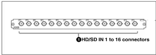
①HD/SD IN 1 to 16 connectors (BNC type)
For SDI signal (143 Mbps to 1485 Mbps) input
IKS-V6010SD 16 SD Digital Video Input Board
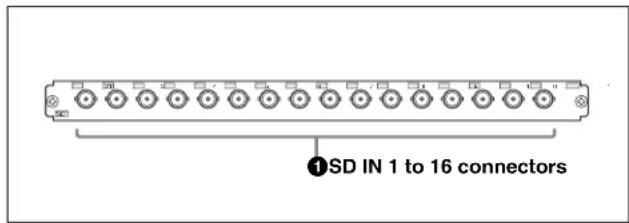
①SD IN 1 to 16 connectors (BNC type)
For SDTV SDI signal (143 Mbps to 360 Mbps) input
IKS-A6011 32 D-sub AES/EBU Input Board
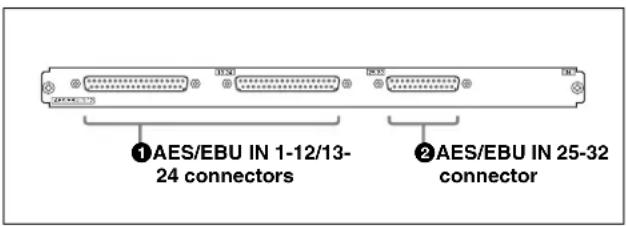
①AES/EBU IN 1-12/13-24 connectors (D-sub 37-pin)
For AES/EBU digital audio signal input
②AES/EBU IN 25-32 connector (D-sub 25-pin)
For AES/EBU digital audio signal input
IKS-A6012 16 BNC AES/EBU Input Board
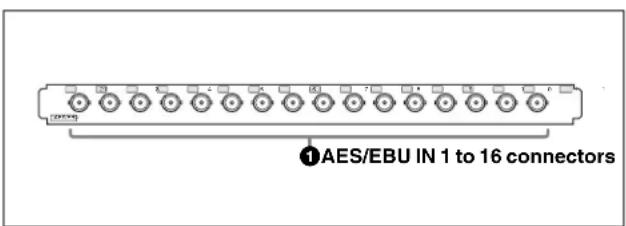
①AES/EBU IN 1 to 16 connectors (BNC type)
For AES/EBU digital audio signal input
IKS-A6013 Analog Audio Input Board
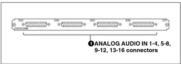
①ANALOG AUDIO IN 1-4, 5-8, 9-12, 13-16 connectors (D-sub 9-pin)
For analog audio signal input
IKS-RS6010 7 RS-422 Input Board
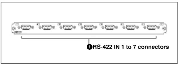
①AES/EBU IN 1 to 16 connectors (BNC type)
For AES/EBU digital audio signal input
IKS-TC6010 16 Time Code Input Board
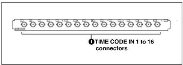
①TIME CODE IN 1 to 16 connectors (BNC type) For time code (LTC) signal input
IKS-V6060M 17 HD/SD Digital Video Output Board
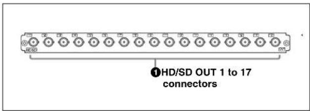
①HD/SD OUT 1 to 17 connectors (BNC type) For SDI signal (143 Mbps to 1485 Mbps) output
IKS-V6060SD 17 SD Digital Video Output Board
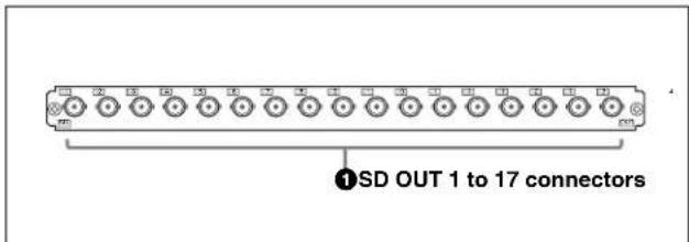
①SD OUT 1 to 17 connectors (BNC type) For SDTV SDI signal (143 Mbps to 360 Mbps) output
IKS-A6061 34 D-sub AES/EBU Output Board
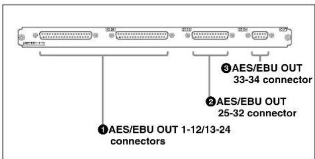
①AES/EBU OUT 1-12/13-24 connectors (D-sub 37-pin) For AES/EBU digital audio signal output
②AES/EBU OUT 25-32 connector (D-sub 25-pin)
For AES/EBU digital audio signal output
③ AES/EBU OUT 33-34 connector (D-sub 9-pin)
For AES/EBU digital audio signal output
IKS-A6062 17 BNC AES/EBU Output Board
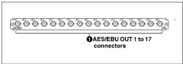
① AES/EBU OUT 1 to 17 connectors (BNC type) For AES/EBU digital audio signal output
IKS-A6063 Analog Audio Output Board
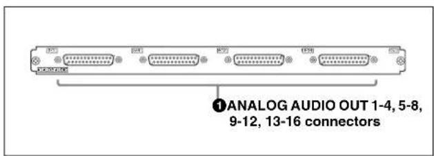
①ANALOG AUDIO OUT 1-4, 5-8, 9-12, 13-16 connectors (D-sub 9-pin) For analog audio signal output
IKS-RS6060 7 RS-422 Output Board
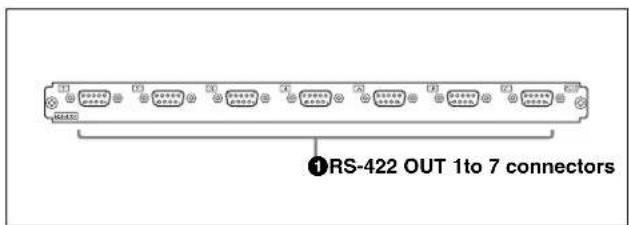
①RS-422 OUT 1to 7 connectors (D-sub 9-pin) For RS-422A signal output
IKS-TC6060 17 Time Code Output Board
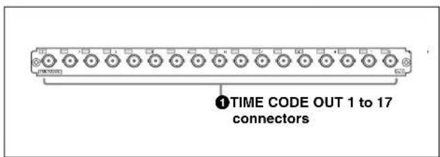
①TIME CODE OUT 1 to 17 connectors (BNC type) For time code (LTC) signal output
Status Indications
The current status of the unit can be displayed in the display window through use of the operation buttons on the front panel.
Displayed Items
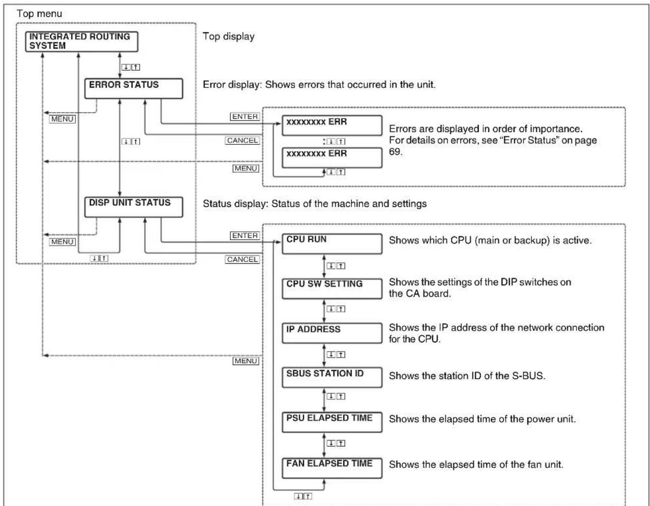
The items displayed in the display window are in a tree configuration, as shown below. You can change the displayed item with the operation buttons.
The backlight of the display window will go off about five minutes after the last operation. Pressing any button makes the backlight go back on.
flowchart
graph TD
A["Top menu"] --> B["INTEGRATED ROUTING SYSTEM"]
B --> C["ERROR STATUS"]
C --> D["INPUT"]
D --> E["INPUT"]
E --> F["DISP UNIT STATUS"]
F --> G["INPUT"]
G --> H["INPUT"]
H --> I["INPUT"]
I --> J["INPUT"]
J --> K["INPUT"]
K --> L["INPUT"]
L --> M["INPUT"]
M --> N["INPUT"]
N --> O["INPUT"]
O --> P["INPUT"]
P --> Q["INPUT"]
Q --> R["INPUT"]
R --> S["INPUT"]
S --> T["INPUT"]
T --> U["INPUT"]
U --> V["INPUT"]
V --> W["INPUT"]
W --> X["INPUT"]
X --> Y["INPUT"]
Y --> Z["INPUT"]
Z --> AA["INPUT"]
AA --> AB["INPUT"]
AB --> AC["INPUT"]
AC --> AD["INPUT"]
AD --> AE["INPUT"]
AE --> AF["INPUT"]
AF --> AG["INPUT"]
AG --> AH["INPUT"]
AH --> AI["INPUT"]
AI --> AJ["INPUT"]
AJ --> AK["INPUT"]
AK --> AL["INPUT"]
AL --> AM["INPUT"]
AM --> AN["INPUT"]
AN --> AO["INPUT"]
AO --> AP["INPUT"]
AP --> AQ["INPUT"]
AQ --> AR["INPUT"]
AR --> AS["INPUT"]
AS --> AT["INPUT"]
AT --> AU["INPUT"]
AU --> AV["INPUT"]
AV --> AW["INPUT"]
AW --> AX["INPUT"]
AX --> AY["INPUT"]
AY --> AZ["INPUT"]
AZ --> BA["INPUT"]
BA --> BB["INPUT"]
BB --> BC["INPUT"]
BC --> BD["INPUT"]
BD --> BE["INPUT"]
BE --> BF["INPUT"]
BF --> BG["INPUT"]
BG --> BH["INPUT"]
BH --> BI["INPUT"]
BI --> BJ["INPUT"]
BJ --> BK["INPUT"]
BK --> BL["INPUT"]
BL --> BM["INPUT"]
BM --> BN["INPUT"]
BN --> BO["INPUT"]
BO --> BP["INPUT"]
BP --> BQ["INPUT"]
BQ --> BR["INPUT"]
BR --> BS["INPUT"]
BS --> BT["INPUT"]
BT --> BU["INPUT"]
BU --> BV["INPUT"]
BV --> BW["INPUT"]
BW --> BX["INPUT"]
BX --> BY["INPUT"]
BY --> BZ["INPUT"]
BZ --> CA["INPUT"]
CA --> CB["INPUT"]
CB --> CC["INPUT"]
CC --> CD["INPUT"]
CD --> CE["INPUT"]
CE --> CF["INPUT"]
CF --> CG["INPUT"]
CG --> CH["INPUT"]
CH --> CI["INPUT"]
CI --> CJ["INPUT"]
CJ --> CK["INPUT"]
CK --> CL["INPUT"]
CL --> CM["INPUT"]
CM --> CN["INPUT"]
CN --> CO["INPUT"]
CO --> CP["INPUT"]
CP --> CQ["OUTPUT"]
subgraph Top display
D1["ERROR STATUS"]
D2["DISP UNIT STATUS"]
D3["CPU RUN"]
D4["CPU SW SETTING"]
D5["IP ADDRESS"]
D6["SBUS STATION ID"]
D7["PSU ELAPSED TIME"]
D8["FAN ELAPSED TIME"]
D9["ENO}}}:::l<br> D10["CANCEL"]
D11["ENTER"]
D12["xxxxxxx ERR"]
D13["xxxxxxx ERR"]
D14["xxxxxxx ERR"]
D15["xxxxxxx ERR"]
D16["xxxxxxx ERR"]
D17["xxxxxxx ERR"]
D18["xxxxxxx ERR"]
D19["xxxxxxx ERR"]
D20["xxxxxxx ERR"]
D21["xxxxxxx ERR"]
D22["xxxxxxx ERR"]
D23["xxxxxxx ERR"]
D24["xxxxxxx ERR"]
D25["xxxxxxx ERR"]
D26["xxxxxxx ERR"]
D27["xxxxxxx ERR"]
D28["xxxxxxx ERR"]
D29["xxxxxxx ERR"]
D30["xxxxxxx ERR"]
D31["xxxxxxx ERR"]
D32["xxxxxxx ERR"]
D33["xxxxxxx ERR"]
D34["xxxxxxx ERR"]
D35["xxxxxxx ERR"]
D36["xxxxxxx ERR"]
D37["xxxxxxx ERR"]
D38["xxxxxxx ERR"]
D39["xxxxxxx ERR"]
D40["xxxxxxx ERR"]
D41["xxxxxxx ERR"]
D42["xxxxxxx ERR"]
D43["xxxxxxx ERR"]
D44["xxxxxxx ERR"]
D45["xxxxxxx ERR"]
D46["xxxxxxx ERR"]
D47["xxxxxxx ERR"]
D48["xxxxxxx ERR"]
D49["xxxxxxx ERR"]
D50["xxxxxxx ERR"]
D51["xxxxxxx ERR"]
D52["xxxxxxx ERR"]
D53["xxxxxxx ERR"]
D54["xxxxxxx ERR"]
D55["xxxxxxx ERR"]
D56["xxxxxxx ERR"]
D57["xxxxxxx ERR"]
D58["xxxxxxx ERR"]
D59["xxxxxxx ERR"]
D60["xxxxxxx ERR"]
D61["xxxxxxx ERR"]
D62["xxxxxxx ERR"]
D63["xxxxxxx ERR"]
D64["xxxxxxx ERR"]
D65["xxxxxxx ERR"]
D66["xxxxxxx ERR"]
D67["xxxxxxx ERR"]
D68["xxxxxxx ERR"]
D69["xxxxxxx ERR"]
D70["xxxxxxx ERR"]
D71["xxxxxxx ERR"]
D72["xxxxxxx ERR"]
D73["xxxxxxx ERR"]
D74["xxxxxxx ERR"]
D75["xxxxxxx ERR"]
D76["xxxxxxx ERR"]
D77["xxxxxxx ERR"]
D78["xxxxxxx ERR"]
D79["xxxxxxx ERR"]
D80["xxxxxxx ERR"]
D81["xxxxxxx ERR"]
D82["xxxxxxx ERR"]
D83["xxxxxxx ERR"]
D84["xxxxxxx ERR"]
D85["xxxxxxx ERR"]
D86["xxxxxxx ERR"]
D87["xxxxxxx ERR"]
D88["xxxxxxx ERR"]
D89["xxxxxxx ERR"]
D90["xxxxxxx ERR"]
D91["xxxxxxx ERR"]
D92["xxxxxxx ERR"]
D93["xxxxxxx ERR"]
D94["xxxxxxx ERR"]
D95["xxxxxxx ERR"]
D96["xxxxxxx ERR"]
D97["xxxxxxx ERR"]
D98["xxxxxxx ERR"]
D99["xxxxxxx ERR"]
E1["CPU RUN"]
E2["CPU SW SETTING"]
E3["IP ADDRESS"]
E4["SBUS STATION ID"]
E5["PSU ELAPSED TIME"]
E6["FAN ELAPSED TIME"]
end
note right of E1 "ERROR Status" is important. For details on errors, see "Error Status" on page 69.
Status display: Status of the machine and settings
Shows which CPU (main or backup) is active.
Shows the settings of the DIP switches on the CA board.
Shows the IP address of the network connection for the CPU.
Shows the station ID of the S-BUS.
Shows the elapsed time of the power unit.
Shows the elapsed time of the fan unit.
Menu labels: INPUT, OUTPUT, MODE, MENU, INPUT, OUTPUT, MENU, INPUT, INPUT, MENU, INPUT, MENU, INPUT, MENU, INPUT, MENU, INPUT, MENU, INPUT, MENU, INPUT, MENU, INPUT, MENU, INPUT, MENU, INPUT, MENU, INPUT, MENU, INPUT, MENU, INPUT, MENU, INPUT, MENU, INPUT, MENU, INPUT, MENU, INPUT, MENU, INPUT, MENU, INPUT, MENU, INPUT, MENU, INPUT, MENU, INPUT, MENU, INPUT, MENU, INPUT, MENU, INPUT, MENU, INPUT, Controller, System Name, System Name Type, System Name Status, System Name Status Description
Functions of the Operation Buttons
flowchart
graph TD
    A["①MENU button"] --> B["②CANCEL button"]
    B --> C["③ENTER button"]
    D["MENU ENTER"] --> E["④buttons"]
    F["⑤buttons"] --> G["④buttons"]
    E --> H["④buttons"]
    G --> I["④buttons"]
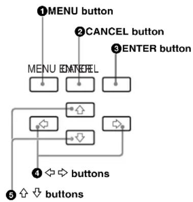
①MENU button
Press to return to the top display.
②CANCEL button
On a layer below the top menu, this button lets you move to the next layer above.
Press to retrieve the stored settings, canceling any changes not yet stored.
③ENTER button
This button lets you move to the next layer below.
Press to store your settings when the settings have been changed.
When this button is pressed together with the MENU button, the setting menu is displayed.
4 ⇔ ➔ buttons
Press to select an option or move to the adjacent digit of the value.
⑤ ↗ ↓ buttons
Press to change the displayed item on the same layer.
Basic Operations
Basic operations using the operation buttons are as follows:
To display the top display in the display window
Press the MENU button. The top display (INTEGRATED ROUTING SYSTEM) appears in the display window. If the backlight is not lit, press the MENU button again, and the backlight will light.
To move to the next layer below
Press the ENTER button.
To move to the next layer above
Press the CANCEL button.
To change the displayed item on the same layer
Press the ⊕ or ↓ button.
To return to the top display
Press the MENU button.
Confirming the Status of the Machine
You can confirm the settings of the DIP switches on the internal board, Station ID of the S-BUS station, etc. Proceed as follows:
1 Press the MENU button to display the top display.
2 Press the ↑ or ↓ button to display DISP UNIT STATUS in the display window.
3 Press the ENTER button.
4 Press the or button to select an item whose settings are to be confirmed.
CPU RUN: Which CPU (main or backup) is active
CPU SW SETTING: Settings of the DIP switches on the CA-65 board
IP ADDRESS: IP address of the network connection of the CPU
SBUS STATION ID: Station ID of the S-BUS station
PSU ELAPSED TIME: Elapsed time of each power unit
FAN ELAPSED TIME: Elapsed time of each fan unit
5 Press the ENTER button.
The item selected in step 4 appears on the second line of the display window.
Press the or button to change the displayed item.
Adjusting the Contrast of the Display Window
You can adjust the contrast of the display window.
Proceed as follows:
1 Press the MENU button to display the top display.
2 Press the ⇔ or ⇒ button to adjust the contrast.
Pressing the button increases the contrast, and pressing the button decreases it.
Error Indications and Countermeasures
This switcher performs self-diagnostics when you turn the power on or press the reset button on the CPU board (CA-65) that functions as the main board, as well as at regular intervals during operation. If the self-diagnostics detect an error, the status indicator lights, and information about the error is output to the control terminal (terminal emulator on a PC).
The error code and ERROR No. shown in the status display on the CA-65 board also indicate errors.
You can easily determine the origin of an error through such indications.
The errors indicated with the status indicators and in the display window, as well as their respective countermeasures, are shown in the tables below.
Status Indicators
Status indicators may be unstable for several seconds when the power is turned on, but this is not a problem.
| Status indicators | Meaning | Status | Countermeasures | ||
| Lit in green Lit in amber Lit in red | |||||
| 1 Redundant status (status of the power units and CA-65 boards) | Normal (The power units and CA-65 boards operate normally.) | One of the two CA-65 boards is not inserted in a slot.The power unit is removed.The elapsed time of the power unit exceeds the defined period for periodic replacement. | Abnormal operation is detected on the CA-65 board.Some trouble may occur in the power unit. | Check the meaning of the error and take countermeasures.Confirm that the switch on the power unit is set to ON.Confirm connection of the power cables.Replace a defective power unit.Replace a defective CA-65 board. | |
| 2 Unit status | (status of the fan units, internal temperature, optional boards) | Normal (The fan units, internal temperature, and optional boards are all normal.) | The elapsed time of the fan unit exceeds the defined period for periodic replacement. | Some trouble may occur with the fan unit, internal temperature, or optional boards. | Check the meaning of the error and take the countermeasures.Replace a defective fan unit or optional board.Replace a defective optional board. |
| 3 Remote control/ timing status (status of the REMOTE 1 or NETWORK connectors or reference signal input) | Normal (Communication via the REMOTE 1 and NETWORK connectors is normal, and the normal reference signal is input. Or a reference signal is not input, but the setting enables crosspoint switching asynchronously.) | Some trouble | may occur in the REMOTE 1 or NETWORK communication or reference video signal input. | Check the meaning of the error and take the countermeasures.Make settings and connections of the REMOTE 1 and NETWORK connectors.Supply the reference video signal or set the timing of switching crosspoints to ASYNC.For details, refer to the System Setup Manual (supplied). | |
Error Status
You can display the error status in the display window. Proceed as follows:
1 Press the MENU button to display the top display in the display window.
2 Press the ↓ button.
ERROR STATUS appears.
3 Press the ENTER button.
The error status is displayed in order of importance.
The item for which the status is displayed can be changed by pressing the or button.
To move to the next layer above
Press the CANCEL button.
To return to the top display
Press the MENU button.
Error status and countermeasures
| Display on the 1st line | Display on the 2nd line | Word in “x” Meaning Countermeasures | |
| REMOTE1 ERR | DISCONNECT CH.xx | A/B1/B2/C S-BUS line is disconnected. • Check the connection with a device not responding, and connect it correctly.• Use a 75 Ω terminator. | |
| REF ERR FAIL | CH.x A/B Abnormal | • Supply a reference video signal to the REF IN connector.• Cancel crosspoint switching synchronized with a reference video signal (set to ASYNC). For details, refer to the System Setup Manual (supplied). | |
| W/S ERR FAIL | CH.x A/B | a) | Abnormal• An optional audio board is attached, but an audio reference (word sync) signal or reference video signal is not input.• A reference signal not supported is input to the WORD SYNC IN connector. |
| MAIN CPU ERR | MEM ERR — | • Backup data for the main CA-65 board are destroyed. | • Check the main CA-65 board (see “Displayed Items” on page 66), and download the backup data referring the Installation Manual. |
| BATT.VOLTAGE LOW | — | • Voltage of the backup battery for the main CA-65 board is abnormal. | |
| BACKUP CPU ERR | DOWN | — | • There is a problem with the backup CA-65 board. |
| PSU ERR | FAIL xx | A1/A2/B1/B2b) | • There is a problem with the power unit. |
| NON xx | A1/A2/B1/B2b) | • No power unit is installed. | |
| xx RUN HOUR OVER | A1/A2/B1/B2b) | • The elapsed time of the power unit is past the defined time for periodic replacement. | |
| Display on the 1st line | Display on the 2nd line | Word in “x” | Meaning | Countermeasures |
| FAN ERR x UNIT | FAIL L/R • One or more fan units stop or rotation speed exceeds the defined value. | • Replace any defective fan units. | ||
| x RUN HOURS OVER | L/R • The elapsed time of the fan unit is past the defined time for periodic replacement. | • Replace the fan unit indicated by OVER. | ||
| TEMP ERR HIGH | — • Internal temperature exceeds the defined value. | • Check the ambient temperature and the ventilation condition of the unit. | ||
| XPT ERR INxxx- | OUTxxx Input and output connector number | • There is a problem with the crosspoint. | • Replace a defective optional board. | |
| OPTION BD.ERR | FRONT SLOTxx | 1/2/3/4/5/6/7^c) | • There is a problem with the optional front board inserted in the unit. | • Replace a defective optional board. |
| • The slot where the board is inserted is not correct. | • Insert the board in the correct slot. | |||
| REAR SLOTxx 1 | /2/3/4/5/6/7/8/9/10/11/12/13/14/15/16^d) | • There is a problem with the optional rear board inserted in the unit. | • Replace a defective optional board. | |
| • The slot where the board is inserted is not correct. | • Insert the board in the correct slot. | |||
| S-BUS CPU ERR | MAINx FAIL A/B/C | • There is a problem with the S-BUS CPUx on the main CPU board. | • Replace the defective IF-844 board on the main CA-65 board. | |
| BACKUPx FAIL | A/B/C | • There is a problem with the S-BUS CPUx on the backup CPU board. | • Replace the defective IF-844 board on the backup CA-65 board. | |
a) The IXS-6600 has only one WORD SYNC IN connector, but the input signal is divided into two lines of A and B in the unit.
b) A2 and B2 are not displayed on the IXS-6600. Power unit A and B of the IXS-6600 are displayed as A1 and B1 in the display window, respectively.
c) On the IXS-6600, 5, 6, and 7 are not displayed.
d) The displayed slot number corresponds to the input or output slot number on the rear panel of the IXS-6600/6700 as shown below.
| Slot number | IXS-6700 | IXS-6600 |
| 1 | OUT1 | OUT1 |
| 2 | OUT2 | OUT2 |
| 3 | IN1 | IN1 |
| 4 | IN2 | IN2 |
| 5 | OUT3 | OUT3 |
| 6 | OUT4 | OUT4 |
| 7 | IN3 | IN3 |
| 8 | IN4 | IN4 |
| 9 | OUT5 | -- |
| 10 | OUT6 | -- |
| 11 | IN5 | -- |
| 12 | IN6 | -- |
| 13 | OUT7 | -- |
| 14 | OUT8 | -- |
| 15 | IN7 | -- |
| 16 | IN8 | -- |
Supplied Software
The CD-ROM supplied with the IXS-6600/6700 includes the software described below.
BZR-20 Routing Switcher Data Backup Software
This backs up the setting data for the IXS-6600/6700 for servicing.
This can be installed on an IBM PC/AT-compatible machine with Windows XP.
For details, refer to the Installation Manual (supplied).
BZR-21 Routing Switcher Remote Control Software
This enables basic functions such as switching crosspoints, assigning connectors to the switching operation buttons, and checking the operations for configuring the large or small system for easy operations.
This can be installed on an IBM PC/AT-compatible machine with Windows XP.
Installing BZR-21
This enables crosspoint switching from a PC. The software also has a function to display the crosspoint statuses and one to find destinations for which a source has been selected.
Operational environment
Hardware: IBM PC/AT-compatible machine with Windows XP
CPU: Pentium or equivalent processor with clock speed of 300 MHz or more
Main memory: 128 MB or more
Hard disk space: 10 MB or more
Display device: Resolution of 800 × 600 pixels or more
Interface: RS-232C or Ethernet
Overview of crosspoint switching with BZR-21
You may select the Button per Source system (a method for switching crosspoints by pressing buttons to which appropriate terminals have been assigned in advance) or the X-Y system (for switching crosspoints by specifying terminal names). With the Distribution system, you can specify multiple destinations for a single source.
Select your desired system by clicking on the appropriate tab in the main window.
Button per Source system
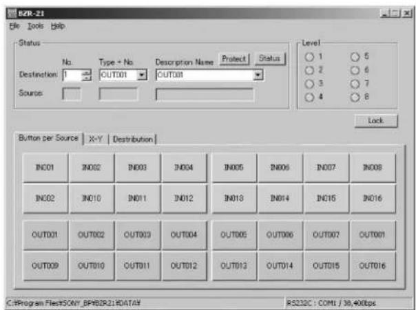
X-Y system
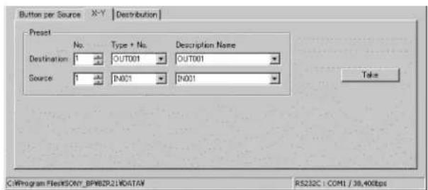
Distribution system
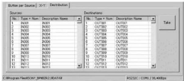
Terminal assignment to buttons
For switching with the Button per Source system, you can assign terminals to the operation buttons displayed in the window by drag & drop operation.
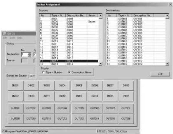
Installation procedure
1 Load a CD-ROM supplied with the IXS-6600/6700 into the CD-ROM drive.
2 Copy all the files in the \BZR-21 folder from the CD-ROM to a folder on the hard disk.
Note
Use only alphanumerics for the name of a new folder.
3 When copying is completed, double-click on the SETUP.EXE icon.
The installation program will start. Follow the instructions displayed on the screen.
For details on operations with BZR-21, refer to online help of BZR-21.
Note
In “Overview of BZR-21” of BZR-21 online help, it is written “Use the REMOTE 3 (RS-232C) or DATA (Ethernet) connector for connecting with the primary station.” However, on the IXS-6600/6700, use the NETWORK connector (Ethernet) instead of the DATA (Ethernet) connector.
Specifications
The specifications below are for the IXS-6600/6700 and optional boards.
Design and specifications are subject to change without notice.
Note
Always verify that the unit is operating properly before use. SONY WILL NOT BE LIABLE FOR DAMAGES OF ANY KIND INCLUDING, BUT NOT LIMITED TO, COMPENSATION OR REIMBURSEMENT ON ACCOUNT OF THE LOSS OF PRESENT OR PROSPECTIVE PROFITS DUE TO FAILURE OF THIS UNIT, EITHER DURING THE WARRANTY PERIOD OR AFTER EXPIRATION OF THE WARRANTY, OR FOR ANY OTHER REASON WHATSOEVER.
IXS-6700 Integrated Routing System
General
Power requirements 100 to 240 V AC, 50 to 60 Hz Current drain (maximum value with the full configuration with optional boards)
9.8 A at 100 V AC
4.5 A at 240 V AC
Peak inrush current (1) Power ON, current probe method: 145 A (100 V), 110 A (240 V)
(2) Hot switching inrush current, measured in accordance with European standard EN55103-1: 100 A (230 V)
Operating temperature
5^ to 40^ (41°F to 104°F)
Operating humidity 10% to 90% (no condensation)
Performance-guaranteed temperature
10^ to 35^ (50°F to 95°F)
Mass (excluding optional boards)
Approx. 28 kg (61 lb 12 oz)
Dimensions (w/h/d) 440 × 354 × 520 mm
(17^3/8× 14× 20^1/2 inches)
Mountable units
Supplied units Power unit (4)
CPU control board (2)
Optional units IKS-6030M Matrix Board
IKS-V6050M HD/SD Video Router
Processor Board
IKS-V6050SD SD Video Router Processor Board
IKS-A6050 Audio/Data Router Processor Board
IKS-V6010M 16 HD/SD Digital Video Input Board
IKS-V6010SD 16 SD Digital Video Input Board
IKS-A6011 32 D-sub AES/EBU Input Board
IKS-A6012 16 BNC AES/EBU Input Board
IKS-A6013 Analog Audio Input Board
IKS-A6015 32 Sampling Rate Converter Board
IKS-RS6010 7 RS-422 Input Board
IKS-TC6010 16 Time Code Input Board
IKS-V6060M 17 HD/SD Digital Video Output Board
IKS-V6060SD 17 SD Digital Video Output Board
IKS-A6061 34 D-sub AES/EBU Output Board
IKS-A6062 17 BNC AES/EBU Output Board
IKS-A6063 Analog Audio Output Board
IKS-RS6060 7 RS-422 Output Board
IKS-TC6060 17 Time Code Output Board
Input/output connectors
REMOTE 1 S-BUS remote connector: BNC type (4)
Data transfer rate: 312/1,250 Kbps
Data transfer format: Bi-Phase Space
Signal transfer distance: 500 m at 312 Kbps (when using a BELDEN 8281 75Ω coaxial cable or equivalent)
REMOTE 2 D-sub 9-pin, female (2)
Complies with RS-422A signal standard (can be converted to S-BUS commands)
Protocol: Sony Cart++
Data transfer rate: 38.4 Kbps
REMOTE 3 D-sub 9-pin, male (1)
Complies with RS-232C signal standard.
For terminal connection
Data transfer rate: 38,400 bps
8 bits, no parity, no check, 1 stop bit
TC IN BNC type (1)
ALARM Mini D-sub 15-pin, female (1)
Parallel, open-collector 6 outputs
REF IN BNC type (2) (with loop-through outputs)
Black burst
HD tri-level sync
When used as a reference signal for a digital audio signal:
1125i/50, 59.94, 60
750p/59.94, 60
625i/50
525i/59.94, 60
525p/59.94
WORD SYNC IN BNC type (2) (with loop-through outputs)
NETWORK 100BASE-TX: modular jack (2)
Accessories supplied
Operation Guide (1)
CD-ROM (1)
Contents Operation Manual
Installation Manual
System Setup Manual
BZR-20 Routing Switcher Data Backup Software
BZR-21 Routing Switcher Remote Control Software
BZR-25 Network Setting GUI Software
75Ω terminators (3)
T-bridge (type B) (1)
Optional accessories
AC power cord
for USA and Canada only (125 V, 10 A, 2.4 m (8 ft))
Part No.: 1-557-377-11
for Europe only (250 V, 10 A, 2.4 m (8 ft))
Part No.: 1-782-929-22
IXS-6600 Integrated Routing System
General
Power requirements 100 to 240 V AC, 50 to 60 Hz
Current drain (maximum value with the full configuration with optional boards)
6 A at 100 V AC
2.5 A at 240 V AC
Peak inrush current (1) Power ON, current probe method: 100 A (100 V), 100 A (240 V)
(2) Hot switching inrush current, measured in accordance with European standard EN55103-1: 75 A (230 V)
Operating temperature
5^ to 40^ (41°F to 104°F)
Operating humidity 10% to 90% (no condensation)
Performance-guaranteed temperature
10^ to 35^ ( 50^ to 95^)
Mass (excluding optional boards)
Approx. 17 kg (37 lb 7 oz)
Dimensions (w/h/d) 440 × 176 × 520 mm
(17^3/8× 7× 20^1/2 inches)
Mountable units
Supplied units Power unit (2)
CPU control board (2)
Optional units IKS-6030M Matrix Board
IKS-V6050M HD/SD Video Router Processor Board
IKS-V6050SD SD Video Router Processor Board
IKS-A6050 Audio/Data Router Processor Board
IKS-V6010M 16 HD/SD Digital Video Input Board
IKS-V6010SD 16 SD Digital Video Input Board
IKS-A6011 32 D-sub AES/EBU Input Board
IKS-A6012 16 BNC AES/EBU Input Board
IKS-A6013 Analog Audio Input Board
IKS-A6015 32 Sampling Rate Converter Board
IKS-RS6010 7 RS-422 Input Board
IKS-TC6010 16 Time Code Input Board
IKS-V6060M 17 HD/SD Digital Video Output Board
IKS-V6060SD 17 SD Digital Video Output Board
IKS-A6061 34 D-sub AES/EBU Output Board
IKS-A6062 17 BNC AES/EBU Output Board
IKS-A6063 Analog Audio Output Board
IKS-RS6060 7 RS-422 Output Board
IKS-TC6060 17 Time Code Output Board
Input/output connectors
REMOTE 1 S-BUS remote connector: BNC type (3)
Data transfer rate: 312/1,250 Kbps
Data transfer format: Bi-Phase Space
Signal transfer distance: 500 m at
312 Kbps (when using a BELDEN
8281 75Ω coaxial cable or equivalent)
REMOTE 2/ALARM
D-sub 9-pin, female (2)
REMOTE 2: Complies with RS-
422A signal standard (can be converted to S-BUS commands)
Protocol: Sony Cart++
Data transfer rate: 38.4 Kbps
ALARM: Parallel, Open collector 4 outputs
REMOTE 3 D-sub 9-pin, male (1)
Complies with RS-232C signal standard.
For terminal connection
Data transfer rate: 38,400 bps
8 bits, no parity, no check, 1 stop bit
TC IN BNC type (1)
REF IN BNC type (2)
Black burst
HD tri-level sync
When used as a reference signal for a digital audio signal:
1125i/50, 59.94, 60
750p/59.94, 60
625i/50
525i/59.94, 60
525p/59.94
WORD SYNC IN BNC type (1)
NETWORK 100BASE-TX: modular jack (2)
Accessories supplied
Operation Guide (1)
CD-ROM (1)
Contents Operation Manual
Installation Manual
System Setup Manual
BZR-20 Routing Switcher Data Backup Software
BZR-21 Routing Switcher Remote Control Software
BZR-25 Network Setting GUI Software
75Ω terminators (2)
T-bridge (type B) (1)
Optional accessories
AC power cord
for USA and Canada only (125 V, 10 A, 2.4 m (8 ft))
Part No.: 1-557-377-11
for Europe only (250 V, 10 A, 2.4 m (8 ft))
Part No.: 1-782-929-22
Optional Boards
IKS-6030M Matrix Board
General
Power requirements 12 V DC
Current drain 4.2 A
Dimensions (h/d) 317 × 380 ~mm (12^1 / _2 × 15 inches)
Mass Approx. 1.3 kg (2 lb 14 oz)
Characteristics
Matrix size 128 inputs × 68 outputs (256 inputs × 136 outputs for audio signals)
Data transfer rate DC to 1,485 Mbps
Accessory supplied
Operation and Installation Guide (1)
IKS-V6050M HD/SD Video Router Processor Board
General
Power requirements 12 V DC
Current drain 2.2 A
Dimensions (h/d) 317 × 380 mm
$$ \left(1 2 ^ {1} / _ {2} \times 1 5 \text { inches }\right) $$
Mass Approx. 1.0 kg (2 lb 7 oz)
Characteristics
Signal processing 34 signals
Data transfer rate 143 to 1,485 Mbps
Reclocked operation signal
SMPTE standard 143, 177, 270, 360,
540, 1,483.5/1,485 Mbps
DVB/ASI standard 270 Mbps signals
Accessory supplied
Operation and Installation Guide (1)
IKS-V6050SD SD Video Router Processor Board
General
Power requirements 12 V DC
Current drain 2.2 A
Dimensions (h/d) 317 × 380 mm (12^1/_2 × 15 inches)
Mass Approx. 1.0 kg (2 lb 7 oz)
Characteristics
Signal processing 34 signals
Data transfer rate 143 to 360 Mbps
Reclocked operation signal
SMPTE standard 143, 177, 270, 360
Mbps
DVB/ASI standard 270 Mbps
signals
Accessory supplied
Operation and Installation Guide (1)
IKS-A6050 Audio/Data Router Processor Board
General
Power requirements 12 V DC
Current drain 1.0 A
Dimensions (h/d) 317 × 380 mm
$$ (1 2 ^ {1} / _ {2} \times 1 5 \text { inches }) $$
Mass Approx. 1.1 kg (2 lb 7 oz)
Characteristics
Signal processing 28 signals (for data signal (RS-422A))
68 signals (for AES/EBU digital audio signals (balanced))
Processed signal Digital audio signal, RS-422A signal
Accessory supplied
Operation and Installation Guide (1)
IKS-V6010M 16 HD/SD Digital Video Input Board
General
Power requirements 12 V DC
Current drain 1.0 A
Dimensions (h/d) 278 × 95.6 mm
$$ (1 1 \times 3 ^ {7} / _ {8} \text { inches }) $$
Mass Approx. 0.4 kg (14 oz)
Characteristics
Number of inputs 16 (BNC type)
Input signal SDI signal, 0.8 Vp-p
Input data transfer rate
143 to 1,485 Mbps
Signal transfer distance
143 to 360 Mbps: 200 m (when using a BELDEN 8281 cable or equivalent)
540 Mbps: 150 m (when using a BELDEN 8281 cable or equivalent)
1,485 Mbps: 100 m (when using a BELDEN 1694 cable or equivalent)
Note
If a BNC cable is connected to an input connector with its end open, the signal detection circuit of this unit may malfunction owing to ambient noise. In such a case, terminate the end of the cable with 75 .
Accessory supplied
Operation and Installation Guide (1)
IKS-V6010SD 16 SD Digital Video Input Board
General
Power requirements 12 V DC
Current drain 1.0 A
Dimensions (h/d) 278 × 95.6 mm
$$ (1 1 \times 3 ^ {7} / _ {8} \text { inches }) $$
Mass Approx. 0.4 kg (14 oz)
Characteristics
Number of inputs 16 (BNC type)
Input signal SDTV SDI signal, 0.8 Vp-p
Input data transfer rate
$$ 1 4 3 \text { to } 3 6 0 \text { Mbps } $$
Signal transfer distance
200 m (when using a BELDEN 8281
If a BNC cable is connected to an input connector with its end open, the signal detection circuit of this unit may malfunction owing to ambient noise. In such a case, terminate the end of the cable with 75 .
Accessory supplied
Operation and Installation Guide (1)
IKS-A6011 32 D-sub AES/EBU Input Board
General
Power requirements 12 V DC
Current drain 0.34 A
Dimensions (h/d) 278 × 95.6 mm
$$ (1 1 \times 3 ^ {7} / _ {8} \text { inches }) $$
Mass Approx. 0.3 kg (11 oz)
Characteristics
Number of inputs 32 (D-sub 37-pin (2), D-sub 25-pin (1))
Input signal 24 bit digital audio signal
conforming to AES3-2003 and
AES-2id-1996(r2001)6.3,
synchronizing with the reference
video signal or word sync signal
Standard input signal level
2 to 7 Vp-p (differential, 110Ω terminated)
Maximum input signal level
10 Vp-p (differential, 110 terminated)
Minimum input signal level
0.5 V (Fs = 48 kHz)
(differential,110Ω terminated)
Input data transfer rate (sampling rate)
6.144 Mbps (Fs=48 kHz)
Signal transfer distance
6.144 Mbps: 300 m or more
(signal source level:5 Vp-p
differential, when using a cable for digital audio signals)
Note
For an input signal which is not synchronized with the reference video signal or word sync signal or whose transfer rate does not match with the above value, it is recommended to use an IKS-A6015 32 Sampling Rate Converter Board together with this board.
Accessory supplied
Operation and Installation Guide (1)
IKS-A6012 16 BNC AES/EBU Input Board
General
Power requirements 12 V DC
Current drain 0.60 A
Dimensions (h/d) 278 × 95.6 mm
$$ (1 1 \times 3 ^ {7} / _ {8} \text { inches }) $$
Mass Approx. 0.3 kg (11 oz)
Characteristics
Number of inputs 16 (BNC type)
Input signal 24 bit digital audio signal
conforming to AES3-2003 and
AES-3id-1995 7, synchronizing
with the reference video signal or word sync signal
Standard input signal level
0.8 to 1.2 Vp-p (75Ω terminated)
Maximum input signal level
7 Vp-p (75Ω terminated)
Minimum input signal level
Conforming to AES-3id-2001 7.3
Minimum input signals
Vmin=320 mV (75Ω terminated)
Input data transfer rate (sampling rate)
6.144 Mbps (Fs=48 kHz)
Signal transfer distance
6.144 Mbps: 600 m or more
(signal source level:1 Vp-p, when using a BELDEN 8281 cable or equivalent)
Note
For an input signal which is not synchronized with the reference video signal or word sync signal or whose transfer rate does not match with the above value, it is recommended to use an IKS-A6015 32 Sampling Rate Converter Board together with this board.
Accessory supplied
Operation and Installation Guide (1)
IKS-A6013 Analog Audio Input Board
General
Power requirements 12 V DC
Current drain 0.9 A
Dimensions (h/d) 278 × 95.6 mm
(11× 3^7 / _8 inches)
Mass Approx. 0.4 kg (14 oz)
Inputs
Analog audio input D-sub 25-pin (female) (4)
2-channel stereo
Balanced (electric balance)
Input channels 8 stereo
Input impedance 600Ω (typical) /20 kΩ (selectable with the internal switch)
Reference input level +4 dBm (-10 dBm to +8 dBm continuously adjustable)
A/D conversion characteristics
Quantization 24-bit linear/48 kHz sampling
Headroom 20 dB (at reference level)
Frequency response 20 Hz to 20 kHz
±0.1 dB (AES/EBU output)
+0.2/-0.3 dB (analog audio output)
Distortion less than 0.05% (1 kHz, reference
level, 24 kHz low pass)
S/N ratio more than 90 dB (AES/EBU output)
more than 85 dB (analog audio signal)
(maximum output level, 24 kHz low pass)
Crosstalk less than -85dB (at 15 kHz or less)
Pre-emphasis not applied
Reference input
Audio clock synchronizing with the audio word sync of the IXS-6600/6700
Accessory supplied
Operation and Installation Guide (1)
IKS-A6015 32 Sampling Rate Converter Board
General
Power requirements 3.3 V DC (supplied from the IKS-A6011)
Current drain 0.96 A
Dimensions (h/d) 116 × 62 mm
(4^5/8× 2^1/2 inches)
Mass Approx. 0.1 kg (4 oz)
Characteristics
Number of inputs 32 inputs/outputs
Input/output signal uncompressed format 24 bit digital audio signal received and demodulated on the IKS-A6011/A6012
Input data transfer rate (sampling rate)
4.928 to 6.144 Mbps (Fs=38.5 to 48 kHz)
Output data transfer rate (sampling rate)
6.144 Mbps (Fs=48 kHz)
Notes
- This board is designed to be used with the IKS-A6011 32 D-sub AES/EBU Input Board or IKS-A6012 16 BNC AES/EBU Input Board, and cannot be used alone.
- Single channel double sampling frequency mode of the AES-2003 standards is not supported.
Accessory supplied
Operation and Installation Guide (1)
IKS-RS6010 7 RS-422 Input Board
General
Power requirements 12 V DC
Current drain 0.15 A
Dimensions (h/d) 278 × 95.6 mm
(11× 3^7 / _8 inches)
Mass Approx. 0.3 kg (11 oz)
Characteristics
Number of inputs/outputs
7 (D-sub 9-pin)
Input/output signal RS-422A signal
Input/output data transfer rate
Conforming to the RS-422A standards
Signal transfer distance
1,000 m
Accessory supplied
Operation and Installation Guide (1)
IKS-TC6010 16 Time Code Input Board
General
Power requirements 12 V DC
Current drain 0.19 A
Dimensions (h/d) 278 × 95.6 mm
(11 × 3 ^7 /8 inches)
Mass Approx. 0.4 kg (14 oz)
Characteristics
Number of inputs 16 (BNC type)
Input impedance 1kΩ
Input signal Time code (LTC) signal conforming
to the electrical and mechanical interface characteristics defined by SMPTE 12M-1999 item 8.6
Standard input signal level
1.0 to 2.0 Vp-p (1kΩ terminated)
Maximum input signal level
4.5 Vp-p (1kΩ terminated)
Minimum input signal level
0.5 Vp-p (1kΩ terminated)
Input data transfer rate
1/4 to 10x normal play speed (NTSC/PAL)
Accessory supplied
Operation and Installation Guide (1)
IKS-V6060M 17 HD/SD Digital Video Output Board
General
Power requirements 12 V DC
Current drain 0.35 A
Dimensions (h/d) 278 × 95.6 mm
(11 × 3 ^7 /8 inches)
Mass Approx. 0.4 kg (14 oz)
Characteristics
Number of outputs 17 (BNC type)
Output amplitude 0.8 Vp-p±10%
Data transfer rate 143 to 1,485 Mbps
SDI signal output 143, 177, 270, 360 Mbps:
Conforming to SMPTE259M
540 Mbps: Conforming to
SMPTE344M
1,483.5/1,485 Mbps: Conforming to SMPTE292M
Others: SMPTE259M/
SMPTE292M selectable
Signal transfer distance
143 to 540 Mbps: 200 m (when using a BELDEN 8281 cable or equivalent)
1,485 Mbps: 100 m (when using a
BELDEN 1694 cable or
equivalent)
Accessory supplied
Operation and Installation Guide (1)
IKS-V6060SD 17 SD Digital Video Output Board
General
Power requirements 12 V DC
Current drain 0.35 A
Dimensions (h/d) 278 × 95.6 mm
(11× 3^7 / _8 inches)
Mass Approx. 0.4 kg (14 oz)
Characteristics
Number of outputs 17 (BNC type)
Output amplitude 0.8 Vp-p±10%
Data transfer rate 143 to 360 Mbps
SDI signal output 143, 177, 270, 360 Mbps:
Conforming to SMPTE259M
Signal transfer distance
200 m (when using a BELDEN 8281
Operation and Installation Guide (1)
IKS-A6061 34 D-sub AES/EBU Output Board
General
Power requirements 12 V DC
Current drain 0.3 A
Dimensions (h/d) 278 × 95.6 mm
(11× 3^7 / _8 inches)
Mass Approx. 0.3 kg (11 oz)
Characteristics
Number of outputs 34 (D-sub 37-pin (2), D-sub 25-pin (1), D-sub 9-pin (1))
Output signal 24 bit digital audio signal
conforming to AES3-2003 and
AES-2id-1996(r2001)6.3,
synchronizing with the reference
video signal or word sync signal
Output signal level 2.7 Vp-p±20% (differential,110Ω terminated)
Output data transfer rate (sampling rate)
6.144 Mbps (Fs=48 kHz)
Accessory supplied
Operation and Installation Guide (1)
IKS-A6062 17 BNC AES/EBU Output Board
General
Power requirements 12 V DC
Current drain 0.14 A
Dimensions (h/d) 278 × 95.6 mm
$$ (1 1 \times 3 ^ {7} / _ {8} \text { inches }) $$
Mass Approx. 0.3 kg (11 oz)
Characteristics
Number of outputs 17 (BNC type)
Output signal 24 bit digital audio signal conforming to AES3-2003 and AES-3id-1995 4, synchronizing with the reference video signal or word sync signal
Output signal level 1 Vp-p±20% (75Ω terminated)
Output data transfer rate (sampling rate) 6.144 Mbps (Fs=48 kHz)
Accessory supplied
Operation and Installation Guide (1)
Reference
If you use an audio routing switcher, the amount of delay of AES/EBU audio signals varies.
V1.0 and V1.01
When SRC is set to OFF: 104 μs (5 words)
When SRC is set to ON: 104 μs (5 words) + 2.1 ms
V1.1 or higher
When SRC is set to OFF: 146 μs (7 words)
When SRC is set to ON: 146 μs (7 words) + 2.1 ms
SRC: Sampling Rate Converter (IKS-6015)
IKS-A6063 Analog Audio Output Board
General
Power requirements 12 V DC
Current drain 1.8 A
Dimensions (h/d) 278 × 95.6 mm
$$ (1 1 \times 3 ^ {7} / _ {8} \text { inches }) $$
Mass Approx. 0.4 kg (14 oz)
Outputs
Analog audio output D-sub 25-pin (female) (4)
2-channel stereo
Balanced (transformerless electric balance differential output)
Output channels 8 stereo
Output impedance less than 50Ω
Optimum load more than 600Ω
D/A conversion characteristics
Quantization 24-bit linear/48 kHz sampling
Headroom 20 dB (at reference level)
Reference output level
$$ + 4 \mathrm{dBm} (- 1 0 \mathrm{dBm} \text { to } + 8 \mathrm{dBm} $$
$$ \text { continuously adjustable) } $$
Maximum output level
$$ + 2 4 \mathrm{dBm} (6 0 0 \Omega \text { load }) $$
Frequency response 20 Hz to 20 kHz
$$ \pm 0. 2 \mathrm{dB} (\text { AES / EBU input }) $$
$$ + 0. 2 / - 0. 3 \mathrm{dB} (\text { analog audio input }) $$
$$ (\text { at } 1 \mathrm{kHz} \text { reference level }) $$
Distortion less than 0.05% (1 kHz, reference level, 30 kHz low pass)
S/N ratio more than 88 dB (AES/EBU input)
$$ \begin{array}{l} \text { more than 85 dB(analog audio } \ \text { input) } \end{array} $$
$$ \begin{array}{l} \text {(maximum output level, 30 kHz low pass)} \end{array} $$
Crosstalk less than -85 dB (less than 15 kHz)
De-emphasis not applied
Input/output delay
Approx. 1.16 ms (reference value for analog audio input)
Reference input
Audio clock synchronizing with the audio word sync of the IXS-6600/6700
Accessory supplied
Operation and Installation Guide (1)
IKS-RS6060 7 RS-422 Output Board
General
Power requirements 12 V DC
Current drain 0.1 A
Dimensions (h/d) 278 × 95.6 mm
$$ (1 1 \times 3 ^ {7} / _ {8} \text { inches }) $$
Mass Approx. 0.3 kg (11 oz)
Characteristics
Number of inputs/outputs
$$ 7 (\mathrm{D-sub} 9 - \text {pin}) $$
Input/output signal RS-422A signal
Input/output data transfer rate
$$ \text { Conforming to the RS - 422A } $$
$$ \text { standards } $$
Signal transfer distance
$$ 1, 0 0 0 \mathrm{m} $$
Accessory supplied
Operation and Installation Guide (1)
IKS-TC6060 17 Time Code Output Board
General
Power requirements 12 V DC
Current drain 0.16 A
Dimensions (h/d) 278 × 95.6 mm
(11 × 3 ^7 /8 inches)
Mass Approx. 0.4 kg (14 oz)
Characteristics
Number of outputs 17 (BNC type)
Output impedance 50Ω or less
Output signal Time code (LTC) signal conforming
to the electrical and mechanical interface characteristics defined by SMPTE 12M-1999 item 8.6, excluding item 8.6.3
Output signal level 2 Vp-p±10% (1kΩ terminated)
Output data transfer rate
SMPTE mode: 1/4 to 2x normal play speed (NTSC/PAL) (standard setting)
High-speed transfer mode: 1/4 to 10x normal play speed (NTSC/PAL)
Note
In high-speed transfer mode, electrical characteristics specified by SMPTE 12M-1999 item 8.6 cannot be satisfied, because the waveform of the output signal has a steep slope. It is recommended the use in SMPTE mode to obtain the characteristics that satisfy the above standards.
Accessory supplied
Operation and Installation Guide (1)
The material contained in this manual consists of information that is the property of Sony Corporation and is intended solely for use by the purchasers of the equipment described in this manual.
Sony Corporation expressly prohibits the duplication of any portion of this manual or the use thereof for any purpose other than the operation or maintenance of the equipment described in this manual without the express written permission of Sony Corporation.
商標について
- Ethernet is a registered trademark of XEROX Corporation.
- Windows is either a registered trademark or a trademark of Microsoft Corporation in the United States and/or other countries.
For Customer in China
- 安全のために
- V1.1 以上
- AVERTISSEMENT
- For the customers in Canada
- For the customers in Europe (IXS-6600/6700 only)
- For the customers in Europe (Optional Board only)
- For the customers in Europe, Australia and New Zealand
- WARNING
- For the Customers in Taiwan only
- 廢電池請回收
- For the State of California, USA only
- Table of Contents
- The Integrated Routing System Manual Line-up 47
- Overview 47
- Locations and Functions of Parts 58
- Status Indications 66
- Error Indications and Countermeasures 68
- Supplied Software.... 71
- Specifications.... 72
- The Integrated Routing System Manual Line-up
- Operation Manual (this manual, on a supplied CD-ROM)
- System Setup Manual (on a supplied CD-ROM)
- Installation Manual (on a supplied CD-ROM)
- Maintenance Manual (option)
- Protocol Manual (option)
- Overview
- Notes
- Features of the IXS-6600/6700 Integrated Routing System
- Selectable two types of chassis
- Multiple signal formats handled in a single chassis
- Flexible input/output configuration
- Note
- Multiple-bit-rate video signals supported
- Supporting audio asynchronous system
- Audio matrix size double that for video signals
- Supporting Dolby E (compressed audio)
- Linear PCM audio functions supported
- Linear PCM/Compressed audio functions supported
- Supporting RS-422A physical assignment
- Redundant CPU/redundant power units as standard equipment
- Two Ethernet connectors for two networks
- Web settings (V2.0 or higher)
- Applicable devices
- Equipped with two reference-signal systems
- Supporting the word sync signal
- Provided with three systems of the S-BUS control
- Supporting BZR-IF830 (4093 × 4093) Control Software
- IXS-6600/6700 System Products
- Chassis
- IXS-6700 Integrated Routing System
- IXS-6600 Integrated Routing System
- Matrix boards (option)
- IKS-6030M Matrix Board
- Main Processor Board (option)
- IKS-V6050M HD/SD Video Router Processor Board
- IKS-V6050SD SD Video Router Processor Board
- IKS-A6050 Audio/Data Router Processor Board
- IKS-V6010M 16 HD/SD Digital Video Input Board
- IKS-V6010SD 16 SD Digital Video Input Board
- IKS-A6011 32 D-sub AES/EBU Input Board
- IKS-A6012 16 BNC AES/EBU Input Board
- IKS-A6013 Analog Audio Input Board
- IKS-A6015 32 Sampling Rate Converter Board
- IKS-RS6010 7 RS-422 Input Board
- IKS-TC6010 16 Time Code Input Board
- IKS-V6060M 17 HD/SD Digital Video Output Board
- IKS-V6060SD 17 SD Digital Video Output Board
- IKS-A6061 34 D-sub AES/EBU Output Board
- IKS-A6062 17 BNC AES/EBU Output Board
- IKS-A6063 Analog Audio Output Board
- IKS-RS6060 7 RS-422 Output Board
- IKS-TC6060 17 Time Code Output Board
- Configuration Examples
- Control System of the IXS-6600/6700 Integrated Routing System
- Control using S-BUS protocol
- Control using RS-422A protocol
- Simultaneous control of multiple signals with the level setting
- Functions of the IXS-6600/6700 Integrated Routing System
- Designated input and output line protect function
- Crosspoint disable function
- Password function
- Name setting function
- Virtual mapping function
- Free assignment function
- Tie line function
- Phantom function
- Self-diagnosis function
- Functions of an S-BUS System
- System Connection Example
- Major system components
- Notes on connections
- How to use the T-bridge (type B)
- Connection example
- Locations and Functions of Parts
- Front panel
- ① POWER switches
- ② POWER indicators
- ③Display window
- ④Status indicators
- ⑤Operation buttons
- Rear panel
- ① Output panel slots
- ②Input panel slots
- ③REMOTE 3 connector (D-sub 9-pin)
- ④REMOTE 2 connector (D-sub 9-pin)
- ⑤REMOTE 1 connectors (BNC type)
- ⑥ REF IN (reference input) connectors (BNC type) and 75Ω termination switch
- 75Ω termination switch
- ⑦ WORD SYNC IN connector (BNC type) and 75Ω termination switch
- ⑧TC IN (time code input) connector (BNC type)
- ⑨ REMOTE 2/ALARM connector (D-sub 9-pin)
- ⑩NETWORK connectors (modular jacks)
- CAUTION
- ATTENTION
- ⑪ AC IN (AC power input) receptacles
- + (signal ground) terminal
- ①POWER switches
- ③ Display window
- ② Input panel slots
- ③ AC IN (AC power input) receptacles
- ④REF IN (reference input) connectors (BNC type)
- ⑤ WORD SYNC IN connectors (BNC type)
- ⑥ REMOTE 1 connectors (BNC type)
- ⑦TC IN (time code input) connector (BNC type)
- ⑨NETWORK connectors (modular jacks)
- ⑩ REMOTE 2 connectors (D-sub 9-pin)
- ⑪ REMOTE 3 connector (D-sub 9-pin)
- Option Boards
- Status Indications
- Displayed Items
- Functions of the Operation Buttons
- ①MENU button
- ②CANCEL button
- ③ENTER button
- ⇔ ➔ buttons
- ⑤ ↗ ↓ buttons
- Basic Operations
- To display the top display in the display window
- To move to the next layer below
- To move to the next layer above
- To change the displayed item on the same layer
- To return to the top display
- Confirming the Status of the Machine
- Press the ENTER button.
- Adjusting the Contrast of the Display Window
- Error Indications and Countermeasures
- Status Indicators
- Error Status
- Supplied Software
- BZR-20 Routing Switcher Data Backup Software
- BZR-21 Routing Switcher Remote Control Software
- Installing BZR-21
- Operational environment
- Overview of crosspoint switching with BZR-21
- Terminal assignment to buttons
- Installation procedure
- Specifications
- General
- Mountable units
- Input/output connectors
- Accessories supplied
- Optional accessories
- REMOTE 2/ALARM
- Optional Boards
- Characteristics
- Accessory supplied
- Inputs
- A/D conversion characteristics
- Reference input
- Reference
- Outputs
- D/A conversion characteristics
- Input/output delay
- 商標について
Brand : SONY
Model : IXS-6700
Category : Router