
AdderLink iPEPS - Computer hardware Adder - Free user manual and instructions
Find the device manual for free AdderLink iPEPS Adder in PDF.


| Product Type | KVM over IP switch (single host) |
| Model Variants | Standard (no local console) and Dual Access (local KVM console) |
| Dimensions (Dual Access) | 118 mm x 75 mm x 42 mm (4.65 x 2.95 x 1.65 in) |
| Dimensions (Standard) | 118 mm x 75 mm x 26 mm (4.65 x 2.95 x 1.02 in) |
| Weight | Approx. 0.5 kg (1.1 lbs) |
| Power Supply | 5V DC, 1A max; can be powered via keyboard/mouse ports or external adapter (optional) |
| Network Interface | 10/100 Mbps auto-sensing Ethernet port |
| Maximum Remote Users | 4 simultaneous remote users + 1 local user (Dual Access model only) |
| Remote Access Protocols | VNC (via viewer) and web browser (Java applet) |
| Encryption | 128-bit public/private key encryption; selectable Always On, Prefer On, Prefer Off |
| Virtual Media Support | Yes, via USB converter for file transfers up to 2 GB |
| Supported Video Modes | Up to 1600x1200 @ 60Hz (and half-width modes up to 85Hz) |
| Maintenance | No user-serviceable parts; clean exterior with dry cloth |
| Security Considerations | IP access control, strong passwords, disable unused protocols, place behind firewall |
| Spare Parts / Accessories | KVM cables (VKVM-xV), USB converters (included), power adapter, rack mount brackets |
| Warranty | Refer to Adder Technology Limited terms; end user license agreement included |
Frequently Asked Questions - AdderLink iPEPS Adder
User questions about AdderLink iPEPS Adder
0 question about this device. Answer the ones you know or ask your own.
Ask a new question about this device
Download the instructions for your Computer hardware in PDF format for free! Find your manual AdderLink iPEPS - Adder and take your electronic device back in hand. On this page are published all the documents necessary for the use of your device. AdderLink iPEPS by Adder.
USER MANUAL AdderLink iPEPS Adder
What you may additionally need....5
Installation
Mounting 6
Connections 7
Host computer 7
Local keyboard, video monitor and mouse......8
IP network port 8
Power supply connection 9
Configuration
Initial configuration 11
Part 1 – Initial configuration (Dual Access model)......11
Encryption settings....13
Hot plugging and mouse restoration 14
Resetting the configuration (Dual Access models only) 15
Part 1 – Initial configuration (Standard or Dual Access).....16
If the iPEPS does not respond on the network .....17
Part 2 - Remote configuration....18
Networking issues....19
Positioning iPEPS in the network....19
Placing iPEPS behind a router or firewall....19
Placing iPEPS alongside the firewall 21
Operation
Connecting to the iPEPS....22
Local connection (dual access models only) .....22
Remote connections 23
Remote connection by VNC viewer....24
Remote connection by Web browser....25
Using the viewer window 26
The menu bar 26
When using the viewer window 26
Mouse pointers....27
Re-synchronise mouse 27
Access mode - shared/private 27
Auto calibrate 28
Controls....28
Downloading VNC viewer from the iPEPS....33
If you need to enter a port number....33
Viewer encryption settings....34
Supported web browsers....34

Further information
Getting assistance....35
Troubleshooting 35
Appendix 1 - Local configuration menus....36
Unit configuration 37
Network configuration....38
Reset configuration 39
Clear IP access control....40
Appendix 2 - VNC viewer connection options....41
Colour/Encoding 41
Inputs 42
Scaling 43
Misc....43
Identities....44
Load / Save 44
Appendix 3 - VNC viewer window options....45
Appendix 4 - Browser viewer options....46
Encoding and colour level 46
Inputs 46
Security 46
Misc....46
Appendix 5 - Remote configuration menus....47
User accounts 48
Unit configuration 49
Advanced unit configuration 50
Time & date configuration....52
Network configuration....53
Setting IP access control....54
Hotkey sequences 55
Logging and status 56
Appendix 6 – Addresses, masks and ports ....57
IP addresses ....57
Net masks ....57
Net masks - the binary explanation ....58
Calculating the mask for IP access control....59
Ports....60
Security issues with ports....60
Appendix 7 – Cable and connector specifications....61
RS232 serial mouse to PS/2 converter cable ....61
Appendix 8 – Hotkey sequence codes....62
Permissible key presses 62
Creating macro sequences 62
Appendix 9 – Supported video modes ....63
End user licence agreement....64
Index

Introduction
Drawing upon our long and successful history within the field of remote system control, we have taken our best KVM via IP technology and miniaturised it. The result is the AdderLink iPEPS, a highly responsive, cost efficient way to control a single system from any remote position - worldwide.
iPEPS stands for 'iP Engine Per Server' and gives an indication of the clear design goals that have been applied to this product since its conception. In situations where a single system must be placed in a relatively isolated location and yet must be controlled from elsewhere, then iPEPS is the solution. The host system can run its usual operating system completely unchanged and needs only to be connected (via its keyboard, video and mouse ports) to the compact iPEPS unit. This ensures that there is no performance hit associated with other remote solutions and also provides the authorised remote user with complete control. The remote user uses a compact VNC viewer utility and can link to the iPEPS via any connected IP network, or via the Internet.
Where local control is also required, either temporarily or permanently, the iPEPS Dual Access variant provides the necessary local connections for keyboard, monitor and mouse.
Adder Virtual Media feature
Allows an authorised remote user to transfer files and folders to a host computer, such that they appear as though presented locally on removable media (as would a memory stick, CD-ROM or floppy). Via the IP network link, the remote user can then control the host and make use of the transferred files and folders. An indispensable feature when remotely upgrading or patching distant host systems.

USB adapters
Every iPEPS module is supplied with special PS/2 to USB adapters. These not only convert the connector types but also permit the use of the Virtual Media feature on USB equipped systems.

flowchart
graph TD
    A["Four simultaneous remote users\niPEPS can support four remote users at any one time."] --> B["IP network/Internet"]
    C["IP network/Internet\nThe IP port allows direct connection to an Ethernet-based local network and from there onto the wider Internet, as required.\nAlternatively, the robust iPEPS security system will allow direct connection to the outside world."] --> D["ADDERLINK\nipeps\nADDER®"]
    E["Local user\n(Dual Access model only)\nAdditional ports allow direct control of the system by a locally connected keyboard, video monitor and mouse."] --> F["PC"]

AdderLink iPEPS features
There are two types of AdderLink iPEPS units: the dual access model which allows a local keyboard, video monitor and mouse to be situated next to the computer and a standard model which eschews such connections to achieve a thinner casing. The dual access model measures 118 x 75 x 42mm, whereas the standard model measures just 118 x 75 x 26mm.
KVM console
(Dual Access model only) Optionally connect a keyboard, video monitor and a mouse to these three connectors to allow local control of the system.

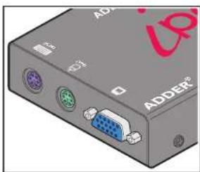
natural_image
Close-up of a gray electronic device with ports and connectors (no readable text or symbols)Connections to computer
Link these connectors to the keyboard, video and mouse ports of the computer system to be remotely controlled.
Non Dual Access model
The standard iPEPS module lacks the connectors to attach a local keyboard, video monitor and mouse, resulting in a slimmer casing.
IP network port
This intelligent Ethernet port can automatically sense whether it is attached to a 10Mb or 100Mb network.

Indicators
These six indicators clearly show the key aspects of operation:
- LNK Network link and activity indication.
- REM Keyboard or mouse data are being received from a remote viewer.
• VNC Indicates that a remote viewer is connected and active.
• 100 Indicates the Ethernet network speed (10/100Mbs).
- LOC Keyboard or mouse data are being received from the local console (or the USB Configuration Disk feature is in use).
• PWR Power indicator.
Switches
Used to select power options and invoke configuration mode

What's in the box
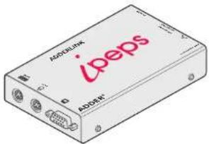
iPEPS standard model
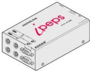
iPEPS dual access model

Rack bracket (supplied only with the standard iPEPS model)

natural_image
Isometric view of a flat rectangular plate with a faint abstract line pattern on top (no text or symbols)Information wallet
containing:
Four self-adhesive rubber feet
Safety document

natural_image
Diagram of a KVM cable set with two blue connectors and multiple purple connectors (no text or symbols on the cables themselves)
USB converter plugs
What you may additionally need

natural_image
Illustration of two blue VGA connectors with attached cable links (no text or symbols)KVM cables
One set per connected computer Part number: VKVM xV (where x is the cable length in metres: 1, 2, 5 or 10)
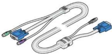
natural_image
Illustration of a U-shaped cable with blue connectors and connectors, no text or symbols presentCCSUN converter
Required to connect Sun computers that use a mini-DN port, in connection their keyboard and mouse Part number: CCSUN-xM (where x is the cable length in metres: 2.5 or 10;

natural_image
Line drawing of a multi-pin electrical connector with leads (no text or symbols)Squid power cable
Allows up to four iPEPS units to be powered from a single power adapter Part number: CAB-XSERIES-4WAY-PWR
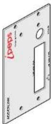
iPEPS Dual Access rack plate
Part number: NET-PEPS-DA-FASCIA

Installation
Mounting
The iPEPS offers two main mounting methods:
• Supplied four self-adhesive rubber feet
- Rack mount brackets - see below
Connections

An extra width rack bracket is available as an optional extra for the iPEPS Dual Access model.
A rack bracket is supplied with each iPEPS standard model.

Connections
Installation of the iPEPS involves a number of basic connections to some or all of the following items:
- Host computer (below)
- Local keyboard, video and mouse
• IP network port
• Power supply
Host computer
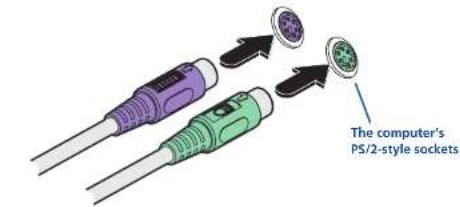
The iPEPS is connected to the host computer using the supplied KVM cable. At the computer end of the cable you have the choice of linking the cable's PS/2 connectors directly to the computer or additionally attaching the supplied USB converters. The converters not only allow you to use the computer's USB sockets but also enable the Adder Virtual Media feature to be used.
To attach the KVM cable to the iPEPS
1 Ensure that power is disconnected from the iPEPS and the computer.
(Note: If it is not possible to switch off the computer prior to connection, then a 'Hot plug' procedure is available – see the Hot plugging and mouse restoration section for more details).
2 Connect the plugs at one end of the KVM cable set to the three sockets at one end of the iPEPS. On the Dual Access model these are the ones on the bottom row.

To attach the KVM cable to the computer
1 Connect the video connector of the KVM cable to the video output socket of the computer.
2 The keyboard and mouse connections can be made to the computer in two main ways:
- Directly to PS/2-style keyboard and mouse sockets of the computer.
or
• Via the supplied converters, to the USB connectors of the computer.

When used in this way, the keyboard and mouse signals are both fed via the green USB converter (and lead).
Note: If you intend to power the iPEPS from the keyboard/mouse interface (rather than a power adapter) both the purple and the green connections must be made to the computer. This is true regardless of whether you use the PS/2 connections or the USB converters. The iPEPS will prevent power being taken from just one socket in order to prevent overloading.

Local keyboard, video monitor and mouse
Note: Dual Access model only
Where local control is required (as well as remote control), the iPEPS Dual Access model provides the necessary keyboard, video and mouse console outputs.
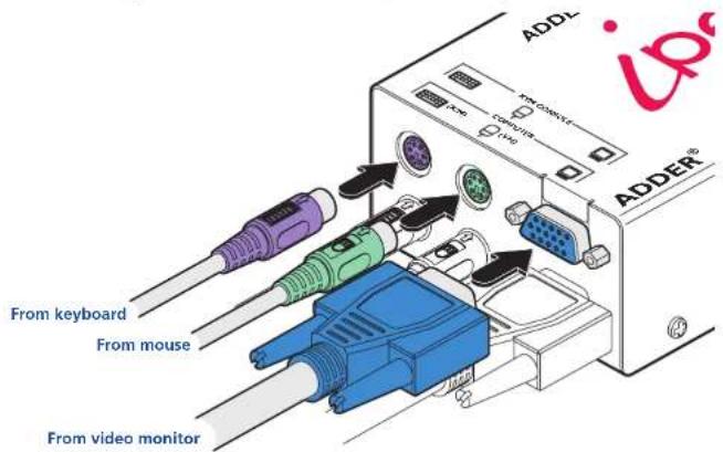
To connect a local keyboard, video monitor and mouse
1 Position a suitable keyboard, video monitor and mouse in the vicinity of the iPEPS such that their cables will easily reach.
2 Connect the keyboard, video monitor and mouse plugs to the sockets, collectively labelled as 'KVM CONSOLE', on the end panel of the iPEPS.
IP network port
The iPEPS provides an autosensing Ethernet IP port that can operate at 10 or 100Mbps, according to the network speed. The iPEPS is designed to reside quite easily at any part of your network:
- It can be placed within the local network, behind any firewall/router connections to the Internet, or
- It can be placed externally to the local network, on a separate sub-network or with an open Internet connection.
Wherever in the network the iPEPS is situated, you will need to determine certain configuration issues such as address allocation and/or firewall adjustment to allow correct operation. Please refer to Networking issues within the Configuration chapter for more details.
IMPORTANT: When the iPEPS is accessible from the public Internet, you must ensure that sufficient security measures are employed.
To connect the IP network port
1 Depending upon where in the network the iPEPS is being connected, run a category 5e or 6 cable from the appropriate hub or router to the iPEPS.
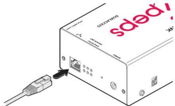
2 Connect the plug of the category 5e or 6 cable into the IP port on the end panel of the iPEPS.

3 Configure the network settings as appropriate to the position of the iPEPS within the network - see Networking issues for details.

Power supply connection
The iPEPS provides flexibility in the way that it is powered in order to suit your installation requirements. Each iPEPS can be powered:
• Via the keyboard and mouse connections from the host computer,
• From an individual power adapter, or
• From a common power adapter (when used with other iPEPS units).
Power supply issues and options
If you intend to derive power from the keyboard and mouse connections, then both connections must be made to the host computer. The power requirement of the iPEPS slightly exceeds the maximum that is permissible via a single keyboard, mouse or USB port. Therefore, the iPEPS will share its requirements between two ports and will automatically refuse to operate if only one connection is made.
The iPEPS draws a maximum current of 1A at 5VDC. If your computer cannot provide the necessary power requirement (via its keyboard, mouse or USB ports) then you will need to use an external power adapter and also prevent the iPEPS from deriving any of its power from the ports. On the side panel of the iPEPS, use switch 1 to determine how power should be derived:
SW1 OFF Derive iPEPS power from either the interface connections or an external power supply.
ON Derive iPEPS power only from the external power adapter.

To connect the optional power adapter
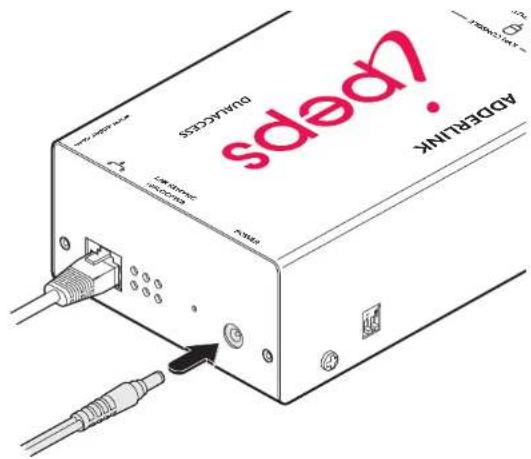
1 Connect the low voltage output connector from the power supply unit to the power socket on the end panel of the iPEPS. Note: Ensure that switch 1 is set to the appropriate setting for your installation - see 'Power supply issues and options' opposite.
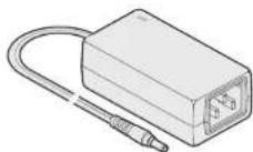
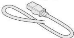
2 Connect the IEC connector of the supplied country-specific power lead to the socket of the power supply.
3 Connect the power lead to a nearby mains supply socket.
continued

To use a common power adapter to supply multiple iPEPS units
Available as an optional item, the Adder Power Squid cable allows you to distribute power from an adapter to a maximum of four iPEPS units.
Note: Do not attempt to power more than two iPEPS units using the standard 5V 2A power adapter unit. For three or four iPEPS, use only the higher capacity 5V 4A adapter.
1 Connect a power output plug of the squid cable to the input socket of each iPEPS unit.
Note: Ensure that switch 1 on each iPEPS is set to the appropriate setting for your installation - see Power supply issues and options on the previous page.
2 Connect the low voltage output connector from the power supply unit to the input socket of the power spider cable.
3 Connect the IEC connector of the supplied country-specific power lead to the socket of the power supply.
4 Connect the power lead to a nearby mains supply socket.


Configuration
Initial configuration
The iPEPS initial configuration process occurs as two distinct parts. The standard iPEPS and the Dual Access models differ in Part 1 of their configuration, but behave in an identical manner for the Part 2 configuration.
Part 1 – Initial configuration
This part of the configuration takes place using either a locally connected keyboard and video monitor (Dual Access model only) or a computer connected to the same local network as the iPEPS. It allows you to set up key basic details, network essentials and security key creation.
Part 1 - Initial configuration (Dual Access model)
When controlled via the locally connected keyboard and video monitor, as the iPEPS Dual Access model is switched on for the first time it will take you through a set up sequence consisting of three main screens:
OR
Part 2 - Remote configuration
This part of the configuration takes place using a remote network connection. It allows fine tuning of the part 1 configuration items plus the creation of multiple user accounts. Go to Part 2 - Remote configuration.
Part 1 – Initial configuration (Standard or Dual Access models)
Connect the iPEPS to an IP network and use a computer located on the same network to connect to the iPEPS. See page 16 for details.
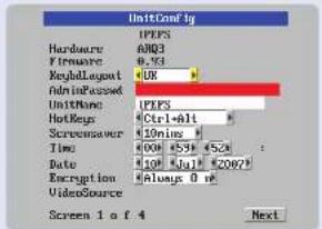
Unit config screen
Allows you to determine a mixture of basic and fundamental setup details such as the keyboard layout, admin password, time and date.

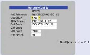
Network config screen
Requires you to configure the various key aspects of the IP network port addressing.

Secure keys screen
This screen uses your mouse movements or keyboard inputs to create random data. This unpredictable information is then combined with several other factors to develop the basis of the encryption keys that are used to establish secure remote links.

continued
Controlling the local configuration menus
The local menus use only the keyboard. Use the keyboard arrow keys to move the green highlight indicator to the required position. Then, either type the required information or use the left and right arrows to change multiple choice items, as appropriate.
Problems?
The iPEPS asks for an unknown admin password

Part 1 - Initial configuration (Dual Access model)
To perform the initial local configuration (Dual Access model only)
1 Edit the Unit config screen. The key elements here are:
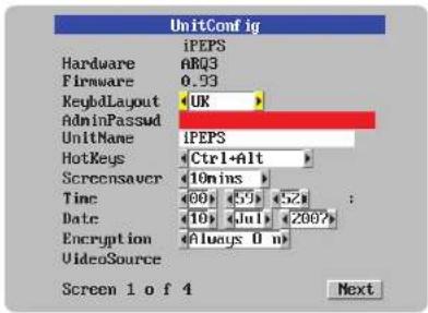
Admin password
Enter a password of at least 8 characters, including at least 1 letter, 1 number and a special character. The background colour provides an indication of password suitability and is initially red to indicate that the password is not sufficient. When a password with reasonable strength has been entered it changes to blue.
Time and Date
Set these correctly as all entries in the activity log are time stamped using them.
Encryption
Arrange this setting according to your security requirements. See Encryption settings for a description of the issues and the settings.
When all items are correct, select the Next option to display the next screen.
2 Edit the Network config screen. The key elements here are:

Use DHCP/IP address/Net Mask/Gateway
You need to either set the DHCP option to 'Yes' or manually enter a valid IP address, Net mask and Gateway. See Networking issues for more details.
VNC and HTTP ports
These should remain set to 5900 and 80, respectively, unless they clash with an existing setup within the network. See Networking issues for more details.
When all items are correct, select the Next option to display the next screen.
3 Move the mouse and enter changing key sequences within this screen.

With every mouse move and keypress, the single dash will move across the screen (unless the same key is pressed repeatedly). Periodically, a new star character will be added to the bar as the random data are accepted as part of the new encryption key. When the bar is full, the final encryption keys for your iPEPS will be created – this process takes roughly 30 to 40 seconds.
4 Once the secure keys have been calculated the iPEPS will restart and present a standard logon screen.

At this stage the username will be 'admin' and the password will be whatever you entered in the first setup screen.
Once the username and password have been accepted, the screen should now show the host computer screen (or, if none is connected, a blank image).
continued

5 To view the options menu: Press Ctrl Alt C. More about hotkeys. (if the standard hotkeys were altered, use the new hotkeys plus C)

Access mode
Allows you to choose between Shared mode (where all other logged on users can see your operations) and Private mode (where the screens of all other users are blanked).
Logoff
Select to close your current session and display the screensaver.
Restore mouse functions
Select to revive a mouse that has ceased to function correctly. See Hot plugging and mouse restoration for details.
Configuration
Select to gain access to the Unit and Network configuration screens. Within here you can also reset the iPEPS to its initial state.
Return to host
Quits the menu and returns to the host screen.
Encryption settings
The iPEPS offers a great deal of flexibility in its configuration and this extends equally to its encryption settings. Due to the variety of situations in which it might be used and the range of viewer applications that need to view it, a number of settings are available that might not make perfect sense at first glance. However, these settings should allow you to configure the iPEPS and the viewers to operate as required.
Factors to consider when setting these options might be:
• Do all of the connections and operations require encryption?
• Will some users be using older VNC viewer versions?
iPEPS encryption settings
The iPEPS configuration page offers three encryption settings:
- Always on - This setting will force all viewers to use encryption. Note: This setting will preclude any VNC viewer versions that do not support encryption.
- Prefer off - This setting does not enforce encryption unless a viewer specifically requests it. If a viewer has its 'Let server choose' setting, then an un-encrypted link will be set up.
- Prefer on - This setting generally enforces encryption unless an earlier viewer version is unable to support it, in which case the link will be unencrypted. If a viewer has its 'Let server choose' setting, then the link will be encrypted.
Viewer encryption settings
The web browser viewers and VNC viewers (of level 4.0b5S or higher) offer four encryption settings:
- Always on - This setting will ensure that the link is encrypted, regardless of the iPEPS encryption setting.
- Let server choose - This setting will follow the configuration of the iPEPS. If the iPEPS has 'Always on' or 'Prefer on' set, then the link will be encrypted. If the 'Prefer off' setting is selected at the iPEPS, then the link will not be encrypted.
- Prefer off - This setting will configure an un-encrypted link if the iPEPS will allow it, otherwise it will be encrypted.
- Prefer on - If the iPEPS allows it, this setting will configure an encrypted link, otherwise it will be un-encrypted.

Hot plugging and mouse restoration
It is strongly recommended that you switch off the host computer before attempting to connect it to the iPEPS. However, if this is not possible then you need to 'hot plug' the computer while it is still running. There is not normally a danger of damage to the computer, however, when mouse communications are interrupted, often they fail to re-initialise when reconnected. The iPEPS provides a feature to reinstate mouse communications once the necessary connections have been made.
There are two main types of data formats used by current PC mice, these are the older 'PS/2' format and the more recent 'IntelliMouse®' format introduced by Microsoft. These use slightly different data arrangements and it is important to know which type was being used before you hot-plugged the computer to the iPEPS. The previous setting depends both on the type of mouse and the type of driver, as various combinations of PS/2 and IntelliMouse are possible. Using the incorrect restore function may produce unpredictable results and require the computer to be re-booted.
Which restore setting do I use?
The general rule is that unless both the mouse and the driver are both IntelliMouse compatible then you need to restore the mouse as 'PS/2'. An IntelliMouse can operate in either mode, whereas a PS/2 mouse cannot.
Recognising an IntelliMouse-style mouse
The IntelliMouse format was introduced to support, among other features, the scroll wheel function. If the mouse has a scroll wheel, then it is likely to support the IntelliMouse format. If it is a Microsoft-branded mouse, then it will usually state that it is an IntelliMouse on its underside label.
Recognising an IntelliMouse driver
Before hot plugging to the iPEPS (or afterwards using only keyboard control), access the Windows Control Panel of the computer and select either the Mouse option (on Windows NT, 2000 and XP) or the System option (on Windows 95, 98, ME). Look for the name of the driver, which will usually include the words PS12 or IntelliMouse.
To restore mouse operation when hot plugging:
1 Carefully make the keyboard, monitor and mouse connections between the host computer and the iPEPS ports.
2 Using a keyboard and monitor directly connected to the iPEPS, log on and then press CM Alt C to view the options menu. More about hotkeys
3 Select the 'Restore mouse functions' option to display:

4 Select one of the following options:
- Restore PS/2 Mouse – if PS/2 mode is required, or
- Restore IntelliMouse – if IntelliMouse mode is required.
5 Select the 'Return to host' option.
6 Move the mouse a short distance and check for appropriate on-screen cursor movement. If the mouse cursor darts erratically around the screen, then cease moving the mouse. This is an indication that the chosen restore function is incorrect. Try again using the other restore function.
Note: The restore functions predict the likely mouse resolution settings but may not restore the exact speed or sensitivity settings that were originally set.

Resetting the configuration (Dual Access models only)
The iPEPS does not display the configuration sequence
If the iPEPS has been previously configured it may not automatically display the first of the setup screens. In this case you have two options, either:
- Access the Unit or Network configuration screens separately, or
- Reset the configuration:
To invoke a configuration reset by main menu
1 Using the locally connected keyboard and screen, log on as the admin user.
2 Select the 'Configuration' option.
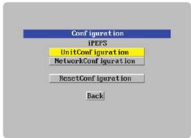
flowchart
graph TD
    A["Configuration"] --> B["iPEPS"]
    B --> C["UnitConfiguration"]
    C --> D["NetworkConfiguration"]
    D --> E["ResetConfiguration"]
    E --> F["Back"]
3 Highlight the 'Reset configuration' option and press
A warning screen will be displayed, select the RESET option and press

4 The iPEPS will reset and then display the first of the four initial configuration screens.

Part 1 – Initial configuration (Standard or Dual Access models)
To perform the initial local configuration
1 Connect the iPEPS to an IP network where a suitable computer is available on the same subnet (please see the Installation chapter for further details).
2 Use a computer connected to the same subnet of the network. On that computer, locate and select the VNC viewer icon A connection details dialog will be displayed:

VNC Viewer
![VNC Viewer : Connection Details Server: 152.168.143 Encryption: Let Server Choose (Default) Options button Enter the iPEPS address here and click OK If required, select the encryption mode - MORE [+] Provides a range of viewer and connection settings - MORE [+]](/content/2026/05/901927/images/bed1160abd302957592090c5ac24ece2b7ad9f0a9698f1f8644e11c81f08168d.jpg)
3 In the 'Server:' entry, type the address: 192.168.1.42
4 Click the OK button. Depending on the options selected, you may need to confirm certain items. A connection attempt will be made and if successful, an authentication dialog will be displayed:

5 Enter admin as the Username, leave the password entry blank and click the OK button. You will now be prompted to enter a new password before the Viewer window opens:

If the iPEPS does not respond, then please see the next page for details of actions that you can take.
6 Click the Configure button to display the Configuration menu:
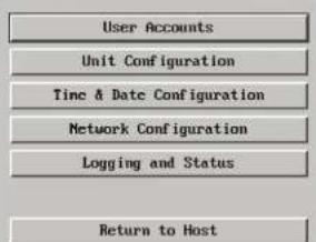
You are now ready to begin Part 2 of the configuration. Use the various options (particularly the 'Unit Configuration' and 'Network Configuration' options) to arrange the iPEPS to suit your requirements.

If the iPEPS does not respond on the network
If the iPEPS fails to respond when you attempt to access it on a local network (as discussed on the previous page), the most likely cause (presuming that it is correctly connected) is that it has been re-assigned to use network settings other than the default values.
In such cases, you can remedy the situation in either of two ways, either:
- Reset the iPEPS back to its default network settings using the reset procedure (shown below),
or
- Set the iPEPS to any required network settings using a USB link (shown right) ➕.
To reset the iPEPS to its default network settings
If the iPEPS network address has been previously changed from its factory default, then it won't respond when you try to make initial contact. You can reset it to its default address (192.168.1.42) and other settings by performing the following:
1 Remove all power to the device.
2 Set switch 2 on the side of the unit to its ON position.
3 Apply power to the device. After about two seconds the VNC indicator will light. Before the indicator extinguishes, insert a thin object (such as a straightened paperclip) into the small hole adjacent to the power socket to depress the concealed reset switch and then remove it.
4 Shortly after, the VNC light should flash five times. This indicates that the reset operation has been successful.
5 Remove power and return switch 2 on the side of the unit to its OFF position.

To alter the iPEPS network settings via USB connection
This method allows you to configure the basic iPEPS network settings before it has been connected to any network. To achieve this task, you need to connect the iPEPS to a computer that uses Windows 2000, XP or Vista.
1 Remove all power to the device and set switch 2 on the iPEPS unit to 'ON'.
2 Connect the iPEPS mouse port to a vacant USB socket on your computer using the supplied KVM cable and green USB converter plug as shown in the Host Computer connections section. Note: If you also connect the keyboard cable and purple converter then the iPEPS can derive power from the computer.
3 Power up the iPEPS unit and the computer (if not already switched on).
4 The Windows computer should report that a 'New Disk' has been inserted. Use Windows Explorer to browse to the new disk and locate the file 'config.txt'. Edit this file using an editor such as Notepad or Wordpad:
| Configuration File |
| # |
| #Edit and save this file. Close editor before safely removing USB mass storage device. |
| #Wait 10 seconds after disconnecting USB lead for configuration to happen. |
| #Lines beginning with a '#' are comments |
| #All other lines should be of the form: Parameter=Value |
| #DO NOT USE SPACE OR TABS |
| #IP Address for device |
| lpAddress=192.168.1.42 |
| #IP sub-network mask |
| lpNetMask=255.255.0.0 |
| #Gateway for subnet |
| lpGateway= |
| #Whether to use DHCP on device 1=true, 0=false |
| UscDHCP=0 |
| #Set to '1' to reset password |
| resetAdminPasswd=0 |
5 Edit the parameters in this file as required, then save the file.
6 IMPORTANT: In the Windows Explorer 'File' menu, choose the 'Eject' option in order to prompt the iPEPS to use the new information. Wait a couple of seconds to ensure that this action has been completed.
7 Disconnect the USB cable from the computer.
8 Wait for ten seconds and then power down the unit.
9 Return Switch 2 to its 'OFF' position.
10 The iPEPS unit configuration should have been set with the new information that you provided in the config.txt file. If necessary, you can confirm that this has happened by repeating these steps to check the contents of the "config.txt" file.

Part 2 - Remote configuration
The second part of the configuration requires you to log into the iPEPS from a system via a network connection using either of the following two access applications:
- The VNC viewer – a small application downloadable from the Adder and RealVNC websites or even downloadable from the iPEPS itself.
or - A standard browser that supports Java – As soon as a web browser makes contact, the iPEPS downloads a Java application to it. This allows a viewer window to be opened and operation to commence just as it would with the VNC viewer application.
User accounts Allows you to create and manage up to sixteen separate user accounts, each with separate access permissions.
Unit configuration
Allows you to alter both basic and fundamental
settings within the iPEPS.
Time & Date Configuration
Allows you to set the current time and date as well as the timezone specifier and specify a network timeserver, if necessary
Network configuration
Here you can alter any of the existing network settings plus you can take advantage of the IP access control feature that lets you to specifically include or exclude certain addresses or networks.
Logging and status
Provides various details about the user activity on the iPEPS.
To perform the remote configuration
1 Use either the VNC viewer or a standard web browser to make remote contact with the iPEPS – see Connecting to the iPEPS for more details.
2 If the username entry is not blanked out, enter 'admin'. Then enter the password that was set during the local configuration stage. Once logged in, the iPEPS will show the video output from the host system (if one is connected), or otherwise a 'No Signal' message.
3 Click the Configure button in the top right hand corner of the window to display the configuration menu ↓

Several of the options within the configuration menu duplicate those that are available in the local configuration (Dual Access model only). However, there are other settings that are only available here.
For more information about each menu option, please see Appendix 5 - Remote configuration menus in the 'Further information' chapter.

Networking issues
Thanks to its robust security the iPEPS offers you great flexibility in how it integrates into an existing network structure. The iPEPS is designed to reside either on an internal network, behind a firewall/router or alternatively with its own direct Internet connection.
Positioning iPEPS in the network
Every network setup is different and great care needs to be taken when introducing a powerful device such as the iPEPS into an existing configuration. A common cause of potential problems can be in clashes with firewall configurations. For this reason the iPEPS is designed to be intelligent, flexible and secure. With the minimum of effort the iPEPS can reside either behind the firewall or alongside with its own separate Internet connection.

flowchart
graph TD
    A["Internet"] --> B["Firewall/ router"]
    B --> C["KVM link to host system"]
    C --> D["iPEPS situated behind the firewall"]
    D --> E["Local network connection"]
    E --> B
flowchart
graph TD
    A["Internet"] --> B["Firewall/ router"]
    B --> C["Local network connection"]
    C --> D["iPEPS situated alongside the firewall"]
    D --> E["KVM link to host system"]
    E --> F["Firewall/ router"]
    F --> G["Local network connection"]
    G --> H["iPEPS"]
IMPORTANT: When the iPEPS is accessible from the public Internet or dial up connection, you must ensure that sufficient security measures are employed.
Placing iPEPS behind a router or firewall
A possible point of contention between the iPEPS and a firewall can occasionally arise over the use of IP ports. Every port through the firewall represents a potential point of attack from outside and so it is advisable to minimise the number of open ports. The iPEPS usually uses two separate port numbers, however, these are easily changeable and can even be combined into a single port.
IMPORTANT: The correct configuration of routers and firewalls requires advanced networking skills and intimate knowledge of the particular network. Adder Technology cannot provide specific advice on how to configure your network devices and strongly recommend that such tasks are carried out by a qualified professional.
Port settings
As standard, the iPEPS uses two ports to support its two types of viewer:
• Port 80 for users making contact with a web browser, and
• Port 5900 for those using the VNC viewer.
When these port numbers are used, VNC viewers and web browsers will locate the iPEPS correctly using only its network address. The firewall/router must be informed to transfer traffic, requesting these port numbers, through to the iPEPS.
When a web server is also on the local network
Port 80 is the standard port used by web (HTTP) servers. If the iPEPS is situated within a local network that also includes a web server or any other device serving port 80 then, if you want to use the web browser interface from outside the local network environment, the HTTP port number of the iPEPS must be changed.
When you change the HTTP port to anything other than 80, then each remote browser user will need to specify the port address as well as the IP address. For instance, if you set the HTTP port to '8000' and the IP address is '192.168.47.10' then browser users will need to enter:
http://192.168.47.10:8000
(Note the single colon that separates the IP address and the port number). The firewall/router would also need to be informed to transfer all traffic to the new port number through to the iPEPS.
If you need to change the VNC port number
If you change the VNC port to anything other than 5900, then each VNC viewer user will need to specify the port address as well as the IP address. For instance, if you set the VNC port to '11590' and the IP address is '192.168.47.10' then VNC viewer users will need to enter:
192.168.47.10::11590
(Note the double colons that separate the IP address and port number). The firewall/router would also need to be informed to transfer all traffic to the new port number through to the iPEPS.

Addressing
When the iPEPS is situated within the local network, you will need to give it an appropriate local IP address and IP network mask. This is achieved most easily using the DHCP server option which will apply these details automatically. If a DHCP server is not available on the network, then these details need to be applied manually in accordance with the network administrator.
The firewall/router must then be informed to route incoming requests to port 5900 or port 80 (if available) through to the local address being used by the iPEPS.

flowchart
graph TD
    A["Internet"] --> B["Firewall/router address: 129.7.1.10"]
    B --> C["Remote user with VNC viewer accesses IP address: 129.7.1.10 and automatically uses port 5900."]
    B --> D["iPEPS has a local address and net mask, i.e."]
    B --> E["IP address: 192.168.0.3"]
    B --> F["Net mask: 255.255.255.0"]
To discover a DHCP-allocated IP address
Once a DHCP server has allocated an IP address, you will need to know it in order to access the iPEPS via a network connection. To discover the allocated IP address:
1 In either the local or remote Network configuration screens, set the 'Use DHCP' option to 'Yes' and select 'Save'. Once the page is saved, the iPEPS will contact the DHCP server and obtain a new address.
2 Re-enter the same 'Network configuration' screen where the new IP address and network mask should be displayed.
DNS addressing
As with any other network device, you can arrange for your iPEPS to be accessible using a name, rather than an IP address. This can be achieved in two main ways:
- For small networks that do not have a DNS (Domain Name System) server, edit the 'hosts' files on the appropriate remote systems. Using the hosts file, you can manually link the iPEPS address to the required name.
- For larger networks, declare the IP address and required name to the DNS server of your local network.
The actual steps required to achieve either of these options are beyond the scope of this document.

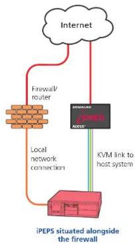
Placing iPEPS alongside the firewall
iPEPS is built from the ground-up to be secure. It employs a sophisticated 128bit public/private key system that has been rigorously analysed and found to be highly secure (a security white paper is available upon request from Adder Technology Ltd). Therefore, you can position the iPEPS alongside the firewall and control a computer that is also IP connected within the local network.
IMPORTANT: If you make the iPEPS accessible from the public Internet, care should be taken to ensure that the maximum security available is activated. You are strongly advised to enable encryption and use a strong password. Security may be further improved by restricting client IP addresses, using a non-standard port number for access.
Ensuring sufficient security
The security capabilities offered by the iPEPS are only truly effective when they are correctly used. A weak password or unencrypted link can cause security loopholes and opportunities for potential intruders. For network links in general and direct Internet connections in particular, you should carefully consider and implement the following:
- Ensure that encryption is enabled.
By local configuration or by remote configuration. - Ensure that you have selected secure passwords with at least 8 characters and a mixture of upper and lower case and numeric characters, plus a special character. By remote configuration.
- Reserve the admin password for administration use only and use a non-admin user profile for day-to-day access.
- Use the latest Secure VNC viewer (this has more in-built security than is available with the Java viewer). To download the viewer.
• Use non-standard port numbers. - Restrict the range of IP addresses that are allowed to access the iPEPS to only those that you will need to use. To restrict IP access.
• Do NOT Force VNC protocol 3.3. Remote configuration. - Ensure that the computer accessing the iPEPS is clean of viruses and spyware and has up-to-date firewall and anti-virus software loaded that is appropriately configured.
- Avoid accessing the iPEPS from public computers.
Security can be further improved by using the following suggestions:
- Place the iPEPS behind a firewall and use port the numbers to route the VNC network traffic to an internal IP address.
• Review the activity log from time to time to check for unauthorized use. - Lock your server consoles after they have been used.
A security white paper that gives further details is available upon request from Adder Technology Limited.
Ports
In this configuration there should be no constraints on the port numbers because the iPEPS will probably be the only device at that IP address. Therefore, maintain the HTTP port as 80 and the VNC port as 5900.
Addressing
When the iPEPS is situated alongside the firewall, it will require a public static IP address (i.e. one provided by your Internet service provider).
More addressing information:
Discover DHCP-allocated addresses
DNS addressing

Operation
Connecting to the iPEPS
The iPEPS offers you two ways to connect:
- Local connection (Dual Access models only),
• Remote connection by network link,
...and two types of viewer:
• VNC viewer,
• Standard web browser.
Local connection (dual access models only)
The keyboard, video monitor and mouse connected directly to the iPEPS dual access offer password protected access to the host computer.
To make a local connection:
1 Using the keyboard connected directly to the IPEPS dual access, press any key to exit the screensaver and display the logon prompt.

2 Enter your username and password. Providing you have the correct permissions, the screen will display the currently selected host computer.
To view the local control menu
1 Press and hold the hotkeys (usually card), then press and finally release all three keys.
Note: The and keys when pressed in combination are called 'hotkeys' and they signal to the iPEPS that you wish to control it, rather than the host computer. However, if these particular hotkeys clash with another device or program, then your administrator may change them to a different combination. If the combination fails to work, then please contact the system administrator for details.

The local control menu contains numerous options, the most useful of which are:
- Access mode - Allows you to select a 'Private' mode in order to prevent other logged on users from viewing your actions on the host computer. Use □ and □b change between modes. Note: For the courtesy of other users, this mode should be used sparingly. The admin user has the ability to overrule the private setting.
- Return to host - Quits the control menu and displays the host computer screen.

Local connection (continued)
To avoid the 'hall of mirrors' effect
IMPORTANT: Never configure a system so that your viewer is viewing itself. When controlling a host computer using the locally connected keyboard, video monitor and mouse, it is possible to use the VNC viewer or a browser (if the host computer is networked) to create a remote link back to itself. This will set up a 'hall of mirrors' effect, where the computer is viewing itself into infinity. While technically possible, the iPEPS unit is not designed to withstand this treatment and could sustain damage.
Remote connections
From a remote system, you connect to the iPEPS using either of two types of viewer:

flowchart
graph TD
    A["VNC viewer"] --> C["Internet"]
    B["Web browser"] --> C["Internet"]
    C --> D["ADDERLINK /peps"]
    D --> E["ADDER"]
    E --> F["Red Box"]
    style A fill:#f9f,stroke:#333
    style B fill:#f9f,stroke:#333
    style C fill:#ccf,stroke:#333
    style D fill:#cff,stroke:#333
    style E fill:#ffc,stroke:#333
    style F fill:#cfc,stroke:#333

Remote connection by VNC viewer
The VNC viewer is a compact application that runs on your remote system and allows you to view and use the iPEPS and its host computer. VNC viewer is readily available from sources such as:
• from the iPEPS itself
• from the RealVNC website
To connect using the VNC viewer
1 Locate and select the VNC viewer icon ⇒

VNC Viewer
A connection details dialog will be displayed:
![VNC Viewer : Connection Details Server: 192.168.3.1 Encryption: Let Server Choose (Default) OK Options button Provides a range of viewer and connection settings - MORE [+] Enter the iPEPS address here and click OK If required, select the encryption mode - MORE (+)](/content/2026/05/901927/images/b545e0766f1dfbbfd8b2fbf3c5d695b250d18a9c3b18222b133e2690128e692f.jpg)
2 In the 'Server:' entry, type the address of the iPEPS as follows:
v.w.x.y
where v.w.x.y is the IP network address, for example 192.168.0.3
• If you have been asked to also enter a port number.
3 Click the OK button. Depending on the options selected, you may need to confirm certain items. A connection attempt will be made and if successful, an authentication dialog will be displayed:

4 Enter your username and password. The viewer window should now open and show the current host computer. Note: If the Username entry is blanked out then only admin user account is currently defined and only a password is required.

Remote connection by Web browser
You can use a standard Web browser (supported versions) to gain access to the iPEPS and its host computer. As soon as you make contact with the iPEPS it will begin downloading a small Java application to your browser, which will be used only for the duration of your connection.
To connect using your Web browser
1 Launch your standard Web browser as usual.
2 In the Address section, type the address of the iPEPS as follows:
http://v.w.x.y
where v.w.x.y is the IP network address, for example 192.168.0.3
• If you have been asked to also enter a port number.
3 Press A connection attempt will be made. In the browser window, select the 'Connect using built-in Java VNC viewer' option to download a small application that will temporarily empower your browser (on slow connections the application download can take several tens of seconds to complete). Once complete, a connection details dialog will be displayed:

The previously entered iPEPS address will be shown here If required, select the encryption mode - MORE [+]
Options button
Provides a range of viewer and connection settings - MORE (+)
4 Make any necessary option/encryption changes and click the OK button to proceed. Depending on the options selected, you may need to confirm certain items.
5 A second connection attempt will be made and if successful, an authentication dialog will be displayed:

6 Enter your username and password. The viewer window should now open and show the current host computer. Note: If the Username entry is blanked out then only admin user account is currently defined and only a password is required.

Using the viewer window
The viewer window gives you the ability to view and control the iPEPS and its host computer. Its operation is almost identical regardless of whether you used the VNC viewer or your Web browser to display it.
The menu bar
The viewer window presents a menu bar similar to that shown below. Certain items within the toolbar are displayed depending upon your access permissions and/or the iPEPS configuration.

When using the viewer window
What is the best screen resolution to use?
The best resolution for your computer is one that is larger than the screen of the host computer that you are viewing. This will allow you to see everything without scrolling around, as described next.
How do I navigate around a larger screen?
If the screen that you are viewing has a larger resolution than your viewing window you will need to scroll around to see all items. The viewer window allows you to 'bump scroll' (only in full screen mode). This means that when your mouse cursor bumps against the edge of the screen, the screen image will scroll across automatically.
How do I escape from full screen mode?
Press the F8 button. This button is changeable but is most often set to F8.
Why is the + button flashing red?
This happens when a new host screen is viewed (that has not been viewed before). Click the Button to perform an auto calibration for the screen and the mouse. See Auto calibrate for important information about this feature.
How do I remove traces of moved items from the screen?
When you move an item or window across the screen, sometimes it can leave unsightly trails. These are called artifacts and can be particularly prevalent when the connection speed is low. To remove artifacts, click the 'Controls' button and select the 'Refresh screen' option. See Controls.
How do I make the most of a slow connection?
The VNC viewer is slightly better suited to slower connections than the browser viewer because it offers more options. Click the Options button of the VNC viewer when entering the iPEPS address during log on.
Adjust the Threshold setting
Ensure that the video Threshold setting is set higher than the automatic setting suggests. Tweak this setting manually to ensure the best setting.
Fewer colours
Select the Low (64 colours) mode. The Very low option offers hardly any improvement and looks a lot worse.
Rate limit mouse events
When selected, this mode greatly reduces the mouse movement data that are sent to the host computer. When you move the local mouse, the remote cursor will catch up roughly once per second.

Mouse pointers
Both viewers provide a double mouse cursor to help overcome any delays caused by slow connections. When you move your mouse you will see two mouse cursors, a local one that responds immediately to your movements and a second, slower moving, cursor that represents the current mouse position at the host.

Re-synchronise mouse
If you find that your local mouse pointer and that of the host are not correctly synchronised, use this feature to re-align their movements. This operation is also selectable from the Controls menu.
To re-synchronise the mouse
1 Click the button and then click OK in the subsequent pop-up message. Note: If you find that this doesn't work, you may need to perform a mouse calibration again.
Access mode - shared/private
Up to five users can be simultaneously logged-on (four remote users plus one local user) and during normal operation, all are able to see the same view of the currently selected host. If you need to perform a sensitive task that should not be viewed by other users, you can change the access mode to Private. This action blanks the viewer window for all other logged on users.
Note: For the courtesy of other users, this mode should be used sparingly. The admin user has the ability to overrule the private setting.
To change the access mode
1 Click one of the arrow buttons adjacent to the Shared/Private indicator.


Auto calibrate
When you visit the host computer for the very first time, your viewer needs to determine the optimum video and mouse settings. The button will remind you to click it by flashing red when a new computer screen is encountered. Performing this step is important because it can help to decrease unnecessary video information being sent across the link, thus improving overall performance.
Once this has been done, the video settings for the host computer will be retained and re-used.
Note: When performing an auto calibration, ensure that the screen image is static (no moving images) and also try to remove any on-screen displays (such as host names or menus). This is because they can affect the calibration process and result in a lower overall performance level. For mouse calibration, ensure that there are no application windows located around the upper left corner of the screen. This is because as the mouse calibration takes place, the cursor may change (to match the application as it skims across the window) and this may confuse the calculation. Also ensure that the host system does not have the mouse cursor trails option enabled.
To auto calibrate the screen and/or mouse
1 Click the button to display the Calibrate options dialog:
2 Click the required action.
A progress indicator will be displayed while the necessary calculations are made.
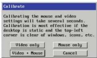
Upon completion an information dialog will explain the results:

Controls
When clicked, this button reveals a menu of options concerned with keyboard, video and mouse operation.
Single Mouse Mode
This mode is for fast network connections where the cursor response is sufficient to provide instant visual feedback on the remote screen. When enabled, the cursor is 'captured' within the viewer window until you use the 'escape' hot keys.
To escape from single mouse mode, press F8 and then P. Alternatively, enable and use the mouse button escape sequences - see Advanced unit configuration for details.
The single mouse mode does not require calibration.
Resync Mouse
This option has the same effect as the button on the menu bar and re-synchronises the local and remote mouse pointers.
Refresh Screen
This option refreshes the whole screen image to remove any artifacts from moved screen items. This is useful when using very low refresh rates on slow speed communication links.


Mouse Control
This option displays a mouse control dialog and is useful when the remote cursor is failing to respond correctly to your mouse movements, even after using the Resync mouse option.
The mouse control dialog allows you to control the remote mouse cursor using a selection of buttons that you click with your local mouse.
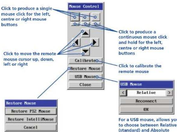
Click to display the Restore mouse dialog where you can reinstate a mouse that has failed to operate correctly.
For advice on which mouse type to choose.
For the latter, the connected host computer must support absolute positioning devices.
Keyboard Control
This option displays a keyboard control dialog and is useful for sending keyboard combinations (to the host) that are needed regularly or that are trapped by the iPEPS.
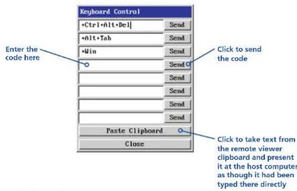
When entering codes:
- means press down the key that follows
– means release the key that follows - means press down and release the key that follows
* means wait 250ms (note: if a number immediately follows the asterisk, then the delay will equal the number, in milliseconds)
It is automatically assumed that all keys specified will be released at the end, so there is need to specify -Ctrl or -Alt if these keys are to be released together.
See Appendix 8 for a list of key sequence codes that can be used.
Examples:
'Ctrl + Alt 12' would be expressed as: +Ctrl+ Alt+1-1+2
+N means press the 'N' key
+Scroll means press the Scroll lock key
+Space means press the space key

Video Settings
This dialog provides access to all of the key video settings that determine image quality and link performance.
Phase
The phase setting adjusts the alignment of the host video output and the remote system video display to achieve the sharpest image.
Horizontal position
Determines the horizontal position of the host screen image within the viewer window.
Vertical position
Determines the vertical position of the host screen image within the viewer window.

Colour, brightness &
contrast
Provides manual sliders and also an automatic setting button to optimise these important video constituents for the current host and connection speed.
Calibrate all
Click to determine the optimum settings for all aspects of video the video connection from the host system.
Display activity
Indicates the level of video activity currently in progress.
Using automatic configurations
- Every setting can be individually subjected to an automatic configuration (click the appropriate 'Auto' button) and most can also be manually adjusted.
- Use the 'Calibrate All' button to automatically determine the optimum settings for all items.
Note: Before using the 'Calibrate All' option, if possible, remove on-screen display (OSD) elements. These OSD elements use different video rates to those of the host system and can affect the setting of the automatic threshold value. iPEPS uses an improved calculation procedure to filter out the effect of these elements. However, best results are obtained when the screen contains only host system information.
Note: To maximise performance, the threshold level is automatically increased by 50% when a slow link is detected.
Setting the Threshold manually
Occasionally it can be useful to manually adjust the Threshold setting, in order to achieve a setting that best suits your particular requirements.
1 Use the 'Calibrate All' function to ensure that all other settings are optimised.
2 Click the Threshold left arrow button to decrement the setting by one and observe the 'Display Activity' indicator.
3 Repeat step 2 until the Display Activity indicator suddenly rises to a much higher level (i.e. 50%). This will mean that you have reached the noise boundary. At this point, increment the Threshold value by 2 or 3 points to achieve an optimum setting.

Advanced Settings
This option contains video signal settings that do not normally need to be adjusted.
Pixel Format
Determines the colour depth and data required to represent each video pixel.
Motion Detection
This option is not available for use with the iPEPS.

Overlap Capture
When enabled, the iPEPS will begin capturing the next frame of video output from the host computer before it has fully completed processing the current frame. In most cases this produces better video performance, however, when moving large objects around the screen (such as an application window), the video image seen at the remote system may exhibit temporary artifacts as the large image moves.
Tile Width and Height
Determines the size of the sample areas into which the source video screen is divided for examination purposes. Smaller sizes result in more areas to sample, larger areas result in more frequent screen area refreshes. 16 is considered to be the optimum size for both the width and height settings.
Virtual Media
Please see the next page for details.
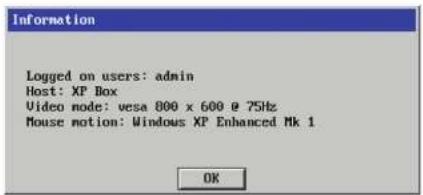
Info
When selected, this option displays an information dialog showing the current logged on users, the current host, its video mode and its mouse motion details.

Virtual Media
The Adder Virtual Media feature allows you to remotely make files available to the host computer linked to the iPEPS. Single files or collections of files and folders up to 2GB in size can be quickly transferred via the VNC link. This can prove to be an invaluable tool when upgrading the host computer from remote positions.
In order to use the Adder Virtual Media feature, the VM link must be made between the iPEPS and a USB port on the host computer. See Host computer connections for details.
To remotely transfer files to a host computer
1 On the remote system, log into the iPEPS using the VNC viewer in the usual manner.
2 On the remote system, select the file(s), folder(s) or storage device (i.e. hard drive, CD-ROM, memory stick) that you wish to transfer to the host computer (to a maximum of 2GB) in either of the following ways:
- Within the VNC viewer window, press F8 and then V. A quick scan will be made of the available storage devices and a popup similar to the following will be displayed:

Select the required storage device or file/folder, choose an appropriate 'Drive Type' (virtual CD, floppy or disk (directory)) and click OK. The selected device will be tagged for transfer but no other action will take place at this point.
- Using Windows Explorer (or the Apple Finder), locate and copy the required file, folder or drive to the clipboard.
On the remote system, within the VNC viewer window, click the Controls button and then select the Virtual Media option. A popup similar to the following will be displayed:
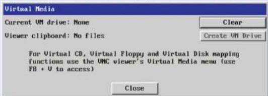
Click the 'Create VM Drive' button to announce file availability to the host computer, whereupon a popup will confirm that the new virtual media disk is built.
Note that using either of the two methods outlined above, no files or folders are transferred at this point, instead the iPEPS will simulate a removable storage device at host computer. This will appear within Windows Explorer or Apple Finder exactly as a floppy disk, removable drive or memory stick would.
3 On the host computer (either directly from iPEPS local console or via the VNC viewer) locate the new virtual drive and access the files as necessary. Files will be transferred to the host computer as they are specifically requested by the actions of the host computer.

Downloading VNC viewer from the iPEPS
The iPEPS has the ability to distribute its own VNC viewer application.
To download the VNC viewer
1 Open your Web browser.
2 Enter the network address where the iPEPS is situated (in the form: http://192.168.0.3) and make the link.
3 In the opening iPEPS screen, click the link that offers to download the secure VNC viewer 'from the unit'.
4 Save the download file (vncviewer.exe) to your system.
5 Select and run the downloaded file and then connect to the iPEPS using the VNC viewer application.
If you need to enter a port number
Usually, when you make a network connection to the iPEPS (either using the VNC viewer or a Web browser) you simply enter the IP address, i.e. 192.168.0.3. However, if a special configuration is necessary, then you may be asked to specify a port number as well as the IP address.
What is a port?
To enter a port number in a Web browser
1 Enter the required IP address in the usual Address box, i.e. http://192.168.0.3
2 At the end of the IP address, add a single colon and then enter the port number (in this example, the required port number is 8000), i.e. http://192.168.0.3:8000
3 Continue with the standard Web browser instructions.
To enter a port number in VNC viewer
1 Enter the required IP address in the usual 'Server' box, i.e. http://192.168.0.3
2 At the end of the IP address, add two colons and then enter the port number (in this example, the required port number is 11590), i.e. http://192.168.0.3::11590
3 Continue with the standard VNC viewer instructions.

Viewer encryption settings
The web browser viewers and VNC viewers (of level 4.0b5S or higher) offer four encryption options. The resulting actions of certain options depend upon how the iPEPS to which you are connecting is configured:
- Always on - This setting will ensure that the link is encrypted, regardless of the iPEPS encryption setting.
- Let server choose - This setting will follow the configuration of the iPEPS. If the iPEPS has a preference to encrypt the link, then it will be so, otherwise the link will not be encrypted.
- Prefer off - This setting will configure an un-encrypted link if the iPEPS will allow it, otherwise it will be encrypted.
- Prefer on - If the iPEPS allows it, this setting will configure an encrypted link, otherwise it will be un-encrypted.
Whenever encryption does take place, the viewer will first need to create the necessary secure key before the connection process can continue.
Supported web browsers
The following web browsers have been tested and found to work correctly with iPEPS.
Windows
- Internet Explorer 5.50 and above, with Microsoft [Java] Virtual Machine (release 5.50), with Java Runtime Environment 1.3 or above.
Linux
- Netscape 4.61 and above, with Java Runtime Environment 1.1 or above.
- Opera, with Java Runtime Environment 1.1 or above.

Further information
This chapter contains a variety of information, including the following:
• Getting assistance - see below
• Troubleshooting - see right
- Appendices
• Appendix 1 - Local configuration menus
• Appendix 2 - VNC viewer connection options
• Appendix 3 - VNC viewer window options
• Appendix 4 - Browser viewer options
• Appendix 5 - Remote configuration menus
• Appendix 6 - Addresses, masks and ports
• Appendix 7 - Cable specifications
• Appendix 8 - Hotkey sequence codes
• Appendix 9 - Supported video modes
• End user licence agreement
Getting assistance
If you are still experiencing problems after checking the information contained within this guide, then please refer to the Support section of our website:
www.adder.com
Troubleshooting
Remote network users are unable to contact the iPEPS
- Check that the correct address is being used by the remote users.
- Check the network settings. Check that the users network address has not been excluded in the IP access control section.
- If the iPEPS is situated behind a firewall, check that the relevant ports are being allowed through the firewall and are being correctly routed.
- Check the end panel indicators, the LNK indicator should be on. If the network link is a 100Mbps connection, the 100 indicator should also be on.
The remote cursor is not correctly responding to my mouse movements
- Recalibrate the mouse. When doing so, ensure that the host system does not have mouse cursor trails enabled and that the top left corner of the screen is clear of application windows.
When logging on using VNC viewer, I cannot enter a username
- Either, the VNC viewer is an old version (download a new one) or only the admin user has been configured on the iPEPS.

Appendix 1 - Local configuration menus
This section covers the control menus that are available when you are using the locally connected keyboard, video monitor and mouse.
To access the local configuration menus
On the locally connected keyboard, simultaneously press Ctrl Alt C.
Note: If the standard hotkeys (CTRL + ALT) have been changed, then you need to use those keys together with C to access the menus.
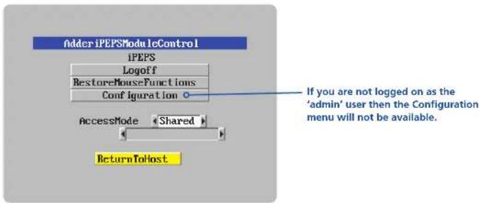
Select the 'Configuration' option to display:
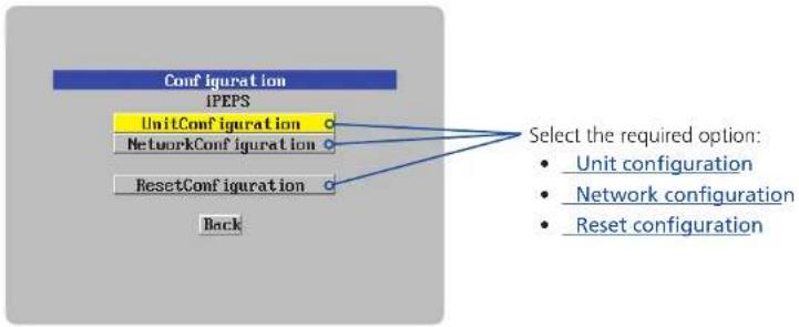
flowchart
graph TD
    A["Configuration"] --> B["iPEPS"]
    B --> C["UnitConfiguration"]
    B --> D["NetworkConfiguration"]
    B --> E["ResetConfiguration"]
    C --> F["Select the required option: Unit configuration, Network configuration, Reset configuration"]
    D --> F
    E --> F
    F --> G["Back"]

Unit configuration
This page provides access to a selection of both basic and fundamental settings for the iPEPS.
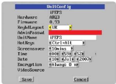
Keybd layout
Use the arrow buttons to match the keyboard layout expected by the host system.
Admin password
Enter the password that will be used to gain administrator access to the iPEPS. There can only be one admin user and only that user is given access to the configuration menus. The admin password background will be red until a reasonably secure password has been entered.
Unit name
The name entered here will be displayed on the local menus and the remote VNC/browser windows.
Hot keys
Use the left and right arrow keys to select an appropriate hot key sequence for the locally connected keyboard. This sequence is used in combination with other keypresses to access the on-screen menus. The options are: Ctrl+Alt (default), Ctrl+Shift, Alt+Shift, Alt Gr, Left + Right Alt, Left Ctrl + Alt or Right Ctrl + Alt.
To get here
1 Use the local keyboard and log on as the 'admin' user.
2 Press Off Alt G (hotkeys may be different).
3 Select 'Configuration'.
4 Select 'Unit configuration'.
Screensaver
Use the left and right arrow keys to select an appropriate period of inactivity on the local keyboard or mouse before a screensaver is displayed and the user is logged out. This setting applies to local users only and once the screensaver is displayed, for security purposes the user is required to log in again. The timeout period can be selected between 5 minutes and 1 day (24 hours) or you can choose the OFF setting to disable the screensaver feature. Note: The Idle timeout option serves a similar purpose for remote connections.
Time and date
Use the left and right arrow keys to select the correct time and date. The time entry uses the 24 hour clock notation. The internal real time clock will continue to run for roughly one week without power to the iPEPS, after that it will be lost and require resetting. Use the up and down arrow keys to move between each of the sections within the time and date entries.
Encryption
Three options are available: Always on, prefer off, prefer on. The one to choose depends on the specific details of your installation - see Encryption settings for details. The use of encryption imposes a slight performance overhead of roughly 10% but is highly secure against third party intrusion.

Network configuration
This page allows you to configure the various aspects of the IP port and its relationship with the local network.

MAC address
Media Access Control address – this is the unique and unchangeable code that was hard coded within your iPEPS unit when it was built. It consists of six 2-digit hexadecimal (base 16) numbers separated by colons. A section of the MAC address identifies Adder Technology as the manufacturer, while the remainder is effectively the unique electronic serial number of your particular unit.
Use DHCP
DHCP is an acronym for 'Dynamic Host Configuration Protocol'. Its function is particularly useful when connecting to medium size or larger networks. When this option is selected, your iPEPS will attempt to locate a DHCP server on the network. If such a server is located, it will supply three things to the iPEPS: an IP address, an IP network mask (also known as a Subnet mask) and a Gateway address. These are not usually granted permanently, but on a 'lease' basis for a fixed amount of time or for as long as the iPEPS remains connected and switched on. Discover allocations.
IP address
This is the identity of the iPEPS within a network. The IP address can be thought of as the telephone number of the iPEPS. Unlike the MAC address, the IP address can be altered to suit the network to which it is connected. It can either be entered manually or configured automatically using the DHCP option. When the DHCP option is enabled, this entry is greyed out.
Net mask
Also often called the 'subnet-mask', this value is used alongside the IP address to help define a smaller collection (or subnet) of devices on a network. In this way a distinction is made between locally connected devices and ones that are reachable elsewhere, such as on the wider Internet. This process helps to reduce overall traffic on the network and hence speed up connections in general.
To get here
1 Use the local keyboard and log on as the 'admin' user.
2 Press Ctrl Alt G (hotkeys may be different).
3 Select 'Configuration'.
4 Select 'Network configuration'.
Gateway
This is the address of the device that links the local network (to which the iPEPS is connected) to another network such as the Internet. Usually this is a network switch or router and it will be used whenever a device to be contacted lies outside the local network.
VNC port
This is the logical link through which communications with a remote VNC viewer will be channelled (see What is a port?). The default setting is 5900 which is a widely recognised port number for use by VNC software. However, in certain circumstances it may be advantageous to alter this number - see Security issues with ports for more details.
Note: The VNC port and HTTP port can be set to the same port number in order to simplify router and firewall configuration. If this is done then the iPEPS will "listen" for both types of traffic on the single port.
HTTP port
This is the logical link through which communications with a remote web browser will be channelled. The default setting of 80 is an established standard for web (HTTP - HyperText Transfer Protocol) traffic though this can be changed to suit your local network requirements.
Clear IP access control
This option removes all entries from the IP access control feature within the iPEPS. The IP access control feature (configurable by a remote admin user) allows certain network address ranges to be denied access to the iPEPS. If set incorrectly, it is possible to exclude all network users and so this option provides an emergency recovery point.

Reset configuration
This option allows you to completely reset the iPEPS.
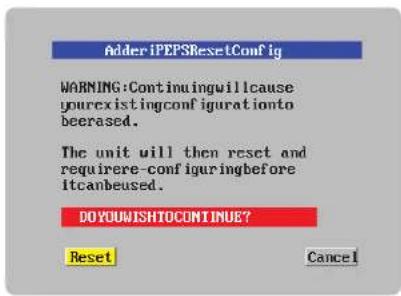
WARNING: This process will remove all settings and return the unit to use its original state. A complete reconfiguration will be required before it can be used.
To reset the iPEPS configuration
1 With the RESET option highlighted, press
2 The first screen of the initial configuration process will be displayed. See Initial configuration for details.
To get here
1 Use the local keyboard and log on as the 'admin' user.
2 Press Ctrl Alt C (hotkeys may be different).
3 Select 'Configuration'.
4 Select 'Reset configuration'.

Clear IP access control
This option removes all entries from the IP access control feature within the iPEPS.
What is IP access control?
The IP access control feature (configurable by a remote admin user) allows certain network address ranges to be denied access to the iPEPS. If set incorrectly, it is possible to exclude all network users and so this option provides an emergency recovery point.
To clear IP access control
1 Use the local keyboard and log on as the 'admin' user.
2 Press Ctrl Alt C (hotkeys may be set differently).
3 Select 'Configuration'.
4 Select 'Network configuration'.
5 Highlight the 'Clear IP access control' option and press 📄
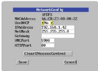

Appendix 2 - VNC viewer connection options
When you are connecting to the iPEPS using the VNC viewer, a number of options are available.

Click here to access the options
There are six tabbed pages of options:
Colour/Encoding
Auto select
When ticked, this option will examine the speed of your connection to the iPEPS and apply the most suitable encoding method. This option is suggested for the majority of installations.
Preferred encoding
There are three manually selectable encoding methods which are accessible when the Auto select option is unticked.
- ZRLE – This is a highly compressed method that is best suited to slow modem connections.
- Hextile – This method offers better performance than the ZRLE when used over a high speed network because there is no need for the iPEPS to spend time highly compressing the data.
- Raw – This is a primitive, uncompressed method that is mainly used for technical support issues. You are recommended not to use this method.

IMPORTANT: If you make any changes to the options given here and wish to retain them for successive connection sessions, you must save the changes. To do this, change to the 'Load / Save' tab and click the 'Save' button.
Colour level
This section allows you to select the most appropriate colour level for the speed of the connection to the iPEPS. Where the connection speed is slow or inconsistent there will be a necessary compromise between screen response and colour depth.
- Full – This mode is suitable only for fast network connections and will pass on the maximum colour depth being used by the host system.
- Medium (256 colours) – This mode reduces the host system output to a 256 colour mode and is more suitable for ISDN and fast modem connections.
- Low (64 colours) – This mode is suitable for slower modern connections and reduces the host system output to 64 colours.
- Very low (8 colours) – This mode provides very rudimentary picture quality and hardly any speed advantage over the 64 colour setting. You are recommended not to use this mode.

Inputs
Enable all inputs
When selected, allows keyboard, mouse and clipboard data to be transferred between server and viewer systems.
Disable all inputs (view-only mode)
When selected, prevents control data being passed between server and viewer. Viewer can display the server output, but cannot control it.
Customise
Allows you to select which data can be transferred between server and viewer.
Send pointer events to server
When un-ticked, the VNC viewer
will not send mouse movement or click data to the iPEPS or host system.
Send keyboard events to server
When un-ticked, the VNC viewer will not send keyboard information to the iPEPS or host system.
Send clipboard changes to server
This feature is restricted to software server versions of VNC and has no effect on iPEPS installations.
Accept clipboard changes from server
This feature is restricted to software server versions of VNC and has no effect on iPEPS installations, except for retrieving the activity log as described in the logging and status section.

Rate-limit mouse move events
When ticked, this feature reduces the mouse movement information that is sent to the iPEPS and host system. This is useful for slow connections and you will notice that the remote cursor will catch up with the local cursor roughly once every second.
Enable 3-button mouse emulation
This feature allows you to use a 2-button mouse to emulate the middle button of a 3-button mouse. When enabled, press the left and right mouse buttons simultaneously to create a middle button action. You are advised to generally use a 3-button mouse.
Pass special keys directly to server
When ticked, 'special' keys (the Windows key, the Print Screen key, Alt+Tab, Alt+Escape and Ctrl+Escape) are passed directly to the iPEPS rather than being interpreted locally.
Menu key
This feature allows you to select which function key is used to display the VNC viewer options menu. The menu key is only way to exit from the full screen viewer mode.
IMPORTANT: If you make any changes to the options given here and wish to retain them for successive connection sessions, you must save the changes. To do this, change to the 'Load / Save' tab and click the 'Save' button.

Scaling
No Scaling
No attempt is made to make the screen image fit the viewer window. You may need to scroll horizontally and/or vertically to view all parts of the screen image.
Scale to Window Size
Adjusts the server screen image to suit the size of the viewer window.
Custom Size
Adjusts the server screen image according to the Width and Height settings in the adjacent fields. A drop box to the right of the fields allows you to define the image size by percentage or by pixels, as required.
Preserve Aspect Ratio
When ticked, maintains a consistent ratio between the horizontal and vertical dimensions of the screen image.

Misc
Shared connection (do not disconnect other viewers)
This option does not apply to iPEPS connections.
Full screen mode
When ticked, the VNC viewer will launch in full screen mode. Use the menu key (usually F8) to exit from full screen mode.
Render cursor locally
This option does not currently apply to iPEPS connections.
Allow dynamic desktop resizing
When ticked, the viewer window will be automatically resized whenever the host system's screen resolution is altered.
![VNC Viewer Options Colour / Encoding Scaling Inputs Misc Identities Load / Save Shared connection [do not disconnect other viewers] Full-screen mode Render cursor locally Allow dynamic desktop resizing Only use protocol version 3.3 Beep when requested to by the server Offer to automatically reconnect Try Single Sign-On if server allows it OK Cancel](/content/2026/05/901927/images/b58aca3b5f6e1224971b82356bb6d291f6c12d93aae882b09e4d362b2cb0e03b.jpg)
Only use protocol version 3.3
This option does not apply to iPEPS connections.
Beep when requested to by the server
When ticked, your local system will beep in response to any error beeps emitted by the iPEPS.
Offer to automatically reconnect
When ticked, the viewer will offer to restore a lost connection with the server.
Try Single Sign-On if server allows it
This option does not apply to iPEPS connections.
IMPORTANT: If you make any changes to the options given here and wish to retain them for successive connection sessions, you must save the changes. To do this, change to the 'Load / Save' tab and click the 'Save' button.

Identities
This feature helps your VNC viewer to confirm that a revisited iPEPS is genuine and not another device masquerading as an iPEPS. The list given will retain the identities of all visited units (that have full security enabled).
When you first make a secure connection to the iPEPS, the security information for that iPEPS unit is cached within this Identities tab (i.e. the "identity" is known). The next time that you connect to the iPEPS, its identity is checked against the stored version. If a mismatch is found between the current and the stored identities then a warning will be issued to you.
If an existing iPEPS is fully reconfigured then it will need to issued with a new identity. In this case the previous identity, listed in this tab, should be removed so that a new identity can be created on the next connection.

Load / Save
Configuration File - Reload
Allows you to load a configuration file saved from this, or another viewer.
Configuration File - Save
Allows you to save the current settings so that they can be copied from one viewer to another.
Configuration File - Save As...
Allows you to save the current settings under a new name so that they can be copied from one viewer to another.
Defaults - Reload
When clicked, all connection options are returned to the default settings that are currently saved.
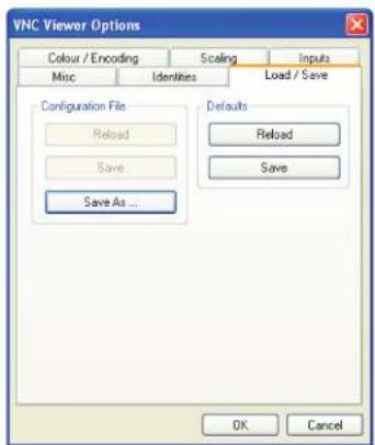
Defaults - Save
When clicked, saves the current connection options as the default set that will be used in all subsequent VNC connections.

Appendix 3 - VNC viewer window options
Click the VNC icon in the top left corner of the viewer window (or press F8) to display the window options:
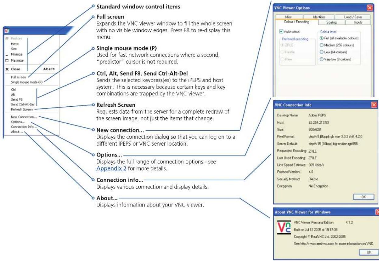

Appendix 4 - Browser viewer options
When you are connecting to the iPEPS using a Web browser, a number of options are available.

Click here to access the options
There are four options pages:
Encoding and colour level
Auto select
When ticked, this option will examine the speed of your connection to the iPEPS and apply the most suitable encoding method. This option is suggested for the majority of installations.
Preferred encoding
There are three manually selectable encoding methods which are accessible when the Auto select option is unticked.
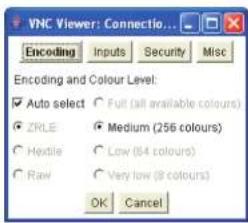
- ZRLE – This is a highly compressed method that is best suited to slow modem connections.
- Hextile – This method offers better performance than the ZRLE when used over a high speed network because there is no need for the iPEPS to spend time highly compressing the data.
- Raw – This is a primitive, uncompressed method that is mainly used for technical support issues. You are recommended not to use this method.
Colour level
The colour level is fixed at Medium (256 colours) for almost all browsers.
Inputs
View only (ignore mouse & keyboard)
When ticked, the viewer will not send keyboard or mouse information to the iPEPS or host system.
Accept clipboard from server
This feature is restricted to software server versions of VNC and has no effect on iPEPS installations.

Send clipboard to server
This feature is restricted to software server versions of VNC and has no effect on iPEPS installations.
Security
512 bits (low security)
Selects the lowest level of encoding for communications between the browser and the iPEPS.
1024 bits (medium security)
Selects the middle level of encoding for communications between the browser and the iPEPS.

2048 bits (high security)
Selects the highest level of encoding for communications between the browser and the iPEPS.
Misc
Shared (don't disconnect other viewers)
This feature is restricted to software server versions of VNC and has no effect on iPEPS installations.
Render cursor locally
This feature is restricted to software server versions of VNC and has no effect on iPEPS installations.
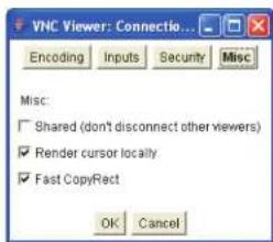
Fast CopyRect
This feature is restricted to software server versions of VNC and has no effect on iPEPS installations.

Appendix 5 - Remote configuration menus
This section covers the configuration menus that are available to remote admin users using either the VNC viewer or the browser methods of access.
To access the remote configuration menus
- Click the Configure button in the top right corner of the window when logged on as the admin user.


User accounts
This section allows you to manage up to sixteen separate accounts.
The first of the sixteen accounts is the admin account and is the only account with access rights to the configuration menus. The user name and access rights are fixed for the admin account, the only change possible for this account is the password.
There are fifteen user account positions.

To create a new account
1 Enter the required User Name to activate that position (the Password and access tick box positions will become editable).
2 Optionally enter a password for the user account.
3 Tick/untick the Local and/or Remote options that are appropriate to the user.
4 Click the Save button to register your changes.
To get here
1 Using VNC viewer or a browser, log on as the 'admin' user.
2 Click the 'Configure' button in the top right corner.
3 Click the 'User Accounts' option.
User Name
All user names must consist of lower case characters or numbers only. No symbols or upper case characters are permissible. The user name can be between 1 and 16 characters in length.
Password
Each password must be between 8 and 16 characters and contain at least 1 letter, 1 number and a special character. The password background remains amber whilst the password is considered too weak.
Local
When ticked, the selected user can gain access using the local KVM console directly connected to the iPEPS (dual access models only).
Remote
When ticked, the selected user can gain access via an IP network link, such as a local intranet or the wider Internet (depending on how the iPEPS is connected).

Unit configuration
This page provides access to a selection of both basic and fundamental settings for the iPEPS. Many of the settings displayed here are also accessible through the on-screen menu on the locally attached keyboard, mouse and monitor.

Hardware Version
Indicates the version of the electronic circuitry within the iPEPS unit.
Firmware Version
Indicates the version of the hardwired software within the iPEPS flash memory.
Host Keyboard Layout
Use the arrow buttons to match the keyboard layout expected by the host system.
Admin Password
Enter the password that will be used to gain administrator access to the iPEPS. There can only be one admin user and only that user is given access to the configuration menus.
To get here
1 Using VNC viewer or a browser, log on as the 'admin' user.
2 Click the 'Configure' button in the top right corner.
3 Click the 'Unit Configuration' option.
Unit Name
The name entered here will be displayed on the local menus and the remote VNC viewer/browser windows.
Local Hot Key Sequence
Use the arrow buttons to select an appropriate hot key sequence for the locally connected keyboard. This sequence is used in combination with other keypresses to access the on-screen menus. The options are: Ctrl+Alt (default), Ctrl+Shift, Alt+Shift, Alt Gr, Left + Right Alt, Left Ctrl + Alt or Right Ctrl + Alt.
Screensaver Timeout
Use the arrow keys to select an appropriate period of inactivity before a screensaver is displayed and the user is logged out. This setting applies to local users only and once the screensaver is displayed, for security purposes the user is required to log in again. The timeout period can be selected between 5 minutes and 1 day (24 hours) or you can choose the OFF setting to disable the screensaver feature.
Encryption
Three options are available: Always on, prefer off, prefer on. The one to choose depends on the specific details of your installation - see Encryption settings for details. The use of encryption imposes a slight performance overhead of roughly 10% but is highly secure against third party intrusion.
Advanced unit configuration
Click this button to display advanced options that do not normally require alteration.

Advanced unit configuration
Displays advanced options that do not normally require alteration.

To get here
1 Using VNC viewer or a browser, log on as the 'admin' user.
2 Click the 'Configure' button in the top right corner.
3 Click the 'Unit Configuration' option.
4 Click the 'Advanced Unit Configuration' option.
Force VNC Protocol 3.3
IMPORTANT: The use of this option is not recommended. Protocol 3.3 is a legacy version that does not offer any encryption.
Idle Timeout
Determines the period of inactivity on a remote connection before the user is logged out. The idle timeout period can be set to any time span, expressed in minutes. Note: The Screensaver option serves a similar purpose for local connections.
Protocol Timeout
Sets the time period by which responses should have been received to outgoing data packets. If the stated period is exceeded, then a connection is considered lost and terminated.
Background Refresh Rate
Use the arrow keys to alter the refresh rate for screen images via remote links. This allows you to tailor the screen refresh to suit the network speed. The options are: Slow, Medium, Fast or Disabled. When the disabled option is selected, the remote users will need to manually refresh the screen.
Note: When a low connection speed is detected, the background refresh is automatically disabled, regardless of the settings of this option.
Mouse Latency Allowance
This option is used during calibration to account for latency delays (caused as signals pass through a device) introduced by some KVM switches from alternative manufacturers.
During calibration, the iPEPS waits for 40ms after each mouse movement before sampling the next. If a KVM device adds a significant delay to the flow of data, the calibration process can be lengthened or may fail entirely. The value entered here is added to (or subtracted from) the default 40ms sampling time.
Note: You can enter negative values (down to -40) in order to speed up the calibration process when using fast KVM switches. Use this option with caution as it can adversely affect the calibration process.
Mouse Rate
Defines the rate at which mouse movement data are transmitted to the system. The default option is 20ms, which equates to 50 mouse events per second. This default rate can prove too fast when passed through certain connected KVM switches from alternative manufacturers. In such cases, data are discarded causing the local and remote mouse pointers to drift apart. If this effect is encountered, increase the mouse rate to around 30ms (data are then sent at a slower rate of 33 times per second).
Single Mouse Mode Mouse Switch
Allows you to select the mouse button combination that can be used to exit from single mouse mode (when active). Options are: Disabled, Middle+Right Button, Middle+Left Button.
Use Quick Mouse Calibration
Invokes optimised calibration techniques that handle the majority of mouse types.

Use Absolute Mouse by default
When selected, absolute mouse positioning data will be used rather than relative values.
Set cursor to arrow
Change remote cursor from a default dot to arrow shape.
Behaviour for admin connections when limit reached
Determines what should occur when four global connections already exist and a fifth, administrator connection attempt is made. Options are: Replace oldest connection, Replace newest connection and Don't replace. Only non-administrator connections can be terminated in this way.
Use VESA GTF
When ticked, the VESA Generalized Timing Formula will be used to help determine the correct input video resolution and timing details. See Appendix 9 for a list of all supported video modes.
Enable Virtual Media
When checked, allows file transfers to occur. See page 32.
Upgrade firmware
Places the unit into upgrade mode.
Reset Unit
Performs a complete cold boot of the iPEPS unit.

Time & date configuration
This page allows you to configure all aspects relating to time and date within the iPEPS.
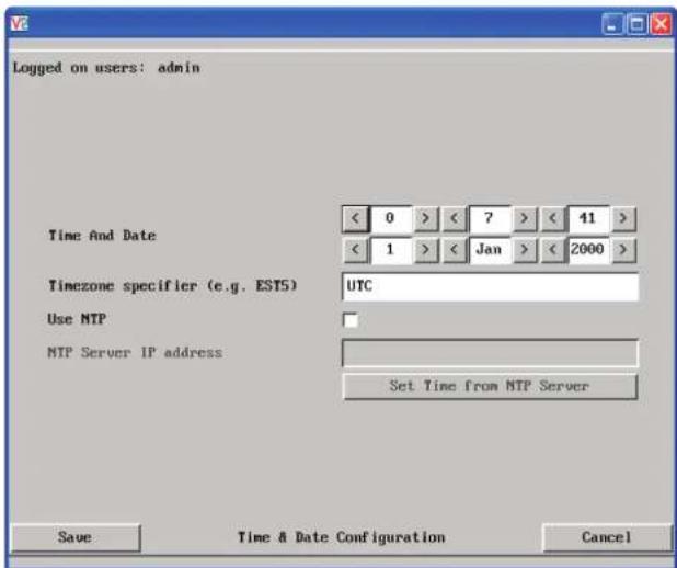
Time and Date
Use the arrow buttons to set the correct current time.
Use NTP
When this option is selected, the iPEPS will synchronise its internal clocks using information from the (Network Time Protocol) server listed in the NTP Server IP address field.
NTP Server IP address
Optionally enter the IP address for a known Network Time Protocol server.
Set Time from NTP Server
Click to immediately use the time and date information from the listed NTP server.
Timezone specifier
Optionally enter a recognised timezone specifier related to the current position of the iPEPS. When an NTP server is used, the specifier will be used to provide the correct real time.
The timezone specifier takes the following form:
std offset dst [offset], start[/time], end[/time]
The std and offset specify the standard time zone, such as GMT and 0, or CET and -1, or EST and 5, respectively.
The dst string and [offset] specify the name and offset for the corresponding Daylight Saving Time zone; if the offset is omitted, it defaults to one hour ahead of standard time.
The remainder of the specification describes when Daylight Saving Time is in effect. The start field is when Daylight Saving Time goes into effect and the end field is when the change is made back to standard time. The most common format used for the daylight saving time is: mm.w.d
Where: m specifies the month and must be between 1 and 12. The day d must be between 0 (Sunday) and 6. The week w must be between 1 and 5; week 1 is the first week in which day d occurs, and week 5 specifies the last d day in the month.
The time fields specify when, in the local time currently in effect, the change to the other time occurs. If omitted, the default is 02:00:00.
Typical examples are:
UK: GMT0BST,M3.5.0/1,M10.5.0/2
Central Europe: CET-1CEST,M3.5.0/2,M10.5.0/3
US Eastern (2006): EST5EDT,M4.1.0/2,M10.5.0/2
US Pacific (2006): PST8PDT,M4.1.0/2,M10.5.0/2
US Eastern (from 2007): EST5EDT,M3.2.0/2,M11.1.0/2
US Pacific (from 2007): PST5PDT,M3.2.0/2,M11.1.0/2
For further details
- For details of timezone specifier formats, please refer to: http://www.gnu.org/software/libc/manual/html_node/TZ-Variable.html
- For details of the Network Time Protocol (main RFC number: 1305; the SNTP subset used as the basis for the iPEPS: 4330) http://www.ietf.org/rfc.html
To get here
1 Using VNC viewer or a browser, log on as the 'admin' user.
2 Click the 'Configure' button in the top right corner.
3 Click the 'Time & Date Configuration' option.

Network configuration
This page allows you to configure the various aspects of the IP port and its relationship with the local network.

MAC address
Media Access Control address – this is the unique and unchangeable code that was hard coded within your iPEPS unit when it was built. It consists of six 2-digit hexadecimal (base 16) numbers separated by colons. A section of the MAC address identifies Adder Technology as the manufacturer, while the remainder is effectively the unique electronic serial number of your particular unit.
Use DHCP
DHCP is an acronym for 'Dynamic Host Configuration Protocol'. Its function is particularly useful when connecting to medium size or larger networks. When this option is selected, your iPEPS will attempt to locate a DHCP server on the network. If such a server is located, it will supply three things to the iPEPS: an IP address, an IP network mask (also known as a Subnet mask) and a Gateway address. These are not usually granted permanently, but on a 'lease' basis for a fixed amount of time or for as long as the iPEPS remains connected and switched on. Discover allocations.
To get here
1 Using VNC viewer or a browser, log on as the 'admin' user.
2 Click the 'Configure' button in the top right corner.
3 Click the 'Network Configuration' option.
IP Address
This is the identity of the iPEPS within a network. The IP address can be thought of as the telephone number of the iPEPS. Unlike the MAC address, the IP address can be altered to suit the network to which it is connected. It can either be entered manually or configured automatically using the DHCP option. When the DHCP option is enabled, this entry is greyed out.
IP Network Mask
Also often called the subnet-mask, this value is used alongside the IP address to help define a smaller collection (or subnet) of devices on a network. In this way a distinction is made between locally connected devices and ones that are reachable elsewhere, such as on the wider Internet. This process helps to reduce overall traffic on the network and hence speed up connections in general.
IP Gateway
This is the address of the device that links the local network (to which the iPEPS is connected) to another network such as the wider Internet. Usually the actual gateway is a network switch or router and it will be used whenever a required address lies outside the current network.
VNC Port
This is the logical link through which communications with a remote VNC viewer will be channelled (see What is a port?). The default setting is 5900 which is a widely recognised port number for use by VNC software. However, in certain circumstances it may be advantageous to alter this number - see 'Security issues with ports' for more details.
HTTP Port
This is the logical link through which communications with a remote web browser will be channelled (see What is a port?). The default setting of 80 is an established standard for web (HTTP - HyperText Transfer Protocol) traffic though this can be changed to suit your local network requirements.
IP Access Control
This section allows you to optionally specify ranges of addresses which will or won't be granted access to the iPEPS. If this option is left unchanged, then the default entry of '+0.0.0.0/0.0.0.0' ensures that access from all IP addresses will be permitted. See Setting IP access control for details.

Setting IP access control
The golden rule with this feature is 'Include before you exclude' or to put it another way 'Arrange allowed addresses in the list before the denied addresses'.
This is because the positions of entries in the list are vitally important. Once a range of addresses is denied access, it is not possible to make exceptions for particular addresses within that range. For instance, if the range of addresses from A to F are denied access first, then the address C could not be granted access lower down the list. Address C needs to be placed in the list before the denied range.
IMPORTANT: This feature should be configured with extreme caution as it is possible to deny access to everyone. If such an error occurs, see Clear IP access control for details about how to regain access.

In the list, access control addresses prefixed by '+' are allow entries while those prefixed by '-' are deny entries.
To get here
1 Using VNC viewer or a browser, log on as the 'admin' user.
2 Click the 'Configure' button in the top right corner.
3 Click the 'Network Configuration' option.
To define a new IP access control entry
1 Click the Add button to display a popup dialog:
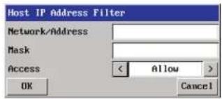
Network/Address
Enter the network address that is to be allowed or denied access. If a range of addresses is being specified then specify any one of the addresses within the range and use the Mask entry to indicate the size of the range.
Mask
Enter an IP network mask that indicates the range of addresses that are to be allowed or denied access. For instance, if only a single specified IP address were to be required, the mask entry would be 255.255.255.255 in order to specify a single location. See Calculating the mask for IP access control for details.
Access
Use the arrow buttons to select either 'Allow' or 'Deny' as appropriate.
2 Enter the base network address, the mask and select the appropriate access setting.
3 Click the OK button.
To reorder access control entries
IMPORTANT: When reordering, ensure that any specific allowed addresses are listed higher in the list than any denied addresses. Take care not to invoke any deny access settings that would exclude valid users.
1 In the access control list, click on the entry to be moved.
2 Click the Up or Down buttons as appropriate.
To edit/remove access control entries
1 In the access control list, click on the appropriate entry.
2 Click either the Edit or Remove button as appropriate.

Hotkey sequences
iPEPS allows you to enter commands that take the form of hotkey sequences that emulate standard keypress combinations.
Hotkey sequences
Almost any combination of keypresses can be emulated using the following notations:
- means press down the key that follows,
- means release the key that follows,
+- means press and then release the key that follows,
* means add a delay. The standard delay period is 250ms, however, if a number immediately follows the asterisk, this will define an alternate delay period (in milliseconds).
A list of permissible keypresses and information about how to abbreviate them are given in Appendix 8.
Notes
• The entries are not case sensitive.
- It is not necessary to specify all keys to be released at the end because they are all released automatically after the last code.
Examples
To send the command Ctrl + Alt 4 you should use the following: +Ctrl+Alt+4. To send the command Ctrl + Alt 12 you should use the following: +Ctrl+ALT+1+2 (the '+-1' entry causes the 1 key to be pressed and released before the 2 key is pressed).
To send the command Scroll lock 1 + Enter (with a 500ms delay) you should use the following: +-Scr*500+1+Ent

Logging and status
This screen provides various details about the user activity on the iPEPS.
Note: The log has a maximum capacity of 1000 event lines. After 1000 entries, the oldest entries are overwritten. If log data are important to your installation, ensure a regular backup procedure or use the Syslog Server IP Address option to send log information automatically to another system.

To copy and paste the log
You can copy the information listed within the log and paste it into another application.
1 While viewing the log screen, press Ctrl and C, to copy the data into the clipboard.
2 In a text application (i.e. Word, WordPad, Notepad) press Ctrl and V, or right mouse click and 'Paste'.
Syslog Server IP Address
Logging information can optionally be sent, as it occurs, to a separate system using the standard Syslog protocol. Enter the IP address of a suitable system in the field provided.
For further details
- For details of the Syslog protocol (RFC number: 3164) http://www.ietf.org/rfc.html
To get here
1 Using VNC viewer or a browser, log on as the 'admin' user.
2 Click the 'Configure' button in the top right corner.
3 Click the 'Logging and Status' option.

Appendix 6 – Addresses, masks and ports
IP address, network masks and ports are all closely linked in the quest for one device to find another across disparate network links.
IP addresses
As a rough analogy, consider how you use the telephone system. The phone number for Adder Technology in the UK is 0044 (0)1954 780044. This number consists of three distinct parts:
• 0044 connects from another country to the UK
• (0)1954 selects the main telephone exchange in the Bar Hill area of Cambridgeshire, and
• 780044 is the unique code for Adder Technology within Bar Hill.
The important parts of the whole number depend on where you are. If you were based in the same local area as Adder Technology, there would be no point in dialling out of the UK, or even out of the area. The only part of the whole number that you are interested in is the final part: 780044.
In a similar way to the various parts of the telephone number, the four sections (or Octets) of every IP address have different meanings or "weights". Consider the following typical IP address:
192.168.142.154
192 is the most global part of the number (akin to the 0044 of the phone number) and 154 is the most local (similar to the 780044 unique local code of the phone number).
When two network devices communicate with each other, they always "dial the whole number" regardless of their respective locations in a network. However, they still need to know whether the other device is local to them or not, and this is where the net mask comes into play.
Net masks
The net mask (or sub-net mask) informs a device as to its own position within a network. From this it can determine whether any other device is within the same local network or is situated further afield.
Taking the telephone number analogy given in the IP address section, in order to use the telephone system efficiently, it is vital for you to know your location relative to the person you are calling. In this way you avoid dialling unnecessary numbers.
When one network device needs to talk to another, the first thing that it will do is a quick calculation using its own IP address, the other device's IP address and its own net mask. Suppose a device with address 192.168.142.154 and net mask 255.255.255.0 needed to communicate with a device at address 192.168.142.22. The sending device would perform several calculations:

flowchart
graph TD
    A["192.168.142.154"] --> B["255.255 255.0"]
    B --> C["192.168.142.000"]
    C --> D["Result"]
    E["192.168.142.22"] --> F["255.255 255.0"]
    F --> G["192.168.142.000"]
    G --> H["Address is local"]
    I["Destination device IP address"] --> J["255.255 255.0"]
    J --> K["192.168.142.000"]
    L["Answer: YES"] --> M["4"]
1 The net mask is used to determine the local and global parts of the sender's IP address. Where there is 255 in the mask, the corresponding address slips through, where there is a 0, it is blocked.
2 Where the net mask was 0, the corresponding part of the result is also zero - this section is now known to be the local part of the IP address.
3 The same process is carried out for the destination address, again using the sender's net mask. Now the local parts of both addresses have been equalised to zero, because their values are not important in determining whether they are both in the same local network.
4 The results of the two net mask operations are now compared, if they match, the destination is local. If not, then the sender will still use the same full destination IP address but will also flag the message to go via the local network gateway and out into the wider world.
The reason for doing this? It makes the network, as a whole, much more efficient. If every message for every recipient was shoved straight out onto the Internet, the whole thing would grind to a halt within seconds. Net masks keep local traffic just that - local.
Want to know more?

Net masks - the binary explanation
To really understand the operation of a net mask it is necessary to delve deeper into the life blood of computers – binary; this is native digital, where everything is either a 1 (one) or 0 (zero), on or off, yes or no.
The net mask operation described on the previous page is known as a 'bit-wise AND function'. The example of 255.255.255.0 is handy because the last octet is completely zero and is "clean" for illustrative purposes. However, actual net mask calculations are carried out, not on whole decimal numbers, but bit by bit on binary numbers, hence the term 'bit-wise'. In a real local network, a net mask might be 255.255.255.240. Such an example would no longer be quite so clear, until you look at the net mask in its binary form:
11111111.11111111.11111111.11110000
In this case, the four zeroes at the end of the net mask indicate that the local part of the address is formed by only the last four bits. If you use the diagram from the previous example and insert the new net mask, it will have the following effect on the final result:

Thus, when 154 is bit-wise ANDed with 240, the result is 144. Likewise, any local address from 192.168.142.144 through to 192.168.142.159 would produce exactly the same result when combined with this net mask, hence they would all be local addresses. However, any difference in the upper three octets or the upper four bits of the last octet would slip through the mask and the address would be flagged as not being local.

Calculating the mask for IP access control
The IP access control function uses a standard IP address and a net mask notation to specify both single locations and ranges of addresses. In order to use this function correctly, you need to calculate the mask so that it accurately encompasses the required address(es).
Single locations
Some of the simplest addresses to allow or deny are single locations. In this case you enter the required IP address into the 'Network/Address' field and simply enter the 'Mask' as 255.255.255.255 (255 used throughout the mask means that every bit of the address will be compared and so there can only be one unique address to match the one stated in the 'Network/Address' field).
All locations
The other easy setting to make is ALL addresses, using the mask 0.0.0.0 As standard, the IP access control section includes the entry: +0.0.0.0/0.0.0.0 The purpose of this entry is to include all IP addresses. It is possible to similarly exclude all addresses, however, take great care not to do this as you instantly render all network access void. There is a recovery procedure should this occur.
Address ranges
Although you can define ranges of addresses, due to the way that the mask operates, there are certain restrictions on the particular ranges that can be set. For any given address you can encompass neighbouring addresses in blocks of either 2, 4, 8, 16, 32, 64, 128, etc. and these must fall on particular boundaries. For instance, if you wanted to define the local address range:
192.168.142.67 to 192.168.142.93
The closest single block to cover the range would be the 32 addresses from: 192.168.142.64 to 192.168.142.95.
The mask needed to accomplish this would be: 255.255.255.224
When you look at the mask in binary, the picture becomes a little clearer. The above mask has the form: 11111111.11111111.11111111.1100000 Ignoring the initial three octets, the final six zeroes of the mask would ensure that the 32 addresses from .64 (01000000) to .95 (01011111) would all be treated in the same manner. See Net masks - the binary explanation for details.
When defining a mask, the important rule to remember is:
There must be no 'ones' to the right of a 'zero'.
For instance, (ignoring the first three octets) you could not use a mask that had 11100110 because this would affect intermittent addresses within a range in an impractical manner. The same rule applies across the octets. For example, if you have zeroes in the third octet, then all of the fourth octet must be zeroes.
The permissible mask values (for all octets) are as follows:
Mask octet Binary Number of addresses encompassed
| 255 | 11111111 | 1 address |
| 254 | 11111110 | 2 addresses |
| 252 | 11111100 | 4 addresses |
| 248 | 11111000 | 8 addresses |
| 240 | 11110000 | 16 addresses |
| 224 | 11100000 | 32 addresses |
| 192 | 11000000 | 64 addresses |
| 128 | 10000000 | 128 addresses |
| 0 | 00000000 | 256 addresses |
If the access control range that you need to define is not possible using one address and one mask, then you could break it down into two or more entries. Each of these entries could then use smaller ranges (of differing sizes) that, when combined with the other entries, cover the range that you require. For instance, to accurately encompass the range in the earlier example: 192.168.142.67 to 192.168.142.93
You would need to define the following six address and mask combinations in the IP access control section:
Network/address entry Mask entry
| 192.168.142.67 | 255.255.255.255 | defines 1 address (.67) |
| 192.168.142.68 | 255.255.255.252 | defines 4 addresses (.68 to .7 |
| 192.168.142.72 | 255.255.255.248 | defines 8 addresses (.72 to .7 |
| 192.168.142.80 | 255.255.255.248 | defines 8 addresses (.80 to .8 |
| 192.168.142.88 | 255.255.255.252 | defines 4 addresses (.88 to .9 |
| 192.168.142.93 | 255.255.255.255 | defines 1 address (.93) |

Ports
If you accept the analogy of IP addresses being rather like telephone numbers, then think of ports as extension numbers. In a company of any size, you generally wouldn't expect the accounts department to share the same telephone with the technical department. Although their calls may all be related to the same company, they concern very different aspects of that company.
It is the same with IP network connections. Although you have only one network link into your computer and only one IP address (phone number), you are probably performing many different tasks through that one link, often at the same time. Thus, when you browse the web your outgoing requests and the incoming information are all channelled through port 80. When you send an email, it travels through port 25 and when you transfer files you are, without knowing it, using port 20.
At the "border crossing" between the wider Internet and every local network attached to it, there is a router that is usually combined with a firewall. One of its main tasks is to direct incoming traffic to the correct place within its local network. A key piece of information to help it do this is the port number:

flowchart
graph TD
    A["User accesses the company website at: 129.7.1.10 (this automatically uses port 80)."] --> B["Internet"]
    C["User with VNC viewer accesses IP address: 129.7.1.10 (this automatically uses port 5900)."] --> B
    D["Router/firewall address: 129.7.1.10\nRouter is programmed to send port 5900 VNC traffic to local address 192.168.0.3 and port 80 web traffic to local address 192.168.0.42"] --> E["Web server"]
    F["ADDR/FANK /PHP ADDER"] --> E
IPEPS has the local IP address: 192.168.0.3
Web server has the local IP address: 192.168.0.42
Security issues with ports
The settings of port numbers become important when the iPEPS is situated behind a network firewall. In order for a remote VNC viewer or web browser to make contact with your iPEPS, it is necessary for the firewall to allow communication through a particular numbered port to occur.
One specific function of firewalls is to restrict access to ports in order to prevent malicious attackers using them as a route into your network. Every new port that is opened offers a new possibility for hackers and so the number of accessible ports is purposefully kept to a minimum. In such cases, it may be advantageous to change one or both iPEPS ports to use the same number. The other alternative is to place the iPEPS unit outside the firewall and take full advantage of its secure operation features – see Networking issues for details. IMPORTANT: The correct configuration of routers and firewalls requires advanced networking skills and intimate knowledge of the particular network. Adder Technology cannot provide specific advice on how to configure your network devices and strongly recommend that such tasks are carried out by a qualified professional.

Appendix 7 – Cable and connector specifications
RS232 serial mouse to PS/2 converter cable
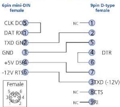
flowchart
graph TD
    A["6pin mini-DIN female"] --> B["CLK DC⑤"]
    A --> C["DAT RX①"]
    A --> D["TXD GN②"]
    A --> E["GND ③"]
    A --> F["+5V DSR④"]
    A --> G["-12V RTS⑥"]
    H["9pin D-type female"] --> I["NC ①"]
    H --> J["②"]
    H --> K["⑤"]
    H --> L["④"]
    H --> M["⑥"]
    H --> N["⑦"]
    H --> O["③TXD (-12V)"]
    P["Female"] --> Q["5 6 3 4 2"]

Appendix 8 – Hotkey sequence codes
These codes are used when defining hotkey switching sequences (macros) for the host computer and allow you to include almost any of the special keys on the keyboard.
Permissible key presses
Main control keys (see 'Using abbreviations')
Backspace | Tab | Return | Enter | Ctrl | Alt | Win | Shift | LShift | RShift
LCtrl | RCtrl | LAlt | AltGr | RAlt | LWin | RWin | Menu | Escape | Space
CapsLock | NumLock | PrintScreen | Scrolllock
Math operand keys (see 'Using abbreviations')
Add (Plus) | Subtract (Minus) | Multiply
Central control keys (see 'Using abbreviations')
Insert | Delete | Home | End | PageUp | PageDown
Up | Down | Left | Right | Print | Pause
Keypad keys (see 'Using abbreviations')
KP_Insert | KP_Delete | KP_Home | KP_End | KP_PageUp
KP_PageDown | KP_Up | KP_Down | KP_Left | KP_Right | KP_Enter
KP_Add | KP_Subtract | KP_Divide | KP_Multiply
KP_0 to KP_9
Function keys
F1 | F2 | F3 | F4 | F5 | F6 | F7 | F8 | F9 | F10 | F11 | F12
ASCII characters
All characters can be entered using their ASCII codes, from 32 to 126 (i.e. A,B,C,
... 1,2,3 etc.) with the exception of the special characters '+', '-', '+-' and '*'
which have special meanings, as explained below.
Codes with special meanings
+ means press down the key that follows,
– means release the key that follows,
+ means press down and release the key that follows,
* means wait 250ms (note: if a number immediately follows the asterisk, then the delay will equal the number, in milliseconds).
Note: Hotkey sequences are not case sensitive.
Creating macro sequences
Hot key macro sequences can be up to 256 characters long. All keys are assumed to be released at the end of a line, however, you can also determine that a key is pressed and released within a sequence. Any of the following three examples will send a command that emulates and a press and release of the Scroll Lock key:
+SCROLL-SCROLL
+-SCROLL
+SCROLL-
Example:
+-SCROLL+-SCROLL+1+ENTER
Press and release scroll twice, press 1 then enter then release all keys (equivalent definition is +SCROLL-SCROLL+SCROLL-SCROLL+1+ENTER-1-ENTER)
Using abbreviations
To reduce the length of the key definitions, any unique abbreviation for a key can be used. For example: "scroll", "scr" and even "sc" all provide an identifiable match for "ScrollLock" whereas "en" could not be used because it might mean "Enter" or "End" ("ent" would be suitable for "Enter").
Note: Hotkey sequences and abbreviations are not case sensitive.
For information about where to enter these codes, please see the sections Host configuration or Keyboard control.

Appendix 9 – Supported video modes
The following video modes are supported and can be automatically configured by the iPEPS. If a recognised video mode cannot be found, the iPEPS will gradually change some of the key parameters to discover whether a video lock can be achieved. Support for VESA GTF (Generalized Timing Formula) is available and can be enabled via the Advanced Unit Configuration screen.
The half width video modes capture every other pixel. These are not generally recommended for normal use but may be used for emergency access to high resolution, high frequency system screens. Half width screens can be expanded to normal width using the scaling features of the viewer.
| vesa 720 x 400 @ 85Hz | sun 1152 x 900 @ 66Hz |
| vesa 640 x 480 @ 60Hz | sun 1152 x 900 @ 76Hz |
| vesa 640 x 480 @ 72Hz | sun 1280 x 1024 @ 67Hz |
| vesa 640 x 480 @ 75Hz | apple 640 x 480 @ 67Hz |
| vesa 640 x 480 @ 85Hz | apple 832 x 624 @ 75Hz |
| vesa 800 x 600 @ 56Hz | apple 1152 x 870 @ 75Hz |
| vesa 800 x 600 @ 60Hz | 1900 x 1200 @ 60Hz** |
| vesa 800 x 600 @ 73Hz |
vesa 800 x 600 @ 75Hz
vesa 800 x 600 @ 85Hz
vesa 1024 x 768 @ 60Hz
vesa 1024 x 768 @ 70Hz
vesa 1024 x 768 @ 75Hz
vesa 1024 x 768 @ 85Hz
vesa 1152 x 864 @ 75Hz
vesa 1280 x 960 @ 60Hz
vesa 1280 x 1024 @ 60Hz
vesa 1280 x 1024 @ 75Hz
vesa 1600 x 1200 @ 60Hz
vesa 1600 x 1200 @ 65Hz half-width
vesa 1600 x 1200 @ 70Hz half-width
vesa 1600 x 1200 @ 75Hz half-width
vesa 1600 x 1200 @ 85Hz half-width
vesa 720 x 400 @ 70Hz*
* Not actually a VESA mode but a common DOS/BIOS mode
** May also work on some systems when the operating temperature of the iPEPS is controlled.
General Public License (Linux)
The iPEPS runs an embedded version of the Linux operating system, licensed under the GNU General Public License. To obtain the source code for the open-source components of the system visit:
http://www.realvnc.com/products/iPEPSIP/gpl.html.

End user licence agreement
PLEASE READ THIS AGREEMENT CAREFULLY. THIS AGREEMENT CONCERNS ENHANCED VNC VIEWER SOFTWARE ("the SOFTWARE") FOR USE WITH THE iPEPS PRODUCT ("the PRODUCT"). THE SOFTWARE IS PROVIDED TO ENABLE YOU TO OPERATE THE PRODUCT. BY USING ALL OR ANY PORTION OF THE SOFTWARE YOU ACCEPT ALL THE TERMS AND CONDITIONS OF THIS AGREEMENT. IF YOU DO NOT ACCEPT ALL THE TERMS AND CONDITIONS OF THIS AGREEMENT THEN DO NOT USE THE SOFTWARE. BY USING ANY UPDATED VERSION OF THE SOFTWARE WHICH MAY BE MADE AVAILABLE, YOU ACCEPT THAT THE TERMS OF THIS AGREEMENT APPLY TO SUCH UPDATED SOFTWARE.
1. Intellectual Property Rights
The Software and its structure and algorithms are protected by copyright and other intellectual property laws, and all intellectual property rights in them belong to RealVNC Limited ("RealVNC"), a United Kingdom Limited Company, or are licensed to it. You may not reproduce, publish, transmit, modify, create derivative works from, publicly display the Software or part thereof. Copying or storing or using the Software other than as permitted in Clause 2 is expressly prohibited unless you obtain prior written permission from RealVNC.
2. Permitted and Prohibited Uses
2.1 During the term of this Agreement and as long as you comply with the terms of this agreement, you may use the Software only with the Product for your personal use or for the internal use of your business. You may make as many copies of the Software as you require for your own internal business purposes only and for archival purposes. You are expressly prohibited from distributing the Software in any format, in whole or in part, for sale, or for commercial use or for any unlawful purpose.
2.2 You may not rent, lease or otherwise transfer the Software or allow it to be copied. Unless permitted by law, you may not reverse engineer, decompile or disassemble the Software.
3. Warranty
REALVNC DOES NOT WARRANT ANY RESULTS OBTAINED USING THE SOFTWARE. TO THE EXTENT PERMITTED BY LAW, REALVNC DISCLAIMS ALL OTHER WARRANTIES ON THE SOFTWARE, EITHER EXPRESS OR IMPLIED, INCLUDING BUT NOT LIMITED TO THE IMPLIED WARRANTIES OF MERCHANTABILITY, NON-INFRINGEMENT OF THIRD PARTY RIGHTS AND FITNESS FOR PARTICULAR PURPOSE.
4. Limitation on Liability
UNDER NO CIRCUMSTANCES SHALL REALVNC BE LIABLE FOR ANY CONSEQUENTIAL INDIRECT OR INCIDENTAL DAMAGES WHATSOEVER INCLUDING LOST PROFITS OR SAVINGS ARISING OUT OF THE USE OF THE SOFTWARE, THE SERVICE OR THE INFORMATION, RELIANCE ON THE DATA PRODUCED OR INABILITY TO USE THE SOFTWARE, THE SERVICE OR THE INFORMATION EVEN IF REALVNC HAS BEEN ADVISED OF THE POSSIBILITY OF SUCH DAMAGES. BECAUSE SOME STATES AND COUNTRIES DO NOT ALLOW THE EXCLUSION OR LIMITATION OF LIABILITY FOR CONSEQUENTIAL OR INCIDENTAL DAMAGES, THE ABOVE LIMITATION MAY NOT APPLY TO YOU. NOTHING IN THIS AGREEMENT LIMITS LIABILITY FOR DEATH OR PERSONAL INJURY ARISING FROM A PARTY'S NEGLIGENCE OR FROM FRAUDULENT MISREPRESENTATION ON THE PART OF A PARTY
5. Export Control
The United States and other countries control the export of Software and information. You are responsible for compliance with the laws of your local jurisdiction regarding the import, export or re-export of the Software, and agree to comply with such restrictions and not to export or re-export the Software where this is prohibited. By downloading the Software, you are agreeing that you are not a person or entity to which such export is prohibited.
6. Term and Termination
This licence shall continue in force unless and until it is terminated by RealVNC by e-mail notice to you, if it reasonably believes that you have breached a material term of this Agreement
In the case above, you must delete and destroy all copies of the Software in your possession and control and overwrite any electronic memory or storage locations containing the Software.
7. General Terms
7.1 The construction, validity and performance of this Agreement shall be governed in all respects by English law, and the Parties agree to submit to the exclusive jurisdiction of the English courts.
7.2 If any provision of this agreement is found to be invalid by any court having competent jurisdiction, the invalidity of such provision shall not affect the validity of the remaining provisions of this agreement, which shall remain in full force and effect.
7.3 No waiver of any term of this agreement shall be deemed a further or continuing waiver of such term or any other term.
7.4 This agreement constitutes the entire agreement between you and RealVNC.


www.adder.com
Documentation by:

www.ctxd.com
© 2020 Adder Technology Limited
All trademarks are acknowledged.
Part No. MAN-AL-IPEPS • Release 1.3

Index

A
Access control
configuration 54
mask calculation 59
Access mode
shared & private 27
Account
creation for users 48
Address
explanation 57
Addressing
DNS 20
network issues 20
Admin password
initial setup 12
local setting 37
Advanced unit configuration
50
Artifacts
on screen 26
Assistance
from Adder 35
Auto calibrate 28
Auto select 41,46
B
Binary
net masks 58
Browser
connection 25
C
Cables 5
Cable specifications
57,61,62,63
Calibrate
mouse 27
screen 28
Calibrate all
video settings 30
Clear IP access control
local setting 38
Colour level 41
Configuration
initial steps 11
remote 18
Connections
host computer 7
keyboard 8
local 22
modem 9
monitor 8
mouse 8
network port 8
remote 23
Connector specifications 61
Control menus
for local connection 36
for remote connection 26,47
Controls
viewer options 28
D
Date
local setting 37
DHCP
discovering allocations 20
during initial setup 12
local setting 38
remote setting 53
DNS addressing 20
E
Encryption key 12
Encryption settings 13
viewer 34
End user licence 64
F
Firewall 19
Firmware
current version 49
Force encryption 37
Full screen mode
escape from (F8) 26
G
Gateway
local setting 38
remote setting 53
H
Hextile 41,46
Host computer
connecting 7
Host configuration 55
Hosts
configuration 55
Hotkeys
to access menus 36
Hotkey sequences 55
codes and macros 62
HTTP port
initial setup 12
local setting 38
remote setting 53
when altered 19
1
Identities
VNC Viewer 44
Indicators 4
Initial configuration 11
IntelliMouse 14
IP access control 53,54
calculating mask 59
IP address
explanation 57
local setting 38
remote setting 53
IP gateway 53
IP network mask 53
IP network port 4
connecting 8
K
Keyboard codes
sending 29
Keyboard Layout
remote setting 49
Keyboard layout
local setting 37
KVM console 4
L
Local connection 22
local control menus 36
Local network
connection 19
Logging 56
Log on 16,24
M
MAC address 38,52,53
Mask
explanation 57
for IP access control 59
Menu bar
viewer window 26
Menu key
changing 42
Menus
local 36
remote 47
Modern
connecting 9
Modem configuration 39
Mouse
calibration 28
control 29
pointers 27
restoration 13,14
resync 27,28
N
Net mask 38
explanation 57
Network configuration 38,53
Networking issues 19
Network port
connecting 8
Network settings
resetting back to default 17
0
Octets
ip address 57
P
Password
admin - setting 37
initial setup 12
remote logon 16,24
setting for users 48
Port number
entering 33
Power switching
configuration 22
on & off select 28
Preferred encoding 41
Private
access mode 27
R
Raw 41,46
Refresh screen 28
Remote configuration 18
advanced unit configuration
50
host configuration 55
logging and status 56
main menu 47
network configuration 53
setting IP access control 54
unit configuration 49
user accounts 48
Remote connection 23
Reset configuration 39
Resync mouse 28
Router 19
S
Scaling
VNC Viewer 43
Screen
best resolution 26
calibration 28
navigation 26
refresh 28
Screensaver
local setting 37
remote setting 49
Security
ensuring 21
Server
configuration 55
Setup procedure
local setup 11,12,16
remote setup 18
Shared
access mode 27
Single mouse mode 27,28
Slow connections
optimising for 26
Supplied items 5
Syslog 56
T
Threshold
adjustment 30
Time
local setting 37
remote setting 49
Troubleshooting 35
U
Unit configuration 37,49
Unit name
local setting 37
remote setting 49
USB converter 5
Use DHCP
local setting 38
User accounts 48
Username
initial setup 12
remote logon 16,24
V
Video modes 63
Video settings 31
Viewer window 26
Virtual Media 3
operation 31,32
VNC port
initial setup 12
local setting 38
remote setting 53
when altered 19
VNC viewer
configuration menus 47
connection 24
connection options 41
download 33
window options 45
W
Web browser
connection 25
viewer options 46
Z
ZRLE 41,46

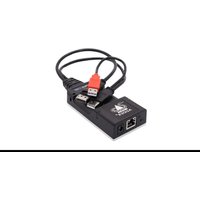
- Installation
- Configuration
- Operation
- Further information
- Index
- Introduction
- Adder Virtual Media feature
- USB adapters
- AdderLink iPEPS features
- KVM console
- Connections to computer
- Non Dual Access model
- IP network port
- Indicators
- Switches
- Mounting
- Connections
- Host computer
- To attach the KVM cable to the iPEPS
- To attach the KVM cable to the computer
- Local keyboard, video monitor and mouse
- Note: Dual Access model only
- To connect a local keyboard, video monitor and mouse
- To connect the IP network port
- Power supply connection
- Power supply issues and options
- To connect the optional power adapter
- To use a common power adapter to supply multiple iPEPS units
- Initial configuration
- Part 1 – Initial configuration
- Part 1 - Initial configuration (Dual Access model)
- Part 2 - Remote configuration
- Part 1 – Initial configuration (Standard or Dual Access models)
- Controlling the local configuration menus
- To perform the initial local configuration (Dual Access model only)
- Admin password
- Time and Date
- Encryption
- Use DHCP/IP address/Net Mask/Gateway
- VNC and HTTP ports
- Logoff
- Restore mouse functions
- Return to host
- Encryption settings
- iPEPS encryption settings
- Viewer encryption settings
- Hot plugging and mouse restoration
- Which restore setting do I use?
- Recognising an IntelliMouse-style mouse
- Recognising an IntelliMouse driver
- To restore mouse operation when hot plugging:
- Resetting the configuration (Dual Access models only)
- The iPEPS does not display the configuration sequence
- To invoke a configuration reset by main menu
- To perform the initial local configuration
- If the iPEPS does not respond on the network
- To reset the iPEPS to its default network settings
- To alter the iPEPS network settings via USB connection
- Unit configuration
- Time & Date Configuration
- Network configuration
- Logging and status
- To perform the remote configuration
- Networking issues
- Positioning iPEPS in the network
- Placing iPEPS behind a router or firewall
- Port settings
- When a web server is also on the local network
- http://192.168.47.10:8000
- If you need to change the VNC port number
- 192.168.47.10::11590
- Addressing
- To discover a DHCP-allocated IP address
- DNS addressing
- Placing iPEPS alongside the firewall
- Ensuring sufficient security
- Ports
- Connecting to the iPEPS
- Local connection (dual access models only)
- To make a local connection:
- To view the local control menu
- Local connection (continued)
- To avoid the 'hall of mirrors' effect
- Remote connections
- Remote connection by VNC viewer
- To connect using the VNC viewer
- v.w.x.y
- Remote connection by Web browser
- To connect using your Web browser
- http://v.w.x.y
- Options button
- Using the viewer window
- The menu bar
- When using the viewer window
- What is the best screen resolution to use?
- How do I navigate around a larger screen?
- How do I escape from full screen mode?
- Why is the + button flashing red?
- How do I remove traces of moved items from the screen?
- How do I make the most of a slow connection?
- Adjust the Threshold setting
- Fewer colours
- Rate limit mouse events
- Mouse pointers
- Re-synchronise mouse
- To re-synchronise the mouse
- Access mode - shared/private
- To change the access mode
- Auto calibrate
- To auto calibrate the screen and/or mouse
- Controls
- Single Mouse Mode
- Resync Mouse
- Refresh Screen
- Mouse Control
- Keyboard Control
- When entering codes:
- Video Settings
- Phase
- Horizontal position
- Vertical position
- Colour, brightness &
- Calibrate all
- Display activity
- Using automatic configurations
- Setting the Threshold manually
- Advanced Settings
- Pixel Format
- Motion Detection
- Overlap Capture
- Tile Width and Height
- Virtual Media
- Info
- To remotely transfer files to a host computer
- Downloading VNC viewer from the iPEPS
- To download the VNC viewer
- If you need to enter a port number
- What is a port?
- To enter a port number in a Web browser
- To enter a port number in VNC viewer
- Supported web browsers
- Windows
- Linux
- Getting assistance
- Troubleshooting
- Remote network users are unable to contact the iPEPS
- The remote cursor is not correctly responding to my mouse movements
- When logging on using VNC viewer, I cannot enter a username
- Appendix 1 - Local configuration menus
- To access the local configuration menus
- Keybd layout
- Unit name
- Hot keys
- To get here
- Screensaver
- MAC address
- Use DHCP
- IP address
- Net mask
- Gateway
- VNC port
- HTTP port
- Clear IP access control
- Reset configuration
- To reset the iPEPS configuration
- What is IP access control?
- To clear IP access control
- Appendix 2 - VNC viewer connection options
- Colour/Encoding
- Auto select
- Preferred encoding
- Colour level
- Inputs
- Enable all inputs
- Disable all inputs (view-only mode)
- Customise
- Send pointer events to server
- Send keyboard events to server
- Send clipboard changes to server
- Accept clipboard changes from server
- Rate-limit mouse move events
- Enable 3-button mouse emulation
- Pass special keys directly to server
- Menu key
- Scaling
- No Scaling
- Scale to Window Size
- Custom Size
- Preserve Aspect Ratio
- Misc
- Shared connection (do not disconnect other viewers)
- Full screen mode
- Render cursor locally
- Allow dynamic desktop resizing
- Only use protocol version 3.3
- Beep when requested to by the server
- Offer to automatically reconnect
- Try Single Sign-On if server allows it
- Identities
- Load / Save
- Configuration File - Reload
- Configuration File - Save
- Configuration File - Save As...
- Defaults - Reload
- Defaults - Save
- Appendix 3 - VNC viewer window options
- Appendix 4 - Browser viewer options
- Encoding and colour level
- View only (ignore mouse & keyboard)
- Accept clipboard from server
- Send clipboard to server
- Security
- bits (low security)
- bits (medium security)
- bits (high security)
- Shared (don't disconnect other viewers)
- Fast CopyRect
- Appendix 5 - Remote configuration menus
- To access the remote configuration menus
- User accounts
- To create a new account
- User Name
- Password
- Local
- Remote
- Hardware Version
- Firmware Version
- Host Keyboard Layout
- Local Hot Key Sequence
- Screensaver Timeout
- Advanced unit configuration
- Force VNC Protocol 3.3
- Idle Timeout
- Protocol Timeout
- Background Refresh Rate
- Mouse Latency Allowance
- Mouse Rate
- Single Mouse Mode Mouse Switch
- Use Quick Mouse Calibration
- Use Absolute Mouse by default
- Set cursor to arrow
- Behaviour for admin connections when limit reached
- Use VESA GTF
- Enable Virtual Media
- Upgrade firmware
- Reset Unit
- Use NTP
- NTP Server IP address
- Set Time from NTP Server
- Timezone specifier
- For further details
- IP Network Mask
- IP Gateway
- IP Access Control
- Setting IP access control
- To define a new IP access control entry
- Network/Address
- Mask
- Access
- To reorder access control entries
- To edit/remove access control entries
- Hotkey sequences
- Notes
- Examples
- To copy and paste the log
- Syslog Server IP Address
- Appendix 6 – Addresses, masks and ports
- IP addresses
- 192.168.142.154
- Net masks
- Net masks - the binary explanation
- 11111111.11111111.11111111.11110000
- Calculating the mask for IP access control
- Single locations
- All locations
- Address ranges
- Security issues with ports
- Appendix 7 – Cable and connector specifications
- Appendix 8 – Hotkey sequence codes
- Permissible key presses
- ASCII characters
- Codes with special meanings
- Creating macro sequences
- Using abbreviations
- Appendix 9 – Supported video modes
- General Public License (Linux)
- End user licence agreement
- Intellectual Property Rights
- Permitted and Prohibited Uses
- Warranty
- Limitation on Liability
- Export Control
- Term and Termination
- General Terms
- A
- B
- C
- D
- E
- F
- G
- H
- 1
- K
- L
- M
- N
- 0
- P
- R
- S
- T
- U
- V
- W
- Z
Brand : Adder
Model : AdderLink iPEPS
Category : Computer hardware