
Image Spot 150 CW - Lighting Artecta - Free user manual and instructions
Find the device manual for free Image Spot 150 CW Artecta in PDF.


| Product Type | LED Spot Light |
| Model | Image Spot 150 CW |
| Brand | Artecta |
| Power Consumption | 150 W |
| Light Source | LED |
| Color Temperature | Cool White (approx. 6000 K) |
| Beam Angle | 25° |
| Input Voltage | AC 100-240 V, 50/60 Hz |
| Dimensions (L x W x H) | 210 x 210 x 290 mm |
| Weight | 2.5 kg |
| IP Rating | IP20 |
| Control | DMX512, Manual |
| DMX Channels | 2 (Dimmer, Strobe) |
| Housing Material | Aluminum |
| Certifications | CE, RoHS |
| Safety Features | Overheat protection, Fuse |
| Maintenance | Clean lens with soft dry cloth; avoid solvents |
| Spare Parts Availability | LED module, power supply, fuse |
| Repairability | Replaceable LED module and power supply |
Frequently Asked Questions - Image Spot 150 CW Artecta
User questions about Image Spot 150 CW Artecta
0 question about this device. Answer the ones you know or ask your own.
Ask a new question about this device
Download the instructions for your Lighting in PDF format for free! Find your manual Image Spot 150 CW - Artecta and take your electronic device back in hand. On this page are published all the documents necessary for the use of your device. Image Spot 150 CW by Artecta.
USER MANUAL Image Spot 150 CW Artecta
natural_image
Line drawing of a mechanical device with rollers and housing (no text or symbols)ENGLISH
Image Spot 150 CW
V1
Product code: A0690110
Preface
Thank you for purchasing this Arpecta product.
The purpose of this user manual is to provide instructions for the correct and safe use of this product.
Keep the user manual for future reference as it is an integral part of the product. The user manual shall be stored at an easily accessible location.
This user manual contains information concerning:
- Safety instructions
- Intended and non-intended use of the device
• Installation and operation of the device - Maintenance procedures
- Troubleshooting
- Transport, storage and disposal of the device
Non-observance of the instructions in this user manual may result in serious injuries and damage of property.
©2023 Arpecta. All rights reserved.
No part of this document may be copied, published or otherwise reproduced without the prior written consent of Highlite International.
Design and product specifications are subject to change without prior notice.
For the latest version of this document or other language versions, please visit our website www.highlite.com or contact us at service@highlite.com.
Highlite International and its authorized service providers are not liable for any injury, damage, direct or indirect loss, consequential or economic loss or any other loss arising from the use of, or inability to use or reliance on the information contained in this document.
Table of contents
1. Introduction......4
1.1. Before Using the Product 4
1.2. Intended Use 4
1.3. Product Lifespan....4
1.4. LEDs Lifespan 4
1.5. Text Conventions 5
1.6. Symbols and Signal Words....5
1.7. Symbols on the Information Label ....5
2. Safety....6
2.1. Warnings and Safety Instructions 6
2.2. Requirements for the User....8
3. Description of the Device 9
3.1. Front View....9
3.2. Back View....9
3.3. Product Specifications 10
3.4. Optional Accessories....11
3.5. Dimensions....11
4. Installation....12
4.1. Safety Instructions for Installation 12
4.2. Personal Protective Equipment 12
4.3. Installation Site Requirements 12
4.4. Rigging 13
4.4.1. Angle Adjustment....14
4.5. Connecting to Power Supply....15
4.6. Power Linking of Multiple Devices....15
5. Setup....16
5.1. Warnings and Precautions ....16
5.2. Stand-alone Setup 16
5.3. DMX Connection....16
5.3.1. DMX-512 Protocol....16
5.3.2. DMX Cables....17
5.3.3. Master/Slave Setup 17
5.3.4. DMX Linking....18
5.3.5. DMX Addressing....18
6. Operation....19
6.1. Safety Instructions for Operation....19
6.2. Control Mode....19
6.3. Control Panel 20
6.4. Start-up....20
6.5. Menu Overview 21
6.6. Main Menu Options 24
6.6.1. DMX Address 24
6.6.2. Person 24
6.6.3. Run Mode....25
6.6.4. Option....25
6.6.4.1. DMX Error....26
6.6.4.2. Display Key 26
6.6.4.3. Setting....26
6.6.4.4. Signal 27
6.6.5. Edit....28
6.6.6. Manual....29
6.6.6.1. Manual Test 30
6.6.6.2. Reset 30
6.6.7. Info....31
6.6.7.1. System Error....31
6.6.8. Service 32
6.7. DMX Channels 33
6.7.1. 11, 14 Channels....33
6.8. Rotating Gobo Wheel, Effect Wheel and Color Wheel....35
6.8.1. Replacing a Gobo from the Rotating Gobo Wheel....36
6.8.2. Gobo Size 37
6.8.3. Glass Gobo Orientation ....37
6.9. RDM Information....38
6.9.1. RDM Details....38
6.9.2. Supported RDM PIDs (Parameter IDs)....38
-
Troubleshooting 39
-
Maintenance ....40
8.1. Safety Instructions for Maintenance....40
8.2. Preventive Maintenance 40
8.2.1. Basic Cleaning Instructions 40
8.2.2. Draining Condensation Water 41
8.3. Corrective Maintenance....41
- Deinstallation, Transportation and Storage 42
9.1. Instructions for Deinstallation....42
9.2. Instructions for Transportation 42
9.3. Storage 42
-
Disposal 42
-
Approval....42
1. Introduction
1.1. Before Using the Product

Important Read and follow the instructions in this user manual before installing, operating or servicing this product.
The manufacturer will not accept liability for any resulting damages caused by the non-observance of this manual.
After unpacking, check the contents of the box. If any parts are missing or damaged, contact your Highlite International dealer.
Your shipment includes:
• Showtec Image Spot 150 CW
• Schuko to special 3-pin power cable (1,5 m)
- 3-pin XLR IN/OUT to special 3-pin data cable IP20 (0,2 m)
- Safety cable
- Safety eye
- User manual

natural_image
Technical line drawing of a portable device with attached cables and connectors (no text or symbols)Fig. 01
1.2. Intended Use
This device is intended for professional use as an outdoor spot. It is not suitable for households and for general lighting.
Any other use, not mentioned under intended use, is regarded as non-intended and incorrect use.
1.3. Product Lifespan
This device is not designed for permanent operation. Disconnect the device from the electrical power supply when the device is not in operation. This will reduce the wear and will improve the device's lifespan.
1.4. LEDs Lifespan
The light output of the LEDs gradually decreases over time (lumen depreciation). High operating temperatures contribute to this process. You can extend the lifespan of the LEDs by providing adequate ventilation and operating the LEDs at the lowest possible brightness.
1.5. Text Conventions
Throughout the user manual the following text conventions are used:
- Buttons: All buttons are in bold lettering, for example "Press the UP/DOWN buttons"
- References: References to chapters and parts of the device are in bold lettering, for example: "Refer to 2. Safety", "turn the adjustment screw (02)"
• 0–255: Defines a range of values
• Notes: Note: (in bold lettering) is followed by useful information or tips
1.6. Symbols and Signal Words
Safety notes and warnings are indicated throughout the user manual by safety signs.
Always follow the instructions provided in this user manual.

| DANGER | Indicates an imminently hazardous situation which, if not avoided, will result in death or serious injury. |
| WARNING | Indicates a potentially hazardous situation which, if not avoided, could result in death or serious injury. |
| CAUTION | Indicates a potentially hazardous situation, which, if not avoided, may result in minor or moderate injury. |
| Attention | Indicates important information for the correct operation and use of the product. |
| Important | Read and observe the instructions in this document. |
Electrical hazard
Provides important information about the disposal of this product.
1.7. Symbols on the Information Label
This product is provided with an information label. The information label is located on the backside of the device.
The information label contains the following symbols:

This device shall not be treated as household waste.

This device is rated IP66.

This device falls under IEC protection class I.

Minimum distance from lighted objects.
Minimum distance from other objects.
2. Safety

Important
Read and follow the instructions in this user manual before installing, operating or servicing this product.
The manufacturer will not accept liability for any resulting damages caused by the non-observance of this manual.
2.1. Warnings and Safety Instructions

DANGER
Danger for children
For adult use only. The device must be installed beyond the reach of children.
- Do not leave various parts of the packaging (plastic bags, polystyrene foam, nails, etc.) within children's reach. Packaging material is a potential source of danger for children.

DANGER
Electric shock caused by dangerous voltage inside
There are areas within the device where dangerous touch voltage may be present.
- Do not open the device or remove any covers.
- Do not operate the device if the covers or the housing are open. Before operation, check if the housing is firmly closed and all screws are tightly fastened.
- Disconnect the device from electrical power supply before service and maintenance, and when the device is not in use.

DANGER
Electric shock caused by short-circuit
This device falls under IEC protection class I.
- Make sure that the device is electrically connected to ground (earth). Connect the device only to a socket-outlet with ground (earth) connection.
- Do not cover the ground (earth) connection.
- Do not bypass the thermostatic switch or fuses.
- Do not let the power cable come into contact with other cables. Handle the power cable and all connections with the mains with caution.
- Do not modify, bend, mechanically strain, put pressure on, pull or heat up the power cable.
- Make sure that the power cable is not crimped or damaged. Examine the power cable periodically for any defects.
- Do not immerse the device in water or other liquids. Do not install the device in a location where flooding may occur.
- Do not use the device during thunderstorms. Disconnect the device from the electrical power supply immediately.
- Keep the connectors sealed with the rubber caps when the connectors are not in use.
- Do not connect the cables from above the connectors, if the device is installed outdoors. Make a 'drip loop' in the cable so that rain water cannot enter the device.
Image Spot 150 CW
- Make sure that the cable run is not too heavy. A heavy cable run can cause damage to the connectors. If the connectors are damaged, their ingress protection (IP) can deteriorate.

WARNING
Risk of epileptic shock
Strobe lighting can trigger seizures in photosensitive epilepsy. Sensitive persons should avoid looking at strobe lights.

Attention
Power supply
- Before connecting the device to the power supply, make sure that the current, voltage and frequency match the input voltage, current and frequency specified on the information label on the device.
- Make sure that the cross-sectional area of the extension cords and power cables is sufficient for the required power consumption of the device.

Attention
General safety
- Do not connect the device to a dimmer pack.
- Do not switch the device on and off in short intervals. This decreases the device's life.
- Do not shake the device. Avoid brute force when installing or operating the device.
- Change the lens or the LEDs if they are visibly damaged to such an extent that their effectiveness is impaired, for example by cracks or deep scratches. Contact your Highlite International dealer for more information, as servicing can be performed only by instructed or skilled persons.
- If the device is dropped or struck, disconnect the device from the electrical power supply immediately.
- If the device is exposed to extreme temperature variations (e.g. after transportation), do not switch it on immediately. Let the device reach room temperature before switching it on, otherwise it may be damaged by the formed condensation.
- If the device fails to work properly, discontinue the use immediately.

Attention
For professional use only
This device shall be used only for the purposes it is designed for.
This device is designed to be used as an outdoor spot. Any incorrect use may lead to hazardous situations and result in injuries and material damage.
• This device is not suitable for households and for general lighting.
- This device is not designed for permanent operation.
• This device contains a non-user-replaceable light source.
- This device does not contain user-serviceable parts. Unauthorized modifications to the device will render the warranty void. Such modifications may result in injuries and material damage.

Attention
Before each use, examine the device visually for any defects.
Make sure that:
- All screws used for installing the device or parts of the device are tightly fastened and are not corroded.
- The safety devices are not damaged.
• There are no deformations on housings, fixations and installation points. - The lens is not cracked or damaged.
- The power cables are not damaged and do not show any material fatigue.

Attention
Do not expose the device to conditions that exceed the rated IP class conditions.
This device is IP66 rated. IP (Ingress Protection) 66 class means that the device is dust-tight and protected against harmful effect of powerful water jets or of heavy seas.
2.2. Requirements for the User
This product may be used by ordinary persons. Maintenance may be carried by ordinary persons. Installation and service shall be carried out only by instructed or skilled persons. Contact your Highlite dealer for more information.
Instructed persons have been instructed and trained by a skilled person, or are supervised by a skilled person, for specific tasks and work activities associated with the installation, service and maintenance of this product, so that they can identify risks and take precautions to avoid them.
Skilled persons have training or experience, which enables them to recognize risks and to avoid hazards associated with the installation, service and maintenance of this product.
Ordinary persons are all persons other than instructed persons and skilled persons. Ordinary persons include not only users of the product but also any other persons that may have access to the device or who may be in the vicinity of the device.
3. Description of the Device
The Arpecta Image Spot 150 CW is a 150 Watt gobo projector spot in an IP66 die-cast aluminium housing, suitable for indoor and outdoor applications. It has 4 bi-directional gobos + open and a color wheel with 5 colors + open. A 4-facet bi-rotational prism with speed control and a frost filter allow you to create colorful dynamic effects. It has Focus and Zoom (20° to 40°) and multiple scenes can be programmed and played back via a sequence or programme for stand-alone use. The Image Spot 150 CW can be controlled via DMX and is RDM compatible.
3.1. Front View

Fig. 02
01) 150 W LED
02) Protective vent
03) Protective metal plate for LED display+ menu buttons
04) Adjustment screw
05) Ventilation
06) Mounting bracket
3.2. Back View

Fig. 03
07) Special 3-pin IP68 DMX signal connector IN/Out
08) Safety eye
09) IP68 power IN
3.3. Product Specifications
| Model: | Image Spot 150 CW |
| Electrical: | |
| Input voltage: | 100–240 V AC, 50/60 Hz |
| Power consumption: | 170 W |
| Physical: | |
| Dimensions: | 454 x 206 x 201 mm (LxWxH) |
| Weight: | 9,36 kg |
| Optics: | |
| Light source: | 150W CW LED |
| Dimmer: | 0–100 % |
| Strobe: | 0–25 Hz |
| Gobo | 4 x Glass gobo: Diameter 28,8 mm, image size 22,3 mm, thickness 1,1 mm |
| Beam angle (circular): | 20°–40° |
| Zoom | |
| Focus | |
| Effect wheel | |
| 4-facet rotational prism | |
| 4 gobos + open | |
| Operation and control: | |
| Control: | Stand-alone (auto, edit 1, edit2)Master/Slave (auto, edit 1, edit2)DMX-512, RDM |
| DMX channels: | 11, 14 channels |
| Control panel: | LED display |
| Connections: | |
| Power connection: | Dedicated IP68 Power connector IN |
| Data connections: | Dedicated IP68 3-pin DMX connectors IN/OUT |
| Signal pinouts: | 3-pin: pin 1 (ground), pin 2 (-), pin 3 (+) |
| Construction: | |
| Housing: | ABS / Aluminum |
| Color: | Light grey |
| IP rating: | IP66 |
| Cooling: | Convection/axial fan |
| Thermal: | |
| Maximum ambient temperature ta : | 45 °C |
| Minimum operating temperature | -20 °C |
| Minimum distance: | |
| Minimum distance from flammable surfaces: | 0,5 m |
| Minimum distance to lighted object: | 0,8 m |
3.4. Optional Accessories
The Image Spot 150 CW is delivered with accessories. You can additionally purchase the following accessories:
• Product code: 43600 IP65 Power Extension cable 1,5 m
• Product code: 43601 IP65 Power Extension cable 5 m
• Product code: 43602 IP65 Power Extension cable 10 m
• Product code: 43610 IP65 Data Extension cable 1,5 m
• Product code: 43611 IP65 Data Extension cable 5 m
• Product code: 43612 IP65 Data Extension cable 10 m
3.5. Dimensions


Fig. 04
4. Installation
4.1. Safety Instructions for Installation

WARNING
Incorrect installation can cause serious injuries and damage of property.
If trussing systems are used, installation must be carried out only by instructed or skilled persons.
Follow all applicable European, national and local safety regulations concerning rigging and trussing.
4.2. Personal Protective Equipment
During installation and rigging wear personal protective equipment in compliance with the national and site-specific regulations.
4.3. Installation Site Requirements
- The device can be used outdoors.
- The device can be mounted to a truss or other rigging structure in any orientation.
- The minimum distance to other objects must be bigger than 0,5 m.
- The minimum distance between the light output and the illuminated surface must be bigger than 0.8 m.
- The maximum ambient temperature τa = 45ircC must never be exceeded.
• The relative humidity must not exceed 50 % with an ambient temperature of 45 °C.
4.4. Rigging
The device can be positioned on a flat surface or mounted to a truss or other rigging structure in any orientation. Make sure that all loads are within the pre-determined limits of the supporting structure.

CAUTION
Restrict the access under the work area during rigging and/or derigging.
To mount the device, follow the steps below:
01) Use a clamp to attach the device to the supporting structure, as shown in Fig. 05. Make sure that the device cannot move freely.

natural_image
Technical line drawing of a mechanical assembly with two identical components mounted on a frame structure (no text or symbols)Fig. 05
02) Secure the device with a secondary suspension, for example a safety cable. Make sure that the secondary suspension can hold 10 times the weight of the device. If possible, the secondary suspension should be attached to a supporting structure independent of the primary suspension.
03) Put the safety cable through the safety eye, as shown in Fig. 06.

Fig. 06
4.4.1. Angle Adjustment
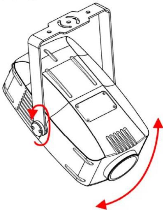
You can adjust the angle of the device with the adjustment screw (04).
01) Turn the adjustment screw (04) counterclockwise to release it.
02) Tilt the device to the desired angle (see Fig. 07).
03) Turn the adjustment screw (04) clockwise to tighten it. Make sure that the device cannot move freely after the adjustment screw (04) is tightened.
natural_image
Technical line drawing of a mechanical housing component with red directional arrows indicating motion (no text or symbols)Fig. 07
4.5. Connecting to Power Supply
DANGER
Electric shock caused by short-circuit
The device accepts AC mains power at 100–240 V and 50/60 Hz. Do not supply power at any other voltage or frequency to the device.
This device falls under IEC protection class I. Make sure that the device is always electrically connected to the ground (earth).
Before connecting the device to the socket-outlet:
- Make sure that the power supply matches the input voltage specified on the information label on the device.
- Make sure that the socket-outlet has ground (earth) connection.
Connect the device to the socket-outlet with the power plug. Do not connect the device to a dimmer circuit, as this may damage the device.
This device is IP66 rated.
- Do not expose the device to conditions that exceed the rated IP class conditions.
- Keep the connectors sealed with the rubber caps when the connectors are not in use.
- Do not connect the cables from above the connectors, if the device is installed outdoors. Make a 'drip loop' in the cable so that rain water cannot enter the device.
- Make sure that the cable run is not too heavy. A heavy cable run can cause damage to the connectors. If the connectors are damaged, their ingress protection (IP) can deteriorate.
4.6. Power Linking of Multiple Devices
This device supports power linking. Power can be relayed to another device via the power OUT connector. Note that the input and the output connectors have different designs: one type cannot be connected to the other.
Power linking of multiple devices must be carried out only by instructed or skilled persons.

WARNING
Incorrect power linking may lead to overload of the electrical circuit and result in serious injuries and damage of property.
To prevent overload of the electrical circuit, when power linking multiple devices:
- Use cables with sufficient current-carrying capacity. The power cable supplied with the device is not suitable for power linking of multiple devices.
- Make sure that the total current draw of the device and all connected devices does not exceed the rated capacity of the power cables and the circuit breaker.
- Do not link more devices on one power link than the maximum recommended number.
Maximum recommended number of devices:
- at 100–120 V: 6 devices Image Spot 150 CW
• at 200–240 V: 12 devices Image Spot 150 CW
5. Setup
5.1. Warnings and Precautions

Attention
Connect all data cables before supplying power.
Disconnect power supply before connecting or disconnecting data cables.
5.2. Stand-alone Setup
When the Image Spot 150 CW is not connected to a controller or to other devices, it functions as a standalone device. It can be operated in auto mode or manually.
For more information about the control modes, refer to 6.6.3. Run Mode on page 25 or 6.6.5. Edit on page 28.
5.3. DMX Connection
5.3.1. DMX-512 Protocol
You need a DMX serial data link to run light shows of one or more devices using a DMX-512 controller or to run synchronized shows of two or more devices set in a master/slave operating mode.
The Image Spot 150 CW has 3-pin DMX signal IN and OUT connectors.
The pin assignment is as follows:
• 3-pin: pin 1 (ground), pin 2 (-), pin 3 (+)
Devices on a serial data link must be daisy-chained in a single line. The number of devices that you can control on one data link is limited by the combined number of the DMX channels of the connected devices and the 512 channels available in one DMX universe.
To comply with the TIA-485 standard, no more than 32 devices should be connected on one data link. In order to connect more than 32 devices on one data link, you must use a DMX optically isolated splitter/booster, otherwise this may result in deterioration of the DMX signal.
Note:
• Maximum recommended DMX data link distance: 300 m
• Maximum recommended number of devices on a DMX data link: 32 devices
5.3.2. DMX Cables
Shielded twisted-pair cables with 3-pin XLR connectors must be used for reliable DMX connection. You can purchase DMX cables directly from your Highlite International dealer or make your own cables.
If you use 3-pin XLR audio cables for DMX data transmission, this may lead to signal degradation and unreliable operation of the DMX network.
When you make your own DMX cables, make sure that you connect the pins and wires correctly as shown in Fig. 08.
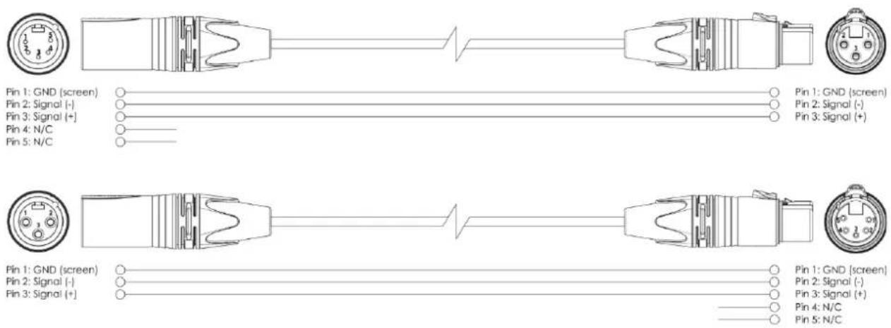
Fig. 08
5.3.3. Master/Slave Setup
The Image Spot 150 CW supports master/slave control mode. To connect multiple devices in master/slave setup, follow the steps below:
01) Connect the first device's DMX OUT connector to the second device's DMX IN connector.
02) Repeat step 1 to connect all devices as shown in Fig. 09.
03) Connect a DMX terminator (120 Ω resistor) to the DMX OUT connector of the last device in the setup.
04) Set the first device on the data link as a master device. See 6.6.3. Run Mode on page 25 or 6.6.5. Edit on page 28 for more information.
05) Set the remaining devices to slave mode. See 6.6.3. Run Mode on page 25 or 6.6.5. Edit on page 28 for more information.
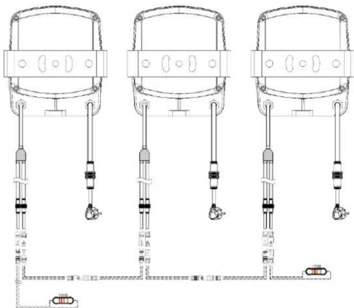
Fig. 09
5.3.4. DMX Linking
To connect multiple devices on one DMX data link, follow the steps below:
01) Use the supplied 3-pin XLR to special 3-pin data cable to connect the DMX OUT connector of the lighting controller to the DMX IN connector of the first device.
02) Connect the first device's DMX OUT connector to the second device's DMX IN connector.
03) Repeat step 2 to connect all devices in a daisy-chain as shown in Fig. 10.
04) Connect a DMX terminator (120 Ω resistor) to the DMX OUT connector of the last device on the data link.

flowchart
graph TD
    A["Device 1"] --> B["Coiled Cable"]
    C["Device 2"] --> D["Coiled Cable"]
    E["Device 3"] --> F["Coiled Cable"]
    G["Device 4"] --> H["Coiled Cable"]
    I["Laptop"] --> J["Battery with 700Ω resistor"]
Fig. 10
5.3.5. DMX Addressing
In a setup with multiple devices, make sure that you set the DMX starting address of each device correctly. The Image Spot 150 CW has 2 personalities: 11 and 14 channels.
If you want to connect multiple devices on one data link and use them in 14-channel mode, for example, follow the steps below:
01) Set the starting address of the 1st device on the data link to 1 (001).
02) Set the starting address of the 2nd device on the data link to 15 (015), as 1 + 14 = 15 .
03) Set the starting address of the 3rd device on the data link to 29 (029) as 15 + 14 = 29 .
04) Continue assigning the starting addresses of the remaining devices by adding each time 14 to the previous number.
Make sure that you do not have any overlapping channels in order to control each Image Spot 150 CW correctly. If two or more devices are addressed similarly, they will work similarly.
6. Operation
6.1. Safety Instructions for Operation

Attention
This device must be used only for the purposes it is designed for.
This device is intended for professional use as an outdoor spot. It is not suitable for households and for general lighting.
Any other use, not mentioned under intended use, is regarded as non-intended and incorrect use.

Attention
Power supply
Before connecting the device to the power supply, make sure that the current, voltage and frequency match the input voltage, current and frequency specified on the information label on the device.
6.2. Control Mode
The Image Spot 150 CW supports the following control modes:
- Stand-alone: Auto, edit 1, edit2
• Master/Slave: Auto, edit 1, edit2
• DMX-512 11, 14 channels
For more information about how to connect the devices, refer to 5. Setup on pages 16–18.
To operate the device manually as a stand-alone device or in a master/slave setup:
See 6.6.3. Run Mode on page 25 or 6.6.5. Edit on page 28 for more information
In auto mode you can run the auto program. To run the auto program:
See 6.6.3. Run Mode on page 25 for more information.
To operate the device with a DMX controller:
- Set the DMX starting address of the device in the DMX Address menu. See 5.3.5. DMX Addressing on page 18 and 6.6.1. DMX Address on page 24.
- Select the DMX channel mode. See 6.6.1. DMX Address on page 24 for more information. See 6.7. DMX Channels on pages 33–34 for complete overview of all DMX channels.
6.3. Control Panel

• Use the MENU function in each menu to exit the current submenu and to return to the Main Menu.
- Use the ENTER button to open the desired menu, to confirm your choice or to set the currently selected value.
• Use the UP/DOWN buttons to navigate through the menus or to increase/decrease numeric values.
6.4. Start-up
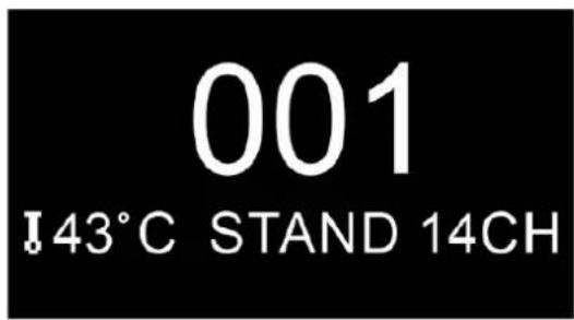
Upon start-up the display shows a splash screen with the brand name of this device. Immediately afterwards the display shows the start screen. The start screen provides information about the currently active operation mode and temperature. Press the MENU button to enter the main menu. The display shows:

Note:
When no button is pressed after 10 seconds of inactivity, the display turns off.
To light up the display, you have to press the MENU button for 3 seconds. Once you have pressed this button, the display lights up.
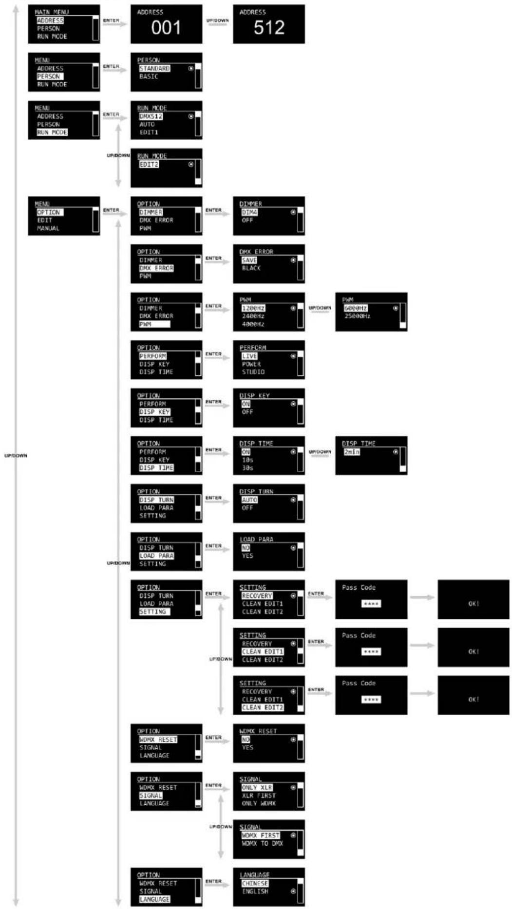
6.5. Menu Overview
flowchart
graph TD
    A["MAIN MENU\nADDRESS\nPERSON\nRUN MODE"] --> B["ENTER"]
    B --> C["ADDRESS 001"]
    C --> D["UPDOWN"]
    E["MENU\nADDRESS\nPERSON\nRUN MODE"] --> F["ENTER"]
    F --> G["PERSON STANDARD BASIC"]
    G --> H["UPDOWN"]
    I["MENU\nADDRESS\nPERSON\nRUN MODE"] --> J["ENTER"]
    J --> K["RUN MODE DMX517 AUTO EDIT1"]
    K --> L["UPDOWN"]
    M["MENU\nOPTION\nEDIT MANUAL"] --> N["ENTER"]
    N --> O["OPTION DIMMER DMX ERROR PWM"]
    O --> P["ENTER"]
    P --> Q["DIMMER DIMM OFF"]
    Q --> R["UPDOWN"]
    S["OPTION PERFORM DISP KEY DISP TIME"] --> T["ENTER"]
    T --> U["EXX ERROR SAVE BLACK"]
    U --> V["UPDOWN"]
    W["OPTION PERFORM DISP KEY DISP TIME"] --> X["ENTER"]
    X --> Y["PWM 1200Hz 2400Hz 4000Hz"]
    Y --> Z["UPDOWN"]
    AA["OPTION PERFORM DISP KEY DISP TIME"] --> AB["ENTER"]
    AB --> AC["PWM 1200Hz 2400Hz 4000Hz"]
    AC --> AD["UPDOWN"]
    AE["OPTION PERFORM DISP KEY DISP TIME"] --> AF["ENTER"]
    AF --> AG["PWM 1200Hz 2400Hz 4000Hz"]
    AG --> AH["UPDOWN"]
    AI["OPTION DISP TURN LOAD PARA SETTING"] --> AJ["ENTER"]
    AJ --> AK["PWM 1200Hz 2400Hz 4000Hz"]
    AK --> AL["UPDOWN"]
    AM["OPTION DISP TURN LOAD PARA SETTING"] --> AN["ENTER"]
    AN --> AO["PWM 1200Hz 2400Hz 4000Hz"]
    AO --> AP["UPDOWN"]
    AQ["OPTION DISP TURN LOAD PARA SETTING"] --> AR["ENTER"]
    AR --> AS["PWM 1200Hz 2400Hz 4000Hz"]
    AS --> AT["UPDOWN"]
    AU["OPTION DOMX RESET SIGNAL LANGUAGE"] --> AV["ENTER"]
    AV --> AW["PWM RESET NO YES"]
    AW --> AX["UPDOWN"]
    AY["OPTION DOMX RESET SIGNAL LANGUAGE"] --> AZ["ENTER"]
    AZ --> BA["SIGNAL ONLY XLR XLR FIRST ONLY WORK"]
    BA --> BB["UPDOWN"]
    BC["OPTION DOMX RESET SIGNAL LANGUAGE"] --> BD["ENTER"]
    BD --> BE["SIGNAL DOMX FIRST DOMX TO DMX"]
    BE --> BF["UPDOWN"]
Image Spot 150 CW

flowchart
graph TD
    A["MENU OPTION EDIT MANUAL"] -->|ENTER| B["EDIT EDIT 1 EDIT 2"]
    B -->|ENTER| C["EDIT 1 STEP-01 STEP-02 STEP-03"]
    C -->|ENTER| D["STEP-01 COLOR ROTA GOBO GOBO ROTA"]
    D -->|ENTER| E["STEP-01 COLOR 255 ROTA GOBO 255 GOBO ROTA 255"]
    C -->|UP/DOWN| F["STEP-01 ANIMATION ANIMA_ROT PRISM"]
    F -->|ENTER| G["STEP-01 ZOOM FOCUS DIMMER"]
    G -->|ENTER| H["STEP-01 STROBE TIME USE"]
    H -->|ENTER| I["STEP-01 STROBE TIME 255 USE YES"]

    J["MENU OPTION EDIT MANUAL"] -->|ENTER| K["MANUAL AUTO TEST MANUAL TEST DEBUG HIDE"]
    K -->|ENTER| L["AUTO TEST ..."]
    L -->|OK!| M["MANUAL TEST COLOR ROTA GOBO GOBO ROTA"]
    M -->|ENTER| N["STEP-01 COLOR 255 ROTA GOBO 255 GOBO ROTA 255"]
    N -->|ENTER| O["STEP-01 ANIMATION ANIMA_ROT PRISM"]
    O -->|ENTER| P["STEP-01 ZOOM FOCUS DIMMER"]
    P -->|ENTER| Q["STEP-01 STROBE"]
    Q -->|ENTER| R["STEP-01 STROBE"]
    R -->|OK!| S["MANUAL TEST DEBUG HIDE NO YES"]
    S -->|ENTER| T["RESET ALL RESET COLOR SYS ZOOM SYS"]
    T -->|OK!| U["MANUAL TEST OTHER"]
    U -->|UP/DOWN| V["MANUAL TEST AUTO TEST MANUAL TEST DEBUG HIDE"]
    V -->|ENTER| W["MANUAL RESET"]
    W -->|ENTER| X["MANUAL TEST AUTO TEST MANUAL TEST DEBUG HIDE"]
Image Spot 150 CW
flowchart
graph TD
    A["MAIN MENU\nINFO\nSERVICE"] -->|ENTER| B["INFO\nFIXTURE HOURS\nTEMPERATURE\VERSION"]
    B -->|ENTER| C["FIXTURE HOURS\n4 h"]
    C --> D["INFO\nFIXTURE HOURS\nTEMPERATURE\VERSION"]
    D -->|ENTER| E["TEMPERATURE\n37 °C"]
    E --> F["INFO\nFIXTURE HOURS\nTEMPERATURE\VERSION"]
    F -->|ENTER| G["VERSION\nDISP:V100\nDATE:2023-03-13"]
    G -->|UP/DOWN| H["VERSION\nMOTO:V104\nDATE:2023-03-13"]
    H --> I["INFO\nRDM\nSYSTEM ERROR"]
    I -->|ENTER| J["RDMLIDLABEL"]
    J -->|ENTER| K["UID\n0x29B40CD00009"]
    K --> L["RDMLIDLABEL"]
    L -->|ENTER| M["LABEL\nImage Spot\n150 CW"]
    M --> N["INFO\nRDM\nSYSTEM ERROR"]
    N -->|ENTER| O["SYSTEM ERROR\nMemory IC ✓\nAngleSens ✓\nTemper ✓"]
    O --> P["SYSTEM ERROR\nColor Rst ✓\nRGOBO Rst ✓\nGOBOR Rst ✓"]
    P --> Q["SYSTEM ERROR\nAnima Rst ✓\nPrism Rst ✓\nFocus Rst ✓"]
    Q --> R["SYSTEM ERROR\nZoom Rst ✓"]
    R --> S["SERVICE\nCOLOR -127\nROTA GOBO -127\nGOBO ROTA -127"]
    S --> T["SERVICE\nCOLOR -127\nROTA GOBO -127\nGOBO ROTA +127"]
    T --> U["SERVICE\nANIMAT -127\nPRISM -127\nFOCUS -127"]
    U --> V["SERVICE\nZOOM -127"]
    V --> W["SERVICE\nZOOM -127"]
    W --> X["SERVICE\nAMAT +127\nPRISM +127\nFOCUS +127"]
6.6. Main Menu Options
The main menu has the following options:

01) Press the MENU button to open the main menu.
02) Press the UP/DOWN buttons to navigate through the main menu.
- Address: See 6.6.1. DMX Address
• Person: See 6.6.2. Person - Run Mode See 6.6.3. Run Mode
- Option: See 6.6.4. Option
• Edit: See 6.6.5. Edit
• Manual: See 6.6.6. Manual - Info: See 6.6.7. Info
• Service: See 6.6.8. System Error
03) Press the ENTER button to open the submenus.
6.6.1. DMX Address
In this menu you can set the DMX starting address of the device and the personality of this device.
01) Press the UP/DOWN buttons to select the DMX starting address of the device. The selection range is 001–512. Refer to 5.3.5. DMX Addressing on page 18 for more information.
02) Press the ENTER button to confirm.
6.6.2. Person
In this menu you can select the DMX channel mode.
01) Press the UP/DOWN buttons to select the DMX channel mode. There are 2 options available:
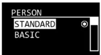
• Standard: 11-channel mode
- Basic: 14-channel mode
02) Press the ENTER button to confirm.
6.6.3. Run Mode
In this menu you can select the desired operating mode.
01) Press the UP/DOWN buttons to select the run mode. There are 4 options available:

- DMX512: DMX mode
• Auto: Built-in programs - Edit1: Custom Program Edit 1 is active, steps 1–30
- Edit2: Custom Program Edit 2 is active, steps 1–30
02) Press the ENTER button to confirm.
6.6.4. Option
In this menu, you can adjust the settings of the device. This menu requires a password.
01) Press the UP/DOWN buttons to select one of the following 12 options:

• DIMMER: Set the dimmer speed. The available options are OFF or DIM4
• DMX ERROR: See 6.6.4.1. DMX Error
- PWM: Set the PWM (Pulse Width Modulation) frequency. The available options are 1200 Hz, 2400 Hz, 4000 Hz, 6000 Hz and 25000 Hz
• PERFORM: Set the speed of the cooling fans: LIVE (auto), STUDIO (slow), POWER (fast)
• DISP KEY: See 6.6.4.2. Disp Key
- DISP TIME: After a set period of inactivity, the display turns off. The period of time can be set to one of the following options: ON, 10s, 30s, 2min
- DISP TURN: The LED display will be inverted 180° (AUTO/OFF)
- LOAD PARA: Upload the parameters of Custom Program 1 and/or 2 (EDIT1 or EDIT2) from the master device to the slave device(s)
- SETTING: See 6.6.4.3. Settings for more information
- WDMX RESET: Reset the wireless connection and clear all messages of the receiver (NO/YES)
• SIGNAL: See 6.6.4.4. Signal for more information
- LANGUAGE Set the language of the display. The available options are English or Chinese
02) Press the ENTER button to confirm.
6.6.4.1. DMX Error
In this submenu you can determine the behavior of the device in case of a DMX failure.
01) Press the UP/DOWN buttons select one of the following 2 options:
- SAVE: The device will use the last properly received DMX signal
- BLACK: The device will black out the light output
02) Press the ENTER button to confirm.
6.6.4.2. Display Key
In this submenu you can activate the display keylock.
01) Press the UP/DOWN buttons to toggle between ON and OFF.
- ON: The display lock is on. The display will be locked after 30 seconds of inactivity. After 5 more seconds the display will turn off. To access the main menu, you need to enter the password. The default password is pressing the UP/DOWN buttons in the following order: UP, DOWN, UP, DOWN, then press ENTER
• OFF: The access to the main menu remains unlocked after the display turns off
02) Press the ENTER button to confirm.
Note:
If you turn off the display lock, this will not affect the submenus which by default require a password.
6.6.4.3. Setting
In this submenu you can reset some of the parameters of the device.
01) Press the UP/DOWN buttons to select one of the following 3 options:

- RECOVERY: Restore the default factory settings of the device. This submenu requires a password. The default password is pressing the UP/DOWN buttons in the following order: UP, DOWN, UP, DOWN, then press ENTER
- CLEAN EDIT1: Reset Custom Program 1. All values set in EDIT 1 will be cleared. See 6.6.5. Edit on pages 28–29 for more information. This submenu requires a password. The default password is pressing the UP/DOWN buttons in the following order: UP, DOWN, UP, DOWN, then press ENTER
- CLEAN EDIT2: Reset Custom Program 2. All values set in EDIT 2 will be cleared. See 6.6.5. Edit on pages 28–29 for more information. This submenu requires a password. The default password is pressing the UP/DOWN buttons in the following order: UP, DOWN, UP, DOWN, then press ENTER
02) Press the ENTER button to confirm.
6.6.4.4. Signal
In this submenu you can set the signal preferences when wireless DMX is enabled.
01) Press the UP/DOWN buttons to select one of the following 5 options:

- ONLY XLR: DMX signal is only received via wired XLR cable
- XLR FIRST: DMX signal is received via wired XLR cable (1 st priority). When DMX signal is lost, the device will keep playing via WDMX (2 nd priority). The device must be paired with WDMX
- ONLY WDMX: DMX signal is only received via Wireless DMX. Device needs to be paired via WDMX
- WDMX FIRST: DMX signal is received via WDMX (1 st priority). The device must be paired with WDMX. When DMX signal is lost, the device will keep playing via wired XLR cable (2 nd priority)
- WDMX TO WDMX: WDMX signal is received via WDMX. When linking multiple devices, you can set a wireless connection between the first device and the lighting controller and link the rest of the devices to the first device via WDMX
02) Press the ENTER button to confirm.
6.6.5. Edit
In this menu you can edit the 2 custom programs.
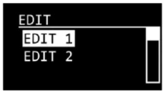
To edit the custom programs:
01) Press the UP/DOWN buttons to select the custom program you want to edit: EDIT1 or EDIT2.
02) Press the ENTER button to confirm and open the submenu with the scenes. Each custom program has 30 scenes, which can be edited:
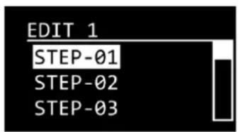


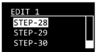
03) Press the UP/DOWN buttons to select the desired scene.
04) Press the ENTER button to confirm and open the submenu with the settings for the respective scene.
05) Press the UP/DOWN buttons to select one of the following 12 options:

• COLOR: Set the position of the color wheel. The adjustment range is 0–255
- ROTA GOBO: Set the position of the gobo wheel. The adjustment range is 0–255
- GOBO ROTA: Set the rotation speed of the gobo wheel. The adjustment range is 0–255
• ANIMATION: Set the position of the effect wheel. The adjustment range is 0–255
• ANIMA_ROT Set the rotation speed of the effect wheel. The adjustment range is 0–255
- PRISM Set the rotation speed of the prism. The adjustment range is 0–255
• ZOOM: Set the zoom adjustment. The adjustment range is 0–255
- FOCUS: Set the focus adjustment. The adjustment range is 0–255
- DIMMER: Set the intensity of the dimmer. The adjustment range is 0–255, from low to high intensity
• STROBE: Add strobe effect. The adjustment range is 0–25, from OFF to high frequency - TIME: Set the duration of the step (0–255, from 0,1 to approximately 25 seconds)
- USE: Include the step in the custom program (YES/NO). If you select NO, the step will be excluded from the playback of the custom program
06) Press the ENTER button to confirm.
07) Press the UP/DOWN buttons to increase/decrease the values.
08) Press the ENTER button to set the value and to move to the next setting.
09) Repeat steps 7–8 to set all parameters in the scene.
10) Press the MENU button to return to the submenu with the steps.
11) Repeat steps 3–9 to edit the remaining steps of the selected custom program.
Note:
For each custom program you can create 30 steps, which makes it possible to create 60 customized scenes in total.
6.6.6. Manual
In this menu you can manually adjust and reset the parameters of the device.
01) Press the UP/DOWN buttons to select one of the following 4 options:

- AUTO TEST: Perform auto test of parameters of the device
• MANUAL TEST: See 6.6.6.1. Manual Test - DEBUG HIDE: This option is not relevant to the use and operation of the device
- RESET: See 6.6.6.2. Reset
02) Press the ENTER button to confirm.
6.6.6.1. Manual Test
In this submenu you can manually adjust the parameters of the device.
01) Press the UP/DOWN buttons to select one of the following 10 options:

- COLOR: Set the position of the color wheel. The adjustment range is 0–255
- ROTA GOBO: Set the position of the gobo wheel. The adjustment range is 0–255
- GOBO ROTA: Set the rotation speed of the gobo wheel. The adjustment range is 0–255
• ANIMATION: Set the position of the effect wheel. The adjustment range is 0–255
• ANIMA_ROT Set the rotation speed of the effect wheel. The adjustment range is 0–255 - PRISM Set the rotation speed of the prism. The adjustment range is 0–255
• ZOOM: Set the zoom adjustment. The adjustment range is 0–255 - FOCUS: Set the focus adjustment. The adjustment range is 0–255
- DIMMER: Set the intensity of the dimmer. The adjustment range is 0–255, from low to high intensity
- STROBE: Add strobe effect. The adjustment range is 0–25, from OFF to high frequency
02) Press the ENTER button to confirm.
03) Press the UP/DOWN buttons to increase/decrease the values.
04) Press the ENTER button to set the value.
6.6.6.2. Reset
In this submenu you can manually reset the parameters of the device.
01) Press the UP/DOWN buttons to select one of the following 4 options:

• ALL RESET: Reset all parameters
- COLOR SYS: Color wheel, gobo wheel, rotating gobo reset
• ZOOM SYS: Zoom, focus reset
- OTHER: Prism, effect wheel reset
02) Press the ENTER button to confirm and perform the reset.
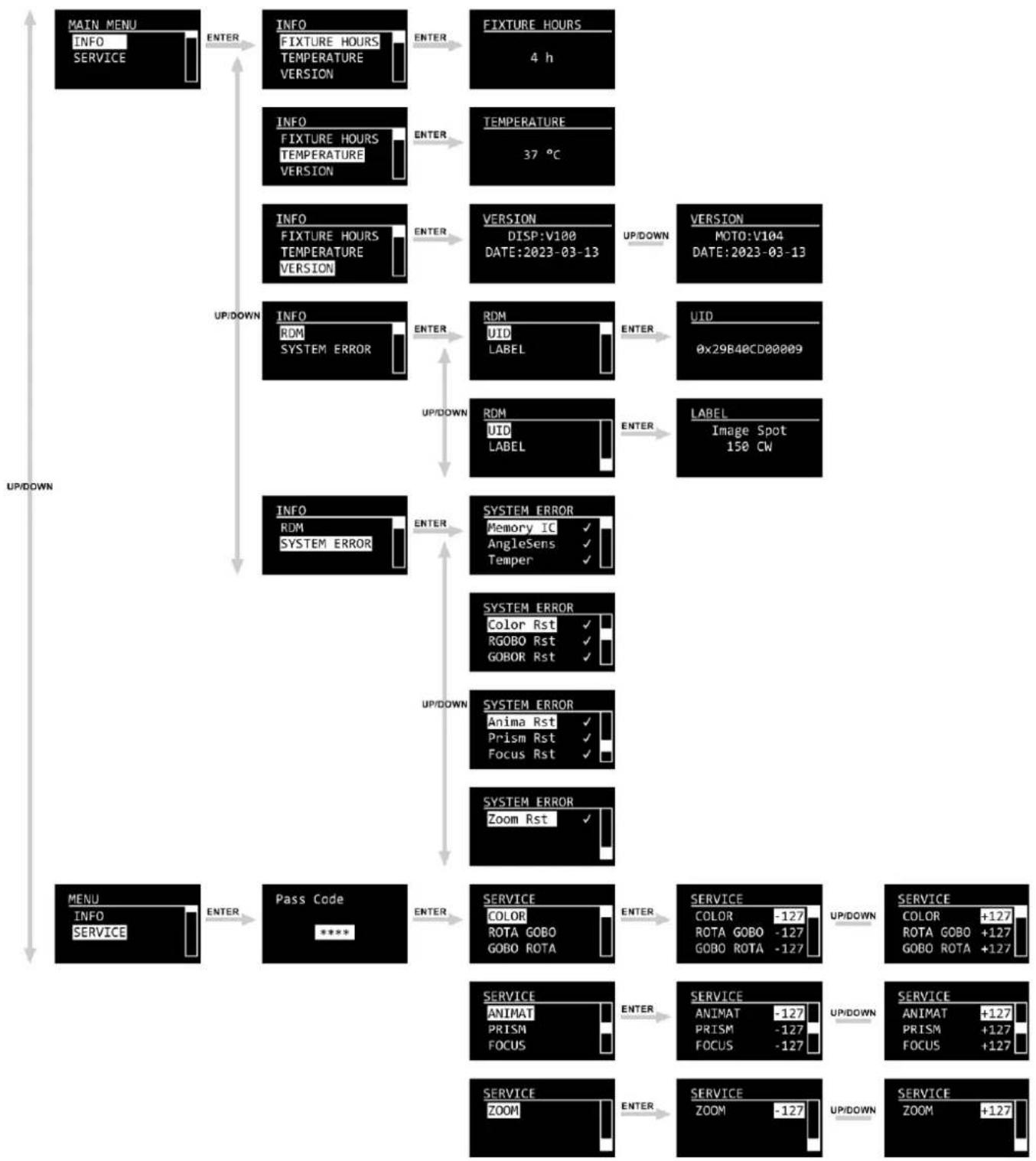
6.6.7. Info
In this menu you can view the parameters of the device.
01) Press the UP/DOWN buttons to select one of the following 5 options:

- FIXTURE HOURS: Shows the total hours of operation of the device
• TEMPERATURE: Provides information about the temperature of the LEDs - VERSION: Provides information about the firmware version of the following parameters: DISPLAY and MOTO. Press the UP/DOWN buttons to scroll through the 2 screens
- RDM: Shows the UID number and name (LABEL) of the device
- SYSTEM ERROR: See 6.7.7.1. System Error
02) Press the ENTER button to confirm.
6.6.7.1. System Error
In this submenu you can view whether there are any system errors.
Press the UP/DOWN buttons to scroll through the following 10 options:

The displayed parameters are:
- MEMORY IC
- ANGLE SENSOR
• TEMPERATURE - COLOR RESET
- RGOBO RESET
- GOBOR RESET
• ANIMATION RESET - PRISM RESET
- FOCUS RESET
- ZOOM RESET
If there are no errors, the display shows (OK) next to the parameter. If there are errors, the display shows ERROR. Contact your Highlite International dealer if there is a system error.
6.6.8. Service
In this menu you can calibrate some of the parameters of the device. This menu requires a password. The default password is pressing the UP/DOWN buttons in the following order: UP, DOWN, UP, DOWN, then press ENTER
01) Enter the password.
02) Press the ENTER button to confirm the password and enter the submenu.
03) Press the UP/DOWN buttons to select one of the following 7 options:

- COLOR: Adjust the home position of the color wheel. The adjustment range is between -127 and +127
- ROTA GOBO: Adjust of the home position of the rotating gobo wheel. The adjustment range is between -127 and +127
- GOBO ROTA: Adjust of the home position of the rotation position of the gobo wheel. The adjustment range is between -127 and +127
- ANIMAT: Adjust of the home position of the effect wheel. The adjustment range is between -127 and +127
- PRISM: Adjust of the home position of the effect wheel. The adjustment range is between -127 and +127
- FOCUS: Adjust of the home position of the effect wheel. The adjustment range is between -127 and +127
- ZOOM: Adjust of the home position of the effect wheel. The adjustment range is between -127 and +127
04) Press the ENTER button to confirm.
05) Press the UP/DOWN buttons to increase/decrease the value or make a selection.
06) Press the ENTER button to set the value or confirm.
6.7. DMX Channels
6.7.1. 11, 14 Channels
| 11 CH | 14 CH | Function | Value | Setting |
| 1 | 1 | Master Dimmer | 000-255 | From low to high intensity (0-100 %) |
| 2 | Dimmer Fine | 000-255 | From low to high intensity (0-100 %) | |
| 2 | 3 | Strobe | 000-009 | No function |
| 010-099 | Linear strobe, from low to high frequency (0-25 Hz) | |||
| 100-109 | Shutter open | |||
| 110-179 | Pulse strobe, from slow to fast | |||
| 180-189 | Shutter open | |||
| 190-255 | Random strobe slow to fast | |||
| 3 | 4 | Color wheel | 000-007 | White |
| 008-015 | Red | |||
| 016-023 | Light blue | |||
| 024-031 | Green | |||
| 032-039 | Pink | |||
| 040-047 | Yellow | |||
| 048-191 | Color wheel indexing | |||
| 192-222 | Clockwise rotation, from fast to slow | |||
| 223-224 | Stop | |||
| 225-255 | Counter-clockwise rotation, from slow to fast | |||
| 5 | Color Wheel Fine | 000-255 | Color wheel positioning fine-tuning | |
| 4 | 6 | Gobo wheel | 000-010 | Open |
| 011-024 | Gobo 1 | |||
| 025-038 | Gobo 2 | |||
| 039-052 | Gobo 3 | |||
| 053-066 | Gobo 4 | |||
| 067-080 | Rotating Gobo 1 shake effect, from slow to fast | |||
| 081-094 | Rotating Gobo 2 shake effect, from slow to fast | |||
| 095-108 | Rotating Gobo 3 shake effect, from slow to fast | |||
| 109-122 | Rotating Gobo 4 shake effect, from slow to fast | |||
| 123-127 | Open | |||
| 128-190 | Clockwise rotation (CW) gobo flow from fast to slow | |||
| 191-192 | Stop | |||
| 193-255 | Counter-clockwise rotation (CCW) gobo flow from slow to fast | |||
| 5 | 7 | Gobo rotation | 000-121 | Gobo Indexing |
| 122-125 | Stop | |||
| 126-165 | Rotating gobo shake effect, from slow to fast | |||
| 166-170 | Stop | |||
| 171-210 | Clockwise gobo rotation, from fast to slow | |||
| 211-215 | Stop | |||
| 216-255 | Counter-clockwise gobo rotation, from slow to fast | |||
| 6 | 8 | Effect wheel | 000-255 | Effect wheel location |
| 7 | 9 | Effect wheel rotation | 000-010 | No rotation |
| 011-131 | Clockwise effect wheel rotation, from fast to slow | |||
| 132-134 | Stop | |||
| 135-255 | Counter-clockwise effect wheel rotation, from slow to fast | |||
| 8 | 10 | Prism (4-facet) | 000-010 | Open |
| 011-155 | Prism indexing | |||
| 156-157 | Stop | |||
| 158-205 | Clockwise prism rotation, from fast to slow | |||
| 206-207 | Stop | |||
| 208-255 | Counter-clockwise prism rotation, from slow to fast | |||
| 9 | 11 | Zoom | 000–255 | Zoom adjustment |
| 10 | 12 | Focus | 000–255 | Gradual focus adjustment, 0–100 % |
| 13 | Focus Fine | 000–255 | Gradual focus adjustment, 0–100 % | |
| 11 | 14 | Function | 000–010 | No function |
| 011–060 | Reserved | |||
| 061–070 | Live (Auto) | |||
| 071–080 | Studio (Slow) | |||
| 081–090 | Power (Fast) | |||
| 091–100 | Reserved | |||
| 101–110 | Dimmer off | |||
| 111–120 | Dimmer DIM4 | |||
| 121–150 | Reserved | |||
| 151–160 | 1200Hz | |||
| 161–170 | 2400Hz | |||
| 171–180 | 4000Hz | |||
| 181–190 | 6000Hz | |||
| 191–200 | 25000Hz | |||
| 201–210 | All reset | |||
| 211–220 | Color wheel, gobo wheel, rotating gobo reset | |||
| 221–230 | Zoom, focus reset | |||
| 231–240 | Prism, dynamic effect wheel reset | |||
| 241–255 | Reserved |
6.8. Rotating Gobo Wheel, Effect Wheel and Color Wheel

natural_image
Circular abstract pattern with white circular shapes and dot textures on black background (no text or symbols)Fig. 12

natural_image
Circular abstract pattern with radiating white wavy lines on a black background, resembling a stylized sun or flame design (no text or symbols)Fig. 13

natural_image
Colorful circular segment with six segments (yellow, magenta, green, cyan, red, white) and a central dot, no text or symbols present.Fig. 14
6.8.1. Replacing a Gobo from the Rotating Gobo Wheel

DANGER
Electric shock caused by dangerous voltage inside
There are areas within the device where dangerous touch voltage may be present.
- Disconnect the device from electrical power supply before service and maintenance, and when the device is not in use.
- Allow the device to cool down before opening the cover.
- Use for replacement only gobos that match the specifications below. Using custom gobos that do not match those specifications may result in damage to the device. Any damage to the device as a result of using a custom gobo is not covered under warranty.
- Do not touch the glass gobo with bare fingers to avoid leaving fingerprints. Handle the gobo only by the gobo carrier, or wear protective gloves. If you touch the glass, clean with a soft lint-free cloth and rubbing alcohol.
To replace a rotating gobo, follow the steps below:
01) Disconnect the device from the mains and allow it to cool completely.
02) Set the device in horizontal position with the lens facing forward.
03) Loosen the 6 hex screws on the maintenance cover, as shown in Fig. 15.

natural_image
Technical line drawing of a mechanical component with mounting holes and a separate L-shaped bracket (no text or symbols)Fig. 15
04) Carefully remove the head cover from the housing to get access to the rotating gobo wheel.
05) Turn the rotating gobo wheel by hand until you reach the gobo which you want to replace.
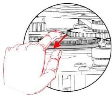
06) Gently lift the gobo holder a bit up and pull it out from the rotating gobo wheel, as shown in Fig. 16 and Fig. 17.

natural_image
Hand pointing at a circular architectural or mechanical structure with a red upward arrow (no text or symbols)Fig. 16
natural_image
Hand holding a tool interacting with a mechanical component inside a circular frame (no text or symbols visible)Fig. 17
07) Very carefully take the gobo out of the gobo holder with a pair of pliers.
08) Take the gobo out of the gobo holder. Do not touch the gobo with bare fingers.
09) Put the new gobo in the gobo holder.
10) Carefully put the pinchcock back. You can use a pair of pliers to press the pinchcock a little bit together. See 6.8.3. Glass Gobo Orientation on page 37 for more information.
11) Put the gobo holder back under the pressing snap and push it back into position.
12) Replace the maintenance cover and fasten all 6 hex screws.
6.8.2. Gobo Size

Fig. 18
6.8.3. Glass Gobo Orientation
Coated glass gobos are inserted with the coating against the rim of the holder. Textured gobos are inserted with the smooth side pointing away from the holder. This provides the best results when combining rotating gobos.

Fig. 19
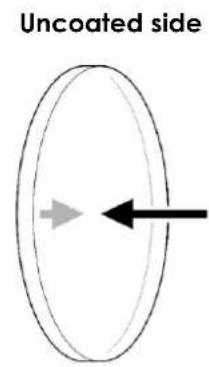
Fig. 20
When an object is held up to the coated side, there is no space between the object and its reflection. The back edge of the gobo cannot be seen when looking through the coated side.
When an object is held up to the uncoated side, there is a space between the object and its reflection. The back edge of the gobo can be seen when looking through the uncoated side.
6.9. RDM Information
This device supports RDM. Refer to 6.8.2. Supported RDM PIDs (Parameter IDs) for more information.
6.9.1. RDM Details
- Responder: 29B4:0CDxxxxx
• Manufacturer's ID: Showtec (Highlite International B.V.)
• Manufacturer Label: Arpecta - Model Description: Image Spot 150 CW
- Model ID: 205
• Device Label: Image Spot 150 CW
6.9.2. Supported RDM PIDs (Parameter IDs)
| Parameter ID | Value | Required | GET | SET |
| COMMS_STATUS | 0x0015 | * | * | |
| STATUS_MESSAGES | 0x0030 | * | ||
| STATUS_ID_DESCRIPTION | 0x0031 | * | ||
| CLEAR_STATUS_ID | 0x0032 | * | ||
| SUPPORTED_PARAMETERS | 0x0050 | * | * | |
| DEVICE_MODEL_DESCRIPTION | 0x0080 | * | ||
| MANUFACTURER_LABEL | 0x0081 | * | ||
| DEVICE_LABEL | 0x0082 | * | * | |
| LANGUAGE_CAPABILITIES | 0x00A0 | * | ||
| LANGUAGE | 0x00B0 | * | * | |
| DMX_PERSONALITY | 0x00E0 | * | * | |
| DMX_PERSONALITY_DESCRIPTION | 0x00E1 | * | ||
| DMX_START_ADDRESS | 0x00F0 | * | * | * |
| SENSOR_DEFINITION | 0x0200 | * | ||
| SENSOR_VALUE | 0x0201 | * | * | |
| RECORD_SENSORS | 0x0202 | * | ||
| CURVE | 0x0343 | * | * | |
| CURVE_DESCRIPTION | 0x0344 | * | * | |
| MODULATION_FREQUENCY | 0x0347 | * | * | |
| MODULATION_FREQUENCY_DESCRIPTION | 0x0348 | * | * |
7. Troubleshooting
This troubleshooting guide contains solutions to problems which can be carried out by an ordinary person. The device does not contain user-serviceable parts.
Unauthorized modifications to the device will render the warranty void. Such modifications may result in injuries and material damage.
Refer servicing to instructed or skilled persons. Contact your Highlite International dealer in case the solution is not described in the table.
| Problem | Probable cause(s) | Solution |
| The device does not function at all | No power to the device | Make sure the power is switched on and cables are plugged in |
| Main fuse is blown | Disconnect the device and contact your Highlite International dealer | |
| The device does not respond to DMX control | The controller is not connected | Connect the controller |
| The signal is reversed. The 3-pin/5-pin DMX OUT of the controller does not match the DMX IN of the device | Install a phase-reversing cable between the controller and the device | |
| The controller is defective | Try using another controller | |
| The device responds erratically to DMX control | Bad data link connection | Examine connections and cables.Correct poor connections. Repair or replace damaged cables |
| The data link is not terminated with a 120 Ω termination plug | Insert a termination plug in the DMX OUT connector of the last device on the link | |
| Incorrect addressing | Check address settings and correct, if necessary | |
| In case of a setup with multiple devices, one of the devices is defective and disturbs data transmission on the link | To find out the defective device, bypass one device at a time until normal operation is restored | |
| No light or LEDs cut out intermittently | LEDs are damaged | Disconnect the device and contact your Highlite International dealer |
| The power supply settings do not match local AC voltage and frequency | Disconnect the device. Check the settings and correct, if necessary |
8. Maintenance
8.1. Safety Instructions for Maintenance
DANGER
Electric shock caused by dangerous voltage inside
Disconnect power supply before servicing or cleaning.
8.2. Preventive Maintenance

Attention
Before each use, examine the device visually for any defects.
Make sure that:
- All screws used for installing the device or parts of the device are tightly fastened and are not corroded.
- The safety devices are not damaged.
• There are no deformations on housings, fixations and installation points. - The lens is not cracked or damaged.
- The power cables are not damaged and do not show any material fatigue.
8.2.1. Basic Cleaning Instructions
The external lens of the device must be cleaned periodically in order to optimize the light output. The cleaning schedule depends on the conditions at the site where the device is installed. When smoke or fog machines are used at the site, the device will need more frequent cleaning. On the other hand, if the device is installed in well-ventilated area, it will need less frequent cleaning. To establish a cleaning schedule, examine the device at regular intervals during the first 100 hours of operation.
To clean the device, follow the steps below:
01) Disconnect the device from the electrical power supply.
02) Allow the device to cool down for at least 15 minutes.
03) Remove the dust collected on the external surface with dry compressed air and a soft brush.
04) Clean the lens with a damp cloth. Use a mild detergent solution.
05) Dry the lens carefully with a lint-free cloth.
06) Clean the DMX and other connections with a damp cloth.

Attention
- Do not immerse the device in liquid.
- Do not use alcohol or solvents.
- Make sure that the connections are fully dry before connecting the device to the power supply and to other devices.
8.2.2. Draining Condensation Water
The Image Spot 150 CW is IP66 rated. The device can resist water jets. If the device is exposed to extreme humid conditions during servicing, condensation may collect inside the device. This can happen also during transportation, if the device is exposed to extreme temperature variations.
If condensation water collects inside the device, follow the steps below to remove the condensation water:
01) Carefully remove the protective vent (02) with a wrench (16 mm).

Fig. 21
02) Let the device operate at full output for 60 minutes.
03) Let the device cool down for 30 minutes.
04) Install the protective vent (02) back in place. Make sure that you do not overtighten it.
8.3. Corrective Maintenance
The device does not contain user-serviceable parts. Do not open the device and do not modify the device.
Refer repairs and servicing to instructed or skilled persons. Contact your Highlite International dealer for more information.
9. Deinstallation, Transportation and Storage
9.1. Instructions for Deinstallation

WARNING
Incorrect deinstallation can cause serious injuries and damage of property.
- Let the device cool down before dismounting.
- Disconnect power supply before deinstallation.
- Always observe the national and site-specific regulations during deinstallation and derigging of the device.
- Wear personal protective equipment in compliance with the national and site-specific regulations.
9.2. Instructions for Transportation
- Use the original packaging to transport the device, if possible.
- Always observe the handling instructions printed on the outer carton box, for example: "Handle with care", "This side up", "Fragile".
9.3. Storage
- Clean the device before storing. Follow the cleaning instructions in chapter 8.2.1. Basic Cleaning Instructions on page 40.
- Store the device in the original packaging, if possible.
10. Disposal

Correct disposal of this product
Waste Electrical and Electronic Equipment
This symbol on the product, its packaging or documents indicates that the product shall not be treated as household waste. Dispose of this product by handing it to the respective collection point for recycling of electrical and electronic equipment. This is to avoid environmental damage or personal injury due to uncontrolled waste disposal. For more detailed information about recycling of this product contact the local authorities or the authorized dealer.
11. Approval


Check the respective product page on the website of Highlite International (www.highlite.com) for an available declaration of conformity.
- Image Spot 150 CW
- Preface
- Table of contents
- Introduction......4
- Safety....6
- Description of the Device 9
- Installation....12
- Setup....16
- Operation....19
- Introduction
- Before Using the Product
- Intended Use
- Product Lifespan
- LEDs Lifespan
- Text Conventions
- Symbols and Signal Words
- Electrical hazard
- Symbols on the Information Label
- Safety
- Warnings and Safety Instructions
- WARNING
- Risk of epileptic shock
- Attention
- Power supply
- General safety
- For professional use only
- This device shall be used only for the purposes it is designed for.
- Make sure that:
- Requirements for the User
- Description of the Device
- Front View
- Back View
- Product Specifications
- Optional Accessories
- Dimensions
- Installation
- Safety Instructions for Installation
- Personal Protective Equipment
- Installation Site Requirements
- Rigging
- CAUTION
- Angle Adjustment
- Connecting to Power Supply
- Power Linking of Multiple Devices
- Setup
- Warnings and Precautions
- Stand-alone Setup
- DMX Connection
- DMX-512 Protocol
- Note:
- DMX Cables
- Master/Slave Setup
- DMX Linking
- DMX Addressing
- Operation
- Safety Instructions for Operation
- Control Mode
- Control Panel
- Start-up
- Main Menu Options
- DMX Address
- Person
- Run Mode
- Option
- DMX Error
- Display Key
- Setting
- Signal
- Edit
- Manual
- Manual Test
- Reset
- Info
- System Error
- Service
- DMX Channels
- 11, 14 Channels
- Rotating Gobo Wheel, Effect Wheel and Color Wheel
- Replacing a Gobo from the Rotating Gobo Wheel
- DANGER
- Electric shock caused by dangerous voltage inside
- Gobo Size
- Glass Gobo Orientation
- RDM Information
- RDM Details
- Troubleshooting
- Maintenance
- Safety Instructions for Maintenance
- Preventive Maintenance
- Basic Cleaning Instructions
- Draining Condensation Water
- Corrective Maintenance
- Deinstallation, Transportation and Storage
- Instructions for Deinstallation
- Instructions for Transportation
- Storage
- Disposal
- Correct disposal of this product
- Approval
Brand : Artecta
Model : Image Spot 150 CW
Category : Lighting