
Par 30 Tracklight - Warm on Dim - Lighting Artecta - Free user manual and instructions
Find the device manual for free Par 30 Tracklight - Warm on Dim Artecta in PDF.

| Product Type | Architectural Track Light Spot |
| Model | Par 30 Tracklight – Warm on Dim V1 |
| Product Code | A0320072 |
| Dimensions (with track adapter) | 224 x 146 x 255 mm (L x W x H) |
| Weight (with track adapter) | 0.6 kg |
| Input Voltage | 240 V AC, 50/60 Hz |
| Power Consumption | 23 W (at full output) |
| Power Factor Correction (PFC) | 0.96 |
| Light Source | 20 W LED |
| Dimmer Type | External, TRIAC |
| Beam Angle | 45° |
| Luminous Flux | 1100 lm |
| Color Temperature Range | 1800 K (at 5%) – 2700 K (at 100%) |
| Color Rendering Index (CRI) | >95 |
| IP Rating | IP20 (Indoor use only) |
| Housing Material | Extruded aluminum, black |
| Cooling | Natural convection |
| Maximum Ambient Temperature | 40 °C |
| Minimum Ambient Temperature | -5 °C |
| Minimum Distance from Flammable Surfaces | 0.5 m |
| Minimum Distance to Lighted Object | 0.5 m |
| Track Adapter | 3-phase, 220-250 V, 10 A, max. load 100 N |
| Included Accessories | Color frame (installed), user manual |
| Protection Class | I (requires ground connection) |
| Intended Use | Professional indoor use (shops, exhibitions, showrooms) |
Frequently Asked Questions - Par 30 Tracklight - Warm on Dim Artecta
User questions about Par 30 Tracklight - Warm on Dim Artecta
0 question about this device. Answer the ones you know or ask your own.
Ask a new question about this device
Download the instructions for your Lighting in PDF format for free! Find your manual Par 30 Tracklight - Warm on Dim - Artecta and take your electronic device back in hand. On this page are published all the documents necessary for the use of your device. Par 30 Tracklight - Warm on Dim by Artecta.
USER MANUAL Par 30 Tracklight - Warm on Dim Artecta
natural_image
Technical line drawing of a mechanical device with mounting bracket and housing (no text or symbols)ENGLISH
Par 30 Tracklight - Warm on Dim V1
Product code: A0320072
Preface
Thank you for purchasing this Arpecta product.
The purpose of this user manual is to provide instructions for the correct and safe use of this product.
Keep the user manual for future reference as it is an integral part of the product. The user manual shall be stored at an easily accessible location.
This user manual contains information concerning:
- Safety instructions
- Intended and non-intended use of the device
• Installation and operation of the device - Maintenance procedures
- Troubleshooting
- Transport, storage and disposal of the device
Non-observance of the instructions in this user manual may result in serious injuries and damage of property.
©2021 Arpecta. All rights reserved.
No part of this document may be copied, published or otherwise reproduced without the prior written consent of Highlite International.
Design and product specifications are subject to change without prior notice.
For the latest version of this document or other language versions, please visit our website www.highlite.com or contact us at service@highlite.com.
Highlite International and its authorized service providers are not liable for any injury, damage, direct or indirect loss, consequential or economic loss or any other loss arising from the use of, or inability to use or reliance on the information contained in this document.
Table of contents
1. Introduction......3
1.1. Before Using the Product ....3
1.2. Intended Use....3
1.3. LEDs Lifespan 3
1.4. Text Conventions....3
1.5. Symbols and Signal Words....4
1.6. Symbols on the Information Label 4
2. Safety 4
2.1. Warnings and Safety Instructions ....5
2.2. Requirements for the User....6
3. Description of the Device....7
3.1. Front View 7
3.2. Dimensions....7
3.3. Product Specifications ....8
4. Installation and Deinstallation ....9
4.1. Safety Instructions....9
4.2. Personal Protective Equipment 9
4.3. Installation Site Requirements 9
4.4. Mounting....9
4.5. Dismounting....11
4.6. Direction Adjustment....12
4.7. Color Frame....12
4.8. Connecting to Power Supply....12
5. Troubleshooting ....13
6. Maintenance ....13
6.1. Safety Instructions for Maintenance....13
6.2. Preventive Maintenance....13
6.2.1. Basic Cleaning Instructions....13
6.3. Corrective Maintenance....14
7. Transportation and Storage....14
7.1. Instructions for Transportation 14
7.2. Storage....14
8. Disposal 14
9. Approval....14
1. Introduction
1.1. Before Using the Product

Important Read and follow the instructions in this user manual before installing, operating or servicing this product.
The manufacturer will not accept liability for any resulting damages caused by the non-observance of this manual.
After unpacking, check the contents of the box. If any parts are missing or damaged, contact your Highlite International dealer.
Your shipment includes:
- Arpecta Par 30 Tracklight – Warm on Dim (including track adapter)
• Color frame (installed) - User manual

natural_image
Technical line drawing of a mechanical device with mounting bracket and housing (no text or symbols)Fig. 01
1.2. Intended Use
This device is intended for professional use as an architectural light spot. It is suitable for indoor installation in shops, exhibition halls, showrooms and similar venues. This device is not suitable for households.
Any other use, not mentioned under intended use, is regarded as non-intended and incorrect use.
1.3. LEDs Lifespan
The light output of the LEDs gradually decreases over time (lumen depreciation). High operating temperatures contribute to this process. You can extend the lifespan of the LEDs by providing adequate ventilation and operating the LEDs at the lowest possible brightness.
1.4. Text Conventions
Throughout the user manual the following text conventions are used:
- References: References to chapters and parts of the device are in bold lettering, for example: "Refer to 2. Safety", "turn the adjustment handle (05)"
• Notes: Note: (in bold lettering) is followed by useful information or tips
1.5. Symbols and Signal Words
Safety notes and warnings are indicated throughout the user manual by safety signs.
Always follow the instructions provided in this user manual.

| DANGER | Indicates an imminently hazardous situation which, if not avoided, will result in death or serious injury. |
| WARNING | Indicates a potentially hazardous situation which, if not avoided, could result in death or serious injury. |
| CAUTION | Indicates a potentially hazardous situation, which, if not avoided, may result in minor or moderate injury. |
| Attention | Indicates important information for the correct operation and use of the product. |
Important Read and observe the instructions in this document.
Electrical hazard
Provides important information about the disposal of this product.
1.6. Symbols on the Information Label
This product is provided with an information label. The information label is located on the mounting bracket.
The information label contains the following symbols:

This device is designed for indoor use.
This device falls under IEC protection class I.
This device shall not be treated as household waste.
2. Safety

Important Read and follow the instructions in this user manual before installing, operating or servicing this product.
The manufacturer will not accept liability for any resulting damages caused by the non-observance of this manual.
2.1. Warnings and Safety Instructions

DANGER
Danger for children
For adult use only. The device must be installed beyond the reach of children.
- Do not leave various parts of the packaging (plastic bags, polystyrene foam, nails, etc.) within children's reach. Packaging material is a potential source of danger for children.

DANGER
Electric shock caused by dangerous voltage inside
There are areas within the device where dangerous touch voltage may be present.
- Do not open the device or remove any covers.
- Do not operate the device if the covers or the housing is open. Before operation, check if the housing is firmly closed and all screws are tightly fastened.
- Disconnect the device from electrical power supply before service and maintenance.

DANGER
Electric shock caused by short-circuit
This device falls under IEC protection class I.
- Make sure that the device is electrically connected to ground (earth). Connect the device only to a track system with ground (earth) connection.
- Do not cover the ground (earth) connection.
- Do not bypass the thermostatic switch or fuses.
- For replacement use fuses of the same type and rating only.
- Do not modify, bend, mechanically strain, put pressure on, pull or heat up the interconnecting power cable.
- Make sure that the interconnecting power cable is not crimped or damaged. Examine the power cable periodically for any defects.
- Do not immerse the device in water or other liquids. Do not install the device in a location where flooding may occur.

Attention
Power supply
Before connecting the device to the power supply, make sure that the current, voltage and frequency match the input voltage, current and frequency specified on the information label on the device.

Attention
General safety
- Do not shake the device. Avoid brute force when installing or operating the device.
- If the device fails to work properly, discontinue the use immediately.

Attention
This device shall be used only for the purposes it is designed for.
This device is intended for professional use as an architectural light spot. It is suitable for indoor installation in shops, exhibition halls, showrooms and similar venues.
- This device is not suitable for households.
- This device does not contain user-serviceable parts. Unauthorized modifications to the device will render the warranty void. Such modifications may result in injuries and material damage.

Attention
Before use, examine the device visually for any defects.
Make sure that:
• There are no deformations on housings, fixations and installation points.
- The lens is not cracked or damaged.
- The interconnecting power cable is not damaged and does not show any material fatigue.

Attention
Do not expose the device to conditions that exceed the rated IP class conditions.
This device is IP20 rated. IP (Ingress Protection) 20 class provides protection against solid objects greater than 12 mm, such as fingers, and no protection against harmful ingress of water.
2.2. Requirements for the User
This product may be used by ordinary persons. Maintenance may be carried by ordinary persons. Installation and service shall be carried out only by instructed or skilled persons. Contact your Highlite dealer for more information.
Instructed persons have been instructed and trained by a skilled person, or are supervised by a skilled person, for specific tasks and work activities associated with the installation, service and maintenance of this product, so that they can identify risks and take precautions to avoid them.
Skilled persons have training or experience, which enables them to recognize risks and to avoid hazards associated with the installation, service and maintenance of this product.
Ordinary persons are all persons other than instructed persons and skilled persons. Ordinary persons include not only users of the product but also any other persons that may have access to the device or who may be in the vicinity of the device.
3. Description of the Device
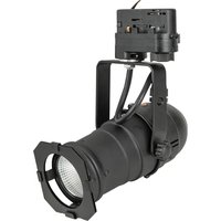
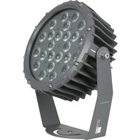
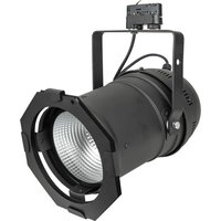
The Arpecta Par 30 Tracklight – Warm on Dim is a compact spot suitable for indoor venues. It features a warm-on-dim technology which mimics the dimming curve of a traditional tungsten lamp. At 100% output the color temperature is 2700 K and at 5% – 1800 K. The high CRI and the lack of UV radiation make it a good solution for clothing shops and galleries. The device is delivered with a color frame.
The device is equipped with a 3-phase track adapter. The 3-phase track adapter is compatible with the Arpecta 3-phase track systems and with the most 3-phase tracks available on the market.
3.1. Front View

01) Track adapter
02) Track lock
03) Circuit selector (OFF, 1, 2 and 3)
07) 2 x Adjustment screws
08) 3 x Color frame holders
09) Color frame
10) Color frame clip
Fig. 02
3.2. Dimensions


Fig. 03
3.3. Product Specifications
| Model: | Par 30 Tracklight – Warm on Dim |
| Electrical: | |
| Input voltage: | 240 V AC, 50/60 Hz |
| Power consumption: | 23 W (at full output) |
| PFC: | 0,96 |
| Physical: | |
| Dimensions: | 224 x 146 x 255 mm (L x W x H) (with the track adapter) |
| Weight: | 0,6 kg (with the track adapter) |
| Track adapter: | |
| Power connection: | 220–250 V, 10 A |
| F max: | 100 N |
| Phases: | 3 |
| Optics: | |
| Light source: | 20 W LED |
| Dimmer: | External, TRIAC type |
| Beam angle: | 45° |
| Luminous flux: | 1100 lm |
| CCT minimum: | 1800 K |
| CCT maximum: | 2700 K |
| CRI: | >95 |
| Construction: | |
| Housing: | Extruded aluminum |
| Color: | Black |
| IP rating: | IP20 |
| Cooling: | Natural convection |
| Thermal: | |
| Maximum ambient temperature t_a : | 40 °C |
| Minimum ambient temperature: | -5 °C |
| Minimum distance: | |
| Minimum distance from flammable surfaces: | 0,5 m |
| Minimum distance to lighted object: | 0,5 m |
4. Installation and Deinstallation
4.1. Safety Instructions

WARNING
Incorrect installation and deinstallation can cause serious injuries and damage of property.
Installation and deinstallation of the device must be carried out only by instructed or skilled persons.
Follow all applicable European, national and local safety regulations concerning electrical installations in buildings and working at heights.
Before installing or deinstalling the device make sure that the track system is disconnected from power supply.
4.2. Personal Protective Equipment
During installation and deinstallation wear personal protective equipment in compliance with the national and site-specific regulations.
4.3. Installation Site Requirements
• The device can be used only indoors.
- The device can be mounted only to a 3-phase track system.
- The minimum distance to other objects must be bigger than 0,5 m.
- The maximum ambient temperature t_ = 40^ must never be exceeded.
• The relative humidity must not exceed 50 % with an ambient temperature of 40 °C
4.4. Mounting
The device can be mounted only to a 3-phase track system.

CAUTION
Restrict the access under the work area during mounting.
To mount the device, follow the steps below:
01) Disconnect the track system from the power supply.
02) Make sure that the circuit selector (03) is in OFF position and the track lock (02) is in unlocked position, as shown in Fig. 04.
03) Align the flange of the track adapter (01) with the track, as shown in Fig. 05.

Fig. 04

Fig. 05
04) Insert the track adapter (01) in the track and push it until it snaps into place.
05) Turn the track lock (02) clockwise to lock the device in the track, as shown in Fig. 07.

natural_image
Technical line drawing of a mechanical assembly with red arrows indicating motion or force directions (no text or symbols present)
natural_image
Technical line drawing of a mechanical assembly with a red arrow indicating rotational motion (no text or symbols)Fig. 06
Fig. 07
06) Select the circuit with the circuit selector (03). You can select 1-, 2- and 3-phase circuit, as shown in Fig. 08.

Attention
Do not slide the track adapter in the track to adjust the position of the device (see Fig. 09). This can damage the connectors. Remove the device from the track and install it at the new place. For more information on how to remove the device from the track, refer to 4.5. Dismounting on page 11.

natural_image
Technical line drawing of a mechanical assembly with a red directional arrow indicating rotational motion (no text or symbols)
natural_image
Technical diagram of a mechanical assembly with red arrows indicating motion or force direction, and a red 'X' symbol in the corner (no text or labels present)Fig. 08
Fig. 09
4.5. Dismounting

CAUTION
Restrict the access under the work area during dismounting.
To dismount the device, follow the steps below:
01) Disconnect the track system from the power supply.
02) Let the device cool down before dismounting.
03) Set the circuit selector (03) in OFF position, as shown in Fig. 10.

Fig. 10
04) Turn the track lock (02) counterclockwise to unlock the device (see Fig. 11).
05) Pull the track adapter (01) from the track (see Fig. 12).

natural_image
Technical line drawing of a mechanical assembly with a red arrow indicating rotation (no text or symbols present)
natural_image
Technical line drawing of a mechanical assembly with red arrows indicating downward motion (no text or symbols)Fig. 11
Fig. 12
4.6. Direction Adjustment
To adjust the angle of the device and the direction of the beam, follow the steps below:
01) Pivot the device around the track adapter (01) to adjust the direction of the beam (see Fig. 13).
02) Turn the 2 adjustment screws (07) counterclockwise to release them.
03) Tilt the device at the desired angle (see Fig. 14).
04) Turn the 2 adjustment screws (07) clockwise to tighten them. Make sure that the device cannot move freely after the 2 adjustment screws (07) are tightened.

natural_image
Technical line drawing of a mechanical component with red directional arrow indicating rotation or movement (no text or symbols)Fig. 13

natural_image
Technical line drawing of a mechanical device with red directional arrows indicating motion or rotation (no text or symbols)Fig. 14
4.7. Color Frame
The Par 30 Tracklight – Warm on Dim is delivered with the color frame installed. You can insert a color gel or a diffusion filter into the color frame. To remove the color frame, follow the steps below:
01) Press the color frame clip (10) and at the same time remove the color frame (09) from the color frame holders (08) (see Fig. 15 and Fig. 16).

natural_image
Technical line drawing of a mechanical device with a red arrow indicating downward motion (no text or symbols present)
natural_image
Technical diagram of a mechanical device with red arrows indicating direction, no text or symbols presentFig. 15
Fig. 16
02) Insert a color gel or a diffusion filter into the color frame.
03) Press the color frame clip (10) and at the same time insert the color frame (09) into the color frame holders (08).
04) Release the color frame clip (10) to lock the color frame in position.
Make sure that the color frame is locked in position with the color frame clip before using the device.
4.8. Connecting to Power Supply
This device is suitable for mounting only to a 3-phase track system. The device is connected to power supply when it is mounted to the track system.
Before installing or deinstalling the device make sure that the track system is disconnected from power supply.
5. Troubleshooting
This troubleshooting guide contains solutions to problems which can be carried out by an ordinary person. The device does not contain user-serviceable parts.
Unauthorized modifications to the device will render the warranty void. Such modifications may result in injuries and material damage.
Refer servicing to instructed or skilled persons. Contact your Highlite International dealer in case the solution is not described in the table.
| Problem | Probable cause(s) | Solution |
| The device does not function | No power to the device | Check if the track system is connected to the power supply |
| Main fuse is blown | Disconnect the device and contact your Highlite International dealer | |
| LEDs are damaged | Disconnect the device and contact your Highlite International dealer | |
| No light or LEDs cut out intermittently | The power supply settings do not match local AC voltage and frequency | Disconnect the device. Check the settings and correct, if necessary |
6. Maintenance
6.1. Safety Instructions for Maintenance
DANGER
Electric shock caused by dangerous voltage inside
Disconnect power supply before servicing or cleaning.
6.2. Preventive Maintenance

Attention
Before use, examine the device visually for any defects.
Make sure that:
- All screws used for installing the device or parts of the device are tightly fastened and are not corroded.
• There are no deformations on housings, fixations and installation points. - The lens is not cracked or damaged.
- The interconnecting power cable is not damaged and does not show any material fatigue.
6.2.1. Basic Cleaning Instructions
The external lens of the device must be cleaned periodically in order to optimize the light output. The cleaning schedule depends on the conditions at the site where the device is installed. When smoke or fog machines are used at the site, the device will need more frequent cleaning. On the other hand, if the device is installed in a well-ventilated area, it will need less frequent cleaning. To establish a cleaning schedule, examine the device at regular intervals during the first 100 hours of operation.
To clean the device, follow the steps below:
01) Disconnect the device from the electrical power supply.
02) Allow the device to cool down for at least 15 minutes.
03) Remove the dust collected on the external surface with dry compressed air and a soft brush.
04) Clean the lens with a damp cloth.
05) Dry the lens carefully with a lint-free cloth.

Attention
- Do not immerse the device in liquid.
- Do not use alcohol or solvents.
6.3. Corrective Maintenance
The device does not contain user-serviceable parts. Do not open the device and do not modify the device.
Refer repairs and servicing to instructed or skilled persons. Contact your Highlite International dealer for more information.
7. Transportation and Storage
7.1. Instructions for Transportation
- Use the original packaging to transport the device, if possible.
- Always observe the handling instructions printed on the outer carton box, for example: "Handle with care", "This side up", "Fragile".
7.2. Storage
- Clean the device before storing. Follow the cleaning instructions in chapter 6.2.1. Basic Cleaning Instructions on pages 13–14.
- Store the device in the original packaging, if possible.
8. Disposal

Correct disposal of this product
Waste Electrical and Electronic Equipment
This symbol on the product, its packaging or documents indicates that the product shall not be treated as household waste. Dispose of this product by handing it to the respective collection point for recycling of electrical and electronic equipment. This is to avoid environmental damage or personal injury due to uncontrolled waste disposal. For more detailed information about recycling of this product contact the local authorities or the authorized dealer.
9. Approval
Check the respective product page on the website of Highlite International (www.highlite.com) for an available declaration of conformity.
- Par 30 Tracklight - Warm on Dim V1
- Preface
- Table of contents
- Introduction......3
- Safety 4
- Description of the Device....7
- Installation and Deinstallation ....9
- Troubleshooting ....13
- Maintenance ....13
- Transportation and Storage....14
- Disposal 14
- Approval....14
- Introduction
- Before Using the Product
- Intended Use
- LEDs Lifespan
- Text Conventions
- Symbols and Signal Words
- Symbols on the Information Label
- Safety
- Warnings and Safety Instructions
- Attention
- Make sure that:
- Requirements for the User
- Description of the Device
- Front View
- Dimensions
- Product Specifications
- Installation and Deinstallation
- Safety Instructions
- Personal Protective Equipment
- Installation Site Requirements
- Mounting
- Dismounting
- Direction Adjustment
- Color Frame
- Connecting to Power Supply
- Troubleshooting
- Maintenance
- Safety Instructions for Maintenance
- Preventive Maintenance
- Basic Cleaning Instructions
- Corrective Maintenance
- Transportation and Storage
- Instructions for Transportation
- Storage
- Disposal
- Correct disposal of this product
- Approval
Brand : Artecta
Model : Par 30 Tracklight - Warm on Dim
Category : Lighting