
1960 - Compressor DRAWMER - Free user manual and instructions
Find the device manual for free 1960 DRAWMER in PDF.


| Product Type | Dual Vacuum Tube Compressor with Microphone Pre-amplifier and Instrument Input |
| Form Factor | 19-inch rack mount, 2U |
| Weight (including packaging) | 6.0 kg |
| Power Requirements | 230V or 115V AC, 50-60Hz, 38W |
| Mains Fuse Rating (230V) | 250mA, time-delay, 20mm x 5mm, IEC 127-2 |
| Mains Fuse Rating (115V) | 500mA, time-delay, 20mm x 5mm, IEC 127-2 |
| HT Fuse Rating | 50mA (both voltage settings) |
| Input Impedances | Line: 20kΩ, Mic: 150Ω to 600Ω, Aux: 2.2MΩ |
| Maximum Input Level | +20dBu |
| Output Impedance | 50Ω |
| Maximum Output Level | +22dBm (balanced) |
| Frequency Response | <10Hz to 22kHz (-1dB) |
| Mic Input Noise | -128.5dB (at +60dB gain) |
| Distortion (THD+N, 1kHz, Normal) | <0.3% |
| Compressor Type | Soft-knee, dual-stage tubes in signal path |
| Compressor Controls | Threshold (-24dB to off), Attack (Fast/Med/Slow), Release (1-4 fixed, 5-6 program dependent), Output Gain (±20dB) |
| Microphone Preamp Gain | 0 to 60dB, with clip LED |
| Auxiliary Input Features | 2.2MΩ impedance, passive Bass and Treble EQ, Bright switch (2kHz boost), Low/High gain switch, Flat/EQ bypass |
| Stereo Link | Yes, averages control settings between channels |
| Meters | Dual moving-coil VU, switchable between output level and gain reduction |
| Safety | Do not expose to rain/moisture; refer servicing to qualified personnel; replace fuses only with specified type |
| Warranty | One year limited warranty from original purchase date |
Frequently Asked Questions - 1960 DRAWMER
User questions about 1960 DRAWMER
0 question about this device. Answer the ones you know or ask your own.
Ask a new question about this device
Download the instructions for your Compressor in PDF format for free! Find your manual 1960 - DRAWMER and take your electronic device back in hand. On this page are published all the documents necessary for the use of your device. 1960 by DRAWMER.
USER MANUAL 1960 DRAWMER
SAFETY CONSIDERATIONS page 1
INTRODUCTION page 2
APPLICATIONS page 2
INSTALLATION page 3
CONTROL DESCRIPTIONS: page 5
○ Compressor page 5
○ Microphone Pre-amplifier page 7
○ Auxiliary Input page 7
QUICK SET-UP page 8
IF A FAULT DEVELOPS page 9
CONTACTING DRAWMER page 9
TECHNICAL SPECIFICATION
BLOCK DIAGRAM
page 10
page 11
COPYRIGHT
This manual is copyrighted © 1993 by Drawmer Electronics, Ltd. With all rights reserved. Under copyright laws, this manual may not be duplicated in whole or in part without the written consent of Drawmer.
ONE YEAR LIMITED WARRANTY
Drawmer Electronics Ltd., warrants the Drawmer 1960 audio processor to conform substantially to the specifications of this manual for a period of one year from the original date of purchase when used in accordance with the specifications detailed in this manual. In the case of a valid warranty claim, your sole and exclusive remedy and Drawmer's entire liability under any theory of liability will be to, at Drawmer's discretion, repair or replace the product without charge, or, if not possible, to refund the purchase price to you. This warranty is not transferable. It applies only to the original purchaser of the product.
For warranty service please call your local Drawmer dealer. Alternatively call Drawmer Electronics Ltd. at +44 (0)1709 527574. Then ship the defective product, with transportation and insurance charges pre-paid, to Drawmer Electronics Ltd., Coleman Street, Parkgate, Rotherham, S62 6EL UK. Write the RA number in large letters in a prominent position on the shipping box. Enclose your name, address, telephone number, copy of the original sales invoice and a detailed description of the problem. Drawmer will not accept responsibility for loss or damage during transit.
This warranty is void if the product has been damaged by misuse, modification or unauthorised repair.
THIS WARRANTY IS IN LIEU OF ALL WARRANTIES, WHETHER ORAL OR WRITTEN, EXPRESSED, IMPLIED OR STATUTORY. DRAWMER MAKES NO OTHER WARRANTY EITHER EXPRESS OR IMPLIED, INCLUDING, WITHOUT LIMITATION, ANY IMPLIED WARRANTIES OF MERCHANTABILITY, FITNESS FOR A PARTICULAR PURPOSE, OR NON-INFRINGEMENT. PURCHASER'S SOLE AND EXCLUSIVE REMEDY UNDER THIS WARRANTY SHALL BE REPAIR OR REPLACEMENT AS SPECIFIED HEREIN.
IN NO EVENT WILL DRAWMER ELECTRONICS LTD. BE LIABLE FOR ANY DIRECT, INDIRECT, SPECIAL, INCIDENTAL OR CONSEQUENTIAL DAMAGES RESULTING FROM ANY DEFECT IN THE PRODUCT, INCLUDING LOST PROFITS, DAMAGE TO PROPERTY, AND, TO THE EXTENT PERMITTED BY LAW, DAMAGE FOR PERSONAL INJURY, EVEN IF DRAWMER HAS BEEN ADVISED OF THE POSSIBILITY OF SUCH DAMAGES.
Some states and specific countries do not allow the exclusion of implied warranties or limitations on how long an implied warranty may last, so the above limitations may not apply to you. This warranty gives you specific legal rights. You may have additional rights that vary from state to state, and country to country.
In the interests of product development, Drawmer reserve the right to modify or improve specifications of this product at any time, without prior notice.
DRAWMER 1960 Dual Vacuum Tube Compressor

SAFETY CONSIDERATIONS

CAUTION - MAINS FUSE
TO REDUCE THE RISK OF FIRE REPLACE THE MAINS FUSE ONLY WITH A FUSE THAT CONFORMS TO IEC 127-2. 250 VOLT WORKING, TIME DELAY TYPE WITH A BODY SIZE OF 20mm x 5mm.
THE MAINS INPUT FUSE MUST BE RATED AT 250mA WHERE THE MAINS INPUT VOLTAGE SWITCH IS SET TO 230 VOLTS AC. AND 500mA WHERE THE MAINS INPUT VOLTAGE IS 115 VOLTS AC.
THE REAR PANEL H.T. FUSE MUST ALWAYS BE RATED AT 50mA, IRRESPECTIVE OF THE MAINS VOLTAGE SETTING.
CAUTION - MAINS CABLE
DO NOT ATTEMPT TO CHANGE OR TAMPER WITH THE SUPPLIED MAINS CABLE.
CAUTION - SERVICING
DO NOT PERFORM ANY SERVICING. REFER ALL SERVICING TO QUALIFIED SERVICE PERSONNEL.
WARNING
TO REDUCE THE RISK OF FIRE OR ELECTRIC SHOCK DO NOT EXPOSE THIS EQUIPMENT TO RAIN OR MOISTURE.

CAUTION
RISK OF ELECTRIC SHOCK DO NOT OPEN

INTRODUCTION
The 1960 is a hybrid vacuum tube/semi-conductor, dual-channel compressor which has numerous applications in studio recording, live sound, location recording, post-production and as part of a musician's rack system.
The microphone input stages feature extremely low noise, balanced input circuitry with additional tube amplification, enabling modern microphones to take on the characteristics of older tube models.
A versatile instrument pre-amplifier with passive EQ and brightness switch, which may be routed through both compressor channels.
Suitable for a variety of signal sources, from electric guitars and basses to electronic keyboards, and is designed to be deliberately overdriven to add tonal colouration to an instrument.

Two low-noise microphone preamplifiers with provision for phantom powering.
Compressor section provides soft-knee compression, with four, dual-stage tubes in the signal path.
Switchable Attack, and switchable Release with two programme dependent settings.
Traditional moving coil meters monitor either gain reduction or output signal level.
An output gain control provides up to 20dB of make-up gain.
APPLICATIONS
- General studio compressor
○ Complete stereo mixes. - For high quality location recording, the 1960 makes the perfect partner for a DAT machine, as it combines the functions of stereo mic preamp with that of a compressor.
- The mic inputs provide up to 60dB of gain.
- As an instrument amplifier, the 1960 provides gain, EQ and compression, providing the type of overdrive sound associated with tube guitar amplifiers.
When the compressor is overdriven, it can be used creatively on electric guitar or rock vocal sounds.
The Aux input may be used for processing the output from a dedicated guitar preamplifier, where the EQ can be used to further tailor the sound before it is compressed.
INSTALLATION
The 1960 is designed for standard 19" rack mounting and occupies 2U of rack space. Avoid mounting the unit directly above power amplifiers or power supplies that radiate significant amounts of heat and always connect the mains earth to the unit. Fibre or plastic washers may be used to prevent the front panel becoming marked by the mounting bolts. Because the tube circuitry generates more heat than an equivalent solid-state design, it is advisable to leave space above the unit to allow the heat to dissipate.
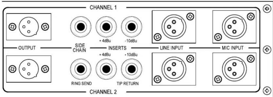
AUDIO CONNECTIONS
The inputs and outputs are electronically balanced on conventionally wired XLRs (pin 1 screen, pin 2 hot, pin 3 cold and XLR shell is connected to chassis). The 1960 fully conforms to the EMC standards, if the unit is used where it may be exposed to high levels of disturbance such as found close to a TV or radio transmitter we suggest that the screen of the signal cable is connected to the chassis connection on the XLR type connector. The operating level is nominally +4dBu.
If earth loop problems are encountered, do not disconnect the mains earth but instead, try disconnecting the signal screen on one end of the cables connecting the outputs of the 1960 to the patchbay. Balanced operation is recommended.
The side-chain access point and the two different level insert points are unbalanced. The side chain feature on the 1960 is part of the compressor feedback stage and would normally be connected to a normalised or semi-normalised pair of patchbay contacts. This would allow the user to insert additional EQ for some de-essing, or frequency conscious compression. The intended use of the audio insert jacks would be to patch in EQ (eg 1961), reverb or similar processing. Connection is via stereo 14 " jacks, the wiring convention being: ring is signal send, tip is signal return and sleeve ground.
POWER CONNECTION
The unit will have been supplied with a power cable suitable for domestic power outlets in your country. For your own safety it is important that you use this cable. The unit should always be connected to the mains supply earth using this cable.
If for some reason the unit is to be used at a mains input operating voltage which is different to that as supplied, the following procedure must be carried out. (see following diagram)
1: Disconnect the unit from the mains.
2: With a size1 pozidrive screwdriver, remove the two self-tapping screws holding the voltage selection switch cover plate on the rear panel.
3: Remove the cover plate and slide the switch fully to its opposite end.
4: Rotate the cover plate one half turn, (180°) and refit the two screws.
5: Fit a correctly rated Mains Fuse for the selected operation voltage. Do not make any changes to the HT Fuse.
6: Re-connect to mains power source.

CONTROL DESCRIPTION AND OPERATION
With the exception of the Aux preamp section, both channels of the 1960 are identical and may be used independently or linked for stereo operation. In linked mode, the compressor controls should, ideally, be set to the same settings (as the control-circuitry for both channels responds to the average between the two channel settings). In Stereo Link mode, both channels track together to avoid the inevitable image shifting that would occur if the two channels of a stereo signal were treated independently.
COMPRESSOR
Source Select: This rotary switch selects the compressor input source. The
Line and Mic inputs are via the rear-panel XLRs while the Aux input is available on the front panel. The two Mic positions offer an input with or without +48V phantom powering, with a red LED lit when active.
Note: if the Aux input is to be used at the same time as a Mic input, it is recommended that the Mic input be processed through the upper channel and the Aux input through the lower channel as this minimises crosstalk between tube amplification stages sharing the same envelope.
High-pass: The signal path incorporates a switchable high-pass filter
which may be set to 50Hz, 100Hz or Off. Its use is to attenuate low frequency signals that might otherwise prove troublesome, eg. traffic rumble or stage vibration.
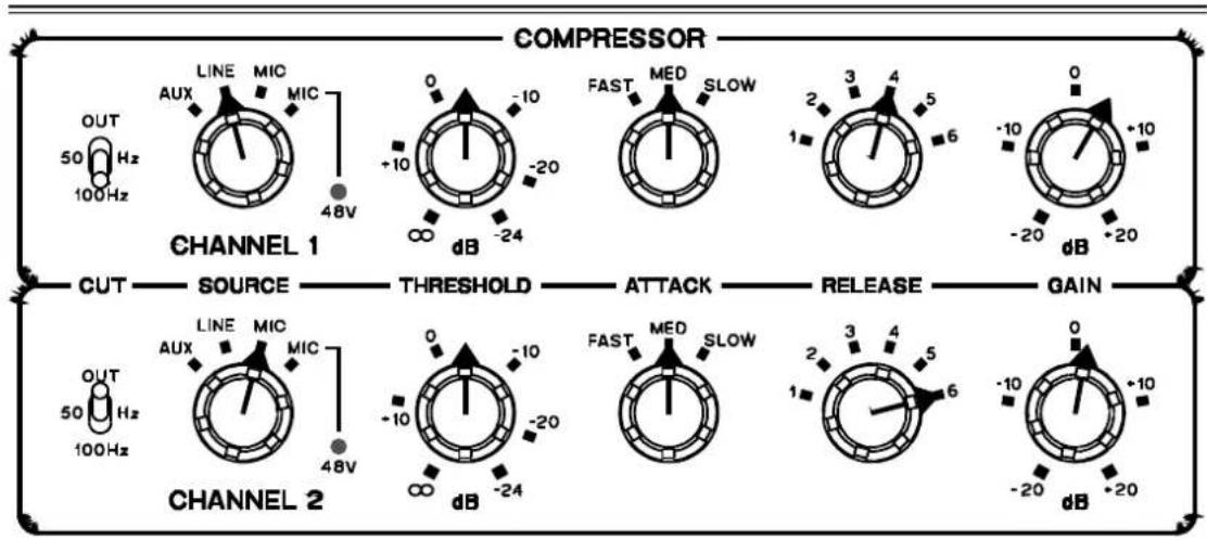
Threshold: Determines the input level above which gain reduction will
be applied and may be set in the range -24dB to infinity. Because the compression system is based on the Soft Knee principle, the onset of compression is progressive, so no Ratio control is necessary.
Attack: Three switchable. Attack settings are provided giving Fast,
Medium and Slow attack times. The actual attack time is further modified by the release setting chosen.
Release:

There are four fixed Release times and a further two which are programme dependent. Switch settings 1 through to 4 provide progressively increasing release times, while positions 5 and 6 cause the release times to vary in a manner which automatically adapts to the dynamics of the incoming signal, as detailed below:-
Release Times 1 400 ms (Fixed)
2 1 sec (Fixed)
3 2 sec (Fixed)
4 4 sec (Fixed)
5 Automatic 400 ms to 2 sec signal dependent
6 Automatic 200 ms to 20 sec signal dependent
Output: (Gain)

The Output level may be amplified, or attenuated by up to 20dB to compensate for level changes caused by compression and limiting.
VU Meter:

A moving coil VU meter monitors either the level of the output signal (over the range -10dB to +10dB with reference to the +4dBu operating level) or the amount of gain reduction taking place. Because the meter has VU characteristics, it closely reflects what is actually being heard, though will not respond quickly enough to register short signal peaks.
VU / GR:

Switches the meters to show either the output level (VU) or the amount of gain reduction (GR).
Norm/Bypass
S/C Listen:

In Normal mode, the signal is passed through the compressor. Bypass only takes the compressor out of circuit leaving the vacuum tube warmth in the circuit path; the output signal is taken from the signal insert return point. S/C Listen routes the side-chain signal directly to the output allowing the effects of any additional side-chain processing, such as equalisation, to be monitored.

Stereo Link: Averages the left and right channel control settings
when the unit is used for processing a stereo signal. The same degree of gain reduction is applied to both audio channels to prevent image shifting which would otherwise occur whenever the left and right signal dynamics varied from each other by any significant degree.
MICROPHONE PRE-AMPLIFIER
Mic Input Gain: This fully variable control sets the mic input gain over the range 0 to 60dB. The adjacent Clip LED illuminates when excessive Mic gain has been applied and there is a danger of clipping.
AUXILIARY INPUT
The Auxiliary Input has a 2M2Ω impedance and feeds a specialised instrument input stage which provides both gain and equalisation, suitable for use with both active and passive guitar pickup systems as well as with electronic keyboards. The passive Bass and Treble controls are based on those used in classic tube guitar amplifiers while the Bright switch puts a peak in the frequency response at around 2kHz to simulate the voicing of a typical guitar amplifier. A two position high or low gain switch provides an additional 10dB of gain when required for level matching or for creating overdrive effects.
When setting up a good starting point is to switch Bright 'On' and set the compressor for 'Med' attack and '6' release. The threshold should be adjusted to give a gain reduction reading of around 5dB on signal peaks. By increasing the Gain control setting, the input stage can be made to overdrive in a manner similar to that of traditional valve guitar amplifiers.

Bass EQ: Passive equanser control, which can be set to provide up to 15dB of bass boost at 40Hz.
Treble EQ: Passive equaliser control, which can be set to provide up to 18dB of treble boost at 16kHz.
Gain: Provides up to 30dB of gain at the Low Gain switch setting or 40dB at the High Gain setting.
Low/High: Sensitivity selector switch. Adds 10dB of gain in the High position.
Flat/EQ: Switches the equaliser controls out of circuit when a flat response is required, or for 'A/B' comparison of EQ effectiveness.
Norm/Bright: Switches in 10dB of boost at 2kHz in the Bright position, (when 'EQ' has been selected on the Flat/EQ switch.)
QUICK SET UP
○ Select Stereo Link mode for use with a stereo signal, otherwise ensure this switch is Off.
○ Choose correct signal source for each channel using selector.
Initially, set the Attack selector to the Medium position and set Release to 6 (Programme Dependent).
- Set the Mode switch to Normal and the Meter switch to GR.
With programme material playing, adjust the Threshold control until the desired amount of gain reduction registers on the meters.
- Use the Output Gain control to restore any level lost due to compression.
- If necessary, change the Attack and Release settings to suit the material.
IF A FAULT DEVELOPS
For warranty service please call Drawmer Electronics Ltd. Or their nearest authorised service facility, giving full details of the difficulty. On receipt of this information, service or shipping instructions will be forwarded to you. No equipment should be returned under the warranty without prior consent from Drawmer or their authorised representative.
For service claims under the warranty agreement a service Returns Authorisation (RA) number will be given. Write this RA number in large letters in a prominent position on the shipping box. Enclose your name, address, telephone number, copy of the original sales invoice and a detailed description of the problem.
Authorised returns should be prepaid and must be insured. All Drawmer products are packaged in specially designed containers for protection. If the unit is to be returned, the original container must be used. If this container is not available, then the equipment should be packaged in substantial shock-proof material, capable of withstanding the handling for the transit.
CONTACTING DRAWMER
Drawmer Electronics Ltd., will be pleased to answer all application questions to enhance your usage of this equipment. Please address correspondence to:
Drawmer (Technical Help line) : Coleman St.: Parkgate : Rotherham : S62 6EL : UK
or, E-mail us on : tech@drawmer.com
Drawmer dealers, Authorised service departments and other contact information can be obtained from our web pages on http://www.drawmer.com
TECHNICAL SPECIFICATIONS
(All measurements taken at +4dBu operating level)
INPUT IMPEDANCES LINE 20KΩ
MIC 150Ω to 600Ω
AUX 2M2Ω
MIC INPUT NOISE -128.5dB (@ +60dB gain)
MAXIMUM INPUT LEVEL +20dBu
OUTPUT IMPEDANCE 50 Ω
MAXIMUM OUTPUT LEVEL +22dBm (balanced)
BANDWIDTH <10Hz to 22KHz -1dB
COMPRESSOR NOISE AT UNITY GAIN
| Wideband 22Hz - 22KHz CCIR ARM IEC A Q-Pk CCIR | |||||
| AV | -82dB | -88dB | -88dB | -91dB | -77dB |
| RMS | -81dB | -87dB | -87dB | -90dB | |
| DISTORTION (THD & Noise) | 1KHz |
| Line Input with BYPASS selected | < 0.1% |
| Line Input with NORMAL selected | < 0.3% |
POWER REQUIREMENTS
230Volt or 115Volt at 50-60Hz,
38 Watts
FUSE RATING
250mA for 230Volt,
500mA for 115Volt
CONFORMING TO IEC 127-2
FUSE TYPE
20mm x 5mm, Class 3 Slo-Blo, 250Volt working
CASE SIZE
WEIGHT (incl packaging)
6.0 Kgs
BLOCK DIAGRAM

flowchart
graph TD
    subgraph CHANNEL 1
        A["MC INPUT"] --> B["MCC THE AMP STATE"]
        B --> C["CLIP"]
        C --> D["LINE INPUT STATE"]
        D --> E["INPUT SOURCE SELECTOR SWITCH"]
        E --> F["HOM PASS FILTER"]
        F --> G["VALUE STATE"]
        G --> H["VCA INCLUDING 2 VALUE STAGES"]
        H --> I["OUTPUT GAIN"]
        I --> J["BALANCED OUTPUT DRIVER"]
        J --> K["AUDIO OUTPUT"]
        L["AUX INPUT"] --> M["AUX INPUT STATE"]
        M --> N["AUX EU & CADI"]
        N --> O["AUX INPUT DUAL VALUE STATE"]
        O --> P["SIDE CHAIN"]
        P --> Q["THRESHOLD"]
        Q --> R["ATTACK"]
        R --> S["RELEASE"]
        S --> T["VU / OR METERS"]
        U["AUX INPUT"] --> V["AUX INPUT STATE"]
        V --> W["AUX EU & CADI"]
        W --> X["AUX INPUT DUAL VALUE STATE"]
        X --> Y["SIDE CHAIN"]
        Y --> Z["INPUT SOURCE SELECTOR SWITCH"]
        Z --> AA["HOM PASS FILTER"]
        AA --> AB["VALUE STATE"]
        AB --> AC["VCA INCLUDING 2 VALUE STAGES"]
        AC --> AD["OUTPUT GAIN"]
        AD --> AE["BALANCED OUTPUT DRIVER"]
        AE --> AF["AUDIO OUTPUT"]
    end

    subgraph CHANNEL 2
        AG["MC INPUT"] --> AH["MCC THE AMP STATE"]
        AH --> AI["CLIP"]
        AI --> AJ["LINE INPUT STATE"]
        AJ --> AK["SIDE CHAIN"]
        AK --> AL["THRESHOLD"]
        AL --> AM["ATTACK"]
        AM --> AN["RELEASE"]
        AN --> AO["VU / OR METERS"]
        AP["AUX INPUT"] --> AQ["AVA INPUT STATE"]
        AQ --> AR["AUX EU & CADI"]
        AR --> AS["AUX INPUT DUAL VALUE STATE"]
        AS --> AT["SIDE CHAIN"]
        AT --> AU["INPUT SOURCE SELECTOR SWITCH"]
        AU --> AV["HOM PASS FILTER"]
        AV --> AW["VALUE STATE"]
        AW --> AX["VCA INCLUDING 2 VALUE STAGES"]
        AX --> AY["OUTPUT GAIN"]
        AY --> AZ["BALANCED OUTPUT DRIVER"]
        AZ --> BA["AUDIO OUTPUT"]
    end

    style CHANNEL 1 fill:#f9f,stroke:#333
    style CHANNEL 2 fill:#f9f,stroke:#333
- COPYRIGHT
- ONE YEAR LIMITED WARRANTY
- DRAWMER 1960 Dual Vacuum Tube Compressor
- CAUTION - MAINS FUSE
- CAUTION - MAINS CABLE
- CAUTION - SERVICING
- WARNING
- INTRODUCTION
- APPLICATIONS
- INSTALLATION
- AUDIO CONNECTIONS
- POWER CONNECTION
- CONTROL DESCRIPTION AND OPERATION
- COMPRESSOR
- Release:
- Output: (Gain)
- VU Meter:
- VU / GR:
- Norm/Bypass
- S/C Listen:
- MICROPHONE PRE-AMPLIFIER
- AUXILIARY INPUT
- QUICK SET UP
- IF A FAULT DEVELOPS
- CONTACTING DRAWMER
- TECHNICAL SPECIFICATIONS
- POWER REQUIREMENTS
- FUSE RATING
- FUSE TYPE
- CASE SIZE
- WEIGHT (incl packaging)
Brand : DRAWMER
Model : 1960
Category : Compressor