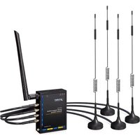
ICG-2210W-NR - Network router Planet - Free user manual and instructions
Find the device manual for free ICG-2210W-NR Planet in PDF.


| Product Type | Industrial 5G NR Compact Cellular Wireless Gateway |
| Model | ICG-2210W-NR |
| Brand | Planet |
| Dimensions (W x D x H) | 76 x 23.5 x 106 mm |
| Weight | 285 g |
| Power Input | 9~36 V DC, 14.4 W max |
| Operating Temperature | -40°C to 75°C |
| Ethernet Ports | 2 x 10/100/1000BASE-T RJ45 (1 WAN/LAN, 1 LAN) |
| Cellular Support | 5G NR (NSA/SA), LTE FDD/TDD, WCDMA; DL up to 2.4 Gbps |
| SIM Slots | 2 x micro SIM with failover |
| Wireless Standard | IEEE 802.11a/b/g/n/ac, dual-band 2.4 GHz & 5 GHz |
| Wireless Speed | Up to 150 Mbps (2.4 GHz) + 433 Mbps (5 GHz) |
| VPN Protocols | IPSec, PPTP, L2TP, OpenVPN, GRE; up to 30 tunnels |
| Firewall | SPI, DoS/DDoS protection, content filtering |
| Serial Ports | 1 x RS232, 1 x RS485 |
| Management | Web (HTTP/HTTPS), SNMP v1/v2c/v3, SSHv2, Telnet, Planet Smart Discovery Utility |
| Mounting | DIN-rail, wall-mount (kit included) |
| Enclosure | IP30 metal case |
| Antennas | 4 x 5G NR (5 dBi SMA), 1 x Wi-Fi (2 dBi) |
| LED Indicators | PWR, SYS, Internet (5G/4G), Wi-Fi, LAN LNK/ACT |
| Regulatory Compliance | CE, FCC |
Frequently Asked Questions - ICG-2210W-NR Planet
User questions about ICG-2210W-NR Planet
0 question about this device. Answer the ones you know or ask your own.
Ask a new question about this device
Download the instructions for your Network router in PDF format for free! Find your manual ICG-2210W-NR - Planet and take your electronic device back in hand. On this page are published all the documents necessary for the use of your device. ICG-2210W-NR by Planet.
USER MANUAL ICG-2210W-NR Planet
User's Manual
Industrial 5G NR Compact Cellular Wireless Gateway
ICG-2210W-NR

Copyright
Copyright (C) 2025 PLANET Technology Corp. All rights reserved.
The products and programs described in this User's Manual are licensed products of PLANET Technology, This User's Manual contains proprietary information protected by copyright, and this User's Manual and all accompanying hardware, software, and documentation are copyrighted.
No part of this User's Manual may be copied, photocopied, reproduced, translated, or reduced to any electronic medium or machine-readable form by any means, electronic or mechanical including photocopying, recording, or information storage and retrieval systems, for any purpose other than the purchaser's personal use, and without the prior express written permission of PLANET Technology.
Disclaimer
PLANET Technology does not warrant that the hardware will work properly in all environments and applications, and makes no warranty and representation, either implied or expressed, with respect to the quality, performance, merchantability, or fitness for a particular purpose.
PLANET has made every effort to ensure that this User's Manual is accurate; PLANET disclaims liability for any inaccuracies or omissions that may have occurred. Information in this User's Manual is subject to change without notice and does not represent a commitment on the part of PLANET. PLANET assumes no responsibility for any inaccuracies that may be contained in this User's Manual. PLANET makes no commitment to update or keep current the information in this User's Manual, and reserves the right to make improvements and/or changes to this User's Manual at any time without notice.
If you find information in this manual that is incorrect, misleading, or incomplete, we would appreciate your comments and suggestions.
FCC Radiation Exposure Statement
This equipment complies with FCC RF radiation exposure limits set forth for an uncontrolled environment. This equipment should be installed and operated with a minimum distance of 20 centimeters between the radiator and your body.
This transmitter must not be co-located or operating in conjunction with any other antenna or transmitter. The antennas used for this transmitter must be installed to provide a separation distance of at least 20 cm from all persons and must not be co-located or operating in conjunction with any other antenna or transmitter.
FCC Caution:
To assure continued compliance, for example, use only shielded interface cables when connecting to computer or peripheral devices. Any changes or modifications not expressly approved by the party responsible for compliance could void the user's authority to operate the equipment.
This device complies with Part 15 of the FCC Rules. Operation is subject to the following two conditions:
(1) This device may not cause harmful interference
(2) This device must accept any interference received, including interference that may cause undesired operation.
CE Compliance Statement
This device meets the RED directive 2014/53/EU of EU requirements on the limitation of exposure of the general public to electromagnetic fields by way of health protection.
The device complies with RF specifications when the device used at 20 cm from your body.
Safety
This equipment is designed with the utmost care for the safety of those who install and use it. However, special attention must be paid to the dangers of electric shock and static electricity when working with electrical equipment. All guidelines of this and of the computer manufacture must therefore be allowed at all times to ensure the safe use of the equipment.
WEEE

To avoid the potential effects on the environment and human health as a result of the presence of hazardous substances in electrical and electronic equipment, end users of electrical and electronic equipment should understand the meaning of the crossed-out
wheeled bin symbol. Do not dispose of WEEE as unsorted municipal waste and have to collect such WEEE separately.
Trademarks
The PLANET logo is a trademark of PLANET Technology. This documentation may refer to numerous hardware and software products by their trade names. In most, if not all cases, these designations are claimed as trademarks or registered trademarks by their respective companies.
Revision
User's Manual of PLANET Industrial 5G NR Compact Cellular Wireless Gateway
Model: ICG-2210W-NR
Rev.: 1.1 (March, 2025)
Part No. EM-ICG-2210W-NR_v1.1
Table of Contents
Chapter 1. Product Introduction......6
1.1 Package Contents....6
1.2 Overview....7
1.3 Features....10
1.4 Product Specifications ....12
Chapter 2. Hardware Introduction ......15
2.1 Physical Descriptions....15
2.2 Hardware Installation ....16
2.2.1 SIM Card Installation....16
2.2.2 5G NR and Wi-Fi Antenna Installation....17
2.2.3 Wiring the Power Inputs....18
2.2.4 Grounding the Device ....18
Chapter 3. Preparation ....19
3.1 Requirements....19
3.2 Setting TCP/IP on your PC 20
3.3 Planet Smart Discovery Utility....25
Chapter 4. Web-based Management....27
4.1 Introduction ......27
4.2 Logging in to the Cellular Gateway....27
4.3 Main Web Page....29
4.4 Setup....30
4.4.1 Basic Setup....30
4.4.1.1 WAN Setup 30
4.4.1.2 Network Setup 35
4.4.2 DDNS 38
4.4.3 MAC Address Clone 39
4.4.4 Advanced Routing ....40
4.4.5 VLANs....42
4.4.6 Networking....43
4.4.6.1 Bridging....43
4.4.6.2 Port Setup 45
4.4.6.3 DHCPD 46
4.5 Wireless 47
4.5.1 Basic Setting....47
4.5.2 Wireless Security....50
4.6 Services 52
4.7 VPN....57
4.7.1 PPTP....57
4.7.2 L2TP 60
4.7.3 OPENVPN 63
4.7.4 IPSEC 69
4.7.5 GRE 73
4.8 Security 75
4.8.1 Firewall....75
4.9 Access Restrictions....79
4.9.1 WAN Access 79
4.9.2 MAC Filtering 81
4.9.3 Packet Filtering....83
4.10 NAT 84
4.10.1 Port Forwarding 84
4.10.2 Port Range Forwarding....85
4.10.3 DMZ 86
4.11 QoS Setting....87
4.11.1 Basic 87
4.11.2 Classify 89
4.12 Applications....90
4.12.1 Serial Applications 90
4.13 Administration 93
4.13.1 Management....93
4.13.2 Keep Alive 96
4.13.3 Commands....97
4.13.4 Factory Defaults....98
4.13.5 Firmware Upgrade....99
4.13.6 Backup....100
4.14 Status....101
4.14.1 Router 101
4.14.2 WAN....104
4.14.3 LAN....107
4.14.4 Wireless....109
4.14.5 Bandwidth 112
4.14.6 Sys Info....114
Appendix A: DDNS Application 118
Chapter 1. Product Introduction
Thank you for purchasing PLANET Industrial 5G NR Compact Cellular Wireless Gateway, ICG-2210W-NR. The description of this model is as follows:
| Model Name | Description |
| ICG-2210W-NR | Compact Industrial 5G NR Cellular Wireless Gateway with 2-Port 10/100/1000T |
"Cellular Gateway" mentioned in the manual refers to the above model.
1.1 Package Contents
The package should contain the following:
| Cellular Gateway x 1 | QR Code Sheet | 5G NR Antenna x 4 | |
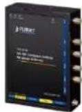 |  |  | |
| Wi-Fi Antenna x 1 | DIN-rail Mounting Kit | 6-pin Terminal Block x 1 | |
| [XTH4] |  |  | |
| DB9 to 3 pins (2 3 5) | DC Adapter | RJ45 Dust Cap x 2 | |
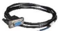 |  |  | |
| RJ45 UTP Ethernet Cable x 1 | Wall Mounting Kit | ||
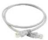 |  | ||
 Note Note | If any of the above items are missing, please contact your dealer immediately. | ||
Note
1.2 Overview
Powerful 5G NR and Wi-Fi 5 Industrial Network Solution
PLANET ICG-2210W-NR is an industrial-grade wireless cellular gateway for demanding mobile applications. Packed with cutting-edge features, including 5G NR (new radio) technology, dual WAN, and two micro SIM slots, it goes further with dual high-speed Gigabit Ethernet LAN ports and WAN/LAN ports, 802.11ac Wi-Fi capability, and serial RS232/RS485 communication interface. With a compact design, the ICG-2210W-NR is perfect for confined spaces or vehicular applications. The addition of ICG-2210W-NR failover ensures uninterrupted connectivity in dynamic environments. Tailored for versatility, it excels in harsh industrial environments and vehicular systems. Whether in tight quarters, mobile setups, or challenging industrial settings, the ICG-2210W-NR gateway ensures seamless and reliable connectivity. Its adaptability, coupled with advanced features, makes it the ideal solution for compact spaces and demanding applications.

Automatic Failover between 5G NR and Gigabit WAN
The ICG-2210W-NR boasts Gigabyte Ethernet wired WAN and 5G NR interfaces with seamless failover capabilities, ensuring continuous Internet access. It provides the flexibility to prioritize between 5G NR and wired WAN connections. In case of a primary WAN interface failure, the secondary interface swiftly restores the connection, ensuring uninterrupted connectivity at all times.
![graph LR A["Internet"] -->|Cable| B["5G NR"] B --> C["Failover"] C --> D["Industrial 5G NR Cellular Gateway"] style A fill:#f9f,stroke:#333 style B fill:#ccf,stroke:#333 style C fill:#cfc,stroke:#333 style D fill:#fcc,stroke:#333](/content/2026/05/900931/images/98bad3611040af2bd4639cf2476b62eb2f51d74bca28494d7b82db2b3f28be64.jpg)
Ultra-Fast Speed 4G/5G Network
The ICG-2210W-NR supports 5G NR DL speed of 2.4 Gbps faster than 4G LTE DL speed of 1 Gbps. The wide spectrum bandwidth accelerates internet speeds and reduces network latency for premium and time-sensitive connectivity services. The ICG-2210W-NR also supports multi-band connectivity including LTE FDD/TDD, WCDMA and GSM for a wide range of applications.
*The real 5G NR/4G LTE data rate is dependent on local service provider.
Up to download speed 2.4 Gbps

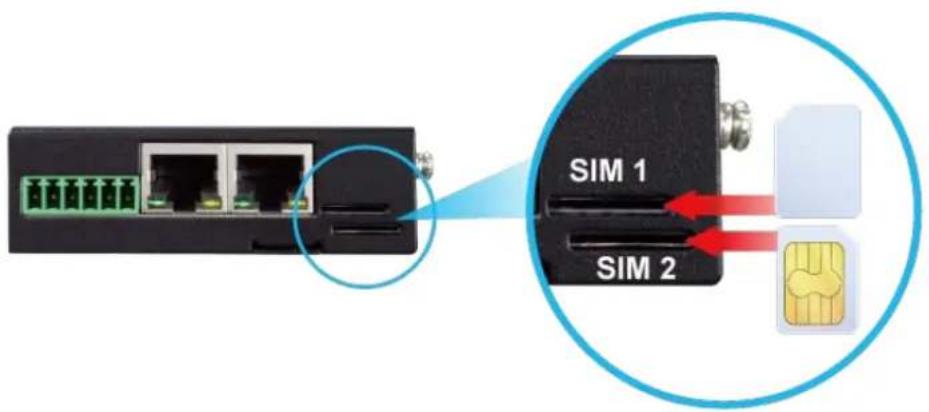
Dual SIM Design
To enhance reliability, the ICG-2210W-NR is equipped with dual micro SIM slots that support failover and roaming over to ensure uninterrupted connectivity for mission-critical cellular communications. It provides a more flexible and easier way for users to create an instant network sharing service via 5G-NR in public places like transportations, outdoor events, etc.
Ideal High-Availability VPN Security Cellular Gateway Solution for Industrial Environment
The ICG-2210W-NR provides complete data security and privacy for accessing and exchanging the most sensitive data, built-in IPSec VPN function with DES/3DES/AES encryption and MD5/SHA-1/SHA-256/SHA-384/SHA-512 authentication, and GRE, SSL, PPTP and L2TP server mechanism. The full VPN capability in the ICG-2210W-NR makes the connection secure, more flexible, and more capable.
![graph LR A["Industrial 5G NR Cellular Gateway"] --> B["Failover Connection"] B --> C["Content Filtering"] C --> D["VPN Tunnel"] D --> E["Factory Building"]](/content/2026/05/900931/images/7a557e973815267592833e009cdf7f126fef0c0ae5b7df7ac716cbc937467cfa.jpg)
Wireless 11ac Brings Excellent Data Link Speed
PLANET ICG-2210W-NR, adopting the IEEE 802.11ac Wave 2 standard, provides a high-speed transmission of power and data, meaning two remote nodes in the 5GHz frequency band can be bridged.
The 2.4GHz wireless connection can also be used simultaneously.
Excellent Ability in Threat Defense
The ICG-2210W-NR has built-in SPI (stateful packet inspection) firewall and DoS/DDoS attack mitigation functions to provide high efficiency and extensive protection for your network. Thus, virtual server and DMZ functions can let you set up servers in the Intranet and still provide services to the Internet users.
![graph LR A["DoS/DDoS Attack"] --> B["Blocking DoS Attack"] B --> C["Industrial Cellular Gateway"] C --> D["Ethernet Switch"] D --> E["1000BASE-T UTP"] style A fill:#f9f,stroke:#333 style B fill:#ccf,stroke:#333 style C fill:#cfc,stroke:#333 style D fill:#fcc,stroke:#333 style E fill:#cff,stroke:#333](/content/2026/05/900931/images/445bbc4d8e73f923ee603d2b89af05baf7ff985455ceb76c2cbbb80bd89ff854.jpg)
Cybersecurity Network Solution to Minimize Security Risks
The cybersecurity feature included to protect the switch management in a mission-critical network virtually needs no effort and cost to install. For efficient management, the ICG-2210W-NR is equipped with HTTPS web and SNMP management interfaces. With the built-in web-based management interface, the ICG-2210W-NR offers an easy-to-use, platform independent management and configuration facility. The ICG-2210W-NR supports SNMP and it can be managed via any management software based on the standard SNMP protocol.
1.3 Features
Key Features
- 5G NR (NSA/SA)/4G LTE network with dual micro SIM design for cellular network redundancy
• Automatic failover between 5G NR and Gigabit WAN - Complies with IEEE 802.11ac and IEEE 802.11a/b/g/n/ac standards
• 1 serial port (RS485) for Modbus applications and 1 serial port (RS232) - SSL VPN and robust hybrid VPN (IPSec/PPTP/L2TP over IPSec)
• Stateful packet inspection (SPI) firewall and content filtering - Blocks DoS/DDOS attack, port range forwarding
- -40 to 75 degrees C operating temperature; DIN-rail and fanless designs
Hardware
• 1 x 10/100/1000BASE-T RJ45 WAN/LAN port, auto-negotiation, auto MDI/MDI-X
• 1 x 10/100/1000BASE-T RJ45 LAN port, auto-negotiation, auto MDI/MDI-X
- 4 x 5G NR antennas
- 2 x micro SIM card slots
- 1 x 2dB antenna
- 1 x reset button
Cellular Interface
• Supports multi-band connectivity with 5G NR (NSA/SA), LTE-FDD, LTE-TDD, and WCDMA
• Built-in SIM and broadband backup for network redundancy
• Four detachable antennas for 5G NR connection
• LED indicators for connection status
RF Interface Characteristics
- Features 2.4GHz (802.11b/g/n/ax) and 5GHz (802.11a/n/ac/ax) dual band for carrying high load traffic
• 2T2R MIMO technology for enhanced throughput and coverage - Provides multiple adjustable transmit power control
• High-speed wireless data rate of up to 600Mbps (150Mbps for 2.4GHz or 433Mbps for 5GHz)
IP Routing Feature
- Static Route
- Dynamic Route
- OSPF
Firewall Security
- Cybersecurity
• Stateful Packet Inspection (SPI) firewall - Blocks DoS/DDoS attack
- Content Filtering
• MAC Filtering and IP Filtering
• NAT ALGs (Application Layer Gateway) - Blocks SYN/ICMP Flooding
VPN Features
- IPSec/Remote Server (Net-to-Net, Host-to-Net), GRE, PPTP Server, L2TP Server, SSL Server/Client (Open VPN)
• Max. Connection Tunnel Entries: 30 VPN tunnels,
• Encryption methods: DES, 3DES, AES, AES-128/192/256 - Authentication methods: MD5, SHA-1, SHA-256, SHA-384, SHA-512
Networking
- Outbound load balancing for Ethernet WANs
• Auto-failover between Ethernet WANs and cellular network
• Static IP/PPPoE/DHCP client for WAN
• DHCP server/NTP client for LAN - Protocols: TCP/IP, UDP, ARP, IPv4, IPv6
• Port forwarding, QoS, DMZ, IGMP, UPnP, SNMPv1,v2c, v3 - MAC address clone
• DDNS: PLANET DDNS, Easy DDNS, DynDNS and No-IP
Others
• Supported access by HTTP or HTTPS
- Auto reboot
1.4 Product Specifications
| Product | ICG-2210W-NR |
| Hardware Specifications | |
| Ethernet | 2 10/100/1000BASE-T RJ45 Ethernet ports including1 LAN port1 WAN/LAN port |
| Serial Interface | 1 RS232 and 1 RS485 |
| SIM Interface | 2 micro SIM card slots |
| Cellular Antenna | 5 dBi external antennas with SMA connectors for 5G-NR |
| Reset Button | < 5 sec: System reboot> 5 sec: Factory default |
| Enclosure | IP30 metal case |
| Installation | DIN rail, wall-mounting |
| LED Indicators | System:PWR (Green)SYS (Green)Internet LNK/ACK(Green)Wi-Fi (Green) |
| Dimensions (W x Dx H) | 76 x 23.5 x 106 mm |
| Weight | 285 g |
| Power Requirements - DC | 9~36V DC IN |
| Power Consumption | 14.4 W / 49.1BTU |
| Multi Band Support | |
| 5G NR Module | EAU:Sub-6: n1/n3/n5/n7/n8/n20/n28/n38/n40/n41/n75/n76/n77/n78/n79LTE-FDD: B1/B3/B5/B7/B8/B20/B28/B32LTE-FDD: B38/B40/B41/B42/B43WCDMA: B1/B5/B8NA:Sub-6: n2/n5/n7/n12/n14/n25/n30/n48/n41/n70/n66/n71/n77/n78LTE FDD: B2/B4/B5/B7/B12/B13/B29/B30/B66/B71LTE TDD: B41/B46(LAA)/B48 |
| Data Transmission Throughput | 2.4Gbps (DL)/500Mbps (UL) for NR1Gbps (DL)/200Mbps (UL) for LTE42Mbps (DL)/5.76Mbps (UL) for HSPA+ |
| Wireless | |
| Standard | IEEE 802.11a/n/ac 5GHzIEEE 802.11g/b/n 2.4GHz | |
| Band Mode | 2.4G & 5G concurrent mode | |
| Frequency Range | 2.4GHz | America FCC: 2.412~2.462GHzEurope ETSI: 2.412GHz~2.472GHz |
| 5GHz | 5.15GHz ~5.875GHz | |
| Operating Channels | 2.4GHz | America FCC: 1~11Europe ETSI: 1~13 |
| 5GHz | America FCC:Non-DFS: 36, 40, 44, 48, 149,153,157,161,165Europe ETSI:Non-DFS: 36, 40, 44, 48DFS: 52, 56, 60, 64, 100, 104, 108, 112, 116, 120, 124, 128, 132, 136, 1405GHz channel list may vary in different countries according to their regulations. | |
| Channel Width | 20MHz, 40MHz, 80MHz | |
| Data Transmission Rates | Transmit: 150 Mbps* for 2.4 GHz and 433 Mbps* for 5 GHzReceive: 150 Mbps* for 2.4 GHz and 433 Mbps* for 5 GHz*The estimated transmission distance is based on the theory. The actual distance will vary in different environments. | |
| Transmission Power | 11b: 23dbm+/- 1.5dbm @11Mbps11g: 20dbm+/- 1.5dbm @54Mbps11g/n: 20dBm +/- 1.5dbm @MCS7, HT2017dBm@MCS7,HT4011a: 19.5dBm +/- 1.5dbm @54Mbps11a/n: 19.5dBm+/- 1.5dbm @MCS7, HT2017dBm@MCS7, HT4011ac HT20: 20+/-1.5dBm @MCS811ac HT40: 17+/-1.5dBm @MCS911ac HT80: 14.5+/-1.5dBm @MCS9 | |
| Encryption Security | WEP (64/128-bit) encryption securityWPA / WPA2 (TKIP/AES)WPA-PSK / WPA2-PSK (TKIP/AES)802.1x Authenticator | |
| Wireless Advanced | Wi-Fi Multimedia (WMM)Auto channel selectionWireless output power managementMAC address filtering | |
| Advanced Functions | ||
| VPN | IPSec/Remote Server (Net-to-Net, Host-to-Net)GREPPTP ServerL2TP ServerSSL Server/Client (Open VPN) |
| VPN Tunnels | Max. 30 |
| VPN Throughput | Max. 50Mbps |
| EncryptionMethods | DES, 3DES, AES or AES-128/192/256 encrypting |
| AuthenticationMethods | MD5/SHA-1/SHA-256/SHA-384/SHA-512 authentication algorithm |
| Management | |
| Basic ManagementInterfaces | Web browserSNMP v1, v2cPLANET Smart Discovery utility |
| SecureManagementInterfaces | SSHv2, TLSv1.2, SNMP v3 |
| System Log | System Event Log |
| Others | Setup wizardDashboardSystem status/serviceStatisticsConnection statusAuto rebootDiagnostics |
| Standards Conformance | |
| RegulatoryCompliance | CE |
| Environment | |
| Operating | Temperature: -40 ~ 75 degrees CRelative humidity: 5 ~ 90% (non-condensing) |
| Storage | Temperature: -40 ~ 85 degrees CRelative humidity: 5 ~ 90% (non-condensing) |
Chapter 2. Hardware Introduction
2.1 Physical Descriptions
Front View

LED Definition:
| LED | Color | Function |
| PWR | Green | Lights to indicate the gateway has power. |
| SYS | Green | Blinks to indicate the system has work normally. |
| Internet | Green | Lights to indicate the establishment of an internet connection via 5G or wired. |
| Blinks to indicate the establishment of an internet connection via 4G. | ||
| Wi-Fi | Green | Lights to indicate that Wi-Fi is enabled. |
| RJ45 LNK/ACT | Green | Blinks to indicate the link through that port is successfully established at 10/100/1000Mbps. |
2.2 Hardware Installation
Refer to the illustration and follow the simple steps below to quickly install your Cellular Gateway.
2.2.1 SIM Card Installation
Insert the SIM card into the interface shown below.

• A micro SIM card with 5G NR and 4G LTE subscription

Mini SIM card

Micro SIM card
Nano SIM card
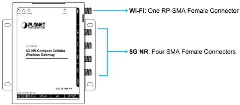
2.2.2 5G NR and Wi-Fi Antenna Installation
Fasten the 5G NR antenna extensions to the 5G NR connectors and the wireless antenna to the wireless connector.
2.2.3 Wiring the Power Inputs
The 6-contact terminal block connector on the bottom panel of Cellular Gateway is used for DC power inputs. Please follow the steps below to insert the power wire.

When performing any of the procedures like inserting the wires or tightening the wire-clamp screws, make sure the power is unplugged to prevent from getting an electric shock.
- Insert positive and negative DC power wires into contacts VCC and GND.
- Tighten the screws for preventing the wires from loosening.


2.2.4 Grounding the Device
User MUST complete grounding wired with the device; otherwise, a sudden lightning could cause fatal damage to the device. EMD (Lightning) DAMAGE IS NOT COVERED UNDER WARRANTY.
Chapter 3. Preparation
Before getting into the device's web UI, user has to check the network setting and configure PC's IP address.
3.1 Requirements
User is able to confirm the following items before configuration:
- Please confirm the network is working properly; it is strongly suggested to test your network connection by connecting your computer directly to ISP.
- Suggested operating systems: Windows 7 / 8 / 10./11
- Recommended web browsers: Microsoft Edge / Chrome. / Firefox
3.2 Setting TCP/IP on your PC
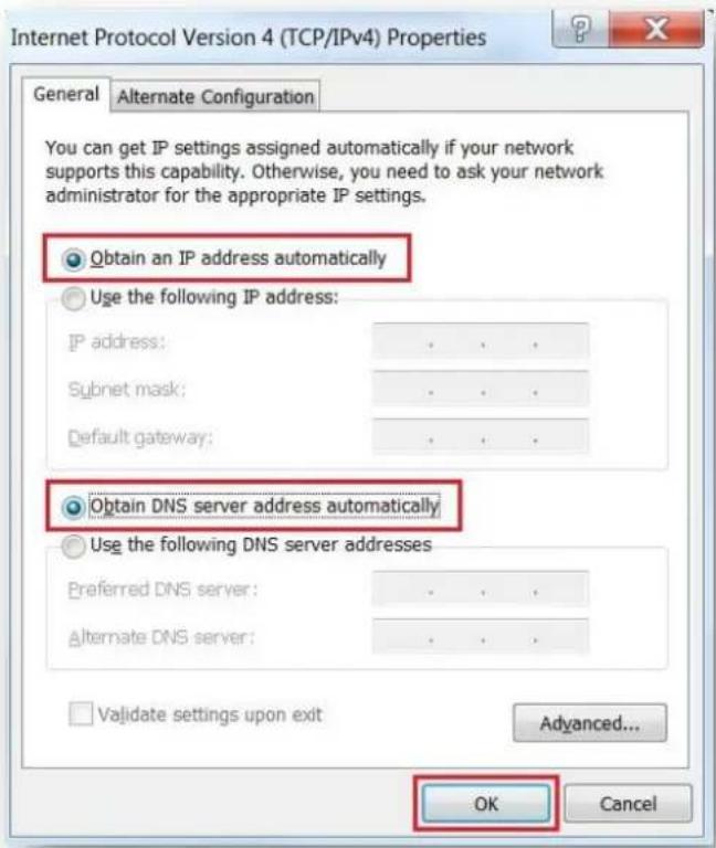
The default IP address of the cellular gateway is 192.168.1.1, and the DHCP Server is on. Please set the IP address of the connected PC as DHCP client, and the PC will get IP address automatically from the VPN cellular gateway
Please refer to the following to set the IP address of the connected PC.
Windows 7/8
If you are using Windows 7/8, please refer to the following:
- Click on the network icon from the right side of the taskbar and then click on "Open Network and Sharing Center".

- Click "Change adapter settings".

- Right-click on the Local Area Connection and select Properties.

- Select Internet Protocol Version 4 (TCP/IPv4) and click Properties or directly double-click on Internet Protocol Version 4 (TCP/IPv4).

- Select "Use the following IP address" and "Obtain DNS server address automatically", and then click the "OK" button.

Windows 10
If you are using Windows 10, please refer to the following:
- In the search box on the taskbar, type "View network connections", and then select View network connections at the top of the list.

- Right-click on the Local Area Connection and select Properties.

- Select Internet Protocol Version 4 (TCP/IPv4) and click Properties or directly double-click on Internet Protocol Version 4 (TCP/IPv4).

- Select "Use the following IP address" and "Obtain DNS server address automatically", and then click the "OK" button.
3.3 Planet Smart Discovery Utility
For easily listing the cellular gateway in your Ethernet environment, the search tool -- Planet Smart Discovery Utility -- is an ideal solution.
The following installation instructions are to guide you to running the Planet Smart Discovery Utility.
- Download the Planet Smart Discovery Utility in administrator PC.
- Run this utility as the following screen appears.

Figure 3-1-6: Planet Smart Discovery Utility Screen

If there are two LAN cards or above in the same administrator PC, choose a different LAN card by using the "Select Adapter" tool.
- Press the "Refresh" button for the currently connected devices in the discovery list as the screen shows below:

Figure 3-1-7: Planet Smart Discovery Utility Screen
- This utility shows all necessary information from the devices, such as MAC address, device name, firmware version, and device IP subnet address. It can also assign new password, IP subnet address and description to the devices.
- After setup is completed, press the "Update Device", "Update Multi" or "Update All" button to take effect. The functions of the 3 buttons above are shown below:
■ Update Device: use current setting on one single device.
■ Update Multi: use current setting on choose multi-devices.
■ Update All: use current setting on whole devices in the list.
The same functions mentioned above also can be found in "Option" tools bar.
- To click the "Control Packet Force Broadcast" function, it allows you to assign a new setting value to the device under a different IP subnet address.
- Press the "Connect to Device" button and the Web login screen appears.
Press the "Exit" button to shut down the Planet Smart Discovery Utility.
Chapter 4. Web-based Management
This chapter provides setup details of the device's Web-based Interface.
4.1 Introduction
The device can be configured with your Web browser. Before configuring, please make sure your PC is under the same IP segment with the device.
4.2 Logging in to the Cellular Gateway
Refer to the steps below to configure the cellular gateway:
Step 1. Connect the IT administrator's PC and cellular gateway LAN port to the same hub / switch, and then launch a browser to link the management interface address which is set to https://192.168.1.1 by default.

The DHCP server of the cellular gateway is enabled. Therefore, the LAN PC will get IP from the VPN cellular gateway. If user needs to set IP address of LAN PC manually, please set the IP address within the range between 192.168.1.2 and 192.168.1.254 inclusively, and assigned the subnet mask of 255.255.255.0.

The following steps are based on the firmware version before September of 2024.
Step 2. The browser prompts you for the login credentials.
Default IP address: 192.168.1.1
Default user name: admin
Default Password: admin
Default SSID (2.4G): PLANET_2.4G
Default SSID (5G): PLANET_5G
If you log in to the Web page for the first time, you can see the page shown below, prompting the user whether to modify the default username and password of the 5G industrial cellular gateway. If you need to enter the user-defined username and password, click the "Change Password" button to apply.
Your Router is currently not protected and uses an unsafe default username and password combination, please change it using the following dialog!
Router Password
Router Username
Router Password
Re-enter to confirm
admin
●●●●●
•••••
Figure 4-2-1: Account Setting Screen

The following steps are based on the firmware version of September of 2024 or after.
When the following dialog box appears, please enter the default user name and password. Refer to Figure 4-2-2 to determine your initial login password.
Default IP Address: 192.168.1.1
Default Username: admin
Default Password: cg + the last 6 characters of the MAC ID in lowercase
Default SSID (2.4G): PLANET_2.4G
Default SSID (5G): PLANET_5G
Find the MAC ID on your device label. The default password is "cg" followed by the last six lowercase characters of the MAC ID.
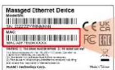
MAC ID: A8F7E0XXXXXX
Default Password: cgxxxxxx
("x" means the last 6 digits of the MAC address.
All characters should be in lowercase.)
Figure 4-2-2: MAC ID Label

Administrators are strongly suggested to change the default admin and password to ensure system security.
4.3 Main Web Page
After a successful login, the main web page appears. The web main page displays the menu and the system information.
Menu

Figure 4-3-1: Main Web Page
4.4 Setup
The Setup screen is the first screen you will see when accessing the cellular gateway. Most users will be able to configure the cellular gateway and get it working properly using only the settings on this screen. Some Internet Service Providers (ISPs) will require that you enter specific information, such as User Name, Password, IP Address, Default Gateway Address, or DNS IP Address. This information can be obtained from your ISP, if required.
4.4.1 Basic Setup
This page is used to configure the parameters for Internet network which connects to the WAN port of the cellular gateway. Here you may select the access method by clicking the item value of WAN access type.
4.4.1.1 WAN Setup
■ Disable
Forbid the setting of WAN port connection type
Main WAN Connection Type
Connection Type
Disabled

■ Static IP
Select Static IP Address if all the Internet port's IP information is provided to you by your ISP. You will need to enter the IP Address, Subnet Mask, Gateway and DNS Server provided to you by your ISP. Each IP address entered in the fields must be in the appropriate IP form, which are four octets separated by a dot (x.x.x.x). The cellular gateway will not accept the IP address if it is not in this format.
Main WAN Connection Type
Connection Type
WAN IP Address
Subnet Mask
Gateway
Static DNS 1
Static DNS 2
Static DNS 3

| Object | Description |
| WAN IP Address | Enter the IP address assigned by your ISP. |
| Subnet Mask | Enter the Subnet mask assigned by your ISP. |
| Gateway | Enter the Gateway assigned by your ISP. |
| Static DNS 1/2/3 | The DNS server information will be supplied by your ISP. |
■ Automatic Configuration – DHCP
Select DHCP Client to obtain IP Address information automatically from your ISP.
Main WAN Connection Type
Connection Type
Automatic Configuration - DHCP
DHCP-4G
Main WAN Connection Type
Connection Type
User Name
Password
APN
Fixed WAN IP
Allow these authentication
Connection type
PIN







The IP address of the WAN port is obtained in DHCP-4G/5G mode. The Auto connection type is a default, and at the same time, the NSA and SA are offered. This option is best set to separate SA or separate NSA according to the actual network environment.
■ PPPoE
Main WAN Connection Type
Connection Type
User Name
Password


| Object | Description |
| User Name | Login users' ISP (Internet Service Provider) |
| Password | Login users' ISP |
■ 3G Link 1/3G Link 2
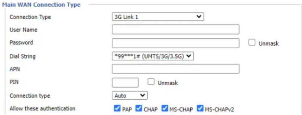
| Object | Description |
| Username | Login users' ISP (Internet Service Provider) |
| Password | Login users' ISP |
| Dial String | Dial number of users' ISP |
| APN | Access point name of users' ISP |
| PIN | PIN code of users' SIM card |
■ dhcp-bkup4G
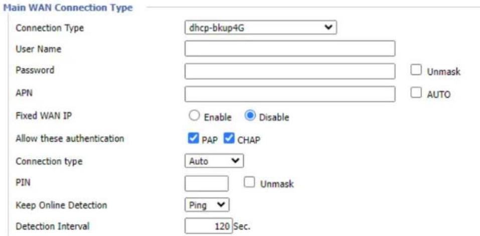
Primary Detection Server IP
Backup Detection Server IP
Enable Dial Failure to Restart
Fixed WAN Netmask Address
STP
Bridge Mode
Band


Enable

Disable

Enable

Disable

Enable

Disable

Enable

Disable

(Default: 10 minutes)
■ Keep Online Detection
This function is used to detect whether the Internet connection is active. If users set it and when the Cellular gateway detect the connection is inactive, it will redial to users' ISP immediately to make the connection active. If the network is busy or the user is in private network, we recommend that Cellular gateway mode will be better.
Keep Online Detection
Detection Interval
Primary Detection Server IP
Backup Detection Server IP
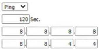
| Object | Description |
| None | Do not set this function |
| Ping | Send ping packet to detect the connection when choosing this method. Users should also configure "Detection Interval", "Primary Detection Server IP" and "Backup Detection Server IP" items. |
| Route | Detect connection with route method when choosing this method.Users should also configure "Detection Interval", "Primary Detection Server IP" and "Backup Detection Server IP" items. |
| PPP | Detect connection with PPP method when choosing this method.Users should also configure "Detection Interval" item. |
| Detection Interval | Time interval between two detections; unit is second. |
| Primary DetectionServer IP | The server is used to respond the cellular gateway detected packet.This item is only valid for the "Ping" and "Route" method. |
| Backup DetectionServer IP | The server is used to respond the cellular gateway detected packet.This item is valid for the "Ping" and "Route" method. |
Note: When users choose the "Route" or "Ping" method, it's quite important to make sure that the "Primary Detection Server IP" and "Backup Detection Server IP" are usable and stable, because they have to respond the detected packet frequently.
STP
STP (Spanning Tree Protocol) can be applied to loop network. By employing specific algorithms, the system achieves path redundancy and transforms a loop network into a tree-based network without introducing loops. This prevents message hyperplasia and infinite circulation within the network loop.
STP

Enable

Disable
■ Optional Configuration
Optional Settings
Router Name
PLANET Cellular Wireless G
Host Name

Domain Name

MTU


Force Net Card Mode
| Object | Description |
| Router Name | Set the cellular gateway name |
| Host Name | Provided by ISP |
| Domain Name | Provided by ISP |
| MTU | Auto (1500) and manual (1200-1492 in PPPOE/PPTP/L2TP mode, 576-16320 in other modes) |
| Force Net Card Mode | Force to set the speed of WAN port |
4.4.1.2 Network Setup
Router IP
Router IP
| Local IP Address | 192 | 168 | 1 | 1 |
| Subnet Mask | 255 | 255 | 255 | 0 |
| Object | Description |
| Local IP Address | IP address of the cellular gateway |
| Subnet Mask | The subnet mask of the cellular gateway |
■ Multiple LAN IP
The cellular gateway offers several LAN IP addresses for web access.
Multiple LAN IP
| Choose | NUM | IP ADDR | NETMASK |
| 1 | 192.168.3.4 | 255.255.255.0 | |
| 2 | 192.168.3.100 | 255.255.255.0 | |
| Delete | Add | 0. 0. 0. 0 | 0. 0. 0. 0 |
■ Network Address Server Settings (DHCP)
These configurations pertain to the setup of the Dynamic Host Configuration Protocol (DHCP) server within the cellular gateway functionality. The cellular gateway can serve as a network DHCP server. DHCP server automatically assigns an IP address to each computer in the network. If they choose to enable the DHCP server option of the of cellular gateway, users can set all the computers on the LAN to automatically obtain an IP address and DNS, and make sure no other DHCP server is in the network.
Network Address Server Settings (DHCP)
| DHCP Type | DHCP Server | |
| DHCP Server | Enable | Disable |
| Start IP Address | 192.168.1 | 100 |
| Maximum DHCP Users | 100 | |
| Client Lease Time | 1440 minutes | |
| Static DNS 1 | 0 | 0 |
| Static DNS 2 | 0 | 0 |
| Static DNS 3 | 0 | 0 |
| WINS | 0 | 0 |
| Use DNSMasq for DHCP | ||
| Use DNSMasq for DNS | ||
| DHCP-Authoritative | ||
| Object | Description |
| DHCP Server | Keep the default “Enabled” for the DHCP server option of the cellular gateway to be operational. If users have already had a DHCP server on their network or users do not want a DHCP server, select Disable |
| Start IP Address | Enter a numerical value for the DHCP server to start with when issuing IP addresses. Do not start with 192.168.1.1 (the cellular gateway has its own IP address). |
| Maximum DHCP Users | Enter the maximum number of PCs that users want the DHCP server to assign IP addresses to. The absolute maximum is 253 if 192.168.1.2 is users' starting IP address. |
| Client Lease Time | The Client Lease Time is the amount of time a network user will be allowed to connect to the cellular gateway with their current dynamic IP address. Enter the amount of time, in minutes, that the user will be "leased", using this dynamic IP address. |
| Static DNS (1-3) | The Domain Name System (DNS) is how the Internet translates domain or website names into Internet addresses or URLs. Users' ISP will provide them with at least one DNS Server IP address. If users wish to utilize another, enter that IP address in one of these fields. Users can enter up to three DNS Server IP addresses here. The cellular gateway will utilize them for quicker access to functioning DNS servers. |
| WINS | The Windows Internet Naming Service (WINS) manages each PC's interaction with the Internet. If users use a WINS server, enter thatserver's IP address here. Otherwise, leave it blank. |
| DNSMasq | Users' domain name in the field of local search increases the expansion of the host option to adopt DNSMasq that can assign IP addresses and DNS for the subnet. If DNSMasq is selected, DHCPD service is used for the subnet IP address and DNS. |
DHCP Forwarder
Network Address Server Settings (DHCP)
DHCP Type
DHCP Server
DHCP Forwarder ▼

■ Time Settings
Select time zone of your location. To use local time, leave the checkmark in the box next to Use local time. And to adjust time by the system and refresh to get the time of the web, user can set to modify the time of the system. The time settings can be manually adjusted if the system fails to connect to the NTP server, enabling users to make necessary time adjustments
Time Settings
NTP Client
Time Zone
Summer Time (DST)
Server IP/Name

Enable

Disable
UTC-12:00
none

Adjust Time
Auto


| Object | Description |
| NTP Client | Get the system time from NTP server |
| Time Zone | Time zone options |
| Summer Time (DST) | Set it (depending on users' location) |
| Server IP/Name | IP address of NTP server, up to 32 characters. If blank, the system will find a server by default |
4.4.2 DDNS
If user's network has a permanently assigned IP address, users can register a domain name and have that name linked with their IP address by public Domain Name Servers (DNS). However, if their Internet account uses a dynamically assigned IP address, users will not know in advance what their IP address will be, and the address can change frequently. In this case, users can use a commercial dynamic DNS service, which allows them to register their domain to their IP address and will forward traffic directed at their domain to their frequently-changing IP address.



| Object | Description |
| DDNS Service | Cellular gateway currently supports PLANET DDNS, PLANET easyDDNS, DynDNS, NO-IP, easyDNS, TZO, DynSIP and Custom based on the user. |
| Username | Users register in DDNS server, up to 64 characters for password |
| Host Name | Users register in DDNS server, not limited to input characters for now |
| Type | depending on the server |
| Wildcard | Supports wildcard or not, the default is OFF. ON means*.host.3322.org is equal to host.3322.org |
| Don’t Use External IP Check | Enable or disable the function of 'do not use external IP check'. |
| Force Update Interval | The unit is a day; attempt to trigger the dynamic DNS update to the server at specified intervals. |
| DDNS Status | DDNS Status shows connection log information |
4.4.3 MAC Address Clone
Some ISPs need the users to register their MAC address. The users can clone the cellular gateway MAC address to their MAC address registered in ISP if they do not want to re-register their MAC address

| Object | Description |
| Clone MAC address | Can clone three parts: Clone LAN MAC, Clone WAN MAC,and Clone Wireless MAC. |
Note: The MAC address comprises 48 characters and cannot be assigned as a multicast address; the first byte must be an even value. The MAC address for the network bridge, br0, is determined by the smaller value between the wireless MAC address and the LAN port MAC address.
4.4.4 Advanced Routing
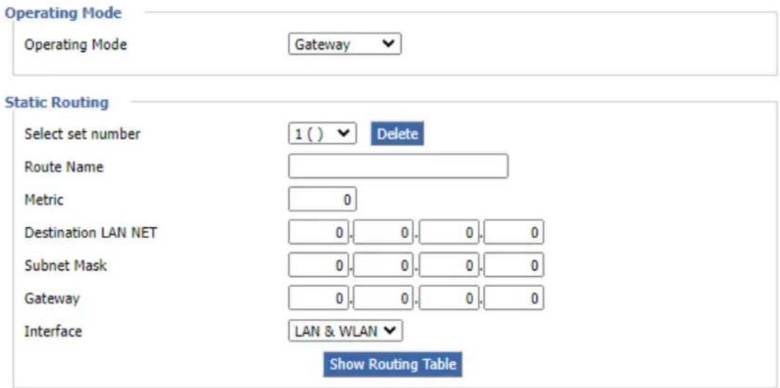
On the Routing screen, you can set the routing mode and settings of the cellular gateway. Gateway mode is recommended for most users.
| Object | Description |
| Operating Mode | If the cellular gateway is hosting your Internet connection, select Gateway mode. If another router exists on your network, select Router mode. |
| Dynamic Routing | Dynamic Routing enables the cellular gateway to automatically adjust to physical changes in the network's layout and exchange routing tables with other routers. The cellular gateway determines the network packets' route based on the fewest number of hops between the source and destination. |
| Subnet Mask | The Subnet Mask determines which portion of an IP address is the network portion, and which portion is the host portion |
| Gateway | IP address of the gateway device that allows for contact between the cellular gateway and the network or host. |
| Interface | Indicate users whether the Destination IP Address is on the LAN and WLAN (internal wired and wireless networks), the WAN (Internet), or Loopback (a dummy network in which one PC acts like a network, necessary for certain software programs) |
Click "Show Routing Table" for the Routing Table Entry List.
Routing Table Entry List
| Destination LAN NET | Subnet Mask | Gateway | Interface |
| 192.168.1.0 | 255.255.255.0 | 0.0.0.0 | LAN & WLAN |
| 192.168.3.0 | 255.255.255.0 | 0.0.0.0 | LAN & WLAN |
| 192.168.3.0 | 255.255.255.0 | 0.0.0.0 | WAN |
Refresh
dose
4.4.5 VLANs
VLANs function is to divide different VLAN ports by users' will. The system accommodates 14 VLAN ports, ranging from VLAN1 to VLAN14. Users can only allocate two ports independently, as the LAN port and WAN port cannot be separated into individual VLAN ports simultaneously.
VLAN

4.4.6 Networking
4.4.6.1 Bridging

| Object | Description |
| Bridging: Create Bridge | Creates a new empty network bridge for later use. STP means Spanning Tree Protocol and with PRIO users can set the bridge priority order. The lowest number has the highest priority. |
| Bridging: Assign to Bridge | Allows users to assign any valid interface to a network bridge.Consider setting the Wireless Interface options to Bridged if they want to assign any Wireless Interface here. Any system specific bridge setting can be overridden here in this field. |
| Current Bridging Table | Shows current bridging table |
Create steps as shown below:
Click 'Add' to create a new bridge for the configuration shown below:

Create bridge option: the first br0 means bridge name. Select on/off spanning tree protocol. Prio means priority level of STP; the smaller the number, the higher the level. MTU means maximum transfer unit whose default is 1500. Delete if it is not needed. And then click 'Save' or 'Add' for bridge properties as shown below:
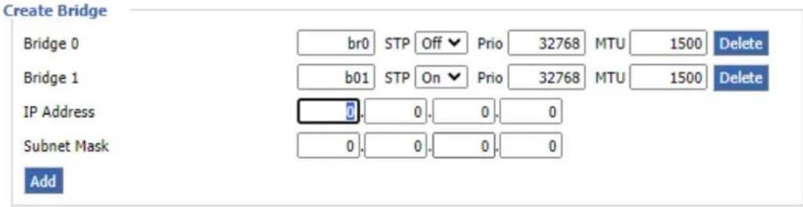
Enter a relevant bridge IP address and subnet mask. Click 'Add' to create a bridge.
Note: Only creating a bridge can be applied.

Assign to Bridge option: To assign a different port to create a bridge. For example, assigned port (wireless port) is ra0 in br1 bridge as shown below:
Prio means priority level: It will work if multiple ports are within the same bridge. The smaller the number is, the higher the level will be. Click 'Add' to take it effect.
Note: The interface corresponding to WAN ports should not be bound. This bridge function is primarily designed for LAN ports and should not be bound to WAN ports. In the event of a successful binding, the bridge binding list in the current bridging table appears as follows:

To enable the br1 bridge to have the same functionality as a DHCP-assigned address, users need to configure multiple DHCP functions. Refer to the documentation on multi-channel DHCPD for more information.
4.4.6.2 Port Setup
Set the port property; the default is not set
Port Setup
| Network Configuration eth1 | ○ Unbridged | ● Default |
| Network Configuration vlan1 | ○ Unbridged | ● Default |
| Network Configuration vlan3 | ○ Unbridged | ● Default |
| Network Configuration vlan2 | ○ Unbridged | ● Default |
| Network Configuration br1 | ○ Unbridged | ● Default |
| Network Configuration br0 | ○ Unbridged | ● Default |
Choose "unbridged" to set the port's own properties.
| Network Configuration eth1 | ● Unbridged ○ Default |
| MTU | 1500 |
| Multicast forwarding | ○ Enable ● Disable |
| Masquerade / NAT | ● Enable ○ Disable |
| IP Address | 0. 0. 0. 0 |
| Subnet Mask | 0. 0. 0. 0 |
| Object | Description |
| MTU | Maximum transfer unit |
| Multicast Forwarding | Enable or disable multicast forwarding |
| Masquerade/NAT | Enable or disable Masquerade/NAT |
| IP Address | Set IP address, making sure not to conflict with other ports or bridges |
| Subnet Mask | Set the port's subnet mask |
4.4.6.3 DHCPD

Multiple DHCPD: Using "multiple DHCP service"
Click on 'Add' in the multiple DHCP server settings to access the relevant configuration options. The first field is for specifying the port or bridge name (excluding eth0). The second field determines whether DHCP is enabled for this entry. 'Start' denotes the starting address, 'Max' indicates the maximum number of assigned DHCP clients, and 'Lease time' represents the client lease time in seconds. After configuring, click 'Save' or 'Apply' to implement the changes.
Note: Configuration for the next entry can only be done one at a time. After configuring, click 'Save' to proceed to the next configuration; simultaneous configuration of multiple DHCP entries is not supported.
4.5 Wireless
4.5.1 Basic Setting
Wireless Physical Interface w10 [2.4 GHz]
Wireless Network
![Planet ICG-2210W-NR - Wireless Physical Interface w10 [2.4 GHz] - 1](/content/2026/05/900931/images/08e32a3be058980809ba30902e5ef7d1841ec1dcd8fca892151ca0f68ff17f5d.jpg)
Enable
![Planet ICG-2210W-NR - Wireless Physical Interface w10 [2.4 GHz] - 2](/content/2026/05/900931/images/298e564dba9007d773b0fa20f5726f7ac4b00b33c21a34415cf5d4ca90e84664.jpg)
Disable
Physical Interface ath0 - SSID [PLANET_ICG-2210W-NR_2.4G] HWAddr [A8:F7:E0:39:6B:A1]
Wireless Mode
![Planet ICG-2210W-NR - Physical Interface ath0 - SSID [PLANET_ICG-2210W-NR_2.4G] HWAddr [A8:F7:E0:39:6B:A1] - 1](/content/2026/05/900931/images/16ac32348b6f0858b71effb5a7e81134cc253776367b8309e1e78187105ea3ec.jpg)
![Planet ICG-2210W-NR - Physical Interface ath0 - SSID [PLANET_ICG-2210W-NR_2.4G] HWAddr [A8:F7:E0:39:6B:A1] - 2](/content/2026/05/900931/images/cd18fc1521275b8f8f1c7ad23c5c119444dbb67c1d788c47c390f6159e03804f.jpg)
Wireless Network Mode
![Planet ICG-2210W-NR - Physical Interface ath0 - SSID [PLANET_ICG-2210W-NR_2.4G] HWAddr [A8:F7:E0:39:6B:A1] - 3](/content/2026/05/900931/images/493a1000d11b30d232d14fd01064ba14683c3600ea9f9866d355a6f3f27deefc.jpg)
![Planet ICG-2210W-NR - Physical Interface ath0 - SSID [PLANET_ICG-2210W-NR_2.4G] HWAddr [A8:F7:E0:39:6B:A1] - 4](/content/2026/05/900931/images/28cf1947584f1d1f9dc72e5f10f4d677e60d6c20563bad63240a3d8c6ab492ca.jpg)
Wireless Network Name (SSID)
![Planet ICG-2210W-NR - Physical Interface ath0 - SSID [PLANET_ICG-2210W-NR_2.4G] HWAddr [A8:F7:E0:39:6B:A1] - 5](/content/2026/05/900931/images/b0c4095f38e2f466772cab7150db7c5086fef0fa01841dcb97792be0ae26ffb4.jpg)
Wireless Channel
![Planet ICG-2210W-NR - Physical Interface ath0 - SSID [PLANET_ICG-2210W-NR_2.4G] HWAddr [A8:F7:E0:39:6B:A1] - 6](/content/2026/05/900931/images/c06d0a7456a3a6f885824cd4e251c23bb7cf380c47e9f9675a0542cbda412f9b.jpg)
![Planet ICG-2210W-NR - Physical Interface ath0 - SSID [PLANET_ICG-2210W-NR_2.4G] HWAddr [A8:F7:E0:39:6B:A1] - 7](/content/2026/05/900931/images/c0a0b476773ca0049ea5b42047e2746b7f93a2c478b4eaae161abf9939c6c1df.jpg)
Channel Width
![Planet ICG-2210W-NR - Physical Interface ath0 - SSID [PLANET_ICG-2210W-NR_2.4G] HWAddr [A8:F7:E0:39:6B:A1] - 8](/content/2026/05/900931/images/f102fb24e1fd092c6e70ab95a6118006a389f375465d098dcbae270e4b19f70e.jpg)
![Planet ICG-2210W-NR - Physical Interface ath0 - SSID [PLANET_ICG-2210W-NR_2.4G] HWAddr [A8:F7:E0:39:6B:A1] - 9](/content/2026/05/900931/images/e14c648b0adf8f20b4a9f942dbfb9665e29c7737b112e88ee4ecc0ae386edbe3.jpg)
Extension Channel
![Planet ICG-2210W-NR - Physical Interface ath0 - SSID [PLANET_ICG-2210W-NR_2.4G] HWAddr [A8:F7:E0:39:6B:A1] - 10](/content/2026/05/900931/images/3b7f39baddb569c48c27c80d38028dbdd2bf9cde3544cdd97d014d12f5b5abea.jpg)
![Planet ICG-2210W-NR - Physical Interface ath0 - SSID [PLANET_ICG-2210W-NR_2.4G] HWAddr [A8:F7:E0:39:6B:A1] - 11](/content/2026/05/900931/images/15c58910bc229da2858d9c815156c7efd914d723091413b6fb4bdd2c8c35220d.jpg)
Wireless SSID Broadcast
![Planet ICG-2210W-NR - Physical Interface ath0 - SSID [PLANET_ICG-2210W-NR_2.4G] HWAddr [A8:F7:E0:39:6B:A1] - 12](/content/2026/05/900931/images/aa1ba65a5030337a99eb62d4532056ebf08bc63d08efa2992a2bb06f9b942970.jpg)
Enable
![Planet ICG-2210W-NR - Physical Interface ath0 - SSID [PLANET_ICG-2210W-NR_2.4G] HWAddr [A8:F7:E0:39:6B:A1] - 13](/content/2026/05/900931/images/19b9697808cf71d39bc75cf45524b13db31b623b130de30e3b274cf59a65b607.jpg)
Disable
Virtual Interfaces
Add
Wireless Physical Interface w10_5G [5 GHz]
Wireless Network
![Planet ICG-2210W-NR - Wireless Physical Interface w10_5G [5 GHz] - 1](/content/2026/05/900931/images/2a60830bf4066c1a794d819689c5dfbe8cd24a390ddf86f5e7da5538ac5beaf7.jpg)
Enable
![Planet ICG-2210W-NR - Wireless Physical Interface w10_5G [5 GHz] - 2](/content/2026/05/900931/images/0f107b5882e6af02a674d563477aac243ce01303f0fa92b1d1cca0c5d7580fd0.jpg)
Disable
Physical Interface ath1 - SSID [PLANET_ICG-2210W-NR_5G] HWAddr [A8:F7:E0:39:6B:A2]
Wireless Mode
![Planet ICG-2210W-NR - Physical Interface ath1 - SSID [PLANET_ICG-2210W-NR_5G] HWAddr [A8:F7:E0:39:6B:A2] - 1](/content/2026/05/900931/images/bdb4f544da160c25e809f83c5417fb0c08380ee8ac17bb9a6a0d91cc208342ca.jpg)
![Planet ICG-2210W-NR - Physical Interface ath1 - SSID [PLANET_ICG-2210W-NR_5G] HWAddr [A8:F7:E0:39:6B:A2] - 2](/content/2026/05/900931/images/b80758e46929271852d2d7b75211a253e220cc86237a9547fd25eab2d7a3be3e.jpg)
Wireless Network Mode
![Planet ICG-2210W-NR - Physical Interface ath1 - SSID [PLANET_ICG-2210W-NR_5G] HWAddr [A8:F7:E0:39:6B:A2] - 3](/content/2026/05/900931/images/10e32942033d53692dfef71b925726d4ad6b576ff42e4fa42bcdaee7ae98a049.jpg)
![Planet ICG-2210W-NR - Physical Interface ath1 - SSID [PLANET_ICG-2210W-NR_5G] HWAddr [A8:F7:E0:39:6B:A2] - 4](/content/2026/05/900931/images/6713048f796f87538b797bca615be3c8bc7eba55bc23356aba723da5b431c8ca.jpg)
Wireless Network Name (SSID)
![Planet ICG-2210W-NR - Physical Interface ath1 - SSID [PLANET_ICG-2210W-NR_5G] HWAddr [A8:F7:E0:39:6B:A2] - 5](/content/2026/05/900931/images/faf9b8379e71d12b6976eb856a3e9c0553414fc709de65a18f8f2678946918a7.jpg)
Wireless Channel
![Planet ICG-2210W-NR - Physical Interface ath1 - SSID [PLANET_ICG-2210W-NR_5G] HWAddr [A8:F7:E0:39:6B:A2] - 6](/content/2026/05/900931/images/56583b03278d32715cf5e179654c12ce98ce1bcc31eb2034e21ce754e292697e.jpg)
Channel Width
![Planet ICG-2210W-NR - Physical Interface ath1 - SSID [PLANET_ICG-2210W-NR_5G] HWAddr [A8:F7:E0:39:6B:A2] - 7](/content/2026/05/900931/images/4e0958ce5936b35f5c0e01b8eacd339bad3fc204cd8e11a90467dd643716610b.jpg)
![Planet ICG-2210W-NR - Physical Interface ath1 - SSID [PLANET_ICG-2210W-NR_5G] HWAddr [A8:F7:E0:39:6B:A2] - 8](/content/2026/05/900931/images/3019e7325c479cfd828281d3f52c8ed95786b988353ae9a81cc3f62d7e8a6e5a.jpg)
Wireless SSID Broadcast
![Planet ICG-2210W-NR - Physical Interface ath1 - SSID [PLANET_ICG-2210W-NR_5G] HWAddr [A8:F7:E0:39:6B:A2] - 9](/content/2026/05/900931/images/6abb297ef640b8a6e1010d3c09ef6bfdc40a75f379477093fa2cb9ad7064e678.jpg)
Enable
![Planet ICG-2210W-NR - Physical Interface ath1 - SSID [PLANET_ICG-2210W-NR_5G] HWAddr [A8:F7:E0:39:6B:A2] - 10](/content/2026/05/900931/images/59056045fd4ecaa0868321ddee957137c7c83b60317c008af26ca1662310ce1d.jpg)
Disable
Virtual Interfaces
Add
| Object | Description |
| Wireless Network | Allows user to enable or disable Wi-Fi radio |
| Wireless Mode | Supports AP, Client, and Repeater modes. |
| Wireless Network Mode | 2.4 GHzMixed: Supports 802.11b, 802.11g and 802.11n wireless devices.BG-Mixed: Supports 802.11b and 802.11g wireless devices.B-only: Only supports the 802.11b standard wireless device.G-only: Only supports the 802.11g standard wireless device.NG-Mixed: Supports 802.11g and 802.11n wireless devices.N-only: Only supports the 802.11g standard wireless devices.5 GHzna: Supports 802.11a and 802.11n wireless devices.ac: Support 802.11ac wireless devices. |
| Wireless Network Name (SSID) | It is the wireless network name.The default 2.4GHz SSID is “PLANET_2.4G”The default 5GHz SSID is “PLANET_5G” |
| Wireless Channel | It shows the channel of the CPE. |
| Channel Width | Select the operating channel width.2.4GHz: “20MHz”, “40MHz” or “Auto”5GHz: “20MHz”, “40MHz”, “80MHz” or “Auto” |
| Extension Channel | Channel for 40MHz (2.4GHz); you can choose upper or lower. |
| Wireless SSID Broadcast | Allows user to enable or disable SSID broadcasting |
Virtual Interfaces
Virtual Interfaces ath01 SSID [PLANET_2.4G_1]
Wireless Network Name (SSID)
Wireless SSID Broadcast
AP Isolation
PLANET_2.4G_1

Enable

Disable

Enable

Disable
Add
Remove
Virtual Interfaces
Virtual Interfaces ath11 SSID [PLANET_5G_1]
Wireless Network Name (SSID)
Wireless SSID Broadcast
AP Isolation
PLANET_5G_1

Enable

Disable

Enable

Disable
Add
Remove
Virtual Interfaces : Click Add to add a virtual interface. Click on Remove to remove the virtual interface.
| Object | Description |
| Wireless Network Name (SSID) | It is the wireless network name.The default 2.4GHz SSID is “PLANET_2.4G_1”The default 5GHz SSID is “PLANET_5G_1” |
| Wireless SSID Broadcast | Allows user to enable or disable SSID broadcasting |
| AP Isolation | This setting isolates wireless clients, so access to and from other wireless clients are stopped. |
Note: Save your changes after changing the "Wireless Mode". Click on the "Wireless Network Mode," "Wireless Width," and "Broadband" options to proceed to configure the additional settings.
4.5.2 Wireless Security
Wireless security options are used to configure the security of your wireless network. It has a total of seven wireless security modes. Disabled by default, it is not a safe mode. For a safe mode, click
Apply to take effect immediately.
Wireless Security w10
Physical Interface ath0 SSID [PLANET_ICG-2210W-NR_2.4G] HWAddr [A8:F7:E0:39:6B:A1]
Security Mode
Disabled
Wireless Security w10_5G
Physical Interface ath1 SSID [PLANET_ICG-2210W-NR_5G] HWAddr [A8:F7:E0:39:6B:A2]
Security Mode
Disabled
Security mode supports WEP, WPA Personal, WPA Enterprise, WPA2 Personal, WPA2 Enterprise, WPA2 Personal Mixed and WPA2 Enterprise Mixed.

■ WEP
| Object | Description |
| Authentication Type | Open or shared key |
| Default Transmit Key | Select Key 1 |
| Encryption | There are two levels of WEP encryption, 64-bit (40-bit) and 128-bit. To utilize WEP, select the desired encryption bit, and enter a passphrase or up to four WEP keys in the hexadecimal format. If you are using 64-bit (40-bit), then each key must consist of exactly 10 hexadecimalcharacters or 5 ASCII characters. For 128-bit, each key must consist of exactly 26 hexadecimal characters. Valid hexadecimal characters are "0"-"9" and "A"-"F". |
| ASCII and HEX | For ASCII, the keys are either 5-bit ASCII characters or 13-bit ASCII characters.For HEX, the keys consist of either 10-bit or 26-bit hex digits. |
| Passphrase | The letters and numbers are used to generate a key. |
| Key1 | Fill out or generate the passphrase. |
Note: WEP is a basic encryption algorithm that is less secure than WPA. Use of WEP is discouraged due to security weaknesses, and one of the WPA modes should be used whenever possible. Only use WEP if you have clients that can only support WEP (usually older, 802.11b-only clients).
■ WPA Personal/WPA2 Personal/WPA2 Person Mixed
Wireless Security w10
Physical Interface ath0 SSID [PLANET_ICG-2210W-NR_2.4G] HWAddr [A8:F7:E0:39:6B:A1]
Security Mode
WPA Algorithms
WPA Shared Key
Key Renewal Interval (in seconds)
WPA Personal
TKIP+AES
●●●●●●●
3600

□ Unmask
(Default: 3600, Range: 1 - 99999)
| Object | Description |
| WPA Algorithms | TKIP/AES/TKIP+AES, dynamic encryption keysTKIP+AES is self-applicable (TKIP or AES) |
| WPA Shared Key | Between 8 and 63 ASCII characters or hexadecimal digits. |
| Key Renewal Interval(In seconds ) | 1-99999 |
| ASCII and HEX | For ASCII, the keys are either 5-bit ASCII characters or 13-bit ASCII characters.For HEX, the keys consist of either 10-bit or 26-bit hex digits. |
| Passphrase | The letters and numbers are used to generate a key. |
| Key1 | Fill out or generate the passphrase. |
4.6 Services
DHCP Server
DHCP assigns IP addresses to users' local devices. While the main configuration is on the setup page users can program some nifty special functions here.
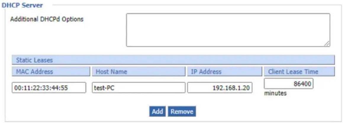
Static Leases: If users want to assign certain hosts a specific address, then they can define them here. This is also the way to add hosts with a fixed address to the local DNS service (DNSMasq) of the cellular gateway
| Object | Description |
| Additional DHCPd Options | Some extra options users can set by entering them |
| MAC Address | The MAC address of specific client to which you want to assign. |
| Host Name | The specific name of the client. |
| IP Address | The specific IP address to which you want to assign. |
| Client Lease Time | IP address release time. |
DNSMasq
DNSmasq is a local DNS server. It will resolve all host names known to the cellular gateway from DHCP (dynamic and static) as well as forwarding and caching DNS entries from remote DNS servers. Local DNS enables DHCP clients on the LAN to resolve static and dynamic DHCP host names. There are some extra options you can set by entering them in Additional DNS Options.
DNSMasq
DNSMasq
Local DNS
No DNS Rebind
Additional DNSMasq Options

Enable

Disable

Enable

Disable

Enable

Disable
| Object | Description |
| Local DNS | Enables DHCP clients on the LAN to resolve static and dynamic DHCP host names. |
| No DNS Rebind | When enabled, it can prevent an external attacker to access the internal Web interface of the cellular gateway. It is a security measure. |
| Additional DNSMasq Options | Some extra options users can set by entering them in Additional DNS Options. |
| IP Address | The specific IP address to which you want to assign.For example:Static Allocation: Dhcp-host=AB:CD:EF:11:22:33,192.168.0.10,myhost,myhost.domain,12hMax Lease Number: Dhcp-lease-max=2DHCP Server IP Range: Dhcp-range=192.168.0.110,192.168.0.111,12h |
SNMP
SNMP
SNMP
Location
Contact
Name
RO Community
RW Community

Enable

Disable
Default Location
Default Contact
ICG-2210W-NR
public
private
| Object | Description |
| Enable SNMP | Disable or enable the SNMP function.The default configuration is disabled. |
| Location | Allows entering characters for system location of the cellular gateway. |
| Contact | Allows entering characters for system contact of the cellular gateway. |
| Name | Allows entering characters for system name of the cellular gateway. |
| RO Community | Allows entering characters for SNMP Read Community of the cellular gateway |
| RW Community | Allows entering characters for SNMP Write Community of the cellular gateway |
Location: Equipment location
Contact: Contact this equipment management
Name: Device name
RO Community: SNMP RO community name; the default is public, only to read. RW Community:
SNMP RW community name; the default is private, Read-write permissions
- Secure Shell
Enabling SSHd allows users to access the Linux OS of their cellular gateway with an SSH client
Secure Shell
SSHd

Enable

Disable
SSH TCP Forwarding

Enable

Disable
Password Login

Enable

Disable
Port
22
(Default: 22)
Authorized Keys

| Object | Description |
| SSH TCP Forwarding | Enable or disable to support the TCP forwarding. |
| Password Login | Allows login with the cellular gateway password (username is admin) |
| Port | Port number for SSHd (default is 22) |
| Authorized Keys | Here users paste their public keys to enable key-based login (more secure than a simple password) |
System log
Enable Syslog to capture system messages. By default, they will be collected in the local file /var/log/messages. To send them to another system, enter the IP address of a remote syslog server.
System Log
| Syslogd | ● Enable ○ Disable |
| Syslog Out Mode | ○ Net ● Console ○ Web |
| Cache Log | ○ Enable ● Disable |
System Log
| Syslogd | Enable Disable |
| Syslog Out Mode | Net Console Web |
| Remote Server | |
| Cache Log | Enable Disable |
| Cache Log Interval(s) | 300 |
| Object | Description |
| Syslog Out Mode | Net: The log information output to a syslog serverConsole: The log information output to console port |
| Password Login | Allows login with the cellular gateway password (username is admin) |
| Remote Server | If net mode is chosen, users should input a syslog server's IP Address and run a syslog server program on it. |
Telnet
Enable a telnet server to connect to the cellular gateway with telnet. The username is admin and the password is the cellular gateway's password.
Telnet
| Telnet | ● Enable | ○ Disable |
Note: If users use the cellular gateway in an untrusted environment (for example as a public hotspot), it is strongly recommended to use SSHd and deactivate telnet.
■ WAN Traffic Counter
WAN Traffic Counter
ttraff Daemon

Enable

Disable
ttraff Daemon: Enable or disable WAN traffic counter function
4.7 VPN
4.7.1 PPTP
PPTP (Point-to-Point Tunneling Protocol) is a network protocol for secure communication over a public network. Commonly used in VPNs, it establishes a secure tunnel for transmitting data by encapsulating it within Internet Protocol (IP) packets. While widely supported, PPTP is considered less secure than more modern VPN protocols due to vulnerabilities.
■ PPTP Server
A VPN technology by Microsoft and remote access vendors -- It is implemented in Windows XP. Configuring this allows you to access your LAN at home remotely.

| Object | Description |
| Broadcast Support | Enable or disable broadcast support of PPTP server |
| Force MPPE Encryption | Enable of disable force MPPE encryption of PPTP data |
| DNS1/DNS2/WINS1/WINS2 | Set DNS1/DNS2/WINS1/WINS2 |
| Server IP | Input IP address of the cellular gateway as PPTP server, different from LAN address |
| Client IP(s) | A list or range of IP addresses for remotely connected machines.This range should not overlap with the DHCP range (For example, 192.168.0.2,192.168.0.3), a range (For example, 192.168.0.1-254 or 192.168.0-255.2) or some combination (For example, 192.168.0.2,192.168.0.5-8). |
| CHAP Secrets | A list of usernames and passwords for the VPN login; one user per line (For example, joe * joespassword *). For more details, look up the pppd main page. |
Note: Client IP must be different from IP assigned by cellular gateway DHCP. The format of CHAP Secrets is user * password *.
■ PPTP Client
A VPN Client that enables you to connect to VPN servers by Microsoft and remote access vendors. Configuring this allows the cellular gateway to VPN in a remote network.
PPTP Client
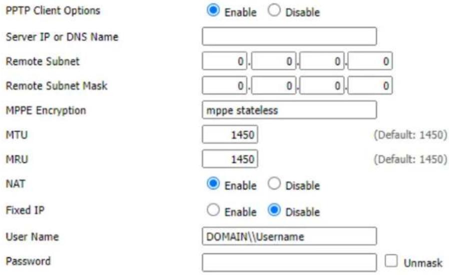
| Object | Description |
| Server IP or DNS Name | The IP address or DNS Name of the VPN server that you would like to connect to |
| Remote Subnet | Remote Subnet of the network you are connecting to |
| Remote Subnet Mask | Remote Subnet Mask of the network you are connecting to |
| MPPE Encryption | Enable or disable Microsoft Point-to-Point EncryptionThe type of security to use for the connection. If you are connecting to another cellular gateway you need (For example, mppe is required).But if you are connecting to a Windows VPN server you need (For example, mppe is required, no40,no56, stateless) or (For example, mppe is required, no40,no56, stateful) |
| MTU | Default Maximum Transmission Unit (Default: 1450) |
| MRU | Default Maximum Receiving Unit (Default: 1450) |
| NAT | Network Address Translation |
| Username | Enter the Username that you will use to connect to the VPN server. If you are connecting to another LINUX-based PPTP server you just need to enter the Username (like admin). But if you are connecting to a Windows VPN server you need to enter the servername and username (Like DOMAIN\UserName). |
| Password | Enter the password of the username |
4.7.2 L2TP
L2TP (Layer 2 Tunneling Protocol) is a network protocol that facilitates the creation of virtual private networks (VPNs). It operates at the data link layer and combines the strengths of PPTP and L2F. L2TP provides secure communication by creating tunnels for transmitting data over the Internet, often used in conjunction with IPsec for enhanced security.
L2TP Server
A VPN technology by Microsoft and remote access vendors -- It is implemented in Windows XP. Configuring this allows you to access your LAN at home remotely.

| Object | Description |
| Force MPPE Encryption | Enable or disable force MPPE encryption of L2TP data |
| Server IP | Input IP address of the cellular gateway as L2TP server, different from LAN address |
| Client IP(s) | A list or range of IP addresses for remotely connected machines.This range should not overlap with the DHCP range (For example, 192.168.0.2,192.168.0.3), a range (For example, 192.168.0.1-254 or 192.168.0.0-192.168.255.2) or some combination (For example, 192.168.0.2,192.168.0.5-192.168.0.8). |
| CHAP Secrets | A list of usernames and passwords for the VPN login, one user per line (like joe * joespassword *). For more details, look up the l2tp main page. |
Note: Client IP must be different from IP assigned by cellular gateway DHCP.
L2TP Client
A VPN Client that enable you to connect to VPN servers by Microsoft and remote access vendors.
Configuring this allows the cellular gateway to VPN in a remote network.
L2TP Client

| Object | Description |
| Tunnel name | Set an alias name |
| Username | Enter the UserName that you will use to connect to the VPN server. If you are connecting to another LINUX-based PPTP server you just need to enter the Username (like admin). But if you are connecting to a Windows VPN server you need to enter the servername and username (Like DOMAIN\\UserName). |
| Password | Enter the password of the username |
| Gateway (L2TP Server) | L2TP server's IP Address or DNS Name |
| Remote Subnet | Remote Subnet of the network you are connecting to |
| Remote Subnet Mask | Remote Subnet Mask of the network you are connecting to |
| MPPE Encryption | Enable or disable Microsoft Point-to-Point EncryptionThe type of security to use for the connection. If you are connecting to another cellular gateway you need (For example, mppe is required).But if you are connecting to a Windows VPN server you need (For example, mppe is required, no40, no56, stateless) or (For example, mppe is required, no40, no56, stateful) |
| MTU | Default Maximum Transmission Unit (Default: 1450) |
| MRU | Default Maximum Receiving Unit (Default: 1450) |
| NAT | Network address translation |
| Require CHAP | Enable or disable support for chap authentication protocol |
| Refuse PAP | Enable or disable or refuse to support the pap authentication |
| Require Authentication | Enable or disable support for authentication protocol |
4.7.3 OPENVPN
OpenVPN is an open-source software application that implements virtual private network (VPN) techniques for secure communication over the internet. It uses custom security protocols, including SSL/TLS, for encryption, and supports various configurations. Known for its flexibility and robust security features, OpenVPN is widely used for remote access and site-to-site VPN connections.
■ OPENVPN Server
OpenVPN Server/Daemon
| Start OpenVPN Server | Enable | Disable |
| Start Type | WAN Up | System |
| Config via | Server | Daemon |
| Server mode | Router (TUN) | Bridge (TAP) |
| Network | 0.0.0.0 | |
| Netmask | 0.0.0.0 | |
| Port | 1194 | (Default: 1194) |
| Tunnel Protocol | UDP | (Default: UDP) |
| Encryption Cipher | AES-128 CBC | |
| Hash Algorithm | SHA256 |
| Object | Description |
| Start Type | WAN Up: start after on-lineSystem: start when boot up |
| Config via | Server: Page configurationDaemon: config File configuration |
| Server Mode | Router (TUN): route modeBridge (TAP): bridge mode |
| Network | In Router (TUN) mode, network address allowed by OPENVPN server |
| Netmask | In Router (TUN) mode, netmask allowed by OPENVPN server |
| DHCP-Proxy mode | In Bridge (TAP) mode, enable or disable DHCP-Proxy mode |
| Pool start IP | In Bridge (TAP) mode, pool start IP of the client allowed by OPENVPN server |
| Pool end IP | In Bridge (TAP) mode, pool end IP of the client allowed by OPENVPN server |
| Gateway | In Bridge (TAP) mode, the gateway of the client allowed by OPENVPN server |
| Netmask | In Bridge (TAP) mode, netmask of the client allowed by OPENVPN server |
| Port | Listen port of OPENVPN server |
| Tunnel Protocol | UCP or TCP of OPENVPN tunnel protocol |
| Encryption Cipher | Blowfish CBC, AES-128 CBC, AES-192 CBC, AES-256 CBC, AES512 CBC |
| Hash Algorithm | Hash algorithm provides a method of quick access to data, including SHA1, SHA256, SHA512, MD5 |
■ Advanced Options
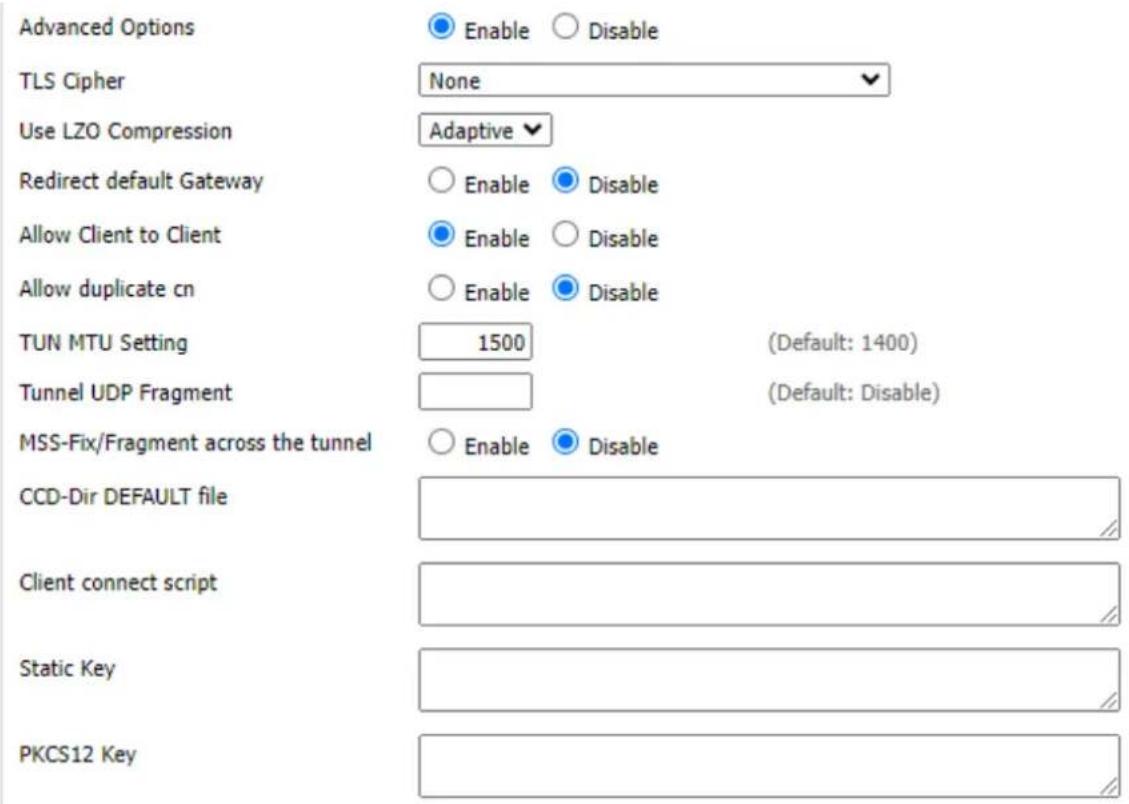
| Object | Description |
| TLS Cipher | TLS (Transport Layer Security) encryption standard supports AES-128/256-CBC-SHA256 and AES-256-GCM-SHA384 |
| Use LZO Compression | Enable or disable use LZO compression for data transfer |
| Redirect Default Gateway | Enable or disable redirect default gateway |
| Allow Client to Client | Enable or disable allow client to client |
| Allow Duplicate cn | Enable or disable allow duplicate cn |
| TUN MTU Setting | Set the value of TUN MTU |
| TCP MSS | MSS of TCP data |
| Client Connect Script | Define some client script by user self |
| Public Server Cert | |
| CA Cert | |
| Private Server Key | |
| DH PEM | |
| Additional Config | |
| TLS Auth Key | |
| Certificate Revoke List | |
| Object | Description |
| Public Server Cert | Server certificate |
| CA Cert | CA certificate |
| Private Server Key | The key selected by the server |
| DH PEM | PEM of the server |
| Additional Config | Additional configurations of the server |
| CCD-Dir DEFAULT file | Other file approaches |
| TLS Auth Key | Authority key of Transport Layer Security |
| Certificate Revoke List | Configure some revoke certificates |
■ OPENVPN Client
OpenVPN Client
Start OpenVPN Client
Server IP/Name
Port
Tunnel Device
Tunnel Protocol
Encryption Cipher
Hash Algorithm
User Pass Authentication
Advanced Options
CA Cert
Public Client Cert
Private Client Key

Enable

Disable
0.0.0.0
1194
(Default: 1194)

V

p ∨

6-128 CBC

4256

Enable

Disable

Enable

Disable
| Object | Description |
| Server IP/Name | IP address or domain name of OPENVPN server |
| Port | Listen port of OPENVPN client |
| Tunnel Device | TUN: Router modeTAP: Bridge mode |
| Tunnel Protocol | UDP and TCP protocol |
| Encryption Cipher | Blowfish CBC, AES-128 CBC, AES-192 CBC, AES-256 CBC,AES512 CBC |
| Hash Algorithm | Hash algorithm provides a method of quick access to data, includingSHA1, SHA256, SHA512, MD5 |

| Object | Description |
| TLS Cipher | TLS (Transport Layer Security) encryption standard supports AES-128/256-CBC-SHA256 and AES-256-GCM-SHA384 |
| Use LZO Compression | Enable or disable use LZO compression for data transfer |
| NAT | Enable or disable NAT through function |
| Bridge TAP to br0 | Enable or disable bridge TAP to br0 |
| Local IP Address | Set IP address of local OPENVPN client |
| TUN MTU Setting | Set MTU value of the tunnel |
| TCP MSS | MSS of TCP data |
| TLS Auth Key | Authority key of Transport Layer Security |
| Additional Config | Additional configurations of OPENVPN server |
| Policy-based Routing | Input some defined routing policy |
CA Cert
Public Client Cert
Private Client Key


| Object | Description |
| CA Cert | CA certificate |
| Public Client Cert | Client certificate |
| Private Client Key | Client key |
4.7.4 IPSEC
IPSec (IP Security) is a generic standardized VPN solution. IPSec must be implemented in the IP stack which is part of the kernel. Since IPSec is a standardized protocol it is compatible to most vendors that implement IPSec. It allows users to have an encrypted network session by standard IKE (Internet Key Exchange). We strongly encourage you to use IPSec only if you need to because of interoperability purposes. When IPSec lifetime is specified, the device can randomly refresh and identify forged IKE's during the IPSec lifetime.
Show IPSEC connection and status of current cellular gateway on IPSEC page.
Connection status and control
| Num | Name | Type | Common Name | status | Action |
| Add |
| Object | Description |
| Name | The name of IPSEC connection |
| Type | The type and function of current IPSEC connection |
| Common Name | Local subnet, local address, opposite end address and opposite end subnet of current connection |
| Status | Connection status:Closed: This connection does not launch a connection request to opposite endNegotiating: This connection launch a request to opposite end, is under negotiating. The connection has not been established yetEstablish: The connection has been established, enabled to use this tunnel |
| Action | The action of this connectionDelete: To delete the connection, also will delete IPSEC if IPSEC has set upEdit: To edit the configure information of this connection, reload this connection to make the configuration effective after editReconnect: This action will remove current tunnel, and re-launch tunnel establish requestEnable: When the connection is enabled, it will launch tunnel establish request when the system reboot or reconnect; otherwise, the connection will not do it |
Click Add to add a new IPSEC connection
To choose IPSEC mode and relevant functions in this part, it currently supports tunnel mode client, tunnel mode server and transfer mode.
Type


This part contains basic address information of the tunnel
Connection
Name
Local WAN Interface
Local Subnet
Local Id
WAN

Enabled
Peer WAN address
Peer subnet
Peer ID



| Object | Description |
| Name | To indicate this connection name |
| Enabled | If enabled, the connection will send tunnel connection request when it is rebooted or reconnected; otherwise, it is disabled. |
| Local WAN Interface | Local address of the tunnel |
| Remote Host Address | IP/domain name of end opposite; this option cannot fill in if tunnel mode server is used. |
| Local Subnet | IPSec local protects subnet and subnet mask, i.e. 192.168.1.0/24; this option cannot fill in if transfer mode is used. |
| Remote Subnet | IPSec opposite end protects subnet and subnet mask, i.e.192.168.7.0/24; this option cannot fill in if transfer mode is used. |
| Local ID | Tunnel local end identification, IP and domain name are available. |
| Remote ID | Tunnel opposite end identification, IP and domain name are available. |
This part contains configure information of connected detection.
Detection

| Object | Description |
| Enable DPD Detection | Enable or disable this function; giving a tick means to enable |
| Time Interval | Set time interval of connected detection (DPD) |
| Timeout | Set the timeout of connected detection |
| Action | Set the action of connected detection |
This part contains relevant setting of IKE, ESP, negotiation mode, etc.
Advanced Settings
Enable advanced settings √
Phase 1
IKE Encryption
IKE Lifetime
AES (256 bit)
0 hours
IKE Integrity
MD5
IKE Grouptype
Group2(1024)
Phase 2
ESP Encryption
ESP Keylife
AES (256 bit)
0 hours
ESP Integrity
SHA2 (512)
ESP Grouptype
NULL
Enable IKEv2
☐ IKE aggressive mode allowed. Avoid if possible (preshared key is transmitted in clear text)!
√ Perfect Forward Secrecy (PFS)
| Object | Description |
| Enable Advanced Settings | Enable to configure 1st and 2nd phase information; Otherwise, it will automatically negotiate according to opposite end. |
| IKE Encryption | IKE-phased encryption mode |
| IKE Integrity | IKE-phased integrity solution |
| IKE Grouptype | DH exchange algorithm |
| IKE Lifetime | Set IKE lifetime, current unit is hour, the default is 0 |
| ESP Encryption | ESP encryption type |
| ESP Integrity | ESP integrity solution |
| ESP Keylife | Set ESP keylife, current unit is hour, the default is 0 |
| IKE Aggressive Mode Allowed | Negotiation mode will adopt aggressive mode if it is ticked; it will be main mode if it is not ticked. |
| Negotiate Payload Compression | Give a tick to enable PFS; to disable PFS, don’t tick it. |
Choose "use shared encryption option" or "certificate authentication option". "shared encryption option" is currently used.
Authentication

Use a Pre-Shared Key:

Generate and use the X.509 certificate
4.7.5 GRE
GRE (Generic Routing Encapsulation) protocol is a network layer protocol (such as IP or IPX) where data packets are encapsulated, so these encapsulated data packets are transmitted using the Generic Routing Encapsulation (GRE) Tunnel technology, which operates at the network layer and employs the Layer Two Tunneling Protocol (L2TP) for Virtual Private Network (VPN) communication.

| Object | Description |
| Number | Switch on/off GRE tunnel app |
| Status | Switch on/off someone's GRE tunnel app |
| Name | GRE tunnel name |
| Through | The GRE packet transmit interface |
| Peer Wan IP Addr | The remote WAN address |
| Peer Subnet | The remote gateway local subnet, e.g. 192.168.1.0/24 |
| Peer Tunnel IP | The remote tunnel IP address |
| Local Tunnel IP | The local tunnel IP address |
| Local Netmask | Netmask of local network |
| Keepalive | Enable or disable GRE Keepalive function |
| Retry times | Retry attempts in case of failure to detect GRE (Generic Routing Encapsulation) keepalive. |
| Interval | The time interval of GRE keepalive packet sent |
| Fail Action | The action will be executed after the failure. |
"View GRE tunnels" keys can view the information of GRE

4.8 Security
4.8.1 Firewall
Firewall enhances network security and uses SPI to check the packets in the network. To use firewall protection, choose to enable otherwise disable. Only enable the SPI firewall or other firewall functions such as filtering proxy, block WAN requests, etc., are used.
■ Firewall Protection
Firewall Protection
SPI Firewall

Enable

Disable
■ Additional Filters
Additional Filters
□ Filter Proxy
Filter Cookies
□ Filter Java Applets
Filter ActiveX
| Object | Description |
| Filter Proxy | Wan proxy server may reduce the security of the gateway. Filtering Proxy will refuse any access to any WAN proxy server. Click the checkbox to enable the function otherwise disable. |
| Filter Cookies | Cookies are the Web data stored in your computer. When you interact with the site, the cookies will be used. Click the checkbox to enable the function otherwise disable. |
| Filter Java Applets | If you decline to use Java, you may encounter difficulties accessing web pages that rely on Java programming. Click the checkbox to enable the function; otherwise, it remains disabled. |
| Filter ActiveX | If you choose not to use ActiveX, you might face limitations in opening web pages that require ActiveX programming. Click the checkbox to enable the function; otherwise, it will remain disabled. |
■ Prevent WAN Request
Block WAN Requests
√ Block Anonymous WAN Requests (ping)
√ Filter IDENT (Port 113)
√ Block WAN SNMP access
| Object | Description |
| Block Anonymous WAN Requests (ping) | By checking the "Block Anonymous WAN Requests (ping)" box, you can activate this feature and prevent your network from being pinged or detected by other internet users. This adds an extra layer of security, making it more challenging for unauthorized access to your network.The default setting for this feature is enabled; choose to disable it if you wish to allow anonymous internet requests. |
| Filter Cookies | Enabling this feature can prevent port 113 from being scanned from outside. Click the checkbox to enable the function; otherwise, leave it disabled. |
| Filter Java Applets | This feature prevents the SNMP connection requests from the WAN. |
■ Impede WAN DoS/Bruteforce
Impede WAN DoS/Bruteforce
□ Limit SSH Access
□ Limit Telnet Access
□ Limit PPTP Server Access
□ Limit L2TP Server Access
| Object | Description |
| Limit SSH Access | This feature restricts access requests from the WAN via SSH, allowing a maximum of two connection requests per minute from the same IP.Any additional access requests will be automatically dropped. |
| Limit Telnet Access | This feature restricts access requests from the WAN through Telnet, allowing up to two connection requests per minute from the same IP.Any additional access requests will be automatically dropped. |
| Limit PPTP Server Access | When establishing a PPTP Server in the cellular gateway, this feature limits access requests from the WAN via SSH, allowing a maximum of two connection requests per minute from the same IP. Any new access request beyond this limit will be automatically dropped. |
| Limit L2TP Server Access | When configuring an L2TP Server in the cellular gateway, this feature restricts access requests from the WAN via SSH. It allows a maximum of two connection requests per minute from the same IP, automatically dropping any new access requests beyond this limit. |
Log Management
The cellular gateway can keep logs of all incoming or outgoing traffic for your Internet connection. To keep activity logs, select Enable. To stop logging, select Disable. When selecting enable, the following page will appear.
Log
Log
Log Level

Enable

Disable
Low

Options
Dropped
Rejected
Accepted
Disable
Disable ▼
Disable ▼
Incoming Log
Outgoing Log
| Object | Description |
| Log Level | Set this to the required log level. Set Log Level higher to log more actions. |
| Options | When you choose to enable this feature, the corresponding connection will be logged in the journal; when disabled, the connections will not be recorded. |
| Incoming Log | To see a temporary log of the cellular gateway's most recent incoming traffic, click the Incoming Log button. |
| Outgoing Log | To see a temporary log of the cellular gateway's most recent outgoing traffic, click the Outgoing Log button. |


After making the necessary adjustments, click the "Save Settings" button to save your changes. Alternatively, click the "Cancel Changes" button to discard any modifications that have not been saved.
4.9 Access Restrictions
4.9.1 WAN Access
This screen allows you to block or allow specific kinds of Internet usage. You can set up Internet access policies for specific PCs and set up filters by using network port numbers. This feature allows you to customize up to 10 different Internet Access Policies for particular PCs.





| PCs | The part is used to edit client list; the strategy is only effective for the PC in the list. |
| Days | Choose the day of the week you would like your policy to be applied. |
| Times | Enter the time of the day you would like your policy to be applied. |
| Website Blocked by URL Address | You can block access to certain websites by entering their URL. |
| Website Blocked by Keyword | You can block access to certain website by the keywords contained in their webpage. |
After clinking "Edit List of Clients", it would pop-up new window, as shown below:
List of clients
Enter the IP Address of the clients
| IP 01 | 192.168.1 | 50 |
| IP 02 | 192.168.1 | 0 |
| IP 03 | 192.168.1 | 0 |
| IP 04 | 192.168.1 | 0 |
| IP 05 | 192.168.1 | 0 |
| IP 06 | 192.168.1 | 0 |
Enter the IP Range of the clients
| IP Range 01 | 192. | 168. | 100. | 1~ | 192 | 168 | 100 | 100 |
| IP Range 02 | 0. | 0. | 0. | 0~ | 0 | 0 | 0 | 0 |
Save
Apply Settings
Cancel Changes
Close
4.9.2 MAC Filtering
MAC filtering is a security feature used in networks to control device access based on their unique Media Access Control (MAC) addresses. By specifying allowed MAC addresses, the filter permits only authorized devices to connect, enhancing network security by preventing unauthorized access and protecting against potential intruders or unapproved devices.
Mac Filter Setting

| Object | Description |
| Discard packets that conform to the following rules | Only discard the matching URL address in the list. |
| Accept only the data packets that conform to the following rules | Receive only with custom rules of network address; discard all other URL addresses. |
Set up Internet access policy
- Select the policy number (1-10) in the drop-down menu.
- For this policy to be enabled, click the radio button next to "Enable"
- Enter a name in the Policy Name field.
-
Click the Edit List of PCs button.
-
On the List of PC screen, specify PCs by IP address or MAC address. Enter the appropriate IP addresses into the IP fields. If you have a range of IP addresses to filter, complete the appropriate IP Range fields. Enter the appropriate MAC addresses in the MAC fields.
-
Click the Apply button to save your changes. Click the Cancel button to cancel your unsaved changes. Click the Close button to return to the Filters screen.
-
If you want to block the listed PCs from Internet access during the designated days and time, then keep the default setting, Deny. If you want the listed PCs to have Internet filtered during the designated days and time, then click the radio button next to Filter.
-
Set the days when access will be filtered. Select Everyday or the appropriate days of the week.
-
Set the time when access will be filtered. Select 24 Hours, or check the box next to From and use the drop-down boxes to designate a specific time period.
-
Click the Add to Policy button to save your changes and activate it.
-
To create or edit additional policies, repeat steps 1-9.
-
To delete an Internet Access Policy, select the policy number, and click the Delete button.
Note:
-
The default factory value of policy rules is "filtered". If the user chooses the default policy rules for "refuse", and editing strategies to save or directly to save the settings. If the strategy edited is the first, it will be automatically saved into the second, if not the first; keep the original number.
-
Turning off the power of the cellular gateway or rebooting the cellular gateway can cause a temporary failure. After the failure of the cellular gateway, if cannot automatically synchronized NTP time server, you need to recalibrate to ensure the correct implementation of the relevant period control function.
4.9.3 Packet Filtering
Packet filtering is a network security method that selectively allows or blocks data packets based on predefined criteria such as source or destination IP addresses, ports, or protocols. It helps secure networks by controlling the flow of data, preventing unauthorized access, and mitigating potential threats through the analysis and filtering of network packets.

| Object | Description |
| Enable Packet Filter | Enable or disable “packet filter” function |
| Policy | The filter rule’s policy is that you can choose the following optionsDiscard The Following--Discard packets conform to the following rules, accept all other packetsOnly Accept The Following--Accept only the data packets that conform to the following rules. Discard all other packets |
| Add Filter Rule Dir(Direction) | Input: Packet from WAN to LANOutput: Packet from LAN to WAN |
| Interface | The interface will be used by the function. |
| Pro (Protocol) | Packet protocol type |
| Sports (Source Ports) | Packet's source port |
| DPorts (Destination Ports) | Packet's destination port |
| Source IP | Packet's source IP address |
| Destination IP | Packet's destination IP address |
Note: "Source Port", "Destination Port", "Source IP", and "Destination IP" could not be all empty; you'll have to input at least one of these four parameters.
4.10 NAT
4.10.1 Port Forwarding
Port Forwarding allows you to set up public services on your network, such as web servers, ftp servers, e-mail servers, or other specialized Internet applications. Specialized Internet applications are any applications that use Internet access to perform functions such as videoconferencing or online gaming. When users send this type of request to your network via the Internet, the cellular gateway will forward those requests to the appropriate PC. If you want to forward a whole range of ports, see Port Range Forwarding.
Forwards

| Object | Description |
| Application | Enter the name of the application in the field provided. |
| Protocol | Chose the right protocol TCP, UDP or Both. Set this to what the application requires. |
| Source Net | Forward only if sender matches this IP/net (like 192.168.1.0/24) |
| Port from | Enter the number of the external port (the port number seen by users on the Internet). |
| IP Address | Enter the IP Address of the PC running the application. |
| Port to | Enter the number of the internal port (the port number is used by the application). |
| Enable | Click the Enable checkbox to enable port forwarding for the application. |
Check all values and click Save Settings to save your settings. Click the Cancel changes button to cancel your unsaved changes.
4.10.2 Port Range Forwarding
Port Range Forwarding allows you to set up public services on your network, such as Web servers, ftp servers, e-mail servers, or other specialized Internet applications. Specialized Internet applications are any applications that use Internet access to perform functions such as videoconferencing or online gaming. When users send this type of request to your network via the Internet, the cellular gateway will forward those requests to the appropriate PC. If you only want to forward a single port, see Port Forwarding.
Port Range Forward
Forwards
| Application | Start | End | Protocol | IP Address | Enable |
| web-tftp | 800 | 8100 | Both | 192.168.1.16 | |
| game | 9000 | 10000 | Both | 192.168.1.16 |
Forwards
| Delete | Num | Application | Start | End | Protocol | IP Address | Enable |
| □ | 1 | frp | 21 | 21 | Both▼ | 192.168.100.21 | |
| □ | 2 | 0 | 0 | Both▼ | 0.0.0.0 | □ |
| Object | Description |
| Application | Enter the name of the application in the field provided. |
| Start | Enter the number of the first port of the range you want to see by users on the Internet and forwarded to your PC. |
| End | Enter the number of the last port of the range you want to see by users on the Internet and forwarded to your PC. |
| Protocol | Choose the right protocol: TCP, UDP or both. Set this to what the application requires. |
| IP Address | Enter the IP Address of the PC running the application. |
| Enable | Click the checkbox to enable port forwarding for the application. |
Check all values and click Save Settings to save your settings. Click the Cancel changes button to cancel your unsaved changes.
4.10.3 DMZ
The DMZ (Demilitarized Zone) hosting feature allows one local user to be exposed to the Internet for use of a special-purpose service such as Internet gaming or video conferencing. DMZ hosting forwards all the ports at the same time to one PC.
DMZ
Use DMZ
DMZ Host IP Address

Enable

Disable
192.168.1.

| Object | Description |
| DMZ Host IP Address | To expose one PC to the Internet, select Enable and enter the computer's IP address in the DMZ Host IP Address field. To disable the DMZ, keep the default setting Disabled. |
Check all values and click Save Settings to save your settings. Click the Cancel changes button to cancel your unsaved changes.
4.11 QoS Setting
4.11.1 Basic
Bandwidth management prioritizes the traffic on your cellular gateway. Interactive traffic (telephony, browsing, telnet, etc.) gets priority and bulk traffic (file transfer, P2P) gets low priority. The main goal is to allow both types to live side by side without unimportant traffic disturbing more critical things. All of this is automatic.
QoS allows control of the bandwidth allocation to different services, netmasks, MAC addresses and the four LAN ports.
QoS
Main WAN QoS Settings
Start QoS
Port
Packet Scheduler
Uplink (kbps)
Downlink (kbps)

Enable

Disable
WAN
HTB
0
0
Bkup WAN QoS Settings
Start QoS
Port
Packet Scheduler
Uplink (kbps)
Downlink (kbps)

Enable

Disable
WAN
HTB
0
0
| Object | Description |
| Uplink (kbps) | In order to use bandwidth management (QoS) you must enter bandwidth values for your uplink. These are generally 80% to 90% of your maximum bandwidth. |
| Downlink (kbps) | In order to use bandwidth management (QoS) you must enter bandwidth values for your downlink. These are generally 80% to 90% of your maximum bandwidth. |
■ HTB Setting
HTB Prio Setting Uplink
| Priority | Band range | Band value | |
| Premium | 75% - | 75% | Main WAN : 0 -- 0 kbpsBkup WAN : 0 -- 0 kbps |
| Express | 15% - | 15% | Main WAN : 0 -- 0 kbpsBkup WAN : 0 -- 0 kbps |
| Standard | 10% - | 10% | Main WAN : 0 -- 0 kbpsBkup WAN : 0 -- 0 kbps |
| Bulk | 1% - | 1% | Main WAN : 0 -- 0 kbpsBkup WAN : 0 -- 0 kbps |
HTB Prio Setting Downlink
| Priority | Band range | Band value | ||
| Premium | 75% - | 75% | Main WAN : 0 -- 0 kbpsBkup WAN : 0 -- 0 kbps | |
| Express | 15% - | 15% | Main WAN : 0 -- 0 kbpsBkup WAN : 0 -- 0 kbps | |
| Standard | 10% - | 10% | Main WAN : 0 -- 0 kbpsBkup WAN : 0 -- 0 kbps | |
| Bulk | 1% - | 1% | Main WAN : 0 -- 0 kbpsBkup WAN : 0 -- 0 kbps | |
4.11.2 Classify
Netmask Priority
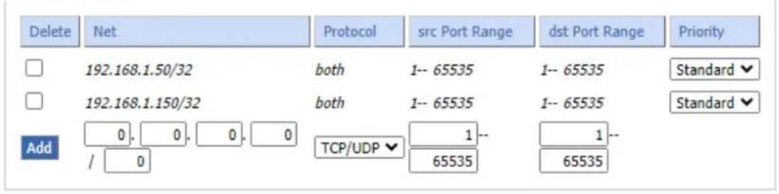
MAC Priority
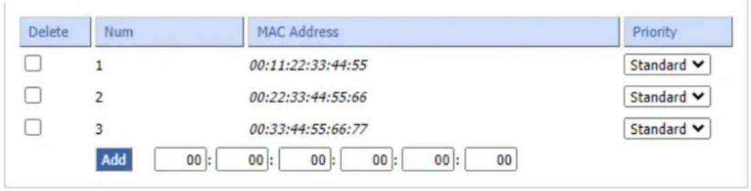
Netmask Priority: You may specify priority for all traffic from a given IP address or IP Range.
MAC Priority: You may specify priority for all traffic from a device on your network by giving the device a specifying priority and entering its MAC address
Check all values and click Save Settings to save your settings. Click the Cancel changes button to cancel your unsaved changes.
4.12 Applications
4.12.1 Serial Applications
There is a console port on cellular gateway. Normally, this port is used to debug the cellular gateway. This port can also be used as a serial port. The cellular gateway has embedded a serial to TCP program. The data sent to the serial port is encapsulated by TCP/IP protocol stack and then is sent to the destination server. This function can work as a DTU (Data Terminal Unit).

| Object | Description |
| Baudrate | Baud rate indicates the number of bytes per second transported by device, commonly used baud rate is 115200, 57600, 38400 or 192000. |
| Databit | The data bits can be 4, 5, 6, 7 and 8 that constitute a character. The ASCII code is usually used, starting from the most significant bit. |
| Stopbit | It marks the end of a character data. It is a high level of 1, 1.5 and 2. |
| Parity | Use a set of data to check the data error. |
| Flow Control | Including the hardware part and software part in two ways. |
| Enable Serial TCP Function | Enable the serial to TCP function |
| Protocol Type | The protocol type to transmit data.UDP (DTU): Data transmitted with UDP protocol, work as an IP modem device with application protocol and heartbeat mechanism.Pure UDP – Data transmitted with standard UDP protocol.TCP (DTU): Data transmitted with TCP protocol, work as an IP modem device with application protocol and heartbeat mechanism.Pure TCP: Data transmitted with standard TCP protocol; cellular gateway is the client.TCP Server: Data transmitted with standard TCP protocol; cellular gateway is the server.TCST: Data transmitted with TCP protocol, using a custom data |
| Server Address | The data service center's IP address or domain name. |
| Server Port | The data service center's listening port. |
| Device ID | The ID of the cellular gateway. |
| Device Number | The phone number of the cellular gateway. |
| Heartbeat Interval | The time interval to send heartbeat packet. This item is valid only when you choose UDP (DTU) or TCP (DTU) protocol type. |
| TCP Server Listen Port | This item is valid when Protocol Type is “TCP Server”. |
| Custom Heartbeat Packet | This item is valid when Protocol Type is “TCST”. |
| Custom Registration Packets | This item is valid when Protocol Type is “TCST”. |
3.5 mm Terminal Interface Definition:
Using 6-pin terminal 3.5 mm of the interface, power, and function of RS232 and RS485. Specific definitions are as follows:
| 6-pin 3.5 mm Terminal Interface Definition | |||
| Number | Definition | Signal Description | Extended Function |
| 1 | VCC | Positive device's power supply terminal | |
| 2 | GND | Negative device's power supply terminal | RS232 common ground |
| 3 | TX | RS232 transmitting end | |
| 4 | RX | RS232 receiving end | |
| 5 | B | RS485 B end | |
| 6 | A | RS485 A end | |
4.13 Administration
4.13.1 Management
The Management screen allows you to change the cellular gateway settings. On this page, you will find most of the configurable items of the cellular gateway code.
Router Password
Router Username
Router Password
Re-enter to confirm

The new password must not exceed 32 characters in length and must not include any spaces. Enter the new password a second time to confirm it.
Note: Default username is admin. It is strongly recommended that you change the factory default password of the cellular gateway, which is admin. All users who try to access the cellular gateway Web-based utility or setup wizard will be prompted for the cellular gateway password.
Web Access
This feature allows you to manage the cellular gateway using either HTTP protocol or the HTTPS protocol. If you choose to disable this feature, a manual reboot will be required. You can also activate or inactivate the cellular gateway information Web page. It's now possible to protect the password on this page.
Web Access
Protocol
Auto-Refresh (in seconds)
Enable Info Site
Info Site Password Protection

HTTP

HTTPS


Enable

Disable

Enabled
| Object | Description |
| Protocol | This feature allows you to manage the cellular gateway using either HTTP protocol or the HTTPS protocol. |
| Auto-Refresh | Enable or disable the login system information page. |
| Enable Info Site | Enable or disable the login system information page |
| Info Site Password Protection | Enable or disable the password protection feature of the system information page |
■ Remote Access
This feature allows you to manage the cellular gateway from a remote location, via the Internet. To disable this feature, keep the default setting disabled. To enable this feature, select Enable, and use the specified port (default is 8088) on your PC to remotely manage the cellular gateway. You must also change the cellular gateway default password to one of your own, if you haven't already.
To remotely manage the cellular gateway, enter https://xxx.xxx.xxx.xxx:8088 (the x's represent the cellular gateway Internet IP address, and 8088 represents the specified port) in your web browser's address field. You will be asked for the cellular gateway password.
If you use https you need to specify the url as https://xxx.xxx.xxx.xxx:8088 (not all firmwares do support this without rebuilding with SSL support).
Remote Access
Web GUI Management
Remote Protocol
Web GUI Port
Local Web GUI Port
Remote SSH
Remote SSH Port
Telnet Management

Enable

Disable

8088
80

Enable

Disable

22

Enable

Disable
(Default: 8088, Range: 1 - 65535)
(Default: 80, Range: 1 - 65535)
(Default: 22, Range: 1 - 65535)
| Object | Description |
| SSH Management | You can also enable SSH to remotely access the cellular gateway by Secure Shell. Note that SSH daemon needs to be enabled in Services page. |
| Telnet Management | Enable or disable remote Telnet function |
Note: If the Remote Router Access feature is enabled, anyone who knows the cellular gateway's Internet IP address and password will be able to alter the cellular gateway's settings.
Cron
The cron subsystem schedules execution of Linux commands. You'll need to use the command line or startup scripts to use this.

■ Remote Management
Web remote management refers to the technology enabling the remote monitoring, configuration, troubleshooting, and updating of devices or systems through a web interface. It allows administrators to oversee and control distant equipment, facilitating real-time monitoring, centralized configuration, and efficient issue resolution.
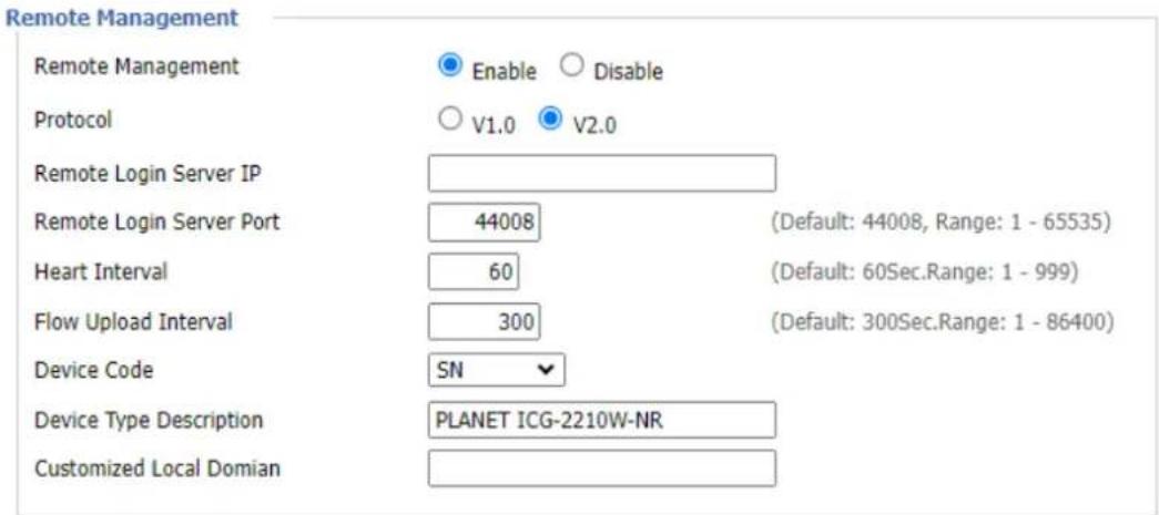
4.13.2 Keep Alive
The user can schedule regular reboots for the cellular gateway.
Schedule Reboot
Schedule Reboot
Interval (in seconds)
At a set Time

Enable

Disable

3600


| Object | Description |
| Interval (in seconds) | Regularly reboot the DUT at a specific time |
| At a set Time | At a specific date time each week or every day |
Note:
For date-based reboots, Cron must be activated. See Management for Cron activation.
4.13.3 Commands
User can run command lines directly via the Web interface.
Command Shell
Commands
Run Commands
Save Startup
Save Shutdown
Save Firewall
Save Custom Script
| Object | Description |
| Run Command | You can run command lines via the Web interface. Fill in the text area with your command and click Run Commands to submit. |
| Startup | You can save some command lines to be executed at startup's cellular gateway. Fill in the text area with commands (only one command by row) and click Save Startup. |
| Shutdown | You can save some command lines to be executed at shutdown's cellular gateway. Fill in the text area with commands (only one command by row) and click Save Shutdown. |
| Firewall | Each time the firewall is started, it can run some custom iptables instructions. |
| Custom Script | Custom script is stored in /tmp/custom.sh file. You can run it manually or use cron to call it. Fill in the text area with script's instructions (only one command by row) and click Save Custom Script. |
4.13.4 Factory Defaults
This page provides "return all configuration settings to the original settings".
Reset router settings
Any settings you have saved will be lost when the default settings are restored. After restoring the cellular gateway, it is accessible under the default IP address 192.168.1.1 and the default password is admin.
4.13.5 Firmware Upgrade
This page provides the firmware upgrade function
Firmware Upgrade
Please select a file to upgrade
Choose file No file chosen
WARNING
Upgrading firmware may take a few minutes. Do not turn off the power or press the reset button!
Upgrade
Note:
When you upgrade the firmware of cellular gateway, you could lose its configuration settings, so make sure you write down the cellular gateway settings before you upgrade its firmware.
Note:
Upgrading firmware may take a few minutes.
Do not turn off the power or press the reset button!
4.13.6 Backup
Backup Configuration
Backup Settings
Click the "Backup" button to download the configuration backup file to your computer.
Restore Configuration
Restore Settings
Please select a file to restore
Choose file
No file chosen
WARNING
Only upload files backed up using this firmware and from the same model of router. Do not upload any files that were not created by this interface!
Backup
Restore
| Object | Description |
| Backup Settings | You may back up your current configuration in case you need to reset the cellular gateway back to its factory default settings. Click the Backup button to back up your current configuration. |
| Restore Settings | Click the Browse... button to look for a configuration file that is currently saved on your PC. Click the Restore button to overwrite all current configurations with the ones in the configuration file. |
Note:
Only restore configurations with files backed up using the same firmware and the same model of cellular gateway.
4.14 Status
4.14.1 Router
The system status of the cellular gateway.
System
| Router Name | PLANET Cellular Wireless Gateway |
| Router Model | ICG-2210W-NR |
| Firmware Version | ICG-2210W-NR v1.0 (Dec 19 2023 18:36:09) std |
| MAC Address | A8:F7:E0:39:6B:A0 |
| Host Name | |
| WAN Domain Name | |
| LAN Domain Name | |
| Current Time | Fri, 19 Jan 2024 09:54:30 |
| Uptime | 4 min |
| Object | Description |
| Router Name | Name of the cellular gateway that can be changed |
| Router Model | Model of the cellular gateway that cannot be changed |
| Firmware Version | software version information |
| MAC Address | MAC address of WAN that can be changed |
| Host Name | Host name of the cellular gateway that can be changed |
| WAN Domain Name | Domain name of WAN that can be changed |
| LAN Domain Name | Domain name of LAN that cannot be changed |
| Current Time | Local time of the system |
| Uptime | Operating uptime if the system is powered on |
Memory
| Total Available | 505960 kB / 524288 kB | 97% |
| Free | 430336 kB / 505960 kB | 85% |
| Used | 75624 kB / 505960 kB | 15% |
| Buffers | 4992 kB / 75624 kB | 7% |
| Cached | 13060 kB / 75624 kB | 17% |
| Active | 11404 kB / 75624 kB | 15% |
| Inactive | 9756 kB / 75624 kB | 13% |
| Object | Description |
| Total Available | The total availability of RAM |
| Free | The cellular gateway will reboot if the memory is less than 500kB. |
| Used | The total availability of memory minus free memory |
| Buffers | Used memory for buffers |
| Cached | The memory used by high-speed cache memory |
| Active | Active use of buffer or cache memory |
| Inactive | Not often used in a buffer or cache memory |
Network
| IP Filter Max Connections | 16384 | |
| Active IP Connections | 89 | 1% |
| Object | Description |
| IP Filter Maximum Ports | Preset is 4096, available to remanage |
| Active IP Connections | Real-time monitoring of active IP connections of the system, |
Active IP Connections Table
Active IP Connections
95
| No. | Protocol | Timeout (s) | Source Address | Remote Address | Service Name | State |
| 1 TCP | 98 | 192.168.1.150 | 192.168.1.1 | 80 TIME_WAIT | ||
| 2 TCP | 119 | 192.168.1.150 | 192.168.1.1 | 80 TIME_WAIT | ||
| 3 TCP | 17 | 192.168.1.150 | 192.168.1.1 | 80 TIME_WAIT | ||
| 4 TCP | 67 | 192.168.1.150 | 192.168.1.1 | 80 TIME_WAIT | ||
| 5 UDP | 32 | 192.168.0.25 | 192.168.0.254 | 53 UNREPLIED | ||
| 6 TCP | 2 | 192.168.1.150 | 192.168.1.1 | 80 TIME_WAIT | ||
| 7 Unknown | 512 | 192.168.1.1 | 224.0.0.2 | UNREPLIED | ||
| 8 TCP | 38 | 192.168.1.150 | 192.168.1.1 | 80 TIME_WAIT | ||
| 9 TCP | 49 | 192.168.1.150 | 192.168.1.1 | 80 TIME_WAIT | ||
| 10 TCP | 3571 | 192.168.1.150 | 20.90.152.133 | 443 ESTABLISHED | ||
| 11 TCP | 58 | 192.168.1.150 | 192.168.1.1 | 80 TIME_WAIT | ||
| 12 UDP | 5 | 192.168.1.150 | 192.168.1.1 | 53 UNREPLIED | ||
| 13 TCP | 49 | 192.168.1.150 | 192.168.1.1 | 80 TIME_WAIT | ||
| 14 TCP | 101 | 192.168.1.150 | 192.168.1.1 | 80 TIME_WAIT | ||
| 15 TCP | 95 | 192.168.1.150 | 192.168.1.1 | 80 TIME_WAIT | ||
| 16 TCP | 17 | 192.168.1.150 | 192.168.1.1 | 80 TIME_WAIT | ||
| 17 TCP | 64 | 192.168.1.150 | 192.168.1.1 | 80 TIME_WAIT | ||
| 18 Unknown | 509 | 192.168.1.1 | 224.0.0.1 | UNREPLIED | ||
| 19 TCP | 49 | 192.168.1.150 | 192.168.1.1 | 80 TIME_WAIT | ||
| 20 TCP | 2 | 192.168.1.150 | 192.168.1.1 | 80 TIME_WAIT | ||
| 21 UDP | 15 | 192.168.1.150 | 192.168.1.1 | 53 UNREPLIED | ||
| 22 TCP | 73 | 192.168.1.150 | 192.168.1.1 | 80 TIME_WAIT | ||
| 23 TCP | 70 | 192.168.1.150 | 192.168.1.1 | 80 TIME_WAIT | ||
| 24 TCP | 61 | 192.168.1.150 | 192.168.1.1 | 80 TIME_WAIT | ||
| 25 UDP | 15 | 192.168.0.25 | 192.168.0.254 | 53 UNREPLIED | ||
| 26 TCP | 40 | 192.168.1.150 | 192.168.1.1 | 80 TIME_WAIT |
| Object | Description |
| Active IP Connections | Total active IP connections |
| Protocol | Connection protocol |
| Timeouts | Connection timeouts, unit is second |
| Source Address | Source IP address |
| Remote Address | Remote IP address |
| Service Name | Connecting service port |
| Status | Displayed status |
4.14.2 WAN
The internet connection status of the cellular gateway.
Configuration Type
| Connection Type | Automatic Configuration - DHCP |
| Connection Uptime | 0:00:30 |
| IP Address | 25.18.247.159 |
| IPV6 Address | 2001:b400:e158:98f:231:38ff:fe38:3436 |
| Subnet Mask | 255.255.255.192 |
| Gateway | 25.18.247.160 |
| DNS 1 | 168.95.1.1 |
| DNS 2 | 168.95.192.1 |
| DNS 3 |
| Object | Description |
| Connection Type | Disabled, static IP, automatic configurations -- DHCP, PPPOE, PPTP, L2TP, 3G/UMTS,DHCP-4G/5G |
| Connection Uptime | Connecting uptime; if disconnected, it will display “Not available”. |
| IP Address | IP address of cellular gateway (WAN) |
| Subnet Mask | Subnet mask of cellular gateway (WAN) |
| Gateway | The gateway of cellular gateway (WAN) |
| DNS1, DNS2, DNS3 | DNS1/DNS2/DNS3 of Cellular gateway (WAN) |
| -89 dBm | |
| 5G Signal Status | |
| 4G/3G Signal Status | -91 dBm |
| Network | FDD LTE |
| BAND | LTE BAND 7+NR N78 |
| Object | Description |
| 5G Signal Status | Signal intensity of the module in 5G NR way |
| 4G/3GSignal Status | Signal intensity of the module in LTE/3G/UMTS way |
| Network | IP address of cellular gateway (WAN) |
| BAND | Subnet mask of cellular gateway (WAN) |
Total Traffic
| Incoming (MBytes) | 9 |
| Outgoing (MBytes) | 4 |
Traffic by Month

Previous Month Next Month
| Object | Description |
| Total Flow | Statistics on the flow from the last power-off until now, including |
| Monthly Flow | The flow of a month; unit is MB |
| Last Month | The flow of last month |
| Next Month | The flow of next month |
Data Administration
Backup
Restore
Delete
| Object | Description |
| Backup | Backup data administration |
| Restore | Restored data administration |
| Delete | Deleted data administration |
4.14.3 LAN
The Local network status of the cellular gateway.
LAN Status
| MAC Address | A8:F7:E0:39:6B:9F |
| IP Address | 192.168.1.1 |
| IPV6 Address | |
| Subnet Mask | 255.255.255.0 |
| Gateway | 192.168.1.254 |
| Local DNS | 0.0.0.0 |
| Object | Description |
| MAC Address | MAC Address of the LAN Ethernet port |
| IP Address | IP Address of the LAN port |
| Subnet Mask | Subnet Mask of the LAN port |
| Gateway | Gateway of the LAN port |
| Local DNS | DNS of the LAN port |
Active Clients
| Host Name | IP Address | MAC Address | Conn. Count | Ratio [16384] |
| ENM-NB-KIN | 192.168.1.150 | 04:42:1a:b9:01:44 | 80 | 0% |
| Object | Description |
| Host Name | Host name of LAN client |
| IP Address | IP address of the client |
| MAC Address | MAC address of the client |
| Conn. Count | Connection count caused by the client |
| Ratio | The ratio of 4096 connection |
DHCP Status
| DHCP Server | Enabled |
| DHCP Daemon | DNSMasq |
| Start IP Address | 192.168.1.100 |
| End IP Address | 192.168.1.199 |
| Client Lease Time | 1440 minutes |
DHCP Clients
| Host Name | IP Address | MAC Address | Client Lease Time | Delete |
| ENM-NB-KIN | 192.168.1.150 | 04:42:1A:B9:01:44 | 1 day 00:00:00 |
| Object | Description |
| DNCP Server | Enable or disable the cellular gateway that works as a DHCP server |
| DHCP Daemon | The agreement allocated using DHCP including DNSMasq and uDHCPd Starting IP |
| Address | The starting IP Address of the DHCP server's Address pool |
| Ending IP Address | The ending IP Address of the DHCP server's Address pool |
DHCP Clients
| Host Name | IP Address | MAC Address | Client Lease Time | Delete |
| DESKTOP-P45PKJ3 | 192.168.1.169 | A0:A3:F0:49:96:2F | 1 day 00:00:00 | |
| ENM-NB-KIN | 192.168.1.150 | 04:42:1A:B9:01:44 | 1 day 00:00:00 | |
| * | 192.168.1.119 | 90:E8:68:53:3D:9F | 1 day 00:00:00 |
| Object | Description |
| Client Lease Time | The lease time of DHCP client |
| Host Name | Host name of LAN client |
| IP Address | IP address of the client |
| MAC Address | MAC address of the client |
| Expires | The expiry the client rents the IP address |
4.14.4 Wireless
The wireless status of the cellular gateway.
2.4G Wireless Status
| MAC Address | A8:F7:E0:39:6B:A1 |
| Radio | Radio is On |
| Mode | AP |
| Network | Mixed |
| SSID | PLANET_ICG-2210W-NR_2.4G |
| Channel | 5 (2.432 GHz) |
| TX Power | 20 dBm |
| Rate | 200 Mb/s |
| Encryption - Interface wI0 | Enabled, WPA2 Personal Mixed |
5.8G Wireless Status
| MAC Address | A8:F7:E0:39:6B:A2 |
| Radio | Radio is On |
| Mode | AP |
| Network | ac |
| SSID | PLANET_ICG-2210W-NR_5G |
| Channel | 149 (5.745 GHz) |
| TX Power | 18 dBm |
| Rate | 433.3 Mb/s |
| Encryption - Interface wl0_5G | Enabled, WPA2 Personal Mixed |
| Object | Description |
| MAC Address | MAC address of wireless client |
| Radio | Display whether radio is on or not |
| Mode | Wireless mode |
| Network | Wireless network mode |
| SSID | Wireless network name |
| Channel | Wireless network channel |
| TX Power | Reflected power of wireless network |
| Rate | Reflected rate of wireless network |
| Encryption-Interface | Enable or disable Encryption-Interface wI0 |
2.4G Wireless Packet Info
| Received (RX) | 60067 OK, no error | 100% |
| Transmitted (TX) | 12378 OK, no error | 100% |
5.8G Wireless Packet Info
| Received (RX) | 32809 OK, no error | 100% |
| Transmitted (TX) | 10056 OK, no error | 100% |
| Object | Description |
| Received (RX) | Received data packet |
| Transmitted (TX) | Transmitted data packet |
2.4G Wireless Nodes
Clients
| MAC Address | Interface | Uptime | TX Rate | RX Rate | Rssi | Min Rssi | Max Rssi |
| a0:a3:f0:49:96:2f | ath0 | 00:01:31 | 200M | 180M | 51 | 45 | 59 |
5.8G Wireless Nodes
Clients
| MAC Address | Interface | Uptime | TX Rate | RX Rate | Rssi | Min Rssi | Max Rssi |
| 90:e8:68:53:3d:9f | ath1 | 00:06:04 | 433M | 40M | 31 | 3 | 32 |
| Object | Description |
| MAC Address | MAC address of wireless client |
| Interface | Interface of wireless client |
| Uptime | Connecting uptime of wireless client |
| TX Rate | Transmit rate of wireless client |
| RX Rate | Receive rate of wireless client |
| Signal | The signal of wireless client |
| Noise | The noise of wireless client |
| SNR | The signal to noise ratio of wireless client |
| Signal Quality | Signal quality of wireless client |
Neighbor's Wireless Networks
| SSID | Mode | MAC Address | Channel | Rssi | Noise | beacon | Open | dtim | Rate | Join Site |
| WAC510 | AP | 80:CC:9C:A9:49:20 | 1 | -56 | -95 | 0 | on | 2 | Join | |
| PLANET_6F_AP | AP | A8:F7:E0:34:31:32 | 1 | -67 | -95 | 0 | on | 1 | Join | |
| 6F LAB | AP | A8:F7:E0:B2:31:FA | 1 | -61 | -95 | 0 | on | 2 | Join | |
| WDAP-C1800AX-2.4G | AP | B2:F7:E0:B2:31:FA | 1 | -62 | -95 | 0 | on | 2 | Join | |
| U6Lite | AP | D0:21:F9:ED:FE:09 | 6 | -57 | -95 | 0 | on | 3 | Join | |
| PLANET_WDAP-C3000AX_2.4G | AP | A8:F7:E0:00:33:03 | 6 | -48 | -95 | 0 | on | 2 | Join | |
| ENM-2.4G | AP | 44:18:47:01:00:10 | 11 | -53 | -95 | 0 | on | 1 | Join | |
| ENM_2.4G_TEST | AP | 00:E0:61:60:9F:A6 | 11 | -56 | -95 | 0 | on | 1 | Join | |
| KINL | AP | A8:F7:E0:A1:B2:C9 | 149 | -55 | -95 | 0 | on | 2 | Join | |
| PLANET_6F_AP(5G) | AP | A8:F7:E0:34:31:33 | 149 | -78 | -95 | 0 | on | 1 | Join |
Refresh Close
| Object | Description |
| SSID | The name of wireless network nearby |
| Mode | Operating mode of wireless network nearby |
| MAC Address | MAC address of the wireless nearby |
| Channel | The channel of the wireless nearby |
| Rssi | Signal intensity of the wireless nearby |
| Noise | The noise of the wireless nearby |
| Beacon | Signal beacon of the wireless nearby |
| Open | The wireless nearby is open or not |
| Dtim | Delivering traffic indication message of the wireless nearby |
| Rate | Speed rate of the wireless nearby |
| Join Site | Click to join wireless network nearby |
4.14.5 Bandwidth
The Bandwidth Monitoring of LAN Graph and WAN Graph
Abscissa axis: Time
Vertical axis: Speed rate
Bandwidth Monitoring - LAN

Bandwidth Monitoring - WAN

The Bandwidth Monitoring of Wireless Graph
Abscissa axis: Time
Vertical axis: Speed rate
Bandwidth Monitoring - Wireless (wifi0)
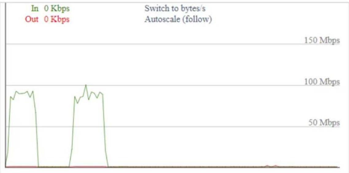
Bandwidth Monitoring - Wireless (wifi1)

4.14.6 Sys Info
Router
| Router Name | PLANET Cellular Wireless |
| Gateway | |
| Router Model | ICG-2210W-NR |
| LAN MAC | A8:F7:E0:39:6B:9F |
| WAN MAC | A8:F7:E0:39:6B:A0 |
| Wireless MAC | A8:F7:E0:39:6B:A1 |
| WAN IP | 25.15.167.100 |
| BKUP WAN IP | 192.168.3.135 |
| LAN IP | 192.168.1.1 |
| Object | Description |
| Router Name | The name of the cellular gateway |
| Router Model | The model of the cellular gateway |
| LAN MAC | MAC address of LAN port |
| WAN MAC | MAC address of WAN port |
| Wireless MAC | MAC address of the wireless |
| WAN IP | IP address of WAN port |
| LAN IP | IP address of LAN port |
Wireless
| Radio | Radio is On |
| Mode | AP |
| Network | Mixed |
| SSID | PLANET_ICG-2210W-NR-2.4G |
| Channel | 11 (2.462 GHz) |
| TX Power | 20 dBm |
| Rate | 200 Mb/s |
| Object | Description |
| Radio | Display whether radio is on or not |
| Mode | Wireless mode |
| Network | Wireless network mode |
| SSID | Wireless network name |
| Channel | Wireless network channel |
| TX Power | Reflected power of wireless network |
| Rate | Reflected rate of wireless network |
Wireless Packet Info
| Received (RX) | 2417387 OK, no error |
| Transmitted (TX) | 482438 OK, no error |
| Object | Description |
| Received (RX) | Received data packet |
| Transmitted (TX) | Transmitted data packet |
Clients
| MAC Address | Interface | Uptime | TX Rate | RX Rate | Rssi | Min Rssi | Max Rssi |
| a0:a3:f0:49:96:2f | ath0 | 00:11:19 | 200M | 180M | 51 | 40 | 59 |
| Object | Description |
| MAC Address | MAC address of wireless client |
| Interface | Interface of wireless client |
| Uptime | Connecting uptime of wireless client |
| TX Rate | Transmit rate of wireless client |
| RX Rate | Receive rate of wireless client |
| Signal | The signal of wireless client |
| Noise | The noise of wireless client |
| SNR | The signal to noise ratio of wireless client |
| Signal Quality | Signal quality of wireless client |
Services
| DHCP Server | Enabled |
| radauth | Disabled |
| Object | Description |
| DHCP Server | The status of DHCP Server |
| radauth | The status of radauth |
Memory
| Total Available | 494.1 MB / 512.0 MB |
| Free | 362.1 MB / 494.1 MB |
| Used | 132.0 MB / 494.1 MB |
| Buffers | 7.6 MB / 132.0 MB |
| Cached | 21.7 MB / 132.0 MB |
| Active | 21.7 MB / 132.0 MB |
| Inactive | 11.1 MB / 132.0 MB |
| Object | Description |
| Total Availability | The total availability of RAM |
| Free | The cellular gateway will reboot if the memory is less than 500kB. |
| Used | The total availability of memory minus free memory |
| Buffers | Used memory for buffers with the total available memory minus allocated memory |
| Cached | The memory used by high-speed cache memory |
| Active | Active use of buffer or cache memory |
| Inactive | Not often used in a buffer or cache memory |
DHCP Clients
| Host Name | IP Address | MAC Address | Client Lease Time |
| DESKTOP-P45PKJ3 | 192.168.1.169 | xx:xx:xx:xx:96:2F | 1 day 00:00:00 |
| * | 192.168.1.150 | xx:xx:xx:xx:01:44 | 1 day 00:00:00 |
| ENM-NB-KIN | 192.168.1.119 | xx:xx:xx:xx:3D:9F | 1 day 00:00:00 |
| Object | Description |
| Host Name | Host name of LAN client |
| IP Address | IP address of the client |
| MAC Address | MAC address of the client |
| Expires | The expiry the client rents the IP address |
Appendix A: DDNS Application
Configuring PLANET DDNS steps:
Step 1: Visit DDNS provider's web site and register an account if you do not have one yet. For example, register an account at https://planetddns.com
Step 2: Enable DDNS option through accessing Web page of the device.
Step 3: Input all DDNS settings.
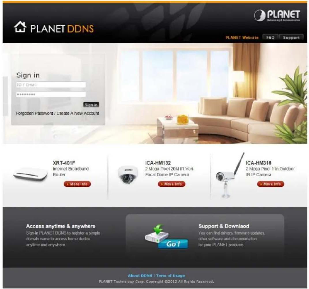

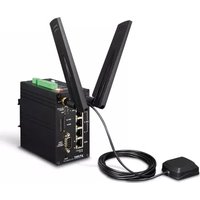
- USER'S MANUAL
- INDUSTRIAL 5G NR COMPACT CELLULAR WIRELESS GATEWAY
- COPYRIGHT
- DISCLAIMER
- FCC RADIATION EXPOSURE STATEMENT
- FCC CAUTION
- CE COMPLIANCE STATEMENT
- SAFETY
- WEEE
- TRADEMARKS
- REVISION
- TABLE OF CONTENTS
- CHAPTER 1. PRODUCT INTRODUCTION......6
- CHAPTER 2. HARDWARE INTRODUCTION ......15
- CHAPTER 3. PREPARATION ....19
- CHAPTER 4. WEB-BASED MANAGEMENT....27
- 4.5 WIRELESS 47
- CHAPTER 1. PRODUCT INTRODUCTION
- 1.1 PACKAGE CONTENTS
- 1.2 OVERVIEW
- POWERFUL 5G NR AND WI-FI 5 INDUSTRIAL NETWORK SOLUTION
- AUTOMATIC FAILOVER BETWEEN 5G NR AND GIGABIT WAN
- ULTRA-FAST SPEED 4G/5G NETWORK
- DUAL SIM DESIGN
- IDEAL HIGH-AVAILABILITY VPN SECURITY CELLULAR GATEWAY SOLUTION FOR INDUSTRIAL ENVIRONMENT
- WIRELESS 11AC BRINGS EXCELLENT DATA LINK SPEED
- EXCELLENT ABILITY IN THREAT DEFENSE
- CYBERSECURITY NETWORK SOLUTION TO MINIMIZE SECURITY RISKS
- 1.3 FEATURES
- KEY FEATURES
- HARDWARE
- CELLULAR INTERFACE
- RF INTERFACE CHARACTERISTICS
- IP ROUTING FEATURE
- FIREWALL SECURITY
- VPN FEATURES
- NETWORKING
- OTHERS
- 1.4 PRODUCT SPECIFICATIONS
- CHAPTER 2. HARDWARE INTRODUCTION
- 2.1 PHYSICAL DESCRIPTIONS
- 2.2 HARDWARE INSTALLATION
- 2.2.1 SIM CARD INSTALLATION
- 2.2.2 5G NR AND WI-FI ANTENNA INSTALLATION
- 2.2.3 WIRING THE POWER INPUTS
- 2.2.4 GROUNDING THE DEVICE
- CHAPTER 3. PREPARATION
- 3.1 REQUIREMENTS
- 3.2 SETTING TCP/IP ON YOUR PC
- WINDOWS 7/8
- WINDOWS 10
- 3.3 PLANET SMART DISCOVERY UTILITY
- CHAPTER 4. WEB-BASED MANAGEMENT
- 4.1 INTRODUCTION
- 4.2 LOGGING IN TO THE CELLULAR GATEWAY
- 4.3 MAIN WEB PAGE
- 4.4 SETUP
- 4.4.1 BASIC SETUP
- 4.4.1.1 WAN SETUP
- DISABLE
- STATIC IP
- AUTOMATIC CONFIGURATION – DHCP
- DHCP-4G
- PPPOE
- 3G LINK 1/3G LINK 2
- DHCP-BKUP4G
- KEEP ONLINE DETECTION
- STP
- OPTIONAL CONFIGURATION
- OPTIONAL SETTINGS
- 4.4.1.2 NETWORK SETUP
- ROUTER IP
- MULTIPLE LAN IP
- NETWORK ADDRESS SERVER SETTINGS (DHCP)
- DHCP FORWARDER
- TIME SETTINGS
- ADJUST TIME
- 4.4.2 DDNS
- 4.4.3 MAC ADDRESS CLONE
- 4.4.4 ADVANCED ROUTING
- 4.4.5 VLANS
- 4.4.6 NETWORKING
- 4.4.6.1 BRIDGING
- CREATE STEPS AS SHOWN BELOW
- 4.4.6.2 PORT SETUP
- 4.4.6.3 DHCPD
- 4.5 WIRELESS
- 4.5.1 BASIC SETTING
- WIRELESS PHYSICAL INTERFACE W10 [2.4 GHZ]
- PHYSICAL INTERFACE ATH0 - SSID [PLANET_ICG-2210W-NR_2.4G] HWADDR [A8:F7:E0:39:6B:A1]
- VIRTUAL INTERFACES
- WIRELESS PHYSICAL INTERFACE W10_5G [5 GHZ]
- PHYSICAL INTERFACE ATH1 - SSID [PLANET_ICG-2210W-NR_5G] HWADDR [A8:F7:E0:39:6B:A2]
- 4.5.2 WIRELESS SECURITY
- WIRELESS SECURITY W10
- WIRELESS SECURITY W10_5G
- WPA PERSONAL/WPA2 PERSONAL/WPA2 PERSON MIXED
- 4.6 SERVICES
- DHCP SERVER
- DNSMASQ
- SNMP
- SECURE SHELL
- SYSTEM LOG
- TELNET
- WAN TRAFFIC COUNTER
- 4.7 VPN
- 4.7.1 PPTP
- PPTP SERVER
- PPTP CLIENT
- 4.7.2 L2TP
- L2TP SERVER
- L2TP CLIENT
- 4.7.3 OPENVPN
- OPENVPN SERVER
- ADVANCED OPTIONS
- OPENVPN CLIENT
- 4.7.4 IPSEC
- DETECTION
- ADVANCED SETTINGS
- PHASE 1
- PHASE 2
- ENABLE IKEV2
- AUTHENTICATION
- 4.7.5 GRE
- 4.8 SECURITY
- 4.8.1 FIREWALL
- FIREWALL PROTECTION
- ADDITIONAL FILTERS
- PREVENT WAN REQUEST
- BLOCK WAN REQUESTS
- IMPEDE WAN DOS/BRUTEFORCE
- LOG MANAGEMENT
- LOG
- OPTIONS
- 4.9 ACCESS RESTRICTIONS
- 4.9.1 WAN ACCESS
- LIST OF CLIENTS
- 4.9.2 MAC FILTERING
- SET UP INTERNET ACCESS POLICY
- NOTE
- 4.9.3 PACKET FILTERING
- 4.10 NAT
- 4.10.1 PORT FORWARDING
- 4.10.2 PORT RANGE FORWARDING
- PORT RANGE FORWARD
- 4.10.3 DMZ
- DMZ
- 4.11 QOS SETTING
- 4.11.1 BASIC
- QOS
- MAIN WAN QOS SETTINGS
- BKUP WAN QOS SETTINGS
- HTB SETTING
- 4.11.2 CLASSIFY
- 4.12 APPLICATIONS
- 4.12.1 SERIAL APPLICATIONS
- 3.5 MM TERMINAL INTERFACE DEFINITION
- 4.13 ADMINISTRATION
- 4.13.1 MANAGEMENT
- ROUTER PASSWORD
- WEB ACCESS
- REMOTE ACCESS
- CRON
- REMOTE MANAGEMENT
- 4.13.2 KEEP ALIVE
- SCHEDULE REBOOT
- 4.13.3 COMMANDS
- COMMAND SHELL
- 4.13.4 FACTORY DEFAULTS
- RESET ROUTER SETTINGS
- 4.13.5 FIRMWARE UPGRADE
- FIRMWARE UPGRADE
- WARNING
- 4.13.6 BACKUP
- BACKUP CONFIGURATION
- BACKUP SETTINGS
- RESTORE CONFIGURATION
- RESTORE SETTINGS
- 4.14 STATUS
- 4.14.1 ROUTER
- ACTIVE IP CONNECTIONS TABLE
- 4.14.2 WAN
- DATA ADMINISTRATION
- 4.14.3 LAN
- 4.14.4 WIRELESS
- 2.4G WIRELESS NODES
- 5.8G WIRELESS NODES
- 4.14.5 BANDWIDTH
- 4.14.6 SYS INFO
- APPENDIX A: DDNS APPLICATION
- CONFIGURING PLANET DDNS STEPS
Brand : Planet
Model : ICG-2210W-NR
Category : Network router