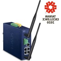
IVR-300W - Network router Planet - Free user manual and instructions
Find the device manual for free IVR-300W Planet in PDF.


| Product Type | Industrial VPN Security Gateway with Wi-Fi 6 |
| Model | IVR-300W |
| Ports | 4 x 10/100/1000T RJ45 LAN, 1 x 10/100/1000T RJ45 WAN/LAN |
| Wireless Standard | IEEE 802.11a/b/g/n/ac/ax (Wi-Fi 6) |
| Wireless Speed | Up to 600 Mbps (2.4 GHz) + 1200 Mbps (5 GHz) |
| Antenna | 2 external dual-band RP-SMA antennas (5 dBi) |
| USB Port | 1 x USB 3.0 for configuration backup and firmware upgrade |
| Serial Interface | 1 x 3-pin terminal block for RS-485 |
| Digital I/O | 2 Digital Inputs, 2 Digital Outputs |
| Power Input | Dual redundant DC 9-54V, terminal block |
| Power Consumption | Max 15.6W |
| Dimensions (W x D x H) | 50 x 135 x 135 mm |
| Weight | 773 g |
| Enclosure | IP30 metal case |
| Operating Temperature | -40°C to 75°C |
| Storage Temperature | -40°C to 85°C |
| Mounting | DIN-rail, wall mount, side wall mount |
| VPN Features | IPSec, GRE, PPTP, L2TP, SSL (OpenVPN), up to 60 tunnels |
| Firewall | SPI, DoS/DDoS protection, content filtering, MAC/IP filtering |
| Routing Protocols | Static, RIP, OSPF |
| Management | Web GUI, SNMP v1/v2c/v3, PLANET Smart Discovery, CloudViewer |
| Maintenance and Cleaning | Disconnect power before cleaning; wipe with dry cloth; keep ventilation clear; no internal user-serviceable parts |
| Safety Precautions | Use only supplied power; avoid moisture and extreme temperatures; follow installation guide for wiring |
| Spare Parts and Repairability | Antennas are replaceable (RP-SMA); power supply is external; no other user-replaceable parts; contact dealer for service |
| General Information | Compliant with CE, FCC; supports IPv4/IPv6; includes captive portal and RADIUS server |
Frequently Asked Questions - IVR-300W Planet
User questions about IVR-300W Planet
0 question about this device. Answer the ones you know or ask your own.
Ask a new question about this device
Download the instructions for your Network router in PDF format for free! Find your manual IVR-300W - Planet and take your electronic device back in hand. On this page are published all the documents necessary for the use of your device. IVR-300W by Planet.
USER MANUAL IVR-300W Planet
natural_image
Four blue network switch units with green connectors and a black cable, no visible text or symbols on the devices themselves.User's Manual
Industrial 5-Port 10/100/1000T VPN Security Gateway
IVR-100 & IVR-300 Series
natural_image
Man in white shirt and tie using laptop in server rack (no visible text or symbols)Copyright
Copyright (C) 2023 PLANET Technology Corp. All rights reserved.
The products and programs described in this User's Manual are licensed products of PLANET Technology, This User's Manual contains proprietary information protected by copyright, and this User's Manual and all accompanying hardware, software, and documentation are copyrighted.
No part of this User's Manual may be copied, photocopied, reproduced, translated, or reduced to any electronic medium or machine-readable form by any means, electronic or mechanical including photocopying, recording, or information storage and retrieval systems, for any purpose other than the purchaser's personal use, and without the prior express written permission of PLANET Technology.
Disclaimer
PLANET Technology does not warrant that the hardware will work properly in all environments and applications, and makes no warranty and representation, either implied or expressed, with respect to the quality, performance, merchantability, or fitness for a particular purpose.
PLANET has made every effort to ensure that this User's Manual is accurate; PLANET disclaims liability for any inaccuracies or omissions that may have occurred. Information in this User's Manual is subject to change without notice and does not represent a commitment on the part of PLANET. PLANET assumes no responsibility for any inaccuracies that may be contained in this User's Manual. PLANET makes no commitment to update or keep current the information in this User's Manual, and reserves the right to make improvements and/or changes to this User's Manual at any time without notice.
If you find information in this manual that is incorrect, misleading, or incomplete, we would appreciate your comments and suggestions.
FCC Compliance Statement
This Equipment has been tested and found to comply with the limits for a Class A digital device, pursuant to Part 15 of the FCC rules. These limits are designed to provide reasonable protection against harmful interference in a residential installation. This equipment can radiate radio frequency energy and, if not installed and used in accordance with the instructions, may cause harmful interference to radio communications.
However, there is no guarantee that interference will not occur in a particular installation. If this equipment does cause harmful interference to radio or television reception, which can be determined by turning the equipment off and on, the user is encouraged to try to correct the interference by one or more of the following measures:
- Reorient or relocate the receiving antenna.
- Increase the separation between the equipment and receiver.
- Connect the equipment into an outlet on a circuit different from that to which the receiver is connected.
Consult the dealer or an experienced radio/TV technician for help.
CE mark Warning

The is a class A device, In a domestic environment, this product may cause radio interference, in which case the user may be required to take adequate measures.
Safety
This equipment is designed with the utmost care for the safety of those who install and use it. However, special attention must be paid to the dangers of electric shock and static electricity when working with electrical equipment. All guidelines of this and of the computer manufacture must therefore be allowed at all times to ensure the safe use of the equipment.
WEEE

To avoid the potential effects on the environment and human health as a result of the presence of hazardous substances in electrical and electronic equipment, end users of electrical and electronic equipment should understand the meaning of the crossed-out wheeled bin symbol. Do not dispose
of WEEE as unsorted municipal waste and have to collect such WEEE separately.
Trademarks
The PLANET logo is a trademark of PLANET Technology. This documentation may refer to numerous hardware and software products by their trade names. In most, if not all cases, these designations are claimed as trademarks or registered trademarks by their respective companies.
Revision
User's Manual of PLANET Industrial 5-Port 10/100/1000T VPN Security Gateway
Model: IVR-100, IVR-300, IVR-300W, IVR-300FP
Rev.: 1.2 (June, 2023)
Part No. EM-IVR-100_IVR-300 Series_v1.2
Table of Contents
Chapter 1. Product Introduction....7
1.1 Package Contents....7
1.2 Overview 8
1.3 Features 15
1.4 Product Specifications....18
Chapter 2. Hardware Introduction....23
2.1 Physical Descriptions 23
2.1.1 Front View....23
2.1.2 Top View....27
2.1.3 Wiring the Power Inputs....28
2.1.4 Wiring the Fault Alarm Contact 29
2.1.5 Dimensions 30
2.2 Hardware Installation 34
2.2.1 DIN-rail Mounting 34
2.2.2 Wall Mount Plate Mounting 36
2.2.3 Side Wall Mount Plate Mounting....37
2.2.4 Wi-Fi Antenna Installation 38
Chapter 3. Preparation ....39
3.1 Requirements 39
3.2 Setting TCP/IP on your PC....39
3.2.1 Windows 7/8 39
3.2.2 Windows 10 43
3.3 Planet Smart Discovery Utility....46
Chapter 4. Web-based Management....48
4.1 Introduction....48
4.2 Logging in to the VPN Gateway 48
4.3 Main Web Page....51
4.4 System 53
4.4.1 Wizard 55
4.4.2 Dashboard 62
4.4.3 Status....65
4.4.4 System Service 66
4.4.5 Statistics....67
4.4.6 Connection Status....67
4.4.7 SFP Module Information 68
4.4.8 High Availability....69
4.4.9 RADIUS....70
4.4.10 Captive Portal 72
4.4.11 SNMP 73
4.4.12 NMS 74
4.4.13 Fault Alarm 76
4.4.14 Digital Input / Output 77
4.4.15 Modbus 79
4.4.16 Remote Syslog....80
4.5 Network 81
4.5.1 Priority 82
4.5.2 WAN....83
4.5.3 WAN Advanced 85
4.5.4 LAN 86
4.5.5 Multi-Subnet....86
4.5.6 VLAN 87
4.5.7 UPnP 87
4.5.8 Routing....88
4.5.9 RIP 90
4.5.10 OSPF 90
4.5.11 IGMP 90
4.5.12 IPv6....91
4.5.13 DHCP 92
4.5.14 DDNS....93
4.5.15 MAC Address Clone....95
4.6 Security 96
4.6.1 Firewall....97
4.6.2 MAC Filtering 99
4.6.3 IP Filtering....100
4.6.4 Web Filtering....101
4.6.5 Port Forwarding 102
4.6.6 QoS....103
4.6.7 DMZ 104
4.7 VPN 105
4.7.1 IPSec....107
4.7.2 IPsec Remote Server....110
4.7.3 GRE 110
4.7.4 PPTP 112
4.7.5 L2TP....113
4.7.6 SSL VPN 115
4.7.7 Certificates 116
4.7.8 VPN Connection 116
4.7.9 SD WAN....116
4.8 AP Control 117
4.8.1 Preference 119
4.8.2 AP Search....119
4.8.3 AP Management 120
4.8.4 AP Group Management 121
4.8.5 SSID Profile 122
4.8.6 Radio 2.4GHz Profile 124
4.8.7 Radio 5GHz Profile....125
4.8.8 Statistics AP Status....126
4.8.9 Map It 126
4.8.10 Upload Map....127
4.9 Wireless....128
4.9.1 2.4GHz WiFi....129
4.9.2 5GHz WiFi....130
4.9.3 MAC ACL 131
4.9.4 Wi-Fi Advanced....132
4.9.5 Wi-Fi Statistics 133
4.9.6 Connection Status....133
4.10 Power over Ethernet 134
4.10.1 PoE Configuration....134
4.10.2 PoE Status....136
4.10.3 PoE Schedule 136
4.10.4 PD Alive Check 138
4.11 Maintenance....139
4.11.1 Administrator....140
4.11.2 Date and Time....141
4.11.3 Saving/Restoring Configuration 142
4.11.4 Firmware Upgrade 143
4.11.5 Reboot / Reset 144
4.11.6 Auto Reboot....144
4.11.7 Diagnostics 145
Appendix A: DDNS Application 146
Chapter 1. Product Introduction
Thank you for purchasing PLANET Industrial Security Gateway, IVR-100 and IVR-300 series. The descriptions of these models are as follows
| IVR-100 | Industrial 5-Port 10/100/1000T VPN Security Gateway |
| IVR-300 | Industrial 5-Port 10/100/1000T VPN Security Gateway with Redundant Power |
| IVR-300W | Industrial 5-Port 10/100/1000T + 802.11ax Wi-Fi VPN Security Gateway |
| IVR-300FP | Industrial 4-Port 10/100/1000T 802.3at PoE + 1-Port 10/100/1000T + 1-Port 1000XSFP VPN Security Gateway |
"VPN Gateway" mentioned in the manual refers to the above models.
1.1 Package Contents
The package should contain the following:
| Item\Model | IVR-100 | IVR-300 | IVR-300W | IVR-300FP |
| VPN Gateway | x 1 | x 1 | x 1 | x 1 |
| Quick Installation Guide | x 1 | x 1 | x 1 | x 1 |
| Wall-mount Kit | x 1 | x 1 | x 1 | x 1 |
| RJ45 Dust Cap | x 5 | x 5 | x 5 | x 5 |
| SFP Dust Cap | x 1 | |||
| CloudViewer QIG | x 1 | x 1 | x 1 | x 1 |
| RS485 3-pin Terminal Block | - | x 1 | x 1 | x 1 |
| Dual band Wi-Fi Antenna | - | - | x 2 | - |
| Antenna Dust Cap | - | - | x 2 | - |

Note
If any of the above items are missing, please contact your dealer immediately.
1.2 Overview
Powerful Industrial VPN Security Solution
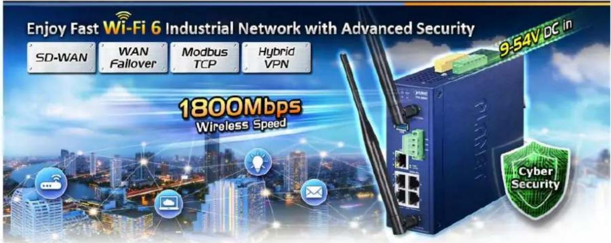
PLANET has launched the IVR-100 and IVR-300 Series Security Gateway for demanding applications. It features five Ethernet ports (4 LANs and 1 WAN), IEEE 11ax Wi-Fi capability (for IVR-300W), one Fiber port (for IVR-300FP), RS485 serial port (for IVR-300 series), and DI and DO interfaces. Incorporating SD-WAN function, it can greatly increase WAN optimization for multiple WAN links to be managed.
Furthermore, its Dual-WAN Failover and Outbound Load Balance features can improve the network efficiency while the web-based interface provides friendly and user experience.
It's ideal for the harsh environment as it can operate stably at temperatures from -40 to 75 degrees C. Its compact IP30 metal case allows either DIN-rail or wall mounting for efficient use of cabinet space.

Flexible WAN interface Enables Extension of Network Deployment (For IVR-300FP)
The IVR-300FP provides both copper and fiber connectors for WAN interface. With one SFP slot, it supports fiber extension for FTTX application. It allows the administrator to flexibly choose the suitable SFP transceiver according to the transmission distance required to extend the network efficiently. The distance can be extended from 550 meters to 2 kilometers (multi-mode fiber) and 10/20/30/40/50/60/70/120 kilometers (single-mode fiber or WDM fiber). They are well suited for applications to uplink to backbone switch and monitoring center in long distance.
Intelligent SFP Diagnosis Mechanism (For IVR-300FP)
The IVR-300FP supports SFP-DDM (digital diagnostic monitor) function that greatly helps network administrator to easily monitor real-time parameters of the SFP, such as optical output power, optical input power, temperature, laser bias current, and transceiver supply voltage.

flowchart
graph TD
    A["SFP DDM (Digital Diagnostic Monitor)"] --> B["Voltage"]
    A --> C["Ammeter"]
    A --> D["Temperature"]
    A --> E["Power Transceiver"]
    A --> F["Power Receiver"]
Built-in Unique PoE Functions for Powered Devices Management (For IVR-300FP)
The IVR-300FP is capable of having a maximum of up to 120 watts of power output and can deliver up to 36W for each port. It also features the following special PoE management functions.
PoE Usage Monitoring (For IVR-300FP)
With PoE usage monitoring, it can show the PoE loading of each port, total PoE power usage and system status, such as overload, low voltage, over voltage and high temperature. User can obtain detailed information about the real-time PoE working condition of the IVR-300FP directly.
PoE Schedule (For IVR-300FP)
Under the trend of energy saving worldwide and contributing to environmental protection, the IVR-300FP can effectively control the power supply besides its capability of giving high watts power. The "PoE schedule" function helps you to enable or disable PoE power feeding for each PoE port during specified time intervals and it is a powerful function to help SMBs or enterprises save power and budget. It also increases security by powering off PDs that should not be in use during non-business hours.

line
PoE Schedule | Time Period | Total Consumption (Watts/hr) | | :--- | :--- | | 08:00~17:00 | 36 | | 17:00~08:00 | 24 |Scheduled Power Recycling (For IVR-300FP)
The IVR-300FP allows each of the connected PoE IP cameras or PoE wireless access points to reboot at a specific time each week. Therefore, it will reduce the chance of IP camera or AP crash resulting from buffer overflow.

flowchart
graph TD
    A["IP Camera"] --> B["AP Router"]
    A --> C["IP Phone"]
    A --> D["Door Phone"]
    A --> E["PoE lighting"]
    B --> F["Automatic Reboot"]
    C --> F
    D --> F
    E --> F
PD Alive Check (For IVR-300FP)
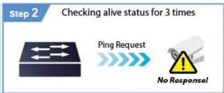
The IVR-300FP can be configured to monitor connected PD status in real time via ping action. Once the PD stops working and responding, the IVR-300FP will resume the PoE port power and bring the PD back to work. It will greatly enhance the network reliability through the PoE port resetting the PD's power source and reducing administrator management burden.
PD Alive Check

flowchart
graph LR
    A["Step 1"] --> B["Ping Request"]
    B --> C["Ping Echo"]

flowchart
graph LR
    A["Alarm Notification"] --> B["ON"]
    A --> C["OFF"]
    B --> D["Stop"]
    C --> E["Stop"]

Wireless 11ax Brings Excellent Data Link Speed (For IVR-300W)
The IVR-300W is designed with high power amplifier and 2 highly-sensitive antennas which provide stronger signal and excellent coverage even in the wide-ranging or bad environment. With adjustable transmit power option, the administrator can flexibly reduce or increase the output power for various environments, thus reducing interference to achieve maximum performance. Equipped with the next-generation Wi-Fi 6 (802.11ax) wireless network standard, the total bandwidth reaches 1800Mbps, and the 2-stream transmission technology improves the transmission efficiency of multiple devices, making AR/VR/IoT applications smoother. The IEEE 802.11ax also optimizes MU-MIMO (Multi-User MIMO) mechanism to serve multiple devices simultaneously.
Ideal VPN Security Gateway Solution for Factories and Transportations
The IVR-100 and IVR-300 Series provides complete data security and privacy for accessing and exchanging the most sensitive data, built-in IPSec VPN function with DES/3DES/AES encryption and MD5/SHA-1/SHA-256/SHA-384/SHA-512 authentication, and GRE, SSL, PPTP and L2TP server mechanism. The full VPN capability in the IVR-100 and IVR-300 Series makes the connection secure, more flexible, and more capable.

flowchart
graph LR
    A["Industrial VPN Security Gateway"] --> B["Content Filtering"]
    B --> C["VPN Tunnel"]
    C --> D["Failure Switch"]
    D --> E["Network"]
    style A fill:#f9f,stroke:#333
    style B fill:#bbf,stroke:#333
    style C fill:#dfd,stroke:#333
    style D fill:#fff,stroke:#333
    style E fill:#dfd,stroke:#333
Centralized Remote Control of Managed APs
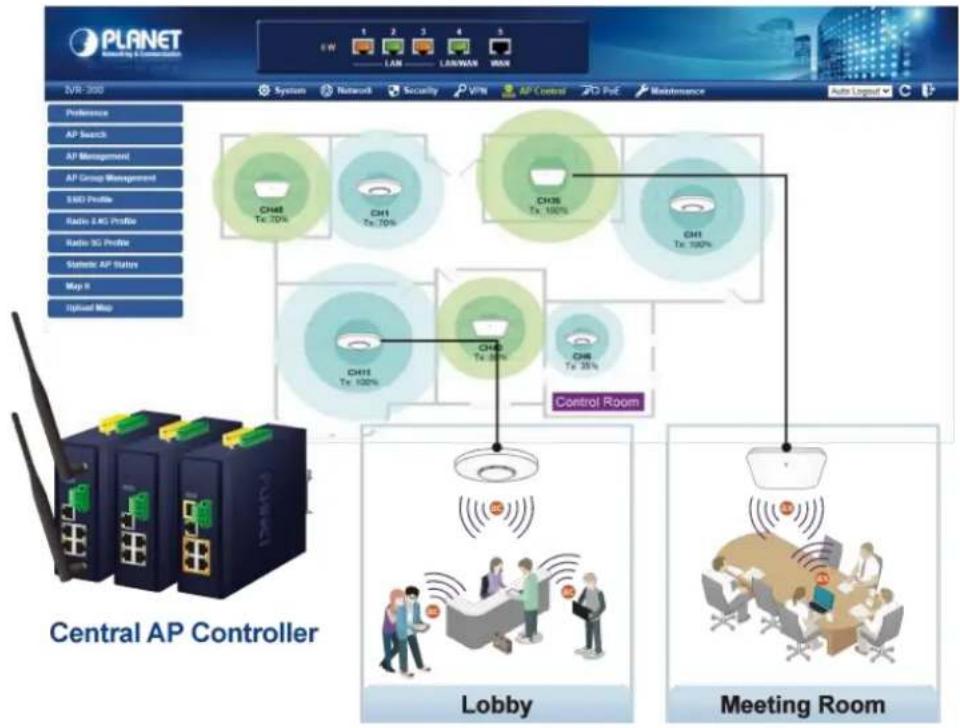
The IVR-100 and IVR-300 Series provides centralized management of PLANET Smart AP series via a user-friendly Web GUI. It's easy to configure AP for the wireless SSID, radio band and security settings. With a four-step configuration process, wireless profiles for different purposes can be simultaneously delivered to multiple APs or AP groups to minimize deployment time, effort and cost.
flowchart
graph TD
    A["Central AP Controller"] --> B["Lobby"]
    A --> C["Meeting Room"]
    B --> D["CH48 Tx: 70%"]
    B --> E["CH1 Tx: 70%"]
    B --> F["CH36 Tx: 100%"]
    B --> G["CH12 Tx: 100%"]
    C --> H["CH48 Tx: 35%"]
    C --> I["CH6 Tx: 35%"]
    D --> J["Control Room"]
    E --> J
    F --> J
    G --> J
    H --> J
    I --> J
For example, to configure multiple smart APs of the same model, the IVR-100 and IVR-300 Series allows clustering them to a managed group for unified management. According to requirements, wireless APs can be flexibly expanded or removed from a wireless AP group at any time. The AP cluster benefits bulk provision and bulk firmware upgrade through single entry point instead of having to configure settings in each of them separately.
Simplified Cluster Management with 4 Steps

flowchart
graph LR
    A["Search"] --> B["Add Profile"]
    B --> C["Batch Provisioning"]
    C --> D["Map It"]
Wi-Fi Deployments and Authentication with Simplified Management (for IVR-300 Series)
The IVR-300 Series also provides a built-in AP Controller, Captive Portal, RADIUS and a DHCP server to facilitate small and medium businesses to deploy secure employee and guest access services without any additional server. The IVR-300 Series can offer a secure Wi-Fi network with easy installation for your business.

flowchart
graph TD
    A["Captive Portal"] --> B["Free Wi-fi"]
    B --> C["Name"]
    B --> D["E-mail"]
    B --> E["OK"]
    C --> F["WWW"]
    D --> F
    E --> F
Excellent Ability in Threat Defense
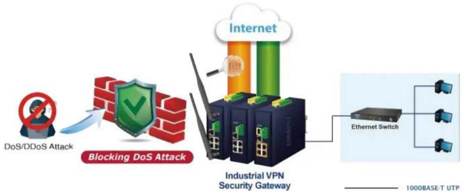
The IVR-100 and IVR-300 Series has built-in SPI (stateful packet inspection) firewall and DoS/DDoS attack mitigation functions to provide high efficiency and extensive protection for your network. Thus, virtual server and DMZ functions can let you set up servers in the Intranet and still provide services to the Internet users.
flowchart
graph LR
    A["DoS/DDoS Attack"] --> B["Blocking DoS Attack"]
    B --> C["Industrial VPN Security Gateway"]
    C --> D["Ethernet Switch"]
    D --> E["1000BASE-T UTP"]
    style A fill:#f9f,stroke:#333
    style B fill:#ccf,stroke:#333
    style C fill:#cfc,stroke:#333
    style D fill:#fcc,stroke:#333
    style E fill:#cff,stroke:#333
Cybersecurity Network Solution to Minimize Security Risks
The cybersecurity feature included to protect the switch management in a mission-critical network virtually needs no effort and cost to install. For efficient management, the IVR-100 and IVR-300 Series are equipped with HTTPS web and SNMP management interfaces. With the built-in web-based management interface, the IVR-100 and IVR-300 Series offers an easy-to-use, platform independent management and configuration facility. IVR-100 and IVR-300 Series supports SNMP and it can be managed via any management software based on the standard SNMP protocol.
Maximizing Work Efficiency with PLANET SD-WAN Gateway
PLANET IVR-100 and IVR-300 Series incorporated in SD-WAN (software-defined wide area network) function can greatly increase WAN optimization for multiple WAN links to be managed. With SD-WAN, users can connect any application across all available network connections at every site. It improves application performance and provides a high-quality user experience for increasing business productivity and reducing IT costs.
Cost-effective Solution for RS-485 to Ethernet Application (for IVR-300 Series.)
The IVR-100 and IVR-300 Series provides a feature that can convert the Serial RS-485 communication to IP networking. Ethernet signal allows two types of segments to connect easily, efficiently and inexpensively. The solution helps users and SIs save expenses as there is no need to replace the existing serial equipment and software system.

flowchart
graph LR
    A["Workstation"] -->|TCP/IP Protocol| B["IVR-300 Series"]
    B -->|Serial bus RS485| C["Serial Devices"]
Convenient and Reliable Redundant Power System
To facilitate transportation and industrial-level applications, the IVR-100 and IVR-300 Series provides an integrated power solution with a wide range of voltages (9\~54V DC) for worldwide operability, and the IVR-300FP provides an integrated power solution with 48\~54V DC voltages. It also provides dual-redundant, reversible polarity DC power supply inputs for high availability applications.
Ideal VPN Security Gateway
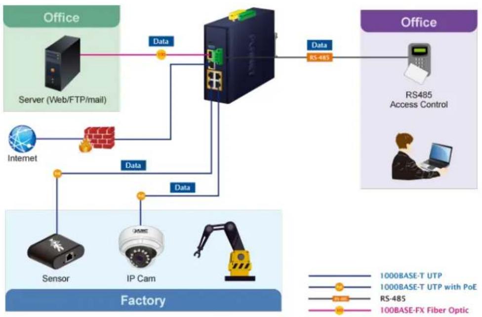
PLANET IVR-100 and IVR-300 Series can work as a VPN security gateway in an industrial application for a company that has a factory and many different divisions. With IPSec/GRE/PPTP/L2TP/SSL VPN solutions, the IVR-100 and IVR-300 Series installed at the headquarters provides branches, vendors, and mobile workers with secure data communication no matter how long the distance would be.
The IVR-100 and IVR-300 Series connects dual WANs with up to two different ISPs. It creates a stable and qualified VPN connection for many important applications such as VoIP, video conferencing and data transmission.
flowchart
graph TD
    subgraph Office
        A["Server (Web/FTP/mail)"] -->|Data| B["Network Unit"]
        C["Internet"] -->|Data| B
        D["Sensor"] -->|Data| B
        E["IP Cam"] -->|Data| B
        F["Robot Arm"] -->|Data| B
    end

    subgraph Factory
        G["100BASE-T UTP"] --> H["RS-485 Access Control"]
        I["100BASE-T UTP with PoE"] --> H
        J["RS-485"] --> H
        K["100BASE-FX Fiber Optic"] --> H
    end

    B --> L["Data"]
    style B fill:#f9f9f9,stroke:#333
    style H fill:#e6f7ff,stroke:#333
    style I fill:#e6f7ff,stroke:#333
    style J fill:#e6f7ff,stroke:#333
    style K fill:#e6f7ff,stroke:#333
1.3 Features
Hardware
■ 4 x 10/100/1000BASE-T RJ45 LAN ports (for IVR-100 and IVR-300/IVR-300W)
■ 4 x 10/100/1000BASE-T RJ45 LAN ports with 4-port IEEE 802.3at PoE+ injector function (for IVR-300FR)
■ 1 1000BASE-X SFP slot for WAN/LAN interface(for IVR-300FR)
■ 1 10/100/1000BASE-T RJ45 WAN/LAN port
■ Dual-WAN failover and Dual-WAN load balancing
■ 1 USB 3.0 port for system configuration backup and firmware upgrade
■ 1 reset button
■ 1 3-pin terminal block (RS485) (for IVR-300 Series)
■ 2 x DIDO (for IVR-300 Series)
Power over Ethernet (for IVR-300FP)
■ Complies with IEEE 802.3at Power over Ethernet Plus, end-span PSE
■ Backward compatible with IEEE 802.3af Power over Ethernet
■ Up to 4 ports of IEEE 802.3af / 802.3at devices powered
■ Supports PoE power up to 36 watts for each PoE port
■ Auto detects powered device (PD)
■ Circuit protection prevents power interference between ports
■ PoE management
■ Total PoE power budget control
◆ Per port PoE function enable/disable
◆ PoE port power feeding priority
◆ Per PoE port power limitation
◆ PD classification detection
◆ PD alive check
RF Interface Characteristics (for IVR-300W)
■ Features 2.4GHz (802.11b/g/n/ax) and 5GHz (802.11a/n/ac/ax) dual band for carrying high load traffic
■ 2T2R MIMO technology for enhanced throughput and coverage
■ Provides multiple adjustable transmit power control
■ High speed up to 1.8Gbps (600Mbps for 2.4GHz or 1200Mbps for 5GHz) wireless data rate
Industrial Case and Installation
■ IP30 metal case
■ Solid DIN-rail, wall-mount or side wall-mount design
■ Supports 6KV DC Ethernet ESD protection
■ Fault alarm for power input failure
■ DC redundant power with reverse polarity protection
■ -40 to 75 degrees C operating temperature
IP Routing Feature
■ Static Route
■ Dynamic Route (RIPv1/v2)
Firewall Security
■ Cybersecurity
■ Stateful Packet Inspection (SPI) firewall
■ Blocks DoS/DDoS attack
■ Content filtering
■ MAC/IP filtering
■ Blocks SYN/ICMP flooding
■ NAT ALGs (Application Layer Gateway)
VPN Features
■ IPSec/Remote Server (Net-to-Net, Host-to-Net), GRE, PPTP Server, L2TP Server, SSL Server/Client (Open VPN)
■ Max. Connection Tunnel Entries: 60 VPN tunnels,
■ Encryption methods: DES, 3DES, AES, AES-128/192/256
■ Authentication methods: MD5, SHA-1, SHA-256, SHA-384, SHA-512
Networking
■ Outbound load balancing for Ethernet WANs
■ Auto-failover between Ethernet network WANs
■ High Availability
■ Captive Portal
■ RADIUS Server
■ Static IP/PPPoE/DHCP client for WAN
■ DHCP server/NTP client for LAN
■ Protocols: TCP/IP, UDP, ARP, IPv4, IPv6
■ Port forwarding, QoS, DMZ, IGMP, UPnP, SNMPv1,v2c, v3
■ MAC address clone
■ DDNS: PLANET DDNS, Easy DDNS, DynDNS and No-IP
Others
■ Setup wizard
■ Dashboard for real-time system overview
■ Support for HTTP or HTTPS
■ Auto reboot
■ PLANET NMS System and Smart Discovery Utility for deployment management
■ PLANET CloudViewer app for real-time monitoring
■ Configuration backup and restoration via remote/USB port
■ Firmware upgrade via remote/USB port
1.4 Product Specifications
| Product | IVR-100 | IVR-300 | IVR-300W | IVR-300FP | |
| Hardware Specifications | |||||
| Copper Ports | 5 10/100/1000BASE-T RJ45 Ethernet ports including3 LAN ports (Ports 1 to 3)1 LAN/WAN port (Port 4)1 WAN port (Port 5) | ||||
| Fiber Port | - | - | - | 1 1000BASE-XSFP slot including1 WAN/LAN port(Port 6) | |
| USB Port | 1 USB 3.0 port | ||||
| Wireless Connector | - | - | Two RP-SMA female connectors | ||
| Wireless Antenna | - | - | Two 5 dBi external antennas | ||
| Serial Interface | - | 1 x 3-pin terminal block for RS485 | |||
| DI Interfaces | - | 2 Digital Input (DI):Level 0: -24V~2.1V (±0.1V)Level 1: 2.1V~24V (±0.1V)Input Load to 24V DC, 10mA max. | |||
| DO Interfaces | - | 2 Digital Output (DO):Open collector to 24V DC, 100mA max. | |||
| Connector | Removable 6-pin terminal block for power inputPin 1/2 for Power 1, Pin 3/4 for fault alarm, Pin 5/6 for Power 2 | ||||
| Reset Button | < 5 sec: System reboot>5 sec: Factory default | ||||
| Enclosure | IP30 metal case | ||||
| Installation | DIN rail, desktop, wall-mounting | ||||
| Dimensions (W x Dx H) | 50 x 87.5 x 135 mm | 50 x 135 x 135 mm | |||
| Weight | 530g | 712g | 773g | 765g | |
| Power Requirements -DC | 9~54V DC, 1.0A | 9~54V DC, 1.8A | 9~54V DC, 1.8A | 48~54V DC, 3A | |
| Power Consumption | No Loading | Max. 3.8 watts/12.97 BTU | Max. 3.7 watts/12.61 BTU | Max. 3.8 watts/12.95 BTU | Max. 7.56 watts/25.8 BTU |
| Full Loading | Max. 9 watts/30.71 BTU | Max. 8.7 watts/29.66 BTU | Max.15.6 watts/53.19 BTU | Max. 127 watts/433.34 BTU | |
| LED Indicators | System:P1 (Green)P2 (Green)Fault (Red)Per 10/100/1000RJ45 Ports (Ports1-4 and WAN Port):1000 LNK/ACT(Green)10/100 LNK/ACT(Amber) | System:P1 (Green)P2 (Green)Alarm (Red)I/O (Red)Per 10/100/1000RJ45 Ports (Ports1-4 and WAN Port):1000 LNK/ACT(Green)10/100 LNK/ACT(Amber) | System:P1 (Green)P2 (Green)Alarm (Red)I/O (Red)Per 10/100/1000RJ45 Ports (Ports1-4and WAN Port):1000 LNK/ACT(Green)10/100 LNK/ACT(Amber)Wi-Fi:2.4G (Green)5G (Green) | System:P1 (Green)P2 (Green)Alarm (Red)I/O (Red)Per 10/100/1000RJ45 Ports (Ports1-4):LNK/ACT (Green)PoE-in-Use (Amber)Per 10/100/1000RJ45 Ports (Ports5):LNK/ACT (Green)1000 LNK (Amber)Per 1000BASE-XSFP Interfaces(Port 6):LNK/ACT (Green) | |
| Security Service | ||
| Firewall Security | CybersecurityStateful Packet Inspection (SPI)Blocks DoS/DDoS attack | |
| ALG (Application Layer Gateway) | SIP, RTSP, FTP, H.323, TFTP | |
| NAT | Port forwardingDMZ HostUPnP | |
| Content Filtering | MAC filteringIP filteringWeb filtering | |
| Bandwidth Management | Outbound load balancingFailover for dual-WANQoS (Quality of Service) | |
| Firewall Security | CybersecurityStateful Packet Inspection (SPI)Blocks DoS/DDoS attack | |
| Operation Mode | Routing mode | |
| Routing Protocol | Static Route, Dynamic Route (RIP), OSPF | |
| VLAN | 802.1q Tag-based, Port-based, Multi-VLAN | |
| Multicast | IGMP Proxy | |
| NAT Throughput | Max. 900Mbps | |
| Outbound Load Balancing | Supported algorithms: Weight | |
| Protocol | IPv4, IPv6, TCP/IP, UDP, ARP, HTTP, HTTPS, NTP, DNS, PLANET DDNS, PLANET Easy DDNS, DHCP, PPPoE, SNMPv1/v2c/v3 | |
| Key Features | HA (High Availability) Captive Portal RADIUS Server/Client AP Control | |
| VPN | ||
| VPN | IPSec/Remote Server (Net-to-Net, Host-to-Net) GRE PPTP Server L2TP Server SSL Server/Client (Open VPN) | |
| VPN Tunnels | Max. 60 | Max. 60 |
| VPN Throughput | Max. 60Mbps | Max. 108Mbps |
| Encryption Methods | DES, 3DES, AES or AES-128/192/256 encrypting | |
| Authentication Methods | MD5/SHA-1/SHA-256/SHA-384/SHA-512 authentication algorithm | |
| Management | ||
| Basic Management Interfaces | Web browser SNMP v1, v2c PLANET Smart Discovery utility and NMS controller supported | |
| Secure Management Interfaces | TLSv1.2, SNMP v3 | |
| System Log | System Event Log | |
| Others | Setup wizard Dashboard System status/service Statistics Connection status Auto reboot | |
| DiagnosticsConfiguration backup and restoration via remote/USB portFirmware upgrade via remote/USB port | ||
| Standards Conformance | ||
| Regulatory Compliance | CE, FCC | |
| Environment | ||
| Operating | Temperature: -40 ~ 75 degrees CRelative humidity: 5 ~ 90% (non-condensing) | |
| Storage | Temperature: -40 ~ 85 degrees CRelative humidity: 5 ~ 90% (non-condensing) | |
Advanced Functions
■ Power of Ethernet Specification for IVR-300FP
| Model | IVR-300FP |
| Wireless | |
| PoE Standard | IEEE 802.3af / 802.3at PoE+ PSE |
| PoE Power Supply Type | End-span |
| PoE Power Output | Per port 54V DC, 35 watts (max.) |
| Power Pin Assignment | 1/2 (+), 3/6 (-) |
| PoE Power Budget | 120 watts (max.) |
| Max. Number of Class 4 PDs | 4 |
| PoE Management | PD Alive CheckScheduled Power RecyclingPoE SchedulePoE Usage Monitoring |
■ Wireless Specification for IVR-300W
| Model | IVR-300W | |
| Wireless | ||
| Standard | IEEE 802.11a/n/ac/ax 5GHzIEEE 802.11g/b/n/ax 2.4GHz | |
| Band Mode | 2.4G & 5G concurrent mode | |
| Antenna | 5 dBi external antennas with SMA connectors for Wi-Fi | |
| Frequency Range | 2.4GHz | America FCC: 2.412~2.462GHzEurope ETSI: 2.412GHz~2.472GHz |
| 5GHz | 5.15GHz ~5.875GHz | |
| Operating Channels | 2.4GHz5GHz | America FCC: 1~11Europe ETSI: 1~13America FCC:Non-DFS: 36, 40, 44, 48, 149,153,157,161,165DFS: 52, 56, 60, 64, 100, 104, 108, 112, 116, 132, 136, 140Europe ETSI:Non-DFS: 36, 40, 44, 48DFS: 52, 56, 60, 64, 100, 104, 108, 112, 116, 120, 124, 128, 132, 136, 1405GHz channel list may vary in different countries according to their regulations. |
| Channel Width | ||
| Data Transmission Rates | Transmit: 600 Mbps* for 2.4 GHz and 1200 Mbps* for 5 GHzReceive: 600 Mbps* for 2.4 GHz and 1200 Mbps* for 5 GHz*The estimated transmission distance is based on the theory. The actual distance may vary in different environments. | |
| Transmission Power | 11b: 23dbm+/- 1.5dbm @11Mbps11g: 20dbm+/- 1.5dbm @54Mbps11g/n: 20dBm +/- 1.5dbm @MCS7, HT2017dBm@MCS7,HT4011a: 19.5dBm +/- 1.5dbm @54Mbps11a/n: 19.5dBm+/- 1.5dbm @MCS7, HT2017dBm@MCS7, HT4011ac HT20: 20+/-1.5dBm @MCS811ac HT40: 17+/-1.5dBm @MCS911ac HT80: 14.5+/-1.5dBm @MCS911ax HT20: 20+/-1.5dBm @MCS911ax HT40: 17 +/- 1.5dBm @MCS911ax HT80: 14.5 +/- 1.5dBm @MCS11 | |
| Encryption Security | WEP (64/128-bit) encryption securityWPA / WPA2 (TKIP/AES)WPA-PSK / WPA2-PSK (TKIP/AES)/ WPA3-PSK (TKIP/AES)802.1x Authenticator | |
| Wireless Advanced | Wi-Fi Multimedia (WMM)Auto channel selectionWireless output power managementMAC address filtering | |
Chapter 2. Hardware Introduction
2.1 Physical Descriptions
2.1.1 Front View
IVR-100 Front Panel

| LED | Color | Function | |
| P1 | Green | Lights to indicate DC power input 1 has power. | |
| P2 | Green | Lights to indicate DC power input 2 has power. | |
| Fault | Red | Lights to indicate the either power or port fail | |
| 1000LNK/ACT | Green | Lights | Indicates the link through that port is successfully established at 1000Mbps |
| Blinks | Indicates that the Switch is actively sending or receiving data over that port. | ||
| 100LNK/ACT | Amber | Lights | Indicates the link through that port is successfully established at 100Mbps. |
| Blinks | Indicates that the Switch is actively sending or receiving data over that port. | ||
| Ports | |||
| USB Port | USB 3.0 port for system configuration backup and restoration. | ||
| Reset Button | Power on the device and press the reset button for less than 5 seconds to reboot it or over 5 seconds to restore it to factory default settings. | ||
| Gigabit Ports 1-3 | It is a LAN port for connecting to a switch. | ||
| Gigabit Port 4 | Default is LAN port. It can be defined as LAN port or WAN port. | ||
| Gigabit Port 5 | It is a WAN port for connecting to a perimeter gateway. | ||
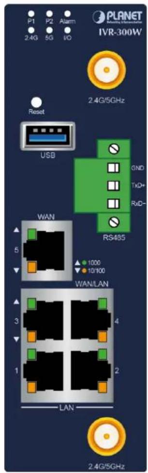
IVR-300 series Front Panel
IVR-300

IVR-300W
VR-300FP
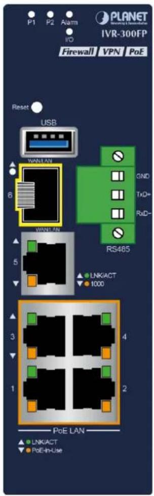
LED Definition:
- System:
| LED | Color | Function |
| P1 | Green | Lights to indicate DC power input 1 has power. |
| P2 | Green | Lights to indicate DC power input 2 has power. |
| Alarm | Red | Lights to indicate the either power or port fail |
| I/O | Red | Indicate Condition of Digital Input or Digital Output has triggered. |
| 2.4G | Green | Lights up when 2.4G Wi-Fi service is enabled (for IVR-300W) |
| 5G | Green | Lights up when 5G Wi-Fi service is enabled (for IVR-300W) |
- Interface:
300/IVR-300W
Per 10/100/1000Mbps RJ45 Port (Ports 1 to 5)
| LED | Color | Function | |
| 1000LNK/ACT | Green | Lights | Indicates the link through that port is successfully established at 1000Mbps |
| Blinks | Indicates that the Switch is actively sending or receiving data over that port. | ||
| 100LNK/ACT | Amber | Lights | Indicates the link through that port is successfully established at 100Mbps. |
| Blinks | Indicates that the Switch is actively sending or receiving data over that port. | ||
IVR-300FP
Per 10/100/1000Mbps RJ45 Port (Ports 1 to 4)
| LED | Color | Function | |
| 10/1001000LNK/ACT | Green | Lights | Indicates the link through that port is successfully established at 1000Mbps |
| Blinks | Indicates that the Switch is actively sending or receiving data over that port. | ||
| PoE-In-use | Amber | Lights | Indicates the port is providing DC in-line power. |
| Off | Indicates the connected device is not a PoE PD. | ||
10/100/1000Mbps RJ45 WAN/LAN Port (Port 5)
| LED | Color | Function | |
| 10/100/1000LNK/ACT | Green | Lights | Indicates that the port is operating at 1000Mbps, 100Mbps or 10Mbps. |
| Blinks | Indicates that the switch is actively sending or receiving data over that port. | ||
| 1000 LNK | Amber | Lights | Indicates the port is operating at 1000Mbps |
| Blinks | Indicates that the Switch is actively sending or receiving data over that | ||
1000BASE-X SFP WAN/LAN Port (Port 6)
| LED | Color | Function | |
| 1000LNK/ACT | Green | Lights | Indicates the port is operating at 1000Mbps. |
| Blinks | Indicates that the switch is actively sending or receiving data over that port. | ||
| Ports | |
| USB Port | USB 3.0 port for system configuration backup and restoration. |
| Reset Button | Power on the device and press the reset button for less than 5 seconds to reboot it or over 5 seconds to restore it to factory default settings. |
| Serial Interface | 1 x 3-pin terminal block for RS485 |
| Gigabit Ports 1-3 | It is a LAN port for connecting to a switch. |
| Gigabit Port 4 | Default is LAN port.It can be defined as LAN port or WAN port. (for IVR-300/IVR-300W) |
| Gigabit Port 5 | Default is WAN port.It is a WAN port for connecting to a perimeter gateway. (for IVR-300/IVR-300W)It can be defined as LAN port or WAN port. (for IVR-300FP) |
| SFP Port 6 | (for IVR-300FP)Default is LAN port. It can be defined as LAN port or WAN port. |
2.1.2 Top View
The upper panel of the Industrial Gateway consists of one terminal block connector within two DC power inputs.
IVR-100 Top View

IVR-300/IVR-300W Top View
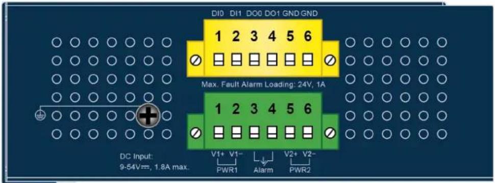
IVR-300FP Top View

2.1.3 Wiring the Power Inputs
The 6-contact terminal block connector on the top panel of Industrial Gateway is used for two DC redundant power inputs. Please follow the steps below to insert the power wire.

When performing any of the procedures like inserting the wires or tightening the wire-clamp screws, make sure the power is OFF to prevent from getting an electric shock.
- Insert positive and negative DC power wires into contacts 1 and 2 for POWER 1, or 5 and 6 for POWER 2.v


To avoid damage, please use the Industrial Gateway under its specification.
- Tighten the wire-clamp screws for preventing the wires from loosening.
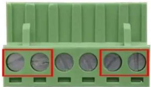
natural_image
Green electrical connector pinout with four circular holes highlighted in red (no text or symbols)1 2
3 4
5 6
Power 1
Alarm
Power 2
+ -
+ -

Note
The wire gauge for the terminal block should be in the range from 12 to 24 AWG.

PWR1 and PWR2 must provide the same DC voltage while operating with dual power input.
2.1.4 Wiring the Fault Alarm Contact
The fault alarm contacts are in the middle of the terminal block connector as the picture shows below. Inserting the wires, the Industrial Gateway will detect the fault status of the power failure and then forms an open circuit. The following illustration shows an application example for wiring the fault alarm contacts.
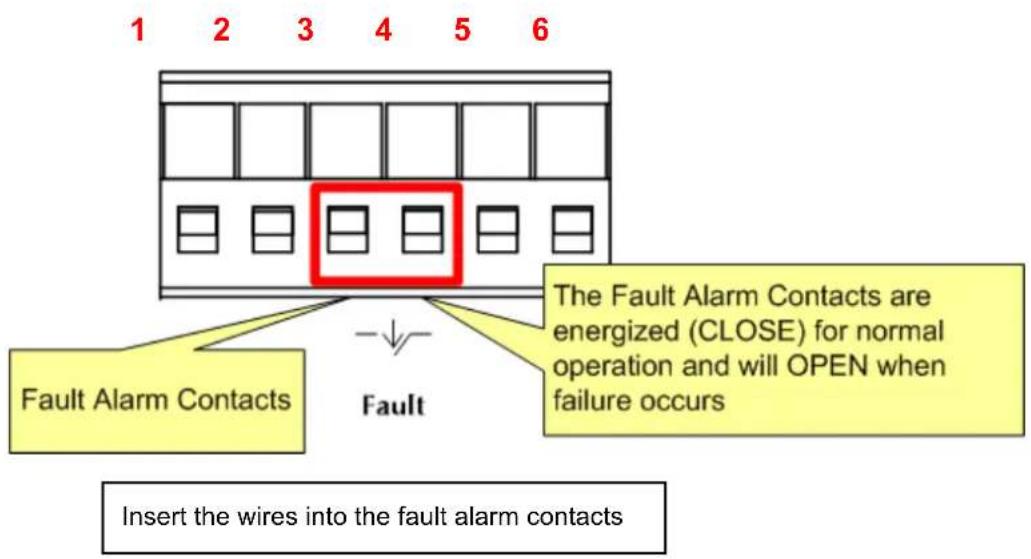

Note
- The wire gauge for the terminal block should be in the range between 12 and 24 AWG.
- Alarm relay circuit accepts up to 24V, max. 1A currents.
2.1.5 Dimensions
IVR-100 Dimensions
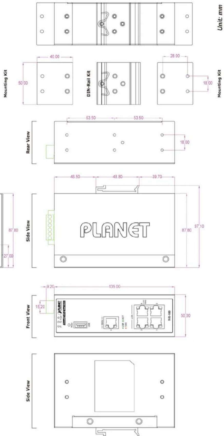

IVR-300 Dimensions
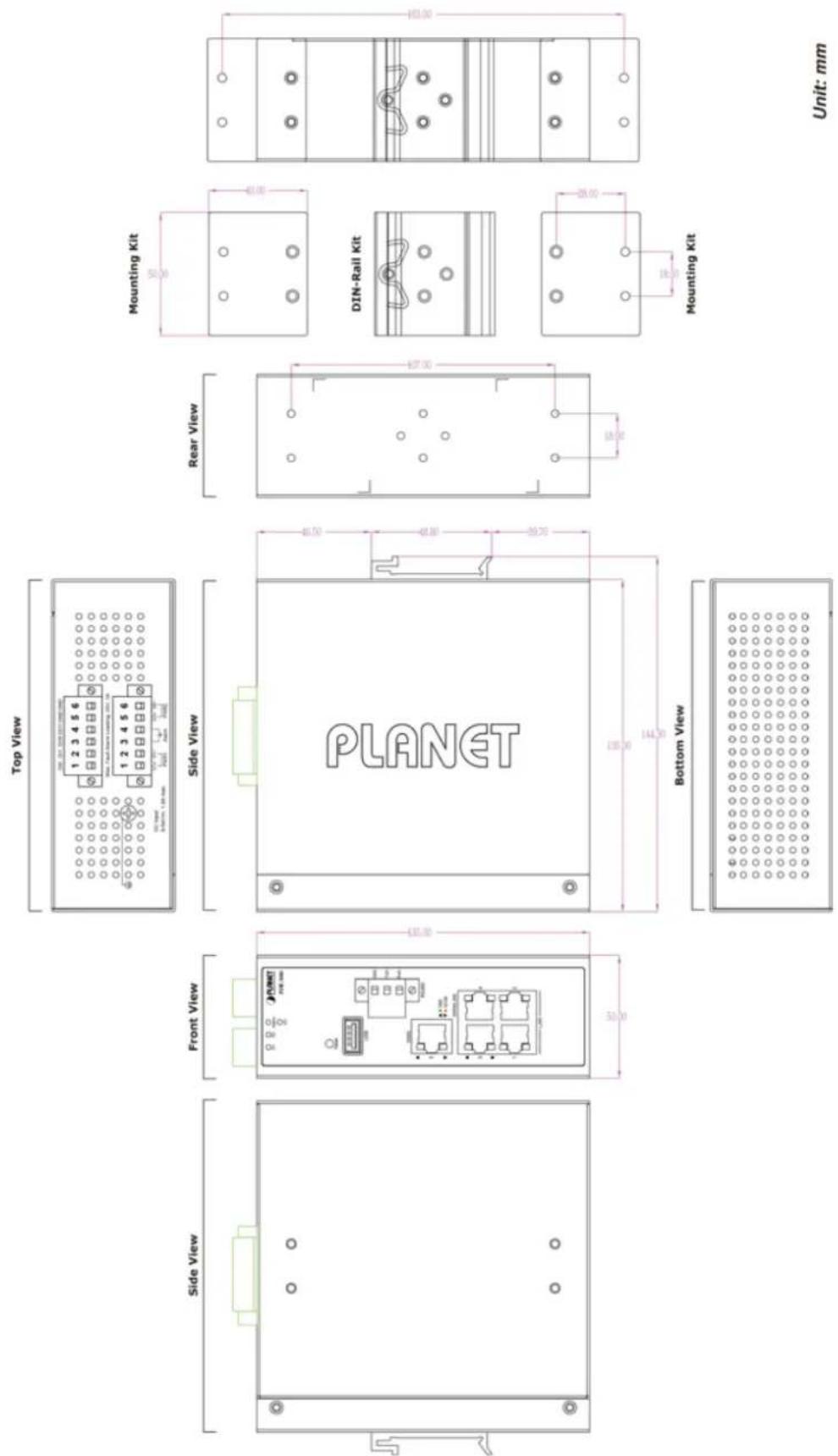
IVR-300W Dimensions

IVR-300W Dimensions

2.2 Hardware Installation
This section describes how to install the Industrial Gateway. There are three methods to install the Industrial Gateway -- DIN-rail mounting, wall mounting and side wall mounting. Basic knowledge of networking is assumed.
Please read the following sections and perform the procedures in the order being presented. (The device shown on this chapter is just a representation of the said device.)
2.2.1 DIN-rail Mounting
Step 1: Lightly slide the DIN-rail into the track.

natural_image
Hand holding a black electronic device with red arrows pointing to its side, mounted on a wall (no visible text or symbols)Step 2: Check whether the DIN-rail is tightly on the track.
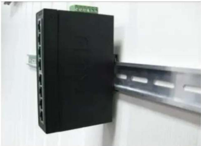
natural_image
Black electronic device with multiple ports mounted on a metal bracket (no visible text or symbols)Step 3: Connect your device to hub / switch.
A. Connect one end of a standard network cable to the LAN port (port 1) of the device.
B. Connect the other end of the cable to the hub / switch.

The UTP Category 5, 5e or 6 network cabling with RJ45 tips is recommended.
Step 4: Connect your device to internet.
A. Connect one end of a standard network cable to the WAN port (port 5) of the device.
B. Connect the other end of the cable to the LAN port of ISP network device (such as a modem).

If there is only one line connected to the outer network in your network environment, it is suggested that you use WAN port (port 5).
Step 5: Power on the device. When the device receives power, the Power LED should remain solid Green.
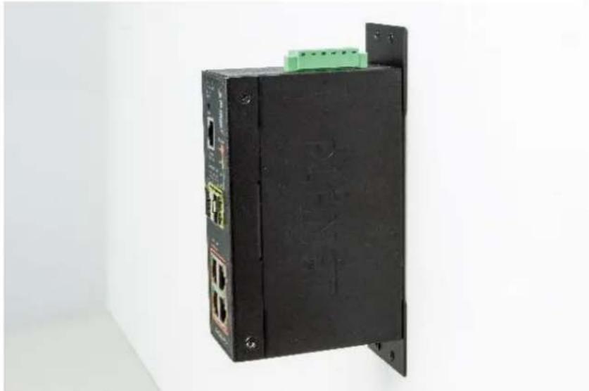
2.2.2 Wall Mount Plate Mounting
To install the Industrial Gateway on the wall, please follow the instructions below.
Step 1: Remove the DIN-rail from the Industrial Gateway. Use the screwdriver to loosen the screws to remove the DIN-rail.
Step 2: Place the wall-mount plate on the rear panel and use the screwdriver to screw the wall mount plate tightly on the Industrial Gateway.
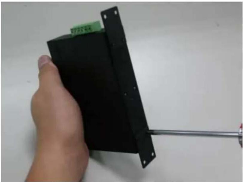
natural_image
Hand holding a black electronic device with a metal rod extending from it, against a plain white background (no text or symbols visible)Step 3: Use the hook holes at the corners of the wall mount plate to hang the Industrial Gateway on the wall.
natural_image
Black industrial electronic device with ports and a green connector, mounted on a wall against a plain white background (no visible text or symbols)Step 4: To remove the wall mount plate, reverse the steps above.
Step 5: Proceed with Steps 3, 4 and 5 in Section 2.2.1 DIN-rail Mounting to connect the network cabling and power on the device.
2.2.3 Side Wall Mount Plate Mounting
To install the Industrial Gateway on the wall, please follow the instructions below.
Step 1: Remove the DIN-rail from the Industrial Gateway. Use the screwdriver to loosen the screws to remove the DIN-rail.
Step 2: Place the wall-mount plate on the side panel and use the screwdriver to screw the wall mount plate tightly on the Industrial Gateway.

natural_image
Close-up of hands using a screwdriver to adjust or install electronic components on a black plastic base (no text or symbols visible)Step 3: Use the hook holes at the corners of the wall mount plate to hang the Industrial Gateway on the wall.

natural_image
Black industrial electronic device labeled 'PLAET' with green connector, mounted on a wall (no readable text beyond label)Step 4: To remove the wall mount plate, reverse the steps above.
Step 5: Proceed with Steps 3, 4 and 5 in Section 2.2.1 DIN-rail Mounting to connect the network cabling and power on the device.
2.2.4 Wi-Fi Antenna Installation
(For IVR-300W only)
Step 1: Fasten the two dual-band antennas to the antenna connectors on the front panel of the IVR-300W.
Step 2: You can bend the antennas to fit your actual needs.

Figure 2-2: IVR-300W Front Panel
Chapter 3. Preparation
Before getting into the device's web UI, user has to check the network setting and configure PC's IP address.
3.1 Requirements
User is able to confirm the following items before configuration:
- Please confirm the network is working properly; it is strongly suggested to test your network connection by connecting your computer directly to ISP.
- Suggested operating systems: Windows 7 / 8 / 10.
- Recommended web browsers: IE / Firefox / Chrome.
3.2 Setting TCP/IP on your PC
The default IP address of the VPN Gateway is 192.168.1.1, and the DHCP Server is on. Please set the IP address of the connected PC as DHCP client, and the PC will get IP address automatically from the VPN Gateway.
Please refer to the following to set the IP address of the connected PC.
3.2.1 Windows 7/8
If you are using Windows 7/8, please refer to the following:
- Click on the network icon from the right side of the taskbar and then click on "Open Network and Sharing Center".

2. Click "Change adapter settings".

3. Right-click on the Local Area Connection and select Properties.

- Select Internet Protocol Version 4 (TCP/IPv4) and click Properties or directly double-click on Internet Protocol Version 4 (TCP/IPv4).

- Select "Use the following IP address" and "Obtain DNS server address automatically", and then click the "OK" button.

3.2.2 Windows 10
If you are using Windows 10, please refer to the following:
- In the search box on the taskbar, type "View network connections", and then select View network connections at the top of the list.

- Right-click on the Local Area Connection and select Properties.

- Select Internet Protocol Version 4 (TCP/IPv4) and click Properties or directly double-click on Internet Protocol Version 4 (TCP/IPv4).

- Select "Use the following IP address" and "Obtain DNS server address automatically", and then click the "OK" button.

3.3 Planet Smart Discovery Utility
For easily listing the Gateway in your Ethernet environment, the search tool -- Planet Smart Discovery Utility -- is an ideal solution.
The following installation instructions are to guide you to running the Planet Smart Discovery Utility.
- Download the Planet Smart Discovery Utility in administrator PC.
- Run this utility as the following screen appears.

Figure: Planet Smart Discovery Utility Screen

If there are two LAN cards or above in the same administrator PC, choose a different LAN card by using the "Select Adapter" tool.
- Press the "Refresh" button for the currently connected devices in the discovery list as the screen shows below:

Figure: Planet Smart Discovery Utility Screen
-
This utility shows all necessary information from the devices, such as MAC address, device name, firmware version, and device IP subnet address. It can also assign new password, IP subnet address and description to the devices.
-
After setup is completed, press the "Update Device", "Update Multi" or "Update All" button to take effect. The functions of the 3 buttons above are shown below:
■ Update Device: use current setting on one single device.
■ Update Multi: use current setting on choose multi-devices.
■ Update All: use current setting on whole devices in the list.
The same functions mentioned above also can be found in "Option" tools bar.
-
To click the "Control Packet Force Broadcast" function, it allows you to assign a new setting value to the device under a different IP subnet address.
-
Press the "Connect to Device" button and the Web login screen appears.
Press the "Exit" button to shut down the Planet Smart Discovery Utility.
Chapter 4. Web-based Management
This chapter provides setup details of the device's Web-based Interface.
4.1 Introduction
The device can be configured with your Web browser. Before configuring, please make sure your PC is under the same IP segment with the device.
4.2 Logging in to the VPN Gateway
Refer to the steps below to configure the VPN Gateway:
Step 1. Connect the IT administrator's PC and VPN Gateway's LAN port (port 1) to the same hub / switch, and then launch a browser to link the management interface address which is set to http://192.168.1.1 by default.

The DHCP server of the VPN Gateway is enabled. Therefore, the LAN PC will get IP from the VPN Gateway. If user needs to set IP address of LAN PC manually, please set the IP address within the range between 192.168.1.2 and 192.168.1.254 inclusively, and assigned the subnet mask of 255.255.255.0.
Step 2. The browser prompts you for the login credentials. (Both are "admin" by default.)
Default IP address: 192.168.1.1
Default user name: admin
Default password: admin
Default 2.4GHz SSID: PLANET_2.4G (for IVR-300W)
Default 5GHz SSID: PLANET_5G (for IVR-300W)

Administrators are strongly suggested to change the default admin and password to ensure system security.
Web Login Screen as below:

Please follow the wizard to do the first-time account modification.
The password must contain 8\~31 characters, including upper case, lower case, numerals and other symbols

Figure 4.2-1 Account Modification
After modifying the new account and password, the main screen appears as shown below:
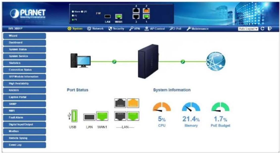
Figure 4.2-2 Web Main Screen
Now, you can use the Web management interface to continue the Security Gateway management or manage the Security Gateway by console interface. Please refer to the user's manual for more.
Administrators are strongly suggested to change the default password and Wi-Fi SSID on the first login to safeguard system security.

- For security reason, please change and memorize the new password after this first setup.
- Only accept command in lowercase letter under web interface.
4.3 Main Web Page
After a successful login, the main web page appears. The web main page displays the web panel, main menu, function menu, and the main information in the center as shown below

Figure 4.3-1 Main Web Page
Web Panel
The web panel displays the device's ports as shown below.

Figure 4.3-2 Web Panel
| Object | Icon | Function |
| Ethernet port |  | To indicate the port without the RJ45 plug-in. |
 | To indicate network data is sending or receiving. | |
 | To indicate the PoE is in use. (IVR-300FP only) | |
| PoE Consumption |  | To indicate the current PoE consumption. (IVR-300FP only) |
| SFP port |  | To indicate the port with the Fiber plug-in. (IVR-300FP only) |
 | To indicate network data is sending or receiving (IVR-300FP only) |
Main Menu
The main menu displays the product name, function menu, and main information in the center. Via the Web management, the administrator can set up the device by selecting the functions those listed in the function menu and button as shown below.

Figure 4.3-3 Function Menu
| Object | Description |
| System | Provides System information of the Gateway. |
| Network | Provides WAN, LAN and network configurations of the Gateway. |
| Security | Provides Firewall and security configurations of the Gateway. |
| VPN | Provides VPN configuration of the Gateway. |
| AP Control | Provides AP Control configuration of the VPN Security Gateway |
| PoE | Provides PoE Management configuration of industrial wall-mount Gigabit router. (IVR-300FP only) |
| Wireless | Provides wireless configuration of the VPN Security Gateway (IVR-300W only) |
| Maintenance | Provides firmware upgrade and setting file restore/backup configuration of the Gateway. |
Auto Logout ▼


Figure 4.3-4 Function Button
| Object | Description |
 | Click the "Refresh button" to refresh the current web page. |
 | Click the "Logout button" to log out the web UI of the Gateway. |
4.4 System
Use the System menu items to display and configure basic administrative details of the Gateway. The System menu as shown below provides the following features to configure and monitor system.
| Wizard |
| Dashboard |
| System Status |
| System Service |
| Statistics |
| Connection Status |
| SFP Module Information |
| High Availability |
| RADIUS |
| Captive Portal |
| SNMP |
| NMS |
| Fault Alarm |
| Digital Input/Output |
| Modbus |
| Remote Syslog |
| Event Log |
Figure 4.4-1 System Menu
| Object | Description |
| Wizard | The Wizard will guide the user to configuring the Gateway easily and quickly. |
| Dashboard | The overview of system information includes connection, port, and system status. |
| System Status | Display the status of the system, Device Information, LAN and WAN. |
| System Service | Display the status of the system, Secured Service and Server Service |
| Statistics | Display statistics information of network traffic of LAN and WAN. |
| Connection Status | Display the DHCP client table and the ARP table |
| SFP Module Information | Display the physical or operational status of an SFP module via the SFP Module Information page (IVR-300FP only) |
| High Availability | Enable/Disable High Availability on VPN Security Gateway |
| RADIUS | Enable/Disable RADIUS on VPN Security Gateway |
| Captive Portal | Enable/Disable Captive Portal on VPN Security Gateway |
| SNMP | Display SNMP system information |
| NMS | Enable/Disable NMS on VPN Security Gateway |
| Fault Alarm | One relay output for power failure. Alarm relay current carry ability |
| Digital Input/Output | Digital Input/Output Control Configuration page |
| Modbus | Configure the Modbus TCP Mode on this page |
| Remote Syslog | Enable Captive Portal on VPN Security Gateway |
| Event Log | Display Event Log information |
4.4.1 Wizard
The Wizard will guide the user to configuring the Gateway easily and quickly. There are different procedures in different operation modes. According to the operation mode you switch to, please follow the instructions below to configure the Gateway via Setup Wizard as shown below

flowchart
graph LR
    A["1 Account"] --> B["2 LAN"]
    B --> C["3 WAN"]
    C --> D["4 Security Settings"]
    D --> E["5 Setup Completed"]
Figure 4.4-2 Setup Wizard
Step 1: Account Modification
Set up the Username and Password for the Account Modification as shown below.

flowchart
graph LR
    A["1 Account"] --> B["2 LAN"]
    B --> C["3 WAN"]
    C --> D["4 Security Settings"]
    D --> E["5 Setup Completed"]
The password must contain 8\~31 characters, including upper case, lower case, numerals and other symbols
Figure 4.4-3 Account Modification
Step 2: LAN Interface
Set up the IP Address and Subnet Mask for the LAN interface as shown below.

Figure 4.4-4 Setup Wizard – LAN Configuration
| Object | Description |
| IP Address | Enter the IP address of your VPN Security Gateway The default is 192.168.1.1. |
| Subnet Mask | An address code that determines the size of the network. Normally use 255.255.255.0 as the subnet mask. |
| DHCP Server | By default, the DHCP Server is enabled.If user needs to disable the function, please uncheck the box. |
| Start IP Address | By default, the start IP address is 192.168.1.100.Please do not set it to the same IP address of the VPN Security Gateway |
| Maximum DHCP Users | By default, the maximum DHCP users are 101, which means the VPN Security Gateway will provide DHCP client with IP address from 192.168.1.100 to 192.168.1.200 when the start IP address is 192.168.1.100. |
| Next | Press this button to the next step. |
| Cancel | Press this button to undo any changes made locally and revert to previously saved values. |
Step 3: WAN Interface
The VPN Security Gateway supports two access modes on the WAN side as shown in below.

Figure 4.4-5 Setup Wizard – WAN Configuration (IVR-100/IVR-300/IVR-300W)
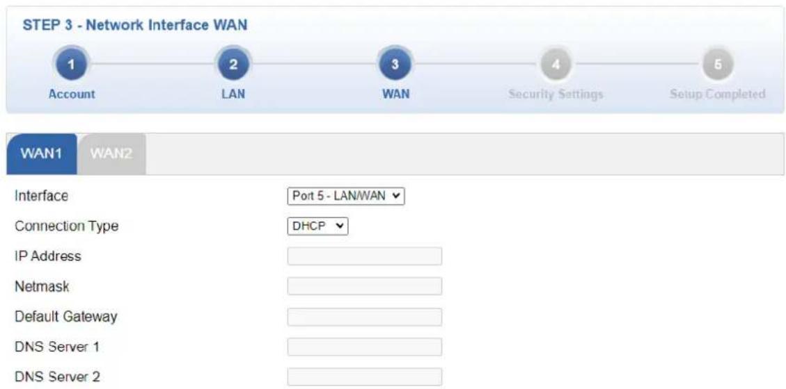
Figure 4.4-6 Setup Wizard – WAN Configuration (IVR-300FP Only)
Mode 1 -- Static IP
Select Static IP Address if all the Internet port's IP information is provided to you by your ISP. You will need to enter the IP Address, Netmask, Default Gateway and DNS Server provided to you by your ISP. Each IP address entered in the fields must be in the appropriate IP form, which are four octets separated by a dot (x.x.x.x). The VPN Security Gateway will not accept the IP address if it is not in this format. The setup is shown below.

Figure 4.4-7 WAN Interface Setup – Static IP Setup
| Object | Description |
| IP Address | Enter the IP address assigned by your ISP. |
| Netmask | Enter the Netmask assigned by your ISP. |
| Default Gateway | Enter the Gateway assigned by your ISP. |
| DNS Server | The DNS server information will be supplied by your ISP. |
| Next | Press this button for the next step. |
| Previous | Press this button for the previous step. |
| Cancel | Press this button to undo any changes made locally and revert to previously saved values. |
Mode 2 -- DHCP Client
Select DHCP Client to obtain IP Address information automatically from your ISP. The setup is shown below.

Figure 4.4-8 WAN Interface Setup - DHCP Setup
Step 4: Wireless Setting
(For IVR-300W only)
Set up the Wireless Settings as shown below.

Figure 4.4-9 Setup Wizard – Wireless Setting
| Object | Description |
| 2.4G Wireless Status | Allows user to enable or disable 2.4G Wi-Fi |
| Wireless Name (SSID) | It is the wireless network name. The default 2.4G SSID is “PLANET_2.4G” |
| Hide SSID | Allows user to enable or disable SSID |
| Bandwidth | Select the operating channel width, “20MHz” or “40MHz” |
| Channel | It shows the channel of the CPE. Default 2.4GHz is channel 6. |
| Encryption | Select the wireless encryption. The default is “Open” |
| Wi-Fi Multimedia | Enable/Disable WMM (Wi-Fi Multimedia ) function |
| 5G Wireless Status | Allows user to enable or disable 5G Wi-Fi |
| Wireless Name (SSID) | It is the wireless network name. The default 5G SSID is “PLANET_5G” |
| Hide SSID | Allows user to enable or disable SSID |
| Bandwidth | Select the operating channel width, “20MHz” or “40MHz” or “80MHz” |
| Channel | It shows the channel of the CPE. Default 5GHz is channel 36. |
| Encryption | Select the wireless encryption. The default is “Open” |
| Wi-Fi Multimedia | Enable/Disable WMM (Wi-Fi Multimedia ) function |
Step 5: Security Setting
Set up the Security Settings as shown the setup is shown below.

line
STEP 5 - Security Settings | Setting | Option | Value | | :--- | :--- | :--- | | Account | Enable | ○ Disable | | Account | Enable | ○ Disable | | LAN | Enable | ○ Disable | | LAN | Enable | ○ Disable | | WAN | Enable | ○ Disable | | WAN | Enable | ○ Disable | | Wireless | Enable | ○ Disable | | Wireless | Enable | ○ Disable | | Security | Enable | ○ Disable | SPI Firewall Block SYN Flood Block ICMP Flood Block WAN Ping Remote Management ● Enable ○ Disable ● Enable ○ Disable ○ Enable ● Disable ○ Enable ● DisableFigure 4.4-10 Setup Wizard – Security Setting
| Object | Description |
| SPI Firewall | The SPI Firewall prevents attack and improper access to network resources.The default configuration is enabled. |
| Block SYN Flood | SYN Flood is a popular attack way. DoS and DDoS are TCP protocols.Hackers like to use this method to make a fake connection that involves the CPU, memory, and so on.The default configuration is enabled. |
| Block ICMP Flood | ICMP is kind of a pack of TCP/IP; its important function is to transfer simple signal on the Internet. There are two normal attack ways which hackers like to use, Ping of Death and Smurf attack.The default configuration is disabled. |
| Block WAN Ping | Enable the function to allow the Ping access from the Internet network.The default configuration is disabled. |
| Remote Management | Enable the function to allow the web server access of the Gateway from the Internet network.The default configuration is disabled. |
Step 6: Setup Completed
The page will show the summary of LAN, WAN and Security settings. The setup is shown below.

Figure 4.4-11 Setup Wizard – Setup Completed
| Object | Description |
| Finish | Press this button to save and apply changes. |
| Previous | Press this button for the previous step. |
4.4.2 Dashboard
The dashboard provides an overview of system information including connection, port, and system status. The setup is shown below.
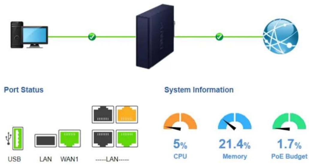
flowchart
graph LR
    A["Port Status"] --> B["Network Port"]
    B --> C["System Information"]
    C --> D["CPU 5%"]
    C --> E["Memory 21.4%"]
    C --> F["PoE Budget 1.7%"]
    subgraph Port Status
        G["USB"]
        H["LAN"]
        I["WAN1"]
        J["----LAN----"]
    end
    subgraph System Information
        K["5% CPU"]
        L["21.4% Memory"]
        M["1.7% PoE Budget"]
Figure 4.4-12 Dashboard
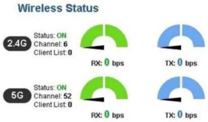
gauge
| Wireless Status | State | RX (bps) | TX (bps) | | --------------- | ----- | -------- | -------- | | 2.4G | ON | 0 | 0 | | 2.4G | Channel | 6 | | | 2.4G | Client List | 0 | | | 5G | ON | 0 | 0 | | 5G | Channel | 52 | | | 5G | Client List | 0 | | | TX | | 0 | 0 | | TX | TX | 0 | 0 |Figure 4.4-13 Dashboard - Wireless
WAN/LAN Connection Status
| Object | Description |
 | The status means WAN is connected to Internet and LAN is connected. |
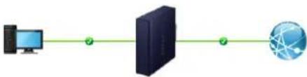 | The status means WAN is disconnected to Internet and LAN is connected. |
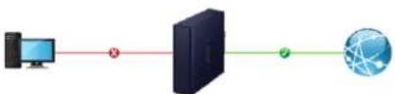 | The status means WAN is connected to Internet and LAN is disconnected. |
Port Status
| Object | Description |
 | Ethernet port is in use. |
 | Ethernet port is not in use. |
 | Ethernet port is PoE-in-use (IVR-300FP Only) |
 | USB port is in use. |
 | USB port is not in use. |
System Information
| Object | Description |
 | Display the CPU loading |
 | |
 | Display the memory usage |
 | |
 | Display the PoE Budget |
| 1.7% | |
| PoE Budget |
Wireless Status
| Object | Description | |
 |  | Wireless is in use. |
| RX: 0 bps | TX: 0 bps | |
 |  | Wireless is not in use. |
| RX: 0 bps | TX: 0 bps | |
4.4.3 Status
This page displays system information as shown below.
Device Information
| Model Name | IVR-300 |
| Firmware Version | v1.2102b220215 |
| Current Time | 2022-04-22 Friday 16:16:32 |
| Running Time | 0 day, 07:31:16 |
| Power Status | PWR1:ON, PWR2:OFF |
| Alarm Status | Normal |
| DI and DO Status | Normal |
WAN1
| MAC Address | 00:30:4F:00:11:23 |
| Connection Type | DHCP |
| Display Name | WAN1 |
| IP Address | |
| Netmask | |
| Default Gateway |
LAN
| MAC Address | 00:30:4F:00:11:22 |
| IP Address | 192.168.1.1 |
| Netmask | 255.255.255.0 |
| DHCP Service | Enable |
| DHCP Start IP Address | 192.168.1.100 |
| DHCP End IP Address | 192.168.1.200 |
| Max DHCP Clients | 101 |
Figure 4.4-14 Status
For IVR-300W Only
2.4GHz WiFi
| Status | ON |
| SSID | PLANET_2.4G |
| Channel | 6 |
| Encryption | Open |
| MAC Address | A8:F7:E0:00:30:5A |
5GHz WiFi
| Status | ON |
| SSID | PLANET_5G |
| Channel | 36 |
| Encryption | WPA2 Personal (TKIP+AES) |
| MAC Address | A8:F7:E0:87:85:5D |
Figure 4.4-15 Status - Wireless (IVR-300W)
4.4.4 System Service
This page displays system service information as shown below.
| Service | |||
| # | State | Service | Detail |
| 1 | Enabled | DHCP Service | DHCP Table: 1 |
| 2 | Disabled | DDNS Service | Not enabled |
| 3 | Enabled | SNMP Service | |
| 4 | Disabled | Quality of Service | |
| 5 | Disabled | High Availability | |
| 6 | Disabled | RADIUS Service | |
| 7 | Disabled | Captive Portal | |
Figure 4.4-16 System Service – Server Service
| # | State | Service | Detail |
| 1 | Enabled | Cybersecurity | TLS 1.2, TLS 1.3 |
| 2 | Enabled | SPI Firewall | |
| 3 | Disabled | MAC Filtering | (Active / Maximum Entries) 0 / 32 |
| 4 | Disabled | IP Filtering | (Active / Maximum Entries) 0 / 32 |
| 5 | Disabled | Web Filtering | (Active / Maximum Entries) 0 / 32 |
| 6 | Disabled | IPSec VPN Server | (Active / Maximum Tunnels) 0 / 16 |
| 7 | Disabled | GRE | (Active / Maximum Tunnels) 0 / 5 |
| 8 | Disabled | PPTP | (Active / Maximum Tunnels) 0 / 91 |
| 9 | Disabled | SSL VPN | (Active / Maximum Tunnels) 0 / 100 |
| 10 | Disabled | L2TP | (Active Tunnels) 0 |
Figure 4.4-17 System Service – Secured Service
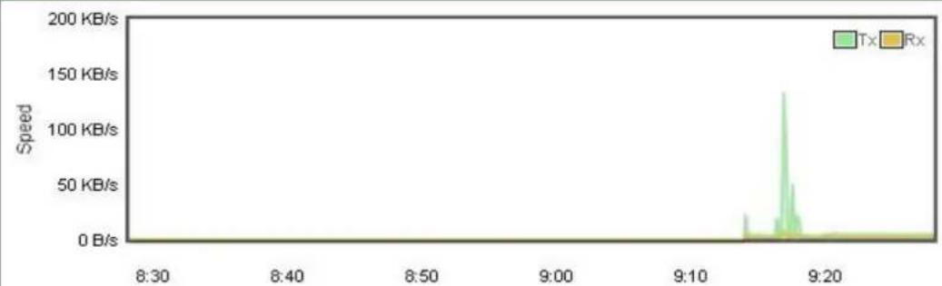
4.4.5 Statistics
This page displays the number of packets that pass through the VPN Security Gateway on the WAN and LAN. The statistics are shown below.
WAN1
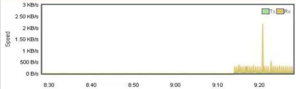
line
| Time | Speed | |-------|-----------| | 8:30 | 0 B/s | | 8:40 | 0 B/s | | 8:50 | 0 B/s | | 9:00 | 0 B/s | | 9:10 | 0 B/s | | 9:20 | 2.50 KB/s | | 9:30 | 0 B/s |LAN
line
| Time | Speed | |-------|-----------| | 8:30 | 0 B/s | | 8:40 | 0 B/s | | 8:50 | 0 B/s | | 9:00 | 0 B/s | | 9:10 | 0 B/s | | 9:20 | 0 B/s |Figure 4.4-18 Statistics
4.4.6 Connection Status
The page will show the DHCP Table and ARP Table. The status is shown below.
DHCP Table
| Name | IP Address | MAC Address | Expiration Time |
| ENM | 192.168.1.154 | 00:05:1b:c5:51:45 | Sat Apr 23 15:39:34 2022 |
ARP Table
| IP Address | MAC Address | ARP Type |
| 192.168.1.154 | 00:05:1b:c5:51:45 | dynamic |
Figure 4.4-19 Connection Status
4.4.7 SFP Module Information
This page shows the operational status, such as the transceiver type, speed, wavelength, optical output power, optical input power, temperature, laser bias current and transceiver supply voltage in real time. The SFP Module Information page is shown below.
| SFP Module Information | ||||||||
| Type | Speed | Wave Length(nm) | Distance(m) | Temperature(C) | Voltage(V) | Current(mA) | Tx power(dBm) | Rx power(dBm) |
| 1000Base-LX | 1000-Base | 1310 | 10000 | 39.0588 | 3.3112 | 18.9760 | -6.3451 | -36.9897 |
Figure 4.4-20 SFP Module Information
| Object | Description |
| Type | Display the type of current SFP module; the possible types are:■ 1000BASE-SX■ 1000BASE-LX |
| Speed | Display the speed of current SFP module; the speed value or description is obtained from the SFP module. Different vendors' SFP modules might show different speed information. |
| Wave Length (nm) | Display the wavelength of current SFP module; the wavelength value is obtained from the SFP module. Use this column to check if the wavelength values of two nodes match while the fiber connection fails. |
| Distance (m) | Display the support distance of current SFP module; the distance value is obtained from the SFP module. |
| Temperature (C)– SFP DDM Module Only | Display the temperature of current SFP DDM module; the temperature value is gotten from the SFP DDM module. |
| Voltage (V)– SFP DDM Module Only | Display the voltage of current SFP DDM module; the voltage value is gotten from the SFP DDM module. |
| Current (mA)– SFP DDM Module Only | Display the ampere of current SFP DDM module; the ampere value is gotten from the SFP DDM module. |
| TX power (dBm)– SFP DDM Module Only | Display the TX power of current SFP DDM module; the TX power value is gotten from the SFP DDM module. |
| RX power (dBm)– SFP DDM Module Only | Display the RX power of current SFP DDM module; the RX power value is gotten from the SFP DDM module. |
4.4.8 High Availability
High Availability (HA) is a redundant system that two IVR VPN Security Gateways can be set up in a master/slave configuration. The master VPN Security Gateway provides the Internet connection but, in the case of hardware or WAN connectivity failure, the slave (backup) VPN Security Gateway automatically takes over Internet connection. It provides redundant hardware and software that make the system available despite failures.
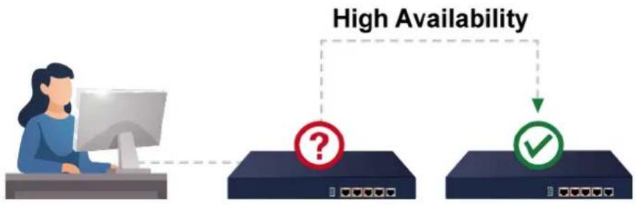
flowchart
graph TD
    A["Computer"] --> B{High Availability?}
    B --> C["Device 1"]
    B --> D{High Availability?}
    D --> E["Device 2"]
    D --> F["Device 3"]
The page will show the High Availability configuration. The High Availability page is shown below.
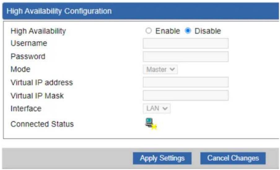
Figure 4.4-21 High Availability
| Object | Description |
| High Availability | Disable or enable the High Availability function.The default configuration is disabled. |
| Username | Create the username for the HA. |
| Password | Create the password for the HA. |
| Mode | Choose Master or Slave role. |
| Virtual IP Address | Assign an IP address as a virtual IP. |
| Virtual Mask | Assign a mask address as a virtual mask. |
| Interface | Use interface. |
| Connection Status | Display the HA status. |
4.4.9 RADIUS
Remote Authentication Dial-In User Service (RADIUS) is a security authentication client/server protocol that supports authentication, authorization and accounting.

flowchart
graph TD
    A["Device 1"] -->|1| B["Server"]
    C["Device 2"] -->|5| B
    D["Device 3"] -->|6| B
    B -->|1| E["User Interface"]
    B -->|5| F["User Interface"]
    style A fill:#f9f,stroke:#333
    style C fill:#f9f,stroke:#333
    style D fill:#f9f,stroke:#333
    style B fill:#ccf,stroke:#333
    style E fill:#cff,stroke:#333
    style F fill:#cff,stroke:#333
The RADIUS Server page is shown below.
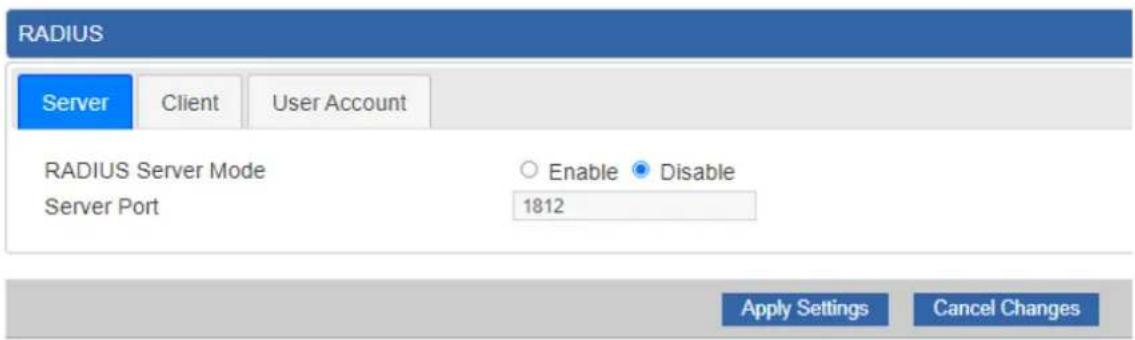
Figure 4.4-22 RADIUS Server
| Object | Description |
| RADIUS | Disable or enable the RADIUS function.The default configuration is disabled. |
| Server Port | UDP port number for authentication |
The RADIUS client page is shown below.

Figure 4.4-23 RADIUS Client
| Object | Description |
| Name | Describe client's name |
| Client IP address | Describe client's IP address |
| Secret Key | The RADIUS server and client share a secret key that is used to authenticate the messages sent between server and client. |
| Description | Describe client's information |
4.4.10 Captive Portal
Captive portal service gives the ability to organize a public (or guest) Wi-Fi zone with user authorization. A captive portal is the authorization page that forcibly redirects users who connect to the public network before accessing the Internet.
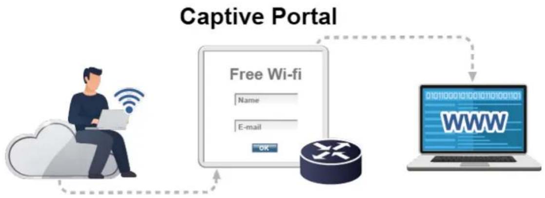
flowchart
graph TD
    A["User with WiFi"] --> B["Free Wi-fi"]
    B --> C["Router"]
    C --> D["WWW"]
    D --> E["Internet"]
    style A fill:#f9f,stroke:#333
    style B fill:#ccf,stroke:#333
    style C fill:#cfc,stroke:#333
    style D fill:#fcc,stroke:#333
    style E fill:#ffc,stroke:#333
The Captive portal page is shown below.

Figure 4.4-24 Captive Portal
| Object | Description |
| Captive portal | Disable or enable the Captive portal function.The default configuration is disabled. |
| Interface | Choose subnet interface■ LAN Subnet 1■ LAN Subnet 2■ LAN Subnet 3■ LAN Subnet 4 |
| Authentication Type | Support local RADIUS server |
4.4.11 SNMP
This page provides SNMP setting as shown below.
SNMP
| SNMP | Enable Disable |
| SNMP Versions | SNMP v1,v2c |
| Read Community | public |
| Write Community | private |
| Engine ID | |
| SNMP v3 Security Level | AuthPRiv |
| SNMP v3 User Name | |
| SNMP v3 Auth Protocol | MD5 |
| SNMP v3 Auth Password | |
| SNMP v3 Privacy Protocol | DES |
| SNMP v3 Privacy Password |
System Identification
| System Name | IVR-300 |
| System Description | |
| System Location | |
| System Contact | sales@planet.com.tw |
Figure 4.4-25 SNMP Configuration Page
| Object | Description |
| Enable SNMP | Disable or enable the SNMP function.The default configuration is enabled. |
| Read/Write Community | Allows entering characters for SNMP Read/Write Community of the VPN Security Gateway |
| System Name | Allows entering characters for system name of the VPN Security Gateway |
| System Location | Allows entering characters for system location of the VPN Security Gateway |
| System Contact | Allows entering characters for system contact of the VPN Security Gateway |
| Apply Settings | Press this button to save and apply changes. |
| Cancel Changes | Press this button to undo any changes made locally and revert to previously saved values. |
4.4.12 NMS
The IVR series can support both NMS controller and CloudViewer Sever for remote management.
PLANET's NMS Controller is a Network Management System that can monitor all kinds of deployed network devices, such as managed switches, media converters, routers, smart APs, VoIP phones, IP cameras, etc., compliant with the SNMP Protocol, ONVIF Protocol and PLANET Smart Discovery utility. The CloudViewer is a free networking service just for PLANET products. This service provides simplified network monitoring and real-time network status. Working with PLANET CloudViewer app, user can easily check network status, device information, and port and PoE statuses from Internet.
NMS Configuration screen appears as shown below.

Figure 4.4-26 NMS Configuration Page
The NMS Controller – LAN Configuration screen appears as shown below.
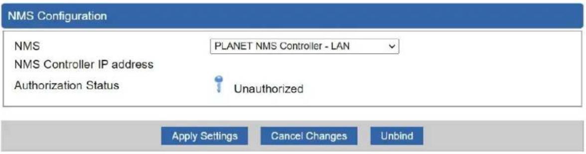
Figure 4.4-27 NMS Controller – LAN Configuration Page
| Object | Description |
| NMS Controller IP address | The IP address of NMS Controller |
| Authorization Status | Indicate the authorization status of the switch to NMS Controller |
The CloudViewer Server – Internet screen appears as shown below.

Figure 4.4-28 CloudViewer Server – Internal Configuration Page
| Object | Description |
| The email registered on CloudViewer Server | |
| • Password | The password of your CloudViewer account |
| • Connection Status | Indicate the status of connecting CloudViewer Server |
4.4.13 Fault Alarm
The IVR series supports a Fault Alarm feature which can alert the users when there is something wrong with the device. With this ideal feature, the users would not have to waste time finding where the issue is. It will help to save time and human resource.
Fault Alarm Feature

This page provides fault alarm setting as shown below.
| Fault Alarm Control Configuration | |
| Fault Alarm Output | |
| Enable | Enable |
| Record | System Log |
| Event | Power Fail Port Fail |
| Power Alarm | PWR1 PWR2 |
| Port Alarm | 1 2 3 4 5 |
Figure 4.4-29 Fault Alarm
| Object | Description |
| Enable | Controls whether Fault Alarm is enabled. |
| Record | Controls whether Record is sending System log or SMS. |
| Event | Controls whether Port Failure or Power Failure or both is/are detected. |
| Power Alarm | Controls whether faulty PWR1 or faulty PWR2 or both is/are detected. |
| Port Alarm | Controls which port or all is/are detected for fault. |
4.4.14 Digital Input / Output
The IVR-300/IVR-300W supports Digital Input and Digital Output on its upper panel. This external alarm enables users to use Digital Input to detect and log external device status (such as door intrusion detector), and send event alarm to the administrators. The Digital Output could be used to alarm the administrators if the IVR-300/IVR-300W port shows link down, link up or power failure.
Digital Input


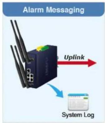
flowchart
graph TD
    A["Alarm Messaging"] --> B["Network"]
    B --> C["Uplink"]
    B --> D["System Log"]
Digital Output


This page provides Digital Input / Output setting as shown below.
| Digital Input/Output Control Configuration | |||
| Digital Input 0 | Digital Input 1 | ||
| Enable | Enable | Enable | Enable |
| DI Condition | High to Low | DI Condition | High to Low |
| Event Description | Event Description | ||
| Action | System Log | Action | System Log |
| Digital Output 0 | Digital Output 1 | ||||||||||
| Enable | Enable | Enable | Enable | ||||||||
| Action | Power Fail | Port Fail | DI 0 | DI 1 | Action | Power Fail | Port Fail | DI 0 | DI 1 | ||
| DO Condition | High to Low | DO Condition | High to Low | ||||||||
| Power Alarm | PWR1 | PWR2 | Power Alarm | PWR1 | PWR2 | ||||||
| Port Fail Alarm | 1 | 2 | 3 | 4 | 5 | Port Fail Alarm | 1 | 2 | 3 | 4 | 5 |
Figure 4.4-30 Digital Input / Output
| Object | Description |
| Enable | Check the Enable checkbox to enable Digital Input / output function. Uncheck the Enable checkbox to disable Digital input / output function. |
| Condition | As Digital Input: Allows user to select High to Low or Low to High. This means a signal received by system is from High to Low or from Low to High. It will trigger an action that logs a customized message or issue the message from the switch.As Digital Output: Allows user to select High to Low or Low to High. This means that when the switch is power-failed or port-failed, the system will issue a High or Low signal to an external device such as an alarm. |
| Event Description | Allows user to set a customized message for Digital Input function alarm. |
| Action | As Digital Input: Allows user to record alarm message to System log, syslog or issues out via SNMP Trap or SMTP.By default, SNMP Trap and SMTP are disabled. Please enable them first if you want to issue alarm message via them.As Digital Output: Allows user to monitor an alarm from port failure, power failure, Digital Input 0 (DI 0) and Digital Input 1(DI 1) which mean if Digital Output has detected these events, then Digital Output would be triggered according to the setting of Condition. |
| Power Alarm | Allows user to choose which power module that needs to be monitored. |
| Port Alarm | Allows user to choose which port that needs to be monitored. |
4.4.15 Modbus
The IVR-300/IVR-300W provides a feature that can convert the Serial RS485 communication to IP networking. Ethernet signal allows two types of segments to connect easily, efficiently and inexpensively. The solution helps users and SIs save expenses as there is no need to replace the existing serial equipment and software system.
Convert Serial Communication to IP Networking
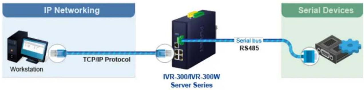
flowchart
graph LR
    A["Workstation"] -->|TCP/IP Protocol| B["IVR-300/IVR-300W Server Series"]
    B -->|Serial bus RS485| C["Serial Devices"]
This page provides Modbus Configuration setting as shown below.
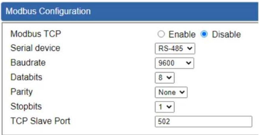
Figure 4.4-31 Modbus Configuration
| Object | Description |
| Modbus TCP | Indicates the Modbus TCP mode operation. Possible modes are:Enabled: Enable Modbus TCP mode operation level: Disabled: Disable Modbus TCP mode operation. |
| Serial device | Set up the Modbus Serial device to RS-485 |
| Baudrate | Select the Modbus Baudrate to 300 ~ 115200 |
| Databits | Set up the Modbus Databits to 8 |
| Parity | Set up the Modbus Parity to None, Odd or Even |
| Stopbits | Set up the Modbus Stopbits to 1 or 2 |
| TCP Slave Port | Set up the Modbus TCP Slave Port. |
4.4.16 Remote Syslog
This page provides remote syslog setting as shown below.

Figure 4.4-32 Remote Syslog Configuration
| Object | Description |
| • Enable | Controls whether remote syslog is enabled |
| • Syslog Server IP | Indicates the IPv4 host address of syslog server |
| • Port Destination | Configure port for remote syslog |
4.5 Network
The Network function provides WAN, LAN and network configuration of the VPN Security Gateway as shown below.

Figure 4.5-1 Network Menu
| Object | Description |
| Priority | Allows setting priority of WAN interface. |
| WAN | Allows setting WAN interface. |
| WAN Advanced | Allows setting WAN Advanced settings. |
| LAN | Allows setting LAN interface. |
| Multi-Subnet | Allows setting Multi-Subnet1 ~ Subnet4 interface. |
| VLAN | Disable or enable the VLAN function.The default configuration is disabled. |
| UPnP | Disable or enable the UPnP function.The default configuration is disabled. |
| Routing | Allows setting Route. |
| RIP | Disable or enable the RIP function.The default configuration is disabled. |
| OSPF | Disable or enable the OSPF function.The default configuration is disabled. |
| IGMP | Disable or enable the IGMP function.The default configuration is disabled. |
| IPv6 | Allows setting IPv6 WAN interface. |
| DHCP | Allows setting DHCP Server. |
| DDNS | Allows setting DDNS and PLANET DDNS. |
| MAC AddressClone | Allows setting WAN MAC Address Clone. |
4.5.1 Priority
This page provides SD WAN priority setting as shown below.
| SD WAN Priority | |||||
| No. | Group Name | Path | Services | Active | Action |
Figure 4.5-2 SD WAN Priority List

Figure 4.5-3 SD WAN Configuration
| Object | Description |
| Active | ■ Enable / Disable the Active |
| Group Name | ■ Setting the Group Name. |
| Path | ■ Setting the SD-WAN To / To SD-WAN |
| Service Port or Group | ■ Setting the Service Port or Group Border Gateway Protocol |
4.5.2 WAN
This page is used to configure the parameters for Internet network which connects to the WAN port of the VPN Security Gateway as shown below. Here you may select the access method by clicking the item value of WAN access type.
WAN1 Configuration
| Interface | Port 5 - LAN/WAN |
| Display Name | WAN1 |
| Connection Type | DHCP |
| IP Address | |
| Netmask | |
| Default Gateway | |
| DNS Server 1 | |
| DNS Server 2 |
WAN2 Configuration
| WAN | ○Enable ●Disable |
| Interface | Port 6 - SFP |
| Display Name | WAN2 |
| Connection Type | DHCP ▼ |
| IP Address | |
| Netmask | |
| Gateway | |
| DNS Server 1 | |
| DNS Server 2 |
Figure 4.5-4 WAN Configuration
| Object | Description | |
| WAN Access Type | Please select the corresponding WAN Access Type for the Internet, and fill out the correct parameters from your local ISP in the fields which appear below. | |
| Static | Select Static IP Address if all the Internet ports' IP information is provided to you by your ISP (Internet Service Provider). You will need to enter the IP address, Netmask, Gateway, and DNS Server provided to you by your ISP.Each IP address entered in the fields must be in the appropriate IP form, which are four octets separated by a dot (x.x.x.x). The VPN Security Gateway will not accept the IP address if it is not in this format.IP AddressEnter the IP address assigned by your ISP.NetmaskEnter the Subnet Mask assigned by your ISP.GatewayEnter the Gateway assigned by your ISP.DNS ServerThe DNS server information will be supplied by your ISP. | |
| DHCP | Select DHCP Client to obtain IP Address information automatically from your ISP. | |

Note
WAN IP, whether obtained automatically or specified manually, should NOT be on the same IP net segment as the LAN IP; otherwise, the VPN Security Gateway will not work properly. In case of emergency, press the hardware-based "Reset" button.
4.5.3 WAN Advanced
This page is used to configure the advanced parameters for Internet area network which connects to the WAN port of your VPN Security Gateway as shown below. Here you may change the setting for Load Balance Weight, Detect Interval, Detect Linkup Threshold, etc.
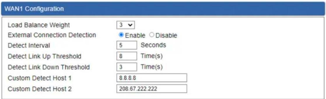
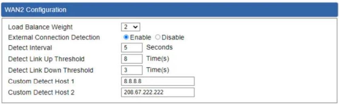
Figure 4.5-5 WAN Advanced Configuration
| Object | Description |
| Load Balance Weight | Load Balance Weight allows you to set a relative weight (from 1 - 10) for each WAN port. |
| External Connection Detection | Enable to detect the status of WAN connection. |
| Detect Interval | Set the detect interval as you need.The recommended value is 5 (default). |
| Detect Link Up Threshold | Set the times for detecting link up.The recommended value is 8 (default). |
| Detect Link Down Threshold | Set the times for detecting link down.The recommended value is 3 (default). |
| Custom Detect Host | The host is used to check whether the internet connection is alive or not. |
4.5.4 LAN
This page is used to configure the parameters for local area network which connects to the LAN port of your VPN Security Gateway as shown below. Here you may change the settings for IP address, subnet mask, DHCP, etc.

Figure 4.5-6 LAN Configuration
| Object | Description |
| IP Address | The LAN IP address of the VPN Security Gateway and default is 192.168.1.1. |
| Net Mask | Default is 255.255.255.0. |
4.5.5 Multi-Subnet
This page provides multi-subnet setting as shown below.

Figure 4.5-7 Multi-Subnet Configuration
4.5.6 VLAN
Please refer to the following sections for the details as shown below.

Figure 4.5-8 VLAN Configuration
4.5.7 UPnP
Please refer to the following sections for the details as shown below.

Figure 4.5-9 UPnP Configuration
4.5.8 Routing
Please refer to the following sections for the details as shown below.
| Routing config list | |||||||
| Number | Type | Destination | Netmask | Gateway | Interface | Comment | Action |
| Current Routing table in the system | |||||||
| Number | Destination | Netmask | Gateway | Interface | |||
| 1 | 0.0.0.0 | 0.0.0.0 | 192.168.0 180 | LOCAL | |||
| 2 | 0.0.0.0 | 0.0.0.0 | 192.168.1 18 | WAN1 | |||
| 3 | 0.0.0.0 | 0.0.0.0 | 192.168.1 19 | WAN2 | |||
| 4 | 192.168.0.0 | 255.255.255.0 | 0.0.0.0 | LAN | |||
| 5 | 192.168.1.0 | 255.255.255.0 | 0.0.0.0 | WAN1 | |||
| 6 | 192.168.1.0 | 255.255.255.0 | 0.0.0.0 | WAN2 | |||
Figure 4.5-10 Routing Table Configuration
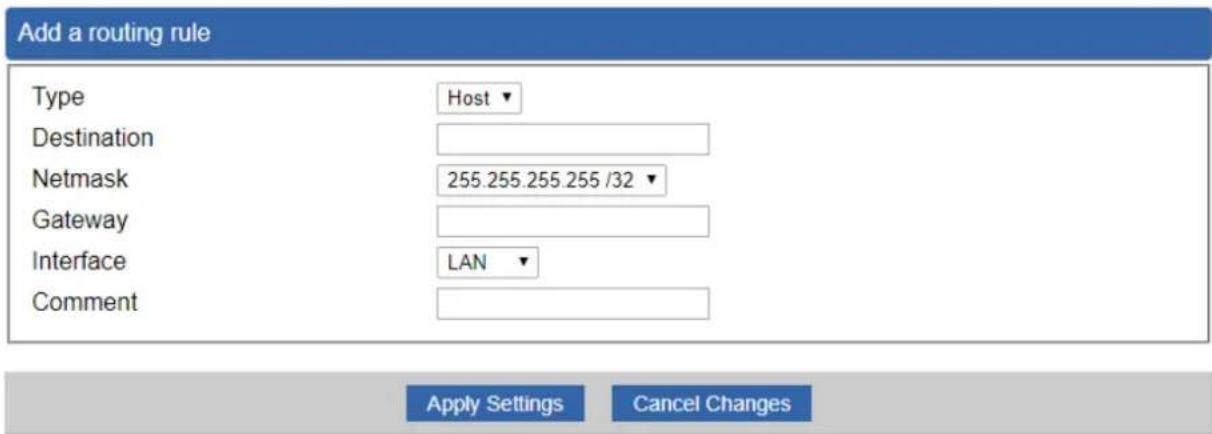
Figure 4.5-11 Routing Setup
Routing tables contain a list of IP addresses. Each IP address identifies a remote VPN Security Gateway (or other network gateway) that the local VPN Security Gateway is configured to recognize. For each IP address, the routing table additionally stores a network mask and other data that specifies the destination IP address ranges that remote device will accept.
| Object | Description |
| Type | There are two types: Host and Net.When the Net type is selected, user does not need to input the Gateway. |
| Destination | The network or host IP address desired to access. |
| Net Mask | The subnet mask of destination IP. |
| Gateway | The gateway is the router or host's IP address to which packet is sent. It must be the same network segment with the WAN or LAN port. |
| Interface | Select the interface that the IP packet must use to transmit out of the router when this route is used. |
| Comment | Enter any words for recognition. |
4.5.9 RIP
Please refer to the following sections for the details as shown below.

Figure 4.5-12 RIP Configuration
4.5.10 OSPF
Please refer to the following sections for the details as shown below.
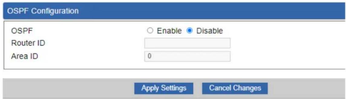
Figure 4.5-13 OSPF Configuration
4.5.11 IGMP
Please refer to the following sections for the details as shown below.
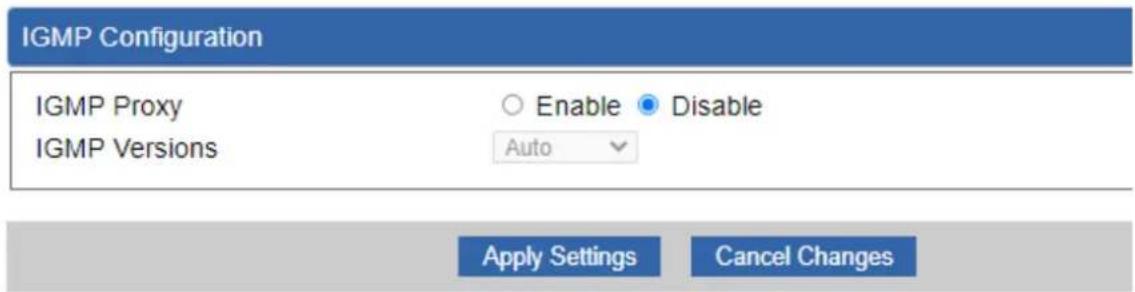
Figure 4.5-14 IGMP Configuration
4.5.12 IPv6
This page is used to configure parameter for IPv6 internet network which connects to WAN port of the VPN Security Gateway as shown below. It allows you to enable IPv6 function and set up the parameters of the VPN Security Gateway's WAN. In this setting you may change WAN connection type and other settings.
IPv6 - WAN1
| Connection Type | DHCP |
| IPv6 Address | |
| Subnet Prefix Length | 64 |
| Default Gateway | |
| IPv6 DNS Server 1 | |
| IPv6 DNS Server 2 |
IPv6 - WAN2
| Connection Type | DHCP |
| IPv6 Address | |
| Subnet Prefix Length | 64 |
| Default Gateway | |
| IPv6 DNS Server 1 | |
| IPv6 DNS Server 2 |
Figure 4.5-15 IPv6 – WAN Configuration
IPv6 - LAN
| Type | Delegate Prefix from WAN ○ Static |
| Static Address | |
| Subnet Prefix Length | 64 |
DHCPv6
| Address Assign | ● Stateless ○ Stateful ○ Passthrough ○ Disable |
Figure 4.5-16 IPv6 – LAN Configuration
| Object | Description |
| Connection Type | Select IPv6 WAN type either by using DHCP or Static. |
| IPv6 Address | Enter the WAN IPv6 address. |
| Subnet Prefix Length | Enter the subnet prefix length. |
| Default Gateway | Enter the default gateway of the WAN port. |
4.5.13 DHCP
The DHCP service allows you to control the IP address configuration of all your network devices. When a client (host or other device such as networked printer, etc.) joins your network it will automatically get a valid IP address from a range of addresses and other settings from the DHCP service. The client must be configured to use DHCP; this is something called "automatic network configuration" and is often the default setting. The setup is shown below.

Figure 4.5-17 DHCP Configuration
| Object | Description |
| DHCP Service | By default, the DHCP Server is enabled, meaning the VPN Security Gateway will assign IP addresses to the DHCP clients automatically.If user needs to disable the function, please set it as disable. |
| Start IP Address | By default, the start IP address is 192.168.1.100.Please do not set it to the same IP address of the VPN Security Gateway |
| Maximum DHCP Users | By default, the maximum DHCP users are 101, meaning the VPN Security Gateway will provide DHCP client with IP address from 192.168.1.100 to 192.168.1.200 when the start IP address is 192.168.1.100. |
| Set DNS | By default, it is set as Automatically, and the DNS server is the VPN Security Gateway's LAN IP address.If user needs to use specific DNS server, please set it as Manually, and then input a specific DNS server. |
| Primary/Secondary | Input a specific DNS server. |
| WINS | Input a WINS server if needed. |
| Lease Time | Set the time for using one assigned IP. After the lease time, the DHCP client will need to get new IP addresses from the VPN Security GatewayDefault is 1440 minutes. |
| Domain Name | Input a domain name for the VPN Security GatewayDefault is Planet. |
4.5.14 DDNS
The VPN Security Gateway offers the DDNS (Dynamic Domain Name System) feature, which allows the hosting of a website, FTP server, or e-mail server with a fixed domain name (named by yourself) and a dynamic IP address, and then your friends can connect to your server by entering your domain name no matter what your IP address is. Before using this feature, you need to sign up for DDNS service providers such as PLANET DDNS (http://www.planetddns.com) and set up the domain name of your choice.
PLANET DDNS website provides a free DDNS (Dynamic Domain Name Server) service for PLANET devices. Whether the IP address used on your PLANET device supporting DDNS service is fixed or dynamic, you can easily connect the devices anywhere on the Internet with a meaningful or easy-to-remember name you gave. PLANET DDNS provides two types of DDNS services. One is PLANET DDNS and the other is PLANET Easy DDNS as shown below.
PLANET DDNS
For example, you've just installed a PLANET IP camera with dynamic IP like 210.66.155.93 in the network. You can name this device as "Mycam1" and register a domain as Mycam1.planetddns.com at PLANET DDNS (http://www.planetddns.com). Thus, you don't need to memorize the exact IP address but just the URL link: Mycam1.planetddns.com.
PLANET Easy DDNS
PLANET Easy DDNS is an easy way to help user to get your Domain Name with just one click. You can just log in to the Web Management Interface of your devices, say, your VPN Security Gateway, and check the DDNS menu and just enable it. You don't need to go to http://www.planetddns.com to apply for a new account. Once you enabled the Easy DDNS, your PLANET Network Device will use the format PLxxxxxx where xxxxxx is the last 6 characters of your MAC address that can be found on the Web page or bottom label of the device. (For example, if the VPN Security Gateway's MAC address is A8-F7-E0-81-96-C9, it will be converted into pt8196c9.planetddns.com)

Figure 4.5-18 DDNS Configuration
| Object | Description |
| DDNS Service | By default, the DDNS service is disabled.If user needs to enable the function, please set it as enable. |
| Interface | User is able to select the interface for DDNS service.By default, the interface is WAN 1. |
| DDNS Type | There are three options:1. PLANET DDNS: Activate PLANET DDNS service.2. DynDNS: Activate DynDNS service.3. NOIP: Activate NOIP service.Note that please first register with the DDNS service and set up the domain name of your choice to begin using it. |
| Easy DDNS | When the PLANET DDNS service is activated, user is able to select to enable or disable Easy DDNS.When this function is enabled, DDNS hostname will appear automatically. User doesn't go to http://www.planetddns.com to apply for a new account. |
| User Name | The user name is used to log into DDNS service. |
| Password | The password is used to log into DDNS service. |
| Host Name | The host name as registered with your DDNS provider. |
| Interval | Set the update interval of the DDNS function. |
| Update Status | Show the connection status of the DDNS function. |
4.5.15 MAC Address Clone
Clone or change the MAC address of the WAN interface. The setup is shown below.

Figure 4.5-19 MAC Address Clone for WAN
| Object | Description |
| Clone WAN MAC | Set the function as enable or disable. |
| MAC Address | Input a MAC Address, such as A8:F7:E0:00:06:62. |
4.6 Security
The Security menu provides Firewall, Access Filtering and other functions as shown below. Please refer to the following sections for the details.
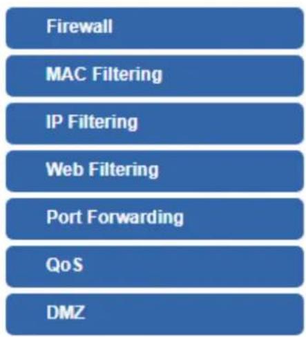
Figure 4.6-1 Security menu
| Object | Description |
| Firewall | Allows setting DoS (Denial of Service) protection as enable. |
| MAC Filtering | Allows setting MAC Filtering. |
| IP Filtering | Allows setting IP Filtering. |
| Web Filtering | Allows setting Web Filtering. |
| Port Range Forwarding | Allows setting Port Forwarding. |
| QoS | Allows setting QoS. |
| DMZ | Allows setting DMZ. |
4.6.1 Firewall
A "Denial-of-Service" (DoS) attack is characterized by an explicit attempt by hackers to prevent legitimate users of a service from using that service. The VPN Security Gateway can prevent specific DoS attacks as shown below.
Firewall Protection
SPI Firewall
● Enable ○ Disable
DDoS
Block SYN Flood
Block FIN Flood
Block UDP Flood
Block ICMP Flood
Block IP Teardrop Attack
Block Ping of Death
Block TCP packets with SYN and FIN Bits set
Block TCP packets with FIN Bit set but no ACK Bit set
Block TCP packets without Bits set
● Enable ○ Disable
○ Enable ● Disable
○ Enable ● Disable
○ Enable ● Disable
○ Enable ● Disable
○ Enable ● Disable
○ Enable ● Disable
○ Enable ● Disable
○ Enable ● Disable
30 Packets/Second
30 Packets/Second
30 Packets/Second
5 Packets/Second
System Security
Block WAN Ping
HTTP Port
HTTPS Port
Remote Management
○ Enable ● Disable
80
443
○ Enable ● Disable
Temporarily block when login failed more than
IP blocking period
Blocked IP
0 (0 means no limit)
0 minute(s) (0 means permanent blocking)
0.0.0.0
NATALGs
FTP ALG
TFTP ALG
RTSP ALG
H.323 ALG
RTSPALG
H.323 ALG
SIP ALG
- Enable ○ Disable
● Enable ○ Disable
○ Enable ● Disable
○ Enable ● Disable
○ Enable ● Disable
○ Enable ● Disable
○ Enable ● Disable
Figure 4.6-2 Firewall
| Object | Description |
| SPI Firewall | The SPI Firewall prevents attack and improper access to network resources.The default configuration is enabled. |
| Block SYN Flood | SYN Flood is a popular attack way. DoS and DDoS are TCP protocols. Hackers like to use this method to make a fake connection that involves the CPU, memory, and so on.The default configuration is enabled. |
| Block FIN Flood | If the function is enabled, when the number of the current FIN packets is beyond the set value, the VPN Security Gateway will start the blocking function immediately.The default configuration is disabled. |
| Block UDP Flood | If the function is enabled, when the number of the current UPD-FLOOD packets is beyond the set value, the VPN Security Gateway will start the blocking function immediately.The default configuration is disabled. |
| Block ICMP Flood | ICMP is kind of a pack of TCP/IP; its important function is to transfer simple signal on the Internet. There are two normal attack ways which hackers like to use, Ping of Death and Smurf attack.The default configuration is disabled. |
| IP TearDrop | If the function is enabled, the VPN Security Gateway will block Teardrop attack that is targeting on TCP/IP fragmentation reassembly codes. |
| Ping Of Death | If the function is enabled, the VPN Security Gateway will block Ping of Death attack that aims to disrupt a targeted machine by sending a packet larger than the maximum allowable size causing the target machine to freeze or crash. |
| Block WAN Ping | Enable the function to allow the Ping access from the Internet network.The default configuration is disabled. |
| Remote Management | Enable the function to allow the web server access of the VPN Security Gateway from the Internet network.The default configuration is disabled. |
4.6.2 MAC Filtering
Entries in this table are used to restrict certain types of data packets from your local network or Internet through the VPN Security Gateway Use of such filters can be helpful in securing or restricting your local network as shown below.
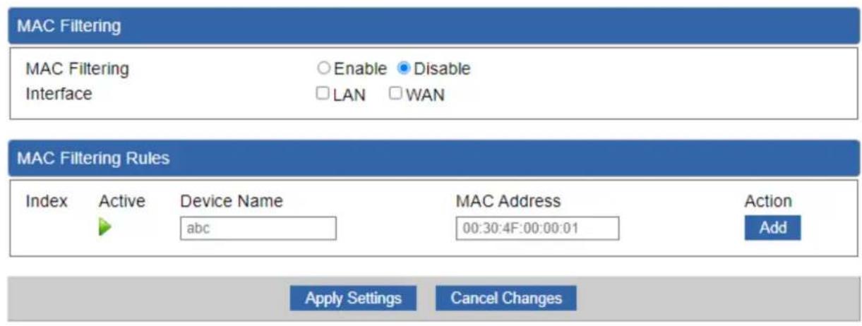
Figure 4.6-3 MAC Filtering Configuration
| Object | Description |
| Enable MAC Filtering | Set the function as enable or disable.When the function is enabled, the VPN Security Gateway will block traffic of the MAC address on the list. |
| Interface | Select the function works on LAN, WAN or both. If you want to block a LAN device's MAC address, please select LAN, vice versa. |
| MAC Address | Input a MAC address you want to control, such as A8:F7:E0:00:06:62. |
| Add | When you input a MAC address, please click the “Add” button to add it to the list. |
| Remove | If you want to remove a MAC address from the list, please click on the MAC address, and then click the “Remove” button to remove it. |
| Remove All | If you want to remove all MAC addresses from the list, please click the “Remove All” button to remove all. |
4.6.3 IP Filtering
IP Filtering is used to deny LAN users from accessing the public IP address on internet as shown below. To begin blocking access to an IP address, enable IP Filtering and enter the IP address of the web site you wish to block.

Figure 4.6-4 IP Filtering Configuration
| Object | Description |
| IP Filtering | Set the function as enable or disable. |
| Add IP Filtering Rule | Go to the Add Filtering Rule page to add a new rule. |

Figure 4.6-5 IP Filter Rule Setting
| Object | Description |
| Enable | Set the rule as enable or disable. |
| Source IP Address | Input the IP address of LAN user (such as PC or laptop) which you want to control. |
| Anywhere (of source IP Address) | Check the box if you want to control all LAN users. |
| Destination IP Address | Input the IP address of web site which you want to block. |
| Anywhere (of destination IP Address) | Check the box if you want to control all web sites, meaning the LAN user can't visit any web site. |
| Destination Port | Input the port of destination IP Address which you want to block.Leave it as blank if you want to block all ports of the web site. |
| Protocol | Select the protocol type (TCP, UDP or all).If you are unsure, please leave it to the default all protocol. |
4.6.4 Web Filtering
Web filtering is used to deny LAN users from accessing the internet as shown below. Block those URLs which contain keywords listed below.

Figure 4.6-6 Web Filtering Configuration
| Object | Description |
| Web Filtering | Set the function as enable or disable. |
| Add Web Filtering Rule | Go to the Add Web Filtering Rule page to add a new rule. |

Figure 4.6-7 Web Filtering Rule Setting
| Object | Description |
| Active | Set the rule as enable or disable. |
| Filter Keyword | Input the URL address that you want to filter, such as www.yahoo.com. |
4.6.5 Port Forwarding
Entries in this table allow you to automatically redirect common network services to a specific machine behind the NAT firewall as shown below. These settings are only necessary if you wish to host some sort of server like a web server or mail server on the private local network behind your VPN Security Gateway's NAT firewall.

Figure 4.6-8 Port Forwarding Configuration
| Object | Description |
| Port Forwarding | Set the function as enable or disable. |
| Add Port Forwarding Rule | Go to the Add Port Forwarding Rule page to add a new rule. |

Figure 4.6-9 Port Forwarding Rule Setting
| Object | Description |
| Rule Name | Enter any words for recognition. |
| Protocol | Select the protocol type (TCP, UDP or both). If you are unsure, please leave it to the default both protocols. |
| External Service Port | Enter the external ports you want to control. For TCP and UDP services, enter the beginning of the range of port numbers used by the service. If the service uses a single port number, enter it in both the start and finish fields. |
| Virtual Server IP Address | Enter the local IP address. |
| Internal Service Port | Enter local ports you want to control. For TCP and UDP Services, enter the beginning of the range of port numbers used by the service. If the service uses a single port number, enter it in both the start and finish fields. |
4.6.6 QoS
Please refer to the following sections for the details as shown below.


| Upstream Bandwidth | ||
| Priority | Maximum Bandwidth | Bandwidth Value |
| Premium | 100 % | WAN1 0 Kbps |
| WAN2 0 Kbps | ||
| Express | 100 % | WAN1 0 Kbps |
| WAN2 0 Kbps | ||
| Standard | 100 % | WAN1 0 Kbps |
| WAN2 0 Kbps | ||
| Bulks | 100 % | WAN1 0 Kbps |
| WAN2 0 Kbps | ||
| Downstream Bandwidth | ||
| Priority | Maximum Bandwidth | Bandwidth Value |
| Premium | 100 % | WAN1 0 Kbps |
| WAN2 0 Kbps | ||
| Express | 100 % | WAN1 0 Kbps |
| WAN2 0 Kbps | ||
| Standard | 100 % | WAN1 0 Kbps |
| WAN2 0 Kbps | ||
| Bulks | 100 % | WAN1 0 Kbps |
| WAN2 0 Kbps | ||


Figure 4.6-10 QoS Configuration
4.6.7 DMZ
A Demilitarized Zone is used to provide Internet services without sacrificing unauthorized access to its local private network as shown below. Typically the DMZ host contains devices accessible to Internet traffic, such as Web (HTTP) servers, FTP servers, SMTP (e-mail) servers and DNS servers.
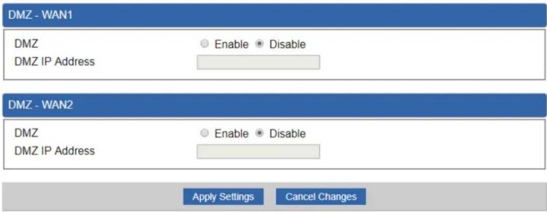
Figure 4.6-11 DMZ Configuration
| Object | Description |
| DMZ | Set the function as enable or disable. If the DMZ function is enabled, it means that you set up DMZ at a particular computer to be exposed to the Internet so that some applications/software, especially Internet/online game can have two way connections. |
| DMZ IP Address | Enter the IP address of a particular host in your LAN which will receive all the packets originally going to the WAN port/Public IP address above. |
4.7 VPN
To obtain a private and secure network link, the VPN (Virtual Private Network) Security Gateway is capable of establishing VPN connections. When used in combination with remote client authentication, it links the business' remote sites and users, conveniently providing the enterprise with an encrypted network communication method. By allowing the enterprise to utilize the Internet as a means of transferring data across the network, it forms one of the most effective and secure options for enterprises to adopt in comparison to other methods.

flowchart
graph LR
    A["Industrial VPN Security Gateway"] --> B["Failover Connection"]
    B --> C["Content Filtering"]
    C --> D["VPN Tunnel"]
The VPN menu provides the following features as shown below.
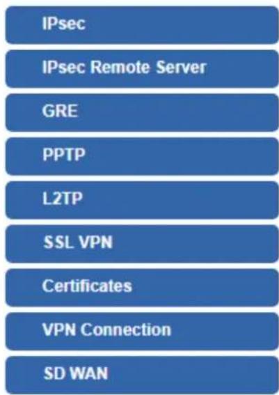
Figure 4.7-1 VPN Menu
| Object | Description |
| IPsec | Allows setting IPsec function. |
| IPsec Remote Server | Disable or enable the IPsec Remote Server function.The default configuration is disabled. |
| GRE | Allows setting GRE function. |
| PPTP | Allows setting PPTP function. |
| L2TP | Allows setting L2TP function. |
| SSL VPN | Allows setting SSL VPN function. |
| Certificates | Download System CA Certificate |
| VPN Connection | Allows checking VPN Connection Status. |
4.7.1 IPSec
IPSec (IP Security) is a generic standardized VPN solution. IPSec must be implemented in the IP stack which is part of the kernel. Since IPSec is a standardized protocol it is compatible to most vendors that implement IPSec. It allows users to have an encrypted network session by standard IKE (Internet Key Exchange). We strongly encourage you to use IPSec only if you need to because of interoperability purposes. When IPSec lifetime is specified, the device can randomly refresh and identify forged IKE's during the IPSec lifetime.
This page will allow you to modify the user name and passwords as shown below.

Figure 4.7-2 IPsec Configuration
| Object | Description |
| Add IPSec Tunnel | Go to the Add IPSec Tunnel page to add a new tunnel. |

IKE Setting
Phase 1
IKE
v1
○v2
Connection Type
Ma
in ○Aggressive
ISAKMP
AES
128 bit)
SHA1
↓
DH Group
2 (1024)
IKE SA Lifetime
3
The Ground Truth image displays a single, solid horizontal line. According to Rule 2 (UNDERSCORE & LINE RULES), this is a stylistic or background line, not a placeholder underscore. Therefore, the OCR result must ignore it and output nothing or only meaningful text. The provided OCR content is "____", which consists of four underscores. This is an incorrect interpretation of the line as a placeholder, violating the rule that stylistic lines must be ignored. The OCR has hallucinated underscores where none should exist based on the GT's visual context. Hence, the OCR result is inconsistent with the Ground Truth.
hours
Phase 2
ESP
AES
128 bit
√
SHA1
m = 311
ESP Keylife
1
The Ground Truth image displays a single, solid horizontal line. According to Rule 2 (UNDERSCORE & LINE RULES), this is a stylistic or background line, not a placeholder underscore. Therefore, the OCR result must ignore it and output nothing or only meaningful text. The provided OCR content is "____", which consists of four underscores. This is an incorrect interpretation of the line as a placeholder, violating the rule that stylistic lines must be ignored. The OCR has hallucinated underscores where none should exist based on the GT's visual context. Hence, the OCR result is inconsistent with the Ground Truth.
hours
Perfect Forward Secrecy (PFS)
○Ye
s N
。
Figure 4.7-3 IPSec Tunnel
| Object | Description |
| IPSec Tunnel Enable | Check the box to enable the function. |
| Tunnel Name | Enter any words for recognition. |
| Interface | This is only available for host-to-host connections and specifies to which interface the host is connecting.1. WAN 1.2. WAN 2. |
| Local Network | The local subnet in CIDR notation. For instance, "192.168.1.0". |
| Local Netmask | The netmask of this VPN Security Gateway |
| Remote IP Address | Input the IP address of the remote host. For instance, "210.66.1.10". |
| Remote Network | The remote subnet in CIDR notation. For instance, "210.66.1.0". |
| Remote Netmask | The netmask of the remote host. |
| Dead Peer Detection | Set up the detection time of DPD (Dead Peer Detection).By default, the DPD detection's gap is 30 seconds, over 150 seconds to think that is the broken line.When VPN detects opposite party reaction time, the function will take one of the actions: "Hold" stand for the system will retain IPSec SA "Clear" stand for the tunnel will clean away and waits for the new sessions, "Restart" will delete the IPSec SA and reset VPN tunnel. |
| Preshare Key | Enter a pass phrase to be used to authenticate the other side of the tunnel. Should be the same as the remote host. |
| IKE | Select the IKE (Internet Key Exchange) version. |
| Connection Type | 1. Main.2. Aggressive. |
| ISAKMP | It provides the way to create the SA between two PCs. The SA car access the encoding between two PCs, and the IT administrator can assign to which key size or Preshare Key and algorithm to use. The SA comes in many connection ways.1. AES: All using a 128-bit, 192-bit and 256-bit key. AES is a commonly seen and adopted nowadays.2. 3DES: Triple DES is a block cipher formed from the DES cipher by using it three times. It can achieve an algorithm up to 168 bits.3. SHA1: The SHA1 is a revision of SHA. It has improved the shortcomings of SHA. By producing summary hash values, it can achieve an algorithm up to 160 bits.4. SHA2: Either 256, 384 or 512 can be chosen5. MD5 Algorithm: MD5 processes a variably long message into a fixed-length output of 128 bits.6. DH Group: Either 1, 2, 5, 14, 15, 16, 17, or 18 can be chosen. |
| IKE SA Lifetime | You can specify how long IKE packets are valid. |
| ESP | It offers AES, 3 DES, SHA 1, SHA2, and MD5.1. AES: All using a 128-bit, 192-bit and 256-bit key. AES is a commonly seen and adopted nowadays.2. 3DES: Triple DES is a block cipher formed from the DES cipher by using it three times. It can achieve an algorithm up to 168 bits.3. SHA1: The SHA1 is a revision of SHA. It has improved the shortcomings of SHA. By producing summary hash values,i can achieve an algorithm up to 160 bits.4. SHA2: Either 256, 384 or 512 can be chosen.5. MD5 Algorithm: MD5 processes a variably long message into a fixed-length output of 128 bits. |
| ESP Keylife | You can specify how long ESP packets are valid. |
| Perfect Forward Secrecy (PFS) | Set the function as enable or disable. |
4.7.2 IPsec Remote Server
This section assists you in setting the IPsec Remote Server Configuration as shown below.
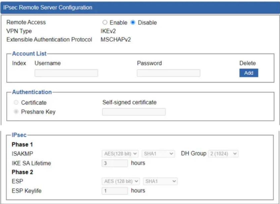
Figure 4.7-4 IPsec Remote Server Configuration
4.7.3 GRE
This section assists you in setting the GRE Tunnel as shown below.

Figure 4.7-5 GRE Tunnel
| Object | Description |
| GRE Tunnel | Set the function as enable or disable. |
| Add GRE Tunnel | Go to the Add GRE Tunnel page to add a new tunnel. |
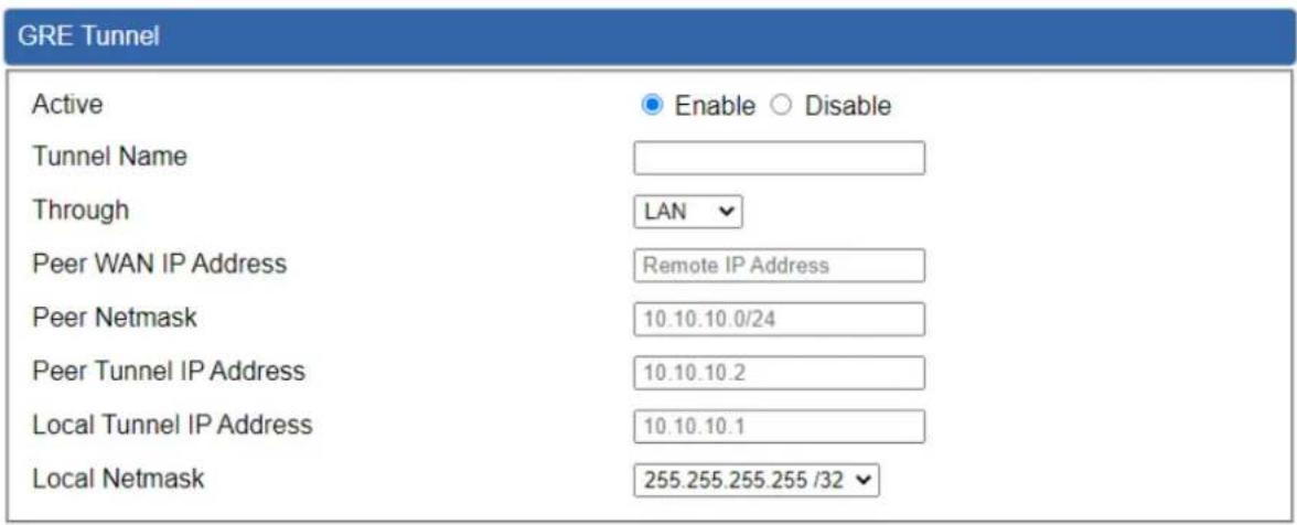
Figure 4.7-6 GRE Tunnel Configuration
| Object | Description |
| Active | Check the box to enable the function. |
| Tunnel Name | Enter any words for recognition. |
| Through | This is only available for host-to-host connections and specifies to which interface the host is connecting.1. LAN.2. WAN 1.3. WAN 2. |
| Peer WAN IP Address | Input the IP address of the remote host. For instance, "210.66.1.10". |
| Peer Netmask | The remote subnet in CIDR notation. For instance, "210.66.1.0/24". |
| Peer Tunnel IP Address | Input the Tunnel IP address of remote host. |
| Local Tunnel IP Address | Input the Tunnel IP address of remote host. |
| Local Netmask | Input the Tunnel IP address of the VPN Security Gateway |
4.7.4 PPTP
Use the IP address and the scope option needs to match the far end of the PPTP server; its goal is to use the PPTP channel technology, and establish Site-to-Site VPN where the channel can have equally good results from different methods with IPSec. The PPTP server is shown in Figure 4-8-6.

Figure 4.7-7 PPTP Server Configuration
| Object | Description |
| PPTP Server | Set the function as enable or disable. |
| Broadcast | Enter any words for recognition. |
| Force MPPE Encryption | Set the encryption as enable or disable. |
| CHAP | Set the authentication as enable or disable. |
| MSCHAP | Set the authentication as enable or disable. |
| MSCHAP v2 | Set the authentication as enable or disable. |
| DNS | When the PPTP client connects to the PPTP server, it will assign the DNS server IP address to client. |
| WINS | When the PPTP client connects to the PPTP server, it will assign the WINS server IP address to client. |
| Server IP Address | Input the IP address of the PPTP Server. For instance, "192.168.10.1". |
| Clients IP Address (Start/End) | When the VPN connection is established, the VPN client will get IP address from the VPN Server. Please set the range of IP Address. For instance, the start IP address is "192.168.10.10", the end IP address is "192.168.10.100". |
| User and Password | Create the username and password for the VPN client. |
4.7.5 L2TP
This section assists you in setting the L2TP Server as shown below.

Figure 4.7-8 L2TP Server Configuration
| Object | Description |
| L2TP Server | Set the function as enable or disable. |
| Server IP Address | Input the IP address of the L2TP Server. For instance, "192.168.50.1". |
| Clients IP Address (Start/End) | When the VPN connection is established, the VPN client will get IP address from the VPN Server. Please set the range of IP Address. For instance, the start IP address is "192.168.50.100", the end IP address is "192.168.50.200". |
| With IPsec | Set the function as enable to make the L2TP work with IPsec encryption. |
| Preshare Key | Enter a pass phrase. |
| User and Password | Create the username and password for the VPN client. |
| Connection Type | 1. Main.2. Aggressive. |
| ISAKMP | It provides the way to create the SA between two PCs. The SA can access the encoding between two PCs, and the IT administrator canassign to which key size or Preshare Key and algorithm to use. The SA comes in many connection ways.1. AES: All using a 128-bit, 192-bit and 256-bit key. AES is a commonly seen and adopted nowadays.2. 3DES: Triple DES is a block cipher formed from the DES cipher by using it three times. It can achieve an algorithm up to 168 bits.3. SHA1: The SHA1 is a revision of SHA. It has improved the shortcomings of SHA. By producing summary hash values, it can achieve an algorithm up to 160 bits.4. SHA2: Either 256, 384 or 512 can be chosen.5. MD5 Algorithm: MD5 processes a variably long message into a fixed-length output of 128 bits.6. DH Group: Either 1, 2, 5, 14, 15, 16, 17, or 18 can be chosen. |
| IKE SA Lifetime | You can specify how long IKE packets are valid. |
| ESP | It offers AES, 3 DES, SHA 1, SHA2, and MD5.1. AES: All using a 128-bit, 192-bit and 256-bit key. AES is a commonly seen and adopted nowadays.2. 3DES: Triple DES is a block cipher formed from the DES cipher by using it three times. It can achieve an algorithm up to 168 bits.3. SHA1: The SHA1 is a revision of SHA. It has improved the shortcomings of SHA. By producing summary hash values,it can achieve an algorithm up to 160 bits.4. SHA2: Either 256, 384 or 512 can be chosen.5. MD5 Algorithm: MD5 processes a variably long message into a fixed-length output of 128 bits. |
| ESP Keylife | You can specify how long ESP packets are valid. |
4.7.6 SSL VPN
This section assists you in setting the SSL Server as shown below.

Figure 4.7-9 SSL Server Configuration
| Object | Description |
| SSL VPN Server | Set the function as enable or disable. |
| Port | Set a port for the SSL Service. Default port is 1194. |
| Tunnel Protocol | Set the protocol as TCP or UDP. |
| Virtual Network Device | Set the Virtual Network Device as TUN or TAP. |
| Interface | User is able to select the interface for SSL service using. |
| VPN Network | The VPN subnet in CIDR notation. For instance, "192.168.20.0". |
| Network Mask | The netmask of the VPN. |
| Encryption Cipher | There are four encryption types: None, AES-128 CBC, AES-192 CBC or AES-256 CBC. |
| Hash Algorithm | There are five types of Hash Algorithm: None, SHA1, SHA1, SHA512 or MD5. |
| Export client.ovpn | Export a configuration for the SSL client. User is able to upload it to VPN client (such as Open VPN software). |
4.7.7 Certificates
This page shows the VPN System Certificates status as shown below.

Figure 4.7-10 System Certificates
4.7.8 VPN Connection
This page shows the VPN connection status as shown below.

Figure 4.7-11 VPN Connection Status
| Object | Description |
| VPN Connection Status | Click the IPSec/GRE/.../SSL VPN bookmark to check the current connection status. |
4.7.9 SD WAN
This page shows the SD WAN Configuration status as shown below.

Figure 4.7-12 SD WAN Configuration
4.8 AP Control
The IVR-300/IVR-300W provides centralized management of PLANET Smart AP series via a user-friendly Web GUI. It's easy to configure AP for the wireless SSID, radio band and security settings. With a four-step configuration process, wireless profiles for different purposes can be simultaneously delivered to multiple APs or AP groups to minimize deployment time, effort and cost.
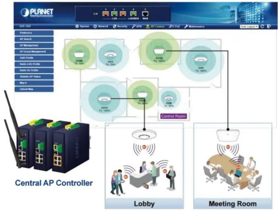
flowchart
graph TD
    A["Control Room"] --> B["Lobby"]
    A --> C["Meeting Room"]
    D["Central AP Controller"] --> E["CH11 Tx: 100%"]
    D --> F["CH12 Tx: 50%"]
    D --> G["CH13 Tx: 100%"]
    D --> H["CH14 Tx: 70%"]
    D --> I["CH15 Tx: 100%"]
    J["Control Room"] --> K["Lobby"]
    J --> L["Meeting Room"]
    M["AP Control"] --> N["CH1 Tx: 100%"]
    M --> O["CH26 Tx: 100%"]
    P["AP Management"] --> Q["CH1 Tx: 70%"]
    P --> R["CH26 Tx: 100%"]
    S["AP Group Management"] --> T["CH1 Tx: 70%"]
    S --> U["CH26 Tx: 100%"]
    V["Radio 2.4G Profile"] --> W["CH1 Tx: 100%"]
    X["Radio SG Profile"] --> Y["CH1 Tx: 100%"]
    Z["Static AP Status"] --> AA["CH1 Tx: 100%"]
    AB["Map II"] --> AC["CH1 Tx: 35%"]
    AD["Upload Map"] --> AE["CH1 Tx: 35%"]
For example, to configure multiple smart APs of the same model, the IVR-300/IVR-300W allows clustering them to a managed group for unified management. According to requirements, wireless APs can be flexibly expanded or removed from a wireless AP group at any time. The AP cluster benefits bulk provision and bulk firmware upgrade through single entry point instead of having to configure settings in each of them separately.
Simplified Cluster Management with 4 Steps

flowchart
graph LR
    A["Step 1\nSearch"] --> B["Step 2\nAdd Profile"]
    B --> C["Step 3\nBatch Provisioning"]
    C --> D["Step 4\nMap It"]
The AP Control menu provides the following features for managing the system as shown below.

Figure 4.8-1 AP Control Menu
| Object | Description |
| Preference | Edit region, RO community, RW community |
| AP Search | Search APs in the same domain |
| AP Management | Config APs IP Address, Subnet Mask, SSID and Radio Profiles |
| AP Group Management | Grouping same model AP |
| SSID Profile | Setup SSID Profile |
| Radio 2.4GHz Profile | Setup Radio 2.4GHz Profiles |
| Radio 5GHz Profile | Setup Radio 5GHz Profiles |
| Statistics AP Status | Show the status of managed APs |
| Map It | Edit the map of AP location and coverage |
| Upload Map | Search APs in the same domain |
4.8.1 Preference
On this page, you can choose the device region of FCC or ETSI. Then edit RO community and RW community for public or private use. Select Apply or Reset. This screenshot is as shown below.
AP Preference

Figure 4.8-2 AP Preference

Device of FCC and device of ETIS cannot be shown at the same time.
4.8.2 AP Search
On this page, you can add new APs in your AP Control System.
Steps to follow:
Step 1. Press the Search button to discover PLANET devices.
Step 2. After waiting for a while, choose which AP you want to add.
Step 3. Press the Apply button to finish addition.

Figure 4.8-3 AP Search of AP Controller

When using AP Search, the AP's IP Address must be the same as WS-Series Switch IP domain.
4.8.3 AP Management
On this page, you can manage your APs, including checking AP online status, configuring AP (IP address, Mask, SSID and Radio profile), rebooting AP, firmware update, and deleting AP in the AP Control system.

Figure 4.8-4 AP Management of AP Controller
Status:
| Object | Description |
| Connection status: online, offline, Wi-Fi disabled | |
| In progress: action in progress | |
| Finished/Successful: action finished and successful. | |
| Failed: action failed. |
Action:
| Object | Description |
| Setting: edit setting and allocate profile to AP | |
| Link: link to the AP's web page | |
| Firmware Update: Upgrade AP's firmware | |
| Reboot: Reboot the AP | |
| Delete: Delete the AP from the control list LED Control: Control the AP's LED. | |
| Mouse-click in a sequential order: LED blink-> LED off-> LED on |

To configure multiple APs at one time, select multiple APs and then choose one of the action icons on the top of the page. The "Link" action is not allowed for multiple APs.

When the setup of AP is done, you need to press the Apply button to complete the setup.
4.8.4 AP Group Management
On the AP Group Management page, you can create AP group and control one or more AP groups.

Figure 4.8-5 AP Group Management of AP Controller
Action:
| Object | Description | |
 | Add new group: Click it to add an AP group. | |
 | Delete selected item: Click it to delete the selected AP group. | |

Figure 4.8-6 AP Group Config of AP Controller
■ Create Group:
- Select AP Model No. you want to Add
- Type AP Group Name and AP Group Description.
- Select AP you want to add in group member setting area and press the Add button.
- Select AP Group SSID profile and Radio Profile.
- Press the Apply button to finish create AP group.

To do profile provisioning to multiple AP groups at one time, select multiple AP groups, and then click the "Apply" button.
The "Link" action is not allowed for multiple APs or AP group.
4.8.5 SSID Profile
On the SSID profile configuration page, enter the value that you preferred and then click "Apply" to save the profile.
| SSID Profile | Filter by SSID Name | 10 (10_16) | ||||||
| Num. | Model No. | SSID Name | SSID Broadcast | Security | Encryption | Client Isolation | Action | |
| 1 | WDAP-850AC | WDAP-850ACP-10F | Disabled | WPA | Personal (Pre-Shared Key) | Enabled | ||
Figure 4.8-7 SSID Profile of AP Controller
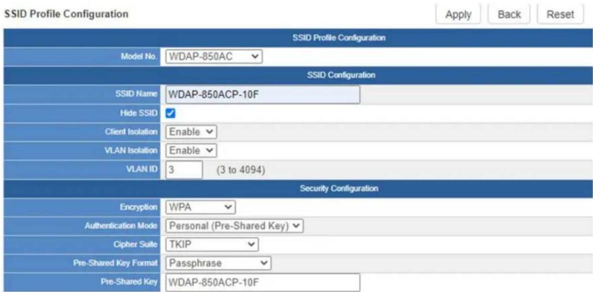
Figure 4.8-8 SSID Profile Configuration of AP Controller
Action:
| Object | Description |
 | Add new profile: Click it to add a new profile. |
 | Delete selected item: Click it to delete the selected profile. |
 | Edit: Click it to edit the profile. |
| [wcg7] | Delete: Click it to delete the single profile. |
4.8.6 Radio 2.4GHz Profile
On the Radio profile configuration page, enter the value that you preferred and then click "Apply" to save the profile.
| Radio Profile 2.4GHz | Filter by Profile Name | 10 (10..8) | |||||||
| Num. | Model No. | Profile Name | Wireless Mode | Channel ID | Channel Bandwidth | Tx Power | Data Rate | Action | |
| 1 | WDAP-850AC | Test 2.4GHz | 11b/g/n mixed mode | Auto | 40MHz | 100% | N/A | ||
Figure 4.8-9 2.4GHz Radio Profile of AP Controller
Action:
| Object | Description |
 | Add new profile: Click it to add a new profile. |
 | Delete selected item: Click it to delete the selected profile. |
 | Edit: Click it to edit the profile. |
 | Delete: Click it to delete the single profile. |
Radio Profile 2.4GHz Configuration

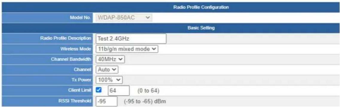
Figure 4.8-10 2.4GHz Radio Profile Configuration of AP Controller
Action:
| Object | Description |
| Apply Button: | Click this button to save the settings. |
| Back Button: | Click this button to return to the previous page. |
| Reset Button: | Click this button to reset all fields to default value. |

Strongly suggest you to keep the values as default except the fields like Channel, Network Mode, Channel Bandwidth, Tx Power, IAPP, and Tx/Rx to prevent any unexpected error or impact on the performance.

WMM Capable is not allowed to be disabled.
4.8.7 Radio 5GHz Profile
On the Radio profile configuration page, enter the value that you preferred and then click "Apply" to save the profile.

Figure 4.8-11 5 GHz Radio Profile of AP Controller
Action:
| Object | Description |
 | Add new profile: Click it to add a new profile. |
 | Delete selected item: Click it to delete the selected profile. |
 | Edit: Click it to edit the profile. |
 | Delete: Click it to delete the single profile. |
Radio Profile 5GHz Configuration


Figure 4.8-12 5 GHz Radio Profile Configuration of AP Controller
Action:
Apply Button: Click this button to save the settings.
Back Button: Click this button to return to the previous page.
Reset Button: Click this button to reset all fields to default value.

-
Strongly suggest you to keep the values as default except the fields like Channel, Network Mode, Channel Bandwidth, Tx Power, IAPP, and Tx/Rx to prevent any unexpected error or impact on the performance.
-
WMM Capable is not allowed to be disabled.
4.8.8 Statistics AP Status
On this page, you can observe the current configuration of all managed APs.
| Num. | Status | MAC Address | IP Address | Model No. | Name | Firmware | AP Group | 2.4GHz SSID Profile | 5GHz SSID Profile | 2.4GHz Radio Profile | 50Hz Radio Profile |
| 1 | a8.17.e0.46.2e.36 | 192.168.0.102 | WDAP-C7200E | WDAP-C7200E-AP-FCC-V3.0-Build20200321122005 | |||||||
| 2 | a8.17.e0.3c.5f.ab | 192.168.0.101 | WNAP-C3220E | WNAP-C3220E-AP-FCC-V3.0-Build20200422115453 | N/A | N/A |
Figure 4.8-13 Statistics AP Status of AP Controller
Filter: You can filter the AP list by entering the keyword in the field next to the magnifier icon. The keyword should be in any context that belongs to the fields of this page.
4.8.9 Map It
On this page you can add managed APs to the actual position against the floor map. This is convenient to user to view and adjust the actual deployment by reference to its real transmission power and channel allocation.

Figure 4.8-14 Upload Map page


Figure 4.8-15 the simulator page of the wireless signal strong of AP
- Click "Scale" to start to reset the map scale.
- Press the set button to draw a line on the map. Fill its physical distance in the blank and press Set or Cancel. For example, in the graph below, set the door width to 0.8 m

Note
You need to upload map image first before bringing managed APs to the actual position.
4.8.10 Upload Map
On this page, the system allows you to upload your floor map to the system.

Figure 4.8-16 Upload Map page

Note
The system allows user to upload up to 10 floor maps.
4.9 Wireless
(For IVR-300W Only)
The IVR-300W is designed with high power amplifier and 2 highly-sensitive antennas which provide stronger signal and excellent coverage even in the wide-ranging or bad environment. With adjustable transmit power option, the administrator can flexibly reduce or increase the output power for various environments, thus reducing interference to achieve maximum performance. Equipped with the next-generation Wi-Fi 6 (802.11ax) wireless network standard, the total bandwidth reaches 1800Mbps, and the 2-stream transmission technology improves the transmission efficiency of multiple devices, making AR/VR/IoT applications smoother. The IEEE 802.11ax also optimizes MU-MIMO (Multi-User MIMO) mechanism to serve multiple devices simultaneously.
The Wireless menu provides the following features as shown below.

Figure 4.9-1 Wireless Menu
| Object | Description |
| 2.4GHz Wi-Fi | Allow to configure 2.4GHz Wi-Fi. |
| 5GHz Wi-Fi | Allow to configure 5GHz Wi-Fi. |
| MAC ACL | Allow configure MAC ACL. |
| Wi-Fi Advanced | Allow to configure advanced setting of Wi-Fi. |
| Wi-Fi Statistics | Display the statistics of Wi-Fi traffic. |
| Connection Status | Display the connection status. |
4.9.1 2.4GHz WiFi
This page allows the user to define 2.4GHz WiFi as shown below.

Figure 4.9-2 2.4GHz WFI Configuration
| Object | Description |
| 2.4GHz WFI | Allows user to enable or disable 2.4GHz Wi-Fi |
| 2.4GHz WFI | It is the wireless network name. The default 2.4GHz SSID is “PLANET_2.4G” |
| 2.4GHz WFI | Allows user to enable or disable SSID |
| 2.4GHz WFI | Select the operating channel width, “20MHz” or “40MHz” |
| 2.4GHz WFI | It shows the channel of the CPE. Default 2.4GHz is channel 6. |
| 2.4GHz WFI | Select the wireless encryption. The default is “Open” |
| 2.4GHz WFI | Enable/Disable WMM (Wi-Fi Multimedia) function |
4.9.2 5GHz WiFi
This page allows the user to define 5GHz Wi-Fi as shown below.

Figure 4.9-3 5 GHz WFI Configuration
| Object | Description |
| Wireless Status | Allows user to enable or disable 5GHz Wi-Fi |
| Wireless Name (SSID) | It is the wireless network name. The default 5GHz SSID is “PLANET_5G” |
| Hide SSID | Allows user to enable or disable SSID |
| Bandwidth | Select the operating channel width, “20MHz” or “40MHz” or “80MHz” |
| Channel | It shows the channel of the CPE. Default 5GHz is channel 36. |
| Encryption | Select the wireless encryption. The default is “Open” |
| Wi-Fi Multimedia | Enable/Disable WMM (Wi-Fi Multimedia ) function |
4.9.3 MAC ACL
This page provides MAC ACL configuration as shown below.

Figure 4.9-4 MAC ACL Configuration
| Object | Description |
| Active | Allows the devices to pass in the rule |
| Device Name | Set an allowed device name |
| MAC Address | Set an allowed device MAC address |
| Add | Press the “Add” button to add end-device that is scanned from wireless network and mark them |
| Scan | Connect to client list |
4.9.4 Wi-Fi Advanced
This page allows the user to define advanced setting of Wi-Fi as shown below.

Figure 4.9-5 Wi-Fi Advanced Configuration
| Object | Description |
| 2.4GHz Mode | 11AC: Select 802.11B/G or 802.11N/G11AX: Select 802.11B/G or 802.11N/G or 802.11AX |
| 5GHz Mode | 11AC: Select 802.11A or 802.11AN or 802.11AC11AX: Select 802.11A or 802.11AN or 802.11AC or 802.11AX |
| 2.4GHz Maximum Associated Clients | The maximum users are 64. |
| 5GHz Maximum Associated Clients | The maximum users are 64. |
| 2.4GHz Coverage Threshold | The coverage threshold is to limit the weak signal of clients occupying session. The default is -90dBm. |
| 5GHz Coverage Threshold | The coverage threshold is to limit the weak signal of clients occupying session. The default is -90dBm. |
| 2.4G TX Power | The range of transmit power is Max (100%), Efficient (75%), Enhanced (50%), Standard (25%) or Min (15%). In case of shortening the distance and the coverage of the wireless network, input a smaller value to reduce the radio transmission power |
| 5G TX Power | The range of transmit power is Max (100%), Efficient (75%), Enhanced (50%), Standard (25%) or Min (15%). In case of shortening the distance and the coverage of the wireless network, input a smaller value to reduce the radio transmission power. |
4.9.5 Wi-Fi Statistics
This page displays Wi-Fi statistics as shown below.
2.4GHz
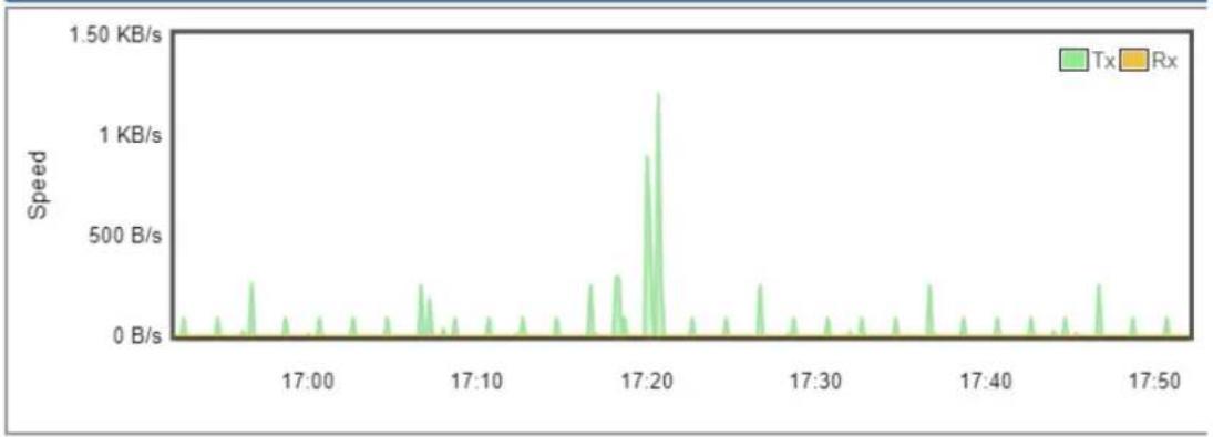
line
| Time | Speed | |--------|-----------| | 17:00 | ~0 B/s | | 17:10 | ~0 B/s | | 17:20 | ~1.50 KB/s| | 17:30 | ~0 B/s | | 17:40 | ~0 B/s | | 17:50 | ~0 B/s |5GHz

line
| Time | Speed | |--------|-----------| | 17:00 | ~0 B/s | | 17:10 | ~0 B/s | | 17:20 | ~1.2 KB/s | | 17:30 | ~0 B/s | | 17:40 | ~0 B/s | | 17:50 | ~0 B/s |Figure 4.9-6 Wi-Fi Statistics
4.9.6 Connection Status
This page shows the host names and MAC address of all the clients in your network as shown below.
| Client List | ||||
| No. | Name | MAC Address | Signal | Connected Time |
Figure 4.9-7 Connection Status
| Object | Description |
| Name | Display the host name of connected clients. |
| MAC Address | Display the MAC address of connected clients. |
| Signal | Display the connected signal of connected clients. |
| Connected Time | Display the connected time of connected clients. |
4.10 Power over Ethernet
(For IVR-300FP Only)
The PoE menu provides the following features for managing the system.

flowchart
graph TD
    A["PoE Configuration"] --> B["PoE Status"]
    B --> C["PoE Schedule"]
    C --> D["PoE Alive Check"]
Figure 4.10-1 PoE Menu
| Object | Description |
| PoE Configuration | Allows to centralize management of PoE power for PDs. |
| PoE Status | Displays the current PoE usage. |
| PoE Schedule | Allows centralizing management of PoE power for providing schedule. |
| PD Alive Check | Allows centralizing management of PoE power for checking PDs alive. |
4.10.1 PoE Configuration
This section allows the user to inspect and configure the current PoE configuration setting.
![PoE Configuration System PoE Admin Mode Enable Power Supply 51 V Power Limit Mode Consumption Power Allocation 0 / 120 W Port Description PoE Function Schedule Power Mode Priority Device Class Current Used [mA] Powered Used [W] All √ √ AT/AF √ 1 Enable None AT/AF High - - 0 0 2 Enable None AT/AF High - - 0 0 3 Enable None AT/AF High - - 0 0 4 Enable None AT/AF High - - 0 0 Total 0 0 Apply Settings Cancel Changes](/content/2026/05/1063066/images/63642da05eee9125f2f89db1b5d8440c10bde5dad2359a8f83534096501ac348.jpg)
Figure 4.10-2 PoE configuration
| Object | Description |
| System PoE Admin Mode | Allows user to enable or disable PoE function. It will cause all of PoE ports to supply or not to supply power. |
| PoE Function | There are three modes for PoE mode.■ Enable: enable PoE function..■ Disable: disable PoE function.■ Schedule: enable PoE function in schedule mode. |
| Schedule | Indicates the scheduled profile mode. Possible profiles are:■ Profile1■ Profile2■ Profile3■ Profile4 |
| Priority | The Priority represents PoE ports priority. There are three levels of power priority named Low, High and Critical.The priority is used in case the total power consumption is over the total power budget. In this case, the port with the lowest priority will be turned off, and power for the port of higher priority will be offered. |
| Device Class | Displays the class of the PD attached to the port, as established by the classification process. Class 0 is the default for PDs. The PD is powered based on PoE Class level if the system is working in Classification mode. The PD will return to Class 0 to 4 in accordance with the maximum power |
| Current Used [mA] | The Power Used shows how much current the PD currently is using. |
| Powered Used [W] | The Power Used shows how much power the PD currently is using. |
4.10.2 PoE Status
This section provides per port PoE status.
Port Power Consumption

line
| Port Number | AF PoE | AT PoE | | ----------- | ------ | ------ | | 01 | 0 W | 0 W | | 02 | 0 W | 0 W | | 03 | 0 W | 0 W | | 04 | 0 W | 0 W |Figure 4.10-3 Port Power Consumption
4.10.3 PoE Schedule
This page allows the user to define PoE schedule and scheduled power recycling.
Please press the Add New Rule button to start setting PoE Schedule function. You have to set PoE schedule to profile and then go back to PoE Port Configuration, and select "Schedule" mode from per port "PoE Mode" option to enable you to indicate which schedule profile could be applied to the PoE port.


line
| Day | PoE Schedule | PoE Reboot | |-------|--------------|------------| | Mon | | | | Sun | | | | Wed | | | | Thu | | | | Fri | | | | Sat | | |Figure 4.10-4 PoE schedule Configuration
| Object | Description |
| • Profile | Set the schedule profile mode. Possible profiles are:Profile1Profile2Profile3Profile4 |
| • Week Day | Allows user to set week day for defining PoE function by enabling it on the day. |
| • Start Hour | Allows user to set what hour PoE function does by enabling it. |
| • Start Min | Allows user to set what minute PoE function does by enabling it. |
| • End Hour | Allows user to set what hour PoE function does by disabling it. |
| • End Min | Allows user to set what minute PoE function does by disabling it. |
| • Reboot Enable | Allows user to enable or disable the whole PoE port reboot by PoE reboot schedule. Please note that if you want PoE schedule and PoE reboot schedule to work at the same time, please use this function, and don't useReboot Onlyfunction. This function offers administrator to reboot PoE device at an indicated time if administrator has this kind of requirement. |
| • Reboot Only | Allows user to reboot PoE function by PoE reboot schedule. Please note that if administrator enables this function, PoE schedule will not set time to profile. This function is just for PoE port to reset at an indicated time. |
| • Reboot Hour | Allows user to set what hour PoE reboots. This function is only for PoE reboot schedule. |
| • Reboot Min | Allows user to set what minute PoE reboots. This function is only for PoE reboot schedule. |
4.10.4 PD Alive Check
The VPN Router can be configured to monitor connected PD's status in real-time via ping action. Once the PD stops working and without response, the PoE Switch is going to restart PoE port power, and bring the PD back to work. It will greatly enhance the reliability and reduces administrator management burden.
PoE Alive Configuration
| Port | Mode | Remote PD IP Address | Interval Time(10~300s) | Retry Count(1~5) | Action | Reboot Time (30~180s) |
| All | ||||||
| 1 | Disable | 192.168.1.10 | 10 | 1 | None | 30 |
| 2 | Disable | 192.168.1.11 | 10 | 1 | None | 30 |
| 3 | Disable | 192.168.1.12 | 10 | 1 | None | 30 |
| 4 | Disable | 192.168.1.13 | 10 | 1 | None | 30 |
Figure 4.10-5 PoE Alive Configuration
| Object | Description |
| • Mode | Allows user to enable or disable per port PD Alive Check function.By default, all ports are disabled. |
| • Remote PD IP Address | This column allows user to set PoE device IP address for system making ping to the PoE device. Please note that the PD's IP address must be set to the same network segment with the PoE Switch. |
| • Interval Time (10~300s) | This column allows user to set how long system should issue a ping request to PD for detecting whether PD is alive or dead.Interval time range is from 10 seconds to 300 seconds. |
| • Retry Count (1~5) | This column allows user to set the number of times system retries ping to PD.For example, if we set count 2, it means that if system retries ping to the PD and the PD doesn't response continuously, the PoE port will be reset. |
| • Action | Allows user to set which action will be applied if the PD is without any response. The PoE Switch Series offers the following 3 actions:■ PD Reboot: It means system will reset the PoE port that is connected to the PD.■ PD Reboot & Alarm: It means system will reset the PoE port and issue an alarm message via Syslog.■ Alarm: It means system will issue an alarm message via Syslog. |
| • Reboot Time (30~180s) | This column allows user to set the PoE device rebooting time as there are so many kinds of PoE devices on the market and they have a different rebooting time.The PD Alive-check is not a defining standard, so the PoE device on themarket doesn’t report reboot done information to the PoE Switch. Thus, user has to make sure how long the PD will take to finish booting, and then set the time value to this column.System is going to check the PD again according to the reboot time. If you are not sure of the precise booting time, we suggest you set it longer. |
4.11 Maintenance
The Maintenance menu provides the following features for managing the system as shown below.

flowchart
graph TD
    A["Administrator"] --> B["Date & Time"]
    B --> C["Save/Restore Configuration"]
    C --> D["Firmware Upgrade"]
    D --> E["Reboot / Reset"]
    E --> F["Auto Reboot"]
    F --> G["Deiagnostics"]
Figure 4.11-1 Maintenance Menu
| Object | Description |
| Administrator | Allows changing the login username and password. |
| Date & Time | Allows setting Date & Time function. |
| Save/Restore Configuration | Export the VPN Security Gateway's configuration to local or USB sticker.Restore the VPN Security Gateway's configuration from local or USB sticker. |
| Firmware Upgrade | Upgrade the firmware from local or USB storage. |
| Reboot / Reset | Reboot or reset the system. |
| Auto Reboot | Allows setting auto-reboot schedule. |
| Diagnostics | Allows you to issue ICMP PING packets to troubleshoot IP. |
4.11.1 Administrator
To ensure the VPN Security Gateway's security is secure, you will be asked for your password when you access the VPN Security Gateway's Web-based utility. The default user name and password are "admin". This page will allow you to modify the user name and passwords as shown below.
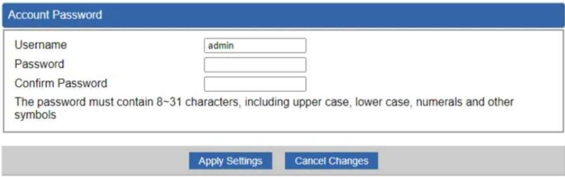
Figure 4.11-2 Account and Password Setting page
| Object | Description |
| Username | Input a new username. |
| Password | Input a new password. |
| Confirm Password | Input password again. |
4.11.2 Date and Time
This section assists you in setting the system time of the VPN Security Gateway. You are able to either select to set the time and date manually or automatically obtain the GMT time from Internet as shown below.

Figure 4.11-3 Date and Time setting page
| Object | Description |
| Current Time | Show the current time.User is able to set time and date manually. |
| Time Zone Select | Select the time zone of the country you are currently in. The VPN Security Gateway will set its time based on your selection. |
| NTP Client Update | Once this function is enabled, VPN Security Gateway will automatically update current time from NTP server. |
| NTP Server | User may use the default NTP sever or input NTP server manually. |
4.11.3 Saving/Restoring Configuration
This page shows the status of the configuration. You may save the setting file to either USB storage or PC and load the setting file from USB storage or PC as shown below.
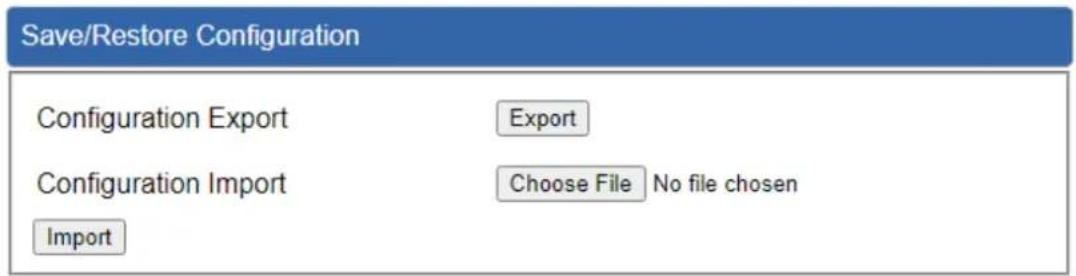
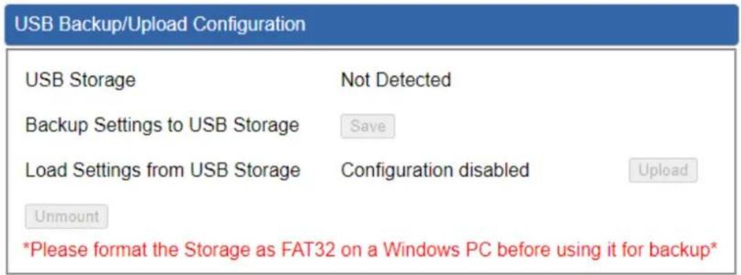
Figure 4.11-4 Saving/Restoring Configuration
■ Save Setting to PC
| Object | Description |
| Configuration Export | Press theExportbutton to save setting file to PC. |
| Configuration Import | Press theChoose Filebutton to select the setting file, and thenpress theImportbutton to upload setting file from PC. |
■ Save Setting to USB Storage
| Object | Description |
| USB Storage | The status of USB storage. |
| Backup Settings to USB Storage | Press the Save button to save setting file to USB storage. |
| Load Settings from USB Storage | Press the Unload button to upload setting file from USB storage. |
| Unmount | Before removing the USB storage from the VPN Security Gateway, please press the Umount button first. |
4.11.4 Firmware Upgrade
This page provides the firmware upgrade function as shown below.
Firmware Information
Firmware Version
v1.2102b220218
Last Upgrade Date
N/A
Firmware Upgrade
Select File
Choose File
No file chosen
Upgrade
USB Firmware Upgrade
USB Storage
Not Detected
Load Firmware from USB Storage
Not Found
Upload
Unmount
*Please format the Storage as FAT32 on a Windows PC before using it*
Figure 4.11-5 Firmware Upgrade page
| Object | Description |
| Choose File | Press the button to select the firmware. |
| Upgrade | Press the button to upgrade firmware to system. |
4.11.5 Reboot / Reset
This page enables the device to be rebooted from a remote location. Once the Reboot button is pressed, users have to re-log in the Web interface as shown below.

Figure 4.11-6 reboot/reset page
| Object | Description |
| Reboot | Press the button to reboot system. |
| Reset to Default | Press the button to restore all settings to factory default settings. |
| I'd like to keep the network profiles. | Check the box and then press the button to keep the current network profiles and reset all other configurations to factory defaults. |
4.11.6 Auto Reboot
This page enables the device to be Auto Rebooted on a Daily basis or based or Selected Week Day. The Web interface is shown below.
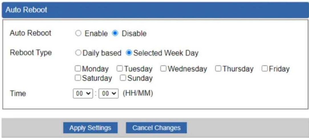
Figure 4.11-7 Auto Reboot Configuration
4.11.7 Diagnostics
The page allows you to issue ICMP PING packets to troubleshoot IP connectivity issues. After you press "Ping", ICMP packets are transmitted, and the sequence number and roundtrip time are displayed upon reception of a reply. The Page refreshes automatically until responses to all packets are received, or until a timeout occurs as shown below.

Figure 4.11-8 Diagnostics page
| Object | Description |
| Interface | Select an interface of the VPN Security Gateway |
| Target Host | The destination IP Address or domain. |
| Number of Packets | Set the number of packets that will be transmitted; the maximum is 100. |
| Ping | The time of ping. |

Be sure the target IP address is within the same network subnet of the VPN Security Gateway, or you have to set up the correct gateway IP address.
Appendix A: DDNS Application
Configuring PLANET DDNS steps:
Step 1: Visit DDNS provider's web site and register an account if you do not have one yet. For example, register an account at http://planetddns.com
Step 2: Enable DDNS option through accessing web page of the device.
Step 3: Input all DDNS settings.


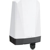
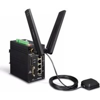
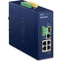

- User's Manual
- Industrial 5-Port 10/100/1000T VPN Security Gateway
- Copyright
- Disclaimer
- FCC Compliance Statement
- CE mark Warning
- Safety
- WEEE
- Trademarks
- Revision
- Table of Contents
- Chapter 1. Product Introduction....7
- Chapter 2. Hardware Introduction....23
- Chapter 3. Preparation ....39
- Planet Smart Discovery Utility....46
- Chapter 4. Web-based Management....48
- AP Control 117
- Wireless....128
- Power over Ethernet 134
- Maintenance....139
- Appendix A: DDNS Application 146
- Chapter 1. Product Introduction
- Package Contents
- Overview
- Powerful Industrial VPN Security Solution
- Flexible WAN interface Enables Extension of Network Deployment (For IVR-300FP)
- Intelligent SFP Diagnosis Mechanism (For IVR-300FP)
- Built-in Unique PoE Functions for Powered Devices Management (For IVR-300FP)
- PoE Usage Monitoring (For IVR-300FP)
- PoE Schedule (For IVR-300FP)
- Scheduled Power Recycling (For IVR-300FP)
- PD Alive Check (For IVR-300FP)
- PD Alive Check
- Wireless 11ax Brings Excellent Data Link Speed (For IVR-300W)
- Ideal VPN Security Gateway Solution for Factories and Transportations
- Centralized Remote Control of Managed APs
- Wi-Fi Deployments and Authentication with Simplified Management (for IVR-300 Series)
- Excellent Ability in Threat Defense
- Cybersecurity Network Solution to Minimize Security Risks
- Maximizing Work Efficiency with PLANET SD-WAN Gateway
- Cost-effective Solution for RS-485 to Ethernet Application (for IVR-300 Series.)
- Convenient and Reliable Redundant Power System
- Ideal VPN Security Gateway
- Features
- Hardware
- Power over Ethernet (for IVR-300FP)
- RF Interface Characteristics (for IVR-300W)
- Industrial Case and Installation
- IP Routing Feature
- Firewall Security
- VPN Features
- Networking
- Others
- ■ Power of Ethernet Specification for IVR-300FP
- ■ Wireless Specification for IVR-300W
- Chapter 2. Hardware Introduction
- Physical Descriptions
- Front View
- IVR-300 series Front Panel
- LED Definition:
- - Interface:
- 300/IVR-300W
- IVR-300FP
- Top View
- Wiring the Power Inputs
- Wiring the Fault Alarm Contact
- Dimensions
- Hardware Installation
- DIN-rail Mounting
- Wall Mount Plate Mounting
- Side Wall Mount Plate Mounting
- Wi-Fi Antenna Installation
- Chapter 3. Preparation
- Requirements
- Setting TCP/IP on your PC
- Windows 7/8
- Click "Change adapter settings".
- Right-click on the Local Area Connection and select Properties.
- Windows 10
- Planet Smart Discovery Utility
- Chapter 4. Web-based Management
- Introduction
- Logging in to the VPN Gateway
- Main Web Page
- Web Panel
- Main Menu
- System
- Wizard
- Step 1: Account Modification
- Step 2: LAN Interface
- Step 3: WAN Interface
- Mode 1 -- Static IP
- Mode 2 -- DHCP Client
- Step 4: Wireless Setting
- Step 5: Security Setting
- Step 6: Setup Completed
- Dashboard
- Status
- System Service
- Statistics
- Connection Status
- SFP Module Information
- High Availability
- RADIUS
- Captive Portal
- SNMP
- NMS
- Fault Alarm
- Digital Input / Output
- Modbus
- Remote Syslog
- Network
- Priority
- WAN
- WAN Advanced
- LAN
- Multi-Subnet
- VLAN
- UPnP
- Routing
- RIP
- OSPF
- IGMP
- IPv6
- DHCP
- DDNS
- PLANET DDNS
- PLANET Easy DDNS
- MAC Address Clone
- Security
- Firewall
- Firewall Protection
- DDoS
- System Security
- NATALGs
- MAC Filtering
- IP Filtering
- Web Filtering
- Port Forwarding
- QoS
- DMZ
- VPN
- IPSec
- IKE Setting
- Phase 1
- Phase 2
- IPsec Remote Server
- GRE
- PPTP
- L2TP
- SSL VPN
- Certificates
- VPN Connection
- SD WAN
- AP Control
- Simplified Cluster Management with 4 Steps
- Preference
- AP Search
- AP Management
- AP Group Management
- Action:
- ■ Create Group:
- SSID Profile
- Radio 2.4GHz Profile
- Radio 5GHz Profile
- Statistics AP Status
- Map It
- Upload Map
- Wireless
- 2.4GHz WiFi
- 5GHz WiFi
- MAC ACL
- Wi-Fi Advanced
- Wi-Fi Statistics
- Connection Status
- Power over Ethernet
- PoE Configuration
- PoE Status
- PoE Schedule
- PD Alive Check
- Maintenance
- Administrator
- Date and Time
- Saving/Restoring Configuration
- ■ Save Setting to PC
- ■ Save Setting to USB Storage
- Firmware Upgrade
- Firmware Information
- Firmware Upgrade
- USB Firmware Upgrade
- Reboot / Reset
- Auto Reboot
- Diagnostics
- Appendix A: DDNS Application
Brand : Planet
Model : IVR-300W
Category : Network router