
AKM 806 - Industrial electrical device Janitza - Free user manual and instructions
Find the device manual for free AKM 806 Janitza in PDF.


| Product Type | Power Quality Analyzer |
| Brand | Janitza |
| Model | AKM 806 |
| Dimensions (approx.) | 200 x 150 x 50 mm |
| Weight (approx.) | 0.5 kg |
| Power Supply | 100-240V AC, 50/60 Hz |
| Measurement Functions | Voltage, current, power, harmonics, power quality events |
| Communication Interfaces | Ethernet, USB, RS-485 (optional) |
| Display | Graphical LCD, 320x240 pixels |
| Data Logging | Internal memory, configurable logging interval |
| Accuracy Class | 0.5% for voltage and current |
| Compliance Standards | IEC 61000-4-30 Class A |
| Operating Temperature | -10°C to +55°C |
| Humidity | 5% to 95% non-condensing |
| Maintenance | Clean with dry cloth; do not use liquids |
| Safety Precautions | Follow local electrical codes; disconnect power before servicing |
| Spare Parts and Repairability | Contact Janitza customer service for spare parts or repairs |
| Manual | Free PDF manual available for download |
Frequently Asked Questions - AKM 806 Janitza
User questions about AKM 806 Janitza
0 question about this device. Answer the ones you know or ask your own.
Ask a new question about this device
Download the instructions for your Industrial electrical device in PDF format for free! Find your manual AKM 806 - Janitza and take your electronic device back in hand. On this page are published all the documents necessary for the use of your device. AKM 806 by Janitza.
USER MANUAL AKM 806 Janitza
English version: from page 43
for the busbar system BD2
- AKM 806 - AKM 96RME
- AKM 96RMPN - AKM 96PA
- AKM 96PAMID - AKM 96PQL
- AKM 103
Supplementary user manual

Abb. 6: AKM justieren (1,2)
Abb. 8: Offener AKM
natural_image
Technical line drawing of mechanical components including a bracket, screw base, and mounting bracket (no text or symbols)natural_image
Diagram showing two mechanical components with a tool and a separate branching structure, no text or symbols present.natural_image
Mechanical assembly diagram showing a bolted joint with bolts and a housing (no text or labels)natural_image
Mechanical assembly diagram showing bolted joint and mounting plate (no text or labels)for the busbar system BD2
- AKM 806 - AKM 96RME
- AKM 96RMPN - AKM 96PA
- AKM 96PAMID - AKM 96PQL
- AKM 103
Supplementary user manual

Busbar tap-off unit for the busbar system BD2
- AKM 806
- AKM 96RME
- AKM 96RMPN
- AKM 96PA
- AKM 96PAMID
- AKM 96PQL
- AKM 103
Supplementary user manual
Doc. no.: 2.551.030.0.j
Date: 04/2021
The German version is the original edition of the documentation
This document uses the masculine form according to grammar in a gender-neutral sense! It always addresses women, men and diverse. In order to keep texts easier to read, no distinctions are made. We ask for your understanding for these simplifications.
Subject to technical changes.
The contents of our documentation have been compiled with great care and reflect the current state of the information available to us. Nonetheless, we wish to point out that updates of this document are not always possible at the same time as technical refinements are implemented in our products. Please see our website under www.janitza.com for the current version.
TABLE OF CONTENTS
1. Information on the product and the user manual 48
1.1 Disclaimer 48
1.2 Copyright notice 48
1.3 Technical changes 48
1.4 About this user manual 48
1.5 Defective products/disposal 49
2. Safety 50
2.1 Display of warning notices and safety information 50
2.2 Hazard levels 50
2.3 Product safety 51
2.4 Dangers when handling the product 51
2.5 Electrically qualified personnel 52
2.6 Warranty in the event of damage 52
2.7 Dangers arising from the busbar tap-off unit 52
2.8 Safety information for handling current transformers and measurement devices with residual current measurement 53
2.9 Handling batteries/accumulators 54
3. Product description
3.1 Product description and application areas 56
3.2 Incoming goods inspection 57
3.3 Intended use 57
3.4 Performance characteristics 58
3.5 EU conformity declaration 58
3.6 Norms and standards 58
3.7 Types, variants and options 59
3.7.1 AKM 806 - Busbar tap-off unit with UMG 806 measurement device 59
3.7.2 AKM 96RME busbar tap-off unit with UMG 96RM-E measurement device....59
3. 7. 3 AKM 96RMPN - Busbar tap-off unit with UMG 96RM-PN measurement device ..... 60
3.7.4 AKM 96PA - Busbar tap-off unit with UMG 96-PA measurement device 60
3. 7. 5 AKM 96PAMID - Busbar tap-off unit with UMG 96-PA ^MID+ measurement device....61
3. 7. 6 AKM 96PQL - Busbar tap-off unit with UMG 96-PQ-L measurement device 61
3.7.7 AKM 103 - Busbar tap-off unit with UMG 103-CBM measurement device 62
3.8 Scope of delivery
3.9 Functions 63
3.9.1 Energy measurement 63
3.9.2 Measurement device protection .63
3.9.3 Current measurement 63
3.9.4 Residual current measurement (RCM) 63
3.9.5 Temperature measurement .63
3. 9. 6 Power input, cover disconnector and protection against contact 63
3.9.7 Power output 63
3.10 Communication 64
-
- 1 Ethernet interface (standard, exception AKM 103) 64
- 10.2 RS-485 interface (standard) 64
-
- 3 Digital input (option) 64
3.11 Device views
-
- 1 View - front and bottom 64
3.11.2 Dimensions 64
3.11.3 Interfaces 64
- 1 View - front and bottom 64
3. 12 Key system for type designation
-
13 Identification of the device (rating plate) 66
-
14 Installation and equipment options – schematic diagrams 68
4. Mounting
4.1 Busbar tap-off unit – System BD2 - 125 A, with cover disconnector 70
4.2 Busbar tap-off unit - System BD2 - 250/400/530 A, without cover disconnector 73
5. Installation
5.1 Circuit diagram / wiring variant 78
6. Technical data
6.1 Technical data of the busbar tap-off unit 80
6.2 Technical data of the installed measurement devices and components 82
7. Service and maintenance
7.1 Service 83
1. Information on the product and the user manual
1.1 Disclaimer
Compliance with the usage information for the products is a prerequisite for safe operation and attaining the stated performance characteristics and product features.
Janitza electronics GmbH assumes no liability for bodily injury, material damage or financial losses which result from disregard of the usage information.
Make sure that your usage information is readily available and legible!
This document is applicable as a supplement to the usage information provided by the manufacturer of the BD2 busbar system. In addition, all usage information of the installed devices and components in the busbar tap-off unit (AKM) is also applicable. Please pay attention to it!
1.2 Copyright notice
© 2020 - Janitza electronics GmbH - Lahnau. All rights reserved.
Any reproduction, processing, distribution or other use of this usage information, in whole or in part, is prohibited.
All trademarks and the rights arising from them are the property of the respective owners of these rights.
1.3 Technical changes
- Make sure that your product matches the user manual.
- This user manual applies to the busbar tap-off unit. Separate validities and distinctions are marked.
- First read and understand the documents associated with the product, including those relating to the installed devices, modules and components.
- Keep the documents associated with the product available for the entire service life and pass them on to any possible subsequent users.
- Find out about product revisions and the associated modifications of the documentation associated with your product at www.janitza.com.
1.4 About this user manual
If you have questions, suggestions or ideas for improvement of the user manual, please let us know via email at: info@janitza.com.
i INFORMATION
This user manual describes the tap-off unit for the BD2 busbar system and provides information on the operation of the product.
In addition to this user manual, please also note further usage information on the installed measurement devices and components, such as
- Installation instructions.
- Data sheets.
- Safety information.
- Usage information on the BD2 busbar system.
- Usage information on installed measurement devices and components.
- The online help for the GridVi® power grid monitoring software.
1.5 Defective products/disposal
Before sending defective products, devices, modules or components back to the manufacturer for testing:
- Contact the manufacturer's Support department.
- Send products, devices, modules or components complete with all accessories.
- When doing so, please bear the terms for transportation in mind.
i INFORMATION
Please return defective or damaged products, devices, modules or components to Janitza electronics GmbH in accordance with the shipping instructions for air or road freight (complete with accessories). Observe special regulations for devices with built-in batteries or rechargeable batteries!
Do not open or repair devices, modules and components on your own, otherwise the warranty will become void!
For the disposal of the product, device, components or modules, please observe national regulations! Dispose of individual parts, as applicable, depending on their composition and existing country-specific regulations, for example, as
- Electronic waste,
- Batteries and rechargeable batteries.
· Plastics. - Metals.
Engage a certified disposal company to handle scrapping as needed.
Information on service and maintenance of your devices and components can be found in chapter „Service and maintenance“ auf S. 83.
2. Safety
The chapter on Safety contains information which must be observed to ensure your personal safety and avoid material damage.
2.1 Display of warning notices and safety information
The warning notices shown below
- can be found in all documents concerning the use of your devices, modules and components.
- can be found on the devices, modules and components themselves.
· indicate potential risks and hazards.
· underscore aspects of the information provided that clarifies or simplifies procedures.

The additional symbol on the devices, modules and components themselves indicates an electrical hazard that could result in serious injury or death.

This general warning symbol draws attention to a possible risk of injury. Be certain to observe all of the information listed under this symbol in order to avoid possible injury or even death.

2.2 Hazard levels
Warning and safety information is marked by a warning symbol, and the hazard levels are shown as follows, depending on the degree of hazard:
DANGER
Warns of an imminent danger which, if not avoided, results in serious or fatal injury.
WARNING
Warns of a potentially hazardous situation which, if not avoided, could result in serious injury or death.
CAUTION
Warns of an immediately hazardous situation which, if not avoided, can result in minor or moderate injury.
ATTENTION
Warns of an immediately hazardous situation which, if not avoided, can result in material or environmental damage.
i INFORMATION
Indicates procedures in which there is no hazard of personal injury or material damage.
2.3 Product safety
The product reflects current engineering practice and accepted safety standards, but hazards can arise nonetheless.
Observe the safety regulations and warning notices. If notices are disregarded, this can lead to personal injury and/or damage to the product.
Every type of tampering with or use of this product,
· which goes beyond the mechanical, electrical or other operating limits can lead to personal injury and/or damage to the product.
- constitutes “misuse” and/or “negligence” under the product’s warranty and thus voids the warranty for any possible resulting damage.
Read and understand the associated usage information before assembling/installing, operating, maintaining and using the product.
Only operate the product when in perfect condition and in compliance with this supplementary user manual. Please also observe the usage information of the installed measurement devices and components!
Send defective products back to the manufacturer in compliance with the transport conditions. Retain the usage information of the busbar tap-off unit throughout the service life of the product and keep it available for reference.
When using the product, also observe the legal and safety regulations for your system that are applicable for the respective use case.
2.4 Dangers when handling the product
When operating electrical products, certain parts can inevitably conduct hazardous voltage. Consequently, severe bodily injury or material damage can occur if they are not handled properly.
Therefore, always observe the following when handling our products:
- Do not exceed the limit values specified in this user manual, the usage information on the measurement devices (modules, components) and on the rating plate! This must also be observed during testing and commissioning!
- Safety information and warnings in all usage information that belongs to the products!

WARNING
Risk of injury due to electrical voltage!
Severe bodily injury or death can result! Therefore please abide by the following:
- Switch off your installation before commencing work! Secure it against being switched on! Check to be sure it is de-energized! Ground and short circuit! Cover or block off adjacent live parts!
- During operation and troubleshooting (especially for DIN rail devices), check your system for dangerous voltages and switch these off if necessary!
- Wear protective clothing and protective equipment in accordance with applicable guidelines when working on electrical systems!
- Before making connections, ground devices, modules or components at the ground wire connection, if available!
- Do not touching bare or stripped leads that are energized! Equip stranded conductors with wire ferrules!
- Hazardous voltages can be present in all circuitry parts that are connected to the power supply.
- Protect your wiring, cables and devices (modules, components) with a suitable line circuit breaker/fuse!
- Never switch off, remove or tamper with safety devices!
- There can still be hazardous voltages present in the device or in the component even after it has been disconnected from the supply voltage (capacitor storage).
- Do not operate equipment with current transformer circuits when open.
- Only connect screw terminals with the same number of poles and design!
- Do not exceed the limit values specified in this user manual, in the usage information for the devices (modules, components) and on the rating plate! This must also be observed during testing and commissioning.
- Observe the safety and warning notices in the usage information associated with the devices modules and components!
2.5 Electrically qualified personnel
To avoid bodily injury and material damage, only electrically qualified personnel are permitted to work on the devices, components, assemblies, systems and current circuits who have knowledge of:
- the national and international accident prevention regulations,
· safety technology standards,
· installation, commissioning, operation, disconnection, grounding and marking of electrical equipment, - the requirements concerning personal protective equipment.
Electrically qualified persons within the scope of the technical safety information of all usage information associated with the device and its components are persons who can furnish proof of qualification as an electrically skilled person.

WARNING
Warning against unauthorized manipulation or improper use of the devices, modules and components!
Opening, dismantling or unauthorized manipulation of the device (modules components) which goes beyond the mechanical, electrical or other operating limits indicated can lead to material damage or injury, up to and including death.
- Only electrically qualified personnel are permitted to work on the devices, components, assemblies, systems and current circuits.
· Always use your device (module, component) as described in the associated usage information. - If there is discernible damage, send the device (module, component) back to the manufacturer!
2.6 Warranty in the event of damage
Any unauthorized manipulation of the product (devices, modules, components) constitutes "misuse" and/or "negligence" under the product's warranty and thus voids the warranty for any possible resulting damage. In this regard, please take note of chap. „3.3 Intended use“ auf Seite 57.
2.7 Dangers arising from the busbar tap-off unit

DANGER
Life-threatening danger or risk of injury due to dangerous voltages!
- Before starting work, disconnect your system and the busbar tap-off unit from the power supply, secure against reconnection, verify that the system is voltage-free, ground and short-circuit, cover or block off adjacent live parts.
- Only qualified electricians and personnel qualified in electrical engineering may perform the work described below [IEC 61439-1; EN 50110-1].
· Comply with country-specific safety regulations and regulations for working near live parts [EN 50110-1].
- Observe additional warnings on the device and its components.
2.8 Safety information for handling current transformers and measurement devices with residual current measurement
The following applies to the current transformers and measurement devices with residual current measurement used in the busbar tap-off unit:

WARNING
Risk of injury due to large currents and high electrical voltage on the current transformers! Current transformers operated while open on the secondary side (high voltage peaks pose a hazard when touched) can result in severe bodily injury or death.
- Avoid operating the current transformers while open; short circuit the unloaded transformers!
- Before interrupting the current supply, short circuit the secondary connections of the current transformers. Switch any test switches that automatically short circuit the secondary lines of the current transformers to the "Test" status (Check the test switch/short circuiting connection beforehand)!
· Only use current transformers with basic insulation to IEC 61010-1:2010!
- Caution, even current transformers rated as safe for open operation can pose a hazard when touched during operation while open!
- Make sure that screw terminals for the current transformer connection on the device are adequately tightened!
· Comply with the information and provisions in the documentation of your current transformers!

WARNING
Risk of injury or damage to the meter due to improper use!
Meters with residual current measurement can trigger warning pulses if limit values are exceeded, and these are used exclusively for monitoring residual currents or failure monitoring. Use of the warning pulses as a stand-alone protective device against electrical shock can lead to injury and even death!
- Do not use devices with residual current measurement as a stand-alone protective device. Employ suitable protective devices for your system!

CAUTION
Risk of injury or damage to the meter/your system due to short circuit!
Inadequate insulation of the operating equipment at the residual current measuring input with respect to the supply circuits can cause voltages at the measuring input which represent a hazard when touched or damage to your device or system.
- Ensure reinforced or double insulation with respect to the supply circuits!
Ensure galvanic isolation of the residual current measuring inputs from each other!

WARNING
Disregard of the connection conditions of the transformers to Janitza measurement devices or their components can lead to injuries or even death or to material damage!
- Do not use the outputs of the Janitza measurement devices or their components for switching protective devices or protective relays! Do not use "Transformers for protection purposes"!
- For Janitza measurement devices and their components use only “Transformers for measurement purposes” which are suitable for the energy monitoring of your system.
- Observe the information, regulations and limit values in the usage information on “Transformers for measuring purposes”, specifically during testing and commissioning of the Janitza measurement device, the Janitza component and your system.
2.9 Handling batteries/accumulators
The following applies to the measurement devices with batteries used in the busbar tap-off unit:

CAUTION
Risk of injury due to fire or burns!
The battery used in the device or its components can cause fire or burns if used improperly.
- Only replace the battery with the same type or types recommended by Janitza!
- Observe the polarity when installing the battery!
- Remove batteries only with non-conductive tools (e.g. plastic tweezers)!
· Do not recharge, disassemble, burn or heat batteries above 100 °C (212 °F)!
· Do not dispose of batteries with household waste! Follow the disposal instructions in the respective device documentation!
- Keep batteries away from children and animals!
- In case of damage, return devices with a soldered battery to the manufacturer, observing proper transport conditions!
3. Product description
3.1 Product description and application areas
The busbar tap-off unit (AKM tap-off unit with measurement technology) is used for the analysis of energy efficiency in busbar trunking systems of the type BD2. The BD2 busbar trunking system is used for power transmission and distribution with communication capability in office buildings and industrial plants.
This supplementary user manual for the busbar tap-off unit assumes that a BD2 busbar system is already installed. Variants for other busbar systems must be evaluated in each individual case. The implementation depends on technical and economic boundary conditions.
The busbar tap-off unit for the BD2 busbar trunking system offers maximum safety through tested low-voltage switchgear combinations according to IEC 60439-1 / -21.
The high short-circuit resistance and low fire load due to the sheet steel housing increase safety for people and buildings.
In contrast to conventional cable installation, where electricity can only be tapped at fixed points, the ready-dimensioned busbar tap-off units can be used flexibly and varied on the busbar trunking systems (BD2). The installation is carried out without any intervention in the connected consumer (e.g. machine) and the associated loss of warranty.
The AKM busbar tap-off unit
- is a ready dimensioned system for the connection and energy monitoring of an electrical consumer (e.g. a machine).
· performs a detailed energy efficiency analysis at the machine level.
· is a ready dimensioned system which monitors electrical parameters, such as currents, voltages, power, power quality, etc. via the built-in measurement device and the associated network analysis - can monitor the enclosure temperature and indirectly the entire busbar system.
Various options and design variants of the bus-bar tap-off unit allow adaptation to the respective measurement task. This includes, for example, an extended RCM measurement and the recording of additional consumption values via pulse inputs.
i INFORMATION
Please note!
The size of the busbar tap-off unit depends on the variants (see „Technical data“ auf S. 80)!
The feed of the 125 A version of the busbar tap-off unit is equipped with a cover disconnector, which disconnects the tap-off unit from the live busbar system when the cover is opened. This allows shockproof working on the installed tap-off unit.
With all other versions of the busbar tap-off unit, there is no disconnection when the cover is opened! In this case, a finger-safe design provides protection against contact.
3.2 Incoming goods inspection
Safe and trouble-free operation of this product and its components presupposes proper transport, proper storage, set-up and assembly as well as operation and maintenance in addition to compliance with the safety information and warning notices.
Exercise due caution when unpacking and packing the device, do not use force and only use suitable tools.
Before mounting and installing the product, please check
- Its flawless mechanical condition by visual inspection.
· The scope of delivery for completeness.
If it can be assumed that safe operation of the product is no longer possible:
- Disconnect the product from operation immediately!
- Secure the product against being switched on again!
It can be assumed that safe operation is no longer possible, for example, if the device:
- Has visible damage.
- No longer functions despite an intact power supply.
- Was subjected to extended periods of unfavorable conditions (e.g. storage outside of the permissible climate thresholds without adjustment to the room climate, condensation, etc.) or transport stress (e.g. falling from an elevated position, even without visible external damage, etc.).

CAUTION
Malfunction, damage or risk of injury due to improper connection of the device and its components.
Improperly connected devices can deliver incorrect measured values, damage the device or pose a risk of injury to persons.
Observe all
- usage information on the device and its components!
- Switch off your installation before commencing work! Secure it against being switched on! Check to be sure it is de-energized! Ground and short circuit! Cover or block off adjacent live parts!
3.3 Intended use
The busbar tap-off unit together with the BD2 busbar trunking system is:
- Intended for installation in office buildings and industrial plants.
- Plannable, for efficient and flexible energy distribution within building complexes.
- Not intended for installation in vehicles! Use of the product in non-stationary equipment constitutes an exceptional environmental condition and is only permissible by special agreement.
- Not intended for installation in environments with harmful oils, acids, gases, vapors, dusts, radiation, etc.
- Not to be exposed to direct sunlight and inadmissible climatic conditions, such as rain.
Safe and trouble-free operation of the product requires proper transport, storage, assembly, installation, operation and maintenance.
3.4 Performance characteristics
For the performance characteristics of the BD2 busbar system, your busbar tap-off unit and the components installed in it, please refer to the respective usage information.
Included in the scope of delivery for each tap-off unit is a supplementary user manual for mounting the device and for plugging it onto the busbar system.
Features of the BD2 busbar tap-off unit:
- Sheet steel housing, hot-dip galvanized and powder-coated, color light gray, RAL 7035 (special colors on request).
- Assembly and disassembly of the tap-off units is only possible with the cover open.
An anti-twist feature prevents incorrect placement.
- The insertion of power cables is possible from two directions. (Use cable fittings with strain relief. Cable fittings not included in the scope of delivery.)
- Energy tapping via silver-plated contacts.
For further characteristics of the busbar tap-off unit with components and the BD2 busbar system, please refer to the manufacturer's usage information for your version. For further information on the installed components, please contact Janitza electronics GmbH.
3.5 EU conformity declaration
Please see the EU declaration of conformity posted at www.janitza.com for the laws, standards and directives applied by Janitza electronics GmbH for the devices. The CE conformity marking requirements for the device arise from the EU conformity declaration and the laws, standards and directives mentioned therein.
3.6 Norms and standards
The busbar tap-off unit was designed and manufactured according to the following norms and standards:
- CE conformity according to 2014/30/EU (Electromagnetic Compatibility Directive) and 2014/35/EU (Low Voltage Directive).
· DIN EN 61439 (standard for low-voltage switch-gear and controlgear assemblies).
- Regulation (EC) No. 1907/2006 (REACH Regulation).
· EU Directive 2011/65/EU (RoHS Directive).
3.7 Types, variants and options
3.7.1 AKM 806 - Busbar tap-off unit with UMG 806 measurement device
| AKM 806 - 125 AKM | 806 - 250 AKM 806 - 400 | AKM 806 - 530 | ||
| Maximum output current 125 A 250 A 400 A 530 A | ||||
| Current transformer 150 A / 5 A CI.1 250 A / 5 A CI.1 400 A / 5 A CI.1 600 A / 5 A CI.1 | ||||
| Current measurement 3P, 3P+N | √ √ √ | √ | ||
| Ethernet interface (RJ45 socket) | √ √ √ | √ | ||
| RS-485 interface(1x socket, 1x plug) | √ √ √ | √ | ||
| Circuit breaker(measurement device fuse) | √ √ √ | √ | ||
| Temperature measurement(PT 100 sensor) | √ √ √ | √ | ||
| RCM measurementType A | √ √ √ | √ | ||
| RCM measurement1)Type A/B/B+ | -RCMplus - optional | -RCMplus - optional | -RCMplus - optional | -RCMplus - optional |
| Current transformer forRCM measurement | CT-AC RCM 35N | CT-AC RCM 80N | CT-AC RCM 110N | CT-AC RCM 140N |
1) ... For an RCM measurement according to type A/B/B+, the AKM also requires the RCM 202-AB measurement device.
3.7.2 AKM 96RME busbar tap-off unit with UMG 96RM-E measurement device
| AKM RME - 125 | AKM RME - 250 | AKM RME - 400 | AKM RME - 530 | |
| Maximum output current 125 A 250 A 400 A 530 A | ||||
| Current transformer 150 A / 5 A CI.1 250 A / 5 A CI.1 400 | A / 5 A CI.1 600 A / 5 A CI.1 | |||
| Current measurement 3P, 3P+N | √ √ √ | √ | ||
| Ethernet interface (RJ45 socket) | √ √ √ | √ | ||
| RS-485 interface(1x socket, 1x plug) | √ √ √ | √ | ||
| Circuit breaker(measurement device fuse) | √ √ √ | √ | ||
| Temperature measurement(PT 100 sensor) | √ √ √ | √ | ||
| RCM measurementType A | √ √ √ | √ | ||
| RCM measurement1)Type A/B/B+ | -RCMplus - optional | -RCMplus - optional | -RCMplus - optional | -RCMplus - optional |
| Current transformer forRCM measurement | CT-AC RCM 35N | CT-AC RCM 80N | CT-AC RCM 110N | CT-AC RCM 140N |
| Digital input with24 V supply2) | -DI - optional | -DI - optional | -DI - optional | -DI - optional |
1) ... For an RCM measurement according to type A/B/B+, the AKM also requires the RCM 202-AB measurement device.
2) ... To record external pulses, the AKM requires a power supply unit (24 V) to supply the pulse generator.
3.7.3 AKM 96RMPN - Busbar tap-off unit with UMG 96RM-PN measurement device
| AKM 96RMPN - 125 A | AKM 96RMPN - 250 AKM | 96RMPN - 400 AKM 96 | RMPN - 530 | |
| Maximum output current 125 A 250 A 400 A 530 A | ||||
| Current transformer 150 A / 5 A K | .1 250 A / 5 A KI.1 400 | A / 5 A KI.1 600 A / 5 A KI.1 | ||
| Current measurement 3P, 3P+N | √ √ √ | √ | ||
| Ethernet interface/PROFINET connection (RJ45 socket) | √ √ √ | √ | ||
| RS-485 interface(1x socket, 1x plug) | √ √ √ | √ | ||
| Circuit breaker(measurement device fuse) | √ √ √ | √ | ||
| Temperature measurement(PT 100 sensor) | √ √ √ | √ | ||
| RCM measurementType A | √ √ √ | √ | ||
| RCM measurement1)Type A/B/B+ | -RCMplus - optional | -RCMplus - optional | -RCMplus - optional | -RCMplus - optional |
| Current transformer forRCM measurement | CT-AC RCM 35N CT | -AC RCM 80N CT | -AC RCM 110N CT | -AC RCM 140N |
| Digital input with24 V supply2) | -DI - optional | -DI - optional | -DI - optional | -DI - optional |
1) ... For an RCM measurement according to type A/B/B+, the AKM also requires the RCM 202-AB measurement device.
2) ... To record external pulses, the AKM requires a power supply unit (24 V) to supply the pulse generator.
3.7.4 AKM 96PA - Busbar tap-off unit with UMG 96-PA measurement device
| AKM 96PA - 125 | AKM 96PA - 250 | AKM 96PA - 400 | AKM 96PA - 530 | |
| Maximum output current 125 A 250 A 400 A 530 A | ||||
| Current transformer | 150 A / 5 A CI.1 | 250 A / 5 A CI.1 | 400 A / 5 A CI.1 | 600 A / 5 A CI.1 |
| Current measurement 3P, 3P+N | √ √ √ | √ | ||
| Ethernet interface (RJ45 socket) | √ √ √ | √ | ||
| RS-485 interface(1x socket, 1x plug) | √ √ √ | √ | ||
| Circuit breaker(measurement device fuse) | √ √ √ | √ | ||
| Temperature measurement(PT 100 sensor) | √ √ √ | √ | ||
| RCM measurementType A | √ √ √ | √ | ||
| RCM measurement1)Type A/B/B+ | -RCMplus - optional | -RCMplus - optional | -RCMplus - optional | -RCMplus - optional |
| Current transformer forRCM measurement | CT-AC RCM 35N CT | -AC RCM 80N CT | -AC RCM 110N CT | -AC RCM 140N |
| Digital input with24 V supply2) | -DI - optional | -DI - optional | -DI - optional | -DI - optional |
1) ... For an RCM measurement according to type A/B/B+, the AKM also requires the RCM 202-AB measurement device.
2) ... To record external pulses, the AKM requires a power supply unit (24 V) to supply the pulse generator.
3.7.5 AKM 96PAMID - Busbar tap-off unit with UMG 96-PA ^MID+ measurement device
| AKM 96PAMID - 125 A | AKM 96PAMID - 250 AKM | 96PAMID - 400 AKM | 96PAMID - 530 | |
| Maximum output current 125 A 250 A 400 A 530 A | ||||
| Current transformer 150 A / 5 A K | .1 250 A / 5 A KI.1 400 | A / 5 A KI.1 600 A / 5 A KI.1 | ||
| Current measurement 3P, 3P+N | ✓ ✓ ✓ | ✓ | ||
| Ethernet interface (RJ45 socket) | ✓ ✓ ✓ | ✓ | ||
| RS-485 interface(1x socket, 1x plug) | ✓ ✓ ✓ | ✓ | ||
| Circuit breaker(measurement device fuse) | ✓ ✓ ✓ | ✓ | ||
| Temperature measurement(PT 100 sensor) | ✓ ✓ ✓ | ✓ | ||
| RCM measurementType A | ✓ ✓ ✓ | ✓ | ||
| RCM measurement1)Type A/B/B+ | -RCMplus - optional | -RCMplus - optional | -RCMplus - optional | -RCMplus - optional |
| Current transformer forRCM measurement | CT-AC RCM 35N | CT-AC RCM 80N | CT-AC RCM 110N | CT-AC RCM 140N |
| Digital input with24 V supply2) | -DI - optional | -DI - optional | -DI - optional | -DI - optional |
| Display of the active energymeasured values relevant tocalibration law | ✓ ✓ ✓ | ✓ | ||
| Tamper-proof meter reading | ✓ ✓ ✓ | ✓ | ||
1) ... For an RCM measurement according to type A/B/B+, the AKM also requires the RCM 202-AB measurement device.
2) ... To record external pulses, the AKM requires a power supply unit (24 V) to supply the pulse generator.
3.7.6 AKM 96PQL - Busbar tap-off unit with UMG 96-PQ-L measurement device
| AKM 96PQL - 125 | AKM 96PQL - 250 | AKM 96PQL - 400 | AKM 96PQL - 530 | |
| Maximum output current 125 A 250 A 400 A 530 A | ||||
| Current transformer 150 A / 5 A K.1 250 A / 5 A KI.1 400 A / 5 A KI.1 600 A / 5 A KI.1 | ||||
| Current measurement 3P, 3P+N | √ √ √ | √ | ||
| Ethernet interface (RJ45 socket) | √ √ √ | √ | ||
| RS-485 interface(1x socket, 1x plug) | √ √ √ | √ | ||
| Circuit breaker(measurement device fuse) | √ √ √ | √ | ||
| Temperature measurement(PT 100 sensor) | √ √ √ | √ | ||
| RCM measurementType A | √ √ √ | √ | ||
| RCM measurement1)Type A/B/B+ | -RCMplus - optional | -RCMplus - optional | -RCMplus - optional | -RCMplus - optional |
| Current transformer forRCM measurement | CT-AC RCM 35N | CT-AC RCM 80N | CT-AC RCM 110N | CT-AC RCM 140N |
| Digital input with24 V supply2) | -DI - optional | -DI - optional | -DI - optional | -DI - optional |
1) ... For an RCM measurement according to type A/B/B+, the AKM also requires the RCM 202-AB measurement device.
2) ... To record external pulses, the AKM requires a power supply unit (24 V) to supply the pulse generator.
3.7.7 AKM 103 - Busbar tap-off unit with UMG 103-CBM measurement device
| AKM 103 - 125 AKM | 103 - 250 AKM 103 - 400 | AKM 103 - 530 | ||
| Maximum output current 125 A 250 A 400 A 530 A | ||||
| Current transformer 150 A / 5 A KI.1 250 A / 5 A KI.1 400 A / 5 A KI.1 600 A / 5 A KI.1 | ||||
| Current measurement 3P | √ √ √ | √ | ||
| RS-485 interface(1x socket, 1x plug) | √ √ √ | √ | ||
| Circuit breaker(measurement device fuse) | √ √ √ | √ | ||
3.8 Scope of delivery
This supplementary user manual for the busbar tap-off unit assumes that a BD2 busbar system is already installed.
| Item | Scope of delivery (designation) |
| 1 | BD2 busbar tap-off unit,AKM XXX --> unit type see type designation |
| 2 | Dummy plug to close the unused outgoing power feeder |
Not included in delivery:
- Screw connections for the load output.
- Cable connectors for the network connection (Ethernet and RS-485).
- Cable connectors for the digital input (with corresponding option).
i INFORMATION
- All supplied options and design variants of your busbar tap-off unit are described on the delivery note.
- See separate document for parts list!
i INFORMATION
Please note!
The size of the busbar tap-off unit depends on the variants (see „Technical data“ auf S. 80)!
The feed of the 125 A version of the busbar tap-off unit is equipped with a cover disconnector, which disconnects the tap-off unit from the live busbar system when the cover is opened. This allows shockproof working on the installed tap-off unit.
With all other versions of the busbar tap-off unit, there is no disconnection when the cover is opened! In this case, a finger-safe design of the busbar tap-off unit provides protection against contact.
3.9 Functions
Depending on the version of the AKM busbar tap-off unit and the installed measurement device (UMG 806, UMG 96RM-E, UMG 96RM-PN, UMG 96-PA, UMG 96-PA ^MID+ , UMG 96-PQ-L, UMG 103-CBM), the following functions can be realized:
3.9.1 Energy measurement
For the measurement of your relevant electrical parameters, please refer to the usage information for the following Janitza measurement devices:
The measurement device is protected by a circuit breaker built into the AKM.
3.9.3 Current measurement
The AKM measures all phase currents and the neutral conductor current. Depending on the variant of the AKM, the following current transformers are installed for this purpose:
· AKM xxx-125 --> 150 A/5 A, Cl.1
· AKM xxx-250 --> 250 A/5 A, Cl.1
· AKM xxx-400 --> 400 A/5 A, Cl.1
· AKM xxx-530 --> 600 A/5 A, Cl.1
Deviating from this, devices of the AKM 96PA-MID type are equipped with clearing transformers KI. 0.5.
3.9.4 Residual current measurement (RCM)
The following transformers are used to measure residual currents of type A at the residual current input of the installed measurement device:
· AKM xxx-125 --> CT-AC RCM 35N
· AKM xxx-250 --> CT-AC RCM 80N
· AKM xxx-400 --> CT-AC RCM 110N
· AKM xxx-530 --> CT-AC RCM 140N
i INFORMATION
For the AKMs 125/250/400/530 A there is the option for enhanced residual current measurement (RCMplus) according to Type A/B/B+ by means of built-in RCM 202-AB residual current measurement devices. This does not apply to the AKM 103!
3.9.5 Temperature measurement
The interior temperature of the busbar tap-off unit is measured by a PT100 temperature sensor. The PT100 temperature sensor is installed close to the NH fuses where the greatest heating of the AKM is expected.
3.9.6 Power input, cover disconnector and protection against contact
The BD2 busbar trunking system serves as the contact device for the busbar tap-off unit, thereby enabling power transmission and distribution to all areas of industry.
The 125 A version of the AKM has a cover disconnector to sever the connection to the power supply. This enables shockproof working when the enclosure is open, despite the voltage applied in the busbar distributors.
All other AKM variants (250 A, 400 A, 350 A) are standard enclosures from the manufacturer and have a shockproof construction for user safety.
3.9.7 Power output
The consumer (e.g. machine) is connected to the AKM via 5 terminals (L1, L2, L3, N and PE). 3 NH fuses protect phases L1 to L3. The maximum permissible fuse protection can be found on the rating plate.
The power output on the AKM can vary, see chapter „Installation and equipment options – schematic diagrams“ auf S. 68.
3.10 Communication
The busbar tap-off unit with AKM measurement technology has the following listed data interfaces for communication with other instances.

INFORMATION
- The arrangement of the data interfaces on the AKM can be found in chapter „Interfaces“ auf S. 64.
- Detailed information about communication and data interfaces can be found in the usage information of the installed measurement devices.
3.10.1 Ethernet interface (standard, exception AKM 103)
The Modbus TCP/IP communication takes place via an industry standard RJ45 interface, which leads from the measurement device to an RJ45 connection socket on the AKM.
3.10.2 RS-485 interface (standard)
Mode RTU communication takes place via 2 RS-485 interfaces leading from the measurement device connections to a socket and a plug on the AKM. This makes it easy to implement master-slave topologies.
3.10.3 Digital input (option)
The digital input of the measurement device is also provided as a socket on the AKM. The optional digital input (S0 input) is used, for example, to record the consumption of compressed air or coolant.
The measured values of the equipment (consumer) connected to the digital input are stored in the installed measurement device and can be evaluated and analyzed, for example, using the GridVis® software.
The AKM with the "digital input" option includes a 24 V power supply unit to supply external devices.
The following types have the "digital input" option:
AKM 96RME
AKM 96RMPN
AKM 96PA
AKM 96PAMID
AKM 96PQL
3.11 Device views
3.11.1 View - front and bottom

Fig.: Example AKM 96RME-125
(device views depending on the device type)
3.11.3 Dimensions
| Type | Width * (W in mm) | Height * (H in mm) | Depth * (D in mm) |
| AKM xxx-125 | 530 305 | 105 | |
| AKM xxx-250 | 662 406 | 202 | |
| AKM xxx-400 | 862 406 | 202 | |
| AKM xxx-530 | 862 406 | 352 |
* Specifications may vary slightly.
3.11.2 Interfaces
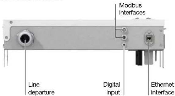
Fig.: Example AKM 96RME-125
(Interfaces depend on the device type and variant)
3.12 Key system for type designation
Janitza type designation:
AKM xxx-yyy-zzz-ooo
| ooo = Option (if available) | |
| DI Digital input | |
| RCM+ | RCM A/B/B+ (residual current measurement) |
| zzz = Busbar system | |
| (without) Siemens BD2 | |
| LD Siemens LD | |
| yyy = Maximum output current | |
| 125 125 A | |
| 250 250 A | |
| 400 400 A | |
| 530 530 A | |
| xxx= Measuring device type | |
| 806 UMG 806 | |
| 96RME UMG 96RM-E | |
| 96RMPN UMG 96RM-PN | |
| 96PA UMG 96-PA | |
| 96PAMID UMG 96-PAMID+ | |
| 96PQL UMG 96-PQ-L | |
| 103 UMG 103-CBM | |
AKM product family
Tap-off unit with measurement technology
3.13 Identification of the device (rating plate)

| Item Designation Description | ||
| 1 | Designation of origin Country of origin of the manufacturer. | |
| 2 | Postal address Postal address of the manufacturer. | |
| 3 | MAC address | Clear identification of the measurement device installed in the AKM for use in a computer network |
| 4 | Operational data Supply voltage, frequency, maximum current, overvoltage category | |
| 5 | Part number Manufacturer's part number | |
| 6 | Data matrix code Content: coded part number and type designation | |
| 7 | Manufacturer's logo Logo of the device manufacturer | |
| 8 | Device type AKM type | |
| 9 | Month/year of manufacture, hardware index | Date of device manufacture and hardware version of the device |
| 10 | CE conformity marking | See chapter „EU conformity declaration“ and „Norms and standards“ auf S. 58 |
| 11 | Serial number Number for identification of the device | |
| 12 | Applicable standard for the busbar tap-off unit | Standard for low voltage switchgear and controlgear assemblies |
| 13 | Web address Internet address of the manufacturer. | |
Tab: Device identification, rating plate
3.14 Installation and equipment options - schematic diagrams
When changing from variant 1 to variant 2, the measurement device can be pulled out of the holder, rotated by 180^ and reinserted.
i INFORMATION
The schematic representations of the installations show examples! The actual installation/equipment depends on the busbar tap-off unit variant selected.
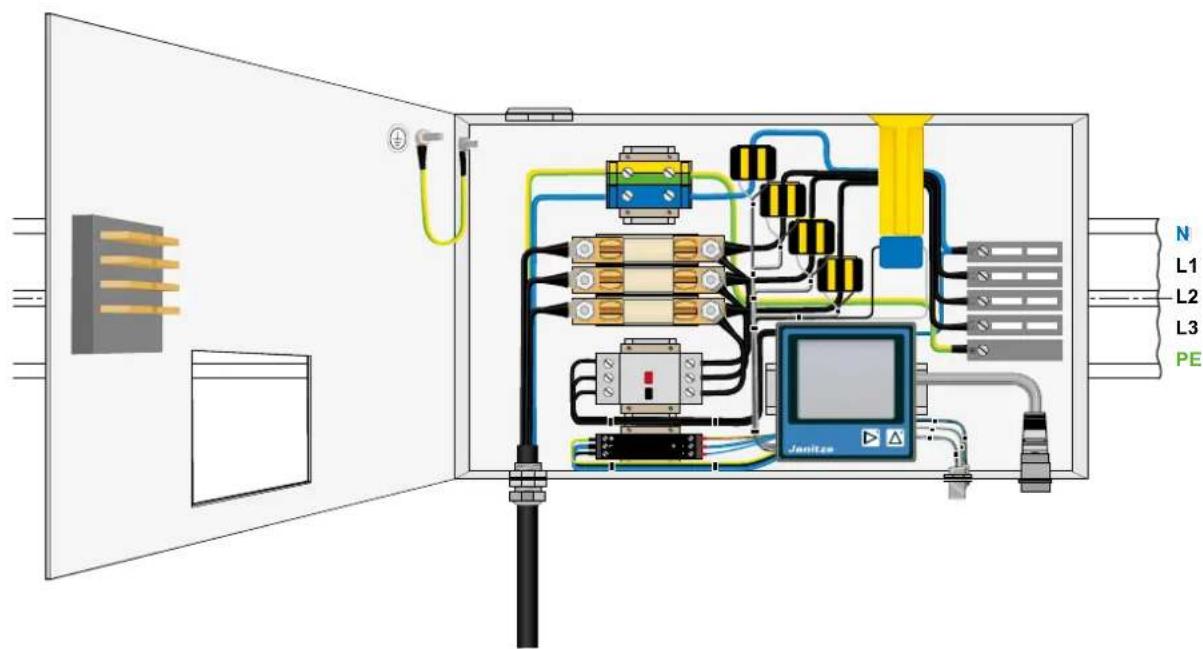
Fig.: Variant 1 (AKM 96RME-125) with PE connection "below": The enclosure is mounted in the as-delivered condition.
Fig.: Variant 2 (AKM 96RME-125) with PE connection "above":
The enclosure must turned 180° during mounting. The measurement device must be pulled out of its holder, rotated by 180° and reinserted. The blind plug must be removed and placed in the opposite opening.

| Item Designation Description | ||
| 1 | Busbar element Busbar element of the | BD2 system from Siemens |
| 2 | Ethernet interfaces See chapter „Interfaces“ auf S. 64. | |
| 3 | RS-485 interfaces See chapter „Interfaces“ auf S. 64. | |
| 4 | Janitza measurement device | Meters: UMG 96RM-E, UMG 96-PA or UMG 806 (for data, see user manual of the measurement device) |
| 5 | Motor circuit breaker Motor circuit breaker (for specification see chapter "Technical data") | |
| 6 | Power supply unit See chapter „Technical data“ auf S. 80. | |
| 7 | Door cutout | |
| 8 | Cover disconnector contacts Only available for the 125 A version of the busbar tap-off unit | |
| 9 | Protective earth/protective conductor | |
| 10 | Cable with screw connection Power output to the equipment | |
| 11 | Fuse (fuse base) 3x NH fuses (see chapter "Technical data") | |
| 12 | Through terminal (blue)Ground terminal (green/yellow) | |
| 13 | Current transformer 4x (depending on option) | |
| 14 | Residual current transformer 1x (option) | |
| 15 | Cover disconnector socket Only available for the 125 A version of the busbar tap-off unit | |
| 16 | BD2 busbar tap-off unit AKM 96RME-125 (top orientation, with right hand door hinge) | |
Tab: Busbar tap-off unit – installed components
4. Mounting
DANGER
Life-threatening danger or risk of injury due to dangerous voltages!
- Before starting work, disconnect your system and the busbar tap-off unit from the power supply, secure against reconnection, verify that the system is voltage-free, ground and short-circuit, cover or block off adjacent live parts.
· Only qualified electricians and personnel qualified in electrical engineering may perform the work described below [IEC 61439-1; EN 50110-1]. - Comply with country-specific safety regulations and regulations for working near live parts [EN 50110-1].
- Observe additional warnings on the device and its components.
4.1 Busbar tap-off unit – System BD2 - 125 A, with cover disconnector
i INFORMATION
The following steps show the installation of the busbar tap-off unit (system BD2 - 125 A variant, with cover disconnector), regardless of the equipment / installation. Please note, as already described under „Installation and equipment options – schematic diagrams“ auf S. 68, that the equipment of your busbar tap-off unit and thus the information on the mounting of components and cabling may differ from the following figures!
- Use a hexagon socket wrench or other suitable tool to open the AKM busbar tap-off unit.

Fig. 1: Open AKM.
- The 125 A version of the AKM has a cover disconnector, which separates the tap-off unit from the live busbar system when the cover is opened. This allows shockproof working on the installed tap-off unit. All other versions of the busbar tap-off unit do not have a cover disconnector! In this case, a finger-safe design provides protection against contact.
Secure the open AKM against being switched on again; use a padlock, for example, to prevent the AKM from closing.
- Connect the AKM to the tap-off site of the busbar system. Please note that depending on the national regulations for electrical installations,

mounting the tap-off units while live might or might not be permitted. In the second case, switch off the voltage and protect the bus-bar circuit against being switched on again in accordance with local regulations (see warning symbol).
Starting with the 250 A version of the AKM, it is fastened to the busbar with a mounting aid that is included. Please observe the assembly and installation instructions of the busbar system manufacturer.
i INFORMATION
Check the required space before installing the AKM. Tap-off units must not be placed at connection points over terminal blocks! The space requirements of the AKM must be taken into account already during the project planning stage! Please also observe the further assembly and installation instructions of the busbar system manufacturer.
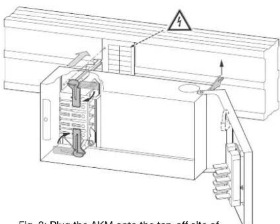
Fig. 3: Plug the AKM onto the tap-off site of the busbar.
- Mount the AKM as shown in the adjacent figure (4). Please note that here too, depending on the national regulations, the tap-off units may be live (see warning symbol).
i INFORMATION
The extremely high diversity in local construction site conditions cannot be illustrated in this document. We therefore recommend that you have the local conditions checked by qualified installation personnel.
- Mount and install your cable to the consumer/equipment as shown in figure (5). Please note that this illustration is only for the assembly and installation of the outgoing cable, the individual phases, the neutral conductor and the protective conductor and does not correspond to the actual, assembled AKM.


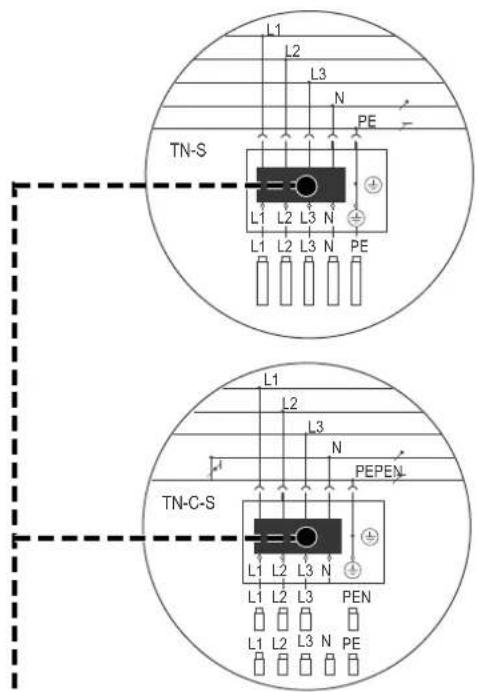
Fig. 6: Connection of the AKM in TN-S and TN-C-S networks
- Insert suitable NH fuses in the fuse sockets provided. Use a suitable NH fuse glove for insertion.
For 125 A version of the AKM only:
- For the 125 A version of the AKM, remove the padlock used to prevent the AKM from closing unexpectedly.
Again, note that depending on the country's electrical installation regulations, the tap-off units may be live.
- Switch on the power supply/voltage of the busbar system of your system and thus put your AKM and the attached consumers into operation.
4.2 Busbar tap-off unit - System BD2 - 250/400/530 A, without cover disconnector
i INFORMATION
The following steps show the assembly of the busbar tap-off unit (system BD2 - 250/400/530 A variants, without cover disconnector), regardless of the equipment/installation. Please note, as already described under „Installation and equipment options – schematic diagrams“ auf S. 68, that the equipment of your busbar tap-off unit and thus the information on the mounting of components and cabling may differ from the following figures!
The 250 A, 400 A and 530 A versions of the AKM have no cover disconnector. The assembly and disassembly of the busbar tap-off unit (AKM) without cover disconnector is only possible when the cover is open.
A finger-safe design provides protection against contact.
For the AKM versions with switching elements (fuse switch or circuit breaker) the cover opens only when the switching element is switched off (interlock)!

Fig. 1: AKM with switching elements
- Use a hexagon socket wrench or other suitable tool to open the busbar tap-off unit (AKM).

i INFORMATION
Check the required space before installing the AKM. Tap-off units must not be placed at connection points over terminal blocks! The space requirements of the AKM must be taken into account already during the project planning stage! Please also observe the further assembly and installation instructions of the busbar system manufacturer.
- The 250/400/530 A versions of the AKM are fixed to the busbar with a mounting aid that is included.
Plug the mounting aid (anti-twist protection - prevents incorrect positioning of the AKM) onto the tap-off site of the busbar system. Please note that depending on the national regulations for electrical installations, mounting the tap-off units while live might or might not be permitted. In the case of live, switch off the voltage and protect the busbar circuit against being switched on again in accordance with local regulations (see warning symbol).

- Adjust the mounting aid (anti-twist protection) on the busbar by folding over the adjustment brackets.

Fig. 4: Adjusting the mounting aid
- Fasten the mounting aid with a hexagon socket wrench or another suitable tool.

Fig. 5: Adjusting the mounting aid
- For final attachment, adjust the AKM using the fixing bolts of the mounting aid (see Fig. 6). Please note that here too, depending on the national regulations, the tap-off sites of the busbars may be live (see warning symbol).

Fig. 6: Adjusting the AKM (1,2)
- Fig. 7 - Flip the lever - engage the AKM: (3) With the lever open, guide the AKM into the bracket opening of the mounting aid. (4) Push the contacts of the AKM into the tap-off site of the busbar and the pins of the lever into the bracket of the mounting aid. (5) Flip the lever (6) until the AKM engages in the bracket of the mounting aid.

i INFORMATION
The extremely high diversity in local construction site conditions cannot be illustrated in this document. We therefore recommend that you have the local conditions checked by qualified installation personnel.
- Please note that with an open AKM, depending on the national regulations, the tap-off sites of the busbars may be live (see warning symbol)!

Fig. 8: AKM open
- Assemble and install your cables to the consumers/operating equipment as shown in the following figures. The illustrations of the actual AKM and the cable outlet may differ!
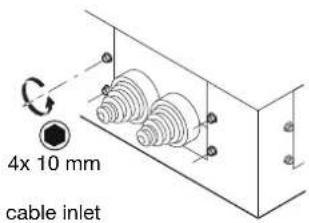
Fig. 9: Opening the cable inlet

natural_image
Technical line drawing of mechanical components including a bracket, screw base, and mounting bracket (no text or symbols)Fig. 10: Removing the cable inlet with cable grommets (strain relief integrated)
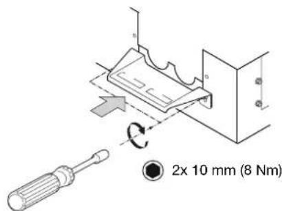
Fig. 11: Mounting the cable holder
natural_image
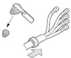
Diagram showing two types of cable or connector assemblies with arrows indicating direction (no text or symbols)Fig. 12: Cut the cable grommets to size according to the cable cross section and feed the cable through

Fig. 13: Mount cable inlet with cable grommets
- Mount and install your cables with cable lugs according to the following illustrations. Please note that this illustration is only for the assembly and installation of the outgoing cable, the individual phases, the neutral conductor and the protective conductor and does not correspond to the actual, assembled AKM.

INFORMATION
Observe the following when mounting and installing cables and lines:
- Manufacturer's information on bending radii of cables and wires.
- Maintain clearance and creepage distances at the connection points. If necessary, take additional measures, such as phase separators and insulation of cable lugs.
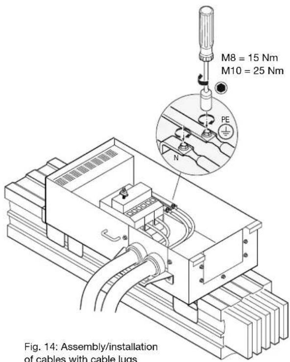

natural_image
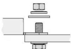
Mechanical assembly diagram showing a bolt and nut assembly (no text or labels)Fig. 15: Connection CU-cable lug with standard connection set
natural_image
Mechanical assembly diagram showing bolted joint and mounting bracket (no text or labels)Fig. 16: Connection AL-cable lug with additional washer according to ISO 7093

INFORMATION
A variant of a circuit diagram / wiring diagram for the AKM can be found in chapter „Circuit diagram / wiring variant“ auf S. 78.
Fig. 17: Connection of the AKM in TN-S and TN-C-S networks
- Close and mount the cover of the AKM according to the following illustration:

-
Insert suitable NH fuses in the fuse sockets provided. Use a suitable NH fuse glove for insertion.
-
Switch on the power supply/voltage of the busbar system of your system and thus put your AKM and the attached consumers into operation.
5. Installation
5.1 Circuit diagram / wiring variant
The following circuit diagram shows a wiring variant of the AKM busbar tap-off unit.
The wiring depends on the selected AKM variant and thus on the installed measurement devices and components.

flowchart
graph TD
    subgraph Busbar
        L1 --> S2
        L2 --> S2
        L3 --> S2
        N --> S1
        PE --> S1
    end

    subgraph Sensor
        PT100 --> Temperature["Analog input"]
        Current["Analog input"] --> Voltage["Analog input"]
        CurrentMeasurement["Analog input"] --> CurrentMeasurement["Analog Input"]
        CurrentMeasurement --> DigitalInput["Digital input"]
    end

    subgraph Modules
        RJ45 --> A17
        RS485 --> B16
        Matus_cable_h Streaming --> D1
        Matus_cable_h Streaming --> D2
        Matus_cable_h Streaming --> D3
        Matus_cable_h Streaming --> D4
        Matus_cable_h Streaming --> D5
        Matus_cable_h Streaming --> D6
        Matus_cable_h Streaming --> D7
        Matus_cable_h Streaming --> D8
        Matus_cable_h Streaming --> D9
        Matus_cable_h Streaming --> D10
        Matus_cable_h Streaming --> D11
        Matus_cable_h Streaming --> D12
        Matus_cable_h Streaming --> D13
        Matus_cable_h Streaming --> D14
        Matus_cable_h Streaming --> D15
        Matus_cable_h Streaming --> D16
        Matus_cable_h Streaming --> D17
        Matus_cable_h Streaming --> D18
        Matus_cable_h Streaming --> D19
        Matus_cable_h Streaming --> D20
        Matus_cable_h Streaming --> D21
        Matus_cable_h Streaming --> D22
        Matus_cable_h Streaming --> D23
        Matus_cable_h Streaming --> D24
        Matus_cable_h Streaming --> D25
        Matus_cable_h Streaming --> D26
        Matus_cable_h Streaming --> D27
        Matus_cable_h Streaming --> D28
        Matus_cable_h Streaming --> D29
        Matus_cable_h Streaming --> D30
    end

    subgraph Control
        S1 --> CurrentMeasurement["Analog input"]
        S2 --> CurrentMeasurement["Analog input"]
    end

    subgraph Busbar
        L1 --> S2
        L2 --> S2
        L3 --> S1
        N --> S1
        PE --> S1

    end

    E.g. UMG_96RM-E
The figure shows only one example. The enclosed detailed circuit diagram is definitive (depending on measurement device, current and options)
6. Technical data
6.1 Technical data of the busbar tap-off unit
| General | |
| Product designation AKM tap-off unit for busbar trunking system BD2 | |
| Type-approved according to DIN EN 61439 | |
| Protection against foreign matter and water IP34 according to DIN EN 61439-1 | |
| Operating voltage | Type AKM 806: max. 230 V / 400 V (+-10 %)Type AKM 96RME: max. 277 V / 480 V (+-10 %)Type AKM 96RMPN: max. 277 V / 480 V (+-10 %)Type AKM 96PA: max. 277 V / 480 V (+-10 %)Type AKM 96PAMID: max. 277 V / 480 V (+-10 %)Type AKM 96PQL: max. 277 V / 480 V (+-10 %)Type AKM 103: max. 277 V / 480 V (+-10 %) |
| Operating current (depending on device type) Max. 125 A / 250 | A / 400 A / 530 A |
| Ambient temperature range -10 °C to +55 °C | |
| Relative humidity 0 to 75% RH | |
| Operating elevation | 0 to 2000 m above sea level |
| Pollution degree | 2 |
| Mounting orientation | Vertical or horizontal |
| Total power dissipation | 97 W |
| Ventilation | No forced ventilation required |
| Mechanical structure length x width x height | See table „Dimensions“ auf S. 64 |
| Outgoing power feeder | |
| Voltage | Type AKM 806: max. 230 V / 400 V (+-10 %)Type AKM 96RME: max. 277 V / 480 V (+-10 %)Type AKM 96RMPN: max. 277 V / 480 V (+-10 %)Type AKM 96PA: max. 277 V / 480 V (+-10 %)Type AKM 96PAMID: max. 277 V / 480 V (+-10 %)Type AKM 96PQL: max. 277 V / 480 V (+-10 %)Type AKM 103: max. 277 V / 480 V (+-10 %) |
| Maximum permissible current (depending on the device type) | Max. 125 A / 250 A / 400 A / 530 A |
| Load factor, continuous (24 h) | 0.6 |
| Load factor, short-term(2 h) | 1.0 |
| Fuse protection (depending on device type) | 3x NH, max. 125 / 250 / 400 / 530 A |
| Number of conductors | 5 |
| Max. connection cross section | 125 A: 50 mm^2 250/400/530 A: 240 mm^2 |
| Short-circuit resistance | Ensured by NH-fuse |
| Measurement device technical data | |
| Measurement device fuse protection | Motor circuit breaker 6.3 A according to DIN EN IEC 60947-4-1 |
| Further information on the measurement device | See data sheet of the measurement device |
| Digital input: Pulse detection (option) | |
| Type Solid state relays, not short-circuit proof | |
| Maximum counter frequency 20 Hz | |
| Input signal applied 18 V .. 28 V DC (typically 4 mA) | |
| Input signal not applied 0 .. 5 V DC, current less than 0.5 mA | |
| Connection Socket M8, 3-pin | |
| Cable length up to 30 m Unshielded | |
| Cable length greater than 30 m Shielded | |
| Pulse input supply Power supply unit 24 VDC, max. 1.3 A | |
| Temperature measurement | |
| Probes PT100 in close proximity to the NH fuse | |
| Ethernet interface | |
| Connection Han PushPull RJ45 | |
| Protocols | AKM 806: Modbus/TCP, DHCP-Client, SNMP V2cAKM 96RME: TCP/IP, DHCP-Client (BootP),Modbus/TCP (Port 502), ICMP (Ping), NTP,Modbus RTU over Ethernet, FTP, SNMPAKM 96RMPN: TCP/IP, Modbus/TCP (Port 502),CMP (Ping), NTP, Modbus RTU over Ethernet (Port 8000), FTP ProfiNet (SNMP, DCP,MRP, LLDP, DCOM, RPC ...)AKM 96PA: TCP/IP, DHCP-Client (BootP),Modbus/TCP (Port 502), ICMP (Ping), NTPAKM 96PAMID: TCP/IP, DHCP-Client (BootP),Modbus/TCP (Port 502), ICMP (Ping), NTPAKM 96PQL: TCP/IP, DHCP-Client (BootP),Modbus/TCP (Port 502), ICMP (Ping), NTPAKM 103: Modbus RTU/Slave |
| Serial interface | |
| RS-485 - Modbus RTU/Slave | 9.6 / 19.2 / 38.4 / 57.6 / 115.2 kbps |
| Connection M12, 4-pin, A-coded; 1x each socket and plug | |
| Residual current detection | |
| Monitoring device | Internal RCM input of the measurement device;See data sheet of the measurement device |
| Residual currents detected | Type A |
| Enhanced residual current detection (option) | |
| Monitoring device | RCM 202-AB |
| Residual currents detected | Type A / B / B+ |
6.2 Technical data of the installed measurement devices and components
There are many variants of the busbar tap-off units and they can be purchased with different items of equipment and installations.
Consequently, please note the technical data in all usage information which belongs to the installed measurement devices and components!
7. Service and maintenance
i INFORMATION
For the service and maintenance of the BD2 busbar system with busbar tap-off unit and the measurement devices and components installed there, please refer to the relevant usage information of the respective manufacturers.
7.1 Service
For questions not answered or described in this manual, please contact the manufacturer. Please be certain to have the following information ready to answer any questions:
- Device designation (see rating plate).
- Serial number (see rating plate).
- Measured voltage and supply voltage.
- An exact error description.
DANGER
Life-threatening danger or risk of injury due to dangerous voltages!
- Before starting work, also service and maintenance work, disconnect your system and the busbar tap-off unit from the power supply, secure against reconnection, verify that the system is voltage-free, ground and short-circuit, cover or block off adjacent live parts.
- Only qualified electricians and personnel qualified in electrical engineering may perform the work described below [IEC 61439-1; EN 50110-1].
· Comply with country-specific safety regulations and regulations for working near live parts [EN 50110-1]. - Observe additional warnings on the devices and components.
DANGER
Life-threatening danger or risk of injury due to dangerous voltages!
The busbar tap-off unit is live even when the measurement device is removed. Due to the door cutout being open, protection against accidental contact is not ensured.
- Close the cutout in the door of the enclosure with a stable and secure cover.
Janitza®
Janitza electronics GmbH
Vor dem Polstück 6
D-35633 Lahnau
Support tel. +49 6441 9642-22
Email: info@janitza.com


- Supplementary user manual
- Subject to technical changes.
- TABLE OF CONTENTS
- Information on the product and the user manual 48
- Safety 50
- Product description
- Scope of delivery
- Functions 63
- Communication 64
- Device views
- 12 Key system for type designation
- Mounting
- Installation
- Technical data
- Service and maintenance
- Information on the product and the user manual
- Disclaimer
- Copyright notice
- Technical changes
- About this user manual
- i INFORMATION
- Defective products/disposal
- Safety
- Display of warning notices and safety information
- Hazard levels
- DANGER
- WARNING
- CAUTION
- ATTENTION
- Product safety
- Dangers when handling the product
- Electrically qualified personnel
- Warning against unauthorized manipulation or improper use of the devices, modules and components!
- Warranty in the event of damage
- Dangers arising from the busbar tap-off unit
- Life-threatening danger or risk of injury due to dangerous voltages!
- Safety information for handling current transformers and measurement devices with residual current measurement
- Handling batteries/accumulators
- Risk of injury due to fire or burns!
- Product description and application areas
- The AKM busbar tap-off unit
- Incoming goods inspection
- Malfunction, damage or risk of injury due to improper connection of the device and its components.
- Observe all
- Intended use
- Performance characteristics
- EU conformity declaration
- Norms and standards
- Types, variants and options
- AKM 806 - Busbar tap-off unit with UMG 806 measurement device
- AKM 96RME busbar tap-off unit with UMG 96RM-E measurement device
- AKM 103 - Busbar tap-off unit with UMG 103-CBM measurement device
- Not included in delivery:
- Please note!
- Functions
- Energy measurement
- Current measurement
- Residual current measurement (RCM)
- Temperature measurement
- Power input, cover disconnector and protection against contact
- Power output
- Communication
- INFORMATION
- Ethernet interface (standard, exception AKM 103)
- RS-485 interface (standard)
- Digital input (option)
- The following types have the "digital input" option:
- View - front and bottom
- Key system for type designation
- AKM xxx-yyy-zzz-ooo
- Identification of the device (rating plate)
- Installation and equipment options - schematic diagrams
- Busbar tap-off unit – System BD2 - 125 A, with cover disconnector
- Busbar tap-off unit - System BD2 - 250/400/530 A, without cover disconnector
- Circuit diagram / wiring variant
- Technical data of the installed measurement devices and components
- Service
- Janitza®
Brand : Janitza
Model : AKM 806
Category : Industrial electrical device