VigorSwitch G1080 - Switch Draytek - Free user manual and instructions
Find the device manual for free VigorSwitch G1080 Draytek in PDF.


| Product Type | Network Switch |
| Brand | Draytek |
| Model | VigorSwitch G1080 |
| Ports | 8 x Gigabit Ethernet (10/100/1000 Mbps) |
| Switch Type | Unmanaged |
| Auto-MDI/MDIX | Yes, on all ports |
| Dimensions (W x D x H) | 200 x 120 x 30 mm |
| Weight | 0.5 kg |
| Power Supply | 5V DC, 1A |
| Power Consumption | ≤ 5W |
| Operating Temperature | 0°C to 40°C |
| Storage Temperature | -10°C to 70°C |
| Humidity | 10% to 90% non-condensing |
| LED Indicators | Power, Link/Activity per port |
| Mounting | Desktop or wall-mountable |
| Cooling | Fanless (passive) |
| Noise Level | 0 dB (silent) |
| Cleaning | Wipe with a soft dry cloth; do not use liquids |
| Safety | Keep away from water and moisture |
| Repairability | Not user-serviceable; no spare parts available |
Frequently Asked Questions - VigorSwitch G1080 Draytek
User questions about VigorSwitch G1080 Draytek
0 question about this device. Answer the ones you know or ask your own.
Ask a new question about this device
Download the instructions for your Switch in PDF format for free! Find your manual VigorSwitch G1080 - Draytek and take your electronic device back in hand. On this page are published all the documents necessary for the use of your device. VigorSwitch G1080 by Draytek.
USER MANUAL VigorSwitch G1080 Draytek
Smart Lite Gigabit Switch


natural_image
Front view of a DRayTek ViperSwitch G1080 network switch with ports and indicator lights, set against a red background (no readable text beyond branding)Your reliable networking solutions partner
User's Guide
V1.0
VigorSwitch G1080 Smart Lite Giga Switch User's Guide
Version: 1.0
Firmware Version: V1.04.04
Date: June 5, 2018
(For future update, please visit DrayTek web site for further information)
Intellectual Property Rights (IPR) Information
Copyrights
© All rights reserved. This publication contains information that is protected by copyright. No part may be reproduced, transmitted, transcribed, stored in a retrieval system, or translated into any language without written permission from the copyright holders.
Trademarks
The following trademarks are used in this document:
● Microsoft is a registered trademark of Microsoft Corp.
● Windows, Windows 95, 98, Me, NT, 2000, XP, 7 and Explorer are trademarks of Microsoft Corp.
● Apple and Mac OS are registered trademarks of Apple Inc.
● Other products may be trademarks or registered trademarks of their respective manufacturers.
Caution and Electronic Emission Notices
Caution
Circuit devices are sensitive to static electricity, which can damage their delicate electronics. Dry weather conditions or walking across a carpeted floor may cause you to acquire a static electrical charge.
To protect your device, always:
- Touch the metal chassis of your computer to ground the static electrical charge before you pick up the circuit device.
- Pick up the device by holding it on the left and right edges only.
Warranty
We warrant to the original end user (purchaser) that the device will be free from any defects in workmanship or materials for a period of one (1) years from the date of purchase from the dealer. Please keep your purchase receipt in a safe place as it serves as proof of date of purchase. During the warranty period, and upon proof of purchase, should the product have indications of failure due to faulty workmanship and/or materials, we will, at our discretion, repair or replace the defective products or components, without charge for either parts or labor, to whatever extent we deem necessary tore-store the product to proper operating condition. Any replacement will consist of a new or re-manufactured functionally equivalent product of equal value, and will be offered solely at our discretion. This warranty will not apply if the product is modified, misused, tampered with, damaged by an act of God, or subjected to abnormal working conditions. The warranty does not cover the bundled or licensed software of other vendors. Defects which do not significantly affect the usability of the product will not be covered by the warranty. We reserve the right to revise the manual and online documentation and to make changes from time to time in the contents hereof without obligation to notify any person of such revision or changes.
Be a Registered Owner
Web registration is preferred. You can register your Vigor device via http://www.draytek.com.
Firmware & Tools Updates
Due to the continuous evolution of DrayTek technology, all devices will be regularly upgraded. Please consult the DrayTek web site for more information on newest firmware, tools and documents.
http://www.draytek.com
Table of Contents
Chapter 1: Introduction....1
1.1 Overview .... 1
1.2 Features.... 1
1.3 Packing List....2
1.4 LED Indicators and Connectors 3
1.5 Hardware Installation 4
1.5.1 Configuring the Management Agent of Switch 6
1.5.2 IP Address Assignment 7
1.6 Typical Applications....11
Chapter 2: Basic Concept and Management....13
2.1 What's the Ethernet.... 13
2.2 Media Access Control (MAC) 15
2.3 Flow Control 20
Chapter 3: Operation of Web-based Management....23
3.1 Web Management Home Overview 24
3.2 System Information 25
3.3 Port Statistics 26
3.4 Link Aggregation 26
3.5 VLAN 27
3.6 Multicast 28
3.7 QoS 29
3.8 Rate Limiting 31
3.9 Storm Control 32
3.10 Loop Prevention 33
3.11 Port Mirroring.... 34
3.12 System Maintenance.... 35
Chapter 4: Trouble Shooting....37
4.1 Resolving No Link Condition.... 37
4.2 Q & A 37
Chapter 1: Introduction
1.1 Overview
VigorSwitch G1080 is a standard switch that meets all IEEE 802.3/u/x/z Gigabit, Fast Ethernet specifications. The switch has 8 10/100/1000Mbps TP ports. It supports http interface for switch management. The network administrator can log on the switch to monitor, configure and control each port's activity. In addition, the switch implements the QoS (Quality of Service), VLAN, and Trunking. It is suitable for office application.
10/100/1000Mbps TP is a standard Ethernet port that meets all IEEE 802.3/u/x/z Gigabit, Fast Ethernet specifications. 1000Mbps SFP Fiber transceiver is a Gigabit Ethernet port that fully complies with all IEEE 802.3z and 1000Base-SX/LX standards.
Below shows key features of this device:
QoS
The switch offers powerful QoS function. This function supports 802.1p VLAN tag priority and DSCP on Layer 3 of network framework.
VLAN
Support IEEE802.1Q Tag-based VLAN. Support 8 active VLANs and VLAN ID 1\~4094.
Port Trunking
Allows one or more links to be aggregated together to form a Link Aggregation Group by the static setting.
1.2 Features
The VigorSwitch G1080, a standalone off-the-shelf switch, provides the comprehensive features listed below for users to perform system network administration and efficiently and securely serve your network.
Hardware
● 8 10/100/1000Mbps Auto-negotiation Gigabit Ethernet TP ports
- Jumbo frame support 9KB
● Programmable classifier for QoS (Layer 2)
- 8K MAC address and support VLAN ID(1\~4094)
● Per-port shaping, policing, and Broadcast Storm Control
● Full-duplex flow control (IEEE802.3x) and half-duplex backpressure
- Extensive front-panel diagnostic LEDs; System: Power, TP Port1-8: LINK/ACT, 10/100/1000Mbps
Management
● Supports per port traffic monitoring counters
● Supports a snapshot of the system Information when you login
● Supports port mirror function
● Supports the static trunk function
● Supports 802.1Q VLAN
● Maximal packet length can be up to 9600 bytes for jumbo frame application
● Supports Broadcasting Suppression to avoid network suspended or crashed
● Supports to send the trap event while monitored events happened
● Supports default configuration which can be restored to overwrite the current configuration which is working on via Web UI and Reset button of the switch
● Built-in web-based management, providing a more convenient UI for the user
1.3 Packing List
Before you start installing the switch, verify that the package contains the following:
● VigorSwitch G1080
- AC Power Cord
- Quick Start Guide
Please notify your sales representative immediately if any of the aforementioned items is missing or damaged.
1.4 LED Indicators and Connectors
Before you use the Vigor device, please get acquainted with the LED indicators and connectors first.
There are 8 Ethernet ports on the front panel of the switch. LED display area, locating on the front panel, contains an ACT, Power LED and 8 ports working status of the switch.
LED Explanation

| LED | Color | Explanation |
| PWR/SYS | On (Green) | The switch is powered on and runs normally. |
| Off | The switch is not ready or is failed. | |
| RJ 45LNK/ACT forPorts 1 ~ 8 | On (Green) | The device is connected with 1000Mbps. |
| On (Amber) The | device is connected with 10/100Mbps. | |
| Blinking The system is sending or receiving data through the port. | ||
| Off The port is disconnected or the link is failed. | ||
Connector Explanation

natural_image
Close-up of a computer monitor with a small display showing 'DC 5V' and a small icon labeled 'R', no readable text or symbols beyond the label.| Interface Description | |
| Security hole. | |
 | Connector for a power adapter. |
1.5 Hardware Installation
Case 1: All switch ports are in the same local area network.
Every port can access each other. (*The switch image is sample only.)
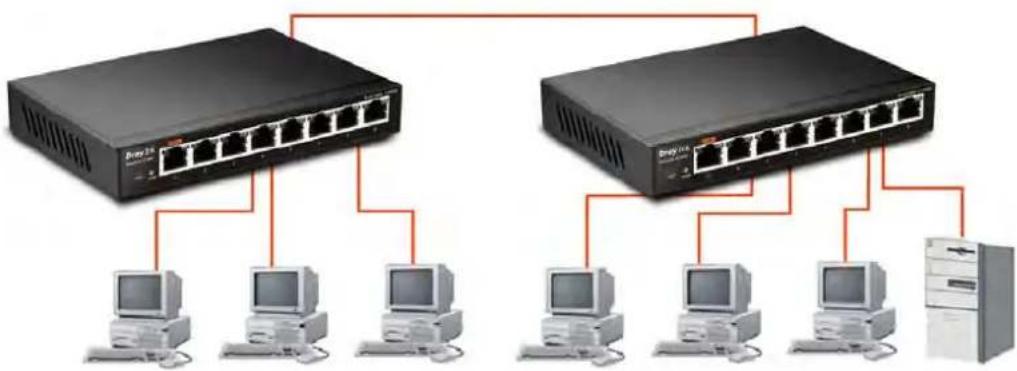
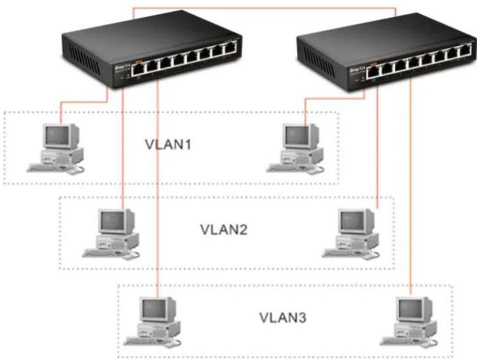
If VLAN is enabled and configured, each node in the network that can communicate each other directly is bounded in the same VLAN area.
Case 2: The same VLAN members can be at different switches with the same VID
flowchart
graph TD
    A["Switch 1"] --> B["Computer"]
    C["Switch 1"] --> D["Computer"]
    E["Switch 1"] --> F["Computer"]
    G["Switch 1"] --> H["Computer"]
    I["Switch 1"] --> J["Computer"]
    K["Switch 1"] --> L["Computer"]
    M["Switch 1"] --> N["Computer"]
    O["Switch 1"] --> P["Computer"]
    Q["Switch 1"] --> R["Computer"]
    S["Switch 1"] --> T["Computer"]
    U["Switch 1"] --> V["Computer"]
    W["Switch 1"] --> X["Computer"]
    Y["Switch 1"] --> Z["Computer"]
    AA["Switch 1"] --> AB["Computer"]
    AC["Switch 1"] --> AD["Computer"]
    AE["Switch 1"] --> AF["Computer"]
    AG["Switch 1"] --> AH["Computer"]
    AI["Switch 1"] --> AJ["Computer"]
    AK["Switch 1"] --> AL["Computer"]
    AM["Switch 1"] --> AN["Computer"]
    AO["Switch 1"] --> AP["Computer"]
    AQ["Switch 1"] --> AR["Computer"]
    AS["Switch 1"] --> AT["Computer"]
    AU["Switch 1"] --> AV["Computer"]
    AW["Switch 1"] --> AX["Computer"]
    AY["Switch 2"] --> Z
    AZ["Switch 2"] --> AA
    BA["Switch 2"] --> AB
    BB["Switch 2"] --> AC
    BC["Switch 2"] --> AD
    BD["Switch 2"] --> AE
    BE["Switch 2"] --> AF
    BF["Switch 2"] --> AG
    BG["Switch 2"] --> AH
    BH["Switch 2"] --> AI
    BI["Switch 2"] --> AJ
    BJ["Switch 2"] --> AK
    BK["Switch 2"] --> AL
    BM["Switch 2"] --> AF
    BN["Switch 2"] --> AA
    BO["Switch 2"] --> AB
    BP["Switch 2"] --> AC
    BZ["Switch 3"] --> AA
    CA["Switch 3"] --> AB
    CB["Switch 3"] --> AC
    CC["Switch 3"] --> AD
    DD["Switch 3"] --> AE
    EE["Switch 3"] --> AF
    FF["Switch 3"] --> AG
    GG["Switch 3"] --> AH
    ID["VLAN1"] --> A
    EV["VLAN2"] --> A
    AF["VLAN3"] --> BB
    AF["VLAN3"] --> BC
Desktop Installation
-
Install the switch on a level surface that can support the weight of the unit and the relevant components.
-
Plug the switch with the female end of the provided power cord and plug the male end to the power outlet.
Installing Network Cables
- Crossover or straight-through cable: All the ports on the switch support Auto-MDI/MDI-X functionality. Both straight-through or crossover cables can be used as the media to connect the switch with PCs as well as other devices like switches, hubs or router.
- Category 3, 4, 5 or 5e, 6 UTP/STP cable: To make a valid connection and obtain the optimal performance, an appropriate cable that corresponds to different transmitting/receiving speed is required. To choose a suitable cable, please refer to the following table.
| Media | Speed | Wiring |
| 10/100/1000 Mbps copper | 10 Mbps Category 3,4,5 UTP/STP | |
| 100Mbps | Category 5 UTP/STP | |
| 1000 Mbps Category 5e, 6 UTP/STP | ||
1.5.1 Configuring the Management Agent of Switch
Users can monitor and configure the switch through the following procedures.
Configuring the Management Agent of VigorSwitch G1080 through the Ethernet Port.
Web-based UI for the switch is an interface in a highly friendly way to configure and monitor the switch through the switch's Ethernet port.
VigorSwitch, for example:
IP Address: 192.168.1.224
Subnet Mask: 255.255.255.0
Default Gateway: 192.168.1.254
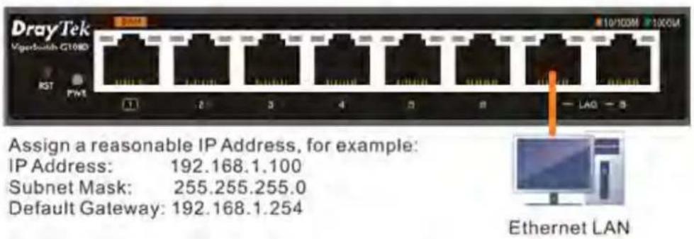
Managing VigorSwitch G1080 through Ethernet Port
Before start using the switch, the IP address setting of the switch should be done, then perform the following steps:
- Set up a physical path between the configured the switch and a PC by a qualified UTP Cat. 5 cable with RJ-45 connector.
Note: If PC directly connects to the switch, you have to setup the same subnet mask between them. But, subnet mask may be different for the PC in the remote site. Please refer to the above figure about the 24-Port GbE Smart Lite Switch default IP address information.
- Run web browser and follow the menu. Please refer to Chapter 3.
1.5.2 IP Address Assignment
For IP address configuration, there are three parameters needed to be filled in. They are IP address, Subnet Mask, Default Gateway and DNS.
IP address:
The address of the network device in the network is used for internetworking communication. Its address structure looks is shown below. It is “classful” because it is split into predefined address classes or categories.
Each class has its own network range between the network identifier and host identifier in the 32 bits address. Each IP address comprises two parts: network identifier (address) and host identifier (address). The former indicates the network where the addressed host resides, and the latter indicates the individual host in the network which the address of host refers to. And the host identifier must be unique in the same LAN. Here the term of IP address we used is version 4, known as IPv4.
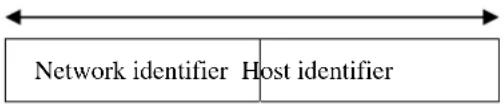
With the classful addressing, it divides IP address into three classes, class A, class B and class C. The rest of IP addresses are for multicast and broadcast. The bit length of the network prefix is the same as that of the subnet mask and is denoted as IP address/X, for example, 192.168.1.0/24. Each class has its address range described below.
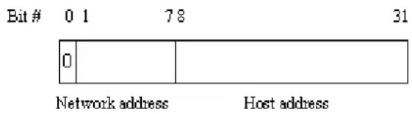
Class A:
Address is less than 126.255.255.255. There are a total of 126 networks can be defined because the address 0.0.0.0 is reserved for default route and 127.0.0.0/8 is reserved for loopback function.
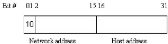
Class B:
IP address range between 128.0.0.0 and 191.255.255.255. Each class B network has a 16-bit network prefix followed 16-bit host address. There are 16,384 (2^14)/16 networks able to be defined with a maximum of 65534 (2^16 - 2) hosts per network.
Class C:
IP address range between 192.0.0.0 and 223.255.255.255. Each class C network has a 24-bit network prefix followed 8-bit host address. There are 2,097,152 (2^21)/24 networks able to be defined with a maximum of 254 (2^8 -2) hosts per network.
Bit#0123
23 24 31

Network address
Host address
Class D and E:
Class D is a class with first 4 MSB (Most significance bit) set to 1-1-1-0 and is used for IP Multicast. See also RFC 1112. Class E is a class with first 4 MSB set to 1-1-1-1 and is used for IP broadcast.
According to IANA (Internet Assigned Numbers Authority), there are three specific IP address blocks reserved and able to be used for extending internal network. We call it Private IP address and list below:
Class A 10.0.0.0 --- 10.255.255.255
Class B 172.16.0.0 --- 172.31.255.255
Class C 192.168.0.0 --- 192.168.255.255
Please refer to RFC 1597 and RFC 1466 for more information.
Subnet mask:
It means the sub-division of a class-based network or a CIDR block. The subnet is used to determine how to split an IP address to the network prefix and the host address in bitwise basis. It is designed to utilize IP address more efficiently and ease to manage IP network.
For a class B network, 128.1.2.3, it may have a subnet mask 255.255.0.0 in default, in which the first two bytes is with all 1s. This means more than 60 thousands of nodes in flat IP address will be at the same network. It’s too large to manage practically. Now if we divide it into smaller network by extending network prefix from 16 bits to, say 24 bits, that’s using its third byte to subnet this class B network. Now it has a subnet mask 255.255.255.0, in which each bit of the first three bytes is 1. It’s now clear that the first two bytes is used to identify the class B network, the third byte is used to identify the subnet within this class B network and, of course, the last byte is the host number.
Not all IP address is available in the sub-netted network. Two special addresses are reserved. They are the addresses with all zero's and all one's host number. For example, an IP address 128.1.2.128, what IP address reserved will be looked like? All 0s mean the network itself, and all 1s mean IP broadcast.
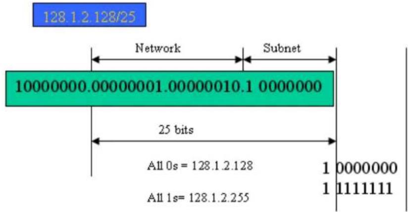
In this diagram, you can see the subnet mask with 25-bit long, 255.255.255.128, contains 126 members in the sub-netted network. Another is that the length of network prefix equals the number of the bit with 1s in that subnet mask. With this, you can easily count the number of IP addresses matched. The following table shows the result.
| Prefix Length No. of IP matched No. of Addressable IP | ||
| /32 | 1 | |
| /31 | 2 | |
| /30 | 4 | |
| /29 | 8 | |
| /28 | 16 | |
| /27 | 32 | |
| /26 | 64 | |
| /25 | 128 | 126 |
| /24 | 256 | 254 |
| /23 | 512 | 510 |
| /22 | 1024 | 1022 |
| /21 | 2048 | 2046 |
| /20 | 4096 | 4094 |
| /19 | 8192 | 8190 |
| /18 | 16384 | 16382 |
| /17 | 32768 | 32766 |
| /16 | 65536 | 65534 |
-
2 6 14 30 62
According to the scheme above, a subnet mask 255.255.255.0 will partition a network with the class C. It means there will have a maximum of 254 effective nodes existed in this sub-netted network and is considered a physical network in an autonomous network. So it owns a network IP address which may looks like 168.1.2.0.
With the subnet mask, a bigger network can be cut into small pieces of network. If we want to have more than two independent networks in a worknet, a partition to the network must be performed. In this case, subnet mask must be applied.
For different network applications, the subnet mask may look like 255.255.255.240. This means it is a small network accommodating a maximum of 15 nodes in the network.
Default gateway:
For the routed packet, if the destination is not in the routing table, all the traffic is put into the device with the designated IP address, known as default router. Basically, it is a routing policy. The gateway setting is used for Trap Events Host only in the switch.
For assigning an IP address to the switch, you just have to check what the IP address of the network will be connected with the switch. Use the same network address and append your host address to it.
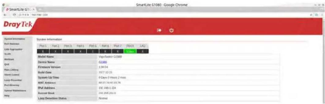
First, IP Address: as shown above, enter "192.168.1.224", for instance. For sure, an IP address such as 192.168.1.x must be set on your PC.
Second, Subnet Mask: as shown above, enter "255.255.255.0". Any subnet mask such as 255.255.255.x is allowable in this case.
Note: The DHCP Setting is enabled in default.
1.6 Typical Applications
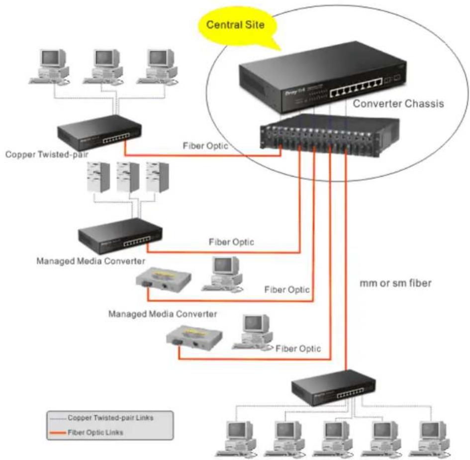
The VigorSwitch implements 8 Gigabit Ethernet TP ports with auto MDIX and two slots for the removable module supporting comprehensive fiber types of connection including LC and BiDi-LC SFP modules. The switch is suitable for the following applications.
➢ Central Site/Remote site application is used in carrier or ISP
flowchart
graph TD
    A["Central Site"] --> B["Copper Twisted-pair"]
    A --> C["Converter Chassis"]
    B --> D["Managed Media Converter"]
    C --> E["Converter Chassis"]
    D --> F["Managed Media Converter"]
    E --> G["Converter Chassis"]
    F --> H["mm or sm fiber"]
    G --> H
    H --> I["Copper Twisted-pair Links"]
    H --> J["Fiber Optic Links"]
    style A fill:#f9f,stroke:#333
    style B fill:#ccf,stroke:#333
    style C fill:#ccf,stroke:#333
    style D fill:#cfc,stroke:#333
    style E fill:#cfc,stroke:#333
    style F fill:#fcc,stroke:#333
    style G fill:#fcc,stroke:#333
    style H fill:#ffc,stroke:#333
It is a system wide basic reference connection diagram. This diagram demonstrates how the switch connects with other network devices and hosts.
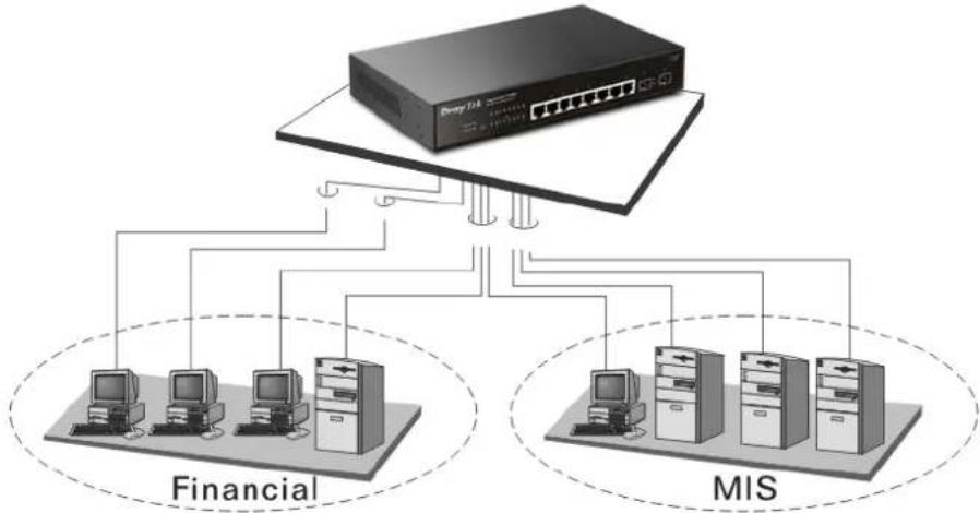
➢ Peer-to-peer application is used in two remote offices
flowchart
graph TD
    A["Server 14"] --> B["Financial"]
    A --> C["MIS"]
    B --> D["Computer 1"]
    B --> E["Computer 2"]
    B --> F["Computer 3"]
    B --> G["Computer 4"]
    C --> H["Computer 5"]
    C --> I["Computer 6"]
    C --> J["Computer 7"]
    C --> K["Computer 8"]
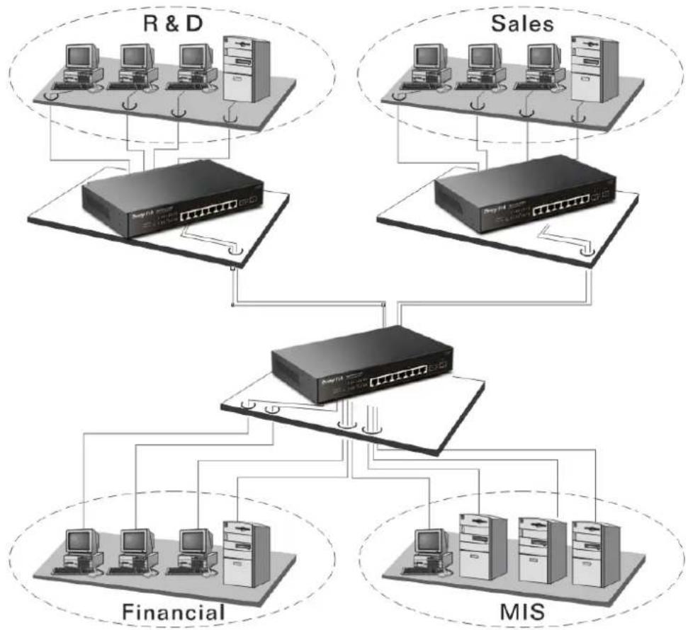
▶ Office network
flowchart
graph TD
    subgraph R & D
        A["Computer 1"] --> B["Switch"]
        C["Computer 2"] --> B
        D["Computer 3"] --> B
        B --> E["Network"]
    end
    subgraph Sales
        F["Computer 1"] --> G["Switch"]
        H["Computer 2"] --> G
        I["Computer 3"] --> G
        G --> J["Network"]
    end
    subgraph Financial
        K["Computer 1"] --> L["Switch"]
        M["Computer 2"] --> L
        N["Computer 3"] --> L
        L --> O["Network"]
    end
    subgraph MIS
        P["Computer 1"] --> Q["Switch"]
        R["Computer 2"] --> Q
        S["Computer 3"] --> Q
        Q --> T["Network"]
    end
Chapter 2: Basic Concept and Management
This chapter will tell you the basic concept of features to manage this switch and how they work.
2.1 What's the Ethernet
Ethernet originated and was implemented at Xerox in Palo Alto, CA in 1973 and was successfully commercialized by Digital Equipment Corporation (DEC), Intel and Xerox (DIX) in 1980. In 1992, Grand Junction Networks unveiled a new high speed Ethernet with the same characteristic of the original Ethernet but operated at 100Mbps, called Fast Ethernet now. This means Fast Ethernet inherits the same frame format, CSMA/CD, software interface. In 1998, Gigabit Ethernet was rolled out and provided 1000Mbps. Now 10G/s Ethernet is under approving. Although these Ethernet have different speed, they still use the same basic functions. So they are compatible in software and can connect each other almost without limitation. The transmission media may be the only problem.
flowchart
graph TD
    A["Application"] --> B["Presentation"]
    B --> C["Session"]
    C --> D["Transport"]
    D --> E["Network"]
    E --> F["Data link"]
    F --> G["Physical"]

    subgraph Upper-layer protocols
        H["MAC-client"] --> I["Media Access (MAC)"]
    end

    J["IEEE 802-specific"] --> K["IEEE 802.3-specific"]
    K --> L["Media-specific"]

    style A fill:#f9f,stroke:#333
    style B fill:#f9f,stroke:#333
    style C fill:#f9f,stroke:#333
    style D fill:#f9f,stroke:#333
    style E fill:#f9f,stroke:#333
    style F fill:#f9f,stroke:#333
    style G fill:#f9f,stroke:#333
    style H fill:#ccf,stroke:#333
    style I fill:#ccf,stroke:#333
    style J fill:#ccf,stroke:#333
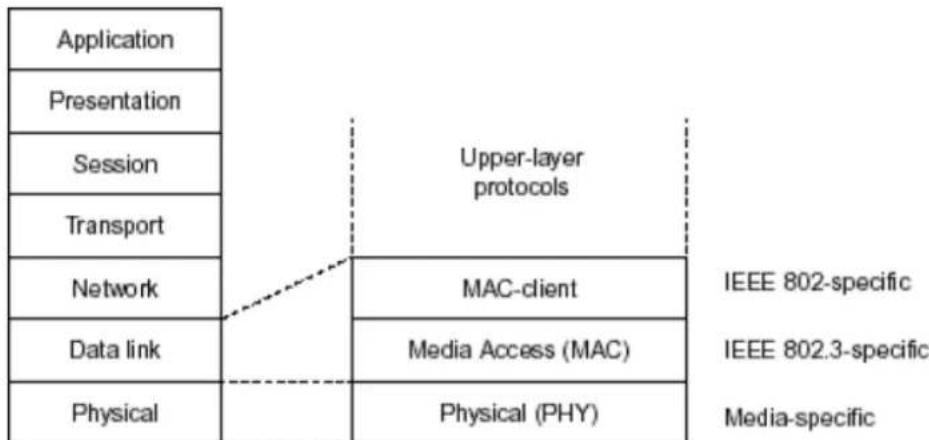
In the above figure, we can see that Ethernet locates at the Data Link layer and Physical layer and comprises three portions, including logical link control (LLC), media access control (MAC), and physical layer. The first two comprises Data link layer, which performs splitting data into frame for transmitting, receiving acknowledge frame, error checking and re-transmitting when not received correctly as well as provides an error-free channel upward to network layer.
flowchart
graph TD
    A["IEEE 802.2 LLC"] --> B["IEEE802.3 CSMA/CD MAC"]
    B --> C["IEEE 802.3 PLS"]
    B --> D["CS"]
    C --> E["IEEE 802.3 MAU"]
    D --> F["ANSI X3T9.5 PMD"]
    E --> G["Coaxial/STP/UTP"]
    F --> H["Fiber"]
    I["Data Link Layer"] --> A
    J["Physical Layer"] --> C
    K["MII"] --> F
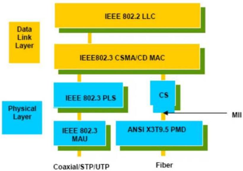
This above diagram shows the Ethernet architecture, LLC sub-layer and MAC sub-layer, which are responded to the Data Link layer, and transceivers, which are responded to the Physical layer in OSI model. In this section, we are mainly describing the MAC sub-layer.
Logical Link Control (LLC)
Data link layer is composed of both the sub-layers of MAC and MAC-client. Here MAC client may be logical link control or bridge relay entity.
Logical link control supports the interface between the Ethernet MAC and upper layers in the protocol stack, usually Network layer, which is nothing to do with the nature of the LAN. So it can operate over other different LAN technology such as Token Ring, FDDI and so on. Likewise, for the interface to the MAC layer, LLC defines the services with the interface independent of the medium access technology and with some of the nature of the medium itself.
| DSAP address | SSAP address | Control | Information |
| 8 bits | 8 bits | 8 or 16 bits | M*8 bits |
| AP address | = | Destination service access point address field | |
| AP address | = | Source service access point address field | |
| ntrol | = | Control field [16 bits for formats that include sequence numbering, and 8 bits for formats that do rot (see 5.2)] | |
| formation | = | Information field | |
| = | Multiplication | ||
| = | An integer value equal to or greater than 0. (Upper bound of M is a function of the medium access control methodology used.) | ||
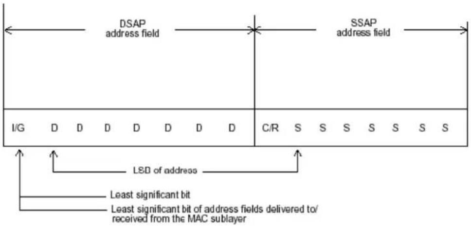
The table above is the format of LLC PDU. It comprises four fields, DSAP, SSAP, Control and Information. The DSAP address field identifies the one or more service access points, in which the I/G bit indicates it is individual or group address. If all bit of DSAP is 1s, it's a global address. The SSAP address field identifies the specific services indicated by C/R bit
(command or response). The DSAP and SSAP pair with some reserved values indicates some well-known services listed in the table below.
| 0xAAAA | SNAP |
| 0xE0E0 | Novell IPX |
| 0xF0F0 | NetBios |
| 0xFEFE | IOS network layer PDU |
| 0xFFFF | Novell IPX 802.3 RAW packet |
| 0x4242 | STP BPDU |
| 0x0606 | IP |
| 0x9898 | ARP |
LLC type 1 connectionless service, LLC type 2 connection-oriented service and LLC type 3 acknowledge connectionless service are three types of LLC frame for all classes of service. In Fig 3-2, it shows the format of Service Access Point (SAP). Please refer to IEEE802.2 for more details.
I/G = 0 Individual DSAP
I/G = 1 Group DSAP
C/R = 0 Command
C/R = 1 Response
XODDDDDD DSAP address
XOSSSSS SSAP address
X1DDDDDD Reserved for ISO definition
X1SSSSSS Reserved for ISO definition
2.2 Media Access Control (MAC)
MAC Addressing
Because LAN is composed of many nodes, for the data exchanged among these nodes, each node must have its own unique address to identify who should send the data or should receive the data. In OSI model, each layer provides its own mean to identify the unique address in some form, for example, IP address in network layer.
The MAC is belonged to Data Link Layer (Layer 2), the address is defined to be a 48-bit long and locally unique address. Since this type of address is applied only to the Ethernet LAN media access control (MAC), they are referred to as MAC addresses.
The first three bytes are Organizational Unique Identifier (OUI) code assigned by IEEE. The last three bytes are the serial number assigned by the vendor of the network device. All these six bytes are stored in a non-volatile memory in the device. Their format is as the following table and normally written in the form as aa-bb-cc-dd-ee-ff, a 12 hexadecimal digits separated by hyphens, in which the aa-bb-cc is the OUI code and the dd-ee-ff is the serial number assigned by manufacturer.
Bit 47 Bit 0
The first bit of the first byte in the Destination address (DA) determines the address to be a Unicast (0) or Multicast frame (1), known as I/G bit indicating individual (0) or group (1). So the 48-bit address space is divided into two portions, Unicast and Multicast. The second bit is for global-unique (0) or locally-unique address. The former is assigned by the device manufacturer, and the later is usually assigned by the administrator. In practice, global-unique addresses are always applied.
A unicast address is identified with a single network interface. With this nature of MAC address, a frame transmitted can exactly be received by the target an interface the destination MAC points to.
A multicast address is identified with a group of network devices or network interfaces. In Ethernet, a many-to-many connectivity in the LANs is provided. It provides a mean to send a frame to many network devices at a time. When all bit of DA is 1s, it is a broadcast, which means all network device except the sender itself can receive the frame and response.
Ethernet Frame Format
There are two major forms of Ethernet frame, type encapsulation and length encapsulation, both of which are categorized as four frame formats 802.3/802.2 SNAP, 802.3/802.2, Ethernet II and Netware 802.3 RAW. We will introduce the basic Ethernet frame format defined by the IEEE 802.3 standard required for all MAC implementations. It contains seven fields explained below.
PRE SFD DA SA Type/Length Data Pad bit if any FCS
7 7 6 6 2 46-1500 4
Preamble (PRE) - The PRE is 7-byte long with alternating pattern of ones and zeros used to tell the receiving node that a frame is coming, and to synchronize the physical receiver with the incoming bit stream. The preamble pattern is:
10101010 10101010 10101010 10101010 10101010 10101010 10101010 10101010
Start-of-frame delimiter (SFD) - The SFD is one-byte long with alternating pattern of ones and zeros, ending with two consecutive 1-bits. It immediately follows the preamble and uses the last two consecutive 1s bit to indicate that the next bit is the start of the data packet and the left-most bit in the left-most byte of the destination address. The SFD pattern is 10101011.
Destination address (DA) - The DA field is used to identify which network device(s) should receive the packet. It is a unique address. Please see the section of MAC addressing.
Source addresses (SA) - The SA field indicates the source node. The SA is always an individual address and the left-most bit in the SA field is always 0.
Length/Type - This field indicates either the number of the data bytes contained in the data field of the frame, or the Ethernet type of data. If the value of first two bytes is less than or equal to 1500 in decimal, the number of bytes in the data field is equal to the Length/Type value, i.e. this field acts as Length indicator at this moment. When this field acts as Length, the frame has optional fields for 802.3/802.2 SNAP encapsulation, 802.3/802.2 encapsulation and Netware 802.3 RAW encapsulation. Each of them has different fields following the Length field.
If the Length/Type value is greater than 1500, it means the Length/Type acts as Type. Different type value means the frames with different protocols running over Ethernet being sent or received.
For example,
| 0x0800 | IP datagram |
| 0x0806 | ARP |
| 0x0835 | RARP |
| 0x8137 | IPX datagram |
| 0x86DD | IPv6 |
Data - Less than or equal to 1500 bytes and greater or equal to 46 bytes. If data is less than 46 bytes, the MAC will automatically extend the padding bits and have the payload be equal to 46 bytes. The length of data field must equal the value of the Length field when the Length/Type acts as Length.
Frame check sequence (FCS) - This field contains a 32-bit cyclic redundancy check (CRC) value, and is a check sum computed with DA, SA, through the end of the data field with the following polynomial.
$$ \mathrm{G} (\mathrm{x}) = \mathrm{x} ^ {3 2} + \mathrm{x} ^ {2 6} + \mathrm{x} ^ {2 3} + \mathrm{x} ^ {2 2} + \mathrm{x} ^ {1 6} + \mathrm{x} ^ {1 2} + \mathrm{x} ^ {1 1} + \mathrm{x} ^ {1 0} + \mathrm{x} ^ {8} + \mathrm{x} ^ {7} + \mathrm{x} ^ {5} + \mathrm{x} ^ {4} + \mathrm{x} ^ {2} + \mathrm{x} + 1 $$
It is created by the sending MAC and recalculated by the receiving MAC to check if the packet is damaged or not.
How does a MAC work?
The MAC sub-layer has two primary jobs to do:
- Receiving and transmitting data. When receiving data, it parses frame to detect error; when transmitting data, it performs frame assembly.
- Performing Media access control. It prepares the initiation jobs for a frame transmission and makes recovery from transmission failure.
Frame transmission
As Ethernet adopted Carrier Sense Multiple Access with Collision Detect (CSMA/CD), it detects if there is any carrier signal from another network device running over the physical medium when a frame is ready for transmission. This is referred to as sensing carrier, also "Listen". If there is signal on the medium, the MAC defers the traffic to avoid a transmission collision and waits for a random period of time, called backoff time, then sends the traffic again.
After the frame is assembled, when transmitting the frame, the preamble (PRE) bytes are inserted and sent first, then the next, Start of frame Delimiter (SFD), DA, SA and through
the data field and FCS field in turn. The followings summarize what a MAC does before transmitting a frame.
- MAC will assemble the frame. First, the preamble and Start-of-Frame delimiter will be put in the fields of PRE and SFD, followed DA, SA, tag ID if tagged VLAN is applied, Ethertype or the value of the data length, and payload data field, and finally put the FCS data in order into the responded fields.
- Listen if there is any traffic running over the medium. If yes, wait.
- If the medium is quiet, and no longer senses any carrier, the MAC waits for a period of time, i.e. inter-frame gap time to have the MAC ready with enough time and then start transmitting the frame.
- During the transmission, MAC keeps monitoring the status of the medium. If no collision happens until the end of the frame, it transmits successfully. If there is a collision happened, the MAC will send the patterned jamming bit to guarantee the collision event propagated to all involved network devices, then wait for a random period of time, i.e. backoff time. When backoff time expires, the MAC goes back to the beginning state and attempts to transmit again. After a collision happens, MAC increases the transmission attempts. If the count of the transmission attempt reaches 16 times, the frame in MAC's queue will be discarded.
Ethernet MAC transmits frames in half-duplex and full-duplex ways. In halfduplex operation mode, the MAC can either transmit or receive frame at a moment, but cannot do both jobs at the same time.
As the transmission of a MAC frame with the half-duplex operation exists only in the same collision domain, the carrier signal needs to spend time to travel to reach the targeted device. For two most-distant devices in the same collision domain, when one sends the frame first, and the second sends the frame, in worstcase, just before the frame from the first device arrives. The collision happens and will be detected by the second device immediately. Because of the medium delay, this corrupted signal needs to spend some time to propagate back to the first device. The maximum time to detect a collision is approximately twice the signal propagation time between the two most-distant devices. This maximum time is traded-off by the collision recovery time and the diameter of the LAN.
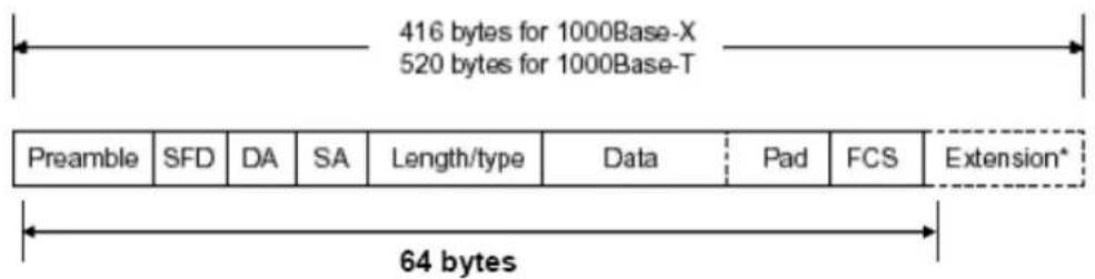
In the original 802.3 specification, Ethernet operates in half duplex only. Under this condition, when in 10Mbps LAN, it's 2500 meters, in 100Mbps LAN, it's approximately 200 meters and in 1000Mbps, 200 meters. According to the theory, it should be 20 meters. But it's not practical, so the LAN diameter is kept by using to increase the minimum frame size with a variable-length non-data extension bit field which is removed at the receiving MAC. The following tables are the frame format suitable for 10M, 100M and 1000M Ethernet, and some parameter values that shall be applied to all of these three types of Ethernet.
Actually, the practice Gigabit Ethernet chips do not feature this so far. They all have their chips supported full-duplex mode only, as well as all network vendors' devices. So this criterion should not exist at the present time and in the future. The switch's Gigabit module supports only full-duplex mode.
| Parameter value/LAN | 10Base | 100Base | 1000Base |
| Max. collision domain DTE to DTE | 100 meters | 100 meters for UTP | 100 meters for UTP |
| 412 meters for fiber | 316 meters for fiber | ||
| Max. collision domain with repeater | 2500 meters | 205 meters | 200 meters |
| Slot time | 512 bit times | 512 bit times | 512 bit times |
| Interframe Gap | 9.6us | 0.96us | 0.096us |
| AttemptLimit | 16 | 16 | 16 |
| BackoffLimit | 10 | 10 | 10 |
| JamSize | 32 bits | 32 bits | 32 bits |
| MaxFrameSize | 1518 | 1518 | 1518 |
| MinFrameSize | 64 | 64 | 64 |
| BurstLimit | Not applicable | Not applicable | 65536 bits |
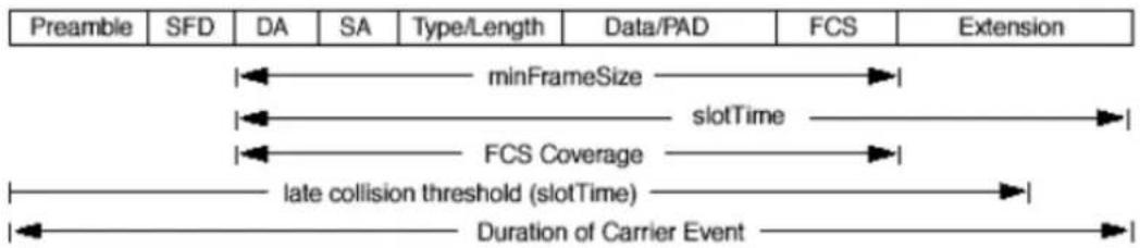
In full-duplex operation mode, both transmitting and receiving frames are processed simultaneously. This doubles the total bandwidth. Full duplex is much easier than half duplex because it does not involve media contention, collision, retransmission schedule, padding bits for short frame. The rest functions follow the specification of IEEE802.3. For example, it must meet the requirement of minimum inter-frame gap between successive frames and frame format the same as that in the half-duplex operation.
Because no collision will happen in full-duplex operation, for sure, there is no mechanism to tell all the involved devices. What will it be if receiving device is busy and a frame is coming at the same time? Can it use “backpressure” to tell the source device? A function flow control is introduced in the full-duplex operation.
2.3 Flow Control
Flow control is a mechanism to tell the source device stopping sending frame for a specified period of time designated by target device until the PAUSE time expires. This is accomplished by sending a PAUSE frame from target device to source device. When the target is not busy and the PAUSE time is expired, it will send another PAUSE frame with zero time-to-wait to source device. After the source device receives the PAUSE frame, it will again transmit frames immediately. PAUSE frame is identical in the form of the MAC frame with a pause-time value and with a special destination MAC address 01-80-C2-00-00-01. As per the specification, PAUSE operation can not be used to inhibit the transmission of MAC control frame.
Normally, in 10Mbps and 100Mbps Ethernet, only symmetric flow control is supported. However, some switches (e.g. 24-Port GbE Smart Lite Switch) support not only symmetric but asymmetric flow controls for the special application. In Gigabit Ethernet, both symmetric flow control and asymmetric flow control are supported. Asymmetric flow control only allows transmitting PAUSE frame in one way from one side, the other side is not but receipt-and-discard the flow control information. Symmetric flow control allows both two ports to transmit PASUE frames each other simultaneously.
Inter-frame Gap time
After the end of a transmission, if a network node is ready to transmit data out and if there is no carrier signal on the medium at that time, the device will wait for a period of time known as an inter-frame gap time to have the medium clear and stabilized as well as to have the jobs ready, such as adjusting buffer counter, updating counter and so on, in the receiver site. Once the inter-frame gap time expires after the de-assertion of carrier sense, the MAC transmits data. In IEEE802.3 specification, this is 96-bit time or more.
Collision
Collision happens only in half-duplex operation. When two or more network nodes transmit frames at approximately the same time, a collision always occurs and interferes with each other. This results the carrier signal distorted and undiscriminated. MAC can afford detecting, through the physical layer, the distortion of the carrier signal. When a collision is detected during a frame transmission, the transmission will not stop immediately but, instead, continues transmitting until the rest bits specified by jamSize are completely transmitted. This guarantees the duration of collision is enough to have all involved devices able to detect the collision. This is referred to as Jamming. After jamming pattern is sent, MAC stops transmitting the rest data queued in the buffer and waits for a random period of time, known as backoff time with the following formula. When backoff time expires, the device goes back to the state of attempting to transmit frame. The backoff time is determined by the formula below. When the times of collision is increased, the backoff time is getting long until the collision times excess 16. If this happens, the frame will be discarded and backoff time will also be reset.
$$ 0 \leq r < 2 ^ {k} $$
where
$$ k = \min (n, 1 0) $$
Frame Reception
In essence, the frame reception is the same in both operations of half duplex and full duplex, except that full-duplex operation uses two buffers to transmit and receive the frame independently. The receiving node always “listens” if there is traffic running over the medium when it is not receiving a frame. When a frame destined for the target device comes, the receiver of the target device begins receiving the bit stream, and looks for the PRE (Preamble) pattern and Start-of-Frame Delimiter (SFD) that indicates the next bit is the starting point of the MAC frame until all bit of the frame is received.
For a received frame, the MAC will check:
- If it is less than one slotTime in length, i.e. short packet, and if yes, it will be discarded by MAC because, by definition, the valid frame must be longer than the slotTime. If the length of the frame is less than one slotTime, it means there may be a collision happened somewhere or an interface malfunctioned in the LAN. When detecting the case, the MAC drops the packet and goes back to the ready state.
- If the DA of the received frame exactly matches the physical address that the receiving MAC owns or the multicast address designated to recognize. If not, discards it and the MAC passes the frame to its client and goes back to the ready state.
- If the frame is too long. If yes, throws it away and reports frame Too Long.
- If the FCS of the received frame is valid. If not, for 10M and 100M Ethernet, discards the frame. For Gigabit Ethernet or higher speed Ethernet, MAC has to check one more field, i.e. extra bit field, if FCS is invalid. If there is any extra bits existed, which must meet the specification of IEEE802.3. When both FCS and extra bits are valid, the received frame will be accepted, otherwise discards the received frame and reports frameCheckError if no extra bits appended or alignmentError if extra bits appended.
- If the length/type is valid. If not, discards the packet and reports lengthError.
- If all five procedures above are ok, then the MAC treats the frame as good and de-assembles the frame.
What if a VLAN tagging is applied?
VLAN tagging is a 4-byte long data immediately following the MAC source address. When tagged VLAN is applied, the Ethernet frame structure will have a little change shown as follows.
| Pre | SFD | DA | SA | VLAN type ID | Tag control information | Length/ type | Data | Pad | FCS | Ext |
Only two fields, VLAN ID and Tag control information are different in comparison with the basic Ethernet frame. The rest fields are the same.
The first two bytes is VLAN type ID with the value of 0x8100 indicating the received frame is tagged VLAN and the next two bytes are Tag Control Information (TCI) used to provide user priority and VLAN ID, which are explained respectively in the following table.
| Bits 15-13 | User Priority 7-0, 0 is lowest priority |
| Bit 12 | CFI (Canonical Format Indicator)1: RIF field is present in the tag header0: No RIF field is present |
| Bits 11-0 | VID (VLAN Identifier)0x000: Null VID. No VID is present and only user priority is present.0x001: Default VID0xFFFF: Reserved |
Note: RIF is used in Token Ring network to provide source routing and comprises two fields, Routing Control and Route Descriptor.
When MAC parses the received frame and finds a reserved special value 0x8100 at the location of the Length/Type field of the normal non-VLAN frame, it will interpret the received frame as a tagged VLAN frame. If this happens in a switch, the MAC will forward it, according to its priority and egress rule, to all the ports that is associated with that VID. If it happens in a network interface card, MAC will deprive of the tag header and process it in the same way as a basic normal frame. For a VLAN-enabled LAN, all involved devices must be equipped with VLAN optional function.
At operating speeds above 100 Mbps, the slotTime employed at slower speeds is inadequate to accommodate network topologies of the desired physical extent. Carrier Extension provides a means by which the slotTime can be increased to a sufficient value for the desired topologies, without increasing the minFrameSize parameter, as this would have deleterious effects. Nondata bits, referred to as extension bits, are appended to frames that are less than slotTime bits in length so that the resulting transmission is at least one slotTime in duration. Carrier Extension can be performed only if the underlying physical layer is capable of sending and receiving symbols that are readily distinguished from data symbols, as is the case in most physical layers that use a block encoding/decoding scheme.
The maximum length of the extension is equal to the quantity (slotTime - minFrameSize). The MAC continues to monitor the medium for collisions while it is transmitting extension bits, and it will treat any collision that occurs after the threshold (slotTime) as a late collision.
Chapter 3: Operation of Web-based Management
This chapter would introduce how to manage your Smart Lite Switch and how to configure the 10/100/1000Mbps TP Ports on the switch via web user interfaces. Smart Lite Switch provides 8 fixed Gigabit Ethernet TP ports. With this facility, you can easily access and monitor the status like MIBs, port activity, and multicast traffic through any ports on the switch.
The default values of the Switch are listed in the figure below:
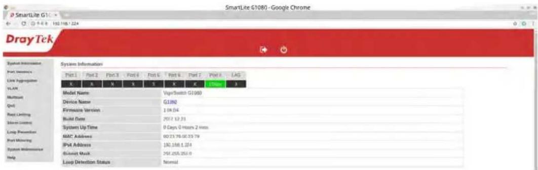
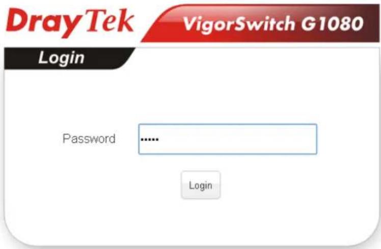
When the configuration of your Smart Lite Switch is finished, you can browse it by the IP address you set up. For instance, uncheck the Enable box of DHCP Setting first (it is enabled in default) on System Maintenance. Next, type http://192.168.1. in the address row in a browser, then the following screen would show up and ask for your password input for login and access authentication. The default password is “admin”. For the first time access, please enter the default password, and click
Smart Lite Switch supports a simplified user management function which allows only one administrator to configure the switch at one time.
To optimize the display effect, we recommend Microsoft IE and 1024x768 display resolution.
3.1 Web Management Home Overview
After login, System Information would be displayed as the following illustration. This page lists default values and shows you the basic information of the switch, including “Model Name”, “Device Name”, “Firmware Version”, “Build Date”, “MAC Address”, “IPv4 Address”, “Subnet Mask”, and “Loop Detection Status”. With this information, you will know the software version, MAC address, ports available and so on. It would be helpful while malfunction occurred.
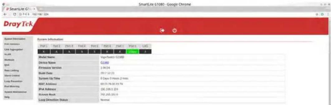
On the left side, the main menu tree for web is listed in the page. The functions of each folder are described in its corresponded section respectively. As to the function names in normal type are the sub-functions. When clicking it, the function is performed.
3.2 System Information
Function name:
System Information
Function description:
System Information shows Model Name", "Device Name", "Firmware Version", "Build Date", "MAC Address", "IPv4 Address", "Subnet Mask", and "Loop Detection Status".
System Information
| Port 1 | Port 2 | Port 3 | Port 4 | Port 5 | Port 6 | Port 7 | Port 8 | LAG |
| X | X | X | X | X | X | X | 1G00e | X |
| Model Name | VigorSwitch G1080 | |||||||
| Device Name | G1080 | |||||||
| Firmware Version | 1.04.04 | |||||||
| Build Date | 2017.12.21 | |||||||
| System Up Time | 0 Days 0 Hours 2 max | |||||||
| MAC Address | 00:23:79:00:23:79 | |||||||
| IPv4 Address | 192.168.1.224 | |||||||
| Subnet Mask | 265,255.255.0 | |||||||
| Loop Detection Status | Normal | |||||||
Parameter description:
| Port 1 ~ Port 8 | Display the connection status for each physical port. If connected, transmission rate will be shown below the port. |
| Model Name | Display the model name of the switch. |
| Device Name | Display the device name of such VigorSwitch. Click the link to modify the device name if required. |
| Firmware Version | Display the firmware version in this switch. |
| Build Date | Display the date of the firmware released. |
| MAC address | It is the Ethernet MAC address of the management agent in this switch. |
| IPv4 address | The IPv4 address of the switch. |
| Subnet Mask | The subnet mask of the switch. |
| Loop Detection Status | Normal: If loop detection is enabled and the switch does not detect a loop or the function disabled. Loop: If loop detection is enabled and the switch detects a loop. |
3.3 Port Statistics
Function name:
Port Statistics
Function description:
Display information, including link status, number of transmission packets and number of receiving packets for each physical port.
Port Statistics
| Port | Link Status | Num. of Tx Packets | Num. of Rx Packets |
| 1 | 1000 Mbps | 1723 | 962 |
| 2 | Down | 0 | 0 |
| 3 | Down | 0 | 0 |
| 4 | Down | 0 | 0 |
| 5 | Down | 0 | 0 |
| 6 | Down | 0 | 0 |
| 7 | Down | 0 | 0 |
| 8 | Down | 0 | 0 |
| 9 | Down | 0 | 0 |
| 10 | Down | 0 | 0 |
Clear Counters
Parameter description:
| Link Status | Display if the connection for such port is up (with the transmission rate) or down. |
| Num. of Tx Packets | Display the total number of outgoing packets transmitted through such port. |
| Num. of Rx Packets | Display the total number of incoming packets through such port. |
| Clear Counters | Remove all the statistics on this page. |
3.4 Link Aggregation
Function name:
Link Aggregation
Function description:
This page allows a user to configure Link Aggregation Group.
Link Aggregation
| Link Aggregation Mode | Disable | LACP | ||
| LACP mode | Passive | Passive | ||
| Link Aggregation Group 1 | Active | |||
| Link Group Status | Port 7 | Port 8 | Port 9 | Port 10 |
| Link Disconnected | Link Disconnected | Link Disconnected | Link Disconnected | |
Parameter description:
| Link Aggregation Mode | The type of the LAG.Disable: LAG function is disabled.LACP: The groups of ports assigned to dynamic LAG are candidate ports. LACP determines which candidate ports are active member ports. |
| LACP mode | Passive: Inactive member port.Active: Active member port. |
| Link Group Status | Display LAG port link status. |
3.5 VLAN
Function name:
VLAN
Function description:
This page allows a user to configure VLAN Interface related settings.

VLAN List
Number of available VLAN ID left: 7 VID(s)
Create New VLAN

Click on corresponding cell in above table to toggle VLAN tagging member state.
Parameter description:
| PVID | A PVID (Port VLAN ID) is a tag that adds to incoming untagged frames received on a port so that the frames are forwarded to the VLAN group that the tag defines. |
| Apply PVID | Click it to modify the PVID settings. |
| VLAN List | Display available VLAN IDs. |
| Create New VLAN | Click it to create a new VLAN ID. |
| Modify | Click it to change VLAN ID number. 802.1Q Tag-based page will appear for you to tagged or untagged members (physical ports)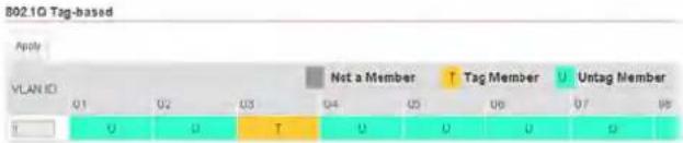 Click on box to change member stateif Trunkang enable,Please verify VLAN configurations in trunk portTag Member: Specify the port is tagged in the VLAN.Untag Member Specify the port is untagged in the VLAN. Click on box to change member stateif Trunkang enable,Please verify VLAN configurations in trunk portTag Member: Specify the port is tagged in the VLAN.Untag Member Specify the port is untagged in the VLAN. |
| Delete | Remove user-defined VLAN ID. |
3.6 Multicast
Function name:
Multicast
Function description:
This page allows a user to block unknown multicast and enable/disable IGMP snooping.
Multicast
| Blocking Unknown Multicast | Enable |
| Enable IGMP Snooping | Disable |
| Apply |
Block Unknown Multicast without IGMP snooping.
Blocking unknown multicast with IGMP snooping disabled will resulted in dropping all multicast packets, meaning no multicast at all. If you wish to let multicast packets pass this switch without IGMP, please disable "Block Unknown Multicast".
IGMP Snooping Status
Multicast Group Port VLAN
| Parameter description: | |
| Blocking Unknown Multicast | Enable: Drop all multicast packets. Disable: Let all multicast packets pass through this switch. |
| Enable IGMP Snooping | Enable: Block multicast packets. Disable: Drop all multicast packets. |
| IGMP Snooping Status | Display the name of multicast group, related port number and VLAN ID that applied with IGMP snooping. |
3.7 QoS
Function name:
QoS
Function description:
This page allows users to configure settings for QoS.
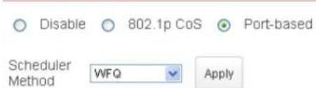
QoS Operation Mode
| Port | 1 | 2 | 3 | 4 | 5 | 6 | 7 | 8 | 9 | 10 | weight |
| Low Priority Queue | 1 | ||||||||||
| Normal Priority Queue | 2 | ||||||||||
| Medium Priority Queue | 4 | ||||||||||
| High Priority Queue | 8 |
Parameter description:
| Disable | Disable the QoS function for LAN ports. |
| 802.1p CoS | Apply 802.1p CoS for each LAN port. |
| Port-based | QoS settings would apply to specified LAN port only. |
| Scheduler Method | WFQ: Weighted fair queueing (WFQ) is an algorithm for data packet scheduling. Such mechanism can specify, for each flow, which fraction of the capacity will be given.Strict Priority: Strict Priority (SP) can ensure service for high-priority traffic. The software assigns the maximum weights to each queue, to cause the queuing mechanism to serve as many packets in one queue as possible before moving to a lower queue. This method biases the queuing mechanism to favor the higher queues over the lower queues.For example, strict queuing processes as many packets as possible in qosp3 before processing any packets in qosp2, then processes as many packets as possible in qosp2 before processing any packets in qosp1, and so on. |
| Apply | Save the settings or changes to the switch. |
| Port | The sequence of packets passing through LAN port(s) will be processed according to the queue setting (listed below) configured in this page.Low Priority QueueNormal Priority QueueMedium Priority QueueHigh Priority QueueIn which, packets transmitted via LAN Port with HighPriority queue will be processed with high priority. |
| 1 ~ 10 | 1~10 means LAN port 1 ~ LAN port 10 of VigorSwitch. |
| Weight | Bandwidth for each queue (low priority queue to high priority queue) is dispatched according to the weight value. Use the drop down menu to select weight value for each queue. |
3.8 Rate Limiting
Function name:
Rate Limiting
Function description:
This page allows users to configure ingress port rate limit and egress port rate limit. The ingress rate limit is the number of bits per second that can be received from the ingress interface. Excess bandwidth above this limit is discarded.
Rate Limiting
| Port | Ingress rate | Egress rate |
| 1 | Unlimited | Unlimited |
| 2 | Unlimited | Unlimited |
| 3 | Unlimited | Unlimited |
| 4 | Unlimited | 512Kbps1Mbps2Mbps4Mbps8Mbps16Mbps32Mbps64Mbps128Mbps256Mbps512Mbps |
| 5 | Unlimited | |
| 6 | Unlimited | |
| 7 | Unlimited | |
| 8 | Unlimited | |
| 9 | Unlimited | |
| 10 | Unlimited | Unlimited |
Apply
Parameter description:
| Port | Display the port number. |
| Ingress rate | Unlimited: There is no limitation for ingress port.512kbps ~ 512Mbps: Select the rate value for ingress bandwidth control. |
| Egress rate | Unlimited: There is no limitation for egress port.512kbps ~ 512Mbps: Select the rate value for egress bandwidth control. |
| Apply | Save the settings or changes to the switch. |
3.9 Storm Control
Function name:
Storm Control
Function description:
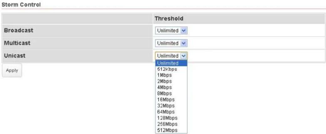
Configure the storm control rate for packets.
| Parameter description: | |
| Broadcast | Unlimited: There is no limitation for storm control rate for unknown broadcast packet.512kbps ~ 512Mbps: Select the storm control rate for unknown broadcast packet. |
| Multicast | Unlimited: There is no limitation for storm control rate for unknown multicast packet.512kbps ~ 512Mbps: Select the storm control rate for unknown multicast packet. |
| Unicast | Unlimited: There is no limitation for storm control rate for unknown unicast packet.512kbps ~ 512Mbps: Select the storm control rate for unknown unicast packet. |
| Apply | Save the settings or changes to the switch. |
3.10 Loop Prevention
Function name:
Loop Prevention
Function description:
Switch will send out looping detection frame to detect the ports on the switch whether they have looping traffic happen.
Loop Prevention

| Parameter description: | |
| Loop Control | Set the port loop detection.Off: Disable the function of loop control.Loop Detection Only: VigorSwitch will shut down a port automatically when it detects a loop on that port. However, the detected port will be active again if the loop disappears.Loop Detection&Prevention: VigorSwitch will shut down a port automatically when it detects a loop on that port. |
| Apply | Save the settings or changes to the switch. |
3.11 Port Mirroring
Function name:
Port Mirroring
Function description:
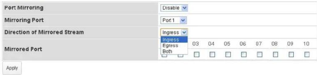
Display mirroring port and mirrored port web page for detailed configuration.
Port Mirroring
Parameter description:
| Port Mirroring | Select mirror session state. Disable: Disable mirror. Enable: Enable port-based mirror. |
| Mirroring Port | Port1 to Port10: Select a mirroring port by using the drop down list. |
| Direction of Mirrored Stream | Ingress: Select source RX ports to be mirrored. Egress: Select source TX ports to be mirrored. Both: Select source TX ports and RX ports to be mirrored. |
| Mirrored Port | Select mirror session monitor port. Whether normal packet could be sent or received by mirrored port. |
| Apply | Save the settings or changes to the switch. |
3.12 System Maintenance
Function name:
System Maintenance
Function description:
Management IP address
| DHCP | Disable |
| IP Address | 192.168.110 |
| Subnet Mask | 255.255.255.0 |
Apply IP address
Management Password
| New Password | |
| Reconfirm New Password |
Apply password change
Device Configuration
| Management IP Address | |
| DHCP | Enable: Activate DHCP client of VigorSwitch. Disable: Disable DHCP client of VigorSwitch. |
| IP Address | Enter the IP address of VigorSwitch. |
| Subnet Mask | Enter the subnet mask of VigorSwitch. |
| Apply IP address | Save the modification of IP address and subnet mask. |
| Management Password | |
| New Password | Enter the password for new account. |
| Reconfirm New Password | Retype password to make sure the password is exactly you typed before in “Password” field. |
| Apply password change | Save the modification of password setting. |
| Device Configuration | |
| Restore | Restore the previously stored configuration file and apply to such device. |
| Backup | Store the configuration for such device as a file. |
| Firmware Upgrade | |
| Enter Upgrade Mode | Click it to open the following page. Specify the new firmware and click Upgrade. Specify the new firmware and click Upgrade. |
| Reboot or Reset | |
| Reset | Return to factory default settings. |
| Reboot | Reboot Vigor router with current settings. |
Chapter 4: Trouble Shooting
4.1 Resolving No Link Condition
The possible causes for a no link LED status are as follows:
● The attached device is not powered on
● The cable may not be the correct type or is faulty
● The installed building premise cable is faulty
● The port may be faulty
4.2 Q & A
Q1.How to configure the switch to support loop detection:
Answer:
Vigor switch support loop detection in default. If you want to disable loop detection, you can simply set STP --> STP Global Setting --> Global Setting --> BPDU Forward --> flooding to filter.
Q2. Where is Rapid Spanning Tree, Where can I find it?
Answer:
RSTP equals to Rapid Spanning Tree. Please follow the following direction to choose it: STP --> STP Global Setting --> Global Setting --> Force Version --> RSTP.
- Smart Lite Gigabit Switch
- User's Guide
- VigorSwitch G1080 Smart Lite Giga Switch User's Guide
- Intellectual Property Rights (IPR) Information
- Copyrights
- Trademarks
- Caution and Electronic Emission Notices
- Caution
- Warranty
- Be a Registered Owner
- Firmware & Tools Updates
- Table of Contents
- Chapter 1: Introduction....1
- Chapter 2: Basic Concept and Management....13
- Chapter 3: Operation of Web-based Management....23
- Chapter 4: Trouble Shooting....37
- Chapter 1: Introduction
- Overview
- QoS
- VLAN
- Port Trunking
- Features
- Hardware
- Management
- Packing List
- LED Indicators and Connectors
- Hardware Installation
- Desktop Installation
- Installing Network Cables
- Configuring the Management Agent of Switch
- Managing VigorSwitch G1080 through Ethernet Port
- IP Address Assignment
- IP address:
- Class A:
- Class B:
- Class C:
- Class D and E:
- Subnet mask:
- -
- Default gateway:
- Typical Applications
- Chapter 2: Basic Concept and Management
- What's the Ethernet
- Logical Link Control (LLC)
- Media Access Control (MAC)
- MAC Addressing
- Ethernet Frame Format
- How does a MAC work?
- Frame transmission
- Flow Control
- Inter-frame Gap time
- Collision
- Frame Reception
- What if a VLAN tagging is applied?
- Chapter 3: Operation of Web-based Management
- Web Management Home Overview
- System Information
- Function name:
- Function description:
- Port Statistics
- Link Aggregation
- VLAN
- Multicast
- QoS
- Rate Limiting
- Storm Control
- Loop Prevention
- Port Mirroring
- System Maintenance
- Chapter 4: Trouble Shooting
- Resolving No Link Condition
- Q & A
- Q1.How to configure the switch to support loop detection:
- Q2. Where is Rapid Spanning Tree, Where can I find it?
Brand : Draytek
Model : VigorSwitch G1080
Category : Switch