
ES 2160 - Mixing console RCF - Free user manual and instructions
Find the device manual for free ES 2160 RCF in PDF.


| Product Type | Mixer Amplifier |
| Model | ES 2160 |
| Power Output (@ 4Ω) | 160 W RMS |
| Power Output (@ 100V line) | 160 W RMS |
| Frequency Response | 50 Hz - 14 kHz (-3 dB) |
| Total Harmonic Distortion (THD+N) | < 0.3% @ 1 kHz nominal power |
| Total Inputs | 8 (7 balanced, 2 unbalanced, 7 mono, 2 stereo) |
| Mic/Line Inputs | 4 (Euroblock, XLR, with phantom power 32 V DC) |
| Line Inputs | 2 (RCA) |
| Paging Inputs | 2 (RJ45 for RCF BM 3001 microphone) |
| Signal Outputs | 2 (RCA: PRE OUT and MUSIC ON HOLD) |
| Speaker Output Connector | Euroblock (4Ω, 70V, 100V) |
| Tone Controls | Bass and Treble (for MP3 and AUX), Presence control (for inputs 1-4) |
| High-Pass Filter | 150 Hz, switchable per input |
| Priority System | Yes (VOX, graduated/interlocked, chime) |
| Music on Hold Output | Yes (RCA, sends MP3 signal regardless of volume) |
| Audio Sources | MP3 player (USB, SD, Bluetooth, AUX jack) |
| Bluetooth | Yes (A2DP, with antenna) |
| Operating Voltage | 220-240 V or 115 V (selectable internally), 50/60 Hz |
| Power Consumption | 350 W |
| Dimensions (W x D x H) | 442 x 230 x 88 mm (17.4 x 9.06 x 3.46 in) |
| Weight | 5.4 kg (11.9 lbs) |
| Rack Mountable | Yes, 19", 2U |
| Protections | Short circuit, thermal, DC, fuse |
| Cooling | Convection |
Frequently Asked Questions - ES 2160 RCF
User questions about ES 2160 RCF
0 question about this device. Answer the ones you know or ask your own.
Ask a new question about this device
Download the instructions for your Mixing console in PDF format for free! Find your manual ES 2160 - RCF and take your electronic device back in hand. On this page are published all the documents necessary for the use of your device. ES 2160 by RCF.
USER MANUAL ES 2160 RCF
SAFETY PRECAUTIONS AND GENERAL INFORMATION....4
DESCRIPTION 6
FRONT PANEL 7
REAR PANEL 8
MP3 PLAYER 11
AMPLIFIER OPERATION....14
SPEAKERS CONNECTION....16
POWER SUPPLY VOLTAGE CHANGE 17
ITALIANO
AVVERTENZE PER LA SICUREZZA 18
DESCRIZIONE 21
PANNELLO FRONTALE 22
PANNELLO POSTERIORE 23
LETTORE MP3 26
SAFETY PRECAUTIONS AND GENERAL INFORMATION
The symbols used in this document give notice of important operating instructions and warnings which must be strictly followed.
 | CAUTION | Important operating instructions: explains hazards that could damage a product, including data loss. |
 | WARNING | Important advice concerning the use of dangerous voltages and the potential risk of electric shock, personal injury or death. |
 | IMPORTANT NOTES | Helpful and relevant information about the topic. |
 | SUPPORTS, TROLLEYS AND CARTS | Information about the use of supports, trolleys and carts.Reminds to move with extreme caution and never tilt. |
 | WASTE DISPOSAL | This symbol indicates that this product should not be disposed with your household waste, according to the WEEE directive (2012/19/EU) and your national law. |

IMPORTANT NOTES
This manual contains important information about the correct and safe use of the device. Before connecting and using this product, please read this instruction manual carefully and keep it on hand for future reference. The manual is to be considered an integral part of this product and must accompany it when it changes ownership as a reference for correct installation and use as well as for the safety precautions. RCF S.p.A. will not assume any responsibility for the incorrect installation and / or use of this product.
SAFETY PRECAUTIONS
- All the precautions, in particular the safety ones, must be read with special attention, as they provide important information.
- Power supply from mains
a. The mains voltage is sufficiently high to involve a risk of electrocution; install and connect this product before plugging it in.
b. Before powering up, make sure that all the connections have been made correctly and the voltage of your mains corresponds to the voltage shown on the rating plate on the unit, if not, please contact your RCF dealer.
c. The metallic parts of the unit are earthed through the power cable. An apparatus with CLASS I construction shall be connected to a mains socket outlet with a protective earthing connection.
d. Protect the power cable from damage; make sure it is positioned in a way that it cannot be stepped on or crushed by objects.
e. To prevent the risk of electric shock, never open this product: there are no parts inside that the user needs to access.
f. Be careful: in the case of a product supplied by manufacturer only with POWERCON connectors and without a power cord, jointly to POWERCON connectors type NAC3FCA (power-in) and NAC3FCB (power-out), the following power cords compliant to national standard shall be used:
- EU: cord type H05VV-F 3G 3x2.5 mm2 - Standard IEC 60227-1
- JP: cord type VCTF 3x2 mm2; 15Amp/120V\~ - Standard JIS C3306
-
US: cord type SJT/SJTO 3x14 AWG; 15Amp/125V\~ - Standard ANSI/UL 62
-
Make sure that no objects or liquids can get into this product, as this may cause a short circuit. This apparatus shall not be exposed to dripping or splashing. No objects filled with liquid, such as vases, shall be placed on this apparatus. No naked sources (such as lighted candles) should be placed on this apparatus.
-
Never attempt to carry out any operations, modifications or repairs that are not expressly described in this manual. Contact your authorized service centre or qualified personnel should any of the following occur:
-
The product does not function (or functions in an anomalous way).
- The power cable has been damaged.
- Objects or liquids have got in the unit.
-
The product has been subject to a heavy impact.
-
If this product is not used for a long period, disconnect the power cable.
- If this product begins emitting any strange odours or smoke, switch it off immediately and disconnect the power cable.
- Do not connect this product to any equipment or accessories not foreseen.
For suspended installation, only use the dedicated anchoring points and do not try to hang this product by using elements that are unsuitable or not specific for this purpose. Also check the suitability of the support surface to which the product is anchored (wall, ceiling, structure, etc.), and the components used for attachment (screw anchors, screws, brackets not supplied by RCF etc.), which must guarantee the security of the system / installation over time, also considering, for example, the mechanical vibrations normally generated by transducers. To prevent the risk of falling equipment, do not stack multiple units of this product unless this possibility is specified in the user manual.
-
RCF S.p.A. strongly recommends this product is only installed by professional qualified installers (or specialised firms) who can ensure correct installation and certify it according to the regulations in force. The entire audio system must comply with the current standards and regulations regarding electrical systems.
-
Supports, trolleys and carts.

The equipment should be only used on supports, trolleys and carts, where necessary, that are recommended by the manufacturer. The equipment / support / trolley / cart assembly must be moved with extreme caution. Sudden stops, excessive pushing force and uneven floors may cause the assembly to overturn. Never tilt the assembly.
-
There are numerous mechanical and electrical factors to be considered when installing a professional audio system (in addition to those which are strictly acoustic, such as sound pressure, angles of coverage, frequency response, etc.).
-
Hearing loss. Exposure to high sound levels can cause permanent hearing loss. The acoustic pressure level that leads to hearing loss is different from person to person and depends on the duration of exposure. To prevent potentially dangerous exposure to high levels of acoustic pressure, anyone who is exposed to these levels should use adequate protection devices. When a transducer capable of producing high sound levels is being used, it is therefore necessary to wear ear plugs or protective earphones. See the manual technical specifications to know the maximum sound pressure level.
OPERATING PRECAUTIONS
- Place this product far from any heat sources and always ensure an adequate air circulation around it.
- Do not overload this product for a long time.
- Never force the control elements (keys, knobs,etc.).
- Do not use solvents, alcohol, benzene or other volatile substances for cleaning the external parts of this product.

IMPORTANT NOTES
To prevent the occurrence of noise on line signal cables, use screened cables only and avoid putting them close to:
- Equipment that produces high-intensity electromagnetic fields
- Power cables
- Loudspeaker lines


WARNING! CAUTION! To prevent or electric shock, never expose this or humidity.

WARNING! To prevent electric shock do not connect to mains power supply illle is removed.

WARNING! to reduce the risk of electric to not disassemble this product unless you lifted. Refer servicing to qualified service el.
CORRECT DISPOSAL OF THIS PRODUCT

This product should be handed over to an authorized collection site for recycling waste electrical and electronic equipment (EEE). Improper handling of this type of waste could have a possible negative impact on the environment and human health due to potentially hazardous substances that are generally associated with EEE. At the same time, your cooperation in the correct disposal of this product will contribute to the effective usage of natural resources. For more information about where you can drop off your waste equipment for recycling, please contact your local city office, waste authority or your household waste disposal service.
CARE AND MAINTENANCE
To ensure a long-life service, this product should be used following these advices:
- If the product is intended to be set up outdoors, be sure it is under cover and protected to rain and moisture.
- If the product needs to be used in a cold environment, slowly warm up the voice coils by sending a low-level signal for about 15 minutes before sending high-power signals.
- Always use a dry cloth to clean the exterior surfaces of the speaker and always do it when the power is turned off.

CAUTION: to avoid damaging the exterior do not use cleaning solvents or abrasives.


WARNING! CAUTION! For powered leaning only when the power is
DESCRIPTION
ES 2160 is a 160 W mixer-amplifier, with 4 mic-line audio inputs on removable connectors (the first input has also an XLR socket), an MP3 player with Bluetooth and an aux input for a music source (i.e. CD players, tuners, etc.).
Input 1 has a signal detection circuit ('VOX') providing automatic priority operation.
All inputs 1, 2, 3 and 4 can access the priority through an external command (connected to the removable connector). Inputs 2 and 3 also have an RJ 45 socket for quick connection of a single RCF BM 3001 paging microphone (through CAT5 cable).
The amplifier output is available either for low impedance speakers (min. 4 Ω) or 100 – 70 V constant voltage line (for speakers having 100 – 70 V transformers).
The MUSIC ON HOLD output directly sends the internal MP3 player signal to additional amplifiers, mixers, phone systems ('music on hold' function), etc. .
The PRE OUT output sends the signal (the same mix routed to the internal amplifier) to additional amplifiers.
The 4 mic.-line inputs have a common PRESENCE control and separate high-pass filters that are useful for improving speech intelligibility.
The internal MP3 player and the AUX INPUT have common tone controls.
Front panel LEDs indicate the device state (ON, PROT), priority circuit enabled (PRIOR) and the signal level / peak (SIG/PK).
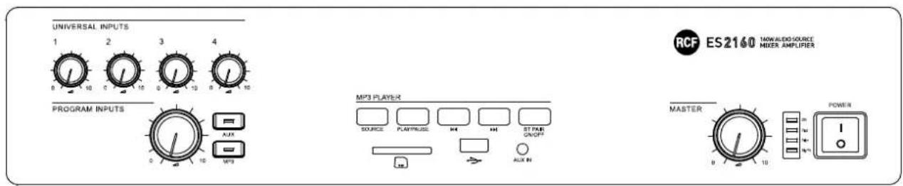
FRONT PANEL
![UNIVERSAL INPUTS 1 2 3 4 0 10 0 10 0 10 0 10 [1] PROGRAM INPUTS 0 -1 -2 -3 -4 AUX MP3 MP3 PLAYER SOURCE PLAY/PULSE H4 H4 ST PAR ON/OF RUN IN MASTER 0 10 0 10 0 10 0 10 POWER [5] [6] [7] RCF ES2160 NOW ALDI SOURCE MIXER AMPLIFIER](/content/2026/05/897778/images/dbf62e9da223633c9cb81c1303e38700c73c84ce1d347bc1be17ed58cc3547d8.jpg)
[1] Volume controls for each universal input (1, 2, 3, 4).
Note: unused input volume controls should always be turned fully counter clockwise (to 0).
[2] MP3 PLAYER [8] and AUX INPUT [14] volume control.
[3] AUX button (with LED). Press to turn on (the LED is lit) the AUX INPUT [14] (on the rear panel), which signal is sent to the internal amplifier (and also PRE OUT [18]). If activated, the internal MP3 player will be muted (the MP3 button LED will turn off).
[4] MP3 button (with LED). Press to turn on (the LED is lit) the MP3 player, which signal is sent to the internal amplifier (and also MUSIC ON HOLD [19] and PRE OUT [18] outputs). If activated, the AUX INPUT [14] on the rear panel will be muted (the AUX button LED will turn off).
The MP3 player signal is always sent to the MUSIC ON HOLD [19] output (that is not affected by the volume control and MP3 / AUX buttons).
[5] Internal amplifier MASTER volume control. Note: the audio outputs having RCA connectors (MUSIC ON HOLD [19] and PRE OUT [18]) are not affected by the MASTER volume control.
[6] LEDs
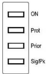
| ON | Green the device is switched on. | |
| Prot | Red overload protection | |
| Orange thermal protection | ||
| Prior | Yellow | priority by either VOX function or an universal input or SEQ. CHIME CMD |
| Sig/Pk | Green the signal level is higher than - 15 dB | |
| Green + Red the signal level is in the 0 ÷ +2 dB range | ||
| Red (peak) the signal level is equal or higher than +3 dB | ||
0 dB = signal level that allows to get the amplifier maximum power.
The internal 'limiter' circuit helps to avoid the amplifier overloading, yet it is advisable to reduce the MASTER volume (or a single input volume where a too high signal is present) when the SIG/PK LED is continuously indicating red.
[7] Main POWER switch (0 = off; 1 = on)
[8] MP3 PLAYER with Bluetooth (see the respective manual section).
REAR PANEL
![WARNING: [19] 350V/540V, 700 V RISK OF ELE CAUTION: H RISK OF ELE RISK OF ELE RISK OF ELE RISK OF ELE RISK OF ELE RISK OF ELE RISK OF ELE RISK OF ELE RISK OF ELE RISK OF ELE RISK OF ELE RISK OF ELE RISK OF ELE RISK OF ELE RISK OF ELE RISK OF ELE RISK OF ELE RISKOF ELE RISK OF ELE RISK OF ELE RISK OF ELE RISK OF ELE RISK OF ELE RISK OF ELE RISK OF ELE RISK OF ELE RISK OF ELE RISK OF ELE RISK OF ELE RISK OF ELE RISK OF ELE RISK OF ELE RISK OF ELE RISK OF ELE [25] [24] [26] [23] [21] [22] [20] [10] [9] [19] [18] [14] [15] [16] [17] [13] [12] [11] [13] [12] [11] [10] [9] [8] [7] [6] [5] [4] [3] [2] [1] [0]](/content/2026/05/897778/images/057e94ae40d495ce00620b7432ec92d54f7e8fdbdc6892b5f0249e359a58f3a7.jpg)
[9] Four balanced audio inputs (1, 2, 3, 4) with sockets for removable connectors.
[10] Each input has 4 dip-switches:
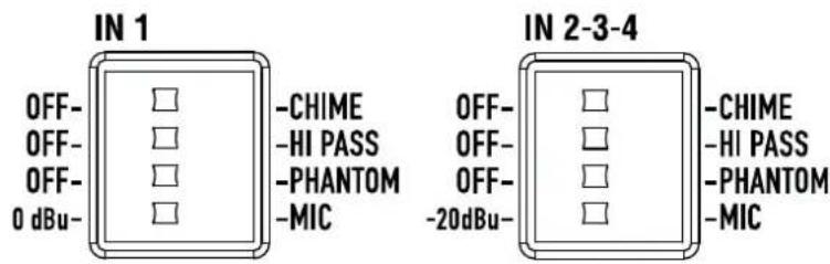
| 1 | OFF - CHIME | OFF: the chime is disabled. | CHIME: the chime will be played as soon as a priority command is activated. |
| 2 | OFF - HI PASS | OFF: the audio hi-pass filter is not inserted (flat frequency response). | HI PASS: the audio hi-pass filter is inserted. |
| 3 | OFF - PHANTOM | OFF: the PHANTOM power supply is not available on the respective audio input. | PHANTOM: the PHANTOM power supply is available on the respective audio input. |
| 4 | IN 10 dBu - MICIN 2, 3, 4-20 dBu - MIC | 0 dBu: input level = 0 dBu (775 mV). MIC: microphone audio input. | |
| -20 dBu: input level = -20 dBu (78 mV). MIC: microphone audio input. |
Examples of dip-switches 3 and 4 settings:
| DIP 3 DIP | 4 MODE USE | (EXAMPLES) | |
| OFF 0 dBu | 0 dBu (IN 1) | CD/MP3 players, tuners, message players, phone systems | |
| PHANTOM 0 dBu | 0 dBu + PHANTOM (IN 1) | Pre-amplified (0 dBu output) paging microphone that needs 'phantom' power supply | |
| OFF -20 dBu | -20 dBu (IN 2, 3, 4) | Audio source having a – 20 dBu output | |
| PHANTOM -20 dBu | -20 dBu | + PHANTOM (IN 2, 3, 4) BM 3001 paging microphone | |
| OFF MIC | MIC | Dynamic microphones | |
| PHANTOM | MIC MIC | + PHANTOM Electret microphones | |
When a BM 3001 paging microphone is connected, it is necessary to choose the '-20 dBu + PHANTOM' mode in the respective input (dip-switch no.3 set to PHANTOM; dip-switch no.4 set to -20 dBu).
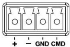
[11] Channel no.1 XLR input
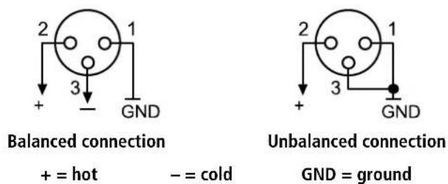
$$ + = \text { hot } $$
$$ - = \text { cold } $$
$$ \mathrm{GND} = \text { g r o u n d } $$
Do NOT use an unbalanced connection when the 'Phantom' power supply is switched on.
[12] PRESENCE CONTROL (f = 2.15 kHz) common for all the inputs 1, 2, 3, 4.
[13] Two RJ 45 sockets (inputs 2 and 3) to connect a single RCF BM 3001 paging microphone.
Note: when a BM 3001 paging microphone is connected, it is necessary to set the dip-switches 3 and 4 of the respective input to the -20 dBu + PHANTOM mode (see [10]).
[14] AUX INPUT with dual RCA connector.
The two channels of the stereo source connected to the AUX INPUT are mixed internally (to get a mono signal).
[15] GAIN AUX: AUX INPUT gain control.
[16] GAIN MP3: MP3 player gain control.
[17] TREBLE and BASS controls for both the internal MP3 player and the AUX INPUT.
[18] PRE OUT audio output (with RCA connector) that sends the same signal routed to the internal amplifier (signal that can be either a single source with priority or the mix of all the four inputs and either the internal MP3 player or the AUX INPUT).
Use PRE OUT to connect additional external amplifiers.
[19] MUSIC ON HOLD audio output (with RCA connector) that sends the internal MP3 audio signal (mono).
The MUSIC ON HOLD output is not affected by any volume control, nor a switch, and can be linked to a telephone system (in order to get the 'Music On Hold' function).
[20] 8 dip-switches PRESET to set the priority options:
| 1 | MIX – MUSIC OFF | MIX: the MP3 player or the AUX INPUT is always present in the mix sent to the amplifier, even during a priority command. | MUSIC OFF: the MP3 player or the AUX INPUT is not sent to the amplifier during a priority command. |
| 2 | PR. IN1 – PR. IN2 | PR. IN1: the input 1 has the highest priority level with override (but the SEQUENTIAL CHIME CMD.) through the relevant command (or VOX), if the dip-switch no.3 has been set to 'graduated priority'. | PR. IN2: the input 2 has the highest priority level with override (but the SEQUENTIAL CHIME CMD.) through the relevant command, if the dip-switch no.3 has been set to 'graduated priority'. |
| 3 | I/LCK – GR. PRIOR. | I/LCK: interlocked priority mode (read the 'Amplifier operation' section). | GR. PRIOR.: graduated priority mode (read the 'Amplifier operation' section). |
| 4 | OFF – VOX ON IN1 | OFF: the channel 1 VOX function is off. | VOX ON IN1: the input 1 VOX function is turned on (automatic priority when a signal is detected). |
| 5 | OFF – SMART IN2 | OFF: the input 2 priority is kept only if the relevant command is still present ('push' mode). | SMART IN2: the input 2 priority is switched on / off by every impulse of the relevant command ('toggle' mode). |
| 6 | OFF – SMART IN3 | OFF: the input 3 priority is kept only if the relevant command is still present ('push' mode). | SMART IN3: the input 3 priority is switched on / off by every impulse of the relevant command ('toggle' mode). |
| 7 | SHORT – CHIME LONG | SHORT: short chime (before paging). CHIME LONG | G: long chime (before paging). |
| 8 | SHORT – SEQ. CHIME LONG | SHORT: the short chime is continuously played when the SEQUENTIAL CHIME CMD. is activated. | CHIME LONG: the long chime is continuously played when the SEQUENTIAL CHIME CMD. is activated. |
[21] CHIME LEVEL (a trimmer adjustable by using a small screwdriver).
[22] SEQUENTIAL CHIME CMD. with removable connector (activated when the 2 pins are shorted) to play the chime continuously (the chime type can be selected by setting the dip-switch no.8 PRESET, see [20]).
[23] PAGING RELAY contacts (3 pin removable connector).
The internal relays switches when a priority command is present.
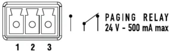
1 = normally open 2 = common 3 = normally closed
Max. voltage on contacts: 24 V; max. current: 0.5 A
[24] Amplifier output (max. 160 W) to speakers, available as:
- 100 / 70 V constant voltage line
- Low impedance (min. 4 Ω).
Use 1 output only (see the section 'Speaker connection').
[25] Mains connector with fuse
Before connecting the power supply cable, verify that the apparatus voltage (230 or 115 V ac) corresponds to the available mains supply.
Note: the fuse type is marked on the rear panel (below the mains connector).
[26] Antenna input (the antenna is necessary for Bluetooth).
MP3 PLAYER
flowchart
graph TD
    A["MP3 PLAYER"] --> B["SOURCE"]
    A --> C["PLAY/PAUSE"]
    A --> D["H"]
    A --> E["ST PAR ON/OFF"]
    B --> F["[36"]]
    C --> G["[37"]]
    D --> H["AUX IN"]
    E --> I["[38"]]
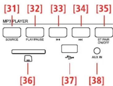
[31] SOURCE button: push to loop among MP3 sources (BT, SD CARD, USB and AUX IN).
[32] PLAY/PAUSE button: push to start the playback (if stopped) or toggle play / pause the current MP3 file.
[33] ▪◀◀ button
While playing:
- If pushed once (only) for a while, the MP3 file begins again.
- Push twice or more times quickly to select previous MP3 files.
- Push and hold for fast backward of the current MP3 file.
[34] ▶▶| button
While playing:
- Push once or more times quickly to select next MP3 files.
- Push and hold for fast forward of the current MP3 file.
[35] BT PAIR ON/OFF button with bicolour LED
- Push once (for an instant) to make it detectable (for about a minute) to the external Bluetooth device.
- Push and hold (at least 3 seconds) to disable Bluetooth (the LED lights off); push and hold (at least 2 second) to enable Bluetooth again).
| LED INDICATION | |
| OFF Bluetooth is disabled. | |
| BLUE (2 seconds) / OFF (1 second) loop | Bluetooth is enabled, but the player is in stand-by, waiting for pairing to the external device. |
| BLUE blinking every 2 seconds The player is connected to an external Bluetooth (A2DP) device. | |
| BLUE steady lit | The player is connected to an external Bluetooth (A2DP) device and is currently receiving streaming audio. |
| BLUE / RED alternate and continuous flashing | The player is currently detectable (for about a minute) by the external Bluetooth device. |
[36] 'Secure Digital' SD CARD SDHC port (max. 32 GB).
Do NOT insert an SD CARD if a USB flash-drive is already inserted into its respective port [37].
[37] Port for a USB flash drive (max. 32 GB).
The insertion of a USB flash drive is automatically detected.
Do NOT insert a USB flash drive if an SD CARD is already inserted into its respective port [36].
Notes about USB flash drives:
- Format: FAT 12 / FAT 16 / FAT 32.
- File name: 32 byte / dir. name: 32 byte / tag name: 32 byte.
- USB 1.1 support and also 2.0 (but at the same speed of USB 1.1).
Some USB flash drive types may not be compatible.
[38] AUX IN (1/8" TRS jack): MP3 player aux input to connect (via cable) the audio output of an external device.
To enable this input, it is necessary to remove the USB flash drive / SD CARD (if inserted) and / or disconnect the external Bluetooth device.
Note: do not confuse this input with the other AUX INPUT [14] on the rear panel.
INPUT / MEMORY AUTOMATIC SELECTION
The MP3 player automatically selects inputs / memories with different priority levels as follows:
- (highest priority) Bluetooth external device, if connected and sending streaming audio.
- When Bluetooth external device is playing and then disconnected, audio source won't do any switch automatically, and it will be needed to select the MP3 source with SOURCE button.
- When a MP3 source is playing and a Bluetooth device is connected, music will be switched to BT.
NOTES ABOUT MP3 FILES
- MP3: means MPEG Audio Layer 3 and refers to an audio compression type.
- This player reads MP3 files on USB flash drives and SD cards.
- The file extension must be .mp3.
- The max. directory (/ folder) level is 8, including the 'root'.
- It is advisable to use MP3 files having a sampling frequency of 44.1 kHz and a fixed bit-rate of at least 128 kbps (if higher, for instance 192 kbps, the sound quality will be better).
- The player may not play MP3 files in the order as written on the USB flash drive / SD CARD.
BLUETOOTH DEVICES
'Bluetooth' is a wireless technology standard for exchanging data over short distances from fixed and mobile devices (e.g. cellular phones).
The MP3 player includes a Bluetooth interface to receive audio signals from compatible external devices, which must have A2DP technology ('Advanced Audio Distribution Profile').
To connect your Bluetooth external device to the MP3 player:
- Check if the antenna [26] on the rear panel is properly connected and oriented.
- Enable 'Bluetooth' on the external device.
- Push the MP3 player BT PAIR ON/OFF button [35] (its LED now flashes blue / red).
- Within a minute, on the external device, start searching other devices with active Bluetooth; ES2160 should be displayed.
- Pair the external device and ES 2160.
- Start the audio playback on the external device (which should be now included in the available sources of the internal MP3 player).
When turning ES 2160 on, the MP3 player automatically tries to connect (via 'Bluetooth') to the last paired external device (if available).
AMPLIFIER OPERATION
'VOX' is an internal circuit that automatically activates the input 1 priority when a signal is detected on its sockets.
Power on (or when a priority command ends)
If no priority command is present (including VOX and SEQUENTIAL CHIME COMMAND), all the inputs 1, 2, 3, 4 and the MP3 PLAYER (or the AUX INPUT) are mixed together.
The music volume (either the MP3 PLAYER or the AUX INPUT source) depends on the front panel volume control [2] and also the respective GAIN control settings ( [15] or [16] ) on the rear panel.
Priority
If a priority command is present (or VOX), the MP3 PLAYER (or the AUX INPUT) can be either included in the mix sent to the amplifier or muted, according to dip-switch no.1 setting (see [20] : the eight dip-switch group).
During a priority command ('PRIOR' LED turns on), only the audio signal of the channel with priority (and the MP3 PLAYER / AUX INPUT, if enabled) is sent to the amplifier (and the PRE OUT output).
The MP3 PLAYER (or the AUX INPUT) is always muted in the mix sent to the amplifier when the CHIME SEQUENTIAL COMMAND is activated.
The priority mode and the VOX function are set through the dip-switches no.2 and no.3 of the eight dip-switch group (see [20]):
| DIP 2 DIP 3 MODE | |||
| ---- I/LCK INTERLOCKED | Only the first priority command of inputs 1 to 4 (and also channel 1 VOX, if enabled through the dip-switch no.4) is accepted.Any other later priority command will not be accepted until the previous is removed.Note: the only event that can always be activated later (and can override a previous priority) is the SEQUENTIAL CHIME CMD. . | ||
| PRIO IN1 GR. PRIOR. | GRADUATED PRIORITY 1GRADUATED PRIORITY 2 | A priority command having a higher level can override the previous one. The priority levels are:1. (highest) SEQUENTIAL CHIME CMD.2. input 1 (including VOX)3. input 24. input 35. input 4 | |
| PRIO IN2 GR. PRIOR. | A priority command having a higher level can override the previous one. The priority levels are:1. (highest) SEQUENTIAL CHIME CMD.2. input 23. input 1 (including VOX)4. input 35. input 4 | ||
The dip-switch no.2 (8 dip-switch group) allows you to switch the priority level between the inputs 1 and 2.
This setting does not work in the interlocked priority mode.
As soon as a priority event ends, the initial state will be restored (all the inputs 1, 2, 3, 4, the MP3 PLAYER or the AUX INPUT will be mixed together, unless another priority event is in progress).
Sequential Chime Cmd.
The SEQUENTIAL CHIME COMMAND makes the chime (either short or long, depending on the dip-switch no.8 setting, see [20] ) be continuously played. This command has the highest priority level and always mutes the MP3 player (or the aux input) in the mix sent to the amplifier.
Channel 2 - 3 'push' / 'toggle' priority mode
The dip-switches no.5 and no.6 (eight dip-switch group, see [20]) allow the choice of the priority mode for inputs 2 and 3 between 'push' (the priority is kept only if the command is still present) and 'toggle' (the priority is switched on / off by every impulse of the command).
Note: the chosen priority mode is applied to both BM 3001 paging microphones (if present) and priority commands (of removable connectors).
4 dip-switch group (one per each input 1 to 4)
Each input gain can be set to either MIC or -20 dBu (0 dBu for the input 1).
It is also possible to turn the PHANTOM power supply on/off, to insert or remove the high-pass filter and to enable or disable the chime, which is played on every priority event.
Information about the CHIME
The chime is not played when using the channel 1 VOX function (a priority command is needed to play the chime).
Its melody can be either short or long (dip-switch no.7 of the eight dip-switch group, see [20]).
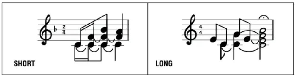
During the chime playback (a few seconds), the MP3 player (or the AUX INPUT) is not sent to the amplifier.
RCF BM 3001 paging microphone (not included)
Both inputs 2 and 3 have an RJ 45 socket, to which a single BM 3001 paging microphone can be connected (note: it is necessary to set the dip-switches no.3 and no.4 to the '-20 dBu + PHANTOM' mode, see [10], the second table).
When the BM 3001 paging microphone is on (ready to talk), its LED turns ON.
During the chime playback (if the chime is enabled), the BM 3001 microphone is momentarily muted.
The paging microphone priority mode depends on the settings mentioned above.
The paging microphone is muted by events having a higher priority level (than the input 2 or 3, to which the paging microphone is connected).
SPEAKERS CONNECTION
Use 1 output only, DO NOT MIX 100 / 70 V and 4 Ω CONNECTIONS!
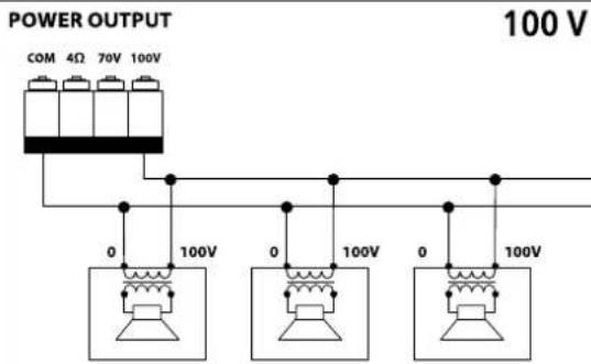
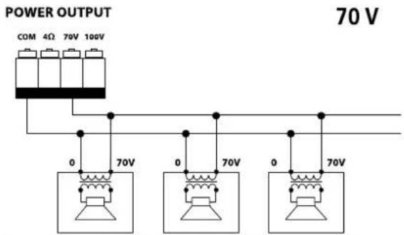
100 / 70 V CONSTANT VOLTAGE OUTPUTS
- Each speaker shall have a line transformer with the input voltage equal to the line voltage (100 / 70 V).
- The speaker total power shall not be higher than the amplifier maximum power (160 W).
POWER OUTPUT
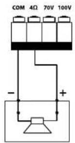
LOW IMPEDANCE OUTPUT (4 Ω)
- The speaker total impedance shall not be lower than 4 Ω. Note: a total impedance equal to 4 Ω allows the amplifier maximum power delivery. A higher impedance leads to a reduction of the power delivered by the amplifier (e.g. 8 Ω: approx. ½ power, 16 Ω: approx. ¼ power). An impedance lower than 4 Ω overloads the amplifier.
- Speaker models shall be chosen by considering the maximum power (160 W) that the amplifier can deliver.
- Speaker line should be as short as possible, as long cables may need large wire cross-sections.
- Do not use, at the same time, both the low impedance output (4 Ω) and the constant voltage output (100V or 70V), as this overloads the amplifier.
POWER SUPPLY VOLTAGE CHANGE
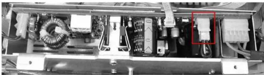
IMPORTANT: This manual section concerns qualified personnel only. The following instructions are to be ignored by the user.
- Make sure the amplifier is not connected to the mains (unplug the power cord).
- Remove the lid.
The voltage change connector is highlighted by a square.
natural_image
Interior view of an electronic device showing internal components like capacitors, inductors, and a highlighted connector (no visible text or symbols)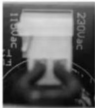 | If the mains voltage is 230 V, set the connector to the 230Vac position, according to the PCB indication (looking at the connector front, the central pin is connected to the right one). |
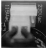 | If the mains voltage is 115 V, set the connector to the 115 Vac position, according to the PCB indication (looking at the connector front, the central pin is connected to the left one). |
Refit the amplifier lid.
Before connecting the amplifier to the mains, make sure that the fuse (inside the IEC power supply connector of the rear panel, see [25]) is the correct current rating for the mains voltages (read the fuse indication below the connector).
AVVERTENZE PER LA SICUREZZA
DISPOSITIVI "BLUETOOTH"
"Sequential Chime Cmd."
USCITA BASSA IMPEDENZA (4 Ω)
natural_image
Interior view of an electronic device showing internal components like capacitors, inductors, and wiring (no visible text or symbols)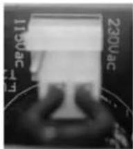
natural_image
Close-up of a hand holding a flat electronic device with visible power connections (no text or symbols)Number of channels: 1
Power output per channel (@ 4 ohm): 160 W RMS
Power output (@ 100V): 160 W RMS
Frequency Response (-3dB): 50 Hz ÷ 14 kHz
Distortion (THD+N) @ 1 kHz nominal power: <0.3 %
Input section
Total number of inputs: 8
Balanced: 7
Unbalanced: 2
Mono: 7
Stereo: 2
Line inputs: 2
Line connectors: RCA
Mic+Line inputs: 4
Mic+Line connectors: Euroblock, XLR
Mic+Line Phantom: 32 V DC
VOX: Yes
Paging inputs: 2
Paging connectors: RJ45
Paging command: Contact
General Purpose Inputs (GPI): 2
Output section
Signal output number: 2
Signal output connectors: RCA
Power output connectors: Euroblock
Processing
Tone controls: Y
High-pass filter: 150 Hz
Configuration: DIP switch, Front panel
Priority: Yes
Music on hold: Yes
Chime tone: Yes
Protections
Cooling: Convection
Short circuit: Yes
Thermal: Yes
DC: Yes
Fuses: Yes
Audio sources
USB pen drives: Yes
SD card: Yes
Bluetooth: Yes
Power requirement
Operating voltage: 220-240/115 V\~ 50/60Hz
Voltage selection: Internal
ES 2160
| Power consumption: 350 W |
Standard compliance
| CE marking: Yes |
Physical specifications
| Cabinet/Case Material: Metal |
| Colour Black |
| Rack mounting: 19", 2U |
Size
| Height: 88 mm / 3.46 inches |
| Width: 442 mm / 17.4 inches |
| Depth: 230 mm / 9.06 inches |
| Weight: 5.4 kg / 11.9 lbs |

- ITALIANO
- SAFETY PRECAUTIONS AND GENERAL INFORMATION
- IMPORTANT NOTES
- SAFETY PRECAUTIONS
- OPERATING PRECAUTIONS
- CORRECT DISPOSAL OF THIS PRODUCT
- CARE AND MAINTENANCE
- DESCRIPTION
- FRONT PANEL
- REAR PANEL
- MP3 PLAYER
- [34] ▶▶| button
- [35] BT PAIR ON/OFF button with bicolour LED
- INPUT / MEMORY AUTOMATIC SELECTION
- NOTES ABOUT MP3 FILES
- BLUETOOTH DEVICES
- AMPLIFIER OPERATION
- Power on (or when a priority command ends)
- Priority
- Sequential Chime Cmd.
- Channel 2 - 3 'push' / 'toggle' priority mode
- dip-switch group (one per each input 1 to 4)
- Information about the CHIME
- RCF BM 3001 paging microphone (not included)
- SPEAKERS CONNECTION
- / 70 V CONSTANT VOLTAGE OUTPUTS
- LOW IMPEDANCE OUTPUT (4 Ω)
- POWER SUPPLY VOLTAGE CHANGE
- AVVERTENZE PER LA SICUREZZA
- DISPOSITIVI "BLUETOOTH"
- "Sequential Chime Cmd."
- USCITA BASSA IMPEDENZA (4 Ω)
- Input section
- Output section
- Processing
- Protections
- Audio sources
- Power requirement
Brand : RCF
Model : ES 2160
Category : Mixing console