LiveWire 961350PT - Uncategorized Cleco - Free user manual and instructions
Find the device manual for free LiveWire 961350PT Cleco in PDF.


| Product Type | Power Module (PM48) for cordless EC tools |
| Model | LiveWire 961350PT |
| Brand | Cleco |
| Input Voltage | 85 to 276 VAC |
| Power Supply Frequency | 47 to 63 Hz |
| Output Voltage | 47.5 to 48.5 VDC |
| Output Current (Continuous) | 10 A |
| Output Current (Max 4 s) | 15 A |
| Peak Output | 750 A |
| Protection Category | IP54 |
| Weight | 3 kg (6.6 lbs) |
| Ambient Temperature (Operation) | +5 °C to +40 °C |
| Storage Temperature | -20 °C to +70 °C |
| Relative Humidity | 0% to 90% |
| Input Power | Wide-range input 85-276 VAC |
| LED Indicators | Green (DC OK), Red (Overload), Red flashing (Continuous overload) |
| Housing | Solid metal with keyholes for mounting |
| Fuses | 2 × Bussmann S506-6.3A, medium-duty |
| Maximum Total Cable Length | 20 m (for PM48 adapter cables) |
| Intended Use | Supply power to Cleco cordless EC tools (PM48) or mini-spindle (PM48 LAN) |
Frequently Asked Questions - LiveWire 961350PT Cleco
User questions about LiveWire 961350PT Cleco
0 question about this device. Answer the ones you know or ask your own.
Ask a new question about this device
Download the instructions for your Uncategorized in PDF format for free! Find your manual LiveWire 961350PT - Cleco and take your electronic device back in hand. On this page are published all the documents necessary for the use of your device. LiveWire 961350PT by Cleco.
USER MANUAL LiveWire 961350PT Cleco
natural_image
Two red and black electronic devices labeled 'LIVEWIRE™ Vmax' with visible branding, connected by wires (no readable text beyond branding)Copyright © Apex Tool Group, 2019
No part of this document may be reproduced in any way or in any form, in whole or in part, or in a natural or machine-readable language, or transmitted on electronic, mechanical, optical, or other media, without the express permission of the Apex Tool Group.
Disclaimer
Apex Tool Group reserves the right to modify, supplement, or improve this document or the product without prior notice.
Trademark
Cleco is a registered trademark of Apex Brands, Inc.
Apex Tool Group GmbH
Industriestraße 1
73463 Westhausen
Germany
01
03
04
natural_image
Close-up of a black plastic connector with an arrow pointing to it, shown from two angles (no text or symbols visible)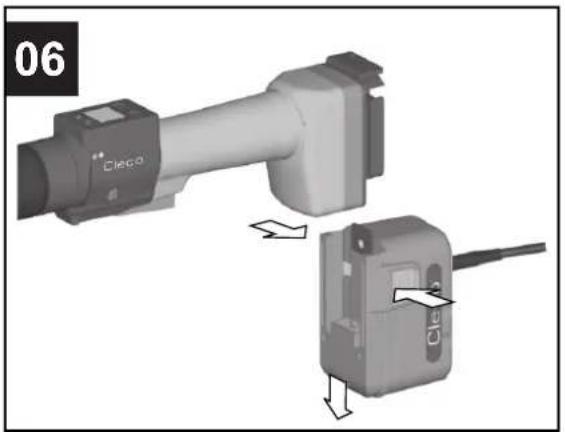
Contents
EN
1 About this Document 9
2 Safety 9
3 Storage.... 10
4 Product description.... 10
5 Initial operation .... 11
6 Maintenance.... 11
7 Technical Data.... 11
8 Troubleshooting.... 12
9 Cable PM48.... 13
10 Cable PM48 LAN.... 13
11 Service 14
12 Disposal.... 14
DE
The original language of this document is German.
This document is intended for all persons who will operate and maintain this equipment.
This document has the following purposes:
- It provides important instructions for safe and effective operation.
- It describes the function and operation of this equipment.
- It serves as a reference guide for technical data and service intervals.
- It provides information regarding optional equipment.
Other documents
| Number Name | |
| P2291BA Instruction Manual Cordless EC Tools | |
| P2280PM Programming Manual mPro400GC(D) | |
| P3225C EC Declaration of Conformity | |
Symbols in the text
italic Menu options (e.g., Diagnostics) input fields, check boxes, radio buttons or dropdown menus.
Indicates selection of a menu option from a menu, e.g., File > Print
<...> Specifies switches, pushbuttons or the keys of an external keyboard, e.g.,
Courier Filenames and paths, e.g., setup.exe
- List - List, level 2
a) Options
b) Result
-
(...) Action steps
-
(...)
▶ Single action step
Symbols in Graphics
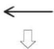
Movement in one direction
Function and force
Abbreviation
| Abbreviation | Description |
| PM48 | Power Modul PM48 |
| PM48 LAN | Power Modul PM48 LAN |
| Order no. Order number | |
2 Safety
▶ Only operate the tool after you have read and fully understood this document. Failure to follow the directions and safety instructions could result in an electric shocks, burns and/or serious injuries.
Keep this document in a safe place for future reference! These safety instructions must be accessible to the operator at all times. They must be available to all persons using or repairing the device.
2.1 Warnings and Notes
Warnings and notices
Warning notices are identified by a signal word and a pictogram:
- The signal word describes the severity and the probability of the impending danger.
• The pictogram describes the type of danger

Danger
A symbol combined with the word Danger indicates a hazard with a high level of risk which, if not avoided, will result in death or serious injuries.

Warning
A symbol combined with the word Warning indicates a hazard with a medium level of risk which, if not avoided, could result in death or serious injury.

Caution
A symbol combined with the word Caution indicates a hazard with a low level of risk which, if not avoided, could result in minor or moderate injury.

Note
A symbol combined with the word Note indicates a potentially harmful situation which, if not avoided, could result in damage to property or the environment.

General instructions include application tips and useful information, but no warnings against hazards.
Structure Of Warnings

Caution
Type and source of danger.
Possible consequences of non-observance.
▶ Measures to avoid danger.
2.2 Intended Use
This product is part of the Cleco Production Tools' tightening system. It is intended for use in industrial fastening processes. Only use the tool under the following conditions. The user is liable for damage caused by improper use.
- The Power ModulePM48 is only intended for use to supply electrical power to the Cleco cordless EC tool.
- The Power Module PM48 LAN is only intended to supply power and data to the Cleco mini-spindle.
- Do not use it in areas where there is a risk of explosion.
▶ Do not open the power module.
▶ Do not modify the power module structurally.
▶ Operate the power module in dry, enclosed rooms only.
▶ Protect the power module from moisture and rain.
▶ Never operate the power module under unsuitable ambient conditions (i.e. where combustible gases, solvents, dust, vapors or moisture is present).
▶ Do not operate the power module if the housing or power plug are damaged.
▶ Do not use damaged cables.
2.4 Workstation
▶ Ensure that there is enough space in the work area.
▶ Keep the work area clean and dry.
2.5 Items supplied
Check shipment for transit damage and ensure that all items have been supplied:
- Power module
• EU power cable - NA power cable
- GB power cable
- Instruction Manual
2.6 Transport
Transport and store the module in its original packaging. This packaging can be recycled.
3 Storage
| Features Data | |
| Storage temperature | -20 °C to +70 °C (-4 °F to 158 °F) |
| Relative humidity | 0 % to 90 % |
4 Product description
The PM48 Power Module supplies power to a cordless EC tool and replaces the battery pack. Quickly and flexibly, the advantage of cordless and cabled tools can be utilized.
The PM48 LAN Power Module supplies power and data to a mini-spindle. It is used whenever there is a wish not to use radio / wireless technology.
- The higher voltage of 48 VDC (compared to a 26 V Li-lon battery) increases the speed of the tool by up to 83 %.
• Wide-range input 85 VAC to 276 VAC - Operating mode display of mains power supply and status with 2 LEDs.
- Short-circuit-proof
• Electronic monitoring - Solid metal housing
- Low weight
- Easy to install with 4 keyholes in the housing.
4.1 System overview – optional accessories
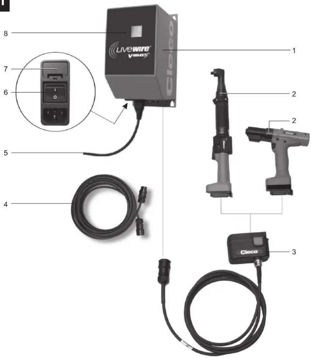
4.1.1 PM48
Item see figure 01, page 3.
| Item Designation | |
| 1 Power Module 961350PT (scope of supply) | |
| 2 Tool series 17BP.../ 47BA... | |
| 3 Adapter, see 9.1 Adapter: PM48 tool, Seite 13 | |
| 4 Extension, see 9.2 Extension: PM48 adapter,Seite 13 | |
| 5 Power cable, EU, NA, GB (scope of supply) | |
| 6 On/Off switch | |
| 7 2 × fuse, Bussmann, Product Code S506-6.3A,medium-duty (scope of supply) | |
| 8 LED display |
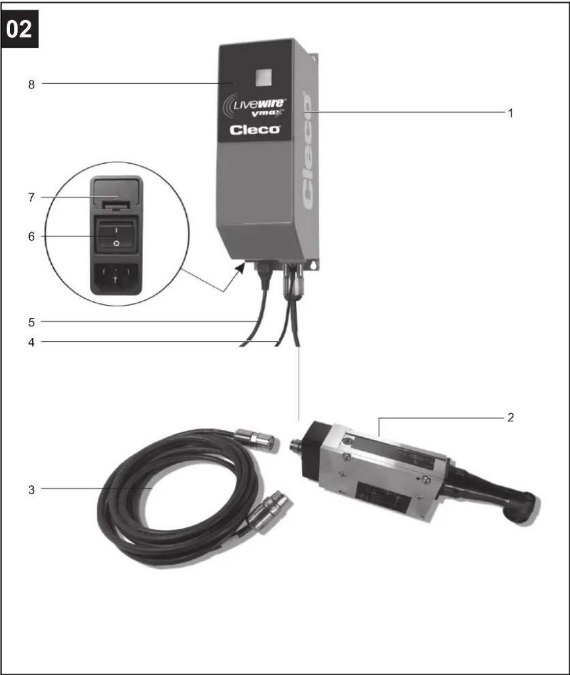
4.1.2 PM48 LAN
Item see figure 02, page 4.
| Item Designation | |
| 1 Power Module 961466PT (scope of supply) | |
| 2 Tool series 73-754-47CAXB15AM3-SO | |
| 3 Tool cable, LAN, see 10.1 LAN tool LAN,Seite 13 | |
| 4 Ethernet connection cable | |
| 5 Power cable, EU, NA, GB (scope of supply) | |
| 6 On/Off switch | |
| 7 2 × fuse, Bussmann, Product Code S506-6.3A,medium-duty (scope of supply) | |
| 8 LED display |
4.1.3 LED display
Two LEDs behind front plate.
| LED Operating status | Result | |
| Green continuous light | DC – OK 48 VDC | present |
| Red continuous light | Overload 48 VDC | over-load or short-circuit |
| Red flashing light (1 Hz) | Overload 48 VDC | over-load or short-circuit |
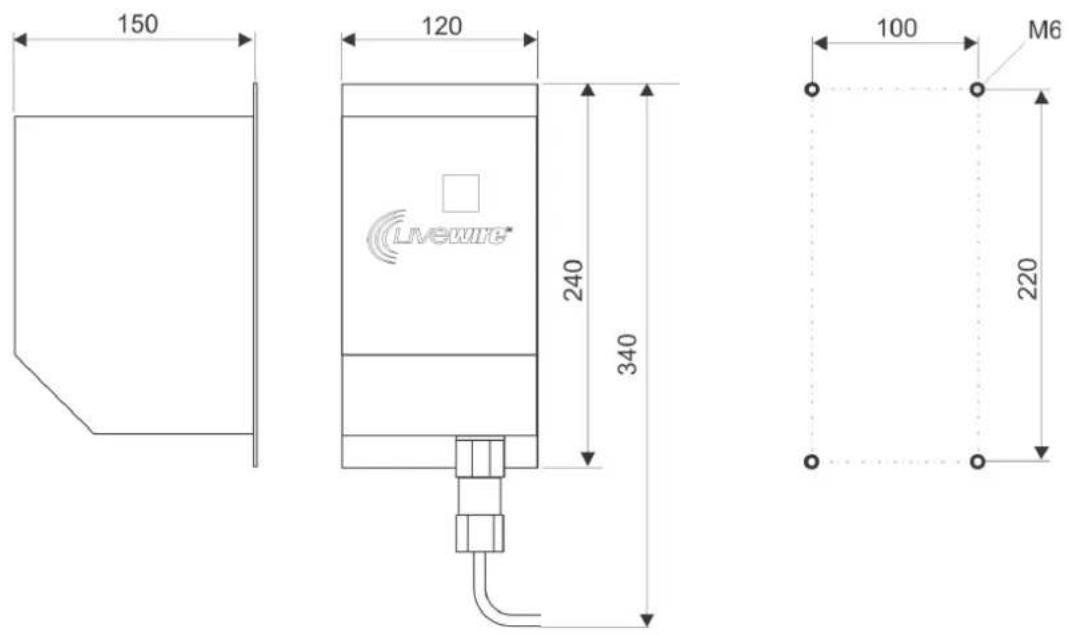
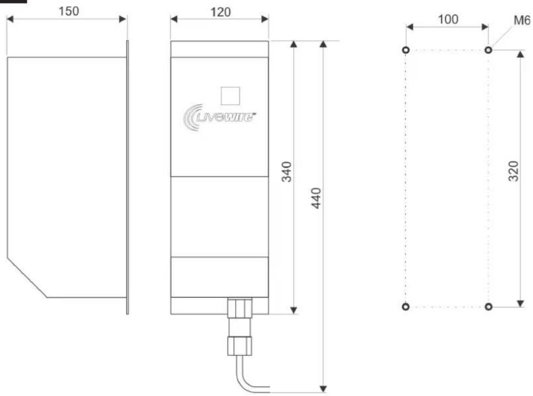
4.2 Dimensions in mm – drilling plan
PM48: See figure 03, page 5.
PM48 LAN: See figure 04, page 5.
5 Initial operation
5.1 Hardware

Note
Damage to adapter cable.
Do not reconnect adapter cable until approx. one minute has elapsed.
▶ Compensating currents between mains power unit and adapter cable may otherwise damage the contacts.

▶ Operate the system only when the slide lock of the plug is closed.
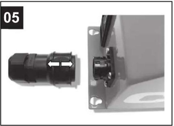
- Plug adapter cable and/or tool cable into the Power Module (PM48 or PM48LAN). The connectors are equipped with sliding locks. See figure 05, page 6.
- Only PM48: Slide adapter cable and/or extension cable into guide in tool until the locking unit engages securely. See figure 06, page 6.
To remove the adapter cable, press together the locks and remove the joining piece from the handle. - Connect the power module to the power supply.
- Turn on the power switch.
→ The green LED DC – OK signals: power supply and 48 VDC output voltage present.
5.2 Software

The tool is ready for operation with the Power Module with effect from: Servo firmware T10C / measuring board software 2.00.05.
The increased Speed Setpoint (up to 83%) is only achieved with the named software.
Check installed on the LCD display:
Servo firmware
- Press right-hand function key: Main menu > Administration > Servo.
See document P2291BA. - To update the servo firmware, contact Sales & Service Centers Service Center.
Measuring board software
-
Press right-hand function key: Main menu > Administration > Servo. See document P2291BA.
-
To update the measuring board software, contact Sales & Service Centers Service CenterCleco.
-
Update the software using the controller (see document P2280PM).

Only remove tool and cable when mains power supply is isolated, i.e. switched off.
6 Maintenance
▶ Keep the contacts on the Power Module and the accumulator free of dirt. This is the only way to ensure that the Power Module functions properly.
7 Technical Data
| Features Data | |
| Supply voltage 85 to 276 VAC | |
| Power supply frequency 47 to 63 Hz | |
| Rated output | 200 A |
| Peak output | 750 A |
| Rated output voltage | 47,5 to 48,5 VDC |
| Output current | 10 A |
| Output current max. 4 s 15 A | |
| Protection category | IP54 |
| Weight PM48 | 3 kg (6.8 lbs) |
| Weight PM48 LAN | 4 kg (6.8 lbs) |
| Ambient temperature | +5 °C to +40 °C |
| Relative humidity | 0 to 90 % |
8 Troubleshooting
| Error Cause Measure | ||
| The green DC OK LED is not illuminated when the power supply is connected. | No power supply voltage. ▶ Check and restore the power supply voltage. | |
| Power cable defective. ▶ Replace power cable. | ||
| Defective fuse in the power supply module. | ▶ Replace 6.3 AMT fuse, see 4.1 System overview – optional accessories, Seite 10. | |
| Power module defective. ▶ Replace power module. | ||
| Power module overloaded. ▶ Switch off the power supply and switch it back on after approx. 30 sec. | ||
| The red Overload LED is illuminated. | Overload of the 48 VDC output voltage. | ▶ Check EC tool and cable for damage. |
| Short circuit in the adapter cable. ▶ Replace the adapter cable. | ||
| Short-circuit in the EC tool. ▶ Replace EC tool. | ||
| EC tool requires too much power. ▶ Check EC tool for damage and replace if necessary. | ||
| The temperature of the power module is too high. | ▶ Decrease the ambient temperature to <40°C (104°F). | |
| The red Overload LED flashes at a frequency of approx. 1 Hz. | Continuous overload of the 48 VDC output voltage. | ▶ Check EC tool and cable for damage. |
| Short circuit in the adapter cable. ▶ Replace the adapter cable. | ||
| Short-circuit in the EC tool. ▶ Replace EC tool. | ||
| EC tool requires too much power. ▶ Check EC tool for damage and replace if necessary. | ||
9 Cable PM48

Do not exceed a total cable length of 20 m.
9.1 Adapter: PM48 tool
| Order no. (aluminium) | Order no. (plastic) | Length |
| 961341-030 961 | 341-030 3 m | |
| 961341-060 961 | 341-060 6 m (19.6 ft.) | |
| 961341-080 961 | 341-080 8 m | |
| 961341-100 961 | 341-100 10 m (33 ft) |
Assignment of the contacts
| Contact on connector | Contact on adapter | Assignment |
| A 1 +48 VDC | ||
| B 1 +48 VDC | ||
| C | - | n |
| D 3 0 VDC | ||
| E 3 0 VDC |
9.2 Extension: PM48 adapter
| Order no. Length | |
| 961342-030 3 m | |
| 961342-060 6 m (19.6 ft.) | |
| 961342-080 8 m | |
| 961342-100 10 m (33 ft) | |
9.3 Assignment of the contacts
| Contact on connector pin | Contact on connector socket | Assignment |
| A A +48 VDC | ||
| B B +48 VDC | ||
| C | C | n |
| D D 0 VDC | ||
| E E 0 VDC |
9.4 Cable properties
| Features Data | |
| Thermal properties | |
| Ambient temperature | -40 °C to +80 °C |
| Chemical properties of the coating | |
| Features Data | |
| Coating material | PUR, low-adhesion, resistant to hydrolysis and microbes, UV-resistant, abrasion-resistant, tear-resistant, cut-resistant, notch-resistant |
| Oil resistance | Oil-resistant in accordance with DIN VDE 0472, part 803 ASTM oil 1 to 3 and HD 505.2.1 |
| Mechanical properties | |
| Diameter approx. 7.2 mm | |
| Minimum bending radii | |
| Single bends | 30 mm |
| Alternate bending | 70 mm |
| Torsional length( ±360 ° around separatecentral axis) | 1000 mm |
10 Cable PM48 LAN
10.1 LAN tool LAN
| Order no. Length | |
| 961465-040 4 m | |
10.2 Assignment of the contacts
| Contact on connector | Contact on plug | Assignment |
| 3 | 3 +48 VDC | |
| 4 | 4 +48 VDC | |
| 1 | 1 0 VDC | |
| PE | PE | 0 VDC |
| A A Data | ||
| B B Data | ||
| C C Data | ||
| D D Data |
10.3 Cable properties
| Features Data | |
| Thermal properties | |
| Ambient temperature | -40...+80 °C |
| Chemical properties of the coating | |
| Coating material | PUR, low-adhesion, resistant to hydrolysis and microbes, UV-resistant, abrasion-resistant, tear-resistant, cut-resistant, notch-resistant |
| Features | Data |
| Oil resistance Oil-resistant | in accordance with DIN VDE 0472, part 803ASTM oil 1 to 3 and HD 505.2.1 |
Mechanical properties
| Diameter approx. 9.7 mm | |
| Minimum bending radii | |
| Single bends | 30 mm |
| Alternate bending | 100 mm |
| Torsional length( ±360 ° around separatecentral axis) | 1000 mm |
10.4 Ethernet patch cable
PM48 LAN – network
| Order no. Designation Length | ||
| S965412 Ethernet patch cable, CAT5 2 m | (6.6 ft) | |
| S961365 Ethernet patch cable, CAT5 4 m | (13.1 ft) | |
| S961568 Ethernet patch cable, CAT5 5 m | (16.4 ft) | |
| S965413 Ethernet patch cable, CAT5 10 m | (32.8 ft) | |
| S965414 Ethernet patch cable, CAT5 14 m | (45.9 ft) | |
| S965415 Ethernet patch cable, CAT5 22 m | (72.2 ft) | |
| S965416 Ethernet patch cable, CAT5 26 m | (85.3 ft) | |
| S965417 Ethernet patch cable, CAT5 34 m | (111.5 ft) | |
| 543445-7 Ethernet patch cable, CAT5 2.1 m | (6.9 ft) | |
| 543445-25 Ethernet patch cable, CAT5 7.6 m | (24.9 ft) | |
| 543445-50 Ethernet patch cable, CAT5 15.2 m | (49.9 ft) | |
| 543445-100 | Ethernet patch cable, CAT5 30.4 m (99.9 ft) | |
Maximum length of the Ethernet patch
cables + tool cable = 100 m (328' 1").
The Ethernet patch cables comply with the UTP/STP Category 5 (EIA 568B, Cat 5) standards or better.
11 Service

If repair is required send the complete 47BA to Sales & Service Centers. Repairs on the gears and angle attachment are only permitted by Cleco authorized personnel. If the tool is opened, the warranty is voided.
12 Disposal
Injuries and environmental damage from improper disposal.
Components and auxiliary materials of the tool pose risks to the health and the environment.
▶ Catch auxiliary materials (oils, greases) when drained and dispose of them properly.
Separate the components of the packing and segregate the different materials before disposing of them.
▶ Follow the locally applicable regulations.

Observe generally valid disposal guidelines such as, in Germany, the Electrical and Electronic Equipment Act (ElektroG) and the Battery Act (BattG).
Wasted rechargeable batteries must be disposed of. Return the tool and defective / power supplies to your company collection facility or to Sales & Service Centers.
Please note that all locations may not service all products.
Contact the nearest Cleco® Sales & Service Center for the appropriate facility to handle your service requirements.

Sales Center
Service Center
NORTH AMERICA | SOUTH AMERICA-
DETROIT, MICHIGAN
Apex Tool Group
2630 Superior Court
Auburn Hills, MI 48236
Staffordshire B78 2ER
United Kingdom
Phone: +44 1827 8727 71
Fax: +44 1827 8741 28
FRANCE
Apex Tool Group SAS
25 Avenue Maurice Chevalier - ZI
77330 Ozoir-La-Ferrière
France
Phone: +33 1 64 43 22 00
Fax: +33 1 64 43 17 17
GERMANY
Apex Tool Group GmbH
Industriestraße 1
73463 Westhausen
Germany
Phone: +49 (0) 73 63 81 0
Fax: +49 (0) 73 63 81 222
HUNGARY
Apex Tool Group
Hungária Kft.
Platánfa u. 2
9027 Györ
Hungary
Phone: +36 96 66 1383
Fax: +36 96 66 1135
ASIA PACIFIC
AUSTRALIA
Apex Tool Group
519 Nurigong Street, Albury
NSW 2640
Australia
Phone: +61 2 6058 0300
CHINA
Apex Power Tool Trading
(Shanghai) Co., Ltd.
2nd Floor, Area C
177 Bi Bo Road
Pu Dong New Area, Shanghai
China 201203 P.R.C.
Phone: +86 21 60880320
Fax: +86 21 60880298
INDIA
Apex Power Tool India
Private Limited
Gala No. 1, Plot No. 5
S. No. 234, 235 & 245
Indialand Global
Industrial Park
Taluka-Mulsi, Phase I
Hinjawadi, Pune 411057
Maharashtra, India
Phone: +91 020 66761111
JAPAN
Apex Tool Group Japan
Korin-Kaikan 5F,
3-6-23 Shibakoen, Minato-Ku,
Tokyo 105-0011, JAPAN
Phone: +81-3-6450-1840
Fax: +81-3-6450-1841
KOREA
Apex Tool Group Korea
1503, Hibrand Living Bldg.,
215 Yangjae-dong,
Seocho-gu, Seoul 137-924,
Korea
Phone: +82-2-2155-0250
Fax: +82-2-2155-0252
Cleco®
Production Tools
- Disclaimer
- Trademark
- Apex Tool Group GmbH
- Contents
- EN
- DE
- Symbols in the text
- Symbols in Graphics
- Safety
- Warnings and Notes
- Warnings and notices
- Danger
- Warning
- Caution
- Note
- Structure Of Warnings
- Intended Use
- Workstation
- Items supplied
- Transport
- Storage
- Product description
- System overview – optional accessories
- PM48
- PM48 LAN
- LED display
- Dimensions in mm – drilling plan
- Initial operation
- Hardware
- Software
- Servo firmware
- Measuring board software
- Maintenance
- Technical Data
- Troubleshooting
- Cable PM48
- Cable PM48 LAN
- Ethernet patch cable
- Service
- Disposal
- NORTH AMERICA | SOUTH AMERICA-
- ASIA PACIFIC
- 1503, Hibrand Living Bldg.,
Brand : Cleco
Model : LiveWire 961350PT
Category : Uncategorized