
BMM2000 - Multimeter Megger - Free user manual and instructions
Find the device manual for free BMM2000 Megger in PDF.


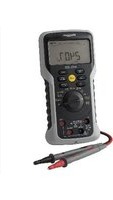
| Product Type | Insulation and Continuity Tester / Multimeter |
| Brand | Megger |
| Model | BMM2000 |
| Dimensions (H x W x D) | 110 mm x 220 mm x 45 mm |
| Weight | 742 g |
| Power Supply | 6 x 1.5 V alkaline cells (LR6/AA) or NiCd rechargeable |
| Insulation Test Voltages (DC) | 250 V, 500 V, 1000 V |
| Continuity Range | 0.01 Ω to 99.9 Ω |
| Resistance Range | 0.01 kΩ to 9.99 MΩ |
| Voltage Range (DC/AC) | ±1 V to ±500 V |
| Millivolt Range (DC/AC) | ±0.1 mV to ±1999 mV |
| Milliamps Range (DC/AC) | 0.1 mA to 500 mA (not ESD model) |
| Frequency Measurement | 16 Hz to 460 Hz (on AC V, mV, mA) |
| Display | Large LCD with digital and analogue scales, backlit |
| Safety Rating | Double insulation, IEC 1010-1 Cat III, 300 V phase to earth, 500 V phase to phase |
| Ingress Protection | IP54 (dust and water resistant) |
| Auto Shut-Off | After 10 min (insulation), 5 min (other ranges); configurable to 60 min |
| Battery Life (typical) | 2100 x 5-sec 1 kV tests; 3200 x 5-sec 500 V tests |
| Operating Temperature | -5 °C to +40 °C |
| Storage Temperature | -25 °C to +65 °C |
| Accessories Included | Test lead set (6220-437), test-&-carry case (6420-123) |
| Fuse | 500 mA (F) 500 V, 32 x 6 mm ceramic HBC |
Frequently Asked Questions - BMM2000 Megger
User questions about BMM2000 Megger
0 question about this device. Answer the ones you know or ask your own.
Ask a new question about this device
Download the instructions for your Multimeter in PDF format for free! Find your manual BMM2000 - Megger and take your electronic device back in hand. On this page are published all the documents necessary for the use of your device. BMM2000 by Megger.
USER MANUAL BMM2000 Megger
Megger.BMM2000 Series Insulation Multimeters
User Guide

WARNINGS
SAFETY
- Safety Warnings and Precautions must be read and understood before the instrument is used. They must be observed during use.
- The circuit under test must be de-energised and isolated before connections are made except for voltage measurement.
• Circuit connections must not be touched during a test. - After insulation tests, capacitive circuits must be allowed to discharge before disconnecting the test leads.
- The Live Circuit Warning and Automatic Discharge are additional safety features and should not be regarded as a substitute for normal safe working practice.
- Replacement fuses must be of the correct type and rating. Failure to fit the correctly rated fuse will result in damage to the instrument in the event of an overload.
- Test leads, including crocodile clips, must be in good order, clean and have no broken or cracked insulation.
- Ensure that hands remain behind guards of probes/clips when testing.
- U.K. Safety Authorities recommend the use of fused test leads when measuring voltage on high energy systems.
NOTE
THE INSTRUMENTS MUST ONLY BE USED BY SUITABLY TRAINED AND COMPETENT PERSONS
Users of this equipment and/or their employers are reminded that Health and Safety Legislation require them to carry out valid risk assessments of all electrical work so as to identify potential sources of electrical danger and risk of electrical injury such as from inadvertent short circuits. Where the assessments show that the risk is significant then the use of fused test leads constructed in accordance with the HSE guidance note GS38 ‘Electrical Test Equipment for use by Electricians’ should be used.
Symbols used on the instruments are:

Caution, risk of electric shock.

Caution, refer to User Guide.

Equipment protected throughout by Double Insulation (Class II).

Equipment complies with current EU Directives.
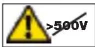
Equipment must not be connected to installations >500V.
GENERAL DESCRIPTION
The Megger BMM2000 Series instruments are battery powered Insulation and Continuity testers, with a measurement capability from 0,01Ω Continuity to 200GΩ Insulation.
Offering multi-voltage facilities, the instruments take full advantage of microprocessor technology and feature a large liquid crystal display combining digital and analogue readings. The analogue display has the benefit of indicating trends and fluctuations in readings, while the digital readout gives direct accurate results. The display is also backlit giving clear visibility even in low light conditions.
The BMM2000 Series instruments have the unique capability of being able to measure voltages down to a resolution of 0,1mV. This gives the user the option to fit a wide variety of transducers to further enhance the capabilities of the BMM Series instruments, eg temperature or humidity measurement.
A customised connector on the top of the instrument enables the optional Megger SP6F Switched Probe to be used for two handed probe operation.
The 250V, 500V and 1000V ranges can be used to test electrical installations in compliance with BS7671 (16th Edition IEE Wiring Regulations) IEC364 and HD384, since each range has a 1mA minimum test current at the minimum pass values of insulation specified in these documents. The 100V range is ideal for testing telecommunications equipment which would be damaged by higher voltages. The 50V range is useful for testing sensitive equipment, such as electronic components, and computer peripherals.
The BMM2000 series instruments have a current facility which enables up to 500mA to be measured, (not ESD models), this together with , V and mV ranges means that the instrument can realistically be used in situations where previously a multimeter would be needed. For higher currents an optional current clamp is available.
Designed to IEC1010-1 the BMM2000 Series are protected against connection to a 500V Category III supply. The instruments have a basic accuracy of ±2% at 20°C. The instruments are waterproof and dustproof to IP54. This helps maintain accuracy and ensures maximum reliability in harsh environments.
OPERATION

Refer to Safety Warnings before using the instrument
Testing is automatically inhibited if:
- An external voltage >25V is present when switched to any insulation range position.
- An external voltage >10V is present on all other ranges (excluding OFF/V).
The external voltage is indicated on the display, on insulation ranges an audible bleeper will sound if a test is attempted.
Live Circuit Warning
When more than 25V (10V on 10V insulation range) is applied to the terminals in the insulation ranges, the instrument defaults to a voltmeter and gives an audible warning if a test is attempted. On all other switch positions except OFF/V when approx 10V is applied the default voltmeter will be activated. Testing will be inhibited.
Voltage Testing on High Energy Systems
Use extreme care when using or measuring voltages above 30V, particularly in high energy systems. Fused test leads are available as optional accessories for local situations where increased protection is required.
Auto-shut Off
To conserve battery life, Auto-shut Off (preceded by a series of bleeps) operates after approx. 10 minutes of instrument inactivity on insulation, 5 minutes on all other ranges. If the instrument is switched on whilst holding the key, the Auto shut-off time is extended to 60 minutes. To restore operation after Auto-shut Off, either select OFF followed by the required switch position.
Note: It is recommended that the instrument is switched to the OFF position when not in use.
Backlight
The backlight is activated by pressing the key. The backlight will remain illuminated for approx. one minute before automatically switching off to conserve battery life, alternatively the key can be re-pressed.
Insulation Tests (MΩ) (See fig. 1)
The insulation tests apply a known voltage to the circuit under test and measure the resulting leakage current. The circuit under test must be completely de-energised and isolated before test connections are made.
Insulation tests are only initiated when the TEST button is pressed.
- Set the range switch to the test voltage required.
- Connect the test leads, first to the instrument, and then to the isolated item under test.
- Press the TEST button to activate the test voltage. Take the reading.
- Release the TEST button at the end of the test.
- Any capacitive circuits charged during a test will automatically discharge. If significant voltage remains the voltage warning will occur and the voltage present displayed.
- Remove the test leads only when no voltage is indicated.
Locking Test Button (Itb)
When it is desired to do a long insulation test, the test can be 'locked on' by pressing the key while the test button is held down. The warning will appear on the display and both buttons may be released whilst the test continues. The next press of the test button will terminate the test.
Note: There is a short delay on the first operation of '1000V' range, each time the range is selected. This is to prevent accidental application of 1kV.
The MΩ range features a leakage current display. Leakage current is the value of current that flows during the insulation test. To view the leakage current press the key. To view insulation resistance press the key again.


Good Procedure Whilst Insulation Testing
Care must be taken when taking measurements greater than a few GΩ. The leads must be clean dry and in good condition. They must also not be allowed to tangle. It is also advisable that the switched probe SP6F is not used as the accuracy at high value measurements is not guaranteed. The instrument should also be clean and dry with particular attention paid to the terminals. Also attempt to reduce any leakage that may give erroneous results on the item under test.
Polarisation Index Testing
Polarisation Index (PI) is the term applied to the Dielectric Absorption Ratio when resistance values are measured after 1 minute and again after 10 minutes. Polarization Index is then the resistance value after 10 minutes divided by the resistance value after 1 minute. The test can be run at any voltage. More detailed information on PI Testing and value assessment can be found in Megger Limited publications listed in the Accessories page.
Automatic Discharge
When the TEST button is released after an insulation test (or re-pressed if Itb feature is enabled), a 200kΩ load is automatically switched across the terminals to discharge the item under test. Any voltage present will be indicated on the display so that the discharge can be monitored.
TYPICAL TERMINAL VOLTAGE CHARACTERISTICS

line
| RESISTANCE (mA) | VOU (mA) | | --------------- | -------- | | 0.01 | 100 | | 5.1 | 300 | | 1 | 500 | | 10 | 1000 | | 100 | 1000 | | 1000 | 1000 |50V - 1000V Ranges

10V Range
Continuity Testing (Ω) (See fig.2)
The continuity tests are activated when the probes make contact of less than a few kΩ. The tests apply a constant current and measure the resulting volt drop across the circuit under test. The test operates without the need to press the TEST button. When the test leads are removed the reading will hold for a few seconds and then reset. To recall the last result press the key. This range is not suitable for diode testing since the automatic contact detector will not be activated when connected to a diode.

- Set the selector switch to .
- Connect the test leads.
- The test will activate automatically.
- After the test probes are disconnected, the reading will be held for a few seconds.
Zeroing of Test Lead Resistance
The resistance of the test leads can be nulled on the continuity range (up to 9,99Ω). The null information is retained in non-volatile memory and so will be remembered when the instrument is switched off.
- Select the Continuity range.
- Short the test leads across a known good conductor using prods.
- When the reading has stabilised, press the TEST button. The zero offset symbol will appear.
- To release the zero offset press the TEST button again.
The continuity range features a range lock facility. To LOCK the continuity range press the key, the LOCK symbol will appear. To scroll through the available ranges press the key. To de-select the LOCK feature hold the key down.
Possible sources of error
Measurements and results can be effected by the following:
• The impedance of operating circuits connected in parallel
- Impedance such as inductors that vary during the measurement
• A poor connection to the circuit under test.
Continuity Bleeper

The continuity bleeper sounds continuously when less than 5 is detected. Short bleeps will sound for resistances lower than a few k and above 5 .
- Set the selector switch to
- Connect the test leads.
- Set the selector switch to
- Connect the test leads.

Display: Audible:
<5Ω continuous bleep
<3kΩ short bleep
3kΩ no bleep
Resistance Tests (kΩ)
This is a low voltage (5V) low current (25 A) test for sensitive electronic equipment. It operates in the same way as the continuity ranges.
- Set the selector switch to kΩ.
- Connect the test leads.
- The test will activate automatically.
The kΩ range features a range lock facility. To LOCK the kΩ range press the key, the LOCK symbol will appear.
To scroll through the available ranges press the key. To de-select the feature hold the key down.
The resistance range is protected by a high impedance method and therefore if the instrument is connected to a live circuit the fuse will not blow as on the insulation, continuity and buzzer ranges. The instrument will merely indicate the applied over-voltage.
Diode Testing
This range can also be used for diode testing, the positive terminal being the source of the test current. The diode symbol will appear if the voltage developed across the terminals is within semi-conductor junction limits. These features together with the small test current and wide measurement range(0,01kΩ to 10000kΩ) make the resistance range very useful for general purpose testing.
Voltage Tests (V)
If >1V a.c. or d.c. is present at the terminals the measured voltage is indicated on the display. The voltage display will function within specification even if the fuse has blown.
If the voltmeter operation is in question, test the voltmeter on a known source.
- Set the selector switch to V.
- Connect the test leads.
- After a short settling time, the reading will be displayed automatically.
To view the frequency of the a.c. V being measured press the key. The frequency will be displayed in the range 16Hz-460Hz. To view a.c. V press the key again.
Millivolt Tests (mV)
The measured a.c. or d.c. voltage is indicated on the display.
- Set the selector switch to mV.
- Select either ac or dc mV using the key:
- Connect the test leads.
- After a short settle time, the reading will be displayed automatically.
Zeroing of d.c. mV (no a.c. mV zero facility)
To zero the d.c. mV range, short the leads together in the d.c. mV position, wait for the reading to settle and then press the TEST button. Up to 9,9mV can be zeroed on the d.c. mV range. The symbol will appear to indicate the zero has been adjusted.
- Select the d.c. mV range.
- Short the test leads together.
- When the reading has stabilised, press the TEST button.
The zero offset symbol will appear. - To release the zero offset press the TEST button again.
To view the frequency of the a.c. mV being measured press the key. The frequency will be displayed in the range 16Hz-460Hz. To view a.c. mV press the key again. For inputs less than 10mV frequency is not displayed.
Capacitance Tests (uF) (BMM2080 only)
The measured capacitance is indicated on the display.
- Set the selector switch to uF.
- Connect the test leads to the circuit under test.
- After a short settling time, the reading will be displayed automatically.
Zeroing of uF
To zero the uF range, disconnect the leads, wait for the reading to settle and then press the TEST button. Up to 10,0nF can be zeroed on the uF range. The symbol will appear to indicate the zero has been adjusted.
- Select the uF range.
- Disconnect the test leads from the circuit under test.
- When the reading has stabilised, press the TEST button.
The zero offset symbol will appear. - To release the zero offset press the TEST button again.
The range is suitable for the testing of discrete components and short low interference level signal lines. If electrolytic capacitors are being tested then the red lead should be connected to +ve of the capacitor. This range is not suitable for checking capacitance of signal lines which are subject to high levels of a.c. interference.
When the test is started --- will show on the display, if there is excessive noise this symbol will remain or flash indicating that there is too much noise for a result to be reached.
Milliamps Tests (mA) (Not BMM2000ESD)
Because of the low source impedance associated with current measuring this test has an added feature ensuring that when the range is first entered the default voltmeter is visible. Testing will be inhibited if more than 25V is present at the terminals. To start testing the TEST button should be pressed and held down for approximately 2s to activate the mA range. Once activated, the TEST button no longer needs to be used and the measured value will be displayed automatically. To switch the display between a.c. and d.c. press the key.
- Set the selector switch to mA.
- Connect the test leads.
- Press and hold down the TEST button for approximately 2 seconds.
- Select either ac or dc mA using the key.
- After a short settling time, the reading will be displayed automatically.
To view the frequency of the a.c. mA being measured press the key. The frequency will be displayed in the range 16Hz-460Hz. To view a.c. mA press the key again. For inputs less than 10mA frequency is not displayed.
Using the Megger SP6F Switched Probe
Operation: The Megger SP6F is an accessory for designated MEGGER installation test instruments. When fitted in the specially designed connector, in_place_of the existing 'Low' lead, the SP6F acts as a remote test button to operate the instrument and as a 'Low' probe. This simplifies instrument control and two-handed probing. The SP1 is suitable for use with Megger insulation test instruments up to 1kV output test voltage.
Safety: Meets the safety requirements for double insulation to IEC1010-2-031 (1995), EN61010-2-031 (1995), IEC1010-1 (1995), EN61010-1 (1995) Category III*, 300V phase to earth and 500V phase to phase. The probe is fitted with an internal, non-replaceable fuse, to protect the user should the probe be used accidentally in conjunction with a test lead in the low terminal.
* Relates to transient overvoltage likely to be found in fixed installation wiring.

Do not use the probe if any part of it is damaged.
Battery Replacement
When the low battery symbol appears, the cells are nearly exhausted and should be replaced as soon as possible. Use Alkaline cells IEC LR6 (AA) or NiCd rechargeable. To install or replace the cells, disconnect the test leads, switch the instrument to OFF and loosen the captive screws on the rear of the battery compartment. Remove the cover and disconnect the battery holder from the battery leads. Ensure that the replacement cells are fitted with the correct polarity in accordance with the label in the battery holder. Reconnect the battery holder to the battery leads. Replace and re-secure the battery compartment cover. Remove the cells if the instrument is not going to be used for an extended period of time.
Fuse Checking and Replacement
To check the instrument fuse, switch to an insulation range and press the TEST button. The symbol will appear if the fuse is ruptured. To replace the fuse, disconnect the test leads, switch the instrument OFF and loosen the captive screws holding the battery compartment cover in place. Remove the cover and replace the fuse. Replace and re-secure the battery compartment cover.
SPECIFICATION
(All quoted accuracies are at +20°C.)
Insulation Ranges
Nominal Test Voltage (d.c.):
BMM2080: 50V, 100V, 250V, 500V, 1000V
BMM2000: 250V, 500V, 1000V
BMM2000ESD: 10V, 100V, 500V
Test voltage accuracy: 1000V, 500V, 250V, 100V, 50V, +15% maximum on open circuit. 10V, ±10% maximum on open circuit.
Short circuit current: < 2 mA
Test Current on load: 1mA at min. pass value of insulation specified in BS7671, HD384 and IEC364, 2mA max.
Accuracy (BMM2080)
Range Full Scale Accuracy
1000V 200GΩ ±2% ±2digits ±0,2% per GΩ
500V 100GΩ ±2% ±2 digits ±0,4% per GΩ
250V 50GΩ ±2% ±2 digits ±0,8% per GΩ
100V 20GΩ ±2% ±2 digits ±2,0% per GΩ
50V 10GΩ ±2% ±2 digits±4,0% per GΩ
Accuracy (BMM2000)
Range Full Scale Accuracy
1000V 20GΩ ±2% ±2digits ±0,2% per GΩ
500V 10GΩ ±2% ±2 digits ±0,4% per GΩ
250V 5GΩ ±2% ±2 digits ±0,8% per GΩ
Accuracy (BMM2000ESD)
Range Full Scale Accuracy
500V 10GΩ ±2% ±2digits ±0,4% per GΩ
100V 2GΩ ±2% ±2 digits ±2,0% per GΩ
10V 1GΩ ±2% ±2 digits ±2,0% per 100MΩ
Note: Above specifications only apply when high quality silicone leads are being used.
Measuring Range: 0,01MΩ to 200GΩ
(0-100GΩ on analogue scale).
EN61557 Operating range: 0,10MΩ to 1,00GΩ
Leakage Current: 10% ±3digits
Continuity
Measuring Range: 0,01Ω to 99,9Ω
(0-10Ω on analogue scale)
EN61557 Operating range: 0,10Ω to 99,9Ω
Accuracy: ±2% ±2 digits
Open circuit voltage: 5V ±1V
Test current: 210mA ±10mA (0-2Ω)
Zero offset at probe tips: 0,10Ω typical
Lead resistance zeroing: Up to 9,99Ω
Noise rejection: 1V rms 50/60Hz
Buzzer: Operates at less than 5 (approx).
Resistance
Measuring Range: 0,01kΩ to 9,99MΩ
(0 to 100MΩ on analogue scale)
Accuracy:
±3%
±
Open
circuit voltage: 5V ±1V
Short circuit current: 25 A ± 5 A
Voltage
Measuring Range: ±1V to ±500V
(0 to 1000V on analogue scale)
Accuracy: 0-500V d.c. ±2% ±3 digit
0-500V a.c (50/60Hz) ±2% ±3 digits
0-500V 400Hz a.c. ±5% ±3 digits
Input resistance: approx 200kΩ.
Detector Threshold: 1V
Millivolts
Measuring Range: ±0,1mV to ±1999mV
(0 to 1000mV on analogue scale)
Accuracy: 0,1mV to 10mV d.c. or a.c. (50/60Hz) ±2% ±5 digits
10mV to 1999mV d.c. or a.c. (50/60Hz) ±2% ±3 digits
0,1mV to 10mV a.c. (16-460 Hz) ±5% ±7 digits
10mV to 1999mV a.c. (16-460 Hz) ±5% ±5 digits
d.c. milliVolts zeroing: Up to 9,9mV
Input resistance: >3MΩ
Capacitance (BMM2080)
Measuring Range: 0,1nF to 9,99uF
Accuracy: ±3% ±2 digits ±0,2nF
uF zeroing:
Up to 10nF
Milli-amps
(Not BMM 2000ESD)
Measuring Range: 0,1mA to 500mA
(0 to 1000mA on analogue scale)
Accuracy: 0,1mA to 10mA d.c. or a.c. (50/60Hz) ±2% ±5 digits
10mA to 500mA d.c. or a.c. (50/60Hz) ±2% ±3 digits
0,1mA to 10mA a.c.(16-460Hz) ±5% ±7 digits
10mA to 500mA a.c. (16-460Hz) ±5% ±5 digits
Frequency
Measuring range:
16Hz to 460Hz
Accuracy: ±1% ±1digit
Basic and service errors for Insulation and Resistance ranges
The basic error is the maximum inaccuracy of the instrument under ideal conditions, whereas the service error is the maximum inaccuracy taking into effect of battery voltage, temperature, interference, and system voltage and frequency, where applicable. After determining the service error, we can
then calculate the measurement range. This is the range of measurement over which the error in service is less than 30% of the reading. Digital instruments are affected by the number of digits error – for example a value 0,10Ω measured with the continuity range may give a display in the range 0,07Ω to 0,13Ω which is a maximum error of 30%. Therefore the measurement range measuring low resistance is 0,10Ω to 99,9Ω. When checking that a measurement does not exceed a limit, the service error needs to be taken into account and these tables enables this to be done quickly and easily. These will guarantee that the value being measured is greater than or less than the limit value specified as appropriate.
Insulation Resistance - MΩ
| Limit Min.Indicated Limit Min.IndicatedReading Reading |
| 0,10 0,14 2,00 2,12 |
| 0,20 0,25 3,00 3,16 |
| 0,30 0,35 4,00 4,20 |
| 0,40 0,46 5,00 5,24 |
| 0,50 0,56 10,00 10,8 |
| 0,60 0,66 20,00 21,2 |
| 0,70 0,77 30,00 31,6 |
| 0,80 0,87 40,00 42,0 |
| 0,90 0,98 50,00 52,4 |
| 1,00 1,08 100,00 94,0 |
Continuity Resistance - Ω
| Limit Max. Indicated Limit Max. IndicatedReading Reading |
| 0,10 0,06 2,00 1,88 |
| 0,20 0,15 3,00 2,84 |
| 0,30 0,25 4,00 3,80 |
| 0,40 0,34 5,00 4,76 |
| 0,50 0,44 10,00 9,56 |
| 0,60 0,54 20,00 18,8 |
| 0,70 0,63 30,00 28,4 |
| 0,80 0,73 40,00 38,0 |
| 0,90 0,82 50,00 47,6 |
| 1,00 0,92 100,00 92,0 |
SAFETY
The instruments meet the requirements for double insulation to IEC 1010-1 (1995), EN 61010-1 (1995) to Category III*, 300V phase to earth (ground) and 500V phase to phase, without the need for separately fused test leads. If required, fused test leads are available as an optional accessory.
* Relates to the transient overvoltages likely to be met in fixed wiring installations.
Complies with the following parts of EN61557, Electrical safety in low voltage systems up to 1000V a.c. and 1500V d.c. – Equipment for testing, measuring or monitoring of protective measures:-
Part 1 – General requirements
Part 2 – Insulation resistance
Part 4 – Resistance of earth connection and equipotential bonding
FUSE
500mA (F) 500V, 32x 6mm Ceramic HBC 10kA minimum.
E.M.C.
The instruments meet EN 61326-1.
POWER SUPPLY
Battery Type: 6x1,5V Alkaline cells IEC LR6 type
or 1.2V NiCd re-chargeable cells.
Battery Life (typical): 2100 5-sec 1kV insulation tests
3200 5-sec 500V insulation tests
4000 5-sec 250V insulation tests
2700 5-sec continuity tests
4700 5-sec kΩ tests
ENVIRONMENTAL CONDITIONS
Operating range: -5 to +40°C
Operating humidity: 90% RH at 40°C max.
Storage temperature range:-25 to +65°C
Calibration Temperature: +20°C
Maximum altitude: 2000 m
Dust and water protection: IP54
Temperature coefficient: <0,1% per °C
WEIGHT: 742g
DIMENSIONS: 110mm x 220mm x 45mm
CLEANING: Wipe with a clean cloth dampened
with soapy water or Isopropyl
Alcohol(IPA)
ACCESSORIES
Supplied: Part Number
Test lead set 6220-437
Test-&-carry case 6420-123
Optional:
Fused lead set, FPK8 6111-218
Switch Test Probe SP6F 6220-836
Test Record Cards (Pack of 20) 6111-216
Publications:
'A Stitch in Time' AVTM21-P8B
'Testing Electrical Installations' 6231-605
REPAIR AND WARRANTY
The instrument circuit contains static sensitive devices, and care must be taken in handling the printed circuit board. If the protection of an instrument has been impaired it should not be used, and be sent for repair by suitably trained and qualified personnel. The protection is likely to be impaired if, for example, the instrument shows visible damage, fails to perform the intended measurements, has been subjected to prolonged storage under unfavourable conditions, or has been exposed to severe transport stresses.
New Instruments are Guaranteed for 3 Years from the Date of Purchase by the User.
Note: Any unauthorized prior repair or adjustment will automatically invalidate the Warranty.
Instrument Repair and Spare Parts
For service requirements for Megger Instruments contact:-
Megger Limited or Megger
Archcliffe Road Valley Forge Corporate Center
Dover 2621 Van Buren Avenue
Kent CT17 9EN Norristown, PA 19403
England U.S.A.
Tel: +44 (0) 1304 502243 Tel: +1 (610) 676-8500
Fax: +44 (0) 1304 207342 Fax: +1 (610) 676-8625
or an approved repair company.
Approved Repair Companies
A number of independent instrument repair companies have been approved for repair work on most Megger instruments, using genuine Megger spare parts. Consult the Appointed Distributor / Agent regarding spare parts, repair facilities and advice on the best course of action to take.
Returning an Instrument for Repair
If returning an instrument to the manufacturer for repair, it should be sent freight pre-paid to the appropriate address. A copy of the Invoice and of the packing note should be sent simultaneously by airmail to expedite clearance through Customs. A repair estimate showing freight return and other charges will be submitted to the sender, if required, before work on the instrument commences.
Megger ^®
Megger Limited
Archcliffe Road
Dover
Kent CT17 9EN Tel: +44 (0) 1304 502100
England Fax: +44 (0) 1304 207342
Megger
4271 Bronze Way
Dallas Tel: +1 (800) 723-2861 (U.S.A. only)
TX 75237-1017 Tel: +1 (214) 330-3203 (International)
U.S.A. Fax: +1 (214) 337-3038
Megger
Valley Forge Corporate Center
2621 Van Buren Avenue
Norristown, PA 19403 Tel: +1 (610) 676-8500
U.S.A. Fax: +1 (610) 676-8610
Megger
Z.A. Du Buisson de la Couldre
23 rue Eugène Henaff T +33 (1) 30.16.08.90
78190 TRAPPES France F +33 (1) 34.61.23.77
This instrument is manufactured in the United Kingdom.
The company reserves the right to change the specification or design without prior notice.
Megger is a registered trademark
Part No. 6172-492 V11 Printed in England 0207
www.megger.com

- Megger.BMM2000 Series Insulation Multimeters
- User Guide
- WARNINGS
- SAFETY
- NOTE
- Symbols used on the instruments are:
- GENERAL DESCRIPTION
- OPERATION
- Refer to Safety Warnings before using the instrument
- Live Circuit Warning
- Voltage Testing on High Energy Systems
- Auto-shut Off
- Backlight
- Insulation Tests (MΩ) (See fig. 1)
- Locking Test Button (Itb)
- Good Procedure Whilst Insulation Testing
- Polarisation Index Testing
- Automatic Discharge
- Continuity Testing (Ω) (See fig.2)
- Zeroing of Test Lead Resistance
- Possible sources of error
- Continuity Bleeper
- Display: Audible:
- Resistance Tests (kΩ)
- Diode Testing
- Voltage Tests (V)
- Millivolt Tests (mV)
- Zeroing of d.c. mV (no a.c. mV zero facility)
- Capacitance Tests (uF) (BMM2080 only)
- Zeroing of uF
- Milliamps Tests (mA) (Not BMM2000ESD)
- Using the Megger SP6F Switched Probe
- Do not use the probe if any part of it is damaged.
- Battery Replacement
- Fuse Checking and Replacement
- SPECIFICATION
- Insulation Ranges
- Accuracy (BMM2080)
- Range Full Scale Accuracy
- Accuracy (BMM2000)
- Accuracy (BMM2000ESD)
- Continuity
- Resistance
- Voltage
- Millivolts
- Capacitance (BMM2080)
- Milli-amps
- (Not BMM 2000ESD)
- Frequency
- Basic and service errors for Insulation and Resistance ranges
- FUSE
- E.M.C.
- POWER SUPPLY
- ENVIRONMENTAL CONDITIONS
- ACCESSORIES
- REPAIR AND WARRANTY
- New Instruments are Guaranteed for 3 Years from the Date of Purchase by the User.
- Instrument Repair and Spare Parts
- Approved Repair Companies
- Returning an Instrument for Repair
- Megger ®
Brand : Megger
Model : BMM2000
Category : Multimeter