
IB-1817MA-C31 - External hard drive Icy Box - Free user manual and instructions
Find the device manual for free IB-1817MA-C31 Icy Box in PDF.


| Product Type | External M.2 NVMe SSD Enclosure |
| Brand | Icy Box |
| Model | IB-1817MA-C31 |
| Interface | USB 3.2 Gen 2 Type-C |
| Compatible Drive | M.2 NVMe (M-Key, 2230/2242/2260/2280) |
| Max Data Transfer Rate | 10 Gbps (USB 3.2 Gen 2) |
| Dimensions | 108 x 34 x 12 mm |
| Weight | 45 g |
| Power Supply | Bus-powered via USB-C |
| Housing Material | Aluminum alloy |
| Operating System Support | Windows, macOS, Linux, Chrome OS |
| Cooling | Passive (aluminum heatsink) |
| Function | Provides external storage via USB-C for M.2 NVMe SSDs |
| Cleaning and Maintenance | Wipe with a soft dry cloth; avoid liquids |
| Safety | Do not disassemble; avoid exposure to water or high temperatures |
| Spare Parts and Repairability | No user-serviceable parts; enclosure is not designed for repair |
| General Information | Designed for high-speed external storage; plug and play |
Frequently Asked Questions - IB-1817MA-C31 Icy Box
User questions about IB-1817MA-C31 Icy Box
0 question about this device. Answer the ones you know or ask your own.
Ask a new question about this device
Download the instructions for your External hard drive in PDF format for free! Find your manual IB-1817MA-C31 - Icy Box and take your electronic device back in hand. On this page are published all the documents necessary for the use of your device. IB-1817MA-C31 by Icy Box.
USER MANUAL IB-1817MA-C31 Icy Box
Quick installation guide IB-1817Ma-C31
External Type-C ^® enclosure for M.2 NVMe SSD with write protection
natural_image
Exterior view of a gray rectangular electronic device with black heat sinks and labeled ports (no readable text beyond branding)Quick installation guide IB-1817Ma-C31
Product overview
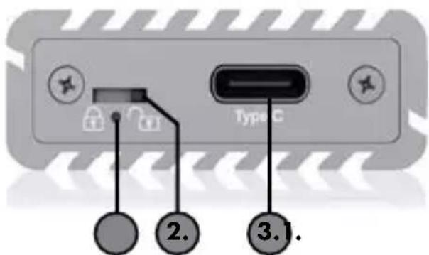
- LED for power and write protection status
- Switch for write protection activation
- USB 3.2 Gen 2 Type-C ^® interface to host connection
Important product information
Dear customer,
please note the following information about the compatibility of USB Type-C ^® enclosures and adapters, including this device!
- Your host computer must have a USB Type C® interface.
- The IB-1817Ma-C31 also works with computers and notebooks with USB 3.0/2.0/1.1 Type-A interfaces as long as the appropriate adapter is available.
- The enclosure also works on devices with a Thunderbolt® 3 interface with transfer rates of up to 10 Gbit/s specified by USB 3.2 Gen 2.
- The Type-C® interface can be connected with USB 3.0 or 2.0 standard in some notebooks and computers. The enclosure only supplies the full data transfer rate of up to 10 Gbit/s to USB 3.2 Gen 2 Type-C® interfaces.
- The following operating systems are supported: Windows®, macOS®
Packing content:
1x IB-1817Ma-C31 (drive not included)
1x Type-C ^® to Type-C ^® / Type-A cable
2x Silicon thermal pads (0.75 mm/grey, 1,0 mm/blue)
1x Heat sink
1x Tool for the write protection switch
1x Screw driver
1x Set of screws, 1x Quick installation guide
1x textile pouch
Quick installation guide IB-1817Ma-C31
External Type-C ^® enclosure for M.2 NVMe SSD with write protection
With the help of the external USB 3.1 Type-C® enclosure IB-1817Ma-C31 you can take one NVMe card with you quickly and easily. It allows access to M.2 SSDs of up to 2 TB no matter to which host you connect it. The IB-1817Ma-C31 is compatible with M.2 cards of 30, 42, 60 and 80 mm length, operating system-independent and suitable for a variety of applications such as high-speed storage, cloning a drive or running a mobile operating system.
With the IB-1817Ma-C31, sensitive data can now be protected against changes and released again via a switch. With the practical mini tool supplied and a small hand movement, the switch on the IB-1817Ma-C31 can be moved to the desired position. Click - Safe.
Key features:
• Housing made of high-grade aluminium with innovative heatsink design
- Interface to host computer: USB 3.2 Gen 2 Type-C®, up to 10 Gbit/s
• Supports PCIe 3.0 x2 data transfer rates of up to 1000 megabyte per second
• M-Key socket for NVMe SSDs, 22x 30/42/60/80 mm
- Provides an additional patented heatsink and thermal pad inside
- Activation of the write protection via switch
• LED for power and access
• Supports Windows®, macOS®
Quick installation guide IB-1817Ma-C31
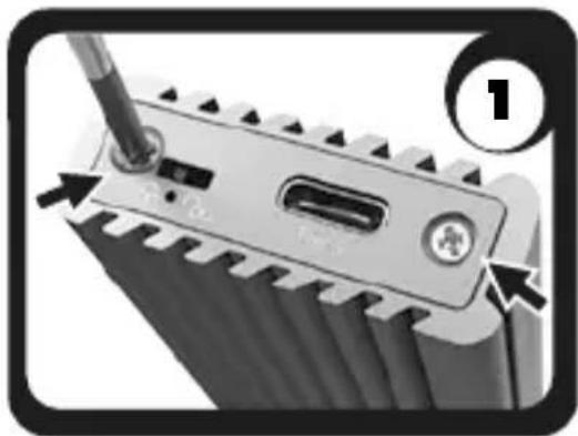
1. Installation
Important: During the drive assembly all cabling has to be disconnected from the computer.
natural_image
Close-up of a mechanical component with a screwdriver inserted, showing teeth and a central slot (no text or symbols visible)- Unscrew the two screws as displayed and open the sidecover.
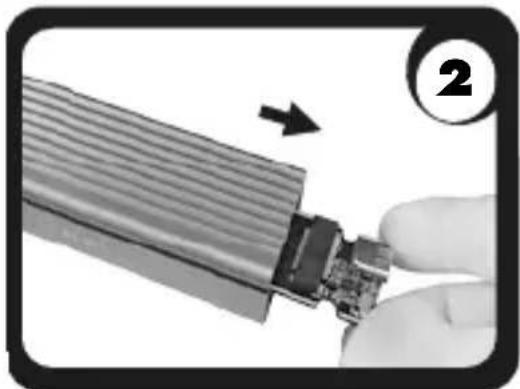
natural_image
Close-up of a hand holding a flexible electronic device with a magnified inset showing internal components (no text or symbols visible)- Take out the PCB.
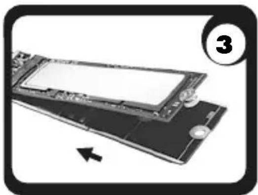
natural_image
Diagram of a computer RAM module with an arrow indicating a component, no text or symbols present- Combine the circular notch of the round M.2 holder with the semi-circular notch of the M.2 SSD and hold it with one finger (the thinner side upwards). Insert your SSD carefully with the connection side into the M.2 socket at an angle of about 30^ so it fits in smoothly.
natural_image
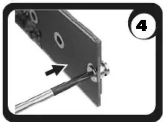
Close-up of a mechanical component with a tool inserted, showing a bolt and wire (no text or symbols visible)- Then push the SSD card down and fix the M.2 nut with the screw as displayed.
Quick installation guide IB-1817Ma-C31
natural_image
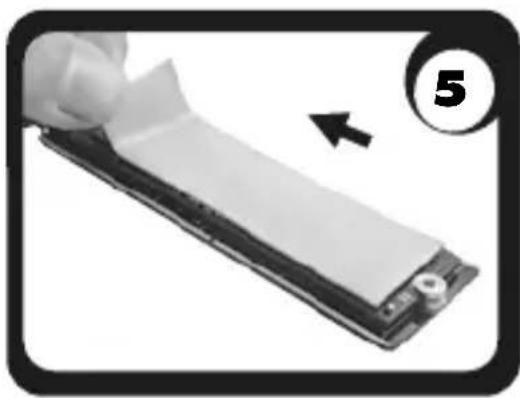
Close-up of a hand holding a white strip on a device, with a numbered circle and arrow indicating direction (no text or symbols)- Place the delivered thermal pad directly on the M.2 NVMe SSD. To get in close contact with the enclosure for an optimal heat dissipation, please use the right thermal pad accordingly to your available M.2 NVMe SSD.
- 0,75 mm/grey for thicker SSDs
- 1,0 mm/blue for thinner SSDs
natural_image
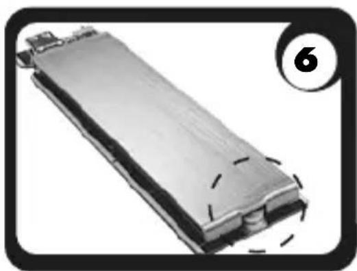
Close-up of a metallic cylindrical component with dashed markings, no visible text or symbols- Put the heatsink on the thermal pad and align the notch to the screw nut.
natural_image
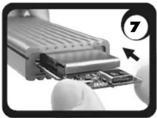
Close-up of hands inserting a circuit board into a device (no visible text or symbols)- Install the PCB back into the track inside the housing. Pay attention to the correct alignment!
natural_image
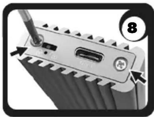
Close-up of a screwdriver inserted into a battery pack (no text or symbols visible)- Install the cover and fasten two screws. Please make sure the write protection switch is placed in the square hole when installing the cover.
Note! Change the write-protect mode before connecting to computer*
Quick installation guide IB-1817Ma-C31
2. Usage
- Connect the IB-1817Ma-C31 via the delivered cable to the corresponding port of your host computer.
- When the IB-1817Ma-C31 has been plugged correctly the LED will turn on white!
- As soon as the write protection has been activated by switch, the LED lights up red*
*Important! A change of the write-protect mode will only be activated when the device has been disconnected and then reconnected to the host computer.
3. Application
Drives must be initialized and have active partitions to be immediately recognized as volumes in the operating system. If this is not the case, initialize the drives in the volume management of your operating system.
- The external drive can be connected to or disconnected from the computer via USB cable without shutting down the computer.
- Please await the end of read/write operations before disconnecting the drive to avoid data loss.
The full USB 3.2 Gen 2 transfer rate can only be achieved with a compatible USB 3.2 Gen 2 host computer. Furthermore, the USB 3.1 drivers must be installed by the operating system. If this is not the case, install the appropriate drivers for your operating system (Windows ^® , macOS ^® ).
For more information, please visit www.icybox.de.
natural_image
Close-up of a screwdriver inserted into a mechanical component, showing teeth and internal structure (no text or symbols)natural_image
Close-up of a hand holding a flexible cable with an internal component, showing a directional arrow (no text or symbols visible)natural_image
Diagram of a computer motherboard with an arrow indicating a component, no text or symbols presentnatural_image
Close-up of a mechanical component with a tool inserted, showing a bolt and screw assembly (no text or symbols visible)natural_image
Close-up of a hand holding a white strip on a device, with a numbered circle and arrow indicating direction (no text or symbols)natural_image
Exterior view of a battery pack with dashed lines indicating internal structure (no text or symbols)natural_image
Close-up of hands inserting a component into a device, with a numbered callout (7) and an arrow indicating direction (no text or symbols on the device itself)natural_image
Close-up of a screwdriver inserted into a battery pack with a plug, showing mechanical components and an arrow indicating direction (no text or symbols)© Copyright 2022 by RaidSonic Technology GmbH. All Rights Reserved
The information contained in this manual is believed to be accurate and reliable. RaidSonic Technology GmbH assumes no responsibility for any errors contained in this manual. RaidSonic Technology GmbH reserves the right to make changes in the specifications and/or design of the above mentioned product without prior notice. The diagrams contained in this manual may also not fully represent the product that you are using and are there for illustration purposes only. RaidSonic Technology GmbH assumes no responsibility for any differences between the product mentioned in this manual and the product you may have.
Brand : Icy Box
Model : IB-1817MA-C31
Category : External hard drive