
AquaEdge 23XRV - Compressor CARRIER - Free user manual and instructions
Find the device manual for free AquaEdge 23XRV CARRIER in PDF.


| Product Type | Centrifugal Compressor (for AquaEdge 23XRV Chiller) |
| Model | AquaEdge 23XRV |
| Brand | Carrier |
| Compressor Type | Semi-hermetic centrifugal |
| Motor Drive | Unit-mounted Variable Frequency Drive (VFD) |
| VFD Manufacturer | Danfoss VLT FC102 series |
| Supply Voltage | 380-480 V AC, 3-phase, 50/60 Hz |
| VFD Power Range | 200 to 1000 kW (drive ratings N200 to N1M0) |
| Max Output Current (VFD) | Up to 1670 A (parallel drive configuration) |
| Enclosure Protection | IP54 (NEMA 12) for D and E sizes; IP00 for parallel drive modules |
| VFD Weight (D size) | 135-275 lb (62-125 kg) |
| VFD Weight (E size) | 650-700 lb (295-318 kg) |
| VFD Weight (PD size enclosure) | Approx. 3000 lb (1361 kg) |
| Safety Features | Lockout/tagout, DC bus capacitor discharge, Safe Torque Off (STO), ESD precautions |
| Commissioning | Verify VFD parameters against chiller nameplate; check power wiring and grounding |
| Maintenance | Periodic inspection of valves, fittings, piping for corrosion/leaks; static test of power modules |
| Repair Parts | Use only Carrier or Danfoss approved replacement parts |
| VFD Cooling | Air-cooled with fans (heat sink) |
| Operating Ambient Temp | Max 40°C (104°F) standard, up to 55°C (131°F) with derating |
| Short Circuit Capacity | 100 kA at 380-480 V (UL) |
| VFD Frame Sizes | D (DD395-DD588), E (DE658-DE990), PD (DP1120-DP1670) |
| Communication Protocol | LEN (Local Equipment Network) via RS-485, PIC6 HMI interface |
| Required Manuals | Danfoss VLT FC102 manual, Carrier 19XR/19MV start-up and troubleshooting manuals |
Frequently Asked Questions - AquaEdge 23XRV CARRIER
User questions about AquaEdge 23XRV CARRIER
0 question about this device. Answer the ones you know or ask your own.
Ask a new question about this device
Download the instructions for your Compressor in PDF format for free! Find your manual AquaEdge 23XRV - CARRIER and take your electronic device back in hand. On this page are published all the documents necessary for the use of your device. AquaEdge 23XRV by CARRIER.
USER MANUAL AquaEdge 23XRV CARRIER
Failure to follow these procedures may result in personal injury or death.
DO NOT work on high-voltage equipment unless you are a qualified electrician.
DO NOT WORK ON electrical components, including control panels, switches, VFD, or oil heater until you are sure ALL POWER IS OFF and no residual voltage can leak from capacitors or solid-state components.
LOCK OPEN AND TAG electrical circuits during servicing. IF WORK IS INTERRUPTED, confirm that all circuits are de-energized before resuming work.
AVOID SPILLING liquid refrigerant on skin or getting it into the eyes. USE SAFETY GOGGLES. Wash any spills from the skin with soap and water. If liquid refrigerant enters the eyes, IMMEDIATELY FLUSH EYES with water and consult a physician.

WARNING
DO NOT USE TORCH to remove any component. System contains oil and refrigerant under pressure.
To remove a component, wear protective gloves and goggles and proceed as follows:
a. Shut off electrical power to unit.
b. Recover refrigerant to relieve all pressure from system using both high-pressure and low pressure ports.
c. Traces of vapor should be displaced with nitrogen and the work area should be well ventilated. Refrigerant in contact with an open flame produces toxic gases.
d. Cut component connection tubing with tubing cutter and remove component from unit. Use a pan to catch any oil that may come out of the lines and as a gauge for how much oil to add to the system.
e. Carefully un-sweat remaining tubing stubs when necessary. Oil can ignite when exposed to torch flame.
Failure to follow these procedures may result in personal injury or death.

WARNING
DO NOT ATTEMPT TO REMOVE fittings, covers, etc., while chiller is under pressure or while chiller is running. Be sure pressure is at 0 psig (0 kPa) before breaking any refrigerant connection.

CAUTION
USE only repair or replacement parts that meet the code requirements of the original equipment.
PERIODICALLY INSPECT all valves, fittings, and piping for corrosion, rust, leaks, or damage.
DO NOT re-use compressor oil or any oil that has been exposed to the atmosphere. Dispose of oil per local codes and regulations.
DO NOT leave refrigerant system open to air any longer than the actual time required to service the equipment. Seal circuits being serviced and charge with dry nitrogen to prevent oil contamination when timely repairs cannot be completed.

CAUTION
Failure to follow these procedures may result in personal injury or damage to equipment.
TO AVOID an electric shock hazard, verify that the voltage on the bus capacitors has discharged completely before servicing. Check the DC bus voltage at the power terminal block by measuring between the +DC and -DC terminals, between the +DC terminal and the chassis, and between the -DC terminal and the chassis. The voltage must be zero for all 3 measurements.
THE USER is responsible to conform with all applicable local, national, and international codes. Failure to observe this precaution could result in damage to, or destruction of, the equipment.
THIS DRIVE contains ESD (electrostatic discharge) sensitive parts and assemblies. Static control precautions are required when installing, testing, servicing or repairing this assembly. Component damage may result if ESD control procedures are not followed. Typical ESD protections are ESD mat and grounded wrist strap.
DO NOT alter the setting of any jumper. Failure to observe this precaution could result in damage to, or destruction of, the equipment.
USE OF power correction capacitors on the output of the drive can result in erratic operation of the motor, nuisance tripping, and/or permanent damage to the drive. Remove power correction capacitors before proceeding. Failure to observe this precaution could result in damage to, or destruction of, the equipment.
MOST CODES require that upstream branch circuit protection be provided to protect input power wiring.
DO NOT route signal and control wiring with power wiring in the same conduit. This can cause interference with drive operation. Failure to observe this precaution could result in damage to, or destruction of, the equipment.
DISTRIBUTION SYSTEM short circuit capacity shall not exceed the rating of the drive. Failure to observe this precaution could result in damage to, or destruction of, the equipment.
DO NOT STEP on refrigerant lines. Broken lines can whip about and release refrigerant, causing personal injury.
DO NOT climb over a chiller. Use platform, catwalk, or staging. Follow safe practices when using ladders.
USE MECHANICAL EQUIPMENT (crane, hoist, etc.) to lift or move inspection covers or other heavy components. Even if components are light, use mechanical equipment when there is a risk of slipping or losing your balance.
BE AWARE that certain automatic start arrangements CAN ENGAGE THE VFD, TOWER FAN, OR PUMPS. Open the disconnect ahead of the VFD, tower fans, or pumps.
INTRODUCTION
The Carrier VFD option Start-Up and Service Manual is intended for trained and qualified service personnel and is to be used during start-up, operation, and maintenance of Danfoss VLT FC102 series drives.
ABBREVIATIONS AND EXPLANATIONS
Frequently used abbreviations in this manual include:
DC — Direct Current
HMI — Human Machine Interface
IGBT — Insulated Gate Bipolar Transistor
I/O — Inputs/Outputs
IP — Internet Protocol
LCP — Local Control Panel
LEN — Local Equipment Network
MCB — Main Control Board
MDCIC — Multi-Drive Control Interface
MOV — Metal Oxide Varistor
PCB — Printed Circuit Board
PE — Protective Earthing Conductor
PIC — Product Integrated Control
PWM — Pulse Width Modulation
STO — Safe Torque Off
VFD — Variable Frequency Drive
Required Publications
The Carrier VFD option Start-Up and Service Manual must be used with the following manuals:
- Latest version of the Danfoss VLT FC102 and VLT parallel AC Drives manuals as applicable.
- Latest revision of the Start-Up, Operation, and Maintenance Instructions for the 19XR with PIC6 Controls.
- Latest revision of the Controls Operation and Troubleshooting manual for 19XR with PIC6 Controls.
Getting Assistance from Danfoss
For technical support on drives, contact Technical Support experts: 1-888-Danfoss (1-888-326-3677).
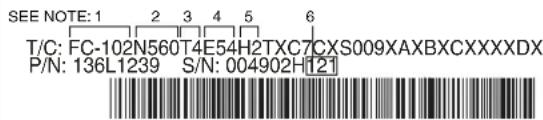
Before calling, have the following information available. Type Code and Serial Number can be found on the Danfoss data nameplate. See Fig. 1.
• Image of drive nameplate including:
Carrier VFD Code (Carrier Part Number)
Danfoss Part Number / Type Code (T/C)
Danfoss Serial Number (S/N)
- Images of cable connections, filters, resistors, fuses, chokes, etc.
• Alarms/warnings experienced
• MCT 10 *.ssp file
For detailed repair procedures, refer to Danfoss VLT Drive Service Manual MG94A502.
Carrier P/N:
560 kW / 750 HP
_IN: 3x380-480V 50/60Hz 954/858A
'LOUT: 3x0-Vin 0-590Hz 990/890A
Type 12 / IP54 Tamb. 40°C/104°F
Max Tamb. 55°C/131°F w/Output Current Derating
SCCR 100 kA at UL Voltage range 380-480V
Danfoss A/S
6430 Nordborg, Denmark
danfoss.com
Assembled by Danfoss for Carrier
ASSEMBLED IN USA

36UO E70524 IND. CONT. EQ.
UL Voltage range 380-480V


DANGER
See manual for special condition / mains fuse
- Identifies product group and drive series. This should always start with FC102.
- Drive Power Rating (N200, N250, N315, N355, N400, N450, N500, N560, N630, N710, N800, N1M0).
- Voltage Rating (T4 = 380-480V AC).
- Enclosure Type: E54: IP54 (NEMA 12).
- Drive type (H=6-pulse drive with RFI filter, P2=6-pulse parallel drive with RFI filter).
- S/N contains information related to Build date after the capital letter (wwy, where ww is the week and y is the year; for example, 121 = week 12, 2021.
- IN = input voltage; OUT = output voltage.
- Danger Electrical Symbol; 40 min indicates that for this size drive the internal capacitors will have discharged 40 minutes after power has been removed from the drive.
Fig. 1 — Sample Danfoss VFD Nameplate
IDENTIFYING DRIVE COMPONENTS
Chiller control, VFD Power Assembly and VFD schematics are included in Appendix A.
WARNING
DC bus capacitors retain hazardous voltages after input power has been disconnected. After disconnecting input power, wait the time specified in Table 1 or as specified on the Danfoss VFD nameplate for the DC bus capacitors to discharge. Always check the voltage with a voltmeter rated for the DC bus voltage to ensure the DC bus capacitors are discharged before touching any internal components. For parallel drive modules (N630 and larger) check voltage before and after the individual DC fuses. Failure to observe these precautions could result in severe bodily injury or loss of life.
An isolated multimeter with diode tester is needed to measure DC bus voltage and to make resistance and diode checks.
Table 1 — Discharge Time
| VFD FRAME | DANFOSS POWER MODULE SIZE | CAPACITOR DISCHARGE TIME (MIN) |
| DD395-DD588 D | 2 0 | |
| DE658-DE990 E | 4 0 | |
| DP1120-DP1670 D | 2 0 |
The Danfoss VFD offering has a passive rectifier section and a six pulse inverter section. For Danfoss VFD frames DD and DE, chiller topology offering consists of a VFD power panel and a separate Danfoss drive mounted on the chiller condenser. The VFD power panel contains the required integration components for the VFD to operate with the chiller system. These components consist of the main circuit breaker, oil pump breaker and terminal block feed to power panel, terminal blocks, control power circuit breaker, control transformers, heater power terminal block feed, and fan relays.
The larger Danfoss DP frame size is used for multiple power modules to be used in parallel. The drive modules and the VFD power panel components are consolidated into a common enclosure.
The Danfoss VFD offering includes optional protective MOVs for VFD electrical surge protection and volt and ammeter options along with a line reactor offering. The drive is offered with no local control panel (LCP) keypad, and therefore if programming is required, a version of Danfoss' MCT-10 will need to be installed
on a laptop. For details of MCT-10, see Danfoss published literature VLT ^1 Motion Control Tools MCT 10 Setup Software Operating Instructions. Note that a keypad is required for some service functions such as enabling LEN on a non-Carrier configured Danfoss type code. (LEN is configured default on a Carrier type code.) A keypad is also required if a drive power card is being replaced.
WARNING
Electrical shock can cause personal injury and death. Shut off all power to this equipment during installation and service. There may be more than one disconnect switch. Tag all disconnect locations to alert others not to restore power until work is completed.
Refer to Fig. 2 for lockout/tagout details.
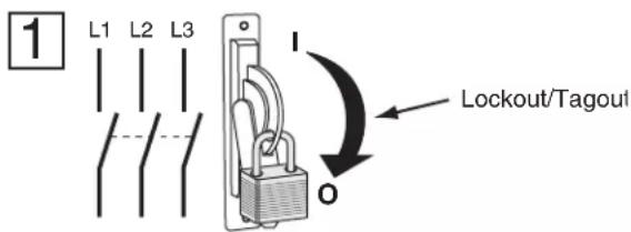
Fig. 2 — Lockout/Tagout
When there is a need to access the VFD enclosure to do any troubleshooting, it is important to identify the type of drive prior to initiating any work.
The Carrier FC102 Danfoss product offering consists of three main configurations: D size, E size, and D size parallel drive (PD) modules. See details for the D size drive in Fig. 3, for the E size drive in Fig. 4, for 19MV size D/E drives see Fig. 5, and for the D size parallel drive modules in Fig. 6. The product range covers a drive range of 200 to 1000 kW. When any work or troubleshooting is required, it is critical to determine the type of drive since their design layouts vary. This can be done by locating the Carrier VFD label located on the outside of the drive or the Danfoss type code on the Danfoss VFD nameplate and matching up the appropriate VFD Power Rating in Table 2 and 3 or Table 4.
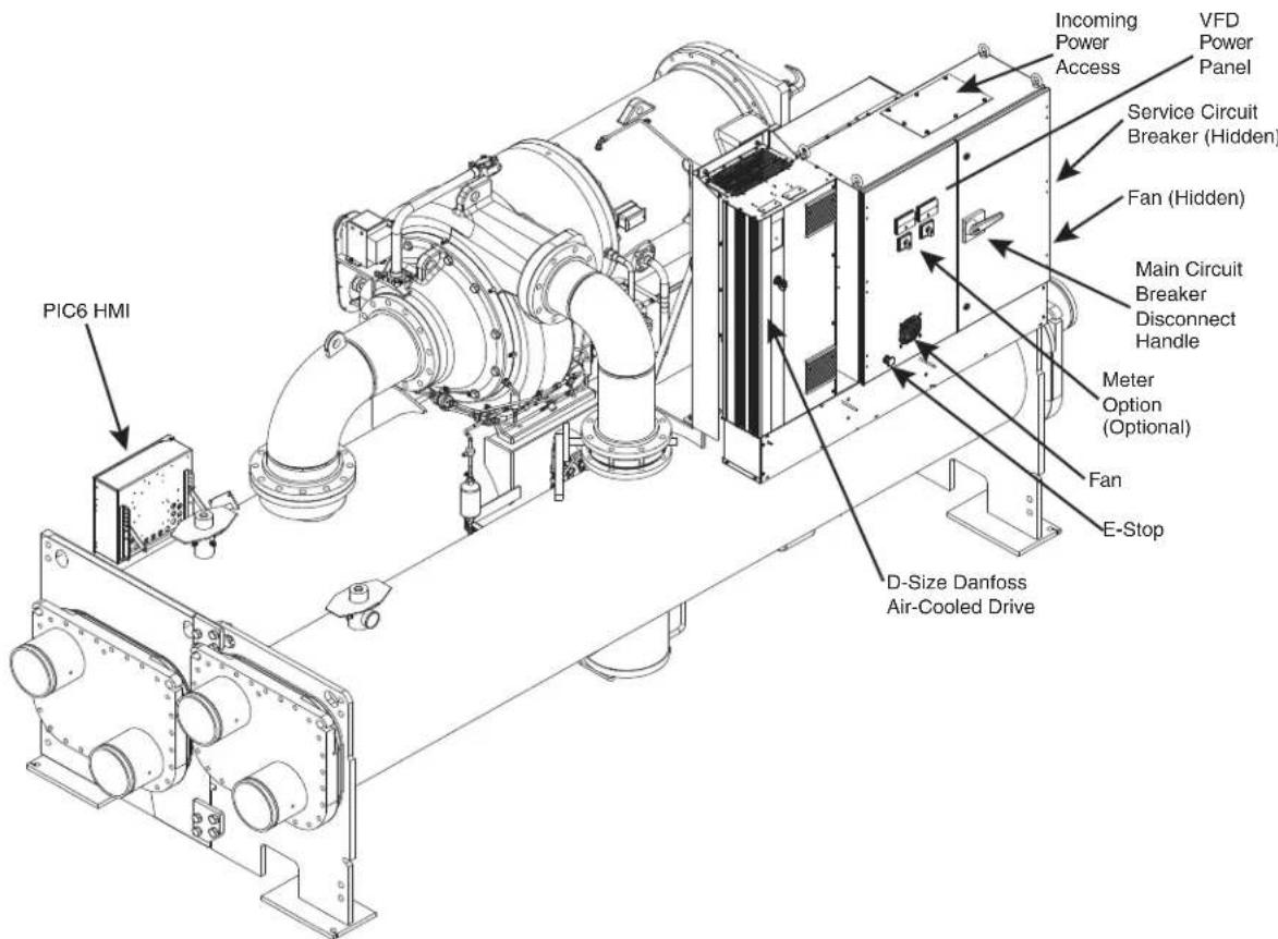
Fig. 3 — D Size Drive — 19XRV
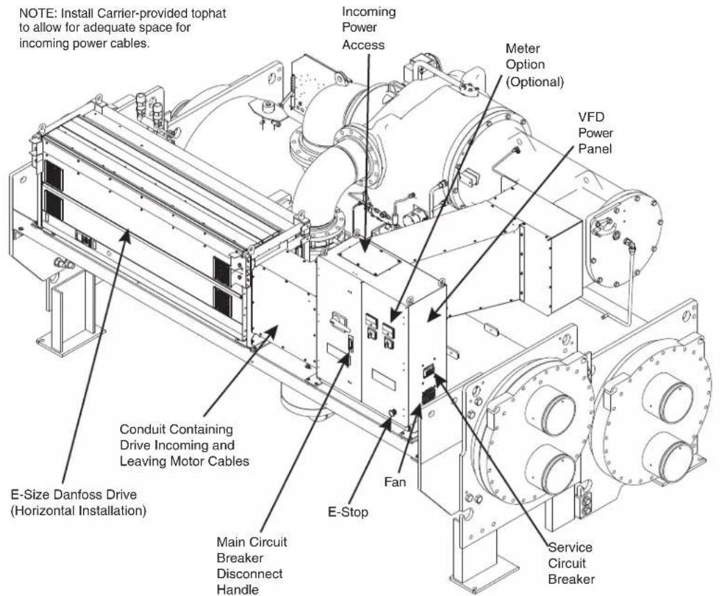
Fig. 4 — E Size Drive — 19XRV
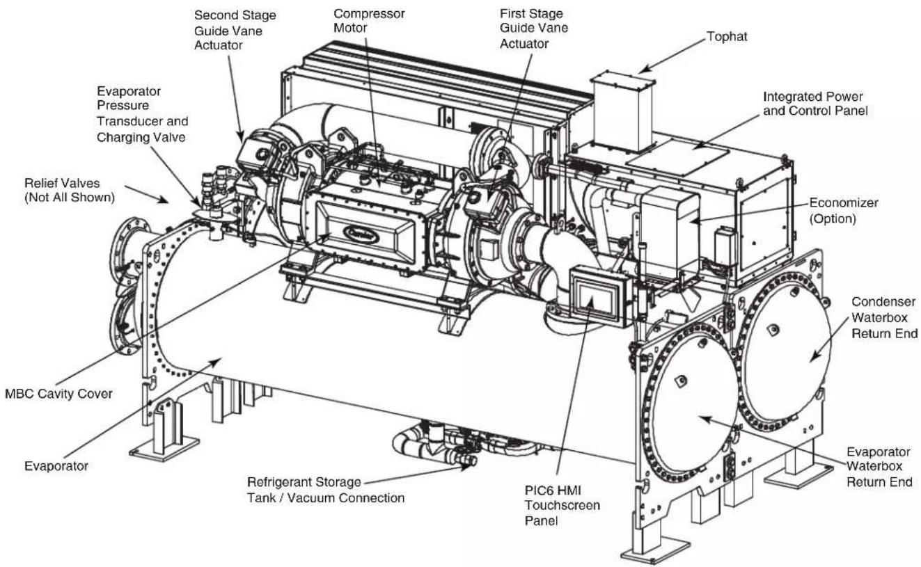
Fig. 5 — D/E Size Drive — 19MV
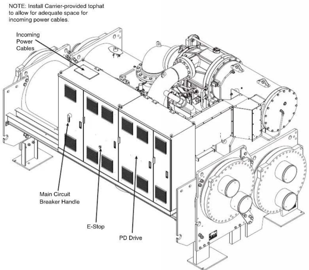
Fig. 6 — Size PD Danfoss Drive (Integrated VFD and VFD Power Panel) — 19XR
Table 2 — VFD Type by Frame Size, D-E
| CARRIER VFD FRAME | DANFOSS | MAX DRIVE ENCLOSURE | DANFOSS DRIVE | ||||
| Type | Enclosure Size | Drive | Weight lb (kg) | HEIGHT in. (mm) | WIDTH in. (mm) | DEPTH in. (mm) | |
| DD395 D D | 2h N200 135 (62) | 43.6 (1107) 12.8 (325) | 14.9 (379) | ||||
| DD480 D D | 2h N250 135 (62) | 43.6 (1107) 12.8 (325) | 14.9 (379) | ||||
| DD558 D D | 2h N315 275 (125) | 43.6 (1107) 12.8 (325) | 14.9 (379) | ||||
| DE658 E1 | E1h N355 650 (295) | 80.4 (2043) 23.7 (602) | 20.2 (513) | ||||
| DE745 E1 | E1h N400 650 (295) | 80.4 (2043) 23.7 (602) | 20.2 (513) | ||||
| DE800 E1 | E1h N450 650 (295) | 80.4 (2043) 23.7 (602) | 20.2 (513) | ||||
| DE880 E2 | E2h N500 700 (318) | 80.4 (2043) 27.5 (698) | 20.2 (513) | ||||
| DE990 E2 | E2h N560 700 (318) | 80.4 (2043) 27.5 (698) | 20.2 (513) | ||||
Table 3 — VFD Power Panel for D and E Size Danfoss Drives
| UNIT | VFD POWER PANEL | |||
| WEIGHTlb (kg) | HEIGHTin. (mm) | WIDTHin. (mm) | DEPTHin. (mm) | |
| 19MV 531 (241) | 28.0 (711) 47.5 (1206) 28.75 (730) | |||
| 19XRV 300 (136) | 40.5 (1030) | 37.25 (950) 19.0 (480) | ||
Table 4 — VFD Type by Frame Size, PD
| CARRIER VFD FRAME | DANFOSS | MAX DRIVE ENCLOSURE | DANFOSS DRIVE | VFD ENCLOSURE | |||||||
| Type | Enclosure Size | Drive | Weight lb (kg) | HEIGHT in. (mm) | WIDTH in. (mm) | DEPTH in. (mm) | WEIGHT lb (kg) | HEIGHT in. (mm) | WIDTH in. (mm) | DEPTH in. (mm) | |
| DP1120 | D Parallel | Da4 | N630 | 275 (125) | 88.7 (2254) | 63.3 (1608) | 25.0 (636) | 3000 (1361) | 65 (1652) | 110 (2800) | 24.6 (625) |
| DP1260 | D Parallel | Da4 | N710 | 275 (125) | 88.7 (2254) | 63.3 (1608) | 25.0 (636) | 3000 (1361) | 65 (1652) | 110 (2800) | 24.6 (625) |
| DP1460 | D Parallel | Da4 | N800 | 275 (125) | 88.7 (2254) | 63.3 (1608) | 25.0 (636) | 3000 (1361) | 65 (1652) | 110 (2800) | 24.6 (625) |
| DP1670 | D Parallel | Da4 | N1M0 | 275 (125) | 88.7 (2254) | 63.3 (1608) | 25.0 (636) | 3000 (1361) | 65 (1652) | 110 (2800) | 24.6 (625) |
NOTE: Weight and dimensions for PD (parallel drive) for the Danfoss power module are for the combined VFD enclosure (both VFD and VFD power panel components).
Rigging
D, E SIZES
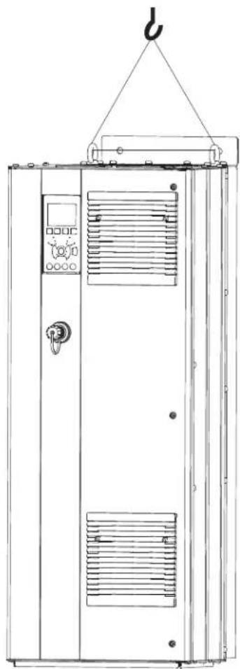
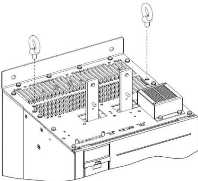
Drive enclosure and associated components are heavy. To avoid injury be sure to use appropriate equipment with appropriate weight ratings for lifting. Always use dedicated lifting eyes for lifting and never walk under suspended load. Wear PPE such as gloves, safety glasses and safety shoes to prevent injury. Ensure correct length of lifting cables so lifting angle is 65 degrees or larger with horizontal (Fig. 7). Always use lifting eye bolts (Fig. 8) to rig drive if it needs to be removed from the chiller. Note that E series drives are placed on the chiller in horizontal position and will need to be rigged from that orientation using rigging eyes in the four corners.
natural_image
Line drawing of an industrial control cabinet with a crane hook above (no text or symbols)Fig. 7 — Lifting Cables
natural_image
Technical line drawing of an electronic device chassis with cooling fans and internal circuitry (no text or labels)Fig. 8 — Installation of Eye Bolts
PARALLEL DRIVE MODULES
Parallel Drive Modules consist of four smaller D size modules installed in parallel configuration.
Install eye bolts and rig individual modules as a D series drive. Note that some component removal is necessary to gain access to remove an individual drive.
If the entire drive module enclosure is to be rigged, use dedicated rigging lugs. Use the 4 rigging lugs located in each corner of the drive enclosure.
The PD enclosure can be lifted by the 4 outside eyebolts. Lifting angle must never be more than a 45 degree pull (Fig. 9). See Fig. 10 for location of eyebolts.
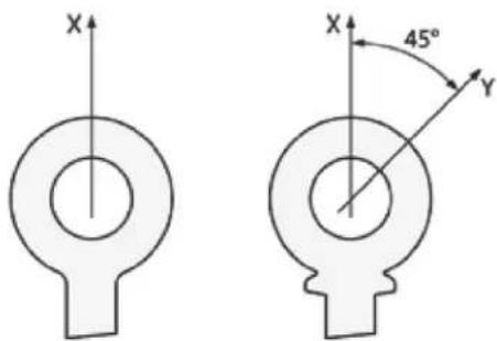
Fig. 9 — Lifting Angle for Eyebolts
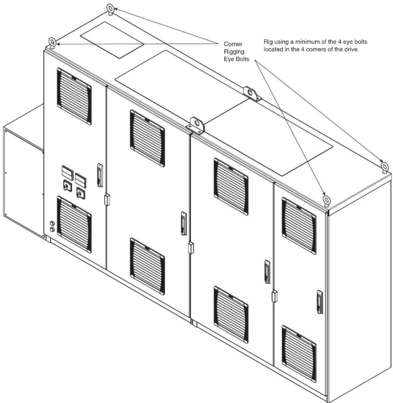
Fig. 10 — Danfoss PD Drive Rigging
Components and Physical Data
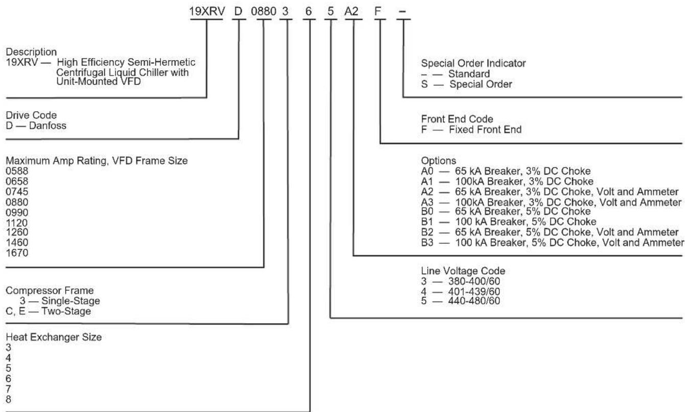
19XRV Carrier Danfoss VFD Part Numbers are structured as shown in Fig. 11. 19MV Carrier Danfoss VFD Part Numbers are
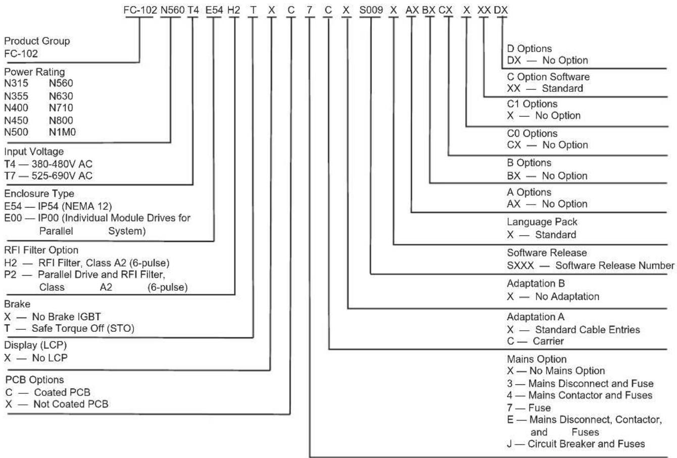
structured as shown in Fig. 12. An example of Danfoss Type Code (TC) Breakdown is shown in Fig. 13.
flowchart
graph TD
    A["19XRV — High Efficiency Semi-Hermetic Centrifugal Liquid Chiller with Unit-Mounted VFD"] --> B["Drive Code D — Danfoss"]
    A --> C["Maximum Amp Rating, VFD Frame Size 0588"]
    A --> D["Compressor Frame 3 — Single-Stage C, E — Two-Stage"]
    A --> E["Heat Exchanger Size 3"]
    A --> F["Line Voltage Code 3 — 380-400/60"]
    A --> G["Options A0 — 65 kA Breaker, 3% DC Choke"]
    A --> H["Options A1 — 100kA Breaker, 3% DC Choke"]
    A --> I["Options A2 — 65 kA Breaker, 3% DC Choke, Volt and Ammeter"]
    A --> J["Options A3 — 100kA Breaker, 3% DC Choke, Volt and Ammeter"]
    A --> K["Options B0 — 65 kA Breaker, 5% DC Choke"]
    A --> L["Options B1 — 100 kA Breaker, 5% DC Choke"]
    A --> M["Options B2 — 65 kA Breaker, 5% DC Choke, Volt and Ammeter"]
    A --> N["Options B3 — 100 kA Breaker, 5% DC Choke, Volt and Ammeter"]
    A --> O["Special Order Indicator — Standard"]
    A --> P["Front End Code F — Fixed Front End"]
    A --> Q["Special Order Indicator — Standard S — Special Order"]
Fig. 11 — Carrier Part Number for 19XRV Danfoss Drive
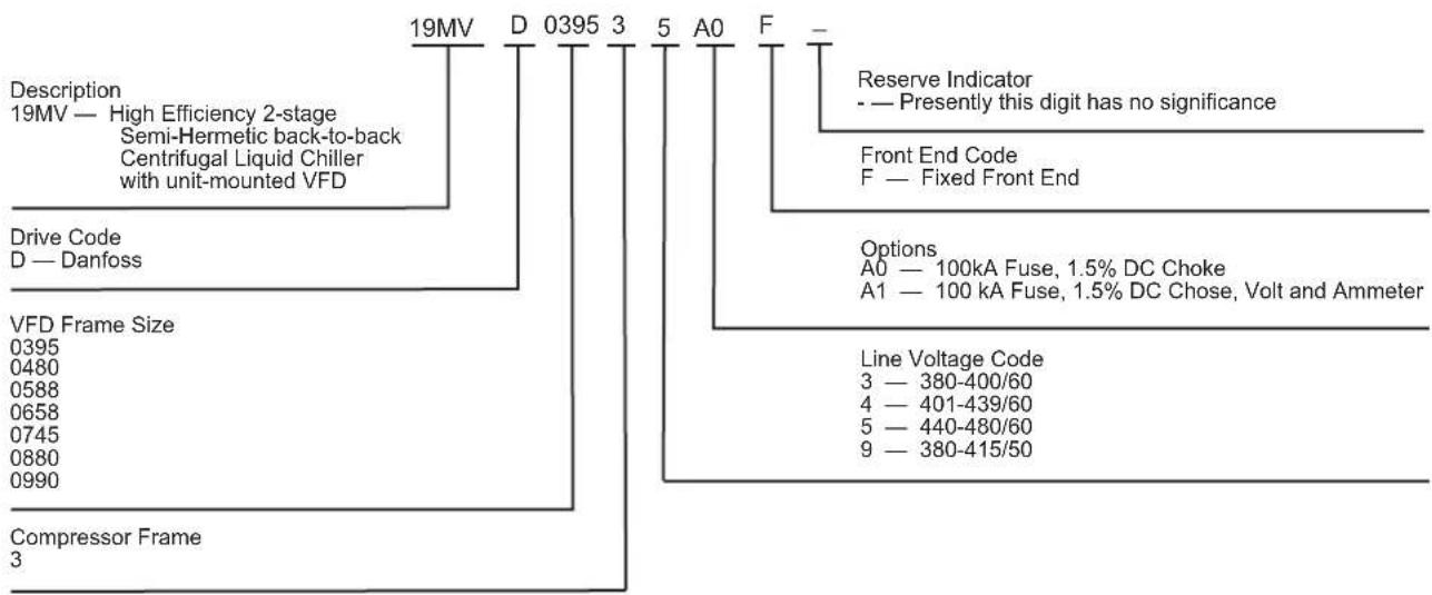
Fig. 12 — Carrier Part Number for 19MV Danfoss VFD
flowchart
graph TD
    A["FC-102"] --> B["Product Group"]
    A --> C["Power Rating"]
    A --> D["Input Voltage"]
    A --> E["Enclosure Type"]
    A --> F["RFI Filter Option"]
    A --> G["Brake"]
    A --> H["Display (LCP)"]
    A --> I["PCB Options"]

    B --> J["FC-102 N560 T4 E54 H2 T X C 7 C X S009 X AX BX CX X XX DX"]
    C --> K["N315 N560"]
    C --> L["N355 N630"]
    C --> M["N400 N710"]
    C --> N["N450 N800"]
    C --> O["N500 N1M0"]

    D --> P["T4 — 380-480V AC"]
    D --> Q["T7 — 525-690V AC"]

    E --> R["E54 — IP54 (NEMA 12)"]
    E --> S["E00 — IP00 (Individual Module Drives for Parallel System)"]

    F --> T["H2 — RFI Filter, Class A2 (6-pulse)"]
    F --> U["P2 — Parallel Drive and RFI Filter, Class A2 (6-pulse)"]

    G --> V["X — No LCP"]

    H --> W["C — Coated PCB"]
    H --> X["X — Not Coated PCB"]

    I --> Y["Mains Option"]
    I --> Z["X — No Mains Option"]
    I --> AA["3 — Mains Disconnect and Fuse"]
    I --> AB["4 — Mains Contactor and Fuses"]
    I --> AC["7 — Fuse"]
    I --> AD["E — Mains Disconnect, Contactor, and Fuses"]
    I --> AE["J — Circuit Breaker and Fuses"]
Fig. 13 — Example of Danfoss Type Code (TC) Breakdown
D Size Drive
The D size FC102 drive and Carrier VFD control panel are positioned side by side off-center on top of the condenser shell.
The Carrier VFD power panel is where the customer runs unit incoming power; the panel contains all required components to interface with the VFD, control panel, and power panel (as applicable). See Fig. 14-16.
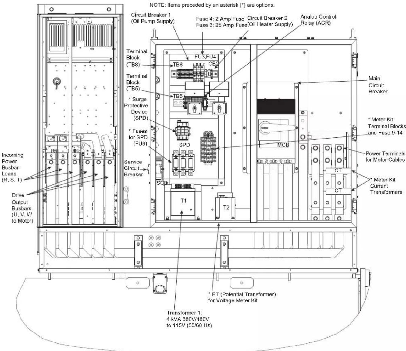
Fig. 14 — D Size FC102 Drive and Carrier VFD Power Panel (19XRV Shown)
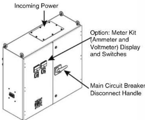
Fig. 15 — Carrier 19XRV VFD Power Panel for D and E Size Drives (19XRV D Size Panel Shown)
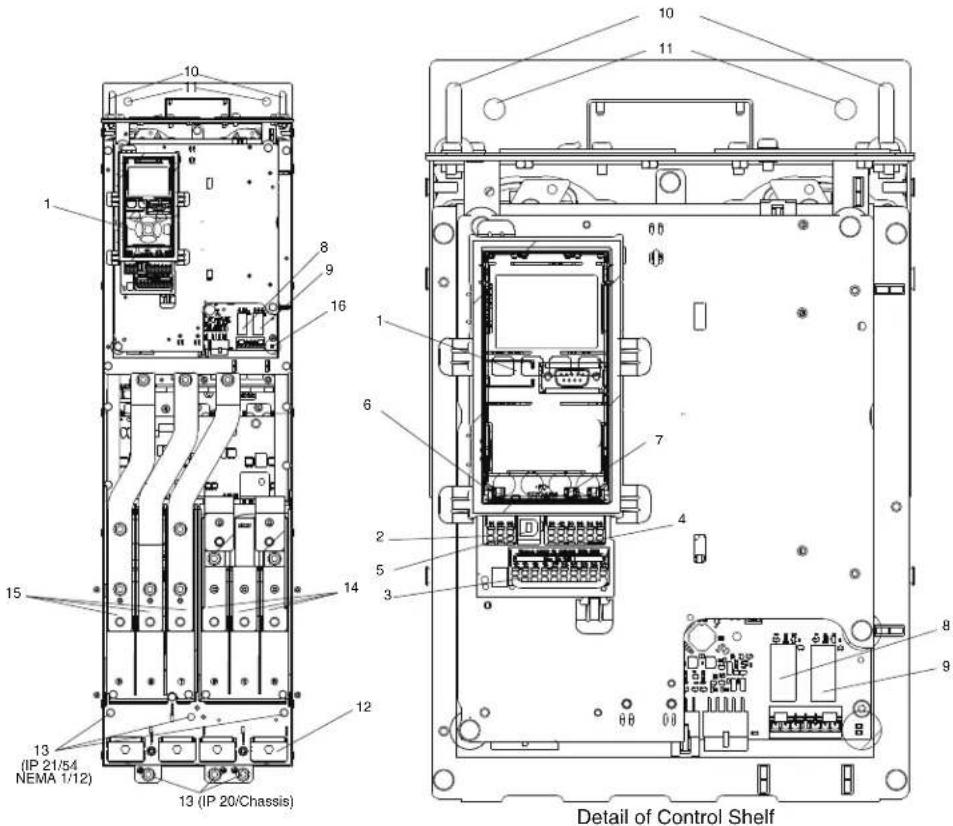
1 LCP (Local Control Panel) — not provided
2 RS-485 Serial Bus Connector
3 Digital I/O and 24V Power Supply
4 Analog I/O Connector
5 USB Connector
6 Serial Bus Terminal Switch
7 Analog Switches (A53), (A54)
8 Relay (01, 02, 03)
9 Relay 2 (04, 05, 06)
10 Lifting Ring
11 Mounting Slot
12 Cable Clamp (PE)
13 Ground
14 Motor Output Terminals
96 (U), 97 (V), 98 (W)
15 Line Power Input Terminals
91 (R), 92 (S), 93 (T)
16 TB5 (IP21/54 only) Terminal block for anti-condensation heater.
Fig. 16 — D Size Control Shelf Components
To check DC bus voltage check voltage between terminal 1 and 2 as depicted below. To reach the DC bus location a voltmeter with safety probe tip extenders must be utilized since the DC bus studs are located far back in the drive. See Fig. 17 and static checks later in this manual.
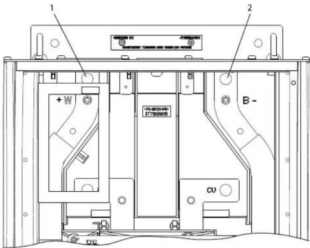
1 DΦ (+) Bus
2 DC (-) Bus
Fasteners are M5 studs.
Fig. 17 — DC Bus Location in D1h–D8h Drives
E Size Drive
The E size FC102 drives have higher amperage capacity compared to the D size. Like the D size, the E size drive is positioned on the condenser in conjunction with the VFD power panel. The E size drives are mounted in horizontal position. The E size drives are mounted on a VFD bracket arrangement supported and suspended between the condenser tubesheets.
For the smaller D size drives, customer incoming power is terminated in the VFD Power Panel; power leads are run from the VFD Power Panel to the VFD and from the VFD to the motor. The main power panel is detailed in Fig. 18-20. For an interior view of the E drive enclosure, see Fig. 21; Fig. 22 details control shelf elements.
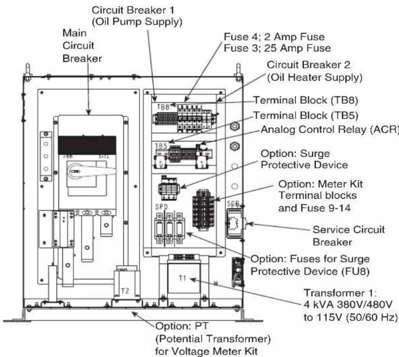
Fig. 18 — 19XRV Main Power Panel (MPP), E Size
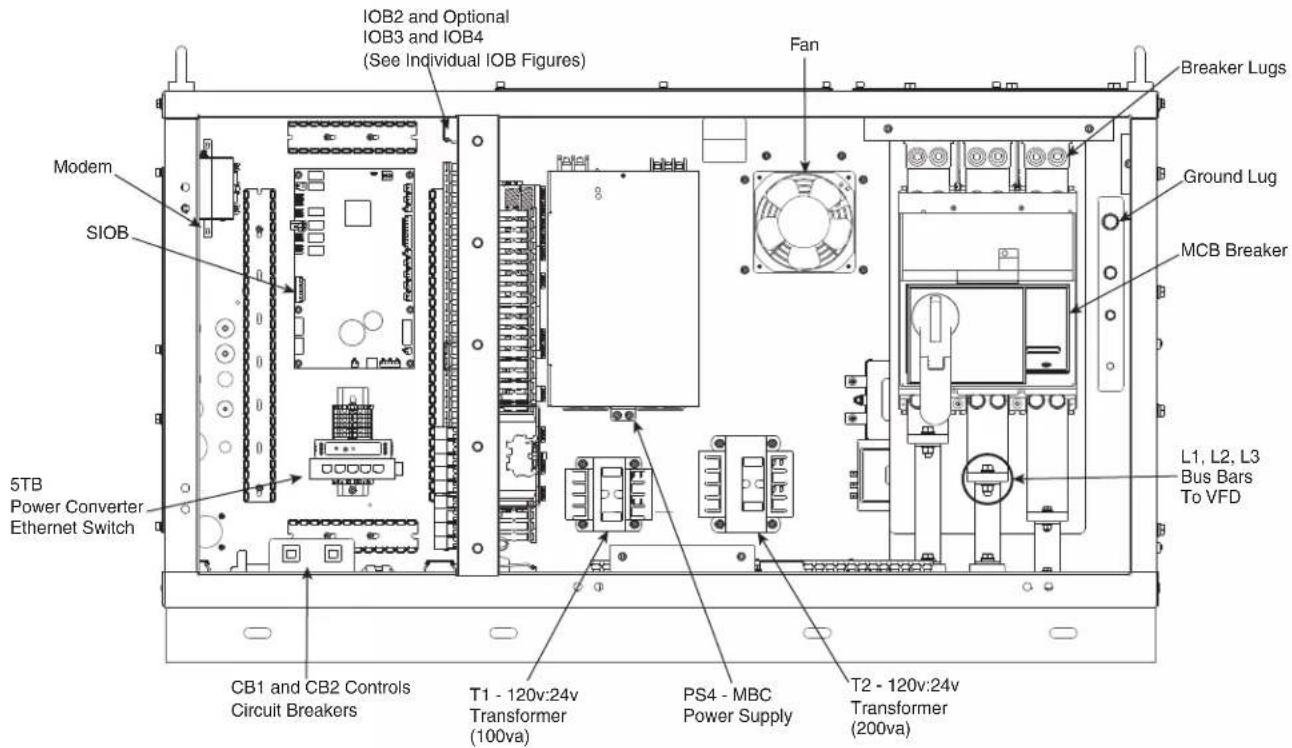
Fig. 19 — 19MV Power Panel - Front View (D and E Size Drive)
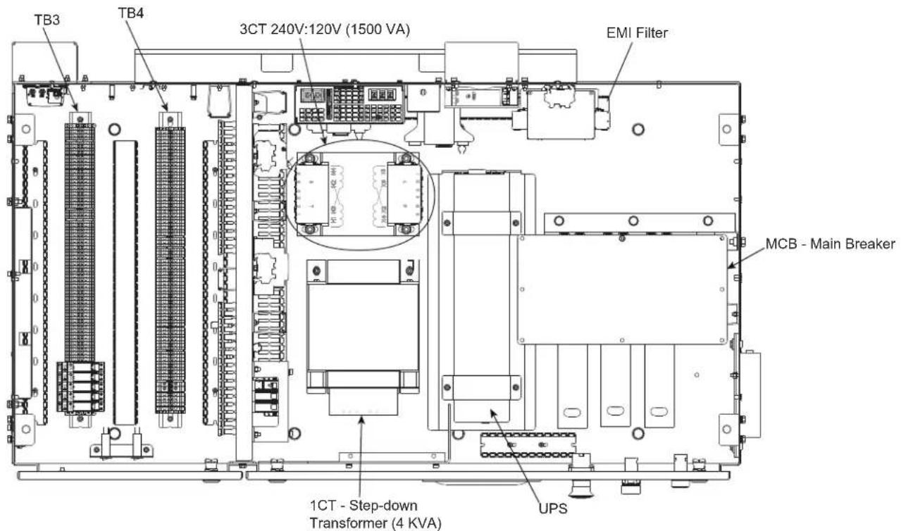
NOTE: Field Wiring Connections Are All on Terminal Blocks TB3 and TB4 (Located on Floor of Low Voltage Section)
Fig. 20 — 19MV Power Panel - Top View (D and E Size Drive)
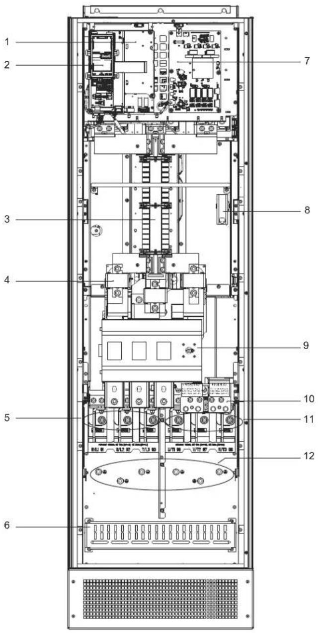
1 Control Shelf
2 Local Control Panel (LCP) cradle
3 RFI Filter (optional)
4 Mains fuses (required for UL compliance, but otherwise optional)
5 Mains Terminal
6 FRI Shield Termination
7 Fan Power Card
8 Space Heater (optional)
9 Mains Disconnect (optional)
10 Brake/Regeneration Terminals (optional)
11 Motor Terminals
12 Ground Terminals
Fig. 21 — Interior View of Enclosures, E Size Drive DE658 through DE990
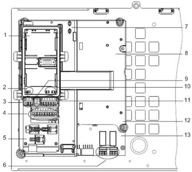
1 LCP Cradle (LCP not shown or provided)
2 Bus Terminal Switch
3 Serial Communication Terminals
4 Digital Input/Output Terminals
5 Cable/EMC Clamps
6 Relay 1 and Relay 2
7 Control Card (underneath LCP and Control Terminals)
8 Control Shelf
9 USB Port
10 Analog Input Switches A53/A54
11 Analog Input/Output Terminals
12 Brake Resistor Terminals, 104-106 (on power card underneath control shelf)
13 Power Card (underneath the control shelf)
Fig. 22 — Control Shelf Details
For static checks an isolated multimeter with diode tester is needed to measure DC bus voltage and to make diode checks. DC+ and DC- terminals are identified in Fig. 23 for E sized drives.
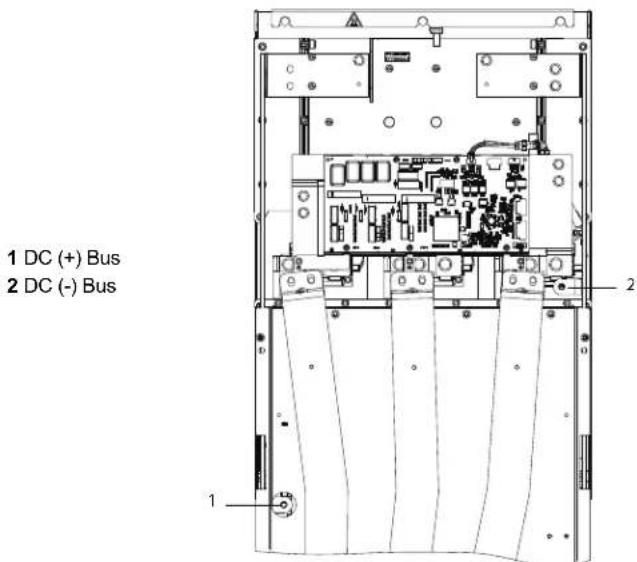
Fig. 23 — DC Bus Location in E1h–E4h Drives, Shown in Upright Position
D and E Size VFD Power Panel Schematics — 19XRV
See Fig. 24 and 25 for detailed drawings.
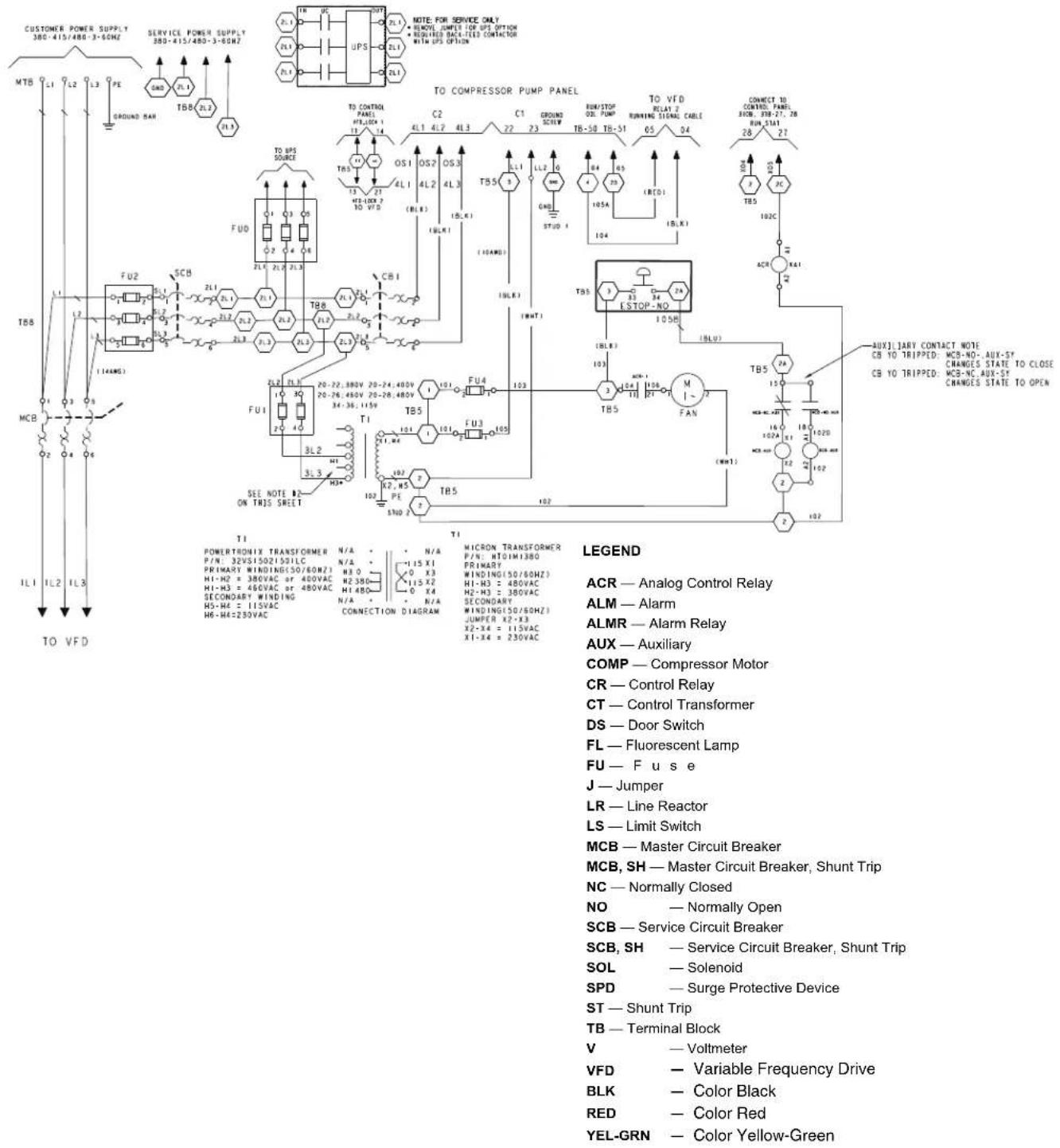
Fig. 24 — Danfoss D and E Size VFD Power Panel Wiring Diagram
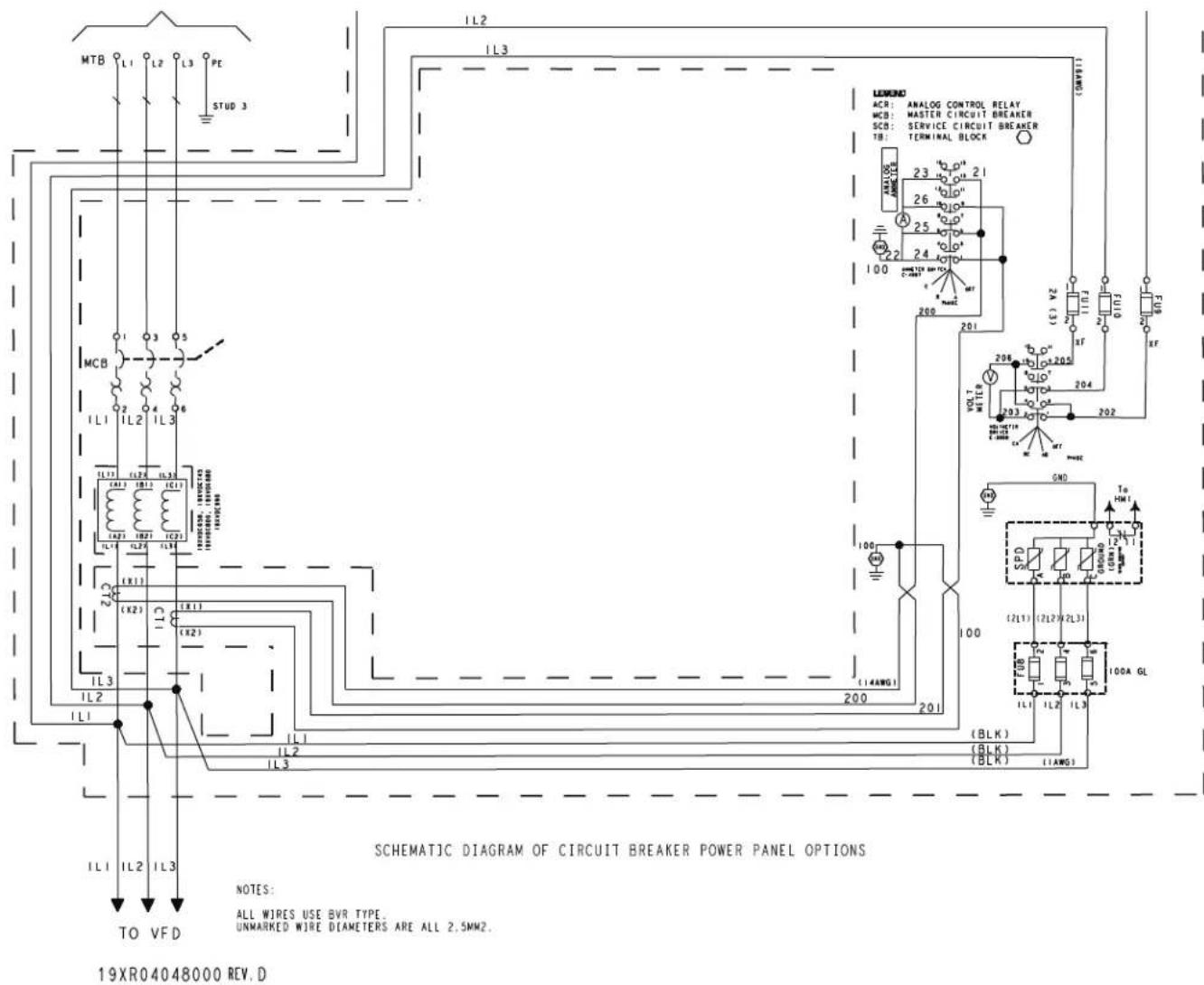
Fig. 25 — Danfoss D and E Size VFD Power Panel Schematic (Ammeter, Voltmeter, and Surge Protective Device Options)
NOTE: See Appendix A for the 19MV controls and power panel wiring diagram. See Appendix A for the 19XR controls and compressor power panel wiring.
PD Size Drive
PARALLEL DRIVE SYSTEMS - DP1120 - DP1670
Parallel drive (PD) systems consist of four D size FC102 drives mounted in a common enclosure, creating a larger PD size with greater ampacity than D and E size drives. As per Table 4 the Carrier PD size drives offering yields a range up to 1670 amp.
The PD size drive enclosure includes both the drive components and the VFD Power Panel components which were separated in its own enclosure for the D and E drive size offering. See Fig. 26-28. NOTE: Enclosure does not represent Carrier application.
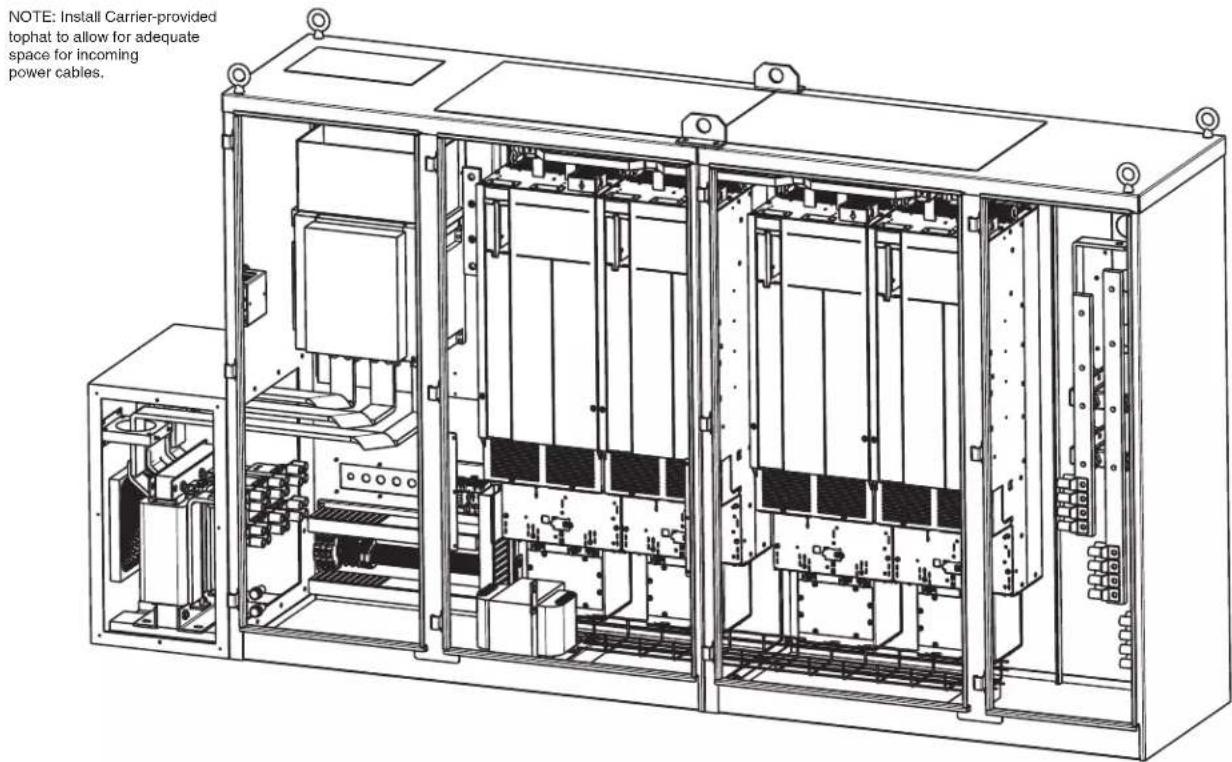
Fig. 26 — Parallel Drive Isometric View
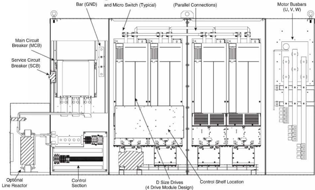
Fig. 27 — Parallel Drive Overall Layout
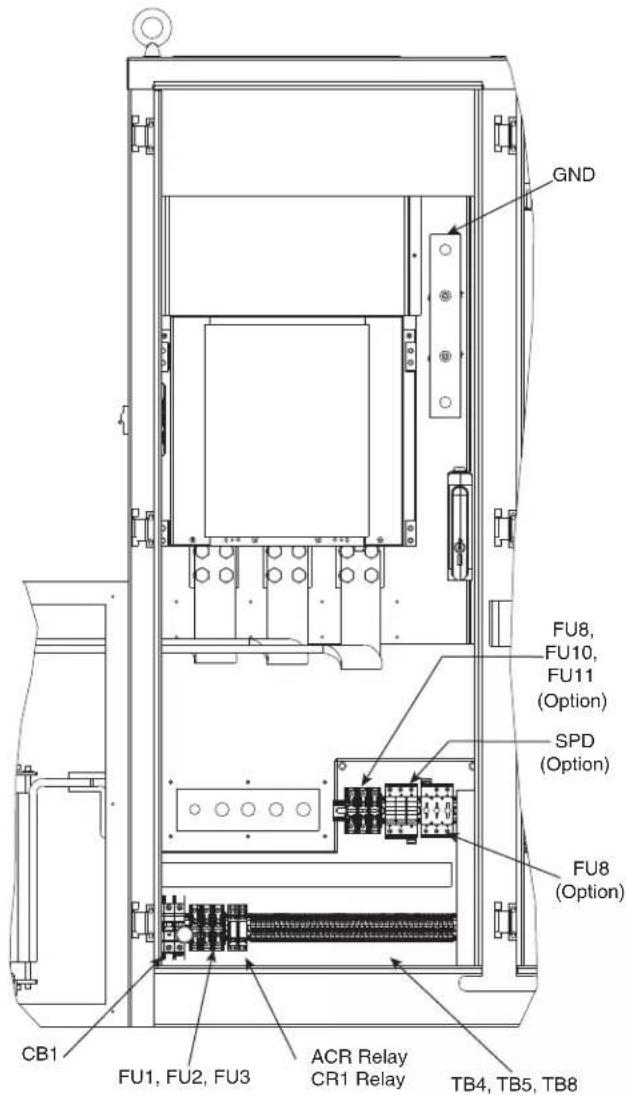
Fig. 28 — Control Section Component Identification
Control Shelf
The control shelf contains the MDCIC (multi-drive control interface card), and control card. The MDCIC is connected to each of the drive modules via a ribbon cable and communicates to the control card. The control card controls the operation of the drive modules. See Fig. 29.
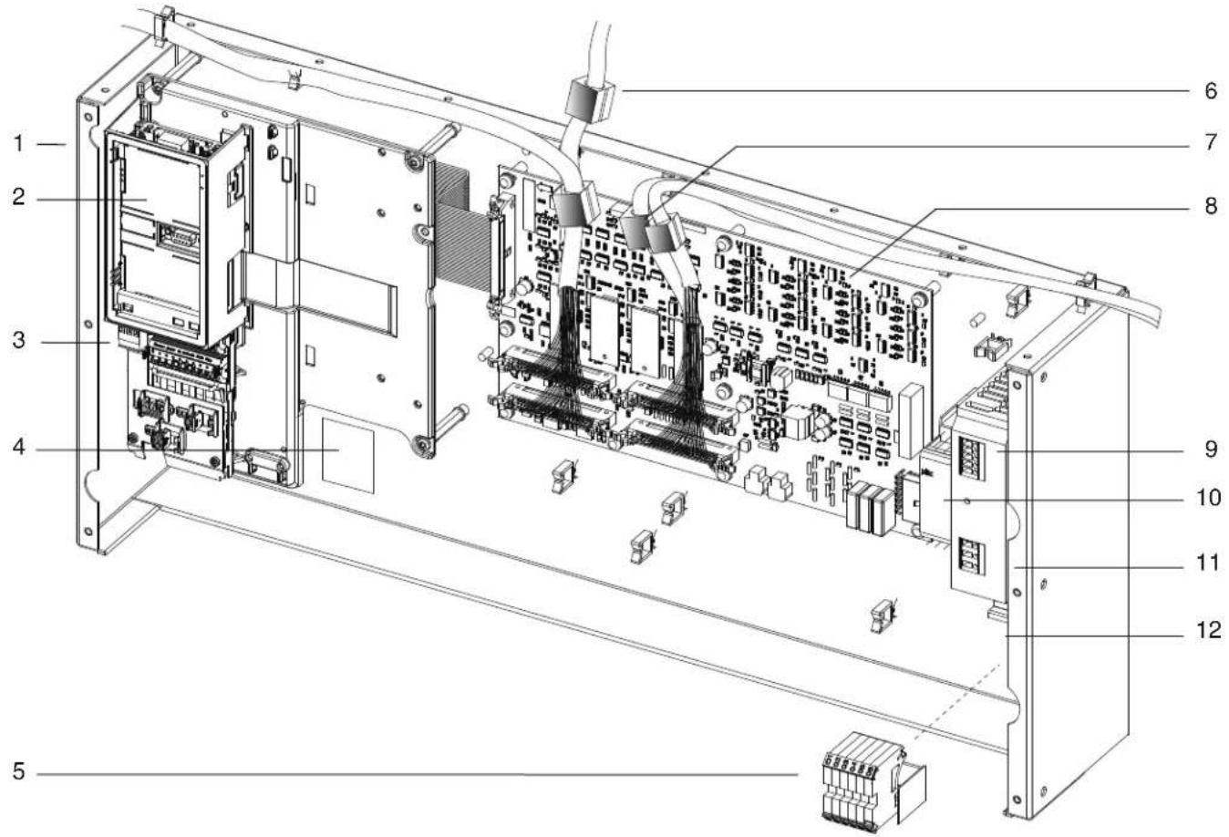
| 1 Control Shelf | Interfaces with, and controls, the various drive system components. Allows connection of an external control device. |
| 2 LCP Cradle | Cradle where the LCP may optionally be installed, but is not provided by factory. |
| 3 Control Terminal Blocks | Terminal blocks for connecting control wiring. |
| 4 Top Level Drive System Label Label describing the drive system at the top-level. | |
| 5 Relay Terminal Blocks | Terminal blocks for connecting the relay cable from the relay connector on the top plate of drive module 1. |
| 6 Ferrite core Reduces high frequency electromagnetic noise. | |
| 7 44-Pin Ribbon Cable Connects the individual drive module with MDCIC. | |
| 8 MDCIC Multi-drive control interface card (MDCIC) with cover plate removed. | |
| 9 SMPS Switched mode power supply | |
| 10 Pilz relay Relay | |
| 11 DIN rail Mounting | |
| 12 Terminal block Mounted on DIN rail | |
Fig. 29 — Control Shelf
PD Module
Each drive module has an IP00 protection rating. Four modules are connected in parallel to create a drive system. See Fig. 30-31. The parallel drive modules contain 2 DC fuses per drive module.
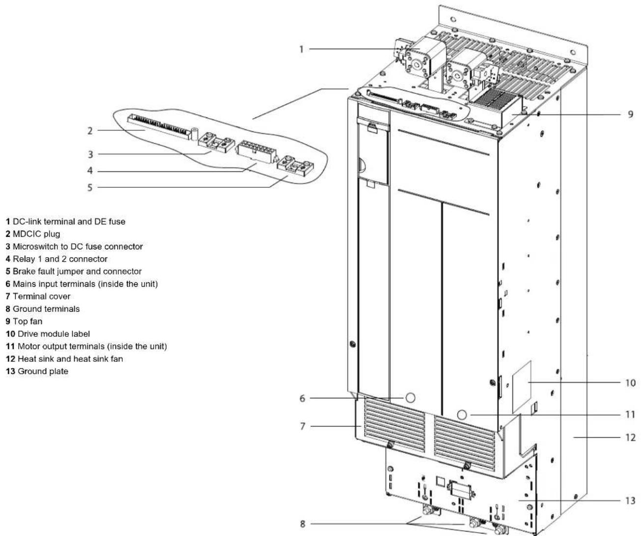
Fig. 30 — View of Parallel Drive Module
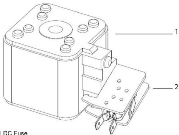
Fig. 31 — DC Fuse and Microswitch Connector
1 DC Fuse
2 Microswitch Connector
DC Bus
When testing parallel drive systems do the following:
- To access the DC bus voltage, use the REGEN terminals at the top of one of the modules.
- When testing DC bus voltage for the entire system, it is not necessary to remove the interlink connections between the individual drives.
- When testing DC bus voltage for an individual drive, the module must be isolated by removing interlink connections and the control cable connections of the module.
For DC bus location, see Fig. 32. For more details, see the PD VFD module wiring schematic (Fig. 33).
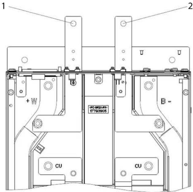
1 DC (+) Bus
2 DC (-) Bus
Fasteners are M5 studs.
Fig. 32 — DC Bus Location in Parallel Drive Systems
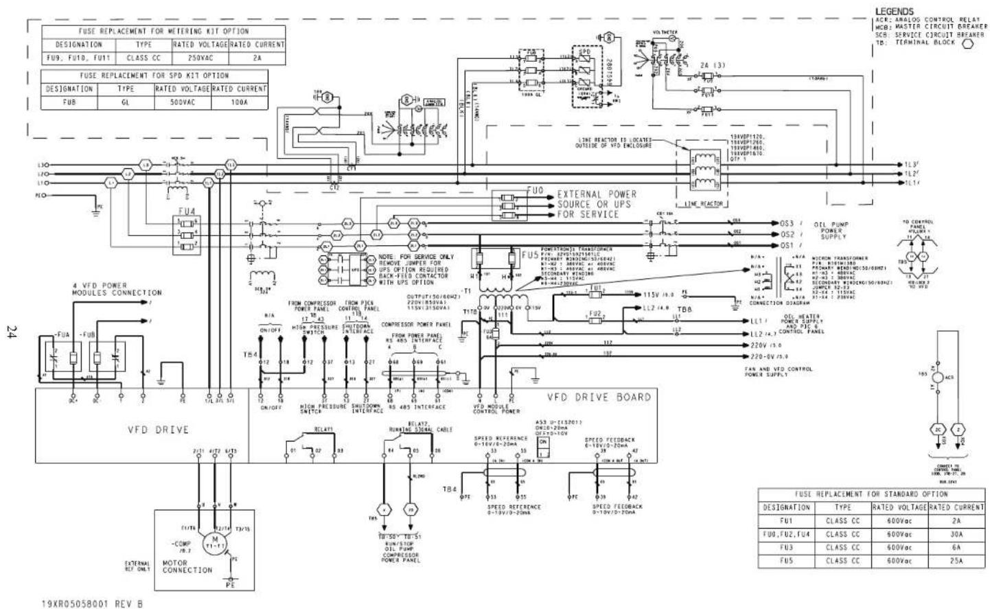
Fig. 33 — Danfoss PD VFD Module Wiring Schematic
START-UP Alternate Wire Lugs
DANGER
Internal components and circuit boards of the drive are live when the drive is connected to incoming power. Coming into contact with this voltage is extremely dangerous and will result in severe personal injury or death.
The motor terminals U, V, W and the DC bus (DC+ and DC-) are live when the drive is connected to incoming power, even if the motor is not running.
Do not make any connections when the drive is connected to the incoming power.
After having disconnected the drive, if any service work is to be performed wait for the capacitors to fully discharge. The minimum waiting time is specified on the drive label.
Prior to performing any repair work measure DC bus voltage with a volt meter. For drives in parallel ensure to measure DC bus voltage before and after the individual DC fuses.
Before connecting the drive to the incoming power, make sure that the enclosure is closed.
WARNING
The control I/O-terminals are isolated from the mains potential. However, the relay outputs and other I/O terminals may have a dangerous control voltage present even when the drive is disconnected from incoming power. Coming into contact with this voltage could result in severe personal injury.
If the incoming power wire size in the VFD power panel does not fit the standard lug, alternate lugs may be available. Please contact the circuit breaker manufacturer for availability. Note that lugs rated for a higher current than the circuit breaker may be used. See Table 5 or 6 for wire lug specifications.
Verify Installation
Record the following job information:
- Job Name
- Job Number
- City
- State
- Zip Code
Record the following nameplate information, it is suggested to take a picture of the appropriate nameplates for future reference.
- From the Danfoss nameplate (Fig. 1) located inside the VFD enclosure:
a. Danfoss Type Code (TC) Number
b. Danfoss Serial Number
- From the machine nameplate (Fig. 34) located on the VFD enclosure:
a. Chiller Serial Number
b. Chiller Model
c. Motor rated load amps
d. Motor nameplate rpm
e. Motor nameplate kW
f. Motor nameplate voltage
g. Voltage
Grounding bar hole size:
DD/DE size 14 mm (0.55 in.)
PD size 18 mm (0.71 in.)
Table 5 — 19XRV Wire Lugs
| VOLTAGE VFD | MAX RATED OUTPUT AMP | BREAKER AMP SIZE | ABB LUG | LUG CABLE RANGE | |
| 380-439V | DD588 | 570 | 800A | 1SDA113095R1 | (3) 2/0-400 kcmil |
| DE658 | 638 | 800A | 1SDA113095R1 | (3) 2/0-400 kcmil | |
| DE745 | 722 | 800A | 1SDA113095R1 | (3) 2/0-400 kcmil | |
| DE800 | 776 | 800A | 1SDA113095R1 | (3) 2/0-400 kcmil | |
| DE880 | 853 | 1000A | 1SDA104758R1 | (4) 4/0-500 kcmil | |
| DE990 | 960 | 1000A | 1SDA104758R1 | (4) 4/0-500 kcmil | |
| DP1120 | 1086 | 1600A | K8TM | (4) 1/0-750 kcmil | |
| DP1260 | 1222 | 1600A | K8TM | (4) 1/0-750 kcmil | |
| DP1460 | 1416 | 2000A | K8TM | (4) 1/0-750 kcmil | |
| DP1670 | 1619 | 2000A | K8TM | (4) 1/0-750 kcmil | |
| 440-480V | DD588 | 518 | 800A | 1SDA113095R1 | (3) 2/0-400 kcmil |
| DE658 | 572 | 800A | 1SDA113095R1 | (3) 2/0-400 kcmil | |
| DE745 | 658 | 800A | 1SDA113095R1 | (3) 2/0-400 kcmil | |
| DE800 | 708 | 800A | 1SDA113095R1 | (3) 2/0-400 kcmil | |
| DE880 | 757 | 1000A | 1SDA104758R1 | (4) 4/0-500 kcmil | |
| DE990 | 863 | 1000A | 1SDA104758R1 | (4) 4/0-500 kcmil | |
| DP1120 | 1019 | 1600A | K8TM | (4) 1/0-750 kcmil | |
| DP1260 | 1125 | 1600A | K8TM | (4) 1/0-750 kcmil | |
| DP1460 | 1339 | 2000A | K8TM | (4) 1/0-750 kcmil | |
| DP1670 | 1484 | 2000A | K8TM | (4) 1/0-750 kcmil |
Table 6 — 19MV Wire Lug Table
| VOLTAGE VFD | MAX RATED OUTPUT AMP | BREAKER AMP SIZE | ABB LUG | LUG CABLE RANGE | |
| 380-439 | DD395 427 80 | 0 1SDA113095R1 (3) | 2/0-400 kcmil | ||
| DD480 518 80 | 0 1SDA113095R1 (3) | 2/0-400 kcmil | |||
| DD588 635 80 | 0 1SDA113095R1 (3) | 2/0-400 kcmil | |||
| DE658 711 80 | 0 1SDA113095R1 (3) | 2/0-400 kcmil | |||
| DE745 805 | 1200 | 1SDA10 | 4758R1 (4) 4/0-500 kcmil | ||
| DE800 864 | 1200 | 1SDA10 | 4758R1 (4) 4/0-500 kcmil | ||
| DE880 950 | 1200 | 1SDA10 | 4758R1 (4) 4/0-500 kcmil | ||
| DE990 | 1069 | 1200 | 1SDA104758R1 | (4) 4/0-500 kcmil | |
| 440-480 | DD395 390 80 | 0 1SDA113095R1 (3) | 2/0-400 kcmil | ||
| DD480 478 80 | 0 1SDA113095R1 (3) | 2/0-400 kcmil | |||
| DD588 578 80 | 0 1SDA113095R1 (3) | 2/0-400 kcmil | |||
| DE658 637 80 | 0 1SDA113095R1 (3) | 2/0-400 kcmil | |||
| DE745 732 | 1200 | 1SDA10 | 4758R1 (4) 4/0-500 kcmil | ||
| DE800 788 | 1200 | 1SDA10 | 4758R1 (4) 4/0-500 kcmil | ||
| DE880 842 | 1200 | 1SDA10 | 4758R1 (4) 4/0-500 kcmil | ||
| DE990 961 | 1200 | 1SDA10 | 4758R1 (4) 4/0-500 kcmil |
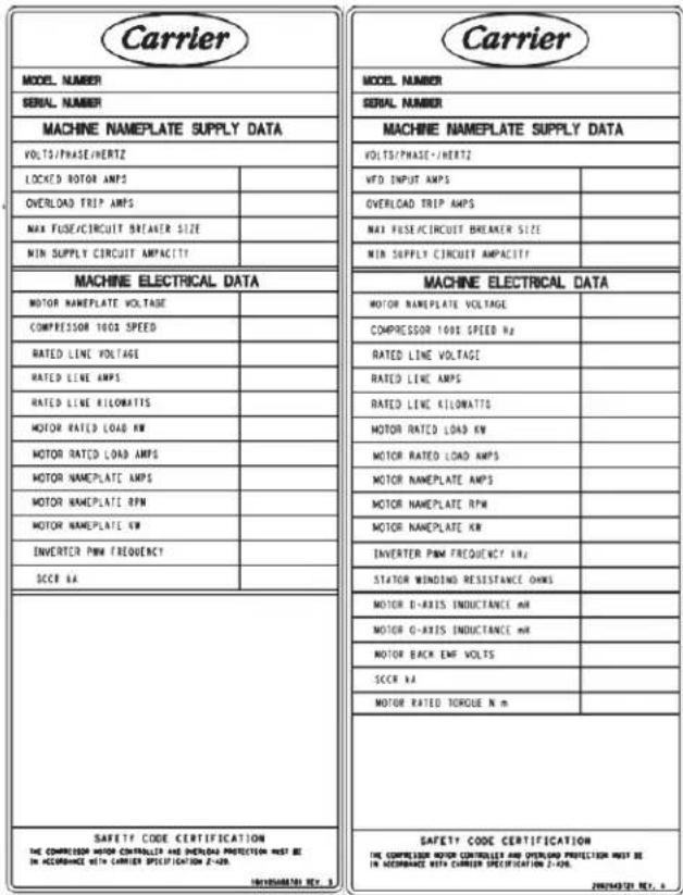
Fig. 34 — 19XRV/19MV Machine Nameplate
Configure the VFD
All configurations required by the VFD are supplied by the HMI through the VFD Gateway. The Danfoss Std Tier VFD can operate with PIC6 via LEN. Any configuration changes necessary and possible are made on the HMI screens. A complete set of configurations is transmitted to the VFD each time the controls are powered up.
Table 7 shows parameters in the Unit Mounted VFD Configuration menu for PIC6. Parameters in italics are to be entered or confirmed at start-up.
Table 7 — VFD Configuration (PIC6/UM VFD Configuration) CFGUMVFD - UM VFD Configuration
| PARAMETER ^a | DEFAULT VALUE |
| COMPRESSOR 100% SPEED | 60 |
| RATED LINE VOLTAGE | 460 |
| MOTOR NAMEPLATE CURRENT | 200 |
| MOTOR RATED LOAD CURRENT | 200 |
| MOTOR NAMEPLATE VOLTAGE ^b | 460 |
| MOTOR NAMEPLATE RPM | 3000 |
| MOTOR NAMEPLATE KW | 1500 |
| INCREASE RAMP TIME ^b | 30 |
| DECREASE RAMP TIME ^b | 30 |
| MOTOR RATED TORQUE (NM) ^c | 1500 |
| SWITCH FREQUENCY (kHz) ^c | 5 |
| STATOR RESISTANCE (Rs) ^c | 0.001 |
| D-AXIS INDUCTANCE (Ld) ^c | 0.010 |
| Q-AXIS INDUCTANCE (Lq) ^c | 0.010 |
| BACK EMF AT 1000 RPM ^c | 10 |
NOTE(S):
a. Parameters in italics are to be entered or confirmed at start-up.
b. 19XRV only
c. 19MV only
Commissioning the Unit
The commission procedure is as follows:
- If the chiller has been stored outdoors, allow at least 24 hours room temperature stabilization prior to commissioning. Ensure any condensation that occurs as a result of the ambient temperature is allowed to evaporate.
- Verify parameters in the VFD_CONF UM VFD Config (CFGUMVFD) screen against chiller nameplate.
- Install surge suppression devices if required.
- Review the power wiring and grounding to ensure that it has been properly connected.
- Visually examine the inside of the drive enclosure to:
a. Look for signs of corrosion or moisture residue.
b. Remove any dirt or debris.
c. Make sure all vents are clear.
- Apply power to the drive and take thermal measurements of the capacitor bank and power connections. Do this again before start-up.
©
©
©
Table 8 — Typical Fault Code Descriptions and Corrective Actions* (cont)
| DANFOSS ALARM/WARNING CODE | DANFOSS ALARM | PIC6 ALARM CODE | PIC6 - DESCRIPTION | PIC6 DISPLAY DANFOSS VFD ALARM IN MAINTENANCE MENU | DESCRIPTION AND POSSIBLE CORRECTIVE ACTION |
| 33 Inrush | fault 449 VFD Fault | Inrush Fault | Excessive power-ups have occurred within a short time period. Allow unit to cool. Check DC bus voltage. | ||
| 34 | Fieldbus communication fault | 449 VFD Fault | Field Bus Fault | The fieldbus on the communication option card is not working. Verify that the wiring is correct. In addition, verify parameter 8.01 = 0 Digital and ctrl.word and 8.02 = 1 FC Port. | |
| 36 Mains | failure 454 | VFD Fault - Main Power Failure | Mains failure Check fuses to drive and supply power to the chiller. | ||
| 38 Internal | fault 449 VFD Fault | Internal Fault | When an internal fault occurs, a code number is shown. This fault occurs when there is a communication error between the control card and the power card. Try the following: Cycle power, check that any options are installed correctly, check for loose or missing wires. It may be necessary to contact Danfoss Technical Support. | ||
| 39 Heat sink sensor | 449 VFD Fault | Fault — | No feedback from the heat sink temperature sensor. The power card does not sense the IGBT thermal sensor. Problem could be the power card, the gatedrive card or the ribbon cable connection between the power card and gatedrive card. | ||
| 40 | Warning - overload of digital output terminal 27. | 449 VFD Fault — | Check the load connection to terminal 27 and remove the short-circuit connection. | ||
| 45 | Earth Fault While Ramping | 449 | VFD Fault | — | There is current from the output phase to ground, either in the cable between the drive and the motor, or in the motor itself. The current transducers detect the ground fault by measuring current going out from the drive and current going into the drive from the motor. Ground fault is issued if the deviation of the two currents is too large. The current going out of the drive must be the same as the current going into the drive. Troubleshoot as follows: Remove AC power from the drive and disconnect the motor. Power the drive back on and reset the fault by pressing the "Reset" key. Run the VFD with no motor to see if the fault appears or if the drive runs without tripping. Observe the motor current in the display. It should be very close to zero with no motor connected. Reconnect the motor and attempt to run the drive again. If the drive trips on an "Alarm 14" with the motor disconnected, then the problem is inside the drive. A bad current sensor is most likely the cause of this type of fault. If the drive runs without the motor connected, but the current shown in the display is greater than 0.3 amps then it has a faulty current sensor. If the drive runs with no motor connected and the current shown in the display is less than 0.3 amps, then the ground fault is likely in the connecting cables or the motor. Check the motor and connected cables with a megohmmeter to find out which has the short. May need to check motor internal lugs with a megohmmeter to find out if short is in the motor terminal. reconnect the motor. In the event that there is current shown in the display with no motor connected, performing a "manual initialization" of the drive might help in zeroing out the current sensors. With power off, press and hold the "Status", "Main Menu" and "OK" keys on the keypad (not provided). Power the drive back on while holding the keys for 5 seconds. The drive will power up in an alarm 80 "Drive Initialization" if successful. WARNING: A manual initialization will cause the drive to revert back to factory default settings, wiping out all parameter changes, any fault log data, and any personal menu settings that have been made, so ensure the drive parameter file with MCT 10 has been downloaded prior to doing this reset. |
| 46 | Power card supply | 449 | VFD Fault | — | The supply on the power card is out of range. Check for a defective power card, control card, option card, 24 V DC power supply, defective heat sink fan. |
| 47 | 24 V supply low | 449 | VFD Fault | 24V Supply Fault | The supply on the power card is out of range. Check for a defective power card. |
| 48 | 1.8 V supply low | 449 | VFD Fault | 1.8V Supply Fault | The 1.8 V DC supply used on the control card is outside of the allowable limits. The supply is measured on the control card. Check for a defective control card. If an option card is present, check for overvoltage. |
| 57 | AMA internal fault | 449 | VFD Fault | AMA Not OK | Not relevant; Carrier default has AMA =0 [off]. |
| 59 | Current Limit | 449 | VFD Fault | — | Current is higher than the value in P4-18 Current Limit. Verify configured motor data. |
| 65 | Control card over temperature | 449 VFD Fault | Ctrl Card overtemp | The cutout temperature of the control card is 85^ C( 185^ F) . Check the following: Ambient temperature, clogged filters, fan operation, control card. | |
| 67 | Option module configuration has changed | 449 VFD Fault | Option Change | One or more options have either been added or removed since the last power-down. Check that the configuration change is intentional and reset the unit. | |
Table 8 — Typical Fault Code Descriptions and Corrective Actions* (cont)
| DANFOSS ALARM/WARNING CODE | DANFOSS ALARM | PIC6 ALARM CODE | PIC6 - DESCRIPTION | PIC6 DISPLAY DANFOSS VFD ALARM IN MAINTENANCE MENU | DESCRIPTION AND POSSIBLE CORRECTIVE ACTION |
| 68 Safe Stop activated 449 VFD Fault Safe Stop | Safe Torque Off (STO) has been activated. To resume normal operation, apply 24 V DC to terminal 37, then send a reset signal (via bus, digital I/O, or by pressing [Reset]). | ||||
| 69 | Power card temperature | 449 VFD Fault | — | The power card temperature sensor is either too cold or too hot. Verify ambient operating temperature, check filters, verify fans are operating, check power card. | |
| 70 | Illegal FC configuration | 449 VFD Fault | — | Control and power cards are incompatible. Verify type code from unit nameplate and part numbers of cards with supplier of the parts. | |
| 71 PTC 1 | Safe Stop 449 VFD Fault PTC1 Safe Stop | Safe Torque Off (STO) has been activated from the VLT PTC Thermistor Card MCB 112 because the motor is too warm. Once the motor cools and the digital input from the MCB 112 is deactivated, normal operation can resume when the MCB 112 applies 24 V DC to terminal 37 again. When the motor is ready for normal operation, a reset signal is sent (via serial communication, digital I/O, or by pressing [Reset] on the LCP). If automatic restart is enabled, the motor can start when the fault is cleared. | |||
| 72 Dangerous failure 449 VFD Fault Dangerous Failure | Safe Torque Off (STO) with trip lock. Unexpected signal levels on safe torque off and digital input from the VLT PTC Thermistor Card MCB 112. | ||||
| 79 | Illegal power section configuration | 449 VFD Fault | — | The power card scaling card is incorrect or is not installed. | |
| 80 | Drive initialized to default value | 449 VFD Fault | Drive Initialized | Parameter settings are initialized to default settings after a manual reset. To clear alarm, reset unit. | |
| 94 | End of curve | 449 | VFD Fault | End of Curve | 22-50=[0]Off |
| 95 | Broken belt | 449 | VFD Fault | Broken Belt | 22-60=[0]Off |
| 99 | Locked rotor | 449 | VFD Fault | — | An overload condition was detected. This can indicate a locked compressor/motor. Further inspection is required. |
| 243 | Brake IGBT | 449 | VFD Fault | Brake IGBT Fault | Not relevant; no brake IGBT. |
| 245 | Heat Sink Sensor | 449 | VFD Fault | — | No feedback from the heat sink sensor. See Alarm 39. |
| 250 | New spare part | 449 | VFD Fault | N/A | Parameter 14-23 type code (T/C) must be set correctly. Will occur when power or switch mode supply has been replaced and the drive type code must be set correctly in EEPROM in accordance with the drive label. At index number 20 in parameter 14-23 enter Save to EEPROM and press the OK key. Alarm will change to Alarm 251. To reset alarm 251 remove power to the unit and reapply power and press the Reset key to clear the alarm. Important: A keypad is required to enter the type code. |
| 251 | New type code | 449 | VFD Fault | Service Trip, Type code | The power card or other components have been replaced and the type code has been changed. Cycle power and reset the drive to remove the warning and to resume normal operation. |
| N/A | N/A | 311 | N/A | Loss Communication with Danfoss VFD | LEN Communication error with VFD is lost. Check wiring. Note that for new drive not factory configured for Carrier or after software upgrade LEN must be enabled. Set parameter 14-29 to 00006100. This gives access to hidden parameter 14-23. Change this parameter using a field-provided keypad With keypad: Press OK once. You should now have a cursor on the value [00] just below the parameter number and name. Increase this by pressing the UP key until the value [12] and you see this on the line below: "[nnn] SXXX (std. sw)". Press OK and change to "[nnn] S009 (Special sw)", with the UP and DOWN buttons. Press OK again. You should have the cursor in the same place as on the previous step. Press UP until the value is [20]; press OK; change to [1] Save to EEPROM; press OK. You should now get a trip lock alarm A251 New Type Code. Do a power cycle and reset the alarm. It should be okay now. Check parameter 8-30; change it to [20] LEN if necessary. |
NOTE: This is not a complete list of Danfoss FC102 codes. If a warning/alarm is present which is not included in this table refer to the Danfoss manual.
Checking Power Modules and Motor Input with Input Power Off — Static Test
Use the following procedure to check the drive's power module circuitry with power off:
- Turn off and lock out input power. Wait appropriate time as per Danfoss VFD nameplate.
- Verify there is no voltage at the drive's input power terminals.
- Using a voltmeter, check the DC bus potential as described in the section Verifying That DC Bus Capacitors Are Discharged to ensure the DC bus capacitors are discharged.
- Disconnect the motor from the drive.
- Check all AC line and DC bus fuses.
- Use a multimeter to perform a static check on the input diodes and output IGBTs. See Table 9. For parallel drives this test will have to be done for each individual drive module, so in addition to removing the input and motor busbars for parallel drives the DC link connection will have to be removed for the individual drives.
- Check motor impedance.
- Reconnect the motor to the drive.
- Reapply input power.
WARNING
DC bus capacitors retain hazardous voltages after input power has been disconnected. After disconnecting input power, wait the time specified in Table 1 or as specified on the Danfoss VFD nameplate. For the DC bus capacitors to discharge and then check the voltage with a voltmeter rated for the DC bus voltage to ensure the DC bus capacitors are discharged before touching any internal components. For parallel drive modules (N630 and larger) check voltage before and after the individual DC fuses. Failure to observe this precaution could result in severe bodily injury or loss of life.
An isolated multimeter will be needed to measure DC bus voltage and to make resistance checks.
Table 9 — Diode Checks
| METER LEAD | METER READING | |
| (+) (-) | ||
| R | DC+ Infinite (OV) | |
| DC- | Infinite (OV) | |
| S | DC+ | Infinite (OV) |
| DC- Infinite (OL) | ||
| T | DC+ | Infinite (OV) |
| DC- | Infinite (OV) | |
| U | DC+ | 0.3 to 0.7 v |
| DC- Infinite (OL) | ||
| V | DC+ | 0.3 to 0.7 v |
| DC- Infinite (OL) | ||
| W | DC+ | 0.3 to 0.7 v |
| DC- Infinite (OL) | ||
| DC+ | R | Infinite (OL) |
| S | ||
| T | ||
| U | ||
| V | ||
| W | ||
| DC- | R | 0.3-0.7v |
| S | ||
| T | ||
| U | ||
| V | ||
| W | ||
Digital meters require a special diode check function because the current sourced by the meter during a normal resistance (Ohms) test is too low to accurately test a diode. Make sure the meter is set to the diode test function. Voltage readings may not be exact as shown in above table, but look for consistency during each of the 4 tests. When performing a test that should return infinity (OL) as shown in above table, you should see a value slowly climbing toward infinity. This is a result of the meter charging a capacitor and is normal.
If an incorrect reading is observed associated with U, V, W (outputs) this indicates a failed inverter IGBT module. Replace the shorted IGBT modules. Similarly if an incorrect reading is observed associated with R, S, T (inputs) this indicates a shorted SCR. Replace the shorted SCR module.
Servicing the Drive
WARNING
To guard against possible personal injury and/or equipment damage:
- Inspect all lifting hardware for proper attachment before lifting drive.
- Do not allow any part of the drive or lifting mechanism to make contact with electrically charged conductors or components.
- Do not subject the drive to high rates of acceleration or deceleration while transporting to the mounting location or when lifting.
Do not allow personnel or their limbs directly underneath the drive when it is being lifted and mounted.
WARNING
DC bus capacitors retain hazardous voltages after input power has been disconnected. After disconnecting input power, wait the time specified in Table 1 or as specified on the Danfoss VFD nameplate. For the DC bus capacitors to discharge and then check the voltage with a voltmeter rated for the DC bus voltage to ensure the DC bus capacitors are discharged before touching any internal components. For parallel drive modules (N630 and larger) check voltage before and after the individual DC fuses. Failure to observe this precaution could result in severe bodily injury or loss of life.
An isolated multimeter will be needed to measure DC bus voltage and to make resistance checks.
Refer to Fig. 35 for location of DC bus terminals.
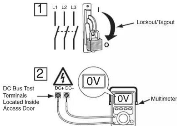
Fig. 35 — Check DC Bus Terminals
For FC102 service guide lines, refer to Danfoss Manuals; the latest Service Guide for VLT FC Series is MG94A502.
APPENDIX A — WIRING SCHEMATICS
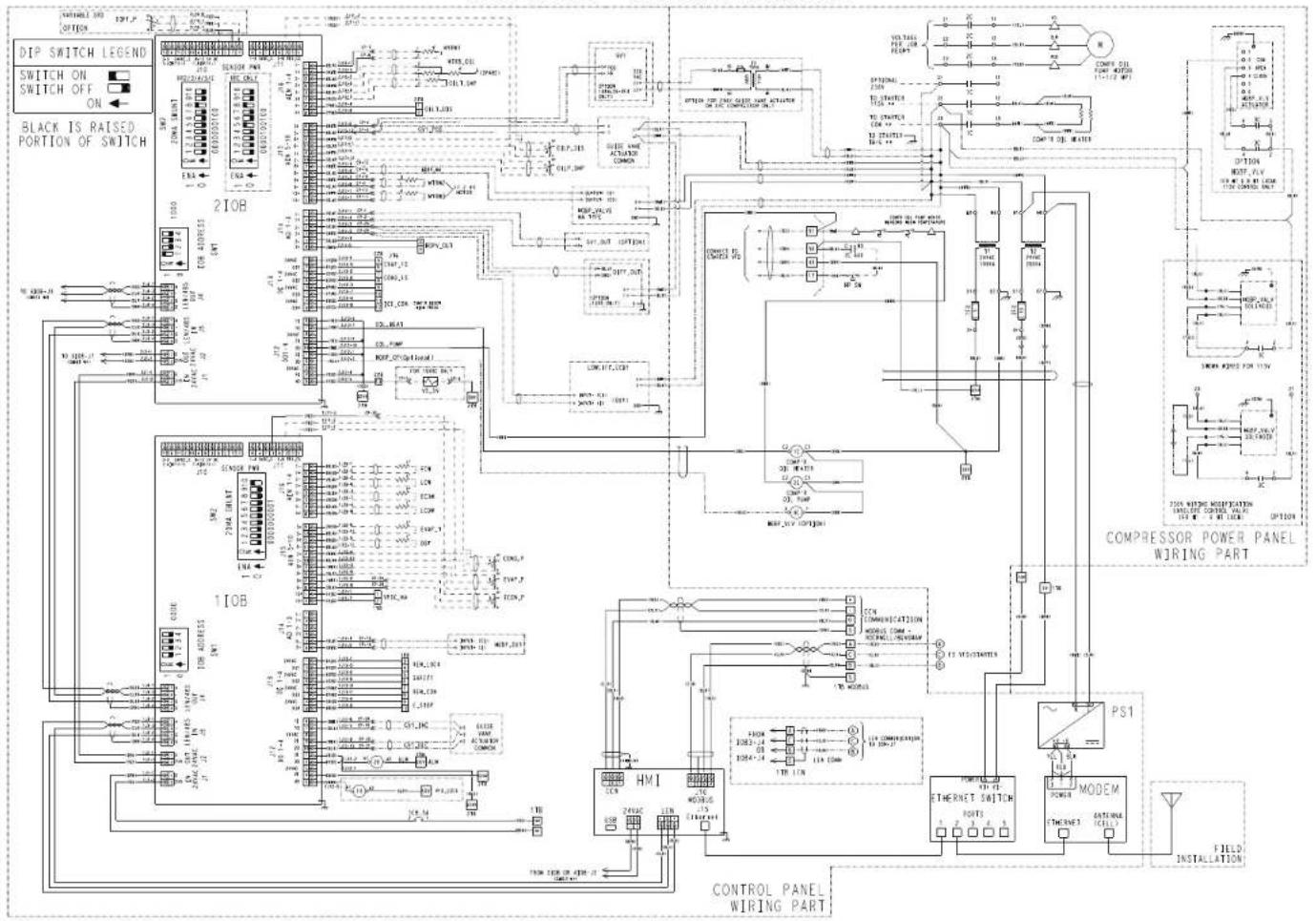
19XR05044702 REV L
Fig. A - 19XRV Chiller Control Schematic (PIC6)
APPENDIX A — WIRING SCHEMATICS (CONT)
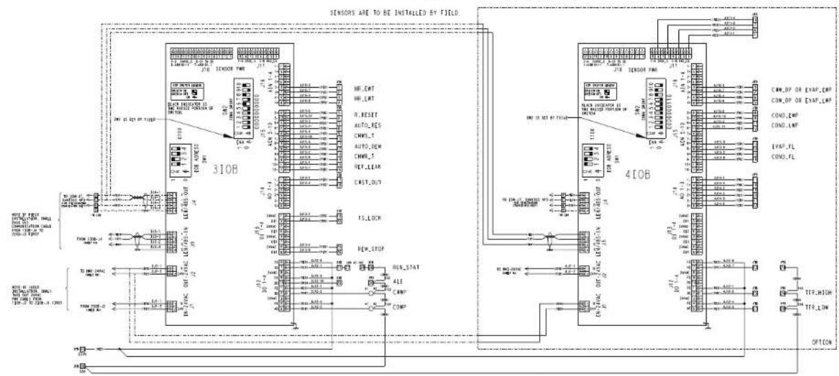
flowchart
graph TD
    subgraph Sensor1
        A["310B Module"] --> B["Max"]
        A --> C["OR"]
        A --> D["Input"]
        A --> E["Output"]
    end

    subgraph Sensor2
        F["410B Module"] --> G["Max"]
        F --> H["OR"]
        F --> I["Input"]
        F --> J["Output"]
    end

    subgraph Control
        K["MINI OF EXAP_LWP"] --> L["MINI OF EXAP_LWP"]
        M["MINI OF EXAP_LWP"] --> N["MINI OF EXAP_LWP"]
        O["MINI OF EXAP_LWP"] --> P["MINI OF EXAP_LWP"]
        Q["MINI OF EXAP_LWP"] --> R["MINI OF EXAP_LWP"]
        S["MINI OF EXAP_LWP"] --> T["MINI OF EXAP_LWP"]
        U["MINI OF EXAP_LWP"] --> V["MINI OF EXAP_LWP"]
        W["MINI OF EXAP_LWP"] --> X["MINI OF EXAP_LWP"]
        Y["MINI OF EXAP_LWP"] --> Z["MINI OF EXAP_LWP"]
        AA["MINI OF EXAP_LWP"] --> AB["MINI OF EXAP_LWP"]
        AC["MINI OF EXAP_LWP"] --> AD["MINI OF EXAP_LWP"]
        AE["MINI OF EXAP_LWP"] --> AF["MINI OF EXAP_LWP"]
        AG["MINI OF EXAP_LWP"] --> AH["MINI OF EXAP_LWP"]
        AI["MINI OF EXAP_LWP"] --> AJ["MINI OF EXAP_LWP"]
        AK["MINI OF EXAP_LWP"] --> AL["MINI OF EXAP_LWP"]
        AM["MINI OF EXAP_LWP"] --> AN["MINI OF EXAP_LWP"]
        AO["MINI OF EXAP_LWP"] --> AP["MINI OF EXAP_LWP"]
        AQ["MINI OF EXAP_LWP"] --> AR["MINI OF EXAP_LWP"]
        AS["MINI OF EXAP_LWP"] --> AT["MINI OF EXAP_LWP"]
        AU["MINI OF EXAP_LWP"] --> AV["MINI OF EXAP_LWP"]
        AW["MINI OF EXAP_LWP"] --> AX["MINI OF EXAP_LWP"]
        AY["MINI OF EXAP_LWP"] --> AZ["MINI OF EXAP_LWP"]
        BA["MINI OF EXAP_LWP"] --> BB["MINI OF EXAP_LWP"]
        BC["MINI OF EXAP_LWP"] --> BD["MINI OF EXAP_LWP"]
        BE["MINI OF EXAP_LWP"] --> BF["MINI OF EXAP_LWP"]
        BG["MINI OF EXAP_LWP"] --> BH["MINI OF EXAP_LWP"]
        BI["MINI OF EXAP_LWP"] --> BJ["MINI OF EXAP_LWP"]
        BK["MINI OF EXAP_LWP"] --> BL["MINI OF EXAP_LWP"]
        BM["MINI OF EXAP_LWP"] --> BN["MINI OF EXAP_LWP"]
        BO["MINI OF EXAP_LWP"] --> BP["MINI OF EXAP_LWP"]
        BQ["MINI OF EXAP_LWP"] --> BR["MINI OF EXAP_LWP"]
        BS["MINI OF EXAP_LWP"] --> BT["MINI OF EXAP_LWP"]
        BU["MINI OF EXAP_LWP"] --> BV["MINI OF EXAP_LWP"]
        BW["MINI OF EXAP_LWP"] --> BX["MINI OF EXAP_LWP"]
        BYD["MINI OF EXAP_LWP"] --> BZ["MINI OF EXAP_LWP"]
        CA["MINI OF EXAP_LWP"] --> CB["MINI OF EXAP_LWP"]
        CC["MINI OF EXAP_LWP"] --> CD["MINI OF EXAP_LWP"]
        CE["TTR_HIGH"] --> CF["TTR_LOW"]
    end

    subgraph Control
    G
    H
    I
    J
    K
    L
    M
    N
    O
    P
    Q
    R
    S
    T
    U
    V
    W
    X
    Y
    Z
    AA
    AB
    AC
    AD
    AE
    AF
    AG
    AH
    AI
    AJ
    AK
    AL
    AM
    AN
    AO
    AP
    AQ
    AR
    AS
    AT
    AU
    AV
    AW
    AX
    AY
    AZ
    BA
    BB
    BC
    BD
    BE
    BF
    BG
    BH
    BI
    AJ
    AK
    AL
    AM
    AN
    AO
    AP
    AQ
    AW
    AX
    AY
    AZ
    BA
    BB
    BC
    BD
    BE
    BF
    BG
    BH
    BI
    AJ
    AK
    AL
    AM
    AN
    AO
    AP
    AQ
    AW
    AX
    AY
    AZ
    BA
    BB
    BC
   BD
    BE
    BF
    BG
    BH
    BI
    AJ
    AK
    AL
    AM
    AN
    AO
    AP
    AQ
    AW
    AX
    AY
    AZ
    BA
    BB
    BC
   BD
    BE
    BF
    BG
    BH
    BI
    AJ
    AK
    AL
    AM
    AN
    AO
    Ap
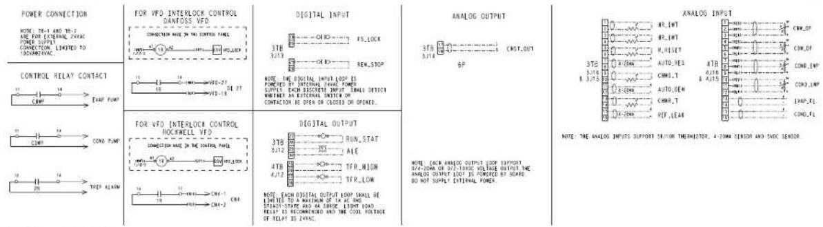
19XR05044703 REV L
Fig. A - 19XRV Chiller Control Schematic (PIC6) (cont)
APPENDIX A — WIRING SCHEMATICS (CONT)
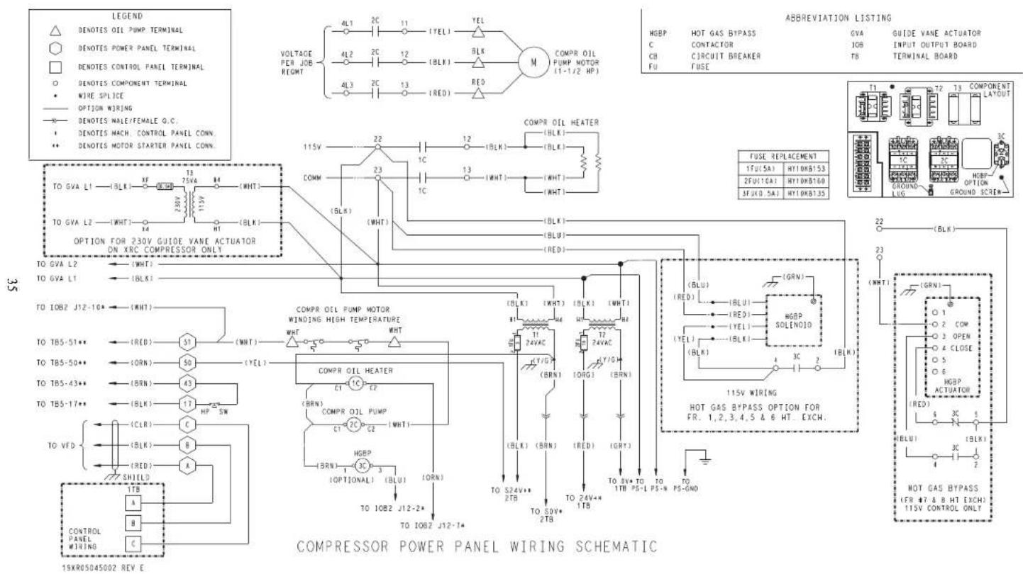
Fig. B — 19XRV Compressor Power Panel Schematic
36
APPENDIX A — WIRING SCHEMATICS (CONT)
![TO 3108-JA LEN/485-IN (ICE (MOYA) K) 2 J2-3 RED 16 2 J2-3 VIO 16 2 J2-3 WNT 16 2 J2-3 GND C2 20 L12 LEN/485-IN J12 POWER IN 3 J15-1 RED 16 CB1 CB1,1 RED 16 47.8 5 J15-2 GNT 16 ECP ESTOP,3 STATUS CONF.FS L12 EVAF.FS OPTIONAL ICE,CON SWI,STOP REN,CON OPTIONAL SEM,LOCH ECON,P SV EVAF,P SV CONO,P SV EVAF,T LCW ECW ECN OPTIONAL AUTO,THW 7 J2-3 VIO 16 7 J2-3 VIO 16 7 J2-3 VIO 16 7 J2-3 VIO 16 7 J2-3 VIO 16 7 J2-3 VIO 16 7 J2-3 VIO 16 7 J2-3 VIO 16 7 J2-3 VIO 16 7 J2-3 VIO 16 EOP SWITCH LEO/NO Switch ON Switch OFF SN1 ADDRESS:0000 4321 TIRLE 5 J2-3 GNT 16 5 J2-3 BLU 16 5 J2-3 VIO 16 5 J2-3 VIO 16 5 J2-3 VIO 16 ICR,A1 VIO 16 ICR,A2 GNT 16 ACR,A1 VIO 16 ACR,A2 GNT 16 NOT USED EXP.COL.SYS.VLT ATR INT,RON,STAT ECONJER ECV ECON,EV,2 GNT 20 ECON,EV,3 HDT 20 ECON,EV,4 SEL 20 ECON,EV,4 RIN 20 CONDENSER ECV CONDENSER ECV TO MTI [SEE SHEET MTI] J1.5 LEN/485-OUT J2.4 POWER OUT J1.9 LEN/485-OUT J2.4 POWER OUT](/content/2026/05/895893/images/ed6bb11bad82d39a1eb6fceb117eda7090ee82ca5a4fe6b3416af7ee5ac4dc7a.jpg)
2001503201 REV. 0
| SYMBOL LEGEND | |
| ☐ | TERMINAL BLOCK |
| ☐ | FEMALE CONNECTOR |
| ☐ | MALE CONNECTOR |
| ...... | OPTIONAL WIRING |
| ⊥ | NORMALLY OPEN |
| ⊥ | NORMALLY CLOSED |
| ⊥ | CONTACT (N O.) |
| ⊥ | CONTACT (N C.) |
| THERMOSTAT | |
| ∅ | THERMISTOR |
| ∅ | COIL |
| ∅ | CARLE |
| T | PRESSURE SWITCH |
| T | PRESSURE TRANSDUCER |
| ∅ | FUSE |
| ∅ | CIRCUIT BREAKER |
| ∅ | FLOW SWITCH |
| ↓ | GROUND |
Fig. C — 19MV SIOB
APPENDIX A — WIRING SCHEMATICS (CONT)
Fig. D — 19MV IOB2
APPENDIX A — WIRING SCHEMATICS (CONT)
Fig. E — 19MV IOB3
APPENDIX A — WIRING SCHEMATICS (CONT)
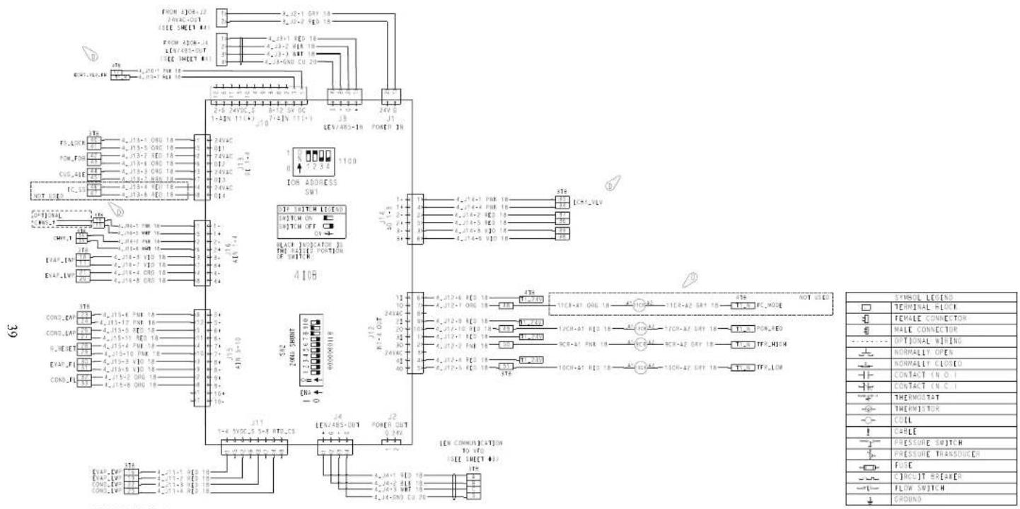
Fig. F — 19MV IOB4
APPENDIX A — WIRING SCHEMATICS (CONT)
| SYMBOL LEGEND | |
| TERMINAL BLOCK | |
| FEMALE CONNECTOR | |
| MALE CONNECTOR | |
| OPTIONAL WIRING | |
| NORMALLY OPEN | |
| NORMALLY CLOSED | |
| CONTACT (V.O.) | |
| CONTACT (V.C.) | |
| THERMOSTAT | |
| THERWISTOR | |
| COIL | |
| CABLE | |
| PRESSURE SWITCH | |
| PRESSURE TRANSDUCER | |
| FUSE | |
| CIRCUIT BREAKER | |
| FLOW SWITCH | |
| GROUND | |
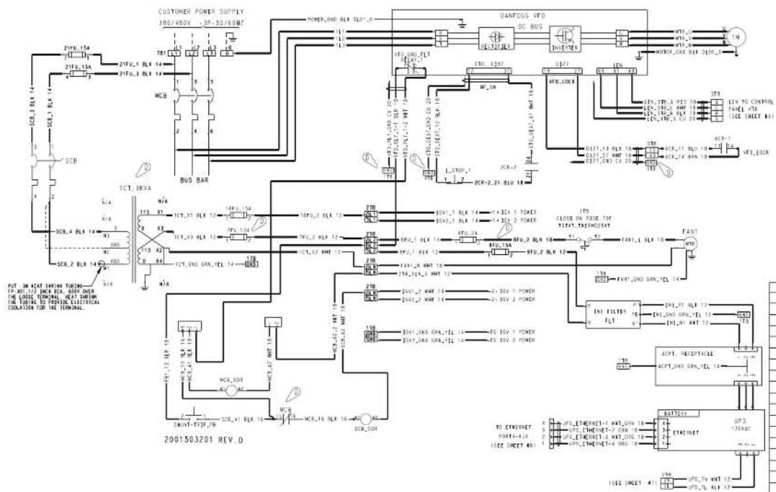
Fig. G — 19MV Customer Power Supply and Danfoss VFD Wiring
41
flowchart
graph TD
    A["Motor Bearing Control Board (MBC)"] --> B["AT 21G"]
    B --> C["CONOC DEMOS"]
    C --> D["30V 24VDC SET"]
    D --> E["Switched 24VDC"]
    E --> F["75V 218.3"]
    F --> G["RESUM/REF"]
    G --> H["RESUM/REF"]
    H --> I["RESUM/REF"]
    I --> J["RESUM/REF"]
    J --> K["TX 200VA"]
    K --> L["TX 200VA"]
    L --> M["TX 200VA"]
    M --> N["TX 200VA"]
    N --> O["TX 200VA"]
    O --> P["TX 200VA"]
    P --> Q["TX 200VA"]
    Q --> R["TX 200VA"]
    R --> S["TX 200VA"]
    S --> T["TX 200VA"]
    T --> U["TX 200VA"]
    U --> V["TX 200VA"]
    V --> W["TX 200VA"]
    W --> X["TX 200VA"]
    X --> Y["TX 200VA"]
    Y --> Z["TX 200VA"]
    Z --> AA["TX 200VA"]
    AA --> AB["TX 200VA"]
    AB --> AC["TX 200VA"]
    AC --> AD["TX 200VA"]
    AD --> AE["TX 200VA"]
    AE --> AF["TX 200VA"]
    AF --> AG["TX 200VA"]
    AG --> AH["TX 200VA"]
    AH --> AI["TX 200VA"]
    AI --> AJ["TX 200VA"]
    AJ --> AK["TX 200VA"]
    AK --> AL["TX 200VA"]
    AL --> AM["TX 200VA"]
    AM --> AN["TX 200VA"]
    AN --> AO["TX 200VA"]
    AO --> AP["TX 200VA"]
    AP --> AQ["TX 200VA"]
    AQ --> AR["TX 200VA"]
    AR --> AS["TX 200VA"]
    AS --> AT["TX 200VA"]
    AT --> AU["TX 200VA"]
    AU --> AV["TX 200VA"]
    AV --> AW["TX 200VA"]
    AW --> AX["TX 200VA"]
    AX --> AY["TX 200VA"]
    AY --> AZ["TX 200VA"]
    AZ --> BA["TX 200VA"]
    BA --> BB["TX 200VA"]
    BB --> BC["TX 200VA"]
    BC --> BD["TX 200VA"]
    BD --> BE["TX 200VA"]
    BE --> BF["TX 200VA"]
    BF --> BG["TX 200VA"]
    BG --> BH["TX 200VA"]
    BH --> BI["TX 200VA"]
    BI --> BJ["TX 200VA"]
    BJ --> BK["TX 200VA"]
    BK --> BL["TX 200VA"]
    BL --> BM["TX 200VA"]
    BM --> BN["TX 200VA"]
    BN --> BO["TX 200VA"]
    BO --> BP["TX 200VA"]
    BP --> BQ["TX 200VA"]
    BQ --> BR["TX 200VA"]
    BR --> BS["TX 200VA"]
    BS --> BT["TX 200VA"]
    BT --> BU["TX 200VA"]
    BU --> BV["TX 200VA"]
    BV --> BW["TX 200VA"]
    BW --> BX["TX 200VA"]
    BX --> BY["TX 200VA"]
    BY --> BZ["TX 200VA"]
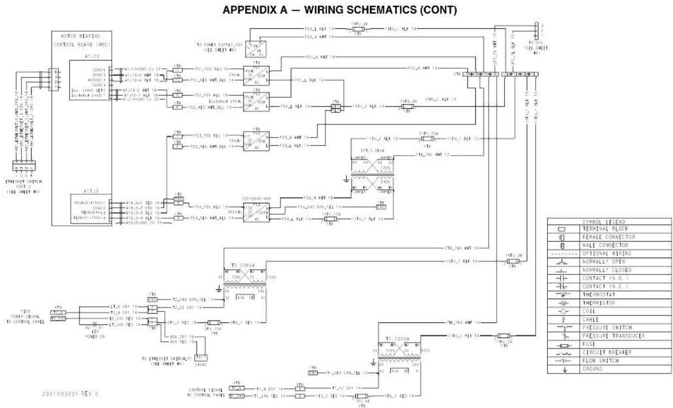
Fig. H — 19MV Motor Bearing Control Board Wiring
APPENDIX A — WIRING SCHEMATICS (CONT)
2001503201 REV D
| SYMBOL LEGEND | |
| TERMINAL BLOCK | |
| FEMALE CONNECTOR | |
| MALE CONNECTOR | |
| OPTIONAL WIRING | |
| NORMALLY OPEN | |
| NORMALLY CLOSED | |
| CONTACT (N.O.) | |
| CONTACT (N.C.) | |
| THERMOSTAT | |
| THERMISTOR | |
| COIL | |
| CABLE | |
| PRESSURE SWITCH | |
| PRESSURE TRANSDUCER | |
| FUSE | |
| CIRCUIT BREAKER | |
| FLOW SWITCH | |
| GROUND | |
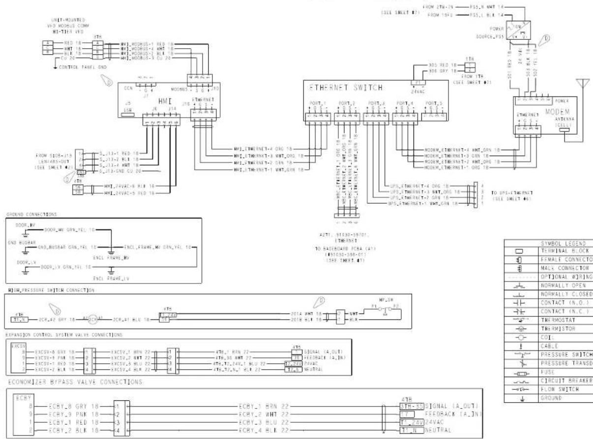
Fig. I — 19MV HMI and Ethernet Switch Wiring
43
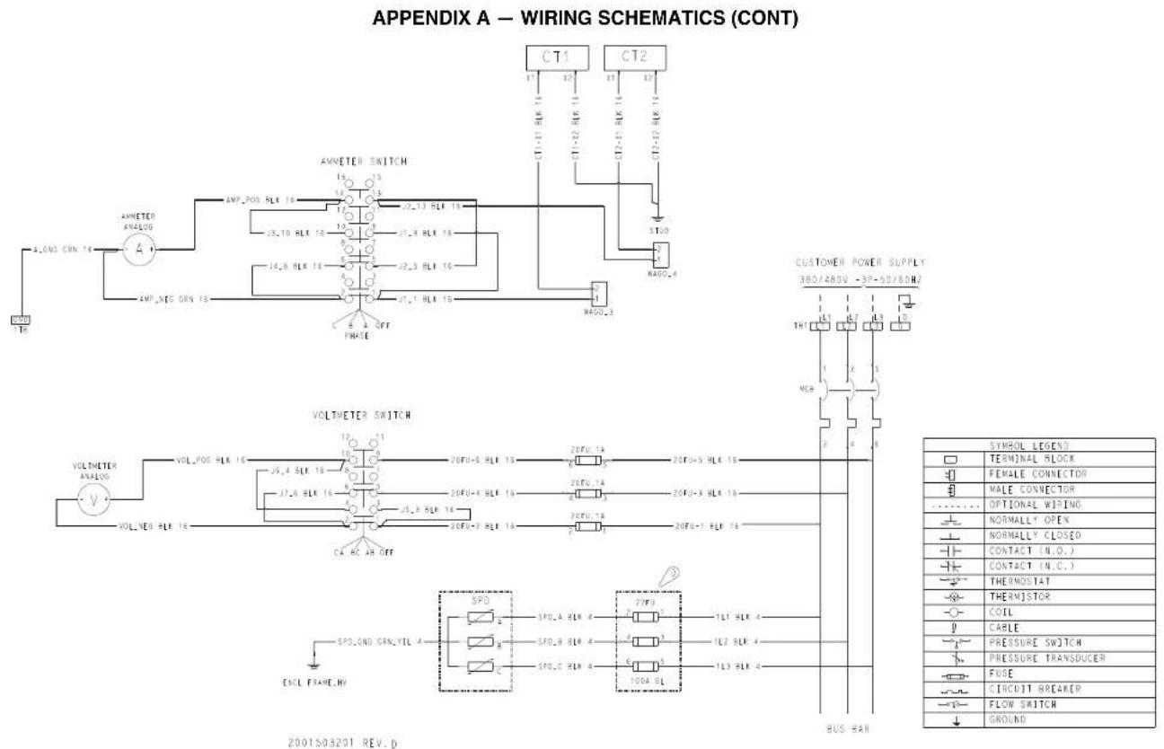
Fig. J — 19MV Ammeter Switch and Voltmeter Switch Wiring
APPENDIX A — WIRING SCHEMATICS (CONT)
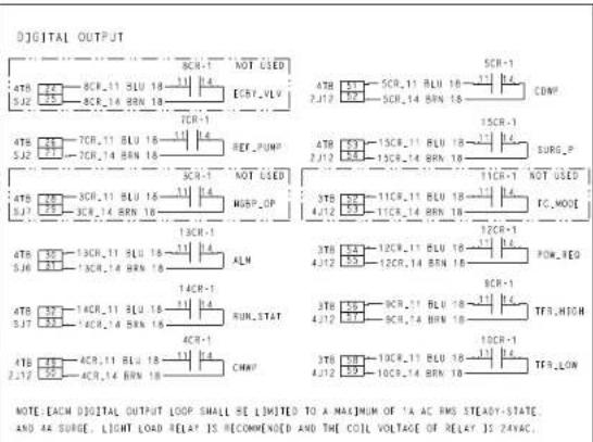 | DIGITAL INPUT4TB2J13 47 SPARE,SAFETYFS.LOCI3TB4J13 POW.FDBCUS.ALENOT USEDFC.05NOTE THE DIGITAL INPUT LOOP ISPOWERED BY INTERNAL ZAVAC POWERSUPPLY. EACH DISCRETE INPUT SMALL DETECTWHETHER AN EXTERNAL SWITCH ORCONTRACTOR IS OPEN OR CLOSE B OR OPENED. | ANALOG INPUT4TB2J16 47 CHWR.T4TB2J15 47 REF.LEAK4TB2J15 47 AUTO.RES4TB5J9 47 CHWS.T4TB5J11 47 AUTO.DEW4TB5J16 47 EVAP.CAP4TB5J15 47 R,RESET4TB5J16 47 EVAP.FL4TB5J11 47 COND.FLMOTE THE ANALOG INPUTS SUPPORT SW/10R THERMISTOR, 4-20MA SENSOR AND SVDC SENSOR. | |
| ANALOG OUTPUTNOTE EACH ANALOG OUTPUT LOOP SUPPORT 0/4-20MA OR0/7-10VDC VOLTAGE OUTPUT THE ANALOG OUTPUT LOOP ISPOWERED BY BOARD DO NOT SUPPLY EXTERNAL POWER. | POWER CONNECTIONNOTE: TH-1 AND TH-2 ARE FOR EXTERNALZAVAC POWER SUPPLY CONNECTION.LIMITED TO 10VAP ZAVAC. | ||
| WATER PUMP CONTROL RELAY CONTACTCHWP11 PACDWPP11 PA | |||
Fig. K — 19MV Field Wiring

- WARNING
- CAUTION
- INTRODUCTION
- ABBREVIATIONS AND EXPLANATIONS
- Required Publications
- Getting Assistance from Danfoss
- Carrier P/N:
- DANGER
- IDENTIFYING DRIVE COMPONENTS
- Rigging
- D, E SIZES
- PARALLEL DRIVE MODULES
- Components and Physical Data
- D Size Drive
- E Size Drive
- D and E Size VFD Power Panel Schematics — 19XRV
- PD Size Drive
- PARALLEL DRIVE SYSTEMS - DP1120 - DP1670
- Control Shelf
- PD Module
- DC Bus
- START-UP Alternate Wire Lugs
- Verify Installation
- Configure the VFD
- Commissioning the Unit
- Checking Power Modules and Motor Input with Input Power Off — Static Test
- Servicing the Drive
- APPENDIX A — WIRING SCHEMATICS (CONT)
Brand : CARRIER
Model : AquaEdge 23XRV
Category : Compressor