
06E - Compressor CARRIER - Free user manual and instructions
Find the device manual for free 06E CARRIER in PDF.


| Product Type | Semi-hermetic reciprocating compressor |
| Brand | Carrier / Carlyle |
| Model Series | 06E |
| Displacement Range | 50 to 99 cfm at 1750 rpm |
| Number of Cylinders | 4 or 6 |
| Bore | 2-11/16 in (68.3 mm) |
| Stroke | 1-63/64 to 2-7/8 in (50.4 to 73.0 mm) depending on model |
| Oil Charge | 14 to 19 pints (6.6 to 9.0 liters) |
| Net Weight | 430 to 520 lb (195 to 236 kg) depending on model |
| Motor Power | 15 to 40 HP (11.2 to 29.8 kW) |
| Voltage Options | 208-230/460V 3-phase 60 Hz, 380V 3-phase 50 Hz, etc. |
| Overcurrent Protection | Electronic overload relay or calibrated circuit breaker |
| Refrigerants | R-404A, R-448A, R-449A, R-134a, R-407A, R-407C, R-407F, R-22, R-500, R-502, R-507 |
| Oil Type | POE (e.g., Castrol E68, ICI Emkarate RL68H) for HFC; MO or AB for CFC/HCFC |
| Oil Pressure Range | 18 to 34 psi (1.2 to 2.3 bar) above suction pressure |
| Oil Safety Switch | 120-second time delay, differential pressure 4-8 psid cut-out, 8-11 psid cut-in |
| Discharge Gas Temperature Sensor | Installed in cylinder head; protects against high temperature |
| Crankcase Heater | Required for HFC/POE systems |
| Capacity Control | Suction cut-off unloading or PWM valve with smart controller |
| Service Replacement | Valve plate packages, bearing head assembly, gaskets, oil pump parts available |
Frequently Asked Questions - 06E CARRIER
User questions about 06E CARRIER
0 question about this device. Answer the ones you know or ask your own.
Ask a new question about this device
Download the instructions for your Compressor in PDF format for free! Find your manual 06E - CARRIER and take your electronic device back in hand. On this page are published all the documents necessary for the use of your device. 06E by CARRIER.
USER MANUAL 06E CARRIER
SEMI-HERMETIC RECIPROCATING COMPRESSORS

natural_image
Abstract blue and white graphic with curved white stripes on a blue background (no text or symbols)Carlyle®
WHAT THIS GUIDE CAN DO FOR YOU
Carlyle Compressor Company provides this guide to aid the service specialist in proper installation, service, and maintenance of 06D, E, CC compressors. Following the procedures in this guide will extend the life of the system and improve performance.
This guide uses the terms DANGER, WARNING and CAUTION. These terms have specific meanings that identify the degree of hazard. Typically in the HVAC industry, these specific meanings are:

DANGER
There is an immediate hazard which WILL result in severe personal injury or death.

WARNING
Hazards or unsafe practices which COULD result in severe personal injury or death.

CAUTION
Potential hazards or unsafe practices which COULD result in minor personal injury or equipment damage
CARLYLE COMPRESSOR THANKS YOU FOR SELECTING OUR EQUIPMENT
Manufacturer reserves the right to discontinue, or change at any time, specifications or designs and prices without notice and without incurring obligations.
CARLYLE COMPRESSOR DIVISION • © 2023 CARRIER P.O. Box 4808 • Syracuse, New York 13221
HOW TO USE THIS GUIDE
This book is divided into six major sections (see Table of Contents):
SECTION 1.0 - General Compressor and Customer Information
SECTION 2.0 - Start-Up, Troubleshooting, and Service
SECTION 3.0 - Compressor Parts Data
SECTION 4.0 - Electrical Data
SECTION 5.0 - Compressor Service Worksheets
SECTION 6.0 - SMART CONTROLLER and PWM VALVE
An Index is provided in the back of this guide.
TO GET MORE HELP
Carlyle Compressor Company sells compressors to Carrier for use in their packaged units and to OEMs (Original Equipment Manufacturers) that design and build finished systems. The system manufacturer is the expert on the system, including the application of our compressor. All questions, on either the packaged system or the compressor in that system, should be first directed to the local Carrier distributor (for Carrier systems) or the OEM or its local representative (for other units). If this support, along with this service guide, cannot resolve your compressor problem, please contact our Carlyle engineering group.
CONTENTS
1.0 GENERAL COMPRESSOR AND CUSTOMER INFORMATION
1.1 Compressor Model Number Significance 6
1.2 Application Range 9
1.3 Nameplate Significance.... 10
1.4 Compressor Serial Number Significance 12
1.5 Carlyle OEM Compressor Warranty.... 13
1.6 Service Billing and Credit 13
1.7 Carlyle Service Replacement Compressors, Parts, and Support.... 14
2.0 START-UP, TROUBLESHOOTING, AND SERVICE
2.1 Technical Assistance - Carlyle OEM Compressors ...... 15
2.2 Recommended Start-Up Procedure 15
2.3 Troubleshooting Procedure 23
2.4 Service Procedures 35
2.5 Connection Points — 06D, 06E, and 06CC Compressors .. 47
2.6 Cross-Sectional View — 06D Semi-Hermetic Compressor 53
2.7 Cross-Sectional View — 06E Semi-Hermetic Compressor 53
2.8 Exploded View — 6-Cylinder 06D Compressor .... 54
2.9 Exploded View — 6-Cylinder 06E Compressor .... 56
2.10 Torque Guide — 06D and 06CC
(16 to 37 cfm) Compressors.... 58
2.11 Torque Guide — 06E and 06CC
(50 to 99 cfm) Compressors.... 59
3.0 COMPRESSOR AND PARTS DATA
3.1 06D Series Compressors — Physical Data .... 60
3.2 06E Series Compressors — Physical Data.... 62
3.3 06CC Series Compressors — Physical Data ...... 64
3.4 Refrigerants and Oils for 06D,E,CC Compressors...... 66
3.5 Oil Viscosity and Pour Points 68
3.6 Oil Additives 68
3.7 Oil Pressure 68
3.8 Replacement Oil Pump/Pump End Bearing Package...... 69
3.9 Oil Pressure Safety Switch 69
3.10 06CC, E Discharge Gas Cylinder Head Temperature Sensor and 06E Pressure Relief Valve .... 84
3.11 06D, E Cylinder Head Cooling Fans and Liquid Injection . 86
3.12 Capacity Control Accessory Packages
(Suction Cut-Off Unloading Type)...... 87
3.13 Capacity Control Coil Packages (06D, E).... 90
3.14 Crankcase Heater Data 90
3.15 Compressor Mounting Data 91
3.16 Compressor Service Valves (06D, E, CC) 92
3.17 Oil Drain Plug Adapter.... 92
3.18 Sight Glass Adapters for Oil Equalization 92
3.19 Replacement Sight Glass/Installation Tool 93
3.20 Replacement Motor End Mounting Foot.... 93
3.21 Gaskets — Cylinder Head and Valve Plate.... 94
3.22 Miscellaneous.... 95
3.23 Valve Plate Packages, Service Replacement.... 96
3.24 Muffler Recommendations.... 97
3.25 Electrical Accessories.... 98
3.26 Baffle Plate Recommendations 99
3.27 Interstage Pressure Tables (06CC Compressors Only) ..... 105
4.0 ELECTRICAL DATA
4.1 06D and 06CC (16-37 cfm) Electronic Overcurrent Protection.... 111
4.2 06D 3-Phase Electrical Specification .... 113
4.3 06E 3-Phase Electrical Specification .... 118
4.4 06CC-D (16-37 cfm) 3-Phase Electrical Specification ..... 120
4.5 06CC-E (50-99 cfm) 3-Phase Electrical Specification..... 123
4.6 Electrical Hook-Up.... 124
4.7 Voltage and Current Unbalance 128
5.0 COMPRESSOR SERVICE WORKSHEETS
06D, 06ECOMPRESSOR SERVICE WORKSHEET ...... 130
06CC COMPRESSOR SERVICE WORKSHEET 131
6.0 SMART CONTROLLER and PWM VALVE..... 132
SERVICE GUIDE INDEX...... 134
1.0 — GENERAL COMPRESSOR AND CUS- TOMER INFORMATION
1.1 — Compressor Model Number Significance
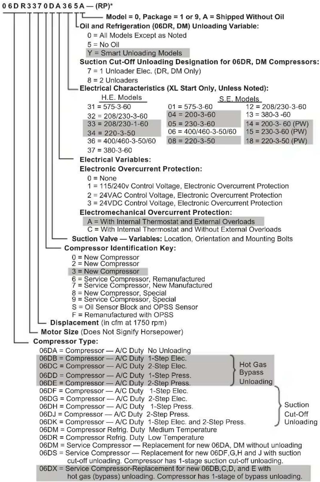
06D COMPRESSORS
*Refrigeration Partner
Information in shaded area is no longer available in standard factory production
06E COMPRESSORS
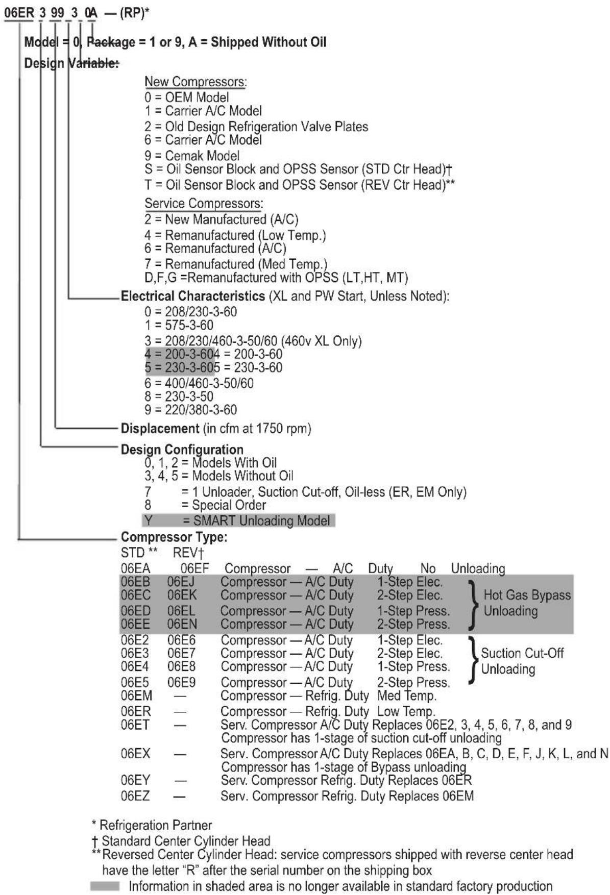
Design Variable:
101 = Single Pack, W/O Valves, with Oil
102 = Single Pack with Valves and Oil
103 = Single Pack, Service W/O Valves and Term. Box or Oil
201 = Single Pack, W/O Valves or Oil
202 = Single Pack with Valves
S = Oil Sensor Block and OPSS sensor (shown as the 10th digit)
Electrical Characteristics:
A = 415-3-50, XL and PW
B = 415-3-50, XL
C = 415-3-50, PW
D = 208/230-3-60, XL
E = 208/230/400/460-3-50/60
F = 400/460-3-50/60, XL and PW
G = 400/460-3-50/60, XL
H = 400/460-3-50/60, PW
J = 575-3-60, XL and PW
K = 230-3-60, PW
L = 220-3-50, XL and PW
M = 220-3-50, XL
N = 220-3-50. PW
P = 220/346/380-3-50/60, XL and PW
Q = 380-3-60. XL
Displacement (in cfm at 1750 rpm) (See Note below)
Motor Size and Protection:
5th Digit Motor Size
Overload Variable
| 0 = 15 FT-LB / 5 HP | Electromechanical Overcurrent Protection (*No Longer Available) |
| A = 15 FT-LB / 5 HP | 115/240V Control Voltage, Electronic Overcurrent Protection |
| B = 15 FT-LB / 5 HP | 24V AC Control Voltage, Electronic Overcurrent Protection |
| C = 15 FT-LB / 5 HP | 24V DC Control Voltage, Electronic Overcurrent Protection |
| 1 = 20 FT-LB / 6.5 HP | Electromechanical Overcurrent Protection (*No Longer Available) |
| D = 20 FT-LB / 6.5 HP | 115/240V Control Voltage, Electronic Overcurrent Protection |
| E = 20 FT-LB / 6.5 HP | 24V AC Control Voltage, Electronic Overcurrent Protection |
| F = 20 FT-LB / 6.5 HP | 24V DC Control Voltage, Electronic Overcurrent Protection |
| 2 = 24 FT-LB / 7.5 HP | Electromechanical Overcurrent Protection (*No Longer Available) |
| G = 24 FT-LB / 7.5 HP | 115/240V Control Voltage, Electronic Overcurrent Protection |
| H = 24 FT-LB / 7.5 HP | 24V AC Control Voltage, Electronic Overcurrent Protection |
| J = 24 FT-LB / 7.5 HP | 24V DC Control Voltage, Electronic Overcurrent Protection |
| 3 = 24 FT-LB / 7.5 HP | Electromechanical Overcurrent Protection (*No Longer Available) |
| K = 24 FT-LB / 7.5 HP | 115/240V Control Voltage, Electronic Overcurrent Protection |
| L = 24 FT-LB / 7.5 HP | 24V AC Control Voltage, Electronic Overcurrent Protection |
| M = 24 FT-LB / 7.5 HP | 24V DC Control Voltage, Electronic Overcurrent Protection |
| 5 = 45 FT-LB / 15 HP | Not Factory Installed, External Overcurrent Protection Required |
| 6 = 60 FT-LB / 20 HP | Not Factory Installed, External Overcurrent Protection Required |
| 7 = 75 FT-LB / 25 HP | Not Factory Installed, External Overcurrent Protection Required |
| 8 = 90 FT-LB / 30 HP | Not Factory Installed, External Overcurrent Protection Required |
Compressor Type:
06CC = Compound Cooling Model
06CY = Service Compressor
06C8 = Compressor, Special
Information in shaded area is no longer available in standard factory production.
NOTE: USE OF "cfm" AS MODEL SIZE DESIGNATION
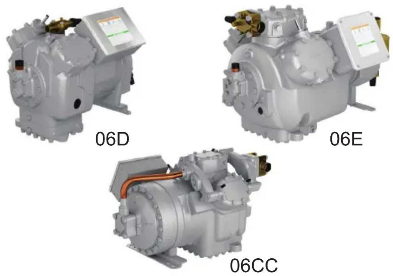
Carlyle uses the "cfm" designation in the model number to identify the compressor size. The cfm values are the sixth and seventh digits of the model number. See example above. Carlyle offers two series of compressors based on body size.
The smaller compressors, from 8 to 37 cfm, are referred to as "D" size units (model number "06D"). The larger compressors, from 50 to 99 cfm, are referred to as "E" size units (model number "06E").
The 06CC, or Compound Cooling compressors, are made in 16 to 37 cfm and 50 to 99 cfm sizes.
The 16 to 37 cfm compressors use "D" size bodies. The 50 to 99 cfm compressors use "E" size bodies.
NOTE: METRIC MEASUREMENTS
The compressors are built using English units: inches, foot-pounds, pints, etc. A corresponding metric measurement has been added to all the English units in this guide. These metric measures are a guide only, having been rounded to the nearest whole number, and therefore are not meant to be an exact mathematical conversion.
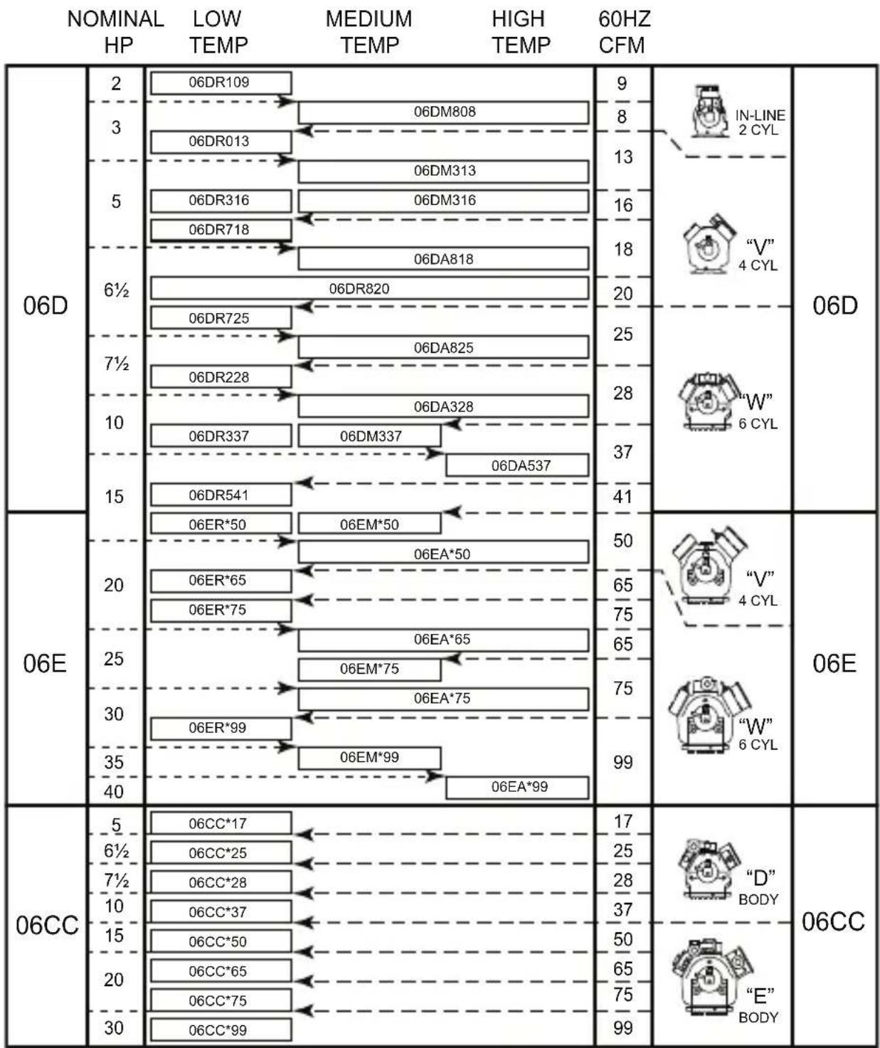
1.2 Application Range
other
| NOMINAL HP | LOW TEMP | MEDIUM TEMP | HIGH TEMP | 60HZ CFM | | ---------- | -------- | ----------- | --------- | -------- | | 2 | 06DR109 | | | 9 | | 3 | | 06DM808 | | 8 | | 5 | | 06DM313 | | 13 | | 6½ | | 06DR316 | | 16 | | 7½ | | 06DR718 | | 18 | | 10 | | 06DR820 | | 20 | | 15 | | 06DR725 | | 25 | | 20 | | 06DR228 | | 28 | | 25 | | 06DR337 | | 37 | | 30 | | 06DR541 | | 41 | | 35 | | | | | | 40 | | | | | | 5 | 06CC*17 | | | 17 | | 6½ | 06CC*25 | | | 25 | | 7½ | 06CC*28 | | | 28 | | 10 | 06CC*37 | | | 37 | | 15 | 06CC*50 | | | 50 | | 20 | 06CC*65 | | | 65 | | 30 | 06CC*75 | | | 75 | | | 06CC*99 | | | 99 | The image displays a schematic representation of the chart. It includes labels for the numbers '06D' and '06E' in the top row and '06CC' in the bottom row. The numbers 'IN-LINE' and '“V”' are shown above the chart, while 'W' and 'W' represent the positions of the lines. The 'E' label is also shown on the right side.Fig. 1 — 06DE/CC HP CFM
1.3 — Nameplate Significance
MANUFACTURING NUMBER BAR CODE MANUFACTURING NUMBER
ELECTRICAL CHARACTERISTICS SERIAL NUMBER BAR CODE SERIAL NUMBER
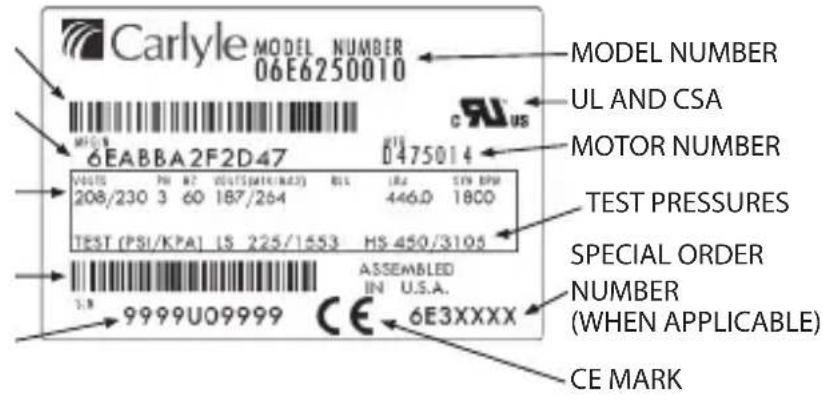
Explanation of the above items, starting clockwise from upper right:
MODEL NUMBER - Used when selecting and ordering a replacement compressor. Distributors use the model number to obtain a proper service replacement.
NOTE: Model numbers on some compressors are identified by the symbol “M/N” located in the upper right hand corner of the nameplate.
UL AND CSA - Single mark indicates that this compressor meets all the requirements for both UL (Underwriters Laboratory) and CSA (Canadian Standards Association). All 60 Hz semi-hermetic Carlyle Compressors are UL and CSA recognized and comply with UL, CSA, and NEC (National Electrical Code) requirements for internal motor protection.
MOTOR NUMBER - For Carlyle internal use only.
TEST PRESSURES - Each Carlyle 06D,E,CC compressor is pressure tested at our factory. The “LS” pressures are for the low side of the compressor. The “HS” pressures are for the high side of the compressors.
SPECIAL ORDER NUMBER (WHEN APPLICABLE) - For Carlyle internal use only.
CE MARK - This CE Mark indicates this compressor complies with the European CE Mark requirements.
SERIAL NUMBER - The unique number given to each compressor. This number, along with the model number and special order number, is normally all that is needed to obtain information about or order a service replacement compressor.
SERIAL NUMBER BAR CODE - For Carlyle internal use only.
ELECTRICAL CHARACTERISTICS - Are shown for all semi-hermetic compressors. Voltages are shown with respective operating ranges for both 50 and 60 cycle operation. Electrical phase and LRA (Locked Rotor Amps) information is also provided.
MANUFACTURING NUMBER - For Carlyle internal use only.
MANUFACTURING NUMBER BAR CODE - For Carlyle internal use only.
1.4 — Compressor Serial Number Significance
ALL NEW COMPRESSORS
Example: S/N 3622C00123
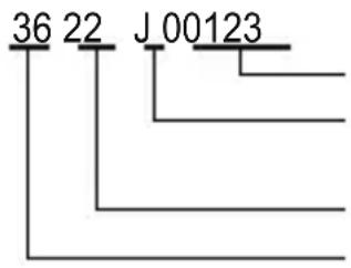
Numerical Sequence
Plant Location: J = Syracuse, U = Atlanta,
C=Monterrey, Z=Shanghai
Year of Manufacture: 20, 21, 22, etc.
Week of Manufacture: 01 thru 52 Begin Jan.1st
ALL SERVICE COMPRESSORS
Example: S/N 3622GD0123
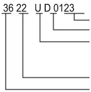
Numerical Sequence
Compressor Type: D, E
Plant Location: M = Atlanta, P = Phoenix,
U = Atlanta (from 4/2021 thru 11/2021)
G=CMP Mtn (after 12/2021)
Year of Manufacture: 20, 21, 22, etc.
Week of Manufacture: 01 thru 52. Begin Jan. 1st
NEW AND SERVICE REPLACEMENT
COMPRESSORS BUILT BETWEEN
NOV. 1968 - OCT. 1978
Example: A2J0001
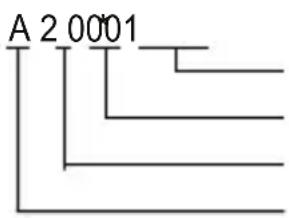
Numerical Sequence
Plant Location: J = Syracuse
Year of Manufacture: 9=69, 0=70, 1=71, etc.
Month of Manufacture: A=Jan, B=Feb, etc.;
skip I; M=Dec
*An "X", "A", or "P" in this location indicates a remanufactured service compressor. A number indicates a new production model.
1.5 — Carlyle OEM Compressor Warranty
Original OEM compressors are warranted to be free from defects in material and workmanship for a period of 12 months from the date of original installation, or 20 months from the date of manufacture, whichever comes first. Terms and conditions of the compressor warranty are specified in the list price pages.
When a service compressor is used to replace an original compressor, the remaining portion of the first-year OEM warranty is transferred to the service compressor (within the United States and Canada).
Equipment may carry an extended OEM warranty if that warranty has been purchased from the OEM. The OEM issues the extended warranty, not Carlyle or its distributors, and the OEM is responsible for providing the end user with the credit.
If returning a compressor:
- place all parts back into compressor
- seal all compressor openings (oil leakage may create an environmental hazard)
NOTE: Opening a compressor for observation or determination of failure does not void warranty.
1.6 — Service Billing and Credit
Returns of in-warranty parts should be made to the same Local Caryle Distributor who supplies these replacement parts.
Local Carlyle Distributors will sell parts and service compressors only to credit-approved accounts (except for cash sales).
1.7 — Carlyle Service Replacement Compressors, Parts, and Support
Carlyle service replacement compressors, parts, and support are available through a wide distribution network.
Technical support is provided by your local distributor. Customer Service Representatives can provide assistance in locating your nearest distributor.
In the USA, contact your nearest Carlyle distributor.
Locate your distributor at
https://www.rchvacparts.com/dealers/tools/distributor-locator
In Canada, contact your nearest WWG Totaline branch location, or online at
https://www.carrierenterprise.ca/contact
Locate your branch at
https://www.carrierenterprise.ca/branches
In Mexico, contact your nearest Totaline branch location.
Locate your branch at https://www.totaline.com.mx/contact/
2.0—START-UP, TROUBLESHOOTING, AND SERVICE
2.1 — Technical Assistance - Carlyle OEM Compressors
Carlyle Compressor Division sells compressors to OEMs (Original Equipment Manufacturers) that design and build the finished system. The OEM is the expert on the entire system, including the Carlyle compressor. All system or compressor questions should be directed first to the OEM or the OEM's local representative. If questions cannot be answered by the OEM or this Service Guide, please contact the Carlyle engineering group.
The following recommended start-up procedure for Carlyle 06D, 06E, and 06CC compressors will help eliminate initial compressor failures caused by flooded start, floodback, and running out of oil.
The Troubleshooting Procedures section (Section 2.3, pages 23 to 34) will help pinpoint compressor and system problems.
The Service Procedures section (Section 2.4, pages 35 to 46) covers the replacement of valve plates and gaskets, service to the bearing head assembly containing the oil pump, and a clean-up procedure to follow in case of motor burnout. Most other internal service requires replacement of the compressor.
2.2 — Recommended Start-Up Procedure

CAUTION
Do not add excess oil. It is especially important on the 06E and 06CC (50 to 99 cfm) compressors that excess oil not be added to the system. Laboratory tests and field experience indicate excessive oil levels can cause blown valve plate and cylinder head gaskets, increase compressor operating temperatures, and cause oil equalization problems.
NOTE: Scan QR codes below for link to start-up and installation instructions on the Carlyle literature website.
06D

574-067 06D Installation Instructions for 06D Compressor
https://www.shareddocs.com/hvac/docs/2002/Public/04/574-067.pdf
06E

574-068 06E Installation Instructions for 06E Compressor
https://www.shareddocs.com/hvac/docs/2002/Public/03/574-068.pdf
06CC (16-37 cfm)

570-849 06CC Installation Instructions for 06CC (16-37 cfm) Compressor
https://www.shareddocs.com/hvac/docs/2002/Public/0D/570-849.pdf
06CC (50-99 cfm)

570-850 06CC Installation Instructions for 06CC (50-99 cfm) Compressor
https://www.shareddocs.com/hvac/docs/2002/Public/07/570-850.pdf
Parallel compressor applications typically use an oil-control float system consisting of individual floats, a separator and an oil reservoir. When using a float system, do not interconnect the floats with an “equalization system” without approval from Carlyle application engineering. The use of a float “equalization system” can result in system oil control problems.
An oil equalization line can be used instead of a float system, except with 06CC compressors. The equalization line and the compressors must be level, and the line diameter must be large enough to allow both the refrigerant and oil to equalize between all the interconnected compressors. If the line is not level, it is undersized, or the system contains too much oil, the oil level will rise filling the line, and oil control between compressors will be lost. Typically, equalization lines are 1-1/8 in. (28 mm) in diameter or larger. For 06D compressors, a sight glass in the line is required to determine the system oil level.
Parallel systems using three (3) or more 06E compressors require the use of a common motor barrel interconnection line between compressors. Use of an interconnection line is strongly recommended on two (2) 06E compressor unit configurations. This system prevents oil from building up in an 06E motor barrel during the off cycle, thereby preventing an oil slug on start-up. The line is either 1/4 in. (6 mm) or 3/8 in. (8 mm) tubing inter-connecting to fitting located in the bottom of the 06E crankcases. To connect the 06E compressor motor barrel, fitting P/N 5F20-1311 (5/8 in. -18 x 1/4 in. NPT) with AU51YA011 gasket is recommended. Some 50 cfm compressors have a 1/4 in. NPT connection and do not require the 5F20-1311 fitting.
The motor barrel inter-connection line is in addition to either the crankcase oil equalization line or the oil floats.
Never interconnect the motor barrels of 06CC compressors, as the oil sump of these compressors are at intermediate pressure.

CAUTION
06E compressors will not tolerate excessive oil charges. Laboratory tests and field experience confirm that excess oil, especially in 06E compressors, can cause cylinder head gaskets and valve plates to fail, increase compressor operating temperatures, and lead to oil control problems. Page 15, Section 2.2 notes the correct oil levels.

CAUTION
Do not charge oil through the suction line or through the compressor suction access fittings. See the compressor figures in Section 2.5 for the location of the recommended oil charging ports. Adding oil into the suction side of the compressor can result in oil intake directly into the cylinders resulting in suction/discharge valve, piston and/or connecting rod damage.
COMPRESSOR START-UP
-
After circuit breaker and control circuit switches are placed in the ON position and the compressor starts, listen for unusual sounds. If unusual sounds are heard, shut down the compressor, investigate the cause, and correct. Possible problems are:
-
Excessive vibration
- Excessive oil
- Liquid slugging
-
Low oil
-
After the compressor has run 10 to 15 minutes and no liquid floodback is evident, completely open suction service valve. The other compressors within the system should be started in the same manner.
- To ensure operating oil levels are within acceptable limits, closely observe the oil level in the compressors until the system has stabilized. During operation all refrigeration systems will lose some compressor oil to the system because:
- All systems have a film of oil on the inside surface of the piping. At start-up, the lines are dry and the oil which coats the lines comes from the compressor crankcase.
- Oil also traps in the low refrigerant velocity area of the system and must be made up by adding oil to the system. On systems with hot gas defrost, inspect the compressor for excessive oil after the defrost cycle has been completed.
The oil lost to the system must be replaced, but make sure not to add too much. The 06E and 06CC (50 to 90 cfm) compressors have been successfully started in supermarket
refrigeration configurations by adding only 1 quart (liter) of additional oil per compressor. The amount to be added will vary depending on the system, but keeping the oil level between 1/8 and 3/8 level in the sight glass will eliminate the chance of excessive oil charges.

CAUTION
Adding excessive oil to the 06E and 06CC (50 to 99 cfm) compressors can cause blown gasket problems.

CAUTION
Liquid refrigerant should never be allowed to flood back to the compressor. It may wash out bearings and damage gaskets. If liquid floodback is occurring, adjust the expansion valve or make other adjustments as necessary to eliminate this condition.
NOTE: One possible cause of flooding is improper control of the defrost cycle. Ensure defrost cycles are staggered so no more than one third of the system is on defrost at any time.
COMPRESSOR OPERATING LIMITS
Figures 2 and 3 show the components and typical operating ranges of the Carlyle 06D, E, and 06CC compressors.
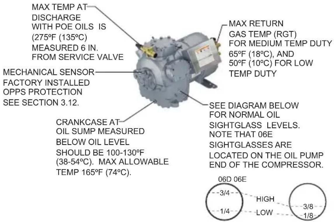
Fig. 2 — Typical 06D, E Operating Limits
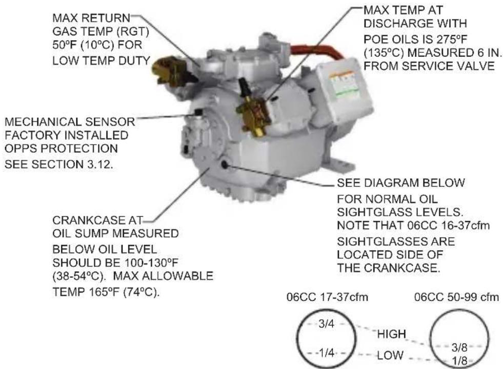
Fig. 3 — Typical 06CC Operating Limits
2.3 — Troubleshooting Procedure

DANGER
Before attempting service work on the compressor, the following safety precautions must be strictly observed. Failure to follow these instructions could result in serious personal injury or death. See warning label.
Follow recognized safety practices and wear protective goggles.
Do not operate compressor or provide electric power to this unit unless the compressor terminal box cover is in place and secured.
Do not provide power to unit or turn on compressor unless suction and discharge service valves are open. When not operating keep at least one service valve open unless replacing the compressor.
Do not remove the compressor terminal box cover until all electrical sources have been disconnected.

DANGER
When leak-testing semi-hermetic compressors, check around the terminal box cover. Test around the wire entry point(s) of the cover because refrigerant is likely to concentrate there. Do not remove the terminal cover to perform this leak testing because bodily injury or death can result from fire and/or explosion if cover is removed or unsecured before power is disconnected and pressure is relieved. Electrical terminal pins may blow out, causing injury and fire.
COMPRESSOR ISOLATION
If you have determined there is no refrigerant leak around the terminals and the compressor must be replaced, proceed beginning with Step 1:
-
Shut off suction and discharge service valves to isolate compressor and slowly remove all refrigerant in compressor. Appropriate service practices should be followed to properly reclaim refrigerant removed from the compressor.
-
Disconnect all electrical wiring to compressor.
-
Unbolt suction and discharge service valves from compressor.
REMINDER: These valves may be sealing off refrigerant from the rest of the system. Do not open these valves without first determining whether there is refrigerant in the system.
Troubleshooting Guide - 06D, 06E and 06CC Compressors
| OBSERVATION POSSIBLE CAUSE REMEDY | ||
| 1. Compressor will not start Power off. Check main switch, fuses and wiring. | ||
| Overcurrent protection open. Reset manually. | ||
| Oil safety switch open. Reset manually. | ||
| Loose electrical connections or faulty wiring. Tighten connections. Check wiring and rewire if necessary. | ||
| Compressor motor burned out. Inspect and replace compressor if defective. | ||
| 2. Low compressor capacity or inability to pull down system | Broken connecting rods or pistons. Replace compressor. | |
| For 06CC only: Blown valve plate or cylinder head gasket. | See No. 3 | |
| Leaky valve plates or worn valve seat. Replace valve plate assembly. | ||
| Leaky or broken suction valves. Pump down, remove cylinder head, examine valves and valve seats. Replace if necessary. | ||
| Check pressure difference between suction, interstage and discharge if: a.pressure is low between suction and interstage.b.pressure is low between interstage and discharge. | a. Check for problems in low stage heads.b. Check for problems in high stage head. | |
| 3. Blown valve plate or cylinder head gaskets | Cylinder head bolts not properly torqued. a. Replace gasketsb. Retorque cylinder head bolts to:06D and 06CC (16 to 37 cfm):30 to 35 ft-lb (40 to 48 Nm)06E 100 06CC (50 to 99 cfm):90 to 35 ft-lb (122 to 136 Nm) | |
| Excessive oil in 06E and 06CC (50 to 99 cfm) compressors causes hydraulic cylinder pressures. | a. Remove excessive oil until oil level maintained between 1/8 to 3/8 up the sight glass.b. On multiple 06E compressor units, add motor barrel oil equalization line.NOTE: Do not use a motor barrel oil equalization line with 06CC compressors. | |
| Liquid refrigerant floodback or flooded start. See No. 7 (Flooding). | ||
| 4. Compressor cycles intermittently | Low-pressure switch erratic in operation. | a. Check tubing to switch to see if clogged or crimped.b. Verify proper setting of switch. |
| Insufficient refrigerant in system. Add refrigerant. | ||
| Suction service valve closed. Open valve. | ||
| Insufficient water flowing through condenser or clogged condenser. | a. Adjust water regulating valve to condenser b. Clean condenser. | |
| Discharge service valve not fully open. Open valve. | ||
| Air in system. Recover and recharge refrigerant per refrigerant manufacturer's recommendations. | ||
| OBSERVATION | POSSIBLE CAUSE | REMEDY |
| 5. Compressor continually cycles Faulty pressure | surestats. Repair or replace. | |
| Dirt or restriction in tubing to pressurestat. Check and clean tubing. | ||
| Condenser capacity reduced by refrigerant over-charge accompanied by high discharge pressure. | Remove excess refrigerant. | |
| Plugged filter-drier. Replace filter. | ||
| 6. Low discharge pressure | Excessive water flow through condenser. | Adjust water regulating valve. |
| Suction service valve partially closed. Open the valve. | ||
| Leaky compressor suction valves. Pump down, remove the cylinder head, examine valves and valve seats. Replace if necessary. | ||
| Worn piston rings. Replace compressor. | ||
| 7. Flooding Improper system piping allows liquid to compressor. | Correct piping. | |
| Defrost cycle improperly set or not operating correctly. | ||
| Defective or improperly set expansion valve. Increase superheat or replace valve. | ||
| Evaporator fan failure. Correct problem or replace fan. | ||
| 8. Low suction pressure | Insufficient refrigerant in system. | Add refrigerant. |
| Evaporator fan failure. Correct problem or replace fan. | ||
| 9. Compressor noisy Slugging due to floodback of refrigerant. See No. 7 (Flooding). | ||
| Hydraulic knock due to excess oil in circulation. a. | Remove excess oil.b. Recheck oil return system and pipe sizes. | |
| Bearings damaged because of loss of oil. a. Add oil (only after confirming all system oil has returned to the compressor).b. Check oil return system and piping size.c. See No. 15 (Parallel Systems Oil Level) and No. 11 (Oil Pressure).d. Check for defective oil failure control. | ||
| Improper support or isolation of piping. Provide | sufficient right angle bends in piping to absorb vibration and support firmly with suitable hangers. | |
| Compressor not firmly mounted. Check for loose mounts. | ||
| Unit not properly isolated or vibration pad defective. | Add vibration isolation or check for defective isolation pads. | |
| Broken connecting rods, valves or other running gear | Replace compressor. | |
| 10. Pipe rattle Inadequately supported piping or loose pipe connections. | a. Support pipes and/or check pipe connections.b. Add muffler or baffle plate. | |
| 11. Oil pressure lower than normal or no oil pressure. | Low oil charge. Verify oil level requirements. | |
| Faulty oil pump drive segment. Replace segment. | ||
| Refrigerant floodback. | See No. 7 (Flooding). | |
| Desuperheating TXV stuck open. | Replace TXV. | |
| Worn oil pump. | Replace bearing head assembly. | |
| Worn compressor bearings. | Replace compressor. | |
| OBSERVATION POSSIBLE CAUSE REMEDY | ||
| 12. Compressor motor protectors or discharge temperature sensor tripping or cycling. | High suction pressure on low temperature compressor causes excessive amp draw. | If system does not have EPR valve, throttle suction service valve until system pulls down. |
| High discharge pressure. Check for loss of condenser water, blocked condenser fan or coil, or defective fan motor. | ||
| Incorrect overload relay or must trip amp setting too low. | Replace with correct overload relay. | |
| Detective overload relay or circuit breaker. Replace. | ||
| High suction temperature. Reduce suction temperature by TXV adjustment or provide desuperheating. | ||
| Loose power or control circuit wiring connection. | Check all power and control circuit connections. | |
| Defective motor. Check for motor ground or short. Replace compressor if found. | ||
| Faulty motor protection device. On all 06E and 06CC compressors, check the thermal sensor in the cylinder head. Replace head sensor if necessary. | ||
| High compression ratio (suction too low/condensing too high): return gas temperature above application limits. | Adjust compressor operational envelope. | |
| For 06CC compressors only: Broken valve on high stage or blown high stage gasket. | Repair compressor. | |
| Insufficient desuperheating. Adjust desuperheating valve. | ||
| 13. Compressor cycles on locked rotor | Low line voltage. | Measure line voltage and determine location of voltage drop. |
| Seized compressor (remove bearing head assembly and attempt to rotate crankshaft). | Replace compressor. | |
| Compressor motor defective. Check for motor winding short or ground. | ||
| Single phasing. Measure voltage across all 3 legs at contactor. Correct source of problem. | ||
| Liquid refrigerant condensing in cylinder. Check and replace valve plates. | ||
| On part-winding start compressors, the second set of windings may not be energized. | a. Faulty contactor – replace.b. Faulty time-delay relay – replace. | |
| 14. Motor Burnout Inspect control box for welded starter contacts, welded overload contacts, or burned out heater elements. | Replace defective components and compressor. Check refrigerant and oil for contamination and clean to prevent repeat failure. | |
| Replace compressor. Check refrigerant and oil for contamination and clean to prevent repeat failure. | ||
| 15. On parallel compressor installations, oil level does not equalize or remain at a constant level in all compressors | Oil equalization line not level, preventing gas equalization.NOTE: Oil equalization lines cannot be used with 06CC compressors. A float system must be used. | Level oil equalization line. |
| 06E Compressors Only:Pressure equalization check valve in the motor rotor lock bolt may have been left out in one or all compressors.NOTE: Check valve not required with float system. | Remove suction service valve and look for check valve in motor rotor lock bolt at the end of the crankshaft. Check valve is required on all 06E compressors in systems using the oil equalization line connected at the sight glass location. | |
| Excessive blow-by into crankcase - worn rings, valves or blown gasket. | Replace gasket, valve plate, or compressor. | |
| Improper suction line sizing. Resize lines. | ||
| Oil reservoir check valve bad or wrong pressure. | Replace check valve; 20 psi check valve required. | |
| With Float System:Oil is not equalized in sight glass. | a. Check floats. Replace detective floats.b. Check for proper selections and settings:-06D and 06CC (16 to 37 cfm) - 1/4 to 3/4 sight glass.-06E and 06CC (50 to 90 cfm) -1/8 to 3/8 sight glass.c. If floats have equalization line, the line between the floats may have to be removed. Contact Carlyle engineering. | |
| 16. Compressor running hot | Blown valve plate or cylinder head gasket. | Blown valve plate or cylinder head gasket. |
| Broken suction or discharge valve. Broken suction or discharge valve. | ||
| Compression ratio too high. a. Verify proper setting of high and low pressure switches.b. Inspect for condenser plugging.c. Ensure all evaporator and condenser fans are operating properly. | ||
| High suction temperature. Reduce suction temperature by TXV adjustment or provide desuperheating. | ||
| Cylinder head cooling fan not operating or incorrect voltage for fan motor. | Replace defective part or verify available voltage agrees with fan motor voltage. | |
| 06E and 06CC (50 to 99 cfm) Compressors only:Non-seating internal pressure relief valve. | Check for signs of overheating, replace if necessary. | |
| High oil level. High oil level. | ||
| Excessive blow-by into crankcase - worn rings, valves or blown gasket. | Replace gasket. valve plate, or compressor. | |
| 17. Oil safety switch tripa.If sight glass appears emptyb.If sight glass appears normal | Faulty switch or oil pressure settingsNOTE: Never add oil to the system without first confirming that oil has been physically lost, not simply trapped in the system. Check oil levels after a defrost cycle. | Manually check for oil pressure. If correct, check that switch is correct model and has proper settings (see page 70, Section 3.12). |
| Oil trapped in the system.NOTE: At times, the sight glass may appear empty when actually it is completely full. | a. Check line sizing and risers for proper sizing to return oil.b. If floats are being used, check for proper setting and proper functionality. | |
| Liquid refrigerant in crankcase. a. Check for low superheats which can return refrigerant - raise superheat.b. Check for liquid migration during OFF cycle - provide a form of pumpdown protection. | ||
| For 06CC Compressors Only:18. High mid-stage pressure | Broken valve or blown gasket on the high stage. | Replace broken valves or gasket. |
| 19. Low mid-stage pressure Broken valve or blown gasket on the low stage. | Replace broken valves or gasket. | |
| 20. Economizer/Desuperheater connection hot | Broken valve on high stage. Replace broken valves. | |
| Blown high stage gasket. Replace gasket. | ||
| 21. Intermediate pressure equals the discharge pressure | Center low stage valve plate gasket is blown (typically caused by heavy liquid floodback or flooded start). | Eliminate floodback and replace gasket. |
| Compressor started with discharge service valve closed. | Open discharge service valve. | |
| High stage valve plate is on the low stage cylinder head. | Switch valve plates so high stage valve plate is on the high stage cylinder head. | |
| Internal relief valve loose. Tighten internal relief valve. | Valve. | |
| Internal relief valve blown. Replace internal relief valve. | Valve. | |
LEGEND
EPR — Evaporator Pressure Regulator
TXV — Thermostatic Expansion Valve
2.4 — Service Procedures
The service section covers replacement of valve plates and gaskets, service to the bearing head assembly containing the oil pump, and a clean-up procedure to follow in case of motor burn out. Most other internal service requires replacement of the compressor.
REMOVE, INSPECT AND REPLACE CYLINDER HEAD AND VALVE PLATE ASSEMBLY
To test for leaking discharge valves or blown cylinder head or valve plate gaskets:
- Pump compressor down.
- Observe suction and discharge pressure equalization. If valves are leaking or a gasket is blown, the pressure will equalize rapidly.
Maximum allowable discharge pressure drop is 3 psi per minute after initial drop of 10 to 15 psi in first half minute.
New reed valves may require 24 to 48 hour run-in time to seat completely.
A compressor bank (head) with a blown gasket can also usually be detected by touch since the head temperature will normally be much hotter than a bank with good gaskets.
- If there is an indication of loss of capacity and discharge valves are functioning properly, remove valve plate assembly and inspect suction valves.
NOTE: This test procedure is not applicable to compressors equipped with pressure actuated unloader valves due to rapid pressure equalization rate. Inspect suction and discharge valves by disassembling valve plate.
DISASSEMBLY
- Disassemble cylinder heads by removing cylinder head bolts. Leave at least two bolts partially threaded to prevent any problems if refrigerant is accidentally left in the compressor under pressure. To separate the cylinder head from the valve plate, pry up between the head and valve plate. When the cylinder head is separated from the compressor body remove the last threaded bolts.

CAUTION
Do not hit the cylinder head to break it free of the valve plate. This may shear the valve plate dowel pins. Sheared dowel pins usually require the compressor to be replaced.
- Inspect cylinder heads for warping, cracking, or damage to gasket surfaces. Replace if necessary.
- After the cylinder head is off, the valve plate may be removed as follows:
a. Remove one valve stop cap screw and loosen the other.
b. Swivel valve stop to allow access to hole from which the cap screw was removed.
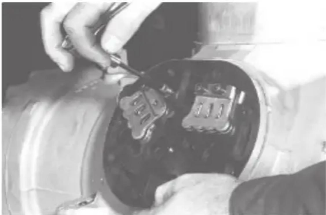
c. Re-insert cap screw and tighten to break valve plate away from compressor. (Jack screw method, see Fig. 4.) For 06E valve plates, pry against the raised tab to break valve plate away from the compressor.
natural_image
Close-up of hands working on a mechanical component with two metallic components (no visible text or symbols)Fig. 4 — Disassembly of Valve Plate (Standard Efficiency Valve Plate Shown)
- Pry up along sides of valve plate to remove valve plate from crankcase. This provides access to suction reed valves (see Fig. 5). Remove suction valves from dowel pins. On 06D and 06CC (16 to 37 cfm) compressors, also remove the suction valve positioning springs (see Fig. 6).
- Inspect components for wear or damage. If replacement is necessary, replace as a complete assembly. Individual parts must not be interchanged. Alignment of high efficiency discharge valves is critical for proper seating. See Section 3.21 to 3.23, pages 94 to 96, for applicable replacement valve plate packages.
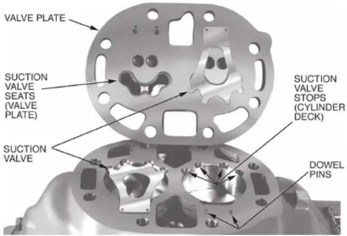
Fig. 5 — Valve Plate Removed (06E Refrigeration Valve Plate Shown)
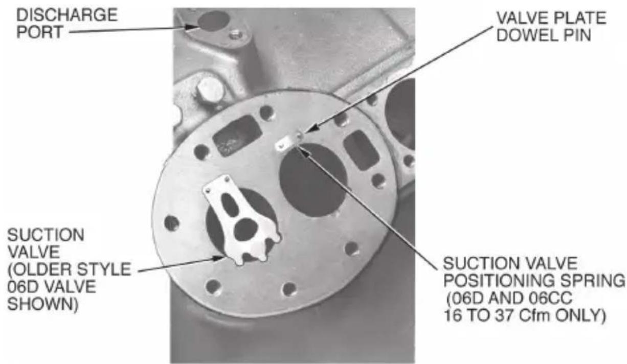
Fig. 6 — Suction Valve and Positioning Springs in Place (06D Shown)
REASSEMBLY
- If reassembling existing components, do not interchange valves or turn them over. They must be reassembled in their original position. Install the suction valve positioning springs (06CC size 16 to 37 cfm and 06D compressors only) on dowel pins. Assemble positioning springs with spring ends bearing against cylinder deck (Fig. 6), spring bow upward.
- Install suction valve on dowel pins as follows:
a. 06D Compressors: Install suction valves on top of positioning springs as mentioned in Step 1 above.
b. 06E Compressors: If compressor uses a suction valve and a backer valve (looks like half a suction valve), backer valve must be installed before installing full size suction valve (Fig. 7).
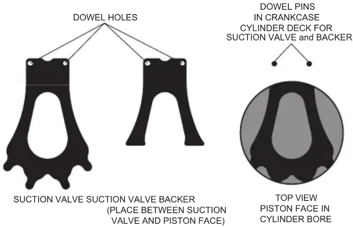
Fig. 7 — Piston, Suction Valve, and Backer Positions (06E)
- Install new valve plate gasket. Using proper hold-down torque will prevent leaks.
a. Fiber gaskets can be installed dry or lightly oiled. Do not soak gaskets in oil. If an oil-soaked gasket is overheated, it will bind to the metal, making the valve plate and/or the head difficult to remove.
b. Metal gaskets must be installed dry.
-
Place valve plate on cylinder deck.
-
Install cylinder head gasket.
NOTE: The center cylinder heads and unloader side heads use different gaskets from the plain side head. To confirm the gasket is correct, place it over the cylinder head and verify all exposed machined surfaces will be covered by the gasket.
a. Line up the gasket with the cylinder head and valve plate.
b. 06E Compressor: Secure the center rib with a cap screw and washer and torque to 4 to 6 ft-lb (5 to 8 N m).
- Replace cylinder head. To prevent high to low side leak in center of cylinder head gasket, torque 06D cylinder head cap screws to 30 to 35 ft-lb (40 to 48 Nm), and 06E cylinder head cap screws to 90 to 100 ft-lb (122 to 136 Nm).
NOTE: Torque bolts in an alternating sequence pattern (top to bottom, left to right). Do not torque bolts in a circular pattern.
- Certain high compression ratio applications develop high discharge gas temperatures which may cause the cylinder head and fiber valve plate gaskets to develop a set. Under these conditions the cap screws may lose hold-down torque. It is recommended that all gear cap screws be re-torqued 24 hours after new fiber gaskets are installed.
NOTE: Compressors with metal core gaskets do not require re-torque.
REMOVE, INSPECT AND REPLACE BEARING HEAD ASSEMBLY
An oil pressure tap is located in the bearing head assembly used on all 06D refrigeration duty, newer 06D A/C duty, and all 06E refrigeration and A/C duty compressors (Fig. 8-10).
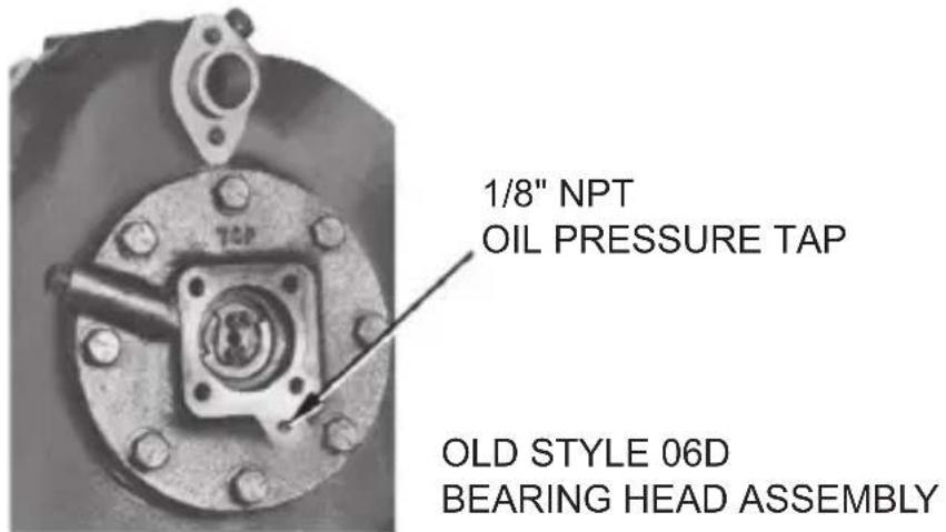
Fig. 8 — 06D Old Style Bearing Head Assembly
For 06D, E, CC oil pressure, see page 68, Section 3.7. The oil pump assembly is contained in the pump end bearing head aluminum casting. The pump end main bearing is a machined part of this casting. No insert bearing is required.
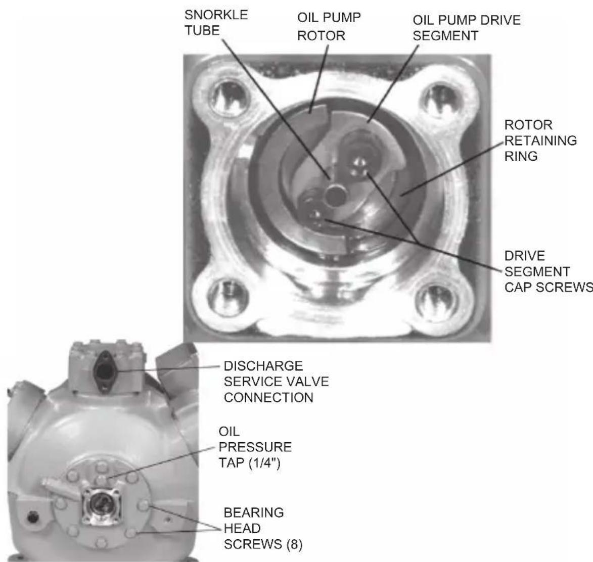
Fig. 9 — Removing Pump End Bearing Head (06D Compressor)
- To disassemble, first remove four (4) cap screws from the bearing head cover plate and remove the oil feed guide vane and spring.
Remove the two (2) drive segment cap screws from the end of the crankshaft (see Fig. 9 and Fig. 10).
These screws must be removed before the bearing head can be removed.
- Remove the eight (8) cap screws holding the bearing head assembly to the crankcase. Remove the bearing head assembly by pulling forward.
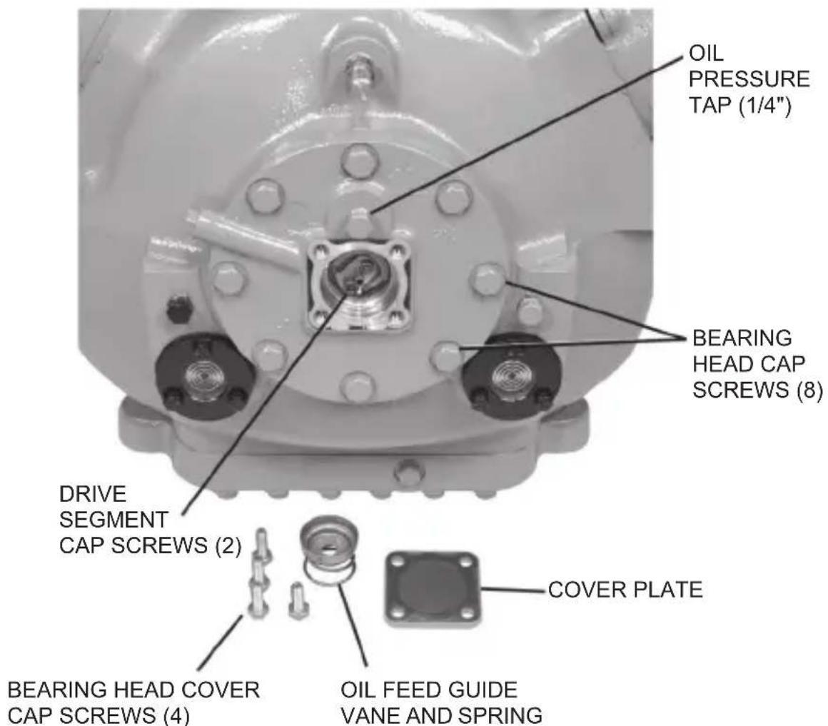
Fig. 10 — Removing Pump End Bearing Head (06E Compressor)
- Inspect the bearing surfaces for evidence of wear or damage. If bearing surface is worn or scored, or if the oil pump is defective, the complete bearing head must be replaced (see replacement bearing head package listed below).
| COMPRESSOR | REPLACEMENT BEARING HEAD PACKAGE |
| 06CC, 16 to 37 cfm, and all 06D | 06DA660126 |
| 06CC, 50 to 99 cfm, and all 06E | 06EA660157 |
While bearing head is removed, inspect internal running gear for obvious problems (broken rods or pistons).
-
To reassemble, bolt the bearing head to the crankcase. Bolt torque:
-
06CC, 16 to 37 cfm, and all 06D: 30 to 35 ft-lb (40 to 48 Nm)
-
06CC, 50 to 99 cfm, and all 06E: 50 to 60 ft-lb (75 to 81 Nm)
-
Bolt the drive segment (replace if worn) to the crankshaft. Bolt torque:
• No. 10 Screw: 4 to 6 ft-lb (5 to 8 Nm)
• 1.4 in. (6 mm) screw: 12 to 15 ft-lb (16 to 20 Nm)
IMPORTANT: The 1/4 in. snorkel tube should face away from the crankshaft (Fig. 9).
- Insert the oil feed guide vane with the large diameter inward. Place the oil feed vane spring over small diameter of guide vane (do not install spring before installing guide vane). Install pump cover plate (bolt torque: 16 to 20 ft-lb or 22 to 27 Nm).
NOTE: Do not over-torque or aluminum threads in bearing head could be stripped.
MOTOR BURNOUT CLEAN-UP PROCEDURE
When a hermetic motor burns out, the stator winding decomposes and forms carbon, water, and acid, which contaminate refrigerant systems. These contaminants must be removed from the system to prevent repeat motor failures.
Before attempting service work on the compressor, see safety precautions listed in Section 2.3 on page 24 and on compressor terminal box cover. Also follow any installation instructions provided with the replacement compressor. Failure to follow these instructions could result in equipment damage or serious personal injury.
- Determine cause of burnout and make necessary corrections.
a. Inspect control box for blown fuses, welded starter contacts, welded overload contacts or burned out heater elements.
b. Inspect compressor terminal plate for burned or damaged terminals and insulation, and shorted or grounded terminals.
c. Inspect unit wiring for loose power connections.
d. Check for power supply fluctuation beyond design limits (voltage too high or low). If power supply is a problem, provide the appropriate system protector.
- Close compressor suction and discharge service valves and remove the refrigerant from the compressor using environmentally approved methods. Leave remaining refrigerant in system.
- Remove damaged compressor and replace.
a. On severe motor burnouts, be sure shut-off valves and suction or discharge lines are not contaminated. If contaminated, thoroughly clean or replace before connecting replacement compressor.
-
Install new liquid line filter-drier. If the system has a suction line filter-drier, replace the core.
-
Evacuate and dehydrate replacement compressor. Ensure oil in compressor is at the proper level.
NOTE: Since most new and service compressors are now shipped without oil in the crankcase, you must check to see if there is oil. Adding or charging oil is usually easier prior to installing the compressor.
- If there is no oil, add the appropriate oil for the service. Oil charges are listed in Sections 3.1 (page 60) to 3.3 (page 64).
- If there is oil, determine if it is compatible with the refrigerant. If the oil is not compatible, use the drain connection to remove the oil. Dispose of the removed oil following the appropriate environmental guidelines. Since the compressor has not been run, a thorough draining is all that is needed to remain within the limits of residual oil levels. There is no need to “flush” the compressor with the replacement oil. Once the oil is removed, add the appropriate oil (see above).
- Place compressor in operation. After 2 to 4 hours of operation, inspect compressor oil for discoloration and/or acidity. If oil shows signs of contamination, replace oil and filter-driers and clean the suction strainer.
NOTE: When testing for moisture and acidity, be sure the test kit used is appropriate for the refrigerant (CFC, HCFC, or HFC) and the oil (mineral, alkylbenzene, or POE) in the system. Carrier's Total Test Kit is accurate for CFC and HCFC air-conditioning applications. If used with POE oils, Total Test Kit will indicate acid, but is not an accurate indicator of moisture.
- Inspect oil daily for discoloration and acidity. If oil stays clean and acid-free, the system is clean. If oil shows signs of contamination, change oil, change filter-drier, and clean suction strainer. If filter-drier or suction strainer is dirty or discolored, repeat this step until system is cleaned.
2.5 — Connection Points, 06D, 06E, and 06CC Compressors
NOTE: Bolt sizes and thread pitch: Compressors are built using English unit bolts. The bolts have no exact metric equivalents. Therefore, to prevent possible cross-threading, loose bolts, or damage to threaded portions of the casing, comparable metric measurements are not included. Refer to Fig. 11-15.
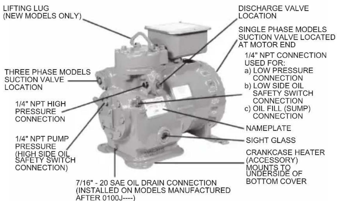
Fig. 11 — 06D 2-Cylinder Compressor Connection Points
NOTE: Cast bottom cover shown for 18 & 20cfm models. 13 & 16cfm models will have a stamped bottom cover with strap on crankcase heater.
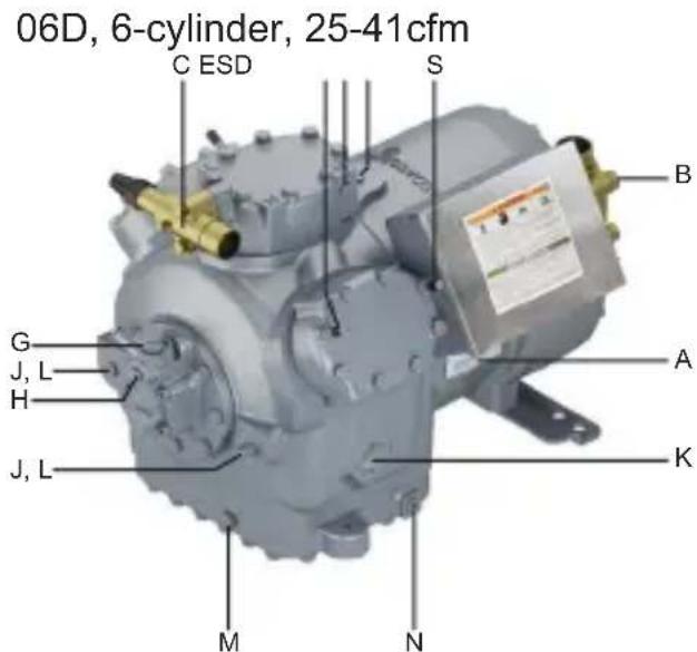
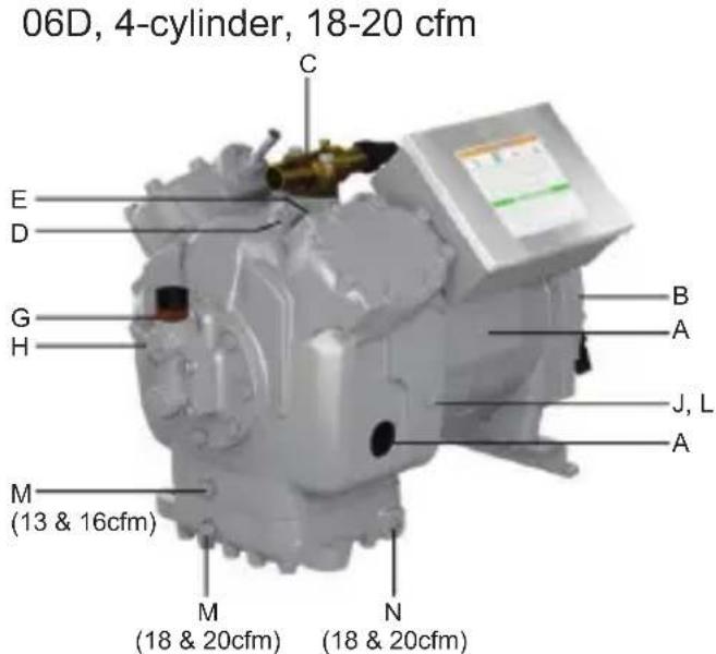
Connection Points
A Nameplate Location
B Suction Service Valve
C Discharge Service Valve
D Low Pressure Connection
E High Pressure Connection
G Oil Pressure Mechanical Sensor
H Oil Pressure Connection
J Low Side Oil Pressure Difference
K Oil Level Sightglass
L Oil Sump Fill Port
M Oil Sump Drain Port
N Crankcase Heater
S Cylinder Head Fan Studs
Fig. 12 — 06D Compressor Connection Points
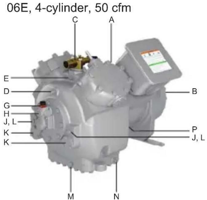
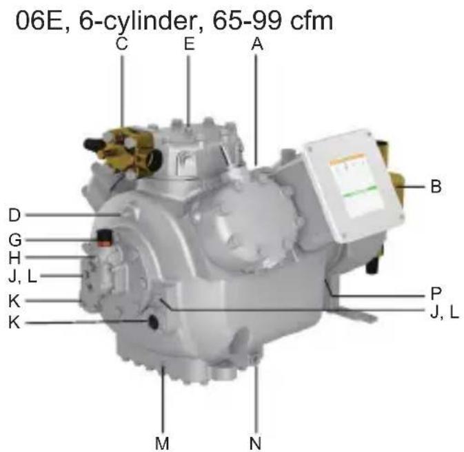
Connection Points
A Nameplate Location
B Suction Service Valve
C Discharge Service Valve
D Low Pressure Connection
E High Pressure Connection
G Oil Pressure Mechanical Sensor
H Oil Pressure Connection
J Low Side Oil Pressure Difference
K Oil Level Sightglass
L Oil Sump Fill Port
M Oil Sump Drain Port
N Crankcase Heater
P Motor Barrel Oil Equalization Drain
Fig. 13 — 06E Compressor Connection Points
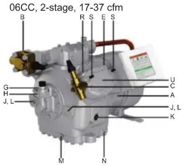
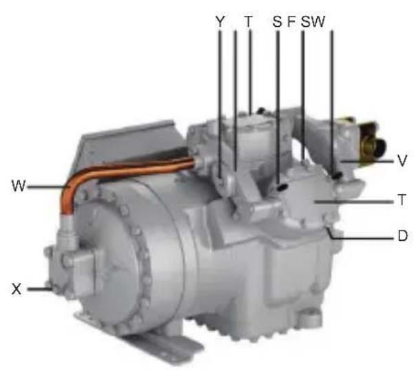
Connection Points
A Nameplate Location
B Suction Service Valve
C Discharge Service Valve
D Low Pressure Connection
E High Pressure Connection
F Interstage Pressure Connection
G Oil Pressure Mechanical Sensor
H Oil Pressure Connection
J Low Side Oil Pressure Difference
K Oil Level Sightglass
L Oil Sump Fill Port
M Oil Sump Drain Port
N Crankcase Heater
R Discharge Gas Temperature Sensor
S Cylinder Head Fan Studs
T 1st Stage Cylinder Head
U 2nd Stage Cylinder Head
V Suction Manifold
W Interstage Manifold
X Desuperheating Liquid Injection
Y Vapor Injection Flange
Fig. 14 — 06CC (D Body) Compressor (17 to 37 cfm) Connection Points
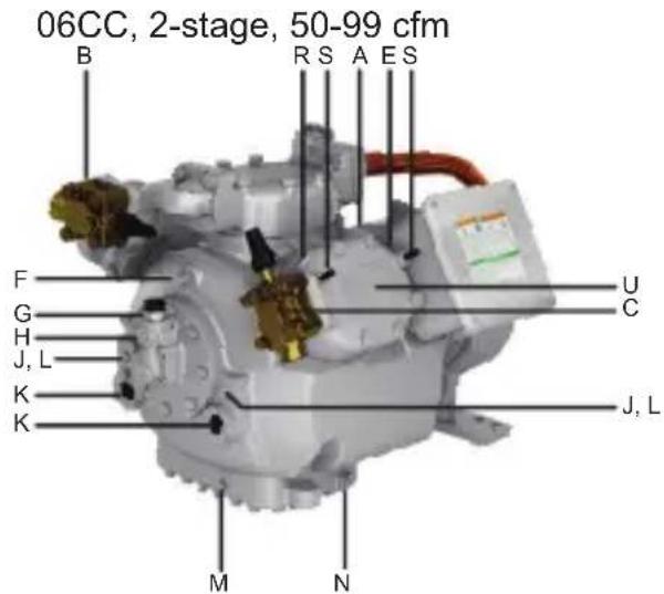
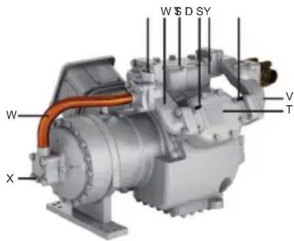
Connection Points
A Nameplate Location
B Suction Service Valve
C Discharge Service Valve
D Low Pressure Connection
E High Pressure Connection
F Interstage Pressure Connection
G Oil Pressure Mechanical Sensor
H Oil Pressure Connection
J Low Side Oil Pressure Difference
K Oil Level Sightglass
L Oil Sump Fill Port
M Oil Sump Drain Port
N Crankcase Heater
R Discharge Gas Temperature Sensor
S Cylinder Head Fan Studs
T 1st Stage Cylinder Head
U 2nd Stage Cylinder Head
V Suction Manifold
W Interstage Manifold
X Desuperheating Liquid Injection
Y Vapor Injection Flange
Fig. 15 — 06CC (E Body) Compressor (50 to 99 cfm) Connection Points
52
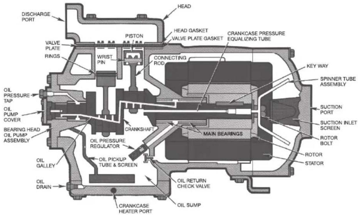
2.6 — Cross-Sectional View, 06D Semi-Hermetic Compressor
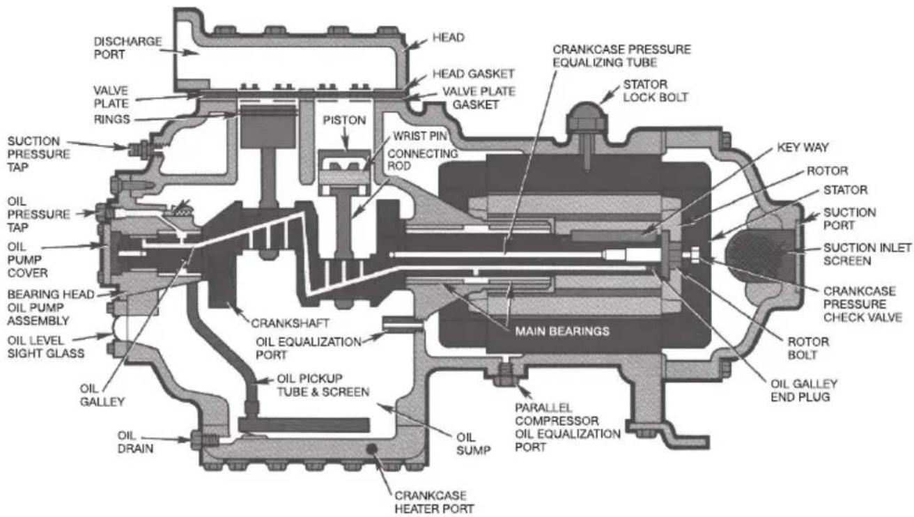
2.7 — Cross-Sectional View, 06E Semi-Hermetic Compressor
2.8 — Exploded View - 6-Cylinder 06D Compressor
Complete parts breakdown shown for reference only. Some parts may be pictured prior to design changes and not all parts are available as replacements.
LEGEND
2 — Terminal Box Cover
3 — Terminal Box
4 — Terminal Plate Assembly
9 — Grommet (for power leads)
14 — Suction Service Valve
15 — Suction Service Valve Seal Cap
16 — Suction Service Valve Gasket
17 — Suction Service Valve Bolt
18 — Suction Service Valve Bolt Washer
19 — Discharge Service Valve
20 — Discharge Service Valve Seal Cap
21 — Discharge Service Valve Gasket
22 — Discharge Service Valve Bolt
23 — Discharge Service Valve Bolt Washer
29 — Standard Side Bank Cylinder Head
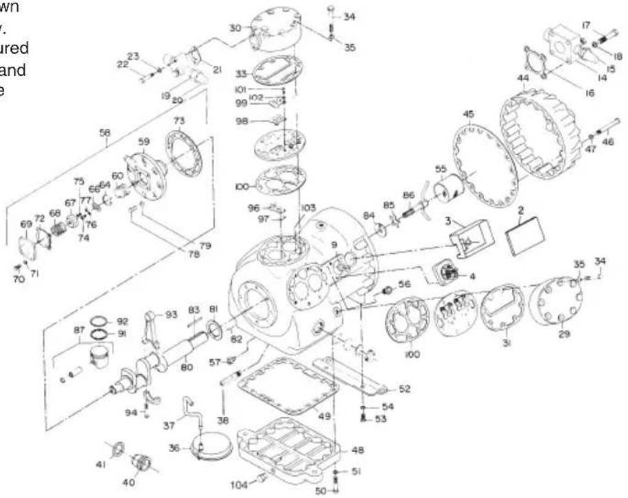
30 — Center Bank Cylinder
24 Standard Side Bank Cylinder Head Gasket (Unloader
31 — Side Bank Head not shown)
33 — Center Bank Cylinder Head Gasket
34 — Cylinder Head Cap Screw
35 — Cylinder Head Cap Screw Gasket
36 — Oil Filter Screen Assembly
37 — Oil Suction Tube
38 — Oil Relief Valve Assembly
40 — Oil Level Sight Glass Assembly
41 — Oil Level Sight Glass Gasket
44 — Motor End Cover
45 — Motor End Cover Gasket
46 — Motor End Cover Cap Screw
47 — Motor End Cover Cap Screw Washer
48 — Bottom Cover Plate
49 — Bottom Plate Gasket
50 — Bottom Plate Cap Screw
51 — Bottom Plate Cap Screw Washer
52 — Compressor Foot
53 — Compressor Foot Screw
54 — Compressor Foot Everlockwasher
55 — Suction Strainer Assembly
56 — Oil Bypass Plug
57 — Oil Return Check Valve Assembly
58 — Pump End Bearing Head Assembly
59 — Bearing Head
60 — Pump Rotor
64 — Pump Rotor Retaining Ring
66 — Drive Segment
67 — Oil Feed Guide Vane
68 — Oil Feed Vane Spring
69 — Cover Plate
70 — Cover Plate Cap Screw
71 — Cover Plate Cap Screw Gasket
72 — Cover Plate Gasket
73 — Bearing Head Gasket
74 — Cap Screws and Lockwashers
75 — Cap Screws and Lockwashers
76 — Cap Screws and Lockwashers
77 — Cap Screws and Lockwashers
78 — Bearing Head Cap Screw
79 — Bearing Head Cap Screw Washer
80 — Crankshaft
81 — Thrust Washer
82 — Spiral Pin
83 — Rotor Drive Key
84 — Rotor Washer
85 — Rotor Lockwasher
86 — Equalizer Tube Assembly
87 — Piston Assembly
91 — Oil Ring (Not All Models)
92 — Compression Ring
93 — Connecting Rod and Cap Assembly
94 — Connecting Rod Cap Screw
96 — Suction Valve
97 — Suction Valve Positioning Spring
98 — Discharge Valve
99 — Discharge Valve Stop
100 — Valve Plate Gasket
101 — Discharge Valve Stop Cap Screw
102 — Discharge Valve Stop Lockwasher
103 — Valve Plate Dowel
104 — Oil Drain Plug (New Design SAE Fitting and O-Ring)
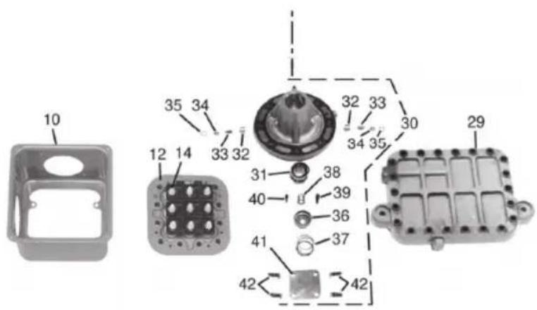
2.9 — Exploded View - 6-Cylinder 06E Compressor
Complete parts breakdown shown for reference only. Some parts may be pictured prior to design changes and not all parts are available as replacements.
LEGEND
1 — Compressor Motor - Stator and Rotor
2 — Motor Key
3 — Rotor Plate Washer
4 — Rotor Lock Washer
5 — Rotor Lock Bolt
6 — Motor Lock Bushing
7 — Roll Pin
8 — Acorn Nut and Gasket
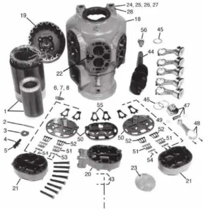
10 — Terminal Box Assembly
12 — Terminal Plate Assembly
14 — Terminal Bolt Assembly
18 — Compressor Crankcase
19 — Motor End Cover
20 — Cylinder Head - Center Bank
21 — Cylinder Head - Side Bank (Unloader Head Not Shown)
22 — Internal Relief Valve
23 — Crankcase Oil Filter Screen
24 — Oil Sight Glass Assembly
25 — Oil Sight Glass "O" Ring Gasket
26 — Oil Sight Glass Screw
27 — Oil Sight Glass Lock Washer
28 — Pipe Plug Gasket (Hex Head)
29 — Bottom Cover Plate
30 — Pump End Bearing Head Assembly
31 — Pump Rotor
32 — Pump Vane
33 — Pump Vane Spring
34 — Pump Vane Spring Guide
35 — Retaining Spring Guide
36 — Oil Feed Guide Vane
37 — Oil Feed Guide Vane Spring
38 — Oil Pump Drive Segment
39 — Screw, Soc Head 1/4 - 28 x 5/8 in.
40 — Screw, Soc Head #10 - 32 x 1/2 in.
41 — Cover Plate
42 — Cover Plate Cap Screw
43 — Oil Relief Piston
44 — Crankshaft
45 — Bearing Washer
46 — Piston Rings (Oil and Compression)
47 — Piston, Piston Pin and Retaining Ring Assembly
48 — Connecting Rod and Cap Assembly
49 — Valve Plate Assembly
50 — Valve Plate
51 — Discharge Valve Stop
52 — Discharge Valve
53 — Valve Stop Support
54 — Cap Screw, Valve Stop
55 — Suction Valve (Backers for A/C Models Not Shown see Fig. 6, page 36)
56 — Check Valve (Use Only with Parallel Compressor Installations)
2.10 — Torque Guide - 06D and 06CC (16 to 37 cfm) Compressors
| SIZE DIAMETER (in.) | THREADS PER INCH | TORQUE RANGE (ft-lb) | TORQUE RANGE (nm) | USAGE |
| 1/16 Pipe 8-12 11-16 Pipe plug crankshaft | ||||
| 1/8 Pipe 6-10 8-14 Oil return check valve | ||||
| No. 10 32 4-6 5-8 Oil pump drive segment | ||||
| 1/4 Pipe 20-25 27-34 Pipe plug | ||||
| 1/4 20 10-12 14-16 Con-rod cap screw | ||||
| 1/4 28 12-15 16-20 | Baffle plate crankshaft side shield oil pump drive segment unloader | |||
| 5/16 18 | 16-20 | 22-27 | Cover plate bearing head | |
| 16-20 | 22-27 | Terminal plate cap screw | ||
| 16-20 | 22-27 | Interstage outlet (CC) | ||
| 16-20 | 22-27 | Interstage manifold (CC) | ||
| 16-20 | 22-27 | Liquid injection (CC) | ||
| 16-20 | 22-27 | Suction manifold (CC) | ||
| 20-25 | 27-34 | Suction service valve | ||
| 20-33 | 27-44 | Discharge service valve | ||
| 3/8 16 30-35 40-48 | P.E. bearing head, crankcaseBottom plate, crankcase Compressor footCylinder headMotor end cover, crank-case | |||
| 3/8 24-SAE | 6-12 | 8-16 | P.E. bearing head at 10-o'clock positionNOTE: Not a field usable fitting | |
| 7/16 14 55-60 75-81 | Motor end cover, crank-case | |||
| 7/16 20-SAE | 6-12 | 8-16 | Oil drain, on bottom cover plate 4-cyl (18-20 cfm) and 6-cyl 06D | |
| 1/2 20 10-12 14-16 Oil pressure regulator | ||||
| 1/2 13 80-90 | 109-122 | Suction service valve | ||
| 5/8 11 25-30 34-40 | Equalization spinner tube assembly | |||
| 1-1/2 18 | 35-45 | 48-61 | Oil level sight glass | |
LEGEND
(CC) - Compound Cooling compressors only
NM - Newton meter (metric torque rating)
SAE - Society of Automotive Engineers
*See Fig. 30 on page 127, for detail view and for jam locations.
Torque for jam nut No. 3 for compressors manufactured after 0203J-. For compressors built before this, jumper bar must be under jam nut No. 3 or Loctite #089 applied to jam nut No. 2, or use 12 ft-lb.
NOTE: Bolt sizes and thread pitch: Compressors are built using English unit bolts. The bolts have no exact metric equivalents. Therefore, to prevent possible cross-threading, loose bolts, or damage to threaded portions of the casing, comparable metric measurements are not included.
2.11 — Torque Guide - 06E and 06CC (50 to 99 cfm) Compressors
| SIZE DIAMETER (in.) | THREADS PER INCH | TORQUE RANGE (ft-lb) | TORQUE RANGE (nm) | USAGE |
| 1/16 Pipe 8-12 11-16 Pipe plug crankshaft | ||||
| 1/8 Pipe 10-12 14-16 Orifice crankcase | ||||
| No. 10 32 4-6 5-8 Oil pump drive segment | ||||
| 1/4 20 | 10-121.5-2.5 | 14-162-3 | Con-rod cap screwMotor lead set screw terminal plate | |
| 1/4 28 | 3-54-612-1512-1512-1512-15 | 4-75-816-2016-2016-2016-20 | Sight glassCylinder head gasket tab screwTerminal boxUnloader valveDischarge valve stopOil pump drive segment | |
| 5/16 18 | 16-2020-25 | 22-2727-34 | Cover plate bearing headDischarge service valve (4-cyl) | |
| 3/8 16 | Do not disturbFinger Tight1810-2030-3530-3530-35 | Do not disturbFinger Tight2414-1740-4840-4840-48 | Terminal post jam nut No. 1*Terminal post jam nut No. 2*Terminal post jam nut No. 3*Oil plug bearing headBottom plate, crankcaseCompressor footTerminal block | |
| 3/8 24-SAE 8-12 | 11-16 | P.E. Bearing head at 10 o'clock positionNOTE: Not a field usable fitting | ||
| 5/8 18-SAE 25-40 | 27-54 | Access port under motor barrel | ||
| 7/16 14 | 55-6055-60 | 75-8175-81 | Motor end cover, crankcaseBearing head, crankcase | |
| 7/16 | 20-SAE | 8-12 11-16 | Oil drain on bottom plate | |
| 1/2 13 | 80-9080-9080-9085-10085-10085-100 | 109-122109-122109-122115-136115-136115-136 | Discharge service valve (6-cyl)Interstate outlet (CC)Suction service valve (1-5/8)Interstage manifold (CC)Suction manifold (CC)Cylinder head | |
| 1/2 Pipe 30-40 40-54 Cylinder head sensor | ||||
| 5/8 11 | 25-3090-100 | 34-40122-136 | Rotor lock crankshaftSuction service valve (2-1/8) | |
| 3/4 16 50-60 68-81 Stator lock acorn nut | ||||
| 1-1/8 18 30-40 40-54 Pressure relief valve | ||||
See Table 2.10 for Notes and Legend (page 58).
3.0 — COMPRESSOR AND PARTS DATA
3.1 — 06D Series Compressors - Physical Data (Page 1 of 2)
| CARRIER/ CARLYLE MODEL NUMBER | STANDARD SERVICE REPLACEMENT MODEL | SUCTION TEMPERATURE RANGE ...(a) | |||||
| R-404A/507, R-448A and R-449A | R-134a | R-407A, R-407C and R-407F | |||||
| °F °C °F °C °F °C | |||||||
| 06DM8080... 06DM8086... 0 to 50 -18 to 10 — — 0 to 55 -18 to 13 | |||||||
| 06DR1090... 06DR1096...(b) -40 to 0 -40 to -18 -10 to 55 -23 to 13 -35 to 0 -37 to -18 | |||||||
| 06DR0130... 06DR0136...(c) -40 to 0 -40 to -18 -10 to 55 -23 to 13 -35 to 0 -37 to -18 | |||||||
| 06DM3130... 06DM3136...(c) | 06DR3166...(c) -40 to 25 -40 to -4 -10 to 55 -23 to 13 -35 to 25 -37 to -4 | 0 to 55 | -18 to 7 | ||||
| 06DR3160... 06DR3166...(c) 0 to 25 -18 to -4 -10 to 55 -23 to 13 0 to 55 -18 to 7 | |||||||
| 06DR7180... 06DR7186... | -40 to 0 | -40 to -18 | -10 to 55 | -23 to 13 | -35 to 0 | -37 to -18 | |
| 06DA8182... 06DA8186... | 0 to 50 -18 to 10 — — 0 to 55 -18 to 13 | ||||||
| 06DR8200... 06DR8206... | -40 to 40 | -40 to 4 | -10 to 55 | -23 to 13 | -40 to 25 | -40 to -4 | |
| 06DR7240... 06DR7246... | -40 to 25 | -40 to 4 | -10 to 55 | -23 to 13 | -40 to 25 | -40 to -4 | |
| 06DA8242... 06DA8246... | 0 to 50 -18 to 10 — — 0 to 55 -18 to 13 | ||||||
| 06DR7250... 06DR7256... | -40 to 25 | -40 to 4 | -10 to 55 | -23 to 13 | -40 to 25 | -40 to -4 | |
| 06DA8252... 06DA8256... | 0 to 50 -18 to 10 — — 0 to 55 -18 to 13 | ||||||
| 06DR2280... 06DR2286... | -40 to 25 | -40 to 4 | -10 to 55 | -23 to 13 | -40 to 25 | -40 to -4 | |
| 06DA3282... 06DA3286... | 0 to 50 -18 to 10 — — 0 to 55 -18 to 13 | ||||||
| 06DR3370... 06DR3376... | -40 to 25 | -40 to 4 | -10 to 55 | -23 to 13 | -30 to 25 | -40 to -4 | |
| 06DM3370... 06DM3376... 0 to 25 -18 to 10 -10 to 55 -23 to 13 0 to 45 -18 to 7 | |||||||
| 06DA5372... 06DA5376... | 0 to 50 -18 to 10 — — 0 to 55 -18 to 13 | ||||||
| 06DR5410... 06DR5416... | -40 to 25 | -40 to 4 | — | — | -40 to 25 | -40 to -4 | |
(a) Approximate condensing temperature ranges. CHECK ACTUAL PERFORMANCE DATA FOR ANY NEW APPLICATION ESPECIALLY AT OR NEAR UPPER OR LOWER LIMIT: Low Temperature=70 to 120°F (21 to 49°C), Medium Temperature=80 to 130°F (27 TO 54°C) and High Temperature (R-407A, C, F only) = 80 to 150°F (27 to 66°C).
(b) The 06DR 109 single phase compressor has a 3 HP (2.2 kW) motor.
(c) Service compressors have dual suction service valve locations, one on motor end and one near the oil pump.
3.1 — 06D Series Compressors - Physical Data (Page 2 of 2)
| CARRIER/ CARLYLE MODEL NUMBER | MOTOR SIZE | DISPLACEMENT AT 1750 RPM | NO. OF CYL | BORE STROKE OIL CHARGE | NET WEIGHT | ||||||||||
| HP kW | cfm L | L/M CFH | L/H (1,000) | in. mm in. mm Pints Liters Lb | Kg | ||||||||||
| 06DM8080... | 3 | 2.2 | 8.0 | 227 | 480 | 13.59 | 2 | 2 | 50.8 | 1-1/4 | 31.8 | 3 | 1.4 | 160 | 73 |
| 06DR1090... | 2 (b) | 1.5 | 8.7 | 246 | 522 | 14.78 | 2 | 2 | 50.8 | 1-3/8 | 34.9 | 3 | 1.4 | 190 | 73 |
| 06DR0130... | 3 | 2.2 | 13.0 | 368 | 786 | 22.26 | 4 | 2 | 50.8 | 1 | 25.4 | 4 1/2 | 2.1 | 230 | 104 |
| 06DM3130... | 5 | 3.7 | 13.0 | 368 | 786 | 22.26 | 4 | 2 | 50.8 | 1 | 25.4 | 4 1/2 | 2.1 | 235 | 107 |
| 06DR3160... | 5 | 3.7 | 15.9 | 450 | 954 | 27.01 | 4 | 2 | 50.8 | 1-1/4 | 31.8 | 4 1/2 | 2.1 | 235 | 107 |
| 06DM3160... | 5 | 3.7 | 15.9 | 450 | 954 | 27.01 | 4 | 2 | 50.8 | 1-1/4 | 31.8 | 4 1/2 | 2.1 | 235 | 107 |
| 06DR7180... | 5 | 3.7 | 18.3 | 518 | 1100 | 31.09 | 4 | 2 | 50.8 | 1-7/16 | 36.5 | 5 1/2 | 2.6 | 250 | 113 |
| 06DA8182... | 6 1/2 | 4.9 | 18.3 | 518 | 1100 | 31.09 | 4 | 2 | 50.8 | 1-7/16 | 36.5 | 5 1/2 | 2.6 | 250 | 113 |
| 06DR8200... | 6 1/2 | 4.9 | 20.0 | 566 | 1200 | 33.00 | 4 | 2 | 50.8 | 1-9/16 | 39.7 | 5 1/2 | 2.6 | 260 | 118 |
| 06DR7240... | 6 1/2 | 4.9 | 23.9 | 677 | 1435 | 40.60 | 6 | 2 | 50.8 | 1-1/4 | 31.8 | 8 | 3.8 | 310 | 141 |
| 06DA8242... | 7 1/2 | 5.6 | 23.9 | 677 | 1435 | 40.60 | 6 | 2 | 50.8 | 1-1/4 | 31.8 | 8 | 3.8 | 310 | 141 |
| 06DR7250... | 6 1/2 | 4.9 | 23.9 | 677 | 1435 | 40.60 | 6 | 2 | 50.8 | 1-1/4 | 31.8 | 8 | 3.8 | 310 | 141 |
| 06DA8252... | 7 1/2 | 5.6 | 23.9 | 677 | 1435 | 40.60 | 6 | 2 | 58.8 | 1-1/4 | 31.8 | 8 | 3.8 | 315 | 143 |
| 06DR2280... | 7 1/2 | 5.6 | 28.0 | 793 | 1680 | 47.57 | 6 | 2 | 50.8 | 1-15/32 | 37.3 | 8 | 3.8 | 315 | 143 |
| 06DA3282... | 10 | 7.5 | 28.0 | 793 | 1680 | 47.57 | 6 | 2 | 50.8 | 1-15/32 | 37.3 | 8 | 3.8 | 315 | 143 |
| 06DR3370... | 10 | 7.5 | 37.1 | 1050 | 2225 | 63.03 | 6 | 2 | 50.8 | 1-15/16 | 49.2 | 8 | 3.8 | 325 | 147 |
| 06DM3370... | 10 | 7.5 | 37.1 | 1050 | 2225 | 63.03 | 6 | 2 | 50.8 | 1-15/16 | 49.2 | 8 | 3.8 | 325 | 147 |
| 06DA5372... | 15 | 11.2 | 37.1 | 1050 | 2225 | 63.03 | 6 | 2 | 50.8 | 1-15/16 | 49.2 | 8 | 3.8 | 325 | 147 |
| 06DR5410... | 15 | 11.2 | 41.0 | 1161 | 2460 | 69.66 | 6 | 2 | 50.8 | 2-5/32 | 54.6 | 8 | 3.8 | 325 | 147 |
LEGEND
CFH - Cubic ft per hour
L/H - Liters per hour
L/M - Liters per minute
3.2 — 06E Series Compressors - Physical Data (Page 1 of 2)
| CARRIER/ CARLYLE MODEL NUMBER (d) | STANDARD SERVICE REPLACEMENT MODEL | SUCTION TEMPERATURE RANGE ...(a) | |||||
| R-404A/507, R-448A and R-449A | R-134a | R-407A, R-407C and R-407F | |||||
| °F °C °F °C °F °C | |||||||
| 06ER450... 06EY450... -40 to 0 -40 to | -18 -10 to 55 -23 to 13 -35 to 0 -37 to -18 | ||||||
| 06EM450... 06EZ450... 0 to 25 -18 to | -4 -10 to 55 -23 to 13 0 to 45 -18 to 7 | ||||||
| 06EA550... | 06ET250... | 0 to 50 | -18 to 10 | — | — | 0 to 55 | -18 to 13 |
| 06ER166... (e) | 06EY466... | -40 to 0 | -40 to 18 | -10 to 55 | -23 to 13 | -35 to 0 | -37 to -18 |
| 06EM266... (e) | 06EZ266... | 0 to 45 | -18 to 7 | -10 to 55 | -23 to 13 | 0 to 50 | -18 to 10 |
| 06ER465... 06EY465... -40 to 0 -40 to | -18 -10 to 55 -23 to 13 -35 to 0 -37 to -18 | ||||||
| 06EA565... | 06ET265... | 0 to 50 | -18 to 10 | -10 to 55 | -23 to 13 | 0 to 50 | -18 to 13 |
| 06ER475... 06EY475... -40 to 0 -40 to | -18 -10 to 55 -23 to 13 -35 to 0 -37 to -18 | ||||||
| 06EM475... 06EZ475... 0 to 40 | -18 to 4 -10 to 55 -23 to 13 0 to 45 -18 to 7 | ||||||
| 06EA575... | 06ET275... | 0 to 50 | -18 to 10 | — | — | 0 to 55 | -18 to 13 |
| 06ER399... 06EY399... -40 to 0 -40 to | -18 -10 to 55 -23 to 13 -35 to 0 -37 to -18 | ||||||
| 06EM499... 06EZ499... 0 to 40 | -18 to 4 -10 to 55 -23 to 13 0 to 45 -18 to 7 | ||||||
| 06EA599... | 06ET299... | 0 to 50 | -18 to 10 | — | — | 0 to 55 | -18 to 13 |
(a) Approximate condensing temperature ranges. CHECK ACTUAL PERFORMANCE DATA FOR ANY NEW APPLICATION ESPECIALLY AT OR NEAR UPPER OR LOWER LIMIT: Low Temperature=70 to 120°F (21 to 49°C), Medium Temperature=80 to 130°F (27 to 54°C) and High Temperature (R-407A, C, F only) = 80 to 150°F (27 to 66°C).
(d) The models shown are new oil-less models. Models with oil had a 0, 1, or 2 in the 5th digit of the model number.
(e) The 06ER166 and 06EM266 models are no longer built new, but service replacements are built and available. For new applications, the 06ER166 and 06EM266 models have been replaced by the 06ER465 and 06EA565.
3.2 — 06E Series Compressors - Physical Data (Page 2 of 2)
| CARRIER/ CARLYLE MODEL NUMBER (d) | MOTOR SIZE | DISPLACEMENT AT 1750 RPM | NO. OF CYL | BORE STROKE OIL CHARGE | NET WEIGHT | ||||||||||
| HP kW | Wcfm | L/M CFH | L/H (1,000) | in. mm | In. mm | Plints Liters Lb Kg | |||||||||
| 06ER450... 15 | 11.2 | 50.3 142 | 4 3016 | 85.45 4 | 2 11/16 | 68.3 2-3/16 | 55.6 14 | 6.6 430 195 | |||||||
| 06EM450... 15 | 11.2 | 50.3 142 | 4 3016 | 85.45 4 | 2 11/16 | 68.3 2-3/16 | 55.6 14 | 6.6 430 195 | |||||||
| 06EA550... | 20 | 14.9 | 50.3 | 1424 | 3016 | 85.45 | 4 | 2 11/16 | 68.3 | 2-3/16 | 55.6 | 14 | 6.6 | 430 | 195 |
| 06ER166... (e) | 20 | 14.9 | 66.0 | 1869 | 3960 | 112.1 | 4 | 2 11/16 | 68.3 | 2-7/8 | 73.0 | 14 | 6.6 | 430 | 195 |
| 06EM266... (e) | 25 | 18.6 | 66.0 | 1869 | 3960 | 112.1 | 4 | 2 11/16 | 68.3 | 2-7/8 | 73.0 | 14 | 6.6 | 430 | 195 |
| 06ER465... 20 | 14.9 | 68.3 193 | 4 4096 | 116.0 6 | 2 11/16 | 68.3 1-63/6 | 4 50.4 | 19 9.0 480 218 | |||||||
| 06EA565... 25 | 18.6 | 68.3 193 | 4 4096 | 116.0 6 | 2 11/16 | 68.3 1-63/6 | 4 50.4 | 19 9.0 485 220 | |||||||
| 06ER475... | 20 | 14.9 | 75.4 | 2135 | 4524 | 128.1 | 6 | 2 11/16 | 68.3 | 2-3/16 | 55.6 | 19 | 9.0 | 490 | 222 |
| 06EM475... | 25 | 18.6 | 75.4 | 2135 | 4524 | 128.1 | 6 | 2 11/16 | 68.3 | 2-3/16 | 55.6 | 19 | 9.0 | 490 | 222 |
| 06EA575... | 30 | 22.4 | 75.4 | 2135 | 4524 | 128.1 | 6 | 2 11/16 | 68.3 | 2-3/16 | 55.6 | 19 | 9.0 | 490 | 222 |
| 06ER399... | 30 | 22.4 | 99.0 | 2803 | 5940 | 168.2 | 6 | 2 11/16 | 68.3 | 2-7/8 | 73.0 | 19 | 9.0 | 500 | 227 |
| 06EM499... | 35 | 26.1 | 99.0 | 2803 | 5940 | 168.2 | 6 | 2 11/16 | 68.3 | 2-7/8 | 73.0 | 19 | 9.0 | 505 | 229 |
| 06EA599... | 40 | 29.8 | 99.0 | 2803 | 5940 | 168.2 | 6 | 2 11/16 | 68.3 | 2-7/8 | 73.0 | 19 | 9.0 | 520 | 236 |
LEGEND
CFH - Cubic ft per hour
L/H - Liters per hour
L/M - Liters per minute
3.3 — 06CC Series Compressors - Physical Data (Page 1 of 2)
| CARRIER/ CARLYLE MODEL NUMBER | STANDARD SERVICE REPLACEMENT MODEL | SUCTION TEMPERATURE RANGE...(f) | |||||
| R-404A/507, R448-A and R-449A | R-134a R-407A, R-407C and R-407F | ||||||
| °F (h) °C (h) | °F °C °F °C | ||||||
| 06CC016... (g) 06CY016... -40 to -10 -40 to -23 (i) (i) -60 to -10 -51 to -23 | |||||||
| 06CC017... 06CY017... -40 to -10 -40 to -23 (i) (i) -60 to -10 -51 to -23 | |||||||
| 06CC018... (g) 06CY018... -40 to -10 -40 to -23 (i) (i) -60 to -10 -51 to -23 | |||||||
| 06CC124... 06CY124... -60 to -10 -51 to -23 (i) (i) -60 to -10 -51 to -23 | |||||||
| 06CC125... 06CY125... -60 to -10 -51 to -23 (i) (i) -60 to -10 -51 to -23 | |||||||
| 06CC228... 06CY228... -60 to -10 -51 to -23 (i) (i) -60 to -10 -51 to -23 | |||||||
| 06CC337... 06CY337... -60 to -10 -51 to -23 (i) (i) -60 to -10 -51 to -23 | |||||||
| 06CC550... (g) 06CY550... -40 to -10 -40 to -23 (i) (i) -60 to -10 -51 to -23 | |||||||
| 06CC665... 06CY665... -60 to -10 -51 to -23 (i) (i) -60 to -10 -51 to -23 | |||||||
| 06CC675... 06CY675... -60 to -10 -51 to -23 (i) (i) -60 to -10 -51 to -23 | |||||||
| 06CC899... 06CY899... -60 to -10 -51 to -23 (i) (i) -60 to -10 -51 to -23 | |||||||
(f) Approximate condensing temperature ranges. CHECK ACTUAL PERFORMANCE DATA FOR ANY NEW APPLICATION, ESPECIALLY AT OR NEAR UPPER OR LOWER LIMIT: Low Temperature = 70 to 130°F (21 to 55°C).
(g) To provide a 6-cylinder body needed for Compound Cooling, the normal 4-cylinder model 16, 18 and 50 cfm compressors are built using the 24, 18, and 65 cfm 6-cylinder bodies respectively. The actual cfm reduction is achieved by modifying the running gear.
(h) R404A/R-507 CANNOT be used in the small "D" body size Compound Cooling compressors (16 to 37 cfm), manufactured prior to Serial No. 2099J.
(i) R-134a CANNOT be used in any Compound Cooling compressor.
3.3 — 06CC Series Compressors - Physical Data (Page 2 of 2)
| CARRIER/ CARLYLE MODEL NUMBER | MOTOR SIZE | DISPLACEMENT AT 1750 RPM | NO. OF CYL | BORE STROKE OIL CHARGE | NET WEIGHT | BODY SIZE | ||||||||||
| HP k | W cfm | L/M CFH | L/H (1,000) | in. mm | in. m | m Pints L | liters L | b Kg | ||||||||
| 06CC016... (g) | 5 | 3.7 | 15.9 | 450 | 954 | 27.01 | 6 | 2 | 50.8 | 1-1/4 | 31.8 | 9.5 | 4.5 | 330 | 150 | D |
| 06CC017... | 5 | 3.7 | 15.9 | 450 | 954 | 27.01 | 6 | 2 | 50.8 | 1-1/4 | 31.7 | 9.5 | 4.5 | 330 | 150 | D |
| 06CC018... (g) | 5 | 3.7 | 18.3 | 518 | 1100 | 31.09 | 6 | 2 | 50.8 | 1-15/32 | 37.3 | 9.5 | 4.5 | 325 | 147 | D |
| 06CC124... | 6 1/2 | 4.9 | 23.9 | 677 | 1435 | 40.60 | 6 | 2 | 50.8 | 1-1/4 | 31.8 | 9.5 | 4.5 | 335 | 152 | D |
| 06CC125... | 6 1/2 | 4.9 | 23.9 | 677 | 1435 | 40.60 | 6 | 2 | 50.8 | 1-1/4 | 31.8 | 9.5 | 4.5 | 330 | 150 | D |
| 06CC228... | 7 1/2 | 5.6 | 28.0 | 793 | 1680 | 47.57 | 6 | 2 | 50.8 | 1-15/32 | 37.3 | 9.5 | 4.5 | 340 | 154 | D |
| 06CC337... | 10 | 7.5 | 37.1 | 1050 | 2225 | 63.03 | 6 | 2 | 50.8 | 1-15/16 | 49.2 | 9.5 | 4.5 | 345 | 156 | D |
| 06CC550... (g) | 15 | 11.2 | 50.3 | 1424 | 3016 | 85.45 | 6 | 2 11/16 | 68.3 | 1-63/64 | 50.4 | 19 | 9.0 | 545 | 247 | E |
| 06CC665... | 20 | 14.9 | 68.3 | 1934 | 4096 | 116.0 | 6 | 2 11/16 | 68.3 | 1-63/64 | 50.4 | 19 | 9.0 | 555 | 252 | E |
| 06CC675... | 20 | 14.9 | 75.4 | 2135 | 4524 | 128.1 | 6 | 2 11/16 | 68.3 | 2-3/16 | 55.6 | 19 | 9.0 | 555 | 252 | E |
| 06CC899... | 30 | 22.4 | 99.0 | 2803 | 5940 | 168.2 | 6 | 2 11/16 | 68.3 | 2-7/8 | 73.0 | 19 | 9.0 | 580 | 263 | E |
LEGEND
CFH - Cubic ft per hour
L/H - Liters per hour
L/M - Liters per minute
3.4 — Refrigerants and Oils for 06D, E, CC Compressors
Carlyle 06D, E, and CC compressors are shipped without oil. Carlyle has approved the following UL listed refrigerants for use in 06D, E, and CC compressors: R-448A, R-449A, R-450A, R-452A, R-404A, R-407A, R407C, R407F, R-22, R-500, R-502, and R-507.
R-134a and R-513A are only approved for use in 06D and E compressors.
The table below details the Carlyle-approved oils for use in 06D/E applications. All POE oils will readily absorb and retain moisture from ambient air and should be used immediately upon opening the factory sealed container. Note that some of the POE oils shown are not approved for use in any low temperature applications.
| MANUFACTURER BRAND NAME | |
| For HFC Refrigerants | |
| Totalline (POE) P903-1701 | |
| Castrol (POE) E68 | |
| ICI Emkarate (POE) RL68H | |
| Lubrizol Lubrikuhl (POE) 2916S | |
| Texaco Capella (POE) HFC 68NA | |
| Totaline (POE) P903-1001* | |
| Castrol (POE) SW68* | |
| Mobile Arctic (POE) EAL68* | |
| For HCFC and CFC Refrigerants | |
| Totaline (MO) P903-0101 | |
| Witco Suniso (MO) 3GS | |
| IGI Petroleum (MO) Cryol150 | |
| Texaco Capella (POE) WF132-150 | |
| Totaline (AB) P903-2001 | |
| Shrieve Chemicals (AB) Zerol150 | |
* Do not use in low temperature applications.
LEGEND
AB — Alkybenzene Oil
MO — Mineral Oil
POE — Polyolester-Based Oil
All POE oils are very hygroscopic (will readily pick up and retain moisture from the air) and should be used completely once the container is opened. It is extremely difficult to reseal the oil container effectively enough to prevent moisture absorption, which in turn forms damaging acids.
NOTES:
- The use of any non-approved refrigerant may be dangerous and may void the warranty. Contact the Carlyle Compressor engineering department before using any refrigerant or oil not listed in this guide as approved for use in a Carlyle semi-hermetic compressor.
- Using the wrong type or weight of oil for the refrigerant selected will void the warranty.
- Follow the refrigerant and/or oil manufacturer instructions when installing or retrofitting.
- Castrol SW68 (Totaline ^® P903-1001) is approved for use in Carrier chiller applications as well as Carrier and Carlyle semi-hermetic compressors for air conditioning and medium temperature applications. Castrol SW68 (Totaline ^® P903-1001) cannot be used in any new low temperature refrigeration applications using Carlyle OEM semi-hermetic compressors. Castrol E68 is approved for use in Carlyle OEM compressors for low, medium, and high temperature ranges.
- All HFC/POE applications require a crankcase heater.
- Moisture must be kept below 50 ppm for POE oils.
- In retrofit applications, a high flow oil pump is required.
For HFCs not listed above, please contact Carlyle Engineering for oil recommendations.
3.5 — Oil Viscosity and Pour Points
The viscosity of oils used in Carlyle reciprocating compressors is ISO 68 (centistoke) for all POE oils and 150 Saybolt Seconds Universal (150 SSU or 150 SUS) or ISO 32 for mineral and alkylbenzene oils. Using oil with a different viscosity without approval from the Carlyle Engineering Department will void the warranty.
The oils listed in Sections 3.6 and 3.7 and the viscosity listed above can be used down to -60^ F ( -51^ C). If your system runs at a lower temperature, please contact Carlyle Engineering for an oil recommendation.
3.6 — Oil Additives
No oil additive is allowed without written approval from the Carlyle Engineering Department. The use of any unauthorized additive will void the warranty.
3.7 — Oil Pressure
All new 06D, E, CC compressors are supplied with oil safety switch connections.
- For 06D and 06CC (16 to 37 cfm) compressors, the pressure is 18 to 26 psi (1.2 to 1.8 bars)
- For 06E and 06CC (50 to 99 cfm) compressors, the pressure is 18 to 34 psi (1.2 to 2.3 bars)
- Consult Carlyle engineering for oil pressure specifications for compressors produced prior to 1995.
3.8 — Replacement Oil Pump/Pump End Bearing Package
The oil pump and pump end bearing are an integral part called the pump end bearing head. If either the oil pump or the bearing requires replacement, order part as noted below:
| PUMP END BEARING HEAD PACKAGE | USAGE |
| 06DA660126 All 06D, 06CC (16 to 37 cfm) compressors | |
| 06EA660157 All 06E, 06CC (50 to 99 cfm) compressors | |
NOTE: The above pump end bearing head packages include a bearing head with the high side oil safety switch connection. This pump is recommended for all CFC, HCFC, and HFC refrigeration applications.
3.9 — Oil Pressure Safety Switch
Carlyle uses as standard the 120-second time delay oil safety switch, as this time period is preferred for HFC/POE systems. This is a change from the 45 to 60-second time delay used previously with CFC and HCFC systems. It is not necessary to change out the older, shorter time delay switch unless the unit is converted to an HFC/POE system.
The oil safety switch protects the compressor when lubrication is lost for more than 120 seconds. The switch closes the control circuit at start-up allowing the compressor to run for 120 seconds. Operating oil pressure must reach the minimum required start pressure above suction pressure within 120 seconds for the switch to remain closed, which allows the compressor to run. If the operating oil pressure falls to below the minimum stop pressure above suction for longer than 120 seconds, the switch will open the control circuit, shutting down the compressor.
Carlyle has approved the following oil safety switches for all applications with 06D, E, CC compressors:
Electromechanical Oil Pressure Protection
| CARLYLE PART NO. | TIME DELAY | PRESSURE CONNECTIONS PRESSURE DIFFERENTIAL SETTING VOLTS RESET | TYPE | REMOTE ALARM CIRCUITOPTION | |||
| 060B2109 | 120 sec. | 1/4 in. Male Flare | 4-8 psid(0.28-0.55 bar) | 8-11 psid(0.55-0.76 bar) | 115/230 Manual Yes | ||
| 060B2164 | 1/4 in. Flare Nut With 36 in. Cap Tubes | ||||||
Oil Pressure Safety Switches
| CARLYLE PART NO. | TIME DELAY | USAGE | PRESSURE DIFFERENTIAL SETTING | VOLTS | RESET TYPE | REMOTE ALARM CIRCUIT OPTION | |
| Cut Out Cut In | |||||||
| 06DA509570 | 120 sec | Electronic Switch for Factory-Installed Sensor | 4-8(0.28-0.55 bar) | 8-11(0.55-0.76 bar) | 115/230 | Manual | Yes |
| 06DA660115 Field Conversion Kit | |||||||
Use of oil pressure protection is recommended for any fixed speed 06D compressor applications where there is only a single compressor in the circuit. Oil pressure protection is required for any fixed speed 06D compressor applications where more than one compressor operates in parallel with other compressors. Oil pressure protection is required for all 06D variable speed applications and all fixed and variable speed 06E compressor applications, single and parallel compressors.
| UNIT | NO. OF COMPRESSORS IN CIRCUIT | OIL PRESSURE PROTECTION USAGE | ||
| With Non-Unloading Compressors | With Cylinder Head Unloading Compressors | With Variable Speed Unloading Compressors | ||
| 06D | Single | Recommended | Required | |
| Multiple | ||||
| 06E | Single | Required | Required | |
| Multiple | ||||
| 06CC | Single N/A | |||
| Multiple N/A | ||||
Replacement Parts:
• P/N: 06DA660170 (Includes 06DA509570, 06DA509571, and 06DA660169)
• P/N: 06DA509570, OPSS Electronic Unit
• P/N: 06DA509571, OPSS Screw-in Sensor
• P/N: 06DA660169, Sensor Block Kit
Refer to Fig. 16 OPSS Complete Assembly
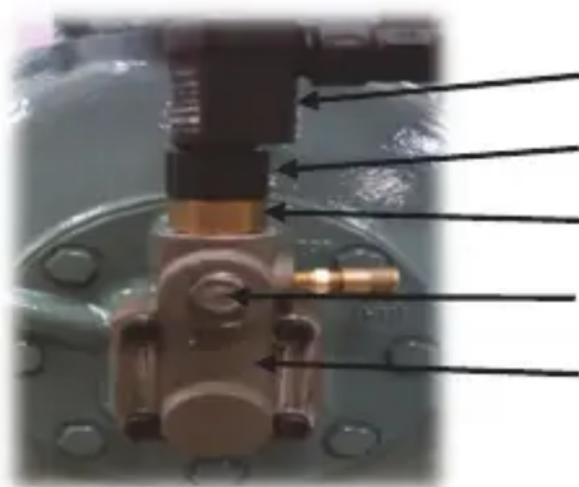
natural_image
Close-up of a mechanical component with no visible text or symbolsOPSS Electronic Unit (Part# 06DA509570)
Coupling Connection Ring (secure by hand)
OPSS Sensor installed (Part# 06DA509571)
Oil Pump pressure port (optional monitoring)
Sensor Block
Fig. 16 — OPSS Complete Assembly
OPSS Function:
- The OPSS differential oil pressure switch consists of two parts: a sensor unit and an electronic unit. The electronic unit can easily be disconnected from the sensor without opening the oil/refrigeration circuit.
- The OPSS serves to monitor the oil differential pressure of the oil pumps in refrigeration compressors. For this, a screw-in sensor is mounted directly to the pump housing and measures both the compressor's suction and oil pump pressure simultaneously. The screw-in sensor is thereby connected, by the sensor block, to the suction and high pressure side of the oil pump. Thus supplementary pipe connections are not needed.
- The OPSS electrical unit is fastened by a coupling ring to the screw-in sensor and can be removed without opening the oil/refrigeration circuit (not in direct contact with the oil circuit). See Fig. 17.
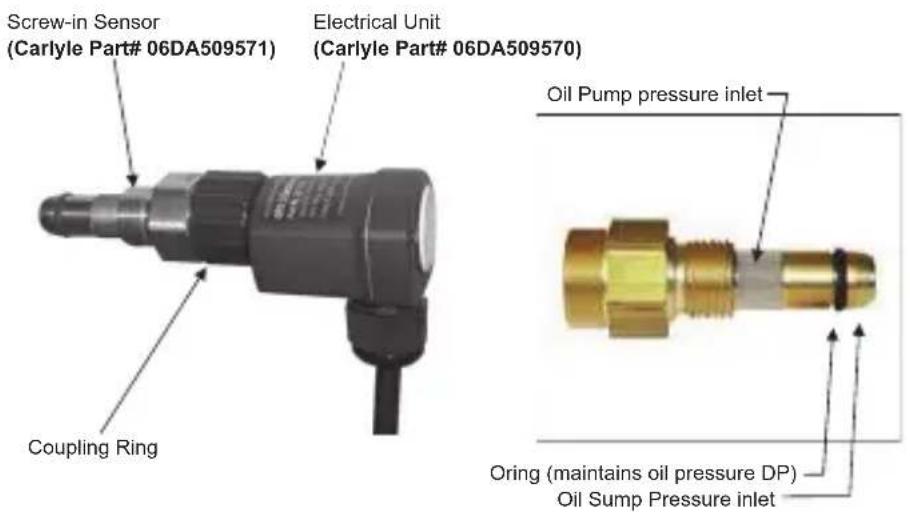
Fig. 17 — Oil Pressure Safety Switch
1. OPSS Operation:
- The OPSS is a dual power low oil DP switch 120/240Vac (Blue/Brown wires).
- Compressor Start: Oil pressure monitoring is activated once the supply voltage is applied to the operating recognition signal, which is applied to D1 (violet wire) via an auxiliary contactor or motor contactor (see wiring diagram). Following a compressor start, the OPSS allows for a 120 second oil pressure transition delay to allow the compressor to reach steady oil pressures. The differential pressure monitoring is activated after the expiration of the 120 second compressor starting transition time.
- A low differential oil pressure (9 psig) for a continuous 120 seconds will lead to a locked switch and trip the compressor off.
- Also, a time integrated low differential oil pressure (9 psig) that is fluctuating 60% of the time ≤slant to 9 psig over a 5 minute rolling window will lead to a locked switch and trip the compressor off.
- A manual reset of the relay can be carried out by the built-in push button, or by activating the operating recognition (D1) or by a 5 second power reset.
- The monitoring of internal errors is always active. Any faults that occur in any operational phase will lead to a locked switch off of the relay after 5 seconds and trip the compressor. The potential-free relay contact can be looped into a safety circuit without an auxiliary relay. An installation check monitors for the proper assembly. An LED status will indicate if the OPSS is faulty or not correctly installed (See LED Status Table).
- The built-in LED indicates the actual operating state of the compressor's oil pump pressure. Once the oil DP pre-
set value has been reached (13 psig), the LED light will be off and the OPSS output contacts remain in the closed position (Gray and Orange wires). If the differential oil pressure falls below the cut-out preset value (9 psig) for a continuous 120 seconds or a time integrated low delta P for 120 seconds, the OPSS output contacts will open and shut down the compressor and indicate the status per the LED indicator. (See LED Status Table.)
2. Oil Sensor Block Installation (06D/E/CC)
NOTE: 2-Cylinder 06D compressors (06DM808 and 06DR109) cannot support the Oil Sensor Block installation due to interference with the Service Valve position installed on the crankcase. Please contact Carlyle Engineering for options if you would like to apply the electronic OPSS to a 2-cylinder 06D compressor.
a. Remove cover plate bolts, cover plate and gasket from bearing head. (During reassembly be sure that spring and recess cup are in place and do not re-use factory installed gasket.)
b. Install the 1/4 in. NPT O-ring seal fitting into the high side oil pump pressure port on the compressor as shown in Fig. 18 (Torque to 20-25 ft/lbs):
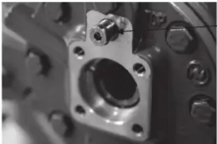
natural_image
Close-up of a mechanical component with a central hole and multiple bolts (no visible text or symbols)Install 1/4" NPT
O-ring fitting.
(P/N 06EA407204)
Fig. 18 — Cover Plate Removed
c. The sensor block gasket (P/N 06DA504473) is installed between the bearing head and sensor block with the bead side facing you. Lightly oil the gas- ket. Make sure the bearing head surface is clean and free from any debris. Refer to Fig. 19.
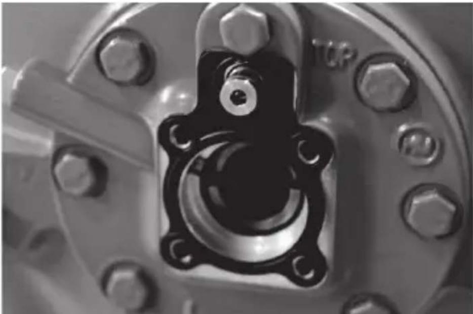
natural_image
Close-up of a mechanical component with bolts and a central bolt (no visible text or symbols)Fig. 19 — OPSS Block Gasket
d. Next, install the sensor block (P/N 06EA507202) over the gasket and the 1/4 in. NPT O-ring seal fitting as shown. Mount the sensor block to the bearing head using the four 5/16 in.-18 x 1-1/4 in. Allen head bolts provided in the kit (Torque to 15-20 ft/lbs). (Be sure spring and recess cup are in place). Refer to Fig. 20.
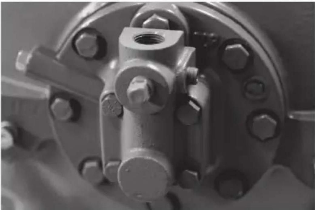
natural_image
Close-up of a mechanical valve component with bolts and flange (no visible text or symbols)Fig. 20 — OPSS Sensor Block Installed
- Install the OPSS sensor into the Sensor Block. Be sure the copper washer is in-place. Tighten the sensor's 1 in hex nut securely to the sensor block (torque 45-55 ft/lbs). See Fig. 21.
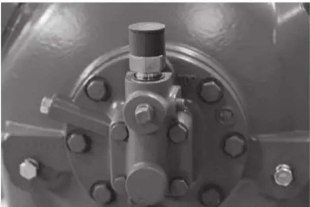
natural_image
Close-up of a metallic industrial valve component with bolts and a central shaft (no visible text or symbols)Fig. 21 — OPSS Sensor Installed
- Installation and Wiring for OPSS (06D/E/CC/M)
• Install the coupling ring end of the OPSS electrical unit to the sensor by hand and secure tightly.
- The electrical connections for the OPSS electrical unit need to be carried out according to the proposal in the wiring diagram (Fig. 22-24).
Technical Specifications
| Permitted Temperature -22°F to +194°F | |
| Differential Pressure | Cut-out 9 psig ±1 psigReset 13 psig ±1 psig |
| Operating Pressure 435 psig | |
| Electronic Unit (BN/BU) Dual Voltage Connection | AC 50/60 Hz 115-230V -15/+10% |
| Operating Recognition Connection(D1) Dual Voltage | AC 50/60 Hz 115-230V -15/+10% |
| Ambient Temperature Range -22°F to 158°F | |
| Delays: | |
| • Relay on after applying the supply voltage 3s ±1s | |
| • Relay on after previous locking 120s ±5s | |
| • Starting transition time D1 active 5s ±2s | |
| • Relay off (error) 5s ±2s | |
| • Relay off (diff. pressure missing) 120s ±5s (time integration) | |
| • Reset by interrupting the supply voltage About 5s | |
| • Reset by button About 1s | |
| • Reset by operating recognition (D1) About 1s | |
| Output Relay AC 240V 2.5A C300 | |
| Protection Class Acc. to EN60529 IP54 in built-in status | |
Wiring Diagrams
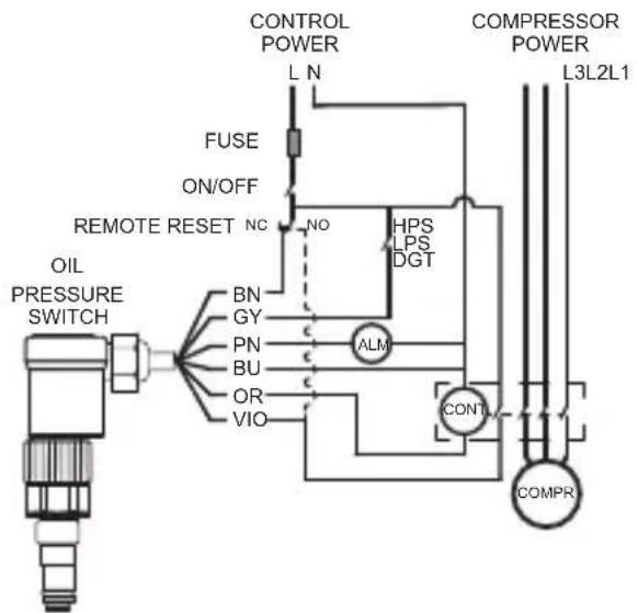
LEGEND
| BN (BROWN) | Line Power To OPPS |
| BU (BLUE) | Common Neutral |
| GY (GRAY) | Compressor Faults Input |
| VIO (VIOLET) | Compressor Run Status Input |
| OR (ORANGE) | Compressor Run Output |
| PN (PINK) | Compressor Alarm Output |
| ALM | Alarm Indicator |
| COMPR | Compressor Motor |
| CONT | Compressor Contactor |
| HPS, LPS, DGT | Compressor Safeties(Daisy chained high and low pressureswitches, discharge gas thermostat, etc.) |
| NC, NO | Normally Closed/Open |
Fig. 22 — Wiring Diagram OPSS
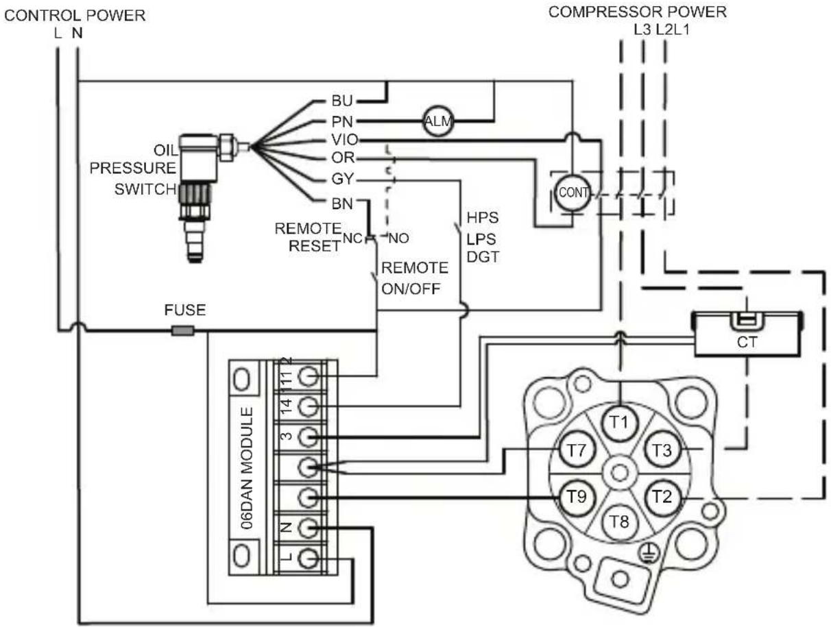
LEGEND
BN (BROWN) Line Power To OPSS
BU (BLUE)
Common
Neutral
GY (GRAY)
Compressor
Fault
Inputs
VIO (VIOLET) Compressor Run Status Input
OR (ORANGE)
Compressor
Run Output
PN (PINK)
Compressor
Alarm
Output
ALM
Alarm
Indicator
CONT
Compressor Contactor
HPS, LPS, DGT
Compressor Safeties
(Daisy chained high & low pressure switches, discharge gas thermostat, etc.)
NC, NO
Normally Closed/Open
Fig. 23 — Wiring Diagram OPSS-06D with Electronic Overloads and 1 CT
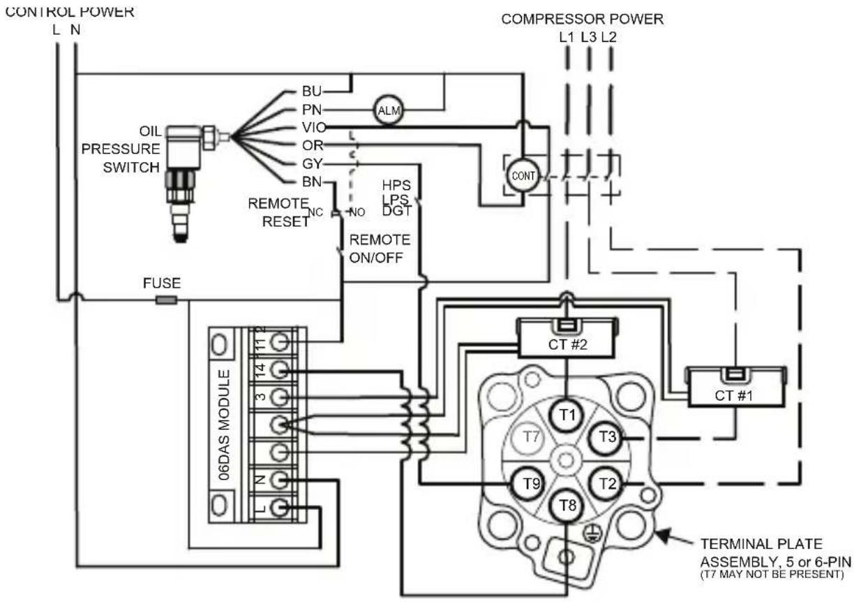
LEGEND
BN (BROWN) Line Power To OPSS
BU (BLUE) Common Neutral
GY (GRAY) Compressor Fault Inputs
VIO (VIOLET) Compressor Run Status Input
OR (ORANGE) Compressor Run Output
PN (PINK) Compressor Alarm Output
ALM Alarm Indicator
CONT Compressor Contactor
HPS, LPS, DGT Compressor Safeties
(Daisy chained high & low pressure switches, discharge gas thermostat, etc.)
NC, NO Normally Closed/Open
Fig. 24 — Wiring Diagram OPSS-06D with Electronic Overloads and 2 CT
The OPSS can be reset in three different ways:
- Disconnect the module from the power supply for 5 seconds.
- Push the reset button.
Once the module is reset, the compressor is allowed to re-start again after a 120 second time delay.
LED Status Table and Flash Codes
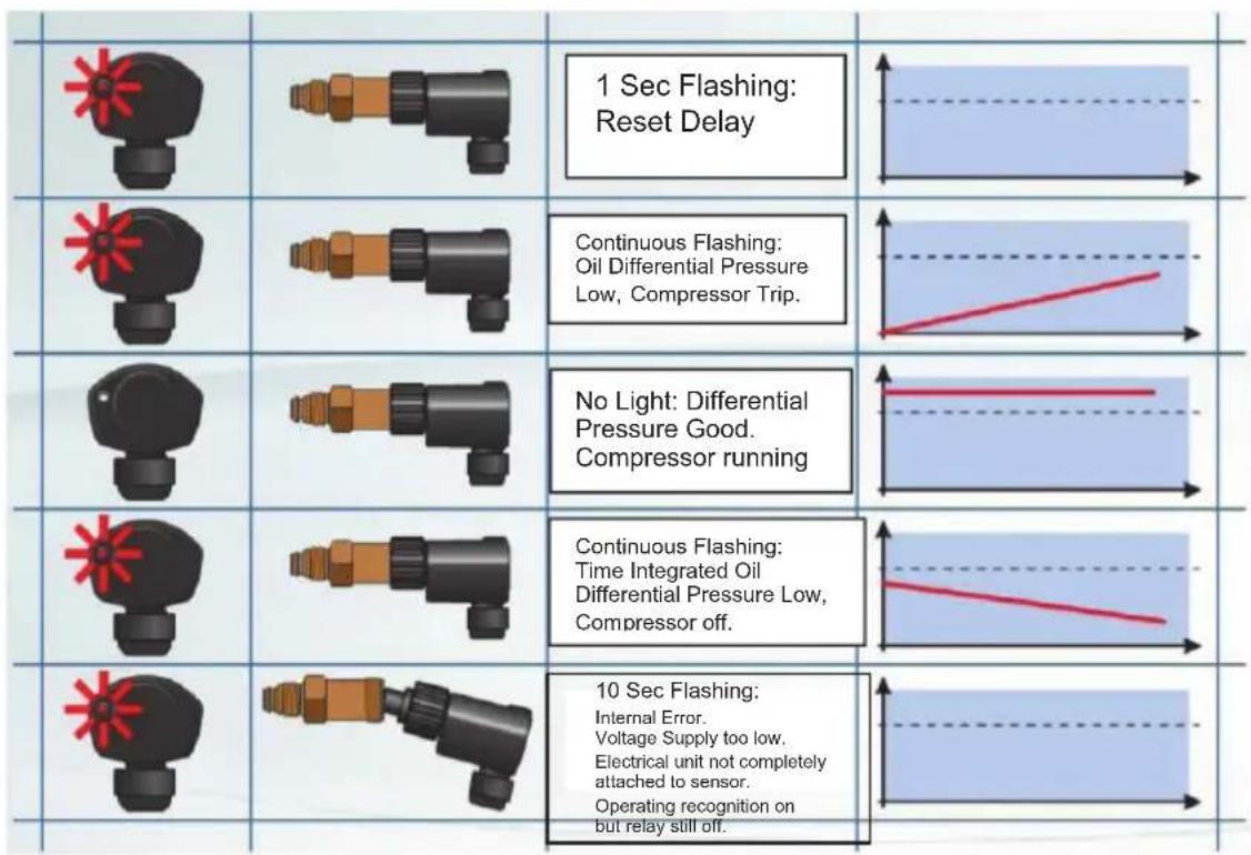
OPSS Removal
Carlyle recommends using OPSS to prevent compressor from loss of lubrication, but in some situations, if there is a need to remove the existing OPSS from the compressor's bearing head, it can be done by swapping the OPSS with the old style bearing head.
Kit number 6ADB001369 is needed to remove the OPSS and install the old style bearing head.
This kit will have all the necessary parts to retrofit the compressor with the old style bearing head.
3.10 — 06CC, E Discharge Gas Cylinder Head Temperature Sensor and 06E Pressure Relief Valve
All OEM Carlyle 06EA, EM, ER compressors are equipped with a discharge gas temperature sensor. The sensor is installed in the center head on all six-cylinder models. The four-cylinder 06E compressors have the sensor in the left side head as viewed from the oil pump end. All 06CC compressors have the sensor located in the high stage head.
When the discharge gas temperature in the cylinder head exceeds the sensor trip setting (see below), the sensor will open the control circuit and shut off the compressor. The head sensor must be wired into the control circuit by the OEM and is pilot duty only at 240V = 0.52A, at 115V = 1.04A. The sensors are threaded into the head without a well. Therefore, when changing a sensor, the compressor must first be isolated and evacuated.
CYLINDER HEAD TEMPERATURE SPECIFICATIONS
| Refrigeration from 1982 to mid-1998 for 06ER, EM, EY and EZ | All 06E and 06CC Compres-sors | |
| Part Number | HN68GA295 | HN68GA242 |
| Opens | 325°±8°F (163°±4°C) | 295°±5°F (146°±3°C) |
| Closes | 250°±12°F (121°±7°C) | 235°F minimum (113°C) |
| Wire Color | Silver Grey | Black |
| Thread | 1/2-in. NPT | 1/2-in. NPT |
NOTE: 325°F sensor is no longer available, for service replacement use HN68GA242.
NOTES:
- Since 1993 all Carrier 06 series air conditioning compressors have been made without a sensor. All Carlyle OEM 06 series compressors are equipped with a sensor.
- Starting in mid-1998 all Carlyle OEM compressors, including 06EA, EM, ER and all 06CC models, are built using the HN68GA242 sensor. The change to a single sensor model is due to the increased use of HFC refrigerants, which operate at lower temperatures.
Pressure Relief Valve
All 06E compressors are equipped with factory-installed safety relief valves that are set to relieve from the discharge to the suction side of the compressor at a pressure differential of 400 psi (27 bar). On the 4-cylinder 06E compressor, the relief valve is located below the discharge service valve in the compressor crankcase. On the 6-cylinder 06E compressors, it is located in the center bank (below the valve plate) of the crankcase. The relief valve is sealed with a metal gasket:
Part Number Description
EB51FN272 - 400 psi Relief Valve (differential pressure)
6G65-1251 - Relief Valve, Gasket
An 11/16 in. drag link socket can be useful for removing or installing the relief valve.
3.11 — 06D, E Cylinder Head Cooling Fans, and Liquid Injection
Cylinder head cooling fans are required in any application where the discharge gas temperature exceeds 250^ F ( 121.1^ C). Applications where the compressor is located in an airstream with a consistent velocity of 8 to 10 fps ( 3 m/s) do not require cylinder head fans.
Liquid refrigerant injection may be needed in some applications to keep discharge temperatures under the required limit in some high pressure ratio low temperature operating conditions. Liquid injection will reduce compressor capacity and can lead to increased risks of wear in the cylinders and running gear of the compressor. System controls towards lower suction gas superheats and lower operating pressure ratios are preferred in controlling discharge gas temperatures. Consult Application Engineering prior to installing liquid refrigerant injection on the Carlyle 06D or 06E compressors.
| CYLINDER HEAD COOLING FAN REPLACEMENT PARTS | ||
| DESCRIPTION 06D, 06CC (16 to 37 cfm) 06E, 06CC (50 to 99 cfm) | ||
| Head cooling fan assembly - 208/230V | 06DA680070 06DA680072 | |
| Head cooling fan assembly - 460V | 06DA680071 06DA680073 | |
| Head cooling fan assembly, less mounting - 208/230V | 06DA680074 06DA680074 | |
| Head cooling fan assembly, less mounting - 460V | 06DA680075 06DA680075 | |
| Mounting kit 06DA680076 06DA680077 | ||
| Replacement motor - 208/230V | 06DA680079 06DA680079 | |
| Replacement motor - 460V 06DA680078 06DA680078 | ||
| Replacement fan blade 06DA680080 06DA680080 | ||
| Mounting stud nuts 3/8 - 16 1/2 - 13 | ||
3.12 — Capacity Control Accessory Packages (Suction Cut-Off Unloading Type)
The following suction cut-off capacity control packages are available to field convert those 06D, 06E compressors without unloading. With the exception of the 06D 2-cylinder models, these packages can be added to any new, replacement, or existing 06D or 06E compressors. See Fig. 25.
NOTE: Before adding a suction cut-off control package to a compressor currently without unloading, consider all line piping sizes and design to ensure proper oil return to compressor with reduced (unloaded) refrigerant flow rates.
CAPACITY CONTROL PACKAGES
| CAPACITY CONTROL PACKAGES | ||||
| COMPRESSOR TYPE COLOR | PACKAGE NUMBER | BARE UNLOADER VALVE | ||
| 06D | Electric* | Green 06 | DA660177 | 06DA660175 |
| Gray 06 | DA660180 | |||
| Pressure† | Green 06 | DA660090 | 06DA660176 | |
| Gray 06 | DA660181 | |||
| 06E | Electric* | Green 06 | EA660171 | 06DA660175 |
| Gray 06 | EA660173 | |||
| Pressure† | Green 06 | EA660139 | 06DA660176 | |
| Gray 06 | EA660174 | |||
* Coil NOT included, order separately (see Section "3.13 — Capacity Control Coil Packages (06D, E)" on page 90).
† Special Allen head wrench to change valve is part number 06EA680036.
NOTES:
- Each package unloads 2 cylinders (1-step) and includes (1) cylinder head assembly with applicable unloader valve (electric or pressure) and necessary gaskets.
- When adding the suction cut-off unloading feature to any compressor, it is not required to change the valve plate.
- To avoid interfering with hi-lo pressure connections or cylinder head sensor, install the unloader cylinder head as follows (viewed from oil pump end of compressor):
06D 4-cyl - left hand cylinder deck 06E 4-cyl - right hand cylinder deck 06D, 06E 6-cyl - either cylinder deck (both when applicable)
-
Unloader valve gasket part number 06EA501253.
-
Unloader is not available for 06CC compressors.
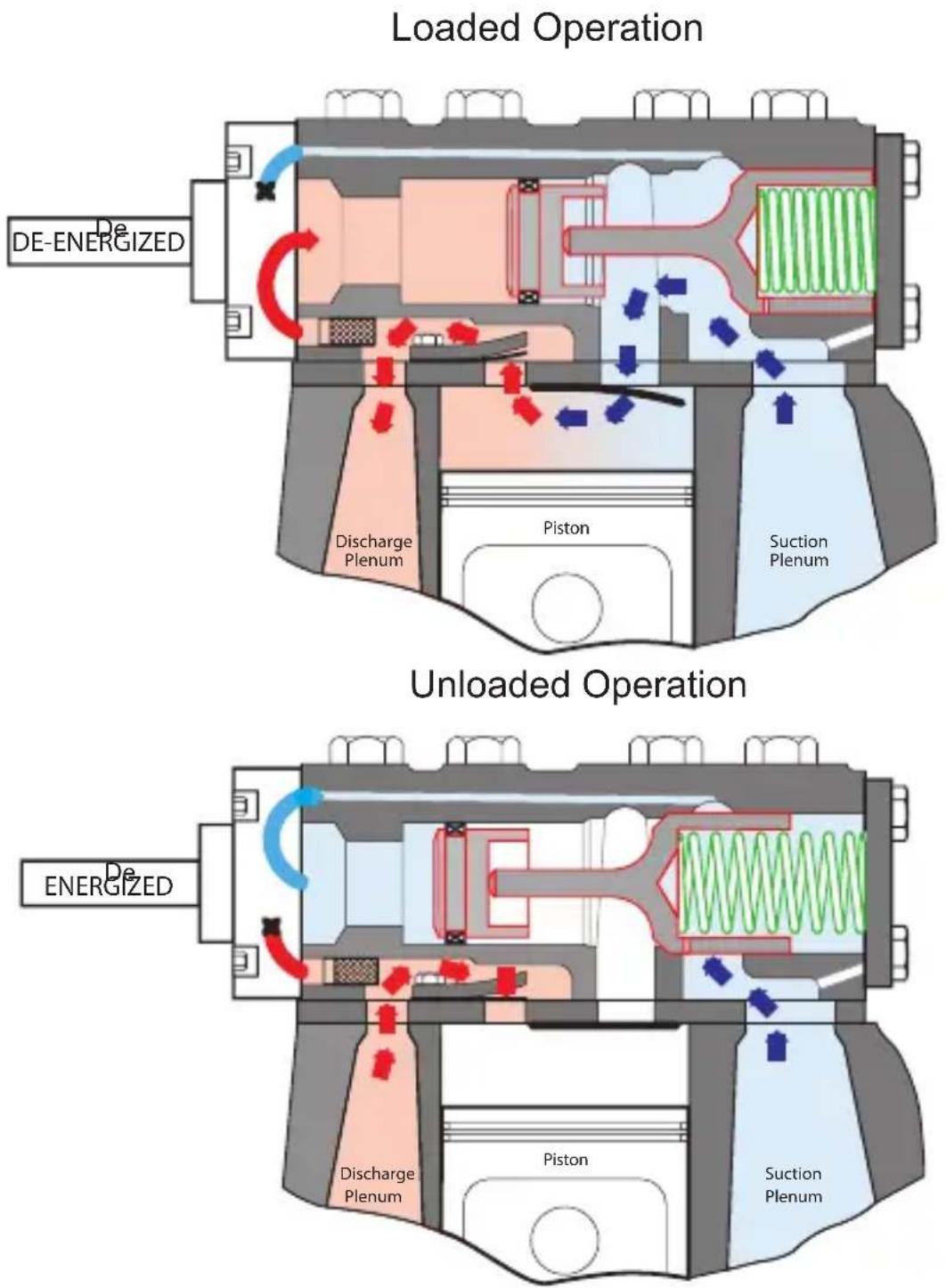
Fig. 25 — Loaded and Unloaded Operation
3.13 — Capacity Control Coil Packages (06D, E)
| COIL PACKAGE PART NUMBER VOLTAGE (V-PH-Hz) | |
| EF19ZZ001 24-1-50/60 | |
| EF19ZZ002 120-1-50/60 | |
| EF19ZZ003 208/240-1-50/60 | |
3.14 — Crankcase Heater Data
Crankcase heaters help reduce refrigerant migration to the compressor during shut-down. Crankcase heaters are designed to raise the temperature in the compressor oil compartment approximately 15 to 25°F (8 to 14°C). Carlyle recommends crankcase heaters be wired so the heater is energized only when the compressor shuts off. Crankcase heaters should be “ON” initially for 24 hours before starting the compressor. All HFC/POE applications require a crankcase heater.
STRAP-ON HEATERS:
Mounted externally to the underside of the stamp steel bottom plate. Install axially using (2) bottom plate bolts plus brackets and screws in package. Used on 06D() 808, 109, 013, 313, and 316 compressors. All strap-on heaters are 45 watts.
INSERTION HEATERS:
Insert into cast well (hole) in cast iron bottom plate. Circular clip with barbs secures heater. Used on 06D() 718, 818, and 820 4-cylinder compressors, all 6-cylinder 06D compressors, all 06E and all 06CC compressors. Insertion heaters are available in 125 and 180 watt sizes.
CRANKCASE HEATER PACKAGES
| CRANKCASE HEATER PACKAGE | TYPE | HEATER NUMBER | VOLTAGE | WATTS | CONDUIT LENGTH in. (cm) | WIRE LENGTH in. (cm) |
| RC6800551 S | Strap-on SH | S80300 115 45 | — 10 (25) | |||
| 06EA660165 | Insertion | HT36DM132 | 115 | 180 | 19 (48) | 24 (61) |
| 06EA660167 | Insertion | HT36DM134 | 115 | 180 | 52 (132) | 73 (185) |
| 06EA660166 | Insertion HT | 36DM432 230 | 180 19 (48) | 24 (61) | ||
| 06EA660168 | Insertion | HT36DM434 | 230 | 180 | 52 (132) | 73 (185) |
| 06DA660076 | Insertion | HT36DL480 | 480 | 125 | — | 24 (61) |
3.15 — Compressor Mounting Data
Mounting packages are available to mount individual compressors. Package contains mounting springs, threaded studs, snubbers, spring cups, nuts, and washers for (1) compressor.
| MOUNTING PACKAGE NUMBER USE WITH BODY STYLE | |
| 06DA660058 | 06D 2-cylinder |
| 06DA660056 | 06D 4-cylinder |
| 06DA660057 | 06D, 06CC (16 to 41cfm) 6-cylinder |
| 06EA660089 | 06E 4 and 6-cylinder and 06CC (50 to 99cfm) |
3.16 — Compressor Service Valves and Gaskets (06D, E, CC)
| VALVE PACKAGE NO.* | ODS (in.) DESCRIPTION | FIBER GASKET PACKAGE** | METAL GASKET PACKAGE | |
| 06DA660060 5/8 brass | 2-bolt 1-5/8 in. spacing | 6D23-1421 06 | DA504143 | |
| 06DA660061 7/8 brass | ||||
| 06DA660062 7/8 brass | 2-bolt 1-3/4 in. spacing | 6D40-1131 06 | DA504163 | |
| 06DA660063 1-1/8 brass | ||||
| 06DA660064 1-1/8 brass | 4-bolt 2-1/2 in. spacing | 6D68-1131 06 | DA50415306DA660065 1-3/8 | |
| 06EA660090 1-5/8 brass | ||||
| 06EA660164 2-1/8 brass | Circular, No Holes, for 4-bolt 3-1/16 in. spacing | 6G65-1061 N/A | ||
* Packages consist of (1) service shut-off valve and required fiber gasket and mounting bolts.
**Package contains 12 gaskets.
3.17 — Oil Drain Plug Adapter
All new compressors, except for 06D() 808, 109, 013, 313, and 316 models, are built with a 7/16-20 SAE fitting and
O-ring as the oil drain plug. Carlyle offers an oil drain adapter, P/N DE14CA126, which replaces the SAE plug. This adapter allows the installation of a 1/4 in. NPT angle valve as a drain fitting.
3.18 — Sight Glass Adapters for Oil Equalization
| ADAPTER PACKAGE P/N COMP | RESSOR USAGE |
| 06DA900072 | For 06D and 06CC (16 to 37 cfm) |
| 06EA660127 | For 06E and 06CC (50 to 99 cfm) |
3.19— Replacement Sight Glass/Installation Tool
| SIGHT GLASS PACKAGE/INSTALLATION TOOL | COMPRESSOR USAGE |
| 5F20-152 Sight Glass (S.G.)*KM39BN010 (S.G. without O-ring)KK71GW015 (O-ring for S.G.)T133300B-1 (Installation Tool) | All 06Ds and 06CC (16 to 37 cfm)All 06Es and 06CC (50 to 99 cfm)All 06Es and 06CC (50 to 99 cfm)All 06Ds and 06CC (16 to 37 cfm) |
* 5F20-152 sight glass assembly includes 5F20-1631 gasket.
3.20 — Replacement Motor End Mounting Foot
| MOTOR END FOOT P/N COMPRESSOR USAGE | MOUNTING HOLE WIDTH (in.) | |
| 6D40-1042 | All 2 cylinder 06DAll 4 cylinder 13 and 16 cfm 06DAll 6 cylinder 06DA A/C duty models | 8.875 |
| 6D48-2063 All 4 cylinder 18 ans 20 cfm 06D 8.25 | ||
| 06EA500052 | All 4 cylinder 06DR and DM and 06CC (16 to 37 cfm “D” Body)All 06EA A/C duty models | 8.875 and 11.375 |
| 06EA501172 | 06CC (50 to 99 cfm “E” Body) and All 06ER/EM Refrig. duty models | 8.875 and 11.375 |
3.21 — Gaskets - Cylinder Head and Valve Plate
| GASKET TYPE PART NUMBER | |
| 06D COMPRESSORS | |
| 1:Cylinder head gasketsa. Side bank, no unloadingb. Side bank, with unloading (suction cut-off design)c. Side bank, with unloading (hot gas bypass design)d. Center bank2:Valve plate gasketsa. Standard 2 in. diameter cylinder boreb. Old design 1-13/16 in. diameter cylinder borec. Blank-off (special) used only on old standard 16 cfm models with suction valve at P.E. and using H.E. valve plates | 05GA50221305GA50222305GA50218305GA50217305DA5001536D40-107306DA502923 |
| 06E COMPRESSORS | |
| 1:Cylinder head gasketsa. Side bank, no unloadingb. Side bank, with unloading (suction cut-off design)c. Side bank, with unloading (hot gas bypass design)d. Center bank | 06EA50330406EA50333406EA50331406EA503314 |
| 2:Valve plate gasketsa. H.E., low temperature (ER, EY) 0.028"/0.036"b. H.E., medium temperature (EM, EZ) 0.067"/0.072"c. H.E., high temperature (EA, ET) 0.067"/0.072"d. Old standard, low temperature (ER, EY) 0.035"/0.041"e. Old standard, medium temperature (EM, EZ) 0.035"/0.041"f. Old standard, high temperature (EA, EX) 0.067"/0.072" | Package #06ER660012 contains:(1) 06EA501853 gasket/(2) suction valves06EA504884 (fiber) or06EA506414 (metal)06EA50641806ER66001206ER66001206EA504884 |
| 06CC COMPRESSORS | |
| 1:16 to 37 cfma. Cylinder headb. Valve platec. Suction manifoldd. Interstage manifolde. Liquid injectionf. Interstage tube | 05GA50221305DA5001536D40-1131*6D40-1131*6D23-1421*6D23-1421* |
| 2:50 to 99 cfma. Cylinder headb. Valve platec. Suction manifoldd. Interstage manifolde. Vapor injection (Subcooler)f. Interstage tube | 06EA50333406EA5064146D68-1131*6D68-1131*6D23-1421*6D68-1131* |
* Service package contains 12 gaskets.
NOTE: "H.E." and "Old Standard" are designations based on date of manufacture; see Section 3.4 page 66 for details.
3.22 — Miscellaneous
Terminal Plate Gasket
| COMPRESSOR USAGE GASKET | |
| 06D, 06CC (16 to 37 cfm) | 6D40-1061 |
| 06E, 06CC (50 to 99 cfm) | 6G45-1082 |
OPSS Sensor Block Gasket
| COMPRESSOR USAGE GASKET | |
| 06D, 06E, 06CC 06DA504473 |
Electrical Terminal Barrel Nut Tool (Socket tool used for installation for terminal nuts)
| COMPRESSOR USAGE GASKET | |
| All 06D, 06CC (16 to 37 cfm) P920-0009 |
3.23 — Valve Plate Packages, Service Replacement
| COMPRESSOR USAGE VALVE PLATE PACKAGE | |
| 06D, 06CC (17 to 41 cfm) Compressors | |
| a. 06DR (if using 06DR013 or 06DR316 models see note 1) | 06DA660151 |
| b. 06DM, DA (if using 06DM313, or 06DM316 models see note 1) | 06DA660152 |
| c. 06CC (16 to 37 cfm) low stage valve package | 06CY660002 |
| d. 06CC (16 to 37 cfm) high stage valve package | 06DA660152 |
| 06E, 06CC (50 to 99 cfm) Compressors | |
| a. 06ER | 06EA660143 |
| b. 06EM, EA | 06EA660137 |
| c. 06CC (50 to 99 cfm) low stage valve* | 06EA660159 |
| d. 06CC (50 to 99 cfm) high stage valve | 06EA660137 |
* Includes relief valve for both low stage banks.
NOTES:
1. All high efficiency (units with a "3" in the 11th digit of the model number) 06DR013 and 06DM313, 06DR316, and 06DM316 models have a 2 in. diameter cylinder bore and use the above valve plate kits. Older 13 and 16 cfm (prior to 1985) models have a 1-13/16 in. diameter bore and cannot use these valve plate kits. Kits for these models are no longer available. Suction reed valve (part no. 6D45-1072) and discharge reed valve (part no. 6D75-1062) can be used for valve plate field repair.
2. Carlyle recommends that all HGBP unloading be converted to SCO unloading. Compressors that have two stages of unloading should have both stages changed at the same time. Do not intermix SCO and HGBP unloading on the same compressor.
Hot gas bypass unloading valve plate kits are:
06D....06DA660131
06E....06EA660105
The Carlyle recommended suction cut-off unloading does not require a special valve plate. Suction cutoff unloading uses the standard high efficiency valve plate kit, which includes the needed gasket.
-
Service valve plate kits include: (1) valve plate assembly, (2) suction reed valves, (3) cylinder head gaskets (side, center and suction gas unloading), (1) valve plate gasket; and for 06D compressors there are (2) suction valve position springs.
-
All 06DM, 06DA, and 06CC (16 to 37 cfm) compressors have flat top pistons. All 06DR and 06ER compressors have one step contoured pistons. All 06EM, 06EA, and 06CC (50 to 99 cfm) compressors have two-step contoured pistons.
3.24 — Muffler Recommendations
Mufflers can reduce discharge gas pulsation and effectively eliminate vibration problems downstream. They should be placed as close to the compressor as possible to maximize efficiency and minimize vibration. Mufflers are recommended in the following applications:
- All 06E 66 and 99 cfm compressor models.
- Any 06E compressors with capacity control.
- All 06D 37 and 41 cfm compressor models.
- Any 06D 6-cylinder compressors with capacity control.
| MUFFLER PART NO. | ALTERNATE MUFFLER PART NO. | WEIGHT LB (KG) | INLET/ OUTLET (in.) | COMPRESSOR SIZED BY cfm |
| 06DA605594 1 | 762 5 (2.3) 5/8 O | DM 08, 09, 13, 16 | ||
| 06DA605604 1 | 758 5 (2.3) 7/8 O | DF 18, 20, 24 | ||
| 06DA605614 1 | 792 5 (2.3) 1-1/8 | ODF 28, 37, 41 | ||
| 06EA500302 1 | 771 10 (4.5) 1-3/8 | ODF 50 | ||
| LM10HH100 1 | 771 6 (2.7) 1-3/8 | ODF 65, 75 | and 06E()399 | |
| 06EA500712 1 | 772 7 (3.2) 1-5/8 | ODF | 06E()499, 599, and 06CC899 |
Mufflers can be mounted horizontally or vertically.
3.25 — Electrical Accessories
TERMINAL BOX PACKAGE NUMBERS - This consists of terminal box, cover, and necessary mounting components.
| TERMINAL BOX PACKAGE NUMBER | T-BOX NUMBER | TYPE | COLOR | COMPRESSOR USAGE AND SIZE | DIMENSIONS ft (cm) |
| 06DA660150 | 06DA660078 | Large, Folded | Green | All 06D 2,4,6-cylinder and 06CC 16 to 37 cfm | (6" x 8") (15.2 x 20.3 cm) |
| 06DA660075 | 06DA407734 | Small, Folded | Green | All 06D 4,6 cylinder | (6" x 5") (15.2 x 12.7 cm) |
| 06EA660095 | 06EA504684 | Drawn Steel | Green | All 06E 4,6-cylinder and 06CC 50 to 99 cfm | (6" x 8") (15.2 x 20.3 cm) |
| 06DA660088 | 06DA407764 | Large, Folded | Gray | All 06D 2,4,6-cylinder and 06CC 16 to 37 cfm | (6" x 8") (15.2 x 20.3 cm) |
| 06EA660094 | 06EA406294 | Drawn Steel | Gray | All 06E 4,6-cylinder and 06CC 50 to 99 cfm | (7.8" x 7.8") (19.8 x 19.8 cm) |
NOTE: Information in shaded area is no longer available in standard factory production.
TERMINAL LUG PACKAGE - The 06DA660095 package consists of six, screw-on terminal lugs with set screws. The HY85TB004 and HY85TB008 packages consist of one terminal lug (six required per compressor).
| TERMINAL LUG PACKAGE NUMBER | COMPRESSOR USAGE |
| 06DA660095HY85TB008HY85TB004 | All 06D and 06CC 16 to 41 cfm.All 06E and 06CC 50 to 99 cfm #4 to #8 Wire Size.All 06E and 06CC 50 to 99 cfm #1 to #4 Wire Size. |
TERMINAL PLATE JUMPER PACKAGE FOR 06E, 06CC 50 TO 99 cfm - This package consists of jumper bars, terminal nuts and instructions to interconnect terminal studs for proper motor starting (PW or XL) and voltage.
| JUMPER PACKAGE NUMBER USAGE | |
| 06EA660141 208/230/460 (triple and distinct voltage) |
NOTE: With 06E multi-volt (208/230/460) compressors, the 460-volt motor can be connected only for across-the-line start. A compressor with a distinct 460-volt motor (or designated P/W) must be used for part-winding start.
3.26 — Baffle Plate Recommendations
Baffle plates can be used to reduce compressor discharge gas pulsations. Recommended baffle plate assemblies are shown below. These plates are designed to create a 6 to 10 psi (0.4 to 0.7 bars) pressure drop in the discharge gas. Use only the baffle plate recommended for the application.
These baffle plates, sandwiched between two gaskets, are installed between the compressor discharge service valve and the compressor crankcase or cylinder head. For further details, see 99TA516198B located on Carlyle's website.
NEW CONSOLIDATED BAFFLE PLATE KITS
Carlyle has revised the baffle plate kit offerings to cover all of the current applications for the 06D, 06E and 06CC compressors. There will be one kit for each of the three different flange connections used (1-5/8 in., 1-3/4 in. and 2-1/2 in. square pattern). Plates will come predrilled for the smallest application used in that configuration. For the larger applications, the holes may need to be enlarged at the job site prior to installation. Please verify the hole size required for your application. Some of the kit numbers now cover smaller applications and will require that the holes to be enlarged when applied in applications that previously did not require modification.
In addition to the standardization and consolidation of the kits, installation instructions are now included along with the fittings required to measure the pressure drop across the plates. An installation tag is also provided for future identification and servicing reference.
Baffle plates have been applied in refrigeration applications to help reduce gas pulsation in discharge line assem-
blies, this helps to minimize the potential for line vibration. The baffle plates are typically installed between the discharge service valve and the compressor body or center cylinder head.
-
Carlyle does not recommend Baffle Plates for new design applications. In a newly engineered system, the piping can be designed to minimize line vibration such that baffle plates are not required.
-
Baffle plates are typically sized for the refrigerant applications at full design load conditions. Once installed, verifying the actual pressure drop is recommended. Modifying the Baffle Plate (enlarging some of the orifices) may be necessary if the pressure drop is excessive.
BAFFLE PLATE ADVANTAGES:
- Easily applied on a compressor or system. Especially easy on retrofits of existing system that exhibit piping vibration concerns.
- Effectively reduces pulsation at certain range of operating conditions. Carlyle recommends 6 to 10 psi pressure drop to obtain effective discharge pulsation reductions. This requires different baffle plate sizes for different compressor displacements. A detailed list of our current recommendations is shown in chart on page 101 and 102.
- The most cost effective method of reducing gas pulsation.
101
BAFFLE PLATE RECOMMENDATIONS
| COMPRESSOR MODEL | Low Temperature Duty Medium | Temperature Duty High Temperature Duty | ||||
| Part Number | Orifice: (Qty.) Diameter | Part Number | Orifice: (Qty.) Diameter | Part Number | Orifice: (Qty.) Diameter | |
| 06DM808 — — 06DA660103 (3) 5/32" 06DA660103 (3) 5/32" | ||||||
| 06DR109 06DA660103 (3) 5/32" — — — | ||||||
| 06DR013 06DA660103 (3) 5/32" — — — | ||||||
| 06DM313 — — 06DA660103 (3) 5/32" 06DA660103 (3) 5/32" | ||||||
| 06DR316 06DA660103 (3) 3/16"† — — — | ||||||
| 06DM316 — — 06DA660103 (3) 3/16"† 06DA660103 (3) 3/16"† | ||||||
| 06DR718 06DA660103 (3) 3/16"† — — — | ||||||
| 06DA818 — — 06DA660103 (3) 3/16"† 06DA660103 (3) 3/16"† | ||||||
| 06DR820 | 06DA660103 | (3) 3/16"† | 06DA660103 | (3) 3/16"† | 06DA660103 | (3) 3/16"† |
| 06DR725 | 06DA660104 | (3) 7/32" | 06DA660104 | (3) 17/64"† | 06DA660104 | (3) 17/64"† |
| 06DA825 | — | — | 06DA660104 | (3) 17/64"† | 06DA660104 | (3) 17/64"† |
| 06DR228 | 06DA660104 | (3) 7/32" | 06DA660104 | (3) 17/64"† | 06DA660104 | (3) 17/64"† |
| 06DA328 | — | — | 06DA660104 | (3) 17/64"† | 06DA660104 | (3) 17/64"† |
| 06DR337 06DA660104 (3) 7/32" 06DA660104 (3) 17/64"† — — | ||||||
| 06DM337 | — | — | 06DA660104 | (3) 17/64"† | 06DA660104 | (3) 17/64"† |
*Can be any letter or number in the compressor model.
†Holes need to be enlarged to the diameter shown at the time of installation.
102
| BAFFLE PLATE RECOMMENDATIONS (cont) | ||||||
| COMPRESSOR MODEL | Low Temperature Duty Medium | Temperature Duty High Temperature Duty | ||||
| Part Number | Orifice: (Qty.) Diameter | Part Number | Orifice: (Qty.) Diameter | Part Number | Orifice: (Qty.) Diameter | |
| 06ER*50 06DA660104 (3) 17/64"† — — — — | ||||||
| 06EM*50 — — 06DA660104 (3) 17/64"† 06DA660104 (3) 7/16"† | ||||||
| 06EA*50 — — 06DA660104 (3) 17/64"† 06DA660104 (3) 7/16"† | ||||||
| 06ER*65 06EA660145 (4) 9/32" — — — — | ||||||
| 06EA*65 | 06EA660145 | (4) 9/32" 06EA660145 (4) 1/2"† | ||||
| 06ER*75 06EA660145 (4) 9/32" — — — — | ||||||
| 06EM*75 — | — | 06EA660145 | (4) 9/32" | 06EA660145 | (4) 1/2"† | |
| 06EA*75 — | — | 06EA660145 | (4) 9/32" | 06EA660145 | (4) 1/2"† | |
| 06ER*99 06EA660145 (4) 9/32" — — — — | ||||||
| 06EM*99 — — 06EA660145 (4) 15/32"† 06EA660145 (4) 1/2"† | ||||||
| 06EA*99 — — 06EA660145 (4) 15/32"† 06EA660145 (4) 1/2"† | ||||||
| 06CC*17 06DA660104 (3) 17/64"† — — — — | ||||||
| 06CC*25 06DA660104 (3) 17/64"† — — — — | ||||||
| 06CC*28 06DA660104 (3) 17/64"† — — — — | ||||||
| 06CC*37 06DA660104 (3) 17/64"† — — — — | ||||||
| 06CC*50 06EA660145 (4) 9/32" — — — — | ||||||
| 06CC*65 06EA660145 (4) 9/32" — — — — | ||||||
| 06CC*75 06EA660145 (4) 9/32" — — — — | ||||||
| 06CC*99 06EA660145 (4) 9/32" — — — — | ||||||
*Can be any letter or number in the compressor model.
†Holes need to be enlarged to the diameter shown at the time of installation.
BAFFLE PLATE LIMITATIONS
-
Baffle plates are effective within certain operating envelopes. Changes in refrigerant can dramatically change refrigerant mass flow and pressure drop. Carlyle has published application recommendations for low, medium and high temperature duty applications. These should be followed to avoid excessive pressure drops. See chart on page 101 and 102.
-
Baffle plates are typically sized for the refrigerant and application at full design load conditions. When the compressor is unloaded using the step unloading method and operated at part load, the mass flow through the compressor is reduced by 1/3, 1/2, or 2/3. This reduction in mass flow reduces the pressure drop through the baffle plate and its effectiveness in reducing discharge gas pulsation. Mufflers and good piping practices should be considered on compressors with unloading capability.
-
Conversely, system changes that increase the mass flow of the compressor will increase the pressure drop through the baffle plates. Dramatically increasing the suction pressure (in many refrigeration systems, this occurs at the termination of defrost cycles) will result in a large increase of mass flow. This results in very high pressure drops and values as high as 40-50 psi have been reported. This occurrence is not a problem unless the compressor motor protection limit is reached. In this case, the maximum suction pressure that the compressor is allowed to operate at must be limited.
-
Another operating condition that significantly increases the mass flow is a dramatic decrease in the compressor's discharge pressure. This can occur on systems with floating head pressures. In the wintertime, the discharge pres-
sure may be half or less than what it would be during hot periods in the summer. With reciprocating compressors, this dramatic reduction in discharge pressure increases the volumetric (or pumping) efficiency of the compressor while lowering the discharge temperature of the refrigerant. The combination can result in the same large pressure drops noted in Step 3 above. If this occurs, the minimum allowable discharge pressure may have to be limited, or a baffle plate with more holes should be used. This avoids the high pressure drops but compromises the reduction in pressure pulsation at summer time conditions.
- Finally, compressor start-up can also result in even higher discharge pressure drops across the baffle plate. At start-up, the combination of high suction pressures and low discharge pressures occur. This results in pressure drops of over 100 psi at start-up until the suction pressure drops to design conditions and the discharge pressure rises.
Application Note:
Baffle plates are typically sized for the refrigerant and application at full design load conditions. The recommendations defined in Chart A do not guarantee baffle plate pressure drop will not exceed 6-10 psi. Therefore it is necessary that all installed baffle plates be field qualified by verifying the actual pressure drop across the baffle plate at full load design saturated suction temperature (SST) conditions. If the baffle plate pressure drop is excessive, it will be necessary to modify the baffle plate by enlarging the orifice holes to achieve the recommended pressure drop between 6-10 psi.
3.27 — Interstage Pressure Tables (06CC Compressors Only)
All 06CC compressors are a 2-Stage design. Therefore, the pressure measurements are suction, interstage, and discharge. The following tables list the interstage pressures using R-22, R-407A, R404A, R507, and R448A/R449A refrigerants. Refer to section 3.27 — Interstage Pressure Tables (06CC Compressor Only on pages 106-110).
901
R-22 APPROXIMATE INTERSTAGE PRESSURE +/- 10 PSI (0.7 BAR) WITH SUBCOOLER
| SATURATED SUCTION TEMP | SUCTION PRESSURE | Saturated Condensing Temperature | |||||||||||||||||||
| F | C | F | C | F | C | F | C | F | C | ||||||||||||
| 60 | 15.6 | 70 | 21.1 | 80 | 26.7 | 90 | 32.2 | 100 | 37.8 | 110 | 43 | 3 | 120 | 48.9 | 130 | 54.4 | |||||
| Condensing Pressure | |||||||||||||||||||||
| PSIG | BAR | PSIG | BAR | PSIG | BAR | PSIG | BAR | PSIG | BAR | PSIG | BAR | PSIG | BAR | PSIG | BAR | PSIG | BAR | ||||
| F | C | PSIG | BAR | 101.6 | 8.0 | 121.4 | 9.4 | 143.6 | 10.9 | 168.4 | 12.6 | 195.9 | 14.5 | 226.4 | 16.6 | 259.9 | 18.9 | 296.9 | 21.5 | ||
| -60 | -51.1 | 11.9* | 0.6 | 17.4 | 2.2 | 20.0 | 2.4 | 22.7 | 2.6 | 25.5 | 2.8 | 28.4 | 3.0 | 31.5 | 3.2 | 34.6 | 3.4 | 37.8 | 3.6 | ||
| -55 | -48.3 | 9.2* | 0.7 | 19.7 | 2.4 | 22.5 | 2.6 | 25.5 | 2.8 | 28.5 | 3.0 | 31.6 | 3.2 | 34.9 | 3.4 | 38.2 | 3.6 | 41.6 | 3.9 | ||
| -50 | -45.6 | 6.1* | 0.8 | 22.2 | 2.5 | 25.2 | 2.8 | 28.3 | 3.0 | 31.6 | 3.2 | 34.9 | 3.4 | 38.4 | 3.7 | 42.0 | 3.9 | 45.7 | 4.2 | ||
| -45 | -42.8 | 2.7* | 0.9 | 24.8 | 2.7 | 28.0 | 2.9 | 31.3 | 3.2 | 34.8 | 3.4 | 38.4 | 3.7 | 42.1 | 3.9 | 45.9 | 4.2 | 49.9 | 4.5 | ||
| -40 | -40.0 | 0.6 | 1.1 | 27.4 | 2.9 | 30.9 | 3.1 | 34.5 | 3.4 | 38.2 | 3.6 | 42.0 | 3.9 | 46.0 | 4.2 | 50.0 | 4.5 | 54.3 | 4.8 | ||
| -35 | -37.2 | 2.6 | 1.2 | 30.2 | 3.1 | 33.9 | 3.4 | 37.7 | 3.6 | 41.6 | 3.9 | 45.7 | 4.2 | 49.9 | 4.5 | 54.3 | 4.8 | 58.8 | 5.1 | ||
| -30 | -34.4 | 4.9 | 1.4 | 33.1 | 3.3 | 37.0 | 3.6 | 41.0 | 3.8 | 45.2 | 4.1 | 49.6 | 4.4 | 54.1 | 4.7 | 58.7 | 5.1 | 63.5 | 5.4 | ||
| -25 | -31.7 | 7.4 | 1.5 | 36.1 | 3.5 | 40.2 | 3.8 | 44.5 | 4.1 | 49.0 | 4.4 | 53.6 | 4.7 | 58.4 | 5.0 | 63.3 | 5.4 | 68.4 | 5.7 | ||
| -20 | -28.9 | 10.2 | 1.7 | 39.1 | 3.7 | 43.5 | 4.0 | 48.1 | 4.3 | 52.8 | 4.7 | 57.7 | 5.0 | 62.8 | 5.3 | 68.0 | 5.7 | 73.4 | 6.1 | ||
| -15 | -26.1 | 13.2 | 1.9 | 42.3 | 3.9 | 47.0 | 4.3 | 51.8 | 4.6 | 56.8 | 4.9 | 62.0 | 5.3 | 67.4 | 5.7 | 72.9 | 6.0 | 78.6 | 6.4 | ||
| -10 | -23.3 | 16.5 | 2.2 | 45.6 | 4.2 | 50.5 | 4.5 | 55.6 | 4.8 | 60.9 | 5.2 | 66.4 | 5.6 | 72.1 | 6.0 | 77.9 | 6.4 | 83.9 | 6.8 | ||
* Indicates Vacuum - Inches of Hg.
NOTE: 1 BAR = 100 kPa or 1 ATM (Atmosphere) Pressure.
101
R-407A APPROXIMATE INTERSTAGE PRESSURE +/- 10 psi (0.7 BAR) WITH SUBCOOLER
| SATURATED SUCTION TEMP | SUCTION PRESSURE | Saturated Condensing Temperature | |||||||||||||||||
| F | C | F | C | F | C | F | C | F | C | F | C | F | C | F | |||||
| 60 15 | 6 70 2 | 1.1 80 2 | 6.7 90 3 | 2.2 100 | 37.8 | 10 43.3 | 120 48 | 9 130 | 54.4 | ||||||||||
| Condensing Pressure | |||||||||||||||||||
| PSIG | BAR | PSIG | BAR | PSIG | BAR | PSIG | BAR | PSIG | BAR | PSIG | BAR | PSIG | BAR | PSIG | BAR | ||||
| F | C | PSIG | BAR | 125.2 | 9.6 | 148.8 | 11.3 | 175.3 | 13.1 | 204.8 | 15.1 | 237.6 | 17.4 | 273.9 | 19.9 | 314.0 | 22.7 | 357.9 | 25.7 |
| -60 | -51.1 | 14.5* | 0.5 | 17.9 | 2.2 | 20.5 | 2.4 | 23.3 | 2.6 | 26.1 | 2.8 | 29.1 | 3.0 | 32.1 | 3.2 | 35.3 | 3.4 | 38.5 | 3.7 |
| -55 | -48.3 | 11.9* | 0.6 | 20.5 | 2.4 | 23.4 | 2.6 | 26.3 | 2.8 | 29.4 | 3.0 | 32.6 | 3.3 | 35.9 | 3.5 | 39.3 | 3.7 | 42.8 | 4.0 |
| -50 | -45.6 | 9.0* | 0.7 | 23.2 | 2.6 | 26.3 | 2.8 | 29.5 | 3.0 | 32.8 | 3.3 | 36.3 | 3.5 | 39.8 | 3.8 | 43.5 | 4.0 | 47.2 | 4.3 |
| -45 | -42.8 | 5.7* | 0.8 | 26.1 | 2.8 | 29.4 | 3.0 | 32.8 | 3.3 | 36.4 | 3.5 | 40.1 | 3.8 | 43.9 | 4.0 | 47.8 | 4.3 | 51.9 | 4.6 |
| -40 | -40.0 | 2.0* | 0.9 | 29.1 | 3.0 | 32.6 | 3.3 | 36.3 | 3.5 | 40.1 | 3.8 | 44.1 | 4.1 | 48.2 | 4.3 | 52.4 | 4.6 | 56.8 | 4.9 |
| -35 | -37.2 | 1.0 | 1.1 | 32.2 | 3.2 | 36.0 | 3.5 | 39.9 | 3.8 | 44.0 | 4.1 | 48.3 | 4.3 | 52.7 | 4.6 | 57.2 | 5.0 | 61.8 | 5.3 |
| -30 | -34.4 | 3.3 | 1.2 | 35.4 | 3.5 | 39.5 | 3.7 | 43.7 | 4.0 | 48.1 | 4.3 | 52.6 | 4.6 | 57.3 | 5.0 | 62.1 | 5.3 | 67.1 | 5.6 |
| -25 | -31.7 | 5.7 | 1.4 | 38.8 | 3.7 | 43.1 | 4.0 | 47.6 | 4.3 | 52.3 | 4.6 | 57.1 | 5.0 | 62.1 | 5.3 | 67.3 | 5.7 | 72.6 | 6.0 |
| -20 | -28.9 | 8.5 | 1.6 | 42.3 | 3.9 | 46.9 | 4.2 | 51.7 | 4.6 | 56.7 | 4.9 | 61.8 | 5.3 | 67.1 | 5.6 | 72.6 | 6.0 | 78.3 | 6.4 |
| -15 | -26.1 | 11.5 | 1.8 | 45.9 | 4.2 | 50.8 | 4.5 | 55.9 | 4.9 | 61.2 | 5.2 | 66.7 | 5.6 | 72.3 | 6.0 | 78.1 | 6.4 | 84.2 | 6.8 |
| -10 | -23.3 | 14.9 | 2.0 | 49.6 | 4.4 | 54.8 | 4.8 | 60.2 | 5.2 | 65.9 | 5.6 | 71.7 | 6.0 | 77.7 | 6.4 | 83.9 | 6.8 | 90.3 | 7.2 |
* Indicates Vacuum - Inches of Hg.
NOTE: 1 BAR = 100 kPa or 1 ATM (Atmosphere) Pressure.
801
R-404A APPROXIMATE INTERSTAGE PRESSURE +/- 10 psi (0.7 BAR) WITH SUBCOOLER
| SATURATED SUCTION TEMP | SUCTION PRESSURE | Saturated Condensing Temperature | ||||||||||||||||||||||
| F | C | F | C | F | C | F | C | F | C | F | C | F | C | F | C | F | C | F | ||||||
| 60 15 | 6 70 21 | 1 80 26 | 7 90 32 | 2 100 37 | .8 110 | 43.3 120 | 48.9 130 | 54.4 | ||||||||||||||||
| Condensing Pressure | ||||||||||||||||||||||||
| PSIG | BAR | PSIG | BAR | PSIG | B | AR | PSIG | B | AR | PSIG | B | AR | PSIG | G | BAR | PSIG | BAR | PSIG | BAR | |||||
| F | C | PSIG | BAR | 126.0 | 9.7 | 149.3 | 1.3 | 175.4 | 13.1 | 20 | 4.5 | 15.1 | 236.8 | 17.3 | 272.5 | 19.8 | 312.0 | 22.5 | 355.6 | 25.5 | ||||
| -60 | -51.1 | 7.3* | 0.8 | 24.8 | 2.7 | 28.0 | 2.9 | 31.2 | 3 | 2 | 34.6 | 3.4 | 38.1 | 3.6 | 41.8 | 3.9 | 45.5 | 4.2 | 49.4 | 4.4 | ||||
| -55 | -48.3 | 3.9* | 0.9 | 27.7 | 2.9 | 31.1 | 3.2 | 34.6 | 3 | 4 | 38.2 | 3.6 | 42.0 | 3.9 | 45.9 | 4.2 | 49.9 | 4.5 | 54.1 | 4.7 | ||||
| -50 | -45.6 | 0.1* | 1.0 | 30.7 | 3.1 | 34.3 | 3.4 | 38.0 | 3 | 6 | 41.9 | 3.9 | 46.0 | 4.2 | 50.1 | 4.5 | 54.5 | 4.8 | 58.9 | 5.1 | ||||
| -45 | -42.8 | 2.0 | 1.2 | 33.8 | 3.3 | 37.6 | 3.6 | 41.7 | 3.9 | 45.8 | 4.2 | 50.1 | 4.5 | 54.6 | 4.8 | 59.2 | 5.1 | 64.0 | 5.4 | |||||
| -40 | -40.0 | 4.3 | 1.3 | 37.0 | 3.6 | 41.1 | 3.8 | 45.4 | 4.1 | 49.8 | 4.4 | 54.4 | 4.8 | 59.2 | 5.1 | 64.1 | 5.4 | 69.2 | 5.8 | |||||
| -35 | -37.2 | 6.8 | 1.5 | 40.3 | 3.8 | 44.7 | 4.1 | 49.3 | 4.4 | 54.0 | 4.7 | 58.9 | 5.1 | 63.9 | 5.4 | 69.2 | 5.8 | 74.6 | 6.2 | |||||
| -30 | -34.4 | 9.6 | 1.7 | 43.8 | 4.0 | 48.4 | 4.4 | 53.3 | 4.7 | 58.3 | 5.0 | 63.5 | 5.4 | 68.9 | 5.8 | 74.4 | 6.1 | 80.2 | 6.5 | |||||
| -25 | -31.7 | 12.7 | 1.9 | 47.3 | 4.3 | 52.3 | 4.6 | 57.4 | 5.0 | 62.7 | 5.3 | 68.2 | 5.7 | 74.0 | 6.1 | 79.9 | 6.5 | 86.0 | 6.9 | |||||
| -20 | -28.9 | 16.0 | 2.1 | 51.0 | 4.5 | 56.3 | 4.9 | 61.7 | 5.3 | 67.3 | 5.7 | 73.2 | 6.1 | 79.2 | 6.5 | 85.5 | 6.9 | 91.9 | 7.4 | |||||
| -15 | -26.1 | 19.7 | 2.4 | 54.8 | 4.8 | 60.4 | $ .2 | 66.1 | 5.6 | 72.1 | 6.0 | 78.2 | 6.4 | 84.6 | 6.9 | 91.2 | 7.3 | 98.1 | 7.8 | |||||
* Indicates Vacuum - Inches of Hg.
NOTE: 1 BAR = 100 kPa or 1 ATM (Atmosphere) Pressure.
601
R-507A APPROXIMATE INTERSTAGE PRESSURE +/- 10 psi (0.7 BAR) WITH SUBCOOLER
| SATURATED SUCTION TEMP | SUCTION PRESSURE | Saturated Condensing Temperature | |||||||||||||||
| F | C | F | C | F | C | F | C | F | C | F | C | ||||||
| 60 15 | 6 70 21 | 1 80 26.7 | 90 32.2 | 100 37.8 | 110 43.3 | 120 | 48.9 | ||||||||||
| Condensing Pressure | |||||||||||||||||
| PSIG | BAR | PSIG | BAR | PSIG | BAR | PSIG | BAR | PSIG | BAR | PSIG | BAR | PSIG | BAR | ||||
| F | C | PSIG | BAR | 129.2 | 9.9 | 153.0 | 11.6 | 179.6 | 13.4 | 209.3 | 15.4 | 242.3 | 17.7 | 278.8 | 20.2 | 319.2 | 23.0 |
| -60 | -51.1 | 5.8* | 0.8 | 26.6 | 2.8 | 29.9 | 3.1 | 33.3 | 3.3 | 36.8 | 3.6 | 40.5 | 3.8 | 44.3 | 4.1 | 48.2 | 4.3 |
| -55 | -48.3 | 2.2* | 0.9 | 29.5 | 3.1 | 33.1 | 3.3 | 36.7 | 3.5 | 40.5 | 3.8 | 44.4 | 4.1 | 48.5 | 4.4 | 52.7 | 4.6 |
| -50 | -45.6 | 0.9 | 1.1 | 32.6 | 3.3 | 36.4 | 3.5 | 40.3 | 3.8 | 44.3 | 4.1 | 48.5 | 4.4 | 52.9 | 4.7 | 57.4 | 5.0 |
| -45 | -42.8 | 3.0 | 1.2 | 35.8 | 3.5 | 39.8 | 3.8 | 44.0 | 4.0 | 48.3 | 4.3 | 52.8 | 4.7 | 57.4 | 5.0 | 62.2 | 5.3 |
| -40 | -40.0 | 5.4 | 1.4 | 39.1 | 3.7 | 43.4 | 4.0 | 47.8 | 4.3 | 52.4 | 4.6 | 57.2 | 5.0 | 62.1 | 5.3 | 67.2 | 5.7 |
| -35 | -37.2 | 8.0 | 1.6 | 42.5 | 3.9 | 47.1 | 4.3 | 51.8 | 4.6 | 56.7 | 4.9 | 61.8 | 5.3 | 67.0 | 5.6 | 72.5 | 6.0 |
| -30 | -34.4 | 10.9 | 1.8 | 46.0 | 4.2 | 50.9 | 4.5 | 55.9 | 4.9 | 61.1 | 5.2 | 66.5 | 5.6 | 72.1 | 6.0 | 77.8 | 6.4 |
| -25 | -31.7 | 14.1 | 2.0 | 49.7 | 4.4 | 54.8 | 4.8 | 60.1 | 5.2 | 65.7 | 5.5 | 71.4 | 5.9 | 77.3 | 6.3 | 83.4 | 6.8 |
| -20 | -28.9 | 17.6 | 2.2 | 53.5 | 4.7 | 58.9 | 5.1 | 64.5 | 5.5 | 70.4 | 5.9 | 76.4 | 6.3 | 82.7 | 6.7 | 89.1 | 7.2 |
* Indicates Vacuum - Inches of Hg.
NOTE: 1 BAR = 100 kPa or 1 ATM (Atmosphere) Pressure.
11
R-448A/R-449A APPROXIMATE INTERSTAGE PRESSURE +/- 10 psi (0.7 BAR) WITH SUBCOOLER
| SATURATED SUCTION TEMP | SUCTION PRESSURE | Saturated Condensing Temperature | ||||||||||||||||||
| F | C | F | C | F | C | F | C | F | C | F | C | F | ||||||||
| 60 15.6 70 | 21.1 80 | 26.7 90 | 32.2 | 100 37. | 8 110 4 | 3.3 120 | 48.9 | 130 54.4 | ||||||||||||
| Condensing Pressure | ||||||||||||||||||||
| PSIG | BAR | PSIG | BAR | PSIG | BAR | PSIG | BAR | PSIG | BAR | PSIG | BAR | PSIG | BAR | PSIG | BAR | |||||
| F | C | PSIG | BAR | 129.4 | 9.9 | 153.5 | 11.6 | 180.5 | 13.5 | 210.5 | 15.5 | 243.7 | 17.8 | 280.5 | 20.4 | 320.9 | 23.1 | 365.3 | 26.2 | |
| -60 | -51.1 | 13.2* | 0.6 | 19.7 | 2.4 | 22.5 | 2.6 | 25.4 | 2.8 | 28.3 | 3.0 | 31.4 | 3.2 | 34.6 | 3.4 | 37.8 | 3.6 | 41.2 | 3.9 | |
| -55 | -48.3 | 10.4* | 0.7 | 22.4 | 2.6 | 25.4 | 2.8 | 28.5 | 3.0 | 31.7 | 3.2 | 35.0 | 3.4 | 38.4 | 3.7 | 42.0 | 3.9 | 45.6 | 4.2 | |
| -50 | -45.6 7.4* | 0.8 25 | 2 2.8 | 28.5 3.0 | 31.8 3 | 3.2 35.2 | 3.4 | 38.8 3 | 7 42.5 | 3.9 46.3 | 4.2 50 | 0.2 4.5 | ||||||||
| -45 | -42.8 3.9* | 0.9 28 | 2 3.0 | 31.6 3.2 | 35.2 3 | 3.4 38.9 | 3.7 | 42.7 4 | 0 46.7 | 4.2 50.8 | 4.5 54 | 4.9 4.8 | ||||||||
| -40 | -40.0 | 0.0 | 1.0 | 31.3 | 3.2 | 35.0 | 3.4 | 38.8 | 3.7 | 42.7 | 4.0 | 46.8 | 4.2 | 51.1 | 4.5 | 55.4 | 4.8 | 59.9 | 5.1 | |
| -35 | -37.2 | 2.1 | 1.2 | 34.4 | 3.4 | 38.4 | 3.7 | 42.5 | 3.9 | 46.7 | 4.2 | 51.1 | 4.5 | 55.6 | 4.9 | 60.3 | 5.2 | 65.1 | 5.5 | |
| -30 | -34.4 | 4.4 | 1.3 | 37.8 | 3.6 | 42.0 | 3.9 | 46.3 | 4.2 | 50.9 | 4.5 | 55.6 | 4.8 | 60.4 | 5.2 | 65.4 | 5.5 | 70.5 | 5.9 | |
| -25 | -31.7 | 7.0 | 1.5 | 41.2 | 3.9 | 45.7 | 4.2 | 50.3 | 4.5 | 55.2 | 4.8 | 60.2 | 5.2 | 65.3 | 5.5 | 70.6 | 5.9 | 76.1 | 6.3 | |
| -20 | -28.9 | 9.8 | 1.7 | 44.8 | 4.1 | 49.5 | 4.4 | 54.5 | 4.8 | 59.6 | 5.1 | 64.9 | 5.5 | 70.4 | 5.9 | 76.0 | 6.3 | 81.9 | 6.7 | |
| -15 | -26.1 13.0 | 1.9 48 | 4 4.4 | 53.5 4.7 | 58.8 | 5.1 64.2 | 5.4 | 69.9 5 | 8 75.7 | 6.2 81.7 | 6.6 8 | 7.8 7.1 | ||||||||
| -10 | -23.3 16.4 | 2.1 52 | 3 4.6 | 57.6 5.0 | 63.2 | 5.4 69.0 | 5.8 | 75.0 6 | 2 81.1 | 6.6 87.5 | 7.0 9 | 4.0 7.5 | ||||||||
* Indicates Vacuum - Inches of Hg.
NOTE: 1 BAR = 100 kPa or 1 ATM (Atmosphere) Pressure.
4.0 — ELECTRICAL DATA
4.1 — 06D and 06CC (16-37 cfm) Electronic Overcurrent Protection
REPLACEMENT KITS:
Service REPLACEMENT kits are available to replace existing factory-installed electronic over current protection. These compressors will have serial numbers produced after 3115UXXXXX. The tables (Columns 10 and 11) in Section 4.2 for the 06D compressors and Section 4.4 for the 06CC 16-37cfm compressors provide these replacement kit numbers. Figure 26 in Section 4.6 shows how these service REPLACEMENT kits should be wired.
When selecting the appropriate kit, please be sure to check control voltage. All kits include a replacement electronic overcurrent protection module and current transformer, with a preprogrammed.
MCC value based on the compressor model number. For additional information on the kit and installation, please see 99TA516180A located on the Carlyle Compressor website (www.carlylecompressor.com).

Replacement Kit Instructions (06D,06CC)
https://www.shareddocs.com/hvac/docs/2002/Public/07/99TA516180A.pdf
RETROFIT KITS:
Service RETROFIT kits are available to replace existing factory-installed electromechanical over current relays. These compressors will have serial numbers produced after 3115UXXXXX. The tables (Columns 12 and 13) in Section 4.2 on page 113 for the 06D compressors and Section 4.4 on page 120 for the 06CC 16-37cfm compressors provide these replacement kit numbers. Figure 28 in Section 4.6 shows how these service RETROFIT kits should be wired.
When selecting the appropriate kit, please be sure to select the required control voltage, as the retrofit module will require OEM customers to provide control voltage to the terminal box of the compressor. All RETROFIT kits include a replacement large folded terminal box, electronic overcurrent protection module and current transformer, with a preprogrammed MCC value based on the compressor model number. For additional information on the kit and installation, please see 99TA516184A located on the Carlyle Compressor website (www.carlylecompressor.com).

Retrofit Kit Instructions (06D,06CC)
https://www.shareddocs.com/hvac/docs/2002/Public/02/99TA516184A.pdf
4.2 — 06D 3-Phase Electrical Specification
113
| Compressor Base Model(See Note 1) | Electrical Data Over-Current Protection | |||||||||||
| Max kW | Nom. HP | Voltage Code Model No.Digits 11-12 | Volts MCC | LRA | Electro-mechanical Relay Part Number(OBSOLETE) | Control Voltage for Electronic Overload Kits | Replacement Kit FOR REPLACING FACTORY INSTALLED ELECTRONIC OVERLOADS (contains 1 current transformer) | Retrofit Kit FOR REPLACING OBSOLETE ELECTRO-MECHANICAL RELAYS with electronic overload system (contains 2 current transformers) | ||||
| Compressor Model No Digit 10 | Kit Number | Compressor Model No Digit 10 | Kit Number | |||||||||
| 06DR109 3.1 2 | 31 575-3 | 60 4.4 21 | HN69GZ011 | 120/240Vac 1 06DA6606DBNB0044 | Should be applied to any compressor model number except those with 1, 2, or 3 in digit 10. | 06DA6606DBSB0044 | ||||||
| 24Vac 2 06DA6606DBNC0044 06DA6606DBSC0044 | ||||||||||||
| 24Vdc 3 06DA6606DBND0044 06DA6606DBSD0044 | ||||||||||||
| 36 460-3 | 60 5.5 26 | HN69GZ015 | 120/240Vac 1 06DA6606DBNB0055 06DA6606DBSB0055 | |||||||||
| 24Vac 2 06DA6606DBNC0055 06DA6606DBSC0055 | ||||||||||||
| 24Vdc 3 06DA6606DBND0055 06DA6606DBSD0055 | ||||||||||||
| 32 208/230/3-60 12.1 53 | HN69GZ007 | 120/240Vac 1 06DA6606DBNB0121 06DA6606DBSB0121 | ||||||||||
| 24Vac 2 06DA6606DBNC0121 06DA6606DBSC0121 | ||||||||||||
| 24Vdc 3 06DA6606DBND0121 06DA6606DBSD0121 | ||||||||||||
| 06DM80806DR013 | 4.1 3 | 31 575-3 | 60 7.0 28 | HN69GZ012 | 120/240Vac 1 06DA6606DBNB0070 | Should be applied to any compressor model number except those with 1, 2, or 3 in digit 10. | 06DA6606DBSB0070 | |||||
| 24Vac 2 06DA6606DBNC0070 06DA6606DBSC0070 | ||||||||||||
| 24Vdc 3 06DA6606DBND0070 06DA6606DBSD0070 | ||||||||||||
| 36 460-3 | 60 8.7 29 | HN69GZ012 | 120/240Vac 1 06DA6606DBNB0087 06DA6606DBSB0087 | |||||||||
| 24Vac 2 06DA6606DBNC0087 06DA6606DBSC0087 | ||||||||||||
| 24Vdc 3 06DA6606DBND0087 06DA6606DBSD0087 | ||||||||||||
| 32 208/230/3-60 17.4 71 | HN69GZ053 | 120/240Vac 1 06DA6606DBNB0174 06DA6606DBSB0174 | ||||||||||
| 24Vac 2 06DA6606DBNC0174 06DA6606DBSC0174 | ||||||||||||
| 24Vdc 3 06DA6606DBND0174 06DA6606DBSD0174 | ||||||||||||
NOTE: See legend and notes on page 117.
114
| Compressor Base Model(See Note 1) | Electrical Data Over-Current Protection | |||||||||||
| MaxkW | NomHP | Voltage CodeModel No.Digits 11-12 | Volts MCC | LRA | Electro-mechanical RelayPart Number(OBSOLETE) | ControlVoltage for ElectronicOverload Kits | Replacement KitFOR REPLACINGFACTORY INSTALLED ELECTRONIC OVERLOADS (contains 1 current transformer) | Retrofit KitFOR REPLACING OBSOLETEELECTRO-MECHANICAL RELAYS with electronic overload system (contains 2 current transformers) | ||||
| CompressorModel NoDigit 10 | Kit Number | CompressorModel NoDigit 10 | Kit Number | |||||||||
| 06DM31306DM31606DR31606DR718 | 6.25 5 | 31 575-3-60 | 10.8 40 | HN69GZ032 | 120/240Vac 1 06DA6606DBNB0108 | Should be applied to any compressor model number except those with 1, 2, or 3 in digit 10. | 06DA6606DBSB0108 | |||||
| 24Vac 2 06DA6606DBNC0108 06DA6606DBSC0108 | ||||||||||||
| 24Vdc 3 06DA6606DBND0108 06DA6606DBSD0108 | ||||||||||||
| 36 460-3-60 | 13.5 50 | HN69GZ014 | 120/240Vac 1 06DA6606DBNB0135 06DA6606DBSB0135 | |||||||||
| 24Vac 2 06DA6606DBNC0135 06DA6606DBSC0135 | ||||||||||||
| 24Vdc 3 06DA6606DBND0135 06DA6606DBSD0135 | ||||||||||||
| 32 208/230/3-60 | 27.0 100 | HN69GZ024 | 120/240Vac 1 06DA6606DBNB0270 06DA6606DBSB0270 | |||||||||
| 24Vac 2 06DA6606DBNC0270 06DA6606DBSC0270 | ||||||||||||
| 24Vdc 3 06DA6606DBND0270 06DA6606DBSD0270 | ||||||||||||
| 06DA81806DR820 | 9.18 6 | 1/2 | 31 575-3-60 | 17.6 64 | HN69GZ037 | 120/240Vac 1 06DA6606DBNB0176 | Should be applied to any compressor model number except those with 1, 2, or 3 in digit 10. | 06DA6606DBSB0176 | ||||
| 24Vac 2 06DA6606DBNC0176 06DA6606DBSC0176 | ||||||||||||
| 24Vdc 3 06DA6606DBND0176 06DA6606DBSD0176 | ||||||||||||
| 36 460-3-60 | 22.0 80 | HN69GZ038 | 120/240Vac 1 06DA6606DBNB0220 06DA6606DBSB0220 | |||||||||
| 24Vac 2 06DA6606DBNC0220 06DA6606DBSC0220 | ||||||||||||
| 24Vdc 3 06DA6606DBND0220 06DA6606DBSD0220 | ||||||||||||
| 32 208/230/3-60 | 44.0 160 | HN69GZ214 | 120/240Vac 1 06DA6606DBNB0440 06DA6606DBSB0440 | |||||||||
| 24Vac 2 06DA6606DBNC0440 06DA6606DBSC0440 | ||||||||||||
| 24Vdc 3 06DA6606DBND0440 06DA6606DBSD0440 | ||||||||||||
NOTE: See legend and notes on page 117.
SII
| Compressor Base Model (See Note 1) | Electrical Data Over-Current Protection | |||||||||||
| Max kW | Nom HP | Voltage Code Model No. Digits 11-12 | Volts MCC | LRA | Electro-mechanical Relay Part Number (OBSOLETE) | Control Voltage for Electronic Overload Kits | Replacement Kit FOR REPLACING FACTORY INSTALLED ELECTRONIC OVERLOADS (contains 1 current transformer) | Retrofit Kit FOR REPLACING OBSOLETE ELECTRO-MECHANICAL RELAYS with electronic overload system (contains 2 current transformers) | ||||
| Compressor Model No Digit 10 | Kit Number | Compressor Model No Digit 10 | Kit Number | |||||||||
| 06DR724 9.8 6 | 1/2 | 31 575-3 | 60 17.6 64 | HN69GZ037 | 120/240Vac — — | Dual CT retrofit kits can be applied to all 24 cfm models. | 06DA6606DBSB0176 | |||||
| 24Vac — — | 06DA6606DBSC0176 | |||||||||||
| 24Vdc — — | 06DA6606DBSD0176 | |||||||||||
| 36 460-3 | 60 22.0 80 | HN69GZ038 | 120/240Vac — — | 06DA6606DBSB0220 | ||||||||
| 24Vac — — | 06DA6606DBSC0220 | |||||||||||
| 24Vdc — — | 06DA6606DBSD0220 | |||||||||||
| 32 208/2 | 30/3-60 44.0 160 | HN69GZ214 | 120/240Vac — — | 06DA6606DBSB0440 | ||||||||
| 24Vac — — | 06DA6606DBSC0440 | |||||||||||
| 24Vdc — — | 06DA6606DBSD0440 | |||||||||||
| 06DR725 9.8 6 | 1/2 | 31 575-3 | 60 17.6 64 | HN69GZ037 | 120/240Vac 1 | 06DA6606DBNE0176 | 06DA6606DBSC0176Should be applied to any compression DA6606DBSB0220 | 06DA6606DBSB0176 | ||||
| 24Vac 2 06DA6606DBNC0176 | ||||||||||||
| 24Vdc 3 06DA6606DBND0176 | ||||||||||||
| 36 460-3 | 60 22.0 80 | HN69GZ038 | 120/240Vac | 1 06DA6606DBNB0220 | ||||||||
| 24Vac 2 06DA6606DBNC0220 | ||||||||||||
| 24Vdc 3 06DA6606DBND0220 | ||||||||||||
| 32 208/2 | 30/3-60 44.0 160 | HN69GZ214 | 120/240Vac | 1 06DA6606DBNB0440 | ||||||||
| 24Vac 2 06DA6606DBNC0440 | ||||||||||||
| 24Vdc 3 06DA6606DBND0440 | ||||||||||||
| 06DA824 | 12.8 7 | 1/2 | 31 575-3 | 60 22.2 79 | HN69GZ053 | 120/240Vac — — | Dual CT retrofit kits can be applied to all 24 cfm models. | 06DA6606DBSB0222 | ||||
| 24Vac — — | 06DA6606DBSC0222 | |||||||||||
| 24Vdc — — | 06DA6606DBSD0222 | |||||||||||
| 36 460-3 | 60 27.8 99 | HN69GZ010 | 120/240Vac — — | 06DA6606DBSB0278 | ||||||||
| 24Vac — — | 06DA6606DBSC0278 | |||||||||||
| 24Vdc — — | 06DA6606DBSD0278 | |||||||||||
| 32 208/2 | 30/3-60 55.5 198 | HN69GZ306 | 120/240Vac — — | 06DA6606DBSB0555 | ||||||||
| 24Vac — — | 06DA6606DBSC0555 | |||||||||||
| 24Vdc — — | 06DA6606DBSD0555 | |||||||||||
NOTE: See legend and notes on page 117.
| Compressor Base Model (See Note 1) | Electrical Data Over-Current Protection | |||||||||||
| Max kW | Nom HP | Voltage Code Model No. Digits 11-12 | Volts MCC | LRA | Electro-mechanical Relay Part Number (OBSOLETE) | Control Voltage for Electronic Overload Kits | Replacement Kit FOR REPLACING FACTORY INSTALLED ELECTRONIC OVERLOADS (contains 1 current transformer) | Retrofit Kit FOR REPLACING OBSOLETE ELECTRO-MECHANICAL RELAYS with electronic overload system (contains 2 current transformers) | ||||
| Compressor Model No Digit 10 | Kit Number | Compressor Model No Digit 10 | Kit Number | |||||||||
| 06DA825 06DR228 | 12.87 | 1/2 | 31 575-3 | 60 22.2 79 | HN69GZ053 | 120/240Vac 1 | 06DA6606DBN | B0222 | Should be applied to any compressor model number except those with 1, 2, or 3 in digit 10. | 06DA6606DBSB0222 | ||
| 24Vac 2 06 | DA6606DBNC0 | 222 06DA6606DBSC0222 | ||||||||||
| 24Vdc 3 06 | DA6606DBND0 | 222 06DA6606DBSD0222 | ||||||||||
| 120/240Vac 1 | 06DA6606DBN | B0278 06DA6606DBSB0278 | ||||||||||
| 36 460-3 | 60 27.8 99 | HN69GZ010 | 120/240Vac 1 | 06DA6606DBN | B0555 06DA6606DBSB0555 | |||||||
| 24Vac 2 06 | DA6606DBNC0 | 278 06DA6606DBSC0278 | ||||||||||
| 24Vdc 3 06 | DA6606DBND0 | 278 06DA6606DBSD0278 | ||||||||||
| 32 208/23 | 0/3-60 55.5 | 198 | HN69GZ306 | 120/240Vac 1 | 06DA6606DBN | B0555 06DA6606DBSB0555 | ||||||
| 24Vac 2 06 | DA6606DBNC0 | 255 06DA6606DBSC0555 | ||||||||||
| 24Vdc 3 06 | DA6606DBND0 | 255 06DA6606DBSD0555 | ||||||||||
| 06DA328 06DM337 06DR337 | 16.5 | 10 | 31 575-3 | 60 25.0 91 | HN69GZ025 | 120/240Vac 1 | 06DA6606DBN | B0250 | Should be applied to any compressor model number except those with 1, 2, or 3 In digit 10. | 06DA6606DBSB0250 | ||
| 24Vac 2 06 | DA6606DBNC0 | 250 06DA6606DBSC0250 | ||||||||||
| 24Vdc 3 06 | DA6606DBND0 | 250 06DA6606DBSD0250 | ||||||||||
| 36 460-3 | 60 31.0 | 114 | HN69GZ024 | 120/240Vac 1 | 06DA6606DBN | B0310 06DA6606DBSB0310 | ||||||
| 24Vac 2 06 | DA6606DBNC0 | 210 06DA6606DBSC0310 | ||||||||||
| 24Vdc 3 06 | DA6606DBND0 | 210 06DA6606DBSD0310 | ||||||||||
| 32 208/23 | 0/3-60 62.0 | 228 | HN69GZ309 | 120/240Vac 1 | 06DA6606DBN | B0620 06DA6606DBSB0620 | ||||||
| 24Vac 2 06 | DA6606DBNC0 | 220 06DA6606DBSC0620 | ||||||||||
| 24Vdc 3 06 | DA6606DBND0 | 220 06DA6606DBSD0620 | ||||||||||
| 06DA537 06DR541 | 20.7 | 15 | 01 575-3 | 60 32.0 96 | HN69GZ301 | 120/240Vac 1 | 06DA6606DBN | B0320 | Should be applied to any compressor model number except those with 1, 2, or 3 in digit 10. | 06DA6606DBSB0320 | ||
| 24Vac 2 06 | DA6606DBNC0 | 220 06DA6606DBSC0320 | ||||||||||
| 24Vdc 3 06 | DA6606DBND0 | 220 06DA6606DBSD0320 | ||||||||||
| 06 460-3 | 60 40.0 | 120 | HN69GZ106 | 120/240Vac 1 | 06DA6606DBN | B0400 06DA6606DBSB0400 | ||||||
| 24Vac 2 06 | DA6606DBNC0 | 2400 06DA6606DBSC0400 | ||||||||||
| 24Vdc 3 06 | DA6606DBND0 | 2400 06DA6606DBSD0400 | ||||||||||
| 12 208/23 | 0/3-60 89.0 | 266 | HN69GZ214 | 120/240Vac 1 | 06DA6606DBN | B0890 06DA6606DBSB0890 | ||||||
| 24Vac 2 06 | DA6606DBNC0 | 290 06DA6606DBSC0890 | ||||||||||
| 24Vdc 3 06 | DA6606DBND0 | 290 06DA6606DBSD0890 | ||||||||||
NOTE: See legend and notes on page 117.
Legend and notes for Table 4.2
LEGEND
LRA — Locked Rotor Amps
MCC — Maximum Continuous Current.
NOTES:
- Use 06DA electrical data for 06DB, 06DC, 06DD, 06DE, 06DF, 06DG, 06DH, 06DJ, 06DK, 06DS, and 06DX models.
- Data shaded in gray are obsolete.
- Compressor operating amps at any specific operating condition can only be determined from CARWIN performance ratings.
- RLA (Rated Load Amp) values for 06D compressors protected by electronic overloads are RLA = MCC ÷ 1.56. Consult Application Guide for determination of RLA with other protection devices.
- Overcurrent protection device must trip at or below the MCC value.
4.3 — 06E 3-Phase Electrical Specification
| COMPRESSOR BASE MODEL (SEE NOTE 1) | ELECTRICAL DATA OVER-CURRENT PROTECTION | ||||||||
| Max kW | Nom. HP | Voltage Code Model No. 8th Digit | Volts MCC LR | A-XL LRA-PW | Calibrated Circuit Breaker | Electronic Overload Relay | |||
| 06EM*5006ER*50 | 22.0 15 | 1 575-3-60 | 38 98 59 HH83XB | 634 06EA9071 | 86 | ||||
| 6 | 460-3-60 46 1 | 42 | 85 | HH83XB695 | 06EA907186 | ||||
| 3 | — 06EA90 | 7186 | |||||||
| 208/230-3-60 90 | 283 170 HH83 | XB626 06EA9071 | 86 | ||||||
| 06EA*5006ER*6506ER*75 | 25.3 20 | 1 575-3-60 | 45 120 72 HH83XB | 422 06EA907 | 186 | ||||
| 6 | 460-3-60 54 1 | 73 | 104 | HH83XB606 | 06EA907186 | ||||
| 3 | — 06EA90 | 7186 | |||||||
| 208/230-3-60 | 108 | 345 207 HH83XB625 06EA90 | 7187 | ||||||
| 06EA*6506EM*75 | 33.6 25 | 1 575-3-60 | 57 164 98 HH83XB | 615 06EA907 | 186 | ||||
| 6 | 460-3-60 70 2 | 23 | 134 | HH83XB607 | 06EA907186 | ||||
| 3 | — 06EA90 | 7186 | |||||||
| 208/230-3-60 | 140 | 446 268 HH83XC509 06EA90 | 7187 | ||||||
| 06EA*7506ER*99 | 39.1 30 | 1 575-3-60 | 65 176 106 HH83XB | 683 06EA90 | 7186 | ||||
| 6 | 460-3-60 84 2 | 53 | 152 | HH83XB609 | 06EA907186 | ||||
| 3 | — 06EA90 | 7186 | |||||||
| 208/230-3-60 | 168 | 506 304 HH83XC539 06EA90 | 7187 | ||||||
| 06EM*99 | 47.6 35 | 1 575-3-60 | 77 212 127 HH83XB | 615 06EA90 | 7186 | ||||
| 6 | 460-3-60 96 3 | 05 | 183 | HH83XB648 | 06EA907187 | ||||
| 3 | — 06EA90 | 7187 | |||||||
| 208/230-3-60 | 193 | 610 366 HH83XC532 06EA90 | 7187 | ||||||
| 06EA*99 | 54.0 40 | 1 575-3-60 | 94 276 165 HH83XB | 636 06EA90 | 7187 | ||||
| 6 | 460-3-60 | 118 | 345 | 207 | HH83XB405 | 06EA907187 | |||
| 3 | — 06EA90 | 7187 | |||||||
| 208/230-3-60 | 236 | 690 414 HH83XC537 | — | ||||||
NOTE: See legend and notes on page 119.
Legend and notes for Table 4.3.
LEGEND
LRA-PW — Locked Rotor Amps (Part Wind Start)
LRA-XL — Locked Rotor Amps (Across Wind Start)
MCC — Maximum Continuous Current.
NOTES:
-
Use 06EA electrical data for 06E2, 06E3, 06E4, 06E6, 06E7, 06E8, 06E9, 06EB, 06EC, 06ED, 06EE, 06EJ, 06EK, 06EL, 06EN, 06ET and 06EX models.
-
Use 06EM electrical data for 06EZ models.
-
Use 06ER electrical data for 06EY models.
-
Data shaded in gray are obsolete.
-
Compressor operating amps at any specific operating condition can only be determined from CARWIN performance ratings.
-
RLA (Rated Load Amp) values for 06E compressors protected by calibrated circuit breakers are dependent on the trip point of the breaker, RLA = MTA ÷ 1.40.
RLA (Rated Load Amp) values for 06E compressors protected by electronic relays are dependent on the trip setting of the relay, RLA = Trip Setting ÷1.40.
Consult Application Guide for determination of RLA with other protection devices.
-
LRA values for the PW second winding are 1/2 of the LRA-XL values.
-
Overcurrent protection device must trip at or below the MCC value.
4.4 — 06CC-D (16-37 cfm) 3-Phase Electrical Specification
120
| COMPRESSOR BASE MODEL | ELECTRICAL DATA OVER-CURRENT PROTECTION | |||||||||||
| Max kW | Nom HP | Voltage Code Model No. 8th Digit | Volts MCC | LRA | Electro-mechanical Relay Part Number (OBSOLETE) | Control Voltage for Electronic Overload Kits | Replacement Kit FOR REPLACING FACTORY INSTALLED ELECTRONIC OVERLOADS (contains 1 current transformer) | Retrofit Kit FOR REPLACING OBSOLETE ELECTRO-MECHANICAL RELAYS with electronic overload system (contains 2 current transformers) | ||||
| Compressor Model No. Digit 5 | Kit Number | Compressor Model No. Digit 5 | Kit Number | |||||||||
| 06CC*17 | 6.25 5 | J 575-3 | 60 10.8 40 | HN69GZ032 | 120/240Vac A | 06DA6608DBN | B0108 | Should be applied to any compressor model number except those with A, B or C in digit 5. | 06DA6606DBSB0108 | |||
| 24Vac B 06 | DA6606DBNC0 | 108 06DA6606DBSC0108 | ||||||||||
| 24Vdc C 06 | DA6606DBND0 | 108 06DA6606DBSD0108 | ||||||||||
| G 460-3 | 60 13.5 50 | HN69GZ014 | 120/240Vac A | 06DA6608DBN | B0135 06DA6606DBSB0135 | |||||||
| 24Vac B 06 | DA6606DBNC0 | 135 06DA6606DBSC0135 | ||||||||||
| 24Vdc C 06 | DA6606DBND0 | 135 06DA6606DBSD0135 | ||||||||||
| D 208/2 | 30-3-60 27.0 | 100 | HN69GZ024 | 120/240Vac A | 06DA6608DBN | B0270 06DA6606DBSB0270 | ||||||
| 24Vac B 06 | DA6606DBNC0 | 270 06DA6606DBSC0270 | ||||||||||
| 24Vdc C 06 | DA6606DBND0 | 270 06DA6606DBSD0270 | ||||||||||
| 06CC*16 06CC*18 | 6.25 5 | J 575-3 | 60 10.8 40 | HN69GZ032 | 120/240Vac | — | — | Dual CT retro-fit kits can be applied to all 16 and 18 cfm models. | 06DA6606DBSB0108 | |||
| 24Vac | — | — | 06DA6606DBSC0108 | |||||||||
| 24Vdc | — | — | 06DA6606DBSD0108 | |||||||||
| G 460-3 | 60 13.5 50 | HN69GZ014 | 120/240Vac | — | — | 06DA6606DBSB0135 | ||||||
| 24Vac | — | — | 06DA6606DBSC0135 | |||||||||
| 24Vdc | — | — | 06DA6606DBSD0135 | |||||||||
| D 208/2 | 30-3-60 27.0 | 100 | HN69GZ024 | 120/240Vac | — | — | 06DA6606DBSB0270 | |||||
| 24Vac | — | — | 06DA6606DBSC0270 | |||||||||
| 24Vdc | — | — | 06DA6606DBSD0270 | |||||||||
| 06CC*24 | 9.18 | 6 1/2 | J 575-3 | 60 13.2 64 | HN69GZ037 | 120/240Vac | — | — | Dual CT retro-fit kits can be applied to all 24 cfm models. | 06DA6606DBSB0132 | ||
| 24Vac | — | — | 06DA6606DBSC0132 | |||||||||
| 24Vdc | — | — | 06DA6606DBSD0132 | |||||||||
| G 460-3 | 60 16.5 80 | HN69GZ038 | 120/240Vac | — | — | 06DA6606DBSB0165 | ||||||
| 24Vac | — | — | 06DA6606DBSC0165 | |||||||||
| 24Vdc | — | — | 06DA6606DBSD0165 | |||||||||
| D 208/2 | 30-3-60 33 | 160 | HN69GZ214 | 120/240Vac | — | — | 06DA6606DBSB0330 | |||||
| 24Vac | — | — | 06DA6606DBSC0330 | |||||||||
| 24Vdc | — | — | 06DA6606DBSD0330 | |||||||||
NOTE: See legend and notes on page 122.
121
| COMPRESSOR BASE MODEL (SEE NOTE 1) | Electrical Data Over-Current Protection | |||||||||||
| Max kW | Nom HP | Voltage Code Model No. Digits 11-12 | Volts MCC | LRA | Electro-mechanical Relay Part Number (OBSOLETE) | Control Voltage for Electronic Over-load Kits | Replacement Kit FOR REPLACING FACTORY INSTALLED ELECTRONIC OVERLOADS (contains 1 current transformer) | Retrofit Kit FOR REPLACING OBSOLETE ELECTRO-MECHANICAL RELAYS with electronic overload system (contains 2 current transformers) | ||||
| Compressor Model No Digit 10 | Kit Number | Compressor Model No Digit 10 | Kit Number | |||||||||
| 06CC*25 | 9.18 6 | 1/2 | J 575-3-60 13.2 64 | HN69GZ037 | 120/240Vac D 06DA6606DBNB0132 | Should be applied to any compressor model number except those with D, E, or F in digit 5. | 06DA6606DBSB0132 | |||||
| 24Vac E 06DA6606DBNC0132 06DA6606DBSC0132 | ||||||||||||
| 24Vdc F 06DA6606DBND0132 06DA6606DBSD0132 | ||||||||||||
| G 460-3-60 16.5 80 | HN69GZ038 | 120/240Vac D 06DA6606DBNB0165 06DA6606DBSB0165 | ||||||||||
| 24Vac E 06DA6606DBNC0165 06DA6606DBSC0165 | ||||||||||||
| 24Vdc F 06DA6606DBND0165 06DA6606DBSD0165 | ||||||||||||
| D 208/230-3-60 33.0 160 | HN69GZ214 | 120/240Vac D 06DA6606DBNB0330 06DA6606DBSB0330 | ||||||||||
| 24Vac E 06DA6606DBNC0330 06DA6606DBSC0330 | ||||||||||||
| 24Vdc F 06DA6606DBND0330 06DA6606DBSD0330 | ||||||||||||
| 06CC*28 | 12.8 7 | 1/2 | J 575-3-60 16.7 79 | HN69GZ004 | 120/240Vac G 06DA6606DBNB0167 | Should be applied to any compressor model number except those with D, E, or F in digit 5. | 06DA6606DBSB0167 | |||||
| 24Vac H 06DA6606DBNC0167 06DA6606DBSC0167 | ||||||||||||
| 24Vdc J 06DA6606DBND0167 06DA6606DBSD0167 | ||||||||||||
| G 460-3-60 20.9 99 | HN69GZ010 | 120/240Vac G 06DA6606DBNB0209 06DA6606DBSB0209 | ||||||||||
| 24Vac H 06DA6606DBNC0209 06DA6606DBSC0209 | ||||||||||||
| 24Vdc J 06DA6606DBND0209 06DA6606DBSD0209 | ||||||||||||
| D 208/230-3-60 41.6 198 | HN69GZ306 | 120/240Vac G 06DA6606DBNB0416 06DA6606DBSB0416 | ||||||||||
| 24Vac H 06DA6606DBNC0416 06DA6606DBSC0416 | ||||||||||||
| 24Vdc J 06DA6606DBND0416 06DA6606DBSD0416 | ||||||||||||
| 06CC*37 | 16.5 10 | J 575-3-60 18.8 91 | HN69GZ025 | 120/240Vac K 06DA6606DBNB0188 | Should be applied to any compressor model number except those with D, E, or F in digit 5. | 06DA6606DBSB0188 | ||||||
| 24Vac L 06DA6606DBNC0188 06DA6606DBSC0188 | ||||||||||||
| 24Vdc M 06DA6606DBND0188 06DA6606DBSD0188 | ||||||||||||
| G 460-3-60 23.3 114 | HN69GZ024 | 120/240Vac K 06DA6606DBNB0233 06DA6606DBSB0233 | ||||||||||
| 24Vac L 06DA6606DBNC0233 06DA6606DBSC0233 | ||||||||||||
| 24Vdc M 06DA6606DBND0233 06DA6606DBSD0233 | ||||||||||||
| D 208/230-3-60 44.6 228 | HN69GZ309 | 120/240Vac K 06DA6606DBNB0466 06DA6606DBSB0466 | ||||||||||
| 24Vac L 06DA6606DBNC0466 06DA6606DBSC0466 | ||||||||||||
| 24Vdc M 06DA6606DBND0466 06DA6606DBSD0466 | ||||||||||||
NOTE: See legend and notes on page 122.
Legend and notes for Table 4.4.
LEGEND
LRA — Locked Rotor Amps
MCC — Maximum Continuous Current
NOTES:
- Data shaded in gray are obsolete.
- Compressor operating amps at any specific operating condition can only be determined from CARWIN performance ratings.
- RLA (Rated Load Amp) values for 06CC 17-37cfm compressors protected by electronic overloads are RLA = MCC ÷ 1.56. Consult Application Guide for determination of RLA with other protection devices.
- Overcurrent protection device must trip at or below the MCC value.
4.5 — 06CC-E (50-99 cfm) 3-Phase Electrical Specification
| COMPRESSOR BASE MODEL | ELECTRICAL DATA OVER-CURRENT PROTECTION | ||||||||
| Max kW | Nom HP | Voltage Code Model No. 8th Digit | Volts MCC LRA-XL LRA-PW | Calibrated Circuit Breaker | Electronic Overload Relay | ||||
| 06CC*50 | 22.0 15 | J 575-3-60 27 98 59 HH83XB438 06EA907185 | |||||||
| F | 460-3-60 | 32 142 85 | HH83XB41406EA907185 | 06EA907185 | |||||
| E | 32 142 — | ||||||||
| 208/230-3-60 | 68 283 | 170 | HH83XB455 | 06EA907186 | |||||
| 06CC*65 | 25.3 20 | J 575-3-60 38 120 72 HH83XB461 | |||||||
| F | 460-3-60 | 50 173 | 104 | HH83XB437 | |||||
| E | 50 173 — | ||||||||
| 208/230-3-60 | 100 | 345 | 207 | HH83XB376 | |||||
| 06CC*75 | 25.3 20 | J 575-3-60 38 120 72 HH83XB422 | |||||||
| F | 460-3-60 | 50 173 | 104 | HH83XB437 | |||||
| E | 50 173 — | ||||||||
| 208/230-3-60 | 100 | 345 | 207 | HH83XB437 | |||||
| 06CC*99 | 39.1 30 | J 575-3-60 58 176 106 | HH83XA430 | ||||||
| F | 460-3-60 | 73 253 | 152 | HH83XB432 | |||||
| E | 73 253 — | ||||||||
| 208/230-3-60 | 141 | 506 | 304 | HH83XC406 | 06EA907187 | ||||
LEGEND
LRA-PW — Locked Rotor Amps (Part Wind Start)
LRA-XL — Locked Rotor Amps (Across Wind Start)
MCC — Maximum Continuous Current.
NOTES:
- Data shaded in gray are obsolete.
- Compressor operating amps at any specific operating condition can only be determined from CARWIN performance ratings.
- RLA (Rated Load Amp) values for 06E compressors protected by calibrated circuit breakers are dependent on the trip point of the breaker, RLA = MTA÷1.40.
RLA (Rated Load Amp) values for 06E compressors protected by electronic relays are dependent on the trip setting of the relay, RLA = Trip Setting÷1.40.
Consult Application Guide for determination of RLA with other protection devices. - LRA values for the PW second winding are 1/2 of the LRA-XL values.
- Overcurrent protection device must trip at or below the MCC value.
4.6 — Electrical Hook-Up
Consult wiring diagram located inside compressor terminal box cover and reference diagrams shown below for wiring hook-up connection locations. See 3.25, page 98 for Terminal Box Packages. Refer to Fig. 26-30 for wiring diagrams and terminal plate arrangement.
06D and 06CC (17-37 cfm) COMPRESSORS
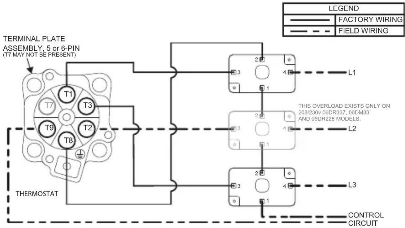
Fig. 26 — Three Phase Electromechanical Overcurrent Protection (Overload XL 6-pin Universal)
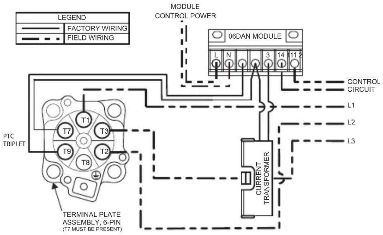
Fig. 27 — Electronic Overcurrent Protection (SERVICE ONLY) Overload 1CT 6-pin Universal
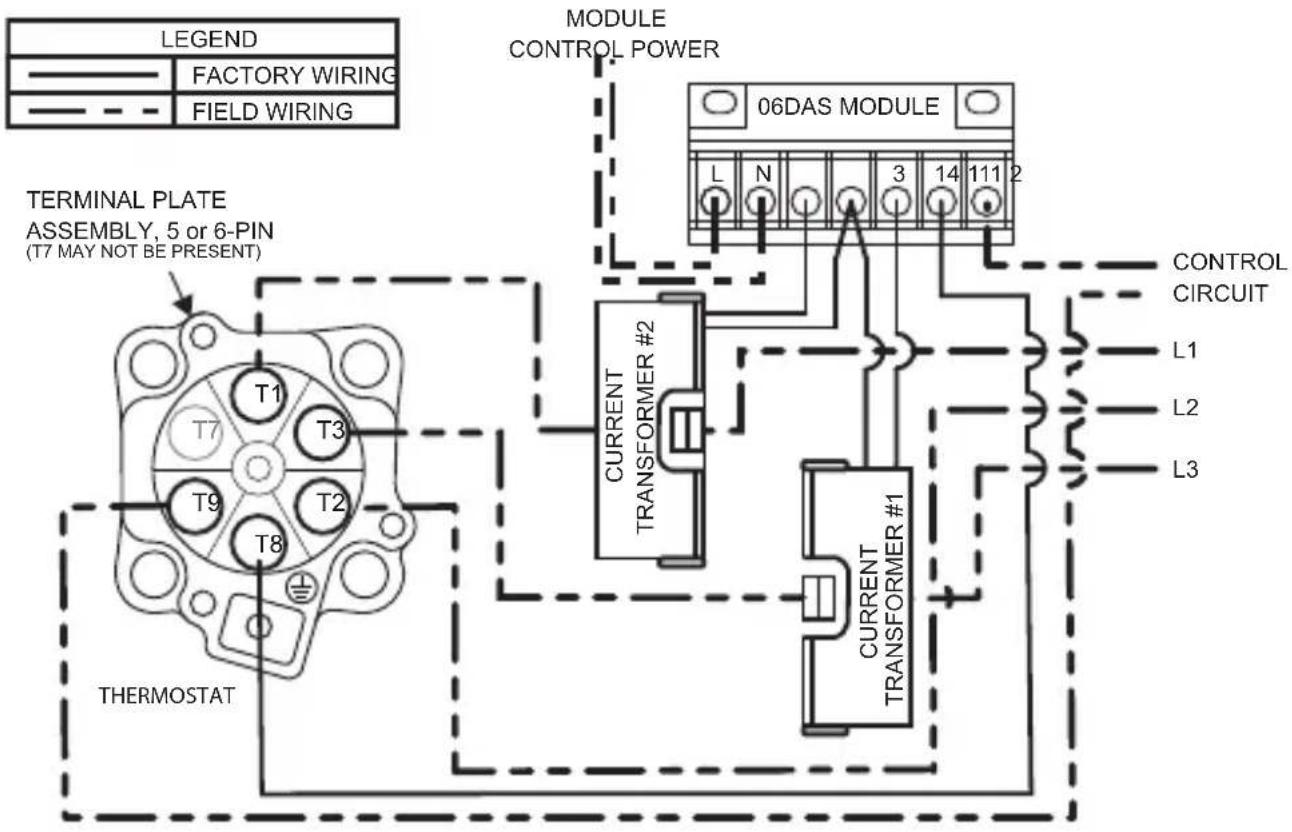
Fig. 28 — Three Phase Electronic Overcurrent Protection (RETROFIT ONLY) Overload 2CT Service
06E COMPRESSORS
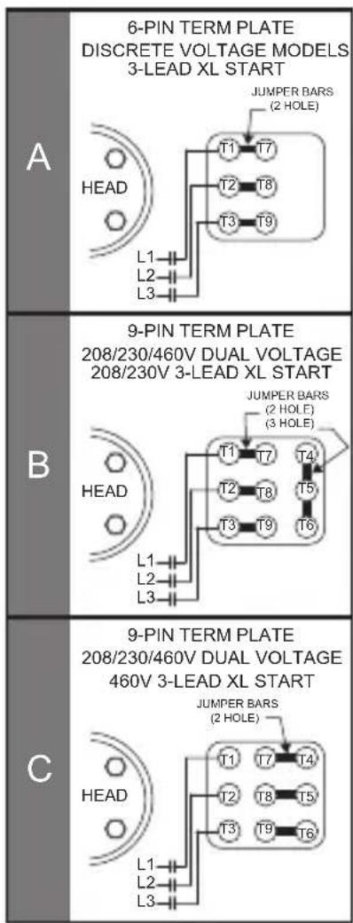
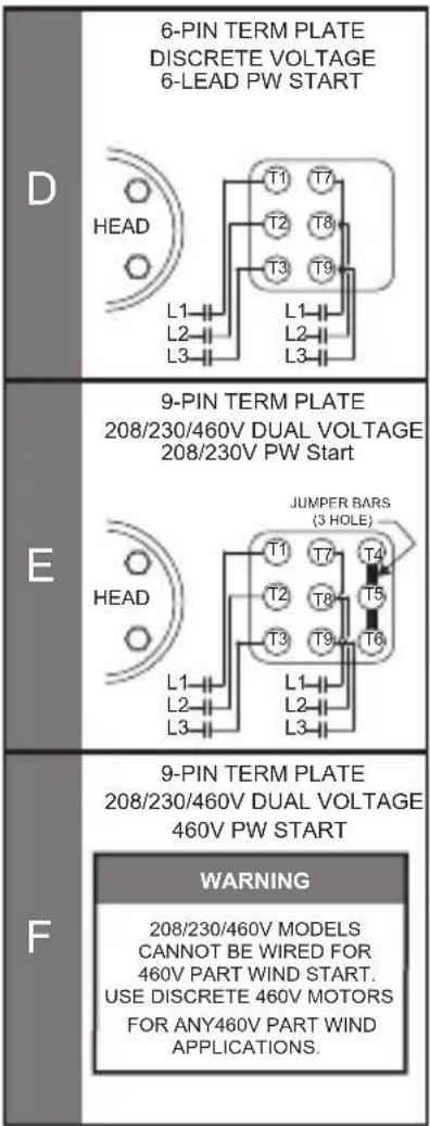
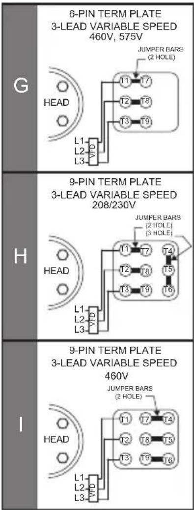
Fig. 29 — Wiring Diagrams-06E Terminal Plate
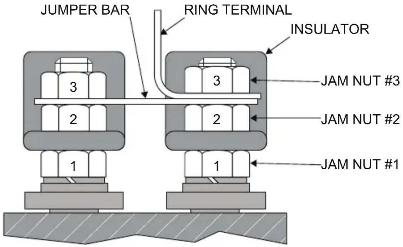
Fig. 30 — Terminal Post Arrangement, Detail View (06E and 06CC 50 to 99 cfm)
4.7 — Voltage and Current Unbalance
VOLTAGE UNBALANCE (Maximum 2%)
Voltage unbalance can cause motors to overheat and fail. Below is the recommended method for determining voltage unbalance.
Example: Supply voltage is 240-3-60
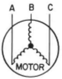
$$ \mathrm{AB} = 2 4 3 \text { volts } $$
$$ \mathrm{BC} = 2 3 6 \text {volts} $$
$$ \mathrm{AC} = 2 3 8 \text {volts} $$
$$ \begin{array}{l} \text { Average Voltage } = \frac {2 4 3 + 2 3 6 + 2 3 8}{3} \ = \frac {7 1 7}{3} \ = 2 3 9 \mathrm{volts} \ \end{array} $$
Determine maximum deviation from average voltage:
$$ (\mathrm{AB}) 2 4 3 - 2 3 9 = 4 \text {volts} $$
$$ (\mathrm{BC}) 2 3 9 - 2 3 6 = 3 \text {volts} $$
$$ (\mathrm{AC}) 2 3 9 - 2 3 8 = 1 \text { volt } $$
Maximum deviation is 4 volts.
Determine % voltage unbalance:
$$ \begin{array}{l} \% \text { Voltage unbalance} = 100 \times \frac{4}{239} \ = 1.7 \% \ \end{array} $$
This amount of phase unbalance is satisfactory as it is below the maximum allowable of 2%.
:TNATROPMI If the supp is more than 2%, contact your local electric utility company immediately.
CURRENT UNBALANCE (Maximum 10%)
Voltage unbalance will cause a current unbalance, but a current unbalance does not necessarily mean that a voltage unbalance exists. A loose terminal connection or a build-up of dirt or carbon on one set of contacts (using the example of L1 as the problem leg) would cause a higher resistance on that leg (L1) than on L2 and L3. The current follows the path of least resistance, so the current increases in legs L2 and L3. Higher current causes more heat to be generated in the motor windings.
Percent (\%) of current unbalance is calculated in the same way as voltage unbalance (see the previous section), with a maximum acceptable current unbalance of 10%.
5.0 COMPRESSOR SERVICE WORKSHEETS
Carlyle recommends that the Compressor Service Worksheets (pages 130 and 131) be copied (and enlarged, if preferred) and filled out for each compressor at initial start-up and each time the compressor is serviced. Comparing the data from current worksheets to past records will allow the service technician to diagnose system changes and prevent compressor failures. This information is also very useful in preventing a repeat failure.
06D, 06E Compressor Service Worksheet
Mechanic: Date:
From Compressor Nameplate:
Model No.: ____
Serial No.:
Motor No.:
Voltage:
Allow compressor to run for 30 minutes, then obtain the pressures and body temperature at the locations shown below. Check for proper oil return in sight glass.
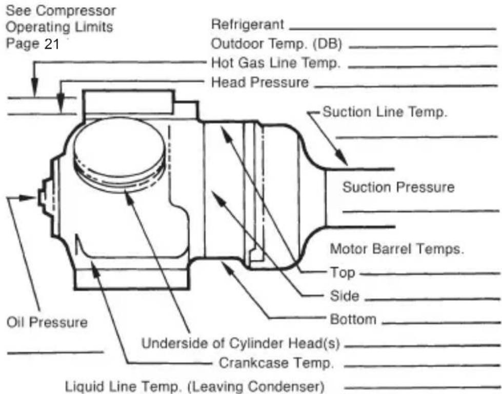
| COMPRESSOR VOLTAGE/AMP VALUES | ||
| PH | VOLTAGE | CURRENT |
| 1 | C-R:____ | C:____ |
| C-S:____ | R:____ | |
| R-S:____ | S:____ | |
| 3 | L1-L2:____ | L1:____ |
| L1-L3:____ | L2:____ | |
| L2-L3:____ | L3:____ | |
| PART WINDING | ||
| L7-L8:____ | L7:____ | |
| L7-L9:____ | L8:____ | |
| L8-L9:____ | L9:____ | |
Make copies of this worksheet to record data at initial start-up and whenever the compressor is serviced.
LEGEND: C - Common R - Run S - Start
06CC Compressor Service Worksheet
Mechanic: Date:
From Compressor Nameplate:
Model No.:
Serial No.:
Motor No.:
Voltage:
Allow compressor to run for 30 minutes, then obtain the pressures and body temperature at the locations shown below. Check for proper oil return in sight glass.
See Compressor Operating Limits, page 22.
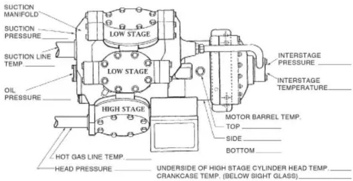
| COMPRESSOR VOLTAGE/AMP VALUES | ||
| PH | VOLTAGE | CURRENT |
| 1 | C-R:____ | C:____ |
| C-S:____ | R:____ | |
| R-S:____ | S:____ | |
| 3 | L _1 -L _2 :____ | L _1 :____ |
| L _1 -L _3 :____ | L _2 :____ | |
| L _2 -L _3 :____ | L _3 :____ | |
| L _7 -L _8 :____ | L _7 :____ | |
| L _7 -L _9 :____ | L _8 :____ | |
| L _8 -L _9 :____ | L _9 :____ | |
Make copies of this worksheet to record data at initial start-up and whenever the compressor is serviced.
LEGEND: C - Common R - Run S - Start
6.0 — SMART CONTROLLER and PWM VALVE
See Application Guide 574-078 at www.carlylecompressor.com.

Application Guide 574-078
https://www.shareddocs.com/hvac/docs/2002/Public/08/574-078.pdf
In refrigeration applications where the thermal load may vary over a wide range, a means of precise capacity control is always desirable for optimum system performance, while maintaining low energy consumption. To meet these objectives, Carlyle has developed an innovative and efficient solution — the smart controller and pulse width modulation (PWM) valve. These new devices meet the demand for precise suction pressure control by modulating system capacity for all low, medium, and high temperature applications, providing leading edge performance in compressor cycling reduction, compressor life extension, and refrigeration system energy usage.
The smart unloading controller allows continuous modulation of the compressor capacity using the steps of mechanical unloading or PWM valve. An analog output signal from the system rack controller provides a 0 to 10 vdc signal to the smart controller. Based on the signal, the smart controller continuously modulates the compressor unloader coils to deliver an equivalent linear change in the compressor capacity output to precisely meet the load demand. In addition, the smart controller will control dis-
charge temperature by operating the accessory cylinder head fan and liquid injection valve as required, maintaining safe and reliable operation. If discharge temperature exceeds allowable limits, the smart controller will automatically turn the compressor off to protect against compressor failure.
The smart controller is designed to operate a special sole-noid valve installed in the compressor's suction line using pulse width modulation. As it does this, the smart controller will cycle the valve once every 30 seconds between the open (loaded) and closed (unloaded) positions. The relative duration of the loaded versus unloaded times creates a time average flow rate from the compressor that can be continuously varied. In turn, the time average flow rate from the compressor allows it to more precisely match the compressor capacity to the system cooling demand. A small bleed port in the solenoid valve keeps the compressor from pulling into a deep vacuum when the valve is in the closed position.
SERVICE GUIDE INDEX
Page
06CC (16 to 37 cfm) 3-Phase Electrical Specifications .... 120
06CC (50 to 99 cfm) 3-Phase Electrical Specifications 123
06CC (16 to 37 cfm) Torque Guide 58
06CC (50 to 99 cfm) Torque Guide 59
06CC Compressor 2-stage (17 to 37 cfm) Model, Connection Points — D Body .... 50
06CC Compressor 2-stage (50 to 99 cfm) Model, Connection Points ..... 51
06CC Compressor Model Numbers 8
06CC Compressors — Physical Data 64
06CC Service Worksheet 131
06D 2-Cylinder Compressor, Connection Points.... 47
06D 4-Cylinder Compressor, Connection Points.... 48
06D 6-Cylinder Compressor (25, 28, 37 and 41 cfm), Connection Points 48
06D 6-Cylinder Compressor, Exploded View 54
06D Compressor, Cross-Sectional View 53
06D and 06CC (16-37 cfm) Electronic Overcurrent Protection ...... 124
06D Compressor Model Numbers 6
06D Compressors — Physical Data 60
06D Compressors — Torque Guide 58
06D Electromechanical Overcurrent Protection 124
06D, E Service Worksheet 130
06D 3 Phase Electrical Specifications Retrofit Only 125
06D 3 Phase Electrical Specifications 124
06D Single-Phase Electrical Specifications.... 125
06E 4-Cylinder Compressor (50 cfm), Connection Points.... 49
06E 6-Cylinder Compressor (65-99 cfm), Connection Points.... 49
06E 6-Cylinder Compressor, Exploded View 56
06E Compressor, Cross-Sectional View 53
06E Compressor Model Numbers 7
06E Compressors — Physical Data 62
06E Compressors — Torque Guide 59
06E (PSG Condensed) 3 Phase Electrical Specifications.... 118
06E (PSG Condensed) 50-99 cfm 3 Phase Electrical Specifications..... 123
Additives, Oil.... 68
Alkylbenzene Oil, Use with CFC.... 68
Baffle Plates 99
Bearing Head (Oil Pump), Replacement Procedures 06D Compressor.... 42
Bearing Head (Oil Pump), Replacement Procedures 06E Compressor.... 43
Bearing Head High Flow Oil Pump 67
Bearing Head, Old 41
Bearing Head, Replacement 69
Billing and Credit 13
Capacity Control Unloading Accessory Packages 87
Capacity Control Coil Packages 90
CFCs, Approved for Use 46, 66, 69
cfm Designation....8
Clean-Up 44
Compressor Isolation.... 24
Compressor Model Number Significance.... 6
Compressor Mounting Data.... 91
Compressor Problems — see "Troubleshooting" 23
Compressors Bodies without Oil 66
Connection Points, 06CC 16 to 37 cfm Models....50
Connection Points, 06CC 50 to 99 cfm Models.... 50
Connection Points, 06D 2-Cylinder Models.... 47
Connection Points, 06D 4 and 6-Cylinder Model.... 48
Connection Points, 06E 4-Cylinder Models 49
Connection Points, 06E 6-Cylinder Models 49
Crankcase Heaters....90
Current Unbalance 128
Cycling, Continuous — Typical Causes 27
Cycling, Intermittent — Typical Causes.... 26
Cylinder Head, Blown 26
Cylinder Head Cooling Fans 86
Cylinder Head Disassembly 36
Cylinder Head Gasket — Failure Causes.... 26
Cylinder Head Gaskets.... 94
Cylinder Head Reassembly 39
Discharge Gas Temperature Sensor 84
Electrical Hookup, 06D and 06CC (17-37 cfm) Compressors ...... 124
Electrical Hookup, 06E Compressors.... 126
Electrical Specifications 111
Electronic Oil Pressure Safety Switch 69
Electronic Overcurrent Protection — Service Replacement Kit...... 111
Electronic Overcurrent Protection — Service Retrofit Kit (Single-Phase) 125
Electronic Overcurrent Protection — Service Retrofit Kit (Three-Phase) 125
Flooding — Typical Causes.... 27
Gasket, Sensor Block 95
Gasket, Terminal Plate 95
Gaskets, Cylinder Head and Valve Plates.... 94
Gaskets, Service Valves.... 96
Gaskets, Leak Testing.... 35
Heaters, Crankcase....90
Help — Where to Get More .... 3
HFCs, Approved for Use 66, 67
Insertion Heaters 91
Interstage Pressure Tables (06CC).... 105
Jumper Plate Packages Connection 98
Locked Rotor, Cycling On — Typical Causes 30
Low Compressor Capacity 25
Metric Conversions and Measurements 8
Mineral Oils, To Use With CFC Refrigerants 66
Model Number 6,10
Motor Burnout.... 30
Motor Barrel Interconnection 18
Motor End Mounting Foot 93
Motor Burnout — Clean-up Procedure 44
Motor Protection Tripping — Typical Causes 29
Mounting Data, Compressor.... 91
Mufflers....97
Nameplate Significance.... 10
OEM 13,15
Oil Additives....68
Oil Charge 61
Oil Control — Parallel Compressor Applications 17
Oil Control — Motor Barrel Interconnections.... 18
Oil Drain Plug Adapter....92
Oil Equalization — Sight Glass Adapters for 92
Oil Pressure 68
Oil Pressure Problems — Typical Causes ...... 34
Oil Pressure Safety Switch 69
Oil Pressure Safety Switch LED Flash Codes 83
Oil Pressure Safety Switch Operation 79
Oil Pressure Safety Switch Technical Specifications 79
Oil Pressure Safety Switch Wiring Diagram 79
Oil Pump – See Bearing Head 69
Oil Sensor Block Installation.... 75
Oil Viscosity and Pour Points 68
Oils, Approved for Use 66
Operating Limits, Typical — 06CC 22
Operating Limits, Typical — 06D, E 21
Overcurrent Protection for 06D Compressors 111
Parallel Compressor Applications, Oil Control.... 16
Parts Identification — 06D Compressor, Exploded View .... 54
Parts Identification — 06E Compressor, Exploded View.... 56
Physical Data — 06CC Compressors .... 64
Physical Data — 06D Compressors 60
Physical Data — 06E Compressors 62
Pipe Rattles — Typical Causes 28
Piston, Suction Valve, and Backer Positions 39
POE Oils, To Use with HFC Refrigerants.... 66
Pump End Bearing Head 42
Pre Start-Up Procedures 15
PWM Valve Installation and Operation 132
Rated Load Amps (RLA) 113
Refrigerants and Oils for 06CC Compressors 66
Refrigerants and Oils for 06D, E Compressors 66
Sensor Block Gasket 95
Serial Number.... 11
Service Billing.... 13
Service Procedures 35
Service Procedures — Bearing Head (Oil Pump) 39
Service Procedures — Cylinder Head and Valve Plate Assembly ...... 41
Service Procedures — Motor Burnout Clean Up 44
Service Replacement Kits 111
Service Retrofit Kits (Single-Phase) 112
Service Retrofit Kits (Three-Phase).... 112
Service Valve Gaskets 96
Service Valves....96
Service Worksheet, 06CC 131
Service Worksheet, 06D, E 130
Sight Glass Adapters — Oil Equalization 92
Sight Glass, Oil Level 16
Sight Glass Replacement — Installation Tool 93
Special Order Number.... 10
Start-Up — Before Starting.... 15
Start-Up — Recommended Procedures.... 15
Start-Up, Compressor.... 19
Start-Up, Troubleshooting and Service 23
Start-Up, Will Not Start 25
Strap-On Heaters 90
Suction Cut-Off Control 87
Suction Valve.... 38, 39
Technical Assistance, OEM.... 15
Terminal Lug Package....98
Terminal Plate Gasket 98
Terminal Plate Jumper Bars, 06E 06CC (50 to 99 cfm) 98
Terminal Posts.... 127
Torque Guide — 06D and 06CC (16 to 37 cfm) Compressors.... 58
Torque Guide — 06E and 06CC (50 to 99 cfm) Compressors.... 59
Troubleshooting.... 25
Troubleshooting — 06CC Desuperheater Connection Hot ...... 33
Troubleshooting — 06CC Discharge Pressure = Intermediate Pressure .. 34
Troubleshooting — 06CC Economizer Connection Hot 33
Troubleshooting — 06CC High Midstage Pressure.... 33
Troubleshooting — 06CC Intermediate Pressure = Discharge Pressure.. 34
Troubleshooting — 06CC Low Midstage Pressure .... 33
Troubleshooting — Cannot Pull Down 26
Troubleshooting — Compressor Isolation Procedures.... 24
Troubleshooting — Cycling, Continuous 27
Troubleshooting — Cycling, Intermittent 26
Troubleshooting — Cylinder Head Gasket 26
Troubleshooting — Desuperheater Connection Hot, 06CC ...... 33
Troubleshooting — Discharge Temperature Sensor 29
Troubleshooting — Economizer Connection Hot, 06CC .... 33
Troubleshooting — Flooding 27
Troubleshooting — Locked Rotor, Cycling On 30
Troubleshooting — Low Discharge Pressure 27
Troubleshooting — High Midstage Pressure, 06CC.... 33
Troubleshooting — Low Midstage Pressure, 06CC 33
Troubleshooting — Low On Capacity.... 25
Troubleshooting — Low or No Oil Pressure 28
Troubleshooting — Low Suction Pressure 27
Troubleshooting — Motor Burnout 30
Troubleshooting — Motor Protection Tripping 29
Troubleshooting — No Oil Pressure.... 28
Troubleshooting — Noisy Compressor.... 28
Troubleshooting — Oil Safety Switch Tripping 33
Troubleshooting — Parallel Systems 31
Troubleshooting — Pipe Rattle.... 28
Troubleshooting — Running Hot 32
Troubleshooting — Sight Glass, Low or Empty 33
Troubleshooting — Starting Problems.... 23
Troubleshooting — Valve Plates 26
Troubleshooting — Will Not Start 25
Troubleshooting Guide 25
Unloading — Capacity Control 87
Valve Plate Gaskets 94
Valve Plate Gaskets, Blown 26
Valve Plate Disassembly 36
Valve Plate Packages....96
Valve Plates — Failure Causes.... 26
Valve Plates — Replacement Procedures 35
Valve Plates — Leak Testing 35
Voltage Unbalance 128
Warranty 13
Weight, Compressor 61
COMPLIMENTS OF:
Carlyle service replacement compressors, parts, and support are available through a wide distribution network. Technical support is provided by your local distributor. Customer Service Representatives can provide assistance in locating your nearest distributor.
USA www.Totaline.com

CANADA www.wwgtotaline.ca/ en/branch

MEXICO www.totalinecom.mx/ pages/Sucursales.html

www.CarlyleCompressor.com
© 2023 Carrier
Manufacturer reserves the right to discontinue, or change at any time, specifications or designs without notice or without incurring obligations.

- WHAT THIS GUIDE CAN DO FOR YOU
- DANGER
- WARNING
- CAUTION
- CARLYLE COMPRESSOR THANKS YOU FOR SELECTING OUR EQUIPMENT
- HOW TO USE THIS GUIDE
- TO GET MORE HELP
- CONTENTS
- GENERAL COMPRESSOR AND CUSTOMER INFORMATION
- START-UP, TROUBLESHOOTING, AND SERVICE
- COMPRESSOR AND PARTS DATA
- ELECTRICAL DATA
- COMPRESSOR SERVICE WORKSHEETS
- SMART CONTROLLER and PWM VALVE..... 132
- SERVICE GUIDE INDEX...... 134
- — GENERAL COMPRESSOR AND CUS- TOMER INFORMATION
- — Compressor Model Number Significance
- 06D COMPRESSORS
- 06E COMPRESSORS
- Design Variable:
- Electrical Characteristics:
- Motor Size and Protection:
- Compressor Type:
- NOTE: METRIC MEASUREMENTS
- Application Range
- — Nameplate Significance
- — Compressor Serial Number Significance
- ALL NEW COMPRESSORS
- ALL SERVICE COMPRESSORS
- NEW AND SERVICE REPLACEMENT
- COMPRESSORS BUILT BETWEEN
- — Carlyle OEM Compressor Warranty
- — Service Billing and Credit
- — Carlyle Service Replacement Compressors, Parts, and Support
- 2.0—START-UP, TROUBLESHOOTING, AND SERVICE
- — Technical Assistance - Carlyle OEM Compressors
- — Recommended Start-Up Procedure
- COMPRESSOR START-UP
- COMPRESSOR OPERATING LIMITS
- — Troubleshooting Procedure
- COMPRESSOR ISOLATION
- LEGEND
- — Service Procedures
- REMOVE, INSPECT AND REPLACE CYLINDER HEAD AND VALVE PLATE ASSEMBLY
- DISASSEMBLY
- REASSEMBLY
- REMOVE, INSPECT AND REPLACE BEARING HEAD ASSEMBLY
- MOTOR BURNOUT CLEAN-UP PROCEDURE
- — Connection Points, 06D, 06E, and 06CC Compressors
- Connection Points
- — Exploded View - 6-Cylinder 06D Compressor
- — Exploded View - 6-Cylinder 06E Compressor
- — COMPRESSOR AND PARTS DATA
- — 06D Series Compressors - Physical Data (Page 1 of 2)
- — Refrigerants and Oils for 06D, E, CC Compressors
- NOTES:
- — Oil Viscosity and Pour Points
- — Oil Additives
- — Oil Pressure
- — Replacement Oil Pump/Pump End Bearing Package
- — Oil Pressure Safety Switch
- Replacement Parts:
- OPSS Function:
- OPSS Operation:
- Oil Sensor Block Installation (06D/E/CC)
- LED Status Table and Flash Codes
- OPSS Removal
- — 06CC, E Discharge Gas Cylinder Head Temperature Sensor and 06E Pressure Relief Valve
- Pressure Relief Valve
- Part Number Description
- — 06D, E Cylinder Head Cooling Fans, and Liquid Injection
- — Capacity Control Accessory Packages (Suction Cut-Off Unloading Type)
- — Capacity Control Coil Packages (06D, E)
- — Crankcase Heater Data
- STRAP-ON HEATERS:
- INSERTION HEATERS:
- — Compressor Mounting Data
- — Compressor Service Valves and Gaskets (06D, E, CC)
- — Oil Drain Plug Adapter
- — Sight Glass Adapters for Oil Equalization
- 3.19— Replacement Sight Glass/Installation Tool
- — Replacement Motor End Mounting Foot
- — Miscellaneous
- Terminal Plate Gasket
- OPSS Sensor Block Gasket
- Electrical Terminal Barrel Nut Tool (Socket tool used for installation for terminal nuts)
- — Muffler Recommendations
- — Electrical Accessories
- — Baffle Plate Recommendations
- NEW CONSOLIDATED BAFFLE PLATE KITS
- BAFFLE PLATE ADVANTAGES:
- BAFFLE PLATE LIMITATIONS
- Application Note:
- — Interstage Pressure Tables (06CC Compressors Only)
- — ELECTRICAL DATA
- — 06D and 06CC (16-37 cfm) Electronic Overcurrent Protection
- RETROFIT KITS:
- — 06D 3-Phase Electrical Specification
- Legend and notes for Table 4.2
- Legend and notes for Table 4.3.
- Legend and notes for Table 4.4.
- — 06CC-E (50-99 cfm) 3-Phase Electrical Specification
- — Electrical Hook-Up
- 06D and 06CC (17-37 cfm) COMPRESSORS
- — Voltage and Current Unbalance
- VOLTAGE UNBALANCE (Maximum 2%)
- CURRENT UNBALANCE (Maximum 10%)
- 06D, 06E Compressor Service Worksheet
- 06CC Compressor Service Worksheet
- — SMART CONTROLLER and PWM VALVE
- SERVICE GUIDE INDEX
- Page
- COMPLIMENTS OF:
Brand : CARRIER
Model : 06E
Category : Compressor