
6018 - Multimeter Kyoritsu - Free user manual and instructions
Find the device manual for free 6018 Kyoritsu in PDF.


| Product Type | Insulation and Earth Resistance Tester (Multimeter) |
| Brand | Kyoritsu |
| Model | 6018 |
| Dimensions | 130 x 183 x 100 mm |
| Weight | Approx. 1000 g (batteries included) |
| Power Source | Eight 1.5V batteries, type R6P (AA) or equivalent |
| Maximum Power Consumption | 3.5 VA |
| Insulation Resistance Ranges | 250V/50 MΩ, 500V/100 MΩ, 1000V/2000 MΩ |
| Earth Resistance Ranges (Precision) | 12 Ω (x1), 120 Ω (x10), 1200 Ω (x100) |
| Earth Resistance Ranges (Simplified) | 12 Ω, 120 Ω, 1200 Ω |
| AC Voltage Range | 0-600 V AC (50/60 Hz) |
| Earth Voltage Range | 0-60 V AC |
| Accuracy (Insulation Resistance) | ±5% of indicated value (primary effective measuring range) |
| Accuracy (Earth Resistance) | ±3% of full scale value |
| Overload Protection | 1200 V AC (insulation 1000V range), 600 V AC (other insulation ranges), 250 V AC (earth ranges), 750 V AC (ACV), 250 V AC (earth voltage) |
| Withstand Voltage | 5160 V AC (50/60 Hz) for 5 seconds between internal circuit and enclosure |
| Safety Standards | IEC 61557-2, IEC 61557-5, IEC 61010-1 CAT III 600V, Pollution degree 2 |
| Operating Temperature | 0 to +40°C, 80% RH or less (no condensation) |
| Accessories Included | Test leads (Model 7103A with remote switch), safety alligator clip (7131B), flat test prod (7161A), pouch (9092), extension prod (8017), 8 R6P batteries, shoulder strap, instruction manual |
| Cleaning | Use a damp cloth with detergent; avoid abrasives or solvents |
| Repairability | Do not modify; return to Kyoritsu or distributor for repair/recalibration |
Frequently Asked Questions - 6018 Kyoritsu
User questions about 6018 Kyoritsu
0 question about this device. Answer the ones you know or ask your own.
Ask a new question about this device
Download the instructions for your Multimeter in PDF format for free! Find your manual 6018 - Kyoritsu and take your electronic device back in hand. On this page are published all the documents necessary for the use of your device. 6018 by Kyoritsu.
USER MANUAL 6018 Kyoritsu
5-1 Installing Batteries 9
5-2 Mechanical Zero Adjustment 10
5-3 Connecting Test Leads 10
5-4 Battery Voltage Check 11
5-5 "Power-on"Indication LED 11
5-6 Scale Illumination Function 12
5-7 Attaching Neck Strap 12
5-8 Fitting Case Lid Under Case 13
- Measurement
6-1 AC Voltage Measurement (Mains Disconnection Check) 14
6-2 Insulation Resistance Measurement 16
6-3 Continuous Insulation Resistance Measurement 18
6-4 Output Voltage Characteristics 18
6-5 Earth Resistance Measurement 19
6-6 Precision Measurement 19
6-7 Simplified Measurement 21
- Test Prods for Line Probe and Replacement 24
- Adapters for Earth Lead and Replacement 25
- Optional Accessories
9-1 How to Use Test Leads and Cord Reels 26
- Cleaning Meter Cover 27
- Before Sending for Repair 28
1. Safety Warnings
This instruction manual contains warnings and safety rules which must be observed by the user to ensure safe operation of the instrument and to retain it in safe condition. Therefore, read through these operating instructions before using the instrument. This instrument has been designed and tested according to the following standards.
IEC 61557-2: Insulation Tester
IEC 61557-5: Earth Resistance Tester
IEC 61010-1 measurement category CAT III 600V, pollution degree 2
Symbol ⚠️ indicated on the instrument means that the user must refer to related parts in the manual for safe operation of the instrument. Be sure to carefully read the instructions following each ⚠️ symbol in this manual.
⚠️ DANGER is reserved for conditions and actions that are likely to cause serious or fatal injury.
⚠ WARNING is reserved for conditions and actions that can cause serious or fatal injury.
⚠️ CAUTION is reserved for conditions and actions that can cause injury or instrument damage.
WARNING
- Read through and understand instructions contained in this manual before using the instrument.
- Save and keep the manual handy to enable quick reference whenever necessary.
- The instrument is to be used only in its intended applications. Understand and follow all the safety instructions contained in the manual. Failure to follow the instructions may cause injury, instrument damage and/or damage to equipment under test. Kyoritsu is by no means liable for any damage resulting from the instrument in contradiction to this cautionary note.
! DANGER
● Never make measurement on a circuit above 600VAC or DC.
- Do not attempt to make measurement in the presence of flammable gasses. Otherwise, the use of the instrument may cause sparking, which can lead to an explosion.
- When testing a circuit that can carry high current, including a power line, be sure to make voltage measurement at the secondary side of a circuit breaker in order to avoid possible hazard to the user. Exercise extreme caution not to short live conductors together with the metal tips of test probes.
● Never attempt to use the instrument if its surface or your hand is wet.
- Do not exceed the maximum allowable input of any measurement range.
● The instrument should be used only in its intended applications or conditions. Otherwise, safety functions equipped with the instrument do not work, and instrument damage or serious personal injury may be caused.
- Verify proper operation on a known source before use or taking action as a result indication of the instrument.
● Never open the battery compartment cover when making measurement.
- Keep your fingers and hands behind the protective fingerguard during measurement.

WARNING
- Never use the instrument, if any abnormal conditions are noted, such as broken case, cracked test leads and exposed metal parts.
- Never press the test button while making connection to the circuit under test.
- Do not install substitute parts or make any modification to the instrument. Return the instrument to Kyoritsu or your distributor for repair or re-calibration.
- In order to avoid possible electric shock hazard, do not touch the circuit under test during and shortly after insulation testing. Wait until electric charges stored in the circuit are completely discharged.
- Do not try to replace the batteries if the surface of the instrument is wet.
- Make sure to insert the test probe connector fully into the socket on the instrument. To remove the test leads, hold and pull the connector out of the socket.
- Never pull the leads in order to avoid any damage that can lead to electric shock hazard.
- Switch off the instrument and remove the test leads from it before opening the battery compartment cover for battery replacement.
- Stop using the test lead if the outer jacket is damaged and the inner metal or color jacket is exposed.

CAUTION
- Make sure that the function selector switch is set to an appropriate position before making measurement.
- Do not turn the function selector switch with the test leads connected to the circuit under test.
- Be sure to set the function selector switch to the "OFF" position after use.
When the instrument will not be in use for a long period of time, place it in storage after removing the batteries. This is to avoid damage to the instrument by possible leakage from the batteries. - Do not expose the instrument to the direct sun, temperatures of 50: or greater, or dew fall. Placing the instrument in temperatures of 50: or greater can cause the instrument's case to deform and result in operation failure.
- Use a damp cloth and detergent for cleaning the instrument. Do not use abrasives or solvents.
2. Features
Model 6018 (KEW-MEG-EARTH) are a versatile tester designed for insulation and earth resistance measurements on low voltage installations, wiring systems and electric appliances rated at up to 600V. It also has AC and earth voltage measurement capabilities.
- Five major functions in one unit
Insulation resistance: 250V/500V/1000V
Earth resistance: 12/120/1200Ω
Earth resistance simplified measurement: 12/120/1200Ω
AC voltage: 600VAC
Earth voltage: 60VAC
- When 1000V range of insulation resistance tester is set, the high voltage warning is made by the buzzer beeping (intermittent tone). (Model-6018 only)
- After insulation testing, automatically releases electric charges stored in the capacitance of the circuit under test. Discharging can be checked by the meter indication.
- Scale illumination to facilitate working at dimly lit situations.
- Easy-to-read meter scales coded in color matching the position of the function selector switch.
- On insulation resistance, earth resistance, earth voltage or BATT CHECK ranges "power-on" indication LED illuminates in red to warn the user of voltage output. On earth resistance ranges, "OK" lamp lights up in green when the instrument is ready for accurate earth resistance measurement.
- Test leads furnished with a remote control switch and exchangeable probe tip. One pair of test probes can be used both in insulation resistance testing and in simplified earth resistance testing, facilitating field work.
- Sliding shutter to avoid incorrect use of terminals for improved safety.
- Case made of shock resistant elastomer.
- Optional cord reels and auxiliary earth bars enable precision earth resistance measurement.
- Neck strap permits two hand operation for easy and safety field work.
3. Specifications
3-1 Standards
Designed to meet:
IEC 61557-2: Insulation Tester
IEC 61557-5: Earth Resistance Tester
IEC 61010-1, -2-030 measurement category CAT III 600V, pollution degree 2
IEC 61326-1, 2-2-2 (EMC)
EN50581 (RoHS)
IEC 61010-031
MODEL7103A CAT III 600V (with M-8256)
CAT II 1000V (with M-8072)
CAT II 1000V (with M-8017A)
CAT III 600V (with alligator clip)
CAT II 600V (with flat test prod)
(Only the environment of CAT III or higher can be used with M-8256 and the alligator clip)
※When the instrument and the test lead are combined and used together, whichever lower category either of them belongs to will be applied.
3-2 Insulation Resistance Ranges and Accuracy
| Function | 1000V/2000MΩ | 500V/100MΩ | 250V/50MΩ |
| Rated Test Voltage | 1000V | 500V 250V | |
| Measuring Range | 0-2000MΩ | 0-100MΩ | 0-50MΩ |
| Mid-scale Value | 50MΩ | 2MΩ | 1MΩ |
| Output Voltage at Open Circuit | 1000VDC+20% - 0% | 500VDC+20% - 0% | 250VDC+20% - 0% |
| Short-circuit Current | 1-1.6mADC or less(Measured with an ammeter with a voltage drop of 500mV or less) | ||
| Rated Test Current | at 1MΩ | at 0.5MΩ | at 0.25MΩ |
| 1-1.2mADC or less(Measured with an ammeter with a voltage drop of 500mV or less) | |||
| Accuracy in Primary Effective Measuring Range | 2-1000MΩ | 0.1-50MΩ | 0.05-20MΩ |
| ± 5% of indicated value | |||
| Accuracy in Secondary Effective Measuring Ranges | Ranges other than the above range, 0 and∞ | ||
| ±10% of indicated value | |||
| Accuracy at 0 and∞ | 0.7% of scale length | ||
3-3 Earth Resistance Ranges and Accuracy: Precision Measurement
| Function | X 1 Ω | X 10 Ω | X 100 Ω |
| Measuring Range | 0-12Ω | 0-120Ω | 0-1200Ω |
| Accuracy | ±3% of full scale value(The earth resistance at auxiliary earth spike is within 10k Ω) | ||
| Output Current | 2.5mA AC max., 820 ± 10Hz | ||
3-4 Earth Resistance Ranges and Accuracy: Simplified Measurement
| Function | X 1 Ω | X 10 Ω X 100 Ω | |
| Measuring Range | 0-12 Ω 0-1 | 20 Ω 0-1200 Ω | |
| Accuracy | ±3% of full scale value(Value subtracted test lead resistance) | ||
Output current is the same as in precision measurement.
3-5 AC Voltage Ranges and Accuracy
| Function | 600V AC | Earth Voltage: 60V AC |
| Measuring Range | 0-600V | 0-60V |
| Frequency | 50/60Hz | |
| Accuracy | ±3 % of full scale value | |
3-6 Input Impedance
| Function Input Impedance | |
| 600V AC | 2.8MΩ |
| Earth Voltage: 60V AC | 135kΩ |
3-7 Battery Life
Number of measurements within effective battery voltage range.
(5-second measurement /25-second pause cycle)
| Function Test Resistance | Number of Measurements | ||
| Insulation Resistance | 1000V | 1MΩ | More than 1000 times |
| 500V | 0.5MΩ | More than 2000 times | |
| 250V | 0.25MΩ | More than 3000 times | |
| Earth (3 Pole) | X 100 Ω | 1200Ω | More than 3000 times |
| Earth (2 Pole) X 100 Ω | 1200Ω | More than 4000 times | |
3-8 General Specifications
- Operating Temperature
- Storage Temperature
- Response Time
- Effect of Temperature
- AC Component in Measuring Terminal Voltage (Insulation resistance ranges)
- Effect of auxiliary earth resistance (Earth resistance ranges)
● Effect of earth voltage (Earth resistance ranges)
- Power Source
● Maximum Power Consumption
- Insulation Resistance
- Withstand Voltage
- Overload Protection
: 0 to +40°C, 80%RH or less, no condensation.
:-10 to +50°C, 75%RH or less, no condensation.
: Insulation resistance ranges: Within 3 sec
Earth resistance ranges: Within 4 sec Insulation resistance measurement on a capacitive load can result in a longer response time.
: Variation in the reading at the points below is ±5% or less when temperature is varied from 20°C to 0°C and to 40°C.
(Primary effective measuring ranges)
: Effects of capacitance elements contained in the object being measured (5μF); Within ±10% of indicated value. Including fluctuations.
: Within ±5% when fluctuation is 0 to 5kΩ
: Within ±5% at 0 to 5V, ±10% at 0 to 10V (50/60Hz)
When there is interference voltage of frequency except 50/60Hz, the indication can be over the tolerance of the operating error.
: Eight 1.5 batteries, type R6P, AA or equivalent.
: 3.5VA
: 100MΩ or greater between the internal circuit and the enclosure when measured with 1000V DC.
: 5160VV AC(50/60Hz) for 5 seconds between the internal circuit and the enclosure.
: The instrument operates properly after the voltages shown in the table below is applied for
| Function Voltage | |
| Insulation Resistance Range | 1000V range:1200V AC |
| Other ranges: 600V AC | |
| Earth Resistance | 250V AC on all ranges |
| AC Voltage | 750V AC |
| Earth Voltage | 250V AC |
- Dimensions
- Weight
- Accessories
: Instrument Body 130(L)x183(W)x100(D)mm.
: Approx. 1000g (batteries included).
: Model 7103A Test Leads with Remote Control Switch
Model 7131B Safety Alligator Clip
Model 7161A Flat test prod
Model 9092 Pouch for Test Leads
Model 8017 Extension Prod
Batteries Eight R6P Batteries
Nooke\$39421 Shoulder strap
Instruction Manual
- Optional Accessories
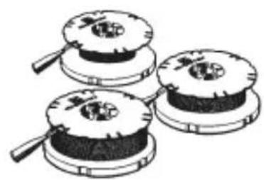
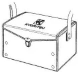
:Model 7100A Test Lead Set for Precision Earth Resistance Measurement (includes Test Leads, Carrying Case, Cord Reels, Auxiliary Earth Bars)
natural_image
Three circular mechanical components with internal holes and a handle, shown in line drawing style (no text or symbols)MODEL 7095+MODEL 8200

MODEL 8032
natural_image
Line drawing of a wooden toolbox with a handle and mounting holes (no text or symbols)MODEL 9091
Model 8016 Pickel Prod
Model 7095 Earth Resistance Test Leads
Model 8032 Auxiliary Earth Bars
Model 8200 Cord Reels
Model 9091 Carrying Case for Cord Reels
4. Instrument Layout
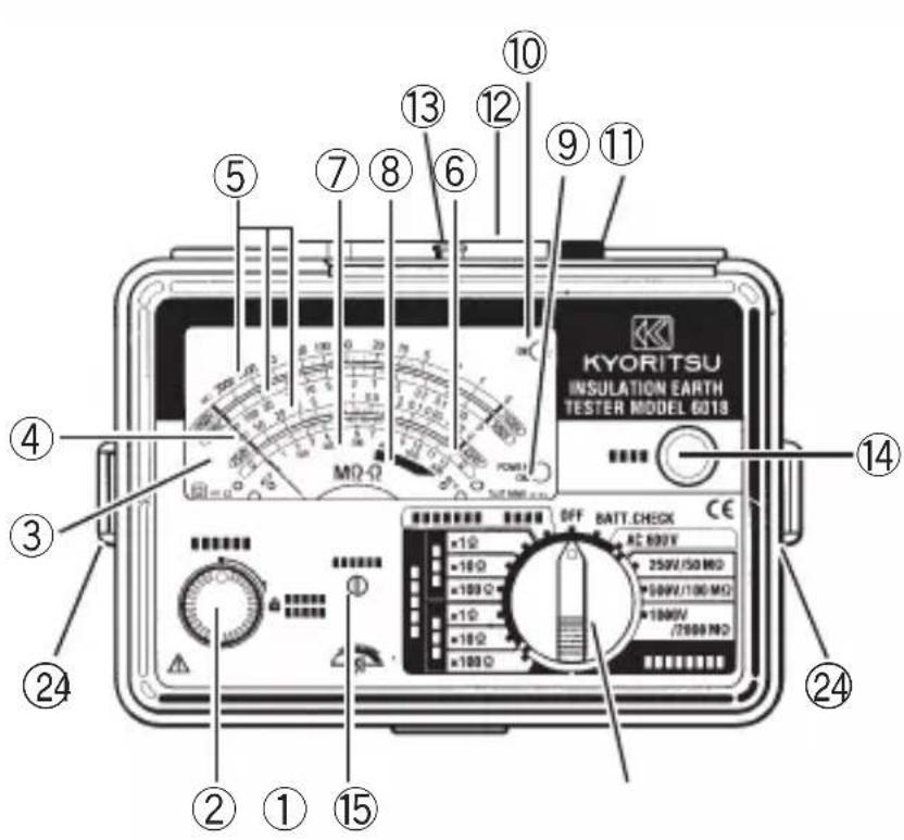

① METER ZERO ADJUSTER
② TEST BUTTON
③ SCALE PLATE
④ METER POINTER
⑤ INSULATION RESISTANCE SCALES
⑥ EARTH RESISTANCE SCALE
⑦ AC VOLTAGE AND EARTH VOLTAGE
SCALES
⑧"BATTERY-OK" AREA
⑨ "POWER-ON" INDICATION LED
⑩ "OK" LAMP
⑪ PROBE SOCKET
⑫ SLIDING SHUTTER
⑬ TERMINALS FOR PRECISION EARTH RESISTANCE MEASUREMENT (Used with Model 7095A, optional Earth Resistance Test Leads)
⑭LIGHT BUTTON
⑮RANGE SELECTOR SWITCH
⑯ SAFETY ALLIGATOR CLIP
⑰BLADE TYPE PROD
⑱REMOTE CONTROL SWITCH
⑲STANDARD TEST PROD
⑳LINE PROBE
②LINE PROBE LEAD WITH REMOTE CONTROL SWITCH
②TEST PROBE CONNECTOR
⑳EXTENSION PROD
⑳LUG FOR NECK STRAP
⑳EARTH LEAD
⑳Protective fingerguard ( It is a part providing protection against electrical shock and ensuring the minimum required air and creepage distances.)
5. Preparation for Measurement
5-1 Installing Batteries
WARNING
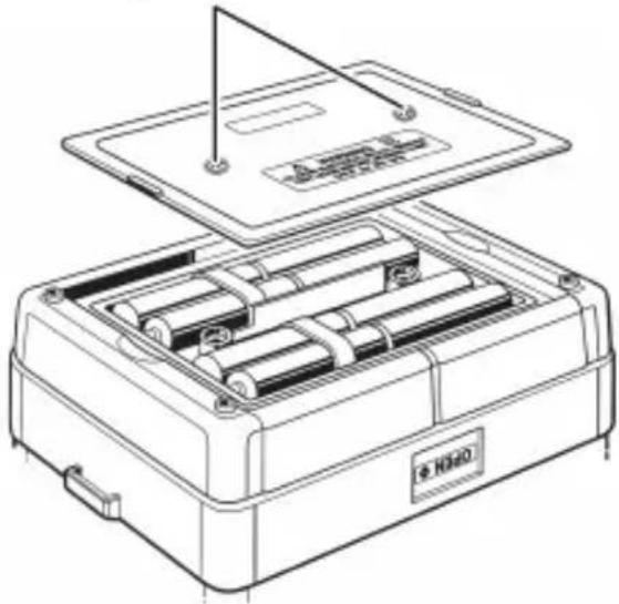
- To avoid possible electric shock hazard, set the function selector switch to the OFF position and remove the test probe connector from the socket before opening the battery compartment cover. After battery replacement, do not use the instrument before securing the cover with the two screws.
- Never mix old and new batteries.
-
Install batteries in correct polarity as shown inside the battery compartment.
-
Set the range selector switch to the OFF position and remove the test probe connector from the probe socket.
- Open the battery compartment cover by removing the two screws on the bottom of the instrument. Replace all eight batteries with new ones.
- Secure the cover in place with the two screws.
Battery-compartment-cover-fixing Screws
natural_image
Line drawing of an open battery pack with cylindrical modules and a lid, no text or symbols presentNote:
- When not in use for a long time, to prevent possible corrosion caused by battery leakage, remove the batteries before storage.
5-2 Mechanical Zero Adjustment
With the function selector switch set to the OFF position and without pressing the test button, turn the zero adjuster with a screw driver so that the pointer lines up with the mark on an insulation resistance scale.
5-3 Connecting Test Leads
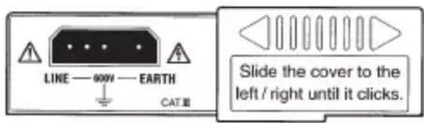
Slide the sliding shutter over the terminals for precision earth resistance measurement to reveal the probe socket. Insert the test probe connector into the probe socket correctly as shown below.
The instrument is shipped with the slide shutter over the terminals for precision earth resistance measurement. Use these terminals only for precision earth resistance measurement.

DANGER
- When the test button or the remote control switch is pressed with the function selector switch set to an insulation or earth resistance range, do not touch the tips of the test probes, where a high voltage is present.
5-4 Battery Voltage Check
- Set the function selector switch to the BATT CHECK position.
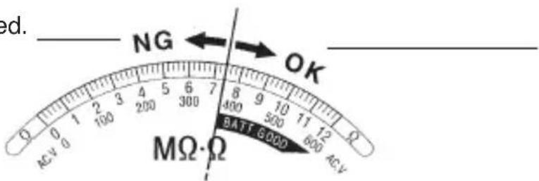
- Press the test button or the remote control switch.
- If the meter pointer does not reach the "BATT GOOD" area, replace the batteries as shown in section 5-1 "Installing Batteries."

CAUTION
- Do not keep the test button pressed or locked down during battery check to avoid battery power drain.
Batteries have exhausted. Replace the batteries.
Proceed to measurement.
5-5 "Power-on" Indication LED
On an insulation resistance, an earth resistance or the BATT CHECK range, when the test button or remote control switch is pressed, the power-on-indication LED (red) lights up, indicating the instrument is in the operation mode. The "power-on" indication LED also lights up on the earth voltage range since a relay incorporated in the instrument is activated.


CAUTION
- In order to conserve battery power, turn the function selector switch back to the OFF position after measurement. Otherwise, the instrument remains in the stand-by mode and consumes battery power. Particularly on the earth voltage range, current consumption is as high as 50mA.
5-6 Scale Illumination Function
To facilitate working in dimly lit situations, a function to illuminate the scale plate is provided. To operate this function, depress and release the light button. The light will be switched on for about 60 seconds before it goes off.
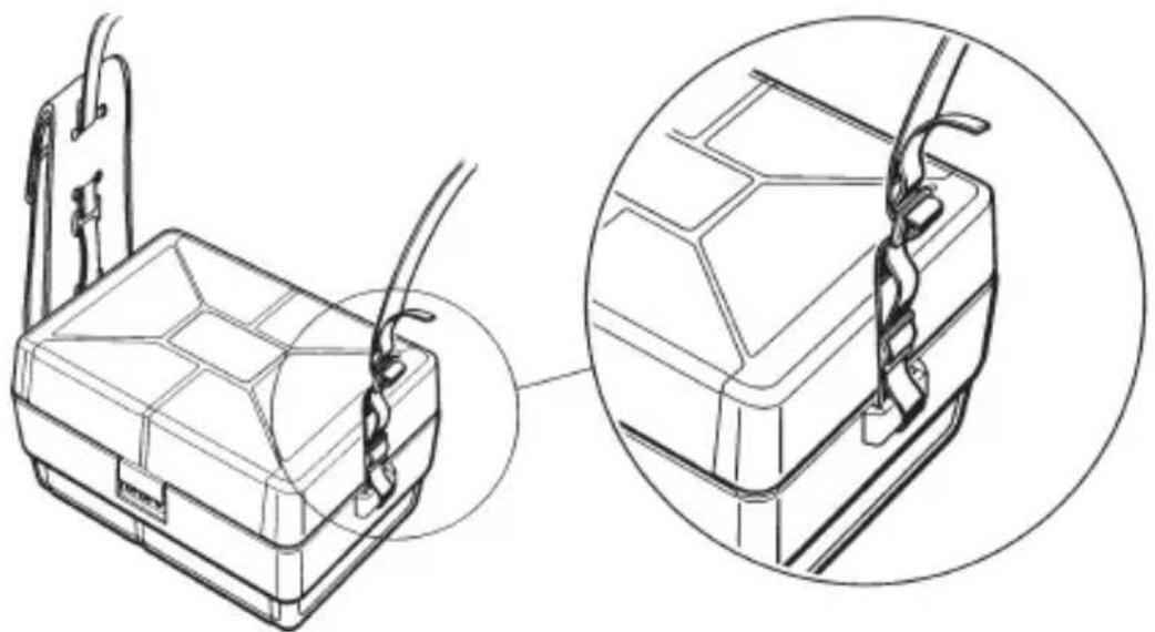
5-7 Attaching Neck Strap
Attaching the provided neck strap permits the use of the instrument with strap hung around the neck. This allows two-hand operation, facilitating field work.
natural_image
Technical line drawing of a mechanical component with two views showing assembly details (no text or symbols)5-8 Fitting Case Lid Under Case

1.Open the case lid as shown.
-
Turn it 180 degrees.
-
Put the case under the housing case.
-
Hook it onto the housing case.
6. Measurement
6-1 AC Voltage Measurement (Mains Disconnection Check)
An AC voltage range is provided for mains voltage measurement. If any voltage is present on the circuit under test in insulation resistance measurement, the display also reads the voltage before the test button is pressed.
Note:
- On any range, the instrument measures and displays AC voltage while the test button is not depressed. However, when you simply make AC voltage measurement, not mains disconnection checks, the AC voltage range should be used. This will avoid possible damage to the circuit under test by inadvertently pressing the test button or the remote control switch to apply a high voltage.
- DC voltage can be measured with the AC voltage measurement function. Take the reading on the AC voltage scale and multiply it by 0.9. The reading does not sense the polarity of DC voltage.

DANGER
- When testing installation with a large current capacity, such as power lines, make sure to make measurement on the secondary side of a circuit breaker in order to avoid possible hazard to the user.
- Never apply the instrument a voltage exceeding the limit for overload protection.
- In order to avoid possible hazard to the user, excise extreme caution not to short live conductors together with the tips of the probes.
- Keep your fingers and hands behind the protective fingerguard during measurement.

CAUTION
- Never press the test button or the remote control switch during mains disconnection checks to avoid possible damage to the circuit under test.
-
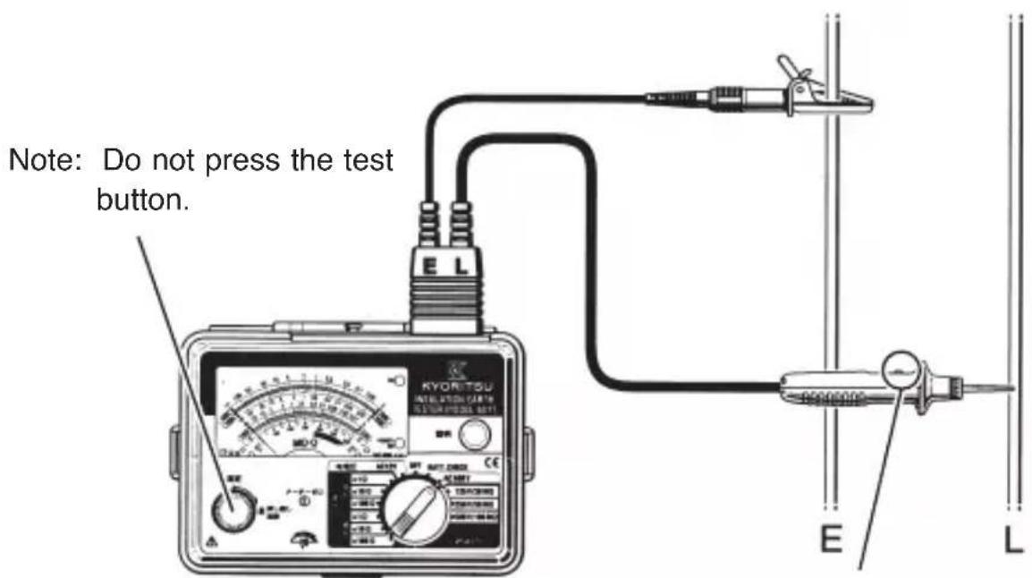
Set the function selector switch to AC600V. Connect the earth probe (alligator clip on black lead) to earth of the circuit under test and the line probe (red) to the other side as shown below. If the circuit is not earthed, connect the earth probe to an appropriate conductor.
-
Do not press the test button or the remote control switch. Take the reading on the AC voltage scale.
-
Set the function selector switch to the OFF position.
Note: Do not press the remote control switch
Note:
- The "OK" lamp does not light up in AC voltage measurement.
6-2 Insulation Resistance Measurement
The insulation resistance function is used for insulation check on electric appliances, wiring systems, etc.
The circuit under test must be disconnected from mains and de-energized before attempting to make measurement. Check the maximum voltage that may be applied to the circuit under test.
Note:
- In some cases, insulation resistance values are not stable, causing the reading to vary during measurement.
- The instrument may generate a high pitch tone during measurement, but this is not a failure.
- If the circuit under test has a large capacitive load, it may take some time before the reading becomes stable for the final value.
- On insulation resistance ranges, DC voltage is supplied through the earth lead and the line probe lead, with the earth lead having positive polarity.
The earth lead should be connected to the earth conductor in the circuit under test. Such connection is known to be more suitable for insulation testing since insulation resistance values measured with the positive side connected to earth are typically less than those taken through the reversed connection.

DANGER
- When the test button or the remote control switch is pressed with the function selector switch set to an insulation resistance range, never touch the tips of the probes or the circuit under test, where a high voltage is present in order to avoid possible shock hazard.
- Keep your fingers and hands behind the protective fingerguard during measurement.

CAUTION
- Do not perform insulation tests on an energized circuit to avoid possible damage to the instrument or the circuit under test.
-
Check that the circuit under test is de-energized.
-
Check the maximum voltage that may be applied to the circuit under test. Set the function selector switch to an appropriate insulation resistance range.
- Connect the earth probe (alligator clip on black lead) to the earth terminal of the circuit under test. If the circuit is not earthed, connect the earth probe to an appropriate conductor.
- Connect the line probe to the circuit under test and press the test button or the remote control switch.
- Take the reading on the scale for selected insulation resistance range.

- Release the test button or the remote control switch. Leave the earth lead and the line probe connected to the circuit under test. This will allow the Auto-discharge function to dissipate charges built up by the circuit during insulation measurement. Discharging can be checked by the AC voltage reading.

DANGER
● To avoid possible electric shock hazard, never touch the circuit under test until charges stored in the circuit are completely discharged.
- Leave the earth and line probes connected to the circuit under test until the meter pointer returns to the left end of the scale. Never touch the circuit before discharging completes.
- Keep your fingers and hands behind the protective fingerguard during measurement.
- Set the range selector switch to the OFF position.
6-3 Continuous Insulation Resistance Measurement
A lock down feature is incorporated on the test button. Pressing and turning it clockwise lock the button in the continuous operation position. To release the lock, turn the test button counter clockwise.
! DANGER
● Never touch the tips of the test probes or the circuit under test during insulation resistance measurement to avoid possible shock hazard.
- Keep your fingers and hands behind the protective fingerguard during measurement.
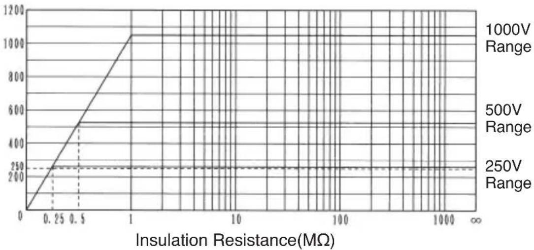
6-4 Output Voltage Characteristics
Output Voltage(V)
line
| Insulation Resistance(MΩ) | 250V Range | 500V Range | 1000V Range | | ------------------------- | ---------- | ---------- | ----------- | | 0.25 | 250 | 500 | 1000 | | 0.5 | 250 | 500 | 1000 | | 1 | 250 | 500 | 1000 | | ∞ | 250 | 500 | 1000 |6-5 Earth Resistance Measurement
The earth resistance function is used to check that equipment is properly earthed to provide appropriate protection against shock hazard to the user or damage to the equipment.
Select the precision or simplified mode, then select the desired measuring range.
Use the optional test leads for precision measurement.

DANGER
- Never touch the tips of the test leads or the circuit under test during earth resistance measurement to avoid possible shock hazard. When the test button is pressed, a voltage of up to 50V AC is present across the terminal E and C, or E and P.
- Keep your fingers and hands behind the protective fingerguard during measurement.
6-6 Precision Measurement (3 POLE)
For precision measurement, use the optional test leads and auxiliary earth spikes.
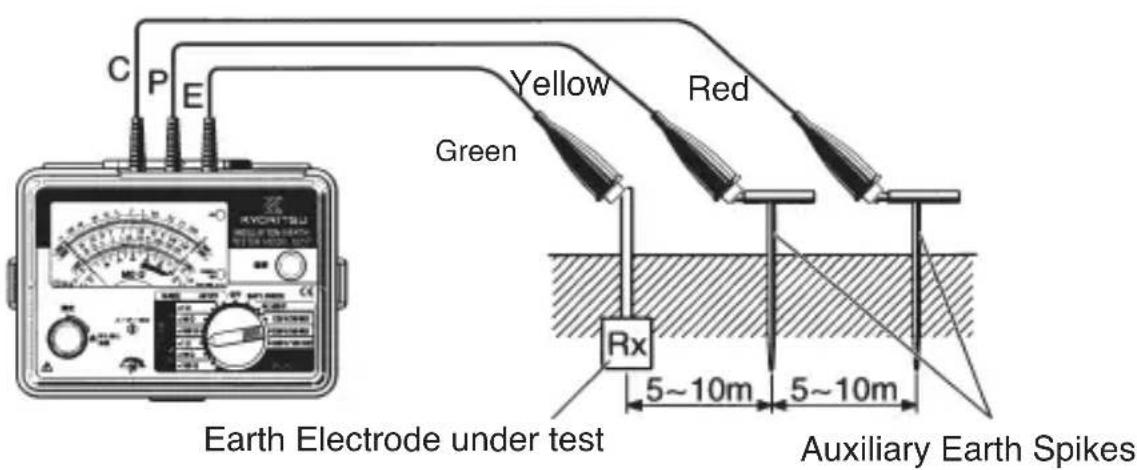
- Slide the sliding shutter over the probe socket to reveal the terminals for precision earth resistance measurement. Insert the plug of each test leads into the appropriate terminal (E: Green lead, P: Yellow lead, C: Red lead).

- Drive auxiliary earth spike P and C deep into the earth as shown in the figure below. They should be aligned at an interval of 5 to 10 meters from the earth electrode under test. Using the alligator clips of the test leads, connect the earth electrode to terminal E, earth spike P to terminal P, and earth spike C to terminal C.
If it is not possible to align the earth electrode and the auxiliary earth spikes, position the earth spikes so that they and the earth electrode form an angle of 100 degrees or greater. This will allow accurate earth resistance measurement.
Make sure to drive the auxiliary earth spikes in the moist part of the earth. Give enough water if the auxiliary earth spikes have to be stuck into dry, stony or sandy part of the earth so that it may become moist.
If it is not possible to drive the auxiliary earth spikes into a hard surface, such as concrete ground, lay the earth spikes there, cover them with a cloth and put water (preferably salt water).
The "OK" lamp lights up when test lead connection to terminals is good and earth resistance at the auxiliary earth spikes is within a limit of tolerance. If it does not illuminate, check the leads for bad connection or lower the auxiliary earth resistance to a proper level. When the instrument is ready to make accurate measurement, the lamp lights up.
- Check Earth Voltage.
Select the "earth voltage 60V AC" range and check whether the reading is 3V or less. When earth voltage is more than 10V, it may result in errors in the reading. To avoid this, reduce the earth voltage, for example, by disconnecting mains from the equipment connected to the earth electrode under test.
- Select the desired precision earth resistance range and press the test button. Multiply the reading by 10 on the x10 range or 100 on the x100 range.
Note:
If test lead connection is bad or lost, the meter goes offscale at a press of the test button. This is not a failure of the instrument. Make correct connection and the instrument will operate properly.
- Set the range selector switch to the OFF position.
CAUTION
- When earth voltage is more than 10V, accurate earth resistance measurement can not be made. Reduce the earth voltage, for example, by detaching the earth electrode from the equipment that it connects to or the disconnecting mains from the equipment.
- When connecting the test leads, make sure that they are separated. If the test leads are twisted or in touch with each other, induction voltage or current may result to affect measurement accuracy.
- For accurate measurement, make sure to drive the auxiliary earth spikes in the moist part of the earth and make good test lead connection.
6-7 Simplified Measurement (2 POLE)
Use the pair of test probes supplied with the instrument for simplified earth resistance measurement. This method is useful when an earth resistance is greater than 10 or when is not possible to drive auxiliary earth spikes into the earth. In this method, an approximate value of earth resistance can be measured by using terminal E and P and, instead of the auxiliary earth spikes, existing earthed equipment that is known to have a low earth resistance. Typical examples are a common earth of mains power supply, an earth electrode of a building, and metal water supply piping.
! DANGER
- When mains power supply is used, be sure to make connection to the earth side of the power supply in order to avoid possible shock hazard.
- Never touch the tips of the test probes or the circuit under test during earth resistance measurement in order to avoid possible shock hazard. When the test button is pressed, a voltage of up to 50V AC is supplied through the probe leads.
-
Keep your fingers and hands behind the protective fingerguard during measurement.
-
Connect the earth probe (alligator clip on black lead) to the earth conductor of an earthed equipment and the line probe (red) to the earth electrode under test.
When making earth resistance measurement using a wall outlet, which is on the secondary side of mains power supply, use a probe with a blade type prod, instead of an alligator clip, as earth probe. (See section 8 "Adapters for Earth Lead and Replacement") Locate earth of the outlet and insert the blade type prod into it.
- Check earth voltage.
Select the "earth voltage AC 60V" range and check whether the reading is 10V or less. When earth voltage is more than 10V, it may result in errors in the reading. To avoid this, reduce the earth voltage, for example, by disconnecting mains from the equipment connected to the earth electrode under test.
- Select the desired simplified earth resistance range and press the test button. Multiply the reading by 10 on the x10 range or 100 on the x100 range.

- Set the range selector switch to the OFF position.
Note:
- When mains power supply that includes a residual current circuit breaker is used for simplified measurement, the circuit breaker does not trip since test current is as low as about 2mA.
- As only two terminals of the instrument are used in simplified measurement, earth resistance "R _E " of the earthed electrode connecting to terminal P will necessarily be added to true earth resistance value "Rx":
Reading = Rx + R_E
If " R_E " is known, obtain a true earth resistance value by subtracting " R_E " from the reading.
- In the simplified earth resistance measurement (method of using two terminals), the reading includes the resistance of the test probes, which may be significant on the x 1Ω range. For more accurate measurement, the resistance of the test probes should be subtracted from the reading. To measure this resistance, short the test probes together and press the test button to take the reading.
7. Test Prods for Line Probe and Replacement
1. Types of test prods
Model 8256: Standard Test Prod (Mold)
Used in ordinary situations. (This type of prod is fitted to the line probe at the time of shipment.)
Model 8072: Standard Test Prod
Used in ordinary situations.
Model 8017: Extension Prod
Used in difficult-to-reach situations.
Model 8016: Pickel Prod (Optional):
Used to hook the line probe on a conductor.
2. How to Replace Prod
To remove the test prod, turn the cap of the line probe counter clockwise.
Insert the threaded end of another type of prod into the hexagonal hole on the probe cap as shown. Then, turn the probe cap clockwise to secure it onto the probe body.

8. Adapters for Earth Lead and Replacement
1. Types of earth lead adapters
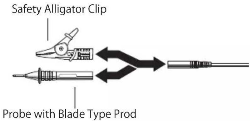
Model 7131B: Safety Alligator Clip
Used to connect to an earth terminal, including an earth terminal board.
Model 7161A: Flat test prod
Used to connect to earth of a mains wall outlet.
2. How to exchange earth lead adapter
Pull the adapter to remove it from the plug of the earth lead. Insert another type of adapter fully into the plug of the earth lead.
9. Optional Accessories
Model 7100A Test Lead Set for Precision Earth Resistance Measurement (includes Test Leads, Carrying Case, Cord Reels, Auxiliary Earth Spikes)
natural_image
Illustration of three circular mechanical components with a central knob, no text or symbols present

natural_image
Line drawing of a wooden box labeled 'KYOYITSU' with handle and side tabs (no additional text or symbols)MODEL 7095A+MODEL 8200 MODEL 8032 MODEL 9091A
Model 8016 Pickel Prod
Model 7095A Earth Resistance Test Leads
Model 8032 Auxiliary Earth Spikes (Two pieces)
Model 8200 Cord Reels
Model 9091A Carrying Case for Cord Reels
Model 7115 extension probe
9-1 How to Use Test Leads and Cord Reels
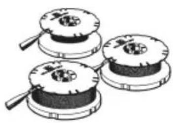
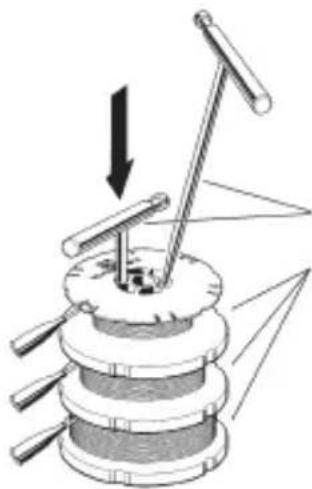
Handling and storing earth test leads is always troublesome for the user. However, using the optional cord reels helps to eliminate this problem.
As shown below, test leads can easily be rewound on reels by inserting an auxiliary earth spike into a lead-rewind hole and turning it. This also helps to avoid twists or other kinds of damage to extend the test leads' useful life.
natural_image
Mechanical device with lever mechanism and directional arrows indicating motion (no text or symbols)Auxiliary Earth Spike
Cord Reels
10. Cleaning Meter Cover
Do not try to remove dirt on the meter cover by rubbing hard with a dry cloth. This can remove anti-electrostatic agent applied to the surface of the meter cover.
When the meter reading is affected by electrostatic build up on the meter cover, wipe the meter cover surface using a cloth dampened with off-the-shelf anti-static agent or detergent. To avoid possible deforming or discoloring, do not use solvents.
To clean the body of the instrument, use cloth dampened with detergent.
CAUTION
- Never use paint thinner, benzene or other solutions containing solvents for cleaning the instrument. Otherwise, deforming or discoloring of the instrument body or the meter cover may result.
Note:
- Handle the instrument with care and follow the instructions in order to maintain it in good condition for a long period of time.
11. Before Sending for Repair
Use the following troubleshooting guide for hints on problems with instrument operation.
| Condition Possible Cause | |
| The meter does deflect in BATT CHECK. | Check batteries are installed correctly. |
| "Power-on" indication LED does not light up when the test button is pressed on insulation resistance ranges | Check batteries are installed correctly, or check the test probe connector is correctly inserted into the probe socket. |
| "Power-on" indication LED does not light up on AC voltage range. | This is not a failure. |
| BATT CHECK results in "OK", but the meter does not read on any range | Check test leads for a break and replace them if necessary. |
| On earth voltage ranges, "Power-on" indication LED lights up before the test lead connection is made. | This is not a failure, but it is notifying the user that the function selector switch remains set to the earth voltage range. |
| On earth resistance ranges, "Power-on" indication LED lights up and the meter goes offscale at a press of a button when the probe connector is not plugged into the socket. | This is not a failure. The instrument will operate properly after making correct test lead connection. |
| On earth resistance ranges, "OK" lamp does not light up | Check the test leads are correctly connected to the instrument or to the auxiliary earth bars.Check the auxiliary earth bars are stuck into a moist part of the earth. If not, give enough water.Check the test leads for a break and replace them if necessary. |
When using the instrument, always check whether;
- The test probe connector is correctly plugged into the probe socket.
● The batteries are correctly installed.
● The batteries have enough power. - The test leads for precision earth resistance measurement are correctly connected to the instrument's terminals.
● There is no break in test leads or test probes.

CAUTION
- The instrument passed inspections and shipped in the best possible condition. If any abnormal operations are noted because of aging, do not use the instrument and return it for inspection and repair.
MEMO
DISTRIBUTOR
Kyoritsu reserves the rights to change specifications or designs described in this manual without notice and without obligations.

natural_image
Abstract black arrow symbol pointing left within a rectangular frame (no text or numbers)Factory: Ehime, Japan
www.kew-ltd.co.jp
- Safety Warnings
- WARNING
- ! DANGER
- CAUTION
- Features
- Specifications
- 3-1 Standards
- 3-2 Insulation Resistance Ranges and Accuracy
- 3-7 Battery Life
- 3-8 General Specifications
- Instrument Layout
- Preparation for Measurement
- 5-1 Installing Batteries
- Note:
- 5-2 Mechanical Zero Adjustment
- 5-3 Connecting Test Leads
- DANGER
- 5-4 Battery Voltage Check
- 5-5 "Power-on" Indication LED
- 5-6 Scale Illumination Function
- 5-7 Attaching Neck Strap
- 5-8 Fitting Case Lid Under Case
- Measurement
- 6-1 AC Voltage Measurement (Mains Disconnection Check)
- 6-2 Insulation Resistance Measurement
- 6-3 Continuous Insulation Resistance Measurement
- 6-4 Output Voltage Characteristics
- 6-5 Earth Resistance Measurement
- 6-6 Precision Measurement (3 POLE)
- 6-7 Simplified Measurement (2 POLE)
- Test Prods for Line Probe and Replacement
- Types of test prods
- How to Replace Prod
- Adapters for Earth Lead and Replacement
- Types of earth lead adapters
- How to exchange earth lead adapter
- Optional Accessories
- 9-1 How to Use Test Leads and Cord Reels
- Cleaning Meter Cover
- Before Sending for Repair
- MEMO
Brand : Kyoritsu
Model : 6018
Category : Multimeter