
KEW 2413R - Multimeter Kyoritsu - Free user manual and instructions
Find the device manual for free KEW 2413R Kyoritsu in PDF.


| Product Type | Digital Clamp Meter (AC Leakage/Current) |
| Model | KEW 2413R |
| Brand | Kyoritsu |
| Dimensions | 250 mm (L) x 130 mm (W) x 50 mm (D) |
| Weight | Approx. 600 g (including battery) |
| Power Supply | One 9V battery (6F22 or equivalent) |
| Display | 3 1/2 digit LCD, max count 1999, with backlight |
| AC Current Ranges | 200mA, 2A, 20A, 200A, 1000A |
| Maximum Conductor Size | Approx. 68 mm diameter |
| Safety Rating | CAT III, 300V AC, Pollution Degree 2 |
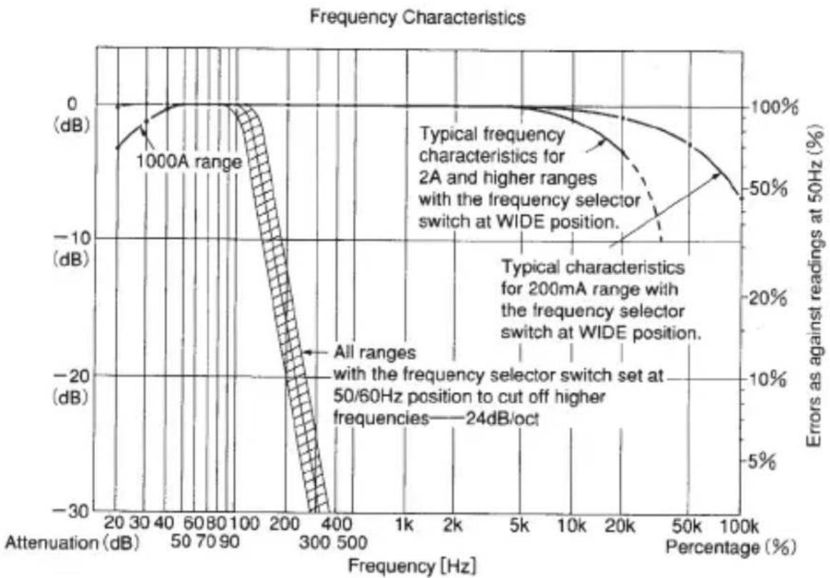
| Frequency Response | 40 Hz - 1 kHz (WIDE), 40-100 Hz (50/60 Hz filter) |
| Peak Hold Function | Selectable 10 ms or 100 ms response time |
| Data Hold | Freezes display reading on all ranges |
| Analogue Output | AC and DC voltage output via optional Model 7073 cord |
| Low Pass Filter | Approx. 100 Hz cutoff, -24 dB/octave attenuation |
| Operating Temperature/Humidity | 0 to 40°C, up to 85% RH (non-condensing) |
| Storage Temperature/Humidity | -20 to 60°C, up to 80% RH |
| Standards | IEC 61010-1, IEC 61010-2-032, IEC 61326-1, EU RoHS |
| Included Accessories | 6F22 battery, carrying case, instruction manual |
| Cleaning | Use damp cloth with mild detergent; avoid solvents |
| Battery Replacement | When 'BATT' symbol appears; remove during replacement |
Frequently Asked Questions - KEW 2413R Kyoritsu
User questions about KEW 2413R Kyoritsu
0 question about this device. Answer the ones you know or ask your own.
Ask a new question about this device
Download the instructions for your Multimeter in PDF format for free! Find your manual KEW 2413R - Kyoritsu and take your electronic device back in hand. On this page are published all the documents necessary for the use of your device. KEW 2413R by Kyoritsu.
USER MANUAL KEW 2413R Kyoritsu
- Safety Warnings 1
- Features 4
- Specifications 5
- Instrument Layout 9
- Operation
5 - 1 Preparation ...... 11
5-2 AC Current Measurement 11
5 - 3 How to Use Peak Hold Function ……14
5 - 4 How to Use The Frequency Selector Switch ……16
5 - 5 How to Use Data Hold Function ……17
5 - 6 How to use Back Light ......17
5 - 7 Analogue Output How to Use Model 7073 Output Cord ……18 - Battery Replacement 19
- Cleaning 20
- Before Sending For Repair 21
1. Safety Warnings
This instrument has been designed and tested according to IEC Publication 61010: Safety Requirements for Electronic Measuring Apparatus. This instruction manual contains warnings and safety rules which must be observed by the user to ensure safe operation of the instrument and retain it in safe condition. Therefore, read through these operating instructions before starting using the instrument.
- Thesymbol ⚠️ indicated on the instrument means that the user must refer to related parts in the manual for safe operation of the instrument. Be sure to carefully read the instruction following each ⚠️ symbol in this manual.

DANGER
is reserved for conditions and actions that are likely to cause serious or fatal injury.

WARNING
is reserved for conditions and actions that can cause serious or fatal injury.

CAUTION
is reserved for conditions and actions that can cause bodily injury or instrument damage.

WARNING
- Read through and understand instructions contained in this manual before starting using the instrument.
- Save and keep the manual handy to enable quick reference whenever necessary.
● The instrument is to be used only in its intended applications.
● Understand and follow all the safety instructions contained in the manual.
Failure to follow the instructions may cause injury, instrument damage and/or damage to equipment under test. Kyoritsu is by no means liable for any damage resulting from the instrument in contradiction to this cautionary note.
Following symbols are used on the instrument and in the instruction manual. Attention should be paid to each symbol to ensure your safety.
Refer to the instructions in the manual.
This symbol is marked where the user must refer to the instruction manual so as not to cause personal injury or instrument damage.
☐ Indicates an instrument with double or reinforced insulation.
Indicates that this instrument can clamp on bare conductors when measuring a voltage corresponding to the applicable Measurement category, which is marked next to this symbol.
This instrument satisfies the marking requirement defined in the WEEE Directive (2002/96/EC). This symbol indicates separate collection for electrical and electronic equipment.
⚠️ DANGER
● Never make measurement on a circuit above 300V AC (CAT. III)
- Do not attempt to make measurement in the presence of flammable gasses, fumes, vapor or dust. Otherwise, the use of the instrument may cause sparking, which can lead to an explosion.
● Transformer jaw tips are designed not to short the circuit under test. If equipment under test has exposed conductive parts, however, extra precaution should be taken to minimize the possibility of shorting.
● Never open the battery compartment cover when making measurement.
● Never attempt to use the instrument if its surface or your hand is wet.
- Do not exceed the maximum allowable input of any measurement range.
● Never try to make measurement if any abnormal conditions, such as broken Transformer jaws or case is noted.
The instrument is be used only in its intended applications or conditions. Otherwise, Safety functions equipped with the instrument doesn't work, and instrument damage or serious personal injury may be caused.
- Keep your fingers and hands behind the barrier during measurement.
WARNING
● Never attempt to make any measurement if any abnormal conditions are noted, such as broken case, cracked test leads and exposed metal parts.
- Do not install substitute parts or make any modification to the instrument. Return the instrument to Kyoritsu or your distributor for repair or re-calibration.
- Do not try to replace the battery if the surface of the instrument is wet.

CAUTION
- Do not expose the instrument to the direct sun, extreme temperatures or dew fall.
-
Be sure to set the function selector switch to the “OFF” position after use. When the instrument will not be used for a long period of time, place it in storage after removing the battery.
This is to avoid damage to the instrument by possible leakage from the battery. -
Use a damp cloth and detergent for cleaning the instrument. Do not use abrasives or solvents.
● This instrument isn't dust & water proofed. Keep away from dust and water.
● Never apply voltage to the OUTPUT terminal. the terminal is not electrically isolated from the internal circuits of the instrument.
Measurement categories (Over-voltage categories)
To ensure safe operation of measuring instruments, IEC 61010 establishes safety standards for various electrical environments, categorized as O to CAT IV, and called measurement categories.
Higher-numbered categories correspond to electrical environments with greater momentary energy, so a measuring instrument designed for CAT III environments can endure greater momentary energy than one designed for CAT II.
O : Circuits which are not directly connected to the mains power supply.
CAT II : Primary electrical circuits of equipment connected to an AC electrical outlet by a power cord.
CAT III : Primary electrical circuits of the equipment connected directly to the distribution panel, and feeders from the distribution panel to outlets.
CAT IV : The circuit from the service drop to the service entrance, and to the power meter and primary overcurrent protection device (distribution panel).

2. Features
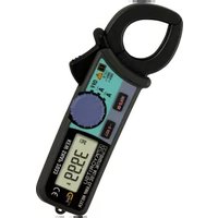
KEW 2413R is a unique digital clamp meter for both very low current and high current measurements. Its shielded transformers jaws minimizes the effect of external stray magnetic field, enabling leakage current measurements.
● Measures from 0.1mA to 1000A AC and provides frequency response higher than 1kHz on all measuring ranges.
Measurements also possible with approximately -7% accuracy at 20 kHz on 200mA range.
- Provides a frequency selector switch — 50/60Hz or WIDE — to turn on or off an incorporated low pass filter. This permits current measurement in mains fundamental frequency only or a wide range of frequencies, including those from such devices as inverters.
● Peak-hold facility with selectable response time of 10ms or 100 ms.
● Two-way analogue output terminal
Provides AC voltage output proportional to the current under test for monitoring the waveform with an oscilloscope.
Also convent AC current readings to DC voltage output for direct connection to such devices as a chart recorder.
● Data hold function to allow for easy readings in hard-to-reach locations. Display can be observed away from the conductor.
● LCD Back Light function to facilitate working at dimly lit situations.
3. Specifications
Measuring Ranges and Accuracy
● AC Current
| Ranges | Accuracy | Time Limit for Measurements | ||
| Frequency Range Response | ||||
| WIDE* Add 2% at CF ≥ 2 | 50/60Hz* only sine wave | |||
| 200mA | 0~199.9mACF≤3.0 | ±1.8%rdg±5dgt (50/60Hz)±3.0%rdg±5dgt (40~1kHz) | Continuous | |
| 2A | 0~1.999ACF≤3.0 | |||
| 20A | 0~19.99ACF≤3.0 | |||
| 200A | 0~199.9ACF≤3.0 | ±2.0%rdg±5dgt (50/60Hz)±3.5%rdg±5dgt (40~1kHz) | ±3.0%rdg±5dgt | |
| 1000A | 0~500ACF≤3.0 | |||
| 501~1000ACF≤3.0 | ±5.0%rdg (50/60Hz) | ±5.5% rdg | 10min. | |
● Effective Value (RMS)
Most alternating currents and voltages are expressed in effective values, which are also referred to as RMS (Root-Mean-Square) values. The effective value is the square root of the average of square of alternating current or voltage values. Many clamp meters using a conventional rectifying circuit have "RMS" scales for AC measurement. The scales are, however, actually calibrated in terms of the effective value of a sine wave though the clamp meter is responding to the average value. The calibration is done with a conversion factor of 1.111 for sine wave, which is found by dividing the effective value by the average value. These instruments are therefore in error if the input voltage or current has some other shape than sine wave.
CF (Crest Factor) is found by dividing the peak value by the effective value.
Examples: Sine wave: CF=1.414
Square wave with a 1:9 duty ratio: CF=3
Reference
| Waveform | Effective value Vrms | Average value Vavg | Conversion factor Vrms/ Vavg | Reading errors for average sensing instrument | Crest factor CF |
 |  ÷0.707 ÷0.707 |  ÷0.637 ÷0.637 |  ÷1.111 ÷1.111 | 0% | 2 ÷1.414 |
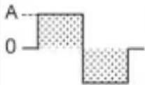 |  D D |  D D |  , , | × 1.111 - AA × 100 = 11.1% | 1 |
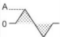 |  | 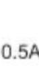 |  ÷1.155 ÷1.155 | 0.5A × 1.111 - 33 × 100 = -3.8% | 3 ÷1.732 |
 D=f/T D=f/T |  AVD AVD |  A = n · D A = n · D |  - 1 - 1 | (1.111 - 1) × 100% | = 1 |
line
| Frequency Range | Attenuation (dB) | Percentage (%) | | --------------- | ---------------- | -------------- | | 1000A range | ~30 | ~50 | | 200A range | ~40 | ~70 | | 200A range | ~50 | ~80 | | 200A range | ~60 | ~90 | | 200A range | ~70 | ~100 | | 200A range | ~80 | ~110 | | 200A range | ~90 | ~120 | | 200A range | ~100 | ~130 | | 200A range | ~110 | ~140 | | 200A range | ~120 | ~150 | | 200A range | ~130 | ~160 | | 200A range | ~140 | ~170 | | 200A range | ~150 | ~180 | | 200A range | ~160 | ~190 | | 200A range | ~170 | ~200 | | 200A range | ~180 | ~210 | | 200A range | ~190 | ~220 | | 200A range | ~200 | ~230 | | 200A range | ~210 | ~240 | | 200A range | ~220 | ~250 | | 200A range | ~230 | ~260 | | 200A range | ~240 | ~270 | | 200A range | ~250 | ~280 | | 200A range | ~260 | ~290 | | 200A range | ~270 | ~300 | | 200A range | ~280 | ~310 | | 200A range | ~290 | ~320 | | 200A range | ~300 | ~330 | | 2A and higher ranges (Typical) | - | - | | Typical frequency characteristics | - | - | | Typical frequency characteristics | - | - | | Typical frequency characteristics | - | - | | Typical frequency characteristics | - | - | | Typical frequency characteristics | - | - | | Typical frequency characteristics | - | - | | Typical frequency characteristics | - | - | | Typical frequency characteristics | - | - | | Typical frequency characteristics | - = All ranges with the frequency selector switch set at 50/60Hz position to cut off higher frequencies — 24dB/oct — | - | | Typical frequency characteristics | - = Typical ranges with the frequency selector switch set at 50/60Hz position to cut off higher frequencies — 24dB/oct — | - | | Typical frequency characteristics | - = Typical ranges with the frequency selector switch set at 50/60Hz position to cut off higher frequencies — 24dB/oct — | - | | Typical frequency characteristics | - = Typical ranges with the frequency selector switch set at 5/6/Hz position to cut off higher frequencies — 24dB/oct — | - | | Typical frequency characteristics | - = Typical ranges with the frequency selector switch set at 5/6/Hz position to cut off higher frequencies — 24dB/oct — | - | | Typical frequency characteristics | - = Typical ranges with the frequency selector switch set at 5/6/Hz position to cut off higher frequencies — 24dB/oct — (Note: this is estimated based on the percentage scale). | - | | Typical frequency characteristics | - = Typical ranges with the frequency selector switch set at 5/6/Hz position to cut off higher frequencies — 24dB/oct — (Note: The data is estimated based on the percentage scale). | - | | Typical frequency characteristics | - = Typical ranges with the frequency selector switch set at 5/6/Hz position to cut off higher frequencies — 24dB/oct — (Note: The data is estimated based on the percentage scale). | - | | Typical frequency characteristics | - = Typical ranges with the frequency selector switch set at 5/6/Hz position to cut off higher frequencies— 24dB/oct — (Note: The data is estimated based on the percentage scale). | - | | Typical frequency characteristics | - = Typical ranges with the frequency selector switch set at 5/6/Hz position to cut off higher frequencies— 24dB/oct — (Note: The data is estimated based on the percentage scale). | - | | Typical frequency characteristics | - = Typical ranges with the frequency selector switch set at WIDE position, cut off higher frequencies — 24dB/oct — (Note: The data is estimated based on the percentage scale). | - | | Typical frequency characteristics | - = Typical ranges with the frequency selector switch set at WIDE position, cut off higher frequencies — 24dB/oct — (Note: The data is estimated based on the percentage scale). | - | | Typical frequency characteristics | - = Typical ranges with the frequency selector switch set at WIDE position, Cut off higher frequencies — 24dB/oct — (Note: The data is estimated based on the percentage scale). | - | | Typical frequency characteristics | - = Typical ranges with the frequency selector switch set at WIDE position, Cut off higher frequencies — 24dB/oct — (Note: The data is estimated based on the percentage scale). | - | | Typical frequency characteristics | - = Typical ranges with the frequency selector switch set at 5/6/Hz position, Cut off higher frequencies — 24dB/oct — (Note: The data is estimated based on the percentage scale). | - | | Typical frequency characteristics | - = Typical ranges with the frequency selector switch set at 5/6/Hz position, Cut off higher frequencies — 24dB/oct — (Note: The data is estimated based on the percentage scale). | - | | Typical frequency characteristics | - = Typical ranges | | | Typical frequency characteristics | - nan | | | Typical frequency characteristics | - nan | | | Typical frequency characteristics | - nan | | | Typical frequency characteristics | - nan | | | Typical frequency characteristics | - nan | | | Typical frequency characteristics | - nan | | | Typical frequency characteristics | - nan | | | Typical frequency characteristics | - nan | | | Typical frequency characteristics (Note: The data is estimated based on the percentage scale.) | - nan | | | Typical frequency characteristics (Note: The data is estimated based on the percentage scale.) | - nan | | | Typical frequency characteristics (Note: The data is estimated based on the percentage scale.) | - nan | | | Typical frequency characteristics (Note: The data is estimated based on the percentage scale.) | - nan | | | Typical frequency characteristics (Note: The data is estimated based on the percentage scale.) | - nan | |Fig. 1
Analogue Output (Output impedance: Approx. 1k Ω)
● AC Output
| Range | Measuring Range | AC Output Voltage | Accuracy |
| 200mA | 0~200mA | 0~200mV | ±2.0%rdg±0.5mV |
| 2A | 0~2A | ||
| 20A | 0~20A | ||
| 200A | 0~200A | ±2.5%rdg±0.5mV | |
| 1000A | 0~500A | 0~50mV | ±3.0%rdg±0.5mV |
| 501A~1000A | 50~100mV | ±5.0%rdg±0.5mV |
*Voltage proportional to the current under test is output with "WIDE" frequency characteristics regardless of the setting of the frequency Selector or peak hold switch.
● DC Output
| Ranges | AC Input Current | DC Output Voltage | Accuracy (Frequency Range) | |
| Freq. Selector Switch at WIDE position | Freq. Selector Switch at 50/60Hz position | |||
| 200mA | 0~200mA | 0~200mV | ±3.0%rdg±0.5mV | ±3.5%rdg ±0.5mV |
| 2A | 0~2A | |||
| 20A | 0~20A | |||
| 200A | 0~200A | ±3.5%rdg±0.5mV | ±4.0%rdg ±0.5mV | |
| 1000A | 0~500A | 0~50mV | ±5.0%rdg±0.5mV | ±5.5%rdg ±0.5mV |
| 501A~1000A | 50~100mV | ±7.0%rdg±0.5mV | ±7.5%rdg ±0.5mV | |
* DC voltage is output in proportion to the display reading, which reflects frequency selector or peak hold switch position — 200mV DC for 2000 count reading.
Operating System : Dual Integration
Display
: Field effect 3·1/2 digit liquid crystal display with maximum count of 1999
Range selection : Manual
Overrange Indication
: “1” is displayed on the highest digit except for 1000A AC range.
Response Time : Approx. 3 seconds
Sample Rate :
Approx. 3 times per second
Data Hold
: Available on all ranges
Location for use : Indoor use, Altitude up to 2000m
Temperature & Humidity for Specified Accuracy
Storage Temperature & Humidity
Operating Temperature & Humidity
Power Source
Low Battery Warning :
Current Consumption
Standard(Safety)
(EMC)
Environmental Standards
Overload Protection
Withstand Voltage
Insulation Resistance
Conductor Size
Dimensions/Weight
Accessories
Optional Accessories
Peak Hold
: 23°C± 5 °C , relative humidity up to 85% without condensation
:-20\~60°C, relative humidity up to 80% without condensation
: 0 \~ 40°C ,relative humidity up to 85% without condensation
: One 6 F22 or equivalent battery
“BATT” symbol is shown on the display.
: Approx. 5mA max.(use Back Light:8mA max.)
: IEC61010-1
IEC61010-2-032
CAT III ,AC300V,Pollution degree 2
: IEC61326-1
: EU RoHS Directive compliant
: 1500AAC max for 1 minute
: 3470V AC for 5 seconds between electrical circuit and housing cases
: 50M Ω or greater at 1000V between electrical circuits and housing cases or metal parts of jaws
: Approx. 68mm diameter max.
: 250(L)× 130(W)× 50(D)mm.
Approx. 600g (including battery)
: 6F22 battery
Carrying case Instruction manual
: Model 7073 two-way output cord
: Response time selectable from approx. 10ms and 100ms.
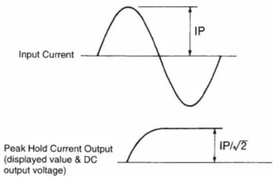
1/√ 2 of the peak current is displayed, which means an RMS reading will be obtained when current having sinusoidal waveform in measured.
Peak hold reading varies by approximately ± 1% max of full scale in the first minute at 23°C± 5°C and relative humidity of 75% without condensation.
4. Instrument Layout
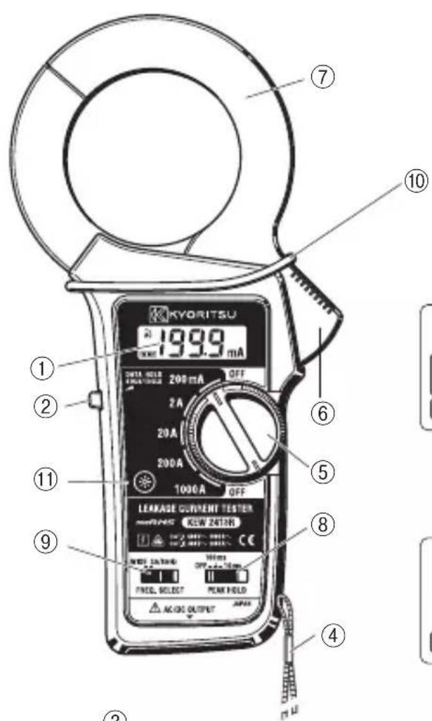

LCD

over range indication

Fig.2
① LCD
Field effect liquid crystal display with maximum indication of 1999. Function symbol(mA, A) and decimal point automatically appear as the function / range switch is turned.
“-BATT” is displayed on the lower right side for low battery warning and “1” is displayed only at the highest digit for overrange indication.
② Data Hold Button
Allows for easy reading in dimly lit or hard-to-reach-locations. The display can be observed away from the conductor after pushing in the button. Data hold can be released by pushing the button again after the reading is taken. Symbol “H” is displayed on the LCD.
③ Two-way Analogue Output Terminal
AC current picked up by transformer jaws ⑦ is converted and output as AC and DC voltage output. (See Analogue Output in section 3, Specifications.) Insert output cord Model 7073 into this terminal for monitoring waveform with an oscilloscope or connecting to a recorder.
④ Safety Hand Strap
Prevents the instrument from slipping off the hand during use.
⑤ Power Function/Range Switch
Selection function and range. It is also used to turn power on or off.

CAUTION
Always set the Power Function/Range Switch to the OFF position after use.
⑥ Jaw Trigger
Operates transformer jaws ⑦. Press to open the jaws.
⑦ Transformer Jaws
Pick up the current flowing through the conductor.
⑧ Peak Hold Selector Switch
Selects 10ms or 100ms response time. Symbol 📄” is displayed on the LCD. Set the switch back to the OFF position to release peak hold or make normal measurements.
⑨ Frequency Selector Switch
Makes frequency response selection. Symbol "WIDE" or "60/60HS" displayed on the LCD.
⑩ Barrier
It is a part providing against electrical shock and ensuring the minimum required air and creepage distances.
⑪ Back Light Button
When the “Back Light Button” is pressed, the LCD back light will be on.
It will be automatically off after about 10 seconds.
5. Operation
5 - 1 Preparation
(1) To Check battery set the function/range switch ⑤ To the desired position. If the display is clear without symbol “BATT” owing, battery voltage is sufficient. If the display blanks or “BATT” is indicated, replace the battery in accordance with the battery replacement procedures as described in section 6.
Note: “BATT” also appears on the display when the battery becomes exhausted during use. Replace with a new battery.
(2) Make certain that the data hold button is in the off position — not pressed down. If a measurement is made with the data hold button pressed in, the display remains locked irrespective of input. Symbol “H” is displayed on the LCD.
5-2 AC current Measurement

WARNING
- Do not make measurement on a circuit above 300V AC (CAT III).
- Transformer jaw tips are designed not to short the circuit under test. If equipment under test has exposed conductive parts, however, extra precaution should be taken to minimize the possibility of shorting.
- Do not make measurement with the battery compartment cover removed from the instrument.
- Keep your fingers and hands behind the barrier during measurement.

CAUTION
- Transformers jaws, especially their tips, have been precisely adjusted to obtain maximum accuracy. Take sufficient care to avoid shock, vibration or excessive force when handing the instrument.
- When a foreign substance is stick in the jaw tips or they cannot properly engage, the transformer jaws do not fully close. In such a case, do not release the jaw trigger suddenly or attempt to close the transformer jaws by applying external force. Make sure that the jaws close by themselves after removing the foreign substance or making them free to move.
● The maximum size of conductor that can be measured is approx. 68mm in diameter. An accurate measurement cannot be made on a conductor larger than this, because the transformer jaws cannot be fully closed. - Frequency selector switch ⑨ is designed to select the “50/60Hz” and “WIDE” frequency ranges. For further details, refer to section 5-4 for operation of the frequency selector switch.
● The transformer jaws may buzz when measuring large current. This has no effect on the instrument's performance or safety.
(1) Set the function/range switch to the desired position. Do not exceed the maximum allowable input current for the selected range.
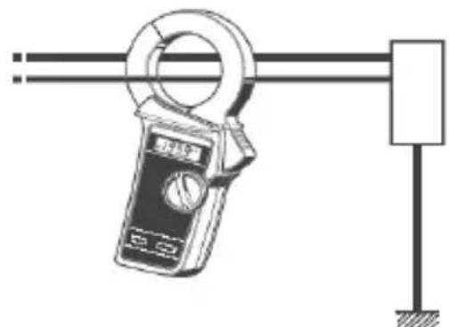
(2) For normal measurement, press the jaw trigger to open the transformer jaws and clamp onto one conductor only. See Fig.3. Earth leakage current or small current that flow through a grounded wire can also be measured by this method. (Fig. 4)
(3) To measure out of balance leakage current, clamp onto all conductors except a grounded wire. The leakage current measure will be indication on the display. (Fig.5)
natural_image
Simple line drawing of a handheld electrical meter connected to a vertical pole (no text or symbols)Fig.3 Normal AC Current Measurements

natural_image
Technical line drawing of a mechanical clamp device with a hanging weight and base (no text or symbols)Fig.4 Earth Leakage Current Measurements


3-phase 3-wire system. (in 4-wire system with neutral clamp onto all 4 wire)
Fig.5 Measurements out of balance Leakage
Note : When measuring large current, observe the time limit specified in section 3, Specifications. Otherwise, the transformers jaws may overheat, resulting in damage to the instrument.
It may take several tens of seconds to indicate exact zero, but this is normal.
Even if current is being applied to the instrument till zero is indicated on the LCD, it doesn't affect the readings.
5-3 How to Use Peak Hold Function
10ms or 100ms response time can be selected for peak hold measurement. Make selection according to your application needs.
(1) With the transformer jaws clamped onto the conductor under test, slide the peak hold switch from the OFF position to the desired peak response time position. Symbol “P” is displayed on the LCD.
(2) The peak hold display reads 1 / 2 of the peak current value. Therefore, an RMS reading will be obtained when the current under test has a sinusoidal waveform.
line
| Input Current | Peak Hold Current Output (IP/√2) | | ------------- | -------------------------------- | | - | - | | + | IP/√2 |Fig. 6
(3) Slide the peak hold switch back to the OFF position for a reset.
Note 1: KEW 2413R uses an analogue peak hold circuit to ensure a quick response to input current. Because of the nature of this circuit, the peak hold reading may gradually fall or, in a rare case, rise with time. This is likely to be apparent when the instrument is used in a high temperature and high humidity environment. Therefore, the instrument will not be suitable for making peak measurement over an extended period of time. In case of such a need, connect a recorder to the instrument via the analogue output terminal.
Note 2 : If it is necessary to read the display away from the conductor in a peak hold measurement, press the data hold switch ② first and then remove the instrument from the conductor. Otherwise, the peak hold reading may be higher than the actual value due to the electrical noise caused by the opening and closing of the transformer jaws. Press the data hold switch again for a reset.
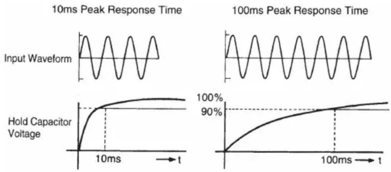
(4) Difference between 10ms and 100ms Peak Response Time The peak hold circuit in this instrument charges the peak-hold capacitor after rectifying the input waveform. The time for the voltage of the capacitor to reach its peak value varies according to its capacitance and the output impedance of the charging circuit. KEW 2413R sets the time for the voltage of the capacitor to reach 90% of its peak value to 10ms or 100ms by switching between two output impedances. Refer to Figure 7 for further details.
line
| Time (ms) | Peak Response Time (10ms) | Peak Response Time (100ms) | Hold Capacitor Voltage | |-----------|----------------------------|-----------------------------|------------------------| | 0 | 0 | 0 | 0 | | 10 | ~1.5 | ~1.5 | ~100% | | 20 | ~1.5 | ~1.5 | ~90% | | 30 | ~1.5 | ~1.5 | ~85% | | 40 | ~1.5 | ~1.5 | ~80% | | 50 | ~1.5 | ~1.5 | ~75% | | 60 | ~1.5 | ~1.5 | ~70% | | 70 | ~1.5 | ~1.5 | ~65% | | 80 | ~1.5 | ~1.5 | ~60% | | 90 | ~1.5 | ~1.5 | ~55% | | 100 | ~1.5 | ~1.5 | ~50% | | 110 | ~1.5 | ~1.5 | ~45% | | 120 | ~1.5 | ~1.5 | ~40% | | 130 | ~1.5 | ~1.5 | ~35% | | 140 | ~1.5 | ~1.5 | ~30% | | 150 | ~1.5 | ~1.5 | ~25% | | 160 | ~1.5 | ~1.5 | ~20% | | 170 | ~1.5 | ~1.5 | ~15% | | 180 | ~1.5 | ~1.5 | ~10% | | 190 | ~1.5 | ~1.5 | ~5% | | 200 | ~1.5 | ~1.5 | ~0% |Fig.7
For instance, select the 10ms response time when measuring a surge current that will occur when a power supply device is switched on. The 100ms response time is recommended for measuring the starting current of a motor or similar equipment. A stable measurement can be made on the 100ms second response time setting as the peak hold circuit does not readily respond to the surge current.
Note 3 : The peak hold circuit of this instrument may not capture some signals depending on phases because a half-wave rectifier circuit is used.
Response characteristics are 10ms/ 100ms. Noises on higher frequencies caused by inverters may not be captured. Readings with Peak Hold off might become smaller or zero when activating the Peak hold function, but this is not a malfunction.
5-4 How to Use The Frequency Selector Switch
KEW 2413R has a very good frequency response because of the electromagnetic property of its transformers jaws. Therefore, it measured, AC current not only of fundamental frequency of 50Hz or 60Hz, but of high frequencies and harmonics superimposed on the fundamental frequency. To eliminate these superimposed components and measure only in the fundamental frequency, KEW 2413R has a Low pass filter circuit, which can be activated by setting the frequency selector switch to the “50/60Hz” position. When the frequency selector switch is set to “WIDE”, symbol “WIDE” is displayed on the LCD. When the switch is set to “50/60Hz”, symbol “50/60Hz” is displayed on the LCD.
The Low pass filter has a cut-off frequency of approx. 100Hz and an attenuation characteristics of approx. -24 dB/octave.
Note : -24dB/octave means that the magnitude of a signal declines by a factor of 16 when its initial frequency doubles.
The frequency selector switch has the following two positions.
● WIDE(40Hz — over 1kHz):
Covers a wide frequency band from mains supply to high frequencies generated by such equipment as inverters.
● 50/60Hz(40 — Approx.100Hz):
Filters out high frequency components to restrict measurement in mains frequency band.
Note : Selection with the frequency selector switch dose not apply to AC output of the two-way analogue output. DC output of the two-way analogue output reflects the frequency selector switch setting. Refer to Figure. 1 for frequency characteristics.
5-5 How to Use Data Hold Function
Push in the Data Hold button to freeze the reading. This is especially useful for taking a reading in a dimly lit or hard-to-reach locations. The display can be observed away from the conductor. Symbol “H” is displayed on the LCD. Push the button again to release the reading.
5-6 How to use Back Light
When the “Back Light Button” is pressed, the LCD back light will be on. It will be automatically off after about 10 seconds.
5-7 Analogue Output: How to Use Model 7073 Output Cord AC and DC output can be obtained by inserting optional Model 7073 output cord into the two-way analogue output terminal ③.
AC Output:
Can be monitored by connecting a digital multimeter to analogue output terminal or observed as a waveform by connecting an oscilloscope.
DC Output:
Can be monitored by connecting a digital multimeter, or a recorder, which enables many hours of monitoring. See Figure 8. With the 2413R in the peak hold mode, DC voltage corresponding to 1/2 of a peak current value can be held and output.
Refer to section 5-3, How to Use Peak Hold Function.

flowchart
graph TD
    A["KEW 2413R"] --> B["Oscilloscope"]
    B --> C["AC Output"]
    C --> D["Multimeter"]
    D --> E["DC Output"]
    E --> F["Recorder"]
    G["MODEL 7073(optional)"] --> H["Black(COM)"]
    G --> I["Red(DC)"]
    G --> J["CAP"]
    G --> K["Blue(AC)"]
    H --> L["Note: Put a cap on the plug when not in use."]
    I --> L
    J --> L
    K --> L
    L --> M["(Connect to oscilloscope or multimeter)"]
    M --> N["AC Output"]
    N --> O["DC Output"]
    O --> P["DC Output"]
Fig. 8
6. Battery Replacement
Replace the battery when "symbol" appears on the LCD.
(1) Set the function/range switch to the OFF position.
(2) Unscrew and remove the battery compartment cover from the rear of the case.
(3) Install a new 9V battery of type 6F22 or equivalent observing correct polarity.
(4) Screw the battery compartment cover.

Fig. 9

WARNING
Never replace the battery during measurement.
7. Cleaning
Use a damp cloth detergent for cleaning the body of the instrument. To avoid possible deforming or discoloring, do not use solutions containing solvent.

CAUTION
● Never use paint thinner, benzene or other solutions containing solvent for cleaning the instrument. Otherwise, deforming or discoloring of the instrument body may result.
● Handle the instrument with care and follow the instructions in order to maintain it in good condition for a long period of time.
8. Before Sending for Repair
Use the following troubleshooting guide for hints on problems with instrument operation.
| Condition | Possible Cause Remedy | |
| Display blanks after power-on. | Battery is improperly installed.Battery is exhausted. | Install the battery correctly.Replace the battery. |
| Display reading remains frozen. | Data hold button is pressed in.Peak hold switch is at ON position. | Release data hold button.Set peak hold switch to OFF position. |
| Transformer jaws buzz when measuring large current. | —— | This is not a failure. |
| The lowest digit of reading is unstable. | —— | This is not a failure.The instrument is highly accurate, so it senses slight variations in the current under test. |
| Output cord (Model 7073) dose not output voltage. | The cord is open is circuit. | Check the cord for an open circuit. |
DISTRIBUTOR
Kyoritsu reserves the rights to change specifications or designs described in this manual without notice and without obligations.

natural_image
Abstract black arrow symbol pointing left within a rounded rectangle, no text or numbers present.Factory: Ehime, Japan
www.kew-ltd.co.jp
- Safety Warnings
- DANGER
- WARNING
- CAUTION
- ⚠️ DANGER
- Features
- Specifications
- Measuring Ranges and Accuracy
- ● Effective Value (RMS)
- Instrument Layout
- Operation
- - 1 Preparation
- 5-2 AC current Measurement
- 5-3 How to Use Peak Hold Function
- 5-4 How to Use The Frequency Selector Switch
- 5-5 How to Use Data Hold Function
- 5-6 How to use Back Light
- AC Output:
- DC Output:
- Battery Replacement
- Cleaning
- Before Sending for Repair
Brand : Kyoritsu
Model : KEW 2413R
Category : Multimeter