MPI-520 - Measurement Sonel - Free user manual and instructions
Find the device manual for free MPI-520 Sonel in PDF.


| Product Type | Multifunction Electrical Installation Tester |
| Brand | Sonel |
| Model | MPI-520 |
| Measurement Functions | Insulation resistance, loop impedance, RCD testing, earth resistance, continuity |
| Insulation Resistance Range | Up to 1000 V, up to 2 GΩ |
| Loop Impedance Range | 0.01 Ω - 1000 Ω |
| RCD Testing | AC and A type, trip current and time |
| Earth Resistance | 0.01 Ω - 10 kΩ |
| Continuity Testing | Yes, with audible signal |
| Display | Backlit graphic LCD |
| Power Supply | Rechargeable battery pack or 4x AA batteries |
| Dimensions | Approx. 220 x 100 x 60 mm |
| Weight | Approx. 0.7 kg |
| Memory | Internal storage for up to 990 measurements |
| Communication | USB and Bluetooth (optional) |
| Safety Standards | IEC 61557, CAT IV 300V |
| Operating Temperature | -10°C to 40°C |
| Storage Temperature | -20°C to 60°C |
| Ingress Protection | IP20 |
| Maintenance | Clean with dry cloth; calibrate annually |
| Repairability | Spare parts available from Sonel service centers |
Frequently Asked Questions - MPI-520 Sonel
User questions about MPI-520 Sonel
0 question about this device. Answer the ones you know or ask your own.
Ask a new question about this device
Download the instructions for your Measurement in PDF format for free! Find your manual MPI-520 - Sonel and take your electronic device back in hand. On this page are published all the documents necessary for the use of your device. MPI-520 by Sonel.
USER MANUAL MPI-520 Sonel
natural_image
Line drawing of a medical device with control panel and buttons (no text or symbols)USER MANUAL
METER FOR ELECTRICAL INSTALLATION PARAMETERS
MPI-520
MPI-520
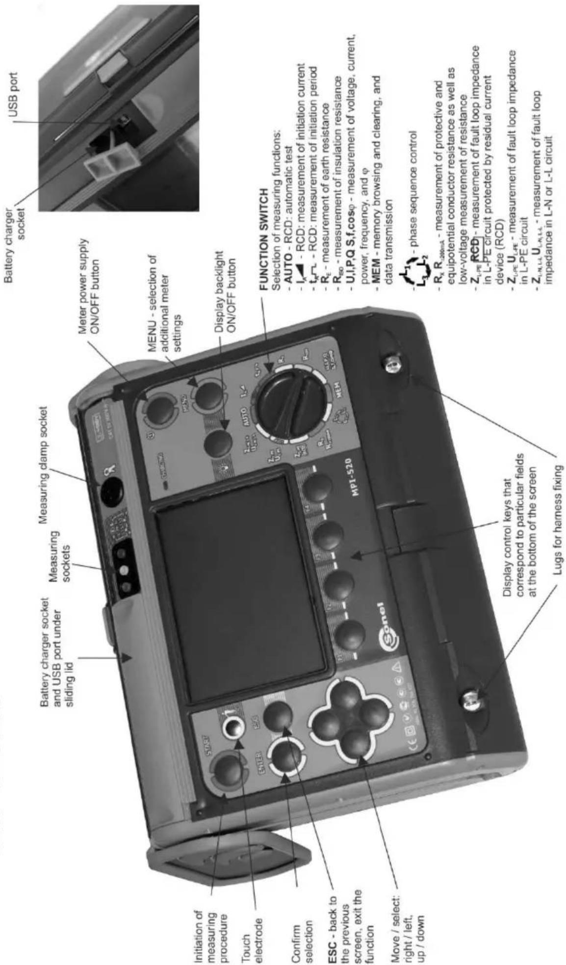
USER MANUAL
METER FOR ELECTRICAL INSTALLATION PARAMETERS MPI-520
CE
SONEL S. A.
Wokulskiego 11
58-100 Świdnica
Poland
The MPI-520 meter is a modern, easy and safe in use measuring device. Please acquaint yourself with the present manual in order to avoid measuring errors and prevent possible problems related to operation of the meter.
CONTENTS
1 Safety 5
2 Menu....6
2.1 Wireless transmission 6
2.2 Settings of measurements....7
2.2.1 Network voltage and frequency 7
2.2.2 Main result of short circuit loop impedance measurement 8
2.2.3 Measurement settings....8
2.2.4 Cell autoincrementing 8
2.3 Settings of the meter 9
2.3.1 LCD contrast....9
2.3.2 LCD backlight....10
2.3.3 Auto-OFF settings....10
2.3.4 Date and time....10
2.3.5 Factory (default) settings....11
2.3.6 Program update 11
2.4 Language selection.... 11
2.5 Information about manufacturer 11
3 Measurements....12
3.1 Measurement of alternating voltage and frequency 12
3.2 Checking correctness of PE (protective earth) connections.... 12
3.3 Measurement of current, active power, reactive power, apparent power and coefficient....13
3.4 Measurement of short circuit loop parameters 14
3.4.1 Measurement of short circuit loop parameters in L-N and L-L circuit 14
3.4.2 Measurement of short circuit loop parameters in L-PE circuit 16
3.4.3 Measurement of short circuit loop impedance in L-PE circuit protected with residual current device (RCD) 18
3.4.4 Prospective short-circuit current 19
3.5 Measurement of resistance-to-earth 20
3.6 Measurement of RCD parameters 23
3.6.1 Measurement of RCD disconnection current 23
3.6.2 Measurement of RCD disconnection time 25
3.6.3 Automatic measurement of RCD parameters 27
3.7 Measurement of insulation resistance.... 30
3.7.1 Double-lead measurement....30
3.7.2 Measurements with AutoISO-1000c adapter....33
3.7.3 Measurements by means of leads with UNI-Schuko outlet plug (WS-03 and WS-04).....34
3.8 Low-voltage measurement of resistance.... 36
3.8.1 Measurement of resistance of protective conductors and equipotential bonding with ±200 mA current....36
3.8.2 Measurement of resistance....38
3.8.3 Calibration of test leads....39
3.9 Checking sequence of phases 40
4 Memory of measurement result data....42
4.1 Recording measurement result data in the memory.... 42
4.2 Viewing memory data.... 43
4.3 Deleting memory data 46
5 Data transmission....47
5.1 Computer connection accessories 47
5.2 Data transmission with USB joint 47
5.3 Data transmission with OR-1 radio module 47
6 Power supply....49
6.1 Monitoring of the power supply voltage 49
6.2 Replacement of batteries (accumulators).... 50
6.3 Charging of accumulators 50
6.4 General principles regarding using Ni-MH accumulators 52
7 Cleaning and maintenance ....52
8 Storage....53
9 Dismantling and utilisation....53
10 Technical data....53
10.1 Basic data 53
10.2 Other technical data 60
10.3 Additional data 61
10.3.1 Additional uncertainties according to IEC 61557-2 (Rso)....61
10.3.2 Additional uncertainties according to IEC 61557-3 (Z)....61
10.3.3 Additional uncertainties according to IEC 61557-4 (R ±200 mA)....61
10.3.4 Additional uncertainties according to IEC 61557-5 ( R_E )....62
10.3.5 Additional uncertainties according to IEC 61557-6 (RCD) 63
11 Positions of the meter's cover 63
12 Manufacturer 63
1 Safety
MPI-520 meter is designed for performing check tests of protection against electric shock in mains systems. The meter is used for making the measurements the results of which determine safety of electrical installations. Therefore, in order to provide conditions for correct operation and the correctness of the obtained results, the following recommendations must be observed:
- Before you proceed to operate the meter, acquaint yourself thoroughly with the present manual and observe the safety regulations and specifications determined by the producer.
- The MPI-520 meter has been designed for the purpose of measurements of earth connection and equipotential bonding, ground resistivity, as well as clamps current measurements. Any application that differs from those specified in the present manual may result in a damage to the device and constitute a source of danger for the user.
- The device must be operated solely by appropriately qualified personnel with relevant certificates to realise measurements of electric installation. Operation of the meter realised by unauthorised personnel may result in damage to the device and constitute a source of danger for the user.
- Using this manual does not exclude the need to comply with occupational health and safety regulations and with other relevant fire regulations required during the performance of a particular type of work. Before starting the work with the device in special environments, e.g. potentially fire-risk/explosive environment, it is necessary to consult it with the person responsible for health and safety.
- It is unacceptable to operate the following:
⇒ A damaged meter which is completely or partially out of order,
⇒ A meter with damaged test leads insulation,
A meter stored for an excessive period of time in disadvantageous conditions (e.g. excessive humidity). If the meter has been transferred from a cool to a warm environment of a high level of relative humidity, do not realise measurements until the meter has been warmed up to the ambient temperature (approximately 30 minutes).
- It should be remembered that BAT message appearing on the display indicates that supply voltage of the meter is too low. This message signals also that the batteries must be replaced or the accumulator charged. Measurements performed by means of the meter whose supply voltage is too low are burdened with additional errors that are impossible to be estimated by the user. Such measurements must not be relied on in order to state correctness of protection of a network tested.
- Battery spill and damage to the meter may occur if discharged batteries are left in the meter.
- Before measurements may commence, make sure the test leads are connected to the appropriate measurement sockets.
- Do not operate a meter with an open or incorrectly closed battery (accumulator) compartment on power it from other sources than those specified in the present manual.
- The R _ISO inputs of the meter are protected electronically from overload (e.g. due to having been connected to a live circuit) up to 440V rms for 60 seconds.
• Repairs may be realised solely by an authorised service point.
ATTENTION!
Only accessories for a given device should be used. Use of different accessories can lead to errors in the test connection and can introduce additional measurement uncertainties.
Attention:
Due to continuous development of the meter's software, the actual appearance of the display, in case of some of the functions, may slightly differ from the display presented in this operating manual.
Note:
An attempt to install drivers in 64-bit Windows 8 may result in displaying "Installation failed" message.
Cause: Windows 8 by default blocks drivers without a digital signature.
Solution: Disable the driver signature enforcement in Windows.
2 Menu
The Menu is accessible in each position of the rotary switch.
①
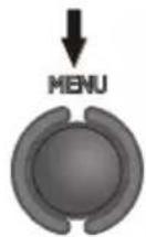
Press MENU push-button.
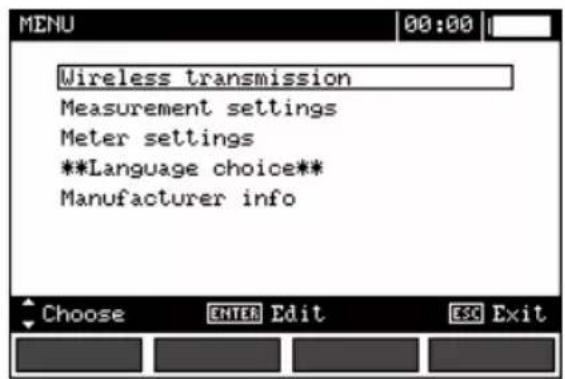
②
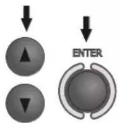
Select a proper item by means of ▲ push-buttons. Enter a selected option by pressing ENTER.
2.1 Wireless transmission
See chapter 5.3.
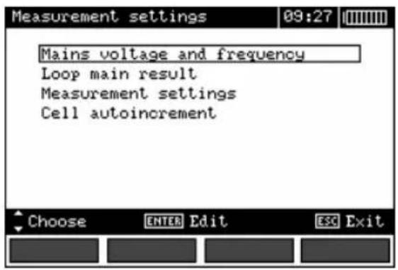
2.2 Settings of measurements
①
②
Select a proper item by means of ▲ push-buttons. Enter a selected option by pressing ENTER.
2.2.1 Network voltage and frequency
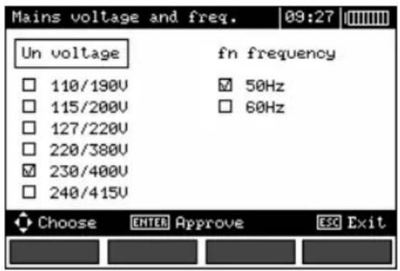
Before measurements a nominal network voltage U_n (110/190V, 115/200V, 127/220V, 220/380V, 230/400V or 240/415V) should be selected that is valid in the area where measurements are made. This voltage value is used for calculating the values of prospective short-circuit current.
Determination of network frequency, that is the source of potential interferences, is necessary in order to select a proper measuring signal frequency in resistance-to-earth measurements. Only the measurement conducted with a properly selected frequency of measuring signal will ensure optimum filtration of interferences. The meter is designed for filtration of interferences that originate from 50 Hz and 60 Hz networks.
①
②
By means of , push-buttons select a parameter to be changed, by means of , select network voltage and frequency. Confirm a choice made by means of ENTER push-button.
2.2.2 Main result of short circuit loop impedance measurement
①
②

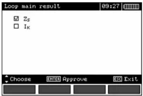
By means of ▲ push-buttons select main result in the form of impedance Z_s or prospective short-circuit current I_k ; confirm a choice made by means of ENTER push-button.
2.2.3 Measurement settings
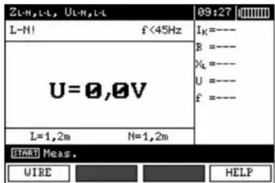
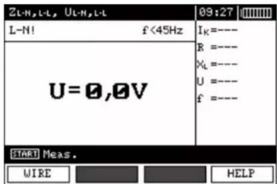
The setting enables activation/deactivation of the field displaying measurement settings. Show or hide the field with measurement settings by means of and push buttons, press ENTER push-button.
2.2.4 Cell autoincrementing
①
②
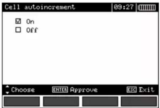
By means of ▲ push-buttons select the option of automatic incrementing of field number after its storing in the memory or the manual incrementing option (automatic incrementing is deactivated); confirm a choice made by means of ENTER push-button.
2.3 Settings of the meter
①
②
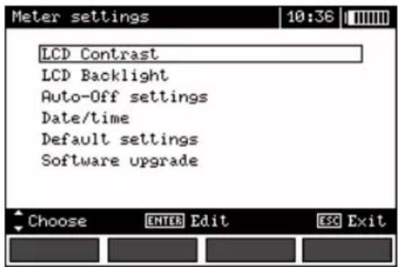
Select a suitable item by means of ▲, push-buttons; enter the edition of a selected option by means of ENTER push-button.
2.3.1 LCD contrast
①
②
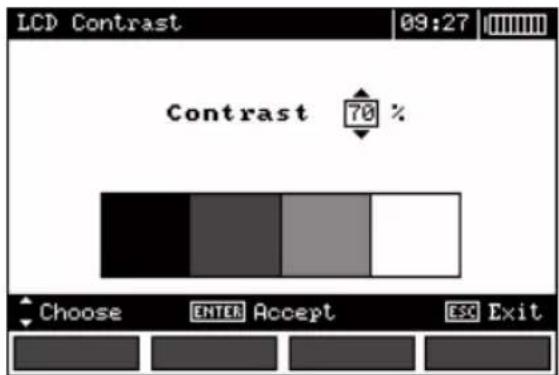
Select contrast value by means of ▲, push-buttons; confirm a choice made by means of ENTER push-button.
2.3.2 LCD backlight
①
②
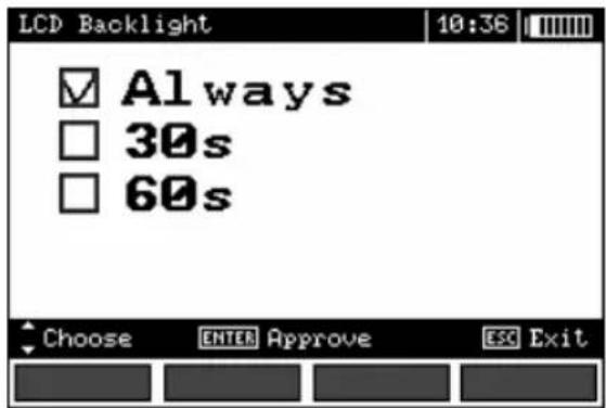
Use the ▲ and buttons to select the backlight off (with the
button) or time to Auto-off. Press ENTER to validate.
2.3.3 Auto-OFF settings
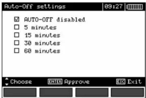
The setting defines time till automatic shutdown of idle meter.
①
②
Set the time or deactivate Auto-OFF by means of ▲push-buttons; confirm a choice made by means of ENTER push-button.
2.3.4 Date and time
By means of ◀, push-buttons select the value to be changed (day, month, year, hour, minute). Set a required value by means of ▲, ▼ push-buttons. When required settings are made, press ENTER push-button.
2.3.5 Factory (default) settings
In order to introduce factory (default) settings, highlight YES by means of ◀, ▶ push-buttons and press ENTER push-button.
2.3.6 Program update
ATTENTION!
This function may be used only by the users who are fluent in operation of computer equipment.
The guarantee does not cover defective operation of the device resulting from wrong use of this function.
ATTENTION!
A new package of batteries should be installed before programming or the accumulator should be charged.
During programming the meter must not be switched off as well as the transmission cable must not be disconnected.
Before updating the program, download the program that is use for programming the meter from the manufacturer's website, install this program on your computer and connect the meter to the computer.
Select Software upgrade in the MENU and follow the instructions displayed by the program.
2.4 Language selection
- By means of and ▲ push-buttons choose **Language choice** in the main MENU; press ENTER push-button.
- Select a required language by means of ▲ and ▼ push-buttons; press ENTER push-button.
2.5 Information about manufacturer
By means of ▲ and ▼ push-buttons choose Manufacturer info in the main MENU; press ENTER push-button.
3 Measurements
Remarks:
- A progress bar is displayed during long measurements.
- The content of this chapter should be thoroughly familiarized with since it describes the meter circuits, the methods of measurements and basic principles concerning interpretation of measurement results.
- Result of the latest measurement is remembered by the meter until a next measurement is started or measurement settings are changed or the measuring function is changed by means of the rotary switch or the meter is switched off. The result of the latest measurement is displayed on the screen for 20 seconds. It can be recalled by pressing ENTER push-button.
WARNING: During measurements (short circuit loop, RCD), earthed parts and parts accessible in the electrical installation being tested must not be touched.
WARNING: During a measurement, switching of the range switch is forbidden because it may damage the meter and pose a threat to the user.
3.1 Measurement of alternating voltage and frequency
The meter measures and displays alternating voltage and frequency of the network in all measuring functions except R_E , R_X , R±200mA , R_ISO -conductor. For U_L and R_ISO functions, only voltage is displayed. This voltage is measured for the frequencies within the range of 45..65 Hz as True RMS. If a frequency measured is outside the specified range, a proper message is displayed instead of the frequency value: f<45 Hz or f>65 Hz. Voltage is displayed as the main result only for U_L-N,L-L , Z_L-N,L-L , U_L-PE , Z_L-PE and U,I,P,Q,S,f,cosφ functions for Only U mode selected. The test leads should be connected as for a given measuring function.
3.2 Checking correctness of PE (protective earth) connections
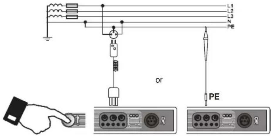
When the meter is connected according to the drawing, touch the touch electrode with a finger and wait for about 1 second. When voltage if found on PE, the device displays PE! message (error in the installation; PE lead is connected to the phase lead) and generates a continuous audio signal. This possibility is available for all measuring functions that apply to residual current devices (RCD) and short circuit loop.
Remarks:
WARNING:
When phase voltage is detected on PE lead, measurements must be immediately stopped and a fault in the installation must be removed.
- The person making a measurement must ensure that he/she is standing on a non-insulated floor during the measurement; otherwise the result of the measurement may be incorrect.
- The threshold value, which triggers the signal of exceeded allowable voltage on PE conduit, is approximately 50 V.
3.3 Measurement of current, active power, reactive power, apparent power and cosφ coefficient
①
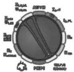
Set the rotary switch of function selection at U,I,P,Q,S,f,cosφ position.
②
flowchart
graph TD
    A["F1"] --> B["Arrow to F1"]
    B --> C["Arrow to ENTER"]
    C --> D["Arrow to ENTER"]
Press F1 push-button. Select "U,I,f,cosφ,P,Q,S" by means of and push-buttons and press ENTER push-button. (If you want to measure voltage or current only, select a proper position.)
③
Assemble the system according to the below drawing.

④
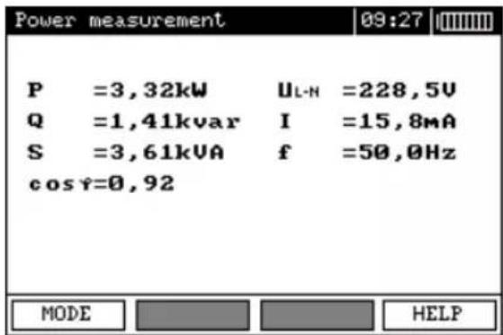
Read out the results.
3.4 Measurement of short circuit loop parameters

If there are residual current devices in the network tested, they should be bypassed by bridging for the period of impedance measurement. However, it should be remembered that the circuit tested is modified in this way and the results obtained may slightly differ from the actual results.
Each time after completion of measurements, modifications introduced to the installation for the period of measurements should be removed and operation of the residual current device should be checked.
The above remark does not apply to measurements of short circuit loop impedance with the use of Z_L-PE RCD function.

Measurements of fault loop impedance performed downstream of inverters are ineffective and their results are unreliable. This is due to the instability of internal impedance in inverter circuits during its operation. The measurements of fault loop impedance should not be performed directly downstream of inverters.
3.4.1 Measurement of short circuit loop parameters in L-N and L-L circuit
①
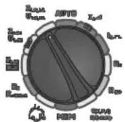
Set the rotary switch of function selection at Z_L-N,L-L/U_L-N,L-L position.
②
flowchart
graph TD
    A["F1"] --> B["Arrow to Top"]
    B --> C["Arrow to Bottom"]
    C --> D["ENTER"]
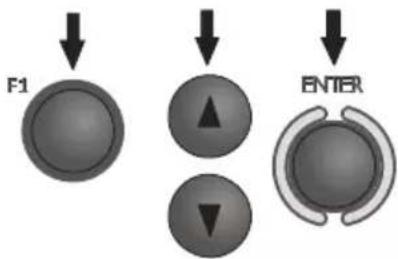
Press F1 push-button if lead length L needs to be selected. Select lead length by means of and push-buttons and press ENTER push-button.
③
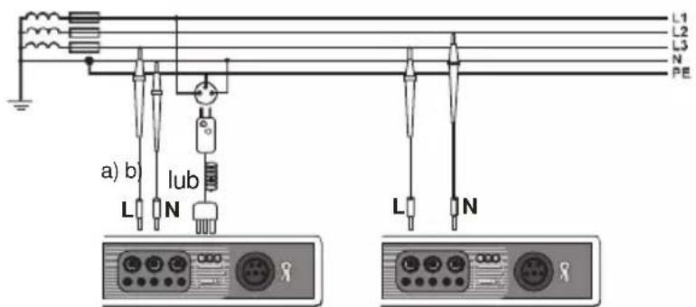
Connect test leads according to the drawing a) for measurement in L-N circuit or b) for measurement in L-L circuit
④
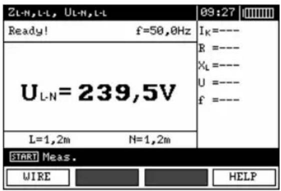
The meter is ready for measurement.
⑤
Make measurement by pressing START push-button
⑥
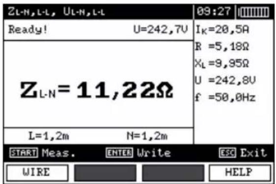
Read out the result.
The result is displayed on the screen for 20s.
The result can be recalled by pressing ENTER push-button.
Remarks:
- The result can be stored in the memory (see point 4.1).
- When many measurements are made in short time intervals, the meter may emit a large amount of heat. As a result of this, the housing of the device may become hot. This is a normal phenomenon and the meter is equipped with the protection against excessive temperature. After approximately 15 consecutive measurements of short circuit loop, wait until the instrument cools down. This limitation results from the high current measurement and multi-functionality of the meter.
- Minimum interval between successive measurements is 5 seconds. This minimum interval requirement is controlled by the meter. A next measurement can be made only when READY! message appears on the screen.
Additional information displayed by the meter
| READY! | The meter is ready for measurement. |
| L-N! | U_L-N voltage is incorrect for making a measurement. |
| L-PE! | U_L-PE voltage is incorrect for making a measurement. |
| N-PE! | U_N-PE voltage exceeds allowable value of 50V. |
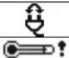 | Phase connected to N terminal instead of L terminal (for example, exchange of L and N in the mains socket. |
| Temperature exceeded. | |
| f! | Network frequency is outside the range of 45...65 Hz. |
| Error during measure | A correct result can not be displayed. |
| Loop circuit malfunction! | The meter should be serviced. |
| No U_L-N ! | Lack of U_L-N voltage before the principal measurement. |
| U>500 V! and continuous audio signal | Before measurement, voltage at test terminals exceeds 500 V. |
3.4.2 Measurement of short circuit loop parameters in L-PE circuit
①
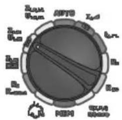
Set the rotary switch of function selection at Z_L-PE/U_L-PE position.
②
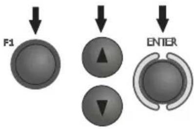
flowchart
graph TD
    A["F1"] --> B["Arrow to right"]
    B --> C["Arrow down"]
    C --> D["ENTER"]
Press F1 push-button if L lead length needs to be selected. Select a lead length by means of and push-buttons and press ENTER push-button.
③
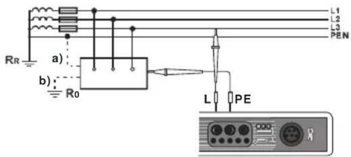
Connect test leads according to one of the drawings.
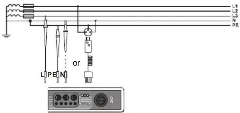
Checking effectiveness of protection against electric shock of the meter housing in case of: a) TN network b) TT network
④
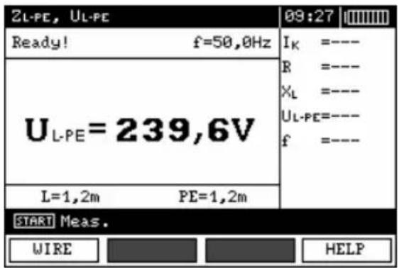
The meter is ready for measurement.
⑤
Make measurement by pressing START push-button.
⑥
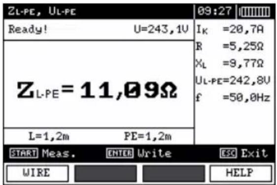
Read out the result.
The result is displayed on the screen for 20s. The result can be recalled by pressing ENTER push-button.
Remarks:
- Double lead measurement is possible when a test lead other that the lead with a mains socket is selected.
- Remaining issues connected with the measurements as well as the messages displayed are the same as those described for measurements in L-N circuit or L-L circuit.
3.4.3 Measurement of short circuit loop impedance in L-PE circuit protected with residual current device (RCD)
①
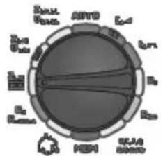
Set the rotary switch of function selection at Z_L-PE RCD position.
②
flowchart
graph TD
    A["FL"] --> B["Directional Arrow"]
    B --> C["ENTER"]
Press F1 push-button if L lead length needs to be selected. Select a lead length by means of ▲ and push-buttons and press ENTER push-button.
③
Connect test leads according to one of the drawings.
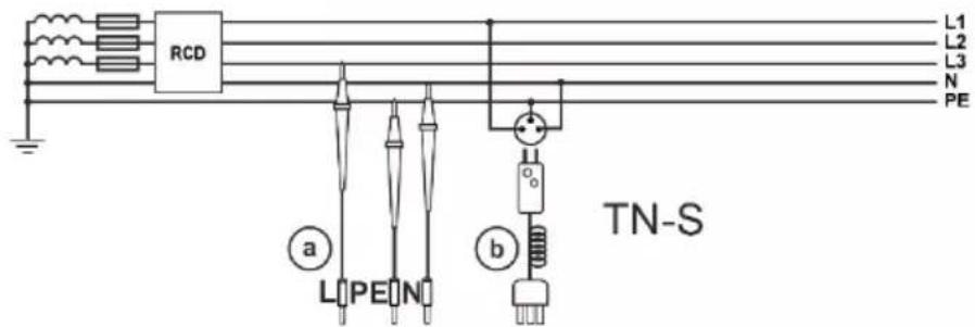
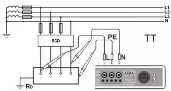
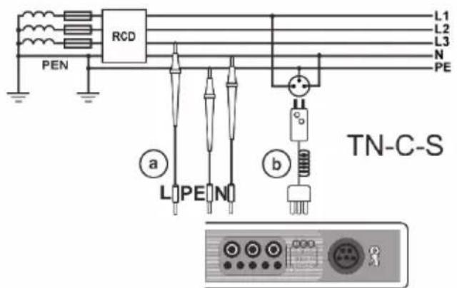
Remarks:
- Maximum measurement time is about 32 seconds. The measurement can be interrupted by pressing ESC push-button.
- In the electrical installations in which 30 mA - rated residual current devices are used, it may happen that the sum of leakage currents of the installation and the test current will trigger RCD. In such a situation, one should try to reduce leakage current of the network being tested (for example, by disconnecting load points).
- Remaining issues connected with the measurements as well as the messages displayed are the same as those described for measurements L-PE circuit.
- The function works for residual current devices of nominal current ≥ 30 mA.
3.4.4 Prospective short-circuit current
The meter always measures impedance. The short-circuit current is calculated according to the following formula:
$$ I _ {\overline {{k}}} \frac {U _ {n}}{Z _ {s}} $$
where: U_n - nominal voltage of the network being tested selected in MENU, Z_s - impedance measured.
On the basis of U_n nominal voltage selected (point 2.1.1), the meter automatically recognizes the measurement at phase voltage or phase-to-phase voltage and takes it into account in the calculations. If the voltage of the network being tested is outside the tolerance range, the meter will not be able to determine a proper nominal voltage for the short-circuit current calculation. In such a case, horizontal dashes will be displayed instead a short-circuit current value. The following diagram shows voltage ranges for which short-circuit current value is calculated.
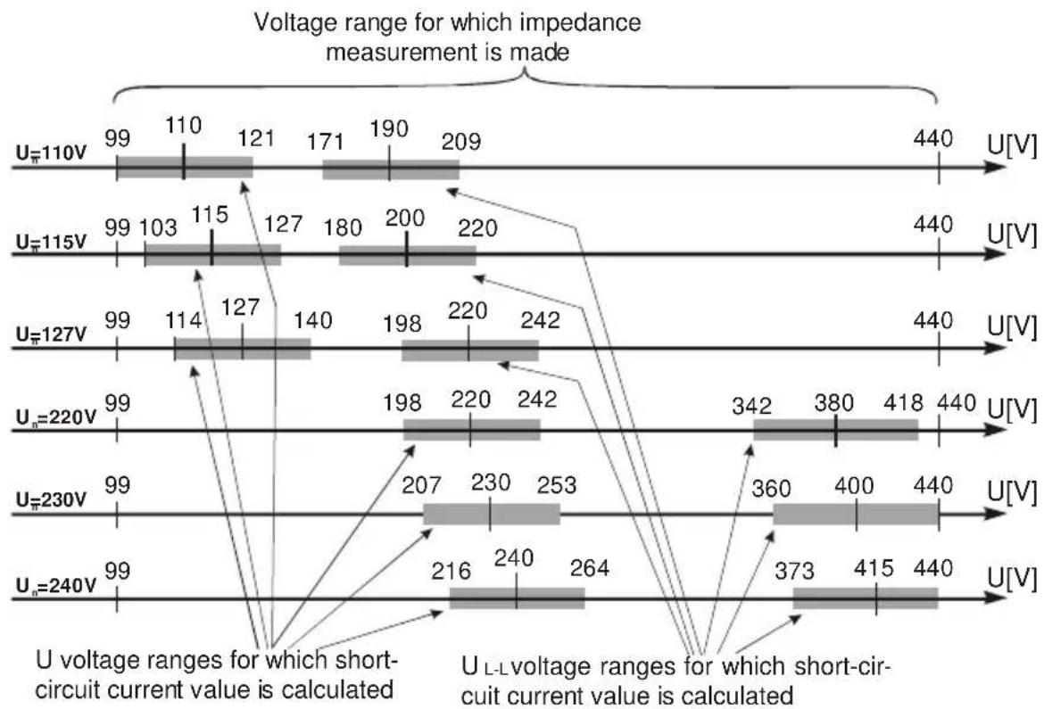
bar
| Voltage Range (V) | Current Value | | ----------------- | ------------- | | U=110V | 99 | | U=110V | 110 | | U=110V | 121 | | U=110V | 171 | | U=110V | 190 | | U=110V | 209 | | U=115V | 99 | | U=115V | 103 | | U=115V | 115 | | U=115V | 127 | | U=115V | 180 | | U=115V | 200 | | U=115V | 220 | | U=127V | 99 | | U=127V | 114 | | U=127V | 127 | | U=127V | 140 | | U=127V | 198 | | U=127V | 220 | | U=127V | 242 | | Un=220V | 99 | | Un=220V | 198 | | Un=220V | 220 | | Un=220V | 242 | | Un=230V | 99 | | Un=230V | 207 | | Un=230V | 230 | | Un=230V | 253 | | Un=230V | 360 | | Un=230V | 400 | | Un=230V | 440 | | Un=240V | 99 | | Un=240V | 216 | | Un=240V | 240 | | Un=240V | 264 | | Un=240V | 373 | | Un=240V | 415 | | Un=240V | 440 |3.5 Measurement of resistance-to-earth
The three-pole measuring method is the basic type of resistance-to-earth measurement.
①
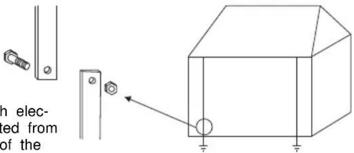
Disconnect earth electrode being tested from the installation of the building.
②
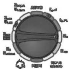
Set the rotary switch of function selection at R_E position.
③
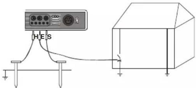
The current electrode (driven into earth) should be connected to H socket of the meter.
The voltage electrode (driven into earth) should be connected to S socket of the meter.
The earth electrode being tested should be connected to E socket of the meter.
The earth electrode being tested and the current electrode and the voltage electrode should be located in one line.
④
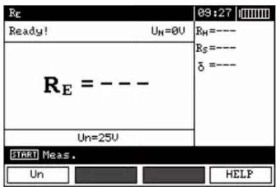
The meter is ready for measurement.
Value of interference voltage U_N can be read on the display.
⑤
Press F1 push-button to change test voltage.
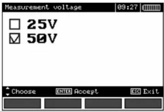
⑥
Select test voltage by means of push-buttons and confirm by pressing ENTER.
⑦
Press START push-button to start the measurement.
⑧
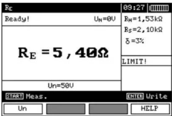
Read out the result.
Resistance of current electrode Resistance of voltage electrode Value of additional uncertainty caused by resistance of the electrodes
⑨
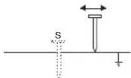
Repeat the measurements (points 3, 7, 8) shifting the voltage electrode several metres: the electrode should be shifted farther and closer to the earth electrode being tested. If RE measurement results differ from one another by more than 3%, the distance of the current electrode from the earth electrode being tested should be considerably increased and the measurements should be repeated.
Remarks:
Measurement of resistance-to-earth may be carried out if voltage of interferences does not exceed 24 V. Voltage of interferences is measured up to the level of 100 V but above 50 V it is signalled as dangerous. The meter must not be connected to voltages exceeding 100 V.
- Particular attention should be paid to quality of connection between the object being tested and the test lead – the contact area must be free from paint, rust, etc. - If resistance of test probes is too high, Earth electrode measurement will be burdened with additional uncertainty. Particularly high uncertainty of measurement occurs when a small value of resistance-to-earth is measured with probes that have a weak contact with earth (such a situation occurs frequently when the earth electrode is well made and the upper soil layer is dry and slightly conductive). In such a case, the ratio between resistance of the probes and resistance of the earth electrode tested is very high and consequently, uncertainty of measurement that depends on this ratio is also very high. The uncertainty is displayed on the screen in the column of additional results. In order to reduce the uncertainty, it is recommended to improve the contact between the probe and soil, for example, by dampening with water the place where the probe is driven into earth, driving the probe into earth in a different place or using a 80 cm-long probe. Test leads should also be checked as follows: check whether their insulation is not defective and whether the lead – banana plug – probe contact areas are not corroded or loosened. In majority of cases the measurement accuracy achieved is satisfactory. However, one should always be aware of uncertainty value the measurement is burdened with.
Additional information displayed by the meter
| RE>1,99 kΩ | Measuring range is exceeded. |
| UN! | Voltage at test terminals is higher than 24 V but lower than 50 V, measurement is blocked. |
| UN>50 V! and continuous audio signal | Voltage at test terminals is higher than 50 V. |
| NOISE! | Too low value of signal/noise ratio. |
| LIMIT! | Error caused by resistance of electrodes >30%. (Measured values are used in calculation of uncertainty.) |
 | Interruption in measuring circuit or resistance of test probes is higher than 60 kΩ. |
| Electrode resistance >50 kΩ | Resistance of electrodes within the range of 50...60 kΩ. |
| Aborted! | Measurement has been interrupted with ESC key button. |
3.6 Measurement of RCD parameters
Attention:
Measurement of U_B , R_E is always conducted with the use of sinusoidal current 0.4I_ n regardless of the settings concerning waveform and multiplication factor I_ n .
3.6.1 Measurement of RCD disconnection current
①
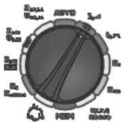
Set the rotary switch of function selection at ▲ position.
②
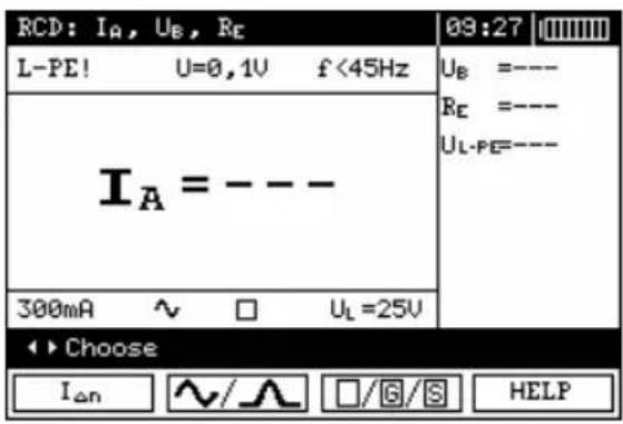
Press F1 I_An push-button and move to I_An selection.
Press F2 push-button and move to selection of current waveform.
Press F3 ☐/G/S push-button and move to selection of RCD type.

flowchart
graph TD
    A["Top Circle"] --> B["Down Arrow"]
    C["Bottom Circle"] --> D["Down Arrow"]
    E["Center Circle"] --> F["Shaded Ring"]
    G["ENTER"] --> H["Arrow Down"]
Select an appropriate item by means of ▲ and ▼ push-buttons and confirm by pressing ENTER.
③
Move to selection of a second group of parameters by means of and push-buttons.
④
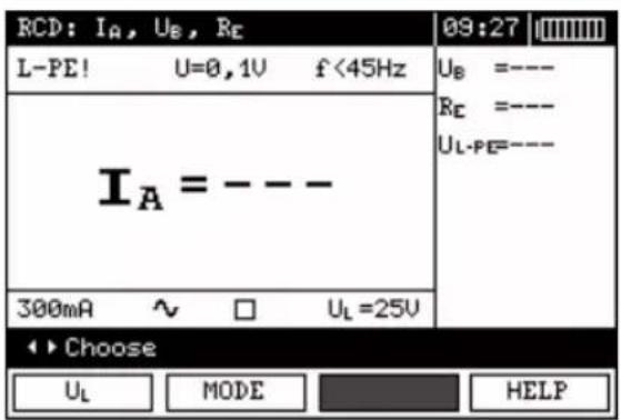
Press F1 _L push-button and move to selection of U_L .
Press F2 MODE push-button and move to selection of measurement mode.
Select an appropriate item by means of ▲ and buttons and confirm by pressing ENTER.
push-
⑤
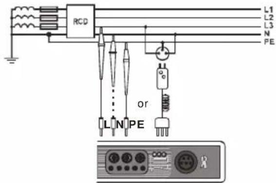
Connect the device to the installation according to the drawing.
⑥
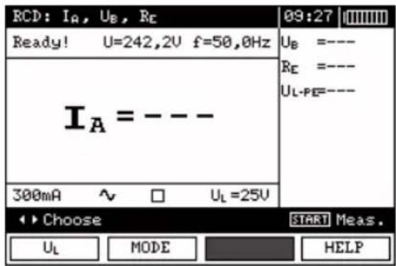
The meter is ready for measurement. Value of network voltage and frequency can be read on the display.
⑦
Press START to begin measurement.
⑧
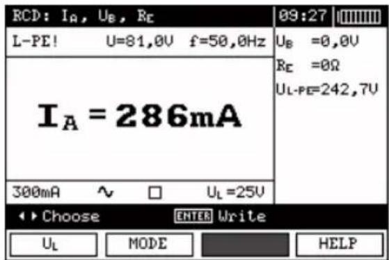
Read out the result.
Remark:
- Measurement of t_AI disconnection time for selective RCD is not available.
Additional information displayed by the meter
| U_B > U_L! | The touch voltage exceeds a preset U_L threshold value. |
| ! | ! placed on the right side of the result means that RCD is out of order |
| No U_L-N! | Lack of neutral lead that is necessary for I _ n constant and pulsed with direct current offset |
The remaining information is the same as for fault loop measurement (first 7 positions under point 3.4.1).
3.6.2 Measurement of RCD disconnection time
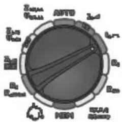
①
Set the rotary switch of function selection at position.
②
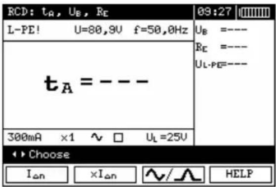
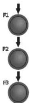
Press F1 I_An push-button and move to selection of I_An .
Press F2 _n push-button and move to selection of l_an multiplication factor
Press F3 △/▽/▽ push-button and move to selection of current waveform.
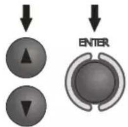
Select an appropriate item by means of ▲ and ▼ push-buttons and confirm by pressing ENTER.
③
Move to selection of a second group of parameters by means of and push-buttons.
④
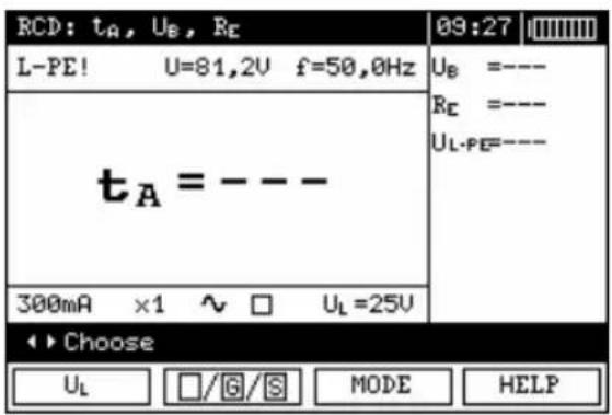
Press F1 L push-button and move to selection of UL
Press F2 □/G/S push-button and move to selection of RCD type.
Press F3 MODE push-button and move to selection of measurement mode.
Mark an appropriate position by means of ▲ and push-buttons and confirm by pressing ENTER.

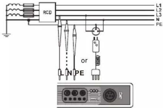
⑤
Connect the device to the installation according to the drawing.
⑥
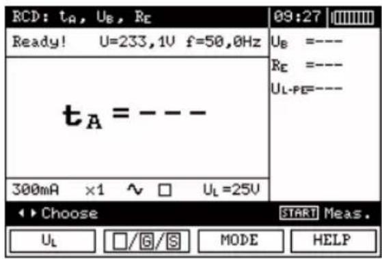
The meter is ready for measurement.
Value of network voltage and frequency can be read on the display.
⑦
Press START to begin measurement.
⑧
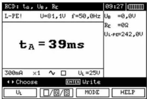
Read out the result.
Remarks and information are the same as for IA measurement.
3.6.3 Automatic measurement of RCD parameters
The meter enables automatic measurement of the following: RCD disconnection times ( t_A ), disconnection current ( I_A ), touch voltage ( U_B ) and resistance-to-earth ( R_E ). Additionally, there is a possibility of automatic measurement of short circuit loop impedance Z_L-PE RCD in a manner described in point 3.4.3. In the automatic mode, it is not necessary to actuate a measurement each time by means of START push-button. The operator of the meter only has to initiate a measurement by pressing START push-button once and switch RCD on each time after it is triggered. The below table shows maximum number of parameters measured and sequence of measurements for preset value of rated current I_ n , selected current waveform, type of RCD (standard / selective / short-time delay) and U_L voltage.
| No. | Parameters measured | Measurement conditions | |
| I_ n multiplication factor | Initial phase (polarization) | ||
| 1. | Z_L-PE | ||
| 2. | U_B R_E | ||
| 3. | t_A | 0,5I_ n | positive |
| 4. | t_A | 0,5I_ n | negative |
| 5.* | t_A | 1I_ n | positive |
| 6.* | t_A | 1I_ n | negative |
| 7.* | t_A | 2I_ n | positive |
| 8.* | t_A | 2I_ n | negative |
| 9.* | t_A | 5I_ n | positive |
| 10.* | t_A | 5I_ n | negative |
| 11.* | I_A | positive | |
| 12.* | I_A | negative | |
* points in which an efficient RCD should disconnected
①
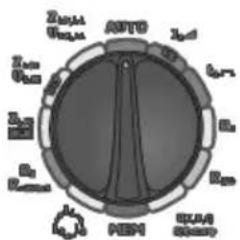
Set the rotary switch of function selection at AUTO position.
②
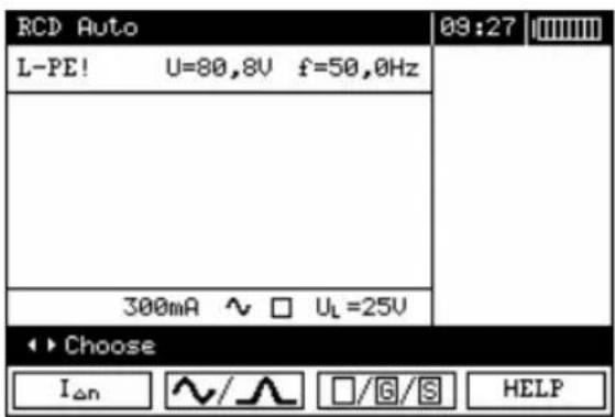
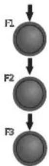
Press F1 I_An push-button and move to I_An selection.
Press F2 △/▽ push-button and move to selection of current waveform.
Press F3 □/G/S push-button and move to selection of RCD type.
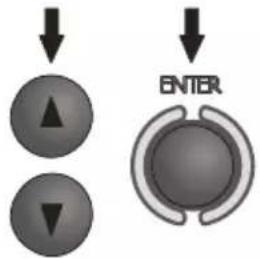
Select an appropriate item by means of ▲ and ▼ push-buttons and confirm by pressing ENTER.
③
Move to selection of a second group of parameters by means of and push-buttons.
④
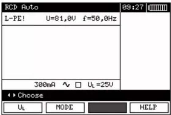
Press F1 _L push-button and move to selection of U_L .
Press F2 MODE push-button and move to selection of measurement mode.
Press F3 WIRE push-button and move to selection of L lead length (at Z_L-PE RCD measurement).
Select an appropriate item by means of ▲ and ▼ push-buttons and confirm by pressing ENTER.
⑤
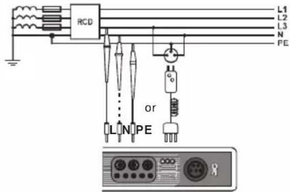
Connect the device to the installation according to the drawing.
⑥
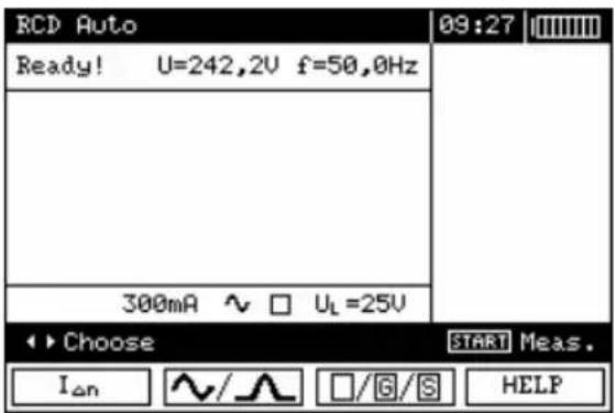
The meter is ready for measurement. Value of network voltage and frequency can be read on the display.
⑦
Press START push-button to start the measurement. If such measurements are selected that require triggering of RCD, operator of the meter should be in the vicinity of RCD and switch it on each time after it is triggered until the measurements are completed (a longer interruption may signify completion of the measurements).
⑧
![RCD ZL-PE [RCD] Auto 09:27 ZL-PE= 88% 10% L=1,2m 300mA ~ □ UL=25V ESC Abort measure](/content/2026/05/895323/images/cb63ad35f13e035e36e7e25d950a4108bf027ca45d250b95cfbe859181909d11.jpg)
Progress of measurement process is shown by progress bars: lower bar – total cycle; upper bar – measurement of Z_L-PE RCD and I_A .
⑨
![RCD ZL-PE [RCD] Auto 09:27 I_K =20,6A R =5,31Ω X_L =9,85Ω U_L-PE=239,9V f <45Hz L=1,2m 300mA ~ □ U_L=25V ←1/2> ENTER Write ESC Exit ◀Screen Screen▶](/content/2026/05/895323/images/370a8e18414070725be3c91e31cf50571d22fd491deb3985dd4862b44ac05dfe.jpg)
Read out the result.
10
Groups of results displayed are changed by means of F3 and F4 push-buttons.
![RCD ZL-PE [RCD] Auto 09:27 GOOD I_A =272mA+ =272mA- t_A(0.5I) >300ms+ >300ms- t_A(1I) =39ms+ =29ms- t_A(2I) =18ms+ =10ms- t_A(5I) =---- =---- L=1,2m 300mA ~ □ U_L=25V ←2/2> ENTER Write ESC Exit ◀Screen Screen▶](/content/2026/05/895323/images/c67ac5e9c3498c1ca804e6235148909313d30c6d08af667e6042bbe6344c9f46.jpg)
Remarks:
- The measurement is interrupted, if during measurement of U_B/R_E , RCD has been triggered at 0.5I_ n current or if RCD has not been triggered in other cases or if a preset value of safe voltage U_L has been exceeded.
- Store the result in the memory (see point 4.1) or press ESC push-button and display only network voltage and frequency.
- Remaining remarks and information are the same as for I_A and Z_L-PE measurement.
3.7 Measurement of insulation resistance
WARNING: The object tested must not be live.
3.7.1 Double-lead measurement
①
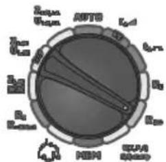
Set the rotary switch of function selection at R_ISO position.
②
Press F1 push-button and move to selection of test voltage U_N .
Select an appropriate item by means of ▲ and ▼ push-buttons and confirm by pressing ENTER.
Connect test leads according to the drawing.
③
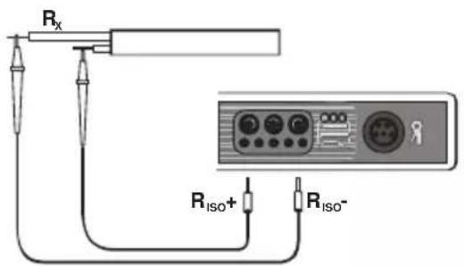
④
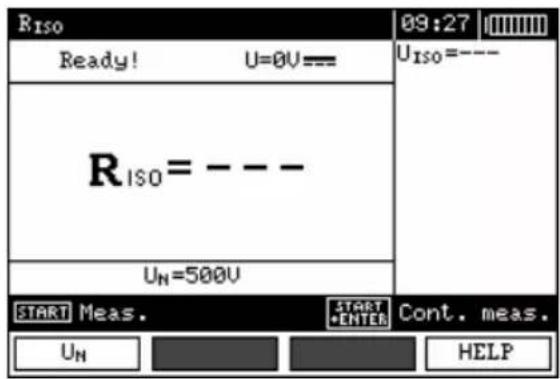
The meter is ready for measurement.
⑤
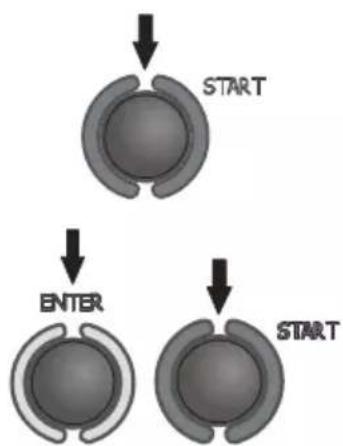
flowchart
graph TD
    A["Start"] --> B["ENTER"]
    B --> C["START"]
Press and hold START push-button.
Measurement is performed continuously when the push-button is held in the pressed position.
In order to maintain the measurement, press ENTER push-button while holding START push-button in the pressed position. In order to interrupt the mesaurement, press START push-button again.
⑥
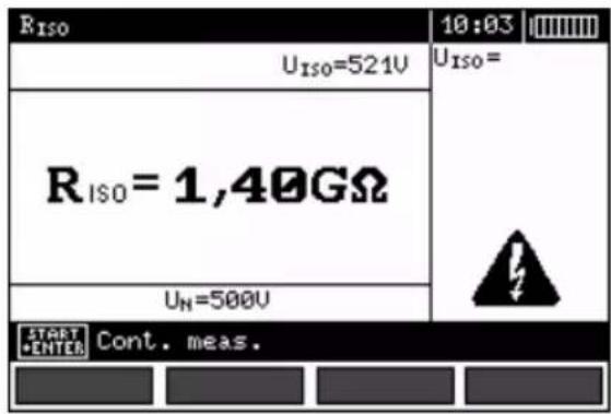
View of the screen during measurement performed with the use of ENTER push-button.

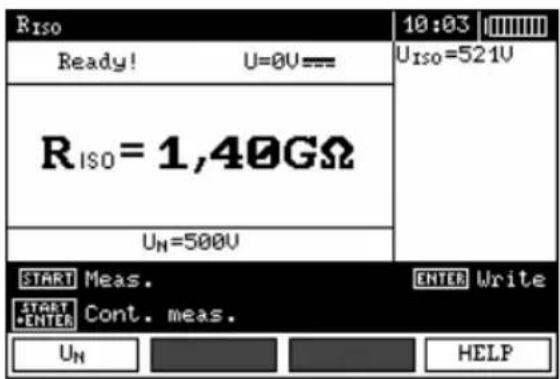
Read out the result.
Remarks:

During measurements of insulation resistance, dangerous voltage up to 1 kV occurs at the ends of test leads of MPI-520 meter.

It is forbidden to disconnect test leads and to change the position of the function switch before completion of measurement. Failure to obey the above instruction will lead to high voltage electric shock and make it impossible to discharge the object tested.
- The meter emits a continuous audio signal until test voltage reaches 90% of the preset value (and also when 110% of the preset value is exceeded).
- After completion of measurement, the capacitance of the object tested is discharged by shorting R_ISO + and R_ISO -terminals with resistance of 100 kΩ.
Additional information displayed by the meter
 | Test voltage is present on terminals of the meter. | |
| NOISE! | Interference voltage occurs on the object being tested. Measurement is possible but may be burdened with additional uncertainty. | |
| LIMIT 1! | Activation of current limit. The symbol displayed is accompanied by a continuous audio signal. | |
 | Wrong accessory is connected to test jack (other than WS-03 or WS-04 or AutoISO-1000c). | |
 | WS-03 or WS-04 lead for three-lead measurements is connected (measurement at L-PE, L-N and N-PE terminals). | |
3.7.2 Measurements with AutolISO-1000c adapter
①
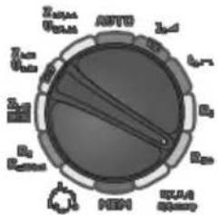
Set the rotary switch of function selection at R_iso position.
②
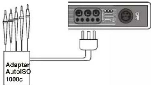
Connect AutoISO-1000c adapter. The meter detects this fact automatically and changes the appearance of the screen.
③
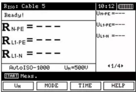
Press F1 U_N push-button and move to selection of test voltage U_N .
Press F2 MODE push-button and move to selection of lead type (3-, 4- or 5-wire lead).
Press F3 TIME push-button and move to selection of a single measurement time.
Select an appropriate item by means of ▲ and push-buttons and confirm by pressing ENTER.

④
Connect AutoISO-1000c adapter to the lead tested.
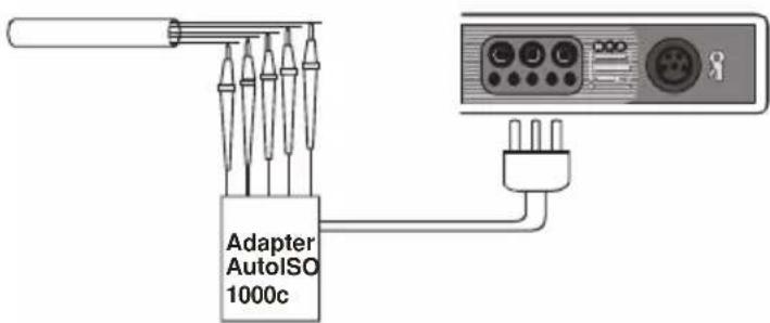
⑤
Press START push-buttons to start measurement. First, checking of voltages on particular pairs of wires is performed. If any of the voltages exceeds allowable voltage, the symbol of this voltage with “!” mark is displayed (e.g. _PE! ) and the measurement is interrupted.
⑥
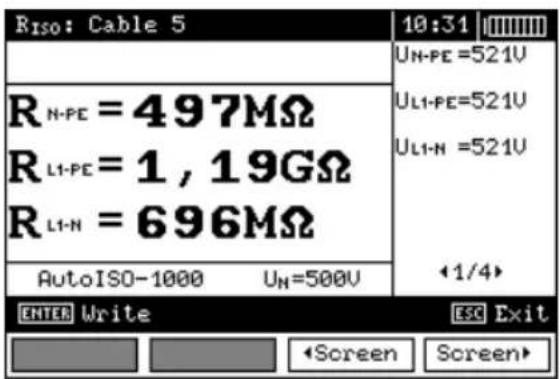
Read out the results.
Groups of results displayed are changed by means of F3 and F4 push-buttons.
Remarks:
- Remarks and messages the same as in point 3.7.1.
3.7.3 Measurements by means of leads with UNI-Schuko outlet plug (WS-03 and WS-04)
①
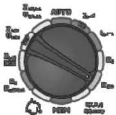
Set the rotary switch of function selection at R_ISO position.
②
natural_image
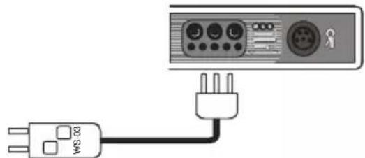
Pure electrical connection diagram showing a power plug connected to an outdoor control panel (no text or symbols)Connect WS-03 lead or WS-04 lead with UNI-Schuko outlet plug. The meter detects this fact automatically and changes the appearance of the screen.
③
flowchart
graph TD
    A["F1"] --> B["F2"]
    B --> C["F3"]
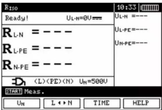
Press F1 U_N push-button and move to selection of test voltage U_N .
Press F2 L▶N push-button and move to selection of lead sequence: L, PE, N or N, PE, L.
Press F3 TIME push-button and move to selection of a single measurement time.
Select an appropriate item by means of ▲ and push-buttons and confirm by pressing ENTER.

Remark: If it is known that L and N leads in the socket are exchanged, after pressing F2 push-button, the sequence of (N)(PE)(L) can be selected in order to ensure that the meter provides correct results of measurements.
④
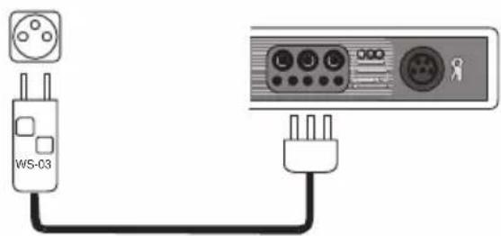
Connect WS-03 lead or WS-04 lead to the socket tested.
⑤
Press START push-buttons to start measurement. If any of the voltages exceeds allowable voltage value (50 V), Object under voltage message is displayed and the measurement is blocked.
⑥
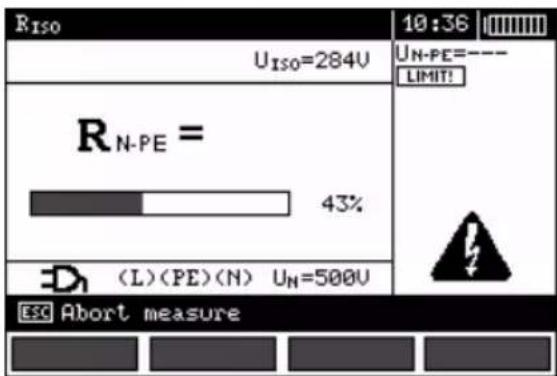
View of the screen during measurement. Symbol of the resistance being measured is displayed. Progress bar shows% of progress of total measurement.
⑦
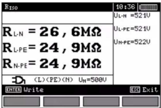
Read out the results.
Remarks:
- Remarks and messages are the same as in point 3.7.1.
3.8 Low-voltage measurement of resistance
3.8.1 Measurement of resistance of protective conductors and equipotential bonding with ±200 mA current
①
chemical
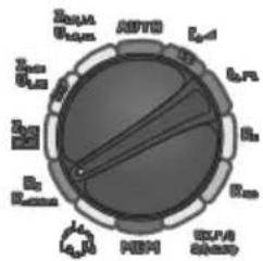
Electrochemical cell diagram with labeled components including nucleus, mitochondria, and iron electrodesSet the rotary switch of function selection at R_x R_±200 mA position.
②
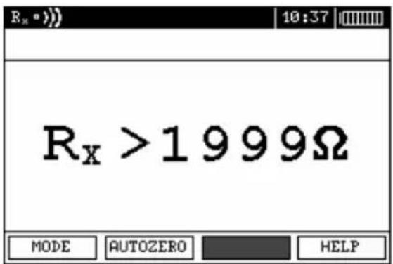
Press F1 push-button and move to selection of measurement mode.
③
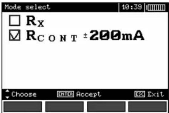
Select R_CONT ± 200 mA item by means of ▲ and ▼ push-buttons and confirm by pressing ENTER.
④
Connect the meter to the object tested. Measurement starts automatically.
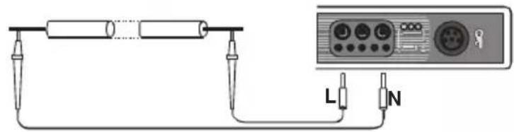
⑤
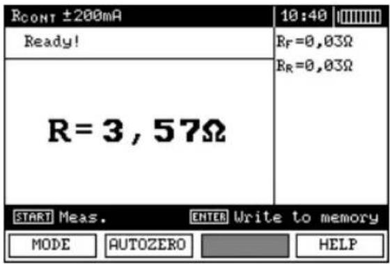
Read out the results.
⑥
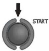
Press START push-button in order to start a next measurement without disconnecting test leads from the object.
Remarks:
ATTENTION!
When "Object under voltage" message is displayed, the object tested is live. The measurement is blocked. The meter must be immediately disconnected from the object.
Additional information displayed by the meter
| NOISE! | Interference voltage occurs on the object tested. The measurement is possible however it will be burdened with additional uncertainty that is specified in the technical data. |
3.8.2 Measurement of resistance
①
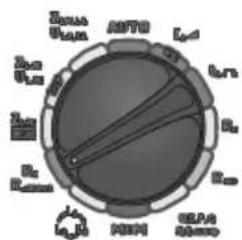
Set the rotary switch of function selection at R_x R_±200 mA position.
②
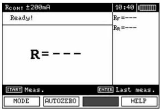
Press F1 push-button and move to selection of measurement mode.
③
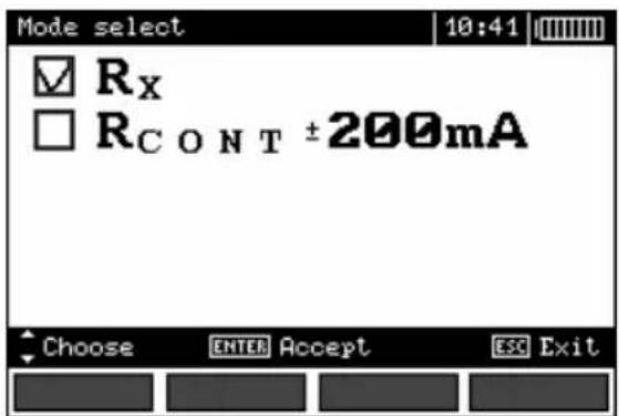
Select R_x position by means of and push-buttons and confirm by pressing ENTER.

④
Connect the meter to the object tested.
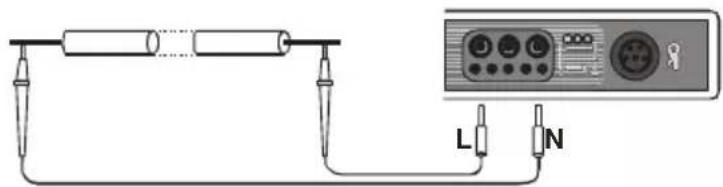
⑤
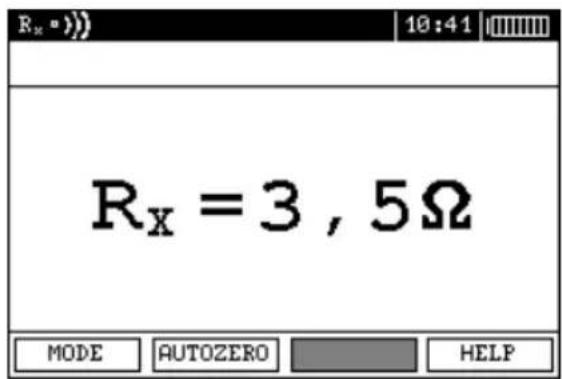
Read out the result.
Remarks:
- Remarks and messages are the same as in point 3.8.1.
3.8.3 Calibration of test leads
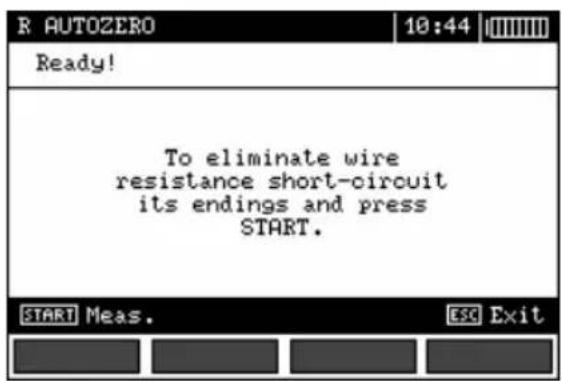
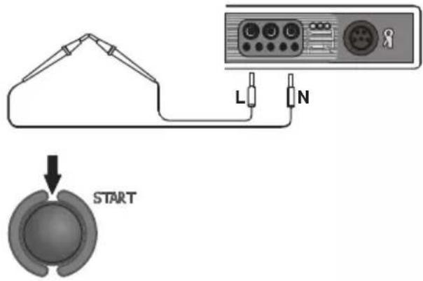
In order to eliminate the impact of the resistance of test leads on measurement result, the compensation (autozeroing) of resistance may be performed. For this purpose, R_x and R_±200 mA functions have AUTOZERO sub-function.
①
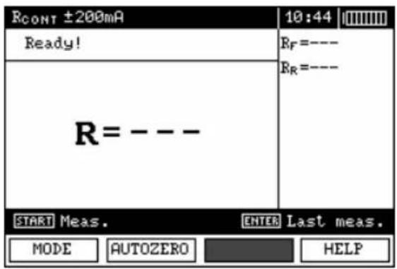
②
Press F2 push-button.
③
Follow the instructions displayed on the screen.
④
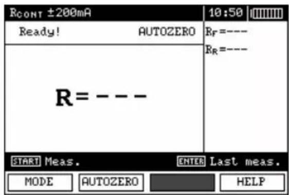
AUTOZERO message appears that confirms completion of test leads calibration.
⑤
In order to remove the calibration made (return to default calibration), perform the above-mentioned activities with test leads open.
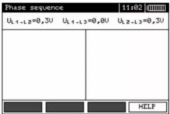
3.9 Checking sequence of phases
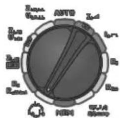
①
Set the rotary switch of function selection
at L_3 L_2 position.
②
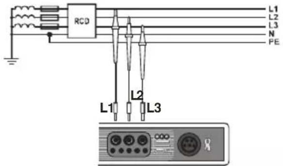
Connect the meter to the installation according to the drawing.
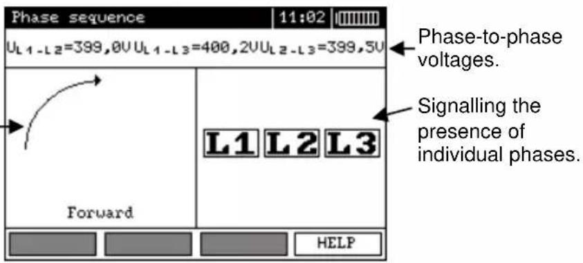
The arrow rotates to the right: correct sequence of phases; the arrow rotates to the left: incorrect sequence of phases.
4 Memory of measurement result data
MPI-520 meters are equipped with the memory that can store 50,000 single measurement results. The whole memory is divided into 10 memory banks each of them containing 99 memory cells. Thanks to dynamic memory allocation, each of the memory cells can contain different quantity of single measurement results, depending on the needs. Optimal use of the memory can be ensured in this way. Each measurement result can be stored in a memory cell marked with a selected number and in a selected memory bank. Thanks to this, the user of the meter can, at his/her option, assign memory cell numbers to individual measurement points and the memory bank numbers to individual objects as well as the user can perform measurements in any sequence and repeat them without losing other data.
Memory of measurement result data is not deleted when the meter is switched off. Thanks to this, the data can be later read or sent to a computer. Also, the number of a current memory cell or memory bank is not changed.
Remarks:
- Results of measurements performed for all measuring functions can be stored in one memory cell.
- When autoincrementing of memory cell number is deactivated, a single result (group of results) stored into the memory does not increase automatically the number of the current memory cell in order to enable storing in this memory cell successive measurement results concerning a given measurement point (object). If series of measurements are made for one function, autoincrementing of memory cell number can be set in MENU. Such autoincrementing takes place after each case of data storing in the memory (activation of autoincrementing – point 2.1.5).
- Only the results of the measurements started by pressing START key button can be stored in the memory (except autozeroing in low-voltage measurement of resistance).
- Deletion of the memory is recommended after reading the data or before performing a new series of measurements that may be stored into the same memory cells as the previous ones.
4.1 Recording measurement result data in the memory
①
Press ENTER after completion of measurement.

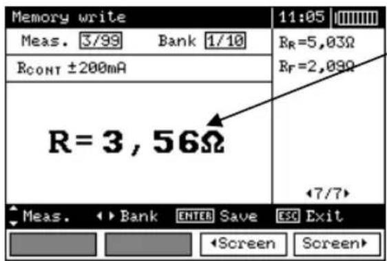
The cell is occupied for a given type of measurement.

Measurement (memory cell) is selected by means of and push-buttons; memory bank is selected by means of and push-buttons.
Storing of data in the memory is performed by means of ENTER push-button.

If you try to store data in an occupied memory cell, the following warning message will appear:
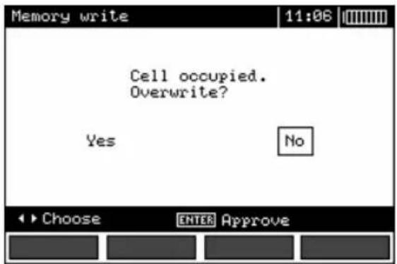

After selection of an option by means of and push-buttons, press ENTER push-button.
Remarks:
- In case of RCD the above warning message will appear also when an attempt is made to store a result of specific measurement (or result component) that has been made at different preset I_ n current or for a different preset type of RCD (standard / short-time delay / selective) than the measurements the results of which are already stored in this cell, despite the fact that the memory space designated for this result component may be free. When results of measurements made for a different type of RCD or a different I_ n current are stored, the results concerning a given RCD that have been stored previously will be lost. - Complete set of results (main result and supplementary results) for a given measuring function and preset measurement settings are stored in the memory.
4.2 Viewing memory data

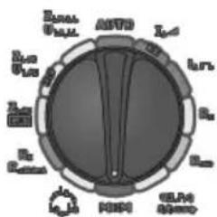
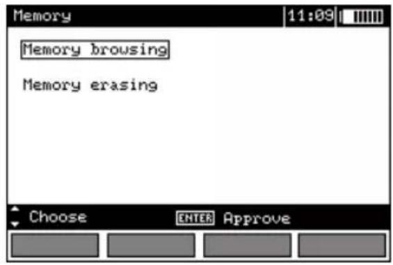
Set the rotary switch of function selection at MEM position.
②
Select "Memory browsing" by means of and push-buttons.
③
Press ENTER push-button.
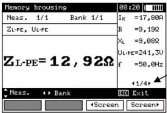
First of the four results stored in this cell.
④
Select memory bank by means of and push-buttons; select a memory cell by means of and push-buttons; particular results or components of the result are selected by means of F3 and F4 push-buttons.
The following table specifies the sequence of data storing for individual measurement results.
| No. | Main result | Supplementary results |
| 1 | Z_L-PE or I_K | k or Z_L-PE |
| R | ||
| XL | ||
| U_L-PE | ||
| f | ||
| U_B | ||
| 2 | t_A at 0.5I_ n , sinusoidal current, positive and negative initial phase | R_E |
| U_-N | ||
| 3 | t_A at 1I_ n , sinusoidal current, positive and negative initial phase t_A at 2I_ n , sinusoidal current, positive and negative initial phase t_A at 5I_ n , sinusoidal current, positive and negative initial phase | |
| 4 | I_A sinusoidal current, positive and negative initial phase | |
| 5-7 | as above for unidirectional pulsed current and positive and negative polarization | |
| 8-10 | as above for unidirectional pulsed current with direct current offset and positive and negative polarization | |
| 11-13 | as above for direct current and positive and negative polarization | |
| 14 | Z_L-N (Z_L-I) or I_K | k or Z_L-N (Z_L-L) |
| R | ||
| X_L | ||
| U_-N (U_L-L) | ||
| f | ||
| 15 | Z_L-PE or I_K | k or Z_L-PE |
| R | ||
| X_L | ||
| U_-PE | ||
| f | ||
| 16 | R_E | R_H |
| R_S | ||
| 17 | R_ISO | U_ISO |
| [LIMIT I!] | ||
| [NOISE!] | ||
| or | ||
| 18 | CABLE 3: R_ISO(N-PE) , R_ISO(L1-PE) , R_ISO(L1-N) , | U_ISO , [LIMIT I], [NOISE] U_ISO , [LIMIT I], [NOISE] U_ISO , [LIMIT I], [NOISE] |
| or | ||
| 19 | CABLE 4: R_ISO(L1-N) , R_ISO(L2-N) , R_ISO(L3-N) , | U_ISO , [LIMIT I], [NOISE] U_ISO , [LIMIT I], [NOISE] U_ISO , [LIMIT I], [NOISE] |
| 20 | CABLE 4: R_ISO(L1-L2) , R_ISO(L1-L3) , R_ISO(L2-L3) , | U_ISO , [LIMIT I], [NOISE] U_ISO , [LIMIT I], [NOISE] U_ISO , [LIMIT I], [NOISE] |
| or | ||
| 21 | CABLE 5: R_ISO(N-PE) , R_ISO(L1-PE) , R_ISO(L1-N) , | U_ISO , [LIMIT I], [NOISE] U_ISO , [LIMIT I], [NOISE] U_ISO , [LIMIT I], [NOISE] |
| 22 | CABLE 5: R_ISO(L2-N) , R_ISO(L3-N) , R_ISO(L1-L2) , | U_ISO , [LIMIT I], [NOISE] U_ISO , [LIMIT I], [NOISE] U_ISO , [LIMIT I], [NOISE] |
| 23 | CABLE 5: R_ISO (L1-L3), R_ISO (L2-L3), R_ISO (L2-PE), | U_ISO , [LIMIT I], [NOISE] U_ISO , [LIMIT I], [NOISE] U_ISO , [LIMIT I], [NOISE] |
| 24 | CABLE 5: R_ISO (L3-PE), | U_ISO , [LIMIT I], [NOISE] |
| 25 | R ±200 mA | R_F |
| R_R | ||
| [NOISE !] | ||
Remarks:
- While viewing the memory, empty measurements and memory banks are not accessible. "Measurement 1/20" signifies the first of the 20 measurements; measurements 21...99 are empty and inaccessible. The same principle applies to memory banks. If the memory is stored in a non-continuous manner, empty measurements and memory banks are omitted while the memory is being viewed.
4.3 Deleting memory data
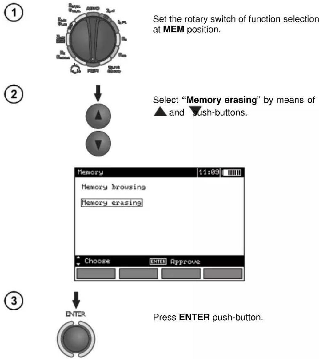
Set the rotary switch of function selection at MEM position.
Select "Memory erasing" by means of ▲ and ▼ push-buttons.
Press ENTER push-button.
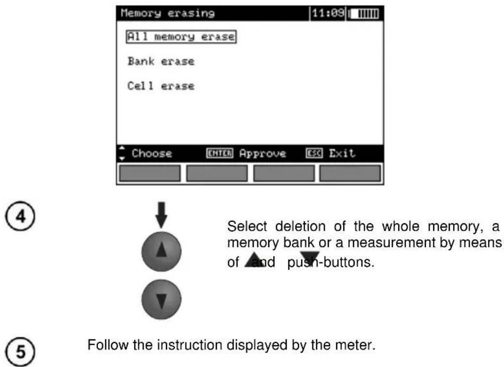
5 Data transmission
Remarks:
- Data transmission is not possible during the charging of accumulators.
- Starting with firmware version 2.95, the support for data transmission via OR-1 module is disabled.
5.1 Computer connection accessories
What is necessary in order to operate the meter with a computer is additional accessories, namely a USB cable and appropriate software. If the required accessories such have not been purchased along with the meter, then they are available from the manufacturer or an authorised distributor.
The accessories may be used in case of many devices manufactured by SONEL S.A. which are equipped with the USB interface.
Detailed information regarding software is available from the manufacturer or an authorised distributor.
5.2 Data transmission with USB joint
- Set the rotational function selector at MEM.
- Connect the cable to the USB port of the computer and the USB socket of the meter.
- Start the programme.
5.3 Data transmission with OR-1 radio module
- Connect OR-1 module to the USB socket of the PC.
- Start data filing programme.
- Select Wireless transmission in the main MENU of the meter
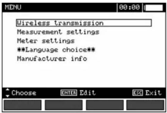
or set the function switch to MEM and press F1.
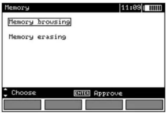
- If a PIN code change is necessary, select Modify PIN code.
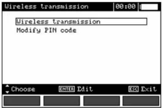
- Set the required code with the cursors.
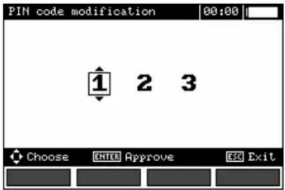
The same code must be entered in the computer programme. It is used for securing transmission. 6. To start transmission, select Wireless transmission in the MENU or press F1 in the MEM position. The following messages will be displayed: Connecting and then Connection active. If it is impossible
to establish connection the message Wireless connection lost will appear. Once the connection is established, follow the programme manual for data filing.
Note:

Standard pin for OR-1 is the „123”. Settings in the meter according to section 2.2.
6 Power supply
6.1 Monitoring of the power supply voltage
The level of the charge of the batteries or accumulators is currently indicated by the symbol in the right upper corner of the display:
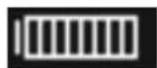
Bartery charged.
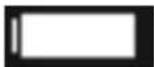
Bartery low.
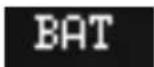
Bartery fully discharged.
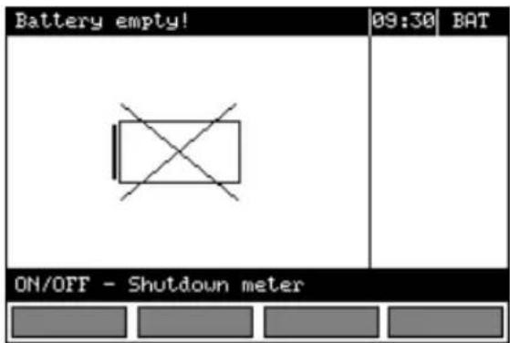
Bartery fully discharged, measuring blocked.
Note:
- The displayed BAT symbol means insufficient power supply voltage and the need to charge the accumulators,
- Measurements realised with an insufficient meter power supply voltage are distorted with additional errors which are impossible to ascertain by the user and thus they cannot constitute a basis for a conclusion of correctness of the tested earthing system.
6.2 Replacement of batteries (accumulators)
MPI-520 meter is powered by 4 batteries (LR14). It can be also powered by the manufacturer's accumulator package (SONEL NiMH).
Battery charger is installed inside the meter and cooperates only with the manufacturer's accumulator package. The charger is powered by external power supply adapter. It can be also powered from the car cigarette lighter socket. The accumulator package as well as the power supply adapter belong to additional accessories and can be purchase separately.
WARNING:
If the test leads are left in the sockets during replacement of the batteries or the package of accumulators, there is a risk of electric shock with a dangerous voltage.
In order to replace the package of accumulators it is necessary to do the following:
- Remove all the test leads from the sockets and turn the meter off,
- Remove the four screws of the accumulators/batteries compartment (in the lower part of the casing),
- Remove the compartment,
- Remove the compartment cover and remove the accumulators,
- Insert a new package of accumulators,
- Insert (snap) the compartment cover,
- Insert the compartment in the meter,
- Replace the four screws of the accumulators/batteries compartment.
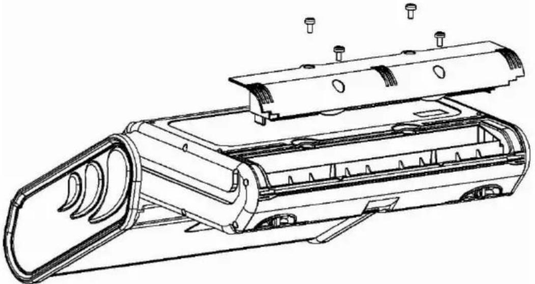
natural_image
Technical line drawing of a mechanical device with internal components and mounting holes (no text or symbols)NOTE!
Do not use the meter when the accumulator compartment is removed or open or power it from other sources than those mentioned in the present manual.
6.3 Charging of accumulators
Charging commences once the power supply has been connected to the meter regardless of the fact whether the meter is on or off. During charging the screen looks as it is presented in the following illustration. The accumulators are charged in accordance with the algorithm of „quick charge” – this process permits to reduce the duration of charging to approximately four hours. The end of the process
of charging is signalled by: Charging finished. In order to turn the device off, remove the power supply plug of the charger.
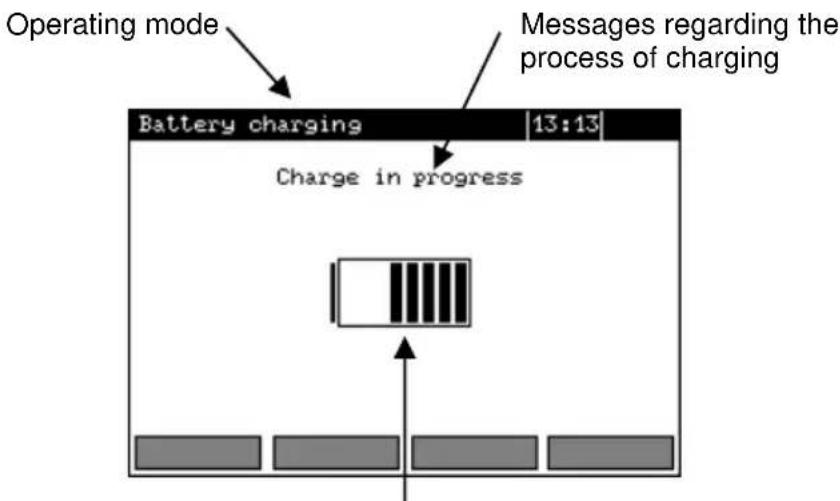
Charging progress, the changing interior section symbolizes charging
Note:
- As a result of interferences in the network it is possible that the process of charging of accumulators will finish too fast. In the case too short a time of charging is detected it is necessary to remove the plug of the charger and start charging anew.
Additional informations displayed by the meter
| Message | Cause | Proceeding |
| Battery connection error! | Excessive voltage at the accumulator package during charging. | Check the contacts of the accumulator package. Should the problem persist, replace the package. |
| No battery! | No communication with the accumulator controller or batteries compartment put in. | Check the contacts of the accumulator package. Should the problem persist, replace the package. Put the accumulators compartment instead of batteries. |
| Battery temperature too low! | The ambient temperature is lower than 10°C | It is not possible to charge the accumulators correctly in such a temperature. Place the meter in a warm place and commence the charging mode anew.The present message may be displayed also in the case of deep discharging of the accumulators. It is then recommended to try to turn the charger repeatedly. |
| Precharge error | A damaged or deeply discharged accumulator package | The message is displayed for a while and then the precharge process begins again. If after several attempts the message: Battery temperature too high! is displayed, replace the package. |
6.4 General principles regarding using Ni-MH accumulators
- If you do not use the device for a prolonged period of time, then it is recommended to remove the accumulators and store them separately.
- Store the accumulators in a dry, cool and well ventilated place and protect them from direct sunlight. The temperature of the environment in the case of prolonged storage should not exceed 30^a C. If the accumulators are stored for a long time in a high temperature, then the occurring chemical processes may reduce their lifetime.
- Accumulators NiMH resist normally 500-1000 charging cycles. The accumulators reach their maximum capacity after being formatted (2-3 charge and discharge cycles). The most important factor which influences the lifetime of an accumulator is the depth of discharge. The deeper the discharge of the accumulator, the shorter its lifetime.
- The memory effect is limited in the case of NiMH accumulator. These accumulators may be charged at any point with no serious consequences. However, it is recommended to discharge them completely every few cycles.
- During storage of Ni-MH accumulators they are discharged at the rate of approximately 30% per month. Keeping accumulators at high temperatures may accelerate this process even 100%. In order to prevent excessive discharge of accumulators, after which it would be necessary to format them, it is recommended to charge the accumulators from time to time (even if not in use).
- Modern fast chargers detect both too low and too high a temperature of accumulators and react to the situation adequately. Too low a temperature should prevent the start of the process of charging, which might damage the accumulator irreparably. An increase of the temperature of the accumulator is a signal to stop charging and is a typical phenomenon. However charging at a high temperature of the environment apart from reducing the lifetime causes an accelerated increase of the temperature of the accumulator, which will be not charged to its full capacity.
- Remember that in the case of quick charging accumulators are charged to approximately 80% of their capacity; better results may be obtained if the process of charging is continued: the charger goes then to the phase of charging with a low current and after next couple of hours the accumulators are charged to their full capacity.
- Do not charge or use accumulators in extreme temperatures. Extreme temperatures reduce the lifetime of batteries and accumulators. Avoid placing devices powered from accumulators in very hot environments. The nominal working temperature must be absolutely observed.
7 Cleaning and maintenance
NOTE!
Apply solely the maintenance methods specified by the manufacturer within the present manual.
The casing of the meter may be cleaned with a soft, damp cloth using all-purpose detergents. Do not use any solvents or cleaning agents which might scratch the casing (powders, pastes, etc.).
Clean the probe with water and dry it. Before the probe is stored for a prolonged period of time it is recommended to grease it with any machine lubricant.
The reels and test leads should be cleaned with water and detergents, and then dried.
The electronic system of the meter does not require maintenance.
8 Storage
In the case of storage of the device, the following recommendations must be observed:
- Disconnect all the test leads from the meter.
- Clean the meter and all its accessories thoroughly.
• Wind the long test leads onto the reels.
- In the case the meter is to be stored for a prolonged period of time, the batteries must be removed from the device.
- In order to prevent a total discharge of the accumulators in the case of a prolonged storage, charge them from time to time.
9 Dismantling and utilisation
Worn-out electric and electronic equipment should be gathered selectively, i.e. it must not be placed with waste of another kind.
Worn-out electronic equipment should be sent to a collection point in accordance with the law of worn-out electric and electronic equipment.
Before the equipment is sent to a collection point, do not dismantle any elements.
Observe the local regulations concerning disposal of packages, worn-out batteries and accumulators.
10 Technical data
10.1 Basic data
⇒ Abbreviation „m.v.” used in the specification of accuracy signifies standard measured value.
Measurement of alternating voltages (True RMS)
| Range | Resolution | Accuracy |
| 0.0...299.9 V | 0.1 V | ±(2% m.v. + 6 digits) |
| 300...500 V | 1 V | ±(2% m.v. + 2 digits) |
• Frequency range: 45...65 Hz
Measurement of frequency
| Range | Resolution | Accuracy |
| 45.0...65.0 Hz | 0.1 Hz | ±(0.1% m.v. + 1 digit) |
• Voltage range: 50...500 V
Measurement of current (True RMS)
| Range | Resolution | Accuracy |
| 0.0..99.9 mA | 0.1 mA | ±(5% m.v. + 3 digits) |
| 100..999 mA | 1 mA | |
| 1.00..9.99 A | 0.01 A | ±(5% m.v. + 5 digits) |
| 10.0..99.9 A | 0,1 A | |
| 100 ... 400 A | 1 A |
- Nominal network frequency f_n : 50 Hz, 60 Hz
*) Error of clamp must be additionally taken into account
| Range[W], [VA], [var] | Resolution[W], [VA], [var] | Accuracy(with regard to apparent power S) ^1 |
| 0.0..99.9 | 0,1 | ±(7% m.v. + 3 digits) |
| 100..999 | 1 | |
| 1.00..9.99 k | 0.01 k | ±(7% m.v. + 5 digits) |
| 10,0..99,9 k | 0.1 k | |
| 100 ... 200 k | 1 k |
• Voltage range: 0...500 V
- Current range: 0...400 A
- Nominal network frequency f_n : 50 Hz, 60 Hz
• Number of phases of the circuit tested: 1
• Range of cosφ display: 0.00..1.00 (resolution 0.01)
*) U: 50...500 V, I: 10 mA...400 A
Error of clamp must be additionally taken into account
Measurement of short circuit loop impedance Z_L-PE , Z_L-N , Z_L-L
Measurement of short circuit loop impedance Z_s
Test range according to IEC 61557:
| Test lead | Test range Zs |
| 1.2 m | 0.13...1999 Ω |
| 5 m | 0.17...1999 Ω |
| 10 m | 0.21...1999 Ω |
| 20 m | 0.29...1999 Ω |
| WS-03, WS-04 | 0.19...1999 Ω |
Display range:
| Display range | Resolution | Accuracy |
| 0...19.99 Ω | 0.01 Ω | ±(5% m.v. + 3 digits) |
| 20.0...199.9 Ω | 0.1 Ω | |
| 200...1999 Ω | 1 Ω |
- Nominal working voltage U nL-N √ U nL-L : 110/190 V, 115/200 V, 127/220 V, 220/380 V, 230/400 V, 240/415 V
• Working range of voltage: 95...270 V (for Z_L-PE and Z_L-N ) and 95...440 V (for Z_L-L ) - Nominal network frequency f_n : 50 Hz, 60 Hz
• Working range of frequency: 45...65 Hz
• Maximum test current (for 415 V): 41.5 A (10 ms)
• Control of correctness of PE terminal connection by means of a touch electrode
Indications of short circuit loop resistance R_S and short circuit loop reactance X_S
| Display range | Resolution | Accuracy |
| 0..19.99 Ω | 0.01 Ω | ±(5% + 5 digits) of Z_S value |
- Calculated and displayed for a value of Z_s<20
Indications of short-circuit current I_K
Test ranges according to IEC 61557 can be calculated on the basis of test ranges for Z_s and nominal voltages.
| Display range | Resolution | Accuracy |
| 0.055...1.999 A | 0.001 A | Calculated on the basis of error for fault loop |
| 2.00...19.99 A | 0.01 A | |
| 20.0...199.9 A | 0.1 A | |
| 200...1999 A | 1 A | |
| 2.00...19.99 kA | 0.01 kA | |
| 20.0...40.0 kA | 0.1 kA |
- Prospective fault current calculated and displayed by the meter may slightly differ from the value calculated by the user with a calculator, basing on the displayed value of the impedance, because the meter calculates the current from unrounded value of fault loop impedance (which is used for displaying). As the correct value, consider current value, displayed by the meter or by firmware.
Measurement of short circuit loop impedance Z_L-PE RCD (without triggering of RCD)
Measurement of short circuit loop impedance Z_6
Test range according to IEC 61557: 0.50...1999 Ω for 1.2 m, WS-03 and WS-04 leads and 0.51...1999 Ω for 5 m, 10 m and 20 m leads
| Display range | Resolution | Accuracy |
| 0...19.99 Ω | 0.01 Ω | ±(6% m.v. + 10 digits) |
| 20.0...199.9 Ω | 0.1 Ω | ±(6% m.v. + 5 digits) |
| 200...1999 Ω | 1 Ω |
- It does not cause triggering of RCD of I n ≥ 30 mA
- Nominal working voltage U_n : 110 V, 115 V, 127 V, 220 V, 230 V, 240 V
• Working range of voltage: 95...270 V - Nominal network frequency f_n : 50 Hz, 60 Hz
• Working range of frequency: 45...65 Hz - Control of correctness of PE terminal connection by means of a touch electrode
Indications of short circuit loop resistance R_S and short circuit loop reactance X_S
| Display range | Resolution | Accuracy |
| 0..19.99 Ω | 0.01 Ω | ±(6% + 10 digits) of Zsvalue |
- Calculated and displayed for a value of Z_s<20
Indications of short-circuit current I_K
Test range according to IEC 61557 can be calculated on the basis of test ranges for Z _s and nominal voltages.
| Display range | Resolution | Accuracy |
| 0.055...1.999 A | 0.001 A | Calculated on the basis of accuracy for fault loop |
| 2.00...19.99 A | 0.01 A | |
| 20,0...199.9 A | 0.1 A | |
| 200...1999 A | 1 A | |
| 2.00...19.99 kA | 0.01 kA | |
| 20.0...40.0 kA | 0.1 kA |
- Prospective fault current calculated and displayed by the meter may slightly differ from the value calculated by the user with a calculator, basing on the displayed value of the impedance, because the meter calculates the current from unrounded value of fault loop impedance (which is used for displaying). As the correct value, consider k current value, displayed by the meter or by firmware.
Measurement of parameters of RCD
- Nominal working voltage U _n : 110 V, 115 V, 127 V, 220 V, 230 V, 240 V
• Working range of voltage: 95...270 V - Nominal network frequency f_n : 50 Hz, 60 Hz
• Working range of frequency: 45...65 Hz
RCD trigger and response time test t_A (for t_A mode).
Test range according to IEC 61557: 0 ms ... to the upper limit of displayed value
| Type of RCD | Multiplication factor setting | Test range | Resolution | Accuracy |
| Standard and short-time delay | 0.5 I_ n | 0..300 ms | 1 ms | ± 2% m.v. ±2 digits ^1) |
| 1 I_ n | ||||
| 2 I_ n | 0..150 ms | |||
| 5 I_ n | 0..40 ms | |||
| Selective | 0.5 I_ n | 0..500 ms | ||
| 1 I_ n | ||||
| 2 I_ n | 0..200 ms | |||
| 5 I_ n | 0..150 ms |
1) for I_ n = 10 mA and 0,5 I_ n accuracy is ±2% m.v. ±3 digits
• Accuracy of differential current setting:
for 1*I An , 2*I An and 5*I _An ..... 0..8%
for 0,5* I_An -8..0%
Effective value of forced leakage current at measurement of RCD disconnection time
| I_ n | Multiplication factor setting | |||||||
| 0.5 | 1 | |||||||
| ~ | ^^ | ^^ | == | ~ | ^^ | ^^ | == | |
| 10 | 5 | 3,5 | 3,5 | 5 | 10 | 20 | 20 | 20 |
| 30 | 15 | 10,5 | 10,5 | 15 | 30 | 42 | 42 | 60 |
| 100 | 50 | 35 | 35 | 50 | 100 | 140 | 140 | 200 |
| 300 | 150 | 105 | 105 | 150 | 300 | 420 | 420 | 600 |
| 500 | 250 | 175 | 175 | — | 500 | 700 | 700 | 1000* |
| 1000 | 500 | — | — | — | 1000 | — | — | — |
| I_ n | Multiplication factor setting | |||||||
| 2 | 5 | |||||||
| = | = | |||||||
| 10 | 20 | 40 | 40 | 40 | 50 | 100 | 100 | 100 |
| 30 | 60 | 84 | 84 | 120 | 150 | 210 | 210 | 300 |
| 100 | 200 | 280 | 280 | 400 | 500 | 700 | 700 | 1000* |
| 300 | 600 | 840 | 840 | — | — | — | — | — |
| 500 | 1000 | — | — | — | — | — | — | — |
| 1000 | — | — | — | — | — | — | — | — |
* - does not apply to U_n = 110 V, 115 V and 127
Measurement of resistance-to-earth R_E
| Selected nominal current of RCD | Test range | Resolution | Test current | Accuracy |
| 10 mA | 0.01 kΩ...5.00 kΩ | 0.01 kΩ | 4 mA | 0..+10% m.v. ±8 digits |
| 30 mA | 0.01 kΩ...1.66 kΩ | 12 mA | 0..+10% m.v. ±5 digits | |
| 100 mA | 1 Ω..500 Ω | 1Ω | 40 mA | 0..+5% m.v. ±5 digits |
| 300 mA | 1 Ω..166 Ω | 120 mA | ||
| 500 mA | 1 Ω..100 Ω | 200 mA | ||
| 1000 mA | 1 Ω..50 Ω | 400 mA |
Measurement of touch voltage U_B in relation to nominal differential current Test range according to IEC 61557: 10.0...99.9 V
| Test range | Resolution | Test current | Accuracy |
| 0..9.9 V | 0.1 V | 0.4 × I_ n | 0..10% m.v. ± 5 digits |
| 10.0..99.9 V | 0..15% m.v. |
Measurement of RCD disconnection current I_A for sinusoidal differential current Test range according to IEC 61557: (0,3...1,0) I_ n
| Selected nomi- nal current of RCD | Test range | Resolution | Test current | Accuracy |
| 10 mA | 3.0..10.0 mA | 0.1 mA | 0.3 × I_ n..1.0 × I_ n | ±5% I_ n |
| 30 mA | 9.0..30.0 mA | |||
| 100 mA | 30..100 mA | 1 mA | ||
| 300 mA | 90..300 mA | |||
| 500 mA | 150..500 mA | |||
| 1000 mA | 300..1000 mA |
- it is possible to start the measurement from the positive of the negative half of forced leakage current
- test current passage time .... max. 3200 ms
Measurement of RCD disconnection current I_A for differential unidirectional pulsed current and unidirectional pulsed current with 6mA direct current offset
Test range according to IEC 61557: (0.35...1.4) I_ n for I_ n ≥ 30 mA and (0.35...2) I_ n for I_ n = 10 mA
| Selected nomi- nal current of RCD | Test range | Resolution | Test current | Accuracy |
| 10 mA | 3.5..20.0 mA | 0.1 mA | 0.35 × I_ n.2.0 × I_ n | ± 10% I_ n |
| 30 mA | 10.5..42.0 mA | 0.35 × I_ n.1.4 × I_ n | ± 10% I_ n | |
| 100 mA | 35..140 mA | 1 mA | ||
| 300 mA | 105..420 mA | |||
| 500 mA | 175..700 mA |
• measurement can be performed for positive or negative half-periods of forced leakage current
- test current passage time .... max. 3200 ms
Measurement of RCD disconnection current I_A for differential direct current
Test range according to IEC 61557: (0.2...2)I _An
| Selected nominal current of RCD | Test range | Resolution | Test current | Accuracy |
| 10 mA | 2.0..20.0 mA | 0.1 mA | 0.2 × I_ n..2.0 × I_ n | ± 10% I_ n |
| 30 mA | 6..60 mA | 1 mA | ||
| 100 mA | 20..200 mA | |||
| 300 mA | 60..600 mA | |||
| 500 mA | 100..1000 mA |
• measurement can be performed for positive or negative forced leakage current
- test current passage time .... max. 5040 ms
Measurement of resistance-to-earth R_E
Test range according to IEC 61557-5: 0,5 Ω...1,99 kΩ for test voltage of 50 V and 0,56 Ω...1,99 kΩ for test voltage of 25 V
| Range | Resolution | Accuracy |
| 0.00...9.99 Ω | 0.01 Ω | ±(2% m.v. + 4 digits) |
| 10.0...99.9 Ω | 0.1 Ω | ±(2% m.v. + 3 digits) |
| 100...999 Ω | 1 Ω | |
| 1.00...1.99 kΩ | 0.01 kΩ |
• test voltage: 25 V or 50 V rms
- test current: 20 mA, sinusoidal rms 125 Hz (for f_n = 50 Hz) and 150 Hz (for f_n = 60 Hz)
- blocking of measurement at interference voltage of U N >24 V
• maximum measured voltage of interferences U Nmax=100 V
• maximum resistance of auxiliary earth electrodes: 50 kΩ
Measurement of resistance of auxiliary earth electrodes R_H , R_S
| Display range | Resolution | Accuracy |
| 000...999 Ω | 1 Ω | ±(5% (RS + RE + RH) + 3 digits) |
| 1.00...9.99 kΩ | 0.01 kΩ | |
| 10.0...50.0 kΩ | 0.1 kΩ |
Measurement of interference voltages
Internal resistance: about 100 kΩ
| Range | Resolution | Accuracy |
| 0...100 V | 1 V | ±(2% m.v. + 3 digits) |
Low-voltage measurement of continuity of circuit and resistance
Measurement of continuity of protective conductors and equipotential bondings with ±200 mA current
Test range according to IEC 61557-4: 0,12...400 Ω
| Range | Resolution | Accuracy |
| 0.00...19.99 Ω | 0.01 Ω | ±(2% m.v. + 3 digits) |
| 20.0...199.9 Ω | 0.1 Ω | |
| 200...400 Ω | 1 Ω |
• Voltage at open terminals: 4...9 V
- Output current at R<2 Ω: min. 200 mA (I sc: 200..250 mA)
• Compensation of test leads resistance
• Measurements for both current polarizations
Measurement of resistance with low current
| Range | Resolution | Accuracy |
| 0.0...199.9 Ω | 0.1 Ω | ±(3% m.v. + 3 digits) |
| 200...1999 Ω | 1 Ω |
• Voltage at open terminals: 4...9 V
• Output current < 8 mA
• Audio signal for resistance being measured < 30 Ω±50%
• Compensation of test leads resistance
Measurement of insulation resistance
Test range according to IEC 61557-2 for U_N = 50 V: 50 kΩ...250 MΩ
| Display range for U_N=50 V | Resolution | Accuracy |
| 0...1999 kΩ | 1 kΩ | ± (3% m.v. + 8 digits),[± (5% m.v. + 8 digits)] * |
| 2.00...19.99 MΩ | 0.01 MΩ | |
| 20.0...199.9 MΩ | 0.1 MΩ | |
| 200...250 MΩ | 1 MΩ |
* - for WS-03 and WS-04 leads
Test range according to IEC 61557-2 for U_N = 100 V: 100 kΩ...500 MΩ
| Display range for UN = 100 V | Resolution | Accuracy |
| 0...1999 kΩ | 1 kΩ | ± (3% m.v. + 8 digits)[± (5% m.v. + 8 digits)] * |
| 2.00...19.99 MΩ | 0.01 MΩ | |
| 20.0...199.9 MΩ | 0.1 MΩ | |
| 200...500 MΩ | 1 MΩ |
* - for WS-03 and WS-04 leads
Test range according to IEC 61557-2 for U_N = 250 V: 250 kΩ...999 MΩ
| Display range for UN = 250 V | Resolution | Accuracy |
| 0...1999 kΩ | 1 kΩ | ± (3% m.v. + 8 digits)[± (5% m.v. + 8 digits)] * |
| 2.00...19.99 MΩ | 0,01 MΩ | |
| 20.0...199.9 MΩ | 0,1 MΩ | |
| 200...999 MΩ | 1 MΩ |
* - for WS-03 and WS-04 leads
Test range according to IEC 61557-2 for U_N = 500 V: 500 kΩ...2.00 GΩ
| Display range for UN = 500 V | Resolution | Accuracy |
| 0...1999 kΩ | 1 kΩ | ± (3% m.v. + 8 digits)[± (5% m.v. + 8 digits)] * |
| 2.00...19.99 MΩ | 0.01 MΩ | |
| 20.0...199.9 MΩ | 0.1 MΩ | |
| 200...999 MΩ | 1 MΩ | |
| 1.00...2.00 GΩ | 0.01 GΩ | ± (4% m.v. + 6 digits)[± (6% m.v. + 6 digits)] * |
* - for WS-03 and WS-04 leads
Test range according to IEC 61557-2 for U_N = 1000 V: 1000 kΩ...3,00 GΩ
| Display range for UN = 1000 V | Resolution | Accuracy |
| 0...1999 kΩ | 1 kΩ | ± (3% m.v. + 8 digits) |
| 2.00...19.99 MΩ | 0.01 MΩ | |
| 20.0...199.9 MΩ | 0.1 MΩ | |
| 200...999 MΩ | 1 MΩ | |
| 1.00...3.00 GΩ | 0.01 GΩ | ± (4% m.v. + 6 digits) |
• Test voltages: 50 V, 100 V, 250 V, 500 V and 1000 V
• Accuracy of generated voltage (Robc [Ω] ≥ 1000*U _N [V]): -0+10% from the set value
• Detection of a dangerous voltage before commencing a measurement
- Discharging the object tested
- Measurement of insulation resistance with the use of UNI-Schuko plug (WS-03, WS-04) between all three terminals ( U_N=1000 V is not available)
- Insulation resistance measurement for multi-wire cables (max. 5) using an optional external adapter
- Measurement of voltage on terminals +R ISO , -R ISO within the range of: 0..440 V
• Test current < 2 mA
Remark:
With regard to measurements conducted with the use of WS-03 and WS-04 leads, if at least one out of three measurements has ended with current limitation (LIMIT \$ymbol is displayed), the results of remaining measurements may be burdened with additional uncertainty.
Phase sequence
- Phase sequence indicator: correct, incorrect
- Mains voltage range U _L-L : 95...500 V (45...65 Hz)
• Display of phase-to-phase voltages
10.2 Other technical data
a) type of insulation acc. to EN 61010-1 and IEC 61557.....double
b) measurement category acc. to EN 61010-1 IV 300V (III 600V)
c) degree of housing protection acc. to EN 60529....IP54
d) power supply of the meter.... alkaline batteries 4x1,5 V LR14 (C) or accumulator package SONEL NiMH 4,8 V 4,2 Ah
e) parameters of AC adapter for the battery charge .... 100 V...240 V, 50 Hz...60 Hz
f) dimensions....288 x 223 x 75 mm
g) weight of the meter....about 2,2 kg
h) storage temperature -20+70^
i) working temperature....0...+50°C
j) temperature range suitable for initiating battery charging....+10°C to +40°C
k) temperatures at which loading is interrupted......below +5°C and above (or equal to) +50°C
I) humidity....20%..90%
m) nominal temperature....+23 ± 2°C
n) reference humidity....40%..60%
o) altitude (above sea level)....<2000m
p) time till automatic shutdown when idle (Auto-OFF) 120 seconds
q) number of measurements Z or RCD (for alkaline batteries) ...>3000 (2 measurements per minute)
r) number of measurements R_ISO or R (for alkaline batteries) .....>2000
s) display......LCD, segment-type
t) memory of measurement results....990 cells, 57,500 results
u) data transmission ....USB
v) quality standard development, design and manufacturing are ISO 9001, ISO 14001, ISO 45001 compliant
w) the device meets the requirements of IEC 61557 standard
x) the product meets EMC requirements (immunity for industrial environment) according to the following standards.... EN 61326-1 and EN 61326-2-2
10.3 Additional data
Data on additional uncertainties are useful mainly when the meter is used in non-standard conditions and for metrological laboratories for the purpose of calibration.
10.3.1 Additional uncertainties according to IEC 61557-2 (R _ISO )
| Significant parameter | Designation | Additional uncertainty |
| Position | E_1 | 0% |
| Supply voltage | E_2 | 0% (BAT is not lit) |
| Temperature 0...35°C | E_3 | 2% |
10.3.2 Additional uncertainties according to IEC 61557-3 (Z)
| Significant parameter | Designation | Additional uncertainty |
| Position | E_1 | 0% |
| Supply voltage | E_2 | 0% (BAT is not lit) |
| Temperature 0...35°C | E_3 | 1,2 m lead – 0Ω5 m lead – 0.011Ω10 m lead – 0.019Ω20 m lead – 0.035ΩWS-03, WS-04 lead – 0.015Ω |
| Phase angle 0..30°C at the bot-tom of test range | E_6.2 | 0.6% |
| Frequency 99%..101% | E_7 | 0% |
| Network voltage 85%..110% | E_8 | 0% |
| Harmonic | E_9 | 0% |
| DC component | E_10 | 0% |
10.3.3 Additional uncertainties according to IEC 61557-4 (R ±200 mA)
| Significant parameter | Designation | Additional uncertainty |
| Position | E_1 | 0% |
| Supply voltage | E_2 | 0.5% (BAT is not lit) |
| Temperature 0...35°C | E_3 | 1.5% |
10.3.4 Additional uncertainties according to IEC 61557-5 (R _E )
| Significant parameter | Designation | Additional uncertainty |
| Position | E_1 | 0% |
| Supply voltage | E_2 | 0% (BAT is not lit) |
| Temperature 0...35°C | E_3 | ±0.25 digit/°C for 50 V±0.33 digit/°C for 25 V |
| Serial interference voltage | E_4 | 1%, generally according to the be-low formulas |
| Resistance of electrodes | E_5 | 2% generally according to the be-low formulas and the diagram |
| Frequency 99%..101% | E_7 | 0% |
| Network voltage 85%..110% | E_8 | 0% |
Additional uncertainty caused by serial interference voltage
| RE | Additional uncertainty [Ω] |
| 0.00...9.99 Ω | ±((0.01RE+ 0.012)UZ+ 0.003 UZ2) |
| 10.0...99.9 Ω | ±((0.001RE+ 0.05)UZ+ 0.001 UZ2) |
| 100 Ω...1.99 kΩ | ±((0.001RE+ 0.5)UZ+ 0.001 UZ2) |
Additional uncertainty caused by resistance of electrodes:
| _dod = ± ( _S100000 + R_S · 150 + _H · 004,0R_E + ·s^-8 · R_H^2 ) [%] | Rs < 5 kΩ |
| _dod = ± ( 7,5 + _H · 004,0R_E + ·s^-8 · R_H^2 ) [%] | Rs ≥ 5 kΩ |
Additional error caused by resistance of electrodes [%]
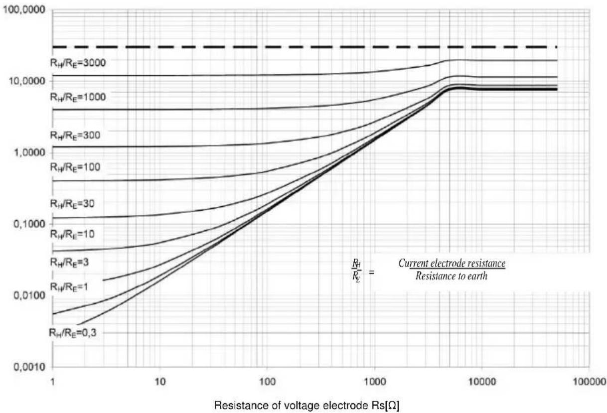
line
| Resistance of voltage electrode Rs[Ω] | R_H/R_E = 0.3 | R_H/R_E = 1 | R_H/R_E = 3 | R_H/R_E = 10 | R_H/R_E = 30 | R_H/R_E = 100 | R_H/R_E = 300 | R_H/R_E = 1000 | R_H/R_E = 3000 | | -------------------------------------- | ------------- | ----------- | ----------- | ------------ | ------------ | ------------- | ------------- | -------------- | -------------- | | 1 | ~0.001 | ~0.01 | ~0.1 | ~1 | ~10 | ~100 | ~1000 | ~10000 | ~10000 | | 10 | ~0.01 | ~0.1 | ~1 | ~1 | ~10 | ~100 | ~1000 | ~10000 | ~10000 | | 100 | ~0.1 | ~1 | ~10 | ~1 | ~10 | ~100 | ~1000 | ~10000 | ~10000 | | 1000 | ~1 | ~10 | ~10 | ~1 | ~10 | ~100 | ~1000 | ~10000 | ~10000 | | 10000 | ~1 | ~10 | ~10 | ~1 | ~10 | ~100 | ~1000 | ~10000 | ~10000 | | 100000 | ~1 | ~10 | ~10 | ~1 | ~10 | ~100 | ~1000 | ~10000 | ~10000 |10.3.5 Additional uncertainties according to IEC 61557-6 (RCD)
I_A, t_A, U_B
| Significant parameter | Designation | Additional uncertainty |
| Position | E_1 | 0% |
| Supply voltage | E_2 | 0% (BAT is not lit) |
| Temperature 0...35°C | E_3 | 0% |
| Resistance of electrodes | E_5 | 0% |
| Network voltage 85%..110% | E_8 | 0% |
11 Positions of the meter's cover
The movable cover enables using the meter in various positions.
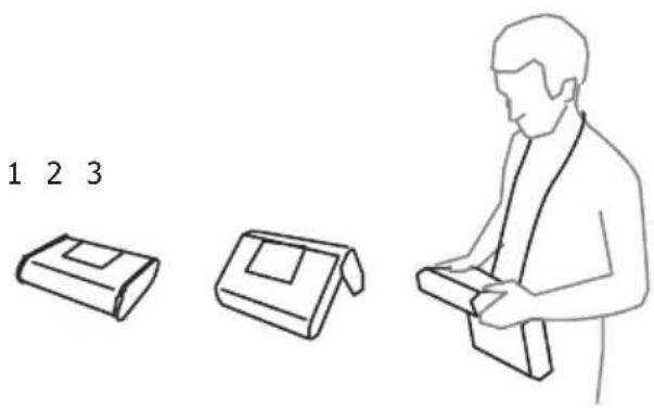
1 – Cover as the bottom of the meter
2 – Cover used as a support
3 – Cover in the position that enables convenient use of the meter suspended on the neck by means of hanging straps
12 Manufacturer
The manufacturer of the device, which also provides guarantee and post-guarantee service is the following company:
SONEL S.A.
Wokulskiego 11
58-100 Świdnica
Poland
tel. +48 74 884 10 53 (Customer Service)
e-mail: customerservice@sonel.com
web page: www.sonel.com
Attention:
Service repairs must be realised solely by the manufacturer.
NOTES
WARNING AND GENERAL DATA DISPLAYED BY THE METER
WARNING!
The MPI-520 meter is designed for operation at rated phase voltages of 110V, 115V, 127V, 220V, 230V, and 240V as well as at phase-to-phase voltages of 190V, 200V, 220V, 380V, 400V, and 415V.
Any voltage that exceeds the admissible voltage must not be applied to any measuring terminals. Failure to observe this warning may result in damage to the device and cause danger to users.
| L-N! | U_L-N voltage is incompatible with measuring procedure. |
| L-PE! | U_L-PE voltage is incompatible with measuring procedure. |
| N-PE! | U_N-PE voltage exceeds the admissible level of 50V. |
| Phase connected to N terminal instead of L terminal. | |
 | Exceeded temperature. |
| Dusn1 | Mains frequency exceeds the 45 ... 65Hz range. |
| Error measure | Cannot display correct result. |
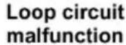 | Send meter to service centre. |
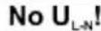 | No U_L-N voltage prior to the main measurement. |
| Dusn2 | Measurement has been stopped with ESC key. |
conti 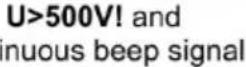 | Voltage on measuring terminals exceeds 500V prior to the measurement. |
conti 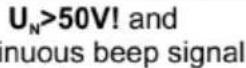 | Voltage on measuring terminals exceeds 50V; measurement of R_E is locked. |
| [H472] | Voltage on measuring terminals exceeds 24V but does not reach 50V; measurement of R_E is locked. |
| [644Z] | Uncertainty of R_E measurement from electrode resistance >30%. |
| [273D] | Discontinuity in R_E measuring circuit or probe resistance exceeds 60kΩ. |
| and continuous beep signal | Voltage between touch electrode and PE exceeds the admissible U_L threshold value. |
| Dusn3 | RCD failure if seen at the right-hand side of the result. |
| [K274] | Presence of measuring voltage on meter terminals at measurement of R_ISO . |
| Dusn4 | Excessive signal interferences. Measurement may be distorted by additional variance. |
| Dusn5 | Initiation of current constraints at measurements of R_ISO . |
| [CKYW] | Unsuitable accessories connected to measuring socket ( R_ISO ). |
 | WS-03 or WS-04 wire connected to three-conductor measurements of R_ISO . |
 | Condition of batteries or accumulators:Batteries or accumulators are chargedBatteries or accumulators are dischargedBatteries or accumulators are out of use |
 | Batteries or accumulators are out of use.Install new batteries or charge the accumulators. |
SONEL S.A.
Wokulskiego 11
58-100 Świdnica
Poland
Customer Service
tel. +48 74 884 10 53
e-mail: customerservice@sonel.com
www.sonel.com
- USER MANUAL
- METER FOR ELECTRICAL INSTALLATION PARAMETERS
- METER FOR ELECTRICAL INSTALLATION PARAMETERS MPI-520
- CONTENTS
- Safety 5
- Menu....6
- Measurements....12
- Memory of measurement result data....42
- Data transmission....47
- Power supply....49
- Cleaning and maintenance ....52
- Storage....53
- Dismantling and utilisation....53
- Technical data....53
- Positions of the meter's cover 63
- Manufacturer 63
- Safety
- ATTENTION!
- Attention:
- Note:
- Menu
- Wireless transmission
- Settings of measurements
- Network voltage and frequency
- Main result of short circuit loop impedance measurement
- Measurement settings
- Cell autoincrementing
- Settings of the meter
- LCD contrast
- LCD backlight
- Auto-OFF settings
- Date and time
- Factory (default) settings
- Program update
- Language selection
- Information about manufacturer
- Measurements
- Remarks:
- Measurement of alternating voltage and frequency
- Checking correctness of PE (protective earth) connections
- WARNING:
- Measurement of current, active power, reactive power, apparent power and cosφ coefficient
- Measurement of short circuit loop parameters
- Measurement of short circuit loop parameters in L-N and L-L circuit
- Additional information displayed by the meter
- Measurement of short circuit loop parameters in L-PE circuit
- Measurement of short circuit loop impedance in L-PE circuit protected with residual current device (RCD)
- Prospective short-circuit current
- Measurement of resistance-to-earth
- ①
- ②
- ③
- ④
- ⑤
- Measurement of RCD parameters
- Measurement of RCD disconnection current
- Remark:
- Measurement of RCD disconnection time
- Automatic measurement of RCD parameters
- Measurement of insulation resistance
- Double-lead measurement
- Measurements with AutolISO-1000c adapter
- Measurements by means of leads with UNI-Schuko outlet plug (WS-03 and WS-04)
- Low-voltage measurement of resistance
- Measurement of resistance of protective conductors and equipotential bonding with ±200 mA current
- Measurement of resistance
- Calibration of test leads
- Checking sequence of phases
- Memory of measurement result data
- Recording measurement result data in the memory
- Viewing memory data
- Deleting memory data
- Data transmission
- Computer connection accessories
- Data transmission with USB joint
- Data transmission with OR-1 radio module
- Power supply
- Monitoring of the power supply voltage
- Replacement of batteries (accumulators)
- NOTE!
- Charging of accumulators
- General principles regarding using Ni-MH accumulators
- Cleaning and maintenance
- Storage
- Dismantling and utilisation
- Technical data
- Basic data
- Indications of short-circuit current I_K
- Measurement of short circuit loop impedance Z_L-PE RCD (without triggering of RCD)
- Measurement of short circuit loop impedance Z_6
- Measurement of parameters of RCD
- RCD trigger and response time test t_A (for t_A mode).
- Measurement of RCD disconnection current I_A for differential unidirectional pulsed current and unidirectional pulsed current with 6mA direct current offset
- Measurement of RCD disconnection current I_A for differential direct current
- Measurement of resistance-to-earth R_E
- Measurement of interference voltages
- Low-voltage measurement of continuity of circuit and resistance
- Measurement of continuity of protective conductors and equipotential bondings with ±200 mA current
- Measurement of insulation resistance
- Phase sequence
- Other technical data
- Additional data
- Additional uncertainties according to IEC 61557-2 (R _ISO )
- Additional uncertainties according to IEC 61557-3 (Z)
- Additional uncertainties according to IEC 61557-4 (R ±200 mA)
- Additional uncertainties according to IEC 61557-5 (R _E )
- Additional uncertainties according to IEC 61557-6 (RCD)
- Positions of the meter's cover
- Manufacturer
- SONEL S.A.
- WARNING AND GENERAL DATA DISPLAYED BY THE METER
- WARNING!
Brand : Sonel
Model : MPI-520
Category : Measurement