MRU-11 - Measurement Sonel - Free user manual and instructions
Find the device manual for free MRU-11 Sonel in PDF.


| Product Type | Earth Resistance Meter |
| Model | MRU-11 |
| Brand | Sonel |
| Dimensions | 221 x 102 x 62 mm (without test leads) |
| Weight | 660 g (with batteries) |
| Power Supply | 4 x AA alkaline or NiMH rechargeable batteries |
| Measurement Methods | 2-pole, 3-pole, 4-pole (Wenner) earth resistance; soil resistivity |
| Measuring Range (Earth Resistance) | 0.01 Ω to 9999 Ω (depending on method) |
| Soil Resistivity Range | 0.00 Ωm to 999 kΩm (with distance L 1-50 m or 1-150 ft) |
| Interference Voltage Measurement | 0 to 100 V RMS, accuracy ±(10% + 1 digit) |
| Test Voltage | 25 V or 50 V (selectable) |
| Test Frequency | 125 Hz (50 Hz networks) / 150 Hz (60 Hz networks) |
| Measuring Current | >20 mA (short circuit) |
| Auto-Off Time | 300 s, 600 s, 900 s, or off (selectable) |
| Ingress Protection | IP67 |
| Safety Category | CAT III 300 V (up to 2000 m), double insulation |
| Operating Temperature | -10°C to +50°C |
| Storage Temperature | -20°C to +60°C |
| Display | LCD with backlight |
| Battery Monitoring | Symbol indication; low battery warning |
| Maintenance | Clean with damp cloth; no user-serviceable parts inside |
| Standards Met | EN 61010-1, EN 61557-1/-5, EN 61326-1/-2-2 |
| Accessories Included | Test leads, auxiliary electrodes, reels (per package) |
| Warranty | Manufacturer guarantee (standard terms) |
Frequently Asked Questions - MRU-11 Sonel
User questions about MRU-11 Sonel
0 question about this device. Answer the ones you know or ask your own.
Ask a new question about this device
Download the instructions for your Measurement in PDF format for free! Find your manual MRU-11 - Sonel and take your electronic device back in hand. On this page are published all the documents necessary for the use of your device. MRU-11 by Sonel.
USER MANUAL MRU-11 Sonel
natural_image
Line drawing of a handheld electronic device with control buttons and display screen (no text or symbols)USER MANUAL
USER MANUAL
EARTH RESISTANCE METER MRU-11
CE
SONEL S.A.
Wokulskiego 11
58-100 Świdnica
Poland
Version 1.07 11.07.2023
The MRU-11 meter is a modern, easy and safe measuring device. Please acquaint yourself with this manual in order to avoid measuring errors and prevent possible problems in operation of the meter.
CONTENTS
1 Safety 4
2 Turning the meter ON and activating screen backlight 5
3 Meter configuration 6
4 Measurements....9
4.1 Measurement of interference voltages DC + AC 9
4.2 Measurement of earth resistances with 3-pole method (R E 3P)....10
4.3 Measurement of earth resistances with 4-lead method (R E 4P)....14
4.4 Measurement of earth resistances with 2-pole method (R E2P).... 18
4.5 Soil resistivity measurement (ρ) 20
5 Power supply....23
5.1 Monitoring the power supply voltage.... 23
5.2 Replacing (rechargeable) batteries 24
5.3 General principles regarding using Ni-MH rechargeable batteries 25
6 Cleaning and maintenance 25
7 Storage....25
8 Dismantling and disposal 26
9 Technical data....26
9.1 Basic data 26
9.2 Other technical data....27
9.3 Additional data 28
9.3.1 Influence of serial interference voltage on the resistance measurements for function R_E3P , R_E4P , .....28
9.3.2 Influence of the auxiliary electrodes on earth resistance measurements for function R_E3P , R_E4P , .....28
9.3.3 Additional uncertainties according to IEC 61557-5 (BP)....28
10 Manufacturer 29
1 Safety
The following international symbols are used in the Analyzer and in this manual:
 | Warning;See explanation in the manual |  | Dual insulation(Protection class II) |
 | Do not dispose of with other household waste |  | Declaration of Conformity with EU directives (Conformité Européenne) |
MRU-11 meter is designed for measuring parameters important for safety of electrical installations. Therefore, in order to provide conditions for correct operation and accuracy of obtained results, the following recommendations must be observed:
- Before you proceed to operate the meter, acquaint yourself thoroughly with the present manual and observe the safety regulations and specifications provided by the producer.
- MRU-11 meter is designed to measure earth resistance values. Any application that differs from those specified in the present manual may result in a damage to the device and constitute a source of danger for the user.
- The meter must be operated solely by appropriately qualified personnel members holding required certificates for carrying measurements in electric installations. Unauthorized use of the meter may result in its damage and may be a source of serious hazard to the user.
- Using this manual does not exclude the need to comply with occupational health and safety regulations and with other relevant fire regulations required during the performance of a particular type of work. Before starting the work with the device in special environments, e.g. potentially fire-risk/explosive environment, it is necessary to consult it with the person responsible for health and safety.
- It is unacceptable to operate the device when:
⇒ a damaged meter which is completely or partially out of order,
⇒ a meter with damaged insulation,
⇒ a meter stored for an excessive period of time in disadvantageous conditions (e.g. excessive humidity). If the meter has been transferred from a cool to a warm environment with a high level of relative humidity, do not start measurements until the meter is warmed up to the ambient temperature (approximately 30 minutes).
- Before measurement make sure that test leads are connected to appropriate measuring terminals.
- Do not power the meter from sources other than those listed in this manual.
- The inputs of the meter are protected electronically against overload e.g. due to having been connected to a live circuit, for all combinations of inputs - up to 276 V for 30 seconds.
- Factory calibration does not include the resistance of the test leads. The result displayed by the meter is a sum of the resistance of the measured object and the resistance of leads.
- The device meets the requirements of standards EN 61010-1 and EN 61557-1, -5.

Due to continuous product development, the manufacturer reserves the right to introduce changes to the functionality, appearance, accessories and technical data of the meter. Due to continuous development of the meter's software, the actual appearance of the display, in case of some of the functions, may slightly differ from the display presented in this operating manual.
2 Turning the meter ON and activating screen backlight
①
To turn ON the meter, press ON/OFF button.
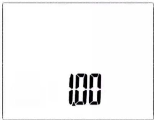
The screen of the device will activate its all segments (self-test), and then it will briefly show the software version.
②
When the meter is ON, a short press on ON/OFF button will turn ON and then OFF the screen backlight;
③
To turn OFF the device, press and hold ON/OFF button for approx. 2 seconds.
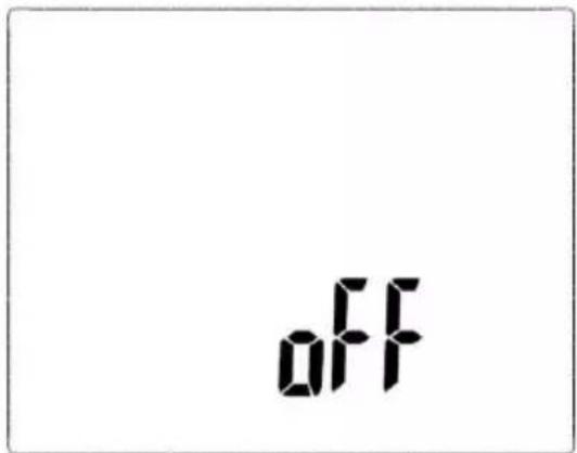
A screen indicating shutting off the device is shown briefly.
3 Meter configuration
①
Turn on the meter by pressing and holding DOWN button and pressing ON/OFF button.
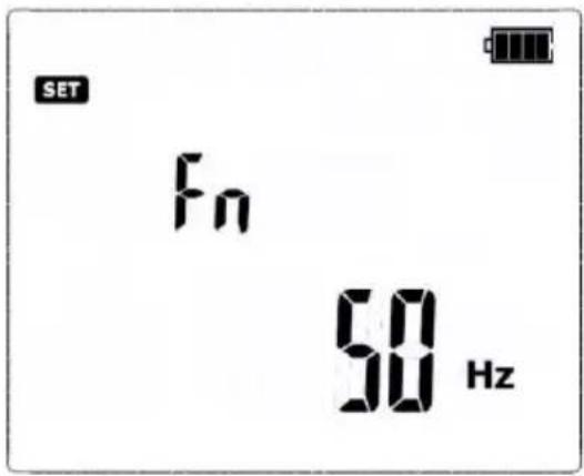
After switching the meter ON, a screen is shown with network frequency settings Fn.
②
When the Fn screen is displayed, use UP and DOWN buttons to set the network frequency of 50 Hz or 60 Hz (default: 50 Hz).
③
Short press START button to accept the selected value.
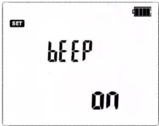
You will enter the screen with settings of audio messages - bEEP.
④
Use UP and DOWN buttons to turn the audio messages ON (or OFF ( ) off
⑤
Short press START button to accept the selected option.
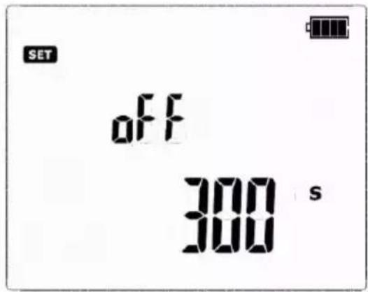
The screen of Auto-OFF time settings will be shown: oFF.
⑥
Use UP and DOWN buttons to set the auto-off time at 300 s, 600 s, 900 s or "-" (Auto-OFF inactive). Auto-OFF function is used to turn-off inactive meter after a preselected time, which is signalled by a beep.
⑦
Short press START button to accept the selected option.
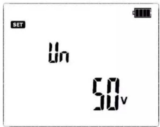
You will enter the screen with measuring voltage selection Un.
⑧
Use UP and DOWN buttons to set the measuring voltage at 25 V or 50 V. The measuring voltage set relates to all measurement functions in the meter.
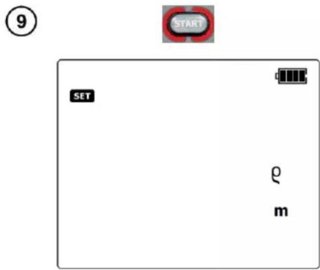
Short press START button to accept the selected option.
You will enter the screen with settings of units soil resistivity.

natural_image
Two circular buttons with white arrows, one numbered 10 (no text or symbols on buttons)Use UP and DOWN buttons to set the unit:
⇒ meters m or
⇒ feet ft.

Short press START button to accept the selected option.
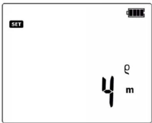
You will enter the screen with settings of distance between auxiliary electrodes.

Use UP and DOWN buttons to set the distance.
Short press START button to accept the selected option and return to the network frequency selection screen Fn.

Long press (> 2 s) START button to the introduced changes and proceed to the measurement screen RE3P.

Long press (> 2 s) ON/OFF button to turn off the meter without accepting the changes introduced at the current setting position.

Short press (> 2 s) ON/OFF button to enter the measurement screen R_E 3P without accepting the changes introduced at the current setting position.
4 Measurements

Earth resistance measurements significantly different from other measurements performed to assess the protection against electric shock. They require a thorough knowledge of the structure of earthing system, the phenomena occurring during the measurements and the skills of coping with severe outdoor conditions. Earthing system tests/measurements require adequate knowledge and curing equipment, which will be able to maximally facilitate these examinations.
4.1 Measurement of interference voltages DC + AC
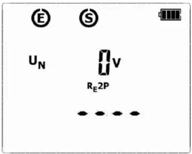
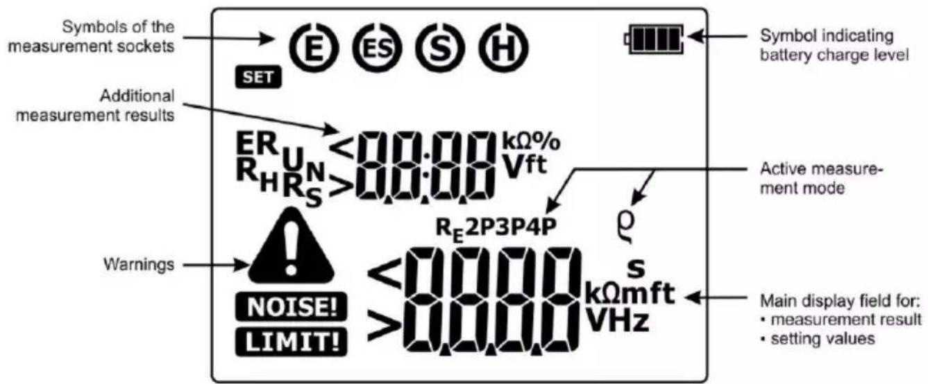
In measuring functions, before START button is pressed, the meter monitors the measuring voltage at the terminals (between E socket and S / H sockets) and the interference voltage value is displayed on the screen.
Additional information displayed by the meter
U_N > 100V!, > 100V and a continuous beep ,
NOISE! and

Voltage at test terminals is higher than 100 V, the measurement is blocked.
UN xxV!, >40V and a continuous
beep
NOISE! and

Where xx is the value of interference voltage. Voltage at test terminals is higher than 40 V but lower than 100 V, the measurement is blocked.
UNxxV!, >24V, NOISE! and

Where xx is the value of interference voltage. Voltage at test terminals is higher than 24 V but lower than 40 V, the measurement is blocked.
NOISE!
The interference voltage is lower than 24 V, but with a high value - the measurement result may be affected by additional uncertainty.
4.2 Measurement of earth resistances with 3-pole method (R_E3P)

For earth resistance measurements, the most commonly used method is the 3-pole method, often called the potential drop method, or technical method. During the measurement, the voltage drop at the earthing is measured with current flowing through it, then the Ohm's law is used to calculate the resistance.
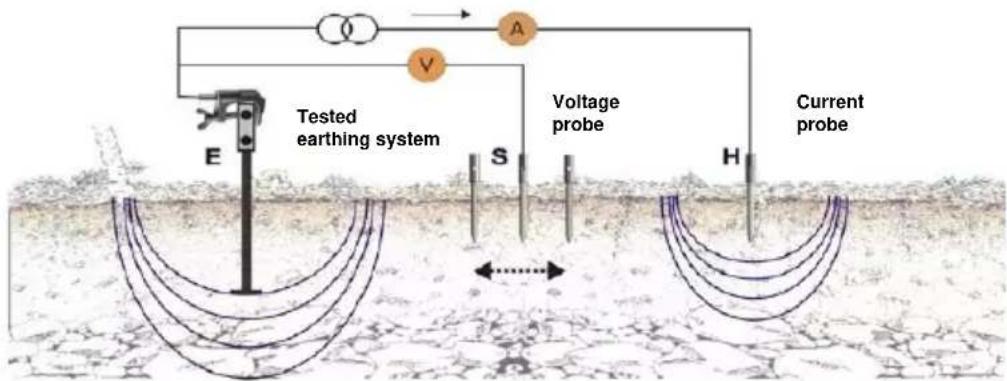
The scheme of measuring the earthing resistance with the 'technical method' is shown above. The figure shows the measurement of earthing resistance R E. To perform the measurement, use two additional auxiliary electrodes:
- H electrode (current electrode) to allow excitation of current flow in the circuit: tested earth electrode R_E meter H current electrode earth tested earth electrode;
- S electrode (voltage electrode) for measuring the voltage drop across the resistance of the measured earthing as a result of current flow.

Disconnect the tested earth electrode from the installation of the facility.
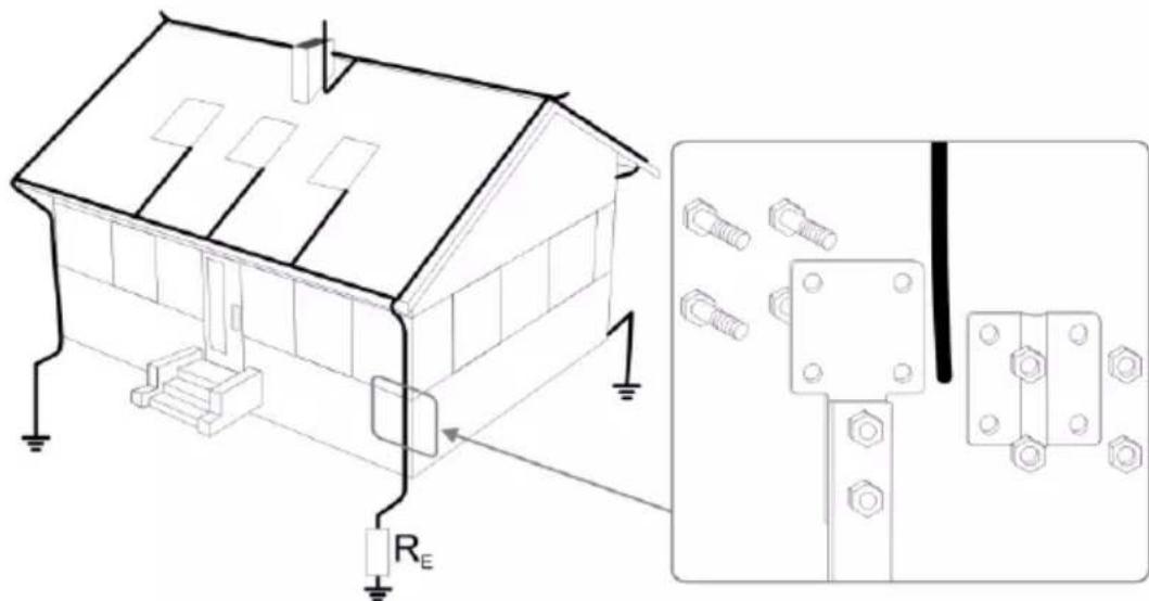
②
Turn on the meter using ON/OFF button.
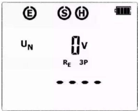
The meter enters the measurement function screen Re3P.
The meter is in the mode of measuring the interference voltage between the test terminals. The measuring voltage is compatible with the voltage selected when setting up the device.
③
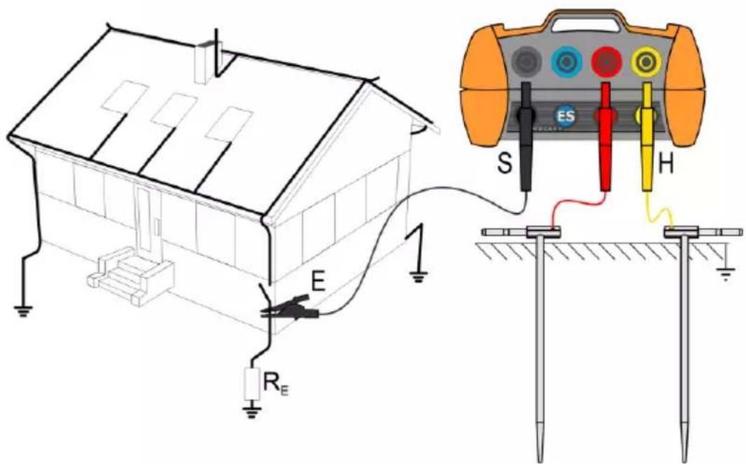
Test leads should be connected to the measurement terminals in the device, as shown above.
- The current electrode H (driven into earth) should be connected to H socket of the meter.
- The voltage electrode S (driven into earth) should be connected to S socket of the meter.
- The earth electrode being tested should be connected to E socket of the meter with the lead.
- The earth electrode being tested and the current electrode and the voltage electrode should be located in one line.
④
Press START.
The progress of the measurement is indicated by horizontal lines on the screen.
⑤
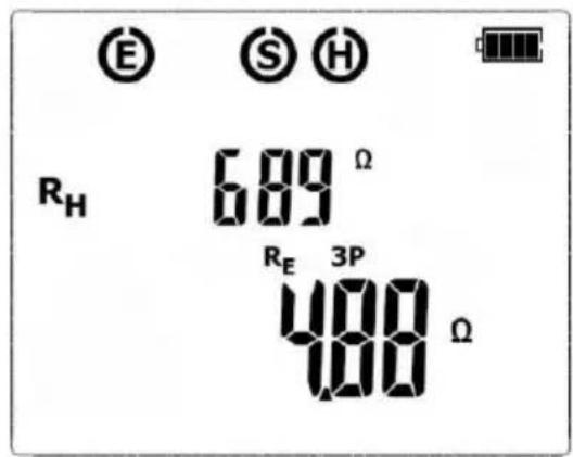
After completing the measurement, results are displayed for all the measurements carried-out: at the bottom of the screen, the main result is shown for R_E , whereas the upper part of the screen shows additional results for R_H . The result is displayed for 20 seconds. The result can be recalled by pressing UP button.
⑥
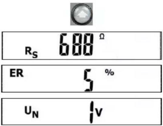
Use UP button to view the component results in the following order: R_H R_S ER U_N , where:
R_H – resistance of electrode H R_S – resistance of electrode S ER – additional uncertainty resulting from the electrode UN - interference voltage
⑦
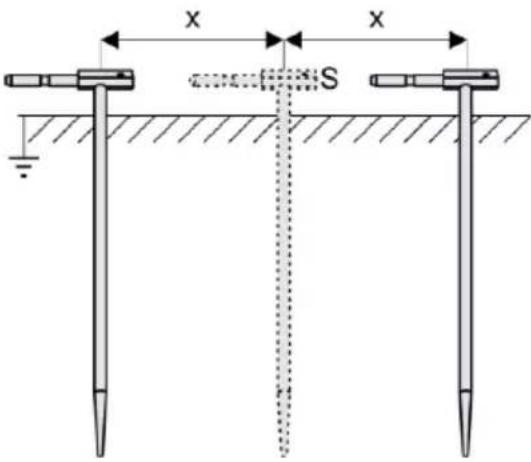
Repeat the measurements (steps 456) moving the voltage electrode a few meters - placing it farther and closer to the measured earth electrode. If R_E measurement results differ from one another by more than 3%, the distance of the current electrode from the earth electrode being tested should be considerably increased and the measurements should be repeated.

NOTE!
Measurement of resistance-to-earth may be carried out if voltage of interferences does not exceed 24 V. Voltage of interferences is measured up to the level of 100 V, but above 40 V it is signalled as dangerous. The meter must not be connected to voltages exceeding 100 V.

- Particular attention should be paid to quality of connection between the object being tested and the test lead – the contact area must be free from paint, rust, etc.
- If resistance of electrodes is too high, R_E earth electrode measurement will include an additional uncertainty. Particularly high uncertainty of measurement occurs when a small value of resistance-to-earth is measured with electrodes that have a weak contact with earth (such a situation occurs frequently when the earth electrode is well made and the upper soil layer is dry and slightly conductive). In such a case, the ratio of resistance of the electrodes to resistance of the tested earth electrode is very high and consequently, uncertainty of measurement that depends on this ratio is also very high. Then, you can make a calculations according to the formulas given in sec. 9.3 to estimate the influence of measurement conditions. You can improve the contact between the electrode and soil, for example, by dampening with water the place where the electrode is driven into earth, driving the probe into earth in a different place or using a 80 cm-long electrode. Check also the test leads for possible insulation damage and for corroded or loosened connection between the banana plug and the test lead. In majority of cases the achieved measurement accuracy is satisfactory. However, you should always be aware of the uncertainty included in the measurement.
Additional information displayed by the meter
| RE>9999 Ω | Measuring range is exceeded. |
| UN>100 V, >100 Vand a continuous beep ⬆,NOISE! and [IMAGE] | Voltage at test terminals is higher than 100 V, measurement is blocked. |
| UN xxV, >40 Vand a continuous beep ⬆,NOISE! and [IMAGE] | Where xx is the value of interference voltage. Voltage at test terminals is higher than 40 V, measurement is blocked. |
| UN xxV, >24 V,NOISE! and [IMAGE] | Where xx is the value of interference voltage. Voltage at test terminals is higher than 24 V but lower than 40 V, the measurement is blocked. |
| NOISE! | The interfering signal (noise signal) is too high - the measurement result may be affected by additional uncertainty. |
| LIMIT!and ER together with the value expressed in % | Measurement due to the resistance of the auxiliary electrodes >30%. (Measured values are used in calculation of uncertainty.) |
| LIMIT!and RH or Rs with the value of Ω | Resistance of auxiliary electrodes H and S, or one of them exceeds 19.9 kΩ, correct measurement is not possible. |
Flashing edges | Flashing edges of symbols: E or H or S, two or all three at the same time: disconnected one, two or three leads to the terminals, or the resistance of the auxiliary auxiliary electrode/s is outside the measuring range. |
4.3 Measurement of earth resistances with 4-lead method ( R_E4P )

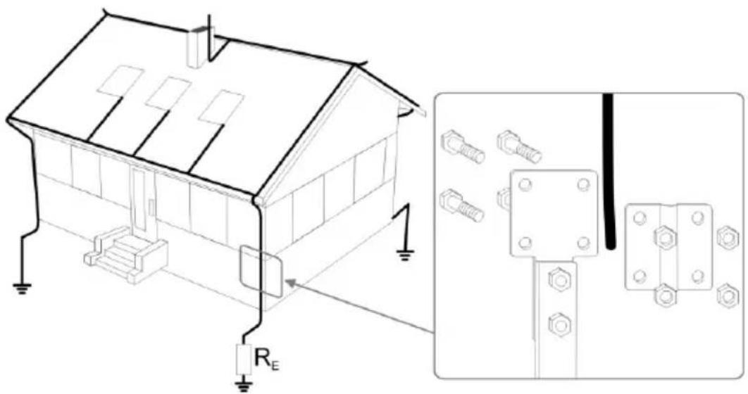
The four-lead method is recommended in the case of measurements of earth resistance of very low values. It permits to eliminate the influence of the test leads resistance over the result of the measurement. In order to evaluate the resistivity of the ground it is recommended to use the dedicated measurement function.
①
Disconnect the tested earth electrode from the installation of the facility.
②
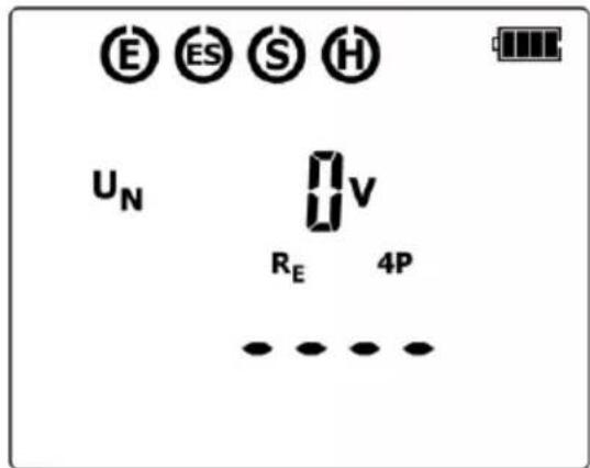
Turn on the meter using ON/OFF button.
Press DOWN button until the screen of Re4P measurement appears.
The meter is in the mode of measuring the interference voltage between the test terminals. The measuring voltage is compatible with the voltage selected when setting up the device.
③
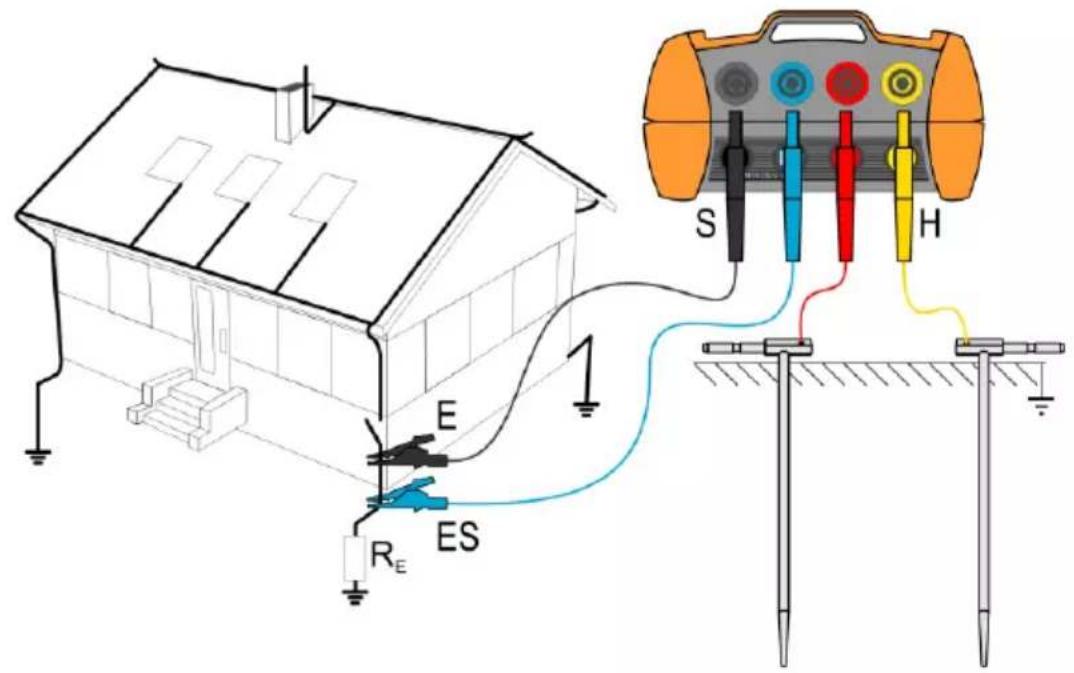
Test leads should be connected to the measurement terminals in the device, as shown above.
- Connect the current electrode driven into ground to the H socket of the meter.
- Connect the voltage electrode driven into ground to the S socket of the meter.
- Connect the tested earth electrode to the E socket of the meter.
- Connect the ES socket to the earth electrode In question below the E cable.
- The tested earth electrode as well as the current electrode and voltage electrode should be aligned.
④
Press START.
The progress of the measurement is indicated by horizontal lines on the screen.
⑤
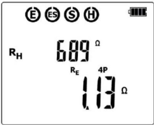
After completing the measurement, results are displayed for all the measurements carried-out: at the bottom of the screen, the main result is shown for R_E , whereas the upper part of the screen shows additional results for R_H . The result is displayed for 20 seconds. The result can be recalled by pressing UP button.
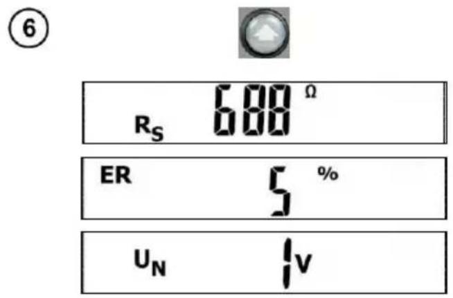
Use UP button to view the component results in the following order:
R_H R_S ER U_N , where:
RH – resistance of electrode H
Rs - resistance of electrode S
ER – additional uncertainty resulting from the electrodes
UN - interference voltage
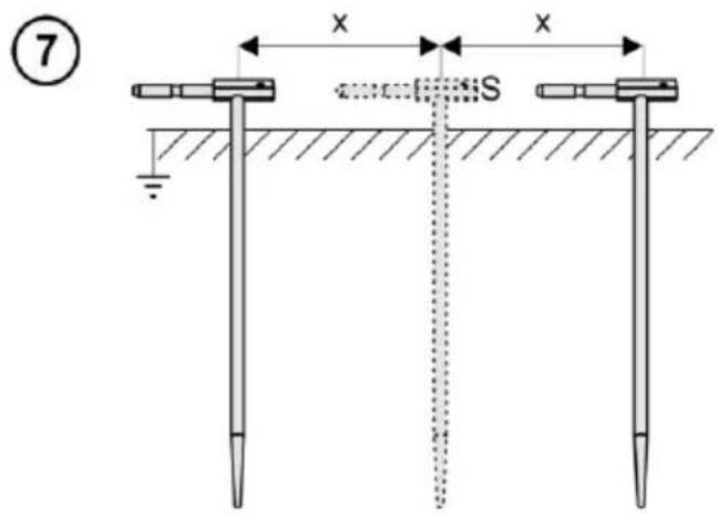
Repeat the measurements (steps) 456 moving the voltage electrode a few meters - placing it farther and closer to the measured earth electrode.
If RE measurement results differ from one another by more than 3%, the distance of the current electrode from the earth electrode being tested should be considerably increased and the measurements should be repeated.

NOTE!
Measurement of resistance-to-earth may be carried out if voltage of interferences does not exceed 24 V. Voltage of interferences is measured up to the level of 100 V, but above 40 V it is signalled as dangerous. The meter must not be connected to voltages exceeding 100 V.

- Particular attention should be paid to quality of connection between the object being tested and the test lead – the contact area must be free from paint, rust, etc.
- If resistance of electrodes is too high, R_E earth electrode measurement will include an additional uncertainty. Particularly high uncertainty of measurement occurs when a small value of resistance-to-earth is measured with electrodes that have a weak contact with earth (such a situation occurs frequently when the earth electrode is well made and the upper soil layer is dry and slightly conductive). In such a case, the ratio of resistance of the electrodes to resistance of the tested earth electrode is very high and consequently, uncertainty of measurement that depends on this ratio is also very high. Then, you can make a calculations according to the formulas given in sec. 9.3 to estimate the influence of measurement conditions. You can improve the contact between the electrode and soil, for example, by dampening with water the place where the electrode is driven into earth, driving the probe into earth in a different place or using a 80 cm-long electrode. Check also the test leads for possible insulation damage and for corroded or loosened connection between the banana plug and the test lead. In majority of cases the achieved measurement accuracy is satisfactory. However, you should always be aware of the uncertainty included in the measurement.
Additional information displayed by the meter
| RE>9999Ω | Measurement range exceeded. |
UN>100V, >100V and a continuous sonic signal←,NOISE! and  | The voltage on the measurement points exceeds 100 V, the measurement is blocked. |
UN xxV, >40V and a continuous sonic signal←,NOISE! and  | Where xx is the value of interfering voltage. The voltage on the measurement points exceeds 40 V, the measurement is blocked. |
UN xxV, >24V, NOISE! and  | Where xx is the value of interfering voltage. The voltage on the measurement points exceeds 24 V, but it's below 40 V, the measurement is blocked. |
| NOISE! | The value of the interfering signal is below 24 V, but it has too high value, so the result may be distorted by additional uncertainty. |
 and ER along with % value and ER along with % value | The uncertainty caused by resistance of the auxiliary electrodes >30%. (Uncertainties calculated on the basis of the measured values.) |
| LIMIT! and RH or Rs along with Ω value | The resistance of H and S electrodes, or one of them ex-ceeds 19.9 kΩ, the proper measurement is not possible. |
Flashing symbols:  | Flashing symbols E or H or S, or both of them, or all three at the same time, one or two or three test leads are dis-connected from the measurement sockets. |
4.4 Measurement of earth resistances with 2-pole method (R_E2P)

2-pole method may be also used for measuring earth resistance. When the earthing system is known and earthing is available with a known resistance value, the measurement result will be the sum of the earth resistances: measured and known.

Turn on the meter. After turning the meter ON, the screen with 3-pole method R3P is shown.


Press DOWN button until the screen of 2-pole method Re2P appears.
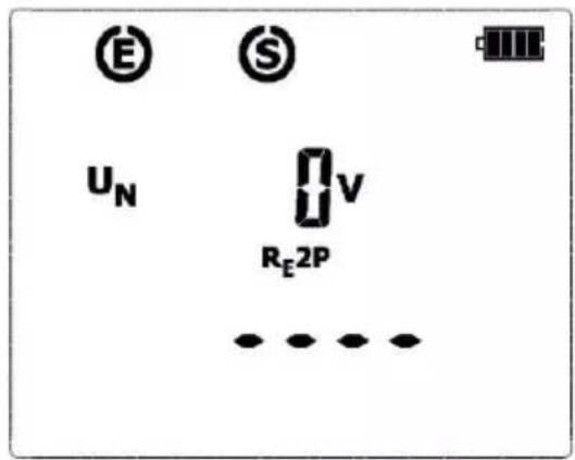
The meter is in the mode of measuring the interference voltage between the test terminals. The measuring voltage is compatible with the voltage selected when setting up the device.

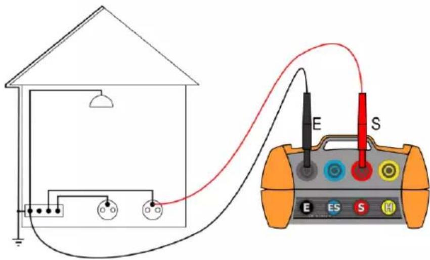
Test leads should be connected to the measurement terminals in the device, as shown above.


In order to start the measurement, press START button.

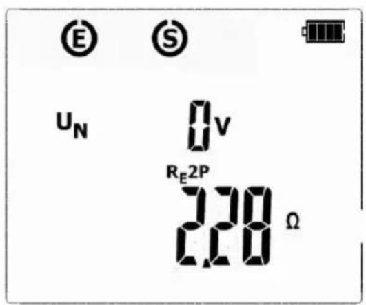
After the measurement, its result is shown: at the bottom of the screen, the main result is shown for RE2P, whereas the upper part of the screen shows the measured interference voltage UN. The result is displayed for 20 seconds. The result can be recalled by pressing UP button.
Additional information displayed by the meter
| R > 9999 Ω | Measuring range is exceeded. |
| UN>100 V, >100 V and a continuous beep ↔, NOISE! and | Voltage at test terminals is higher than 100 V, measurement is blocked. |
| UNxxV, >40 V and a continuous beep ↔, NOISE! and | Where xx is the value of interference voltage. Voltage at test terminals is higher than 40 V, measurement is blocked. |
| UNxxV, >24 V,NOISE! and | Where xx is the value of interference voltage. Voltage at test terminals is higher than 24 V but lower than 40 V, the measurement is blocked. |
| NOISE! | The interfering signal (noise signal) is below 24 V, but with a high value - the measurement result may be affected by additional uncertainty. |
4.5 Soil resistivity measurement (ρ)
For the purpose of earth resistivity measurements – which are used as a preliminary measure for the project of earthing systems or in geology - there is a separate function: earth resistivity measurements . The function is metrologically identical as the four-lead earth resistance measurement, but it includes an additional procedure of storing of the distance between the auxiliary electrodes. The result of the measurement is the resistance value which is calculated automatically in accordance with the following formula:
$$ \rho = 2 \pi L R _ {E} $$
which is used in the Wenner's measurement method. The method in question assumes equal distances between electrodes.
① Connect test leads according to the drawing.
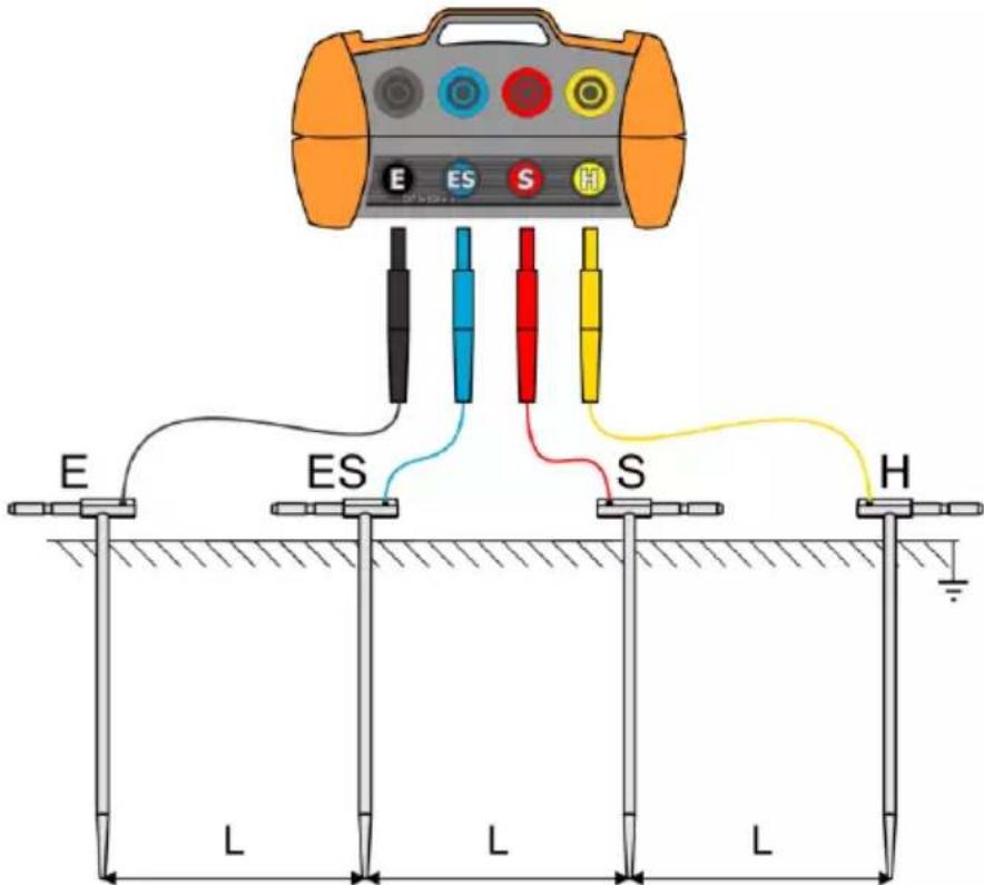
Connect the four aligned and equally spaced auxiliary electrodes, which are driven into the ground, to the meter, and do so in accordance with the diagram above.
- Connect the current electrode driven into ground to the H socket of the meter.
- Connect the voltage electrode driven into ground to the S socket of the meter.
- Connect the voltage electrode driven into ground to the ES socket of the meter.
- Connect the current electrode driven into ground to the E socket of the meter.
②
Turn on the meter using ON/OFF button.
Set measurement unit and distance L between electrodes according to sec. 3 steps ⑨. . ⑬
Press DOWN button until the screen of p measurement appears.
③
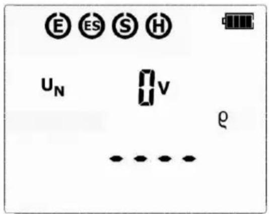
The meter is ready for measurement.
④
Press START to commence measurement.
⑤
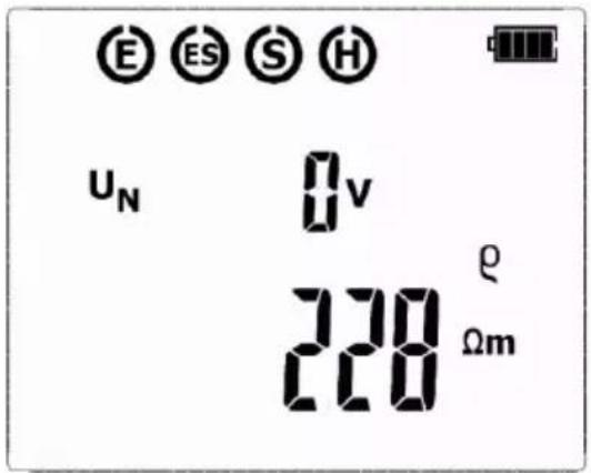
After finishing the measurement, read out the result. The results of all the measurements that have been carried out will be displayed on screen.
⑥
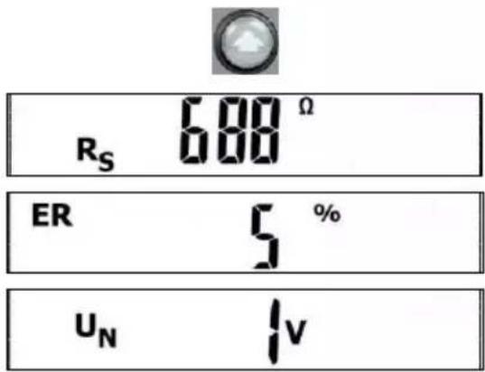
Use UP button to view the component results in the following order: R_H R_S ER U_N , where:
R_H – resistance of current electrode R_S - resistance of voltage electrode ER – additional uncertainty caused by the resistance of the electrodes U_N – interfering (noise) voltage

NOTE!
Earth resistivity measurement may be performed if the interference voltage does not exceed 24 V. The interference voltage is measured up to 100 V, but over 40 V is it signaled as hazardous. Do not connect the meter to a voltage exceeding 100 V.

- Calculations are based upon the assumption that the distances between the specific auxiliary electrodes are equal (the Wenner's method). If this is not the case the earthing resistance measurement must be carried out by means of the four-pole method and calculations must be performed individually.
- Pay particular attention to the quality of the connection of the tested object with the
test leads – the contact area must be cleaned of paint, rust, etc.
- If resistance of electrodes is too high, R_E earth electrode measurement will include an additional uncertainty. Particularly high uncertainty of measurement occurs when a small value of resistance-to-earth is measured with electrodes that have a weak contact with earth (such a situation occurs frequently when the earth electrode is well made and the upper soil layer is dry and slightly conductive). In such a case, the ratio of resistance of the electrodes to resistance of the tested earth electrode is very high and consequently, uncertainty of measurement that depends on this ratio is also very high. Then, you can make a calculations according to the formulas given in sec. 9.3 to estimate the influence of measurement conditions. You can improve the contact between the electrode and soil, for example, by dampening with water the place where the electrode is driven into earth, driving the probe into earth in a different place or using a 80 cm-long electrode. Check also the test leads for possible insulation damage and for corroded or loosened connection between the banana plug and the test lead. In majority of cases the achieved measurement accuracy is satisfactory. However, you should always be aware of the uncertainty included in the measurement.
Additional information displayed by the meter
| >xxxk m or >xxxk ft | Measurement range exceeded, where xxx is maximum value that can be measured for the selected settings. |
| U_N >100V, >100V and a continuous sonic signal ,NOISE! and [IMAGE] | The voltage on the measurement points exceeds 100 V, the measurement is blocked. |
| U_NxxV, >40V and a continuous sonic signal ,NOISE! and [IMAGE] | Where xx is the value of interfering voltage. The voltage on the measurement points exceeds 40 V, the measurement is blocked. |
| U_NxxV, >24V, NOISE! and | Where xx is the value of interfering voltage. The voltage on the measurement points exceeds 24 V, but it's below 40 V, the measurement is blocked. |
| NOISE! | The value of the interfering signal is below 24 V, but it has too high value, so the result may be distorted by additional uncertainty. |
| LIMIT!and ER along with % value | The uncertainty caused by resistance of the auxiliary electrodes >30%. (Uncertainties calculated on the basis of the measured values.) |
| LIMIT!and RH or Rs along with Ω value | The resistance of H and S electrodes, or one of them ex-ceeds 19.9 kΩ, the proper measurement is not possible. |
Flashing symbols: | Flashing symbols E or ES or H or S, or two of them, or three, or all of them at the same time – one or two or three or four test leads are disconnected from the measurement sockets. |
5 Power supply

Before the measurements, make sure that the status of the batteries or rechargeable batteries meter is sufficient for performing tasks related to the operation of the device.
5.1 Monitoring the power supply voltage
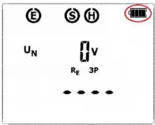
The charge level of the batteries or rechargeable batteries is indicated by the symbol in the right upper corner of the display on a current basis:
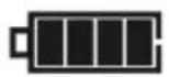
When all segments of the battery symbol are lit, it means that the batteries/rechargeable batteries are fully charged.
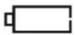
When all segments of the battery symbol are dark, it means that the batteries/rechargeable batteries are discharged and must be replaced.
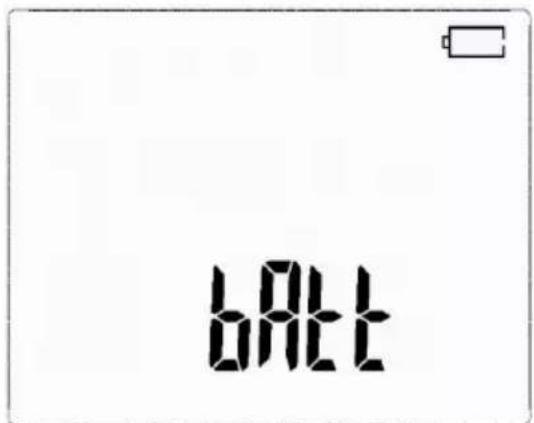
Message bAtt indicates that batteries/rechargeable batteries are totally discharged, all measurements are blocked. The meter switches off automatically after 5 sec.
5.2 Replacing (rechargeable) batteries
MRU-11 is powered by four AA alkaline LR6 batteries or rechargeable batteries of NiMH type. The (rechargeable) batteries are placed in the compartment at the bottom of the enclosure. The device is not equipped with an internal battery charger. Rechargeable batteries must be recharged in an external charger.

NOTE!
Do not power the meter from sources other than those listed in this manual. Before replacing the (rechargeable) batteries, disconnect the test leads from the meter.
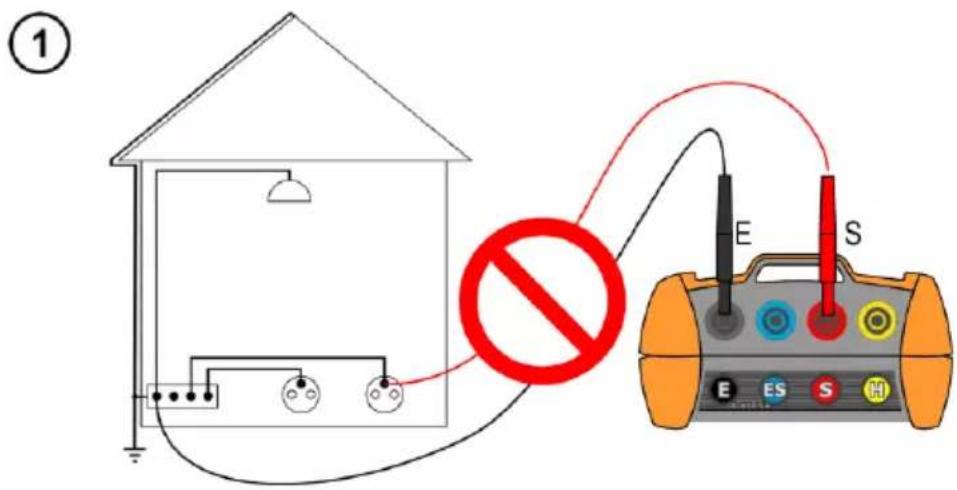
Disconnect the unit from the object!
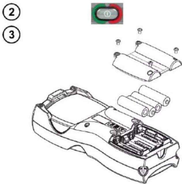
Turn off the device using ON/OFF button.
Remove the screws that secure the battery cover at the bottom of the compartment(4 pcs),
Remove all batteries (rechargeable batteries). Observe the correct polarity when inserting new batteries/rechargeable batteries.
Place and tighten the battery compartment cover.

NOTE!
Reverse polarity will not damage the meter or the batteries, but the meter will not work. Have the meter serviced in case of battery leakage inside the compartment.
5.3 General principles regarding using Ni-MH rechargeable batteries
- Store the he rechargeable batteries (the meter) in a dry, cool and well ventilated place and protect them from direct sunlight. The temperature of the environment in the case of prolonged storage should not exceed 30^ C. If the rechargeable batteries are stored for a long time in a high temperature, then the occurring chemical processes may reduce their lifetime.
- Rechargeable batteries NiMH usually lasts for 500-1000 charging cycles. The rechargeable batteries reach their maximum capacity after being formatted (2-3 charge and discharge cycles). The most important factor which influences the lifetime of rechargeable batteries is the level of their discharge. The deeper the discharge level of the batteries, the shorter their lifetime.
- The memory effect is limited in the case of NiMH batteries. These batteries may be charged at any point with no serious consequences. However, it is recommended to discharge them completely every few cycles.
- During storage of Ni-MH rechargeable batteries they are discharged at the rate of approximately 20% per month. Keeping rechargeable batteries at high temperatures may accelerate this process even 100%. In order to prevent excessive discharge of rechargeable batteries, after which it would be necessary to format them, it is recommended to charge them from time to time (even if they are not used).
- Modern fast chargers detect both too low and too high temperature of the battery pack and react to the situation adequately. Too low temperature should prevent starting the process of charging, which might irreparably damage rechargeable batteries. An increase of the temperature of the rechargeable batteries is a signal to stop charging and is a typical phenomenon. However charging at a high ambient temperature apart from reducing batteries' lifetime causes an accelerated increase of their temperature and the result is that the batteries are not charged to their full capacity.
- Please note that when the batteries are charged with a fast-charger they are charged only to approx. 80% of their capacity - better results can be achieved by continuing charging: the charger enters trickle-charging mode and during the next few hours batteries are charged to their full capacity.
- Do not charge or use the batteries in extreme temperatures. Extreme temperatures reduce the lifetime of batteries and rechargeable batteries. Avoid placing devices powered by rechargeable batteries in very hot environments. The nominal working temperature must be absolutely observed.
6 Cleaning and maintenance

NOTE!
Use only the maintenance methods specified by the manufacturer in this manual.
The casing of the meter may be cleaned with a soft, damp cloth using all-purpose detergents. Do not use any solvents or cleaning agents which might scratch the casing (powders, pastes, etc.).
Clean the auxiliary electrode with water and dry it. Before the probe is stored for a prolonged period of time it is recommended to grease it with any machine lubricant.
The reels and test leads should be cleaned with water and detergents, and then dried.
The electronic system of the meter does not require maintenance.
7 Storage
In the case of storage of the device, the following recommendations must be observed:
- Disconnect all the test leads from the meter.
- Clean the meter and all its accessories thoroughly.
• Wind the long test leads onto the reels. - If meter is to be stored for a prolonged period of time, the batteries must be removed from the device.
- In order to prevent a total discharge of the battery pack in the case of a prolonged storage, charge it from time to time.
8 Dismantling and disposal
Worn-out electric and electronic equipment should be gathered selectively, i.e. it must not be placed with waste of another kind.
Worn-out electronic equipment should be sent to a collection point in accordance with the law of waste electrical and electronic equipment.
Before the equipment is sent to a collection point, do not dismantle any elements.
Observe local regulations concerning disposal of packages, waste batteries and accumulators.
9 Technical data
- The specified accuracy relates to the meter terminals.
- The abbreviation „m.v.” in the accuracy definition means the measured value.
9.1 Basic data
Measurement of interference voltage U_N (RMS)
| Range | Resolution | Accuracy |
| 0...100 V | 1 V | ±(10% m.v. + 1 digit) |
• Measurement for f_N 45...65 Hz.
- The frequency of measurement - at least 2 measurements / sec.
Measurement of earth resistances - 2-pole method (R_E2P)
| Range | Resolution | Accuracy |
| 0.01 Ω ... 19.99 Ω | 0.01 Ω | ±(3% m.v. + 3 digits) |
| 20.0 Ω...199.9 Ω | 0.1 Ω | |
| 200 Ω...1999 Ω | 1 Ω | ±5% |
| 2000 Ω...9999 Ω | 1 Ω | ±8% |
- Measuring current at the short circuit of >20mA .
- Measuring frequency of 125 Hz or 150 Hz.
- Selected test voltage: 25 V or 50 V.
- Maximum interference voltage for the R_E measurement is 24 V.
Measurement of earth resistances - 3-pole method (RE3P), 4-wire method (RE4P)
Measurement method: 3-pole, conforming to EN 61557-5.
Measurement range according to EN 61557-5: 0.53 Ω...9999 Ω for Un = 50 V.
| Range | Resolution | Accuracy |
| 0.00 Ω...19.99 Ω | 0.01 Ω | ±(3% m.v. + 3 digits) |
| 20.0 Ω...199.9 Ω | 0.1 Ω | |
| 200 Ω...1999 Ω | 1 Ω | ±5% |
| 2000 Ω...9999 Ω | 1 Ω | ±8% |
- Measuring current at the short circuit of >20mA .
- Measuring frequency of 125 Hz or 150 Hz.
- Selected test voltage: 25 V or 50 V.
- Maximum interference voltage for the R_E measurement is 24 V.
Ground resistivity measurements
The measurement method: Wenner's, = 2 LR_E
| Range | Resolution | Accuracy |
| 0,00..9,99 Ωm | 0,01 Ωm | Depends on the accuracy of the R 4P measurement but not less than ±1 digit. |
| 10,0..99,9 Ωm | 0,1 Ωm | |
| 100..999 Ωm | 1 Ωm | |
| 1,00..9,99 kΩm | 0,01 kΩm | |
| 10,0..99,9 kΩm | 0,1 kΩm | |
| 100..999 kΩm | 1 kΩm |
• distance between auxiliary electrodes (L): 1...50 m or 1...150 ft
Measurement of resistance of auxiliary electrodes R_H and R_S
| Range | Resolution | Accuracy |
| 0...999 Ω | 1 Ω | ±(5% + 8 digits) |
| 1.00...9.99 kΩ | 0.01 kΩ | |
| 10.0...19.9 kΩ | 0.1 kΩ |
9.2 Other technical data
a) type of insulation acc. to EN 61010-1 and IEC 61557.....double
b) measurement category (for 2000 m a.s.l.) acc. to EN 61010-1....III 300 V
c) degree of housing protection acc. to EN 60529 IP67
d) maximum interference of AC + DC voltages, for the measurement .....24 V
e) maximum measured voltage of interferences ....100 V
f) measuring current frequency 125 Hz for 50 Hz networks 150 Hz for 60 Hz networks
g) measuring voltage for R_E2P , R_E3P , R_E4P ....25 V or 50 V
h) measuring current (short circuit) for R E2P, RE3P, RE4P....>20 mA
i) measurement range according to EN 61557-5: 0.53 Ω...9999 Ω for Un = 50 V
j) maximum resistance of auxiliary electrodes 20 kΩ
k) meter power supply ....4 x AA alkaline battery ....or 4 x AA NiMH rechargeable battery
I) number of measurements for R E 3P ....>3000
.... (R E =10 Ω, R H =R S =100 Ω, 25 V 50 Hz, 2 measurements/minute)
m) time of performing the resistance measurement with 2-pole method ....<4 s
n) time of performing the resistance measurement with 3-pole method ....<8 s
o) time of performing the resistance measurement with 4-lead method ....<8 s
p) dimensions 221 x 102 x 62 mm (without test leads)
q) weight of the meter with batteries 660 g
r) operating temperature....-10°C..+50°C
s) reference temperature....23 ± 2°C
t) storage temperature....-20..+60°C
u) relative humidity 20.90%
v) nominal relative humidity 40.60%
w) altitude (above sea level) .... ≤2000 m*
x) quality standard ......design and manufacturing are ISO 9001 compliant
y) measurement method ...... technical, conforming to EN 61557-5
z) the device meets the EMC requirements according to: ...... EN 61326-1 and EN 61326-2-2
NOTE
\* Information about the use of meter at altitude from 2000 m to 5000 m
As for voltage inputs E, ES, S, H the instrument is to be considered downgraded to measurement category CAT III 150 V to ground (max 150 V between inputs) or CAT IV 100 V to ground (max 100 V between inputs). Markings and symbols indicated on the instrument are to be considered valid when using it at altitude lower than 2000 m.
9.3 Additional data
Data on additional uncertainties are useful mainly when the meter is used in non-standard conditions and for metrological laboratories for the purpose of calibration.
9.3.1 Influence of serial interference voltage on the resistance measurements for function RE3P, RE4P, ρ
| R_E | U_N | Additional uncertainty [Ω] |
| 0.00 ... 10.00 Ω | 25 V | ±(0.001 R_E +0.01) U_Z +0.007 U_Z^2 |
| 50 V | ±(0.001 R_E +0.01) U_Z +0.004 U_Z^2 | |
| 10.01..2000 Ω | 25 V, 50 V | ±(0.001 R_E +0.01) U_Z +0.001 U_Z^2 |
| 2001..9999 Ω | 25 V, 50 V | ±(0.003 R_E + 0.4) U_Z |
9.3.2 Influence of the auxiliary electrodes on earth resistance measurements for function R_E3P , R_E4P ,
| R_H, Rs | Additional uncertainty [%] |
| R_H ≤ 5 k and Rs ≤ 5 k | ± (_SR_S + 100000 · 150 + _H · 004.0R_E + ·s^-8 · R_H^2)_1 |
| R_H > 5 k or Rs > 5 k or R_H and Rs > 5 k | ± 5(7_H · 004.0R_E + ·s^-8 · R_H^2)_1 |
R_E[], R_S[] and R_H[] are values displayed by the device.
9.3.3 Additional uncertainties according to IEC 61557-5 ( R_E 3P)
| Significant parameter | Designation | Additional uncertainty |
| Position | E_1 | 0% |
| Supply voltage | E_2 | 0% (BAT is not lit) |
| Temperature | E_3 | ±0.2 digit/°C for R<1 kΩ ±0.07%/°C ±0.2 digit/°C for R≥1 kΩ |
| Serial interference voltage | E_4 | According to the formulas shown in par. 9.2.1 ( U_N =3V 50/60Hz) |
| Resistance of earth contact probes | E_5 | According to the formula in par. 9.2.2 |
10 Manufacturer
The manufacturer of the device and provider of guarantee and post-guarantee service:
SONEL S.A.
Wokulskiego 11
58-100 Świdnica
Poland
tel. +48 74 884 10 53 (Customer Service)
e-mail: customerservice@sonel.com
web page: www.sonel.com

NOTE!
Service repairs must be performed only by the manufacturer.
NOTES
NOTES
NOTES
SONEL S.A.
Wokulskiego 11
58-100 Świdnica
Poland
Customer Service
tel.+48 74 884 10 53
e-mail: customerservice@sonel.com
www.sonel.com
- USER MANUAL
- EARTH RESISTANCE METER MRU-11
- CONTENTS
- Safety
- Turning the meter ON and activating screen backlight
- Meter configuration
- Measurements
- Measurement of interference voltages DC + AC
- Additional information displayed by the meter
- Measurement of earth resistances with 3-pole method (R_E3P)
- NOTE!
- Measurement of earth resistances with 4-lead method ( R_E4P )
- Measurement of earth resistances with 2-pole method (R_E2P)
- Soil resistivity measurement (ρ)
- Power supply
- Monitoring the power supply voltage
- Replacing (rechargeable) batteries
- General principles regarding using Ni-MH rechargeable batteries
- Cleaning and maintenance
- Storage
- Dismantling and disposal
- Technical data
- Basic data
- Measurement of earth resistances - 3-pole method (RE3P), 4-wire method (RE4P)
- Ground resistivity measurements
- Other technical data
- NOTE
- \* Information about the use of meter at altitude from 2000 m to 5000 m
- Additional data
- Influence of serial interference voltage on the resistance measurements for function RE3P, RE4P, ρ
- Influence of the auxiliary electrodes on earth resistance measurements for function R_E3P , R_E4P ,
- Additional uncertainties according to IEC 61557-5 ( R_E 3P)
- Manufacturer
Brand : Sonel
Model : MRU-11
Category : Measurement