
ESZ 1000D - Uncategorized Holzmann - Free user manual and instructions
Find the device manual for free ESZ 1000D Holzmann in PDF.


| Product Type | Electric Rotary Hoist Frame |
| Model | ESZ 1000D |
| Voltage | 230 V / 50 Hz |
| Motor Power | 1600 W |
| Max. Payload (with deflection pulley) | 999 kg |
| Max. Payload (without deflection pulley) | 500 kg |
| Max. Lifting Height (with deflection pulley) | 12 m |
| Max. Lifting Height (without deflection pulley) | 6 m |
| Lifting Speed (with deflection pulley) | 8 m/min |
| Lifting Speed (without deflection pulley) | 4 m/min |
| Steel Rope Diameter | 5.6 mm |
| Rope Tensile Strength | ≥1770 N/mm² |
| Protection Mode | IP54 |
| Weight | 33 kg |
| Operating Mode | S3 (25% duty cycle, 2.5 min at 10 min) |
| Safety Features | Emergency stop switch, up/down limit switches, thermal fuse |
| Intended Use | Lifting fixed loads in vertical position only |
| Maintenance | Regularly check steel rope, lubricate per 200 cycles, inspect brakes per 1000 cycles |
| Cleaning | Do not spray water; use dry cloth; avoid solvents |
| Spare Parts | Use only original HOLZMANN spare parts |
Frequently Asked Questions - ESZ 1000D Holzmann
User questions about ESZ 1000D Holzmann
0 question about this device. Answer the ones you know or ask your own.
Ask a new question about this device
Download the instructions for your Uncategorized in PDF format for free! Find your manual ESZ 1000D - Holzmann and take your electronic device back in hand. On this page are published all the documents necessary for the use of your device. ESZ 1000D by Holzmann.
USER MANUAL ESZ 1000D Holzmann
natural_image
Red and black industrial machine with attached control panel and power outlet (no visible text or symbols)ESZ 1000D
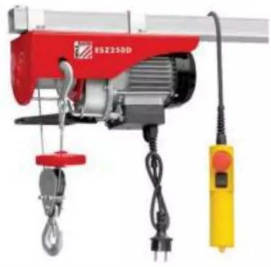
natural_image
Red and silver electric lift with attached control panel and power plug (no visible text or symbols)ESZ 500D
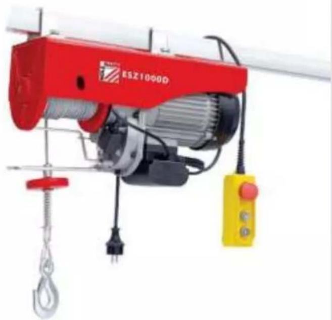
natural_image
Red ESZ 1000D electric lift with hanging hook and control buttons (no visible text or symbols)1 INHALT /INDEX
14.1 Operation instructions.... 18
14.2 Operation....19
14.2.1 Use with deflection pulley....19
15 MAINTENANCE 20
15.1 Maintenance plan....20
15.2 Cleaning 20
15.3 Disposal 20
16 SCHALTPLAN / WIRING DIAGRAM 21
17 ERSATZTEILE / SPARE PARTS 22
natural_image
Technical line drawing of a mechanical device with a magnified inset showing internal components (no text or symbols)8 BETRIEB
natural_image
Three abstract hatched patterns with no text or symbols, arranged horizontally (no readable text or symbols)natural_image
Technical line drawing of a mechanical device with cable and hook components, shown in two views: top is circular (no text or symbols)natural_image
Technical line drawings of mechanical lifting components (no text or symbols)This manual contains information and important instructions for the installation and correct use of the electric rotary hoist frames ESZ 250D / ESZ 500D / ESZ 1000D.
Following the usual commercial name of the device (see cover) is substituted in this manual with the name "machine".
This manual is part of the product and shall not be stored separately from the product. Save it for later reference and if you let other people use the product, add this instruction manual to the product.

Please read and obey the security instructions!
Before first use read this manual carefully. It eases the correct use of the product and prevents misunderstanding and damages of product and the user's health.
Due to constant advancements in product design, construction pictures and content may diverse slightly. However, if you discover any errors, inform us please.
Technical specifications are subject to changes!
Please check the product contents immediately after receipt for any eventual transport damage or missing parts.
Claims from transport damage or missing parts must be placed immediately after initial product receipt and unpacking before putting the product into operation.
Please understand that later claims cannot be accepted anymore.
Copyright
© 2016
This document is protected by international copyright law. Any unauthorized duplication, translation or use of pictures, illustrations or text of this manual will be pursued by law. Court of jurisdiction is the Landesgericht Linz or the competent court for 4170 Haslach, Austria!
Customer service contact
| Lifting hook | Deflection pulley |
| Mounting screws (4x) | Mounting bracket (2x) |
11.3 Technical details
| ESZ 250D | ESZ 500D | ESZ 1000D | |
| Voltage | 230 V / 50Hz | 230 V / 50Hz | 230 V / 50Hz |
| Motor power | 500 W | 900 W | 1600 W |
| max. payload with/without deflection pulley | 250 / 125 kg | 500 / 250 kg | 999 / 500 kg |
| max. lifting height with/without deflection pulley | 6 / 12 m | 6 / 12 m | 6 / 12 m |
| Lifting speed with/without deflection pulley | 4 / 8 m/min | 4 / 8 m/min | 4 / 8 m/min |
| Steel rope diameter ∅ | 3 mm | 4,2 mm | 5,6 mm |
| Rope tensile strength | ≥1870 N/mm ^2 | ≥1770 N/mm ^2 | ≥1770 N/mm ^2 |
| Protection mode | IP 54 | IP 54 | IP 54 |
| Weight | 10,5 kg | 16,5 kg | 33 kg |
12 SAFETY
12.1 Intended Use
The machine must only be used for its intended purpose! Any other use is deemed to be a case of misuse.
To use the machine properly you must also observe and follow all safety regulations, the assembly instructions, operating and maintenance instructions lay down in this manual.
All people who use and service the machine have to be acquainted with this manual and must be informed about the machine's potential hazards.
It is also imperative to observe the accident prevention regulations in force in your area.
The same applies for the general rules of occupational health and safety.
The machine is used for:
Lifting fixed loads.
Any manipulation of the machine or its parts is a misuse, in this case HOLZMANN-MASCHINEN and its sales partners cannot be made liable for ANY direct or indirect damage.

WARNING
- The motor of the machine is protected with a thermal fuse. When the thermal fuse responses, the machine stops. The machine can be used again only after cooled down (app. 5 minutes).
- The machine is suitable for operating mode S3 (25% operating time: 2,5 min at 10 min) and not for continuous operation.
Ambient conditions:
The machine may be operated:
humidity
max. 70%
temperature
+5°C to +40°C
The machine shall not be operated in areas exposed to increased fire or explosion hazard.
Prohibited use:
- The operation of the machine outside the stated technical limits described in this manual is forbidden.
- The operation of the machine without provided protective devices is prohibited
- The use of the machine not according with the required dimensions is forbidden.
- Any manipulation of the machine and parts is forbidden.
- The use of the machine for any purposes other than described in this user-manual is forbidden.
- The unattended operation on the machine during the working process is forbidden!
- It is explicitly prohibited that persons stayed or walked under or in the immediate vicinity of the suspended load!
• To lift loads connected to earth is forbidden! - Swinging with the hung load is forbidden!
- Lifting of loads hung outside of axis of gravity is forbidden!
• To lift people or animals is explicitly forbidden!
12.2 Security instructions
Missing or non-readable security stickers have to be replaced immediately!
The locally applicable laws and regulations may specify the minimum age of the operator and limit the use of this machine!
To avoid malfunction, machine defects and injuries, read the following security instructions!

NOTICE
In this machine following protective equipment is in effect:
• Emergency-switch on controller
- Limit switch up and down

- Keep your work area dry and tidy! An untidy work area may cause accidents. Avoid slippery floor.
• Make sure the work area is lighted sufficiently
• Always stay focused when working. Reduce distortion sources in your working environment. The operation of the machine when being tired, as well as under the influence of alcohol, drugs or concentration influencing medicaments is forbidden.
- Only one person shall operate the machine.
- The machine must be operated only by trained persons (knowledge and understanding of this manual), which have no limitations of motor skills compared with conventional workers.

• Make sure there is nobody present in the dangerous area. The minimum safety distance is 10 m
• Use personal safety equipment: safety shoes S1, work wear when working with or on the machine!

- Never leave the machine running unattended! Before leaving the working area switch the machine off and wait until the machine stops.
• Always disconnect the machine prior to any actions performed at the machine!
- Do not use the machine with damaged switch

- The plug of an electrical tool must strictly correspond to the socket. Do not use any adapters together with earthed electric tools
• Each time you work with an electrically operated machine, caution is advised! There is a risk of electric shock, fire
- Protect the machine from dampness (causing a short circuit)
- Check the cable regularly for damage
- Do not use the cable to carry the machine or to fix the load
- Protect the cable from heat, oil and sharp edges
- Avoid body contact with earthed components
- Keep any machine that is not being used out of reach of children




NOTICE
Emergency procedure
A first aid kit should always be readily available for a possible accident. Initiate the violation in accordance with the necessary first aid measures. When requesting support, provide the following details::
-
Place of accident
-
Type of accident
-
Number of injured people
-
Injury type(s)
13 ASSEMBLY
Please check the product contents immediately after receipt for any eventual transport damage or missing parts. Claims from transport damage or missing parts must be placed immediately after initial machine receipt and unpacking before putting the machine into operation. Please understand that later claims cannot be accepted anymore.

ATTENTION
- Ensure conscientious assembly of the machine.
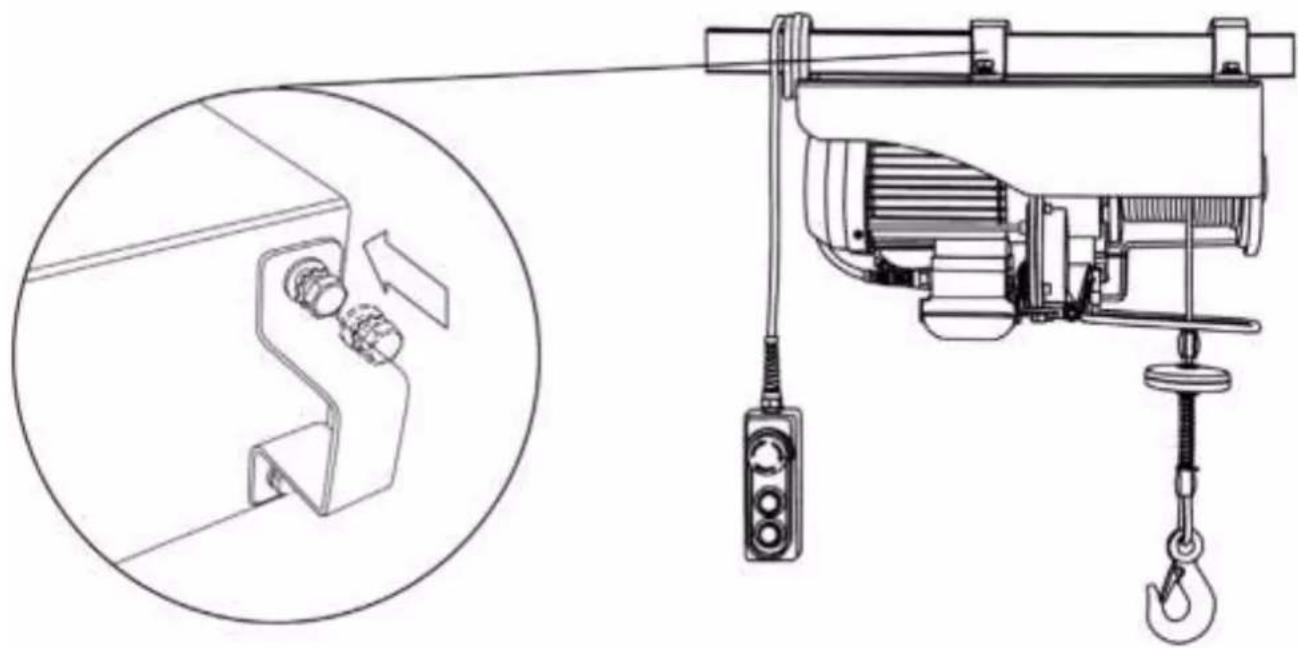
- The structural part the machine is to be fixed to must be able to bear at least the double value of the expected payload
• Make sure the appliance is always fixed horizontally and never awry. - Tighten firmly all bolts, using washers and snap rings.
- At regular intervals, please check the fastening clamps for any damage, cracks, etc.
- Ensure that the support, where the machine will be mounted is securely mounted.
- Never exceed the maximum payload!
natural_image
Technical line drawing of a mechanical device with a magnified inset showing a close-up of a component (no text or symbols present)14 OPERATION
Machine to be operated in a perfect state only. Inspect the device visually every time it is to be used. Check in particular the safety equipment, electrical controls, electric cables and screwed connection for damage and if tightened properly. Replace any damaged parts before operating the device.
14.1 Operation instructions

WARNING
Perform all machine settings with the machine being disconnected from the power supply!

NOTICE
• Inspect the machine visually before each use.
- The steel rope needs to be checked for any damage each time you put it into operation. It is strictly prohibited to use the machine when the steel rope is damaged!

natural_image
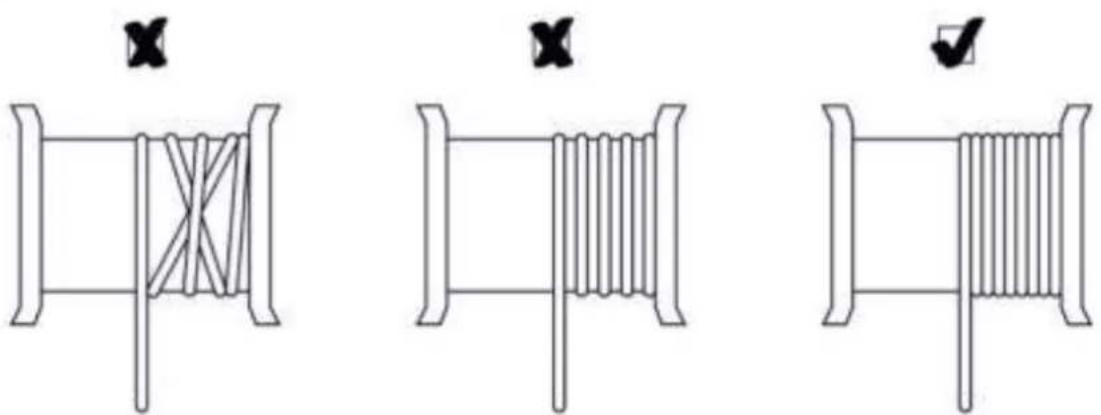
Three abstract hatched patterns with diagonal hatching, no text or symbols present• Make sure the steel rope always reels up smoothly on the rope drum.
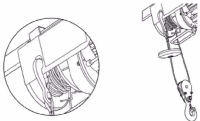
- In particular, check the perfect state of the snap hooks preventing any unintentional release of the lifting hook from slings (ropes, rings, transportation eyes, etc.).
- All lifting work is only allowed when appropriate fixing elements (ropes, rings, transport loops, etc.) are used and when in accordance with appropriate provisions and standards valid in the workplace.
- The machine can only be used for lifting of loads whose weight does not exceed the maximum payload specified by the producer in technical data and on the type label of the machine.
- Attach the load correctly.
- Lifted loads may only be lifted in a vertical position! Never pull and lift in an inclined position!!
• The steel rope must not be used for load fixing. - When using the deflection pulley, hang the lifting hook into the hook holder of the carrier housing.
14.2 Operation
- Check, whether the emergency switch (11) is pressed. For unlocking, turn the emergency switch (1) clockwise.
- For lifting the load, press the up-down-switch ▲ (10).
- For lowering the load, press the up-down-switch ▼ (10).
- The machine is provided with up limit switch and down limit switch, which prevent that the steel rope is completely or wrongly unwound and/or the load is lifted up too high.
Never totally unwind the rope. At least 2 windings of the rope must remain on the drum!
• In the emergency case press the emergency switch (11) immediately. The machine stops.
14.2.1 Use with deflection pulley
natural_image
Technical line drawing of a mechanical device with cable and hook components, shown in two views: top is circular (no text or symbols)- The machine is provided with a deflection pulley and hook. When they are used correctly the machine can lift double payload.
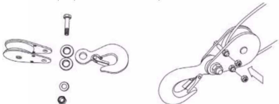
- Mount the deflection pulley as shown on the below picture.
natural_image
Technical line drawings of mechanical lifting components (no text or symbols)- When using the deflection pulley, hang the lifting hook into the hook holder of the carrier housing. With help of 2 steel ropes to lift the load the machine is now capable to lift the double load.
15 MAINTENANCE

ATTENTION
Perform all maintenance machine settings with the machine being disconnected from the power supply!
Serious injury due to unintentional or automatic activation of the machine!

The machine does not require extensive maintenance. If malfunctions and defects occur, let it be serviced by trained persons only.
NOTICE
Clean your machine regularly after every usage – it prolongs the machines lifespan and is a prerequisite for a safe working environment.
Repair jobs shall be performed by respectively trained professionals only.
Check regularly the condition of the security stickers. Replace them if required.
Check regularly the condition of the machine!
Store the machine in a closed, dry location.
15.1 Maintenance plan
- Check regularly the correct function of the limit switches and the emergency switch.
- Per 30 cycles check the condition of the steel rope. If there are any damages replace the steel rope in accordance with the technical details.
• Per 200 cycles lubricate the steel rope and the deflection pulley.
• Per 1000 cycles check that the screws of the mounting brackets are well tightened
• Per 1000 cycles check that the hook and the deflection pulley are in good conditions. - Per 1000 cycles inspect the braking system. If there are abnormal noises in the motor or the machine is unable to hold the payload the braking system must be checked.
Per cycle means that the operator operates the load up and down for one time.
15.2 Cleaning

HINWEIS
The usage of certain solutions containing ingredients damaging metal surfaces as well as the use of scrubbing agents will damage the machine surface!
Never spray water on the machine or submerge it to any liquid.
15.3 Disposal
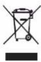
Do not dispose the machine in residual waste. Contact your local authorities for information regarding the available disposal options. When you buy at your local dealer for a replacement unit, the latter is obliged to exchange your old.
16 SCHALTPLAN / WIRING DIAGRAM
ESZ 250D, ESZ 500D:
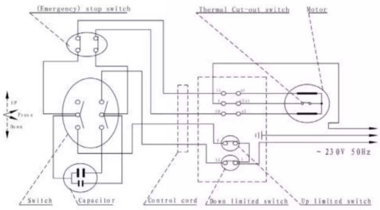
flowchart
graph TD
    A["(Emergency) stop switch"] --> B["Switch"]
    A --> C["Capacitor"]
    D["Thermal Cut-out switch"] --> E["Motor"]
    F["Control cord"] --> G["Down limited switch"]
    G --> H["Up limited switch"]
    I["UP Press Down"] --> A
    J["-230V 50Hz"] --> G
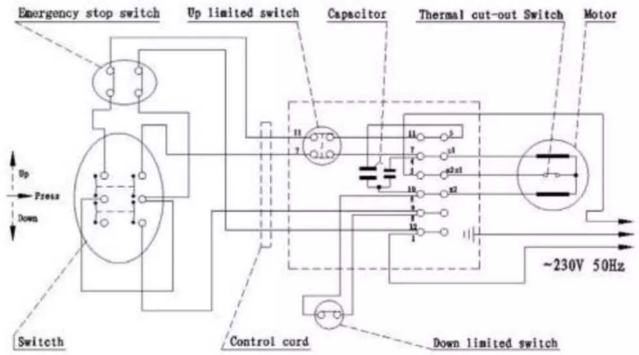
ESZ 1000D:
17 ERSATZTEILE / SPARE PARTS
With original HOLZMANN spare parts you use parts that are attuned to each other shorten the installation time and elongate your products lifespan.
IMPORTANT
The installation of other than original spare parts voids the warranty!
So you always have to use original spare parts
When you place a spare parts order please use the service formular you can find in the last chapter of this manual. Always take a note of the machine type, spare parts number and partname. We recommend to copy the spare parts diagram and mark the spare part you need.
You find the order address in the preface of this operation manual.
| No. | Part name | Qty. | No. | Part name | Qty. |
| 1 | Bracket | 1 | 32 | Chassis | 1 |
| 2 | Fixing ring | 2 | 33 | Brake spring | 1 |
| 3 | Hexagon bolt | 4 | 34 | Brake assembling | 1 |
| 4 | Socket cap screw | 2 | 35 | Bearing | 1 |
| 5 | Cradle | 1 | 36 | Motor cover | 1 |
| 6 | Embed pin | 2 | 37 | Extra long hexagon bolt | 4 |
| 7 | Rope drum | 1 | 39 | Fan cover | 1 |
| 8 | Drum washer | 2 | 39 | Fan blade | 1 |
| 9 | Limit block | 1 | 40 | Lim t switch contactor | 2 |
| 10 | Steel cable | 1 | 41 | Lim t shaft seal | 2 |
| 11 | Fastening sleeve of rope | 2 | 42 | Up limit switch | 1 |
| 12 | Shrink-Ring of rope | 1 | 43 | Down limit switch | 1 |
| 13 | Hook | 1 | 44 | Connection box | 1 |
| 14 | Limit lever Assy. | 1 | 45 | Base of connection box | 1 |
| 15 | Down limit pole | 1 | 46 | Terminal Block | 1 |
| 16 | Inner hexagon screw | 1 | 47 | Four-core cable | 1 |
| 17 | Rope drum shaft | 1 | 48 | Plug | 1 |
| 18 | Flat pin | 1 | 49 | Cord clip (Small) | 1 |
| 19 | Bearing | 1 | 50 | Cord clip (Big) | 2 |
| 20 | Gear box | 1 | 51 | Ioc shaft | 2 |
| 21 | Cap screw | 8 | 52 | Anti-slip screw | 2 |
| 22 | Seone stage gear | 1 | 53 | Pulley assembling | 1 |
| 23 | Paper sea | 1 | 54 | Hoc for pulley | 1 |
| 24 | Bearing | 1 | 55 | Positive and negative switch | 1 |
| 25 | Middle shaft | 1 | 56 | Emergency stop switch | 1 |
| 26 | First stage gear | 1 | 57 | Handle | 1 |
| 27 | Bearing | 1 | 58 | Capacitor | 1 |
| 28 | Front cover | 1 | 59 | Cross recessed pan head screws | 1 |
| 29 | Bearing | 1 | 60 | Hard steel cable Assy. | 1 |
| 30 | Rotor | 1 | 61 | Cross recessed pan head tapping screws | 1 |
| 31 | Stator | 1 |
17.2.2 ESZ 1000D
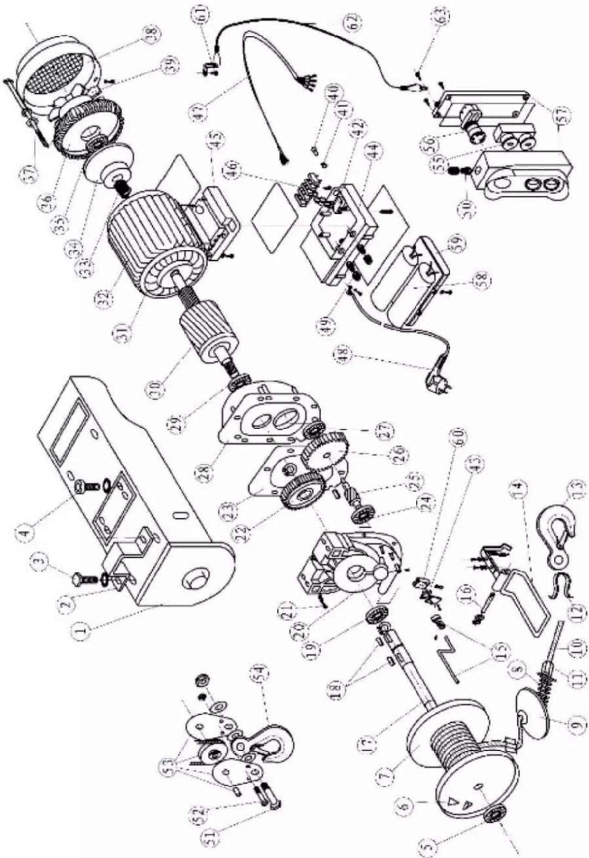
| No. | Description | Qua. | No. | Description | Qua. |
| 1 | Bracket | 1 | 33 | Brake Spring | 1 |
| 2 | Fixing Ring | 2 | 34 | Brake Assembly | 1 |
| 3 | Hexagon Bolt | 4 | 35 | Bearing | 1 |
| 4 | Socket cap Screws | 2 | 36 | Motor Cover | 1 |
| 5 | Bearing | 1 | 37 | Extra long Hexagon Bolt | 4 |
| 6 | Embed Pin | 2 | 38 | Fan Cover | 1 |
| 7 | Rope Drum | 1 | 39 | Fan Blade | 1 |
| 8 | Spring Buffer Assy. | 1 | 40 | Limit Switch Contactor | 2 |
| 9 | Limit Block | 1 | 41 | Limit Shaft Seal | 2 |
| 10 | Steel Cable | 1 | 42 | Up Limit Switch | 1 |
| 11 | Fastening Sleeve of Rope | 2 | 43 | Down Limit Switch | 1 |
| 12 | Shrink-Ring of Rope | 1 | 44 | Connection Box | 1 |
| 13 | Hook | 1 | 45 | Base of Connection Box | 1 |
| 14 | Limit Lever Assy. | 1 | 46 | Terminal Block | 1 |
| 15 | Down Limit Pole | 1 | 47 | Four Core Cable | 1 |
| 16 | Socket Cap Screws | 1 | 48 | Plug | 1 |
| 17 | Rope Drum Shaft | 1 | 49 | Cord Clip (Small) | 1 |
| 18 | Flat Pin | 1 | 50 | Cord Clip (Big) | 2 |
| 19 | Bearing | 1 | 51 | Hook Shaft | 2 |
| 20 | Gear Box | 1 | 52 | Anti-Slip Screw | 2 |
| 21 | Cap Screws | 8 | 53 | Pulley Assembly | 1 |
| 22 | Second Stage Gear | 1 | 54 | Hook for Pulley | 1 |
| 23 | Paper Seal | 1 | 55 | Positive and Negative Switch | 1 |
| 24 | Bearing | 1 | 56 | Emergency Stop Switch | 1 |
| 25 | Middle Shaft | 1 | 57 | Handle | 1 |
| 26 | First Stage Gear | 1 | 58 | Capacitor | 1 |
| 27 | Bearing | 1 | 59 | Connecting Housing Cover | 1 |
| 28 | Front Cover | 1 | 60 | Down Limit Box | 1 |
| 29 | Bearing | 1 | 61 | Cross Recessed Pan Head Screws | 1 |
| 30 | Rotor | 1 | 62 | Hand Steel Cable Assy. | 1 |
| 31 | Stator | 1 | 63 | Cross Recessed Pan Head Tapping Screws | 1 |
| 32 | Chassis | 1 |
18 EU-KONFKORMITÄTSERKLÄRUNG / CE-CERTIFICATE OF CONFORMITY
CE
Inverkehrbringer / Distributor
Hereby we declare that the above mentioned machines meet the essential safety and health requirements of the above stated EC directives. Any manipulation or change of the machine not being explicitly authorized by us in advance renders this document null and void.
Please consult our troubleshooting section for initial problem solving. Feel free to contact your HOLZMANN reseller or us for Customer Support!
Warranty claims based on your sales contract with your HOLZMANN retailer, including your statutory rights, shall not be affected by this guarantee declaration. HOLZMANN-MASCHINEN grants guarantee according to following conditions:
A) The guarantee covers the correction of deficiencies to the tool/product, at no charge, if it can be verified adequately that the deficiencies were caused by a material or manufacturing fault.
B) The guarantee period lasts 12 months, and is reduced to 6 months for tools in commercial use. The guarantee period begins from the time the new tool is purchased from the first end user. The starting date is the date on the original delivery receipt, or the sales receipt in the case of pickup by the customer.
C) Please lodge your guarantee claims to your HOLZMANN reseller you acquired the claimed tool from with following information:
Original Sales receipt and/or delivery receipt
Service form (see next page) filed, with a sufficient deficiency report
for spare part claims: a copy of the respective exploded drawing with the required spare parts being marked clear and unmistakable.
D) The Guarantee handling procedure and place of fulfillment is determined according to HOLZMANNs sole discretion in accordance with the HOLZMANN retail partner. If there is no additional Service contract made including on-site service, the place of fulfillment is principally the HOLZMANN Service Center in Haslach, Austria.
Transport charges for sending to and from our Service Center are not covered in this guarantee.
E) The Guarantee does not cover:
- Wear and tear parts like belts, provided tools etc., except to initial damage which has to be claimed immediately after receipt and initial check of the product.
- Defects in the tool caused by non-compliance with the operating instructions, improper assembly, insufficient power supply, improper use, abnormal environmental conditions, inappropriate operating conditions, overload or insufficient servicing or maintenance.
• Damages being the causal effect of performed manipulations, changes, additions made to the product.
• Defects caused by using accessories, components or spare parts other than original HOLZMANN spare parts.
- Slight deviations from the specified quality or slight appearance changes that do not affect functionality or value of the tool.
- Defects resulting from a commercial use of tools that - based on their construction and power output - are not designed and built to be used within the frame of industrial/commercial continuous load.
F) Claims other than the right to correction of faults in the tool named in these guarantee conditions are not covered by our guarantee.
G) This guarantee is voluntary. Therefore Services provided under guarantee do not lengthen or renew the guarantee period for the tool or the replaced part.
SERVICE
After Guarantee and warranty expiration specialist repair shops can perform maintenance and repair jobs. But we are still at your service as well with spare parts and/or product service. Place your spare part / repair service cost inquiry by filing the SERVICE form on the following page and send it:
via Mail to info@holzmann-maschinen.at
or via Fax to: +43 7289 71562 4
21 PRODUKTBEOBACHTUNG PRODUCT EXPERIENCE FORM
We observe the quality of our delivered products in the frame of a Quality Management policy.
Your opinion is essential for further product development and product choice. Please let us know about your:
- Impressions and suggestions for improvement.
- experiences that may be useful for other users and for product design
- Experiences with malfunctions that occur in specific operation modes
We would like to ask you to note down your experiences and observations and send them to us via FAX, E-Mail or by post:
Erworben von / purchased from:
E-Mail/ e-mail:
service inquiry spare part inquiry guarantee claim
Please describe amongst others in the problem: What has cause the problem/defect, what was the last activity before you noticed the problem/defect! For electrical problems Have you had checked you electric supply and the machine already by a certified electrician?
3. Bitte beachten
Additional information
INCOMPLETELY FILLED SERVICE FORMS CANNOT BE PROCESSED! FOR GUARANTEE CLAIMS PLEASE ADD A COPY OF YOUR ORIGINAL SALES / DELIVERY RECEIPT OTHERWISE IT CANNOT BE ACCEPTED FOR SPARE PART ORDERS PLEASE ADD TO THIS SERVICE FORM A COPY OF THE RESPECTIVE EXPLODED DRAWING WITH THE REQUIRED SPARE PARTS BEING MARKED CLEARLY AND UNMISTAKABLE. THIS HELPS US TO IDENTIFY THE REQUIRED SPARE PARTS FASTLY AND ACCEL- ERATES THE HANDLING OF YOUR INQUIRE.
- INHALT /INDEX
- MAINTENANCE 20
- SCHALTPLAN / WIRING DIAGRAM 21
- ERSATZTEILE / SPARE PARTS 22
- BETRIEB
- Please read and obey the security instructions!
- Copyright
- Customer service contact
- Technical details
- SAFETY
- Intended Use
- WARNING
- Ambient conditions:
- Prohibited use:
- Security instructions
- NOTICE
- Emergency procedure
- ASSEMBLY
- ATTENTION
- OPERATION
- Operation instructions
- Operation
- Use with deflection pulley
- MAINTENANCE
- Maintenance plan
- Cleaning
- HINWEIS
- Disposal
- SCHALTPLAN / WIRING DIAGRAM
- ERSATZTEILE / SPARE PARTS
- IMPORTANT
- The installation of other than original spare parts voids the warranty!
- ESZ 1000D
- EU-KONFKORMITÄTSERKLÄRUNG / CE-CERTIFICATE OF CONFORMITY
- SERVICE
- PRODUKTBEOBACHTUNG PRODUCT EXPERIENCE FORM
- Bitte beachten
- Additional information
Brand : Holzmann
Model : ESZ 1000D
Category : Uncategorized