
IQ-MC8 - Manuel d'utilisation d'équipement audio CROWN - Free user manual and instructions
Find the device manual for free IQ-MC8 CROWN in PDF.


| Product Type | IQ Bus Interface Module for Amplifier Control and Monitoring |
| Brand | Crown Audio |
| Model | IQ-MC8 |
| Compatibility | CTs 4200 and CTs 8200 amplifiers; IQ System with IQ2-compatible interface |
| IQ Bus Communication | Optically isolated 20 mA serial loop; 38.4 K BAUD; half duplex; RJ-45 connectors |
| Audio Performance | Max input level +20 dBu; dynamic range >100 dB; frequency response ±0.5 dB 20 Hz-20 kHz; THD+N <0.05%; CMR >50 dB |
| Signal Processing | Input compressor/limiter, peak voltage limiter, average power limiter |
| Load Supervision | Real-time monitoring of load impedance with high/low limit alerts |
| Controls | 8-segment DIP switch for IQ address (1-250); recessed reset/preset switch |
| Indicators | Amber DATA LED (IQ command received); green PRESET LED (current preset number) |
| Connectors | IQ Bus: RJ-45 input and daisy output; AUX In/Out and Listen Bus: RJ-11 |
| Memory Backup | 8 Kbyte EEPROM; 80,000 write cycles minimum; retains settings after power loss |
| Power Supply | Powered by host amplifier (no external power required) |
| Certifications | FCC Part 15 Class B; EN 55103-1/2; EN 60065 safety standard |
| Warranty | 3 years (USA & Canada); full warranty covers defects and failures regardless of reason |
| Service | Factory service available; contact Crown Technical Support or local distributor |
Frequently Asked Questions - IQ-MC8 CROWN
User questions about IQ-MC8 CROWN
0 question about this device. Answer the ones you know or ask your own.
Ask a new question about this device
Download the instructions for your Manuel d'utilisation d'équipement audio in PDF format for free! Find your manual IQ-MC8 - CROWN and take your electronic device back in hand. On this page are published all the documents necessary for the use of your device. IQ-MC8 by CROWN.
USER MANUAL IQ-MC8 CROWN
natural_image
Black and white circular logo with a crown symbol (no text or numbers)CROWN

Modules
REFERENCE MANUAL
IQ-MC8 & IQ-MC4
© 2004 by Crown Audio, Inc., P.O. Box 1000, Elkhart, IN 46515-1000 U.S.A. Telephone: 574-294-8000. Fax: 574-294-8329. Trademark Notice: IQ2, SmartAmp and PIP are trademarks. Crown and IQ System are registered trademarks of Crown International. Other trademarks are the property of their respective owners.
Obtaining Other Language Versions:
To obtain information in another language about the use of this product, please contact your local Crown Distributor. If you need assistance locating your local distributor, please contact Crown at 574-294-8200.
Note: The information provided in this manual was deemed accurate as of the publication date. However, updates to this information may have occurred. To obtain the latest version of this manual, please visit the Crown website at www.crownaudio.com.

Printed onPrinted on recycled paper.recycled paper.
134505-3 3/04
The information furnished in this manual does not include all of the details of design, production, or variations of the equipment. Nor does it cover every possible situation which may arise during installation, operation or maintenance. If you need special assistance beyond the scope of this manual, please contact Crown Technical Support.
Crown Technical Support
1718 W. Mishawaka Rd., Elkhart, Indiana 46517 U.S.A.
Phone: 800-342-6939 (North America, Puerto Rico and Virgin Islands) or 574-294-8200
Fax:574-294-8301 Internet:http://www.crownaudio.com

WARNING
TO REDUCE THE RISK OF ELECTRIC SHOCK, DO NOT EXPOSE THIS EQUIPMENT TO RAIN OR MOISTURE!
FCC COMPLIANCE NOTICE
This device complies with part 15 of the FCC rules. Operation is subject to the following two conditions: (1) This device may not cause harmful interference, and (2) this device must accept any interference received, including interference that may cause undesired operation.
CAUTION: Changes or modifications not expressly approved by the party responsible for complicance could void the user's authority to operate the equipment.
NOTE: This equipment has been tested and found to comply with the limits for a Class B digital device, pursuant to part 15 of the FCC Rules. These limits are designed to provide reasonable protection against harmful interference in a residential installation. This equipment generates, uses, and can radiate radio frequency energy and, if not installed and used in accordance with the instruction manual, may cause harmful interference to radio communications. However, there is no guarantee that interference will not occur in a particular installation. If this equipment does cause harmful interference to radio or television reception, which can be determined by turning the equipment off and on, the user is encouraged to try to correct the interference by one or more of the following measures:
- Reorient or relocate the receiving antenna.
- Increase the separation between the equipment and receiver.
- Connect the equipment into an outlet on a circuit different from that to which the receiver is connected.
- Consult the dealer or an experienced radio/TV technician for help.
DECLARATION OF CONFORMITY
Crown Audio, Inc.
1718 W. Mishawaka Rd.
Elkhart, IN 46517 U.S.A.
Susan Whitfield
574-294-8289
swhitfield@crownintl.com
European Representative's Name and Address:
Nick Owen
19 Clos Nant Coslech
Pontprennau
Cardiff
CF23 8ND United Kingdom
Equipment Type: Control System Components
Family Name: IQ Series
Model Name: IQ-MC4, IQ-MC8
EMC Standards:
EN 55103-1:1995 Electromagnetic Compatibility – Product Family Standard for Audio, Video, Audio-Visual and Entertainment Lighting Control Apparatus for Professional Use, Part 1: Emissions
EN 55103-1:1995 Magnetic Field Emissions-Annex A @ 10 cm and 1 M
EN 61000-3-3:1995 Limitation of Voltage Fluctuations and Flicker in Low-Voltage Supply Systems Rated Current ≤16A
EN 55022:1992 + A1:1995 & A2:1997 Limits and Methods of Measurement of Radio Disturbance Characteristics of ITE: Radiated, Class B Limits; Conducted, Class B
EN 55103-2:1996 Electromagnetic Compatibility – Product Family Standard for Audio, Video, Audio-Visual and Entertainment Lighting Control Apparatus for Professional Use, Part 2: Immunity
EN 61000-4-2:1995 Electrostatic Discharge Immunity (Environment E2-Criteria B, 4k V Contact, 8k V Air Discharge)
EN 61000-4-3:1996 Radiated, Radio-Frequency, Electromagnetic Immunity (Environment E2, criteria A)
EN 61000-4-4:1995 Electrical Fast Transient/Burst Immunity (Criteria B)
EN 61000-4-5:1995 Surge Immunity (Criteria B)
EN 61000-4-6:1996 Immunity to Conducted Disturbances Induced by Radio-Frequency Fields (Criteria A)
EN 61000-4-11:1994 Voltage Dips, Short Interruptions and Voltage Variation
Safety Standard:
EN 60065: 1998 Safety Requirements – Audio Video and Similar Electronic Apparatus
I certify that the product identified above conforms to the requirements of the EMI Council Directive 89/335/EEC as amended by 92/31/EEC, and the Low Voltage Directive 73/23/EES as amended by 93/68/EEC.
Signed
Date of issue: March 24, 2004

Larry Coburn
Title: Senior Vice President of Manufacturing
Content
1 Welcome .... 5
2 Controls, Connectors & Indicators 6
3 Installation 7
3.1 Prepare the MC-IQ Module 7
3.2 Install the Wiring 8
3.3 Adjust System Levels 10
4 Operation ......11
4.1 Hardware 11
4.1.1 Data Signal Presence Indicator .... 11
4.1.2 Preset Indicator 11
4.1.3 IQ Bus Input Connector 11
4.1.4 IQ Bus Daisy
Output Connector .... 11
4.1.5 Aux Input/Output and Listen Bus Connector 11
4.1.6 IQ Bus "Drop Out" Relays 12
4.2 Hardware Controls 12
4.2.1 IQ Address Switch (S1) 12
4.2.2 Reset/Preset Switch 12
4.3 Amplifier Control and Monitoring ..... 13
4.3.1 User Presets 13
4.3.2 Clip Monitor 13
4.3.3 Input Signal Level Monitor ..... 13
4.3.4 Output Signal Level Monitor ..... 13
4.3.5 Thermal Headroom
Level Monitor .... 13
4.3.6 Ready/Standby Control 14
4.3.7 Signal Mute 14
4.3.8 Polarity Inverter 14
4.3.9 Input Signal Attenuator 14
4.3.10 "Ghost Faders" 14
4.3.11 Amp Information 14
4.3.12 Amp Mode 14
4.3.13 Error Reporting 14
4.4 Signal Processing 15
4.4.1 Input Signal
Compressor/Limiter 15
4.4.2 Peak Voltage Limiter 15
4.4.3 Average Power Limiter 15
4.5 Load Supervision 16
5 IQ Audio In Depth 17
5.1 A Closer Look at IQ Bus Wiring 17
5.2 Using the AUX Connector.... 18
5.2.1 AUX Output 19
5.2.2 AUX Input 20
5.3 Listen Bus 20
5.4 Working with RJ-11 and RJ-45
Connectors 20
5.5 Load Supervision 21
5.5.1 Typical Load Characteristics to Know and Understand 22
6 Specifications 23
7 IQ Address Tables .....24
8 Service 28
Warranty 29

Figure 1.1 IQ-MC8 Front Panel
1 Welcome
The IQ-MC4 and IQ-MC8 modules connect CTs 4200 and CTs 8200 amplifiers to the IQ Bus of an IQ System ^® , allowing the amplifier to be controlled and monitored via IQ.
The IQ-MC module is an IQ2^TM series component. This means it supports Crown's IQ2 protocol and requires an IQ System with an IQ2-compatible IQ interface. IQ2 (universal code) enables users and third parties to develop custom software objects to control and monitor IQ2 compatible components like the IQ-MC module. Each IQ-MC module includes an IQ address switch allowing the unit to have a unique address on the IQ Bus. It is powered by the amplifier and includes a memory backup feature that enables the amplifier to resume operation with all of its settings intact after a power outage.
We strongly recommend you read all the instructions, warnings and cautions contained within. Also, for your protection, please send in the warranty registration card today and save the bill of sale since it is your official proof of purchase.
2 Controls, Connectors & Indicators

Figure 2.1 IQ-MC8 Controls, Connectors and Indicators
3 Installation
3.1 Prepare the IQ-MC Module

First, turn off and unplug the amplifier. Set the IQ address switch S1. By giving each IQ component a unique address, it can be individually controlled and monitored. Whenever the IQ System wants to send a command to just one IQ component, it first sends its address and then the command down the IQ Bus.
S1 has eight segments because it actually contains eight tiny switches inside. The word "ON" is printed on the switch along its lower left side to indicate the ON position and the switches are numbered along the bottom (Figure 3.1).

bar
| SW1 | 1 | 2 | 3 | 4 | 5 | 6 | 7 | 8 | |---|---|---|---|---|---|---|---|---| | VALUE | 1 | 2 | 4 | 8 | 16 | 32 | 64 | 128 | | ON | 1 | 2 | 3 | 4 | 5 | 6 | 7 | 8 |Figure 3.1 Address Switch (S1)
Each of the eight switches in S1 has a value which doubles as the switch number increases. For example switch 1 has a value of 1; switch 2 has a value of 2; switch 3 has a value of 4; switch 4 has a value of 8 and so on. The address is determined by adding the values of all “ON” switches. In Figure 3.1, switches 1, 3, 4 and 7 are on. Simply add the values to find the address: 1+4+8+64=77 .
A convenient series of IQ address tables are included in Section 6. The tables show the switch settings for all 250 addresses.
No two IQ components of the same type which are connected to the same IQ Bus can have the same address.* Suppose, for example, an IQ System has two IQ Bus loops, 1 and 2, and this IQ-MC module is to be installed into loop 1 and given an address of 77. No other IQ-MC modules can be given the same address in loop 1. However, an IQ-MC module in loop 2 can have the same address.
Different IQ components in the same IQ Bus loop can have the same address. For example, both an IQ-USM 810 mixer/processor and an IQ-MC module can use address 77 in the same loop.
A valid IQ address is any number from 1 to 250. Do not use a number higher than 250 since they are reserved for special use. An address of "0" (zero) should only be used for "stand alone" mode. Setting the address switch to "0" disables the IQ Bus port.
3.2 Install the Wiring
Connect the IQ-MC module to the IQ system via the IQ Bus. The IQ components in a IQ Bus loop are wired sequentially. The loop begins and ends with the IQ interface. The output of one IQ component "loops" to the input of the next and so on as shown in Figure 3.2.
There are three different types of connectors used for IQ Bus wiring on IQ components. These include DIN connectors, screw terminal plugs, and RJ-45 connectors. The IQ-MC uses RJ-45 connectors that accept standard RJ-45 plugs like the one shown in Figure 3.6, allowing the use of industry-standard straight-thru type network cables. The right RJ-45 connector is used for input and the left RJ-45 connector is used for daisy output.

Figure 3.2 Standard IQ Bus Wiring "Loops" from the Output to the Input of each IQ Component (for Hub-Style IQ Bus wiring)
The following examples show how to connect the MC-IQ to other IQ components:

Figure 3.3 RJ-45 Output to Barrier Block Input
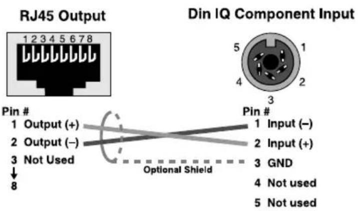
Figure 3.4 RJ-45 Output to Din Input
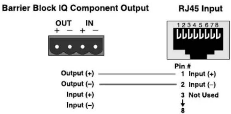
Figure 3.5 RJ-45 Input to Barrier Block Output

Figure 3.6 RJ-45 Input to Din Output
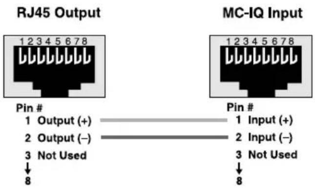
Figure 3.7 RJ-45 Output to RJ-45 Input
3.3 Adjust System Levels
Adjust attenuator levels both on the amplifier and on the IQ-MC module
control panels within your IQ software for optimum system gain.
4 Operation
With the IQ-MC option, your CTs 4200 and CTs 8200 amplifiers can be monitored and controlled from a remote location through the use of an IQ System. This module features SmartAmp™ capabilities which will enable the amplifier to function automatically. For example, the IQ-MC module can automatically limit the audio signal, also detect and report various problems.
In addition, the IQ-MC Load Supervision feature has the ability to verify the status of the loads in real time.
The IQ-MC module uses Crown's IQ2 protocol. This makes it possible for a user to design custom graphic display modules to control and monitor the unit with IQ2-compatible IQ software. This allows even greater flexibility within Crown's IQ software via custom control pages. Plus, the IQ2 protocol provides for third-party programming for system controllers such as those from AMX and Crestron.
The following sections describe the IQ-MC features and operation. Where specified, some features are accessed via controls located on the unit itself. However, many of the features can be controlled or configured using IQ for Windows software. Commands are transmitted via an IQ interface to the specified IQ component (an IQ2-compatible interface is required). Please contact your Crown representative or Crown's Technical Support Group if you are unfamiliar with IQ software.
4.1 Hardware
4.1.1 Data Signal Presence Indicator
An amber Data Signal Presence Indicator (DATA) is provided on the IQ-MC connector panel as well as the front of the amplifier. It flashes whenever commands addressed to the IQ-MC module are received. To assist with troubleshooting, an option that forces the DATA indicator to remain lit is available through IQ software.
4.1.2 Preset Indicator
A green PRESET indicator is provided on the IQ-MC connector panel. This indicator signals the number of the currently selected preset by emitting a series of flashes which match the preset number, followed by a pause. The indicator will continuously repeat the number selected until a change is made to any setting.
4.1.3 IQ Bus Input Connector
An RJ-45 connector provides the input connection to the IQ Bus. Dropout relays maintain loop integrity in the event power is removed from the IQ-MC module.
4.1.4 IQ Bus Daisy Output Connector
An RJ-45 connector is provided for normal daisy wiring output to the next device on the loop in the IQ Bus.
4.1.5 AUX Input/Output and Listen Bus Connector
An RJ-11 connector provides three functions. The AUX output delivers 15 VDC at 70 mA maximum output when switched on and may be con-
trolled via software or may be programmed to switch when a fail condition is present on any channel.* The high-impedance (10 K ohm) AUX input can sense logic signals and can be programmed to activate system mute or report fault conditions when a logic high is present. (See Section 5.2.2 for more information.) All amplifier channel's output can be monitored as a balanced line level signal which is sent to pins 1 and 6 of the RJ-11 connector (software selectable).
4.1.6 IQ Bus "Drop Out" Relays
"Drop out" relays are provided on the IQ Bus ports to maintain the continuity of the IQ communication loop even if the IQ-MC module loses power.
4.2 Hardware Controls
The following IQ-MC controls are accessed via hardware switches located on the unit.
4.2.1 IQ Address Switch (S1)
An 8-section DIP switch is used to set the IQ address of the unit. A valid IQ address is any number from 1 to 250. Numbers higher than 250 are reserved for special use.
An address of "0" places the unit in stand-alone mode. In this mode, the IQ bus port is disabled and the IQ-MC module will not function with IQ software.
This switch is located on the rear of the amplifier. Each IQ component on a IQ Bus is given a unique IQ address so it can be independently controlled and monitored. Two or more IQ components of the same type should NEVER have the same address on the same IQ Bus loop.
4.2.2 Reset/Preset Switch
A recessed reset/preset switch, accessible from outside the IQ-MC panel, performs two functions. First, it enables the IQ-MC module to be restored to factory default settings, and second, allows the user to recall any of 10 presets. A straightened paper clip or similar small object is required to press the reset switch.
-To select one of the 10 presets, complete the following steps:
Remove all input signals. With the power on, briefly press the switch for less than two seconds to toggle through the 10 user-defined presets stored in firmware. Each press will increment the selected preset by one. After the switch is released, the DATA light will flash for a moment, then the PRESET indicator will blink to indicate the preset number selected. Restore input signals.
-To restore the unit to the factory default settings, complete the following steps:
Remove all input signals. With the power on, press the switch and hold for more than 2 seconds, or until the DATA indicator blinks twice, and all settings will be reset to factory default. When the switch is released, the DATA indicator will flash rapidly for a moment. Restore input signals.
-To clear all memory and set to factory default presets:
Remove all input signals. Press in and hold the switch while applying power to the unit. The settings will be reset to factory default, with the firmware re-writing to EEPROM memory. Important: This action will re-write the memory and erase stored presets. With the button held in and power applied, the DATA and PRESET indicators will both be lit. When the button is released, the DATA and PRESET indicators will alternately blink for a few moments, indicating that memory is being written, then the DATA indicator will flash for a moment. After the unit has been reset to the factory default settings.
4.3 Amplifier Control and Monitoring
The following IQ-MC module features are accessed via IQ for Windows software.
4.3.1 User Presets
The parameters for all functions can be saved as presets. A total of 10 user presets can be stored in the IQ-MC EEPROM memory. Preset names are stored on the module.
4.3.2 Clip Monitor
The Clip indicator of each channel of the amplifier can be monitored by the IQ System. The IQ-MC module can cause a warning to flash on your computer screen via IQ for Windows software indicating a Clip event, Also, it can report Clip events to its AUX port.
4.3.3 Input Signal Level Monitor
The input signal level of each channel can be monitored. This monitor feature has a range from +20 dBu to -40 dBu in 12 -dB steps.
4.3.4 Output Signal Level Monitor
The output signal level of each channel of the amplifier can be monitored. This monitor feature has a range from 0 dB to -40 dB where 0 dB is referenced to the rated output voltage of the amplifier model.*
The IQ-MC module features scaled output level meters. By factory default, the meters are calibrated such that 0 dB equals the amplifier's rated output into 8 ohms. In 70V/100V mode, the meters default to 0 dB equals 70/100 Vrms. Auto-scaling is handled by the software.
4.3.5 Thermal Headroom Level Monitor
The Thermal Headroom level** of each channel of the amplifier can be monitored by the IQ software. This level represents the percent of available power/thermal capacity that is currently being used within the output section of the amplifier.
When the thermal headroom level reaches 100%, the amplifier cannot produce any more power and it will begin to limit the drive level to the output devices to protect them from too much stress***. The Thermal Limiter feature of the IQ-MC module can be set to engage upon a pre-selected thermal level. (See Section 4.3.14)
4.3.6 Ready/Standby Control
Each channel's output relay can be independently turned on and off.
4.3.7 Signal Mute
The output signal of each channel can be independently muted. This function typically provides 80 dB or more of attenuation.
4.3.8 Polarity Inverter
The polarity of the input signal of each channel can be independently inverted.
4.3.9 Input Signal Attenuator
An attenuator at the input of each channel is used to control the input signal level. Each attenuator has a range from 0 dB to -80 dB in 12 dB steps. (Zero equals no attenuation.)
4.3.10 "Ghost Faders"
These indicators let you monitor the signal path gain where it may differ from manual gain set on input attenuation and output trim as the result of limiting or compression. They appear as flying faders "behind" the input attenuators.
4.3.11 Amp Information
Several useful items of information about the host amplifier are determined by the IQ-MC at start-up. These include manufacturer, model, date code, serial number, and revision level. These can be printed from the system inventory (no on-screen display is available).
4.3.12 Amp Mode
The IQ-MC module screen can show:
- The position of the Dual/Bridge mode switches
- The position of the back-panel attenuators
However, the Dual/Bridge mode of the amplifier cannot be controlled via software.
4.3.13 Error Reporting
The IQ-MC module can report six types of errors: Clip, Thermal, Fault, Load, Dual/Bridge-mode switch setting has been changed, Volume attenuator setting has been changed.
You can route error reports for each condition above to:
- Windows IQ software (system software).
- AUX OUT.
- Both software and AUX OUT.
If you choose system software notification, the IQ System will notify you of the error. If you choose AUX OUT notification, the AUX OUT signal will switch from OFF to ON when a selected error has occurred. If you prefer, error reporting can be switched off. Following is a description of each error condition:
Clip: You can choose to be informed when an excessive number of Clip events occur over a unit of time in either channel of the amplifier. When Clip error reporting is on, an alert will be generated when the number of Clip events per unit of time specified exceeds a count that you set. The Count control lets you set a number of Clip events per unit of time allowed before an error is generated. The range is 1 to 100. The Time control lets you set the unit of time in seconds during which the number of Clip error events are counted for possible error reporting. The range is 1 to 10 seconds.
Thermal: You can choose to be warned if the thermal level rises above a predetermined level. The Threshold control lets you set the thermal level above which an error message will be reported. The range is from 1 to 100%.
Fault: You can choose to be warned when an amplifier "fault" condition occurs when a channel fails.
Load: You can choose to be warned if the impedance of the load being driven by the amplifier falls out of a pre-selected range. See Section 4.5 for instructions on setting up the load supervision feature.
Dual/Bridge Switch Changed: You can choose to be warned if the Dual/Bridge Switch setting has been changed. This condition risks amplifier damage or distortion. If you see this error, manually set the Dual/Bridge Switch to the correct position.
Attenuator Setting Changed: You can choose to be informed that the back-panel attenuator setting has been changed since you set it up.
4.4 Signal Processing
4.4.1 Input Signal Compressor/Limiter
An input signal compressor/limiter is available for each channel. There are five parameters which control this feature:
On/Off: Turns this function on or off.
Threshold: Sets the threshold, in dB, above which the compressor acts. The level is measured at the input to the module and corresponds to the level shown on an input meter. The compressor is "feed-forward," meaning that the level detection point is located before the gain control stage. The range is from +16 dBu to -40 dBu.
Attack Time: Sets the attack time of the compressor. The attack time is defined as the time it takes the compressor to attenuate the input signal by 10 dB. The range is from 1 millisecond to 2 seconds.
Release Time: Sets the release time of the compressor. The release time is defined as the time it takes the compressor to increase the input gain by 10 dB. The range is 100 milliseconds to 30 seconds.
Compressor Ratio: Sets the compression ratio for the compressor. The range is 1, 2, 4, 8, 16, 32, ∞ to 1.*
4.4.2 Peak Voltage Limiter
This limits the peak voltage output of the amplifier. There are four parameters which control this limiter.
On/Off: Turns the limiter on or off.
Attack: Attack time is adjustable from 10 milliseconds to 100 milliseconds per 10 dB of overdrive.
Release: Release rate is adjustable from 100 milliseconds to 10 seconds per 10 dB or release.
Threshold: Absolute voltage threshold is adjustable from 12 Vpk to 255 Vpk in 1 volt steps.
4.4.3 Average Power Limiter
Limits the long-term power output from the amp. The actual output limiter threshold is determined by an absolute power threshold and the nominal load impedance setting. There are five parameters which control this limiter.
On/Off: Turns the limiter on or off.
Average Power Threshold: The threshold is adjustable from 10 to 1000 watts.**
Nominal Load Impedance: The nominal load impedance is settable from 1 to 1000 ohms, and should be set to correspond to the nominal impedance rating of the load connected to the respective channel.
Attack Time: Adjustable from 1 second to 30 seconds in 1 second increments.
Release Time: Adjustable from 1 second to 30 seconds in 1 second increments.
4.5 Load Supervision
The Load Supervision feature allows real time monitoring of the load connected to each amplifier channel. When enabled, the IQ-MC continuously monitors the amplifier output voltage and current and calculates the long-term average load impedance. The measured load impedance is compared against user defined high and low limits. If either limit is exceeded, the status indicator and/or IQ System error reporting functions alert the user of the problem. There are six controls and two indicators for each channel:
On/Off: Turns the Load Supervision feature on or off.
High Limit: Sets the upper bound above which the system will report a "high" error status.
Low Limit: Sets the lower bound below which the system will report a "low" error status.
Nominal Load Impedance: Sets the expected average impedance for the connected load. This value determines the output signal level required for test. This parameter is also used by the average power limiter to determine the expected power limit threshold. See Section 4.4.3.
Calculate: This button invokes an impedance calculator. Entering output voltage and power will give the expected impedance.
Include in Standard Error Reporting: Enables error reporting so that any high/low status condition is reported via the IQ System (See Section 4.3.13).
Report to AUX: Enables any high/low status condition to be reported via the IQ-MC AUX port output (See Section 4.1.5).
Test Indicator: This indicator lights when the load supervision algorithm is actually performing a load impedance calculation and test verification.
Low/Normal/High Indicator: This indicator shows the present status of the load with respect to the user defined high/low limits.
Z avg Monitor: Reports actual calculated average load impedance.

flowchart
graph LR
    A["CH 1 INPUT"] --> B["Amplifier"]
    C["INPUT LEVEL METER"] --> B
    B --> D["INPUT ATTENUATOR"]
    D --> E["POLARITY INVERT AND MUTE"]
    E --> F["AMP CH 1"]
5 IQ Audio In Depth
This section provides additional information about Crown's IQ System with special guides to aid in the installation and use of the IQ-MC module. For more information about any of these topics, contact Crown Technical Support.
5.1 A Closer Look at IQ Bus Wiring
The IQ-MC module must be connected to a IQ Bus loop having an IQ2-compatible IQ interface in order for the IQ System to control or monitor it. The IQ Bus is a serial communication loop designed to transmit IQ commands and data. As implemented in the IQ-MC, it is a 20 milliamp current loop operating at a BAUD rate of 38.4 K. The loop must be unbroken to function properly.
If the system includes an IQ-INT 3 interface, it can accept eight different IQ Bus loops or zones. Dividing the sound system into different zones, each with its own IQ Bus loop, can have several advantages. The following list contrasts those advantages with those of a single loop.
Multiloop Advantages
- A break in communication in one loop does not affect other loops.
• Over 250 IQ components of the same type can be used in a system. - The same IQ address can be used more than once (once per loop per model).
Single Loop Advantages
(with IQ-INT 3 interfaces)
- The IQ System can send and retrieve data faster in a single loop.
- "Real time" level display of a greater number of units is possible.
The IQ-MC module can be connected to the IQ Bus with inexpensive twisted-pair wiring (shielded or unshielded). If fiber optic wiring is required contact Crown Technical Support (see page 28).
Here are some guidelines for twisted-pair wiring:
- Use shielded twisted-pair wire at least 26 AWG in size when interference is a problem. The wire should be of good quality and should have low capacitance—30 picofarads/foot or less is good. The shield serves two purposes: First, it helps prevent the IQ data signal from transmitting to nearby audio wiring. Second, it helps prevent outside RF from interfering with the data signal. However, in most cases interference is not a problem and, since unshielded wire has lower capacitance, it is a better choice.
- Minimize the total capacitance of each IQ Bus loop. The total capacitance should be less than 30 nanofarads. Allow for approximately 60 picofarads for each IQ component in a loop. This accounts for a slight delay which occurs as data signals pass through a component.
- Add an IQ Repeater (RPT3) for very long loops—greater than 1,000 feet (305 m)—or when required by high-capacitance wire. Although we recommend a repeater for loops longer than 1,000 feet, it is often possible to go 2,000 feet (610 m) or more. The most significant characteristic of the wire is its capacitance. Lower capacitance allows longer loops. Unshielded wire usually has less capacitance.
- Never use the ground wire in a mic snake line. It may sometimes be convenient to run IQ Bus data signals to and from stage monitor amplifiers along unused wire pairs in a mic snake. Do not use the ground wire which is normally connected to pin 1 on an XLR connector or data noise will be added to the audio lines. Use only the signal lines which normally connect to pins 2 and 3 of the XLRs.*
Outside RF interference is seldom a problem for a IQ Bus loop—especially if shielded twisted-pair wire is used. However, there are extreme situations when fiber optic wiring is recommended. For example, locating a IQ Bus loop next to an AM radio transmission line may require fiber optic cabling. An extremely long IQ Bus loop distance may also require fiber optic cabling.
5.2 Using the AUX Connector
The IQ System offers tremendous flexibility and the auxiliary feature connector provides a means of tapping into it. It can be used to turn peripherals on/off, send a signal to another system component, receive a signal from another component, and send a line level audio signal of amplifier's output.
The AUX connector is an RJ-11 type. Pins 2 and 5 are used to receive a signal and pins 3 and 4 are used to send a signal.
5.2.1 AUX Output
When the auxiliary feature is turned on by the IQ for Windows software +15 VDC is supplied across pins 3 (ground) and 4 (+). A total of 70 milliamps of current is available. The smart switch mosfet protects against shorts (see Figure 5.1).
There are many possible uses for the AUX output. For example, it can be used to turn on auxiliary cooling fans. To do this the AUX connector might be used to close a relay. The relay would then turn the fans on or off. This is shown in Figure 5.2.

Figure 5.1 The Internal AUX Circuit

Figure 5.2 A Sample AUX Output Circuit
By monitoring the operating condition of amplifiers with the IQ System software, the need for additional cooling would be apparent. The same software could then be used to turn on the appropriate AUX connector. (For more information about turning the auxiliary feature on/off, consult the IQ for Windows software documentation.)
5.2.2 AUX Input
Depending on the IQ software being used, the AUX connector can be used to sense the presence of an input signal across pins 2 (+) and 5 (ground). A +5 to +15 VDC signal at the input will be interpreted as a logic "high" and will be communicated to the IQ Bus where a host computer or controller can act upon it. A signal less than +1.6 VDC is interpreted as a logic "low."*
5.3 Listen Bus
Use the diagram in Figure 5.3 to connect an audio monitoring system, such as a headphone preamp, to the IQ-MC Listen Bus.

Figure 5.3 Listen Bus Connection
Figure 5.4 demonstrates how multiple amplifiers can be monitored using the Listen Bus. Crown's IQ for Windows software allows you to select the amplifier and channel you wish to monitor.
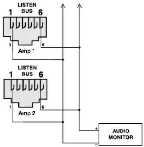
Figure 5.4 Multiple-Amp Listen Bus Configuration
5.4 Working with RJ-11 and RJ-45 Connectors
Pin assignments for standard RJ-11 and RJ-45 connectors are indicated in Figure 5.5.

Figure 5.5 RJ-11 & RJ-45 Pin Assignments
When wiring RJ-11 connectors, it is good practice to follow the USOC protocol for RJ-11 connector cable. This protocol assigns wire colors as follows:
1 white-green 4 white-blue
2 white-orange 5 orange-white
3 blue-white 6 green-white
When wiring RJ-45 connectors, it is good practice to follow the EIA/TIA 568B protocol for RJ-45 connector cable. This protocol assigns wire colors as follows:
1 white-orange 5 white-blue
2 orange-white 6 green-white
3 white-green 7 white-brown
4 blue-white 8 brown-white
Extra care must be taken when attaching RJ-11 and RJ-45 connectors to cable. Make sure you use the appropriate crimping tool and verify that the connector is properly seated into the tool, or damage will result.
Contact Crown Technical Support for additional information about working with RJ-11 and RJ-45 connectors.
5.5 Load Supervision Applications
The IQ-MC Load Supervision feature can be used to monitor the amplifier load in real time with almost any program material. Average load impedance is calculated as a function of amplifier output voltage and current. The system requires approximately 20-30 mA of average amplifier output current for adequate supervision. This allows typically low average output power levels of less than 12 watt with most loads. The maximum load impedance for reliable system performance is limited to about 50 ohms. Higher impedances can be measured but may require higher amplifier output levels for reliable operation.
Most amplifier/load systems can be configured and supervised by following these steps:
1 Configure your audio system using a known "good" load, then enable the Load Supervision feature.
2 Provide typical program material at a level high enough to light the "test" indicator.
3 Run the system at this level until the average impedance stabilizes. This may take seconds to minutes depending on level, duty-cycle, etc.
4 Set the nominal impedance at the measured value average. This optimizes the supervision algorithm for voltage and current levels versus the actual load. Note: A higher nominal setting will require higher output levels.
5 Set the high limit at twice average and the low limit at one-fourth nominal.*
6 Let the system run for extended periods using any and all typical program material.
7 Adjust the high/low limits, if necessary, to account for any variance in average measured impedance.
8 Enable error reporting, if desired.
This procedure should work well for most applications. However, some applications can be a little more difficult. Some very low-level and/or low duty-cycle signals may not adequately “test” the load. Lab and situation testing have shown output levels as small 40 dB below rated amplifier output to be enough for most low-impedance loads. Higher impedance loads such as those used in “lightly-loaded” 70V distribution lines may require signal level near 20 dB below rated output.
The “Nominal Load Impedance” control is used to optimize the system for the most accurate calculation of load impedance. It should be set to the expected nominal (or rated) impedance of the “normal” load. The high limit should be set for at least 2 times the expected nominal or actual measured load, while the low limit should be set to 12 the expected nominal or actual measured load.
The following example calculates the SPL necessary for supervision of a typical 8-ohm system. While the resulting 80-dB SPL @ 1 meter is definitely above conversation level, it is not uncomfortable.
An "8 ohm" example:
30 mA into 8 ohms = 0.007 watts
8-ohm driver sensitivity = 100dB for 1W @ 1 meter
0.007W/1W = -20dB
Required SPL for supervision test is 100dB - 20dB = 80dB SPL @ 1 meter
5.5.1 Typical Load Characteristics to Know and Understand
It is well known that the typical loudspeaker impedance is not the same for all frequencies. This variance is due to the effect of electrical properties such as the expected increase in impedance at high frequencies due to driver voice-coil inductance, or the peaks and valleys due to passive crossovers. Testing of various passive boxes has shown peaks of 100 ohms or more! Low frequency impedance variation can come from the interaction of the driver compliance with that of the box. The low frequency variations are usually wide bandwidth and may vary from 6 to 30 ohms on an 8-ohm driver.
These anomalies are easily averaged out by the IQ-MC supervision algorithm in most systems. However, there may be some extreme situations for very narrow bandwidth (i.e. single-note) signals and/or very widely varying loads that the algorithm simply cannot overcome. In these cases, widening the high and low limits will help decrease the “sensitivity” of supervision and decrease chance of “nuisance” error reports.
6 Specifications
General
Internal Controls: An 8-segment DIP switch sets the IQ address (decimal range: 1–250)*. A Reset/Preset switch, accessible with a straightened paper clip through the module's front panel, selects the next user preset if pressed for less than 2 seconds, resets settings to "factory default" if it is pressed for more than 2 seconds, or re-writes from firmware to flash memory restoring all settings to factory default if it is pressed while applying power. Jumpers select thru or processed signal for daisy output of each channel.
Connectors: IQ Bus: RJ-45 connector for input, RJ-45 connector for daisy output. AUX In/Aux Out/Listen Bus: RJ-11 connector.
Indicators: A yellow DATA indicator flashes when a valid IQ command is received from the IQ System via the IQ Bus. The DATA indicator can be forced on to facilitate rapid troubleshooting of IQ Bus wiring. A green PRESET indicator flashes to indicate the user preset number currently selected in memory. If the PRESET indicator does not flash the preset number when selected, this indicates the preset has been modified by the user.
Memory Backup: 8 Kbyte EEPROM for backup of run-time parameters, presets, and program storage. Capable of 80,000 writes minimum.
IQ Bus Data Communication
Protection: If communication is lost, the unit will continue to function with the last commands received.
Data Rate: 38.4 K BAUD.
Data Format: Serial, binary, asynchronous; 1 start bit; 1 stop bit; 8 data bits; no parity.
IQ Bus Interface Type: Optically isolated 20 milliamp serial loop.
Operation: Half duplex.
Transmission Distance: Variable from 200 to 3000 feet (61 to 914 m), depending upon wire capacitance. Typically 1000 feet (305 M) using shielded twisted-pair wire, #26 AWG or larger. Can be extended with an IQ Repeater.
Audio
Please note: The audio specifications are referenced to 0.775 V (0 dBu). Measurements were made at the output of the IQ-MC module, itself.
Maximum Input Level: +20 dBu.
Dynamic Range: >100 dB (A-weighted, 20 Hz to 20 kHz).
Frequency Response: ±0.5 dB from 20 Hz to 20 kHz.
Common Mode Rejection (CMR): 50 dB (typical).
Total Harmonic Distortion + Noise (THD+N): <0.05% (1 kHz, 0dBu).
Maximum Output Level: +20 dBu.
IQ System Data Acquisition
Multi-Channel, 14-bit Analog to Digital Converter.
Input/Output Monitor Accuracy: Typically ±1 dB.
7 IQ Address Tables
The following pages in this section contain lookup tables for every valid IQ address. The valid addresses are 1 to 250. Remember that address "0" (zero) will put the IQ-MC into a standalone mode where it is invisible to the IQ System and acts like a "dumb" balanced audio input. Do not use an address number higher than 250! Addresses above 250 are reserved for special system use.
Remember: No two IQ components of the same type which are connected to the same IQ Bus loop can have the same address.
To use the IQ address tables, simply find the address you want and set the IQ address switch of the IQ-MC module as shown.
Figure 7.1 IQ Address Switch (S1) Settings from 0 through 83
Figure 7.1 IQ Address Switch (S1) Settings from 84 through 167
Figure 7.1 IQ Address Switch (S1) Settings from 168 through 250
8 Service
To obtain factory service, fill out the service information page found in the back of this manual and send it along with your proof of purchase and the defective unit to the Crown factory.
For warranty service, we will pay for ground shipping both ways in the United States. Contact Crown Factory Service or Technical Support to obtain prepaid shipping labels prior to sending the unit. Or, if you prefer, you may prepay the cost of shipping, and Crown will reimburse you. Send copies of the shipping receipts to Crown to receive reimbursement.
Your repaired unit will be returned via UPS ground. Please contact us if other arrangements are required.
Factory Service Shipping Instructions:
-
When sending a Crown product to the factory for service, be sure to fill out the service information form that follows and enclose it inside your unit's shipping pack. Do not send the service information form separately.
-
To ensure the safe transportation of your unit to the factory, ship it in an original factory packing container. If you don't have one, call or write Crown's Parts Department. With the exception of polyurethane or wooden crates, any other packing material will not be sufficient to withstand the stress of shipping. Do not use loose, small size packing materials.

natural_image
Simple line drawing of an open box with the word 'crown' on the front face (no other text or symbols)Always use the original factory pack to transport the unit.
- Do not ship the unit in any kind of cabinet (wood or metal). Ignoring this warning may result in extensive damage to the unit and the cabinet. Accessories are not needed—do not send the product documentation, cables and other hardware.
If you have any questions, please call or write the Crown Technical Support Group.
Crown Factory Service
1718 W. Mishawaka Rd. Elkhart, Indiana 46517 U.S.A.
Telephone: 574-294-8200 800-342-6939 (North America, Puerto Rico, and Virgin Islands only)
Facsimile: 574-294-8301 (Technical Support) 574-294-8124 (Factory Service)
Internet: http://www.crownaudio.com
UNITED STATES & CANADA
SUMMARY OF WARRANTY
Crown International, 1718 West Mishawaka Road, Elkhart, Indiana 46517-4095 U.S.A. warrants to you, the ORIGINAL PURCHASER and ANY SUBSEQUENT OWNER of each NEW Crown product, for a period of three (3) years from the date of purchase by the original purchaser (the "warranty period") that the new Crown product is free of defects in materials and workmanship. We further warrant the new Crown product regardless of the reason for failure, except as excluded in this Warranty.
ITEMS EXCLUDED FROM THIS CROWN WARRANTY
This Crown Warranty is in effect only for failure of a new Crown product which occurred within the Warranty Period. It does not cover any product which has been damaged because of any intentional misuse, accident, negligence, or loss which is covered under any of your insurance contracts. This Crown Warranty also does not extend to the new Crown product if the serial number has been defaced, altered, or removed.
WHAT THE WARRANTOR WILL DO
We will remedy any defect, regardless of the reason for failure (except as excluded), by repair, replacement, or refund. We may not elect refund unless you agree, or unless we are unable to provide replacement, and repair is not practical or cannot be timely made. If a refund is elected, then you must make the defective or malfunctioning product available to us free and clear of all liens or other encumbrances. The refund will be equal to the actual purchase price, not including interest, insurance, closing costs, and other finance charges less a reasonable depreciation on the product from the date of original purchase. Warranty work can only be performed at our authorized service centers or at the factory. Warranty work for some products can only be performed at our factory. We will remedy the defect and ship the product from the service center or our factory within a reasonable time after receipt of the defective product at our authorized service center or our factory. All expenses in remedying the defect, including surface shipping costs in the United States, will be borne by us. (You must bear the expense of shipping the product between any foreign country and the port of entry in the United States and all taxes, duties, and other customs fees for such foreign shipments.)
HOW TO OBTAIN WARRANTY SERVICE
You must notify us of your need for warranty service within the warranty period. All components must be shipped in a factory pack, which, if needed, may be obtained from us free of charge. Corrective action will be taken within a reasonable time of the date of receipt of the defective product by us or our authorized service center. If the repairs made by us or our authorized service center are not satisfactory, notify us or our authorized service center immediately.
DISCLAIMER OF CONSEQUENTIAL & INCIDENTAL DAMAGES
YOU ARE NOT ENTITLED TO RECOVER FROM US ANY INCIDENTAL DAMAGES RESULTING FROM ANY DEFECT IN THE NEW CROWN PRODUCT. THIS INCLUDES ANY DAMAGE TO ANOTHER PRODUCT OR PRODUCTS RESULTING FROM SUCH A DEFECT. SOME STATES DO NOT ALLOW THE EXCLUSION OR LIMITATIONS OF INCIDENTAL OR CONSEQUENTIAL DAMAGES, SO THE ABOVE LIMITATION OR EXCLUSION MAY NOT APPLY TO YOU.
WARRANTY ALTERATIONS
No person has the authority to enlarge, amend, or modify this Crown Warranty. This Crown Warranty is not extended by the length of time which you are deprived of the use of the new Crown product. Repairs and replacement parts provided under the terms of this Crown Warranty shall carry only the unexpired portion of this Crown Warranty.
DESIGN CHANGES
We reserve the right to change the design of any product from time to time without notice and with no obligation to make corresponding changes in products previously manufactured.
LEGAL REMEDIES OF PURCHASER
THIS CROWN WARRANTY GIVES YOU SPECIFIC LEGAL RIGHTS, YOU MAY ALSO HAVE OTHER RIGHTS WHICH VARY FROM STATE TO STATE. No action to enforce this Crown Warranty shall be commenced later than ninety (90) days after expiration of the warranty period.
THIS STATEMENT OF WARRANTY SUPERSEDES ANY OTHERS CONTAINED IN THIS MANUAL FOR CROWN PRODUCTS.

FULL WARRANTY
THREE YEAR
WORLDWIDE EXCEPT USA & CANADA
SUMMARY OF WARRANTY
Crown International, 1718 West Mishawaka Road, Elkhart, Indiana 46517-4095 U.S.A. warrants to you, the ORIGINAL PURCHASER and ANY SUBSEQUENT OWNER of each NEW Crown ^1 product, for a period of three (3) years from the date of purchase by the original purchaser (the "warranty period") that the new Crown product is free of defects in materials and workmanship, and we further warrant the new Crown product regardless of the reason for failure, except as excluded in this Crown Warranty.
^1 Note: If your unit bears the name “Amcron,” please substitute it for the name “Crown” in this warranty.
ITEMS EXCLUDED FROM THIS CROWN WARRANTY
This Crown Warranty is in effect only for failure of a new Crown product which occurred within the Warranty Period. It does not cover any product which has been damaged because of any intentional misuse, accident, negligence, or loss which is covered under any of your insurance contracts. This Crown Warranty also does not extend to the new Crown product if the serial number has been defaced, altered, or removed.
WHAT THE WARRANTOR WILL DO
We will remedy any defect, regardless of the reason for failure (except as excluded), by repair, replacement, or refund. We may not elect refund unless you agree, or unless we are unable to provide replacement, and repair is not practical or cannot be timely made. If a refund is elected, then you must make the defective or malfunctioning product available to us free and clear of all liens or other encumbrances. The refund will be equal to the actual purchase price, not including interest, insurance, closing costs, and other finance charges less a reasonable depreciation on the product from the date of original purchase. Warranty work can only be performed at our authorized service centers. We will remedy the defect and ship the product from the service center within a reasonable time after receipt of the defective product at our authorized service center.
HOW TO OBTAIN WARRANTY SERVICE
You must notify us of your need for warranty service within the warranty period. All components must be shipped in a factory pack. Corrective action will be taken within a reasonable time of the date of receipt of the defective product by our authorized service center. If the repairs made by our authorized service center are not satisfactory, notify our authorized service center immediately.
DISCLAIMER OF CONSEQUENTIAL & INCIDENTAL DAMAGES
YOU ARE NOT ENTITLED TO RECOVER FROM US ANY INCIDENTAL DAMAGES RESULTING FROM ANY DEFECT IN THE NEW CROWN PRODUCT. THIS INCLUDES ANY DAMAGE TO ANOTHER PRODUCT OR PRODUCTS RESULTING FROM SUCH A DEFECT.
WARRANTY ALTERATIONS
No person has the authority to enlarge, amend, or modify this Crown Warranty. This Crown Warranty is not extended by the length of time which you are deprived of the use of the new Crown product. Repairs and replacement parts provided under the terms of this Crown Warranty shall carry only the unexpired portion of this Crown Warranty.
DESIGN CHANGES
We reserve the right to change the design of any product from time to time without notice and with no obligation to make corresponding changes in products previously manufactured.
LEGAL REMEDIES OF PURCHASER
No action to enforce this Crown Warranty shall be commenced later than ninety (90) days after expiration of the warranty period.
THIS STATEMENT OF WARRANTY SUPERSEDES ANY OTHERS CONTAINED IN THIS MANUAL FOR CROWN PRODUCTS.
Crown Factory Service Information
Shipping Address: Crown Customer Service,
1718 W. Mishawaka Rd., Elkhart, IN U.S.A. 46517
Phone: 1-800-342-6939 or 1-574-294-8200 Fax: 1-574-294-8124
Owner's Name:
Shipping Address:
Phone Number:____ Fax Number:
E-mail: Model:
Serial Number: ____ Purchase Date:
NATURE OF PROBLEM
(Be sure to describe the conditions that existed when the problem occurred and what attempts were made to correct it.)
Other equipment in your system:
If warranty has expired, payment will be:
□ Cash/Check □ VISA □ MasterCard □ C.O.D. □ P.O. for Crown Dealer
Card Number:
Exp. Date: ____ Signature:
ENCLOSE THIS PORTION WITH THE UNIT.
DO NOT MAIL SEPARATELY.

natural_image
Circular emblem with a crown inside concentric rings (no text or symbols)- CROWN
- Modules
- REFERENCE MANUAL
- IQ-MC8 & IQ-MC4
- Obtaining Other Language Versions:
- Crown Technical Support
- WARNING
- FCC COMPLIANCE NOTICE
- DECLARATION OF CONFORMITY
- European Representative's Name and Address:
- EMC Standards:
- Safety Standard:
- Content
- Welcome
- Controls, Connectors & Indicators
- Installation
- Prepare the IQ-MC Module
- Install the Wiring
- Adjust System Levels
- Operation
- Hardware
- Data Signal Presence Indicator
- Preset Indicator
- IQ Bus Input Connector
- IQ Bus Daisy Output Connector
- AUX Input/Output and Listen Bus Connector
- IQ Bus "Drop Out" Relays
- Hardware Controls
- IQ Address Switch (S1)
- Reset/Preset Switch
- -To select one of the 10 presets, complete the following steps:
- -To restore the unit to the factory default settings, complete the following steps:
- -To clear all memory and set to factory default presets:
- Amplifier Control and Monitoring
- User Presets
- Clip Monitor
- Input Signal Level Monitor
- Output Signal Level Monitor
- Thermal Headroom Level Monitor
- Ready/Standby Control
- Signal Mute
- Polarity Inverter
- Input Signal Attenuator
- "Ghost Faders"
- Amp Information
- Amp Mode
- Error Reporting
- Signal Processing
- Input Signal Compressor/Limiter
- Peak Voltage Limiter
- Average Power Limiter
- Load Supervision
- IQ Audio In Depth
- A Closer Look at IQ Bus Wiring
- Multiloop Advantages
- Single Loop Advantages
- Using the AUX Connector
- AUX Output
- AUX Input
- Listen Bus
- Working with RJ-11 and RJ-45 Connectors
- Load Supervision Applications
- An "8 ohm" example:
- Typical Load Characteristics to Know and Understand
- Specifications
- General
- IQ Bus Data Communication
- Audio
- IQ Address Tables
- Service
- Factory Service Shipping Instructions:
- Crown Factory Service
- UNITED STATES & CANADA
- SUMMARY OF WARRANTY
- ITEMS EXCLUDED FROM THIS CROWN WARRANTY
- WHAT THE WARRANTOR WILL DO
- HOW TO OBTAIN WARRANTY SERVICE
- DISCLAIMER OF CONSEQUENTIAL & INCIDENTAL DAMAGES
- WARRANTY ALTERATIONS
- DESIGN CHANGES
- LEGAL REMEDIES OF PURCHASER
- THIS STATEMENT OF WARRANTY SUPERSEDES ANY OTHERS CONTAINED IN THIS MANUAL FOR CROWN PRODUCTS.
- FULL WARRANTY
- THREE YEAR
- WORLDWIDE EXCEPT USA & CANADA
- Crown Factory Service Information
- NATURE OF PROBLEM
Brand : CROWN
Model : IQ-MC8
Category : Manuel d'utilisation d'équipement audio