
VG40 - Professional cooking appliance Vulcan - Free user manual and instructions
Find the device manual for free VG40 Vulcan in PDF.


| Product Type | Gas tilting braising pan |
| Brand | Vulcan |
| Model | VG40 |
| Capacity | 40 gallons (151 L) |
| Dimensions (cooking surface) | 89 in x 23 in (226 cm x 58 cm) |
| Overall dimensions (approx.) | L. 46 in (117 cm) x D. 23 in (58 cm) x H. 36 in (91 cm) |
| Weight (approx.) | 550 lb (250 kg) |
| Gas supply | Natural gas (7 in WC) or propane (11 in WC), manifold pressure 3.7 in WC (natural gas) or 10 in WC (propane) |
| Heat input | 120,000 BTU/h |
| Electrical supply (control) | 120 V AC, 1 phase, 15 A |
| Material | Stainless steel (300/400 series) |
| Cooking functions | Braise, boil, sauté, steam, simmer, grill, warm, thaw, etc. |
| Thermostat | Adjustable, cooking temperature range (presets) |
| Lifting system | Manual (standard) or automatic (optional) |
| Accessories | Frame support, steam accessory (12 x 20 in steam pan), strainer |
| Maintenance | Daily cleaning with mild detergent, weekly deep cleaning, lubricate cover mechanism every 6 months |
| Safety | Turn off power before cleaning; regulator valve shuts off gas if power fails; manual pilot light |
| Usage | Commercial use only, not for deep frying |
| Warranty | Not specified (contact Vulcan service) |
| Customer service | Local Vulcan service agency (see supplied list) |
Frequently Asked Questions - VG40 Vulcan
User questions about VG40 Vulcan
0 question about this device. Answer the ones you know or ask your own.
Ask a new question about this device
Download the instructions for your Professional cooking appliance in PDF format for free! Find your manual VG40 - Vulcan and take your electronic device back in hand. On this page are published all the documents necessary for the use of your device. VG40 by Vulcan.
USER MANUAL VG40 Vulcan
natural_image
Model VE40 stainless steel model of a portable kitchen appliance with mounting legs and control panel (no visible text or symbols on the device itself)For additional information on Vulcan or to locate an authorized parts and service provider in your area, visit our website at www.vulcanequipment.com
VULCAN
DIVISION OF ITW FOOD EQUIPMENT GROUP, LLC
3600 NORTH POINT BLVD.
BALTIMORE, MD 21222
IMPORTANT FOR YOUR SAFETY
THIS MANUAL HAS BEEN PREPARED FOR PERSONNEL QUALIFIED TO INSTALL GAS EQUIPMENT, WHO SHOULD PERFORM THE INITIAL FIELD START-UP AND ADJUSTMENTS OF THE EQUIPMENT COVERED BY THIS MANUAL.
POST IN A PROMINENT LOCATION THE INSTRUCTIONS TO BE FOLLOWED IN THE EVENT THE SMELL OF GAS IS DETECTED. THIS INFORMATION CAN BE OBTAINED FROM THE LOCAL GAS SUPPLIER.
IMPORTANT
IN THE EVENT A GAS ODOR IS DETECTED, SHUT DOWN UNITS AT MAIN SHUTOFF VALVE AND CONTACT THE LOCAL GAS COMPANY OR GAS SUPPLIER FOR SERVICE.
FOR YOUR SAFETY
DO NOT STORE OR USE GASOLINE OR OTHER FLAMMABLE VAPORS OR LIQUIDS IN THE VICINITY OF THIS OR ANY OTHER APPLIANCE.
⚠ WARNING IMPROPER INSTALLATION, ADJUSTMENT, ALTERATION, SERVICE OR MAINTENANCE CAN CAUSE PROPERTY DAMAGE, INJURY OR DEATH. READ THE INSTALLATION, OPERATING AND MAINTENANCE INSTRUCTIONS THOROUGHLY BEFORE INSTALLING OR SERVICING THIS EQUIPMENT.
IN THE EVENT OF A POWER FAILURE, DO NOT ATTEMPT TO OPERATE THIS DEVICE.
RETAIN THIS INSTRUCTION MANUAL FOR FUTURE REFERENCE
TABLE OF CONTENTS
GENERAL......4
INSTALLATION 4
Unpacking 4
Location 4
Installation Codes and Standards....6
Leveling and Anchoring the Tilting Braising Pan....6
Service Connections....6
Gas Connections ....7
Testing the Gas Supply System....7
Ventilation 7
Control Circuit Power Connection — Gas Braising Pans 7
Electrical Connections 8
Installation Diagram 9
OPERATION 10
Before First Use....10
Gas Heat Braising Pans....10
Electric Heat Braising Pans 12
Operation of the Lifting System....12
Unloading Prepared Foods....13
Steaming Inserts (Optional) 14
Suggested Uses For Your Braising Pan....14
STAINLESS STEEL EQUIPMENT CARE AND CLEANING....15
CLEANING 17
Compression Draw-Off Valve Cleaning Instructions....18
COOKING GUIDELINES (Domestic Measurements) 19
COOKING GUIDELINES (Metric Measurements)....22
MAINTENANCE....25
Lubrication 25
Adjustments ......25
Flue 25
Service and Parts Information....25
TROUBLESHOOTING 26
Gas Heat Braising Pans....26
Electric Heat Braising Pans 26
INSTALLATION, OPERATION AND CARE OF TILTING BRAISING PANS
MODELS VG30, VG40, VE30 & VE40
SAVE THESE INSTRUCTIONS FOR FUTURE USE
GENERAL
Vulcan Tilting Braising Pans are available in two sizes. Models VG30 and VE30 have a 30-gallon (114 L) capacity, and Models VG40 and VE40 have a 40-gallon (151 L) capacity.
The tilting braising pan is a versatile piece of equipment. It allows you to stew, simmer, pan fry, braise, grill or sauté, and all with a very uniform heat pattern.
Standard features on all models include thermostat, manual lift, drop-away food pan support and four flanged feet.
Optional features include automatic power lift and casters.
Your Vulcan braising pan is produced with quality workmanship and material. Proper installation, usage and maintenance will result in many years of satisfactory performance.
Vulcan suggests that you thoroughly read this entire manual and carefully follow all of the instructions provided.
INSTALLATION
Before installing, verify that the electrical service and gas supply (natural or propane) agree with the specifications on the rating plate located on the left front edge of the table top.
UNPACKING
This braising pan was carefully inspected before leaving the factory. The transportation company assumes full responsibility for safe delivery upon acceptance of this shipment.
Immediately after unpacking, check for possible shipping damage. If the tilting braising pan is found to be damaged, save the packaging material and contact the carrier within 5 working days of delivery.
LOCATION
For Gas-Powered Braising Pans Only
The braising pan must be kept free and clear from combustible substances. The braising pan, when installed, must have minimum clearance from combustible construction of 2" (5 cm) from the sides and 6" (15 cm) from the rear. Minimum clearance from noncombustible construction is 0" from the sides and 6" (15 cm) from the rear.
The installation location must allow adequate clearances for servicing and proper operation. Recommended clearances are 24" (61 cm) on the sides and back (for servicing), and 36" (91 cm) on the front.
The braising pan must be installed so that the flow of combustion and ventilation air will not be obstructed. Adequate clearance for air openings into the combustion chamber must be provided. Make sure there is an adequate supply of air in the room suitable for the amount of combustion gas feeding the braising pan burners.
Do not permit fans to blow directly at the braising pan. Wherever possible, avoid open windows next to the braising pan. Avoid wall-type fans which create air crosscurrents within the room.
Gas-Powered Braising Pans Equipped with Casters (Optional)
If casters are assembled to the braising pan, the installation must be made using:
- A connector (not supplied by Vulcan) that complies with the Standard for Connectors for Movable Gas Appliances, ANSI Z21.69 (latest edition) or Connectors for Movable Gas Appliances, CAN/CGA-6.16 (latest edition).
- A quick-disconnect device that complies with the Standard for Quick-Disconnect Devices for Use With Gas Fuel, ANSI Z21.41 or Quick-Disconnect Devices for Use with Gas Fuel, CAN1-6.9 (latest edition).
Adequate means must be provided to limit the movement of the appliance, without depending on the connector and/or any quick-disconnect device or its associated piping to limit braising pan movement. Attach the restraint at the rear of the braising pan (Fig. 1).
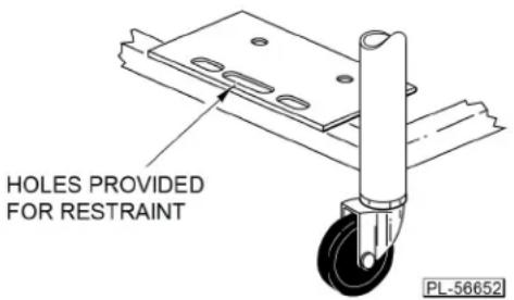
Fig. 1
If disconnection of the restraint is necessary, turn off the gas supply before disconnection. Reconnect this restraint prior to turning the gas supply on and prior to returning the braising pan to its originally installed position.
INSTALLATION CODES AND STANDARDS
Your Vulcan tilting braising pan must be installed in accordance with:
In the United States:
- State and local codes, or in the absence of local codes, with:
- National Fuel Gas Code ANSI-Z223.1 (latest edition), available from The American Gas Association, Inc., 1515 Wilson Boulevard, Arlington, VA 22209.
- National Electrical Code ANSI/NFPA-70 (latest edition).
- ANSI NFPA Standard #96 Vapor Removal from Cooking Equipment (latest edition), available from The National Fire Protection Association, Batterymarch Park, Quincy, MA 01169.
In Canada:
- Local codes.
- CAN/CGA-B149.1 National Fuel Gas Code (latest edition), available from The Canadian Gas Association, 178 Rexdale Boulevard, Etobicoke, Ontario, Canada M9W 1R3.
- Canadian Electrical Code Part 1 CSA-C22.1 (latest edition), available from The Canadian Standards Association, 178 Rexdale Boulevard, Etobicoke, Ontario, Canada M9W 1R3.
LEVELING AND ANCHORING THE TILTING BRAISING PAN
- Place the braising pan in the final installed position.
- Place a carpenter's level on the braising pan table top and turn the adjustable feet to level the braising pan table top side-to-side and front-to-back. Do not attempt to level the braising pan base.
- Mark hole locations on the floor through the anchoring holes provided in the rear, flanged adjustable feet.
- Remove the tilting braising pan from the installation location and drill holes in the locations marked on the floor. Insert proper anchoring devices (not supplied).
- Place the tilting braising pan back in the installation location.
- Place a carpenter's level on top of the braising pan, and re-level side-to-side and front-to-back.
- Bolt and anchor the tilting braising pan securely to the floor.
- Seal bolts and flanged feet with Silicon sealant or equivalent compound.
SERVICE CONNECTIONS
To access service and utility connections, remove the left side panel. To remove, hold the panel from underneath and lift it up. While holding the panel up, swing out the lower part of the panel until it clears the bottom flange and remove the panel. If required, the rear panel can also be removed using the same procedure.
The gas-powered braising pan is supplied with a 120-volt power cord.
The electrical connection for the electric braising pan can be accessed from the rear or the left panel.
GAS CONNECTIONS (See Fig. 2)
All gas supply connections and any pipe joint compound used must be resistant to the action of propane gases.
Connect a ^3/_4 " (nominal) gas supply to the braising pan. Recommended incoming gas line pressure is 7" W.C. (Water Column) (48.3 kPa) for natural gas or 11" W.C. (75.8 kPa) for propane gas.
Make sure the pipes are clean and free of obstructions, dirt and piping compound.
Codes require that a gas shutoff valve be installed in the gas line ahead of the tilting braising pan.
Natural gas and propane gas braising pans are equipped with fixed orifices, and no adjustment is necessary. The manifold is set at 3.7 W.C. (Water Column) (25.5 kPa) for natural gas and 10" W.C. (68.9 kPa) for propane gas.
⚠ WARNING Prior to lighting, check all joints in the gas supply line for leaks. Use soap and water solution. Do not use an open flame.
After piping has been checked for leaks, all piping receiving gas should be fully purged to remove air.
The electrical control circuit must be connected (see CONTROL CIRCUIT POWER CONNECTION in this manual).
TESTING THE GAS SUPPLY SYSTEM
When test pressures exceed 12 psig (3.45 kPa), the tilting braising pan and its individual shutoff valve must be disconnected from the gas supply piping system.
When test pressures are 12 psig (3.45 kPa) or less, the tilting braising pan must be isolated from the gas supply system by closing its individual manual shutoff valve.
VENTILATION
DO NOT obstruct the flow of flue gases from the flue duct located on the rear of the tilting braising pan. It is recommended that the flue gases be ventilated to the outside of the building through a ventilation system installed by qualified personnel.
From the termination of the braising pan flue vent to the filters of the hood venting system, an 18" (46 cm) minimum clearance must be maintained. The flue is not to be directly connected to the ventilation system.
Local jurisdictions may require a ventilation system to exhaust the steam from this appliance. Clearance should be provided for the lid to be raised without interference with the hood. A ceiling that is too low may not allow for an installation of a hood to meet this requirement.
CONTROL CIRCUIT POWER CONNECTION — GAS BRAISING PANS (See Fig. 2)
⚠ WARNING Appliances equipped with a flexible electric supply cord are provided with a three-prong grounding plug. It is imperative that this plug be connected into a properly grounded three-prong receptacle. If the receptacle is not the proper grounding type, contact an electrician. Do not remove the grounding prong from this plug.
ELECTRICAL CONNECTIONS (SEE FIG. 2)
⚠ WARNING Electrical and grounding connections must comply with the national electrical code and/or other local codes.
WARNING Disconnect the electrical power to the machine and follow lockout/tagout procedures.
The field connection box for field wire connection of Models VE30 and VE40 is located at the back of the braising pan. A knockout hole is provided for a 1" (2.5 cm) conduit connection.
- Remove the field connection box cover plate. Mount suitable 1" (2.5 cm) conduit fitting in the conduit opening provided on the bottom surface.
- Connect field wire to the terminal block as indicated on the wiring diagram. The wiring diagram is located on the inside of the field box lid. Wire must be of the type suitable for 75^ C service and at the suitable gauge for loads shown on the data plate.
- After making the connections, replace the control box cover plate.
- The braising pan must be grounded by installing a properly grounded lead to the ground lug located inside the field connection box.
ELECTRICAL DATA CHART
| Model Number | V (L-L) | Rated Line Current (A) | Rated Power (kW) | |||
| 3∅ 1∅ | ||||||
| L1 L2 L3 | ||||||
| VE30-FB | 208 33.3 | 33.3 | 33.3 | 57.7 | 12 | |
| 240 28.9 | 28.9 | 28.9 | 50.0 | 12 | ||
| 480 14.4 | 14.4 | 14.4 | - | 12 | ||
| VE40-FB | 208 45.9 | 41.6 | 45.9 | 76.9 | 16 | |
| 240 39.7 | 36.1 | 39.7 | 66.7 | 16 | ||
| 480 19.9 | 18.0 | 19.9 | - | 16 | ||
These values are nominal ratings. Field wire connections must be capable of withstanding anticipated surges.
SERVICE CONNECTIONS:
1. GAS BRAISING PAN:

GAS INPUT: 3/4" N.P.T., Nat.6"-14" W.C., propane gas 11"-18" W.C., See capacity chart.
ELECTRICAL: Machine is supplied with 120-VAC, 1-phase, 15-amp. power cord.
2. ELECTRICAL BRAISING PAN:

ELECTRICAL CONNECTION: 1" dia. conduit, fitting to be installed by installer.
IMPORTANT
- A pressure regulator sized for this unit is included. Natural gas 7" W.C., propane gas 11" W.C. supply pressure.
- Gas line connecting to appliance must be 34 " or larger. If flexible connectors are used, the inside diameter must be at least the same as the 34 " iron pipe.
- An adequate ventilation system is required for commercial cooking equipment. Information may be obtained by writing to the National Fire Protection Association, Batterymarch Park, Quincy, MA 02289. When writing, refer to NFPA No. 96.
- These units are manufactured for installation in accordance with ANSZ223.1A (latest edition), National Fuel Gas Code. Copies may be obtained from the American Gas Association, 1515 Wilson Blvd., Arlington, VA 22209.
- Clearances: Combustible Noncombustible Rear 6 6 Sides 2 0
- This appliance is manufactured for commercial installation only and is not intended for home use.
| MODEL | BTU/hr.Input |
| VG30 | 90,000 |
| VG40 | 120,000 |

| MODEL | 208 VAC | 240 VAC | 480 VAC |
| VE30 | 12 KW | 12 KW | 12 WK |
| VE40 | 16 KW | 16 KW | 16 KW |

| MODEL | Cooking 4 oz. Surface Area Capacity Portions | |
| VE/VG30 | 29" x 23" 30 gal./114 liters 960 | |
| VE/VG40 | 39" x 23" 40 gal./152 liters 1280 |
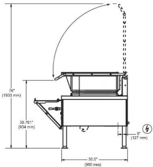
Fig. 2
OPERATION
⚠ WARNING The tilting braising pan and its parts are hot. Use care when operating, cleaning or servicing the braising pan.
BEFORE FIRST USE
Use a noncorrosive, grease-dissolving commercial cleaner to clean the protective metal oils from all surface parts and the interior of the tilting braising pan. Follow the cleaner manufacturer's directions. Rinse thoroughly and drain the pan. Wipe dry with a soft, clean cloth.
GAS HEAT BRAISING PANS
Controls (Fig. 3)
![THERMOSTAT VULCAN AMBER LIGHT ON / OFF SWITCH [O] = OFF [I] = ON MANUAL LIFT CRANK HANDLE OPTIONAL AUTOMATIC POWER LIFT RED HEAT L LIGHT PL-41750-1](/content/2026/05/891717/images/6df98985f99c6266655a11ca16ada0865df12bf273175d12d9cda7abab5f4b4c.jpg)
Fig. 3
Thermostat — Sets desired cooking temperature.
On/Off Switch (Black) — Turns the braising pan on and off.
Amber Light — When lit, indicates the machine is turned on.
Heat Light (Red) — When lit, indicates the thermostat is calling for heat.
Auto. Power Lift (Gray) — (Optional). Push the upper part of the switch to raise the braising pan; push the lower part to lower the braising pan. Always remove the manual lift crank handle before operating the automatic power lift.
Manual Lift Crank Handle — Use to manually raise and lower the braising pan.
Lighting and Shutdown of Pilot
Lighting instructions are also located on the front panel.
- Turn main gas supply to the braising pan to the ON position at the shutoff valve.
- Lower the braising pan (see OPERATION OF LIFTING SYSTEM in this manual). The braising pan will not operate with the pan in the UP position (5 degrees or higher from horizontal).
- Turn the black on/off switch to the ON position. The ON position is indicated by a glowing amber light on the control panel.
- Turn the thermostat to the desired cooking temperature.
- If pilot is extinguished, turn the gas supply and the on/off switch to the OFF position. Wait 5 minutes before relighting.
Nightly Shutdown
Turn the on/off switch to the OFF position.
Extended Shutdown
Turn the on/off switch to the OFF position and turn off the gas supply.
Operating the Gas Braising Pan
The braising pan does not require any adjustments before startup.
The entire flue duct opening (located across the rear of the braising pan) must be left uncovered.
Turn the on/off switch to the ON position and turn the thermostat to the desired temperature to put the braising pan into operation.
To prevent discoloration of the stainless steel cooking surface, do not turn the heat on unless the braising pan is covered with a fluid, a thin layer of cooking oil or food to be cooked.
DO NOT use the braising pan as a deep fat fryer; use it only for shallow pan frying (cooking oil film not more than 18 " [0.3 cm] thick). Its use for deep frying could result in a fire hazard. See SUGGESTED USES FOR YOUR BRAISING PAN in this manual for additional information.
Do not overheat the clad stainless steel plate by setting the temperature well above recommended temperatures or by operating the braising pan without any fluid inside the pan to absorb heat. Overheating the plate may cause warping and will carbonize any cooking oil on the plate and cause sticking.
In case of a power failure, there will be no flames because the combination control valve will shut off the gas flow. In the event of a power failure, immediately turn the on/off switch to the OFF position. Once power is restored, turn the on/off switch to the ON position to resume cooking.
The lid is spring-loaded and will stay in any position at which it is placed. After some time, the springs may need to be tightened. Call your local Vulcan-authorized servicer to make these adjustments.
ELECTRIC HEAT BRAISING PANS
Controls (see Fig. 3)
Thermostat — Sets desired cooking temperature.
On/Off Switch (Black) — Turns the braising pan on and off.
Amber Light — When lit, indicates the machine is turned on.
Heat Light (Red) — When lit, indicates the thermostat is calling for heat.
Auto. Power Lift (Gray) — (Optional). Push the upper part of the switch to raise the braising pan; push the lower part to lower the braising pan. Always remove the manual lift crank handle before operating the automatic power lift.
Manual Lift Crank Handle — Use to manually raise and lower the braising pan.
Operating the Electric Braising Pan
The braising pans do not require any adjustments before startup.
Turn the black on/off switch to the ON position.
Lower the braising pan (see OPERATION OF LIFTING SYSTEM in this manual). The braising pan will not operate with the pan in the UP position (5 degrees or higher from horizontal).
Turn the thermostat to the desired cooking temperature.
To prevent discoloration of the stainless steel cooking surface, do not turn the heat on unless the braising pan surface is covered with a fluid, a thin layer of cooking oil or food to be cooked.
DO NOT use the braising pan as a deep fat fryer; use it only for shallow pan frying (cooking oil film not more than 18 " [0.3 cm] thick). Its use for deep frying could result in a fire hazard. See SUGGESTED USES FOR YOUR BRAISING PAN in this manual for additional information.
Do not overheat the clad stainless steel plate by setting the temperature well above recommended temperatures or by operating the braising pan without any fluid inside the pan to absorb heat. Overheating the plate may cause warping and will carbonize any cooking oil on the plate and cause sticking.
The lid is spring-loaded and will stay in any position at which it is placed. After some time, the springs may need to be tightened. Call your local Vulcan-authorized servicer to make these adjustments.
Keep the area underneath and around the braising pan clear of your hands or any other objects when operating the lifting system.
Do not obstruct any of the moving parts of the lift system located underneath the table top on the right and/or left side of the braising pan. This area must be kept clear of any objects or obstructions at all times.
Do not leave the braising pan in the UP position for extended periods (e.g., overnight or during a shutdown period between cooking times).
Braising Pans with Manual Lift (Standard)
- The crank for the manual lift system is shipped separately.
- There are two pins on one end of the crank. Insert the crank through the hole on the control panel so that the two pins engage in the slots of the speed reducer coupling located behind the panel.
- Turn the crank handle clockwise to lift the braising pan and counterclockwise to lower the braising pan.
- This lift system is not affected by a power failure and can be operated during a power failure.
- Refer to the MAINTENANCE section of this manual for lubrication and maintenance instructions.
Braising Pans with Automatic Power Lift (Optional)
- The automatic lift cannot raise the braising pan unless the lid is fully opened.
- The pan lift is controlled by the gray rocker switch located on the control panel (see Fig. 3).
- Always remove the manual crank handle before operating the automatic power lift.
- Press the upper half of the gray rocker switch to raise the braising pan and the lower half of the gray rocker switch to lower the braising pan. The switch must be held for continuous raising or lowering of the braising pan.
- In case of a power failure, use the hand crank (shipped separately) to lower or raise the pan (same as the braising pans with manual lift).
UNLOADING PREPARED FOODS
All braising pans are provided with a frame support (Fig. 4) for holding a food receiving pan when unloading prepared foods.
Pull the frame support out and up until it locks. The support will accept food receiving pans of 12" x 20" (30 cm x 50 cm) up to 6" (15 cm) deep.
When lowering the frame support, push in on the hinges until they bend, then lower the support.
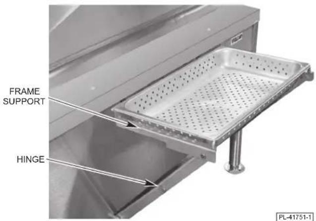
Fig. 4
STEAMING INSERTS (Optional)
Your tilting braising pan can be used for steaming frozen and fresh foods. The 30-gallon (114 L) pans (Models VE30 or VG30) can be loaded with a maximum of two 12" x 20" x 4" (30 cm x 50.8 cm x 10 cm) deep steaming pans. The 40-gallon (151 L) pan (Models VE40 or VG40) will accept up to three steam pans of this same size.
To use the braising pan for steaming, fill the pan with 6 to 7 gallons (23 to 26 L) of water (approximately 2" [5 cm] deep) for 30-gallon (114 L) models and 8 to 9 gallons (30 to 34 L) of water (approximately 2" [5 cm] deep) for 40-gallon (151 L) models.
Turn the braising pan ON. Set the thermostat at 212^ F ( 100^ C). Allow the water to come to a boil. Then change the thermostat setting to 250^ F ( 121^ C) and carefully place the steaming inserts into the pan as shown in Fig. 5. Place the pan with product into the steaming insert. Close the lid and allow steaming for the desired time.
Periodically inspect the water level inside the braising pan. Add water if the water level is less than 12 " (1 cm) deep.
To use the braising pan as a food warmer or bain marie, follow the same procedure as for steaming, but increase the depth of the water to allow the bottom and part of the sides of the steaming inserts to be immersed in water. Set the thermostat for the holding or warming temperature desired.
The steaming inserts can be ordered from your dealer.

Fig. 5
SUGGESTED USES FOR YOUR BRAISING PAN
DO NOT use the braising pan for deep fat frying. Restrict frying activity to shallow pan frying (oil film not more than 18 " [0.3 cm] thick) or sautéing.
A tilting braising pan is quite versatile. It can be used for roasting, simmering, boiling, sautéing, searing, frying, warming, holding, proofing, thawing, browning, steaming, braising, griddling or stewing. It can be used as an oversized skillet, as a bain marie, as a proofing oven, as a stock pot, as a kettle or as an even-heat range top. It can be used for cooking breakfasts, lunches and dinners.
Your Vulcan tilting braising pan is a multi-purpose unit that can be used for virtually any type of cooking, except deep fat frying, with great speed, in large volume and with considerable savings in labor and energy.
STAINLESS STEEL EQUIPMENT CARE AND CLEANING
(Supplied courtesy of NAFEM. For more information, visit their web site at www.nafem.org)
Contrary to popular belief, stainless steels ARE susceptible to rusting.
Corrosion on metals is everywhere. It is recognized quickly on iron and steel as unsightly yellow/orange rust. Such metals are called “active” because they actively corrode in a natural environment when their atoms combine with oxygen to form rust.
Stainless steels are passive metals because they contain other metals, like chromium, nickel and manganese that stabilize the atoms. 400 series stainless steels are called ferritic, contain chromium, and are magnetic; 300 series stainless steels are called austenitic, contain chromium and nickel; and 200 series stainless, also austenitic, contains manganese, nitrogen and carbon. Austenitic types of stainless are not magnetic, and generally provide greater resistance to corrosion than ferritic types.
With 12-30 percent chromium, an invisible passive film covers the steel's surface acting as a shield against corrosion. As long as the film is intact and not broken or contaminated, the metal is passive and stainless. If the passive film of stainless steel has been broken, equipment starts to corrode. At its end, it rusts.
Enemies of Stainless Steel
There are three basic things which can break down stainless steel's passivity layer and allow corrosion to occur.
- Mechanical abrasion
- Deposits and water
- Chlorides
Mechanical abrasion means those things that will scratch a steel surface. Steel pads, wire brushes and scrapers are prime examples.
Water comes out of the faucet in varying degrees of hardness. Depending on what part of the country you live in, you may have hard or soft water. Hard water will leave spots, and when heated leave deposits behind that if left to sit, will break down the passive layer and rust stainless steel. Other deposits from food preparation and service must be properly removed.
Chlorides are found nearly everywhere. They are in water, food and table salt. One of the worst chloride perpetrators can come from household and industrial cleaners.
So what does all this mean? Don't Despair!
Here are a few steps that can help prevent stainless steel rust.
1. Use the proper tools.
When cleaning stainless steel products, use non-abrasive tools. Soft cloths and plastic scouring pads will not harm steel's passive layer. Stainless steel pads also can be used but the scrubbing motion must be in the direction of the manufacturers' polishing marks.
2. Clean with the polish lines.
Some stainless steel comes with visible polishing lines or “grain.” When visible lines are present, always scrub in a motion parallel to the lines. When the grain cannot be seen, play it safe and use a soft cloth or plastic scouring pad.
3. Use alkaline, alkaline chlorinated or non-chloride containing cleaners.
While many traditional cleaners are loaded with chlorides, the industry is providing an ever-increasing choice of non-chloride cleaners. If you are not sure of chloride content in the cleaner used, contact your cleaner supplier. If your present cleaner contains chlorides, ask your supplier if they have an alternative. Avoid cleaners containing quaternary salts; it also can attack stainless steel and cause pitting and rusting.
4. Treat your water.
Though this is not always practical, softening hard water can do much to reduce deposits. There are certain filters that can be installed to remove distasteful and corrosive elements. To insure proper water treatment, call a treatment specialist.
5. Keep your food equipment clean.
Use alkaline, alkaline chlorinated or non-chloride cleaners at recommended strength. Clean frequently to avoid build-up of hard, stubborn stains. If you boil water in stainless steel equipment, remember the single most likely cause of damage is chlorides in the water. Heating cleaners that contain chlorides have a similar effect.
6. Rinse, rinse, rinse.
If chlorinated cleaners are used, rinse and wipe equipment and supplies dry immediately. The sooner you wipe off standing water, especially when it contains cleaning agents, the better. After wiping equipment down, allow it to air dry; oxygen helps maintain the stainless steel's passivity film.
7. Never use hydrochloric acid (muriatic acid) on stainless steel.
8. Regularly restore/passivate stainless steel.
| Job Cleaning Agent | Comments | |
| Routine cleaning Soap, ammonia, detergent, Medallion | Apply with soft cloth or sponge. | |
| Fingerprints and smears Arcal 20, Lac-O-Nu Ecoshine Provides b | barrier film | |
| Stubborn stains and discoloration | Cameo, Talc, Zud, First Impression | Rub in direction of polish lines. |
| Grease and fatty acids, blood, burnt-on foods | Easy-off, DeGrease It Oven Aid | Excellent removal on all finishes |
| Grease and Oil Any good commercial detergent | Apply with soft cloth or sponge. | |
| Restoration/Passivation Benefit, Super Sheen, Wichinox | ||
Review
- Stainless steels rust when passivity (film-shield) breaks down as a result of scrapes, scratches, deposits and chlorides.
- Stainless steel rust starts with pits and cracks.
- Use the proper tools. Do not use steel pads, wire brushes or scrapers to clean stainless steel.
- Use non-chlorinated cleaners at recommended concentrations. Use only chloridefree cleaners.
- Soften your water. Use filters and softeners whenever possible.
- Wipe off cleaning agent(s) and standing water as soon as possible. Prolonged contact causes eventual problems.
To learn more about chloride-stress corrosion and how to prevent it, contact the equipment manufacturer or cleaning materials supplier.
Developed by Packer Engineering, Naperville, Ill., an independent testing laboratory.
CLEANING
⚠ WARNING Disconnect the electrical power to the machine and follow lockout / tagout procedures before cleaning.
Clean your braising pan regularly. Keep the plate surface clean. To produce evenly cooked, perfectly braised products, keep the pan surface free from carbonized grease. Carbonized grease on the surface hinders the transfer of heat from the pan surface to the food. This results in spotty browning and loss of cooking efficiency. Worst of all, carbonized grease tends to cling to the foods, giving them a highly unsatisfactory and unappetizing appearance.
After Each Use
Clean the pan surface with a brush or flexible spatula.
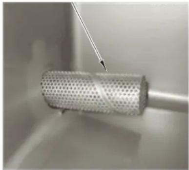
Remove the strainer (Fig. 6) at the pouring lip of the braising pan by pulling it toward the back of the pan. Clean the strainer in a sink. Rinse thoroughly and dry with a soft, clean cloth. Replace strainer (Fig 6).

natural_image
Close-up of a perforated metal component with a cylindrical base, no visible text or symbolsFig. 6
Once A Day:
Thoroughly clean the back, sides and front of the pan. Also clean the inside and outside surfaces of the lid.
Once A Week:
Clean the pan surface thoroughly. If necessary, use a griddle stone or brush on the surface. A detergent may be used on the pan surface to help clean it, but be sure the detergent is thoroughly removed.
Clean other stainless steel surfaces with a damp cloth and polish with a soft, dry cloth. To remove discolorations, use a nonabrasive cleaner. If the braising pan usage is very high, consider going through the weekly cleaning procedures more often than once a week.
When cleaning the braising pan, it is helpful to fill the pan with approximately 10 gallons (38 L) of warm water and add detergent. After cleaning, raise the braising pan to drain all water (place a bucket or container under the pouring lip). Then repeat the procedures for rinsing with clean water.
COMPRESSION DRAW-OFF VALVE CLEANING INSTRUCTIONS
Daily After Use
Remove draw-off valve stem assembly for cleaning (Fig. 7).
- Turn the valve handle counterclockwise until it stops.
- Pull the valve handle back until it stops.
- Turn large hex nut counterclockwise until the valve stem assembly is loose.
- Pull the assembly straight out of the valve body.
- Remove wing nut and handle. Unscrew valve stem from bonnet.
- Wash valve body and stem assembly with mild soap and water, and then rinse. Make sure all food residue is removed from inside valve body.
- Leave assembly apart to air dry.
Install draw-off valve assembly:
-
Apply Petrol-Gel lubricant to valve stem threads, O-Ring, rubber plug face and large hex nut threads.
-
Thread the valve stem into bonnet till valve stem can be pulled through bonnet.
-
Insert valve stem into valve body.
-
Install large hex nut hand tight.
-
Install valve handle, lock washer and wing nut onto the valve stem.
-
Turn valve handle clockwise until closed. Do not overtighten.
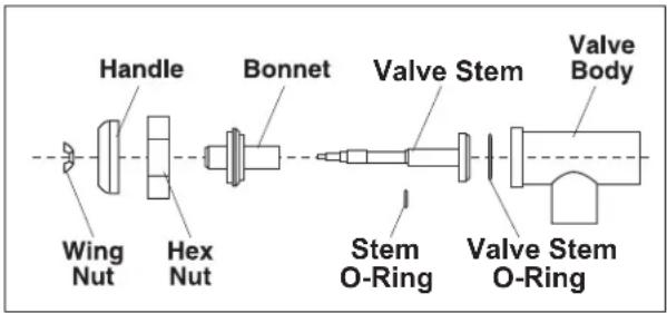
Fig. 7
PROPER STRAINER INSTALLATION FOR DRAW-OFF VALVE
natural_image
Close-up of a perforated cylindrical object with a pointed tip, placed on a surface (no text or symbols visible)Fig. 8
COOKING GUIDELINES (Domestic Measurements)
The guidelines given below are suggested quantities, temperature settings and estimated numbers of orders per load and per hour. When two temperatures are given, the first is to start the product and the second is to finish the product.
The following temperatures should be used:
Temperature
(°F)
Simmering 200 Max.
Sautéing 225 to 275
Searing 300 to 350
Frying 325 to 375
Grilling 350 to 425
| PORTION SIZE | TEMP. (°F) | BATCHES PER HOUR | VG30/VE30 PER LOAD QTY. PORTIONS QTY. PORTIONS | VG40/VE40 PER LOAD |
BREAKFAST FOODS
| Bacon 3 Slices 350 12 2 lb. 10 | 3 lb. | 15 | |||||
| Eggs | |||||||
| -Boiled-Hard | 1 egg | 225 | 5 | 50 eggs | 50 | 75 eggs | 75 |
| -Boiled-Soft | 1 egg | 225 | 8 | 50 eggs | 50 | 75 eggs | 75 |
| -Fried | 1 egg | 400 | 4 | 30 eggs | 30 | 45 eggs | 45 |
| -Poached | 1 egg | 225 | 5 | 36 eggs | 36 | 60 eggs | 60 |
| -Scrambled | 1^1/_2 eggs | 300 – 200 | 1 | 18 gal. | 720 | 28 gal. | 1100 |
| French Toast | 3 slices | 425 | 7 | 35 slices | 12 | 50 slices | 17 |
| Regular Oatmeal | ^1/_2 cup | 250 | 2 | 20 lb (100 cups) | 500 | 40 lb (200 cups) | 1000 |
| Pancakes | 2 each | 400 | 10 | 30 ea. | 15 | 50 ea. | 25 |
FISH
| Clams | 1 pt. | 400 | 10 | 10 qts. | 20 | 15 qts. | 30 |
| Fish Cakes | 2 to 3 oz. | 400 | 5 | 70 – 3 oz. | 35 | 110 – 3 oz. | 55 |
| Haddock Fillet | 4 oz. | 400 | 4 | 60 – 4 oz. | 60 | 90 – 4 oz. | 90 |
| Halibut Steak | 5 oz. | 425 | 3 | 60 – 4 oz. | 60 | 90 – 4 oz. | 90 |
| Lobster | 1 – 1 lb. | 350 | 4 | 20 – 1 lb. | 20 | 30 – 1 lb. | 30 |
| Swordfish | 5 oz. | 425 | 3 | 50 – 5 oz. | 50 | 75 – 5 oz. | 75 |
SAUCES, GRAVIES, SOUPS
| Brown Gravy | 1 oz. | 350 – 200 | 2 | 30 gal. | 3840 | 40 gal. | 5120 |
| Cream Sauce | 2 oz. | 250 – 175 | 1 | 30 gal. | 1920 | 40 gal. | 2560 |
| Cream Soup | 6 oz. | 200 | 1 | 30 gal. | 640 | 40 gal. | 853 |
| French Onion Soup | 6 oz. | 225 | 1 | 30 gal. | 640 | 40 gal. | 853 |
| Meat Sauce | 4 oz. | 350 – 200 | 1 | 30 gal. | 960 | 40 gal. | 1280 |
| PORTION SIZE | TEMP. (°F) | BATCHES PER HOUR | VG30/VE30 PER LOAD QTY. PORTIONS QTY. PORTIONS | VG40/VE40 PER LOAD QTY. PORTIONS QTY. PORTIONS |
VEGETABLES
CANNED 3 oz. 400 6 30 lb. 125 45 lb. 200
FRESH
Beans, Wax, Green 3 oz. 400 3 25 lb. 125 50 lb. 250
Beets 3 oz. 400 1 30 lb. 125 60 lb. 300
Broccoli 3 oz. 400 3 25 lb. 125 40 lb. 200
Cabbage 3 oz. 400 5 20 lb. 80 30 lb. 125
Carrots 3 oz. 400 2 35 lb. 150 70 lb. 300
Cauliflower 3 oz. 250 5 15 lb. 75 25 lb. 125
| Corn | 1 Ear | 400 | 8 | 50 ears | 50 | 75 ears | 75 |
| Potatoes | 3 oz. | 400 2 40 lb. | 200 60 lb. | 300 | |||
| Spinach | 4 oz. | 250 | 10 | 6 lb. | 25 | 9 lb. | 35 |
Turnips 4 oz. 400 2 20 lb. 100 30 lb. 150
FROZEN
| Beans, French Green | 3 oz. 400 6 15 lb. 60 | 22 | ^1/_2 lb. | 90 | ||
| Lima Beans | 3 oz. 250 4 15 lb. 60 | 22 | ^1/_2 lb. | 90 | ||
| Broccoli 3 oz. 400 8 12 lb. 50 18 lb. 75 | ||||||
| Sliced Carrots | 3 oz. 250 6 15 lb. 60 | 22 | ^1/_2 lb. | 90 | ||
| Small Whole Carrots | 3 oz. 250 3 15 lb. 50 | 22 | ^1/_2 lb. | 90 | ||
| Corn | 3 oz. 250 | 18 | 15 lb. | 50 | 22^1/_2 lb. | 90 |
| Small Whole Onions | 3 oz. 250 7 15 lb. 50 | 22 | ^1/_2 lb. | 90 | ||
| Peas | 3 oz. 400 | 10 | 15 lb. | 75 | 22^1/_2 lb. | 110 |
| Spinach | 3 oz. 400 3 15 lb. 75 | 22 | ^1/_2 lb. | 110 | ||
DESSERTS, PUDDINGS, SWEET SAUCES
| Butterscotch Sauce | 1 oz. | 200 | 1 | 30 gal. | 3840 | 40 gal. | 5120 |
| Cherry Cobbler | 3 oz. | 200 | 1 | 30 gal. | 1280 | 40 gal. | 1707 |
| Chocolate Sauce | 1 oz. | 200 | 1 | 30 gal. | 3840 | 40 gal. | 5120 |
| Cornstarch Pudding | 4 oz. | 200 | 1 | 30 gal. | 960 | 40 gal. | 1280 |
| Fruit Gelatin | 3 oz. | 250 | 2 | 30 gal. | 1280 | 40 gal. | 1707 |
MEAT - POULTRY
| Bacon | 3 Slices | 350 | 12 | 2 lb. | 10 | 3 lb. | 15 |
| BEEF | |||||||
| Amer. Chop Suey | 6 oz. | 400 – 225 | 2 | 30 gal. | 640 | 40 gal. | 853 |
| Beef Stew | 8 oz. | 300 | — | 30 gal. | 480 | 40 gal. | 640 |
| Corned Beef Hash | 5 oz. | 400 5 20 lb. | 60 30 lb. | 90 | |||
| Cheeseburger | 3 oz. | 300 | 12 | 7 lb. | 35 | 10 lb. | 50 |
| Hamburger | 3 oz. | 300 | 15 | 7 lb. | 35 | 10 lb. | 50 |
| Meatballs | 1 oz. | 400 – 225 | 3 | 12^1/2 lb. | 65 18 lb. | 100 | |
| Pot Roast | 2 oz. | 350 – 200 | 120 lb. | 500 | 180 lb. | 750 | |
| Salisbury Steak | 5 oz. | 400 3 16 lb. | 50 24 lb. | 75 | |||
| Sirloin Steak | 6 oz. | 400 5 15 lb. | 40 | 22 | ^1/2 lb. | 60 | |
| Swiss Steak | 4 oz. | 300 – 200 | 1 | 25 lb. | 110 | 40 lb. | 160 |
| PORTION | TEMP. | BATCHES | VG30/VE30 | VG40/VE40 | |
| PER | PER LOAD | PER LOAD | |||
| ITEM | SIZE | (°F) | HOUR | QTY. PORTIONS QTY. PORTIONS | |
CHICKEN
Pan Fried 2 – 14 's 350 3 50 pieces 25 80 pieces 40
Whole 2 oz. 350 – 200 16 – 5 lb. 200 24 – 5 lb. 265
FRANKFURTERS
| Grilled | 2 oz. | 300 | 8 | 22 lb. | 176 | 33 lb. | 264 |
| Boiled | 2 oz. | 250 | 12 | 16 lb. | 128 | 25 lb. | 200 |
PORK
| Ham Steak | 3 oz. | 400 | 8 | 10 lb. | 50 | 15 lb. | 75 |
| Pork Chops | 5 oz. | 350 | 4 | 15 lb. | 50 | 25 lb. | 75 |
| Sausage Links | 3 links | 350 | 7 | 30 lb. | 120 | 45 lb. | 180 |
TURKEY
| Off Carcass | 2 oz. | 400 – 200 | — | 3–26 to 30 lb. | 200 | 4–26 to 30 lb. | 275 |
| On Carcass | 2 oz. | 400 – 200 | — | 4–16 to 20 lb. | 175 | 6–16 to 20 lb. | 265 |
MISCELLANEOUS
| Grilled Cheese Sandwich | 1 sand. | 400 | 8 | 40 sand. | 40 | 50 sand. | 50 |
| Macaroni & Cheese | 8 oz. | 200 | 2 | 30 gal. | 480 | 40 gal. | 640 |
| Rice | 4 oz. | 350 – 225 | 1 | 20 lb. raw | 320 | 40 lb. raw | 650 |
| Spaghetti | 4 oz. | 350 – 225 | 2 | 8 lb. raw | 200 | 12 lb. raw | 300 |
COOKING GUIDELINES (Metric Measurements)
The guidelines given below are suggested quantities, temperature settings and estimated numbers of orders per load and per hour. When two temperatures are given, the first is to start the product and the second is to finish the product.
The following temperatures should be used:
Temperature (°C)
Simmering 93.3 Max.
Sautéing 107 to 135
Searing 149 to 177
Frying 163 to 191
Grilling 177 to 218
| ITEM | PORTION SIZE | TEMP. (°C) | BATCHES PER HOUR | VG30/VE30 PER LOAD QTY. PORTIONS QTY. PORTIONS | VG40/VE40 PER LOAD | ||
| BREAKFAST FOODS | |||||||
| Bacon | 3 Slices | 177 | 12 | 0.9 kg | 10 | 1.4 kg | 15 |
| Eggs | |||||||
| -Boiled-Hard | 1 egg | 107 | 5 | 50 eggs | 50 | 75 eggs | 75 |
| -Boiled-Soft | 1 egg | 107 | 8 | 50 eggs | 50 | 75 eggs | 75 |
| -Fried | 1 egg | 204 | 4 | 30 eggs | 30 | 45 eggs | 45 |
| -Poached | 1 egg | 107 | 5 | 36 eggs | 36 | 60 eggs | 60 |
| -Scrambled | 1^1/_2 eggs | 149 – 93 | 1 | 68 L | 720 | 106 L | 1100 |
| French Toast | 3 slices | 218 | 7 | 35 slices | 12 | 50 slices | 17 |
| Regular Oatmeal | 118 mL | 121 | 2 | 9 kg | 500 | 18 kg | 1000 |
| Pancakes | 2 each | 204 | 10 | 30 ea. | 15 | 50 ea. | 25 |
| FISH | |||||||
| Clams | 473 mL | 204 | 10 | 9 L | 20 | 14 L | 30 |
| Fish Cakes | 57 to 85 g | 204 | 5 | 70 – 85 g | 35 | 110 – 85 g | 55 |
| Haddock Fillet | 113 g | 204 | 4 | 60 – 113 g | 60 | 90 – 113 g | 90 |
| Halibut Steak | 142 g | 218 | 3 | 60 – 113 g | 60 | 90 – 113 g | 90 |
| Lobster | 1 – 0.5 kg | 177 | 4 | 20 – 0.5 kg | 20 | 30 – 0.5 kg | 30 |
| Swordfish | 142 g | 218 | 3 | 50 – 142 g. | 50 | 75 – 142 g | 75 |
| SAUCES, GRAVIES, SOUPS | |||||||
| Brown Gravy | 28 g | 177 – 93 | 2 | 114 L | 3840 | 151 L | 5120 |
| Cream Sauce | 57 g | 121 – 79 | 1 | 114 L | 1920 | 151 L | 2560 |
| Cream Soup | 170 g | 93 | 1 | 114 L | 640 | 151 L | 853 |
| French Onion Soup | 170 g | 107 | 1 | 114 L | 640 | 151 L | 853 |
| Meat Sauce | 113 g | 177 – 93 | 1 | 114 L | 960 | 151 L | 1280 |
| PORTION | TEMP. | BATCHES PER HOUR | VG30/VE30 PER LOAD QTY. PORTIONS QTY. PORTIONS | VG40/VE40 PER LOAD QTY. PORTIONS QTY. PORTIONS | |
| ITEM | SIZE | (°C) |
VEGETABLES
CANNED 85 g 204 6 14 kg 125 20 kg 200
FRESH
Beans, Wax, Green 85 g 204 3 11 kg 125 23 kg 250
| Beets | 85 g 204 1 14 kg 125 27 kg 300 | ||||||
| Broccoli | 85 g 204 3 11 kg 125 18 kg 200 | ||||||
| Cabbage | 85 g | 204 | 5 | 9 kg | 80 | 14 kg | 125 |
| Carrots | 85 g 204 2 16 kg 150 32 kg 300 | ||||||
| Cauliflower | 85 g | 121 | 5 | 7 kg | 75 | 11 kg | 125 |
| Corn | 1 Ear | 204 | 8 | 50 ears | 50 | 75 ears | 75 |
| Potatoes | 85 g 204 2 18 kg 200 27 kg 300 | ||||||
| Spinach | 113 g | 121 | 10 | 3 kg | 25 | 4 kg | 35 |
| Turnips | 113 g | 204 | 2 | 9 kg | 100 | 14 kg | 150 |
FROZEN
| Beans, French Green | 85 g | 204 | 6 | 7 kg | 60 | 10 kg | 90 |
| Lima Beans | 85 g | 121 | 4 | 7 kg | 60 | 10 kg | 90 |
| Broccoli | 85 g | 204 | 8 | 5 kg | 50 | 8 kg | 75 |
| Sliced Carrots | 85 g | 121 | 6 | 7 kg | 60 | 10 kg | 90 |
| Small Whole Carrots | 85 g | 121 | 3 | 7 kg | 50 | 10 kg | 90 |
| Corn | 85 g | 121 | 18 | 7 kg | 50 | 10 kg | 90 |
| Small Whole Onions | 85 g | 121 | 7 | 7 kg | 50 | 10 kg | 90 |
| Peas | 85 g | 204 | 10 | 7 kg | 75 | 10 kg | 110 |
| Spinach | 85 g | 204 | 3 | 7 kg | 75 | 10 kg | 110 |
DESSERTS, PUDDINGS, SWEET SAUCES
| Butterscotch Sauce | 28 g | 93 | 1 | 114 L | 3840 | 151 L | 5120 |
| Cherry Cobbler | 85 g | 93 | 1 | 114 L | 1280 | 151 L | 1707 |
| Chocolate Sauce | 28 g | 93 | 1 | 114 L | 3840 | 151 L | 5120 |
| Cornstarch Pudding 113 g 93 | 1 114 L 960 151 L | 1280 | |||||
| Fruit Gelatin | 85 g | 121 | 2 | 114 L | 1280 | 151 L | 1707 |
MEAT - POULTRY
| Bacon | 3 Slices | 177 | 12 | 0.9 kg | 10 | 1 kg | 15 |
| BEEF | |||||||
| Amer. Chop Suey | 170 g | 204 – 107 | 2 | 114 L | 640 | 151 L | 853 |
| Beef Stew | 0.2 kg | 149 | — | 114 L | 480 | 151 L | 640 |
| Corned Beef Hash | 142 g | 204 | 5 | 9 kg | 60 | 14 kg | 90 |
| Cheeseburger | 85 g | 149 | 12 | 3 kg | 35 | 5 kg | 50 |
| Hamburger | 85 g | 149 | 15 | 3 kg | 35 | 5 kg | 50 |
| Meatballs | 28 g | 204 – 107 | 3 | 6 kg | 65 | 8 kg | 100 |
| Pot Roast | 57 g | 177 – 93 | 54 kg | 500 | 82 kg | 750 | |
| Salisbury Steak | 142 g | 204 | 3 | 7 kg | 50 | 11 kg | 75 |
| Sirloin Steak | 170 g | 204 | 5 | 7 kg | 40 | 10 kg | 60 |
| Swiss Steak | 113 g | 149 – 93 | 1 | 11 kg | 110 | 18 kg | 160 |
| PORTION | TEMP. | BATCHES PER HOUR | VG30/VE30 PER LOAD QTY. PORTIONS QTY. PORTIONS | VG40/VE40 PER LOAD QTY. PORTIONS QTY. PORTIONS | |
| ITEM | SIZE | (°C) |
CHICKEN
Pan Fried 2 – 14 's 177 3 50 pieces 25 80 pieces 40
Whole 57 g 177 – 93 16 – 2 kg 200 24 – 2 kg 265
FRANKFURTERS
| Grilled | 57 g | 149 | 8 | 10 kg | 176 | 15 kg | 264 |
| Boiled | 57 g | 121 | 12 | 7 kg | 128 | 11 kg | 200 |
PORK
| Ham Steak | 85 g | 204 | 8 | 5 kg | 50 | 7 kg | 75 |
| Pork Chops | 142 g | 177 | 4 | 7 kg | 50 | 11 kg | 75 |
| Sausage Links | 3 links | 177 | 7 | 14 kg | 120 | 10 kg | 180 |
TURKEY
| Off Carcass | 57 g | 204 – 93 | — | 3 – 12 to 14 kg | 200 | 4 – 12 to 14 kg | 275 |
| On Carcass | 57 g | 204 – 93 | — | 4 – 7 to 9 kg | 175 | 6 – 7 to 9 kg | 265 |
MISCELLANEOUS
| Grilled Cheese Sandwich | 1 sand. | 204 | 8 | 40 sand. | 40 | 50 sand. | 50 |
| Macaroni & Cheese | 0.2 kg | 93 | 2 | 114 L | 480 | 151 L | 640 |
| Rice | 113 g | 177 – 107 | 1 | 9 kg raw | 320 | 18 kg raw | 650 |
| Spaghetti | 113 g | 177 – 107 | 2 | 4 kg raw | 200 | 5 kg raw | 300 |
MAINTENANCE
⚠ WARNING The tilting braising pan and its parts are hot. Use care when operating, cleaning or servicing the braising pan.
⚠ WARNING Disconnect the electrical power to the machine and follow lockout/tagout procedures before performing any maintenance.
LUBRICATION
Lid Mechanism
- The lid lift mechanism and tension spring are located behind the backsplash (sheet metal panel behind the braising pan) on both the left and right rear corners of the braising pan.
- Take the cover off by prying and lifting up (Fig. 9).
- For smooth operation of the lid, lubricate these mechanisms with 8 to 10 drops of lubricating machine oil every 6 months. Place a few drops of oil between the lid arm and stationary block, and a few drops on the shaft around which the spring is coiled.
- Replace the cover to maintain smooth operation.

Fig. 9
ADJUSTMENTS
At least twice a year, have a Vulcan authorized service person clean and adjust the tilting braising pan for maximum performance.
FLUE
When cool, annually check the flue. Clean the flue of any grease buildup or other obstructions that can affect the flow of the flue gases from the braising pan.
SERVICE AND PARTS INFORMATION
To obtain service and parts information concerning the tilting braising pan, contact the Vulcan service agency in your area (refer to listing supplied with the braising pan) or Vulcan service department at the address or phone number shown on the front cover of this manual.
TROUBLESHOOTING
GAS HEAT BRAISING PANS
| Problem Possible Cause | |
| Burners do not come on. 1. The power supply is off.2. The gas supply to the braising pan is off.3. The thermostat is not turned on.4. The gas valve is off.5. The pan is not in the lowest position.6. Problem with the gas control system. Contact your Vulcan authorized servicer. | |
| Burners produce carbon deposits. | 1. Braising pan frame is not level.2. Wrong size orifices.3. Burner air is not adjusted properly.4. Wrong gas supply5. Incorrect pressure at supply. |
ELECTRIC HEAT BRAISING PANS
| Problem Possible Cause | |
| Heating elements do not come on. | 1. The power supply is off.2. The thermostat is not turned on.3. Blown fuse in field electrical box.4. Pan is not in the lowest position.5. Problem with the control circuits. Contact your Vulcan authorized servicer. |

natural_image
Black-and-white photo of a technician in a cap and glasses working on machinery, no visible text or symbolsFREE Vulcan & Wolf New Equipment Checkout
A PARTNERSHIP WITH HOBART & AUTHORIZED WARRANTY SERVICE PROVIDERS
To ensure new Vulcan and Wolf equipment has been properly installed and is operating correctly, an authorized service technician will:
- Verify that the proper gas type (LP or natural) has been connected to the equipment
■ Verify that the proper voltage and electrical connections have been made - Verify that proper pressure regulators have been installed and adjusted, when applicable
- Verify that gas supply size and pressure are adequate
- Verify that proper water, steam, drain supplies and connections have been made
-
Check to ensure the ventilation system is operating correctly
-
Check pilot and burner adjustments
- Verify thermostat operation, including calibration, when required
- Check functional parts of operation, for example: doors, lids, valves, etc.
■ Advise on preventive maintenance procedures
■ Equipment must be completely installed and ready to operate before the equipment checkout request is made
To schedule your FREE CHECKOUT, please contact your Sales Representative!
180
PROTECT YOUR INVESTMENT!

WOLF
Berkel

Enhance Performance and Efficiency with OEM Parts for all your Vulcan, Wolf & Berkel Equipment.
Generic parts are not suitable for your equipment. Protect your investment with genuine Original Equipment Manufactured parts.

RELIABILITY
Designed specifically for your equipment to provide maximum performance and the most uptime.

AVAILABILITY
Currently available from hundreds of Hobart and Authorized Parts and Service Agencies.
WARRANTY PROTECTION
Keeps your equipment under product warranty and saves you money when repairs are needed.
ENERGY SAVINGS
Designed and tested for exact equipment specifications to work more efficiently, resulting in energy savings over time.
Locate an Authorized Parts or Service Center www.vulcanequipment.com/service
Order Parts Online www.hobartparts.com | 877.333.1863
— NOTES —
natural_image
Close-up of a perforated cylindrical object with a white arrow pointing to it, mounted on a metal pipe (no text or symbols visible)INSTALLATION CORRECTE DE LA CRÉPINE POUR LA VANNE DE PRELEVEMENT EN OPTION
Fig.7

natural_image
Close-up of a perforated metal tray with a handle, showing surface holes and a flat surface (no text or symbols visible)Replace la passive.
natural_image
Close-up of a metallic structural component with a perforated recess and an arrow pointing to it (no text or symbols visible)TABLEAU DES DONNÉES ELECTRIOUES
Association, Inc., 1515 Wilson Boulevard, Arlington, VA 22209.
natural_image
Industrial machine component labeled 'Mobile VE40' with no visible text or symbols on the device itselfVE40 ML-152048
VE30 ML-152047
VG40 ML-126848
VG30 ML-126847
MODELES
BRASI/REES VG30, VG40, VE30 ET VE40
D'UTILISATION
MANUEL D'INSTALACTION ET
אִשְׁרָה
- IMPORTANT FOR YOUR SAFETY
- IMPORTANT
- FOR YOUR SAFETY
- TABLE OF CONTENTS
- GENERAL......4
- INSTALLATION 4
- OPERATION 10
- STAINLESS STEEL EQUIPMENT CARE AND CLEANING....15
- CLEANING 17
- COOKING GUIDELINES (Domestic Measurements) 19
- COOKING GUIDELINES (Metric Measurements)....22
- MAINTENANCE....25
- TROUBLESHOOTING 26
- INSTALLATION, OPERATION AND CARE OF TILTING BRAISING PANS
- MODELS VG30, VG40, VE30 & VE40
- GENERAL
- INSTALLATION
- UNPACKING
- LOCATION
- For Gas-Powered Braising Pans Only
- Gas-Powered Braising Pans Equipped with Casters (Optional)
- INSTALLATION CODES AND STANDARDS
- In the United States:
- In Canada:
- LEVELING AND ANCHORING THE TILTING BRAISING PAN
- SERVICE CONNECTIONS
- GAS CONNECTIONS (See Fig. 2)
- TESTING THE GAS SUPPLY SYSTEM
- VENTILATION
- CONTROL CIRCUIT POWER CONNECTION — GAS BRAISING PANS (See Fig. 2)
- ELECTRICAL CONNECTIONS (SEE FIG. 2)
- SERVICE CONNECTIONS:
- GAS BRAISING PAN:
- ELECTRICAL BRAISING PAN:
- OPERATION
- BEFORE FIRST USE
- GAS HEAT BRAISING PANS
- Lighting and Shutdown of Pilot
- Nightly Shutdown
- Extended Shutdown
- Operating the Gas Braising Pan
- ELECTRIC HEAT BRAISING PANS
- Controls (see Fig. 3)
- Operating the Electric Braising Pan
- Braising Pans with Manual Lift (Standard)
- Braising Pans with Automatic Power Lift (Optional)
- UNLOADING PREPARED FOODS
- STEAMING INSERTS (Optional)
- SUGGESTED USES FOR YOUR BRAISING PAN
- STAINLESS STEEL EQUIPMENT CARE AND CLEANING
- Contrary to popular belief, stainless steels ARE susceptible to rusting.
- Enemies of Stainless Steel
- So what does all this mean? Don't Despair!
- Use the proper tools.
- Clean with the polish lines.
- Use alkaline, alkaline chlorinated or non-chloride containing cleaners.
- Treat your water.
- Keep your food equipment clean.
- Rinse, rinse, rinse.
- Never use hydrochloric acid (muriatic acid) on stainless steel.
- Regularly restore/passivate stainless steel.
- Review
- CLEANING
- ⚠ WARNING Disconnect the electrical power to the machine and follow lockout / tagout procedures before cleaning.
- After Each Use
- Once A Day:
- Once A Week:
- COMPRESSION DRAW-OFF VALVE CLEANING INSTRUCTIONS
- Daily After Use
- COOKING GUIDELINES (Domestic Measurements)
- VEGETABLES
- FRESH
- FROZEN
- DESSERTS, PUDDINGS, SWEET SAUCES
- MEAT - POULTRY
- CHICKEN
- COOKING GUIDELINES (Metric Measurements)
- MAINTENANCE
- LUBRICATION
- Lid Mechanism
- ADJUSTMENTS
- FLUE
- SERVICE AND PARTS INFORMATION
- TROUBLESHOOTING
- FREE Vulcan & Wolf New Equipment Checkout
- A PARTNERSHIP WITH HOBART & AUTHORIZED WARRANTY SERVICE PROVIDERS
- PROTECT YOUR INVESTMENT!
- Enhance Performance and Efficiency with OEM Parts for all your Vulcan, Wolf & Berkel Equipment.
- RELIABILITY
- AVAILABILITY
- WARRANTY PROTECTION
- ENERGY SAVINGS
- — NOTES —
- TABLEAU DES DONNÉES ELECTRIOUES
Brand : Vulcan
Model : VG40
Category : Professional cooking appliance