
CON28INECR32/CON28OUECR32 - Air-conditioner Toyotomi - Free user manual and instructions
Find the device manual for free CON28INECR32/CON28OUECR32 Toyotomi in PDF.


| Product Type | Split-system air conditioner (indoor unit CON28INECR32, outdoor unit CON28OUECR32) |
| Cooling Capacity | Approximately 28000 Btu/h (8204 W) |
| Heating Capacity | Heat pump type, capacity similar to cooling (not explicitly specified) |
| Refrigerant | R32 (flammable, low GWP) |
| Power Supply | 220-240 V ~ 50 Hz (typical European) |
| Rated Current (Outdoor Unit) | 10 A (for CON28OUECR32 model) |
| Fuse Link | T250 V; 3.15 A |
| Operating Temperature Range (Cooling) | -15 °C to 43 °C outdoor |
| Operating Temperature Range (Heating) | -22 °C to 43 °C outdoor |
| Modes | Auto, Cool, Dry, Fan, Heat |
| Fan Speeds | Auto, Low, Low-Medium, Medium, Medium-High, High |
| Remote Control Functions | On/Off, Mode, Fan Speed, Swing, I Feel, Sleep, Turbo, Quiet, Timer, WiFi, Light, 8°C Heating, Energy-Saving |
| Air Filter | Washable Titanium Apatite Photocatalytic Air-Purifying Filter |
| Wireless Connectivity | WiFi (2.4 GHz, 802.11 b/g/n, max transmit power 18 dBm) |
| Installation Types | Floor or wall mounted (indoor unit) |
| Max. Connection Pipe Length | 30 m (for 28000 Btu/h model) |
| Min. Room Area (for installation) | Depends on refrigerant charge; refer to table (e.g., 4.2 m² for 2.0 kg wall-mounted) |
| Safety Features | Auto defrost, anti-freeze, anti-cold wind, compressor delay, all-pole disconnection switch |
| Compliance | CE (LVD, EMC, RoHS, ErP, RED) |
Frequently Asked Questions - CON28INECR32/CON28OUECR32 Toyotomi
User questions about CON28INECR32/CON28OUECR32 Toyotomi
0 question about this device. Answer the ones you know or ask your own.
Ask a new question about this device
Download the instructions for your Air-conditioner in PDF format for free! Find your manual CON28INECR32/CON28OUECR32 - Toyotomi and take your electronic device back in hand. On this page are published all the documents necessary for the use of your device. CON28INECR32/CON28OUECR32 by Toyotomi.
USER MANUAL CON28INECR32/CON28OUECR32 Toyotomi
For the proper use of this product, kindly read carefully this manual and keep it for future reference.
- Part names and their functions ...... 10
- How to use the remote control to operate the unit 11-15
- Maintenance ....16-18
- Operating guide ....19-20
- Precautions ...... 21
- Checking before contact the service man 22
INSTALLATION INSTRUCTIONS
- Installation of indoor unit 23-30
- Pipe preparation.... 31
- Refrigerant piping work 32
- Routine check after installation 33
- Configuration of connection pipe 34-35
- Safety operation of flammable refrigerant 36-37
Thank you for selecting our products
One of the benefits awaiting you with our room air conditioner is not only comfort of life but also good health. This operation instruction brings you the many omfort and technological features your unit has to offer. In addition, it provides you vital information about maintenance, service and economical operating. Take the next few minutes to discover how to get your comfort and economy of the operation from your new room air conditioner.
The figures in this manual may be different with the material objects, please refer to the material objects for reference.
This appliance is not intended for use by persons (including children) with reduced physical, sensory or mental capabilities, or lack of experience and knowledge, unless they have been given supervision or instruction concerning use of the appliance by a person responsible for their safety. Children should be supervised to ensure that they do not play with the appliance.
External static pressures at the appliance was tested is 0 Pa Fuse link: T250 V; 3.15 A
1) Frequency band(s) in which the radio equipment operates 2400MHz-2483.5MHz
2) Maximum radio-frequency power transmitted in the frequency band(s) in which the radio equipment operates: 20dBm
Explanation of Symbols

DANGER
Indicates a hazardous situation that, if not avoided, will result in death or serious injury.

WARNING
Indicates a hazardous situation that, if not avoided, could result in death or serious injury.

CAUTION
Indicates a hazardous situation that, if not avoided, may result in minor or moderate injury.
NOTICE
Indicates important but not hazard-related information, used to indicate risk of property damage.

Indicates a hazard that would be assigned a signal word WARNING or CAUTION.
Exception Clauses
Manufacturer will bear no responsibilities when personal injury or property loss is caused by the following reasons.
- Damage the product due to improper use or misuse of the product;
- Alter, change, maintain or use the product with other equipment without abiding by the instruction manual of manufacturer;
- After verification, the defect of product is directly caused by corrosive gas;
- After verification, defects are due to improper operation during transportation of product;
- Operate, repair, maintain the unit without abiding by instruction manual or related regulations;
- After verification, the problem or dispute is caused by the quality specification or performance of parts and components that produced by other manufacturers;
- The damage is caused by natural calamities, bad using environment or force majeure.
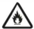
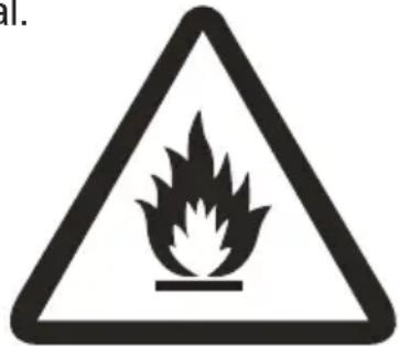
Appliance filled with flammable gas R32.
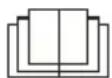
Before use the appliance, read the owner's manual first.

Before install the appliance, read the installation manual first.
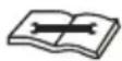
Before repair the appliance, read the service manual first.
The Refrigerant
OPERATION INSTRUCTIONS
- To realize the function of the air conditioner unit, a special refrigerant circulates in the system. The used refrigerant is the fluoride R32, which is specially cleaned. The refrigerant is flammable and inodorous. Furthermore, it can leads to explosion under certain conditions. But the flammability of the refrigerant is very low. It can be ignited only by fire.
- Compared to common refrigerants, R32 is a nonpolluting refrigerant with no harm to the ozonosphere. The influence upon the greenhouse effect is also lower. R32 has got very good thermodynamic features which lead to a really high energy efficiency. The units therefore need a less filling.
WARNING :
DO NOT use means to accelerate the defrosting process or to clean, other than those recommended by the manufacture. Should repair be necessary, contact your nearest authorized Service Center. Any repairs carried out by unqualified personnel may be dangerous. The appliance shall be stored in a room without continuously operating ignition sources. (for example: open flames, an operating gas appliance or an operating electric heater.) DO NOT pierce or burn.
Appliance shall be installed, operated and stored in a room with a floor area larger than X m² (Please refer to table "a" in section of "Safety Operation of Inflammable Refrigerant" for Space X.)
Appliance filled with flammable gas R32. For repairs, strictly follow manufacturer's instructions only. Be aware that refrigrants not contain odour. Read specialist's manual.

Precautions
OPERATION INSTRUCTIONS
WARNING
Operation and Maintenance
- This appliance can be used by children aged from 8 years and above and persons with reduced physical, sensory or mental capabilities or lack of experience and knowledge if they have been given supervision or instruction concerning use of the appliance in a safe way and understand the hazards involved.
•Children shall not play with the appliance. - Cleaning and user maintenance shall not be made by children without supervision.
- DO NOT connect air conditioner to multi-purpose socket. Otherwise, it may cause fire hazard.
- Disconnect power supply when cleaning air conditioner. Otherwise, it may cause electric shock.
- If the supply cord is damaged, it must be replaced by the manufacturer, its service agent or similarly qualified persons in order to avoid a hazard.
- DO NOT wash the air conditioner with water to avoid electric shock.
- DO NOT spray water on indoor unit. It may cause electric shock or malfunction.
•After removing the filter, do not touch fins to avoid injury. - DO NOT use fire or hair dryer to dry the filter to avoid deformation or fire hazard.
Precautions
OPERATION INSTRUCTIONS

WARNING
- Maintenance must be performed by qualified professionals. Otherwise, it may cause personal injury or damage.
- DO NOT repair air conditioner by yourself. It may cause electric shock or damage. Please contact your dealer when you need to repair air conditioner.
- DO NOT extend fingers or objects into air inlet or air outlet. It may cause personal injury or damage.
- DO NOT block air outlet or air inlet. It may cause malfunction.
- DO NOT spill water on the remote controller, otherwise the remote controller may be broken.
- When below phenomenon occurs, please turn off air conditioner and disconnect power immediately, and then contact the dealer or qualified professionals for service.
• Power cord is overheating or damaged. - There is abnormal sound during operation.
- Circuit break trips off frequently.
• Air conditioner gives off burning smell. - There is a leakage from the indoor unit.
- If the air conditioner operates under abnormal conditions, it may cause malfunction, electric shock or fire hazard.
- When turning on or turning off the unit by emergency operation switch, please press this switch with an insulating object other than metal.
- DO NOT step on top panel of outdoor unit, or put heavy objects. It may cause damage or personal injury.
Precautions
OPERATION INSTRUCTIONS
WARNING
Attachment
• Installation must be performed by qualified professionals. Otherwise, it may cause personal injury or damage.
- Must follow the electric safety regulations when installing the unit.
- According to the local safety regulations, use qualified power supply circuit and circuit break.
• Install the circuit break. If not, it may cause malfunction.
- An all-pole disconnection switch having a contact separation of at least 3 mm in all poles should be connected in fixed wiring.
- Including an circuit break with suitable capacity, please note the following table. Air switch should be included magnet buckle and heating buckle function, it can protect the circuit-short and overload.
• Air Conditioner should be properly grounded. Incorrect grounding may cause electric shock.
- DO NOT use unqualified power cord.
- Make sure the power supply matches with the requirement of air conditioner. Unstable power supply or incorrect wiring or malfunction. Please install proper power supply cables before using the air conditioner.
- Properly connect the live wire, neutral wire and grounding wire of power socket.
- Be sure to cut off the power supply before proceeding any work related to electricity and safety.
Precautions
OPERATION INSTRUCTIONS
WARNING
• DO NOT put through the power before finishing installation.
- If the supply cord is damaged, it must be replaced by the manufacturer, its service agent or similarly qualified persons in order to avoid a hazard.
- The temperature of refrigerant circuit will be high, please keep the interconnection cable away from the copper tube.
- The appliance shall be installed in accordance with national wiring regulations.
- Installation must be performed in accordance with the requirement of NEC and CEC by authorized personnel only.
- The air conditioner is the first class electric appliance. It must be properly grounding with specialized grounding device by a professional. Please make sure it is always grounded effectively, otherwise it may cause electric shock.
- The yellow-green wire in air conditioner is grounding wire, which cannot be used for other purposes.
- The grounding resistance should comply with national electric safety regulations.
- The appliance must be positioned so that the plug is accessible.
- All wires of indoor unit and outdoor unit should be connected by a professional.
- If the length of power connection wire is insufficient, please contact the supplier for a new one. Avoid extending the wire by yourself.
Precautions
OPERATION INSTRUCTIONS
WARNING
- For the air conditioner with plug, the plug should be reachable after finishing installation.
- For the air conditioner without plug, an circuit break must be installed in the line.
- If you need to relocate the air conditioner to another place, only the qualified person can perform the work. Otherwise, it may cause personal injury or damage.
- Select a location which is out of reach for children and far away from animals or plants. If it is unavoidable, please add the fence for safety purpose.
- The indoor unit should be installed close to the wall.

Partnamesandtheirfunctions
OPERATION INSTRUCTIONS
INDOOR UNIT

CAUTION
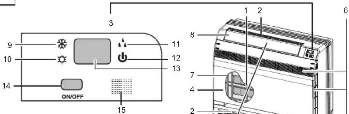
Before opening the front panel, be sure to stop the operation and turn the breaker OFF. DO NOT touch the metal parts on the inside of the indoor unit, as it may result in injury.
- Titanium Apatite Photocatalytic Air-Purifying Filter:
• These filters are attached to the inside of the air filters. - Air outlet
- Display
- Front panel
- Louvers (vertical blades)
• The louvers are inside of the air outlet. - Air inlet
- Air filter
- Flap (horizontal blade)
- Cool mode lamp
- Heat mode lamp
- Dry mode lamp
- Run lamp
- LED display
-
Indoor Unit ON/OFF switch:
-
Push this switch once to start operation.
Push once again to stop it.
• The operation mode refers to the following table.
| Model Mode | Temperature setting | Air flow rate | |
| COOLING ONLY | AUTO | 25°C | AUTO |
| HEAT PUMP | AUTO | 25°C | AUTO |
- This switch is useful when the remote controller is missing.
-
Signal receiver:
-
It receives signals from the remote controller.
- When the unit receives a signal, you will hear a short beep.
-
Settings changed.....beep.
-
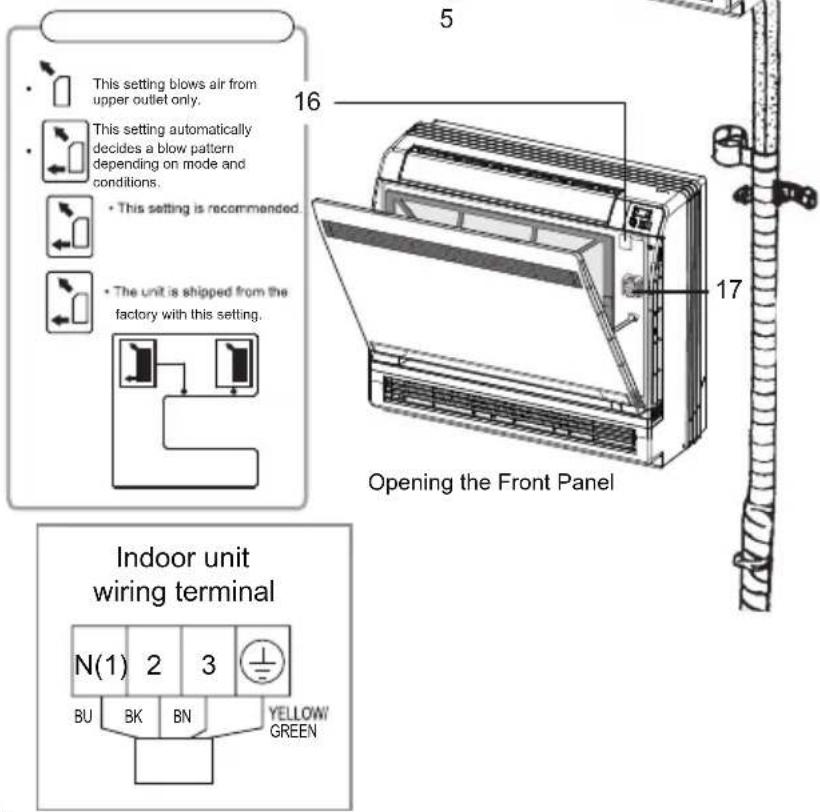
Air outlet selection switch
17.Room temperature sensor:
- It senses the air temperature around the unit.
2 How to use the remote control to operate the unit
OPERATION INSTRUCTIONS
Remote Controller Description
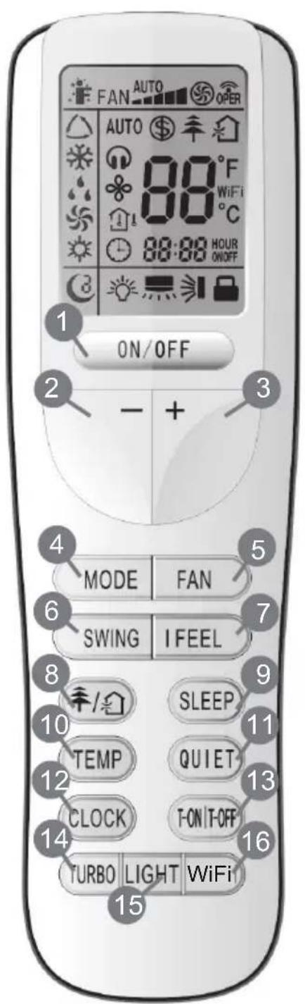
1 ON/OFF
Press it to start or stop operation.
2 - : Press it to decrease temperature setting.
3 + : Press it to increase temperature setting.
4 MODE
Press it to select operation mode (AUTO/COOL/DRY/FAN/HEAT).
5 FAN
Press it to set fan speed.
6 SWING
Press it set swing angle.
7 I FEEL
8
Press it to set HEALTH or AIR function.
9 SLEEP
10 TEMP
11 QUIET
Press it to set QUIET function.
12 CLOCK
Press it set clock.
13 T-ON|T-OFF
Press it to set auto-off /auto-on timer.
14 TURBO
15 LIGHT
Press it to turn on/off the light.
16 WiFi
How to use the remote control to operate the unit
OPERATION INSTRUCTIONS
Remote Controller Description
Note:
- This is a general use remote controller, it could be used for the air conditioners with multifunction; For some function, which the model does not have, if press the corresponding button on the remote controller that the unit will keep the original running status.
1 ON/OFF :
Press this button to turn on the unit .Press this button again to turn off the unit.
2 —:
Press this button to decrease set temperature. Holding it down above 2 seconds rapidly decreases set temperature. In AUTO mode, set temperature is not adjustable.
3 + :
Press this button to increase set temperature. Holding it down above 2 seconds rapidly increases set temperature. In AUTO mode, set temperature is not adjustable.
4 MODE :
Each time you press this button, a mode is selected in a sequence that goes from AUTO, COOL, DRY, FAN, and HEAT*, as the following:

flowchart
graph LR
    A["AUTO"] --> B["COOL"]
    B --> C["DRY"]
    C --> D["FAN HEAT"]
    D --> E["*"]
*Note: Only for models with heating function.
After energization, AUTO mode is defaulted. In AUTO mode, the set temperature will not be displayed on the LED of the indoor, and the unit will automatically select the suitable operation mode in accordance with the room temperature to make indoor room comfortable.
5 FAN:
This button is used for setting Fan Speed in the sequence that goes from AUTO, ▲, ▶, ▼, ▶, ▶ to ▶, then back to Auto.
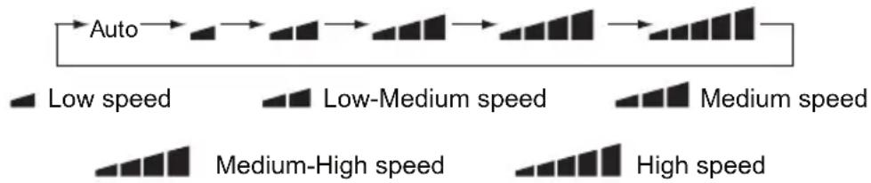
flowchart
graph LR
    A["Auto"] --> B["Low speed"]
    B --> C["Low-Medium speed"]
    C --> D["Medium speed"]
    D --> E["Medium-High speed"]
    E --> F["High speed"]
- X-FAN function: Hold fan speed button for 2 seconds in COOL or DRY mode, the icon “✿” is displayed and the indoor fan will continue operation for a few minutes in order to dry the indoor unit even though you have turned off the unit. After energization, X-FAN OFF is defaulted. X-FAN is not available in AUTO, FAN or HEAT mode.
This function indicates that moisture on evaporator of indoor unit will be blown after the unit is stopped to avoid mould.
- Having set X-FAN function on: After turning off the unit by pressing ON/OFF button indoor fan will continue running for a few minutes at low speed. In this period, Hold fan speed button for 2 seconds to stop indoor fan directly.
- Having set X-FAN function off: After turning off the unit by pressing ON/OFF button, the complete unit will be off directly.
Howtousetheremotecontroltooperatetheunit
OPERATION INSTRUCTIONS
6 SWING:
Press this button to set up and down swing angle, which circularly changes as below:
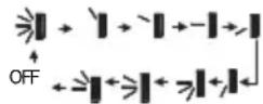
This remote controller is universal. If any command ≥slant , ≥slant or ≥slant is sent out, the unit will carry out the command as ≥slant
indicates the guide louver swings as:
7 I FEEL:
Press this button to turn on I FEEL function. The unit automatically adjust temperature according to the sensed temperature. Press this button again to cancel I FEEL function. When I FEEL function is turned on, the remote controller should be put within the area where indoor unit can receive the signal sent by the remote controller.
8
Press this button to achieve the on and off of healthy and scavenging functions in operation status. Press this button for the first time to start scavenging function;
LCD displays“💡”. Press the button for the second time to start healthy and scavenging functions simultaneously; LCD displays“💡” and “💡”. Press this button for the third time to quit healthy and scavenging functions simultaneously. Press the button for the fourth time to start healthy function; LCD display “💡”. Press this button again to repeat the operation above.
NOTE: This function is applicable to partial of models.
9 SLEEP:
- Press this button, can select Sleep 1 (1), Sleep 2 (2), Sleep 3 (3) and cancel the Sleep, circulate between these, after electrified, Sleep Cancel is defaulted.
- Sleep 1 is Sleep mode 1, in Cool mode: sleep status after run for one hour, the main unit setting temperature will increase 1 °C, setting temperature increased 2°C, the unit will run at this setting temperature; In Heat mode: sleep status after run for one hour, the setting temperature will decrease 1 °C, 2 hours, setting temperature will decrease 2 °C, then the unit will run at this setting temperature.
- Sleep 2 is sleep mode 2, that is air conditioner will run according to the presetting a group of sleep temperature curve.
- Sleep 3- the sleep curve setting under Sleep mode by DIY:
(1) Under Sleep 3 mode, press "Turbo" button for a long time, remote control enters into user individuation sleep setting status, at this time, the time of remote control will display "1 hour ", the setting temperature "88" will display the corresponding temperature of last setting sleep curve and blink (The first entering will display according to the initial curve setting value of original factory);
(2) Adjust "+" and "-" button, could change the corresponding setting temperature, after adjusted, press "Turbo" button for confirmation;
(3) At this time, 1 hour will be automatically increased at the timer position on the remote control, (that are "2 hours" or "3 hours" or "8 hours"), the place of setting temperature "88" will display the corresponding temperature of last setting sleep curve and blink;
(4) Repeat the above step (2) ∼ (3) operation, until 8 hours temperature setting finished, sleep curve setting finished, at this time, the remote control will resume the original timer display; temperature display will resume to original setting temperature.
Sleep 3- the sleep curve setting under SLEEP mode by DIY could be inquired:
- The user could accord to sleep curve setting method to inquire the presetting sleep curve, enter into user individuation sleep setting status, but do not change the temperature, press "Turbo" button directly for confirmation. Note: In the above presetting or enquiry procedure, if continuously within 10 seconds, there is no button pressed, the sleep curve setting within 10 seconds, there is no button pressed, the sleep curve setting status will be automatically quit and resume to display the original displaying. In the presetting or enquiry procedure, press "ON/OFF" button, "Mode" button, "Timer" button or "Sleep" button, the sleep curve setting or enquiry status will quit similarly.
How to use the remote control to operate the unit
OPERATION INSTRUCTIONS
10 TEMP:
Press this button, could select displaying the indoor setting temperature or indoor ambient temperature. When the indoor unit firstly power on it will display the setting temperature, if the temperature's displaying status is changed from other status to" ", displays the ambient temperature, 5 seconds later or within 5 seconds, it receives other remote control signal that will return to display the setting temperature. if the users have not set up the temperature displaying status, that will display the setting temperature.
11 QUIET:
Press this button, the Quiet status is under the Auto Quiet mode (display " 🔍" and "Auto" signal) and Quiet mode (display " 🔍" singal) and Quiet OFF (there is no signal of " 🔍" displayed), after powered on, the Quiet OFF is defaulted. Note: Under the Quiet mode (Display " 🔍" signal), the fan speed is not available.
12 CLOCK:
Press CLOCK button, blinking ⏻ . Within 5 seconds, pressing + or - button adjusts the present time. Holding down either button above 2 seconds increases or decreases the time by 1 minute every 0.5 second and then by 10 minutes every 0.5 second. During blinking after setting, press CLOCK button again to confirm the setting, and then ⏻ will be constantly displayed.
13 T-ON / T-OFF:
Press T-ON button to initiate the auto-ON timer. To cancel the auto-timer program, simply press this button again.
After press of this button, disappears and "ON "blinks 0000 is displayed for ON time setting. Within 5 seconds, press + or - butt on to adjust the time value. Every press of either button changes the time setting by 1 minute. Holding down either button rapidly changes the time setting by 1 minute and then 10 minutes. Within 5 seconds after setting, press TIMER ON button to confirm.
Press T-OFF button to initiate the auto-off timer. To cancel the auto-timer program, simply press the button again. TIMER OFF setting is the same as TIMER ON.
14 TURBO:
Press this button to activate / deactivate the Turbo function which enables the unit to reach the preset temperature in the shortest time. In COOL mode, the unit will blow strong cooling air at super high fan speed. In HEAT mode, the unit will blow strong heating air at super high fan speed.
15 LIGHT:
Press LIGHT button to turn on the display's light and press this button again to turn off the display's light. If the light is turned on, 🔊 is displayed. If the light is turned off, 🔊 disappears.
16 WiFi:
Press "WiFi" button to turn on or turn off WiFi function. When WiFi function is turned on, the "WiFi" icon will be displayed on remote controller; Under status of unit off, press "MODE" and "WiFi" buttons simultaneously for 1 second, WiFi module will restore to factory default setting.
- This function is only available for some models.
17 Combination of "+" and "-" buttons: About lock
Press "+ " and "-" buttons simultaneously to lock or unlock the keypad. If the remote controller is locked, 🔔 is displayed. In this case, pressing any button, 🔔 blinks three times.
How to use the remote control to operate the unit
OPERATION INSTRUCTIONS
18 Combination of "MODE" and "-" buttons: About switch between Fahrenheit and centigrade At unit OFF, press "MODE" and "-" buttons simultaneously to switch between °C and °F.
19 Combination of "TEMP" and "CLOCK" buttons : About Energy-saving Function Press "TEMP" and "CLOCK" simultaneously in COOL mode to start energy-saving function. Nixie tube on the remote controller displays "SE". Repeat the operation to quit the function.
20 Combination of "TEMP" and "CLOCK" buttons: About 8°C Heating Function Press "TEMP" and "CLOCK" simultaneously in HEAT mode to start 8°C Heating Function Nixie tube on the remote controller displays "\$" and a selected temperature of "8°C". (46°F if Fahrenheit is adopted). Repeat the operation to quit the function.
21 About Back-lighting Function
The unit lights for 4 seconds when energizing for the first time, and 3 seconds for later press.
Replacement of Batteries
- Remove the battery cover plate from the rear of the remote controller. (As shown in the figure.)
- Take out the old batteries.
- Insert two new AAA1.5V dry batteries, and pay attention to the polarity.
- Reinstall the battery cover plate.
★ Notes:
- When replacing the batteries, do not use old or different types of batteries, otherwise, it may cause malfunction.
- If the remote controller will not be used for a long time, please remove batteries to prevent batteries from leaking.
- The operation should be performed in its receiving range.
- It should be kept 1m away from the TV set or stereo sound sets.
- If the remote controller does not operate normally, please take the batteries out and reinsert them after 30 seconds. If it still cannot operate properly, replace the batteries.
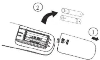
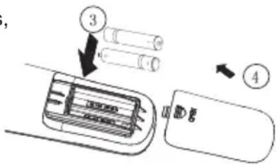
Sketch map for replacing batteries
3
Maintenance
OPERATION INSTRUCTIONS
Before inspection and maintenance of the unit. PLEASE set power switch to "OFF" to cut off the power supply.
3.1 Units
- Indoor unit, Outdoor unit and Remote controller
- Wipe them with dry soft cloth.
- Front panel
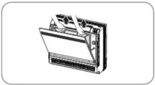
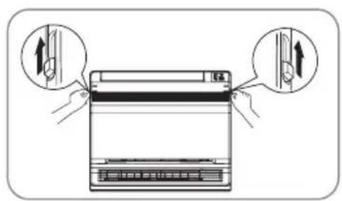
- Open the front panel.
Slide the two stoppers on the left and right sides inward until they click.
- Remove the front panel.
- Remove the string.
- Allowing the front panel to fall forward will enable you to remove it.
- Clean the front panel.
- Wipe it with a soft cloth soaked in water.
- Only neutral detergent may be used.
- In case of washing the front panel with water, dry it with cloth, dry it up in the shade after washing.
- Attach the front panel.
- Insert the front panel into the grooves of the unit (3 places).
- Attach the string to the right, inner-side of the front grille.
- Close the panel slowly.
CAUTION
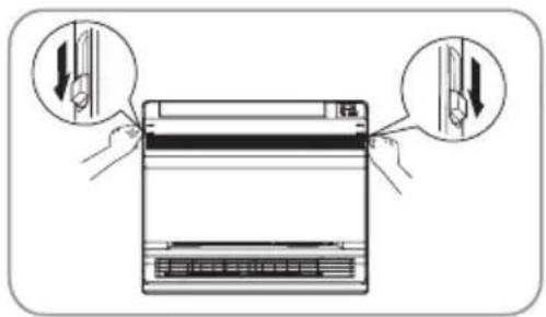
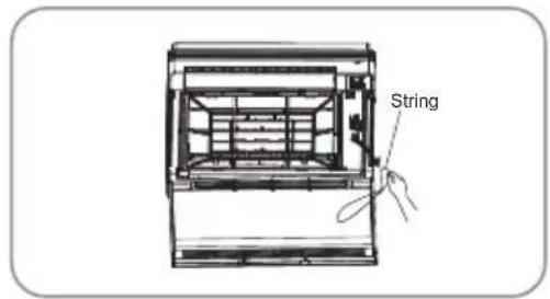
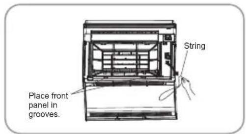
- DO NOT touch the metal parts of the indoor unit. If you touch those parts, this may cause an injury.
- When removing or attaching the front panel, use a robust and stable stool and watch your steps carefully.
- When removing or attaching the front panel, support the panel securely with hand to prevent it from falling.
- For cleaning, do not use hot water above 40^ , benzine, gasoline, thinner, nor other volatile oils, polishing compound, scrubbing brushes, nor other hand stuff.
• After cleaning, make sure that the front panel is securely fixed.
3.2 Filters
-
Open the front panel.
-
Remove the air filter.
- Press the claws on the right and left of the air filter down slightly, then pull upward.
- Take off the Titanium Apatite Photocatalytic Air-Purifying Filter.
- Hold the tabs of the frame, and remove the claws in 4 places.
natural_image
Diagram of a device with a lid and ventilation slots, showing internal components (no text or symbols)Maintenance
OPERATION INSTRUCTIONS
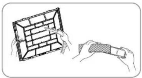
- Clean or replace each filter. See figure.
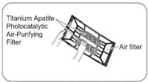
- Set the air filter and Titanium Apatite Photocatalytic Air-Purifying Filter as they were and close the front panel.
- Operation without air filters may result in troubles as dust will accumulate inside the indoor unit.
-
Wash the air filters with water or clean them with vacuum cleaner.
-
If the dust does not come off easily, wash them with neutral detergent thinned with lukewarm water, then dry them up in the shade.
- It is recommended to clean the air filters every week.
natural_image
Illustration of two hands holding a grid-patterned object, one being handled and the other holding a cylindrical object (no text or symbols)3.3 Titanium Apatite Photocatalytic Air-Purifying Filter
The Titanium Apatite Photocatalytic Air-Purifying Filter can be renewed by washing it with water once every 6 months. We recommend replacing it once every 3 years.
- Maintenance
- Vacuum dusts, and soak in warm water or water for about 10 to 15 minutes if dirt is heavy.
- Do not remove filter from frame when washing with water.
- After washing, shake off remaining water and dry in the shade.
- Since the material is made out of paper, do not wring out the filter when removing water from it.
- Replacement
Remove the tabs on the filter frame and replace with a new filter.
- Dispose of the old filter as flammable waste.
- Dispose of the old filter as flammable waste.
NOTE
- O peration with dirty filters:
(1) cannot deodorize the air. (2) cannot clean the air.
(3) results in poor heating or cooling. (4) may cause odour.
Main tenance
OPERATION INSTRUCTIONS
Check
| Check that the base, stand and other fittings of the outdoor unit are not decayed or corroded. |
| Check that nothing blocks the air inlets and the outlets of the indoor unit and the outdoor unit. |
| Check that the drain comes smoothly out of the drain hose during COOL or DRY operation.• If no drain water is seen, water may be leaking from the indoor unit. Stop operation and consult the service shop if this is the case. |
3.4 Before a long idle period
- Operate the "FAN only" for several hours on a fine day to dry out the inside.
- Press "MODE" button and select "FAN" operation.
- Press "ON/OFF" button and start operation.
- After operation stops, turn off the breaker for the room air conditioner.
- Clean the air filters and set them again.
- Take out batteries from the remote controller.
NOTE
- When a multi outdoor unit is connected, make sure the heating operation is not used at the other room before you use the fan operation.
| ※ Working temperature range | ||
| Indoor side DB/WB (°C) | Outdoor side DB/WB (°C) | |
| Maximum cooling | 32/23 | 43/26 |
| Maximum heating | 27/— | 24/18 |
The operating temperature range (outdoor temperature) for cooling unit is -15^ 43^ ; for cooling and heating unit is -22^ 43^ .
4
Operating guide
OPERATION INSTRUCTIONS
Working principle and special functions for cooling
Principle:
Air conditioner absorbs heat in the room and transmit to outdoor and discharged, so that indoor ambient temperature decreased, its cooling capacity will increase or decrease by outdoor ambient temperature.
Anti-freezing function:
If the unit is running in COOL mode and in low temperature, there will be frost formed on the heat exchanger, when indoor heat exchanger temperature decreased below 0°C the indoor unit microcomputer will stop compressor running and protect the unit.
Working principle and special functions for heating
Principle:
* Air conditioner absorbs heat from outdoor and transmits to indoor, in this way to increase room temperature. This is the heat pump heating principle, its heating capacity will be reduced due to outdoor temperature decrease.
* If outdoor temperature becomes very low, please operate with other heating equipments.
Defrosting:
* When outdoor temperature is low but high humidity, after a long while running, frost will form on outdoor unit, that will effect the heating effect, at this time, the auto defrosting function will act, the heat running will stop for 8 - 10 minutes.
* During the auto defrosting, the fan motors of indoor unit and outdoor unit will stop.
* During the defrosting, the indoor indicator flashes, the outdoor unit may emit vapor. This is due to the defrosting, it is not malfunction.
* After defrosting finished, the heating will recover automatically.
Anti-cool wind function:
In Heat mode, the following three kinds of status, if indoor heat exchanger has not achieve certain temperature that indoor fan motor will not start, in this way to prevent blowing cool wind (within 3 minutes):
- Heat operation just startedup. 2. After Auto defrosting operation is finished.
- Heating under low temperature.
The climate type of this unit is according to the nameplate.
Operating guide
OPERATION INSTRUCTIONS
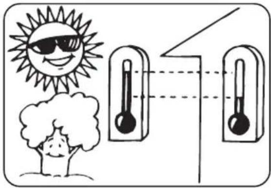
● The temperature should not be set lower than what you need. This would result to increase energy cost.
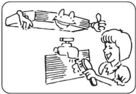
- Clean the air filter every week for higher efficiency.
natural_image
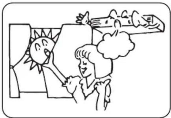
Illustration of a person writing at a desk with a magnifying glass and papers, while another person gestures with thumbs up (no text or symbols present)- Draw close curtains or close glass windows when cooling to prevent heat load from sun light which may cause more electricity cost.
natural_image
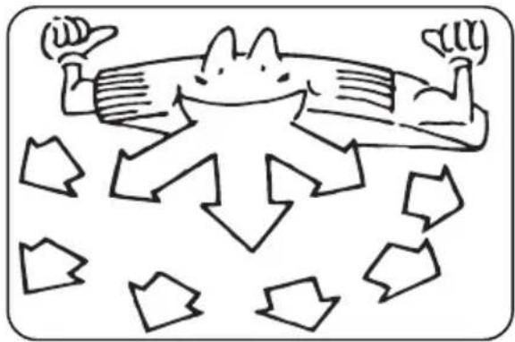
Cartoon illustration of a person reacting to a wall with a sun and a bird, no text or symbols present● To distribute cool air through out the roon, adjust air flow direction as shown by the arrows (see picture) to diffuse cool air.
natural_image
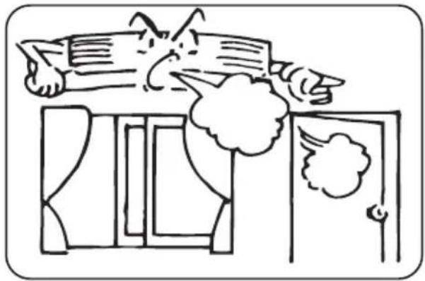
Cartoon illustration of a cat lying on the ground surrounded by downward-pointing arrows (no text or symbols)- Close window and door while operating the unit to prevent leakage of cooled air to save energy.
natural_image
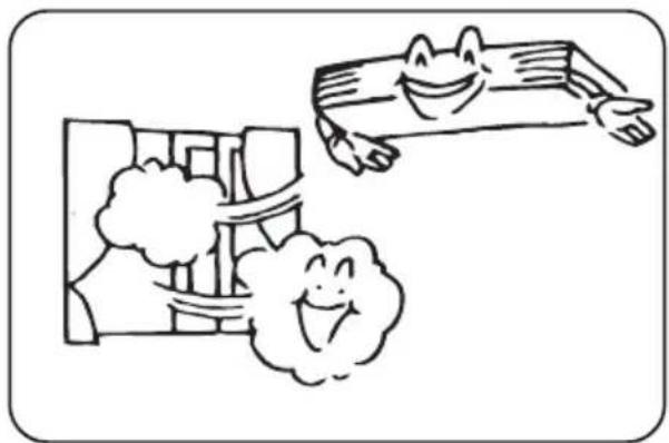
Simple line drawing of a person falling from above a window with smoke, no text or symbols present- In case of ineffective ventilation, open the window to ventilate the room air once in a while but not too long since cooled air will be uselessly drained out.
natural_image
Cartoon illustration of a smiling face pointing at a building with clouds (no text or symbols)5
Precautions
OPERATION INSTRUCTIONS
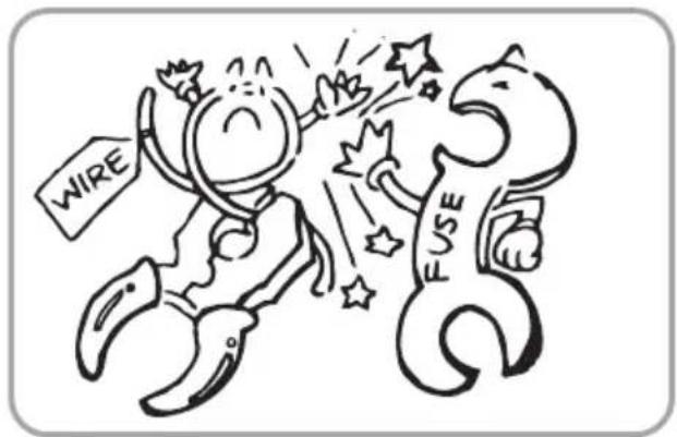
- Check electrical system (voltage and frequency). Use the proper power supply indicated on the unit to operate the airconditioner and only fuses with specified capacity. DO NOT use pieces of wire instead of fuse.
- DO NOT insert objects into the air inlet or outlet when the airconditioner is running as it may cause damage or personal injury. Also pay special attention when children are around.
natural_image
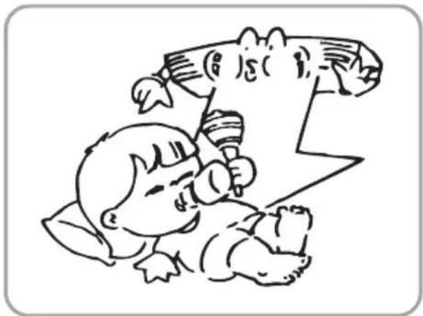
Simple line drawing of a cartoon character with wings and a mouth, no text or symbols present- DO NOT channel the air flow directly at people, especially infants, aged persons or patients.
natural_image
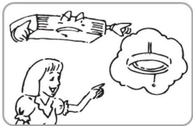
Cartoon illustration of a child lying on the floor with a cat on her back, holding a microphone (no text or symbols)- Turn off the airconditioner if, while running, electricity interference occurs. If the unit is not to be used for a long time, cut off the power supply main switch.
natural_image
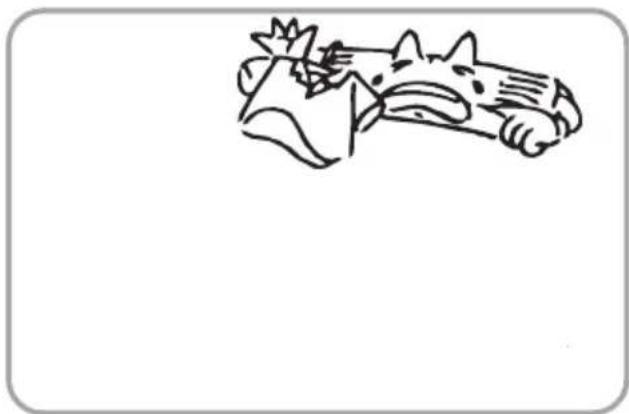
Illustration of a person pointing at a document with a thought bubble showing an eye (no text or symbols present)- DO NOT locate any obstacle against the air flow direction of indoor and outdoor unit. Inefficient performance or malfunction may result.
natural_image
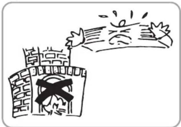
Simple line drawing of a cartoon animal head (no text or symbols)- DO NOT locate a heater or any other heat source close to the unit. The heat may deform plastic parts.
natural_image
Simple line drawing of a castle with a cross symbol and a broken tree, no text or symbols present.
Checking before contact the service man
OPERATION INSTRUCTIONS
Check the following before contact the service man. You may find the solution to your problems. After checking, if it still does not operate, please contact your local dealer.
| CAUSESPROBLEM | |
| NO operation | Check if electrical wire is damaged and check if breaker switch is still on.Check if the power supply is in order.Check if the timer switch is on or not. |
| The air conditioner runs but does not cool enough. | Check if the preset temperature is too high.Check if the sunlight shines directly into the room.Check if the door and window are opened.Check if there is anything obstructing the air discharge.Check if the exhaust fan still operates.Check if the air filter is dirty or clogged. |
| Vapor or mist fume coming out of the unit while running. | Hot air in the room mixes with cool air.This causes smoke fume. |
| Inoperative remote control. | Loosened or disconnected wire between the unit and the display.Check if the batteries are inserted in correct directions.Check if the batteries are exhausted or not. |
7
Installation of indoor unit
INSTALLATION INSTRUCTIONS
SELECTION OF INSTALLATION LOCATION.
- Such a place where cool air can be distributed throughout the room.
- Such a place where condensation water is easily drained out.
• Such a place that can handle the weight of indoor unit.
• Such a place which has easy access for maintenance.
• The appliance shall not be installed in the laundry.
THERE ARE 2 STYLES OF INSTALLATION.
- CEILING TYPE
- FLOOR TYPE
Each type is similar to the other as follows;
Indoor unit
The indoor unit should be sited in a place where:
1) the restrictions on installation specified in the indoor unit installation drawings are met.
2) both air intake and exhaust have clear paths met.
3) the unit is not in the path of direct sunlight.
4) the unit is away from the source of heat or steam.
5) there is no source of machine oil vapour (this may shorten indoor unit life).
6) cool (warm) air is circulated throughout the room.
7) the unit is away from electronic ignition type fluoroscent lamps (inverter or rapid stert type) as they may shorten the remote controller range.
8) the unit is at least 1 m away from any television or radio set (unit may cause interference with the picture or sound).
CAUTIONS FOR INSTALLATION WHERE
AIR CONDITIONER TROUBLEIS LIABLE
TOOCCUR.
• Where there is too much of oil area.
• Where it is acid base area.
• Where there is irregular electrical supply.
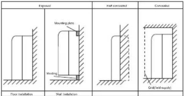
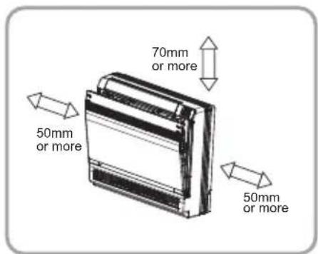
Indoor Unit Installation Drawings
The indoor unit may be mounted in any of the three styles shown here.
Console unit shall be installed on the ground or the position where is 0.3 m from the floor.
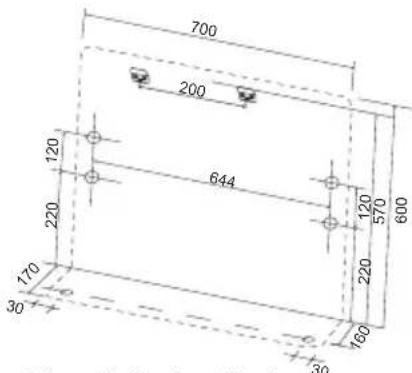
Location for securing the installation panel.
Schematic drawing of hooks:
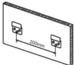
natural_image
Technical diagram of two identical electronic components mounted on a rectangular base, with a 200mm dimension label (no text or symbols beyond the measurement)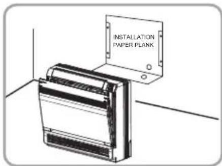
Installation of indoor unit
INSTALLATION INSTRUCTIONS
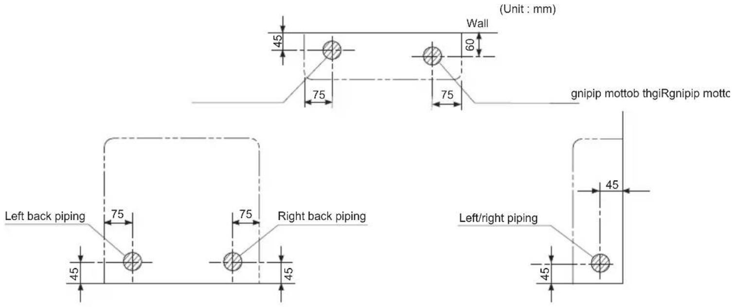
Refrigerant piping
1) Drill a hole (55mm in diameter) in the spot indicated by the symbol in the illustration as below.
2) The location of the hole is different depending on which side of the pipe is taken out.
3) For pipin, see Connecting the refrigerant pip, under Indoor Unit Installation(1).
4) Allow space around the pipe for a easier indoor unit pipe connection.

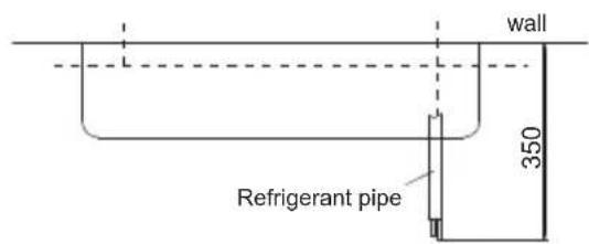
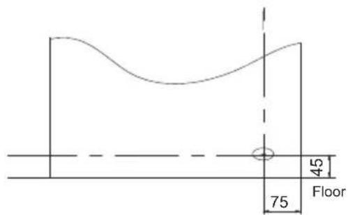
CAUTION
Min. allowable length
● The suggested shortest pipe length is 2.5 m, in order to avoid noise from the outdoor unit and vibration.
(Mechanical noise and vibration may occur depending on how the unit is installed and the environment in which it is used.)
● See the installation manual for the outdoor unit for the maximum pipe length.
- For multi-connections, see the installation manual for the multi-outdoor unit.
Installation of indoor unit
INSTALLATION INSTRUCTIONS
Boring a wall hole and installing wall embedded pipe
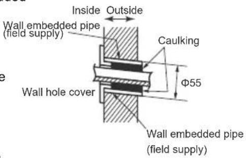
- For walls containing metal frame or metal board, be sure to use a wall embedded pipe and wall cover in the feed-through hole to prevent water leakage.
- Be sure to caulk the gaps around the pipes with caulking material to prevent water leakage.
1) Bore a feed-through hole of 55 mm in the wall so it has a down slope toward the outside.
2) Insert a wall pipe into the hole.
3) Insert a wall cover into wall pipe.
4) After completing refrigerant piping, wiring, and drain piping, caulk pipe hole gap with putty.
Drain piping
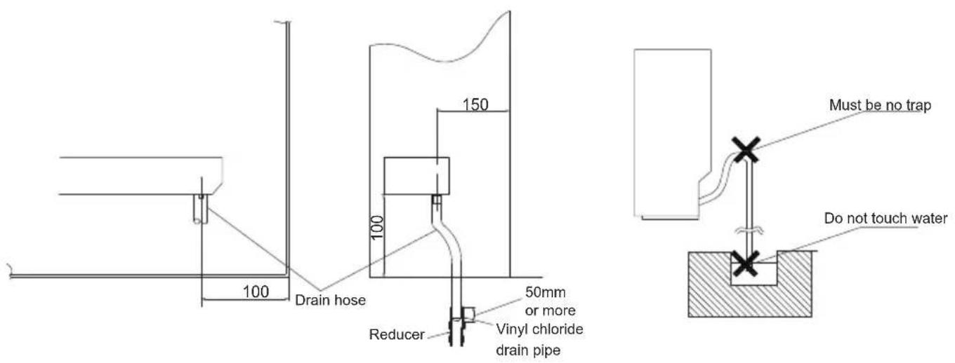
1) Use commercial regid polyvinyl chloride pipe (general VP 20 pipe, outer diameter 26 mm, inner diameter 20 mm) for the drain pipe.
2) The drain hose (outer diameter 18 mm at connecting end, 220 mm long) is supplied with the indoor unit. Prepare the drain pipe picture below position.
3) The drain pipe should be inclined downward so that water will flow smoothly without any accumulation. (Should not be trap.)
4) Insert the drain hose to this depth so it will not be pulled out of the drain pipe.
5) Insulate the indoor drain pipe with 10 mm or more of insulation material to prevent condensation.
6) Remove the air filters and pour some water into the drain pan to check the water flows smoothly.
Installation of indoor unit
INSTALLATION INSTRUCTIONS
Installing indoor unit
1.Preparation
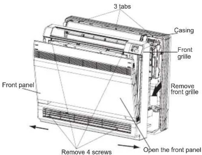
- Open the front panel, remove the 4 screws and dismount the front grille while pulling it forward.
- Follow the arrows to disengage the clasps on the front case to remove it.
- Follow the procedure below when removing the slit portions.
For Moldings
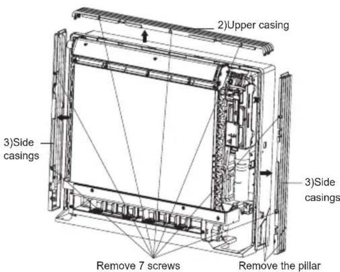
- Remove the pillars. (Remove the slit portions on the bottom frame using nippers.)
For Side Piping
- Remove the pillars.
1) Remove the 7 screws.
2) Remove the upper casing (2 tabs).
3) Remove the left and right casings (2 tabs on each side).
4) Remove the slit portions on the bottom frame and casings using nippers.
5) Return by following the steps in reverse order (3>2>1).
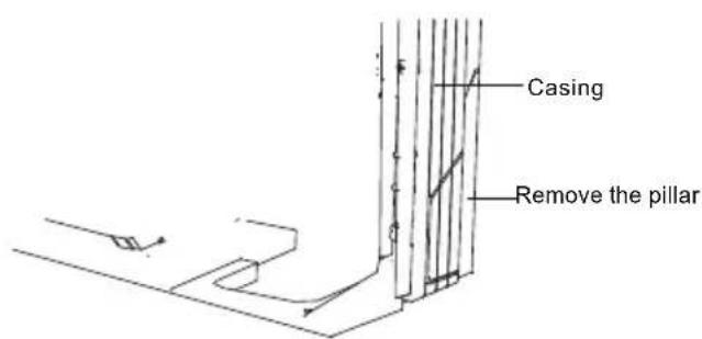
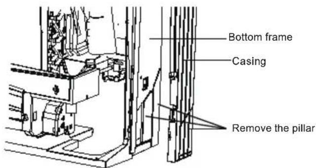
2. Installation
- Secure using 6 screws for floor installations. (Do not forget to secure to the rear wall.)
- For wall installations, secure the mounting plate using 5 screws and the indoor unit using 4 screws.
Installation of indoor unit
INSTALLATION INSTRUCTIONS
The mounting plate should be installed on a wall which can support the weight of the indoor unit.
1) Temporarily secure the mounting plate to the wall, make sure that the panel is completely level, and mark the boring points on the wall.
2) Secure the mounting plate to the wall with screws.
Floor Installation
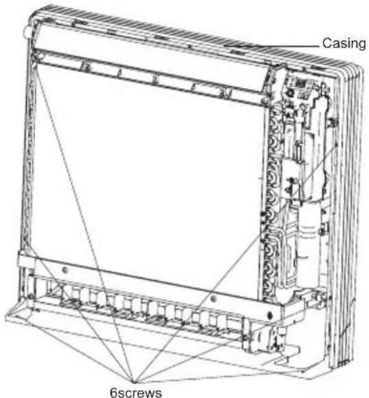
Wall Installation
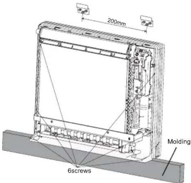
3) Once refrigerant piping and drain piping connections are complete, fill in the gap of the through hole with putty. A gap can lead to condensation on the refrigerant pipe, and drain pipe, and the entry of insects into the pipes.
4) Attach the front panel and front grille in their original positions once all connections are complete.
Flaring the pipe end
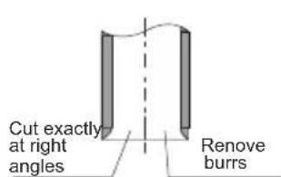
1) Cut the pipe end with a pipe cutter.
2) Remove burrs with the cut surface facing downward so that the chips do not enter the pipe.
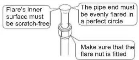
3) Fit the flare nut on the pipe.
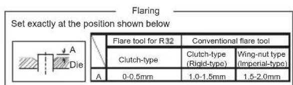
4)Flare the pipe.
5) Check that the flaring is properly made.
WARNING
1) DO NOT use mineral oil on flared part.
2) Prevent mineral oil from getting into the system as this would reduce the lifetime of the units.
3) NEVER use piping which had been used for previous installations. Only use parts which are delivered with the unit.
4) NEVER install a drier to this R32 unit in order to guarantee its lifetime.
5) The drying material may dissolve and damage the system.
6) Incomplete flaring may cause refrigerant gas leakage.
Installation of indoor unit
INSTALLATION INSTRUCTIONS
Connecting the refrigerant pipe
1) Use torque wrenches when tightening the flare nuts to prevent damage to the flare nuts and gas leaks.
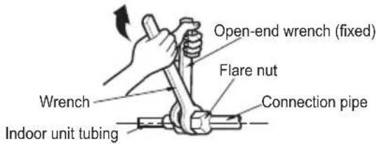
2) Align the centres of both flares and tighten the flares and tighten the flare nuts 3 or 4 turns by hand. Then tighten them fully with the torque wrenches.
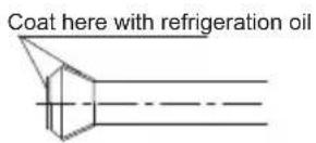
3) To prevent gas leakage, apply refrigeration oil on both inner and outer surfaces in the flare. (Use refrigeration oil for R32.)
| Flare nut tightening torque | ||
| Gas side | Liquid side | |
| 09K/12K | 18K | 09K/12K/18K |
| 3/8 inch | 1/2 inch | 1/4 inch |
| 31-35 N.m | 50-55 N.m | 15-20 N.m |
Caution on piping handling
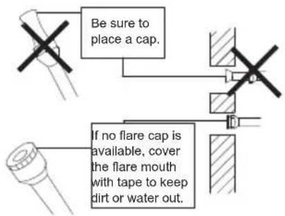
1) Protect the open end of the pipe against dust and moisture.
2) All pipe bends should be as gentle as possible. Use a pipe bender for bending.
(Bending radius should be 30 to 40 mm or larger.)
Selection of copper and heat insulation materials
- When using commercial copper pipes and fittings, observe the following:
1) Insulation material: Polyethylene foam Heat transfer rate: 0.041 to 0.052 W/mK (0.035 to 0.045 kcal/(mH ^C )
Refrigerant gas pipe's surface temperature reaches 110°C max.
Choose heat insulation materials that will withstand this temperature.
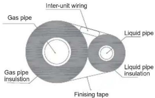
2) Be sure to insulate both the gas and liquid piping and to provide insulation dimensions as below.
| Gas side | Liquid side | Gas pipe thermal insulation | Liquid pipe thermal insulation | ||
| 09K/12K | 18K | 09K/12K | 18K | ||
| O.D. 9.5mm | O.D. 12.7mm | O.D. 6.4mm | I.D. 12-15mm | I.D. 14-16mm | I.D. 8-10mm |
| Thickness 0.8mm | Thickness 10mm Min. | ||||
3) Use separate thermal insulation pipes for gas and liquid refrigerant pipes.
Installation of indoor unit
INSTALLATION INSTRUCTIONS
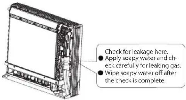
Checking for gas leakage
1) Check for leakage of gas after air purging
2) See the sections on air purges and gas leak checks in the installation manual for the outdoor unit.
Attaching the connection pipe
- Attach the pipe after checking for gas leakage, described above.
1) Cut the insulated portion of the on-site piping, matching it up with the connecting portion.
2) Secure the slit on the refrigerant piping side with the butt joint on the auxiliary piping using the tape, making sure there are no gaps.
3) Wrap the slit and butt joint with the included insulation sheet, making sure there are no gaps.
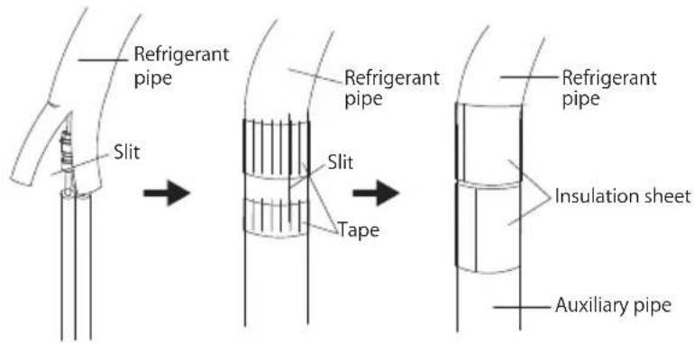

CAUTION
1) Insulate the joint of the pipes securely.
Incomplete insulation may lead to water leakage.
2) Push the pipe inside so it does not place undue force on the front grille.
Connecting the drain hose
Insert the supplied C drain hose into the socket of the drain pan.
Fully insert the drain hose until it adheres to a seat of the socket.
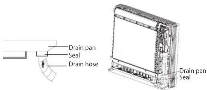
Installation of indoor unit
INSTALLATION INSTRUCTIONS
Wiring
With a Multi indoor unit, install as described in the installation manual supplied with the Multi outdoor unit.
● Live the sensor securing plate, remove the front metal plate cover, and connect the branch wiring to the terminal block.
1) Strip wire ends (15 mm)
2) Mach wire colours with terminal numbers on indoor and outdoor unit's terminal blocks and firmly screw wires to the corresponding terminals.
3) Connect the earth wires to the corresponding terminals.
4) Pull wires to make sure that they are securely latches up, then retain wires with wire retainer.
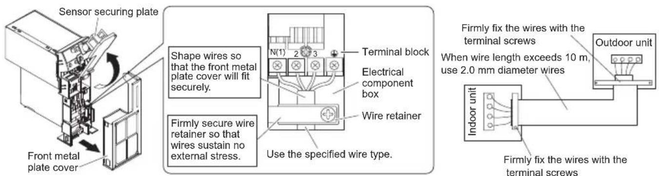

CAUTION
1) DO NOT use tapped wires, stranded wires, extensioncords or starburst connections, as they may cause overheating, electrical shock, or fire.
2) DO NOT use locally purchased electrical parts inside the product. (DO NOT branch the power for the drain pump, etc, from the terminal block. Doing so may cause electric shock or fire.)
8
Pipe preparation
INSTALLATION INSTRUCTIONS
8.1 PIPE AND ELECTRICAL WIRE CUTTING
- Use cutting tools easily found in the market.
● Measure precisely both outer and inner pipe. - Provide a little bit longer pipe than the measurement.
● Wire must be 1.5 m longer than the refrigerant tube.
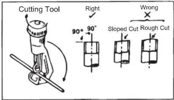
8.2 REAMING
- Clean inside of the inner refrigerant tube.
● While reaming, the tube end must be on the top of the reamer to prevent any dust going back into the tube.
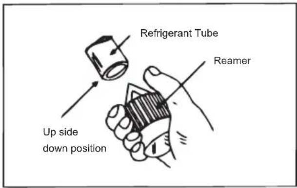
8.3 FLARING THE PIPE END
- Flare both ends of the pipe with flaring kit by fitting the flare nut on the pipe before flaring. Set the die on the pipe so that pipe end is 0.5 mm above top of the die. Check if the pipe end is even and perfectly round.
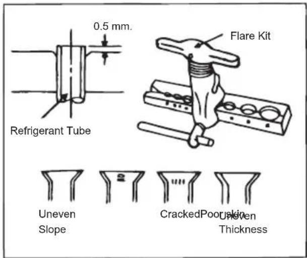
8.4 WIRE CONNECTION AND TAPE COVERING
(See the picture on the right side.)
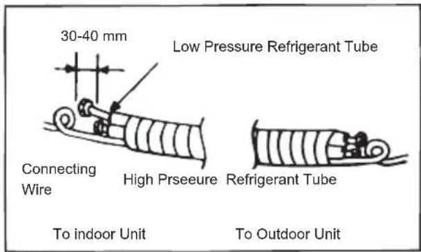

Refrigerant piping work
INSTALLATION INSTRUCTIONS
9.1 Select copper pipes for gas and liquid as informed in specific table (see the pipe table below)
9.2 For dust and moisture protection, before assembly of the pipe and its insulation, both end of the pipe must be covered.
9.3 Avoid pipe bending as much as possible. If it is necessary, the bending radius must be more than 3 cm or 4 cm.
Gas pipe and liquid pipe insulation depends upon copper pipe size and the insulation thickness = 3/8"
GAS PIPE TABLE
| MODEL | PIPE SIZE |
| 09K | 3/8" |
| 12K | 3/8" |
| 18K | 1/2" |
LIQUID PIPE TABLE
| MODEL | PIPE SIZE |
| 09K | 1/4" |
| 12K | 1/4" |
| 18K | 1/4" |
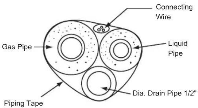
9.4 The connection between an indoor unit and an outdoor unit.
● Unscrew the flare nut for releasing pressure gas in the indoor unit. If there is no high pressure gas blowing out, it is the signal of a leaking indoor unit.
● Fit the flare nut to the liquid pipe. Flare the pipe's end with flare tool.
● Tighten both flare nuts into gas pipe and liquid pipe at the indoor unit with two holding spanners.
10 Routine check after installation
INSTALLATION INSTRUCTIONS
Check after installation
| Items to be checked | Possible malfunction Situation | |
| Has it been fixed firmly? | The unit may drop, shake or emit noise. | |
| Have you done the refrigerant leakage test? | It may cause insufficient refrigerating capacity. | |
| Is heat insulation sufficient? | It may cause condensation and dripping. | |
| Does the unit drain well? | It may cause condensation and dripping. | |
| Is the voltage in accordance with the rated voltage marked on the nameplate? | It may cause electric malfunction or damage the part. | |
| Is the electrical wiring and piping connection installed correctly and securely? | It may cause electric malfunction or damage the part. | |
| Has the unit been connected to a secure earth connection? | It may cause electrical leakage. | |
| Is the power cord specified? | It may cause electric malfunction or damage the part. | |
| Has the inlet and outlet been covered? | It may cause insufficient refrigerating capacity. | |
| Has the length of connection pipes and the refrigerant charge been record? | The refrigerating capacity is not accurate | |
| Is the inlet and outlet of piping hole been | It may cause insufficient cooling (heating).yticirtele retsaw ro yticapac?derevoc |
11 Configuration of connection pipe
INSTALLATION INSTRUCTIONS
- Standard length of connection pipe.
- 5 m, 7.5 m, 8 m.
- Min. length of connection pipe is 3 m.
3.Max. length of connection pipe.
Sheet 1 Max length of connection pipe Unit: m
| Cooling capacity | Max length of connection pipe |
| 5000Btu/h (1465W) | 15 |
| 7000Btu/h (2051W) | 15 |
| 9000Btu/h (2637W) | 15 |
| 12000Btu/h (3516W) | 20 |
| 18000Btu/h (5274W) | 25 |
| Cooling capacity | Max length of connection pipe |
| 24000Btu/h (7032W) | 25 |
| 28000Btu/h (8204W) | 30 |
| 36000Btu/h (10548W) | 30 |
| 42000Btu/h (12306W) | 30 |
| 48000Btu/h (14064W) | 30 |
- The additional refrigerant oil and refrigerant charging required after prolonging connection pipe.
- After the length of connection pipe is prolonged for 10 m at the basis of standard length, you should add 5 ml of refrigerant oil for each additional 5 m of connection pipe.
- The calculation method of additional refrigerant charging amount (on the basis of liquid pipe):
Additional refrigerant charging amount = prolonged length of liquid pipe × additional refrigerant charging amount per meter
- Basing on the length of standard pipe, add refrigerant according to the requirement as shown in the table. The additional refrigerant charging amount per meter is different according to the diameter of liquid pipe. See Sheet 2.
Configuration of connection pipe
INSTALLATION INSTRUCTIONS
Sheet 2. Additional refrigerant charging amount for R32
| Diameter of connection pipe mm | Indoor unit throttle | Outdoor unit throttle | ||
| Liquid pipe Gas pipe | Cooling only, cooling and heating (g / m) (g / m) | Cooling only (g / m) | cooling and heating | |
| Φ6 | Φ9.5 or Φ12 | 16 | 12 | 16 |
| Φ6 or Φ9.5 | Φ16 or Φ19 | 40 | 12 | 40 |
| Φ12 | Φ19 or Φ22.2 | 80 | 24 | 96 |
| Φ16 | Φ25.4 or Φ31.8 | 136 | 48 | 96 |
| Φ19 | - | 200 200 | 200 | |
| Φ22.2 | - | 280280 | 280 | |
Note: The additional refrigerant charging amount in Sheet 2 is recommended value, not compulsory.
12
Safety operation of flammable refrigerant
INSTALLATION INSTRUCTIONS
Qualification requirement for installation and maintenance man
- All the work men who are engaging in the refrigeration system should bear the valid certification awarded by the authoritative organization and the qualification for dealing with the refrigeration system recognized by this industry. If it needs other technician to maintain and repair the appliance, they should be supervised by the person who bears the qualification for using the flammable refrigerant.
- It can only be repaired by the method suggested by the equipment's manufacturer.
Installation notes
- The air conditioner is not allowed to use in a room that has running fire (such as fire source, working coal gas ware, operating heater).
- It is not allowed to drill hole or burn the connection pipe.
- The air conditioner must be installed in a room that is larger than the minimum room area. The minimum room area is shown on the nameplate or following table a.
- Leak test is a must after installation.
table a - Minimum room area ( m^2 )
| Minimum room area( m^2 ) | Charge amount (kg) | ≤1.2 | 3456.7 | 8122. | 212.3 | 2.4 | 2.5. | 1.9 | 2.1 | ||||||
| floor location | / | 14.5 | 8622 | 24.8 | 27.8 | 334.3 | 37.8 | 5145.4 | 453.6 | 41. | 49. | ||||
| window mounted | / | 5.2 | 6.1 | 7 | 7.9 | 8.9 | 10 | 11.2 | 12.4 | 13.6 | 15 | 16.3 | 17.8 | 19.3 | |
| wall mounted | / | 1.6 | 1.9 | 2.1 | 2.4 | 2.8 | 3.1 | 3.4 | 3.8 | 4.2 | 4.6 | 5 | 5.5 | 6 | |
| ceiling mounted | / | 1.1 | 1.3 | 1.4 | 1.6 | 1.8 | 2.1 | 2.3 | 2.6 | 2.8 | 3.1 | 3.4 | 3.7 | 4 |
Maintenance notes
- Check whether the maintenance area or the room area meet the requirement of the nameplate.
- It is only allowed to be operated in the rooms that meet the requirement of the nameplate.
- Check whether the maintenance area is well-ventilated.
- The continuous ventilation status should be kept during the operation process.
- Check whether there is fire source or potential fire source in the maintenance area.
- The naked flame is prohibited in the maintenance area; and the "no smoking" warning board should be hanged.
- Check whether the appliance mark is in good condition.
- Replace the vague or damaged warning mark.
Welding
- If you should cut or weld the refrigerant system pipes in the process of maintaining, please follow the steps as below:
Safety operation of flammable refrigerant
INSTALLATION INSTRUCTIONS
a. Shut down the unit and cut power supply
b. Eliminate the refrigerant
c. Vacuuming
d. Clean it with N2 gas
e. Cutting or welding
f. Carry back to the service spot for welding
- The refrigerant should be recycled into the specialized storage tank.
- Make sure that there is not any naked flame near the outlet of the vacuum pump and it is well-ventilated.
Filling the refrigerant
- Use the refrigerant filling appliances specialized for R32. Make sure that different kinds of refrigerant will not contaminate with each other.
- The refrigerant tank should be kept upright at the time of filling refrigerant.
- Stick the label on the system after filling is finished (or have not finished).
- Do not overfilling.
- After filling is finished, please do the leakage detection before test running; another time of leak detection should be done when it is removed.
Safety instructions for transportation and storage
- Please use the flammable gas detector to check before unload and open the container.
- No fire source and smoking.
- According to the local rules and laws.
Content
Operation Notices
The Refrigerant....40
Precautions....41-45
Parts Name....46
Installation Notice
Safety operation of flammable refrigerant.... 47-48
Installation dimension diagram 49
Safety precautions for installing and relocating the unit.... 50
Tools for installation 51
Selection of installation location 51
Requirements for electric connection 52
Installation
Installation of outdoor unit 53-55
Vacuum pumping 56
Leakage detection ....56
Check after installation 57
Test and operation
Test operation ....57
Attachment
Configuration of connection pipe....58-59
Pipe expanding method ....60
This appliance is not intended for use by persons (including children) with reduced physical, sensory or mental capabilities, or lack of experience and knowledge, unless they have been given supervision or instruction concerning use of the appliance by a person responsible for their safety.
Children should be supervised to ensure that they do not play with the appliance.
If it needs to install, move or maintain the air conditioner, please contact dealer or local service center to conduct it at first. Air conditioner must be installed, moved or maintained by appointed unit. Otherwise, it may cause serious damage or personal injury or death.
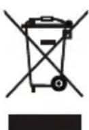
This marking indicates that this product should not be disposed with other household wastes throughout the EU. To prevent possible harm to the environment or human health from uncontrolled waste disposal, recycle it responsibly to promote the sustainable reuse of material resources. To return your used device, please use the return and collection systems or contact the retailer where the product was purchased. They can take this product for environmental safe recycling.
R32: 675
Explanation of Symbols

DANGER
Indicates a hazardous situation that, if not avoided, will result in death or serious injury.

WARNING
Indicates a hazardous situation that, if not avoided, could result in death or serious injury.

CAUTION
Indicates a hazardous situation that, if not avoided, may result in minor or moderate injury.

NOTICE
Indicates important but not hazard-related information, used to indicate risk of property damage.

Indicates a hazard that would be assigned a signal word WARNING or CAUTION.
Exception Clauses
Manufacturer will bear no responsibilities when personal injury or property loss is caused by the following reasons.
- Damage the product due to improper use or misuse of the product;
- Alter, change, maintain or use the product with other equipment without abiding by the instruction manual of manufacturer;
- After verification, the defect of product is directly caused by corrosive gas;
- After verification, defects are due to improper operation during transportation of product;
- Operate, repair, maintain the unit without abiding by instruction manual or related regulations;
- After verification, the problem or dispute is caused by the quality specification or performance of parts and components that produced by other manufacturers;
- The damage is caused by natural calamities, bad using environment or force majeure.
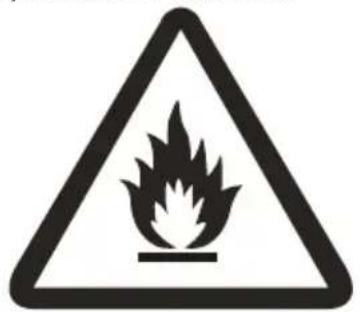
Please read this operating manual carefully before operating the unit.

Appliance filled with flammable gas R32.

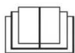
Before use the appliance, read the owner's manual first.

Before install the appliance, read the installation manual first.

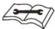
Before repair the appliance, read the service manual first.
The figures in this manual may be different with the material objects, please refer to the material objects for reference.
The Refrigerant
- To realize the function of the air conditioner unit, a special refrigerant circulates in the system. The used refrigerant is the fluoride R32, which is specially cleaned. The refrigerant is flammable and inodorous. Furthermore, it can leads to explosion under certain conditions. But the flammability of the refrigerant is very low. It can be ignited only by fire.
- Compared to common refrigerants, R32 is a nonpolluting refrigerant with no harm to the ozonosphere. The influence upon the greenhouse effect is also lower. R32 has got very good thermodynamic features which lead to a really high energy efficiency. The units therefore need a less filling.
WARNING:
DO NOT use means to accelerate the defrosting process or to clean, other than those recommended by the manufacture. Should repair be necessary, contact your nearest authorized Service Center.
Any repairs carried out by unqualified personnel may be dangerous.
The appliance shall be stored in a room without continuously operating ignition sources. (for example: open flames, an operating gas appliance or an operating electric heater.)
DO NOT pierce or burn.
Appliance shall be installed, operated and stored in a room with a floor area larger than "X"m2. (Please refer to table "a" in section of "Safety Operation of Inflammable Refrigerant" for Space X.)
Appliance filled with flammable gas R32. For repairs, strictly follow manufacturer's instructions only.
Be aware that refrigrants not contain odour.
Read specialist's manual.

Precautions
WARNING
Operation and Maintenance
- This appliance can be used by children aged from 8 years and above and persons with reduced physical, sensory or mental capabilities or lack of experience and knowledge if they have been given supervision or instruction concerning use of the appliance in a safe way and understand the hazards involved.
•Children shall not play with the appliance. - Cleaning and user maintenance shall not be made by children without supervision.
- DO NOT connect air conditioner to multi-purpose socket. Otherwise, it may cause fire hazard.
- Disconnect power supply when cleaning air conditioner. Otherwise, it may cause electric shock.
- If the supply cord is damaged, it must be replaced by the manufacturer, its service agent or similarly qualified persons in order to avoid a hazard.
- DO NOT wash the air conditioner with water to avoid electric shock.
- DO NOT spray water on indoor unit. It may cause electric shock or malfunction.
•After removing the filter, do not touch fins to avoid injury. - DO NOT use fire or hair dryer to dry the filter to avoid deformation or fire hazard.
Precautions
WARNING
- Maintenance must be performed by qualified professionals. Otherwise, it may cause personal injury or damage.
- DO NOT repair air conditioner by yourself. It may cause electric shock or damage. Please contact your dealer when you need to repair air conditioner.
- DO NOT extend fingers or objects into air inlet or air outlet. It may cause personal injury or damage.
- DO NOT block air outlet or air inlet. It may cause malfunction.
- DO NOT spill water on the remote controller, otherwise the remote controller may be broken.
- When below phenomenon occurs, please turn off air conditioner and disconnect power immediately, and then contact the dealer or qualified professionals for service.
• Power cord is overheating or damaged. - There is abnormal sound during operation.
- Circuit break trips off frequently.
• Air conditioner gives off burning smell.
• There is a leakage from the indoor unit. - If the air conditioner operates under abnormal conditions, it may cause malfunction, electric shock or fire hazard.
- When turning on or turning off the unit by emergency operation switch, please press this switch with an insulating object other than metal.
- DO NOT step on top panel of outdoor unit, or put heavy objects. It may cause damage or personal injury.
Precautions
WARNING
Attachment
- Installation must be performed by qualified professionals. Otherwise, it may cause personal injury or damage.
- Must follow the electric safety regulations when installing the unit.
- According to the local safety regulations, use qualified power supply circuit and circuit break.
• Install the circuit break. If not, it may cause malfunction. - An all-pole disconnection switch having a contact separation of at least 3 mm in all poles should be connected in fixed wiring.
- Including an circuit break with suitable capacity, please note the following table. Air switch should be included magnet buckle and heating buckle function, it can protect the circuit-short and overload.
• Air Conditioner should be properly grounded. Incorrect grounding may cause electric shock. - DO NOT use unqualified power cord.
- Make sure the power supply matches with the requirement of air conditioner. Unstable power supply or incorrect wiring may result in electric shock, fire hazard or malfunction. Please install proper power supply cables before using the air conditioner.
- Properly connect the live wire, neutral wire and grounding wire of power socket.
Precautions
WARNING
- Be sure to cut off the power supply before proceeding any work related to electricity and safety.
- DO NOT put through the power before finishing installation.
- If the supply cord is damaged, it must be replaced by the manufacturer, its service agent or similarly qualified persons in order to avoid a hazard.
- The temperature of refrigerant circuit will be high, please keep the interconnection cable away from the copper tube.
- The appliance shall be installed in accordance with national wiring regulations.
- Installation must be performed in accordance with the requirement of NEC and CEC by authorized personnel only.
- The air conditioner is the first class electric appliance. It must be properly grounding with specialized grounding device by a professional. Please make sure it is always grounded effectively, otherwise it may cause electric shock.
- The yellow-green wire in air conditioner is grounding wire, which cannot be used for other purposes.
- The grounding resistance should comply with national electric safety regulations.
- The appliance must be positioned so that the plug is accessible.
- All wires of indoor unit and outdoor unit should be connected by a professional.
Precautions

WARNING
- If the length of power connection wire is insufficient, please contact the supplier for a new one. Avoid extending the wire by yourself.
- For the air conditioner with plug, the plug should be reachable after finishing installation.
- For the air conditioner without plug, an circuit break must be installed in the line.
- If you need to relocate the air conditioner to another place, only the qualified person can perform the work. Otherwise, it may cause personal injury or damage.
- Select a location which is out of reach for children and far away from animals or plants. If it is unavoidable, please add the fence for safety purpose.
- The indoor unit should be installed close to the wall.
- Instructions for installation and use of this product are provided by the manufacturer.
Working temperature range
| Indoor side DB/WB (°C) | Outdoor side DB/WB ( ) °C | |
| 62/3432/23gniloo | ||
| 81/42-/72grtiaeh m |
NOTICE:
- The operating temperature range (outdoor temperature) for cooling only unit is -15^ 43^ ; for heat pump unit is -22^ 43^ .
Parts name
Outdoor Unit
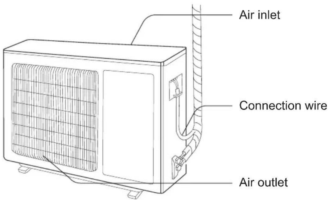
NOTICE:
Actual product may be different from above graphics, please refer to actual products.
Safety operation of flammable refrigerant
Qualification requirement for installation and maintenance man
- All the work men who are engaging in the refrigeration system should bear the valid certification awarded by the authoritative organization and the qualification for dealing with the refrigeration system recognized by this industry. If it needs other technician to maintain and repair the appliance, they should be supervised by the person who bears the qualification for using the flammable refrigerant.
- It can only be repaired by the method suggested by the equipment's manufacturer.
Installation notes
- The air conditioner is not allowed to use in a room that has running fire (such as fire source, working coal gas ware, operating heater).
- It is not allowed to drill hole or burn the connection pipe.
- The air conditioner must be installed in a room that is larger than the minimum room area. The minimum room area is shown on the nameplate or following table a.
- Leak test is a must after installation.
table a- Minimum room area ( m^2 )
| Minimum room area( m^2 ) | Charge amount (kg) | ≤1.2 | 1.3 | 1.4 | 1.5 | 1.6 | 1.7 | 1.8 | 1.9 | 2 | 2.1 | 2.2 | 2.3 | 2.4 | 2.5 |
| floor location | / | 14.5 | 16.8 | 19.3 | 22 | 24.8 | 27.8 | 31 | 34.3 | 37.8 | 41.5 | 45.4 | 49.4 | 53.6 | |
| window mounted | / | 5.2 | 6.1 | 7 | 7.9 | 8.9 | 10 | 11.2 | 12.4 | 13.6 | 15 | 16.3 | 17.8 | 19.3 | |
| wall mounted | / | 1.6 | 1.9 | 2.1 | 2.4 | 2.8 | 3.1 | 3.4 | 3.8 | 4.2 | 4.6 | 5 | 5.5 | 6 | |
| ceiling mounted | / | 1.1 | 1.3 | 1.4 | 1.6 | 1.8 | 2.1 | 2.3 | 2.6 | 2.8 | 3.1 | 3.4 | 3.7 | 4 |
Maintenance notes
- Check whether the maintenance area or the room area meet the requirement of the nameplate.
- It is only allowed to be operated in the rooms that meet the requirement of the nameplate.
- Check whether the maintenance area is well-ventilated.
- The continuous ventilation status should be kept during the operation process.
- Check whether there is fire source or potential fire source in the maintenance area.
- The naked flame is prohibited in the maintenance area; and the “no smoking” warning board should be hanged.
- Check whether the appliance mark is in good condition.
- Replace the vague or damaged warning mark.
Welding
- If you should cut or weld the refrigerant system pipes in the process of maintaining, please follow the steps as below:
Safety operation of flammable refrigerant
a. Shut down the unit and cut power supply
b. Eliminate the refrigerant
c. Vacuuming
d. Clean it with N2 gas
e. Cutting or welding
f. Carry back to the service spot for welding
- The refrigerant should be recycled into the specialized storage tank.
- Make sure that there is not any naked flame near the outlet of the vacuum pump and it is well-ventilated.
Filling the refrigerant
- Use the refrigerant filling appliances specialized for R32. Make sure that different kinds of refrigerant will not contaminate with each other.
- The refrigerant tank should be kept upright at the time of filling refrigerant.
- Stick the label on the system after filling is finished (or have not finished).
- Do not overfilling.
- After filling is finished, please do the leakage detection before test running; another time of leak detection should be done when it is removed.
Safety instructions for transportation and storage
- Please use the flammable gas detector to check before unload and open the container.
- No fire source and smoking.
- According to the local rules and laws.
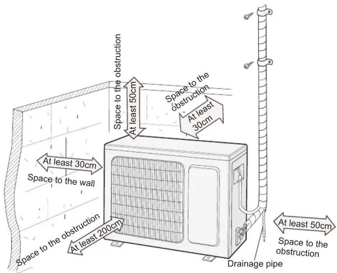
Installation dimension diagram
Safety precautions for installing and relocating the unit
To ensure safety, please be mindful of the following precautions.
Warning
- When installing or relocating the unit, be sure to keep the refrigerant circuit free from air or substances other than the specified refrigerant.
Any presence of air or other foreign substance in the refrigerant circuit will cause system pressure rise or compressor rupture, resulting in injury.
- When installing or moving this unit, do not charge the refrigerant which is not comply with that on the nameplate or unqualified refrigerant.
Otherwise, it may cause abnormal operation, wrong action, mechanical malfunction or even series safety accident.
- When refrigerant needs to be recovered during relocating or repairing the unit, be sure that the unit is running in cooling mode. Then, fully close the valve at high pressure side (liquid valve). About 30 - 40 seconds later, fully close the valve at low pressure side (gas valve), immediately stop the unit and disconnect power. Please note that the time for refrigerant recovery should not exceed 1 minute.
If refrigerant recovery takes too much time, air may be sucked in and cause pressure rise or compressor rupture, resulting in injury.
- During refrigerant recovery, make sure that liquid valve and gas valve are fully closed and power is disconnected before detaching the connection pipe. If compressor starts running when stop valve is open and connection pipe is not yet connected, air will be sucked in and cause pressure rise or compressor rupture, resulting in injury.
- When installing the unit, make sure that connection pipe is securely connected before the compressor starts running.
If compressor starts running when stop valve is open and connection pipe is not yet connected, air will be sucked in and cause pressure rise or compressor rupture, resulting in injury.
- Prohibit installing the unit at the place where there may be leaked corrosive gas or flammable gas.
If there leaked gas around the unit, it may cause explosion and other accidents.
- Do not use extension cords for electrical connections. If the electric wire is not long enough, please contact a local service center authorized and ask for a proper electric wire.
Poor connections may lead to electric shock or fire.
- Use the specified types of wires for electrical connections between the indoor and outdoor units. Firmly clamp the wires so that their terminals receive no external stresses.
Electric wires with insufficient capacity, wrong wire connections and insecure wire terminals may cause electric shock or fire.
Tools for installation
| 1 Level meter 2 Screw driver 3 Impact drill | ||
| 4 Drill head 5 Pipe expander 6 Torque wrench | ||
| 7 Open-end wrench 8 Pipe cutter 9 Leakage detector | ||
| 10 Vacuum pump 11 Pressure meter 12 Universal meter | ||
| 13 Inner hexagon spanner 14 Measuring tape | ||
Note:
- Please contact the local agent for installation.
- Do not use unqualified power cord.
Selection of installation location
Basic requirement
Installing the unit in the following places may cause malfunction. If it is unavoidable, please consult the local dealer:
- The place with strong heat sources, vapors, flammableor explosive gas, or volatile objects spread in the air.
- The place with high-frequency devices (such as welding machine, medical equipment).
- The place near coast area.
- The place with oil or fumes in the air.
- The place with sulfureted gas.
- Other places with special circumstances.
- The appliance shall not be installed in the laundry.
- It is not allowed to be installed on the unstable or motive base structure (such as truck) or in the corrosive environment (such as chemical factory).
Outdoor unit
- Select a location where the noise and outflow air emitted by the outdoor unit will not affect neighborhood.
- The location should be well ventilated and dry, in which the outdoor unit will not be exposed directly to sunlight or strong wind.
- The location should be able to withstand the weight of outdoor unit.
- Make sure that the installation follows the requirement of installation dimension diagram.
- Select a location which is out of reach for children and far away from animals or plants. If it is unavoidable, please add the fence for safety purpose.
Requirements for electric connection
Safety precaution
- Must follow the electric safety regulations when installing the unit.
- According to the local safety regulations, use qualified power supply circuit and air switch.
-
Make sure the power supply matches with the requirement of air conditioner. Unstable power supply or incorrect wiring or malfunction. Please install proper power supply cables before using the air conditioner.
-
Properly connect the live wire, neutral wire and grounding wire of power socket.
-
Be sure to cut off the power supply before proceeding any work related to electricity and safety. For models with a power plug, make sure the plug is within reach after installation.
-
Do not put through the power before finishing installation.
-
If the supply cord is damaged, it must be replaced by the manufacturer, its service agent or similarly qualified persons in order to avoid a hazard.
-
The temperature of refrigerant circuit will be high, please keep the interconnection cable away from the copper tube.
-
The appliance shall be installed in accordance with national wiring regulations.
-
Appliance shall be installed, operated and stored in a room with a floor area larger than "X"m ^2 (see table 1).
Please notice that the unit is filled with flammable gas R32. Inappropriate treatment of the unit involves the risk of severe damages of people and material. Details to this refrigerant are found in chapter "refrigerant".
Grounding requirement
- The air conditioner is the first class electric appliance. It must be properly grounding with specialized grounding device by a professional. Please make sure it is always grounded effectively, otherwise it may cause electric shock.
- The yellow-green wire in air conditioner is grounding wire, which cannot be used for other purposes.
- The grounding resistance should comply with national electric safety regulations.
- The appliance must be positioned so that the plug is accessible.
- An all-pole disconnection switch having a contact separation of at least 3 mm in all poles should be connected in fixed wiring.
- Including an air switch with suitable capacity, please note the following table. Air switch should be included magnet buckle and heating buckle function, it can protect the circuit-short and overload. (Caution: please do not use the fuse only for protect the circuit)
| Air-conditioner | Air switch capacity |
| CON28OUECR32 | 10A |
| CON36OUECR32 | 16A |
| CON56OUECR32 | 16A |
Installation of outdoor unit
Step one: fix the support of outdoor unit (select it according to the actual installation situation)
- Select installation location according to the house structure.
- Fix the support of outdoor unit on the selected location with expansion screws.
Note:
• Take sufficient protective measures when installing the outdoor unit.
- Make sure the support can withstand at least four times of the unit weight.
- The outdoor unit should be installed at least 3 cm above the floor in order to install drain joint.
- For the unit with cooling capacity of 2300W \~5000W, 6 expansion screws are needed; for the unit with cooling capacity of 6000W \~8000W, 8 expansion screws are needed; for the unit with cooling capacity of 10000W \~16000W, 10 expansion screws are needed.
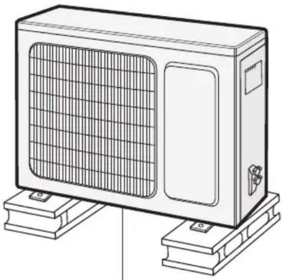
natural_image
Line drawing of a portable air conditioner unit mounted on a base (no text or symbols)at least 3 cm above the floor
Step two: install drain joint (Only for cooling and heating unit)
- Connect the outdoor drain joint into the hole on the chassis, as shown in the picture below.
- Connect the drain hose into the drain vent.
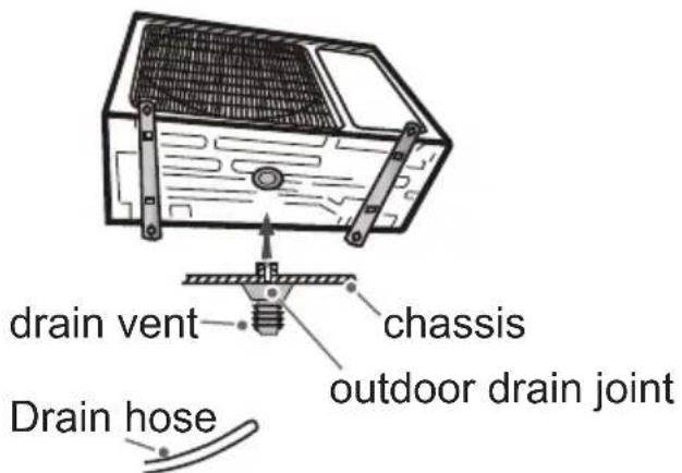
Step three: fix outdoor unit
- Place the outdoor unit on the support.
- Fix the foot holes of outdoor unit with bolts.
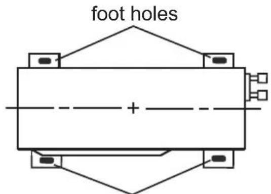
foot holes
Installation of outdoor unit
Step four: connect indoor and outdoor pipes
- Remove the screw on the right handle of outdoor unit and then remove the handle.
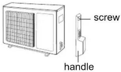
- Remove the screw cap of valve and aim the pipe joint at the bellmouth of pipe.
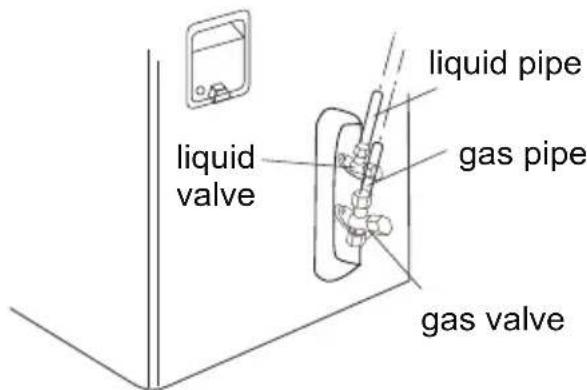
- Pretightening the union nut with hand.
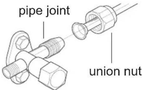
- Tighten the union nut with torque wrench by referring to the sheet below.
| Hex nut diameter | Tightening torque (N·m) |
| Φ 6 | 15~20 |
| Φ 9.52 | 30~40 |
| Φ 12 | 45~55 |
| Φ 16 | 60~65 |
| Φ 19 | 70~75 |
Step five: connect outdoor electric wire
- Remove the wire clip; connect the power connection wire and signal control wire (only for cooling and heating unit) to the wiring terminal according to the color; fix them with screws.
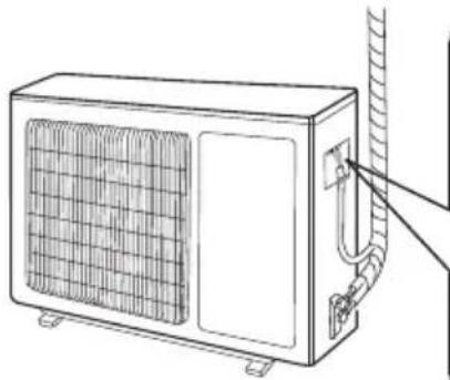
natural_image
Line drawing of a rectangular air conditioner unit with ventilation grille and attached piping (no text or symbols)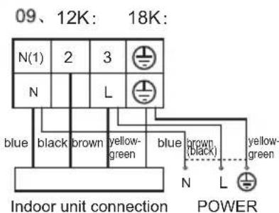
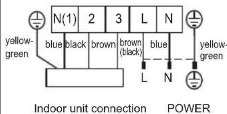
Note: the wiring board is for reference only, please refer to the actual one.
Installation of outdoor unit
- Fix the power connection wire and signal control wire with wire clip (only for cooling and heating unit).
Note:
- After tighten the screw, pull the power cord slightly to check if it is firm.
- Never cut the power connection wire to prolong or shorten the distance.
Step six: neaten the pipes
- The pipes should be placed along the wall, bent reasonably and hidden possibly. Min. semidiameter of bending the pipe is 10 cm.
- If the outdoor unit is higher than the wall hole, you must set a U-shaped curve in the pipe before pipe goes into the room, in order to prevent rain from getting into the room.
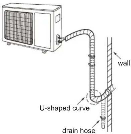
Vacuum pumping
Use vacuum pump
- Remove the valve caps on the liquid valve and gas valve and the nut of refrigerant charging vent.
- Connect the charging hose of piezometer to the refrigerant charging vent of gas valve and then connect the other charging hose to the vacuum pump.
- Open the piezometer completely and operate for 10 - 15 minutes to check if the pressure of piezometer remains in -0.1 MPa.
- Close the vacuum pump and maintain this status for 1 - 2 minutes to check if the pressure of piezometer remains
in -0.1 MPa. If the pressure decreases, there may be leakage.
- Remove the piezometer, open the valve core of liquid valve and gas valve completely with inner hexagon spanner.
- Tighten the screw caps of valves and refrigerant charging vent.
- Reinstall the handle.
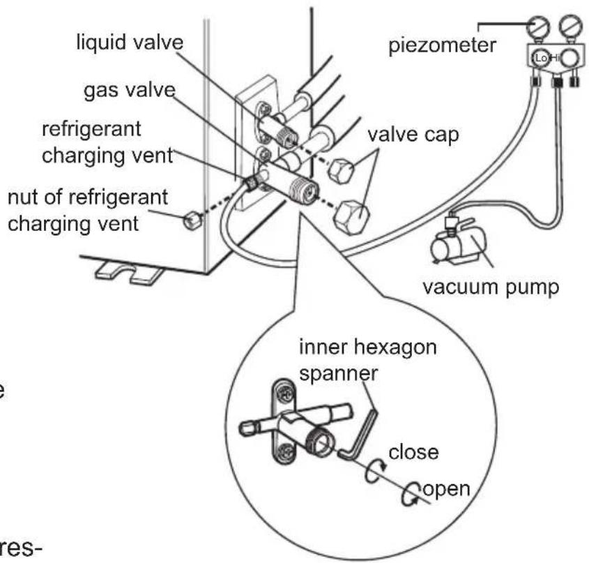
Leakage detection
- With leakage detector:
Check if there is leakage with leakage detector.
- With soap water:
If leakage detector is not available, please use soap water for leakage detection. Apply soap water at the suspected position and keep the soap water for more than 3 minutes. If there are air bubbles coming out of this position, there is a leakage.
Check after installation
- Check according to the following requirement after finishing installation.
| Items to be checked Possible malfunction | |
| Has the unit been installed firmly? | The unit may drop, shake or emit noise. |
| Have you done the refrigerant leakage test? | It may cause insufficient cooling (heating) capacity. |
| Is heat insulation of pipeline sufficient? | It may cause condensation and water dripping. |
| Is water drained well? | It may cause condensation and water dripping. |
| Is the voltage of power supply according to the voltage marked on the nameplate? | It may cause malfunction or damaging the parts. |
| Is electric wiring and pipeline installed correctly? | It may cause malfunction or damaging the parts. |
| Is the unit grounded securely? It may cause electric leakage. | |
| Does the power cord follow the specification? | It may cause malfunction or damaging the parts. |
| Is there any obstruction in the air inlet and outlet? | It may cause insufficient cooling (heating) capacity. |
| The dust and sundries caused during installation are removed? | It may cause malfunction or damaging the parts. |
| The gas valve and liquid valve of connection pipe are open completely? | It may cause insufficient cooling (heating) capacity. |
| Is the inlet and outlet of piping hole been covered? | It may cause insufficient cooling (heating) capacity or waster electricity. |
Test operation
1. Preparation of test operation
• The client approves the air conditioner.
- Specify the important notes for air conditioner to the client.
2. Method of test operation
- Put through the power, press ON/OFF button on the remote controller to start operation.
- Press MODE button to select AUTO, COOL, DRY, FAN and HEAT to check whether the operation is normal or not.
- If the ambient temperature is lower than 16°, the air conditioner cannot start cooling. 18
Configuration of connection pipe
- Standard length of connection pipe
- 5 m 7.5 m、8 m
- Min length of connection pipe
For the unit with standard connection pipe of 5 m, there is no limitation for the min length of connection pipe. For the unit with standard connection pipe of 7.5 m and 8 m, the min length of connection pipe is 3 m.
- Max length of connection pipe
Sheet 1 Max length of connection pipe Unit: m
| Max length of connection pipe | |
| 5000Btu/h (1465W) | 15 |
| 7000Btu/h (2051W) | 15 |
| 9000Btu/h (2637W) | 15 |
| 12000Btu/h (3516W) | 20 |
| 18000Btu/h (5274W) | 25 |
| Max length of yticapacyticapac connection pipe | |
| 24000Btu/h (7032W) | 25 |
| 28000Btu/h (8204W) | 30 |
| 36000Btu/h (10548W) | 30 |
| 42000Btu/h (12306W) | 30 |
| 48000Btu/h (14064W) | 30 |
- The calculation method of additional refrigerant oil and refrigerant charging amount after prolonging connection pipe
After the length of connection pipe is prolonged for 10 m at the basis of standard length, you should add 5 ml of refrigerant oil for each additional 5 m of connection pipe.
The calculation method of additional refrigerant charging amount (on the basis of liquid pipe):
(1) Additional refrigerant charging amount = prolonged length of liquid pipe × additional refrigerant charging amount per meter
(2) Basing on the length of standard pipe, add refrigerant according to the requirement as shown in the table. The additional refrigerant charging amount per meter is different according to the diameter of liquid pipe. See Sheet 2.
Configuration of connection pipe
Sheet 2. Additional refrigerant charging amount for R32
| Diameter of connection pipe mm | Indoor unit throttle | Outdoor unit throttle | ||
| Liquid pipe Gas pipe | Cooling only, cooling and heating (g / m) (g / m) | Cooling only (g / m) | cooling and heating | |
| Φ6 | Φ9.5 or Φ12 | 16 | 12 | 16 |
| Φ6 or Φ9.5 | Φ16 or Φ19 | 40 | 12 | 40 |
| Φ12 | Φ19 or Φ22.2 | 80 | 24 | 96 |
| Φ16 | Φ25.4 or Φ31.8 | 136 | 48 | 96 |
| Φ19 | - | 200 200 | 200 | |
| Φ22.2 | - | 280280 | 280 | |
Note: The additional refrigerant charging amount in Sheet 2 is recommended value, not compulsory.
Pipe expanding method
Note:
Improper pipe expanding is the main cause of refrigerant leakage. Please expand the pipe according to the following steps:
A: Cut the pipe
- Confirm the pipe length according to the distance of indoor unit and outdoor unit.
- Cut the required pipe with pipe cutter.
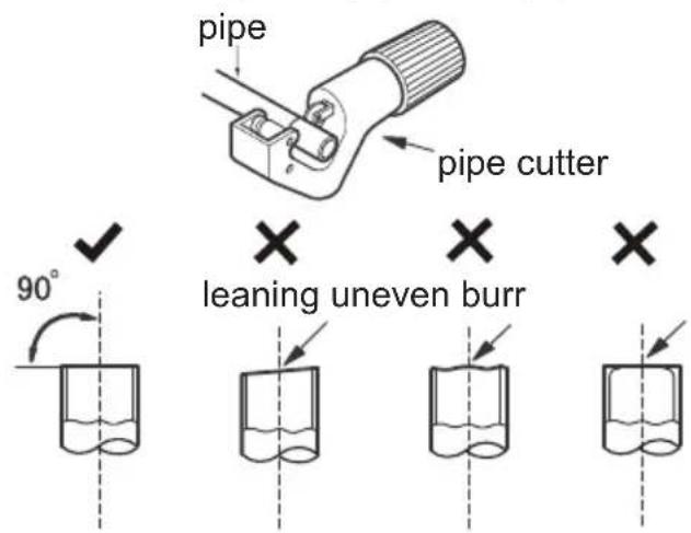
B: Remove the burrs
- Remove the burrs with shaper and prevent the burrs from getting into the pipe.
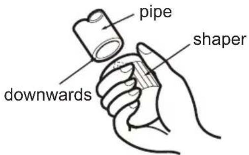
C: Put on suitable insulating pipe
D: Put on the union nut
- Remove the union nut on the indoor connection pipe and outdoor valve; install the union nut on the pipe.
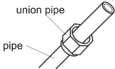
E: Expand the port
- Expand the port with expander.
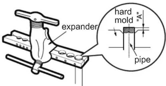
Note:
- "A" is different according to the diameter, please refer to the sheet below:
| Outer diameter (mm) | A(mm) Max Min |
| Φ6 - 6.35(1/4") | 1.3 0.7 |
| Φ9.52(3/8") | 1.6 1.0 |
| Φ12-12.7(1/2") | 1.8 1.0 |
| Φ15.8-16(5/8") | 2.4 2.2 |
F: Inspection
- Check the quality of expanding port. If there is any blemish, expand the port again according to the steps above.
smooth surface
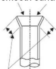
natural_image
Pure technical diagram of a cylindrical object with internal flow arrows, no text or symbols presentimproper expanding

leaning

damaged surface

crack

uneven thickness
the length is equal
Περιεχόμενα
Οδηγίες Λειτουργίας
Ψυκτικό υγρό ....63
natural_image
Warning symbol of a flame inside a triangle (no text or numbers)

Μέτρα Πρόληψης
Προσοχή
natural_image
Technical line drawing of a refrigerant air conditioner unit with ventilation grilles and fan (no text or symbols)★ Σημειώσεις:
3 Συντήρηση
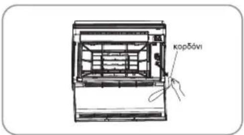
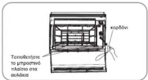
natural_image
Diagram of a door panel with arrows indicating airflow or movement, no text or symbols presentΣυντήρηση
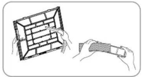
natural_image
Illustration of hands holding a grid-based object and a handheld device (no text or symbols)natural_image
Illustration of two people interacting with documents and a pen, one pointing at a document (no text or symbols present)natural_image
Illustration of two people interacting with a window, one smiling and the other holding a magnifying glass (no text or symbols)natural_image
Cartoon illustration of a cat lying on the ground surrounded by arrows and directional arrows (no text or symbols)natural_image
Cartoon illustration of a person holding a document above a window with smoke, no text or symbols presentnatural_image
Cartoon illustration of a smiling face pointing at a building with clouds, no text or symbols present5
Προφυλάξεις
natural_image
Simple line drawing of a cat-like creature with wings and legs, no text or symbols presentnatural_image
Cartoon illustration of a child lying on the floor with a cat and lightning bolt above (no text or symbols)natural_image
Illustration of a person pointing at a document with a thought bubble showing an eye (no text or symbols present)natural_image
Simple line drawing of a stylized animal head (no text or symbols)natural_image
Simple line drawing of a castle with a starburst and explosion (no text or symbols)
natural_image
Warning symbol of a flame inside a triangle (no text or numbers)


Μέτρα Πρόληψης
Προσοχή
natural_image
Line drawing of a rectangular air conditioner unit mounted on a base, showing grille and vent slots (no text or symbols)natural_image
Pure diagram of a cylindrical object with internal flow arrows, no text or symbols presentnatural_image
Warning symbol of a flame inside a triangle (no text or numbers)

Precauzioni
ISTRUZIONI PER L'USO
AVVERTENZA
Uso e Manutenzione
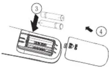
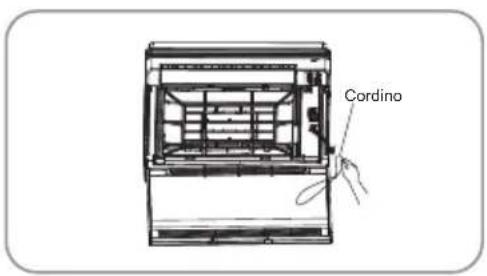
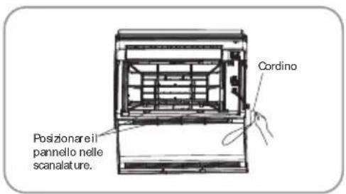
natural_image
Technical line drawing of a mechanical device with paper sheets and a flat panel (no text or symbols)Manutenzione
ISTRUZIONI PER L'USO
natural_image
Illustration of hands using a tool to interact with a grid-based object (no text or symbols visible)natural_image
Illustration of two people interacting with a document and a pen, no text or symbols presentnatural_image
Cartoon illustration of a person with a sun and a rocket above their head, no text or symbols presentnatural_image
Cartoon illustration of a cat lying on the ground surrounded by arrows and paper cutouts (no text or symbols)natural_image
Cartoon illustration of a person reading a document with a cloud, standing in front of a doorway (no text or symbols)natural_image
Cartoon illustration of a smiling character pointing at a building with clouds (no text or symbols)
Precauzioni
ISTRUZIONI PER L'USO
natural_image
Simple line drawing of a cat's head in flight (no text or symbols)natural_image
Cartoon illustration of a child playing with a megaphone and a small animal, no text or symbols presentnatural_image
Illustration of a person pointing at a document with a thought bubble showing an eye (no text or symbols present)natural_image
Simple line drawing of a cartoon animal head (no text or symbols)
natural_image
Diagram of two identical electronic components mounted on a rectangular base, with a 200mm dimension label (no text or symbols beyond the measurement)natural_image
Warning symbol of a flame inside a triangle (no text or numbers)

Precauzioni
AVVERTENZA
Uso e manutenzione
natural_image
Line drawing of a rectangular air conditioner unit mounted on a base, showing grille and vent slots (no text or symbols)Nota:
natural_image
Diagram of a cylindrical container with internal flow arrows indicating direction (no text or labels)Lunghezza uguale
Certifi cate of compliance CE
TOYOTOMI CO., LTD declares that this product complies with the general requirements pursuant to the following European Directives:
LVD: 2014/35/EU
EMC: 2014/30/EU
RoHS: (EU)2015/863
ERP: 2011/65/EU
RED: 2014/53/EU
WiFi: Wireless maximum transmit power: 18dBm
Wireless frequency range: 2412MHz - 2472MHz
Therefore the product has been marked with the C E symbol and the
Declaration of Conformity has been issued and is available to the competent authorities regulating the market.
It is prohibited to reprint or reproduction of all or part of this manual in any manner without written permission of TOYOTOMI CO., LTD
This product is made in China
- INSTALLATION INSTRUCTIONS
- Thank you for selecting our products
- Explanation of Symbols
- DANGER
- WARNING
- CAUTION
- NOTICE
- Exception Clauses
- The Refrigerant
- WARNING :
- Precautions
- Operation and Maintenance
- Attachment
- Partnamesandtheirfunctions
- INDOOR UNIT
- How to use the remote control to operate the unit
- Remote Controller Description
- How to use the remote control to operate the unit
- Note:
- ON/OFF :
- —:
- + :
- MODE :
- FAN:
- Howtousetheremotecontroltooperatetheunit
- SWING:
- I FEEL:
- 8
- SLEEP:
- TEMP:
- QUIET:
- CLOCK:
- T-ON / T-OFF:
- TURBO:
- LIGHT:
- WiFi:
- Combination of "+" and "-" buttons: About lock
- Replacement of Batteries
- ★ Notes:
- 3
- Maintenance
- Units
- Filters
- Titanium Apatite Photocatalytic Air-Purifying Filter
- NOTE
- Main tenance
- Check
- Before a long idle period
- 4
- Operating guide
- Working principle and special functions for cooling
- Principle:
- Anti-freezing function:
- Working principle and special functions for heating
- Defrosting:
- Anti-cool wind function:
- 5
- Checking before contact the service man
- 7
- Installation of indoor unit
- SELECTION OF INSTALLATION LOCATION.
- THERE ARE 2 STYLES OF INSTALLATION.
- CAUTIONS FOR INSTALLATION WHERE
- AIR CONDITIONER TROUBLEIS LIABLE
- TOOCCUR.
- Refrigerant piping
- Boring a wall hole and installing wall embedded pipe
- Drain piping
- Installing indoor unit
- 1.Preparation
- Installation
- Flaring the pipe end
- Connecting the refrigerant pipe
- Caution on piping handling
- Checking for gas leakage
- Attaching the connection pipe
- Connecting the drain hose
- Wiring
- Pipe preparation
- PIPE AND ELECTRICAL WIRE CUTTING
- REAMING
- FLARING THE PIPE END
- WIRE CONNECTION AND TAPE COVERING
- Refrigerant piping work
- Routine check after installation
- Configuration of connection pipe
- Configuration of connection pipe
- 12
- Safety operation of flammable refrigerant
- Qualification requirement for installation and maintenance man
- Installation notes
- Maintenance notes
- Welding
- Filling the refrigerant
- Safety instructions for transportation and storage
- Content
- Operation Notices
- Installation Notice
- Installation
- Test and operation
- WARNING:
- NOTICE:
- Parts name
- Installation dimension diagram
- Safety precautions for installing and relocating the unit
- To ensure safety, please be mindful of the following precautions.
- Tools for installation
- Selection of installation location
- Basic requirement
- Outdoor unit
- Requirements for electric connection
- Safety precaution
- Grounding requirement
- Installation of outdoor unit
- Step one: fix the support of outdoor unit (select it according to the actual installation situation)
- Step two: install drain joint (Only for cooling and heating unit)
- Step three: fix outdoor unit
- Step four: connect indoor and outdoor pipes
- Step five: connect outdoor electric wire
- Step six: neaten the pipes
- Vacuum pumping
- Use vacuum pump
- Leakage detection
- Check after installation
- Test operation
- Preparation of test operation
- Method of test operation
- Pipe expanding method
- Περιεχόμενα
- Οδηγίες Λειτουργίας
- Μέτρα Πρόληψης
- Προσοχή
- ★ Σημειώσεις:
- Συντήρηση
- Συντήρηση
- Προφυλάξεις
- Precauzioni
- AVVERTENZA
- Uso e Manutenzione
- Manutenzione
- Certifi cate of compliance CE
Brand : Toyotomi
Model : CON28INECR32/CON28OUECR32
Category : Air-conditioner