
THN/THG-A56SZ - Air conditioner Toyotomi - Free user manual and instructions
Find the device manual for free THN/THG-A56SZ Toyotomi in PDF.


User questions about THN/THG-A56SZ Toyotomi
0 question about this device. Answer the ones you know or ask your own.
Ask a new question about this device
Download the instructions for your Air conditioner in PDF format for free! Find your manual THN/THG-A56SZ - Toyotomi and take your electronic device back in hand. On this page are published all the documents necessary for the use of your device. THN/THG-A56SZ by Toyotomi.
USER MANUAL THN/THG-A56SZ Toyotomi
THN/THG-A56VR22 THN/THG-A56SZ
THN/THG-A71VR22 THN/THG-A71SZ
Thank you for purchasing our product.
- Before using this product, be sure to read this Instruction Manual to ensure proper usage. Please keep this manual for later reference.
- Improper use of this product may result in a malfunction, failure, unexpected accident, or create a potential hazard.
natural_image
Line drawing of two hands pressing down on a cylindrical object (no text or symbols)natural_image
Line drawing of a cylindrical object with a handle and internal slots, resembling a mechanical or electronic component (no text or symbols)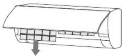
natural_image
Diagram of a car air conditioner unit with cooling fins and airflow direction arrow (no text or labels)natural_image
Illustration showing a car being cleaned on a grid surface next to a bowl of soap and a bottle (no text or symbols)natural_image
Diagram of a car air conditioner unit with cooling fins and airflow direction arrow (no text or labels)
ΠΡΟΣΟΧΗ
natural_image
Technical line drawing of a mechanical bracket assembly (no text or symbols)natural_image
Diagram of a hand holding a curved object with a vertical rod inserted, showing motion direction (no text or symbols)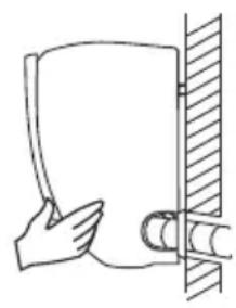
natural_image
Simple line drawing of a hand holding a cup next to a wall with a cylindrical object (no text or symbols)Εξωτ.Μονάδα
Εξωτ.Μονάδα
Inverter
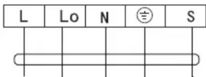
Εξωτ.Μονάδα
DANGER: This symbol indicates a dangerous situation that if not avoided could lead to death or serious injury.
WARNING: This symbol indicates a dangerous situation that if not avoided could lead to death or serious injury.
ATTENTION: This symbol indicates a dangerous situation that if not avoided could lead to minor or moderate damage.
NOTICE: Indicates important information indicate the risk of material damage.
Appliance filled with flammable gas R32. If the refrigerant is leaked and exposed to an external ignition source, there is a risk of fire.
Before use the appliance, read the owner's manual first.

Before install the appliance, read the installation manual first.
Before repair the appliance, read the service manual first.
Refrigerant R32: GWP 675
THE REFRIGERANT
- To realize the function of the air conditioner unit, a special refrigerant circulates in the system. The used refrigerant is the fluoride R32, which is specially cleaned. The refrigerant is flammable and inodorous. Furthermore, it can leads to explosion under certain conditions. But the flammability of the refrigerant is very low. It can be ignited only by fire.
- Compared to common refrigerants, R32 is a nonpolluting refrigerant with no harm to the ozonosphere. The influence upon the greenhouse effect is also lower. R32 has got very good thermodynamic features which lead to high energy efficiency. The units therefore need a less filling.
WARNING
- DO NOT use means to accelerate the defrosting process or to clean, other than those recommended by the manufacture.
- If repair or maintenance is necessary, contact your nearest authorized Service Centre. Any repairs carried out by unqualified personnel may be dangerous.
- The appliance shall be stored in a room without continuously operating ignition sources. (for example: open flames, an operating gas appliance or an operating electric heater.) DO NOT pierce or burn the air conditioner.
- Appliance shall be installed, operated and stored in a room with a floor area larger than 5m ^2 .
- Air conditioner refrigerant can not charge more than 1.7kg.
- The storage of the air conditioner should be able to prevent mechanical damage caused by accident.
- Air conditioner must be installed with stop valve cover.
- Appliance filled with flammable gas R32. For repairs, strictly follow manufacturer's instructions only. Be aware that refrigerants do not contain odor and may be tasteless.
- Read carefully the instruction manual before first use.
PRECAUTIONS

WARNING
Operation and Maintenance
☐ This appliance can be used by children aged from 8 years and above and persons with reduced physical, sensory or mental capabilities or lack of experience and knowledge if they have been given supervision or instruction concerning use of the appliance in a safe way and understand the hazards involved.
☐ Children shall not play with the appliance.
☐ Cleaning and user maintenance shall not be made by children
without supervision.
☐ DO NOT connect air conditioner to multi-purpose socket. Otherwise, it may cause fire hazard.
□ Always disconnect power supply when cleaning air conditioner. Otherwise, it may cause electric shock.
☐ If the supply cord is damaged, it must be replaced by the manufacturer, its service agent or similarly qualified persons to avoid a hazard.
☐ DO NOT use the air conditioner in lightning storm weather. Lightning might cause damage.
☐ DO NOT wash the air conditioner with water to avoid electric shock.
☐ DO NOT use liquid or corrosive cleaning agent wipe the air conditioner. Doing this may cause electric shock or damage to the unit.
☐ DO NOT spray water on indoor unit. It may cause electric shock or malfunction.
☐ After removing the filter, do not touch fins to avoid injury.
☐ DO NOT use fire or hair dryer to dry the filter to avoid deformation or fire hazard.
☐ Cleaning or maintenance MUST NOT be made by children. Supervision must always be provided by an adult responsible for their safety.
□ Maintenance must be performed by qualified professionals. Otherwise, it may cause personal injury or damage. In such case warranty will be invalid.
☐ DO NOT repair air conditioner by yourself. It may cause electric shock or damage. Please contact dealer when you need to repair air conditioner.
☐ DO NOT insert fingers or objects into air inlet or air outlet. It may cause personal injury or damage.
☐ DO NOT block air outlet or air inlet. It may cause malfunction.
☐ DO NOT spill water on the remote controller, otherwise the remote controller may be broken.
☐ When below phenomenon occurs, please turn off air conditioner and disconnect power immediately and then contact the dealer or qualified professionals for service.
- Power cord is overheating or damaged.
- There is abnormal sound during operation.
- Circuit break trips off frequently.
- Air conditioner gives off burning smell.
- The refrigerant is leaking from indoor unit.
☐ If the air conditioner operates under abnormal conditions, it may cause malfunction, electric shock or fire hazard.
☐ When turning on or turning off the unit by emergency operation switch, please press this switch with an insulating object other than metal.
☐ DO NOT step on top panel of outdoor unit or put heavy objects. It may cause damage or personal injury.
☐ Installation must be performed by qualified professionals. Otherwise, it may cause personal injury or damage.
☐ Must follow the electric safety regulations when installing the unit.
□ According to the local safety regulations, use qualified power supply circuit and circuit break.
☐ Install the circuit break. If not, it may cause malfunction.
☐ An all-pole disconnection switch having a contact separation of at least 3mm in all poles should be connected in fixed wiring.
☐ Including a circuit break with suitable capacity, please note the following table. Air switch should be included magnet buckle and heating buckle function, it can protect the circuit-short and overload.
☐ Air Conditioner should be properly grounded. Incorrect grounding may cause electric shock.
□ Don't use unqualified power cord.
☐ Make sure the power supply matches with the requirement of air conditioner. Unstable power supply or incorrect wiring may result in electric shock, fire hazard or malfunction. Please install proper power supply cables before using the air conditioner.
☐ Properly connect the live wire, neutral wire and grounding wire of power socket.
☐ Be sure to cut off the power supply before proceeding any work related to electricity and safety.
☐ DO NOT put through the power before finishing installation.
☐ If the supply cord is damaged, it must be replaced by the manufacturer, its service agent or similarly qualified persons to avoid a hazard.
☐ The temperature of refrigerant circuit will be high, please keep the interconnection cable away from the copper tube.
☐ The appliance shall be installed in accordance with national wiring regulations.
☐ Installation must be performed in accordance with applicable local regulations by authorized licensed personnel only.
☐ The air conditioner is the first-class electric appliance. It must be properly grounding with specialized grounding device by a professional. Please make sure it is always grounded effectively, otherwise it may cause electric shock.
☐ The yellow-green wire in air conditioner is grounding wire, which can't be used for other purposes.
☐ The grounding resistance should comply with national electric safety regulations.
☐ The appliance must be positioned so that the plug is accessible.
☐ All wires of indoor unit and outdoor unit should be connected by a professional.
☐ If the length of power connection wire is insufficient, please contact the supplier for a new one. Avoid extending the wire by yourself.
☐ For the air conditioner with plug, the plug should be reachable
after fi nishing installation.
☐ For the air conditioner without plug, a circuit break must be installed in the line.
☐ If you need to relocate the air conditioner to another place, only the qualified person can perform the work. Otherwise, it may cause personal injury or damage.
☐ Select a location which is out of reach for children and far away from animals or plants. If it is unavoidable, please add the fence for safety purpose.
☐ The indoor unit should be installed close to the wall.
☐ Instructions for installation and use of this product are provided by the manufacturer.
☐ The air conditioner is not allowed to use in a room that has running fire (such as fire source, working coal gas ware, operating heater).
☐ It is not allowed to drill hole or burn the connection pipe. These tasks shall only be done by a licensed technician to ensure your safety.
☐ Leak test is a must after installation.
- Don’t install the air conditioner in a place where there is flammable gas or liquid. It may cause fire even explosion.
This product contains fl uorinated greenhouse gases
Refrigerant leakage contributes to climate change. Refrigerant with lower global warming potential (GWP) would contribute less to global warming than a refrigerant with higher GWP if leaked to the atmosphere. This appliance contains a refrigerant fluid with a GWP equal to [675] . This means that if 1 kg of this refrigerant fluid would be leaked to the atmosphere the impact on global warming would be [675] times higher than 1 kg of CO_2 over a period of 100 years. Never try to interfere with the refrigerant circuit yourself or disassemble the product yourself. These tasks should be carried
only by licensed authorized technician.
Ensure no following objects are under the indoor unit:
■ Microwaves, ovens and other hot objects.
■ Computers and other high electrostatic appliances.
- Sockets that plug frequently.
The joints between indoor and outdoor unit shall not be reused, unless after re-fl aring the pipe.
The specifications of the fuse are printed on the circuit board, such as: 3.15A/250V AC, etc.
If your air conditioner is not fitted with a supply cord and a plug, an anti-explosion all-pole switch must be installed in the fixed wiring and the distance between contacts should be no less than 2.5 mm.
If your air conditioner is permanently connected to the fixed wiring, an anti-explosion residual current device (RCD) having rated residual operating current not exceeding 30 mA should be installed in the fixed wiring.
Power supply circuit should have leakage protector and air switch of which the capacity should be more than 1.5 times of the maximum current.
USEFUL TIPS
Conditions where the Air Conditioner might not run normally
■ Within the temperature range provided in following table, the air conditioner may stop running and other anomalies may arise.
| Cooling | Outdoor | >43°C (Για T1) |
| >52°C (Για T3) | ||
| Indoor <18 | °C | |
| Heating | Outdoor | >24°C |
| <-7°C | ||
| Indoor >27 | °C |
- When temperature is too high, the air conditioner may activate the automatic protection device, so that the air conditioner could be shut down.
- When temperature is too low, heat exchanger of the air conditioner may freeze, leading to water dripping or another malfunction.
In long-term cooling or dehumidification with a relative humidity of above 80% (doors and windows open), there might be water condenses or dripping near the air outlet.
■ T1 and T3 refer to ISO 5151.
NOTES FOR HEATING
■ The fan of indoor unit will not start running immediately after the heating is started to avoid blowing out cold air.
- When it is cold and wet outside, the outdoor unit will develop frost over the heat exchanger which will decrease the heating capacity. Then the air conditioner will start defrost function.
■ During defrost, the air conditioner will stop heating for about 5-12 minutes.
- Vapor may come out from the outdoor unit during defrost. This is not a malfunction, but a result of fast defrost.
■ Heating will resume after defrost is complete.
NOTES FOR TURNING OFF THE AIR CONDITIONER
- When the air conditioner is turned off, the main controller will automatically decide whether to stop immediately or after running for several seconds with lower frequency and lower air speed.
EMERGENCY OPERATION
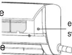
If the remote controller is broken or lost, use emergency switch button to operate the air conditioner.
If this button is pushed when unit is OFF, the air conditioner will operate in AUTO mode.
■ If this button is pushed when unit is ON, the air conditioner will stop running.
ADJUSTMENT OF AIR FLOW DIRECTION
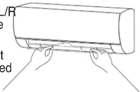
■ Use U/D SWING up-down swing and L/R SWING left-right swing buttons on the remote controller to adjust the air flow direction.
- For the models without L/R SWING left-right swing function, the fi ns has to be moved manually.
natural_image
Line drawing of hands pressing down on a cylindrical object (no text or symbols)Note: Move the fins while the air conditioner is not in operation, or your fingers might be insured, and unit can also be damaged.
Never place your hands into the air inlet or outlet when the air conditioner is in operation.
PAY ATTENTION
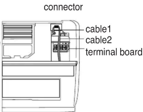
■ Open front panel of indoor unit.
■ The connector must not touch the terminal board, and is positioned as shown in Fig.
CLEAN AND MAINTENANCE
CLEANING THE INDOOR UNIT
- Turn off the unit and cut off the power supply. Wait after that at least 5 minutes before you start cleaning of the unit otherwise there might be the risk of electric shock.
- Clean the indoor unit (only the outside plastic parts) with dry or damp soft cloth in cold water. Do not spray or spill the unit in order to clean it.
- Clean air filters regularly, in order to avoid accumulation of dust that might affect the good performance of the air conditioner. After removing the air fiters, do not touch the metallic parts. It might cause injury.
- Do not use water which temperature that exceeds 40^ C to clean the front panel. Otherwise it may cause deformation or discoloration.
- Do not use liquids, hard detergents, thinner, gasoline or any other chemical product for cleaning. Otherwise plastic parts of the air conditioner might be damaged or even cause electric shock.
CLEANING THE AIR FILTERS
■ Remove pre-filters and healthy filters
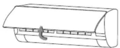
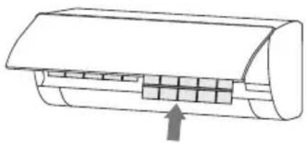
- Use both hands to open the front panel for an angle from both ends of the panel in accordance with the direction of the arrow, until it clamps in a certain position. Lift gently the pre-filters until they unclench, release them from the slot and remove them.
natural_image
Simple line drawing of a cylindrical object with a handle and internal structure (no text or symbols)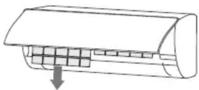
natural_image
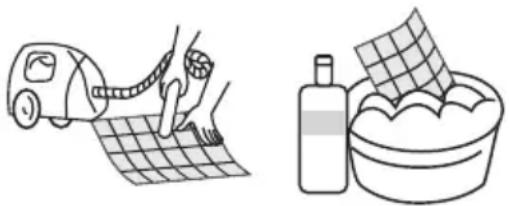
Diagram of a car air conditioner unit with cooling fins and airflow direction arrow (no text or labels)- Clean pre-filters with a vacuum cleaner or wash them in cold water and let them dry well in shady area before you reinstall them. Clean healthy filters with a vacuum cleaner or shake them outdoors. CAUTION! Do not clean healthy filters with water or other kind of liquid otherwise their performance will be damaged.
natural_image
Illustration showing a hand using a tape measure to clean a grid-patterned surface next to a washing bottle and bowl (no text or symbols)- Reinstall the dried filter in reverse order of removal, then close the front panel back to its original position.
natural_image
Diagram of a car air conditioner unit with cooling fins and heat exchanger (no text or labels)
ATTENTION
■ Pre-filters shall be cleaned at least one time every three months. If the environment has a lot of dirt, it is recommended to clean the filters more frequently.
■ Do not touch the fins of indoor unit when you take off the filters. It may cause injury.
■ Do not use fire or hair dryer to dry the filters. It might cause deformation, fire, injury.
- Do not clean the healthy filters with water or other kind of detergent. Healthy filters must be cleaned only with a vacuum cleaner or by shaking them outdoors.
CHECK BEFORE USE
- Make sure all air inlets and outlets of the units are unblocked.
- Make sure that nothing blocks in the water outlet of the drain pipe, and immediately clean it up if any.
- Make sure the ground wire is reliably grounded.
- Make sure the remote controller batteries are installed, and power is sufficient
- Make sure that there is not damage in the mounting bracket of the outdoor unit. If any, please contact the local service center.
MAINTENANCE
- Cut off the power source of the air conditioner, turn off the main power switch and remove batteries from the remote controller.
- Clan filters and unit body.
- Remove dust and debris from outdoor unit.
- Check whether there is damage in the mounting bracket of the outdoor unit and if any please contact the local service center.
IMPORTANT NOTICE FOR PROPER RECYCLING
■ Many of the packaging materials are recyclable. Please dispose of the packaging materials in an environmentally safe manner.
In case you want to dispose your old air conditioner, contact the local authorities in order to be delivered to a special collection and recycling center for electronic and electrical equipment.
TROUBLESHOOTING
Do not repair the air conditioner by yourself as wrong service and maintenance may cause electric shock, fire or explosion. Please contact the authorized service and let the licensed professional conduct the service and maintenance of your air conditioner. Please check below cases before contact the service as problem might be solved without the interference of service.
| PHENOMENON PROBLEM - SOLUTION | |
| The air conditioner does not work | Power failure✓ Wait until power recovers |
| Power plug may be loosed out from the socket✓ Place properly the plug in the socket | |
| Power switch fuse may be blow✓ Replace the fuse | |
| TIMER is on. The time for timing boot is yet to come✓ Wait or cancel TIMER setting | |
| The air conditioner can’t run after the immediate start-up after it is shut down | If the air conditioner is turned on immediately after it is turned off, the protective delay switch will delay the operation for 3 to 5 minutes. This is self-compressor protection procedure. |
| Air conditioner stops running after it starts up for a while | Setting temperature has been reached✓ It is a normal function phenomenon |
| May be at defrost state✓ It will automatically restore and run again after defrosting | |
| TIMER is on✓ Wait or cancel TIMER setting | |
| Cooling or Heating performance is not satisfying | Excessive accumulation of dust on filter is blocking air inlet and outletClean the air filters and remove the obstacles from air inlet and outlet |
| Voltage is too lowWait until voltage resumes to normal levels | |
| Air conditioner is working in AUTO modeDuring AUTO mode, temperature cannot be changed. If you wish to change the temperature change the mode of air conditioner | |
| The angle of the louver blades is too smallRegulate the angle of the louver blades so the air flow can run freely | |
| Poor Cooling or Heating may be caused by open doors and windows.Close the doors and windows | |
| Mode setting is incorrect. Temperature and fan speed settings are not appropriateRe-select the mode and set the appropriate temperature and fan speed | |
| Indoor unit blows out odor | Odor from the environment has been accumulated inside indoor unitClean the air filters and activate the self-clean function |
| There is sound of running water during operation | During turning on or turning off the air conditioner, when compressor stops and starts again, the sound of running water may be heard from the indoor unitThis is the sound of refrigerant flow and it is normal |
| During turning on or turning off the air conditioner there is a cracking sound | During turning on or turning off the air conditioner you may hear a cracking sound from the indoor unitDue to the temperature change, contraction / expansion is caused on the plastic parts of the air conditioner. This is normal |
| Indoor unit makes abnormal sound | During turning on or turning off the air conditioner the sound of compressor or fan is heard |
| When defrost function starts a different sound is heard√ Flow of refrigerant changes and the different sound is normal | |
| A lot of dust is accumulated on filters√ Clean the air fi Iters | |
| During TURBO operation the sound is a little bit louder√ This is normal | |
| Water drops are over the surface of the indoor unit | When ambient humidity is high, water drops will be accumulated around the air outlet or the panel√ This is a normal physics phenomenon |
| Prolonged cooling run in open space produces water drops√ Close the doors and windows | |
| The angle of the louver blades is too small√ Regulate the angle of the louver blades so the air flow can run freely | |
| During Cooling operation, indoor unit outlet sometimes will blow out mist | When the indoor temperature and humidity are high, it happens sometimes√ This happens because the indoor air is cooled rapidly. After it runs form some time, the indoor temperature and humidity will be reduced, and the mist will disappear. |
| Air conditioner stopped suddenly to operate | There is interference, like thunder or wireless devices etc√ Disconnect from power. Reconnect to power and operate again the air conditioner |
| Indoor unit does not accept remote controller's signal or remote controller does not work | ■ There is significant interference (e.g. static electricity, constant voltage)✓ Turn off the air conditioner, pull out the plug from outlet. Wait 3 minutes then put the plug to the outlet and restart the function of the air conditioner |
| ■ Remote controller is out of range✓ The distance between signal center and receiving window should be no more than 8m | |
| ■ There are obstacles between signal center and window receiver✓ Remove obstacles | |
| ■ Signal center of remote controller cannot communicate with window receiver of the indoor unit✓ Choose the right angle where signal center of remote controller can communicate with window receiver of indoor unit | |
| ■ The display on remote controller is fuzzy or there is no display at all✓ Check the batteries. If their power is low, replace them | |
| ■ No display on remote controller✓ Check if the remote controller is damaged. If yes, please replace it | |
| ■ There is fluorescent lamp in the room✓ Take remote controller closer to the window receiv of indoor unit✓ Turn of the fluorescent lamp and try again | |
| If any of the following cases occur, turn off the unit, pull out the plug from the socket and contact the authorized service of Γ.E.ΔHMHTPIOY A.E.E. +30 210 5386490,TOYOTOMI ITALIA S.R.L. +39 039 6080392,TOYOTOMI EUROPE SALES B.V. +31 (0)413 82 02 95,TOYOTOMI EUROPE SALES SPAIN S.A. +34 91 6895583 | |

CAUTION
In case any of the following cases occur, please turn off the unit, pull out the plug from the socket and contact the authorized service for repair.
– Power cord has been overheated or damaged.
– Unusual sound is heard during operation.
– Circuit breaker often shuts down.
– Burning smell comes out of the air conditioner.
– There is a leakage from the indoor unit.
■ DO NOT repair or re-install the air conditioner by yourself.
In case the air conditioner continues to work under unusual conditions, it might cause malfunction, electric shock, fire or injury.
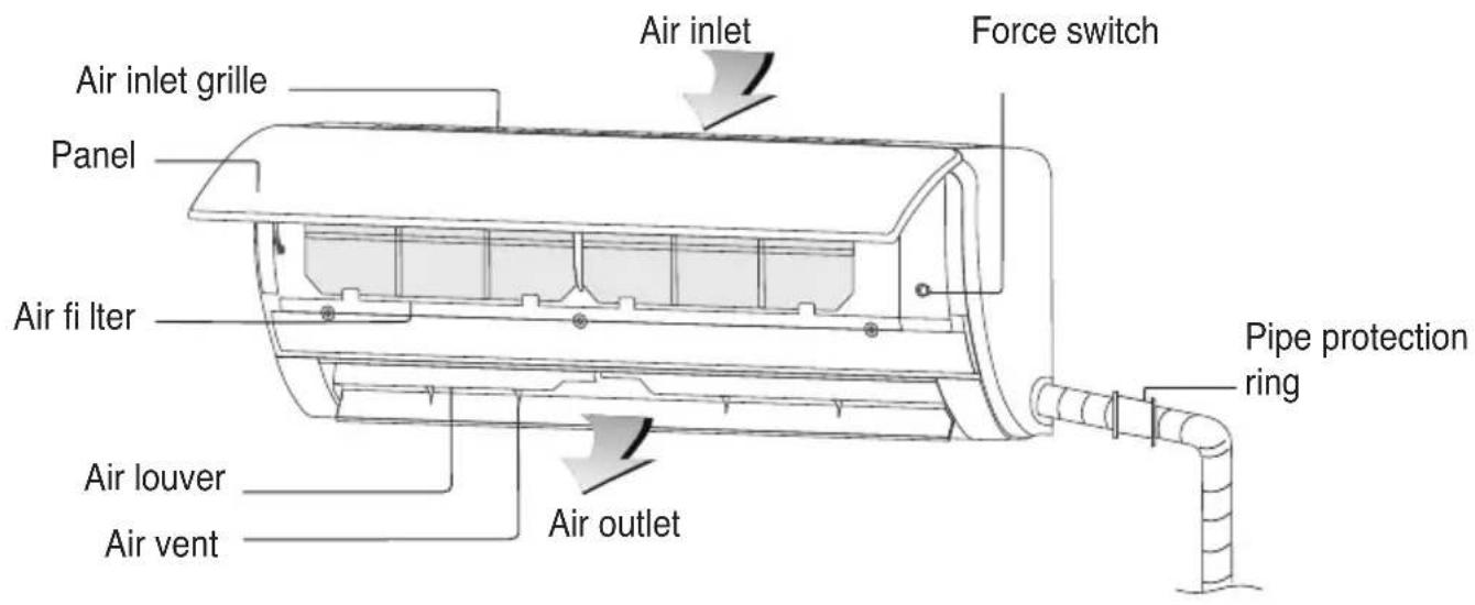
PART DESCRIPTION
INDOOR UNIT
OUTDOOR UNIT
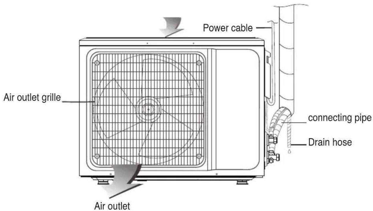
Symbols or its location may be different from the photo, depending on the model you have chosen.
BUTTONS DESCRIPTION
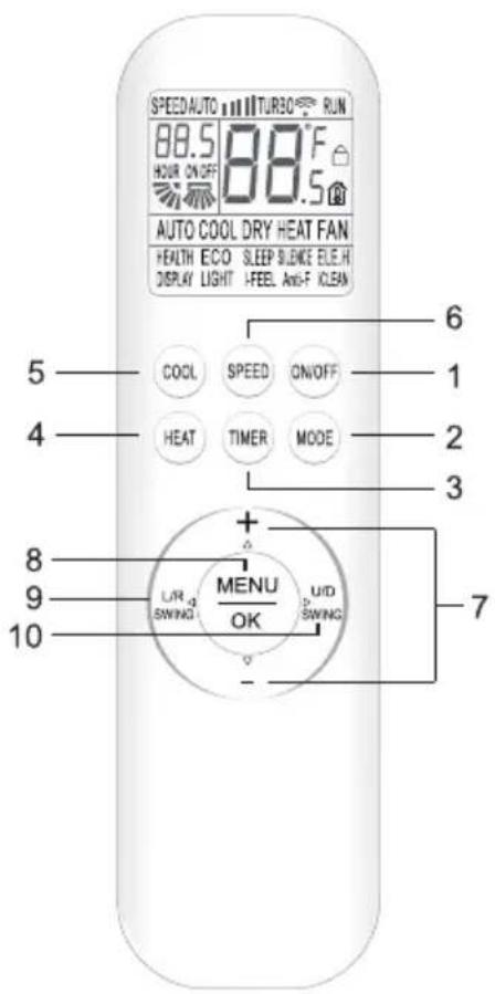
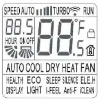
Note: When you power on remote controller for the first time, all functions will be displayed on the screen. After a while only those corresponding to current operation will be displayed
INSTRUCTIONS FOR PROPER USE OF THE REMOTE CONTROLLER
- The transmitter of remote controller, which is located on the front part of remote controller, must point to indoor unit signal receiver.
- Maximum distance between transmitter of remote controller and indoor unit signal receiver should be 8 meters.
- Make sure that there are no obstacles between transmitter of remote controller and indoor unit signal receiver.
- Do not drop down or through away remote controller.
- Do now allow any kind of liquid to enter inside remote controller.
- Before using remote controller for the first time, install properly batteries and make sure «+» & «-» poles are properly positioned.
- Use two AAA batteries. Do not use rechargeable batteries.
- Do not expose the remote controller directly to the sunlight or excessive heat (e.g. oil radiator)
- If you don't use remote controller for a long period, remove the batteries to avoid possible leakage and damage.
-
If you cannot hear beep sound to each command you place through the remote controller or if characters are not clear on the screen, then you should change the batteries.
-
Make sure that when you replace batteries both are new. Do not place new batteries with old or different kind of batteries. This may damage the remote controller.
- Properly dispose the discarded batteries.
Note:
This is a universal remote controller, which provides all the function buttons. Some of the buttons may not function, depending on the specific air conditioner you purchased. For the functions that are not available to the product you purchased, pressing the corresponding button will simply have no response.
BUTTON DESCRIPTION
1. BUTTON ON/OFF
Press this button to activate your air conditioner. Press it again to deactivate it.
2. BUTTON MODE
Press this button to select the running mode as follows:

flowchart
graph LR
    A["→AUTO"] --> B["COOL"]
    B --> C["DRY"]
    C --> D["HEAT"]
    D --> E["FAN"]
By pressing buttons “+” or “-” you can set temperature range between 16°C (60°F) \~ 32°C (90°F). Indication will change every time you push the button.
Note: During AUTO mode, you cannot set the temperature.
Note: During FAN mode you cannot set the temperature.
Note: During DRY mode you cannot set FAN speed.
3. BUTTON TIMER
- Press this button when air conditioner is ON, to activate TIMER OFF. Press this button when air conditioner is OFF, to activate TIMER ON.
- Press this button once and "ON(OFF)" will flash. Press buttons "+" or "-" to set the number of hours in which the unit will be turned ON/OFF, with an interval of 0.5 hour and a range of 0.5-24 hours.
- Press this button again to confirm the setting. "ON(OFF)" will stop flashing.
- If TIMER button is not pressed within 10 seconds after the "ON(OFF)" start fl ashing, timer setting will be exited.
- If TIMER setting is confirmed, pressing this button again will cancel it.
4. BUTTON HEAT
Press this button to set HEAT mode.
5. BUTTON COOL
Press this button to set COOL mode.
6. BUTTON SPEED
Press this button to select fan speed as follows:

flowchart
graph LR
    A["Low"] --> B["Mid"]
    B --> C["High"]
    C --> D["Turbo"]
    D --> E["Auto"]
    subgraph Stage 1
        F["(1)"] --> G["(III)"]
        G --> H["(III)"]
        H --> I["(TURBO)"]
        I --> J["(AUTO)"]
    end
Note: AUTO fan speed is not available in FAN mode.
7. BUTTONS “+” or “-”
Every time you press button “+”, temperature setting will increase by 1^ C and every time you press button “-” temperature setting will decrease 1^ C.
Temperature setting range is 16^ C ( 60^ F) \~ 32^ C ( 90^ F).
Note: During AUTO and FAN modes you cannot set temperature.
8. BUTTON MENU/OK
Press this button to enter the ECO, HEALTH, SLEEP modes. Press △, ▽, ◀, ▷ buttons to choose the function you want. To confirm this function press button OK.
Note: Through MENU button, by pressing buttons △, ▽, ◀, ▶ you will see the sign of desired function flashing on remote controller's screen. Then you can set this function.
9. BUTTON L/R SWING
Press this button to activate vertical louvers (left/right swing). Press it again to fix the desired swing position.
10. BUTTON U/D SWING
Press this button to activate horizontal louver (up/down). Press it again to fix the desired swing position.
Note: When air conditioner is ON, press and hold this button for 3 seconds. In this way you activate the rated swinging. Press it again to fix the desired swing position.
11. HEALTH FUNCTION
When the unit is on, press button MENU and then buttons △, ▽, ◀, ▶ to choose HEALTH indication that flashes on remote controller's screen. Press button OK to activate or deactivate lonizer HEALTH.
12. ECO FUNCTION
- During Cooling mode, air conditioner can enter in ECO mode. During ECO mode the air conditioner sets automatically proper room temperature with the lowest power consumption. Air conditioner can work under ECO mode up to 8 hours. After 8 hours ECO function will be deactivated.
- ÉCO mode will be cancelled if you change working mode or if you deactivate the remote controller.
- During Cooling mode, press MENU button and then press , , , buttons to choose ECO indication that flashes on remote controller's screen. Press button OK to activate or deactivate energy saving ECO function.
Note: Power consumption is affected by ambient (not set temperature) and house structure. When ambient temperature is high or the house is very big with big losses (e.g. very high ceiling, old windows etc), use ECO mode with caution.
13. SLEEP FUNCTION
- When unit is ON, press MENU button and then press buttons , , , to choose SLEEP indication that flashes on remote controller's screen. Press button OK to activate or deactivate SLEEP mode.
- After 10 hours under SLEEP mode, SLEEP mode stops, and the air conditioner will continue under the initial function.
Note: SLEEP function cannot be activated during FAN and AUTO modes.
During SLEEP mode, there are no indications on indoor unit.
14. SILENCE FUNCTION
When unit is ON, press MENU button and then press buttons △, ▽, ◀, ▶ to choose SILENCE indication that flashes on remote controller's screen. Press button OK to activate or deactivate SILENCE mode.
15. ELE-H FUNCTION (This function is not available)
When unit is ON, press MENU button and then press △, ▽, ◀, ▶ to choose ELE.H indication that flashes on remote controller's screen. Press button OK to activate or deactivate the auxiliary heating function.
16. DISPLAY FUNCTION
Press MENU button and then press buttons △, ∇, ◀, ▷ to choose DISPLAY H indication that flashes on remote controller's screen. Press button OK to activate or deactivate mode indications that lights on indoor unit during operation. This function is suitable especially during night.
17. LIGHT FUNTION
– Air conditioner will activate or deactivate automatically mode indications that
lights on indoor unit during operation based on ambient brightness.
- When unit is ON, press MODE button and then press buttons , , , to choose LIGHT indication that flashes on remote controller's screen. Press button OK to activate or deactivate LIGHT function.
18. I-FEEL FUNCTION
- When unit is on Cooling mode, press MENU button and then press buttons , , , to choose I-FEEL indication that flashes on remote controller's screen. Press button OK to activate or deactivate the comfortable wind to the user.
- When I-FEEL mode is activated, fan speed is set to Auto and swing function will be cancelled. During I-FEEL function, the operations that turns off the unit, change running mode and activate SLEEP function, FAN speed and SWING mode, deactivates automatically I-FEEL function and resume the initial running mode.
19. ANTI-F FUNCTION (Auto Clean):
- When the unit is closed under the modes of cooling, dry or auto (cooling), it will continue to operate for about 3 minutes to dry the moisture on the evaporator, so as to prevent accumulation of bacteria on the evaporator, which causes fungus and a strange smell and is harmful to the health.
- When the unit is off, press the «MENU» button, then press (+) , (-) , L/R SWING and U/D SWING and select the «Anti-F» function that will blink, by pressing the «OK» button that flashes the «Anti-F» indicator, which it will activate or deactivate the « Anti-F « function.
20. iCLEAN FUNCTION (Sterilization 56°C)
- Air conditioner will automatically clean dust from the evaporator and will dry the moisture.
- When unit is OFF, press MENU button and then press buttons , , , to choose iCLEAN indication that flashes on remote controller's screen. Press button OK to activate or deactivate Sterilization function.
- Sterilization function stops automatically after 30 minutes.
21. CHILD-LOCK FUNCTION
- Press simultaneously buttons HEAT and MODE for at least 3 seconds, to activate or deactivate LOCK function.
- When LOCK function is activated, indication □ will appear on remote controll screen.
** Function ELE.H, is not available.
8°C Heating function
Only in the heating mode in the power-on state, press the «MODE» and «+» buttons at the same time above 3 seconds to turn on or off the 8°C Heating function.
After turning on the 8°C Heating function.
a Press the «HEAT» button or switch to mode, or select the sleep function, all can exit 8°C Heating function.
b Press the «SPEED», «+», «-» button is all non-effective.
c Fahrenheit/Celsius switching function is non effective.
d Turn off and on the unit again, 8°C Heating function is still retained.
e Press the «MENU» button, ELE.H function is not selectable.
USAGE FOR MODE
Auto Operation mode
-
Press the «ON/OFF» button, the air-conditioner starts to operate.
-
Press the «MODE» button, select auto operation mode.
-
By pressing the «SPEED» button, you can select fan speed from Low, Mid, High, Auto.
-
Press the «ON/OFF» button again, the air-conditioner stops.
Note: In the Auto Mode, the temperature setting is non-effective.
Cool/Heat operation Mode
-
Press the «ON/OFF» button, the air-conditioner starts to operate.
-
Press the «MODE» button, select cool or heat operation mode
-
By pressing the «+» or «-» button, you can set temperature from 16C (60°F) to 32°C(90°F), the display changes as you press the button.
-
By pressing the «SPEED» button, you can select fan speed from Low, Mid, High, Turbo, Auto.
-
Press the «ON/OFF» button again, the air-conditioner stops.
Note: The cold wind type has no heating function.
Fan operation Mode
-
Press the «ON/OFF» button, the air-conditioner starts to operate.
-
Press the «MODE» button, select fan operation mode.
-
By pressing the «SPEED» button, you can select fan speed from Low, Mid, High.
-
Press the «ON/OFF» button, again, the air-conditioner stops.
Note: In the fan mode, the temperature settings is non-effective.
Dry Operation mode
-
Press the «ON/OFF» button, the air-conditioner starts to operate.
-
Press the «MODE» button, select dry operation mode.
-
By pressing the «+» or «-» button, you can set temperature from 16C (60°F) to 32°C (90°F), the display changes as you press the button.
-
Press the «ON/OFF» button again, the air-conditioner stops.
Note: In the dry mode, the speed settings is non-effective.
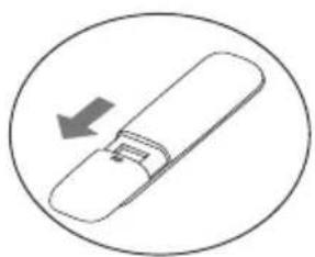
Insert Batteries to remote controller
natural_image
Simple line drawing of a USB flash drive inside a circle (no text or symbols)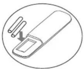
natural_image
Simple line drawing of a pen-like object with two cylindrical pins, enclosed in an oval (no text or symbols)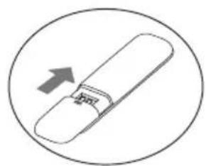
natural_image
Simple line drawing of a rolled-up document or scroll with an arrow indicating upward motion (no text or symbols)- Slide downwards the cover, as it shows the arrow in the first picture, to open it.
- Insert two new batteries (7#). Make sure that you placed the batteries to correct electric poles (+&-).
- Slide upwards the cover, as it shows the arrow in the third picture, to close it.

ATTENTION
In case below phenomenon occurs, please turn off the air conditioner and disconnect power immediately. Then contact the authorized service for proper repair.
- Power cord is overheated or damaged.
– There is abnormal sound during operation.
— Air switch trips off frequently.
— Air conditioner gives off burning smell.
— Indoor unit is leaking.
■ Do not repair or reinstall by yourself the air conditioner.
If the air conditioner operates under abnormal conditions, it may result to malfunction, electric shock, fire or injury.
NOTICES FOR INSTALLATION
IMPORTANT NOTICES
■ Before installing, please contact with local authorized maintenance center, if unit is not installed by the authorized maintenance center, the malfunction may not solved, due to discommodious contact.
■ The air conditioner must be installed by professionals according to the national wiring rules and this manual.
■ Refrigerant leak test must be made after installation.
■ To move and install air conditioner to another place, please contact our local special service center.
UNPACKING INSPECTION
- Open the box and check air conditioner in area with good ventilation (open the door and window) and without ignition source. Note: Operators are required to wear anti-static devices.
It is necessary to check by professional whether there is refrigerant leakage before opening the box of outdoor machine; stop installing the air conditioner if leakage is found.
■ The fire prevention equipment and anti-static precautions shall be prepared well before checking. Then check the refrigerant pipeline to see if there is any collision traces, and whether the outlook is good.
SAFETY PRINCIPLES FOR INSTALLING AIR CONDITIONER
■ Fire prevention device shall be prepared before installation.
- Keep installing site ventilated.(open the door and window)
- Ignition source, smoking and calling is not allowed to exist in area where R32 refrigerant located.
■ Anti-static precautions in necessary for installing air conditioner, e.g. wear pure cotton clothes and gloves.
- Keep leak detector in working state during the installation.
If R32 refrigerant leakage occurs during the installation, you shall immediately detect the concentration in indoor environment until it reaches a safe level. If refrigerant leakage affects the performance of the air conditioner, please immediately stop the operation, and the air conditioner must be vacuumed firstly and be returned to the maintenance station for processing.
- Keep electric appliance, power switch, plug, socket, high temperature heat source and high static away from the area underneath sidelines of the indoor unit.
- The air conditioner shall be installed in an accessible location to installation and maintenance, without obstacles that may block air inlets or outlets of indoor/outdoor units, and shall keep away from heat source inflammable or explosive conditions.
- When installing or repairing the air conditioner and the connecting line is not long enough, the entire connecting line shall be replaced with the connecting line of the original specification extension is not allowed.
■ Use new connection pipe, unless re-flaring the pipe.
REQUIREMENTS FOR INSTALLATION POSITION
- Avoid places of inflammable or explosive gas leakage or where there are strongly aggressive gases.
■ Avoid places subject to strong artificial electric/magnetic fields.
■ Avoid places subject to noise and resonance. - Avoid severe natural conditions (e.g. heavy lampblack, strong sandy wind, direct sunshine or high temperature heat sources).
■ Avoid places within the reach of children.
■ Shorten the connection between the indoor and outdoor units. - Select where it is easy to perform service and repair and where the ventilation good.
■ The outdoor unit shall not be installed in any way that could occupy an aisle, stairway, exit, fire escape, catwalk or any other public area. - The outdoor unit shall be installed as far as possible from the doors and windows of the neighbors as well as the green plants.
INSTALLATION ENVIRONMENT INSPECTION
- Check nameplate of outdoor unit to make sure whether the refrigerant is R32.
- Check the floor space of the room. The space shall not be less than usable space (5m ^2 ) in the specification. The outdoor unit shall be installed at a well-ventilated place.
- Check the surrounding environment of installation site: R32 shall not be installed in the enclosed reserved space of a building.
- When using electric drill to make holes in the wall, check first whether there is pre-buried pipeline for water, electricity and gas. It is suggested to use the reserved hole in the roof of the wall.
REQUIREMENTS OF THE MOUNTING STRUCTURE
■ The mounting rack must meet the relevant national or industrial standards in terms of strength with welding and connection areas rustproofed.
■ The mounting rack and its load carry surface shall be able to withstand 4 times or above the weight of the unit, or 200kg, whichever is heavier.
■ The mounting rack of the outdoor unit shall be fastened with expansion bolt.
■ Ensure the secure installation regardless of what type of wall on which it is installed, to prevent potential dropping that could hurt people.
ELECTRICAL SAFETY REQUIREMENTS
- Be sure to use the rated voltage and air conditioners dedicated circuit for the power supply, and the power cord diameter must meet the national requirements.
- When the maximum current of air conditioner is ≥ 16A , it must use the air switch or leakage protection switch equipped with protection devices.
- The operating range is 90% - 110% of the local rated voltage. But insufficient power supply mulfunction, electrical shock, or fire. If the voltage instability, proposed to increase the voltage regulator.
- The minimum clearance between the air conditioner and the combustibles is 1.5 m.
- The interconnection cord connect the indoor and outdoor units. You must first choose the right cable size before preparing it for connection.
■ Cable Types: Outdoor Power Cable: HO7RN-F or HO5RN-F Interconnection cord: HO7RN-F or HO5RN-F
■ Minimum Cross-Sectional Area of Power cable and interconnection cord:
| North America | |
| Appliance Amps (A) | AWG |
| 10 18 | |
| 13 16 | |
| 18 14 | |
| 25 12 | |
| 30 10 | |
| 40 | 8 |
| Other Regions | |
| Rated Current of Appliance (A) | Nominal Cross-Section Area ( mm^2 ) |
| >3 and ≤ 6 0,75 | |
| >6 and ≤ 10 1 | |
| >10 and ≤ 16 1,5 | |
| >16 and ≤ 25 2,5 | |
| >25 and ≤ 32 4 | |
| >32 and ≤ 40 6 | |
- The size of the interconnection cord, power cable, fuse, and switch needed is determined by the maximum current of the unit. The maximum current is indicated on the nameplate located on the side panel of the unit. Refer to this nameplate to choose the right cable, fuse, or switch.
Note: Core number of cable refer to the detailed wiring diagram adhered on the unit which you purchased.
REQUIREMENTS FOR OPERATIONS AT RAISED HEIGHT
- When carrying out installation at 2m or higher above the base level, safety belts must be worn and ropes of sufficient strength be securely fasten to the outdoor unit, to prevent falling that could cause personal injury or death as well as property loss.
GROUNDING REQUIREMENTS
■ The air conditioner is the class I electrical appliance and must ensure a reliable grounding.
- Do not connect the grounding wire to a gas pipe, water pipe, lightning rod, telephone line, or a circuit poorly grounded to the earth.
■ The grounding wire is specially designed and shall not be used for other purpose, nor shall it be fastened with a common tapping screw.
- Interconnection cord diameter should be recommended as per instruction manual, and with type O terminal that meet local standards (internal diameter of type O terminal needs to match the screw size of the unit, no more than 4.2mm). After installation, check the screws whether have been fixed effectively, and there is no risk of loosening.
OTHERS
■ The connection method of the air conditioner and the power cord and the interconnection method of each independent element shall be subject to the wiring diagram affixed to the machine.
■ The model and rating value of the fuse shall be subject to the silkscreen on corresponding controller or fuse sleeve.
PACKING LIST
Packing list of the indoor unit
Packing list of the outdoor unit
| Name Qty Unit | ||
| Indoor Unit 1 Set | ||
| Remote Controller | 1 Pc | |
| Batteries (7#) 2 Pc | ||
| Owner's manual 1 | Set | |
| Drain pipe 1 Pc |
| Name Qty | Unit | |
| Outdoor Unit | 1 Set | |
| Connecting pipe* | 2 | Pc |
| Plastic Strap* | 1 | Roll |
| Pipe Protection Ring* | 1 | Pc |
| Luting (putty)* | 1 | Packet |
NOTE: All accessories shall be subject to actual packaging material, and if there is any difference, please understand. *Optional
INSTALL INDOOR UNIT
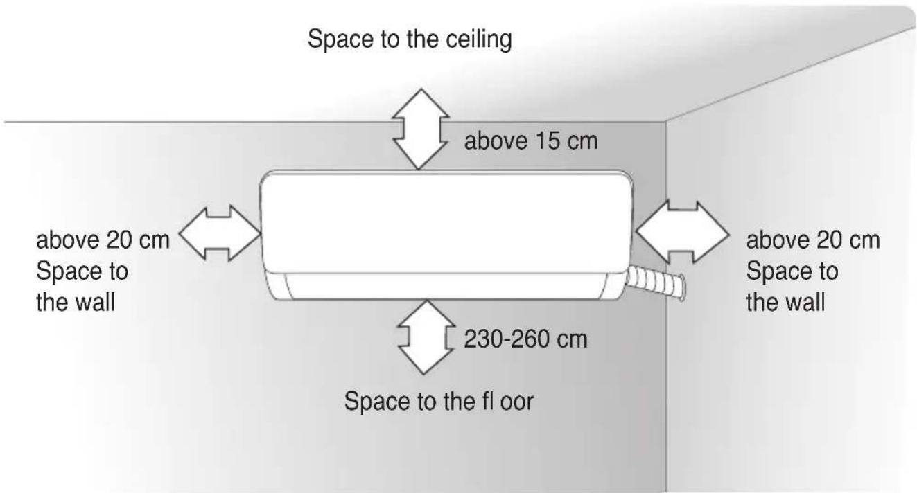
DIMENSION DRAWING OF INDOOR UNIT INSTALLATION
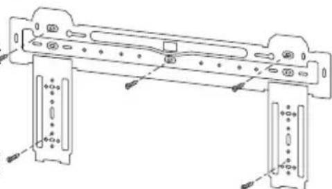
MOUNTING PLATE
-
The wall for installation of the indoor unit shall be hard and fi rm, so as to prevent vibration.
-
Use the «+» type screw to fasten the peg
natural_image
Technical line drawing of a mechanical bracket assembly (no text or symbols)board, horizontally mount the peg board on the wall, and ensure the lateral horizontal and longitudinal vertical.
- Pull the peg board by hand after the installation, to confirm whether it is solid.
WALL-THROUGH HOLE
-
Make a hole with an electric hammer or a water drill at the predetermined position on the wall for piping, which shall slant outwardly by 5^-10^ .
-
T o protect the piping and the cables from being damaged running through the wall, and from the rodents that may inhabit in the hollow wall, a pipe protecting ring shall be installed and sea
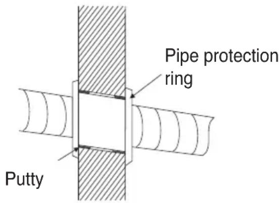
Note: Usually, the wall hole is 60mm80mm .
Avoid pre-buried power wire and hard wall when making the hole.
ROUTE OF PIPELINE
- Depending on the position of the unit, the piping may be routed sideways from the left or the right (Fig 1), or vertically from the back (Fig 2) (depending on the pipe length of the indoor unit). In the case of sideways routing, cut off the outlet cutting stock of the opposite side.
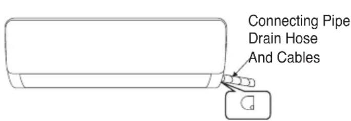
Fig.1 Fig.2
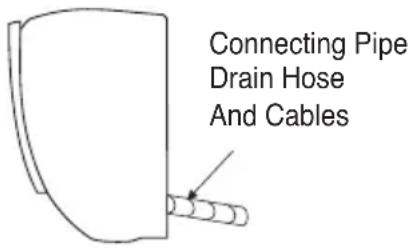
Outlet material preparation
DRAIN PIPE CONNECTION
- Remove the fixed part to pull out pipe of indoor machine from the case. Screw the hexagon nut in the left of the joint to the end with your hand.
- Connect the connecting pipe to the indoor unit:
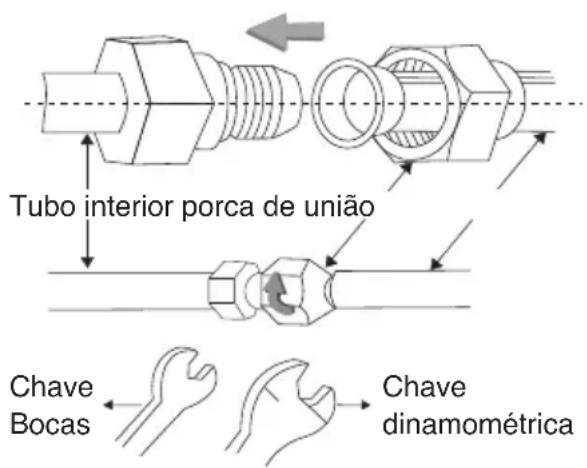
Aim at the pipe center, tighten the Taper nut with fingers, and then tighten the Taper nut with a torque wrench, and the direction is shown in diagram on the right. The torque used is shown in the following table.
Note: Carefully check if there is any damage of joints before installation. The joints shall not be reused, unless after re-fl aring the pipe.
Tightening torque table
| The size of pipe(mm) | Torque (N·m) |
| ∅ 6,35mm(1/4") 15~25 | |
| ∅ 9,52mm(3/8") 35~40 | |
| ∅ 12,7mm(1/2") 45~60 | |
| ∅ 15,88mm(5/8") 73~78 | |
| ∅ 19,05mm(3/4") 75~80 | |
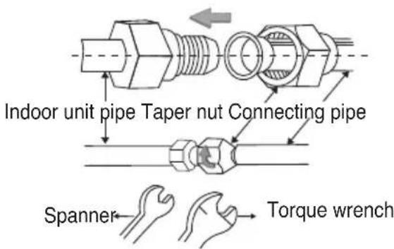
WRAP THE PIPING
-
Use the insulation sleeve to wrap the joint part the indoor unit and the connection pipe, and then insulating material to pack and seal insulation pipe, to prevent generation of condensate water on the joint part.
-
Connect the water outlet with drain pipes, and make the connection pipe, cables, and the drain hose straight.
-
Use plastic cable ties to wrap the connecting pipes, cables and drain hose. Run the pipe sloping downward.
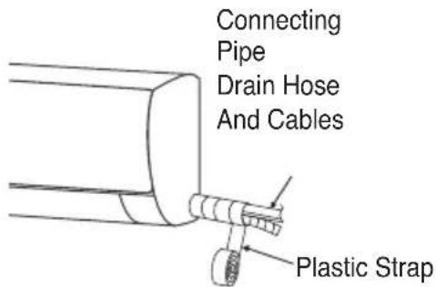
FIXING THE INDOOR UNIT
-
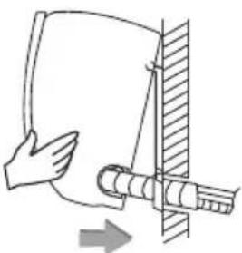
Hang the indoor unit on the peg board, and move the unit from left to right to ensure that the hook is properly positioned in the peg board.
-
Push toward the lower left side and the upper right side of the unit toward the
natural_image
Diagram of a hand holding a curved object with a cylindrical rod inserted, showing an arrow indicating direction (no text or symbols present)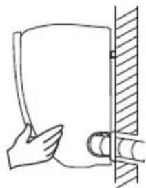
natural_image
Simple line drawing of a hand holding a document next to a vertical wall (no text or symbols)peg board, until the hook is embedded in the slot and makes a «click» sound.
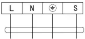
WIRING DIAGRAM
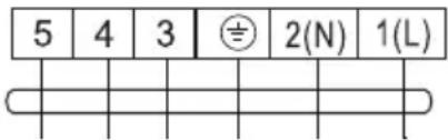
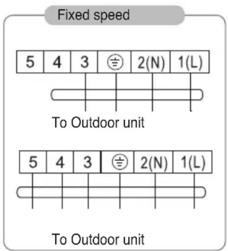
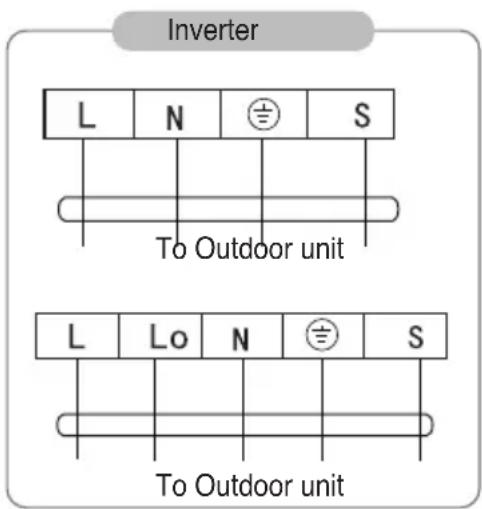
- If your air conditioner is provided with interconnection cord, the wiring of the indoor unit is connected in the factory, there is no need of connection.
• If the interconnection cord is not provided, connection is needed in accordance with the
After installation, check:
- the screws whether have been fixed effectively, and there is no risk of loosening.
- Connector of display board whether put in the right place and do not touch the terminal board.
- Control box cover whether cover tightly.
flowchart
graph TD
    subgraph Inverter
        A["L"] --> B["N"]
        C["S"] --> D["⊕"]
        E["To Outdoor unit"] --> F["To Outdoor unit"]
    end
    subgraph Outdoor Unit
        G["L"] --> H["Lo"]
        I["S"] --> J["N"]
        K["To Outdoor unit"] --> L["To Outdoor unit"]
    end
Connector
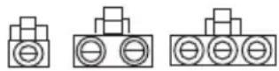
If there is a connector, connect it directly.
NOTE:
This manual usually includes the wiring mode for the different kind of A/C. We cannot exclude the possibility that some special type of wiring diagrams are not included.
- The diagram are for reference only. If the entity is difference with this wiring diagram, please refer to the detailed wiring diagram adhered on the unit which you purchased.
DIMENSION DRAWING OF OUTDOOR UNIT INSTALLATION
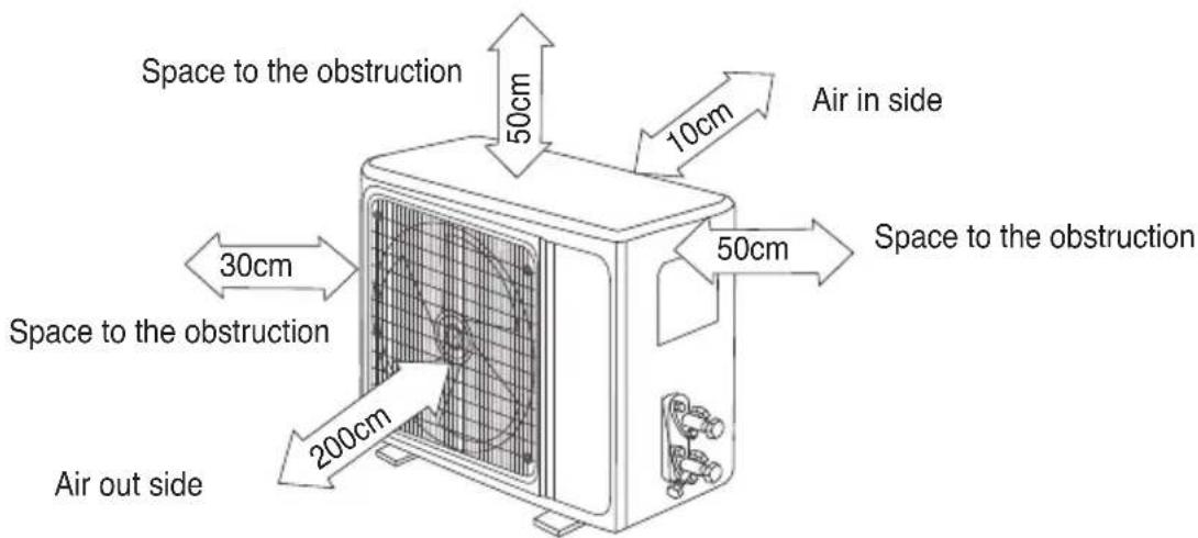
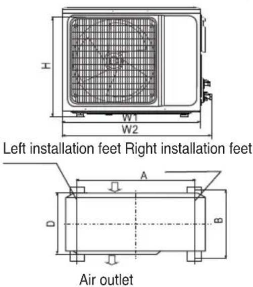
Installation outdoor unit bolt
| Outdoor Unit Size of Shape W1(W2)xHxD | A(mm) | B (mm) |
| 665(710)x420x280 430 | 280 | |
| 600(645)x485x260 400 | 290 | |
| 660(710)x500x240 500 | 260 | |
| 700(745)x500x255 460 | 260 | |
| 730(780)x545x285 540 | 280 | |
| 760(810)x545x285 540 | 280 | |
| 790(840)x550x290 545 | 300 | |
| 800(860)x545x315 545 | 315 | |
| 800(850)x590(690)x310 540 | 40 325 | |
| 825(880)x655x310 540 | 335 | |
| 900(950)x700x350 630 | 350 | |
| 900(950)x795x330 535 | 350 | |
| 970(1044)x803x395 675 | 409 |
INSTALL THE CONNECTION PIPE
Connect the Outdoor Unit with Connecting Pipe: Aim the counter-bore of the connecting pipe at the stop valve, and tighten the Taper nut with fingers. Then tighten the Taper nut with a torque wrench.
- When prolonging the piping, extra amount of refrigerant must be added so that the operation and performance of the air conditioner will not be compromised.
| Piping length Amount of refrigerant to be added | Amount of refrigerator for the unit | ||
| ≤5m Not needed | |||
| 5-15m | CC≤12000Btu/h | 16g/m ≤1kg | |
| CC≤18000Btu/h | 24g/m ≤2kg | ||
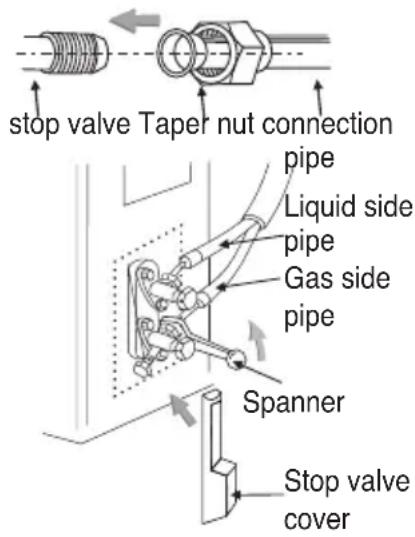
Note:
- This table is for reference only
- The joints shall not be reused, unless after re-fl aring the pipe.
- After installation, check the stop valve cover whether be fixed effectively.
WIRING CONNECTION
-
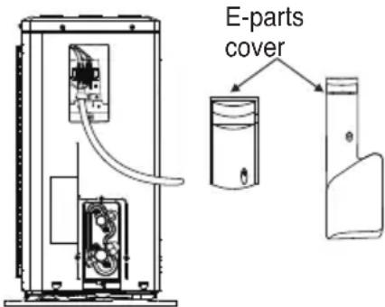
Loosen the screws and remove E-parts cover from the unit.
-
Connect the cables respectively to the corresponding terminals of the terminal board of the outdoor unit (see the wiring diagram), and if there are signals connected to the plug, just conduct butt joint.
-
Ground wire: Remove the grounding screw out of the electric bracket, cover the grounding wire end onto the grounding screw and screw it into the grounding hole.
-
Fix the cable reliably with fasteners (Pressing board).
-
Put the E-parts cover back in its original place and fasten it with screws.
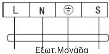
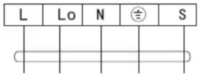
WIRING DIAGRAM
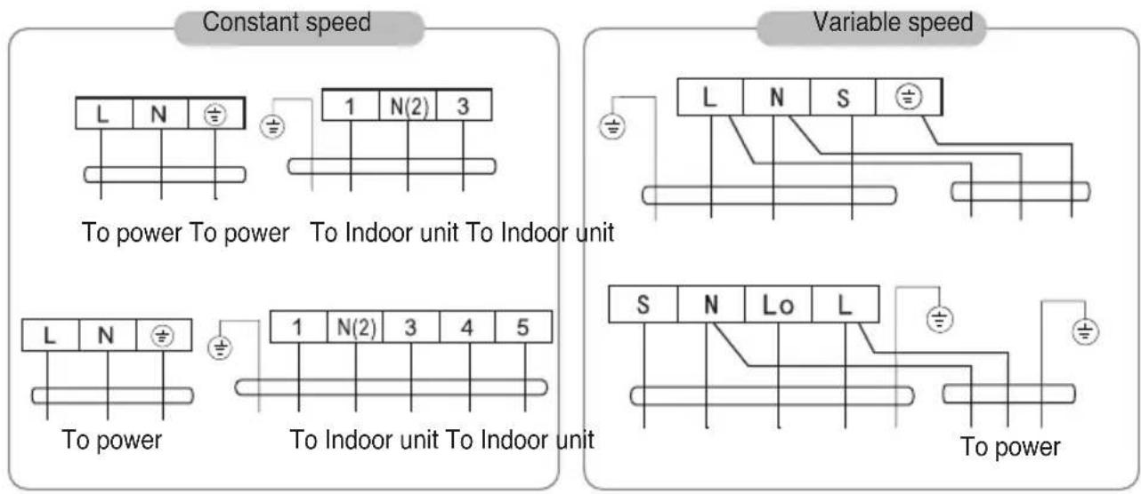
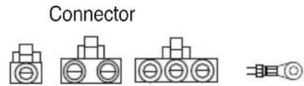
If there is a connector, connect it directly.
NOTE:
- This manual usually includes the wiring mode for the different kind of A/C. We cannot exclude the possibility that some special type of wiring diagrams are not included.
- The diagram are for reference only. If the entity is difference with this wiring diagram, please refer to the detailed wiring diagram adhered on the unit which you purchased.
VACUUMING
*Exclusive R32 refrigerant pump must be used in making R32 refrigerant vacuum. Before working on the air conditioner, remove the cover of the stop valve(gas and liquid valves) and be sure to retighten it afterward. (to prevent the potential air leakage)
- To prevent air leakage and spilling tighten all connecting nut of all fl are tubes.
- Connect the stop valve, charge hose, manifold valve, and vacuum pump.
- Fully open the handle Lo of the manifold valve and apply vacuum for at least 15
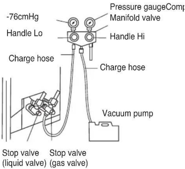
minutes and check that the compound vacuum gauge reads -0.1 MPa(-76cmHg).
- After applying vacuum, fully open the stop valve with a hex wrench.
- Check that both indoor and outdoor connections are free of air leakage.
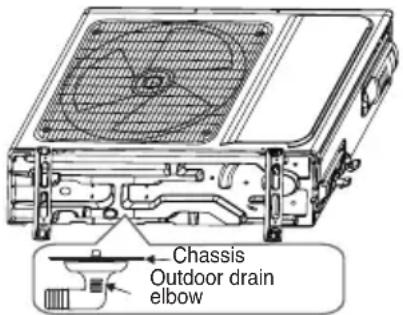
OUTDOOR CONDENSATION DRAINAGE (HEAT PUMP TYPE ONLY)
When the unit is heating, the condensing water and defrosting water can be out reliably through the drain house.
Installation:
Install the outdoor drain elbow in 25 hole on the base plate, and joint the drain hose to the elbow, so that the waste water formed in the outdoor unit can be drained out to a proper plate.
CHECK AFTER INSTALLATION AND TEST OPERATION
CHECK AFTER INSTALLATION
• Electrical Safety Check
- If the supply voltage is as required.
- If there is any faulty or miss connection in each of the power, signal and grounding wires.
- If the grounding wire of the air conditioner is securely grounded.
• Installation Safety Check
- If the installation is secure.
- If the water drain is smooth.
- If the wiring and piping are correctly installed.
- Check that no foreign matter or tools are left inside the unit.
- Check the refrigerant pipeline is protected wel.
- Leak test of the refrigerant
Depending on the installation method, the following methods may be used to check for suspect leak, on areas such as the four connections of the outdoor unit and the cores of the cut-off valves and t-valves:
- Bubble method: Apply of spray a uniform layer of soap water over the suspected leak spot and observe carefully for bubble.
- Instrument method: Checking for leak by pointing the probe of the leak detector according to the instruction to the suspect points of leak.
Note: Make sure that the ventilation is good before checking.
TEST OPERATION
Test Operation preparation:
- Verify that all piping and connection cables are well connected.
- Confirm that the values at the gas side the liquid-side are fully open.
- Connect the power cord to an independet power socket.
• Install batteries in remote control.
Note: Make sure that the ventilation is good before testing.
Test Operation method:
- Turn on the power and push the ON/OFF switch button of the remote controller to start the air conditioner.
- Select COOL, HEAT (not available on cool-only models), SWING and other operation modes with the remote controller and see if the operation is ok.
MAINTENANCE NOTICE
Attention:
For maintenance or scrap, please contact authorized service centers.
Maintenance by unqualifi ed person may cause dangers.
Feed air conditioner with R32 refrigerant, and maintain the air conditioner in strictly accordance with manufacturer's requirements. The chapter is mainly focused on special maintenance requirements for appliance with R32 refrigerant. Ask repairer to read after-sales technical service handbook for detailed information.
QUALIFICATION REQUIREMENTS OF MAINTENANCE PERSONNEL
-
Special training additional to usual refrigerating equipment repair procedures is required when equipment with flammable refrigerants is affected. In many countries, this training is carried out by national training organisations that are accredited to teach the relevant national competency standards that may be set in legislation. The achieved competence should be documented by a certifi cate.
-
The maintenance and repair of the air conditioner must be conducted according to the method recommended by the manufacturer. If other professionals are needed to help maintain and repair the equipment, it should be conducted under the supervision of individuals who have the qualification to repair AC equipped with flammable refrigerant.
INSPECTION OF THE SITE
Safety inspection must be taken before maintaining equipment with R32 refrigerant to make sure the risk of fire is minimized. Check whether the place is well ventilated, whether anti-static and fire prevention equipment is perfect. While maintaining the refrigeration system, observe the following precautions before operating the system.
OPERATING PROCEDURES
1. General work area:
All maintenance staff and others working in the local area shall be instructed on the nature of work being carried out. Work in confined spaces shall be avoided. The area around the workspace shall be sectioned off. Ensure that the conditions within the area have been made safe by control of flammable material.
2. Checking for presence of refrigerant:
The area shall be checked with an appropriate refrigerant detector prior to and during work, to ensure the technician is aware of potentially toxic or flammable atmospheres. Ensure that the leak detection equipment being used is suitable for use with all applicable refrigerants, i.e. non-sparking, adequately sealed or intrinsically safe.
3. Presence of fire extinguisher:
If any hot work is to be conducted on the refrigeration equipment or any associated parts, appropriate fire extinguishing equipment shall be available to hand. Have a dry powder or CO_2 fire extinguisher adjacent to the charging area.
4. No ignition sources:
No person carrying out work in relation to a refrigeration system which involves exposing any pipe work shall use any sources of ignition in such a manner that it may lead to the risk of fire or explosion. All possible ignition sources, including cigarette smoking, should be kept sufficiently far away from the site of installation, repairing, removing and disposal, during which refrigerant can possibly be released to the surrounding space. Prior to work taking place, the area around the equipment is to be surveyed to make sure that there are no fl ammable hazards or ignition risks.
'No Smoking' signs shall be displayed.
5. Ventilated Area(open the door and window):
Ensure that the area is in the open or that it is adequately ventilated before breaking into the system or conducting any hot work. A degree of ventilation shall continue during the period that the work is carried out. The ventilation
should safely disperse any released refrigerant and preferably expel it externally into the atmosphere.
6. Checks to the refrigeration equipment:
Where electrical components are being changed, they shall be fit for the purpose and to the correct specification. At all times the manufacturer's maintenance and service guidelines shall be followed. If in doubt, consult the manufacturer's technical department for assistance. The following checks shall be applied to installations using fl ammable refrigerants:
- The charge size is in accordance with the room size within which the refrigerant containing parts are installed.
- The ventilation machinery and outlets are operating adequately and are not obstructed.
• If an indirect refrigerating circuit is being used, the secondary circuit shall be checked for the presence of refrigerant. - Refrigeration pipe or components are installed in a position where they are unlikely to be exposed to any substance which may corrode refrigerant containing components, unless the components are constructed of materials which are inherently resistant to being corroded or are suitably protected against being so corroded.
7. Checks to electrical devices:
Repair and maintenance to electrical components shall include initial safety checks and component inspection procedures. If a fault exists that could compromise safety, then no electrical supply shall be connected to the circuit until it is satisfactorily dealt with. If the fault cannot be corrected immediately but it is necessary to continue operation, an adequate temporary solution shall be used. This shall be reported to the owner of the equipment so all parties are advised.
Initial safety checks shall include:
- That capacitors are discharged: this shall be done in a safe manner to avoid possibility of sparking.
- That no live electrical components and wiring are exposed while charging, recovering or purging the system.
- Keep continuity of earthing.
INSPECTION OF CABLE
Check the cable for wear, corrosion, overvoltage, vibration and check if there are sharp edges and other adverse effects in the surrounding environment. During the inspection, the impact of aging or the continuous vibration of the compressor and the fan on it should be taken into consideration.
LEAKAGE CHECK OF R32 REFRIGERANT
Note: Check the leakage of the refrigerant in an environment where there is no potential ignition source. No halogen probe (or any other detector that uses an open flame) should be used.
Leak detection method:
For systems with refrigerant R32, electronic leak detection instrument is available to detect and leak detection should not be conducted in environment with refrigerant. Make sure the leak detector will not become a potential source of ignition, and is applicable to the measured refrigerant. Leak detector shall be set for the minimum ignitable fuel concentration (percentage) of the refrigerant. Calibrate and adjust to proper gas concentration (no more than 25%) with the used refrigerant. The fluid used in leak detection is applicable to most refrigerants. But do not use chloride solvents to prevent the reaction between chlorine and refrigerants and the corrosion of copper pipeline. If you suspect a leak, then remove all the fire from the scene or put out the fire.
If the location of the leak needs to be welded, then all refrigerants need to be recovered, or, isolate all refrigerants away from the leak site (using cut-off valve). Before and during the welding, use OFF to purify the entire system.
REMOVAL AND VACUUM PUMPING
- Make sure there is no ignited fire source near the outlet of the vacuum pump and the ventilation is well.
-
Allow the maintenance and other operations of the refrigeration circuit should be carried out according to the general procedure, but the following best operations that the flammability is already taken into consideration are the key. You should follow the following procedures:
-
Remove the refrigerant.
- Decontaminate the pipeline by inert gases.
- Evacuation.
- Decontaminate the pipeline by inert gases again.
-
Cut or weld the pipeline.
-
The refrigerant should be returned to the appropriate storage tank. The system should be blown with oxygen free nitrogen to ensure safety. This process may need to be repeated for several times. This operation shall not be carried out using compressed air or oxygen.
-
Through blowing process, the system is charged into the anaerobic nitrogen to reach the working pressure under the vacuum state, then the oxygen free nitrogen is emitted to the atmosphere, and in the end, vacuumize the system. Repeat this process until all refrigerants in the system is cleared.
After the final charging of the anaerobic nitrogen, discharge the gas into the atmosphere pressure, and then the system can be welded. This operation is necessary for welding the pipeline.
PROCEDURES OF CHARGING REFRIGERANTS
As a supplement to the general procedure, the following requirements need to be added:
• Make sure that there is no contamination among different refrigerants when using a refrigerant charging device. The pipeline for charging refrigerants should be as short as possible to reduce the residual of refrigerants in it.
- Storage tanks should remain vertically up.
• Make sure the grounding solutions are already taken before the refrigeration system is charged with refrigerants.
• After finishing the charging (or when it is not yet finished), label the mark on the system.
- Be careful not to overcharge refrigerants.
SCRAP AND RECOVERY
Scrap:
Before this procedure, the technical personnel shall be thoroughly familiar with the equipment and all its features, and make a recommended practice for refrigerant safe recovery. For recycling the refrigerant, shall analyze the refrigerant and oil samples before operation.
Ensure the required power before the test.
- Be familiar with the equipment and operation.
- Disconnect power supply.
- Before carrying out this process, you have to make sure:
• If necessary, mechanical equipment operation should facilitate the operation of the refrigerant tank.
• All personal protective equipment is effective and can be used correctly.
- The whole recovery process should be carried out under the guidance of qualified personnel.
• The recovering of equipment and storage tank should comply with the relevant national standards.
- If possible, the refrigerating system should be vacuumized.
- If the vacuum state can't be reached, you should extract the refrigerant in each part of the system from many places.
- Before the start of the recovery, you should ensure that the capacity of the
storage tank is sufficient.
- Start and operate the recovery equipment according to the manufacturer's instructions.
- Don't fill the tank to its full capacity (the liquid injection volume does not exceed 80% of the tank volume).
- Even the duration is short, it must not exceed the maximum working pressure of the tank.
- After the completion of the tank filling and the end of the operation process, you should make sure that the tanks and equipment should be removed quickly and all closing valves in the equipment are closed.
- The recovered refrigerants are not allowed to be injected into another system before being purified and tested.
Note: The identification should be made after the appliance is scrapped and refrigerants are evacuated. The identification should contain the date and endorsement. Make sure the identification on the appliance can reflect the fl ammable refrigerants contained in this appliance.
Recovery:
- The clearance of refrigerants in the system is required when repairing or scrapping the appliance. It is recommended to completely remove the refrigerant.
- Only a special refrigerant tank can be used when loading the refrigerant into the storage tank. Make sure the capacity of the tank is appropriate to the refrigerant injection quantity in the entire system. All tanks intended to be used for the recovery of refrigerants should have a refrigerant identification (i.e. refrigerant recovery tank). Storage tanks should be equipped with pressure relief valves and globe valves and they should be in a good condition. If possible, empty tanks should be evacuated and maintained at room temperature before use.
- The recovery equipment should be kept in a good working condition and equipped with equipment operating instructions for easy access. The equipment should be suitable for the recovery of R32 refrigerants. Besides, there should be a qualified weighting apparatus which can be normally used. The hose should be linked with detachable connection joint of zero leakage rate and be kept in a good condition.
Before using the recovery equipment, check if it is in a good condition and if it gets perfect maintenance. Check if all electrical components are sealed to prevent the leakage of the refrigerant and the fire caused by it. If you have any question, please consult the manufacturer.
- The recovered refrigerant shall be loaded in the appropriate storage tanks, attached with a transporting instruction, and returned to the refrigerant manufacturer. Don't mix refrigerant in recovery equipment, especially a storage tank.
- The space loading R32 refrigeration can't be enclosed in the process of transportation. Take anti electrostatic measures if necessary in transportation. In the process of transport, loading and unloading, necessary protective measures must be taken to protect the air conditioner to ensure that the air conditioner is not damaged.
- When removing the compressor or clearing the compressor oil, make sure the compressor is pumped to an appropriate level to ensure that there is no residual R32 refrigerants in the lubricating oil. The vacuum pumping should be carried out before the compressor is returned to the supplier. Ensure the safety when discharging oil from the system.
natural_image
Simple line drawing of a cylindrical object with a handle and internal slots (no text or symbols)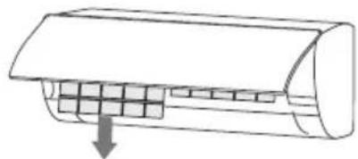
natural_image
Diagram of a car air conditioner unit with cooling fins and airflow direction arrow (no text or labels)natural_image
Illustration showing a car being cleaned on a grid surface next to a washing bottle and bowl (no text or symbols)natural_image
Diagram of a car air conditioner unit with internal cooling fins and airflow direction arrow (no text or labels)
ATTENZIONE
Press this button to activate your air conditioner. Press it again to deactivate it.
2. PULSANTE MODE
natural_image
Technical line drawing of a mechanical bracket assembly (no text or symbols)natural_image
Two-step diagram showing hands holding a cylindrical object with a ruler, connected by a tool to a wall (no text or symbols)SCHEMA ELETTRICO
natural_image
Line drawing of a cylindrical object with a handle and internal slots, no text or symbols present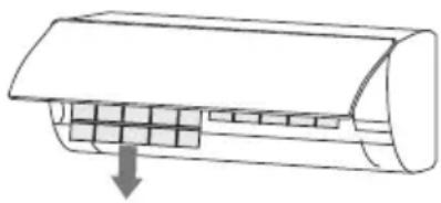
natural_image
Diagram of a car air conditioner unit with cooling fins and airflow direction arrow (no text or symbols)natural_image
Illustration showing a car being cleaned on a grid surface next to a bowl of laundry (no text or symbols)natural_image
Diagram of a car air conditioner unit with internal compartments and airflow direction arrow (no text or labels)
ATENCION
natural_image
Technical line drawing of a mechanical assembly with mounting brackets and fasteners (no text or symbols)AGUJERO PASANTE EN LA PARED
natural_image
Diagram of a hand holding a curved object with a cylindrical component inserted, showing an arrow indicating direction (no text or symbols present)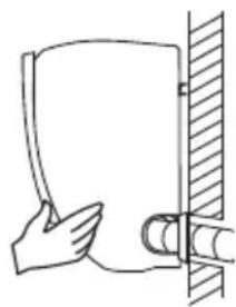
natural_image
Simple line drawing of a hand holding a document next to a vertical wall (no text or symbols)natural_image
Technical line drawing of a mechanical or electrical enclosure with internal components and wiring (no text or symbols)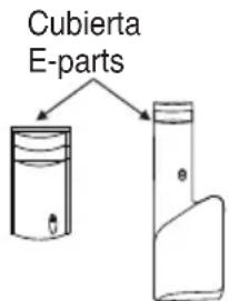
A potencia
Conector

Si dispone de conector, conéctelo directamente.
NOTA:
natural_image
Line drawing of hands installing or adjusting a wall-mounted air conditioner (no text or symbols)natural_image
Simple line drawing of a cylindrical object with a handle and internal structure (no text or symbols)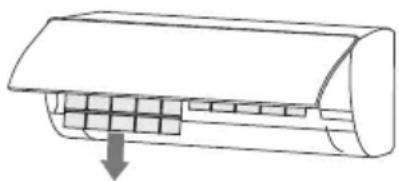
natural_image
Diagram of a car air conditioner unit with cooling fins and airflow direction arrow (no text or labels)natural_image
Illustration showing a hand using a vacuum cleaner to clean a grid-patterned surface next to a bowl of laundry (no text or symbols)natural_image
Diagram of a car air conditioner unit with cooling fins and airflow direction arrow (no text or labels)ATENÇÃO
natural_image
Simple line drawing of a rectangular object with an arrow indicating direction, enclosed in a circle (no text or symbols)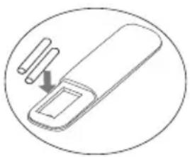
natural_image
Simple line drawing of a pen-like object with a handle and two cylindrical pins, enclosed in a circle (no text or symbols)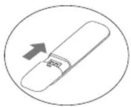
natural_image
Simple line drawing of a rolled-up document or scroll with an arrow indicating upward motion (no text or symbols)natural_image
Technical line drawing of a mechanical support frame with mounting holes and mounting brackets (no text or symbols)ATRAVÉS DE UM ORIFICIO NA PAREDE
| Tamanho do tubo (mm) | Por (N-in) |
| ∅ 6.35mm (1/4") | 15~25 |
| ∅ 9.52mm (3/8") | 35~40 |
| ∅ 12,7mm (1/2") | 45~60 |
| ∅ 15.88mm (5/8") | 73~78 |
| ∅ 19.05mm (3/4") | 75~80 |
natural_image
Two-step diagram showing hand positioning of a mechanical component between two vertical surfaces, with an arrow indicating direction (no text or symbols)DIAGRAMA DE CABLAGEM
natural_image
Technical line drawing of a device interior with internal components and wiring (no text or symbols)flowchart
graph TD
    A["Component 1"] --> B["Component 2"]
DIAGRAMA DE CABLAGEM
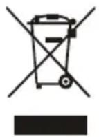
This marking indicates that this product should not be disposed with other household wastes throughout the EU. To prevent possible harm to the environment or human health from uncontrolled waste disposal, please recycle it responsibly to promote the sustainable reuse of material resources. By ensuring proper product disposal, you help prevent potential negative environmental and health impacts. Recycling materials will help save natural resources. To dispose/return your used device please follow the return and collection systems of your country or contact the retailer from where you purchased this product. This product must be sent for environmental safe recycling.
Certifi cate of compliance CE
TOYOTOMI CO., LTD declares that this product complies with the general requirements pursuant to the following European Directives:
LVD: 2014/35/EU
EMC: 2014/30/EU
RoHS: (EU)2015/863
ERP: 2011/65/EU
RED: 2014/53/EU
WiFi: Wireless maximum transmit power: 802.11b:16dBm / 802.11g:14dBm / 802.11n:13dBm
Wireless frequency range: 2.412 GHz - 2.484 GHz
Therefore the product has been marked with the CE symbol and the Declaration of Conformity has been issued and is available to the competent authorities regulating the market.
It is prohibited to reprint or reproduction of all or part of this manual in any manner without written permission of TOYOTOMI CO., LTD
This product is made in China
- ΠΡΟΣΟΧΗ
- THE REFRIGERANT
- WARNING
- PRECAUTIONS
- Operation and Maintenance
- This product contains fl uorinated greenhouse gases
- USEFUL TIPS
- Conditions where the Air Conditioner might not run normally
- NOTES FOR HEATING
- NOTES FOR TURNING OFF THE AIR CONDITIONER
- EMERGENCY OPERATION
- ADJUSTMENT OF AIR FLOW DIRECTION
- PAY ATTENTION
- CLEAN AND MAINTENANCE
- CLEANING THE INDOOR UNIT
- CLEANING THE AIR FILTERS
- ATTENTION
- CHECK BEFORE USE
- MAINTENANCE
- IMPORTANT NOTICE FOR PROPER RECYCLING
- TROUBLESHOOTING
- CAUTION
- PART DESCRIPTION
- BUTTONS DESCRIPTION
- INSTRUCTIONS FOR PROPER USE OF THE REMOTE CONTROLLER
- Note:
- BUTTON DESCRIPTION
- BUTTON ON/OFF
- BUTTON MODE
- BUTTON TIMER
- BUTTON HEAT
- BUTTON COOL
- BUTTON SPEED
- BUTTONS “+” or “-”
- BUTTON MENU/OK
- BUTTON L/R SWING
- BUTTON U/D SWING
- HEALTH FUNCTION
- ECO FUNCTION
- SLEEP FUNCTION
- SILENCE FUNCTION
- ELE-H FUNCTION (This function is not available)
- DISPLAY FUNCTION
- LIGHT FUNTION
- I-FEEL FUNCTION
- ANTI-F FUNCTION (Auto Clean):
- iCLEAN FUNCTION (Sterilization 56°C)
- CHILD-LOCK FUNCTION
- 8°C Heating function
- USAGE FOR MODE
- Auto Operation mode
- Cool/Heat operation Mode
- Fan operation Mode
- Dry Operation mode
- Insert Batteries to remote controller
- NOTICES FOR INSTALLATION
- IMPORTANT NOTICES
- UNPACKING INSPECTION
- SAFETY PRINCIPLES FOR INSTALLING AIR CONDITIONER
- REQUIREMENTS FOR INSTALLATION POSITION
- INSTALLATION ENVIRONMENT INSPECTION
- REQUIREMENTS OF THE MOUNTING STRUCTURE
- ELECTRICAL SAFETY REQUIREMENTS
- REQUIREMENTS FOR OPERATIONS AT RAISED HEIGHT
- GROUNDING REQUIREMENTS
- OTHERS
- PACKING LIST
- INSTALL INDOOR UNIT
- MOUNTING PLATE
- WALL-THROUGH HOLE
- ROUTE OF PIPELINE
- DRAIN PIPE CONNECTION
- WRAP THE PIPING
- FIXING THE INDOOR UNIT
- WIRING DIAGRAM
- INSTALL THE CONNECTION PIPE
- WIRING CONNECTION
- VACUUMING
- OUTDOOR CONDENSATION DRAINAGE (HEAT PUMP TYPE ONLY)
- CHECK AFTER INSTALLATION AND TEST OPERATION
- CHECK AFTER INSTALLATION
- • Electrical Safety Check
- • Installation Safety Check
- - Leak test of the refrigerant
- TEST OPERATION
- Test Operation preparation:
- Test Operation method:
- MAINTENANCE NOTICE
- Attention:
- QUALIFICATION REQUIREMENTS OF MAINTENANCE PERSONNEL
- INSPECTION OF THE SITE
- OPERATING PROCEDURES
- General work area:
- Checking for presence of refrigerant:
- Presence of fire extinguisher:
- No ignition sources:
- Ventilated Area(open the door and window):
- Checks to the refrigeration equipment:
- Checks to electrical devices:
- INSPECTION OF CABLE
- LEAKAGE CHECK OF R32 REFRIGERANT
- REMOVAL AND VACUUM PUMPING
- PROCEDURES OF CHARGING REFRIGERANTS
- SCRAP AND RECOVERY
- Scrap:
- Recovery:
- ATTENZIONE
- PULSANTE MODE
- SCHEMA ELETTRICO
- ATENCION
- AGUJERO PASANTE EN LA PARED
- NOTA:
- ATENÇÃO
- ATRAVÉS DE UM ORIFICIO NA PAREDE
- DIAGRAMA DE CABLAGEM
- Certifi cate of compliance CE
Brand : Toyotomi
Model : THN/THG-A56SZ
Category : Air conditioner