
SPLIT-3726MF - Air conditioner Infiniton - Free user manual and instructions
Find the device manual for free SPLIT-3726MF Infiniton in PDF.


| Product Type | Split Air Conditioner (Wall-Mounted Indoor Unit + Outdoor Unit) |
| Model | SPLIT-3726MF |
| Brand | Infiniton |
| Indoor Unit Dimensions (HxWxD) | ~270 x 800 x 200 mm (approx, varies by model) |
| Outdoor Unit Dimensions (HxWxD) | 434 x 681 x 285 mm (typical for this series) |
| Power Supply | 220-240 V ~ 50 Hz |
| Refrigerant Type | R32 |
| Cooling Capacity | ~3.5 kW (12,000 Btu/h) approx. |
| Heating Capacity | ~3.8 kW (13,000 Btu/h) approx. |
| Energy Efficiency (SEER) | ≥ 5.1 (A+++ or A++ depending on model) |
| Operating Modes | Auto, Cool, Heat, Dry, Fan |
| Special Functions | Sleep Mode, iClean Self-Cleaning, Health Ionizer, Wi-Fi Ready, Timer, Anti-F, 8°C Heating |
| Fan Speeds | Low, Mid, High, Auto |
| Airflow Direction | Vertical & Horizontal Louvers (Remote Controlled) |
| Filter Type | Washable Pre-Filter + Optional Plasma Air Purifier Filter |
| Remote Control | Included (Universal LCD Display) |
| Noise Level (Indoor) | ~25 - 40 dB(A) (approx, varies by speed) |
| Noise Level (Outdoor) | ~50 - 55 dB(A) (approx) |
| Refrigerant Pipe Length (Max) | 25 m (for capacities <15,000 Btu/h) |
| Max. Height Difference | 10 m (for capacities <15,000 Btu/h) |
| Compressor Type | Inverter (variable speed) for most models |
| Installation Requirements | Professional installation by certified F-Gas technician required |
Frequently Asked Questions - SPLIT-3726MF Infiniton
User questions about SPLIT-3726MF Infiniton
0 question about this device. Answer the ones you know or ask your own.
Ask a new question about this device
Download the instructions for your Air conditioner in PDF format for free! Find your manual SPLIT-3726MF - Infiniton and take your electronic device back in hand. On this page are published all the documents necessary for the use of your device. SPLIT-3726MF by Infiniton.
USER MANUAL SPLIT-3726MF Infiniton
natural_image
Illustration of a worker installing or adjusting an air conditioner on a lift (no text or symbols present)
natural_image
Illustration of a worker in a hard hat installing or adjusting an air conditioner panel on a metal frame (no text or symbols visible)natural_image
Illustration of three workers installing or maintaining a large air conditioner unit, surrounded by greenery and tools (no text or symbols)Índice
Español
natural_image
Symbol of a trash bin with crossed lines indicating no waste, and a solid rectangle below (no text or labels)natural_image
Technical diagram of a mechanical assembly with labeled components and motion indicators (no readable text or symbols)natural_image
Mechanical diagram showing a tool interacting with a bolt and valve (no text or symbols present)Conecte la tubería
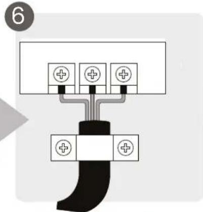
Conecte el cableado
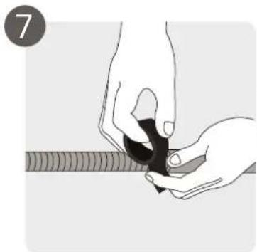
natural_image
Illustration of hands holding a black object over a wavy line (no text or symbols)natural_image
Diagram showing cable installation with a coiled cable and exposed wires (no text or symbols)natural_image
Illustration of two hands holding a horizontal bar with upward arrows, no text or symbols present(1)
(2)
natural_image
Technical line drawing of a rectangular electronic component or enclosure with internal compartments (no text or symbols)natural_image
Pure electrical circuit lines without any symbolsTipo A
natural_image
Pure mechanical linkage diagram showing two vertical components connected by a horizontal bar (no text or symbols)T
ipo B
Modelo B
Modelo C
natural_image
Technical line drawing of a mechanical device with spring and lever components (no text or symbols)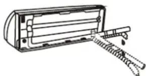
natural_image
Line drawing of a mechanical device with a spring and handle (no text or symbols)
PRECAUCIÓN
natural_image
Technical line drawing of a mechanical fan or air conditioning unit with dimension labels H and W (no text or symbols on the diagram itself)| Dimensiones de la unidad exterior en mm. Alto x Ancho x Profundo | Dimensiones de montaje | |
| Distancia A (mm) | Distancia B (mm) | |
| 434x681x285 460 292 | ||
| 550x700x270 450 260 | ||
| 550x700x275 450 260 | ||
| 495x720x270 452 255 | ||
| 555x728x300 452 302 | ||
| 555x765x303 452 286 | ||
| 555x770x300 487 298 | ||
| 554x805x330 511 317 | ||
| 554x800x333 514 340 | ||
| 702x845x363 540 350 | ||
| 673x890x342 663 354 | ||
| 810x946x420 673 403 | ||
| 810x946x410 673 403 | ||
natural_image
3D mechanical component diagram with no visible text or symbolsnatural_image
Close-up of an electrical terminal block with labeled terminals (L, L0, N, S) and wiring, no readable text or symbols beyond component labels.Unidad exterior
natural_image
Electrical wiring and components inside a circuit board (no readable text or symbols)natural_image
Line drawing of hands using a tool to lift a mechanical component (no text or symbols)natural_image
Line drawing of a small air conditioner unit with fan and control panel (no text or symbols)Tapa de válvula
natural_image
Illustration of hands using a tool to adjust or install a mechanical component (no text or symbols visible)Evacuación de aire
natural_image
Simple line drawing of a remote control device inside a circle (no text or symbols)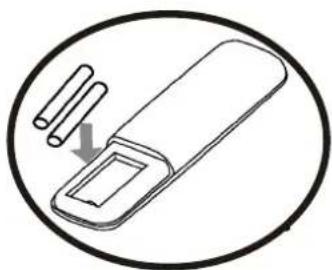
natural_image
Simple line drawing of a device with two cylindrical pins and an arrow indicating direction (no text or symbols)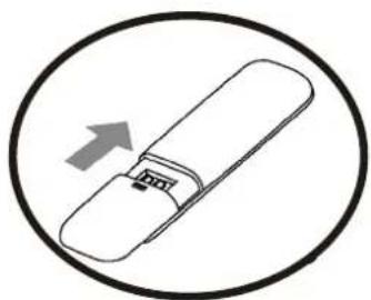
natural_image
Simple line drawing of a USB flash drive inside a circle (no text or symbols)1. ON/OFF
Low -> Mid -> High -> Auto
natural_image
Diagram of a hand pressing down on a textured panel with a black arrow symbol (no text or labels)
natural_image
Diagram showing a faucet above a grid-patterned panel with a central arrow (no text or symbols)natural_image
Diagram of a grid-patterned rectangular block with an arrow indicating force or direction (no text or symbols)
natural_image
Simple line drawing of a house with wavy lines inside, no text or symbols presentnatural_image
Line drawing of a smartphone with internal components (no text or symbols)Air conditioner type Split Section FIT Series CRUSH
natural_image
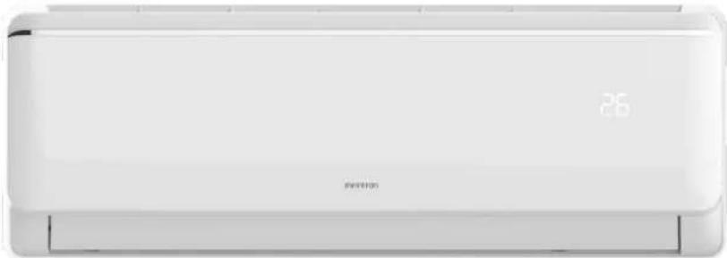
Front view of a white air conditioner unit with a digital display showing '25' and '26' (no text or symbols on the device itself)Model: SPTMF12A2
ean: 8445639001028
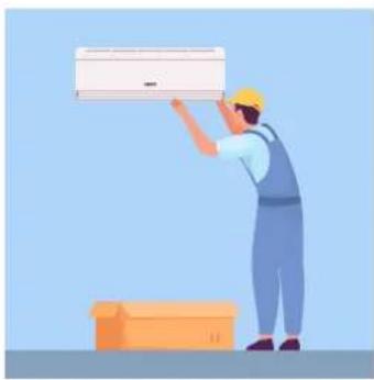
Your air conditioning, installed only by professionals
Equipment containing fluorinated gases, such as air conditioners, can only be installed by a professional who is certified to handle this type of gas and who works in an authorised installation company, according to the regulations in force since 2017. In addition, as a buyer, you also have your obligations and possible fines if you fail to comply with them.
natural_image
Illustration of a worker installing or adjusting an air conditioner on a lift (no text or symbols present)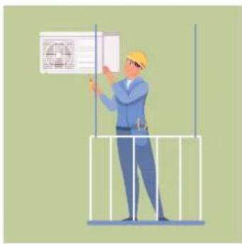
natural_image
Illustration of a worker in a hard hat installing or adjusting an air conditioner unit on a metal frame (no text or symbols visible)Installation requirements
The sale and handling of equipment containing fluorinated gases that is not hermetically sealed (as is the case of current air conditioning, refrigeration and heat pump systems) is regulated by a 2017 decree (RD 115/2017), which establishes installation requirements and some obligations for the purchaser.
Dual certification for highly polluting appliances
According to the law, this equipment can only be installed by a professional who holds a certificate for handling fluorinated gases and who works in an installation company authorised to install equipment with this type of gas. In other words, a double certification is required:
- As a certified professional for the handling of fluorinated gases.
• As a company authorised for fluorinated gases. - The need to have professionals duly trained and certified in the handling of these systems is mainly due to the fact that they are highly polluting elements.
Infiniton guarantees the professionalism of each and every one of our installers.
The need to have professionals duly trained and certified in the handling of these systems is mainly due to the fact that they are highly polluting elements.
On the website of the Ministry of Industry you can consult the companies that already have F-Gas certification.
The buyer must send the seller, within a maximum period of one year, Annex VI, part B of the 2017 decree (RD 115/2017) signed by him and the installer who has carried out the installation, including the details of the equipment and the certificates of the installer and the authorised company.
natural_image
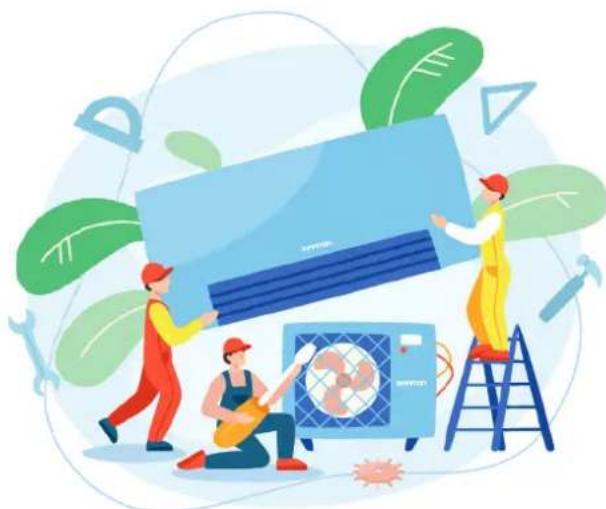
Illustration of three workers installing or maintaining a large blue air conditioner unit, surrounded by greenery and tools (no text or symbols)| Index | English |
| Safety warnings | 54 |
| Instructions before use | 56 |
| Installation | 60 |
| Specifications and features of the unit | 81 |
| Operation | 85 |
| Troubleshooting | 89 |
| Cleaning and maintenance | 91 |
An air conditioner is a basic in every home, its features are countless, only that, in addition to those you already know, now also protect your home from viruses, bacteria, smoke and allergens.
What do Infiniton air conditioning filters do to protect you?
Improving the air quality in your home is an obsession for Infiniton's R&D department. Your well-being and that of those around you is important to us. We've created filters that capture smoke, pollen, viruses and bacteria and other allergens and remove them. It's as simple as that, but let us explain the process a little, it's not magic, it's technology!
How it works means that our air conditioning systems are able to neutralise harmful particles to improve the quality of the air you breathe. A process that is carried out by the air conditioner while you watch TV, have dinner or chat with your family. At Infiniton we have declared war against
HUMO

ALÉRGENOS

BACTERIAS
VIRUS

a good night's sleep with sleep mode
During the summer there are nights when it is difficult to fall asleep. Heat, open windows and noise from outside make it more difficult to get a good night's sleep. Infiniton offers you the chance to sleep soundly. The sleep mode is a great invention, through this mode, the air continues to work, but without making any sound during operation. You will no longer have any problems when studying, reading, watching your favourite series or simply enjoying absolute silence. You will also be able to sleep soundly as it offers you the possibility of programming the timer to turn it off when you want. It's that easy!

umidifying action
Excess humidity in the environment can be annoying and harmful to our health, especially for people with asthma or respiratory problems, with the dehumidifier function you won't have to worry about any of this. Create a more comfortable and healthy environment with the Infiniton air conditioner by eliminating dust mites, mould and mildew.
Thorough cleaning with the iClean function
Typically filters are replaced every 18 months to remain effective or at 4000 hours in high pollution sites - that's history! At Infiniton we work with removable air conditioning filters, designed and manufactured to be washable and reusable for life. It's that simple.
Health mode
A smart button that will help you activate the ion function that gives your home a much cleaner and healthier air. It's like having nature in your home. Press the health button and it will fill your home with refreshing ions like those found in parks, forests or waterfalls without leaving your own home. Not all air conditioners are the same, the future is here with Infiniton. We guarantee that the technology we employ will make your home a safe place for your whole family.
WIFI connection
To program your air conditioning to be at the temperature you want before you even get home. You will have the ability to adjust it from a simple app. Your home to your liking.
Your air conditioner according to the size of your room
Depending on the type of house you have and the layout of the house there are several options for air selection. If you do not have a previous installation for the air conditioning ducts in your home, the most recommended solution is to install fixed air conditioners.
When deciding on one model or another, we must know the surface area of the rooms to determine the power of the device and its consumption.
The power of the equipment is determined by the square metres of the room. For example, for a room of 30m2 we will need an appliance of 3000 and 4000 frigories, or 3.48 W/h and 4.65 W/h respectively.
| ROOM TO BE COVERED ( m^2 ) FRIGORIES CALORIES | ||
| Up to 40m^2 | 5.000 Frigorías / h 6.000 kcal/h | |
| Up to 60m^2 | 7.000 Frigorías / h 8.000 kcal/h | |
| Up to 70m^2 | 18.000 Frigorías / h 20.000 kcal/h | |
| Up to 90m^2 | 24.000 Frigorías / h 26.000 kcal/h | |
| Up to 140m^2 | 36.000 Frigorías / h 40.000 kcal/h | |
Which type of air conditioner is most efficient and powerful for your home?
To find out the consumption of the appliance, we will be guided by the energy efficiency label. energy efficiency label:
- Product
- Model
- Energy classification
- Annual energy consumption by geographical area
- Cooling capacity
- SEER:
Seasonal energy efficiency in cooling. This figure compares the energy efficiency of air conditioning systems. The more kilowatts generated per kilowatt consumed, the more efficient an air conditioner is.
When the SEER is greater than 8.5, the air is class A+++ (the most efficient). Conversely, if the SEER is between 3.1 and 3.6, the air is E-class.
-
Heating capacity
-
SCOP:
Seasonal heat energy efficiency. This data compares the energy efficiency between heating systems.
When the SCOP is higher than 5.1, the air is class A+++ (the most efficient). On the other hand, if the SCOP is
On the other hand, if the SCOP is between 2.2 and 2.5, the air is class E.
- Noise level of the indoor and outdoor unit
How do I calculate consumption and power?
We should choose an air conditioner that is efficient because we will consume less energy, save on our electricity bill and take care of the environment.
Consumption can be calculated by dividing the power of the appliance by the SEER code or by the SCOP.
An example for an appliance with a power of 3,500W (3,000 frigories) and a SEER of 5.1:
If we switch on the equipment 4 hours a day during a summer month the cost will be €12.35*, i.e. about €0.10* per hour (*taking the cost per kW/h at €0.15).
3,500 watts/5.1 (SEER)=686 watts/hour.
(0,686kW/h x 0,15€)/1kW = 0,1029€ ; 0,1029€ x 4h x 30days = 12,348€.
To know the power, calculate approximately between 100 and 140 frigories per m2, depending on whether your house is more or less protected from cold and heat.
It also depends on the orientation, North or South, and the number of electronic devices in the room. For example, in a 20 m2 living room facing south, which is located in an area with temperatures that tend to exceed 30°C, you would have to calculate 140 frigories per square metre. The result would be 3250W or 2800 frigories.
Installation
Ensure that the installation of piping is kept to a minimum. The piping should be protected against damage. Refrigerant piping must comply with national gas regulations. Mechanical connections shall be accessible for maintenance. Where mechanical ventilation is required, ventilation openings shall be kept free of obstructions.
obstructions. Where the product is used for disposal, it shall be based on national regulations, processed appropriately. be processed appropriately.
Maintenance
Any person working in or handling a refrigerant circuit shall hold a valid certificate from an industry-accredited assessment authority, authorising his or her competence to handle refrigerants safely in accordance with an industry recognised assessment specification. recognised assessment specification.
Maintenance and repairs requiring the assistance of other qualified personnel shall be carried out under the supervision of a qualified person. be carried out under the supervision of the person competent in the use of flammable refrigerants.
Do not use any means to accelerate the defrosting process or to clean other than those recommended by the manufacturer. recommended by the manufacturer.
The appliance must be stored in a room with no continuously operating sources of ignition (e.g. open flames, open flames, open flames, open flames, open flames, open flames). (e.g. open flames, an operating gas appliance or an operating electric heater). electric heater in operation).
Be very careful that no foreign matter (oil, water, etc.) enters the piping.
In addition, when storing the pipe, securely seal the opening by pinching, taping, etc.
Do not pierce or burn.
Note that refrigerants may be odourless.
All work procedures that affect the safety equipment must only be carried out by competent persons.
The appliance must be stored in a well-ventilated area where the room size corresponds to the specified room area. corresponds to the room area specified for operation. The appliance shall be The appliance shall be stored in such a way that no mechanical damage occurs. The seals shall be tested with a detection equipment with a capacity of 5 g/year refrigerant or higher, with the equipment stopped and running or under at least
operation or under a pressure of at least these shutdown or operating conditions after installation. after installation. Removable gaskets shall NOT be used on the inner side of the unit (a welded gasket could be used).
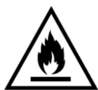
WARNING! Flammable refrigerant gas RISK OF FIRE HAZARD
PLEASE READ THE MANUAL CAREFULLY BEFORE USING THE PRODUCT.
When a FLAMMABLE REFRIGERANT is used, the appliance installation space requirements and/or ventilation requirements are determined by the amount of mass load(M) used in the appliance, the installation site and the type of site or appliance ventilation..
For models with R32 refrigerant:
The appliance shall be installed, operated and stored in a room With a floor area greater than 4m^2 .
For models with R290 refrigerant, the appliance shall be installed, operated and stored in a room with a floor area greater than 4m^2 :
Units <=9000Btu/h : 13m².
Units >9000Btu/h and <=12000Btu/h: 17m².
Units >12000Btu/h and <=18000Btu/h: 26m² Units >12000Btu/h and <=18000Btu/h:
26m² Units >18000Btu/h and <=18000Btu/h: 26m
Service
Any electrical work required to service the appliance must be carried out by a qualified electrician or competent person.
This product must be serviced by an authorised Service Centre, and only original spare parts must be used.
natural_image
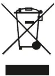
Symbol of a trash bin with crossed lines indicating no waste or restriction, and a solid rectangle below (no text or labels)This symbol on the product or on its packaging indicates that this product must not be treated as household waste. Instead, it must be taken to the appropriate collection point for the recycling of electrical and electronic equipment.
By ensuring this product is disposed of correctly, you will help prevent potential negative consequences for the environment and human health, which could otherwise be caused by inappropriate waste handling of this product.
For more detailed information about recycling of this product, please contact your local authorities, your household waste disposal service or the shop where you purchased the product.
Packaging materials
Materials with the symbol container for recycling.

are recyclable. Please dispose of the packaging in a suitable collection
Disposal of the device
Disconnect the plug from the socket.
Cut the power cord and discard it.
Do not disassemble the product other than as described in the user manual. The product must not be disassembled by the user. At the end of its service life, the product must not be disposed of with household waste. Consult your local authorities or your supplier for advice on recycling.
Explanation of the symbols displayed on the indoor unit or outdoor unit
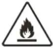 | WARNING | This symbol indicates that this product uses a flam-mable refrigerant. If the refrigerant leaks and is exposed to an external ignition source, there is a risk of fire. |
 | ATTENTION This symbol indicates that the operating instructions must be read carefully. | |
 | ATTENTION | This symbol indicates that this equipment must be handled by the service technician in accordance with the installation manual. |
 | ATTENTION | This symbol indicates that the service technician must handle this equipment in accordance with the installation manual. |
 | ATTENTION | This symbol indicates that information such as the instruction manual or installation manual is available. |
Important safety instructions for GAS containing devices
Workplace checks.
Before starting work on installations containing flammable refrigerants, safety checks must be carried out to ensure that the risk of fire is minimised. In the case of refrigeration system repair, the following precautions should be taken before carrying out any work on the installation.
Work procedure
Work should be carried out under a controlled procedure to minimise the risk of flammable gases or vapours being present while the work is being carried out.
Work area.
All maintenance personnel and others working in the area must be informed of the nature of the work being carried out. Avoid working in enclosed spaces.
Check for the presence of refrigerant
Before and during work, the area should be checked with a suitable refrigerant detector to ensure that the technician is aware of the existence of potentially toxic or flammable atmospheres. Ensure that the leak detection equipment being used is suitable for use with all applicable refrigerants, i.e. non-sparking, properly sealed or intrinsically safe.
Presence of a fire extinguisher.
If any work is to be carried out on the refrigeration equipment or any part thereof, suitable fire extinguishing equipment must be available. Have a dry powder or CO2 fire extinguisher next to the loading area.
There are no sources of ignition.
No person performing work in connection with a refrigeration system involving exposure of any piping shall use sources of ignition in such a manner as to cause a fire or explosion. All possible sources of ignition, including cigarette smoking, shall be kept sufficiently far away from the installation, repair, removal and disposal site, during which time refrigerant may be released into the surrounding space. Before work is carried out, the area around the equipment must be inspected to ensure that there are no ignition hazards or ignition risks. No smoking" signs shall be posted.
Ventilated area.
Ensure that the area is in the open air or adequately ventilated before accessing the system or performing any hot work. A certain degree of ventilation must be maintained during the work period. Ventilation should safely disperse any refrigerant that is released and preferably expel it outside into the atmosphere.
Checking refrigeration equipment.
When electrical components are replaced, they should be fit for purpose and to the correct specification. The manufacturer's maintenance and service guidelines shall be followed at all times. If in doubt, consult the manufacturer's technical department for assistance. The following controls shall apply to installations using flammable refrigerants.
Checks of electrical devices.
Repair and maintenance of electrical components should include initial safety checks and component inspection procedures. If there is a fault that could compromise safety, no electrical supply should be connected to the circuit until it is satisfactorily resolved. If the fault cannot be corrected immediately, but continued operation is necessary, a suitable temporary solution must be used. This shall be communicated to the owner of the equipment so that all parties are informed.
Initial safety checks shall include:
- that capacitors are discharged: this must be done in a safe manner to avoid the possibility of sparking;
- that no electrical components or wiring are exposed while charging, recovering or purging the system;
- That there is continuity of grounding.
Repair of sealed components.
During repairs to sealed components, all electrical supplies should be disconnected from the equipment being worked on before removing sealed covers, etc. If it is absolutely necessary to have power supply to the equipment during repairs, permanent leak detection must be carried out. This should be done at the most critical point to warn of a potentially dangerous situation.
Particular attention must be paid to the following to ensure that, when working with electrical components, the enclosure is not altered in such a way as to affect the level of protection. For example, damage to cables, excessive number of connections, terminals not made to the original specification, damage to seals, incorrect mounting of bushings, etc.
Ensure that the product is properly assembled.
Ensure that gaskets or sealing materials have not degraded to the point where they are no longer suitable for preventing the ingress of flammable atmospheres. Spare parts must conform to the manufacturer's specifications.
Repair of intrinsically safe components.
Do not apply any permanent inductive or capacitive load to the circuit without ensuring that it will not exceed the permissible voltage and current for the equipment in use.
Intrinsically safe components are the only ones that can be worked on in the presence of a flammable atmosphere. Test apparatus must be in the correct classification.
Replace components only with parts specified by the manufacturer. Other parts may cause ignition of the refrigerant in the atmosphere due to leakage.
Wiring
Check wiring for wear, corrosion, excessive pressure, vibration, sharp edges or any other adverse environmental effects. The check should also take into account the effects of ageing or continuous vibration from sources such as compressors or fans.
Detection of flammable refrigerants.
Under no circumstances should potential ignition sources be used when searching for or detecting refrigerant leaks. A halide torch (or any other detector using an open flame) must not be used.
Extraction and evacuation
When entering the refrigerant circuit for repairs, or for any other purpose, conventional procedures should be used. However, in the case of flammable refrigerants it is important that the procedure is the most appropriate, as combustion is a factor to be taken into account. The following procedure should be followed:
remove the refrigerant
purge the circuit with inert gas
evacuate
purge with inert gas
Open the circuit by cutting or welding
The refrigerant charge shall be recovered in suitable recovery cylinders. For products containing flammable refrigerants, the system must be purged with oxygen-free nitrogen to make the product safe for flammable refrigerants. This process may need to be repeated several times. Compressed air and oxygen should not be used to purge refrigerant systems.
For products containing flammable refrigerants, refrigerant flushing should be performed by breaking the vacuum in the system with oxygen-free nitrogen and continuing to fill until working pressure is reached, then venting to atmosphere and finally lowering to vacuum. This process must be repeated until there is no refrigerant in the system. When the final charge of oxygen-free nitrogen is used, the system must be vented to atmospheric pressure in order to perform the work. This operation is absolutely vital for brazing operations performed on piping.
Make sure that the vacuum pump outlet is not close to any possible source of ignition and that ventilation is available.
Charging procedures
In addition to conventional charging procedures, the following requirements must be followed:
Ensure that you do not contaminate yourself with different refrigerants when using the charging equipment. Hoses or lines should be kept as short as possible to minimise the amount of refrigerant they contain.
Cylinders should be kept in the proper position according to the instructions.
Ensure that the refrigeration system is grounded before charging with refrigerant.
Label the equipment when charging is complete (if not already done).
Great care must be taken not to overcharge the refrigeration system.
Note: Before refilling the system, the system shall be pressure tested with the appropriate purge gas. The system shall be leak tested at the end of charging but before commissioning. A follow-up leak test shall be carried out before leaving the site.
Disassembly
Before carrying out this procedure, it is essential that the technician has a thorough knowledge of the equipment and all its details. It is recommended as good practice that all refrigerants are safely recovered. Before carrying out the task, a sample of oil and refrigerant should be taken in case an analysis is required before reusing the recovered refrigerant. It is essential that electrical power is available before starting the task.
Familiarise yourself with the equipment and its operation.
Electrically isolate the system.
Before attempting the procedure, ensure that technical equipment is available for handling refrigerant cylinders, if necessary;
Pump out the refrigerant system, if possible.
If vacuum is not possible, make a manifold so that refrigerant can be removed from various parts of the system.
Make sure that the cylinder is placed on the scale before recovery.
Start the recovery machine and operate it according to the instructions.
Do not overfill the cylinders (no more than 80% of the liquid charge volume).
Do not exceed the maximum working pressure of the cylinder, even temporarily.
When the cylinders have been correctly filled and the process has been completed, ensure that the cylinders and equipment are removed from the site promptly and that all isolation valves on the equipment are closed.
Recovered refrigerant should not be charged to another refrigeration system unless it has been cleaned and checked.
Labelling
Equipment shall be labelled indicating that it has been decomposed and drained of refrigerant. The label shall be dated and signed. In the case of equipment containing flammable refrigerants, it shall be ensured that there are labels on the equipment indicating that the equipment contains flammable refrigerant.
Recovery
When refrigerant is removed from a system, either for service or for shutdown, it is recommended as good practice that all refrigerants are disposed of safely.
When transferring refrigerant to cylinders, ensure that only suitable refrigerant recovery cylinders are used. Ensure that the correct number of cylinders are available to maintain the total system charge. All cylinders used are designated for the refrigerant recovered and labelled for that refrigerant (i.e. special refrigerant recovery cylinders). Cylinders must be complete with pressure relief valve and associated shut-off valves in good working order. Empty recovery cylinders are evacuated and, if possible, cooled prior to recovery.
Recovery equipment must be in good working order, with a set of equipment instructions at hand, and must be suitable for the recovery of all appropriate refrigerants, including, where appropriate, flammable refrigerants. In addition, a set of calibrated scales in good working order shall be available. Hoses shall be complete with disconnect couplings free of leaks and in good condition. Before using the recovery machine, check that it is in good working order, that it has been properly maintained and that all associated electrical components are sealed to prevent ignition in the event of refrigerant discharge.
Consult the manufacturer if in doubt. Recovered refrigerant shall be returned to the refrigerant supplier at the correct recovery site.
Installation overview
Select the installation location

natural_image
Pure mechanical diagram showing a lever mechanism with no text or symbolsDetermine the position of the hole in the wall
Attach the mounting plate
Drill a hole in the wall
natural_image
Diagram showing a pipe fitting being adjusted with a forceps, no text or symbols presentConnect the pipe
Connect the wiring
natural_image
Illustration of hands holding a small object with a ruler partially visible (no text or symbols)Prepare the drainage tube
natural_image
Diagram of a cable assembly with coiled and twisted wires, no text or symbols presentWrap pipes and cables
natural_image
Illustration of two hands holding a horizontal bar with three upward arrows, no text or symbols presentMount the indoor unit
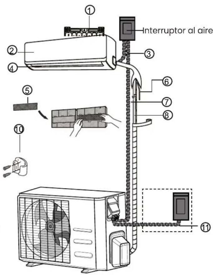
Parts of the unit
Note: Installation must be carried out in accordance with the requirements of local and national standards.
Installation may be slightly different in different areas.
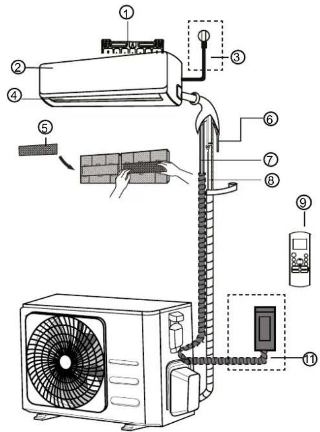
(1)
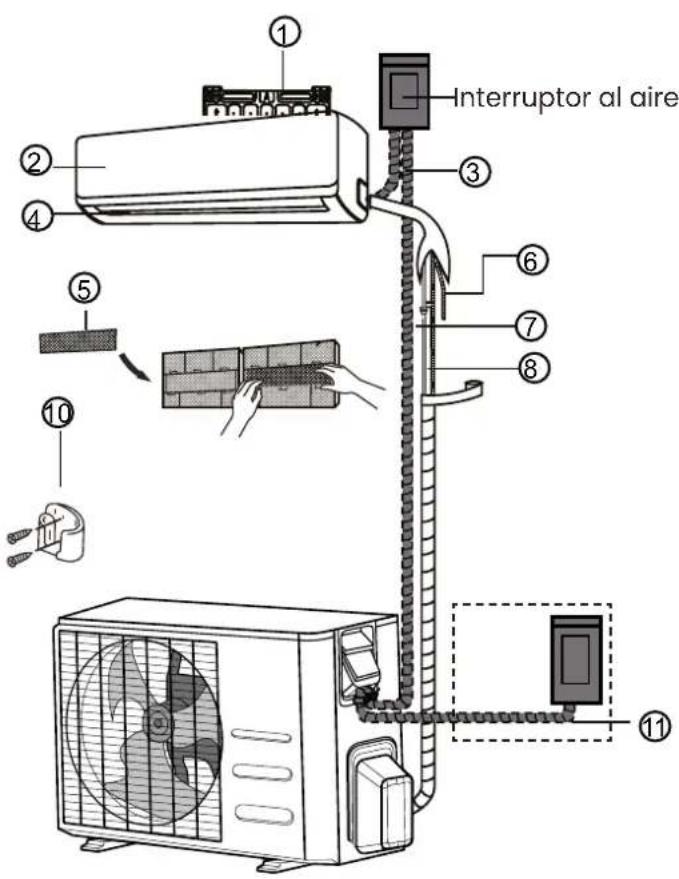
(2)
| 1 Wall mounting plate |
| 2 Front panel |
| 3 Power cable |
| 4 Flap / shutter |
| 5 | Functional filter |
| 6 | Drainage tube |
| 7 | Signal cable |
| 8 | Coolant pipe |
| 9 Remote control |
| 10 Remote control bracket(some units) |
| 11 Outdoor unit power supplycable (some units) |
The illustrations in this manual are for explanatory purposes. The actual shape of your indoor unit may be slightly different. Be guided by the actual shape.
Installing the indoor unit
Before installing the indoor unit, check the label on the product box to make sure that the model number of the indoor unit matches the model number of the outdoor unit.
Step 1: Select a good installation location
Before installing the indoor unit, you must choose a suitable location. Below are the requirements that will help you choose a suitable location for the unit.
A suitable installation location has the following characteristics:
Good air circulation
Adequate drainage
Noise from the unit will not disturb other people
firm and solid - the location will not vibrate
Strong enough to support the weight of the unit
A location at least one metre away from all other electrical devices (e.g. TV, radio, computer...)
DO NOT install the unit in the following locations:
Near any source of heat, steam or combustible gas.
Near any flammable items such as curtains or clothing
Near any obstacle that may block air circulation
Near the door
In a place exposed to direct sunlight
Note about the hole in the wall:
If fixed refrigerant piping is not available:
When choosing a location, please note that you must leave enough space for a hole in the wall (refer to Drilling the hole in the wall for the passage of the connective piping) for the signal cable and refrigerant piping connecting the indoor and outdoor unit.
The default position for all piping is on the right side of the indoor unit (facing the unit). However, the unit can accommodate both left and right piping.
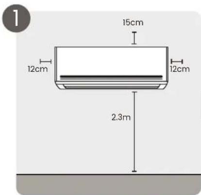
Refer to the diagram below to ensure proper distance from the walls and ceiling:
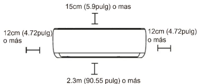
Step 2: Attaching the mounting plate to the wall
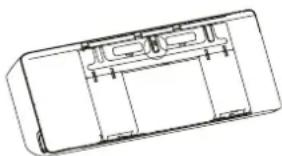
The mounting plate is the device on which the indoor unit is mounted.
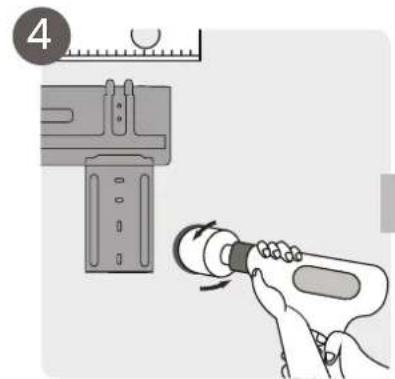
Remove the mounting plate located on the back of the indoor unit.
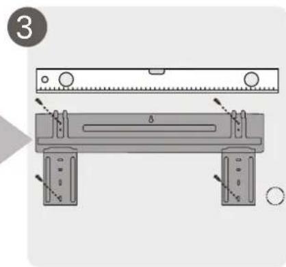
Attach the mounting plate to the wall with the supplied screws. Make sure that the mounting plate is flat against the wall.
NOTE FOR BRICK WALLS:
If the wall is made of brick, concrete, or similar material, drill 5 mm diameter holes in the wall and insert the socket anchor bolts
supplied. Then attach the mounting plate to the wall by tightening the screws directly into the clip anchors.
natural_image
Technical line drawing of a rectangular electronic component or enclosure with internal compartments (no text or symbols)Step 3: Drill a hole in the wall for the pipe connection.
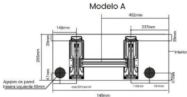
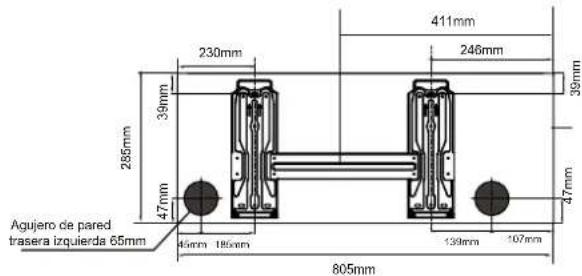
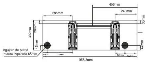
- Determine the location of the hole in the wall based on the position of the mounting plate.
Refer to Mounting Plate Dimensions. - Using a 65mm or 90mm drill (depending on models), drill a hole in the wall. Make sure the hole is drilled at a slightly downward angle, so that the outer end of the hole is lower than the inner end by approximately 5mm to 7mm. This will ensure proper water drainage.
- Place the wall protection cap over the hole. This protects the edges of the hole and will help to seal the hole when the installation process is complete.
CAUTION
When drilling the hole in the wall, be sure to avoid cables, leads and other sensitive components.
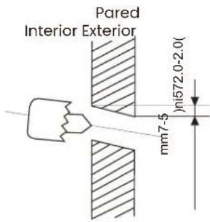
Mounting plate dimensions
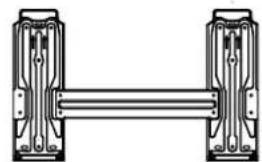
We can find different mounting plates for different air conditioner models. For different customisation requirements, the shape of the mounting plate may be slightly different. But the installation dimensions are the same for the same indoor unit size.
See Type A and Type B on the right.
Correct orientation of the mounting plate:
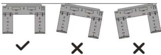
Nota: When the gas side connective pipe is 16mm diameter or more, the wall bore must be 90mm.
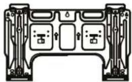
natural_image
Pure electrical circuit lines without any symbolsTipo A
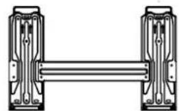
natural_image
Pure mechanical linkage diagram showing two vertical components connected by a horizontal bar (no text or symbols)T
ipo B
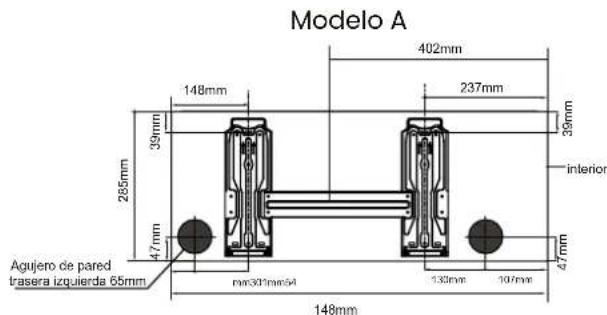
Modelo B
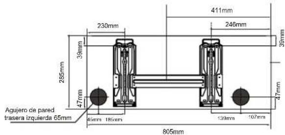
Modelo C
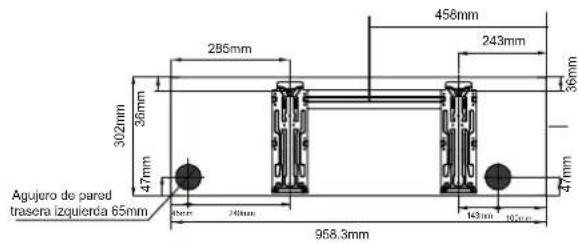
Step 4: Prepare the refrigerant line
The refrigerant pipe is located inside an insulated sleeve attached to the back of the unit.
You must prepare the pipe before passing it through the hole in the wall.
- Depending on the position of the hole in the wall in relation to the mounting plate, choose the side from which the piping will exit the unit.
- If the hole in the wall is behind the unit, hold the removable panel in place. If the hole in the wall is next to the indoor unit, remove the plastic panel from that side of the unit.
unit.
This will create a slot through which your pipe can exit the unit. Use needle nose pliers if the plastic panel is too difficult to remove by hand.
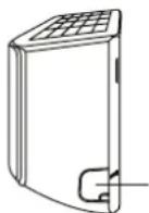
Panel desmontable
- If the connection pipe is already recessed in the wall, go directly to the section "Connecting drain pipe". If there is no recessed piping, connect the refrigerant piping from the indoor unit to the connecting piping that will join the outdoor and indoor units. Refer to the "Refrigerant pipe connection" section of this manual for detailed instructions.
Note on piping angles:
The refrigerant piping can exit the indoor unit from four different angles: left, right, left rear, left rear, right rear.
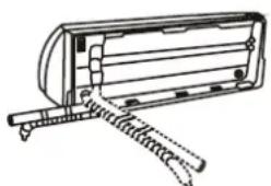
natural_image
Line drawing of a mechanical device with spring and lever components (no text or symbols)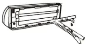
natural_image
Line drawing of a mechanical device with a spring and handle (no text or symbols)CAUTION
Step 5: Connecting the drain hose
By default, the drain hose is connected to the left side of the unit (facing the rear of the unit). (facing the rear of the unit).
However, it can also be mounted on the right side. To ensure proper drainage, attach the drain hose on the same side where the refrigerant pipe exits the unit. Connect the drain hose extension (purchased separately) to the end of the drain hose. drain hose.
Wrap the connection point tightly with Teflon tape to ensure a good seal and prevent leakage.
For the part of the drain hose that will remain inside, wrap it with foam insulation to prevent condensation.
Remove the air filter and pour a small amount of water into the drain pan to ensure that water flows smoothly from the unit.
Note: Be sure to attach the drain hose according to the figures on the right:
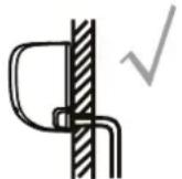
Make sure there are no kinks or dents in the drain hose to ensure proper drainage.
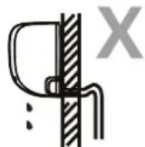
Kinks in the drain hose can cause wa- ter leaks.
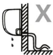
Kinks in the drain hose can cause wa- ter leaks.
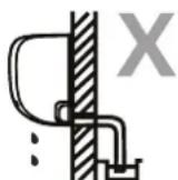
Do not place the end of the drain hose in water or in containers that collect water. This will hinder proper drainage.

Plug the unused drain hole. To prevent unwanted leakage, you must plug the unused drain hole with the plug provided.
! BEFORE CARRYING OUT ANY ELECTRICAL WORK, READ THESE REGULATIONS
-
All wiring must comply with local and national electrical codes and regulations and must be installed by a licensed electrician.
-
All electrical connections must be made in accordance with the wiring diagram found on the indoor and outdoor unit panels.
-
If there is a serious safety problem with the power supply, stop work immediately. Explain your reasoning to the customer and refuse to install the unit until the safety problem is properly resolved.
-
The power supply voltage must be within 90-110% of the rated voltage. Insufficient power supply may cause malfunction, electric shock or fire.
-
If connecting the power supply to fixed wiring, a surge protector and main power switch must be installed.
-
If power is connected to fixed wiring, a switch or circuit breaker that disconnects all poles and has a contact separation of at least 1/8 inch (3 mm) must be incorporated in the fixed wiring. The qualified technician must use an approved circuit breaker or switch.
-
Connect the unit only to an individual branch circuit outlet. Do not connect another appliance to that outlet.
-
Be sure to ground the air conditioner properly.
-
All wiring must be securely connected. Loose wiring may cause the terminal to overheat, resulting in product malfunction and possible fire.
-
Do not allow the wires to touch or rest against the refrigerant pipe, compressor or any moving parts inside the unit.
-
If the unit has an auxiliary electric heater, it must be installed at least 1 metre away from any combustible material.
-
To avoid receiving an electric shock, never touch electrical components shortly after the power supply has been cut off. After disconnecting the power, always wait 10 minutes or more before touching electrical components.

WARNING!
Before carrying out any electrical or wiring work, disconnect the main power supply to the system.
Step 6: Connecting the signal and power cables
The signal cable enables communication between the indoor and outdoor unit. You must first choose the appropriate wire gauge before preparing it for connection.
Cable types:
- Indoor power cable (if applicable): H05VVV-F
Indoor power cable (if applicable): H05VVV-F or H05V2V2-F
- Outdoor power cable:
H07RN-F
- Signal cable: H07RN-F
Choose the appropriate wire gauge.
The required gauge of power wire, signal wire, fuse, and switch is determined by the maximum current rating of the unit. The maximum current is indicated on the nameplate located on the side panel of the unit. Refer to this nameplate to select the appropriate wire, fuse, or circuit breaker.
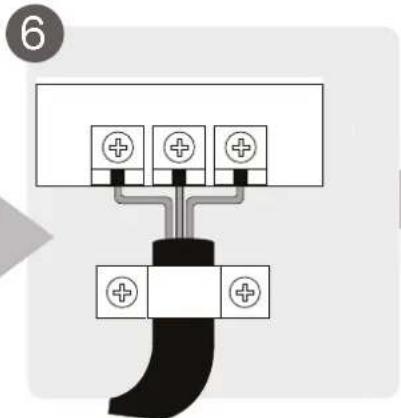
- Open the front panel of the indoor unit.
- Using a screwdriver, open the cover of the cable box on the right side of the unit.
box cover on the right side of the unit.
Note: All wiring must be carried out strictly strictly in accordance with the wiring diagram located on the back of the front panel of the control unit.
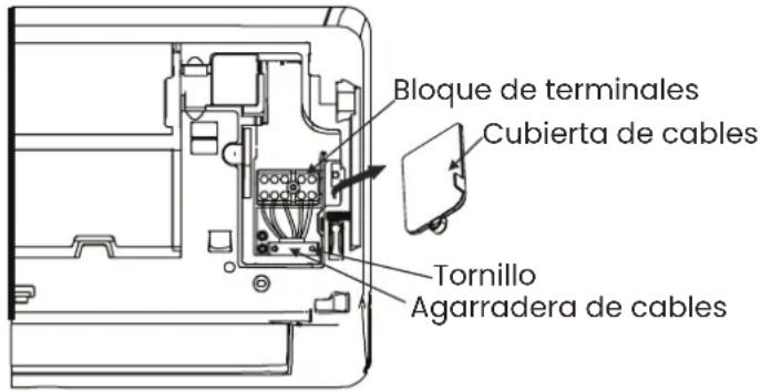
-
Unscrew the cable clamp underneath the terminal strip and position the cable laterally.
-
Facing the rear of the unit, remove the plastic panel on the lower left side.
-
Route the signal cable through this slot, from the back of the unit to the front.
-
In front of the front of the unit, connect the cable according to the wiring diagram of the indoor unit, connect the U-plug and screw each cable firmly to its corresponding terminal.
screw each wire tightly to its corresponding terminal.
-
After checking that all connections are secure, use the clamp to fix the signal cable to the unit. Screw the cable clamp firmly.
-
Replace the wire cover on the front of the unit and the plastic panel on the back.
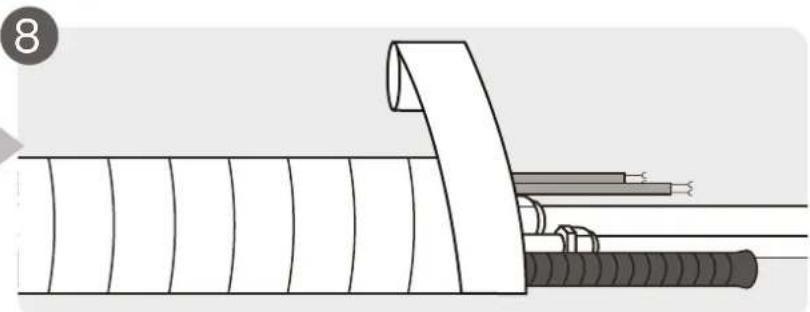
Step 7: Wrap the pipes and cables
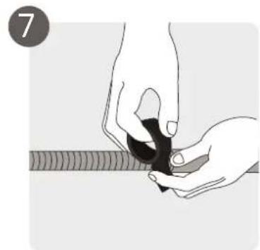
Before passing the pipe, drain hose and signal cable through the hole in the wall, you must bundle them together to save space, protect and insulate them.
- Wrap the drain hose, refrigerant pipes and signal cable as shown in the figure on the right.
Unidad interior:
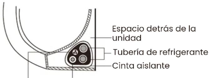
Note: The drain hose must be at the bottom:
Make sure the drain hose is at the bottom of the beam. Placing the drain hose at the top of the beam may cause the drain pan to overflow, which may result in fire or water damage.
Note: When bundling these items, do not intertwine or cross the signal cable with any other cable.
-
Using vinyl tape, attach the drain hose to the bottom of the coolant tubes.
-
Using duct tape, wrap the signal wire, coolant tubes and drain hose tightly together. Check that all items are packaged.
Note: Do not wrap the ends of the pipes.
When wrapping the bundle, keep the pipe ends unwrapped. You need access to them to check for leaks at the end of the installation process (refer to the Electrical Checks and Leak Checks section of this manual).
Step 8: Mount the indoor unit
If you have installed new connection piping to the outdoor unit, do the following:
- If you have already passed the refrigerant pipe through the hole in the wall, continue with step 4.
- Otherwise, check that the ends of the refrigerant pipes are sealed to prevent dirt or foreign materials from entering the pipes.
-
Slowly pass the wrapped bundle of refrigerant tubing, drain hose and signal cable through the hole in the wall.
-
Hook the upper part of the indoor unit onto the upper hook of the mounting plate.
- Check that the unit is securely hooked into the mounting by exerting slight pressure on the left and right sides of the unit. The unit should not shake or move.
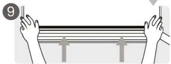
- Using even pressure, push down on the bottom half of the unit. Continue to push down until the unit snaps into the hooks along the bottom of the mounting plate.
- Again, check that the unit is firmly engaged in the mounting by exerting slight pressure on the left and right sides of the unit.
If the refrigerant piping is already recessed in the wall, do the following:
- Hook the top of the indoor unit into the top hook on the mounting plate.
- Use a bracket or a wedge to prop up the unit, which will give you enough room to
- Use a bracket or a wedge to prop up the unit, which will give you enough space to connect the refrigerant pipe, signal wire and drain hose.
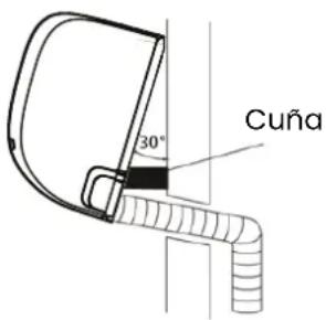
- Connect the drain hose and coolant pipe (refer to the Coolant Pipe Connection section of this manual for instructions).
- Keep the pipe connection point exposed for leak testing (refer to the Electrical Checks and Leak Checks section of this manual).
- After the leak test, wrap the connection point with duct tape.
- Remove the bracket or wedge holding the unit.
- Using even pressure, push down on the bottom half of the unit. Continue to push down until the unit snaps into the hooks along the bottom of the mounting plate.
The unit is adjustable
Note that the hooks on the mounting plate are smaller than the holes on the back of the unit. If you do not have enough space to connect recessed piping to the indoor unit, the unit can be adjusted to the left or right by 30-50 mm, depending on the model.
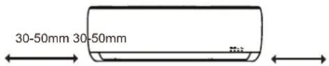
Installing the outdoor unit
Install the unit according to local codes and regulations, there may be slight differences between different regions.
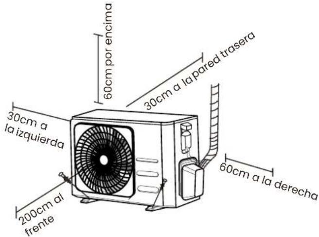
Step 1: Selecting a good location for installation
Before installing the outdoor unit, you must choose a suitable location. Below are the requirements that will help you choose a suitable location for the unit.
A suitable installation location has the following characteristics:
Meets all space requirements shown in the installation space requirements above.
Good air circulation and ventilation
Firm and solid - the location can support the unit and will not vibrate.
Noise from the unit will not disturb other people
Ensure that the outdoor unit is protected from prolonged periods of direct sunlight or rain.
When snowfall is expected, take appropriate measures to prevent ice build-up and damage to the coils.
DO NOT install the unit in the following locations:
Near an obstacle that blocks air inlets and outlets.
Near a public street, crowded areas or where noise from the unit may disturb others.
Near animals or plants that may be damaged by the hot air discharge.
Near any source of combustible gas
In a location exposed to large amounts of dust.
In a location exposed to excessive amounts of salt air.
Special considerations for extreme weather conditions extreme weather conditions
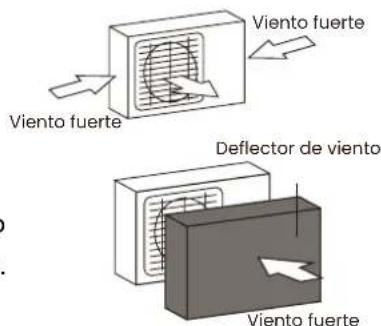
If the unit is exposed to strong winds: Install the unit so that the exhaust fan is at a 90^ angle to the wind direction. If necessary, build a barrier in front of the unit to protect it from extremely strong winds. See illustrations below. If the unit is frequently exposed to heavy rain or snowfall:
Construct a shelter over the unit to protect it from rain or snow. Be careful not to obstruct the airflow around the unit. If the unit is frequently exposed to salty (coastal) air: Use an outdoor unit specially designed to resist corrosion.
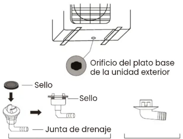
Step 2: Install the drainage gasket (heat pump unit only)
Before screwing the outdoor unit in place, you must install the drainage gasket on the bottom of the unit.
Note that there are two different types of drainage gaskets depending on the type of outdoor unit.
If the drainage gasket comes with a rubber seal (see Fig. A), do the following:
- Place the rubber seal on the end of the drain gasket that will be connected to the outdoor unit.
- Insert the drain gasket into the hole in the pan at the base of the unit. 3.
- Turn the drain gasket 90° until it snaps into place facing the front of the unit.
- Attach a drain hose extension (not included) to the drain joint to redirect water from the unit during heating mode.
If the drain joint does not come with a rubber gasket (see Fig. B), do the following:
- Insert the drain gasket into the hole in the pan at the base of the unit. The drain gasket will snap into place.
- Connect a drain hose extension (not included) to the drain joint to redirect the water from the unit during heating mode.
Note: In cold climates, make sure the drain hose is as vertical as possible to ensure rapid drainage of water. If the water drains too slowly, it may freeze in the hose and flood the unit.
Step 3: Anchoring the outdoor unit
The outdoor unit can be anchored to the floor or to a wall bracket with a bolt (M10). Prepare the installation base of the unit according to the dimensions given below:
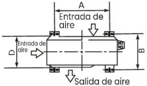
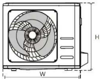
natural_image
Technical line drawing of a mechanical fan or air conditioning unit with dimension labels H and W (no text or symbols on the diagram itself)| Dimensions of the outdoor unit in mm. H x W x D | Mounting dimensions | |
| Distance A (mm) | Distance B (mm) | |
| 434x681x285 460 292 | ||
| 550x700x270 450 260 | ||
| 550x700x275 450 260 | ||
| 495x720x270 452 255 | ||
| 555x728x300 452 302 | ||
| 555x765x303 452 286 | ||
| 555x770x300 487 298 | ||
| 554x805x330 511 317 | ||
| 554x800x333 514 340 | ||
| 702x845x363 540 350 | ||
| 673x890x342 663 354 | ||
| 810x946x420 673 403 | ||
| 810x946x410 673 403 | ||
If you are installing the unit on the ground or on a concrete pad, do the following:
-
Mark the positions of the four expansion bolts according to the dimension table.
-
Pre-drill holes for the expansion bolts.
-
Place a nut on the end of each expansion bolt.
-
Hammer the expansion bolts into the pre-drilled holes.
-
Remove the nuts from the expansion bolts and place the outdoor unit on the bolts.
-
Place a washer on each expansion bolt and then replace the nuts.
-
Using a spanner, tighten each nut until snug.
Note: If drilling in concrete, eye protection is recommended at all times.
If you are installing the unit on a wall bracket, do the following:
- Mark the position of the holes in the bracket according to the dimension table.
- Pre-drill the holes for the expansion bolts.
- Place a washer and nut on the end of each expansion bolt.
- Thread the expansion bolts through the holes in the mounting brackets, place the mounting brackets in position and hammer into place.
- Thread the expansion bolts through the holes in the mounting brackets, place the mounting brackets in position and hammer the expansion bolts into the wall.
- Check that the mounting brackets are level.
- Carefully lift the unit and place the mounting feet on the brackets.
- Screw the unit firmly to the brackets.
- If permitted, install the unit with rubber gaskets to reduce vibration and noise.
Step 4: Connect the signal and power cables
The outdoor unit terminal block is protected by an electrical wiring cover on the side of the unit. Inside the wiring cover is a complete wiring diagram.

WARNING!
Before carrying out any electrical or wiring work, disconnect the main power supply to the system.
- Prepare the cable for connection.
Select the appropriate cable with reference to "Cable types". Choose the appropriate wire gauge:
The size of power wire, signal wire, fuse and circuit breaker required is determined by the maximum current rating of the unit, which is indicated on the nameplate located on the side panel of the unit
a. Using wire strippers, strip the rubber jacket from both ends of the cable to reveal approximately 40 mm of the inner wires.
b. Strip the insulation from the ends of the wires.
c. Using a crimper, insert the U-bolts into the ends of the wires.
-
Unscrew the electrical wiring cover and remove it.
-
Unscrew the cable clamp from the cable under the terminal strip and position the cable on its side.
-
Connect the cable according to the wiring diagram and screw the U-connector of each cable firmly to its corresponding terminal.
-
After checking that all connections are secure, coil the wires to prevent rainwater from flowing into the terminal.
-
Secure the cable to the unit with the cable clamp.
Screw the cable clamp tightly.
- Insulate unused cables with PVC electrical tape.
Position them so that they do not touch any electrical or metal parts.
- Replace the cable cover on the side of the unit and screw it into place.
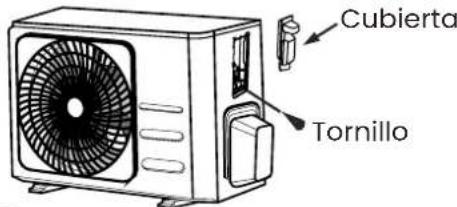
Note: If the cable clamp looks like the following, select the appropriate through hole according to the cable diameter.
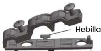
natural_image
3D mechanical component diagram showing a bracket with mounting holes and a central hole, labeled with dimension 'h' (no text or symbols beyond the label)Interconnection between indoor and outdoor unit
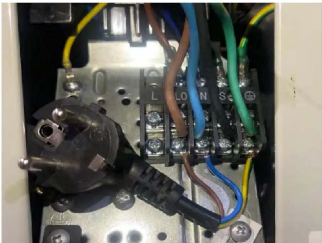
The following diagram shows the correct connection for split type air conditioners in the indoor and outdoor unit.
In the following connection terminal board we can see that the connection cable marked as L0 should be left unconnected, as it is a service port and is used for another type of connection.
Indoor unit
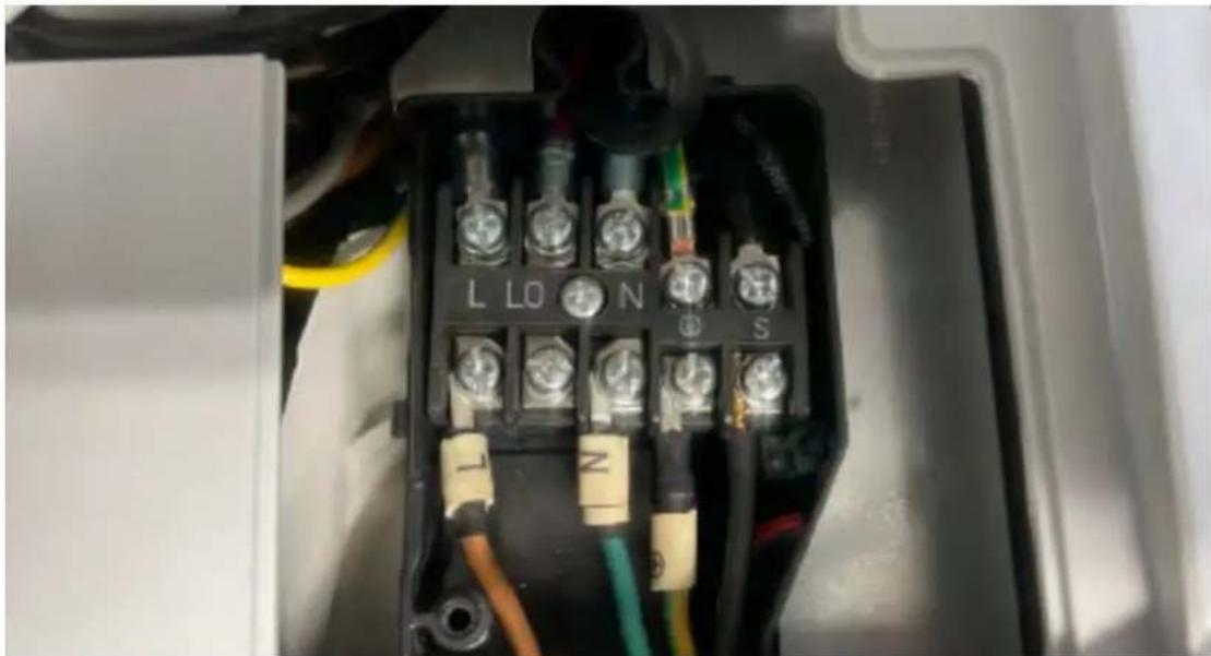
natural_image
Close-up of an electrical terminal block with labeled terminals (L, L0, N, S) and colored wires, no readable text or symbols beyond component labels.Outdoor unit
To connect the outdoor unit, we must make the connection at terminal L0, always leaving terminal L free. This prevents any communication error from appearing in our indoor unit.
natural_image
Electrical wiring and components inside an electrical enclosure, showing connections with no visible text or symbolsRefrigerant pipe connection
When connecting refrigerant piping, do not allow substances or gases other than the specified refrigerant to enter the unit. The presence of other gases or substances will reduce the capacity of the unit and may cause abnormally high pressure in the refrigerant cycle. This may cause explosions and injury.
Note: The length of refrigerant piping will affect the performance and energy efficiency of the unit. Rated efficiency is tested on units with a pipe length of 5 metres.
A minimum pipe length of 3 metres is required to minimise vibration and excessive noise. In special tropical areas, for R290 refrigerant models, refrigerant cannot be added and the maximum refrigerant pipe length must not exceed 10 metres. Refer to the following table for specifications on maximum pipe length and drop height.
Maximum length and drop height of refrigerant piping per unit model
| Model Capacity (btu/h) Long Max. (m) Max. drop height (m) | |||
| Split type air conditioner R410A, R32 | < 15,000 25 10 | ||
| ≥ 15,000 y < 24,000 30 | 20 | ||
| ≥ 24,000 y < 36,000 50 | 25 | ||
| R22 fixed speed air conditioner | < 18,000 10 5 | ||
| ≥ 18,000 y < 21,000 15 8 | |||
| ≥ 21,000 y < 35,000 20 | 10 | ||
| R410A, R32 fixed speed Split type air conditioner | < 18,000 20 8 | ||
| ≥ 18,000 y < 36,000 25 | 10 | ||
Connection instructions
Refrigerant piping
Step 1: Cutting pipe
When preparing the refrigerant pipes, take special care to cut and modify them properly. properly. This will ensure efficient operation and minimise the need for future maintenance. in the future.
- Measure the distance between the indoor and outdoor units.
- Using a pipe cutter, cut the pipe slightly longer than the measured distance.
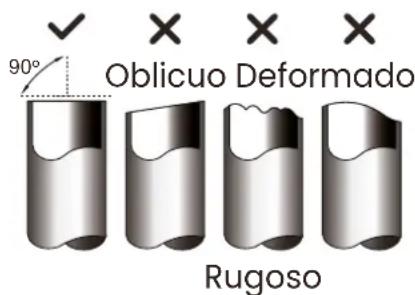
- Make sure the pipe is cut at a perfect 90^ angle.
Do not deform the pipe when cutting
Be very careful not to damage, dent or deform the pipe during cutting. This would drastically reduce the drastically reduce the heating efficiency of the unit.
Step 2: Remove burrs
Burrs can affect the tight seal of the refrigerant pipe connection.
They must be completely removed.
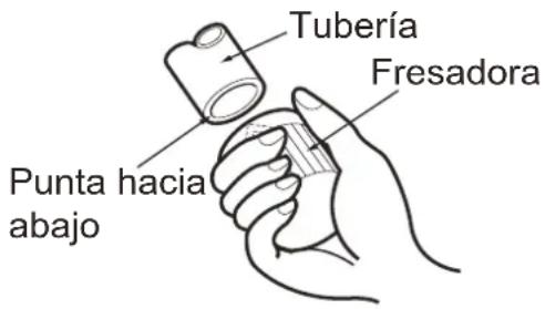
- Hold the pipe at a downward angle to prevent burrs from falling into the pipe.
- Using a burr or deburring tool, remove all burrs from the cut section of the pipe.
Step 3: Opening the ends of the tubes
Proper flaring is essential to achieve a watertight seal.
- After removing any burrs from the cut pipe, seal the ends with PVC tape to prevent foreign material from entering the pipe.
- Cover the pipe with insulating material.
- Place flare nuts on both ends of the pipe. Make sure they are facing the correct direction, as you cannot place them or change their direction after flaring.
- Remove the PVC tape from the ends of the pipe when you are ready to make the flare.
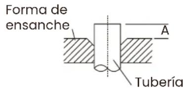
- Clamp flare form on the end of the pipe.
The end of the pipe should extend beyond the edge of the flare form in accordance with the dimensions shown in The end of the pipe must extend beyond the edge of the flare form in accordance with the dimensions shown in the table below:
- Place the flaring tool over the pipe.
- Turn the handle of the flaring tool clockwise until the pipe is fully flared.
- Remove the flaring tool, then inspect the end of the pipe for cracks and check the uniformity of the flaring.
Step 4: Connecting the piping
When connecting the refrigerant pipes, be careful not to over-tighten or deform the pipes in any way. The low pressure pipe must be connected first, then the high pressure pipe.
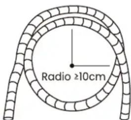
Minimum bending radius:
When bending refrigerant pipes, the minimum bending radius should be 10cm.
Instructions for connecting pipes to the indoor unit
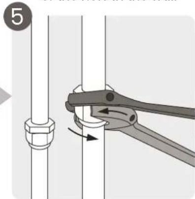
- Align the centre of the pipes to be connected.
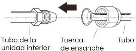
-
Tighten the flare nut as tight as possible by hand.
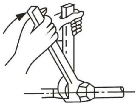
-
Using a spanner, tighten the hose nut on the unit.
-
While holding the nut firmly on the unit hose, use a torque wrench to tighten the nut.
While holding the nut firmly on the unit tube, use a torque spanner to tighten the flare nut as
- While holding the nut securely on the unit tube, use a torque wrench to tighten the flare nut according to the values in the torque requirement table below. Slightly loosen the flare nut and retighten it.
natural_image
Line drawing of hands using a tool to lift a mechanical component (no text or symbols)Tightening torque requirements
| Outer pipe diameter (mm) | Tightening torque(N·m) | Widening dimensions (B) (mm) |
| ∅ 6.35 (∅ 0.25") 18~20 | (180~200kgf.cm) 8.4~8.7 | (0.33~0.34") |
| ∅ 9.52 (∅ 0.375") 32~39 | (320~390kgf.cm) 13.2~13.5 | (0.52~0.53") |
| ∅12.7 (∅ 0.5") 49~59 | (490~590kgf.cm) 16.2~16.5 | (0.64~0.65") |
| ∅ 16 (∅ 0.63") 57~71 | (570~710kgf.cm) 19.2~19.7 | (0.76~0.78") |
| ∅ 19 (∅ 0.75") 67~101 | (670~1010kgf.cm) 23.2~23.7 | (0.91~0.93") |
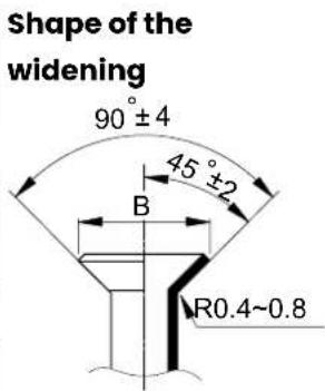
Note: Do not use excessive torque. Excessive force may crack the nut or damage the coolant pipe. Do not exceed the torque requirements shown in the table above.
Instructions for piping connection to the indoor unit
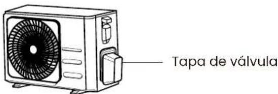
Unscrew the packed valve cover on the side of the outdoor unit. 2.
-
Remove the protective caps from the ends of the valves.
-
Align the flared end of the piping with each valve and tighten the flare nut as tight as possible by hand.
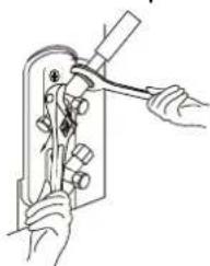
-
Using a spanner, grasp the valve body. Do not grasp the nut that seals the service valve.
-
While holding the valve body firmly, use a torque spanner to tighten the flare nut to the correct torque values.
-
Slightly loosen the flare nut and retighten it.
-
Repeat steps 3 to 6 for the rest of the pipe.
Note: Use a spanner to hold the main body of the valve.
Tightening torque on the flare nut may break other parts of the valve.
natural_image
Illustration of hands using a tool to adjust or install a mechanical component (no text or symbols visible)Air evacuation
Preparations and precautions
Air and foreign particles in the refrigerant circuit can cause abnormal pressure increases, which can damage the air conditioner, reduce its efficiency and cause injury. Use a vacuum pump and pressure gauge to evacuate the refrigerant circuit, removing any non-condensable gas and moisture from the system.
Evacuation should be performed at the time of initial installation and when the unit is placed in its original location.
Before evacuation:
Check that the connecting pipes between the indoor and outdoor unit are connected correctly.
Make sure that all wiring is properly connected.
Evacuation instructions
- Connect the pressure gauge charging hose to the service port of the outdoor unit's low pressure valve.
- Connect another pressure gauge charging hose to the vacuum pump.
- Open the low pressure side of the gauge. Keep the high pressure side closed.
- Turn on the vacuum pump to evacuate the system.
- Run the vacuum pump for at least 15 minutes, or until the compound gauge reads -76cmHG (-10 5Pa).
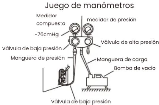
-
Close the low pressure side of the gauge and turn off the vacuum pump.
-
Wait 5 minutes and check that there has been no change in system pressure.
-
If there is a change in system pressure, refer to Checking for Gas Leaks section for information on how to check for leaks. If there is no change in system pressure,
unscrew the cap on the packed valve (high pressure valve).
- Insert the hex spanner into the packed valve (high pressure valve) and open the valve by turning the wrench 1/4 turn.
turn the spanner 1/4 turn counterclockwise. Listen for gas to come out of the system, then close the valve after
then close the valve after 5 seconds.
-
Observe the pressure gauge for one minute to ensure that there is no change in pressure. The gauge should indicate a pressure slightly above atmospheric pressure.
-
Remove the charging hose from the service port.
-
Using a hex spanner, fully open the high and low pressure valves.
valves fully open.
- Hand-tighten the caps on all three valves (service port,
high pressure, low pressure). If necessary, you can tighten them further with a torque spanner.
Note: When opening the valve stems, turn the hexagon spanner until it hits the stop.
Do not try to force the valve open further.
Important note on refrigerant charge
Some systems require additional charge depending on the length of the piping. The standard pipe length varies according to local regulations. For example, in North America, the standard standard pipe length is 7.5 m (23 ft).
In other areas, the standard pipe length is 5m. Refrigerant must be charged from the service port of the outdoor unit's low pressure valve. The additional refrigerant to be charged can be calculated using the following formula:
Refrigerant charge per pipe length
| Length of con-necting pipe (m) | Method of air purge | Additional coolant | |
| ≤ Standard tube length | Vacuum pump N/A | ||
| >Standard tube length | Vacuum pump Li-quid side: ∅ 6.35 (0 0.25") R32:(Tube length - standard leng-th) x 12g/m(Tube length - standard leng-th) x 0.13oz/ftR290:(Pipe length - standard length)x 10g/m (Pipe length - stan-dard length) x 0.10oz/ftR410A:(Pipe length - standard length)x 15g/m (Pipe length - stan-dard length) x 0.16 oz/ftR22:(Pipe length - standard length)x 20g/m (Pipe length - stan-dard length) x 0.21 oz/ft | Liquid side: ∅ 9.52 (0 0.375")R32:(Pipe length - standard length)x 24g/m (Pipe length - stan-dard length) x 0.26 oz/ft.R290:(Pipe length - standard length)x 18g/m (Pipe length - stan-dard length) x 0.19 oz/ft.R410A:(Pipe length - standard length)x 30g/m (Pipe length - stan-dard length) x 0.32 oz/ft.R22:(Pipe length - standard length)x 40g/m (Pipe length - stan-dard length) x 0.42 oz/ft | |
For the R290 refrigerant unit, the total quantity of refrigerant to be charged must not exceed greater than: 387g (<=9000Btu/h), 447g (>9000Btu/h and <=12000Btu/h), 547g (>12000Btu/h and <=18000Btu/h), 632g (>18000Btu/h and <=24000Btu/h). Refrigerant charge per tube length.
VERY IMPORTANT NOTE:
Do not mix refrigerants of different types.
Checklist before turning on your air conditioner
Complete the following checklist of checks to be carried out before switching on your air conditioner for the first time:
| List of checks to be carried out before first use YES / NO | ||
| Electrical safety checks | ||
| Gas leakage check | ||
| Confirm that liquid and gas openings are open | ||
| Verify that the remote control is working properly | ||
| Clean filters | ||
| No electrical leaks | ||
| Unit is properly grounded | ||
| All electrical terminals are properly covered | ||
| Indoor and outdoor units are solidly installed | ||
| No leaks at all pipe connection points | ||
| All piping is properly insulated | ||
| Unit performs HEAT function correctly | ||
| Indoor unit louvers rotate properly | ||
| Indoor unit responds to remote control | ||
Below is a detailed explanation of all the checks to be made before switching on your air conditioner, to help you fill in this checklist.
Electrical and gas leakage testing
Before the function test
Only perform the function test after the following steps have been completed:
Electrical safety checks -Confirm that the unit's electrical system is safe and functioning properly.
Gas Leak Check - Check all flare nut connections and confirm that the system does not leak.
Confirm that the gas and liquid valves (high and low pressure) are fully open.
Electrical safety checks
After installation, confirm that all electrical wiring was installed in accordance with local and national regulations and in accordance with the installation manual.
Before the function test
Check the earthing work
Measure the grounding resistance by visual detection and with the grounding resistance tester. The grounding resistance must be less than 0.1 .
Note: This may not be necessary for some locations in North America.
During the function test
Check for Electrical Leakage
During the Run Test, use an electrical probe and a multimeter to perform a complete electrical leakage test.
If electrical leakage is detected, turn off the unit immediately and call a licensed electrician to find and resolve the cause of the leakage..

WARNING! RISK OF ELECTRIC SHOCK
All wiring must comply with local and national electrical codes and must be installed by a licensed electrician.
Gas Leak Checks
There are two different methods for checking for gas leaks.
Soap and water method
Using a soft brush, apply soapy water or liquid detergent to all pipe connection points of the indoor and outdoor unit. The presence of bubbles indicates a leak.
Leak detector method
If using a leak detector, refer to the instruction manual of the device for corresponding operating instructions.
After performing the gas leak check
After confirming that all pipe connection points are NOT leaking, replace the valve cover on the outdoor unit.
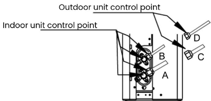
A: Low pressure shut-off valve
B: High pressure shut-off valve
C and D: Indoor unit flare nuts
Functional test
This test may take approximately 30 minutes.
- Turn on the power to the unit.
- Press the ON/OFF button on the remote control to turn it on.
- Press the MODE button to scroll through the following functions, one at a time:
- COOL - Select the lowest possible temperature.
- HEAT - Select the highest possible temperature.
- Allow each function to run for 5 minutes and perform the following checks:
| List of checks to be carried out Approved / Not approved | ||
| No electrical leakage | ||
| Unit is properly grounded | ||
| All electrical terminals are properly covered | ||
| Indoor and outdoor units are solidly installed | ||
| No leaks at all piping connection points Outdoor | (2): | Indoor (2): |
| Water drains properly from drain hose | ||
| All pipes are properly insulated | ||
| The unit performs the COOL function properly. | ||
| The unit performs the HEAT function properly | ||
| The louvers of the indoor unit rotate properly. | ||
| The indoor unit responds to the remote control | ||
Double checking of pipe connections
During operation, the pressure in the cooling circuit will increase. This may reveal leaks that were not present during the initial leak check. During the test run, take the time to check all refrigerant pipe connection points for leaks.
Refer to the Gas Leak Check section for instructions.
- Once the function test has been successfully completed and confirm that all items on the Checklist to be Performed have PASSED, do the following:
a. Using the remote control, return the unit to normal operating temperature.
b. Using duct tape, wrap the indoor refrigerant piping connections that were left uncovered during the indoor unit installation process.
If the ambient temperature is below 17^ C
You cannot use the remote control to activate the COOL function when the room temperature is below 17^ C.
ambient temperature is lower than 17^ C. In this case, you can use the MANUAL CONTROL button to test the COOL function.
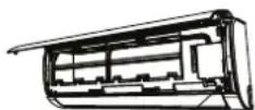
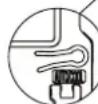
- Lift the front panel of the indoor unit and lift it up until it clicks into place.
- The MANUAL CONTROL button is located on the right side of the unit.
Press it 2 times to select COOL function. - Perform the test run as usual.
To further optimise the performance of your unit, do the following:
Keep doors and windows closed.
Limit energy consumption by using the TIMER ON and TIMER OFF functions.
OFF TIMER.
Do not block air inlets or outlets.
Regularly inspect and clean the air filters.
Operating temperature
When the air conditioner is operated in a temperature range other than those listed below, certain safety protection functions may be activated and the unit may be disabled.
Inverter type split
| COOL HEAT DRY | |||
| Room temperature | 17°C - 32°C 0°C - 30°C | 10°C - 32°C | |
| Outdoor temperature | 0°C - 50°C | -15°C - 30°C | 0°C - 50°C |
| -15°C - 50°C(For models with low temperature cooling systems). | |||
| 0°C - 52°C(For special tropical models) | 0°C - 52°C(For special tropical models) |
For outdoor units with electric auxiliary heater:
When the outdoor temperature is below 0 °C , we strongly recommend keeping the unit plugged in at all times to ensure continuous trouble-free operation.
Fixed speed type split
| COOL HEAT DRY | |||
| Room temperature | 17°C - 32°C 0°C - 30°C | 10°C - 32°C | |
| Outdoor temperature | 18°C - 43°C | -7°C - 24°C | 11°C - 43°C |
| -7°C - 43°C(For models with low temperature cooling systems). | 18°C - 43°C | ||
| 18°C - 52°C(For special tropical models) | 18°C - 52°C(For special tropical models) |
The relative humidity in the room is below 80%. If the air conditioner operates above this figure, the air conditioner surface may generate condensation. Set the vertical airflow louver to its maximum angle (vertically to the floor) and set the fan mode to HIGH.
Automatic restart (some units)
If the unit loses power, it will automatically restart with the previous settings once power is restored.
Anti allergen (some units)
When the unit is turned off from COOL, AUTO (COOL) or DEHUMIDIFIER modes.
Wifi Ready (some units)
Allows the air conditioner to be controlled via mobile phone and Wi-Fi connection.
Louver angle memory (some units)
When the unit is switched on, the louvre automatically returns to its previous angle.
Refrigerant leakage detection (some units)
The indoor unit will automatically display "EC" or "ELOC" or flash the LEDs (depending on the model) when it detects refrigerant leakage.
SLEEP mode
The SLEEP function is used to decrease power consumption while sleeping. This function can only be activated via the remote control. Sleep function is not available in
Dehumidifier
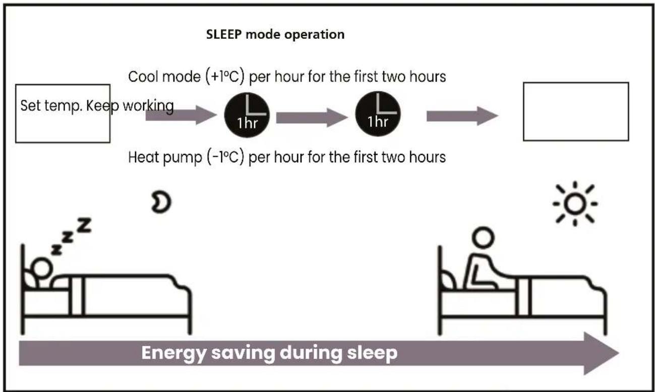
flowchart
graph LR
    A["Set temp. Keep working"] --> B["Cool mode (+1°C) per hour for the first two hours"]
    B --> C["Heat pump (-1°C) per hour for the first two hours"]
    C --> D["Energy saving during sleep"]
Adjusting the angle of the air flow
Vertical adjustment
While the unit is on, use the SWING/DIRECT button on the remote controller to adjust the direction (vertical angle) of the airflow. Refer to the remote controller manual for details.
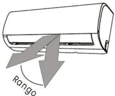
Do not move the grille by hand. This will cause the grille to become out of sync. If this happens, turn the unit off and unplug it for a few seconds, then restart the unit. This will reset the grille.
Note on moving angles:
When using COOL or DEHUMIDIFIER mode, do not place the grille at too vertical an angle for long periods of time. This may cause water to condense and drip onto the floor or furniture.
When using COOL or HEAT mode, placing the grille at too small an angle may reduce the performance of the unit due to airflow restriction. In accordance with the requirements of the relevant standards, adjust the vertical airflow grille to its maximum angle in the heating capacity test.
Horizontal adjustment
The horizontal angle of the airflow must be adjusted manually. Grasp the deflector rod (see illustration below) and adjust it manually in the preferred direction. On some units, the horizontal angle of the airflow can be adjusted by remote control.
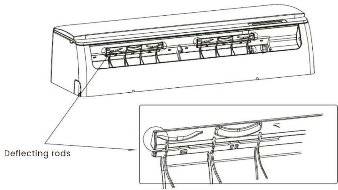
Manual adjustment (No remote control)
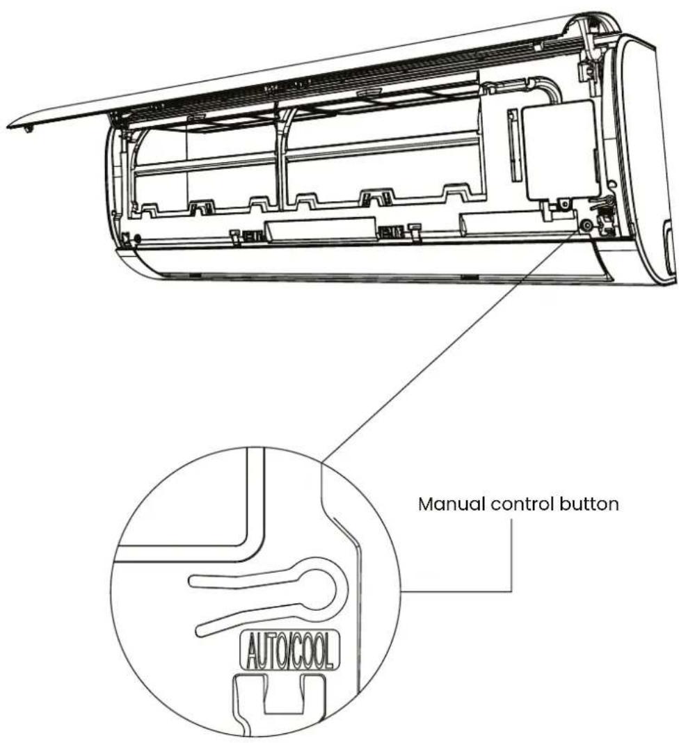
The manual button is only intended for testing and emergency operations. Do not use this function unless you have lost the remote control and it is absolutely necessary. To restore normal operation, use the remote control to activate the unit. The unit must be turned off before manual operation.
To operate your unit manually:
- Open the front panel of the indoor unit.
- Locate the MANUAL CONTROL button on the right side of the unit.
- Press the MANUAL CONTROL button once to activate the FORCED AUTO Mode.
- Press the MANUAL CONTROL button again to activate the FORCED COOLING Mode.
- Press the MANUAL CONTROL button a third time to turn the unit off.
- Close the front panel.
Note: Do not insert your fingers inside or near the fan and suction side of the unit. The high fan speed inside the unit may cause injury.
Remote control
- Before using the remote control for the first time, install the batteries and make sure that the "+" and "-" poles are inserted correctly.
- Make sure that the remote control is facing the signal reception window and that there are no obstacles in the way and that the distance is a maximum of 8m.
- Do not allow the remote control to fall down. Do not allow liquid to enter the remote control.
- Do not expose the remote control to direct sunlight or excessive heat.
- If the remote control does not operate normally, remove the batteries and reinsert them after 30 seconds. If this does not work, replace the batteries.
- When replacing batteries, do not mix old and new batteries or batteries of different types, as this may cause the remote control to malfunction.
- If you are not going to use the remote control for a long period of time, remove the batteries first, to prevent battery leakage from damaging the remote control.
- Dispose of used batteries properly.
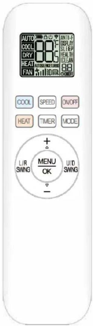
This is a universal remote control that provides all button functions. Please note that some of the buttons may not work, depending on the specific air conditioner you have purchased. (If a specific function is not available on the air conditioner, pressing the corresponding button will have no response).
HEAT and ELE.H functions are not available for air conditioner models without heat pump.
Replace remote control batteries
- Slide open the battery cover in the direction indicated by the arrowhead.
Insert two new batteries (7#), and place the batteries in the correct electrical poles (Positive and Negative).
- Replace the battery cover.
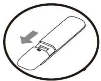
natural_image
Simple line drawing of a remote control device inside a circle (no text or symbols)
natural_image
Simple line drawing of a device with a handle and two cylindrical pins, enclosed in an oval (no text or symbols)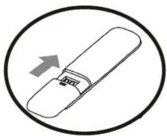
natural_image
Simple line drawing of a USB flash drive inside a circle (no text or symbols)1. ON/OFF
* Press this button to turn the unit on or off.
* This will clear the existing timer and SLEEP setting..
2. MODE
* Press this button to select the operating mode:
AUTO->COOL->DRY->HEAT->FAN->AUTO
(Auto->Cool->Dry->Dehumidifier->Heat->Fan->Auto)
Note: HEAT mode is not available for cooling only units.
3. Timer
With the unit on, press the TIMER button to turn the timer off or with the unit off to turn the timer on.
Press this button once and "ON(OFF)" will flash. Press "+" or "-" to set the number of hours the unit will turn on/off, with an interval of 0.5 hours, and a range of 0.5-24 hours.
Press it again to confirm the setting, "ON (OFF)" will stop flashing.
If the "TIMER" button is not pressed within 10 seconds after "ON (OFF)" starts flashing, the timer setting will be disabled.
If the timer setting is confirmed, press this button again to cancel the timer setting.
4. HEAT
Press this button to activate the heating mode.
5. COOL
Press this button to activate the cooling mode
6. SPEED
* Press this button to select the fan speed as follows:
Low -> Mid -> High -> Auto
The airflow speed in Auto mode is not available in Fan, TURBO and DEHUMIDIFIER mode.
7. Buttons +/-
* Each time “+” or “-” is pressed, the temperature setting increases or decreases by 1^(1^) .
* The temperature setting range is: 16°C(60°F) \~ 32°C(90°F).
Note: The temperature cannot be adjusted in automatic or fan mode.
8. Buttons MENU / OK
* Press the "MENU" button to enter the function selection mode.
Then press Up (+), Down (-), Left (L/R SWING) and Right (U/D SWING) to select the desired function. Then press the "OK" button to activate this function.
* In function selection mode, press Up (+), Down (-), Left (L/R SWING) and Right (U/D SWING), the LCD display character will blink if the function can be selected..
9. Swing keys left / right
Press this button to activate the left/right oscillation and press it again to deactivate it.
10. Up/down swing keys
Press this button to activate the left/right oscillation and press it again to deactivate it.
11. HEALTH
When the unit is on, press "MENU" button, then press Up(+), Down(-), Left(L/R SWING) and Right(U/D SWING) button to choose "HEALTH" symbol, when this symbol flashes, press "OK" button to select (not select) "HEALTH" symbol, which will activate (deactivate) the function.
12. SLEEP
With the unit power on, press "MENU" button, then press Up(+), Down(-), Left(L/R SWING) and Right(U/D SWING) button to choose "SLEEP" mode, when the "SLEEP" symbol flashes, press "OK" button to highlight (do not highlight) "SLEEP", which will activate (deactivate) the function of this mode.
The unit will end the SLEEP function after 10 hours of continuous operation and return to the previous state.
Note: SLEEP mode cannot be activated in fan or auto mode.
During sleep mode, the air conditioner display is off.
13. Display
Press "MENU" button, then press Up(+), Down(-), Left(L/R SWING) and Right(U/D SWING) to select "DISPLAY" function, when the "DISPLAY" symbol flashes, press "OK" button to activate (deactivate) the display display mode.
14. I-Clean
The unit will automatically clean the dust from the evaporator and dry or dehumidify the unit. When the air conditioner is off, press "MENU" button, then press Up(+), Down(-), Left(L/R SWING) and Right(U/D SWING) to choose "I-CLEAN" symbol, when the "I-CLEAN" symbol flashes, press "OK" button to activate (deactivate) that symbol, which will activate (deactivate) the cleaning function. Within one hour, this function will be automatically deactivated.
15. Child-Lock
Press the "HEAT" and "MODE" buttons at the same time and hold for at least 3 seconds to activate or deactivate the child lock function.
When the child lock function is activated, the "padlock" icon will be displayed on the remote control.
16. Anti-F
* Anti-F function: When the unit is off in cooling, dehumidifying or automatic (cooling) modes, it will continue to run for about 3 minutes to dehumidify the evaporator, in order to prevent the accumulation of bacteria in the evaporator, which cause fungus and strange odor and are harmful to health.
* When the unit is off, press "MENU" button, then press Up( + ),Down(-) button to choose "Anti-F" symbol, when the "Anti-F" symbol flashes, and press "OK" button to activate (deactivate) the "Anti-F" symbol, which will activate (deactivate) the Anti-F function..
17. °C/°F
The default temperature is displayed in degrees Celsius. Press the "COOL" and "HEAT" buttons at the same time for more than 3 seconds, and you can set the temperature in "°C" or "°F".
Note: Temperature display in Fahrenheit is not available for some models. When the temperature is displayed in Fahrenheit on the remote control, it may be displayed in Celsius on the unit, whose function and operation will not be affected.
18. Heating 8°C
* To activate or deactivate the 8°C heating function, press the "MODE" and "+" buttons simultaneously for more than 3 seconds.
* After activating the 8°C heating function:
a. Press the "HEAT" button, or change the mode, or select the sleep function, all can deactivate the 8^ heating function.
b. Press "SPEED", "+", "-" button has no effect.
c. Fahrenheit/Celsius change function is not effective.
d. Turn the unit off and on again, and the heating function at 8^ C will be maintained..
MODE OF USAGE
AUTO mode
- Press the "ON/OFF" button, and the air conditioner will start operating.
- Press the "MODE" button, and select the automatic operation mode.
- By pressing the "SPEED" button, you can select the fan speed between quiet, low, medium-low, medium, medium-high, high, high and automatic mode.
- Press the "ON/OFF" button again, and the air conditioner will stop.
Note: In automatic mode, the temperature setting is not effective.
Cool/Heat Mode
- Press the "ON/OFF" button, and the air conditioner will start operating.
- Press "MODE" button, select cool or heat operation mode.
- Press the "+" or "-" buttons to adjust the temperature between 16°C (60°F) and 32°C (90°F).
- By pressing the "SPEED" button, you can select the fan speed between quiet, low, medium-low, medium, medium-high, high, turbo and auto.
- Press the "ON/OFF" button again and the air conditioner will stop.
Note: The fan does not work in heat mode.
Fan mode
- Press the "ON/OFF" button, and the air conditioner will start operating.
- Press the "MODE" button, to select the fan operation mode.
- By pressing the "SPEED" button, you can select the fan speed from Low, Medium-Low, Medium, Medium-High, High, Turbo.
- Press the "ON/OFF" button again and the air conditioner will stop.
Note: In fan mode, the temperature settings are not effective.
Dry mode
- Press the "ON/OFF" button, and the air conditioner starts to operate.
- Press the "MODE" button, to select the dehumidifier operating mode.
- By pressing the “+” or “-” button, you can adjust the temperature from 16^ C ( 60^ F) to 32^ C ( 90^ F), the display changes as you press the button.
- Press the "ON/OFF" button again, and the air conditioner will stop.
Note: In dehumidifier mode, the speed setting is not effective.
Whenever there is a problem with the appliance, check if you can solve it by following the tables below. If the problem persists, contact customer service.
Note: Any electrical repairs to this product must comply with local, state, and federal laws. Please contact the Technical Support Center if you have any questions before performing any of the following before performing any of the above steps. Always disconnect the unit from the power supply when opening the unit.
| DESCRIPTION POSSIBLE CAUSE SOLUTION | ||
| Poor cooling • The set temperature may be higherthan the room temperature.Indoor or outdoor unit heat exchan-ger is dirty.The filter is dirty.The air inlet or outlet of either unit is blocked.Doors and windows are openDirect sunlight on either unitToo many heat sources in the room (people, computers, electronics, etc.).Low refrigerant level due to leakage or prolonged use.SILENCE function is activated (optio-nal function). | Reduce the set temperatureClean the affected heat exchangerRemove the filter and clean it according to the instructions.Turn the unit off, remove the obstruction and turn the unit back on.Make sure all doors and windows are clo-sed while the unit is operating.Close windows and curtains during pe-riods of high heat or intense sunshine.Reduce the number of heat sourcesCheck for leaks, reseal if necessary and refill with refrigerant.The SILENCE function may reduce the performance of the product by reducing the frequency of operation. Deactivate the SILENCE function. | |
| Unit does not work • Power failureThe power supply is disconnectedFuse is blown.Remote control batteries are ex-haustedThe 3-minute protection of the unit has been activated.Timer activated | Wait for the power to be restored.Turn on the powerReplace the fuseReplace the batteriesWait three minutes after restarting the unit.Turn off the timer | |
| DESCRIPCIÓN POSIBLE CAUSA SOLUCIÓN | ||
| The unit switches on and off frequently. | There is too much or too little refrigerant in the system.Incompressible gas or moisture has entered the system.Compressor is broken.Voltage is too high or too low | Check for leaks and recharge the system with refrigerant.Evacuate and recharge the system with refrigerant.Replace compressorInstall a manostat to regulate the voltage |
| Poor heating. • The outside temperature | ure is extremely low.Cold air entering through doors and windowsLow refrigerant level due to leakage or prolonged use. | Use an auxiliary heating device.Make sure all doors and windows are closed during use.Check for leaks, reseal if necessary and refill with refrigerant.. |
| The indicator lights are flashing. | The unit can either stop operation or continue to operate safely. If the indicator lights continue to flash or error codes appear, wait about 10 minutes. The problem may resolve itself.If it does not, turn the power off and then on again. Turn the unit back on.If the problem persists, disconnect the power and contact the nearest customer service centre. | |
| The error codeappears and starts withthe following letters on thedisplay of the indoor unitindoor unit:-E(x), P(x), F(x)-EH(xx), EL(xx), EC(xx)-PH(xx), PL(xx), PC(xx) | ||

WARNING! Before servicing or cleaning, the air conditioner must be disconnected from the mains.
Note: The exterior surfaces are susceptible to scratches and abrasions, so please follow the cleaning instructions to achieve the best possible result without damage.
General cleaning
Clean the surface of the device with a soft, damp cloth. Do not use chemical reagents such as alcohol, benzene and petrol, as they may damage the surface of the portable air conditioner.
Cleaning the filters
The filter should be cleaned once every two weeks. If the indoor air quality is poor, it must be washed more frequently or the performance of the appliance will be reduced because the filters may be clogged. Follow the instructions below for cleaning:
Lift the front panel of the indoor unit.
First press the tab on the end of the filter to loosen the clamp, lift it up and then pull it out.
Now pull out the filter.
If your filter has a small air freshener filter, unclip it from the larger filter.
Clean this air freshener filter with a hand hoover.
Clean the large filter with warm soapy water. Be sure to use a mild detergent.
Rinse the filter with fresh water, then squeeze out excess water.
Dry it in a cool, dry place and avoid exposing it to direct sunlight.
When it is dry, put the mbient filter back into the larger filter, then insert it back into the indoor unit.
Close the front panel of the indoor unit.
Note: Do not wash the filter at more than 40^ C or with abrasive and flammable products such as alcohol, gasoline and benzene. The filters should be kept away from heat sources as they may become deformed.
Never switch on the appliance without the filters correctly installed.
Do not touch the air freshener filter (Plasma) for at least 10 minutes after switching off the unit.
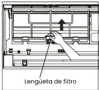
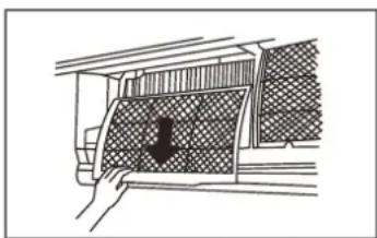
natural_image
Diagram of a hand holding a panel with a grid pattern, no text or symbols present
natural_image
Diagram showing a faucet above a grid-patterned room with a central object (no text or symbols)- Before changing the filter or cleaning, switch off the unit and disconnect it from the mains.
- When removing the filter, do not touch the metal parts of the unit. The sharp edges of the metal may hurt you.
- Do not use water to clean the inside of the indoor unit. This may damage the insulation and cause electric shock.
- Do not expose the filter to direct sunlight when drying. This may shrink the filter.
Air filter cleaning reminder After 240 hours of use, the indoor unit display will flash "CL". This is a reminder to clean the filter. After 15 seconds, the unit will return to its previous display.
To reset the reminder, press the LED button on your remote control 4 times, or press the MANUAL CONTROL button 3 times. If you do not reset the reminder, the "CL" indicator will flash again when you restart the unit.
Air filter replacement reminder After 2,880 hours of use, the indoor unit display will flash "nF". This is a reminder to replace the filter. After 15 seconds, the unit will return to its previous display.
To reset the reminder, press the LED button on your remote control 4 times, or press the MANUAL CONTROL button 3 times. If you do not reset the reminder, the "nF" indicator will flash again when you restart the unit.
Note: Any maintenance and cleaning of the outdoor unit must be performed by an authorized dealer or an authorized service provider. Any repairs to a unit must be carried out by an authorised dealer or authorised service provider.
Maintenance
If you plan not to use your air conditioner for an extended period of time, do the following:
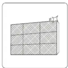
natural_image
Diagram of a 3D grid structure with a small arrow pointing to the top-right corner (no text or symbols)
natural_image
Simple line drawing of a house with wavy lines inside, enclosed in a rounded square (no text or symbols)natural_image
Line drawing of a smartphone with internal components (no text or symbols)- After long periods of non-use, or before periods of frequent use, do the following:
- Check for damaged cables.
- Clean all filters.
- Check for leaks
- Replace the batteries in the remote control.
- Make sure nothing is blocking the air inlets and outlets.
INFINITON
natural_image
Line drawing of a white air conditioner unit placed on a sofa in a living room (no text or symbols)Model: SPTMF12A2
ean: 8445639001028
natural_image
Illustration of a worker installing or adjusting an air conditioner on a lift (no text or symbols visible)
natural_image
Illustration of a worker in a hard hat installing or adjusting a wall-mounted device (no text or symbols visible)natural_image
Illustration of two workers installing a large air conditioner unit, surrounded by greenery and decorative elements (no text or symbols)Índice
Português
natural_image
Symbol of a trash bin with crossed lines indicating no waste or restriction, and a solid rectangle below (no text or labels)natural_image
Pure mechanical diagram showing a lever mechanism with no text or symbolsnatural_image
Technical diagram of a mechanical device with labeled components and alignment indicators (no readable text or symbols)natural_image
Illustration of a hand using a tool to adjust a component, with no visible text or symbols.natural_image
Mechanical diagram showing a tool interacting with a bolt and valve (no text or symbols present)Ligar o tubo
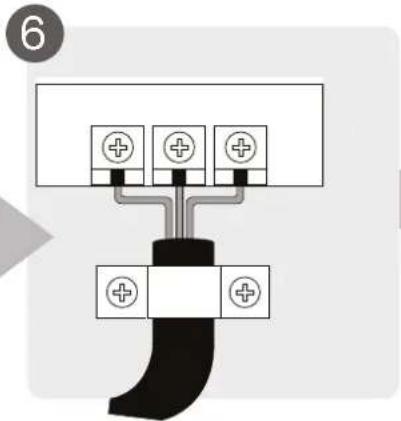
Ligar a cablagem
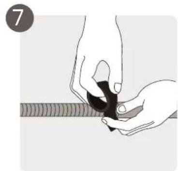
natural_image
Illustration of hands holding a small object with a ruler partially visible (no text or symbols)natural_image
Diagram showing cable installation with a coiled cable and clamped cable (no text or symbols)natural_image
Illustration of two hands holding a horizontal bar with three upward arrows, no text or symbols present(1)
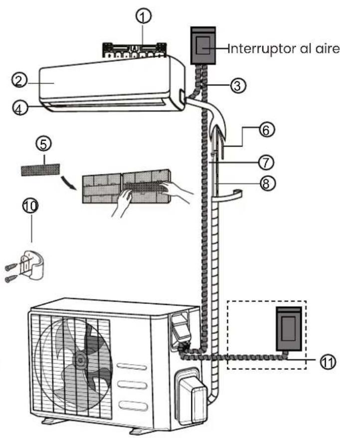
(2)
natural_image
Technical line drawing of a rectangular electronic component or enclosure with internal compartments (no text or symbols)natural_image
Pure electrical circuit lines without any symbolsTipo A
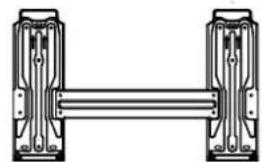
natural_image
Pure mechanical linkage diagram showing two vertical components connected by a horizontal bar (no text or symbols)T
ipo B
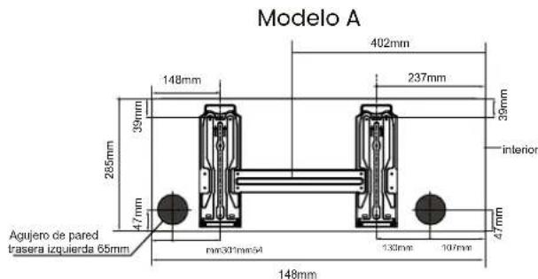
Modelo B
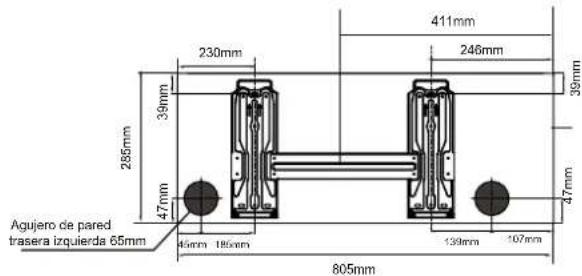
Modelo C
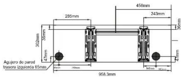
natural_image
Technical line drawing of a mechanical device with spring and handle (no text or symbols)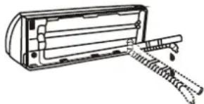
natural_image
Line drawing of a mechanical device with a handle and lever mechanism (no text or symbols)! CUIDADO
natural_image
Technical line drawing of a mechanical fan or air conditioning unit with dimension labels H and W (no text or symbols on the diagram itself)natural_image
Mechanical component labeled 'Hebilla' showing a bracket and mounting base (no other text or symbols visible)natural_image
3D mechanical component diagram showing a bracket with mounting holes and a central hole, no text or symbols present.natural_image
Close-up of an electrical terminal block with labeled terminals (L, L0, N, S) and wiring, no readable text or symbols beyond component labels.Unidade externa
natural_image
Electrical wiring and components inside a circuit board (no readable text or symbols)Passo 4: Ligar as tubagens
natural_image
Line drawing of hands using a tool to lift a mechanical component (no text or symbols)Requisitos de torque de aperto
| Diâmetro exterior do tubo (mm) | Torque de aperto(N·m) | Dimensões de alargamento (B) (mm) |
| ∅ 6.35 (∅ 0.25") 18~20 | (180~200kgf.cm) 8.4~8.7 | (0.33~0.34") |
| ∅ 9.52 (∅ 0.375") 32~39 | (320~390kgf.cm) 13.2~13.5 | (0.52~0.53") |
| ∅12.7 (∅ 0.5") 49~59 | (490~590kgf.cm) 16.2~16.5 | (0.64~0.65") |
| ∅ 16 (∅ 0.63") 57~71 | (570~710kgf.cm) 19.2~19.7 | (0.76~0.78") |
| ∅ 19 (∅ 0.75") 67~10 | (670~1010kgf.cm) 23.2~23.7 | (0.91~0.93") |
natural_image
Line drawing of a portable air conditioner unit with fan and control panel (no text or symbols)Tapa de válvula
natural_image
Illustration of hands using a tool to adjust or install a mechanical component (no text or symbols visible)Evacuação do ar
natural_image
Simple line drawing of a remote control device inside a circle (no text or symbols)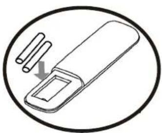
natural_image
Simple line drawing of a device with a handle and two cylindrical pins, enclosed in an oval (no text or symbols)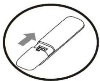
natural_image
Simple line drawing of a USB flash drive inside a circle (no text or symbols)1. ON/OFF
natural_image
Illustration of a hand pressing down on a patterned panel with a downward arrow (no text or symbols)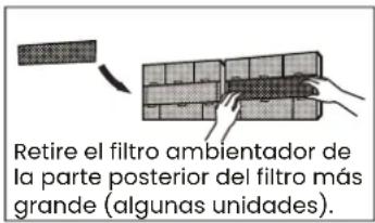
natural_image
Diagram showing a faucet above a grid-patterned panel with a central arrow (no text or symbols)natural_image
Diagram of a 3D grid structure with a small directional arrow pointing upward (no text or symbols)
natural_image
Simple line drawing of a house with wavy lines inside, enclosed in a rounded square (no text or symbols)natural_image
Line drawing of a smartphone internal components (no text or symbols)Retire as baterias do controlo remoto
¿Necesitas ayuda?
natural_image
Silhouette icon of a person wearing a headset with a wrench inside, symbolizing repair or maintenance (no text)
INFINITON
TÉRMINOS Y REGISTRO DE GARANTÍA
- Índice
- PRECAUCIÓN
- Unidad exterior
- Evacuación de aire
- ON/OFF
- Air conditioner type Split Section FIT Series CRUSH
- Your air conditioning, installed only by professionals
- Installation requirements
- Dual certification for highly polluting appliances
- What do Infiniton air conditioning filters do to protect you?
- a good night's sleep with sleep mode
- umidifying action
- Thorough cleaning with the iClean function
- Health mode
- WIFI connection
- Your air conditioner according to the size of your room
- Which type of air conditioner is most efficient and powerful for your home?
- How do I calculate consumption and power?
- Installation
- Maintenance
- PLEASE READ THE MANUAL CAREFULLY BEFORE USING THE PRODUCT.
- Service
- Packaging materials
- Disposal of the device
- Explanation of the symbols displayed on the indoor unit or outdoor unit
- Important safety instructions for GAS containing devices
- Workplace checks.
- Wiring
- Disassembly
- Labelling
- Recovery
- Installation overview
- Parts of the unit
- CAUTION
- ! BEFORE CARRYING OUT ANY ELECTRICAL WORK, READ THESE REGULATIONS
- WARNING!
- The unit is adjustable
- Air evacuation
- Evacuation instructions
- Electrical and gas leakage testing
- Before the function test
- WARNING! RISK OF ELECTRIC SHOCK
- Functional test
- Double checking of pipe connections
- If the ambient temperature is below 17° C
- To further optimise the performance of your unit, do the following:
- For outdoor units with electric auxiliary heater:
- SLEEP mode
- Adjusting the angle of the air flow
- Vertical adjustment
- Manual adjustment (No remote control)
- Remote control
- Replace remote control batteries
- MODE
- Timer
- HEAT
- COOL
- SPEED
- Buttons +/-
- Buttons MENU / OK
- Swing keys left / right
- Up/down swing keys
- HEALTH
- SLEEP
- Display
- I-Clean
- Child-Lock
- Anti-F
- °C/°F
- Heating 8°C
- MODE OF USAGE
- AUTO mode
- Cool/Heat Mode
- Fan mode
- Dry mode
- Cleaning the filters
- INFINITON
- ! CUIDADO
- Unidade externa
- Passo 4: Ligar as tubagens
- Evacuação do ar
- ¿Necesitas ayuda?
- TÉRMINOS Y REGISTRO DE GARANTÍA
Brand : Infiniton
Model : SPLIT-3726MF
Category : Air conditioner