Edimax ES-5816P - Network switch

ES-5816P - Network switch Edimax - Free user manual and instructions

Find the device manual for free ES-5816P Edimax in PDF.

📄 30 pages English EN Download 💬 AI Question 10 questions ⚙️ Specs
Notice Edimax ES-5816P - page 2
Pick your language and provide your email: we'll send you a specifically translated version.
Product Type 16-Port Fast Ethernet PoE Web Smart Switch
Ports 16 x 10/100 Mbps RJ-45 with PoE
PoE Standard IEEE 802.3af/at
PoE Power Budget 250W (estimated)
Management Web-based (HTTP), SNMP, Telnet (via web)
VLAN Support Port-based VLAN, 802.1Q Tagged VLAN, Multi-to-2 VLAN
Quality of Service (QoS) Priority modes: FIFO, All-High-before-Low, 4 Queue WRR; CoS based on TCP/UDP, IP TOS/DS, 802.1p, physical port
Security Features MAC address filter, TCP/UDP filter, password protection
Spanning Tree Protocol STP and RSTP support
Link Aggregation Up to 2 groups, 4 ports per group, LACP or static
Port Mirroring One-to-one, multi-to-one
Bandwidth Control Per-port ingress/egress rate limiting (32 Kbps or 512 Kbps resolution)
Broadcast Storm Control Threshold 1-63 packets per time unit
IGMP Snooping IGMP v1/v2
Configuration Backup/Restore Via web interface
Firmware Upgrade Via web (HTTP/TFTP)
Power Supply Internal, 100-240V AC, 50/60Hz
Dimensions (W x D x H) 440 x 230 x 44 mm (estimated)
Weight 2.5 kg (estimated)
Operating Temperature 0°C to 40°C (typical)
Certifications FCC, CE (assumed)

Frequently Asked Questions - ES-5816P Edimax

How do I access the web management interface?
Connect your PC to the switch via Ethernet. Set your PC's IP address to 192.168.2.x (e.g., 192.168.2.30) with subnet mask 255.255.255.0. Open a web browser and go to 192.168.2.1. The default username and password are both admin.
What are the default login credentials?
The default username is admin and password is admin. It is recommended to change the password after first login for security.
How do I reset the switch to factory defaults?
In the web interface, go to Administrator > Load Default Setting and click 'Load'. Note that the IP address, username, and password are preserved during this reset. Alternatively, a hardware reset button may be present.
Can I power devices using this switch?
Yes, the ES-5816P supports PoE (Power over Ethernet) on all 16 ports. It can supply power to compatible devices such as IP cameras, VoIP phones, and wireless access points. The total PoE power budget is estimated at 250W.
How do I configure VLANs?
Go to VLAN Setting > VLAN Mode to select between Port-based VLAN or Tagged VLAN (802.1Q). Then configure VLAN Membership under VLAN Member Setting. For a simple per-port VLAN, use Multi to 2 Setting.
How can I set bandwidth limits on a specific port?
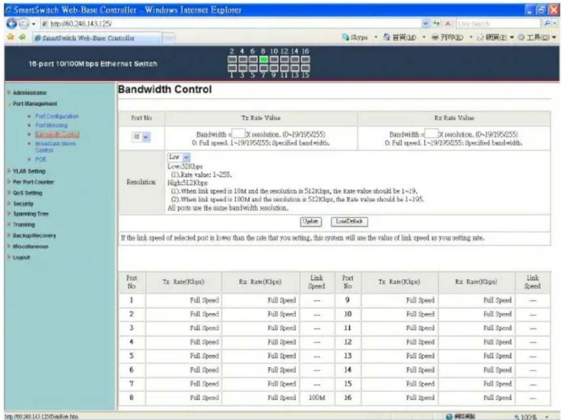
Navigate to Port Management > Bandwidth Control. Select the port number, then set the TX Rate Value and RX Rate Value (0 for full speed, 1-255 for a specified bandwidth). Choose the resolution: Low (32 Kbps) or High (512 Kbps). Click Update.
Why can't I access the web interface?
Ensure your PC is in the same subnet (192.168.2.x). Check that the switch is powered on and the Ethernet cable is properly connected. If the IP address was changed, try performing a factory reset (hold reset button for 10 seconds). Also disable any proxy settings in your browser.
How do I update the firmware?
Go to Administrator > Firmware Update. Enter the password (default admin) and confirm. Follow the on-screen instructions to upload the new firmware file. The switch may reboot automatically. Contact your reseller for the latest firmware.
What is the purpose of STP/RSTP?
Spanning Tree Protocol (STP) or Rapid Spanning Tree Protocol (RSTP) prevents network loops by creating a loop-free logical topology. It is essential when multiple paths exist between switches. Configure it under Spanning Tree > STP Bridge Settings.
How do I enable PoE on a specific port?
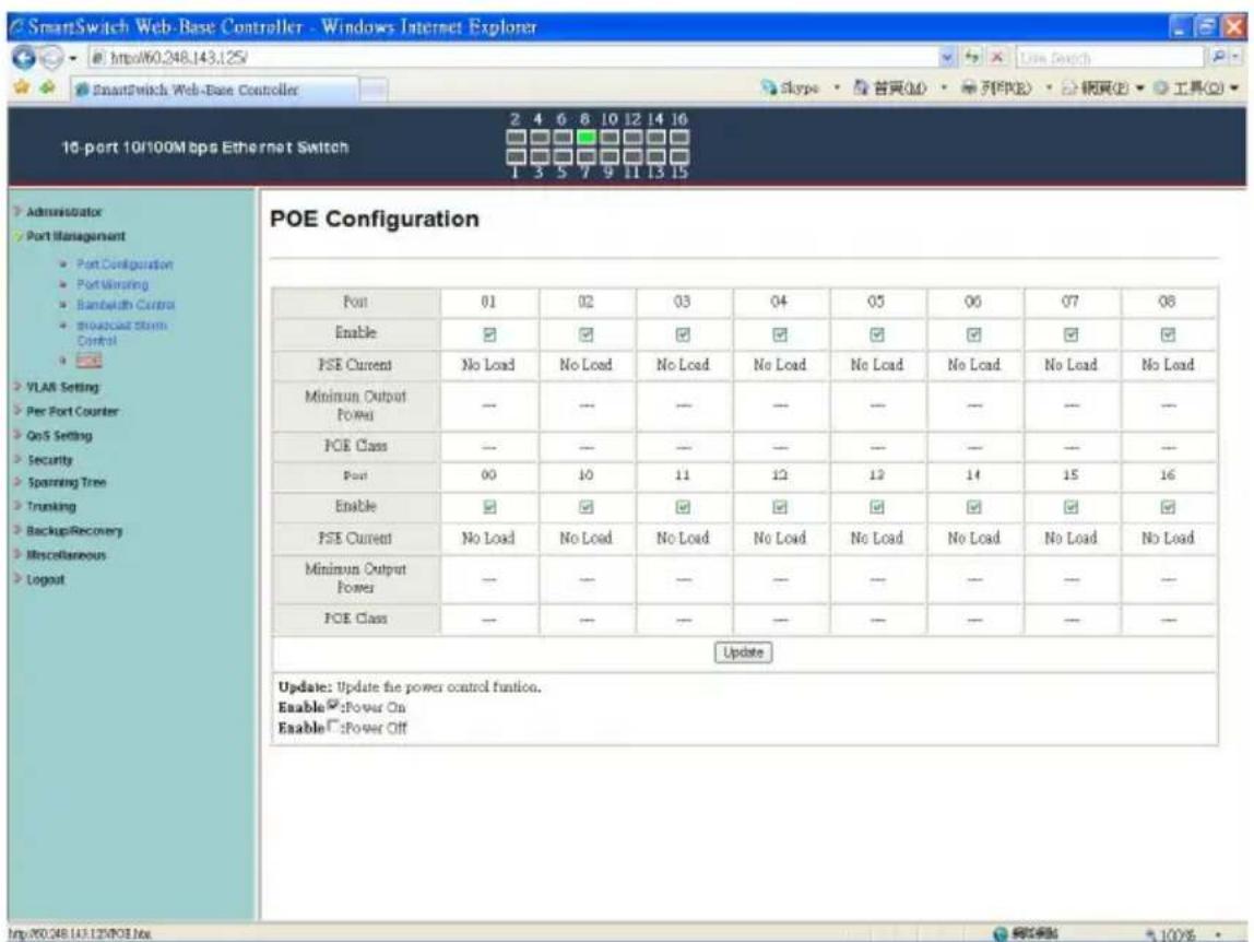
Go to Port Management > PoE Configuration. Each port has an Enable checkbox. Check it to supply power to the connected device. The status (PSE Current, POE Class) will update automatically.

User questions about ES-5816P Edimax

0 question about this device. Answer the ones you know or ask your own.

Ask a new question about this device

The email remains private: it is only used to notify you if someone responds to your question.

No questions yet. Be the first to ask one.

Download the instructions for your Network switch in PDF format for free! Find your manual ES-5816P - Edimax and take your electronic device back in hand. On this page are published all the documents necessary for the use of your device. ES-5816P by Edimax.

USER MANUAL ES-5816P Edimax

16 Port Nway Fast Ethernet PoE Web Smart Switch

User's Manual

Ver:1.3.3

Web Smart Switch Configure

Please follow the steps to configure this Web Smart switch.

Step 1: Use a twisted pair cable to connect this switch to your PC.

Step 2: Set your PC's IP to 192.168.2.xx.
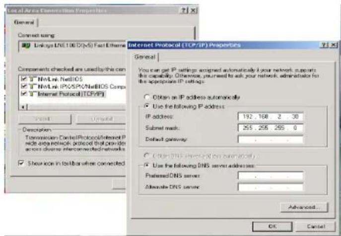
Local Area Connection Properties General Connect using: Linkless LNE100TX(x5) Fast Ethernet Components checked are used by this con NWLink NetBIOS NWLink IPX/SPX/NetBIOS Comp Internet Protocol(TCP/IP) Show Update Description Transmission ControlIPProtocol/Internet P node area network protocol that provides across diverse interconnected networks Show icon in toolbar when connected Internet Protocol (TCP/IP) Properties General You can get IP settings: assigned automatically for your network, supports the capability. Otherwise, you need to ask your network administrator for the appropriate IP settings. Obtain an IP address automatically Use the following IP address: IP address: 192, 168, 2, 30 Submit mask: 255, 255, 255, 0 Default gateway Obtain DNS server addresses Use the following DNS server addresses: Preferred DNS server Alternate DNS server Advanced... OK Cancel

Step 3: Open the web browser (like IE...), and go to 192.168.2.1 Then you will see the login screen.
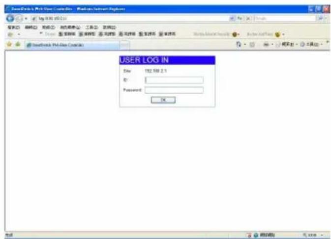
User Log IN Date: 182.10.2.1 Password: OK

ID and the password: admin

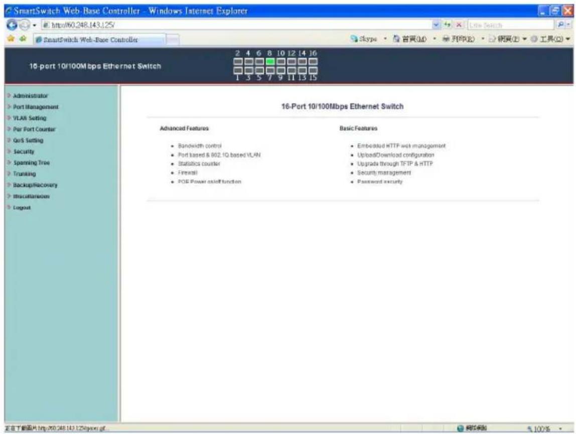
Step 4: After the authentication procedure, the home page shows up. Select one of the configurations by clicking the icon.

  • Administrator
  • Port Management
  • VLAN Setting
  • Per Port Counter
  • QoS Setting
  • Security
  • Spanning Tree
  • Trunking
  • Backup/Recovery
  • Miscellaneous
  • Logout

SmartSwitch Web-Base Controller - Windows Internet Explorer http://60.248.143.125/ SmartSwitch Web-Base Controller Skype · 首頁(M) · 列印(P) · 網頁(E) · 工具(T) 16-port 10/100Mbps Ethernet Switch 2 4 6 8 10 12 14 16 1 3 5 7 9 11 13 15 Administrator Port Management VLAN Setting Par Port Counter QoS Setting Security Spanning Tree Trunking Backup/Recovery Miscellaneous Logout 16-Port 10/100Mbps Ethernet Switch Advanced Features • Bandwidth control • Port based & 802.1Q based VLAN • Statistics counter • Firewall • POE Power asoff function Basic Features • Embedded HTTP web management • UploadDownload configuration • Upgrade through TFTP & HTTP • Security management • Password security 正在下载图片 http://60.248.143.125@jpor.gf.

Administrator: Authentication Configuration
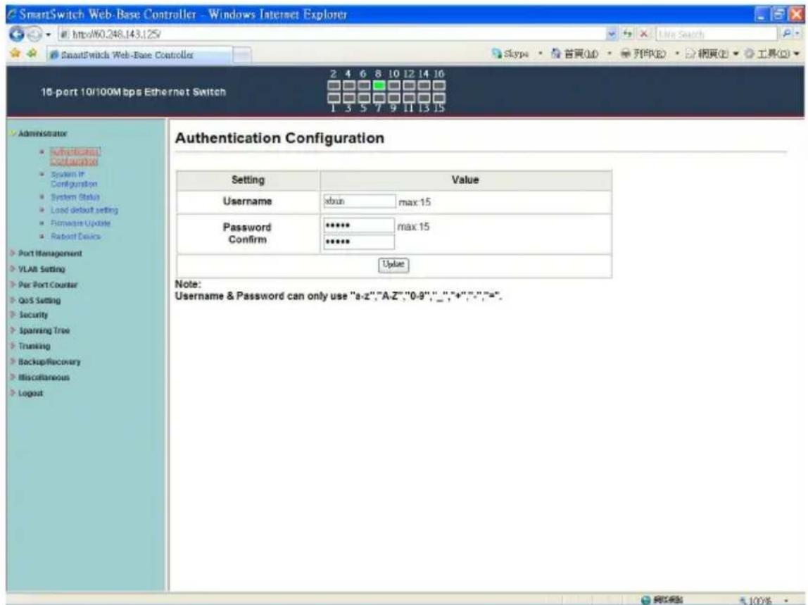
SmartSwitch Web-Base Controller - Windows Internet Explorer http://60.248.143.125 SmartSwitchs Web-Base Controller 16-port 10/100Mbps Ethernet Switch 2 4 6 8 10 12 14 16 1 5 5 7 9 11 13 15 Administrator Authentication Confusion System IP Configuration System Status Load default setting Hardware Update Robot Device Port Management VLAN Setting Par Port Counter QoS Setting Security Spanning Tree Trunking BackupRecovery Miscellaneous Logout Authentication Configuration Setting Value Username xbun_max:15 Password ***** max:15 Confirm *****_ Value Note: Username & Password can only use "a-z","A-Z","0-9",","+"",","=". 100%

  1. Change the user name and the password.
  2. Click "Update" to confirm the new change.

Now, you can use the new user name and the password.

Administrator: System IP Configuration
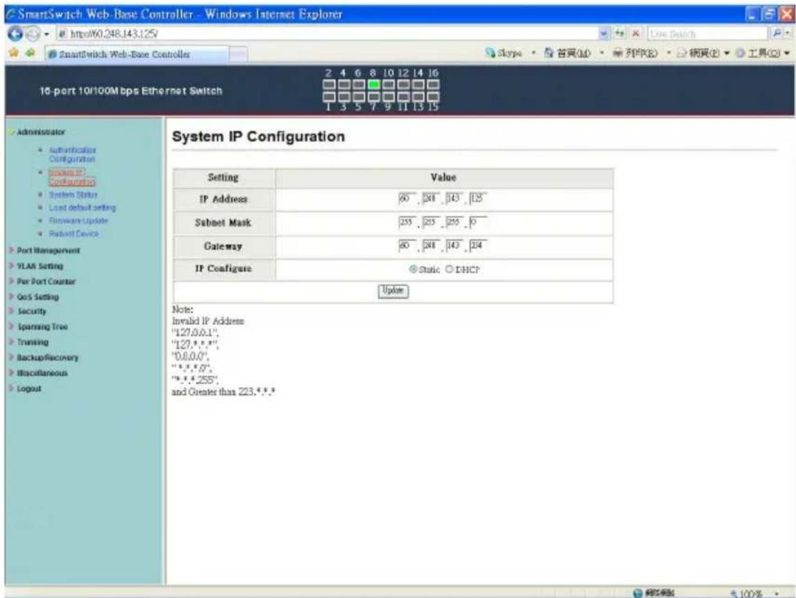
SmartSwitch Web-Base Controller - Windows Internet Explorer http://60.248.143.125/ SmartSwitch Web-Base Controller 10-port 10/100Mbps Ethernet Switch 2 4 6 8 10 12 14 16 1 3 5 7 9 11 13 15 Administrator • Authentication Configuration • Open IP Configuration • System Status • Load default setting • Firmware Update • Robot Device Port Management VLAN Setting Per Port Counter QoS Setting Security Spanning Tree Transing Backup/Recovery Miscellaneous Logout System IP Configuration Setting Value IP Address 60 ,241 ,143 ,125 Subnet Mask 255 ,255 ,255 ,0 Gateway 60 ,241 ,143 ,124 IP Configure Static ○ DHCP Update Note: Invalid IP Address "127.0.0.1", "127.0.0.1", "0.0.0.0", "*.0.0.0", "*.0.0.0", and Greater than 223.***

  1. Change the IP address: type the new IP address or select DHCP IP configuration.

  2. Click "Update" to confirm the new change. "Setting Process OK!!" will be shown on the screen.

Now, the setting of "System IP Configuration" is finished.

Administrator: System Status
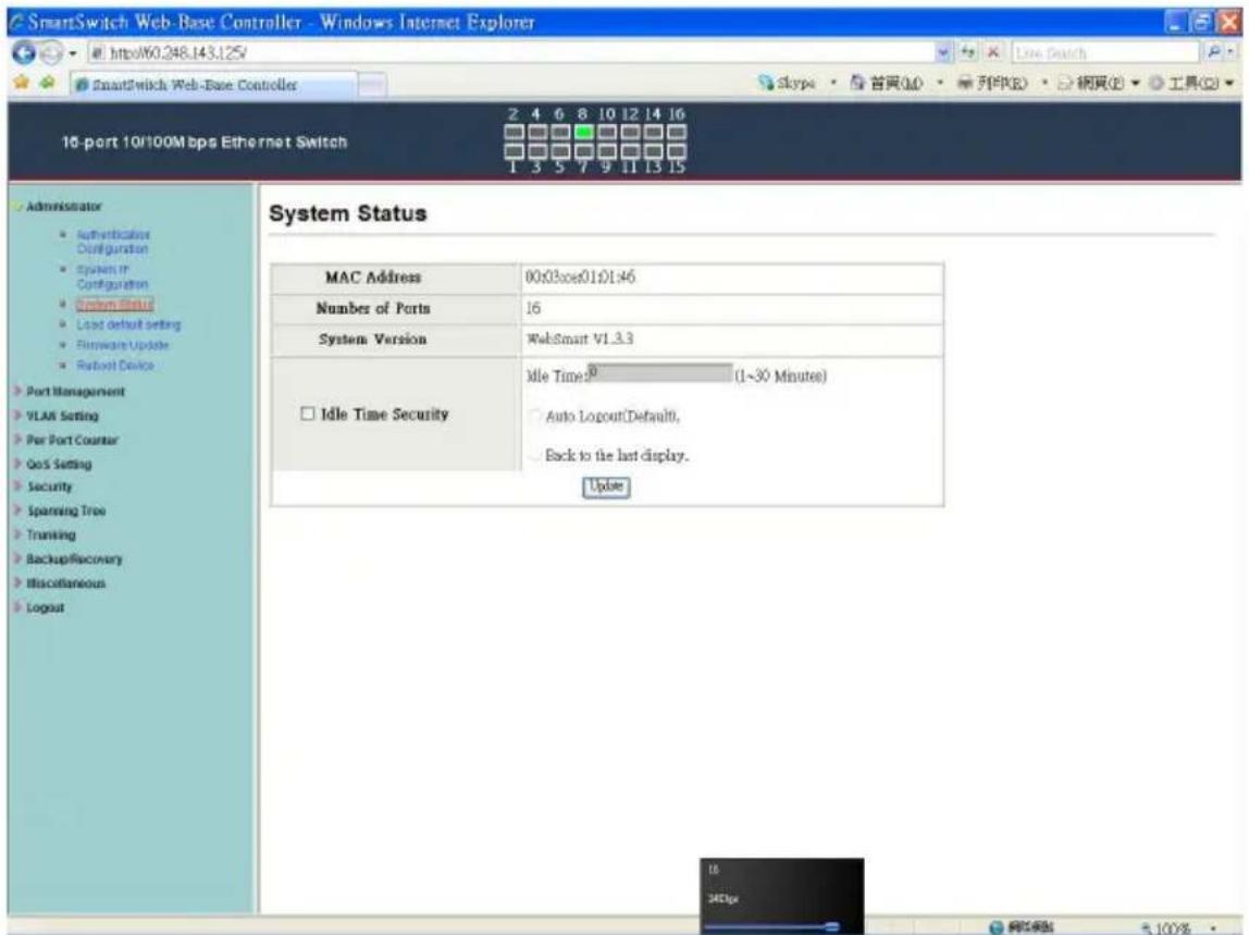
SmartSwitch Web-Base Controller - Windows Internet Explorer http://60.248.143.125/ SmartSwitch Web-Base Controller 16-port 10/100Mbps Ethernet Switch 2 4 6 8 10 12 14 16 Skype · 首頁(M) · 列印(R) · 網頁(B) · 工具(O) 1 3 5 7 9 11 13 15 Administrator • Authentication Configuration • System In Configuration • System Status • Load default setting • Firmware Update • Robust Device Port Management VLAN Setting Per Port Counter QoS Setting Security Spanning Tree Trunking BackupRecovery Miscellaneous Logout System Status MAC Address 00x03ces01:01:46 Number of Ports 16 System Version WebSmart V1.3.3 Idle Time:9 (1~30 Minutes) □ Idle Time Security Auto LogoutDefault0, Back to the last display. Update 18 241px 网络链接 +100%

MAC address and system version will be shown on the screen.

  1. Change the new comment of this switch by typing the new comment.
  2. Click "Update" to confirm the new change.

Now, the setting of “System Status” is finished.

Administrator: Load Default Setting
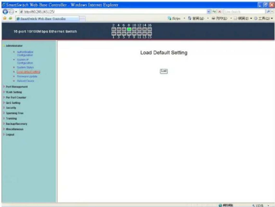
SmartSwitch Web-Base Controller - Windows Internet Explorer http://60.248.143.125/ SmartSwitch Web-Base Controller 16-port 10/100M bps Ethernet Switch 2 4 6 8 10 12 14 16 1 3 5 7 9 11 13 15 Administrator • Authentication Configuration • System In Configuration • System Status • Load default setting • Software Update • Rabbit Device Port Management VLAN Setting Per Port Counter GoS Setting Security Spanning Tree Trucking Backup/Recovery Miscellaneous Logout Load Default Setting Load 100%

  1. Click "Load" to back to the factory default setting.

**Note: Recover switch default setting excluding the IP address, User name and Password.

Now, the default is loaded.

Administrator: Firmware Update
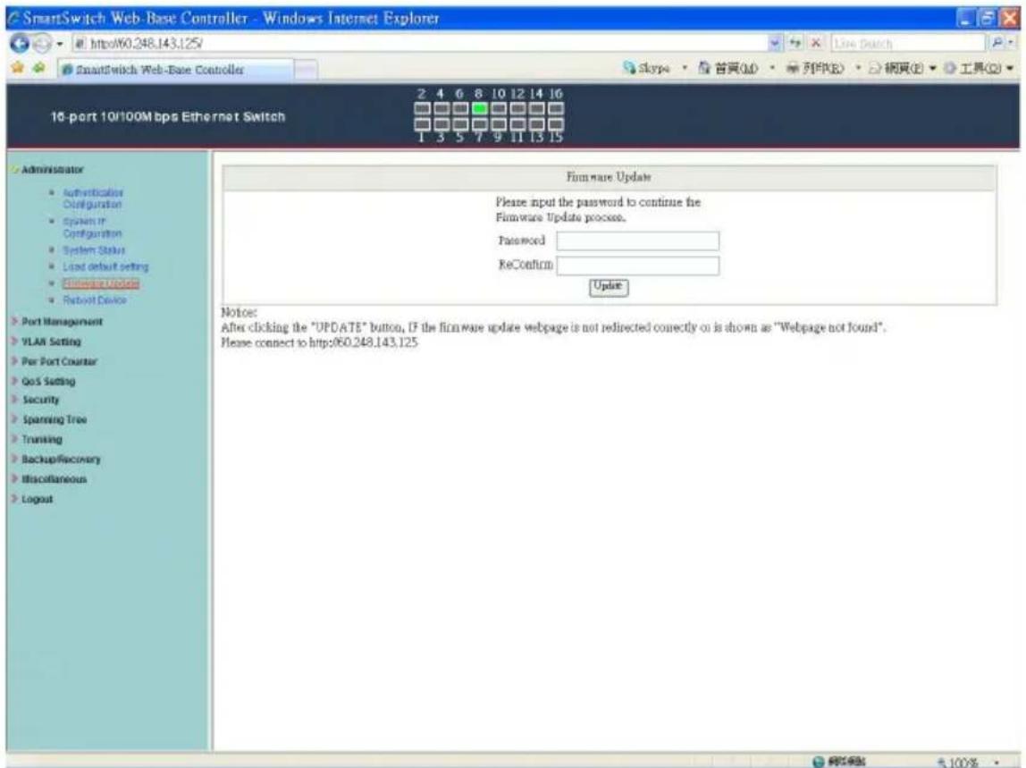
SmartSwitch Web-Base Controller - Windows Internet Explorer http://60.248.143.125 SmartSwitch Web-Base Controller 16-port 10/100Mbps Ethernet Switch 2 4 6 8 10 12 14 16 1 3 5 7 9 11 13 15 Administrator • Authentication Configuration • System in Configuration • System Status • Load default setting • Firmware Update • Reboot Device Port Management VLAN Setting Per Port Counter QoS Setting Security Spanning Tree Trunking Backup/Recovery Miscellaneous Logout Firmware Update Please input the password to continue the Firmware Update process. Password ReConfirm Update Notes: After clicking the "UPDATE" button, IF the firmware update webpage is not redirected correctly on is shown as "Webpage not found". Please connect to http://60.248.143.125

Follow the instruction on the screen to update the new firmware.

Please contact with your sales agents to get the latest firmware information.

Administrator: Reboot Device
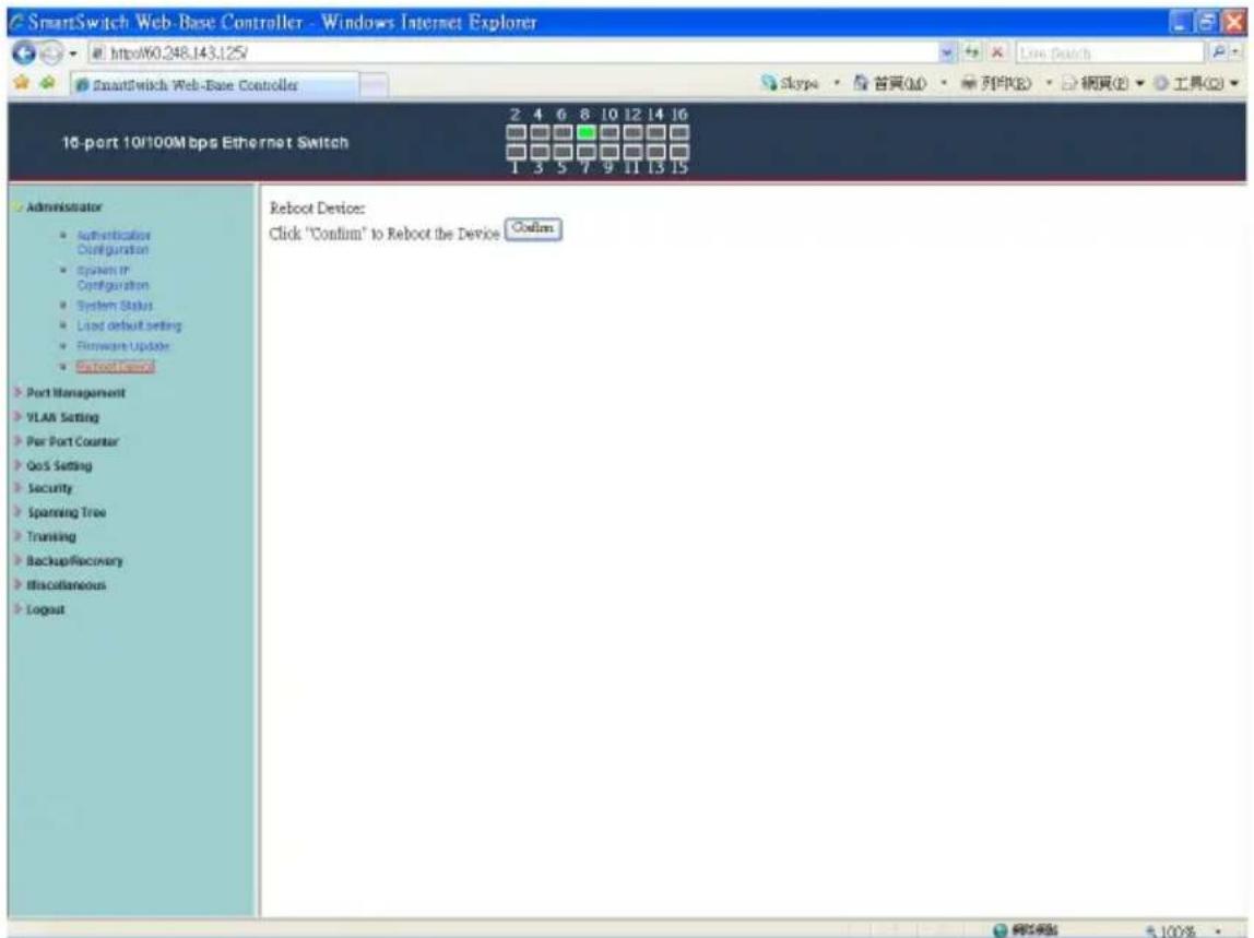
SmartSwitch Web-Base Controller - Windows Internet Explorer http://60.248.143.125/ SmartSwitch Web-Base Controller 10-port 10/100Mbps Ethernet Switch Administrator • Authentication Configuration • System In Configuration • System Status • Load default setting • Firmware Update • Retrout/Remed Port Management VLAN Setting Per Port Counter QoS Setting Security Spanning Tree Trusting Backup/Recovery Miscellaneous Logout Reboot Device: Click "Confirm" to Reboot the Device Codim

  1. Click "Confirm" to reboot the device.

Now, the setting of "Reboot Device" is finished.

Port Management: Port Configuration
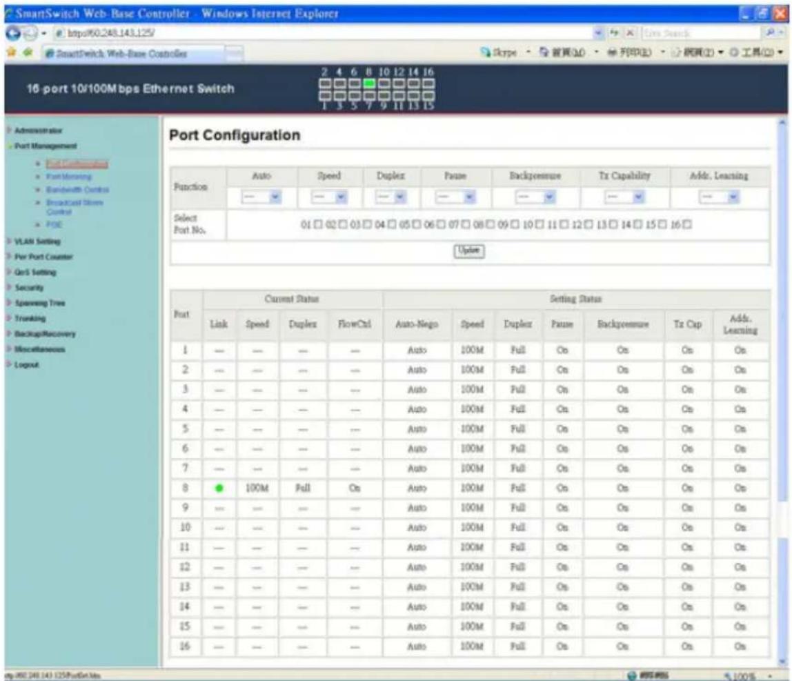
SmartSwitch Web-Base Controller - Windows Internet Explorer http://60.248.143.125/ SmartSwitch Web-Base Controller 16 port 10/100Mbps Ethernet Switch Port Configuration Function Auto Speed Duplex Pause Backpensure Tx Capability Addr. Learning Select Port No. 01 □ 02 □ 03 □ 04 □ 05 □ 06 □ 07 □ 08 □ 09 □ 10 □ 11 □ 12 □ 13 □ 14 □ 15 □ 16 □ Update Port Current Status Setting Status Link Speed Duplex FlowCtrl Auto-Nego Speed Duplex Pause Backpensure Tx Cap Addr. Learning 1 — — — — Auto 100M Full On On On On 2 — — — — Auto 100M Full On On On On 3 — — — — Auto 100M Full On On On On 4 — — — — Auto 100M Full On On On On 5 — — — — Auto 100M Full On On On On 6 — — — — Auto 100M Full On On On On 7 — — — — Auto 100M Full On On On On 8 ● 100M Full On Auto 100M Full On On On On 9 — — — — Auto 100M Full On On On On 10 — — — — Auto 100M Full On On On On 11 — — — — Auto 100M Full On On On On 12 — — — — Auto 100M Full On On On On 13 — — — — Auto 100M Full On On On On 14 — — — — Auto 100M Full On On On On 15 — — — — Auto 100M Full On On On On 16 — — — — Auto 100M Full On On On e.g.88.248.143.125/FullScan.htm

Select the "Port No." - configure the mode below:

  1. “Auto-Nego” - enable/disable Auto-Negotiation.
  2. “Speed” - 10M or 100M mode for the selected port.
  3. "Duplex" - Full or Half-Duplex mode for the selected port.
  4. “Pause” - enable/disable for the selected port.
  5. "Backpressure" - enable/disable for the selected port.
  6. “Tx Cap (Capability)” - enable/disable for the selected port.
  7. "Addr. Learning" - enable/disable for the selected port.

Now, the setting of "Port Configuration" is finished.

Port Management: Port Mirroring
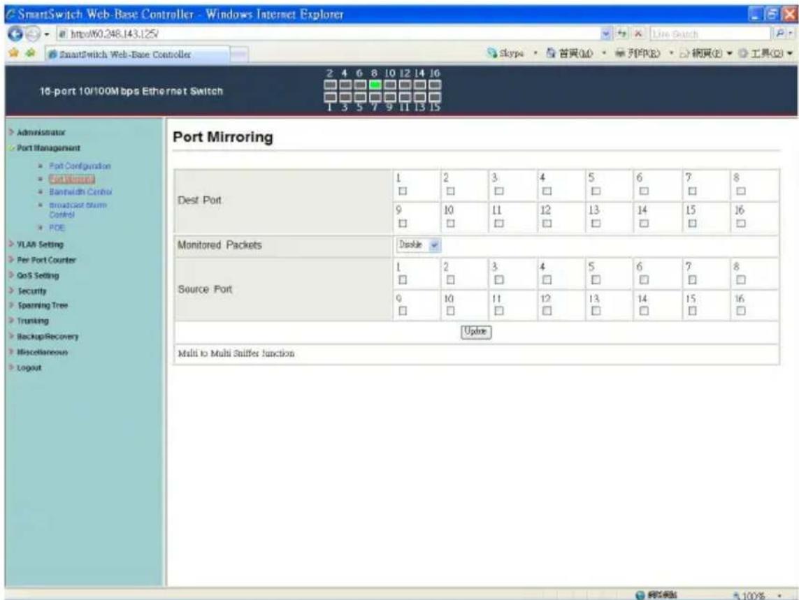
SmartSwitch Web-Base Controller - Windows Internet Explorer http://60.248.143.125 SmartSwitch Web-Base Controller 10-port 10/100Mbps Ethernet Switch 2 4 6 8 10 12 14 16 1 3 5 7 9 11 13 15 Port Mirroring Dest Port 1 2 3 4 5 6 7 8 □ □ □ □ □ □ □ □ □ □ □ □ □ □ □ □ □ □ □ □ □ □ □ □ □ □ □ □ □ □ □ □ □ □ □ □ □ □ □ □ □ □ □ □ □ □ □ □ □ □ VLAN Setting Per Port Counter QoS Setting Security Spanning Tree Trunking BackupRecovery Miscellaneous Logout Monitored Packets Disable Source Port 1 2 3 4 5 6 7 8 □ □ □ □ □ □ □ □ □ □ □ □ □ □ □ □ □ □ □ □ □ □ □ □ □ □ □ □ □ □ □ □ □ □ □ □ □ □ □ □ □ (N) Multi to Multi Sniffer Junction

Port Mirroring is used to mirror traffic, RX, TX or TX&RX, from Source port to Destination port for analysis.

  1. Select the Destination port: you can choose port 1 to port 16
  2. Select the Source port: by clicking the checking box of the port.
  3. Click "Update" to save the setting.

Now, the setting of "Port Mirroring" is finished.

Port Management: Bandwidth Control
SmartSwitch Web-Base Controller - Windows Internet Explorer http://60.248.143.125/ SmartSwitch Web-Base Controller 10-port 10/100Mbps Ethernet Switch 2 4 6 8 10 12 14 16 1 3 5 7 9 11 13 15 Administrator Port Management • Port Configuration • Port Winning • Network Control • Broadcast Storm Control • POE • VLAN Setting • Per Port Counter • GoS Setting • Security • Spanning Tree • Tranking • Backup Recovery • Miscellaneous • Logout Bandwidth Control Port No Tx Rate Value Rx Rate Value 01 Bandwidth = __X resolution. (0~19/195/255) 0: Full speed. 1~19/195/255; Specified bandwidth. Resolution Low Low:32Kbps (1).Rate value: 1~255. High:512Kbps (1).When link speed is 10M and the resolution is 512Kbps, the Rate value should be 1~19. (2).When link speed is 100M and the resolution is 512Kbps, the Rate value should be 1~195. All ports use the same bandwidth resolution. Update LoadDefault If the link speed of selected port is lower than the rate that you setting, this system will use the value of link speed as your setting site. Port No Tx Rate(Kbps) Rx Rate(Kbps) Link Speed Port No Tx Rate(Kbps) Rx Rate(Kbps) Link Speed 1 Full Speed Full Speed - 9 Full Speed Full Speed - 2 Full Speed Full Speed - 10 Full Speed Full Speed - 3 Full Speed Full Speed - 11 Full Speed Full Speed - 4 Full Speed Full Speed - 12 Full Speed Full Speed - 5 Full Speed Full Speed - 13 Full Speed Full Speed - 6 Full Speed Full Speed - 14 Full Speed Full Speed - 7 Full Speed Full Speed - 15 Full Speed Full Speed - 8 Full Speed Full Speed 100M 16 Full Speed Full Speed - http://60.248.143.125/DataRate.htm

  1. Select the "Port No.": you can choose port 1 to port 16
  2. “TX Rate Value”: set the transmission rate of the selected port. (0:Full speed; 1\~255:Specified bandwidth.)
  3. “RX Rate Value”: set the receiving rate of the selected port. (0: Full speed; 1\~255: Specified bandwidth.)
  4. “Resolution”: Low: 32 kbps / High: 512 kbps
  5. Click "Update" to confirm the setting or "LoadDefault".

Now, the setting of “Bandwidth Control” is finished.

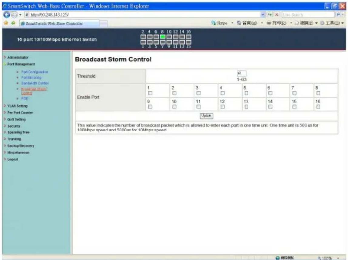
Port Management: Broadcast Storm Control
SmartSwitch Web-Base Controller - Windows Internet Explorer http://60.248.143.125/ SmartSwitch Web-Base Controller 16-port 10/100Mbps Ethernet Switch 2 4 6 8 10 12 14 16 Skype · 首頁(M) · 列印(R) · 網頁(B) · 工具(G) Administrator Port Management Port Configuration PortSamsung Bandwidth Control Broadcast Storm Control POE VLAN Setting Per Port Counter GoS Setting Security Spinning Tree Tranking BackupRecovery Miscellaneous Logout Broadcast Storm Control Threshold: 61 1~63 Enable Port 1 2 3 4 5 6 7 8 □ □ □ □ □ □ □ □ □ 9 10 11 12 13 14 15 16 □ □ □ □ □ □ □ □ Update This value indicates the number of broadcast packet which is allowed to enter each port in one time unit. One time unit is 500 us for 100Mbps speed and 500us for 10Mbps speed

  1. "Threshold" - Set the threshold from 1\~63.
  2. "Enable Port" - per port to define the status of broadcast packets.
  3. Click "Update" to confirm the setting.

Now, the setting of “Broadcast Storm Control” is finished.

Port Management: PoE Configuration
SmartSwitch Web-Base Controller - Windows Internet Explorer http://60.248.143.125/ SmartSwitch Web-Base Controller 16 port 10/100M bps Ethernet Switch 2 4 6 8 10 12 14 16 1 3 5 7 9 11 13 15 Administrator Port Management Port Configuration Port Worsing Bandwidth Control broadcast system Control VLAIR Setting Per Port Counter OnS Setting Security Spinning Tree Trunking Backup/Recovery Miscellaneous Logout POE Configuration Port 01 02 03 04 05 06 07 08 Enable ☑ ☑ ☑ ☑ ☑ ☑ ☑ ☑ PSE Current No Load No Load No Load No Load No Load No Load No Load No Load No Load Minimum Output Power — — — — — — — — — POE Class — — — — — — — — — Port 00 10 11 12 13 14 15 16 Enable ☑ ☑ ☑ ☑ ☑ ☑ ☑ ☑ PSE Current No Load No Load No Load No Load No Load No Load No Load No Load No Load Minimum Output Power — — — — — — — — — POE Class — — — — — — — — — Update: Update: Update the power control function. Enable®:Power On Enable™:Power Off

Remote access and monitor the attached PD (Powered Device) status by using Enable/Disable function.

  1. Enable: POE of the port is able to supply power to the attached PD (Powered Device)
  2. PSE Current & Minimum Output Power: The status of the port current and minimum output power.
  3. POE class: each POE port will detect the class of the attached PD (Powered Device)
  4. Click "Update" to confirm and finish the setting.

Now, the setting of "PoE Configuration" is finished.

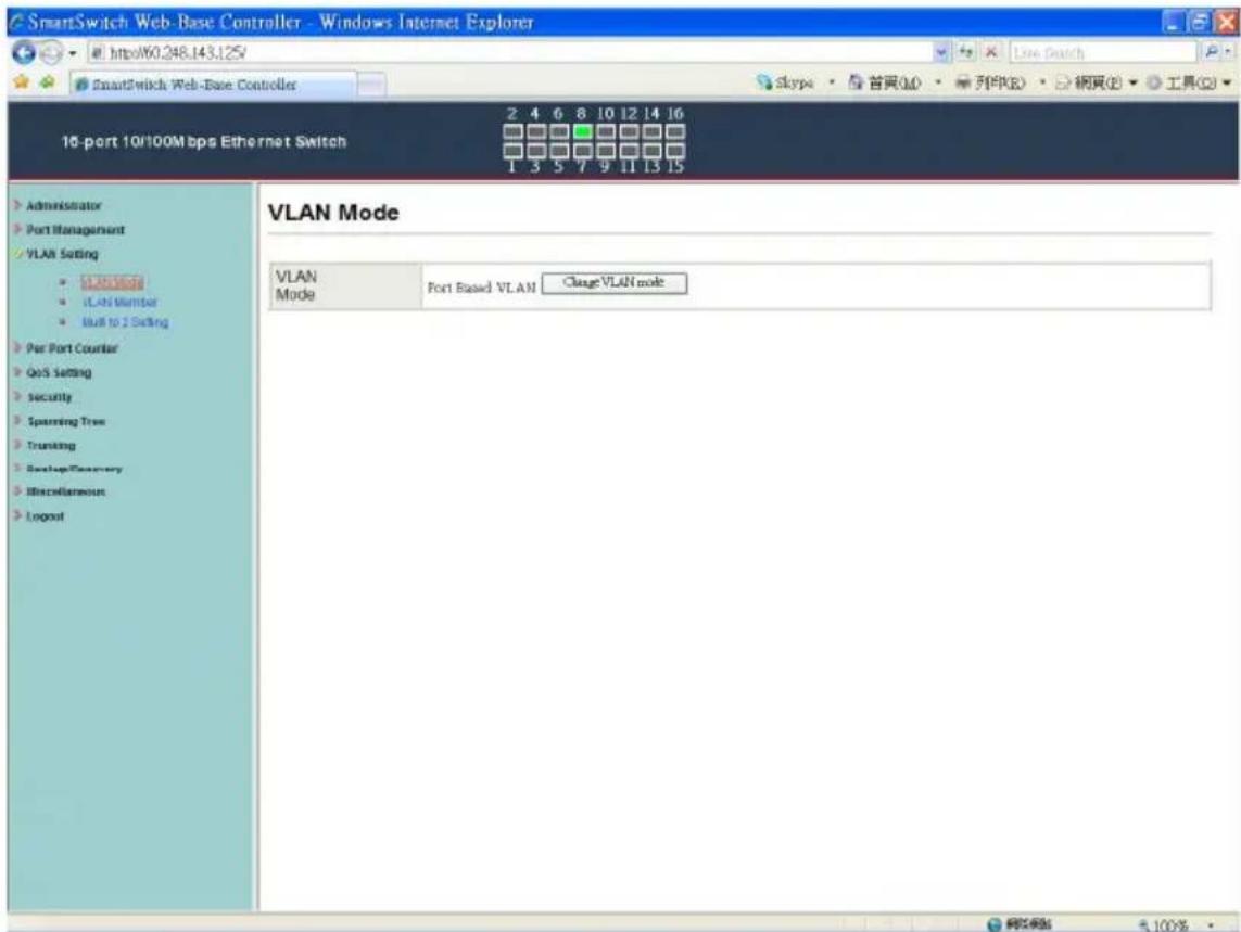
VLAN Setting: VLAN Mode
SmartSwitch Web-Base Controller - Windows Internet Explorer http://60.248.143.125 SmartSwitch Web-Base Controller 10-port 10/100Mbps Ethernet Switch VLAN Mode VLAN Mode Port Based VLAN ChangeVLAN mode Administrator Port Management VLAN Setting • Modified • VLAN Member • Mail to 2 Setting Par Port Counter QoS Setting Security Spanning Tree Trunting Backup/Inventory Miscellaneous Login 5.100%

There are two VLAN modes : Port Based VLAN and Tagged VLAN.

Click "Change VLAN mode" to select the mode.

**If the Port Based VLAN function is enabled, Multi to 2 setting and tag Based VLAN will be disabled automatically.

Now, the setting of "VLAN Mode" is finished.

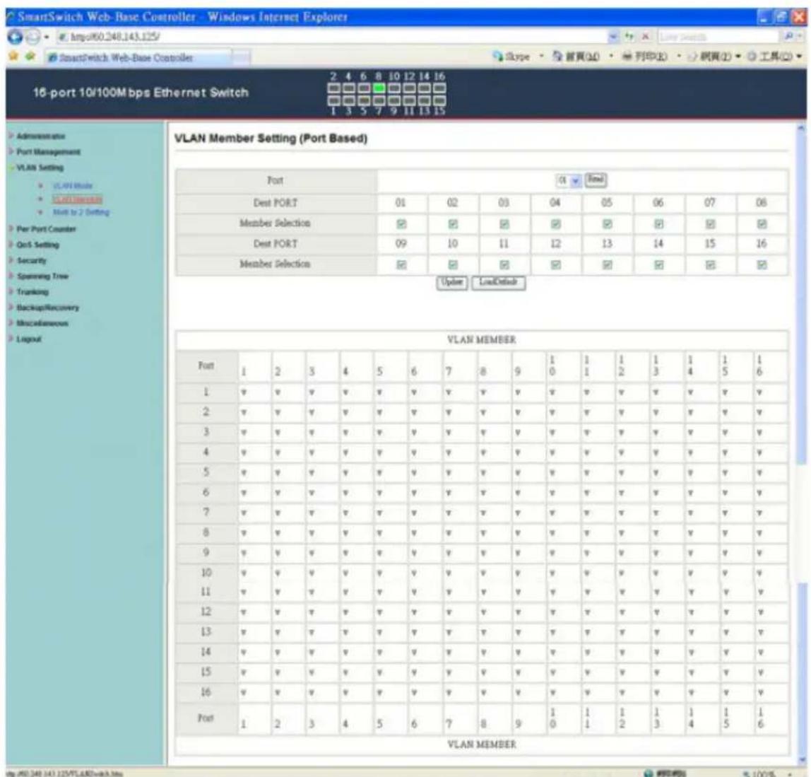
VLAN Setting: VLAN Member Setting (Port Based)
SmartSwitch Web-Base Controller - Windows Internet Explorer http://60.248.143.125/ SmartSwitch Web-Base Controller 16-port 10/100M bps Ethernet Switch 2 4 6 8 10 12 14 16 1 3 5 7 9 11 13 15 VLAN Member Setting (Port Based) Port Dest PORT Member Selection Dest PORT Member Selection 01 02 03 04 05 06 07 08 09 10 11 12 13 14 15 16 Update LoadDebug VLAN MEMBER Port 1 2 3 4 5 6 7 8 9 1 1 1 1 1 1 1 1 v v v v v v v v v v v v v v v v v 2 v v v v v v v v v v v v v v v v v v v 3 v v v v v v v v v v v v v v v v v v 4 v v v v v v v v v v v v v v v v v v 5 v v v v v v v v v v v v v v v v v 6 v v v v v v v v v v v v v v v 7 v v v v v v v v v v v v v 8 v v v v v v v v v v v v v 9 v v v v v v v v v v v v 10 v v v v v v wv wv wv wv wv wv 11 wv wv wv wv wv wv wv wv 12 wv wv wv wv wv wv wv wv wv 13 wv wv wv wv wv wv wv wv 14 wv wv wv wv wv wv wv wv 15 wv wv wv wv wv wv wv wv 16 wv wv wv wv wv wv wv wv Port 1 2 3 4 5 6 7 8 9 1 1 1 1 1 1 VLAN MEMBER http://60.248.143.125/TLA/BXbsw.hns

You can select a port group.

  1. Click the port numbers: which you want to put them into the selected VLAN group.
  2. Click "Update" to confirm and finish the setting.
  3. Click "LoadDefault" to back to the original factory setting.

Now, the setting of "VLAN Mode" is finished.

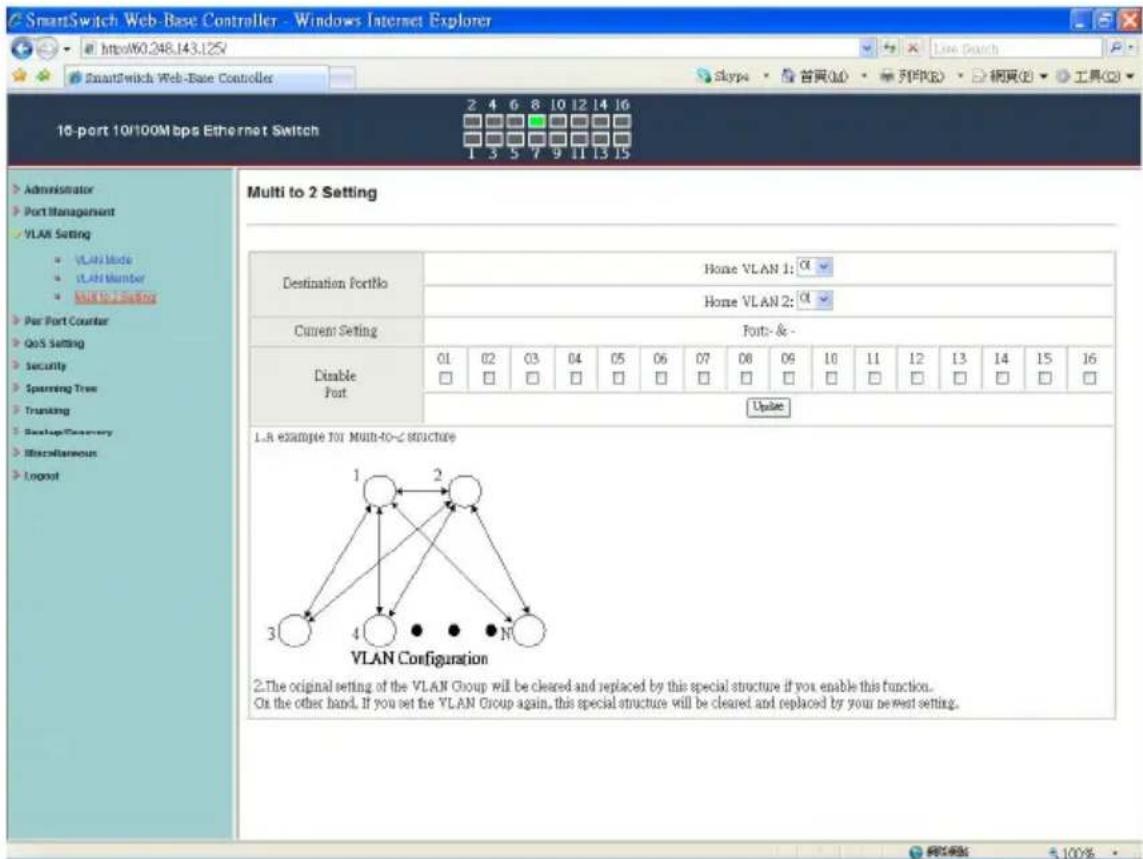
VLAN Setting: Multi to 2 Setting
SmartSwitch Web-Base Controller - Windows Internet Explorer http://60.248.143.125 SmartSwitch Web-Base Controller 10-port 10/100Mbps Ethernet Switch Multi to 2 Setting Destination Portfolio Home VLAN 1: Home VLAN 2: Current Setting Fonts- & - Disable Port 01 02 03 04 05 06 07 08 09 10 11 12 13 14 15 16 □ □ □ □ □ □ □ □ □ □ □ □ □ □ □ □ □ □ □ □ □ □ □ □ □ □ □ □ □ □ □ □ □ □ □ □ □ □ □ □ □ □ □ □ □ □ □ □ □ □ □ ▢ Update L.A example for Multi-to-2 Structure VLAN Configuration 2.The original setting of the VLAN Group will be cleared and replaced by this special structure if you enable this function. On the other hand, If you set the VLAN Group again, this special structure will be cleared and replaced by your newest setting.

This is a special design for easily setting the switch VLAN into "VLAN Per Port".

  1. Choose "Destination Port No".
  2. Choose "Disable Port"
  3. "Disable Port" – choose the port which you don't want to use
  4. Click "Update" to confirm and finish the setting.

After this setting, all ports can only connect to destination ports.

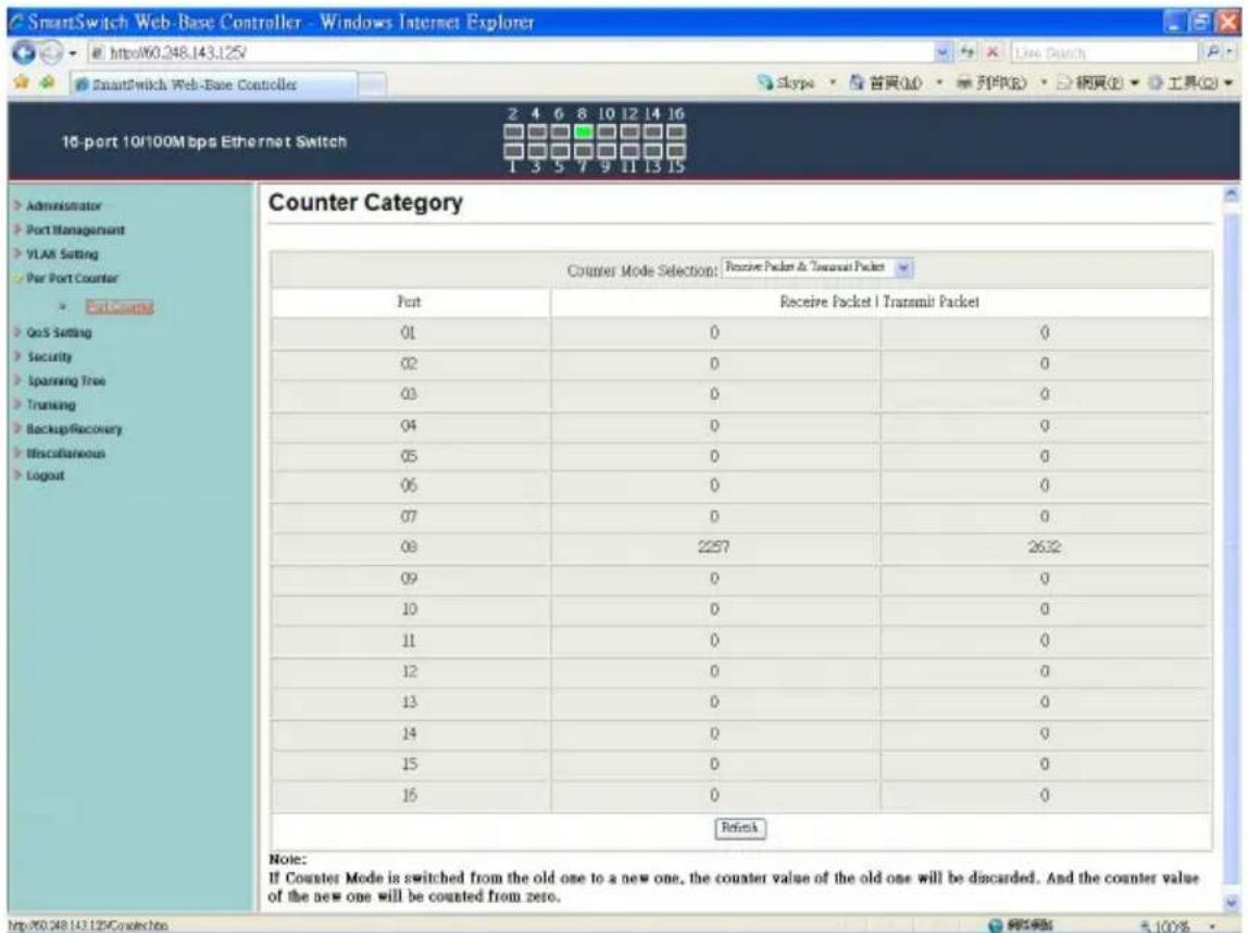
Per Port Counter: Counter Category
SmartSwitch Web-Base Controller - Windows Internet Explorer http://60.248.143.125/ SmartSwitch Web-Base Controllers 16-port 10/100Mbps Ethernet Switch Counter Category Counter Mode Selection: Receive Packet & Transmit Packet Port Receive Packet | Transmit Packet 01 02 03 04 05 06 07 08 09 10 11 12 13 14 15 16 2 4 6 8 10 12 14 16 Skype · 首頁(M) · 列印(R) · 網頁(P) · 工具(G) Refinek Note: If Counter Mode is switched from the old one to a new one, the counter value of the old one will be discarded. And the counter value of the new one will be counted from zero. http://60.248.143.125Conlection

You can read the transmitting and receiving packet of the connecting port.

Click "Refresh" or "Clear" the data.

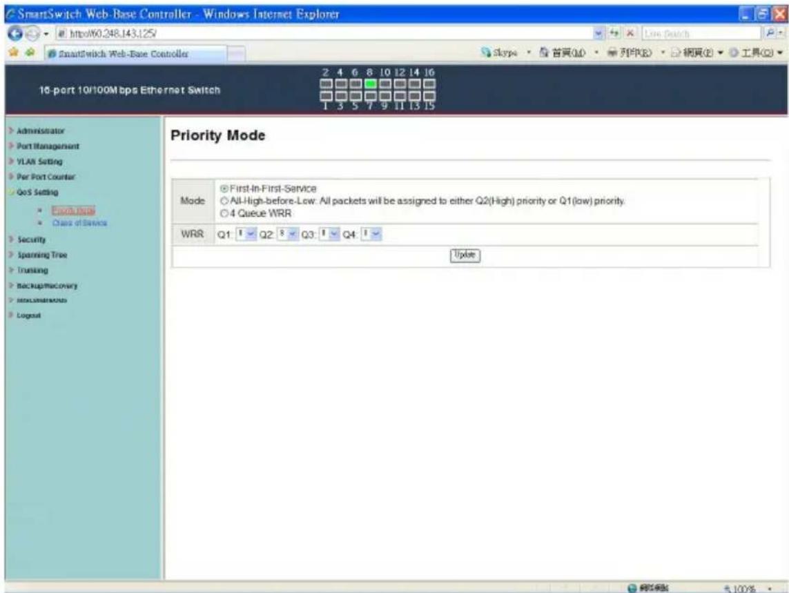
QoS Setting: Priority Mode
SmartSwitch Web-Base Controller - Windows Internet Explorer http://60.248.143.125/ SmartSwitch Web-Base Controller 10-port 10/100Mbps Ethernet Switch 2 4 6 8 10 12 14 16 Skype · 首頁(M) · 列印(R) · 網頁(P) · 工具(Q) Priority Mode Mode ○ First-In-First-Service ○ All-High-before-Low: All packets will be assigned to either Q2(High) priority or Q1(low) priority. ○ 4 Queue WRR WRR Q1: 1 Q2: 8 Q3: 1 Q4: 1 Update Administrator Port Management VLAN Setting Per Port Counter QoS Setting • Security • Spanning Tree • Trunking • Backup/Macrony • Intro/Instructions • Logout

There are three Priority Modes to select.

  1. “First-in-First-Out” - the first receiving packet will be firstly transmitted.
  2. “All-High-before-Low” – All packets will be assigned to either Q2(high) priority queue or Q1(low) priority queue.
  3. “4 Queue WRR (Weight-Round-Robin)” - set the ratio of the transmitting packet for the low priority to high priority.
  4. Click "Update" to confirm and finish the setting.

QoS Setting: Class of Service
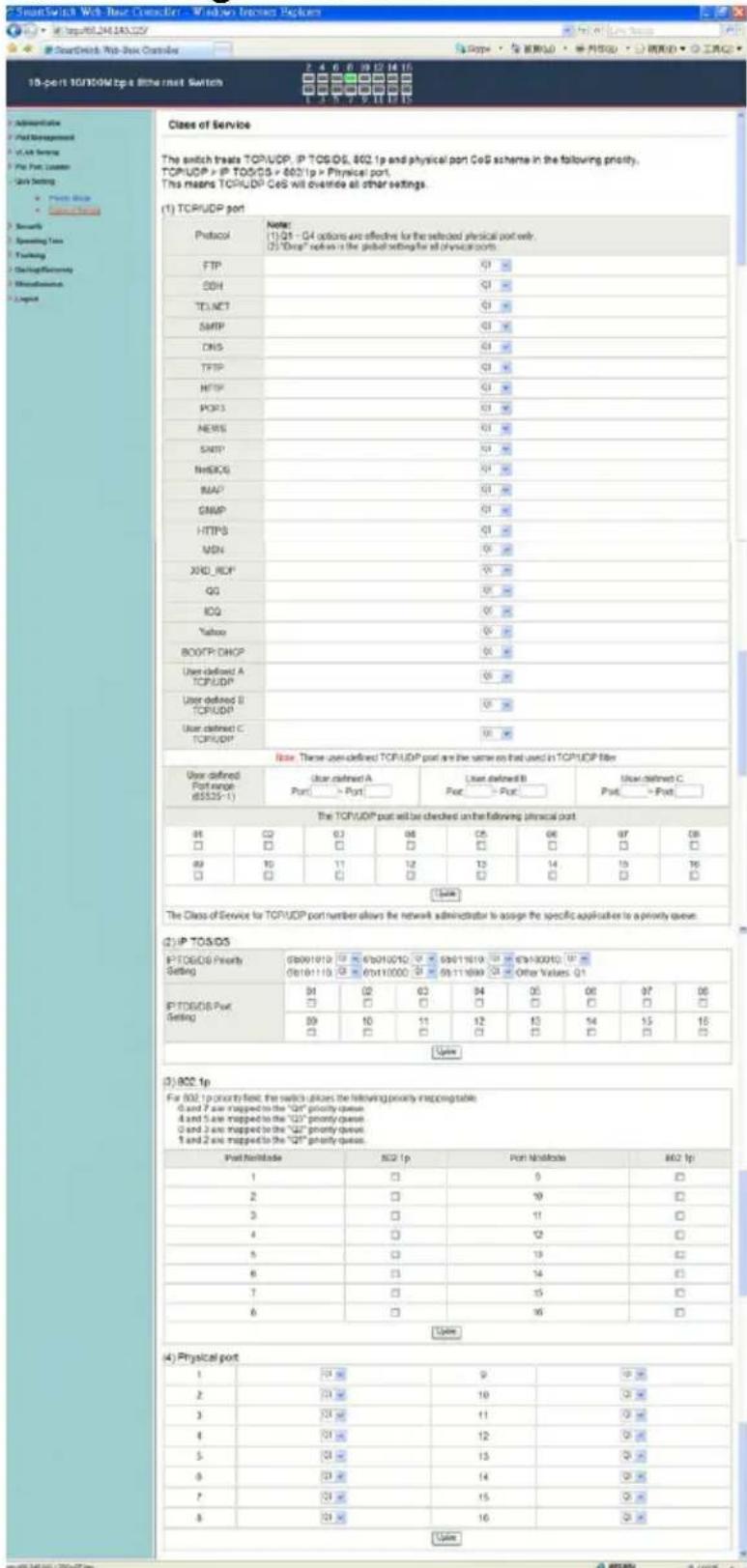
Class of Service The switch treats TCP/UDP, IP TOS/OS, 802.1p and physical port CoS scheme in the following priority. TCP/UDP > IP TOS/OS > 802.1p > Physical port. This means TCP/UDP CoS will override all other settings. (1) TCP/UDP port Protocol Name: (1) Q1 - Q4 options are effective for the selected physical port only. (2) "Drive" options is the global setting for all physical ports. FTP Q1 SSH Q1 TELNET Q1 SMTP Q1 DNS Q1 TFIP Q1 HTTP Q1 IPOPS Q1 NEWS Q1 SMTP Q1 NHEORG Q1 MAP Q1 GMP Q1 HTTPS Q1 MSN Q1 XRD_ROF Q1 QQ Q1 QQ Yahoo Q1 BOOTP_DHOP Q1 User defined A TCP/UDP Q1 User defined B TCP/UDP Q1 User defined C TCP/UDP Note: These user-defined TCP/UDP port are the same on that used in TCP/UDP file: User-defined Port endpoint (85529-1) User-defined A Port > Port User defined B Port > Port User-defined C Port > Port The TCP/UDP port will be checked on the following physical port: 08 CQ 03 08 C5 06 07 08 09 T0 11 12 T3 14 15 T6 09 T0 C0 C1 C2 C3 Other Values: Q1 01 02 03 04 05 06 07 08 09 10 11 12 13 14 15 16 09 10 C0 C1 C2 C3 C4 C5 C6 C7 09/10/20/20 09/11/20/20 09/12/20/20 09/13/20/20 09/14/20/20 09/15/20/20 09/16/20/20 09/17/20/20 09/18/20/20 09/19/20/20 09/20/20/20 09/21/20/20 09/22/20/20 09/23/20/20 09/24/20/20 09/25/20/20 09/26/20/20 09/27/20/20 09/28/20/20 09/29/20/20 09/30/20/20 09/31/20/20 09/32/20/20 09/33/20/20 09/34/20/20 09/35/20/20 09/36/20/20 09/37/20/20 09/38/20/20 09/39/20/20 09/40/20/20 09/41/20/20 09/42/20/20 09/43/20/20 09/44/20/20 09/45/20/20 09/46/20/20 09/47/20/20 09/48/20/20 09/49/20/20 09 / ( ) IP TOSOIS Priority Setting: IP TOSOIS Port Setting: IP TOSOIS Port Setting: IP TOSOIS Port Setting: IP TOSOIS Port Setting: IP TOSOIS Port Setting: IP TOSOIS Port Setting: IP TOSOIS Port Setting: IP TOSOIS Port Setting: IP TOSOIS Port Setting: IP TOSOIS Port Setting: IP TOSOIS Port Setting: IP TOSOIS Port Setting: IP TOSOIS Port Setting: IP ITOOIS Port Setting: IP TOSOIS Port Setting: IP TOSOIS Port Setting: IP TOSOIS Port Setting: IP TOSOIS Port Setting: IP TOSOIS Port Setting: IP TOSOIS Port Setting: IP TOSOIS Port Setting: IP TOSOIS Port Setting: IP TOSOIS Port Setting: IP TOSOIS Port Setting: IP TOSOIS Port Setting: IP TOSOIS Port Settings: IP TOSOIS Port Settings: IP TOSOIS Port Settings: IP TOSOIS Port Settings: IP TOSOIS Port Settings: IP TOSOIS Port Settings: IP TOSOIS Port Settings: IP TOSOIS Port Settings: IP TOSOIS Port Settings: IP TOSOIS Port Settings: IP TOSOIS Port Settings: IP TOSOIS Port Settings: IP TOSOIS Port Settings: IP TOTOIS Port Settings: IP TOSOIS Port Settings: IP TOSOIS Port Settings: IP TOSOIS Port Settings: IP TOSOIS Port Settings: IP TOSOIS Port Settings: IP TOSOIS Port Settings: IP TOSOIS Port Settings: IP TOSOIS Port Settings: IP TOSOIS Port Settings: IP TOSOIS Port Settings: IP TOSOIS Port Settings: IP TOSOIS Port Setting: IP TOSOIS Port Setting: IP TOSOIS Port Setting: IP TOSOIS Port Setting: IP TOSOIS Port Setting: IP TOSOIS Port Setting: IP TOSOIS Port Setting: IP TOSOIS Port Setting: IP TOSOIS Port Setting: IP TOSOIS Port Setting: IP TOSOIS Port Setting: IP TOSOIS Port Setting: IP TOTOIS Port Setting: IP TOTOIS Port Setting: IP TOTOIS Port Setting: IP TOTOIS Port Setting: IP TOTOIS Port Setting:

You can set QoS mode of per port by different bases.

TCP/UDP > TP TPS/DS > 802.1P > Physical port

  1. “TCP/UDP Port” – Q1 \~ Q4 options are effective for the selected physical port only. “Drop” option is the global setting for all physical ports.

The packet queue will be transferred based on the number of “4 Queue WRR” on QoS Setting: Priority Mode.

**WRR -Q1/Q2/Q3/Q4

**“Drop” - packets will be dropped.

  1. “IP TOS/DS” – “Priority Setting”: Q1 \~ Q4; “IP TOS/DS Port Setting” - It means the packets with special IP will be firstly transmitted.

  2. “802.1p” – Priority mapping table as the screen shown.

  3. “Physical port” - you can select the port which you want to configure as Q1\~Q4 priority.

  4. Click “Update” to confirm and finish the setting.

Now, the setting of “Class of Service” is finished.

Security: MAC Address Filter
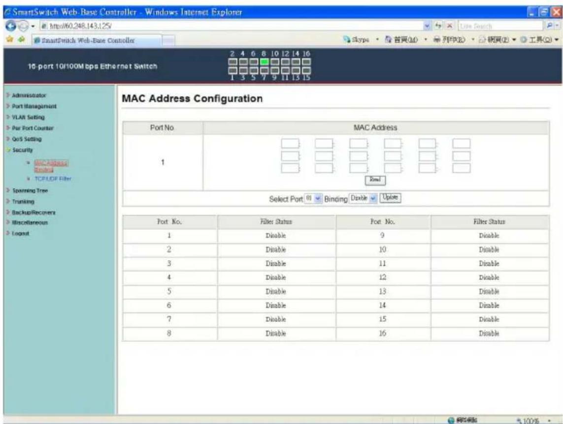
SmartSwitch Web-Base Controller - Windows Internet Explorer Http60.248.143.125 SmartSwitch Web-Base Controller Skype · 留灵(M) · 列(R) 16-port 10/100Mbps Ethernet Switch 2 4 6 8 10 12 14 16 1 3 5 7 9 11 13 15 Administrator Port Management VLAN Setting Port Port Counter QoS Setting Security InNExpress Sound TCPLOF Filter Spanning Tree Trunking BackupRecover Miscellaneous Logout MAC Address Configuration Port No. MAC Address 1 Total Select Port 01 Binding Disable Update Port No. Filter Status Port No. Filter Status 1 Disable 9 Disable 2 Disable 10 Disable 3 Disable 11 Disable 4 Disable 12 Disable 5 Disable 13 Disable 6 Disable 14 Disable 7 Disable 15 Disable 8 Disable 16 Disable

Set special MAC address to activate on the selected port

  1. Choose "Select Port" – port 1\~16
  2. “Binding” – “Enable”: allow the packet with the specified source MAC address to enter this port.
  3. Click "Update" to confirm and finish the setting.

Now, the setting of "MAC Address Filter" is finished.

Security: TCP\_UDP Filter Configuration
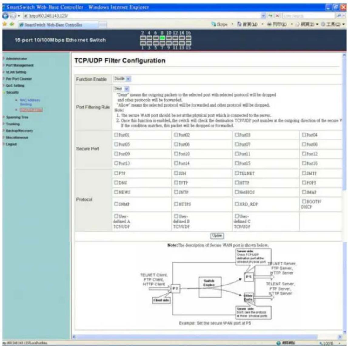
SmartSwitch Web-Base Controller - Windows Internet Explorer 15-port 10/100Mbps Ethernet Switch 2 4 6 8 10 12 14 16 1 3 5 7 9 11 13 15 Administrator Port Management VLAN Setting Per Port Counter QoS Setting Security MNC Address Banking PORTER Spinning Tree Trunking BackupRecovery Miscellaneous Logist TCP/UDP Filter Configuration Function Enable Double Port Filtering Rule Deep "Denay" means the outgoing packets to the selected port with selected protocol will be dropped and other protocols will be forwarded. "Allow" means the selected protocol will be forwarded and other protocol will be dropped. Note: 1. The secure WAN port should be set at the physical port which is connected to the server. 2. Once this function is enabled, the switch will check the destination TCP/UDP port number at the outgoing direction of the secure V If the condition matches, this packet will be dropped or forwarded. Secure Port □ Port01 □ Port02 □ Port03 □ Port04 □ Port05 □ Port06 □ Port07 □ Port08 □ Port09 □ Port10 □ Port11 □ Port12 □ Port13 □ Port14 □ Port15 □ Port16 □ FTP □ SSH □ TELNET □ SMTP □ DNS □ TFTP □ HTTP □ FOP3 □ NEWS □ SMTP □ NetBIOS □ IMAP □ SNMP □ HTTPS □ XRD_RDP □ BOOTP/ DHCP □ User- defined A TCP/UDP □ User- defined B TCP/UDP □ User- defined C TCP/UDP Protocol Update Note:The description of Secure WAN port is shown below. TELENT Client, FTP Client, HTTP Client P.2 Switch Engine P.5 Other Ports Secure unit: Don't care the protocol at these physical ports Example: Set the secure WAN port at P5

You can enable or disable this function of per port.

If the “Function Enable” is “Enable”, please kindly check the following setting:

  1. “Port Filtering Rule” –

“Deny”: the outgoing packets to the selected port with selected

protocol will be dropped and other protocols will be forwarded.

“Allow”: the selected protocol will be forwarded and other protocol will be dropped.

  1. “Secure Port” – choose secure ports which you want.

**Note 1:

a. The secure WAN port should be set at the physical port which is connected to the server.

b. Once this function is enabled, the switch will check the destination TCP/UTP port number at the outgoing direction of the secure WAN port.

If the condition matches, this packet will be dropped or forwarded.

**Note 2: The description of Secure WAN port is shown on the bottom of this screen.

  1. “Protocol” – choose protocols which you want.

  2. Click "Update" to confirm and finish the setting.

Now, the setting of “TCP/UDP Filter Configuration” is finished.

Spanning Tree: STP Bridge Settings
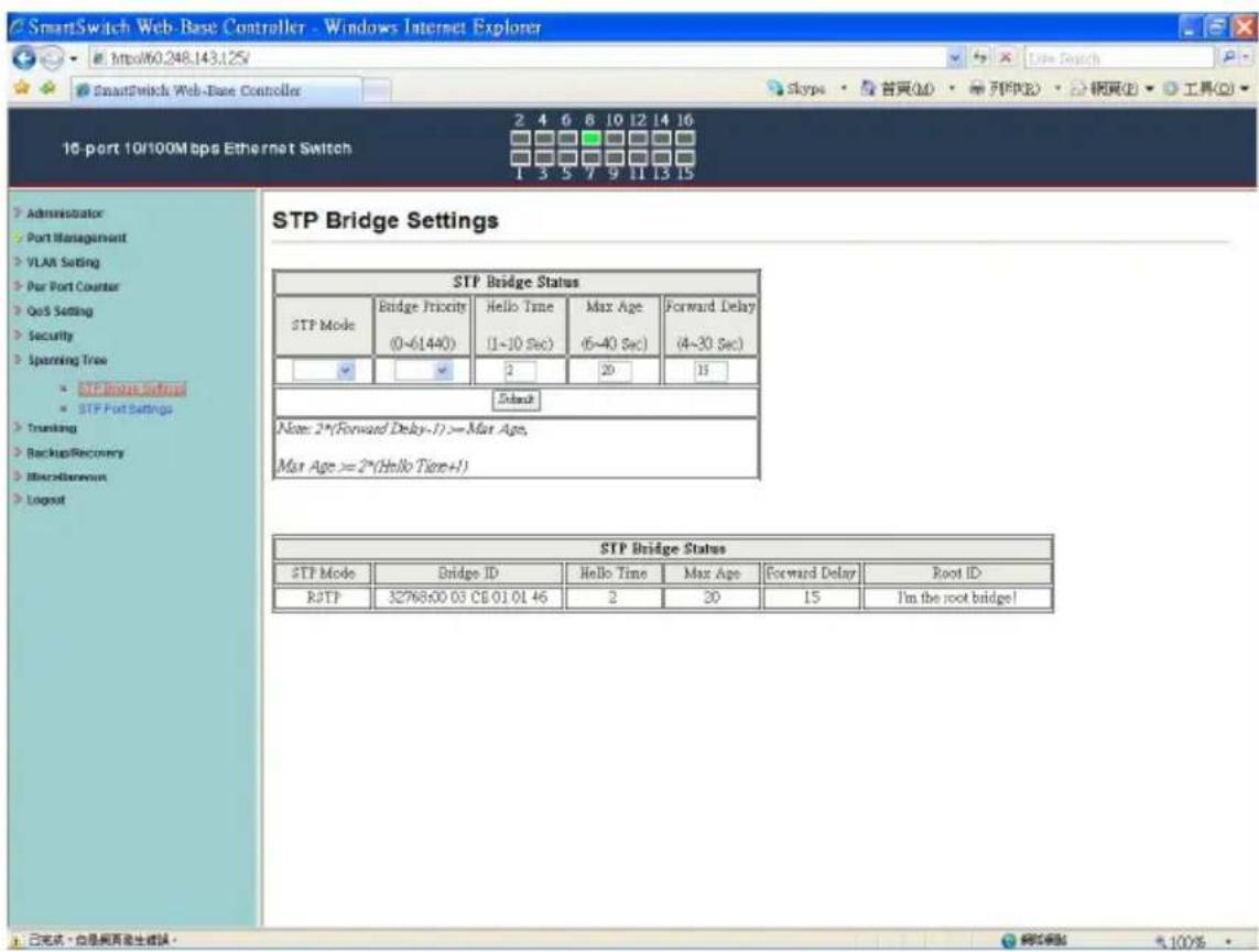
SmartSwitch Web-Base Controller - Windows Internet Explorer Http60.248.143.125 16 port 10/100M bps Ethernet Switch StP Bridge Settings STP Bridge Status STP Mode Bridge Price (0~61440) Hello Time Max Age Forward Delay (1~10 Sec) (5~40 Sec) (4~30 Sec) 2 20 15 Enable Note: 2*(Forward Delay-1) >= Max Age, Max Age >= 2*(Hello Time+1) STP Bridge Status STP Mode Bridge ID Hello Time Max Age Forward Delay Root ID RJTP 32768600 03 CB 01 01 46 2 20 15 I'm the root bridge! 已完成 - 性是网页发生错误。

This setting is to avoid the loop network.

  1. Select the "STP Mode"- choose "Disable", "STP" or "RSTP"
  2. Set the "Bridge Priority" – Set the priority of the Bridge
  3. Set the period of "Hello Time" packet – Provides the time period between root bridge configuration messages.
  4. Set the "Max Age" – Indicates when the current configuration message should be deleted.
  5. Set the “Forward Delay” time – Provides the length of time that bridges should wait before transitioning to a new state after a topology change. (If a bridge transitions too soon, not all network links might be ready to change their state, and loops can result.)
  6. Click "Update" to confirm and finish the setting.
    Now, the setting of "STP Bridge Settings" is finished.

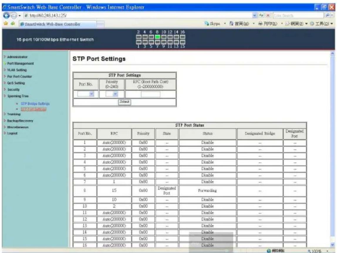
Spanning Tree: STP Port Settings
SmartSwitch Web-Base Controller - Windows Internet Explorer http://60.248.143.125/ SmartSwitch Web-Base Controller 16 port 10/100M bps Ethernet Switch 2 4 6 8 10 12 14 16 Skype · 首頁(M) · 列印(R) · 網頁(P) · 工具(Q) 2 3 5 7 9 11 13 15 STP Port Settings STP Port Settings Port No. Priority (0-240) RFC (Root Path Cost) (1-200000000) Status STP Port Status Port No. RFC Priority State Status Designated Bridge Designated Port No. Priority State Status Designated Bridge Designated Port No. Priority State Status Designated Bridge Designated Port No. Priority State Status Designated Bridge Designated Port No. Priority State Status Designated Bridge Designated Port No. Priority State Status Designated Bridge Designated Port No. Priority State Status Designated Bridge Designated 1 Auto(200000) 0x80 -- Disable -- -- 2 Auto(200000) 0x80 -- Disable -- -- 3 Auto(200000) 0x80 -- Disable -- -- 4 Auto(200000) 0x80 -- Disable -- -- 5 Auto(200000) 0x80 -- Disable -- -- 6 Auto(200000) 0x80 -- Disable -- -- 7 1 0x80 -- Disable -- -- 8 15 0x80 Designated Port Designated Port No. Priority State Status Designated Bridge Designated Port No. Priority State Status Designated Bridge Designated Port No. Priority State Status Designated Bridge Designated Port No. Priority State Status Designated Bridge Designated Port No. Priority State Status Designated Bridge Designated Port No. Priority State Status Designated Port No. Priority State Status Designated Bridge Designated Port No. Priority State Status Designated Bridge Designated Port No. Priority State Status Designated Bridge Designated Port No. Priority State Status Designated Bridge Designated Port No. Priority State Status Designated Bridge Designated Port No. Priority State Status Standard Port No. Priority State Status Port No. Priority_ State Port No. Priority_ State Port No. Priority_ State Port No. Priority_ State Port No. Priority_ State Port No. Priority_ State Port No. Priority_ State Port No. Priority_ State Port No. Priority_ State Port No. Priority_ State Port No. Priority_ State Port No. Priority_ State

  1. Choose "Port No." : Port 1 \~ Port 16
  2. Choose "Priority": 0\~240
  3. “RPC” = Root Path Cost: 0 = AUTO. When the loop is found, the STP/RSTP will calculate the cost of its path.

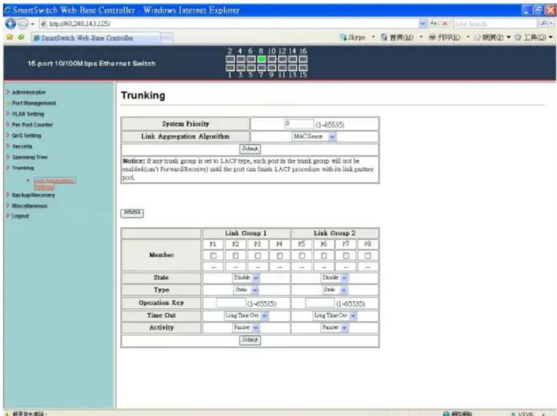
SmartSwitch Web-Base Controller - Windows Internet Explorer http://60.248.143.125/ SmartSwitch Web-Base Controller 16-port 10/100M bps Ethernet Switch 2 4 6 8 10 12 14 16 1 3 5 7 9 11 13 15 Administrator Port Management VLAN Setting Per Port Counter GoS Setting Security Spinning Tree Trunking Link Aggregation Settings BackupRecovery Miscellaneous Logout Trunking System Priority 0 (1-65535) Link Aggregation Algorithm MACScore Submit Notice: If any trunk group is set to LACF type, each port in the trunk group will not be enabled(can't Forward/Receive) until the port can finish LACF procedure with its link partner port. RESET Link Group 1 Link Group 2 Member P1 P2 P3 P4 P5 P6 P7 P8 □ □ □ □ □ □ □ □ -- -- -- -- -- -- -- State Disable Disable Type State Operation Key (1-65535) (1-65535) Time Out Long Time Out Long Time Out Activity Passive Passive Stop

There are two groups to choose and max. for each group is 4 ports.

Click "Submit" to confirm and finish the setting.

“State” – Enable / Disable

“Type” – LACP/ Static

“Activity” – Active/Passive: Both switches use “LACP” to configure the Trunk, at least one of them should be “Active”.

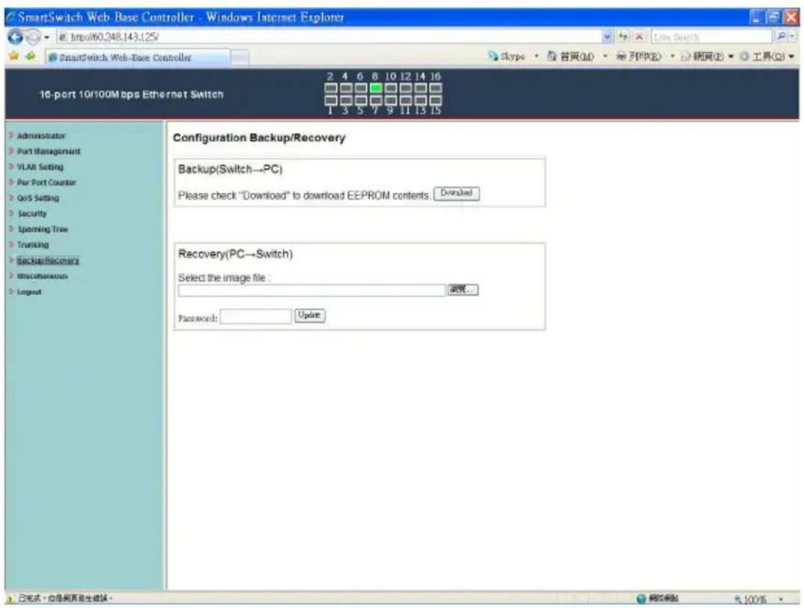
Backup/Recovery
SmartSwitch Web-Base Controller - Windows Internet Explorer http://60.248.143.125/ SmartSwitch Web-Base Controller Skype · 首頁(M) · 列印(P) · 網頁(B) · 工具(O) 10-port 10/100M bps Ethernet Switch Configuration Backup/Recovery Backup(Switch→PC) Please check "Download" to download EEPROM contents. Downloaded Recovery(PC→Switch) Select the image file: 摘要... Password: Update 已完成,但是网页发生错误。 确定模板 510%

Follow the instruction on the screen to update the original setting.

"Backup" - Click "Download" to confirm the setting.

“Recovery” – select a file and key in the password → Click “Update” to confirm the setting.

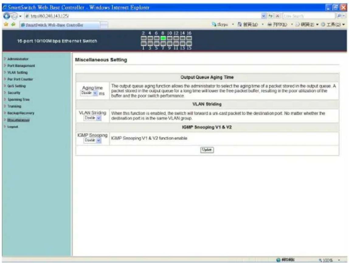
Miscellaneous: Miscellaneous Setting
SmartSwitch Web-Base Controller - Windows Internet Explorer http://60.248.143.125/ SmartSwitch Web-Base Controller Skype · 首頁(M) · 列印(R) · 統頁(P) · 工具(Q) 16-port 10/100M bps Ethernet Switch 2 4 6 8 10 12 14 16 1 3 5 7 9 11 13 15 Miscellaneous Setting Output Queue Aging Time Aging time Double ms The output queue aging function allows the administrator to select the aging time of a packet stored in the output queue. A packet stored in the output queue for a long time will lower the free packet buffer, resulting in the poor utilization of the buffer and the poor switch performance. VLAN Striding VLAN Striding Double When this function is enabled, the switch will forward a uni-cast packet to the destination port. No matter whether the destination port is in the same VLAN group. IGMP Snooping V1 & V2 IGMP Snooping Double IGMP Snooping V1 & V2 function enable Update Administrator Port Management VLAN Setting Par Port Counter QoS Setting Security Spanning Tree Tranking BackupRecovery Background Logout

  1. “Output Queue Aging Time” - You can set queue aging time into different milliseconds or disable this function.
  2. “VLAN Striding” – You can enable/disable this function.
  3. “IGMP Snooping V1 & V2” – You can enable/disable this function.
  4. “VLAN Uplink Setting” – Set “uplink1 or uplink2” or “Clear uplink1” or “Clear uplink2”
  5. Click "Update" to confirm and finish the setting.
    6.

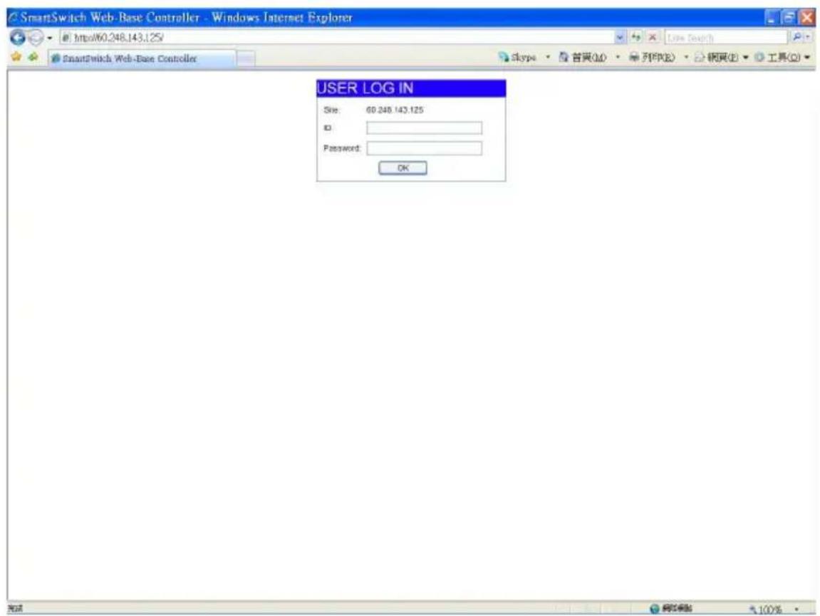
Logout: You can click "Logout" to logout.
SmartSwitch Web-Base Controller - Windows Internet Explorer http://60.248.143.125/ SmartSwitch Web-Base Controller Skype · 首頁(M) · 列印(R) · 網頁(P) · 工具(O) USER LOG IN Site: 60.248.143.125 ID: Password: OK

Manual assistant
Powered by Anthropic
Waiting for your message
Product information

Brand : Edimax

Model : ES-5816P

Category : Network switch