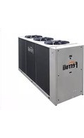
RGA - Heat pump FERROLI - Free user manual and instructions
Find the device manual for free RGA FERROLI in PDF.


| Product Type | Air-water heat pump (chiller or reversible heat pump) |
| Model Range | RGA IR (cooling only) and IP (reversible) from 40.2 to 200.2 |
| Power Supply | 400 V / 3 ph / 50 Hz (3+N for smaller models, 3 for larger) |
| Refrigerant | R410A |
| Compressor Type | Scroll compressors (2 per unit) |
| Expansion Valve | Thermostatic (standard IR) or electronic (standard IP, optional IR) |
| Heat Exchanger (Plant Side) | Brazed plate, stainless steel AISI 316 |
| Heat Exchanger (Source Side) | Finned coil with copper pipes and aluminium louvered fins |
| Fans | Axial fans with external rotor; variable speed control optional |
| Acoustic Settings | AB (base), AS (low noise), AX (extra low noise) |
| Transport Weight | From 300 kg (model 40.2) to 950 kg (model 200.2) |
| Operating Range (Cooling) | Outdoor air: -10°C to 46°C; water outlet: 5°C to 20°C |
| Operating Range (Heating, IP only) | Outdoor air: -15°C to 40°C; water outlet: 25°C to 60°C |
| Controller | Microprocessor with display, user interface, Modbus communication |
| Protection Devices | High/low pressure switches, safety valve, differential pressure switch, antifreeze heater |
| Hydronic Kit Options | Standard or high head pumps (single, double, modulating); buffer tank available |
| Accessories | Rubber/spring vibration dampers, water flow switch, remote control, outdoor air sensor |
| Maintenance Intervals | Weekly: visual; Monthly: hydraulic/electrical; Every 6 months: condensing coils, operating parameters |
| Safety Compliance | CE marked; complies with 2006/42/EC, 2004/108/EC, 2006/95/EC, 97/23/EC (PED) |
| Installation | Outdoor installation; only electrical and hydraulic connections required |
Frequently Asked Questions - RGA FERROLI
User questions about RGA FERROLI
0 question about this device. Answer the ones you know or ask your own.
Ask a new question about this device
Download the instructions for your Heat pump in PDF format for free! Find your manual RGA - FERROLI and take your electronic device back in hand. On this page are published all the documents necessary for the use of your device. RGA by FERROLI.
USER MANUAL RGA FERROLI
natural_image
Technical line drawing of a multi-compartment industrial cooling unit with four fans (no text or symbols)

CE
INSTALLATION AND OPERATION MANUAL
Dear Customer,
Thank you for having purchased a FERROLI product. It is the result of many years of experiences and of particular research studies and has been made with top quality materials and advanced technologies. The CE mark guarantees that the products satisfy all the applicable European Directives.
The qualitative level is kept under constant control and FERROLI products therefore offer SAFETY, QUALITY and RELIABILITY. Due to the continuous improvements in technologies and materials, the product specification as well as performances are subject to variations without prior notice.
Thank you once again for your preference
FERROLI S.p.A
THIS MANUAL IS DIVIDED INTO SECTIONS. THEIR NAMES APPEAR IN THE HEADING OF EACH PAGE.
GENERAL FEATURES 4
General specifications 4
European Directives....4
Identification plate of the Unit. 4
Presentation of the unit 5
Unit identification code....6
Description of the component 7
ACCESSORIES AND OPTIONAL EQUIPMENT....12
"Storing and hydronic kit" options 12
Options....13
Accessori 14
Mechanical options 14
Electrical options 14
TECHNICAL DATA - BASE VERSION (VB) 15
Technical data 15
NOMINAL performances - Base setting up (AB) - Standard plants 16
NOMINAL performances - Base setting up (AB) - Radiant plants 17
NOMINAL performances - Low noise setting up (AS) - Standard plants 18
NOMINAL performances - Low noise setting up (AS) - Radiant plants 19
NOMINAL performances - Exta low noise setting up (AX) - Standard plants 20
NOMINAL performances - Extra low noise setting up (AX) - Radiant plants 21
Standard performances in cooling mode IR - Base setting up AB 22
Standard performances in cooling mode IR - Low noise setting up (AS). 24
Standard performances in cooling mode IR - Extra low noise setting up (AX) 26
Standard performances in cooling mode IP - Base setting up (AB)....28
Standard performances in cooling mode IP - Low noise setting up (AS) 30
Standard performances in cooling mode IP - Extra low noise setting up (AX). 32
Standard performances in heating mode IP - Base setting up (AB) 34
Standard performances in heating mode IP - Low noise setting up (AS) 35
Standard performances in heating mode IP - Extra low noise setting up (AX) 36
Correction factor for the use of glycol in heating mode 37
Correction factor for the use of glycol in cooling mode 38
Fouling factors 38
TECHNICAL DATA - BR - BP UNIT 39
Mandatory requirements for BR and BP units 39
TECHNICAL DATA - IR DESUPERHEATER VERSION (VD) 40
Base setting up AB. 40
Low noise setting up AS....40
Extra low noise setting up AX. 40
Performances....41
TECHNICAL DATA - IP DESUPERHEATER VERSION (VD) 42
Base setting up AB. 42
Low noise setting up AS. 42
Extra low noise setting up AX. 42
Performances....43
TECHNICAL DATA - IR RECOVERY VERSION (VR)....44
Base setting up AB. 44
Low noise setting up AS....44
Extra low noise setting up AX. 44
Performances....45
NOISE LEVELS 46
Base setting up AB. 46
Low noise setting up AS....46
Extra low noise setting up AX. 46
OPERATING RANGE 47
Operating range 47
WATER PRESSURE DROP 48
Plant side exchanger 48
Desuperheaters 49
Total recovery exchanger....50
WORKING HEAD. 51
Standard working head pumps 51
High working head pumps 52
DIMENSIONAL AND PHYSICAL DATA....53
Overall dimensions....53
Description of the components....54
Minimum space required for operation....55
Position of condensate drain 55
Vibration-damper installation 55
Area of support. 56
Transport weight 57
Operation weight 58
Inspections on arrival....60
Safety prescriptions 60
Handling....60
Storage....61
Packing removing....61
Positioning 62
HYDRAULIC CONNECTIONS....63
General rules 63
Protection devices 63
Tips for a successful installation 63
Water component for corrosion limit 64
Precautions for the Winter 64
Basic diagram Standard Unit VB [PLANT SIDE WATER CIRCUIT] 65
Basic diagram for units with Recovery [RECOVERY WATER CIRCUIT]....65
Air vent and water drain 66
Piping connection with Victaulic couplings and Water flow switch 66
Valve regulating diagram valve 66
MAXIMUM VOLUME OF WATER 68
Maximum volume of water in the system with wet module 68
ELECTRICAL CONNECTIONS....69
General rules 69
Structure of the electric panel 69
Composition of the system....69
Electrical connections 69
R410A PROTECTION DEVICES....73
Refrigerant flow diagram IR VB unit with thermostatic expansion valve 74
Refrigerant flow diagram IR VB unit with thermostatic expansion valve 75
Refrigerant flow diagram IP VB unit with electronic expansion valve 76
Refrigerant flow diagram IR VR unit with thermostatic expansion valve 77
USER INTERFACE 78
Keys 78
Display 79
Menu structure - Main controller 80
INPUTS AND OUTPUTS 82
Inputs and outputs 82
CONTROLLER TECHNICAL DATA 84
ALARMS 85
AVAILABLE FUNCTIONS....89
ST-BY of the unit 89
Operation mode selection 89
Remote ST-BY 89
Working mode remote change-over cooling / heating 89
Set point....89
Antifreeze 89
Supplementary electrical heating elements 89
Dinamic setpoint. 90
Plant pump on-off control 90
Plant pump modulating control 90
Demand limit 90
Funzione economy 91
Recording hours of operation....91
Power failure 91
Clock 91
History alarms 91
Total recovery function (VR unit only) 91
Automatic change-over 92
Date and time set up 92
Timer scheduling 93
PARAMETERS 95
Common parameters 95
Specific parameters for VR unit 95
CONFIGURABLE INPUTS 96
PROBE CHARACTERISTICS 97
NETWORK COMUNICATION 98
Modbus address table 99
START-UP 100
General Rules 100
MAINTENANCE....100
General Rules 100
Routine maintenance....100
General considerations 102
SAFETY AND POLLUTION....103
Refrigerant safety card....103
First aid 104
DECLARATION OF CONFORMITY 107
GENERAL FEATURES
General specifications
- This manual and the wiring diagram supplied with the unit must be kept in a dry place and ready to hand for future consultation when required.
- This manual has been compiled to ensure that the unit is installed in the correct way and to supply comprehensive information about how to correctly use and service the appliance. Before proceeding with the installation phase, please carefully read all the information in this manual, which describes the procedures required to correctly install and use the unit.
- Strictly comply with the instructions in this manual and conform to the current safety standards.
- The appliance must be installed in accordance with the laws in force in the country in which the unit is installed.
- Unauthorized tampering with the electrical and mechanical equipment will VOID THE WARRANTY.
- Check the electrical specifications on the identification plate before making the electrical connections. Read the instructions in the specific section where the electrical connections are described.
- If the unit must be repaired for any reason, this must only be done by a specialized assistance center recognized by the manufacturer and using genuine spare parts.
- The manufacturer also declines all liability for any damage to persons or property deriving from failure of the information in this manual to correspond to the actual unit in your possession.
- Proper uses: this series of chillers is designed to produce cold or hot water for use in hydronic systems for conditioning/heating purposes. The units are not suitable for the production of domestic hot water.
Any use differing from this proper use or beyond the operating limits indicated in this manual is forbidden unless previously agreed with the manufacturer.
- The prevention of the risk of fire at the installation site is the responsibility of the end user.
European Directives
The company hereby declares that the unit in question complies with the matters prescribed by the following Directives:
• Unit Directive 2006/42/CE
- Directive governing pressurized vessels (PED) 97/23/CE
• Electromagnetic compatibility Directive (EMC) 2004/108/CE
• Low voltage Directive (LVD) 2006/95/CE
Any other Directives have to be considered not applicable.
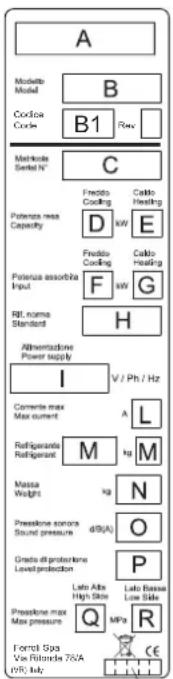
Identification plate of the Unit
S
The figure on the left depicts the identification plate of the unit, affixed to the outer left-hand side of the Electric Panel.
A description of the data is given below:
Standard versions
A - Trademark
B - Model
B1- Code
C - Serial number
D - Cooling Capacity
E - Heating Capacity
F - Power input in COOLING mode
G - Power input in HEATING mode
H - Reference standard
I - Electric power supply
L - Maximum load current
M - Type of refrigerant and charge
N - Shipping weight of the unit
O - Sound pressure level at 1m
P - IP Level Protection
Q - Maximum pressure - High Side
R - Maximum pressure - Low Side
S - PED certification authority
Special versions
A - Trademark
B - Model
B1- Code
C - Serial number
D - Cooling Capacity (same as Standard Version of the unit)
E - Heating Capacity
for IR unit, VD version, Recovered Heating Capacity
for IP unit, VD version, Heating Capacity / Recovered Heating Capacity
F - Power input in COOLING mode (same as Standard version of the unit)
G - Power input in HEATING mode
H - Reference standard
I - Electric power supply
L - Maximum load current
M - Type of refrigerant and charge
N - Shipping weight of the unit
O - Sound pressure level at 1m
P - IP Level Protection
Q - Maximum pressure - High Side
R - Maximum pressure - Low Side
S - PED certification authority
NOTE: The identification plate of the Brine Unit (BR - BP) is filled out as shown in the diagram for the Basic Version of the unit (VB).
GENERAL FEATURES
Presentation of the unit
This series of air-water chillers and heat pumps satisfies the cooling and heating requirements of residential plants of medium size. All the units are suitable for outdoor installation and can be applied to fan coil plants, radiant floor plants and high efficiency radiators plants.
The refrigerant circuit, contained in a compartment protected from the air flow to simplify the maintenance operations, is equipped with scroll compressors mounted on damper supports, brazed plate heat exchanger, thermostatic expansion valve (standard for IR) or electronic expansion valve (standard for IP / option for IR), reverse cycle valve, dehydrator filter, axial fans with safety protection grilles, finned coil made of copper pipes and aluminium louvered fins with subcooling section. The circuit is protected by a safety gas valve, high and low pressure switches and differential pressure switch on the plate heat exchanger. The plate heat exchanger and all the hydraulic pipes are thermally insulated in order to avoid condensate generation and to reduce thermal losses.
All the units can be equipped with variable speed fans control that allows the units to operate with low outdoor temperatures in cooling and high outdoor temperature in heating and permits to reduce noise emissions in such operating conditions.
The low noise acoustic setting up (AS) is obtained, starting from the base setting up (AB), reducing the rotational speed of the fans and mounting sound jackets on the compressors and the technical compartment is clad with soundproofing material of suitable thickness.
The eXtra low noise acoustic setting up (AX) is obtained, starting from the low noise setting up (AS), further reducing the rotational speed of the fans and using finned coil with bigger surface.
All the units are supplied with a management and control electrical panel containing general switch, phase presence and correct sequence controller, microprocessor controller with display and all the other electrical components with IP54 minimum protection degree.
All the units are accurately built and individually tested in the factory. Only electric and hydraulic connections are required for installation.

natural_image
Technical line drawing of a multi-compartment industrial cooling unit with multiple fans (no text or symbols)GENERAL FEATURES
Unit identification code
The codes that identify the units and the meaning of the letters used are described below.
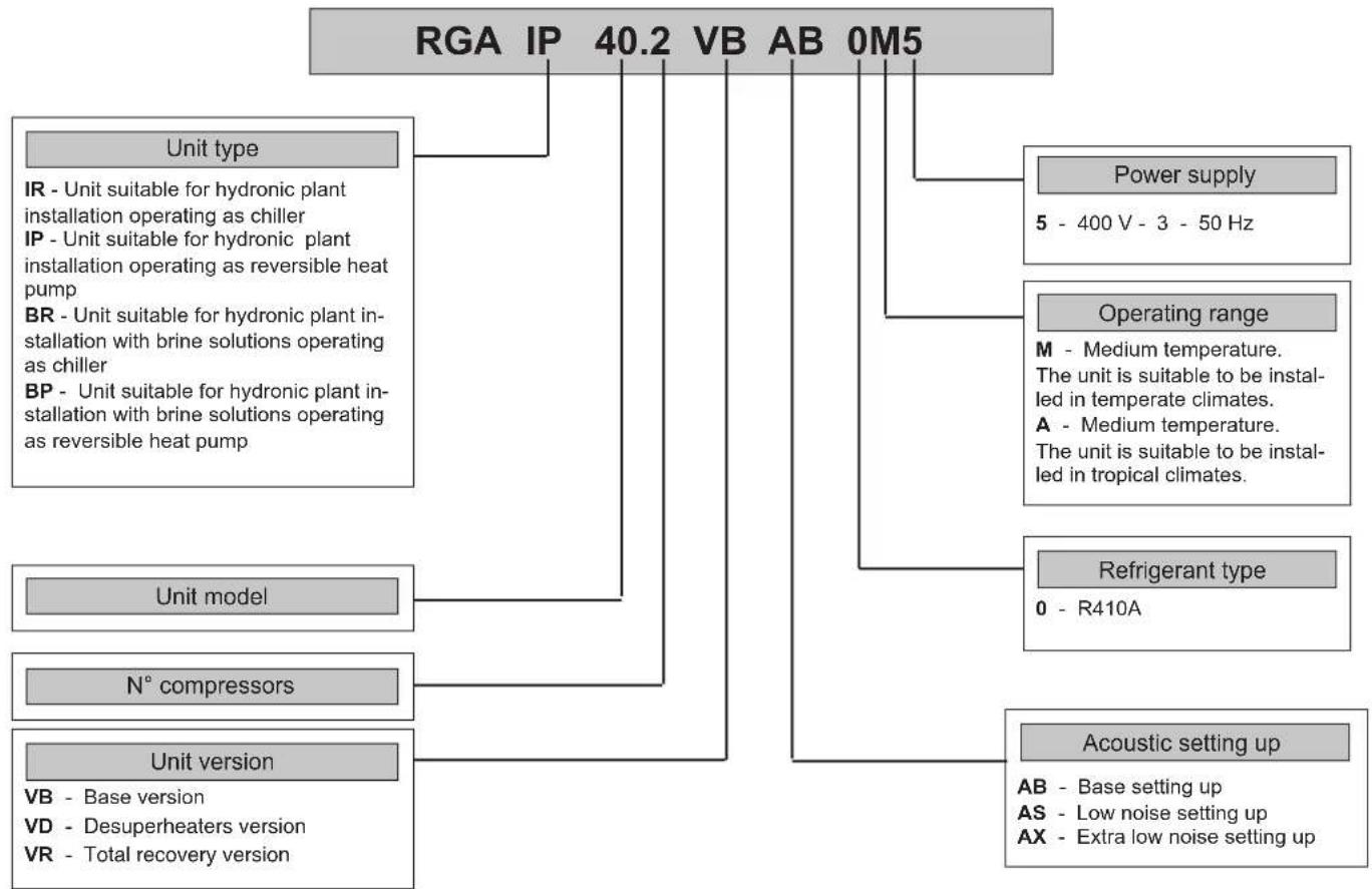
flowchart
graph TD
    A["RGA IP 40.2 VB AB 0M5"] --> B["Unit type"]
    A --> C["Power supply"]
    A --> D["Operating range"]
    A --> E["Refrigerant type"]
    A --> F["Acoustic setting up"]
    B --> G["IR - Unit suitable for hydronic plant installation operating as chiller"]
    B --> H["IP - Unit suitable for hydronic plant installation operating as reversible heat pump"]
    B --> I["BR - Unit suitable for hydronic plant installation with brine solutions operating as chiller"]
    B --> J["BP - Unit suitable for hydronic plant installation with brine solutions operating as reversible heat pump"]
    C --> K["5 - 400 V - 3 - 50 Hz"]
    D --> L["M - Medium temperature. The unit is suitable to be installed in temperate climates."]
    D --> M["A - Medium temperature. The unit is suitable to be installed in tropical climates."]
    E --> N["0 - R410A"]
    F --> O["AB - Base setting up"]
    F --> P["AS - Low noise setting up"]
    F --> Q["AX - Extra low noise setting up"]
    G --> R["Unit model"]
    H --> S["N° compressors"]
    I --> T["Unit version"]
    J --> U["Unit version"]
    K --> V["Unit version"]
    L --> W["N° compressors"]
    M --> X["Unit version"]
    N --> Y["Unit version"]
    O --> Z["Unit version"]
    P --> AA["Unit version"]
    Q --> AB["Unit version"]
The available special versions are described below:
VB: Standard unit.
VD: Version with Desuperheater (available for both IR units and IP units)
Produces cold water in the same way as the standard version plus hot water from 30 to 70°C at the same time. This is achieved by installing a water-refrigerant gas heat exchanger between the compressor and coils in order to recover 25 to 30% of the heating capacity that would otherwise be dispersed in the air. It helps to remind that hot water production is possible only in combination with cold-hot water production in the main heat exchanger and it is subordinated by it.
VR: Total Heat Recovery version
Produces cold water as in the standard version plus hot water at a temperature of 30 to 55°C at the same time. This is achieved thanks to a water-refrigerant gas heat exchanger that totally recovers the heating capacity that would otherwise be dispersed in the air. The total heat recovery function is enabled and disabled by means of a valve on the compressor delivery of each circuit: when the temperature of the water that enters the recuperator drops, the valve switches the hot gas flow from the condensing coils to the recovery heat exchanger. On the other hand, when the temperature of the water reaches the set-point, the valve shuts off the heat recuperator and switches the hot gas flow to the condensing coils. It helps to remind that hot water production is possible only in combination with cold water production in the main heat exchanger and it is subordinated by it.
GENERAL FEATURES
Description of the component
-
Fans. Axial type, they are contained in a sheet nozzle and are equipped with a safety grille, scythe-shaped blades increase the efficiency and reduce the noise level. The fans are directly coupled to the single-phase motor by means of an external rotor. Thermal protection against operating faults is installed inside the winding. The fans rotational speed can be modulated continuously by an analogue device or an inverter (option) to control the condensation pressure (in cooling) and the evaporation pressure (in heating) in order to extend the operating limits of the unit and to reduce noise emissions. Optionally are available Electronically Commutated (EC) fans, which ensure maximum energy efficiency at reduced speed of rotation.
-
Electric control and monitoring panel. It contains all the power, control and security components necessary to guarantee the unit to work properly. The unit is managed by a microprocessor controller to which all the electrical loads and the control devices are connected. The user interface, placed on the frontal panel, allows to view and to modify, if necessary, all the parameters of the unit. This is housed in a metal casing in which the various electrical components are positioned on one metal plate.
2a. The power section includes:
- Main door-locking circuit-breaker.
- Fuse-holder that can be isolated with protection fuse triad for each compressor, or thermal magnetic circuit breakers (option).
- Fuse-holder that can be isolated with protection fuse for compressor oil heaters and antifreeze (if installed), or thermal magnetic circuit breakers (option).
- Control contactor for each compressor or soft starters (option).
- Protection fuse for the fans, or thermal magnetic circuit breakers (option).
- Thermal magnetic contactor switch to protect the pump (if the Hydronic Kit is installed).
- Phase presence and sequence monitoring device on power supply, or voltage monitor and sequence meter (accessory).
2b. The auxiliary section includes:
- Fuses on the auxiliary transformer, or thermal magnetic circuit breakers (option).
- Electromagnetic noise filter
- Adjusting fan speed board (option)
- Insulating and safety transformer to power the auxiliary circuit.
2c. The microprocessor monitoring section includes:
- User interfacing terminal with display.
- On-off key.
- Operating mode selector key.
- Compressor on-off display LED.
• Operational mode LED
- Antifreeze heaters activated indicator LED.
- Fans on-off display LED
- Pumps on-off display LED
- Check-control with fault code display
- Defrosting, alarm, economy, stand-by LED.

Control system main functions:
temperature control of the water produced by the unit, compressor and pump operating hour counter, timing and cycling of start-ups, input parameters by keyboard, alarms management, smart defrosting control and operating mode change (only IP unit), dynamic set-point (climatic control), scheduling and integrative heaters control.
If you installed the hydronic kit these functions are enabled: antifreeze with pump, start-up cycle after prolonged inactivity (anti-sticking), if the hydronic kit installed has 2 pumps there is a cycling between each pump to ensure an equivalent lifetime, with inverter modulating hydronic kit the water flow of the plant can be adjusted.
Digital input functions: low pressure, high pressure, high temperature on compressor supply, phase presence and sequence monitoring device on power supply, differential water pressure control, compressors thermal protection, fans thermal protection, pumps thermal protection (only if installed MP accessory), ON/OFF and remote operating mode change, demand limit and Economy function, recovery enabling (only for the VR Version), recovery Pump Thermal Protective (only for the VR Version), recovery differential water pressure control (only for the VR Version).
Digital output functions: compressor start-up, pump start-up (only with MP accessory), plate heat exchanger electrical heater, remote general alarm, 4-way valve (only IP unit), integrative heaters and clean contact on compressors start-up, recovery valve management (only for the VR Version), recovery pump management (only for the VR Version).
Analogic input functions: in and out water temperature, coil temperature probe, external air temperature probe (if present), in and out recovery water temperature (only for the VR Version).
Analogic output functions: continuous adjustment of axial fans rotating speed (option for AB and standard for AS and AX acoustic setting up), continuous adjustment of pump rotating speed (only if hydronic kit with modulating pump is installed).
GENERAL FEATURES
-
Compressors. They are the SCROLL type with orbiting coil equipped with built-in thermal protection and oil heater (accessory for IR, as standard for IP). The AS unit includes: a soundproofing jacket for the compressors, to reduce noise level. All units are equipped with two compressors connected in parallel (1 single cooling circuit) which can operate at the same time (100% cooling power) or individually (50% of the cooling power), thus adapting to the different thermal loads of the system supplied.
-
Frame, supporting structure and lateral panels are made of galvanized and painted sheet-steel (colour RAL 7035) to guarantee good resistance to the weather. Accessibility to internal parts is possible removing the frontal panel, for other manteinances also the lateral panel can be removed.
-
Evaporator made of brazed stainless steel plates (AISI 316). It is installed in a shell of heat-insulating material to prevent the formation of condensation and heat exchanges towards the outside. Standard supply also includes antifreeze heater a differential pressure switch on the water circuit to avoid the risk of freezing if the water flow is shut off for some reason.
-
Condensing coils, the aluminium finned pack type with shaped profile to increase the heat exchange coefficient and with copper pipes arranged in staggered rows. A sub-cooling section is integrated into the lower part.

GENERAL FEATURES
Hydraulic and cooling circuit components
-
One-way valves (IP unit only), allowing the refrigerant gas to pass into the appropriate exchangers, depending on the operating cycle.
-
4-way cycle reversal valve (IP unit only), reverses the flow direction of the refrigerant gas as the summer/winter operating mode is changed.
-
Safety valve. Installed on the delivery pipe of the compressors, this operates if extreme faults should occur in the plant.
-
Fluid valve (accessory). Ball type, this allows the gas flow on the fluid line to be turned on and off. Along with the cock on the compressor delivery, it allows the components of the fluid line to be subjected to extraordinary maintenance work and the compressors to be replaced if necessary (without discharging the refrigerant gas from the unit).
-
Compressor delivery valve (accessory). Ball type, allows the gas delivered to the compressors to be turned on and off.
-
Dehydrator filter. Mechanical type. Retains impurities and traces of moisture in the circuit.
Hermetic type for mod. 40÷100 or a cartridge type for mod. 115÷200.
-
Fluid and humidity indicator. Signals when fluid passes through the circuit, indicating that the refrigerant gas charge is correct. The fluid indicator light also indicates the amount of moisture in the refrigerant gas by changing colour.
-
Low pressure switch (N°1 of series IR version, N°2 of series IP version). With fixed setting. It is installed on the suction pipe and blocks the compressors if the operating pressures drop below the tolerated values. Automatically resets as the pressure increases. If it activates frequently, the unit will block and can only be restarted by resetting via the user interface terminal.
-
High pressure switch (n°2). With fixed setting. Are is installed on the delivery pipe and blocks the compressors if the operating pressures exceed the tolerated values. If it activates, the unit will block and can only be restarted by resetting via the user interface terminal.
16. Expansion valve:
- Thermostatic valve (standard for IR and BR unit) with external equalizer, this supplies the evaporator correctly, keeping the selected overheating degree at a steady level.
- Electronic valve (standard for IP and BP unit, optional for IR and BR unit) supplies the evaporator correctly, keeping the selected overheating degree at a more steady level; ensures a faster response to load changes and superior stability which translates into increased efficiency at partial loads.
-
Water differential pressure switch. This is standard supply and is installed on the connections between the water inlet and outlet of the exchanger. It stops the unit if it activates.
-
Pressure taps: 1/4 " SAE (7/16" UNF) type with flow regulator. Allow the operating pressure of the system to be measured: compressor delivery, lamination component inlet, compressor intake.
-
Pressure taps: 5/16 " SAE type with flow regulator. Allow the charge/discharge of the gas from the system, precisely from compressor outlet an expansion valve inlet.
-
Electrical heating elements to heat the compressor oil. "Belt" type (accessory for IR, as standard for IP). These activate when the compressor turns off and keep the temperature of the oil sufficiently high so as to prevent refrigerant gas from migrating during these pauses.
Fluid receiver (IP unit only), this is a plenum tank that accounts for variations to the refrigerant gas charge the unit must supply as the summer/winter operating mode varies.
Fluid separator (IP unit only), on the compressor intake to protect against possible fluid back-flows.

GENERAL FEATURES
Desuperheater unit VD (available for both IR units and IP units)
Hydraulic and chilling circuit components:
- Desuperheater. Specially designed for the specific version. Plate type, made of stainless steel (AISI 316).
It is installed within a shell of thermal barrier insulating material to prevent heat exchanges towards the outside. Standard supply also includes an electric antifreeze heater to prevent the parts from freezing during the winter, when the system remains at a standstill (if not drained). - Water safety valve. On the heat recovery inlet pipe. It acts whenever faulty service leads to an operating pressure in the plumbing system that exceeds the valve opening value (Fig. 1).
- Water drain taps for emptying the exchangers and pipes of the unit dedicated to heat recovery (Fig. 1).
- Air vent. Accessed by removing the front panels. It consists of a manually operated valve installed in the highest part of the water pipes. To use in conjunction with the water drain cocks situated in the rear part of the unit, for emptying the exchangers and pipes dedicated to heat recovery.

GENERAL FEATURES
Total Heat Recovery unit VR (only available for IR units)
Hydraulic and cooling circuit components:
- Heat recovery exchanger. Specially designed for the specific version. Plate type, made of stainless steel (AISI 316). It is installed within a shell of thermal barrier insulating material to prevent heat dispersion towards the outside. Standard supply also includes an electric antifreeze heater to prevent the parts from freezing during the winter, if is it not drained.
- Differential water pressure switch. Installed on exchanger. It disables the heat recovery version if activated owing to lack of water flowing through the recovery exchangers.
- Heat recovery management valve. This delivers refrigerant to the condensing coils or heat recovery exchanger, depending on demands for hot water, and into the appropriate exchangers depending on whether hot water is required or not.
- Fluid receiver. This is a plenum tank that accounts for the refrigerant charge variations required by the unit as the operating modes change (condensing in air or in water).
- One-way valves. Make the refrigerant obligatorily pass through the appropriate heat exchangers (coils / heat exchanger), depending on the operating mode.

ACCESSORIES AND OPTIONAL EQUIPMENT
"Storing and hydronic kit" options
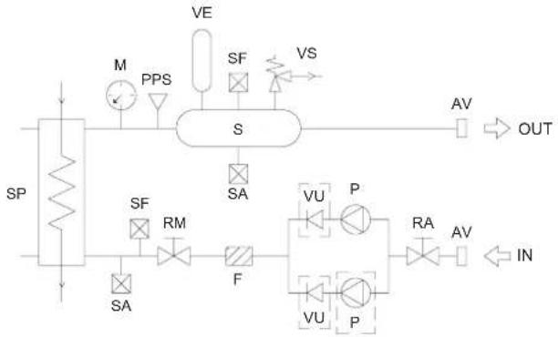
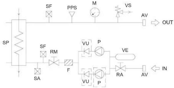
| Storing and hydronic kit | MKT SSPipe kit without tank | This accessory consists of steel pipes insulated with thermal barrier material and allows the water inlet/outlet connection to be routed outside the unit. |
| M1P SS 2P STD1 Standard pump | Allows the circulation of the water on the plant side. | |
| M1P SS 2P HP11 High head pump | Allows the circulation of the water on the plant side and guarantees a higher available static head, suitable for high pressure drop plants. | |
| M1PM SS 2P STD1 Standard modulating pump | Allows the circulation of the water on the plant side with the possibility to set the rotational speed of the pump in order to get the requested flow rate without the necessity to install other setting devices. | |
| M1PM SS 2P HP11 Standard modulating high head pump | Allows the circulation of the water on the plant side, ensuring a higher available static head, suitable for high pressure drop plants, with the possibility to set the rotational speed of the pump in order to get the requested flow rate without the necessity to install other setting devices. | |
| M2P SS 2P STD2 Standard pumps | Allows the circulation of the water on the plant side and includes a second pump installed as a backup to the first. | |
| M2P SS 2P HP12 High head pumps | Allows the circulation of the water on the plant side, ensuring a higher available static head, suitable for high pressure drop plants, and includes a second pump installed as a backup to the first. | |
| MKT AMPipe kit with tank | This accessory consists of steel pipes insulated with thermal barrier material and allows the water inlet/outlet connection to be routed outside the unit.The thermal inertia of the buffer tank allows to reduce the number of compressor starts and to guarantee a more stable flow temperature. | |
| M1P AM 2P STDTank and 1 standard pump | Allows the circulation of the water on the plant side.The thermal inertia of the buffer tank allows to reduce the number of compressor starts and to guarantee a more stable flow temperature. | |
| M1P AM 2P HP1Tank and 1 high head pump | Allows the circulation of the water on the plant side and guarantees a higher available static head, suitable for high pressure drop plants.The thermal inertia of the buffer tank allows to reduce the number of compressor starts and to guarantee a more stable flow temperature. | |
| M1PM AM 2P STDTank and 1 modulating standard pump | Allows the circulation of the water on the plant side with the possibility to set the rotational speed of the pump in order to get the requested flow rate without the necessity to install other setting devices.The thermal inertia of the buffer tank allows to reduce the number of compressor starts and to guarantee a more stable flow temperature. | |
| M1PM AM 2P HP1Tank and 1 modulating high head pump | Allows the circulation of the water on the plant side, ensuring a higher available static head, suitable for high pressure drop plants, with the possibility to set the rotational speed of the pump in order to get the requested flow rate without the necessity to install other setting devices.The thermal inertia of the buffer tank allows to reduce the number of compressor starts and to guarantee a more stable flow temperature. | |
| M2P AM 2P STDTank and 2 standard pumps | Allows the circulation of the water on the plant side and includes a second pump installed as a backup to the first.The thermal inertia of the buffer tank allows to reduce the number of compressor starts and to guarantee a more stable flow temperature. | |
| M2P AM 2P HP1Tank and 2 high head pumps | Allows the circulation of the water on the plant side, ensuring a higher available static head, suitable for high pressure drop plants, and includes a second pump installed as a backup to the first.The thermal inertia of the buffer tank allows to reduce the number of compressor starts and to guarantee a more stable flow temperature. | |
| M1P PS 2P STDTank and 1 standard pump(primary and secondary configuration) | Allows the circulation of the water on the primary between the tank and the heat exchanger.The thermal inertia of the buffer tank allows to reduce the number of compressor starts and to guarantee a more stable flow temperature. | |
| M2P PS 2P STDTank and 2 standard pumps(primary and secondary configuration) | Allows the circulation of the water on the primary between the tank and the heat exchanger and includes a second pump installed as a backup to the first.The thermal inertia of the buffer tank allows to reduce the number of compressor starts and to guarantee a more stable flow temperature. |
ACCESSORIES AND OPTIONAL EQUIPMENT
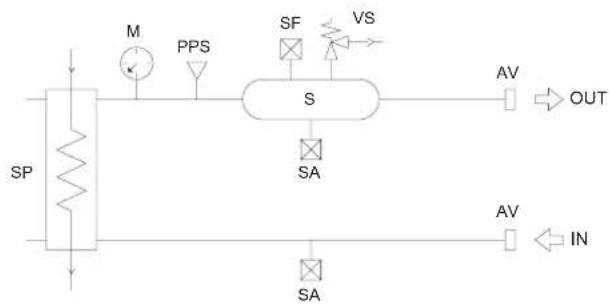
Pipe kit without tank Pipe kit with tank

flowchart
graph LR
    SP --> SFF
    SFF --> PPS
    PPS --> M
    M --> VS
    VS --> AV
    AV --> OUT
    SA --> AV
    IN --> AV
flowchart
graph TD
    A["SP"] --> B["M"]
    B --> C["PPS"]
    C --> D["S"]
    D --> E["SA"]
    E --> F["OUT"]
    D --> G["VS"]
    G --> H["AV"]
    H --> I["IN"]
    D --> J["SA"]
    J --> K["IN"]
Tank and standard pump
flowchart
graph TD
    A["SP"] --> B["SF"]
    B --> C["RM"]
    C --> D["F"]
    D --> E["VU"]
    E --> F["P"]
    F --> G["RA"]
    G --> H["IN"]
    I["M"] --> J["PPS"]
    K["VE"] --> L["S"]
    M["SF"] --> N["SA"]
    O["VS"] --> P["OUT"]
    Q["SA"] --> R["IN"]
Tank and standard pump (primary and secondary configuration)

flowchart
graph TD
    SP --> M
    M --> PPS
    PPS --> S
    S --> VS
    VS --> AV
    AV --> OUT
    SA --> RM
    RM --> F
    F --> VU
    VU --> P
    P --> RA
    RA --> SA
    SA --> VU
    VU --> P
    P --> VU
    VU --> IN
Standard pump
flowchart
graph TD
    A["SP"] --> B["SF"]
    B --> C["PPS"]
    C --> D["M"]
    D --> E["VS"]
    E --> F["AV"]
    F --> G["OUT"]
    H["SA"] --> I["RM"]
    I --> J["F"]
    K["VU"] --> L["P"]
    L --> M["VE"]
    N["VU"] --> O["P"]
    O --> P["RA"]
    Q["IN"] --> R["AV"]
| ITEM | DESCRIPTION |
| AV | VICTAULIC CONNECTIONS |
| F | FILTER |
| M | GAUGE |
| P | PUMP |
| PPS | PRESSURE SOCKET 1/4" SAE WITH CORE |
| RA | SUCTION BALL VALVE |
| RM | DISCHARGE BALL VALVE |
| S | TANK |
| SA | DRAIN WATER VALVE |
| SF | AIR VENT VALVE |
| SP | HEAT EXCHANGER |
| VE | EXPANSION VESSEL |
| VS | SAFETY VALVE |
| VU | CHECK VALVE |
--- only in case of 2 pumps
Options
| Expansion valve | Thermostatic | (standard for IR and BR unit) with external equalizer, this supplies the evaporator correctly, keeping the selected overheating degree at a steady level. |
| Electronic | (standard for IP and BP unit, optional for IR and BR unit) supplies the evaporator correctly, keeping the selected overheating degree at a more steady level; ensures a faster response to load changes and superior stability which translates into increased efficiency at partial loads. | |
| Soft starter Reduces the compressor start current of about 40%. | ||
| Compressor power factor correction | Allows to reduce the phase shift between the absorbed current and the power supply voltage keeping it above the value of 0,91. | |
| Fans control | On-off | (standard for AB unit) the condensation pressure (in cooling) and the evaporation pressure (in heating) is regulated by on-off cycles. |
| Modulating control (condensation / evaporation control) | (standard for AS and AX unit, optional for AB unit) The fans rotational speed can be modulated continuously by an adjusting fan speed device to control the condensation pressure (in cooling) and the evaporation pressure (in heating) in order to extend the operating limits of the unit, to reduce noise emissions and improve energy efficiency. | |
| Modulating control (condensation / evaporation control) with EC fans | (optional for AB, AS and AX unit) The fans rotational speed can be modulated continuously by EC fans (Electronic Commutation) to control the condensation pressure (in cooling) and the evaporation pressure (in heating) in order to extend the operating limits of the unit, to reduce noise emissions and maximize energy efficiency. | |
| Electrical protection load | Fuses Allows to protect the electrical loads with fuses. | |
| Thermal magnetic | Allows to protect the electrical loads with thermal magnetic circuit breakers simplifying the maintenance and reload operations. | |
ACCESSORIES AND OPTIONAL EQUIPMENT
Accessories
Supplied accessories
| Rubber vibration dampers | Allow to reduce the transmission to the unit support plane of the mechanical vibrations generated by the compressor and by the fans in their normal operating mode, the degree of isolation is about 85% |
| Spring vibration dampers | Allow to reduce the transmission to the unit support plane of the mechanical vibrations generated by the compressor and by the fans in their normal operating mode, the degree of isolation is about 90% |
| Water paddle flow switch | Allows to detect the water flow lack through the plate heat exchanger and operates as an integration of the protection offered by the differential pressure switch (standard). |
| Tank antifreeze electrical heater | Activated together with the antifreeze electrical heater of the plate heat exchanger, it has the task to keep the still water in the buffer tank at a temperature high enough to avoid ice generation during winter. |
| Remote control | It is suitable for wall mounting and reports all the control and visualization functions available on the user interface placed on the unit. It therefore allows the complete remote control of the unit. |
| Programmer clock | It allows the unit to be turned on and off according to a set program, through the digital input available on the unit wiring board (remote stand by). |
| Modbus serial interface on RS485 | It allows to communicate with the unit controller and to view the operating conditions of the unit through Modbus communication protocol. The RS485 serial line ensures the signal quality up to distances of about 1200 meters (that can be extended by means of proper repeaters). |
| Phase sequence and voltage controller | It checks not only the presence and correct order of the power supply phases but also the voltage level on each phase and avoid the unit to operate with voltage levels outside the permitted limits. |
Factory mounted accessories
| Victaulic connections | This accessory consists of steel pipes that allows the water inlet/outlet to be connected straight inside the unit. |
| Coil protection grilles | Protects the external surface of the finned coil. |
| High and low pressure gauges | 2 pressure gauges allow visualization of high and low refrigerant gas pressure. |
| Coil shut off valves | It consists of two ball valves installed before and after the coil that allow for the pump-down maintenance. |
| Outdoor air sensor | External air probe mounted near coil allows smart defrosting, climatic variation of setpoint and enables heat pump stop reducing the external air temperature below a setpoint. |
| High temperature thermostat | Two thermostats in series on compressors outlet pipes preserve operation not allowing temperature to rise up than a specified non adjustable value. |
| Low temperature kit | (di serie per unità IP e BP, optional per unità IR e BR) sono costituite da resistenze carter di riscaldamento olio compressori. |
| Tank antifreeze electrical heater | Activated together with the antifreeze electrical heater of the plate heat exchanger, it has the task to keep the still water in the buffer tank at a temperature high enough to avoid ice generation during winter. |
| Modbus serial interface on RS485 | It allows to communicate with the unit controller and to view the operating conditions of the unit through Modbus communication protocol. The RS485 serial line ensures the signal quality up to distances of about 1200 meters (that can be extended by means of proper repeaters). |
| Phase sequence and voltage controller | It checks not only the presence and correct order of the power supply phases but also the voltage level on each phase and avoid the unit to operate with voltage levels outside the permitted limits. |
| ATC Advanced temperature control | It consists of a properly calibrated pressure switch that partializes the unit preventing the high pressure alarm. |
| Pressure transducer | It consists of a transducer, which allows operation of the control condensation, evaporation and defrost by reading the pressure. |
Mechanical options
Electrical options
For finned coils with special treatment (copper fins, tin-copper plated, For other voltages, please contact our technical department acrylic, epoxy or hydrophilic painting) please contact our technical department.
TECHNICAL DATA - BASE VERSION (VB)
Technical data
| Frame 1 2 3 4 | |||||||||||||||
| Model 40.2 50.2 60.2 | 70.2 | 80.2 | 90 | 2 100 | 2 115 | 2 130 | 2 145 | 2 160 | 2 180 | 2 200 | 2 200 | 2 200 | 2 200 | 2 200 | U.M. |
| Power supply | 400 - 3+N - 50 400 - 3 - 50 | V-ph-Hz | |||||||||||||
| Refrigerant | |||||||||||||||
| Type R410A - | |||||||||||||||
| Refrigerant circuit | |||||||||||||||
| Quantity 1 - | |||||||||||||||
| Compressor | |||||||||||||||
| Type | scroll | - | |||||||||||||
| Quantity 2 | n° | ||||||||||||||
| Power steps | 0 - 50 - 100 | % | |||||||||||||
| Oil charge CP1A | 3,3 | 3,3 | 3,3 | 3,3 | 3,3 | 3,3 | 3,3 | 5,3 | 5,3 | 5,3 | 5,3 | 5,3 | 5,3 | 5,3 | I |
| Oil charge CP1B | 3,3 | 3,3 | 3,3 | 3,3 | 3,3 | 4,7 | 5,3 | 5,3 | 5,3 | 5,3 | 5,3 | 5,3 | 5,3 | 5,3 | I |
| Plant side heat exchanger | |||||||||||||||
| Type | Brazed plates | - | |||||||||||||
| Quantity 1 | n° | ||||||||||||||
| Water volume | 3,2 | 3,2 | 3,6 | 4,6 | 5,4 | 4,2 | 4,8 | 5,5 | 5,9 | 6,9 | 7,5 | 8,7 | 9,7 | I | |
| Source side heat exchanger | |||||||||||||||
| Type | Finned coil | - | |||||||||||||
| Quantity 1 | n° | ||||||||||||||
| Frontal surface | 3,38 | 4,72 | 5,90 | 7,41 | m2 | ||||||||||
| Fans | |||||||||||||||
| Type | axial | - | |||||||||||||
| Quantity | 2 | 3 | 2 | 3 | 4 | n° | |||||||||
| Diameter | 630 | 800 | mm | ||||||||||||
| Nominal rotational speed AB | 900 rpm | ||||||||||||||
| Nominal air flow rate AB | 20330 | 20330 | 29050 | 28100 | 27680 | 41460 | 40100 | 38790 | 47400 | 62190 | 59820 | 82920 | 79760 | m3/h | |
| Nominal rotational speed AS | 750 rpm | ||||||||||||||
| Nominal air flow rate AS | 16950 | 16950 | 24210 | 23420 | 23070 | 34550 | 33420 | 32330 | 39540 | 51830 | 49850 | 69100 | 66470 | m3/h | |
| Nominal rotational speed AX | 650 rpm | ||||||||||||||
| Nominal air flow rate AX | 13560 | 13560 | 19370 | 18740 | 18460 | 27640 | 26740 | 25870 | 31630 | 41460 | 39880 | 55280 | 53180 | m3/h | |
| Total installed power | 1,2 | 1,8 | 3,6 | 5,4 | 7,2 | kW | |||||||||
| Plant side hydraulic circuit | |||||||||||||||
| Expansion vessel volume | 12 | 24 | I | ||||||||||||
| Expansion vessel precharge | 150 kPa | ||||||||||||||
| Expansion vessel maximum pressure | 1000 | 800 | kPa | ||||||||||||
| Tank volume | 200 | 400 | 460 | I | |||||||||||
| Safety valve set | 600 kPa | ||||||||||||||
| Standard unit | |||||||||||||||
| F.L.A. Maximum total current input | 40,2 | 45,7 | 53,3 | 58,7 | 69,6 | 75,5 | 90,0 | 97,9 | 106 | 123 | 136 | 159 | 170 | A | |
| F.L.I. Maximum total power input | 21,6 | 24,4 | 28,4 | 31,0 | 36,2 | 44,0 | 55,0 | 60,5 | 66,0 | 75,7 | 83,3 | 95,4 | 103 | kW | |
| Units with primary-secondary pump (option) | |||||||||||||||
| Type | Centrifugal pump | - | |||||||||||||
| F.L.A. Maximum total current input | 43,4 | 48,9 | 56,5 | 61,9 | 72,8 | 79,2 | 93,7 | 102 | 110 | 128 | 141 | 165 | 176 | A | |
| F.L.I. Maximum total power input | 23,4 | 26,2 | 30,2 | 32,8 | 38,0 | 45,8 | 56,8 | 62,3 | 67,8 | 78,3 | 85,9 | 98,9 | 106 | kW | |
| Units with standard pump (option) | |||||||||||||||
| Type | Centrifugal pump | - | |||||||||||||
| F.L.A. Maximum total current input | 43,9 | 49,4 | 57,0 | 62,4 | 73,3 | 80,0 | 94,5 | 102 | 110 | 129 | 142 | 168 | 179 | A | |
| F.L.I. Maximum total power input | 23,4 | 26,2 | 30,2 | 32,8 | 38,0 | 46,6 | 57,6 | 63,1 | 68,6 | 79,2 | 86,8 | 100 | 107 | kW | |
| Units with high head pump (option) | |||||||||||||||
| Type | Centrifugal pump | - | |||||||||||||
| F.L.A. Maximum total current input | 46,3 | 51,8 | 59,4 | 64,8 | 75,7 | 81,6 | 96,1 | 107 | 115 | 132 | 145 | 169 | 180 | A | |
| F.L.I. Maximum total power input | 25,1 | 27,9 | 31,9 | 34,5 | 39,7 | 47,5 | 58,5 | 65,1 | 70,6 | 80,3 | 87,9 | 102 | 109 | kW | |
| Units with modulating standard pump (option) | |||||||||||||||
| Type | Centrifugal pump with inverter | - | |||||||||||||
| F.L.A. Maximum total current input | 43,9 | 49,4 | 57,0 | 62,4 | 73,3 | 80,0 | 94,5 | 102 | 110 | 129 | 142 | 168 | 179 | A | |
| F.L.I. Maximum total power input | |||||||||||||||
TECHNICAL DATA - BASE VERSION (VB)
NOMINAL performances - Base setting up (AB) - Standard plants
| Frame | 1 | 2 | 3 | 4 | |||||||||||
| Model | 40.2 | 50.2 | 60.2 | 70.2 | 80.2 | 90.2 | 100.2 | 115.2 | 130.2 | 145.2 | 160.2 | 180.2 | 200.2 | U.M. | |
| Power supply | 400 - 3+N - 50 | 400 - 3 - 50 | V-ph-Hz | ||||||||||||
| IR | Cooling A35W7 (source: air in 35°C d.b. / plant: water in 12°C out 7°C) | ||||||||||||||
| Cooling capacity 45,0 53,0 58,1 68,2 78,1 | 90,3 10 | 1 111 1 | 25 142 | 157 179 | 198 | kW | |||||||||
| Power input | 15,7 1 | 8,8 20,8 | 24,1 2 | 8,0 32,5 | 35,9 3 | 9,9 45,1 | 51,5 | 57,1 64,6 | 71,6 | kW | |||||
| EER 2,87 2,82 2,79 2,83 2,79 2,78 | 2,81 2,78 | 2,77 2,76 2 | 75 2,77 | 2,77 | - | ||||||||||
| Water flow rate plant side 2,16 2,56 | 2,80 3,29 | 3,76 4,35 4 | 87 5,35 | 6,02 6 | 83 7,55 | 8,60 9 | 56 | l/h | |||||||
| Pressure drops plant side 40 56 55 | 51 50 | 48 46 44 | 48 47 | 48 48 50 | kPa | ||||||||||
| IP | Cooling A35W7 (source: air in 35°C d.b. / plant: water in 12°C out 7°C) | ||||||||||||||
| Cooling capacity 43,5 52,4 57,0 66,7 73,6 | 88,5 98 | 109 12 | 1 137 1 | 53 177 | 196 | kW | |||||||||
| Power input | 15,5 19,0 20,7 | 24,1 2 | 7,0 32,3 | 35,7 3 | 9,8 44,5 | 50,3 | 56,3 63,5 | 71,2 | kW | ||||||
| EER 2,81 2,76 2,75 2,77 2,73 2,74 | 2,75 2,74 2,72 | 2,72 2 | 72 2,79 | 2,75 | - | ||||||||||
| Water flow rate plant side 2,09 2,53 | 2,75 3,21 3,54 | 4,26 4 | 73 5,26 | 5,83 6 | 59 7,36 | 8,50 9 | 46 | l/h | |||||||
| Pressure drops plant side 37 55 53 | 49 44 | 46 43 43 | 45 44 | 46 47 49 | kPa | ||||||||||
| Heating A7W45 (source: air in 7°C d.b. 6°C w.b. / plant: water in 40°C out 45°C) | |||||||||||||||
| Heating capacity 48,1 58,1 63,2 74,5 83,0 | 99,6 11 | 0 125 1 | 36 154 | 173 197 | 216 | kW | |||||||||
| Power input | 15,6 19,1 20,9 | 24,4 2 | 7,6 33,5 | 35,9 4 | 1,1 44,9 | 51,8 | 56,9 65,1 | 71,7 | kW | ||||||
| COP | 3,08 3,04 3,02 | 3,05 3 | 01 2,97 | 3,06 3 | 04 3,03 | 2,97 3 | 04 3,03 | 3,01 | - | ||||||
| Water flow rate plant side 2,28 2,75 | 2,99 3,53 3,93 | 4,72 5 | 21 5,92 | 6,45 7 | 31 8,17 | 9,32 | 10,2 | l/h | |||||||
| Pressure drops plant side 45 65 63 | 59 55 | 57 53 54 | 55 54 | 56 56 57 | kPa | ||||||||||
| Heating A2W45 (source: air in 2°C d.b. 1°C w.b. / plant: water in 40°C out 45°C) | |||||||||||||||
| Heating capacity 41,2 49,6 54,1 63,7 71,0 | 85,2 94 | 0 107 | 116 132 | 148 168 | 185 | kW | |||||||||
| Power input | 15,5 18,8 20,6 | 24,1 2 | 7,2 33,1 | 35,5 4 | 0,5 44,3 | 51,1 | 56,2 64,3 | 70,9 | kW | ||||||
| COP | 2,66 2,64 2,63 | 2,64 2 | 61 2,57 | 2,65 2 | 64 2,62 | 2,58 2 | 63 2,61 | 2,61 | - | ||||||
| Water flow rate plant side 2,17 2,61 | 2,84 3,35 3,74 | 4,48 4 | 95 5,63 | 6,13 6 | 95 7,76 | 8,85 9 | 71 | l/h | |||||||
| Pressure drops plant side 40 58 57 | 53 49 | 51 48 49 | 50 49 | 51 51 52 | kPa | ||||||||||
Data declared according to EN 14511. The values are referred to units without options and accessories.
NOMINAL performances - Base setting up (AB) - Standard plants - Data certified by EUROVENT
| Frame | 1 | 2 | 3 | 4 | |||||||||||
| Model | 40.2 | 50.2 | 60.2 | 70.2 | 80.2 | 90.2 | 100.2 | 115.2 | 130.2 | 145.2 | 160.2 | 180.2 | 200.2 | U.M. | |
| Power supply | 400 - 3+N - 50 | 400 - 3 - 50 | V-ph-Hz | ||||||||||||
| IR | Cooling A35W7 (source: air in 35°C d.b. / plant: water in 12°C out 7°C) | ||||||||||||||
| Cooling capacity 45,3 53,5 58,6 68,8 78,7 | 91,0 10 | 2 112 1 | 26 143 | 158 180 | 200 | kW | |||||||||
| EER 2,94 2,92 2,89 2,93 2,87 2,86 | 2,90 2 | 86 2,86 | 2,84 2 | 83 2,85 | 2,86 | - | |||||||||
| Water flow rate plant side | 40 56 | 55 51 | 50 48 4 | 6 44 48 | 47 48 | 48 50 | kPa | ||||||||
| ESEER | 4,18 | 4,15 | 4,10 | 4,16 | 4,08 | 4,18 | 4,11 | 4,18 | 4,06 | 4,14 | 4,01 | 4,04 | 4,06 | - | |
| IP | Cooling A35W7 (source: air in 35°C d.b. / plant: water in 12°C out 7°C) | ||||||||||||||
| Cooling capacity 43,8 52,9 57,5 67,2 74,1 | 89,2 99 | 0 110 | 122 138 | 154 17 | 8 198 | kW | |||||||||
| EER 2,88 2,86 2,85 2,85 2,80 2,82 | 2,83 2 | 82 2,80 | 2,80 2 | 79 2,86 | 2,84 | - | |||||||||
| Water flow rate plant side | 37 55 | 53 49 | 44 46 4 | 3 43 45 | 44 46 | 47 49 | kPa | ||||||||
| ESEER | 4,09 | 4,06 | 4,04 | 4,04 | 3,97 | 4,12 | 4,02 | 4,12 | 3,97 | 4,09 | 3,96 | 4,06 | 4,03 | - | |
| Heating A7W45 (source: air in 7°C d.b. 6°C w.b. / plant: water in 40°C out 45°C) | |||||||||||||||
| Heating capacity 47,8 57,5 62,6 73,8 82,3 | 98,7 10 | 9 124 1 | 35 153 | 171 195 | 214 | kW | |||||||||
| COP | 3,12 | 3,11 | 3,08 | 3,11 | 3,06 | 3,03 | 3,11 | 3,10 | 3,09 | 3,03 | 3,09 | 3,08 | 3,07 | - | |
| Water flow rate plant side | 45 65 | 63 59 | 55 57 5 | 3 54 55 | 54 56 | 56 57 | kPa | ||||||||
TECHNICAL DATA - BASE VERSION (VB)
NOMINAL performances - Base setting up (AB) - Radiant plants
| Frame | 1 | 2 | 3 | 4 | |||||||||||
| Model | 40.2 | 50.2 | 60.2 | 70.2 | 80.2 | 90.2 | 100.2 | 115.2 | 130.2 | 145.2 | 160.2 | 180.2 | 200.2 | U.M. | |
| Power supply | 400 - 3+N - 50 | 400 - 3 - 50 | V-ph-Hz | ||||||||||||
| IR | Cooling A35W18 (source: air in 35°C d.b. / plant: water in 23°C out 18°C) | ||||||||||||||
| Cooling capacity 58,3 68,5 75,1 88 | 2 100,6 | 116 13 | 1 144 | 162 184 | 202 23 | 1 257 | kW | ||||||||
| Power input | 17,1 2 | 0,8 22,9 | 26,4 3 | 0,8 35,6 | 39,4 4 | 3,6 49,4 | 56,4 6 | 2,5 70,7 | 7 78,5 | kW | |||||
| EER 3,41 3,29 3,28 3,34 3,27 3,26 | 3,32 3 | 30 3,28 | 3,26 3 | 23 3,27 | 3,27 | - | |||||||||
| Water flow rate plant side 2,81 3,33 | 3,64 4 | 27 4,87 | 5,64 6 | 35 6,98 | 7,84 8 | 89 9,8 | 11,2 12,4 | l/h | |||||||
| Pressure drops plant side 68 95 93 | 86 84 | 81 78 75 | 81 80 | 81 81 84 | kPa | ||||||||||
| IP | Cooling A35W18 (source: air in 35°C d.b. / plant: water in 23°C out 18°C) | ||||||||||||||
| Cooling capacity 56,3 67,8 73,7 86 | 3 95,2 | 115 127 | 141 157 | 177 198 | 228 254 | kW | |||||||||
| Power input | 16,9 2 | 0,9 22,8 | 26,4 2 | 9,7 35,2 | 39,0 4 | 3,4 48,8 | 54,9 6 | 1,7 69,5 | 78,1 | kW | |||||
| EER 3,33 3,24 3,23 3,27 3,21 3,27 | 3,26 3 | 25 3,22 | 3,22 3 | 21 3,28 | 3,25 | - | |||||||||
| Water flow rate plant side 2,72 3,29 | 3,57 4 | 18 4,60 | 5,54 6 | 16 6,83 | 7,60 8 | 55 9,56 | 11,0 12,3 | l/h | |||||||
| Pressure drops plant side 63 92 89 | 82 75 | 78 74 72 | 77 74 | 77 79 83 | kPa | ||||||||||
| Heating A7W35 (source: air in 7°C d.b. 6°C w.b. / plant: water in 30°C out 35°C) | |||||||||||||||
| Heating capacity 51,1 61,7 67,1 79 | 0 88,0 | 106 | 117 132 | 144 164 | 183 209 229 | kW | |||||||||
| Power input | 12,9 1 | 5,7 17,3 | 20,1 2 | 2,7 27,9 | 29,8 3 | 4,0 37,1 | 43,0 4 | 7,2 54,3 | 59,6 | kW | |||||
| COP | 3,96 3 | 93 3,88 | 3,93 3 | 88 3,80 | 3,93 3 | 88 3,88 | 3,81 3 | 88 3,85 | 3,84 | - | |||||
| Water flow rate plant side 2,42 2,91 | 3,17 3 | 74 4,17 | 5,02 5 | 54 6,26 | 6,83 7 | 74 8,65 | 9,89 10,8 | l/h | |||||||
| Pressure drops plant side 50 72 70 | 66 61 | 64 60 60 | 62 60 | 63 63 64 | kPa | ||||||||||
| Heating A2W35 (source: air in 2°C d.b. 1°C w.b. / plant: water in 30°C out 35°C) | |||||||||||||||
| Heating capacity 43,6 52,7 57,3 67 | 6 75,3 | 90,4 | 100 114 | 124 140 | 156 178 195 | kW | |||||||||
| Power input | 12,7 1 | 5,5 17,1 | 19,8 2 | 2,4 27,5 | 29,4 3 | 3,5 36,6 | 42,4 4 | 6,6 53,5 | 58,8 | kW | |||||
| COP | 3,43 3 | 40 3,35 | 3,41 3 | 36 3,29 | 3,40 3 | 40 3,39 | 3,30 3 | 35 3,33 | 3,32 | - | |||||
| Water flow rate plant side 2,30 2,77 | 3,01 3 | 55 3,96 | 4,75 5 | 26 5,97 | 6,50 7 | 36 8,22 | 9,36 10,3 | l/h | |||||||
| Pressure drops plant side 45 66 64 | 59 55 | 57 54 55 | 56 55 | 57 57 58 | kPa | ||||||||||
Data declared according to EN 14511. The values are referred to units without options and accessories.
TECHNICAL DATA - BASE VERSION (VB)
NOMINAL performances - Low noise setting up (AS) - Standard plants
| Frame | 1 | 2 | 3 | 4 | |||||||||||
| Model | 40.2 | 50.2 | 60.2 | 70.2 | 80.2 | 90.2 | 100.2 | 115.2 | 130.2 | 145.2 | 160.2 | 180.2 | 200.2 | U.M. | |
| Power supply | 400 - 3+N - 50 | 400 - 3 - 50 | V-ph-Hz | ||||||||||||
| IR | Cooling A35W7 (source: air in 35°C d.b. / plant: water in 12°C out 7°C) | ||||||||||||||
| Cooling capacity 43,6 51,5 56,3 66 | 2 75,7 | 87,6 97 | 8 108 | 121 138 | 152 17 | 4 193 | kW | ||||||||
| Power input | 16,3 | 19,4 21,6 | 24,9 2 | 9,2 33,7 | 37,3 4 | 1,4 46,8 | 53,4 5 | 9,2 67,0 | 74,3 | kW | |||||
| EER 2,67 2,65 2,61 2,66 2,59 2,60 | 2,62 2 | 61 2,59 | 2,58 2 | 57 2,60 | 2,60 | - | |||||||||
| Water flow rate plant side 2,10 2,48 | 2,71 3 | 19 3,65 | 4,21 4 | 71 5,21 | 5,83 6 | 64 7,3 | 1 8,36 9 | 27 | l/h | ||||||
| Pressure drops plant side 38 53 52 | 48 47 | 45 43 42 | 45 44 | 45 45 47 | kPa | ||||||||||
| IP | Cooling A35W7 (source: air in 35°C d.b. / plant: water in 12°C out 7°C) | ||||||||||||||
| Cooling capacity 41,8 50,4 54,8 64 | 0 70,6 | 85,0 94 | 4 105 | 116 131 | 147 17 | 0 189 | kW | ||||||||
| Power input | 16,0 2 | 0,0 21,8 | 25,5 2 | 8,6 34,1 | 37,7 4 | 2,0 47,0 | 53,1 5 | 9,5 67,1 | 75,3 | kW | |||||
| EER 2,61 2,52 2,51 2,51 2,47 2,49 | 2,50 2 | 50 2,47 | 2,47 2 | 47 2,53 | 2,51 | - | |||||||||
| Water flow rate plant side 2,01 2,43 | 2,64 3 | 08 3,40 | 4,09 4 | 54 5,06 | 5,59 6 | 31 7,07 | 8,17 9 | 08 | l/h | ||||||
| Pressure drops plant side 35 50 49 | 45 41 | 42 40 39 | 41 40 | 42 43 45 | kPa | ||||||||||
| Heating A7W45 (source: air in 7°C d.b. 6°C w.b. / plant: water in 40°C out 45°C) | |||||||||||||||
| Heating capacity 46,9 56,5 61,7 72 | 5 80,9 | 97,0 10 | 7 122 1 | 33 150 | 168 19 | 2 211 | kW | ||||||||
| Power input | 14,9 | 8,2 20,0 | 23,2 2 | 6,4 31,9 | 34,2 3 | 9,2 42,8 | 49,4 5 | 4,3 62,1 | 68,5 | kW | |||||
| COP 3,15 3,10 3,09 3,13 3,06 3,04 | 3,13 3 | 11 3,11 | 3,04 3 | 09 3,09 | 3,08 | - | |||||||||
| Water flow rate plant side 2,23 2,68 | 2,92 3 | 44 3,83 | 4,60 5 | 06 5,78 | 6,31 7 | 12 7,98 | 9,08 9 | 99 | l/h | ||||||
| Pressure drops plant side 43 61 60 | 56 52 | 54 50 51 | 53 51 | 54 54 55 | kPa | ||||||||||
| Heating A2W45 (source: air in 2°C d.b. 1°C w.b. / plant: water in 40°C out 45°C) | |||||||||||||||
| Heating capacity 41,2 49,6 54,1 63 | 7 71,0 | 85,2 94 | 4 107 | 116 132 | 147 16 | 8 184 | kW | ||||||||
| Power input | 15,1 | 8,5 20,1 | 23,5 2 | 6,7 32,0 | 34,4 3 | 9,5 43,2 | 49,5 5 | 4,6 62,2 | 68,7 | kW | |||||
| COP 2,73 2,68 2,69 2,71 2,66 2,66 | 2,74 2 | 71 2,69 | 2,67 2 | 69 2,70 | 2,68 | - | |||||||||
| Water flow rate plant side 2,17 2,61 | 2,84 3 | 35 3,74 | 4,48 4 | 97 5,64 | 6,12 6 | 93 7,74 | 8,84 9 | 70 | l/h | ||||||
| Pressure drops plant side 40 58 57 | 53 49 | 51 48 49 | 50 48 | 50 51 51 | kPa | ||||||||||
Data declared according to EN 14511. The values are referred to units without options and accessories.
NOMINAL performances - Low noise setting up (AS) - Standard plants - Data certified by EUROVENT
| Frame | 1 | 2 | 3 | 4 | |||||||||||
| Model | 40.2 | 50.2 | 60.2 | 70.2 | 80.2 | 90.2 | 100.2 | 115.2 | 130.2 | 145.2 | 160.2 | 180.2 | 200.2 | U.M. | |
| Power supply | 400 - 3+N - 50 | 400 - 3 - 50 | V-ph-Hz | ||||||||||||
| IR | Cooling A35W7 (source: air in 35°C d.b. / plant: water in 12°C out 7°C) | ||||||||||||||
| Cooling capacity 43,9 51,9 56,8 66,7 76,3 | 88,2 98,5 109 | 122 139 | 153 175 | 194 | kW | ||||||||||
| EER 2,74 2,73 2,69 2,73 2,67 2,66 | 2,69 2,68 2,66 | 2,65 2,63 2,66 | 2,66 | - | |||||||||||
| Water flow rate plant side 38 53 52 | 48 47 | 45 43 42 | 45 44 | 45 45 47 | kPa | ||||||||||
| ESEER 4,05 4,03 3,98 4,04 3,94 4,05 3,97 | 4,07 3,93 4,03 | 3,89 3,93 3,94 | - | ||||||||||||
| IP | Cooling A35W7 (source: air in 35°C d.b. / plant: water in 12°C out 7°C) | ||||||||||||||
| Cooling capacity 42,0 50,8 55,2 64,5 71,1 | 85,6 95,0 106 | 117 132 | 148 171 | 190 | kW | ||||||||||
| EER 2,66 2,59 2,58 2,58 2,53 2,56 | 2,56 2,57 2,53 | 2,52 2,53 | 2,57 | - | |||||||||||
| Water flow rate plant side 35 50 49 | 45 41 | 42 40 39 | 41 40 | 42 43 45 | kPa | ||||||||||
| ESEER 3,93 3,83 3,81 3,81 3,74 3,88 3,78 | 3,90 3,74 3,83 | 3,74 3,83 | 3,83 3,80 | - | |||||||||||
| Heating A7W45 (source: air in 7°C d.b. 6°C w.b. / plant: water in 40°C out 45°C) | |||||||||||||||
| Heating capacity 46,6 56,0 61,1 71,9 80,2 | 96,2 106 | 121 132 | 149 | 167 190 | 209 | kW | |||||||||
| COP 3,19 3,16 3,15 3,18 3,12 3,09 | 3,17 3 | 17 3,17 | 3,09 3 | 16 3,14 | 3,13 | - | |||||||||
| Water flow rate plant side 43 61 60 | 56 52 | 54 50 51 | 53 51 | 54 54 55 | kPa | ||||||||||
TECHNICAL DATA - BASE VERSION (VB)
NOMINAL performances - Low noise setting up (AS) - Radiant plants
| Frame 1 | 2 | 3 | 4 | |||||||||||||
| Model | 40.2 | 50.2 | 60.2 | 70.2 | 80.2 | 90.2 | 100.2 | 115.2 | 130.2 | 145.2 | 160.2 | 180.2 | 200.2 | U.M. | ||
| Power supply | 400 - 3+N - 50 | 400 - 3 - 50 | V-ph-Hz | |||||||||||||
| IR | Cooling A35W18 (source: air in 35°C d.b. / plant: water in 23°C out 18°C) | |||||||||||||||
| Cooling capacity 56,5 66,5 72,8 85 | 6 97,9 | 114 127 | 140 1 | 57 179 | 97 225 | 249 | kW | |||||||||
| Power input | 17,9 2 | 1,5 23,6 | 27,3 3 | 2,0 37,0 | 40,8 4 | 5,4 51,3 | 58,5 6 | 4,8 73,4 | 81,5 | kW | ||||||
| EER 3,16 3,09 3,08 3,14 3,06 3,08 | 3,11 3,08 3,06 | 3,06 3 | 04 3,07 | 3,06 | - | |||||||||||
| Water flow rate plant side 2,73 3,23 | 3,53 4,14 4,74 | 5,49 6 | 12 6,78 | 7,60 8 | 65 9,5 | 10,9 1 | 2,0 | l/h | ||||||||
| Pressure drops plant side 64 89 87 | 81 79 | 76 73 7 | 1 77 75 | 76 77 79 | kPa | |||||||||||
| IP | Cooling A35W18 (source: air in 35°C d.b. / plant: water in 23°C out 18°C) | |||||||||||||||
| Cooling capacity 54,1 65,1 70,9 82 | 9 91,4 | 110 123 | 137 1 | 50 170 | 90 219 | 244 | kW | |||||||||
| Power input | 17,5 2 | 2,0 23,9 | 27,9 3 | 1,2 37,3 | 41,2 4 | 5,9 51,4 | 58,1 6 | 5,1 73,4 | 82,5 | kW | ||||||
| EER 3,09 2,96 2,97 2,97 2,93 2,95 | 2,99 2,98 2,92 | 2,93 2 | 92 2,98 | 2,96 | - | |||||||||||
| Water flow rate plant side 2,61 3,15 | 3,43 4,01 4,41 | 5,30 5 | 92 6,59 | 7,26 8 | 22 9,17 | 10,6 1 | 1,8 | l/h | ||||||||
| Pressure drops plant side 58 85 83 | 76 69 | 71 68 67 | 70 68 | 71 73 76 | kPa | |||||||||||
| Heating A7W35 (source: air in 7°C d.b. 6°C w.b. / plant: water in 30°C out 35°C) | ||||||||||||||||
| Heating capacity 49,8 60,1 65,5 77 | 0 85,8 | 103 113 | 129 1 | 41 159 | 179 203 | 224 | kW | |||||||||
| Power input | 12,3 1 | 5,1 16,4 | 19,1 2 | 1,6 26,4 | 28,2 3 | 2,3 35,2 | 40,7 4 | 4,8 51,3 | 56,6 | kW | ||||||
| COP 4,05 3,98 3,99 4,03 3,97 3,90 | 4,01 3 | 99 4,01 | 3,91 4 | 00 3,96 | 3,96 | - | ||||||||||
| Water flow rate plant side 2,36 2,84 | 3,10 3,64 4,06 | 4,87 5 | 35 6,12 | 6,69 7 | 55 8,46 | 9,60 1 | 0,6 | l/h | ||||||||
| Pressure drops plant side 48 69 67 | 62 58 | 60 56 58 | 59 57 | 60 60 61 | kPa | |||||||||||
| Heating A2W35 (source: air in 2°C d.b. 1°C w.b. / plant: water in 30°C out 35°C) | ||||||||||||||||
| Heating capacity 43,6 52,7 57,3 67 | 6 75,3 | 90,4 99 | 9 114 | 124 140 | 156 178 | 195 | kW | |||||||||
| Power input | 12,3 1 | 5,1 16,5 | 19,3 2 | 1,8 26,4 | 28,3 3 | 2,4 35,5 | 40,8 4 | 5,0 51,4 | 56,6 | kW | ||||||
| COP 3,54 3,49 3,47 3,50 3,45 3,42 | 3,53 3 | 52 3,49 | 3,43 3 | 47 3,46 | 3,45 | - | ||||||||||
| Water flow rate plant side 2,30 2,77 | 3,01 3,55 3,96 | 4,75 5 | 26 5,97 | 6,50 7 | 36 8,22 | 9,36 1 | 0,3 | l/h | ||||||||
| Pressure drops plant side 45 66 64 | 59 55 | 57 54 55 | 56 55 | 57 57 58 | kPa | |||||||||||
Data declared according to EN 14511. The values are referred to units without options and accessories.
TECHNICAL DATA - BASE VERSION (VB)
NOMINAL performances - Exta low noise setting up (AX) - Standard plants
| Frame | 1 | 2 | 3 | 4 | ||||||||||||
| Model | 40.2 | 50.2 | 60.2 | 70.2 | 80.2 | 90.2 | 100.2 | 115.2 | 130.2 | 145.2 | 160.2 | 180.2 | 200.2 | U.M. | ||
| Power supply | 400 - 3+N - 50 | 400 - 3 - 50 | V-ph-Hz | |||||||||||||
| IR | Cooling A35W7 (source: air in 35°C d.b. / plant: water in 12°C out 7°C) | |||||||||||||||
| Cooling capacity 42,7 50,3 55,1 64,7 74,0 | 85,6 95 | 6 105 | 118 134 | 149 16 | 9 188 | kW | ||||||||||
| Power input | 16,3 1 | 9,8 22,1 | 25,4 2 | 9,9 32,8 | 38,3 4 | 2,6 48,1 | 54,3 6 | 0,3 68,8 | 76,2 | kW | ||||||
| EER 2,62 2,54 2,49 2,55 2,47 2,61 | 2,50 2,46 2,45 | 2,47 2,47 2,47 2,47 2,47 2,47 2,47 2,47 2,47 2,47 2,47 2,47 2,47 2,47 2,47 2,47 2,47 2,47 2,47 2,47 2,47 | 2,50 2,46 2,45 2,47 2,47 2,47 2,47 2,47 2,47 2,47 2,47 2,47 2,47 2,47 2,47 2,47 2,47 2,47 2,47 2,47 2,47 2,47 2,46 2,46 2,46 2,46 2,46 2,46 2,46 2,46 2,46 2,46 2,46 2,46 2,46 2,46 2,46 2,46 2,46 2,46 2,46 2,46 2,45 2,45 2,45 2,45 2,45 2,45 2,45 2,45 2,45 2,45 2,45 2,45 2,45 2,45 2,45 2,45 2,45 2,45 2,45 2,45 2,44 2,44 2,44 2,44 2,44 2,44 2,44 2,44 2,44 2,44 2,44 2,44 2,44 2,44 2,44 2,44 2,44 2,44 2,44 2,44 2,43 2,43 2,43 2,43 2,43 2,43 2,43 2,43 2,43 2,43 2,43 2,43 2,43 2,43 2,43 2,43 2,43 2,43 2,43 2,43 2,42 2,42 2,42 2,42 2,42 2,42 2,42 2,42 2,42 2,42 2,42 2,42 2,42 2,42 2,42 2,42 2,42 2,42 2,42 2,42 2,41 2,41 2,41 2,41 2,41 2,41 2,41 2,41 2,41 2,41 2,41 2,41 2,41 2,41 2,41 2,41 2,41 2,41 2,41 2,41 2,40 2,40 2,40 2,40 2,40 2,40 2,40 2,40 2,40 2,40 2,40 2,40 2,40 2,40 2,40 2,40 2,40 2,40 2,40 2,40 2,4 | 16 | 16 | 16 | 16 | 16 | 16 | 16 | 16 | 16 | 16 | 16 | 16 | |
| Water flow rate plant side 2,05 2,42 | 2,65 3 | 12 3,56 | 4,12 4 | 60 5,06 | 5,69 6 | 45 7,17 | 8,12 9 | 03 | 16 | 16 | 16 | 16 | 16 | I/h | ||
| Pressure drops plant side 36 50 49 | 46 45 | 43 41 39 | 43 42 | 43 43 45 | 16 | 16 | 16 | 16 | 16 | 16 | 16 | 16 | 16 | kPa | ||
| IP | Cooling A35W7 (source: air in 35°C d.b. / plant: water in 12°C out 7°C) | |||||||||||||||
| Cooling capacity 41,0 49,3 53,7 62,8 69,3 | 83,3 92 | 5 102 | 114 129 | 144 16 | 6 185 | kW | ||||||||||
| Power input | 17,1 2 | 1,1 23,0 | 26,8 3 | 0,1 35,9 | 39,8 4 | 4,3 49,5 | 56,0 6 | 2,7 70,8 | 79,4 | kW | ||||||
| EER 2,40 2,34 2,33 2,34 2,30 2,32 | 2,32 2 | 30 2,30 | 2,30 2 | 30 2,34 | 2,33 | - | ||||||||||
| Water flow rate plant side 1,97 2,37 | 2,58 3 | 0,02 3,33 | 4,00 4 | 45 4,92 | 5,49 6 | 21 6,93 | 7,98 8 | 89 | 16 | 16 | 16 | 16 | 16 | I/h | ||
| Pressure drops plant side 33 48 47 | 43 39 | 41 38 37 | 40 39 | 40 41 43 | 16 | 16 | 16 | 16 | 16 | 16 | 16 | 16 | 16 | kPa | ||
| Heating A7W45 (source: air in 7°C d.b. 6°C w.b. / plant: water in 40°C out 45°C) | ||||||||||||||||
| Heating capacity 45,2 54,5 59,4 70 | 0 78,0 | 93,5 10 | 4 118 1 | 28 145 | 162 184 | 203 | kW | |||||||||
| Power input | 14,2 1 | 7,3 19,0 | 22,2 2 | 5,1 30,4 | 32,7 3 | 7,3 40,8 | 47,1 5 | 1,7 59,1 | 65,1 | kW | ||||||
| COP 3,18 3,15 3,13 3,15 3,11 3,08 | 3,18 3 | 16 3,14 | 3,08 3 | 13 3,11 | 3,12 | - | ||||||||||
| Water flow rate plant side 2,15 2,58 | 2,81 3 | 32 3,70 | 4,43 4 | 92 5,59 | 6,07 6 | 88 7,69 | 8,74 9 | 60 | 16 | 16 | 16 | 16 | 16 | I/h | ||
| Pressure drops plant side 40 57 55 | 52 48 | 50 47 48 | 49 48 | 50 50 50 | 16 | 16 | 16 | 16 | 16 | 16 | 16 | 16 | 16 | kPa | ||
| Heating A2W45 (source: air in 2°C d.b. 1°C w.b. / plant: water in 40°C out 45°C) | ||||||||||||||||
| Heating capacity 42,4 51,2 55,8 65 | 6 73,1 | 87,8 97 | 2 110 | 120 136 | 152 174 | 190 | kW | |||||||||
| Power input | 15,1 1 | 8,6 20,2 | 23,6 2 | 6,9 32,0 | 34,5 3 | 9,6 43,4 | 49,5 5 | 4,6 62,1 | 68,7 | kW | ||||||
| COP 2,81 2,75 2,76 2,78 2,72 2,74 | 2,82 2 | 78 2,76 | 2,75 2 | 78 2,80 | 2,77 | - | ||||||||||
| Water flow rate plant side 2,24 2,69 | 2,93 3 | 45 3,85 | 4,62 5 | 11 5,78 | 6,31 7 | 17 7,98 | 9,13 9 | 99 | 16 | 16 | 16 | 16 | 16 | I/h | ||
| Pressure drops plant side 43 62 60 | 56 52 | 54 51 51 | 53 52 | 54 54 55 | 16 | 16 | 16 | 16 | 16 | 16 | 16 | 16 | 16 | kPa | ||
Data declared according to EN 14511. The values are referred to units without options and accessories.
NOMINAL performances - Exta low noise setting up (AX) - Standard plants - Data certified by EUROVENT
| Frame | 1 | 2 | 3 | 4 | |||||||||||
| Model | 40.2 | 50.2 | 60.2 | 70.2 | 80.2 | 90.2 | 100.2 | 115.2 | 130.2 | 145.2 | 160.2 | 180.2 | 200.2 | U.M. | |
| Power supply | 400 - 3+N - 50 | 400 - 3 - 50 | V-ph-Hz | ||||||||||||
| IR | Cooling A35W7 (source: air in 35°C d.b. / plant: water in 12°C out 7°C) | ||||||||||||||
| Cooling capacity 42,9 50,7 55,5 65 | 2 74,5 | 86,2 96 | 2 106 | 119 135 | 150 170 | 189 | kW | ||||||||
| EER 2,66 2,61 2,56 2,62 2,53 2,68 | 2,55 2 | 53 2,52 | 2,53 2 | 53 2,51 | 2,52 | - | |||||||||
| Water flow rate plant side 36 50 49 | 46 45 | 43 41 39 | 43 42 | 43 43 45 | kPa | ||||||||||
| ESEER | 4,21 | 4,13 | 4,04 | 4,14 | 4,00 | 4,35 | 4,03 | 4,11 | 3,98 | 4,11 | 4,00 | 3,97 | 3,99 | - | |
| IP | Cooling A35W7 (source: air in 35°C d.b. / plant: water in 12°C out 7°C) | ||||||||||||||
| Cooling capacity 41,2 49,7 54,1 63 | 2 69,7 | 83,8 93 | 1 103 | 115 130 | 145 167 | 186 | kW | ||||||||
| EER 2,44 2,40 2,39 2,39 2,35 2,37 | 2,38 2 | 36 2,36 | 2,36 2 | 35 2,40 | 2,38 | - | |||||||||
| Water flow rate plant side 33 48 47 | 43 39 | 41 38 37 | 40 39 | 40 41 43 | kPa | ||||||||||
| ESEER | 3,85 | 3,79 | 3,78 | 3,78 | 3,71 | 3,85 | 3,75 | 3,83 | 3,72 | 3,83 | 3,71 | 3,79 | 3,76 | - | |
| Heating A7W45 (source: air in 7°C d.b. 6°C w.b. / plant: water in 40°C out 45°C) | |||||||||||||||
| Heating capacity 44,9 54,0 58,9 69 | 4 77,4 | 92,8 10 | 3 117 1 | 27 144 | 161 183 | 201 | kW | ||||||||
| COP 3,23 3,21 3,18 3,21 3,16 3,12 | 3,23 3 | 21 3,19 | 3,13 3 | 19 3,17 | 3,17 | - | |||||||||
| Water flow rate plant side 40 57 55 | 52 48 | 50 47 48 | 49 48 | 50 50 50 | kPa | ||||||||||
TECHNICAL DATA - BASE VERSION (VB)
NOMINAL performances - Extra low noise setting up (AX) - Radiant plants
| Frame | 1 | 2 | 3 | 4 | |||||||||||
| Model | 40.2 | 50.2 | 60.2 | 70.2 | 80.2 | 90.2 | 100.2 | 115.2 | 130.2 | 145.2 | 160.2 | 180.2 | 200.2 | U.M. | |
| Power supply | 400 - 3+N - 50 | 400 - 3 - 50 | V-ph-Hz | ||||||||||||
| IR | Cooling A35W18 (source: air in 35°C d.b. / plant: water in 23°C out 18°C) | ||||||||||||||
| Cooling capacity 55,3 65,0 71,2 83 | 8 95,7 | 111 124 | 137 1 | 53 174 | 93 218 | 243 | kW | ||||||||
| Power input | 17,9 2 | 1,8 24,3 | 27,8 3 | 2,8 35,9 | 41,9 4 | 6,5 52,7 | 59,5 6 | 6,1 75,3 | 83,6 | kW | |||||
| EER 3,09 2,98 2,93 3,01 2,92 3,09 | 2,96 2,95 2,90 | 2,92 2,92 2,92 2,92 2,92 2,92 2,92 2,92 2,92 2,92 2,92 2,92 2,92 2,92 2,92 2,92 2,92 2,92 2,92 2,92 2,92 | 3,45 4,05 4,63 | 5,35 5,97 6,59 | 7,41 8,41 9,32 | 10,6 1,1,8 | l/h | ||||||||
| Water flow rate plant side 2,67 3,15 | 3,45 4,05 4,63 | 5,35 5,97 6,59 | 7,41 8,41 9,32 | 10,6 1,1,8 | kPa | ||||||||||
| Pressure drops plant side 61 85 83 | 77 76 | 73 69 67 | 73 71 | 73 73 76 | |||||||||||
| IP | Cooling A35W18 (source: air in 35°C d.b. / plant: water in 23°C out 18°C) | ||||||||||||||
| Cooling capacity 53,1 63,8 69,4 81 | 2 89,6 | 108 120 | 133 148 167 | 187 215 | 239 | kW | |||||||||
| Power input | 18,7 2 | 3,1 25,2 | 29,4 3 | 3,0 39,2 | 43,3 4 | 8,3 54,1 | 61,2 6 | 8,6 77,4 | 86,8 | kW | |||||
| EER 2,84 2,76 2,75 2,76 2,72 2,76 | 2,77 2,75 2,74 | 2,73 2,73 2,73 2,73 2,73 2,73 2,73 2,73 2,73 2,73 2,73 2,73 2,73 2,73 2,73 2,73 2,73 2,73 2,73 2,73 2,73 | 3,36 3,93 4,33 | 5,21 5,78 6,40 | 7,17 8,07 9,03 | 10,4 1,1,6 | l/h | ||||||||
| Water flow rate plant side 2,56 3,09 | 3,36 3,93 4,33 | 5,21 5,78 6,40 | 7,17 8,07 9,03 | 10,4 1,1,6 | kPa | ||||||||||
| Pressure drops plant side 56 82 79 | 73 66 | 69 65 63 | 68 66 | 69 70 74 | |||||||||||
| Heating A7W35 (source: air in 7°C d.b. 6°C w.b. / plant: water in 30°C out 35°C) | |||||||||||||||
| Heating capacity 47,9 57,8 63,0 74 | 3 82,7 | 99,3 110 | 125 1 | 136 154 | 173 196 | 215 | kW | ||||||||
| Power input | 11,6 1 | 4,2 15,6 | 18,2 2 | 0,5 25,1 | 26,8 3 | 0,6 33,4 | 38,8 4 | 2,5 48,7 | 53,6 | kW | |||||
| COP 4,13 4,07 4,04 4,08 4,03 3,96 | 4,10 4 | 08 4,07 | 3,97 4 | 07 4,02 | 4,01 | - | |||||||||
| Water flow rate plant side 2,27 2,73 | 2,98 3,52 3,92 | 4,70 5,21 | 5,92 | 6,45 7,31 | 8,17 | 9,27 | 10,2 | l/h | |||||||
| Pressure drops plant side 44 64 62 | 58 54 | 56 53 54 | 55 54 | 56 56 57 | kPa | ||||||||||
| Heating A2W35 (source: air in 2°C d.b. 1°C w.b. / plant: water in 30°C out 35°C) | |||||||||||||||
| Heating capacity 45,0 54,3 59,1 69 | 6 77,7 | 92,8 10 | 3 117 | 127 145 | 161 184 | 202 | kW | ||||||||
| Power input | 12,4 1 | 5,3 16,6 | 19,4 2 | 2,0 26,4 | 28,3 3 | 2,5 35,5 | 40,8 4 | 4,9 51,2 | 56,6 | kW | |||||
| COP 3,63 3,55 3,56 3,59 3,53 3,52 | 3,64 3 | 60 3,58 | 3,55 3 | 59 3,59 | 3,57 | - | |||||||||
| Water flow rate plant side 2,37 2,85 | 3,10 3,66 4,08 | 4,87 5,40 | 6,16 | 6,69 7,60 | 8,46 | 9,65 | 10,6 | l/h | |||||||
| Pressure drops plant side 48 69 67 | 63 59 | 60 57 58 | 59 58 | 60 60 61 | kPa | ||||||||||
Data declared according to EN 14511. The values are referred to units without options and accessories.
TECHNICAL DATA - BASE VERSION (VB)
Standard performances in cooling mode IR - Base setting up AB
Mod. 40.2 ÷ 100.2
Tw= Outlet water temperature °C
kWa = Compressor power input (kW)
kWf = Cooling capacity (kW)
kWt = Heating capacity (kW)
The standard performances refer to a 5°C temperature difference between the water entering and leaving the heat exchanger and to operation of the unit with all fans at nominal or maximum speed. A 0.44 × 10⁴ m2 K / W fouling factor has also been considered with the unit installed at zero meters above sea level ( Pb = 1013 mbar ).
The performances are declared no considering any correction due to water flow rate and water side pressure drop (gross performance).
(1): at these temperatures the fans are at maximum speed.
(2): ATC (Advanced Temperature Control) function may occur, if present.
TECHNICAL DATA - BASE VERSION (VB)
Mod. 115.2 ÷ 200.2
Tw= Outlet water temperature °C
kWf = Cooling capacity (kW)
kWa = Compressor power input (kW)
kWt = Heating capacity (kW)
The standard performances refer to a 5°C temperature difference between the water entering and leaving the heat exchanger and to operation of the unit with all fans at nominal or maximum speed. A 0.44 × 10⁴ m2 K / W fouling factor has also been considered with the unit installed at zero meters above sea level ( Pb = 1013 mbar ).
The performances are declared no considering any correction due to water flow rate and water side pressure drop (gross performance).
(1): at these temperatures the fans are at maximum speed.
(2) : ATC (Advanced Temperature Control) function may occur, if present.
TECHNICAL DATA - BASE VERSION (VB)
Standard performances in cooling mode IR - Low noise setting up (AS)
Mod. 40.2 ÷ 100.2
Tw= Outlet water temperature °C
kWa = Compressor power input (kW)
kWf = Cooling capacity (kW)
kWt = Heating capacity (kW)
The standard performances refer to a 5°C temperature difference between the water entering and leaving the heat exchanger and to operation of the unit with all fans at nominal or maximum speed. A 0.44 × 10⁴ m2 K / W fouling factor has also been considered with the unit installed at zero meters above sea level ( Pb = 1013 mbar ).
The performances are declared no considering any correction due to water flow rate and water side pressure drop (gross performance).
(1): at these temperatures the fans are at maximum speed.
(2): ATC (Advanced Temperature Control) function may occur, if present.
TECHNICAL DATA - BASE VERSION (VB)
Mod. 115.2 ÷ 200.2
Tw= Outlet water temperature °C
kWf = Cooling capacity (kW)
kWa = Compressor power input (kW)
kWt = Heating capacity (kW)
The standard performances refer to a 5°C temperature difference between the water entering and leaving the heat exchanger and to operation of the unit with all fans at nominal or maximum speed. A 0.44 × 10² m2 K / W fouling factor has also been considered with the unit installed at zero meters above sea level ( Pb = 1013mbar ).
The performances are declared no considering any correction due to water flow rate and water side pressure drop (gross performance).
(1): at these temperatures the fans are at maximum speed.
(2) : ATC (Advanced Temperature Control) function may occur, if present.
TECHNICAL DATA - BASE VERSION (VB)
Standard performances in cooling mode IR - Extra low noise setting up (AX)
Mod. 40.2 ÷ 100.2
Tw= Outlet water temperature °C
kWf = Cooling capacity (kW)
kWa = Compressor power input (kW)
kWt = Heating capacity (kW)
The standard performances refer to a 5°C temperature difference between the water entering and leaving the heat exchanger and to operation of the unit with all fans at nominal or maximum speed. A 0.44 × 10⁴ m2 K / W fouling factor has also been considered with the unit installed at zero meters above sea level ( Pb = 1013mbar ).
The performances are declared no considering any correction due to water flow rate and water side pressure drop (gross performance).
(1): at these temperatures the fans are at maximum speed.
(2): ATC (Advanced Temperature Control) function may occur, if present.
TECHNICAL DATA - BASE VERSION (VB)
Mod. 115.2 ÷ 200.2
Tw= Outlet water temperature °C
kWf = Cooling capacity (kW)
kWa = Compressor power input (kW)
kWt = Heating capacity (kW)
The standard performances refer to a 5°C temperature difference between the water entering and leaving the heat exchanger and to operation of the unit with all fans at nominal or maximum speed. A 0.44 × 10⁴ m2 K / W fouling factor has also been considered with the unit installed at zero meters above sea level ( Pb = 1013 mbar ).
The performances are declared no considering any correction due to water flow rate and water side pressure drop (gross performance).
(1): at these temperatures the fans are at maximum speed.
(2) : ATC (Advanced Temperature Control) function may occur, if present.
TECHNICAL DATA - BASE VERSION (VB)
Standard performances in cooling mode IP - Base setting up (AB)
Mod. 40.2 ÷ 100.2
Tw= Outlet water temperature °C
kWa = Compressor power input (kW)
kWf = Cooling capacity (kW)
kWt = Heating capacity (kW)
The standard performances refer to a 5°C temperature difference between the water entering and leaving the heat exchanger and to operation of the unit with all fans at nominal or maximum speed. A 0.44 × 10⁴ m2 K / W fouling factor has also been considered with the unit installed at zero meters above sea level ( Pb = 1013 mbar ).
The performances are declared no considering any correction due to water flow rate and water side pressure drop (gross performance).
(1): at these temperatures the fans are at maximum speed.
(2): ATC (Advanced Temperature Control) function may occur, if present.
TECHNICAL DATA - BASE VERSION (VB)
Mod. 115.2 ÷ 200.2
Tw= Outlet water temperature °C
kWf = Cooling capacity (kW)
kWa = Compressor power input (kW)
kWt = Heating capacity (kW)
The standard performances refer to a 5°C temperature difference between the water entering and leaving the heat exchanger and to operation of the unit with all fans at nominal or maximum speed. A 0.44 × 10⁴ m2 K / W fouling factor has also been considered with the unit installed at zero meters above sea level ( Pb = 1013 mbar ).
The performances are declared no considering any correction due to water flow rate and water side pressure drop (gross performance).
(1): at these temperatures the fans are at maximum speed.
(2) : ATC (Advanced Temperature Control) function may occur, if present.
TECHNICAL DATA - BASE VERSION (VB)
Standard performances in cooling mode IP - Low noise setting up (AS)
Mod. 40.2 ÷ 100.2
Tw= Outlet water temperature °C
kWa = Compressor power input (kW)
kWf = Cooling capacity (kW)
kWt = Heating capacity (kW)
The standard performances refer to a 5°C temperature difference between the water entering and leaving the heat exchanger and to operation of the unit with all fans at nominal or maximum speed. A 0.44 × 10⁴ m2 K / W fouling factor has also been considered with the unit installed at zero meters above sea level ( Pb = 1013mbar ).
The performances are declared no considering any correction due to water flow rate and water side pressure drop (gross performance).
(1): at these temperatures the fans are at maximum speed.
(2): ATC (Advanced Temperature Control) function may occur, if present.
TECHNICAL DATA - BASE VERSION (VB)
Mod. 115.2 ÷ 200.2
Tw= Outlet water temperature °C
kWf = Cooling capacity (kW)
kWa = Compressor power input (kW)
kWt = Heating capacity (kW)
The standard performances refer to a 5°C temperature difference between the water entering and leaving the heat exchanger and to operation of the unit with all fans at nominal or maximum speed. A 0.44 × 10⁴ m2 K / W fouling factor has also been considered with the unit installed at zero meters above sea level ( Pb = 1013 mbar ).
The performances are declared no considering any correction due to water flow rate and water side pressure drop (gross performance).
(1): at these temperatures the fans are at maximum speed.
(2) : ATC (Advanced Temperature Control) function may occur, if present.
TECHNICAL DATA - BASE VERSION (VB)
Standard performances in cooling mode IP - Extra low noise setting up (AX)
Mod. 40.2 ÷ 100.2
| MOD. | TW | OUTDOOR AIR TEMPERATURE (°C D.B.) | ||||||||||||||
| 20 25 30 | 35 40 45 (1) 50 (1) | (2) | ||||||||||||||
| kWf | kWa | kWf | kWa | kWf | kWa | kWf | kWa | kWf | kWa | kWf | kWa | |||||
| 40.2 | 5 46,7 | 11,2 | 44,1 | 12,8 | 41,6 | 14,4 | 39,0 | 16,0 | 36,3 | 17,6 | 37,0 | 16,1 | 34,1 | 17,4 | ||
| 6 48,1 | 11,3 | 45,4 | 12,9 | 42,8 | 14,5 | 40,1 | 16,1 | 37,4 | 17,7 | 38,0 | 16,2 | 35,1 | 17,5 | |||
| 7 49,4 | 11,3 | 46,7 | 13,0 | 44,0 | 14,5 | 41,2 | 16,2 | 38,4 | 17,8 | 39,1 | 16,3 | 36,1 | 17,7 | |||
| 8 50,8 | 11,4 | 48,0 | 13,1 | 45,2 | 14,7 | 42,3 | 16,3 | 39,5 | 17,9 | 40,2 | 16,4 | -- | ||||
| 9 52,1 | 11,5 | 49,2 | 13,1 | 46,4 | 14,8 | 43,4 | 16,4 | 40,5 | 18,1 | 41,2 | 16,5 | -- | ||||
| 10 53,5 | 11,6 | 50,5 | 13,2 | 47,6 | 14,9 | 44,6 | 16,6 | 41,6 | 18,2 | 42,3 | 16,7 | -- | ||||
| 11 54,8 | 11,7 | 51,8 | 13,3 | 48,8 | 15,0 | 45,7 | 16,7 | 42,6 | 18,3 | 43,4 | 16,8 | -- | ||||
| 12 56,2 | 11,8 | 53,0 | 13,4 | 50,0 | 15,1 | 46,8 | 16,8 | 43,7 | 18,5 | 44,4 | 16,9 | -- | ||||
| 50.2 | 5 56,4 | 13,8 | 53,2 | 15,8 | 50,1 | 17,7 | 47,0 | 19,7 | 43,8 | 21,7 | 44,7 | 19,8 | 41,2 | 21,5 | ||
| 6 58,0 | 13,9 | 54,8 | 15,9 | 51,6 | 17,9 | 48,3 | 19,9 | 45,1 | 21,8 | 46,0 | 20,0 | 42,4 | 21,7 | |||
| 7 59,6 | 14,0 | 56,3 | 16,0 | 53,0 | 18,0 | 49,7 | 20,0 | 46,4 | 22,0 | 47,2 | 20,1 | 43,6 | 21,8 | |||
| 8 61,3 | 14,1 | 57,8 | 16,1 | 54,5 | 18,1 | 51,1 | 20,1 | 47,6 | 22,2 | 48,5 | 20,3 | -- | ||||
| 9 62,9 | 14,2 | 59,4 | 16,2 | 55,9 | 18,3 | 52,4 | 20,3 | 48,9 | 22,3 | 49,8 | 20,4 | -- | ||||
| 10 64,5 | 14,3 | 60,9 | 16,3 | 57,4 | 18,4 | 53,8 | 20,4 | 50,2 | 22,5 | 51,1 | 20,6 | -- | ||||
| 11 66,1 | 14,4 | 62,5 | 16,5 | 58,8 | 18,5 | 55,5 | 20,6 | 51,4 | 22,6 | 52,4 | 20,7 | -- | ||||
| 12 67,8 | 14,5 | 64,0 | 16,6 | 60,3 | 18,7 | 56,5 | 20,7 | 52,7 | 22,8 | 53,7 | 20,9 | -- | ||||
| 60.2 | 5 61,4 | 14,8 | 58,0 | 16,9 | 54,6 | 19,1 | 51,1 | 21,2 | 47,7 | 23,3 | 48,5 | 21,1 | 44,8 | 22,9 | ||
| 6 63,1 | 14,9 | 59,6 | 17,1 | 56,2 | 19,2 | 52,6 | 21,3 | 49,1 | 23,5 | 49,9 | 21,3 | 46,1 | 23,0 | |||
| 7 64,9 | 15,1 | 61,3 | 17,2 | 57,7 | 19,4 | 54,1 | 21,5 | 50,5 | 23,7 | 51,3 | 21,4 | 47,4 | 23,2 | |||
| 8 66,7 | 15,2 | 63,0 | 17,3 | 59,3 | 19,5 | 55,6 | 21,7 | 51,9 | 23,8 | 52,7 | 21,6 | -- | ||||
| 9 68,5 | 15,3 | 64,6 | 17,5 | 60,9 | 19,6 | 57,1 | 21,8 | 53,2 | 24,0 | 54,1 | 21,7 | -- | ||||
| 10 70,2 | 15,4 | 66,3 | 17,6 | 62,4 | 19,8 | 58,5 | 22,0 | 54,6 | 24,2 | 55,5 | 21,9 | -- | ||||
| 11 72,0 | 15,5 | 68,0 | 17,7 | 64,0 | 19,9 | 60,0 | 22,1 | 56,0 | 24,3 | 56,9 | 22,0 | -- | ||||
| 12 73,8 | 15,6 | 69,7 | 17,8 | 65,6 | 20,0 | 61,5 | 22,3 | 57,4 | 24,5 | 58,4 | 22,2 | -- | ||||
| 70.2 | 5 71,7 | 17,5 | 67,7 | 19,9 | 63,8 | 22,4 | 59,8 | 24,9 | 55,7 | 27,4 | 56,7 | 25,0 | 52,4 | 27,1 | ||
| 6 73,8 | 17,6 | 69,7 | 20,1 | 65,6 | 22,5 | 61,5 | 25,1 | 57,4 | 27,6 | 58,4 | 25,2 | 53,9 | 27,3 | |||
| 7 75,8 | 17,7 | 71,6 | 20,2 | 67,4 | 22,8 | 63,2 | 25,3 | 59,0 | 27,8 | 60,0 | 25,4 | 55,4 | 27,5 | |||
| 8 77,9 | 17,8 | 73,6 | 20,4 | 69,3 | 22,9 | 64,9 | 25,5 | 60,6 | 28,0 | 61,6 | 25,6 | -- | ||||
| 9 80,0 | 18,0 | 75,5 | 20,5 | 71,1 | 23,1 | 66,6 | 25,7 | 62,2 | 28,2 | 63,3 | 25,7 | -- | ||||
| 10 82,0 | 18,1 | 77,5 | 20,7 | 73,0 | 23,3 | 68,4 | 25,9 | 63,8 | 28,4 | 64,9 | 25,9 | -- | ||||
| 11 84,1 | 18,2 | 79,4 | 20,8 | 74,8 | 23,4 | 70,1 | 26,0 | 65,4 | 28,6 | 66,6 | 26,1 | -- | ||||
| 12 86,2 | 18,4 | 81,4 | 21,0 | 76,6 | 23,6 | 67,8 | 26,2 | 67,0 | 28,8 | 68,2 | 26,3 | -- | ||||
| 80.2 | 5 79,1 | 19,7 | 74,7 | 22,5 | 70,3 | 25,4 | 65,9 | 28,2 | 61,5 | 31,0 | 62,6 | 28,3 | 57,7 | 30,7 | ||
| 6 81,4 | 19,9 | 76,8 | 22,7 | 72,3 | 25,5 | 67,8 | 28,4 | 63,3 | 31,2 | 64,4 | 28,5 | 59,4 | 30,9 | |||
| 7 83,6 | 20,0 | 79,0 | 22,9 | 74,4 | 25,7 | 69,7 | 28,6 | 65,0 | 31,5 | 66,2 | 28,8 | 61,1 | 31,1 | |||
| 8 85,9 | 20,2 | 81,1 | 23,0 | 76,4 | 25,9 | 71,6 | 28,8 | 66,8 | 31,7 | 68,0 | 29,0 | -- | ||||
| 9 88,2 | 20,3 | 83,3 | 23,2 | 78,4 | 26,1 | 73,5 | 29,0 | 68,6 | 31,9 | 69,8 | 29,2 | -- | ||||
| 10 90,5 | 20,5 | 85,4 | 23,4 | 80,5 | 26,3 | 75,4 | 29,2 | 70,4 | 32,1 | 71,6 | 29,4 | -- | ||||
| 11 92,8 | 20,6 | 87,6 | 23,5 | 82,5 | 26,5 | 77,3 | 29,4 | 72,1 | 32,4 | 73,4 | 29,6 | -- | ||||
| 12 95,0 | 20,7 | 89,7 | 23,7 | 84,5 | 26,7 | 79,2 | 29,6 | 73,9 | 32,6 | 75,2 | 29,8 | -- | ||||
| 90.2 | 5 95,1 | 22,9 | 89,8 | 26,2 | 84,5 | 29,4 | 79,2 | 32,7 | 73,9 | 36,0 | 75,3 | 32,1 | 69,5 | 34,8 | ||
| 6 97,8 | 23,1 | 92,4 | 26,4 | 87,0 | 29,7 | 81,5 | 33,0 | 76,1 | 36,3 | 77,5 | 32,4 | 71,5 | 35,1 | |||
| 7 | 101 | 23,2 | 94,9 | 26,6 | 89,4 | 29,9 | 83,8 | 33,2 | 78,2 | 36,5 | 79,7 | 32,6 | 73,5 | 35,3 | ||
| 8 | 103 23,4 | 97,5 | 26,8 | 91,9 | 30,1 | 86,1 | 33,4 | 80,3 | 36,8 | 81,8 | 32,8 | -- | ||||
| 9 | 106 23,6 | 100 26,9 | 94,3 | 30,3 | 88,4 | 33,7 | 82,5 | 37,1 | 84,0 | 33,1 | -- | |||||
| 10 109 | 23,7 | 103 27,1 | 96,7 | 30,5 | 90,7 | 33,9 | 84,6 | 37,3 | 86,2 | 33,3 | -- | |||||
| 11 112 23,9 | 105 24,1 | 27,3 99,2 30,7 108 27,5 102 27,5 102 27,5 102 27,5 102 27,5 102 27,5 102 27,5 102 27,5 102 27,5 102 27,5 102 27,5 102 27,5 102 | ||||||||||||||
| 100.2 | 5 106 25,5 99,7 29,2 93,9 32,8 88,0 36,5 82,1 40,1 83,6 36,0 77,1 39,0 | |||||||||||||||
| 6 109 25,7 29,2 93,9 32,8 88,0 36,5 82,1 40,1 83,6 36,0 77,1 39,0 | ||||||||||||||||
| 7 112 25,9 105 29,6 99,3 33,3 93,1 37,0 84,5 40,4 86,0 36,3 79,4 39,3 79,4 36,3 79,4 36,3 79,4 36,3 79,4 36,3 79,4 36,3 79,4 36,3 79,4 36,3 79,4 36,3 79,4 36,3 79,4 36,3 79,4 39 | ||||||||||||||||
| 8 115 26,1 108 29,8 102 33,5 95,6 37,3 89,2 41,0 90,8 36,8 - - - - - - - - - - - - - - - - - - - - - - - - - - - - - - - - - - - - - - - - - - - - - - - - - - - - - - - - - - - - - - - - - - - - - - - - - - - - - - - - - - - - - - - - - - - - - - - - - - - - | ||||||||||||||||
| 9 118 26,3 111 30,0 105 33,8 98,2 37,5 91,6 41,3 93,2 37,1 - - - - - - - - - - - - - - - - - - - - - - - - - - - - - - - - - - - - - - - - - - - - - - - - - - - - - - - - - - - - - - - - - - - - - - - - - - - - - - - - - - - - - - - - - - - - - - - - - - - | ||||||||||||||||
| 10 121 26,5 114 30,2 107 34,0 101 37,8 94,0 41,6 95,6 37,3 94,0 41,6 95,6 37,3 - - - - - - - - - - - - - - - - - - - - - - - - - - - - - - - - - - - - - - - - - - - - - - - - - - - - - - - - - - - - - - - - - - - - - - - - - - - - - - - - - - - - - - - - - - - - - - - - - - - – – – – – – – – – – – – – – – – – – – – – – – – – – – – – – – – – – – – – – – – – – – – – – – – – – – – – – – – – – – – – – – – – – – – – – – – – – – – – – – – – – – – – – – – – – – – – – – – – – – – — – – – – – – – – – – – – – – – – – – – – – – – – – – – – – – – – – – – – – – – – – – – – – – – – – – – – – – – – – – – – – – – – – – – – – – – – – – – – – – – – – – – – – – – – – – – – – – – – – – – - – – – – – – – – – – – – – – – – – – – – – – – – – – – – – – – – – – – – – – – – – – – – – – – – – – – – – – – – – – – – – – – – – – – – – – – – – – – – – – – – – – – – – – – – – – – – – – – – – – — — — — — — — — — — — — — — — — — — — — — — — — — — — — — — — — — — — — — — — — — — — — — — — — — — — — — — — — — — — — — — — — — — — — — — — — — — — — — — — — — — — — — — — — — — — — — — — — — — — —— — — — — — — — — — — — — — — — — — — — — — — — — — — — — — — — — — — — — — — — — — — — — — — — — — — — — — — — — — — — — — — — — — — — — — — — — — — — — — — — — — — — — — — — — — — — — — — — — — — — | ||||||||||||||||
Tw= Outlet water temperature °C
kWf = Cooling capacity (kW)
kWa = Compressor power input (kW)
kWt = Heating capacity (kW)
The standard performances refer to a 5°C temperature difference between the water entering and leaving the heat exchanger and to operation of the unit with all fans at nominal or maximum speed. A 0.44 x 10 2 m 2 K/W fouling factor has also been considered with the unit installed at zero meters above sea level (Pb = 1013mbar).
The performances are declared no considering any correction due to water flow rate and water side pressure drop (gross performance).
(1): at these temperatures the fans are at maximum speed.
(2): ATC (Advanced Temperature Control) function may occur, if present.
TECHNICAL DATA - BASE VERSION (VB)
Mod. 115.2 ÷ 200.2
Tw= Outlet water temperature °C
kWf = Cooling capacity (kW)
kWa = Compressor power input (kW)
kWt = Heating capacity (kW)
The standard performances refer to a 5°C temperature difference between the water entering and leaving the heat exchanger and to operation of the unit with all fans at nominal or maximum speed. A 0.44 × 10² m2 K / W fouling factor has also been considered with the unit installed at zero meters above sea level (Pb = 1013mbar).
The performances are declared no considering any correction due to water flow rate and water side pressure drop (gross performance).
(1): at these temperatures the fans are at maximum speed.
(2) : ATC (Advanced Temperature Control) function may occur, if present.
TECHNICAL DATA - BASE VERSION (VB)
Standard performances in heating mode IP - Base setting up (AB)
Tw= Outlet water temperature °C
kWf = Cooling capacity (kW)
kWa = Compressor power input (kW)
kWt = Heating capacity (kW)
The standard performances refer to a 5°C temperature difference between the water entering and leaving the heat exchanger and to operation of the unit with all fans at nominal or maximum speed. A 0.44 × 10⁻⁴ m2 K / W fouling factor has also been considered with the unit installed at zero meters above sea level (Pb = 1013mbar).
The performances are declared no considering any correction due to water flow rate and water side pressure drop (gross performance).
TECHNICAL DATA - BASE VERSION (VB)
Standard performances in heating mode IP - Low noise setting up (AS)
Tw= Outlet water temperature °C
kWa = Compressor power input (kW)
kWf = Cooling capacity (kW)
kWt = Heating capacity (kW)
The standard performances refer to a 5°C temperature difference between the water entering and leaving the heat exchanger and to operation of the unit with all fans at nominal or maximum speed. A 0.44 × 10⁻⁴ m2 K / W fouling factor has also been considered with the unit installed at zero meters above sea level (Pb = 1013mbar).
The performances are declared no considering any correction due to water flow rate and water side pressure drop (gross performance).
(1): at these temperatures the fans are at maximum speed.
TECHNICAL DATA - BASE VERSION (VB)
Standard performances in heating mode IP - Extra low noise setting up (AX)
Tw= Outlet water temperature °C
kWa = Compressor power input (kW)
kWf = Cooling capacity (kW)
kWt = Heating capacity (kW)
The standard performances refer to a 5°C temperature difference between the water entering and leaving the heat exchanger and to operation of the unit with all fans at nominal or maximum speed. A 0.44 × 10⁻⁴ m2 K / W fouling factor has also been considered with the unit installed at zero meters above sea level (Pb = 1013mbar).
The performances are declared no considering any correction due to water flow rate and water side pressure drop (gross performance).
(1): at these temperatures the fans are at maximum speed.
TECHNICAL DATA - BASE VERSION (VB)
Correction factor for the use of glycol in heating mode
ETHYLENE GLYCOL with water produced between 30 ÷ 55 °C.
| Percentage Of glycol in mass / volume 0 / 0 10 / 8 | 9 20 / 18,1 30 / 27,7 40 / 37,5 | |||
| Freezing point [°C] 0 -3,2 -8 -14 -22 | ||||
| CCPT - Heating capacity 1,000 0,995 0,985 0,975 | 0,970 | |||
| CCPA - Power input 1,000 1,010 1,015 1,020 1,030 | ||||
| CCQA - Water flow rate | 1,000 | 1,038 | 1,062 | 1,091 |
| CCDP - Water pressure drop | 1,000 | 1,026 | 1,051 | 1,077 |
PROPYLENE GLYCOL with water produced between 30 ÷ 55°C.
| Percentage Of glycol in mass / volume | 0 / 0 | 10 / 9,6 | 20 / 19,4 | 30 / 29,4 | 40 / 39,6 |
| Freezing point [°C] | 0 | -3,3 | -7 | -13 | -21 |
| CCPT - Heating capacity | 1,000 0,990 | 0,975 0,965 0,955 | |||
| CCPA - Power input | 1,000 1,010 | 1,020 1,030 1,040 | |||
| CCQA - Water flow rate | 1,000 | 1,018 | 1,032 | 1,053 | 1,082 |
| CCDP - Water pressure drop | 1,000 | 1,026 | 1,051 | 1,077 | 1,103 |
Based on DESIGN CONDITIONS from the table "performances" extract Heating Capacity (kWt).
Based on type and percentage of glycol extract CCPT, CCQA, CCDP.
Then calculate.
Pt _ brine = kWt _ r × CCPT
PassCPbrine = kWa × CCPA
Then calculate brine flow rate to the heat recovery exchanger:
Q _ brine [l / s] = CCQA × (Pt _ brine [kW]* 0. 8 6 / ΔT _ brine) / 3. 6
where ΔTbrine is the temperature difference outlet-intlet heat recovery exchanger:
ΔT _ brine = Twout _ brine - Twin _ brine
With this brine flow rate enter in abscissa on the water pressure drop of the heat recovery then you have Dp_app.
Finally you can calculate the actual pressure drop of the brine on heat recovery:
Dp _ brine = CCDP × Dp _ app
TECHNICAL DATA - BASE VERSION (VB)
Correction factor for the use of glycol in cooling mode
ETHYLENE GLYCOL with water produced between 5 ÷ 20 °C.
| Percentage Of glycol in mass / volume 0 / 0 10 / 8 | 9 20 / 18,1 30 / 27,7 40 / 37,5 | |||
| Freezing point [°C] 0 -3,2 -8 -14 -22 | ||||
| CCPF - Cooling capacity 1,00 0,99 0,98 0,97 0,95 | ||||
| CCPA - Power input 1,00 1,00 0,99 0,99 0,98 | ||||
| CCQA - Water flow rate 1,00 1,04 1,08 1,12 1,16 | ||||
| CCDP - Water pressure drop 1,00 1,08 1,16 1,25 1,35 |
PROPYLENE GLYCOL with water produced between 5 ÷ 20 °C.
| Percentage Of glycol in mass / volume 0 / 0 10 / 9 | 6 20 / 19,4 30 / 29,4 40 / 39,6 | |||
| Freezing point [°C] | 0 -3,3 -7 -13 -21 | |||
| CCPF - Cooling capacity | 1,00 0,98 0,96 0,94 0,92 | |||
| CCPA - Power input | 1,00 0,99 0,98 0,95 0,93 | |||
| CCQA - Water flow rate | 1,00 1,01 1,03 1,06 1,09 | |||
| CCDP - Water pressure drop | 1,00 | 1,05 | 1,11 | 1,22 |
Based on outdoor air temperature and leaving water temperature of the evaporator (DESIGN CONDITIONS) from the table "performances" extract Cooling Capacity (kWf) and Compressors Power Input (kWa).
Based on type and percentage of glycol extract CCPF, CCPA, CCQA, CCDP.
Then calculate.
Pf _ brine = kWf × CCPF
PassCPbrine = kWa × CCPA
Then calculate brine flow rate of the evaporator:
Q _ brine _ evap [l / s] = CCQAx (Pf _ brine [kW]* 0. 8 6 / ΔT _ brine) / 3. 6
where ΔT brine is the difference inlet-outlet evaporator water temperature:
ΔT _ b rine = Twin _ e vap _ b rine - Twout _ e vap _ b rine
With this brine flow rate enter in abscissa on the water pressure drop of the evaporator then you have Dp_app.
Finally you can calculate the actual pressure drop of the brine on evaporator side:
Dp _ evap _ brine = CCDP × Dp _ app
Fouling factors
The performances supplied with the tables are referred to a fouling factory = 0.44 × 10⁻⁴ m2 K/W . For different values of the fouling factory, use the reduction coefficients reported in the following table.
| Fouling factory | Evaporator | ||
| F.c. PF | F.c. PA | ||
| (m2 K / W) | 0,44 × 10⁻⁴ | 1,00 | 1,00 |
| (m2 K / W) | 0,86 × 10⁻⁴ | 0,98 | 0,99 |
| (m2 K / W) | 1,72 × 10⁻⁴ | 0,93 | 0,98 |
F.c. PF: Correction Factor for Cooling capacity
F.c. PA: Correction Factor for compressor power Input
TECHNICAL DATA - BR - BP UNIT
Mandatory requirements for BR and BP units
BR and BP units must be used with a mixture of water and antifreeze fluid (eg glycol) in a percentage enough to prevent freezing of the mixture under all possible conditions, otherwise it will VOID THE WARRANTY.
Please contact our customer service to set the following parameters: →
Correction factors to apply to the basic version data.
| Parameter to set | Default value | How to calculate the value to set | Example with TWE = 0°C | Example with TWE = -5°C |
| RLS I | 3 °C | TWE -4 °C | -4 °C | -9 °C |
| tr I0 | 9 °C | TWE +2 °C | +2 °C | -3 °C |
| tr I1 | 7 °C | TWE +2 °C | +2 °C | -3 °C |
| HI I2 | 4 °C | TWE -3 °C | -3 °C | -8 °C |
| HI I4 | 4 °C | TWE -3 °C | -3 °C | -8 °C |
| TWE= Evaporator outlet desired water temperature | ||||
ETHYLENE GLYCOL
| Percentage Of glycol in mass / volume 20 / | 18,1 | ||||||||
| Freezing point [°C] -8 | |||||||||
| Produced water temperature 4 2 0 -2 -4 | -6 -8 -10 | -12 | |||||||
| CCPF - Cooling capacity 0,912 0,855 0,798 0,738 | 0,683 - - - | ||||||||
| CCPA - Power input 0,967 0,957 0,947 0,927 0,897 | - - - - | ||||||||
| CCQA - Water flow rate | 1,071 1,072 1,073 | 1,075 1,076 - - - | |||||||
| CCDP - Pressure drop | 1,090 | 1,095 | 1,100 | 1,110 | 1,120 | - | - | - | - |
| Percentage Of glycol in mass / volume 30 / 27,7 | |||||||||
| Freezing point [°C] | -14 | ||||||||
| Produced water temperature 4 2 0 -2 -4 | -6 -8 -10 | -12 | |||||||
| CCPF - Cooling capacity 0,899 0,842 0,785 0,725 | 0,670 0,61 | 3 0,562 -- | |||||||
| CCPA - Power input 0,960 0,950 0,940 0,920 0,890 | 0,870 0,840 -- | ||||||||
| CCQA - Water flow rate | 1,106 | 1,107 | 1,108 | 1,109 | 1,110 | 1,111 | 1,112 | - | - |
| CCDP - Pressure drop | 1,140 1, | 145 1,150 | 1,155 1,160 | 1,175 1, | 190 -- | ||||
| Percentage Of glycol in mass / volume 40 / | 37,5 | ||||||||
| Freezing point [°C] | -22 | ||||||||
| Produced water temperature 4 2 0 -2 -4 | -6 -8 -10 | -12 | |||||||
| CCPF - Cooling capacity 0,884 0,827 0,770 0,710 | 0,655 0,598 | 0,547 0,490 | 0,437 | ||||||
| CCPA - Power input 0,880 0,870 0,860 0,840 0,810 | 0,790 0,760 | 0,724 | 0,686 | ||||||
| CCQA - Water flow rate | 1,150 | 1,151 | 1,153 | 1,154 | 1,155 | 1,157 | 1,158 | 1,159 | 1,161 |
| CCDP - Pressure drop | 1,190 | 1,195 | 1,200 | 1,210 | 1,220 | 1,235 | 1,250 | 1,269 | 1,290 |
PROPYLENE GLYCOL
| Percentage Of glycol in mass / volume 20 / | 19,4 | ||||||||
| Freezing point [°C] -7 | |||||||||
| Produced water temperature 4 2 0 -2 -4 | -6 -8 -10 | -12 | |||||||
| CCPF - Cooling capacity 0,874 0,807 0,740 0,690 | 0,641 | - | |||||||
| CCPA - Power input 0,945 0,935 0,925 0,900 0,875 | - | - | |||||||
| CCQA - Water flow rate | 1,037 | 1,038 | 1,039 | 1,039 | 1,040 | - | |||
| CCDP - Pressure drop | 1,110 | 1,115 | 1,120 | 1,130 | 1,140 | - | - | - | - |
| Percentage Of glycol in mass / volume 30 / 29,4 | |||||||||
| Freezing point [°C] | -13 | ||||||||
| Produced water temperature 4 2 0 -2 -4 | -6 -8 -10 | -12 | |||||||
| CCPF - Cooling capacity 0,869 0,799 0,729 0,680 | 0,630 0,58 | 3 0,536 -- | |||||||
| CCPA - Power input 0,935 0,923 0,910 0,888 0,865 | 0,838 0,810 -- | ||||||||
| CCQA - Water flow rate | 1,072 | 1,071 | 1,070 | 1,069 | 1,069 | 1,068 | 1,067 | - | - |
| CCDP - Pressure drop | 1,160 1, | 175 1,190 | 1,200 1,21 | 0 1,255 1, | 300 -- | ||||
| Percentage Of glycol in mass / volume 40 / | 39,6 | ||||||||
| Freezing point [°C] | -21 | ||||||||
| Produced water temperature 4 2 0 -2 -4 | -6 -8 -10 | -12 | |||||||
| CCPF - Cooling capacity 0,848 0,784 0,719 0,670 | 0,620 0,57 | 0,520 0,478 0,438 | |||||||
| CCPA - Power input 0,865 0,855 0,845 0,820 0,795 | 0,773 0,750 0,714 | 0,680 | |||||||
| CCQA - Water flow rate | 1,116 | 1,114 | 1,112 | 1,110 | 1,108 | 1,107 | 1,105 | 1,103 | 1,101 |
| CCDP - Pressure drop | 1,230 | 1,275 | 1,320 | 1,375 | 1,430 | 1,500 | 1,570 | 1,642 | 1,724 |
Based on leaving water temperature of the evaporator and condensing temperature = 7°C from the table “performances” extract Cooling Capacity (kWf) and Compressors Power Input (kWa).
Based on type and percentage of glycol extract CCPF, CCPA, CCQA, CCDP.
Then calculate.
Pf_brine = kWf x CCPF
Pass_CP_brine = kWa x CCPA
Then calculate brine flow rate:
Q_brine_evap [l/s]=CCQA x (Pf_brine [kW]*0.86/ΔT_brine)/3.6
where ΔTbrine is the difference between inlet-outlet evaporator water temperature:
ΔT_brine=Twin_evap_brine-Twout_evap_brine
With this brine flow rate enter in abscissa on the water pressure drop of the evaporator then you have Dp_app.
Finally you can calculate the actual pressure drop of the brine on evaporator side:
Dpevapbrine = CCDP × Dpapp
TECHNICAL DATA - IR DESUPERHEATER VERSION (VD)
Base setting up AB
Heat exchanger specifications
| Frame | 1 | 2 | 3 | 4 | ||||||||||
| Model | 40.2 | 50.2 | 60.2 | 70.2 | 80.2 | 90.2 | 100.2 | 115.2 | 130.2 | 145.2 | 160.2 | 180.2 | 200.2 | U.M. |
| Type of recovery exchanger Brazed plates - | ||||||||||||||
| Quantity 1 N° | ||||||||||||||
| Max. operating pressure on wet side 600 kPa | ||||||||||||||
| Total water content of recovery exchangers | 0,55 | 0,55 | 0,55 | 0,55 | 0,55 | 0,75 | 1,20 | 1,20 | 1,20 | 1,50 | 1,50 | |||
| Unit specification | ||||||||||||||
| Cooling capacity VD(1) 47,1 55,6 60,9 71 | 6 81,8 | 94,6 10 | 6 116 | 1 31 149 | 164 187 | 208 kW | ||||||||
| Power input compressor VD (1) | 13,8 | 16,6 | 17,9 | 21,0 | 24,8 | 27,4 | 30,7 | 34,4 | 39,3 | 43,7 | 49,0 | 54,3 | 60,9 | kW |
| Total power input VD (1) | 15,0 | 17,8 19 | 7 22,8 | 26,6 31,0 | 0 34,3 | 8,0 42,9 | 49,1 | 54,4 61,5 | 68,1 kW | |||||
| EER VD (1) | 3,14 | 3,12 | 3,09 | 3,14 | 3,08 | 3,05 | 3,09 | 3,05 | 3,05 | 3,03 | 3,01 | 3,04 | 3,05 | - |
| Water flow rate VD (1) | 2,25 | 2,66 | 2,91 | 3,42 | 3,91 | 4,52 | 5,06 | 5,54 | 6,26 | 7,12 | 7,84 | 8,93 | 9,94 | l/s |
| Water pressure drop VD (1) | 43 | 60 | 59 | 55 | 54 | 52 | 50 | 47 | 52 | 51 | 52 | 52 | 54 | kPa |
| Recovered heating capacity (1) | 13,5 | 15,7 | 17,6 | 20,0 | 23,6 | 27,1 | 30,4 | 34,4 | 38,4 | 44,0 | 49,3 | 55,4 | 61,3 | kW |
| Recovered water flow rate (1) | 0,65 | 0,75 | 0,84 | 0,96 | 1,13 | 1,29 | 1,45 | 1,64 | 1,83 | 2,10 | 2,36 | 2,65 | 2,93 | l/s |
| Recovered water pressure drop (1) | 6 | 9 | 11 | 14 | 19 | 15 | 18 | 11 | 14 | 18 | 22 | 18 | 21 | kPa |
(1): The data refer to: Water temperature: evaporator inlet :12°C - evaporator outlet: 7°C, Outdoor air temperature 35°C.
The data refer to: Water temperature: recovery inlet :40°C - recovery outlet: 45°C.
Low noise setting up AS
Heat exchanger specifications
| Frame | 1 | 2 | 3 | 4 | ||||||||||
| Model | 40.2 | 50.2 | 60.2 | 70.2 | 80.2 | 90.2 | 100.2 | 115.2 | 130.2 | 145.2 | 160.2 | 180.2 | 200.2 | U.M. |
| Type of recovery exchanger Brazed plates - | ||||||||||||||
| Quantity | 1 N ° | |||||||||||||
| Max. operating pressure on wet side 600 kPa | ||||||||||||||
| Total water content of recovery exchangers | 0,55 | 0,55 0,5 | 5 0,55 | 0,55 0,7 | 5 0,75 | 1,20 1,2 | 0 1,20 | 1,20 1,5 | 0 1,50 | |||||
| Unit specification | ||||||||||||||
| Cooling capacity VD(1) 45,7 54,0 59,1 69,4 79,4 | 91,7 10 | 2 113 1 | 27 145 | 159 182 | 202 kW | |||||||||
| Power input compressor VD (1) | 14,7 | 17,7 | 19,2 | 22,4 | 26,5 | 29,7 | 33,1 | 37,1 | 42,1 | 47,1 | 52,7 | 58,9 | 65,8 | kW |
| Total power input VD (1) | 15,6 | 8,5 20,5 | 23,7 2 | 7,7 32,2 | 35,6 3 | 9,6 44,5 | 50,9 5 | 6,5 63,9 | 70,8 kW | |||||
| EER VD (1) | 2,93 | 2,92 | 2,88 | 2,93 | 2,87 | 2,85 | 2,87 | 2,85 | 2,85 | 2,85 | 2,81 | 2,85 | 2,85 | - |
| Water flow rate VD (1) | 2,18 | 2,58 | 2,82 | 3,32 | 3,79 | 4,38 | 4,87 | 5,40 | 6,07 | 6,93 | 7,60 | 8,70 | 9,65 | I/s |
| Water pressure drop VD (1) | 41 | 57 | 56 | 52 | 51 | 49 | 46 | 45 | 49 | 48 | 49 | 49 | 51 | kPa |
| Recovered heating capacity (1) | 13,5 | 15,7 | 17,6 | 20,0 | 23,6 | 27,1 | 30,4 | 34,4 | 38,4 | 44,0 | 49,3 | 55,4 | 61,3 | kW |
| Recovered water flow rate (1) | 0,65 | 0,75 | 0,84 | 0,96 | 1,13 | 1,29 | 1,45 | 1,64 | 1,83 | 2,10 | 2,36 | 2,65 | 2,93 | I/s |
| Recovered water pressure drop (1) | 6 | 9 | 11 | 14 | 19 | 15 | 18 | 11 | 14 | 18 | 22 | 18 | 21 | kPa |
(1): The data refer to: Water temperature: evaporator inlet :12°C - evaporator outlet: 7°C, Outdoor air temperature 35°C.
The data refer to: Water temperature: recovery inlet : 40°C - recovery outlet: 45°C.
Extra low noise setting up AX
Heat exchanger specifications
| Frame | 1 | 2 | 3 | 4 | ||||||||||
| Model | 40.2 | 50.2 | 60.2 | 70.2 | 80.2 | 90.2 | 100.2 | 115.2 | 130.2 | 145.2 | 160.2 | 180.2 | 200.2 | U.M. |
| Type of recovery exchanger Brazed plates - | ||||||||||||||
| Quantity 1 N° | ||||||||||||||
| Max. operating pressure on wet side 600 kPa | ||||||||||||||
| Total water content of recovery exchangers | 0,55 | 0,55 | 0,55 | 0,55 | 0,55 | 0,75 | 1,20 | 1,20 | 1,20 | 1,50 | 1,50 | |||
| Unit specification | ||||||||||||||
| Cooling capacity VD(1) 44,6 52,7 57,7 67 | 8 77,5 | 89,6 10 | 0 110 | 1 24 140 | 156 177 | 197 kW | ||||||||
| Power input compressor VD (1) | 14,9 | 18,1 | 20,0 | 23,1 | 27,5 | 29,1 | 34,4 | 38,5 | 43,7 | 48,7 | 54,4 | 61,4 | 68,5 | kW |
| Total power input VD (1) | 15,7 | 8,9 21,1 | 1 24,2 | 28,5 31,3 | 3 36,6 | 4 0,7 45,9 | 51,9 | 57,7 65,7 | 7 72,8 kW | |||||
| EER VD (1) | 2,84 | 2,79 | 2,73 | 2,80 | 2,72 | 2,86 | 2,73 | 2,70 | 2,70 | 2,70 | 2,70 | 2,69 | 2,71 | - |
| Water flow rate VD (1) | 2,13 | 2,52 | 2,76 | 3,24 | 3,70 | 4,28 | 4,78 | 5,26 | 5,92 | 6,69 | 7,45 | 8,46 | 9,41 | l/s |
| Water pressure drop VD (1) | 39 | 54 | 53 | 49 | 48 | 46 | 44 | 43 | 46 | 45 | 47 | 46 | 48 | kPa |
| Recovered heating capacity (1) | 13,5 | 15,7 | 17,6 | 20,0 | 23,6 | 27,1 | 30,4 | 34,4 | 38,4 | 44,0 | 49,3 | 55,4 | 61,3 | kW |
| Recovered water flow rate (1) | 0,65 | 0,75 | 0,84 | 0,96 | 1,13 | 1,29 | 1,45 | 1,64 | 1,83 | 2,10 | 2,36 | 2,65 | 2,93 | l/s |
| Recovered water pressure drop (1) | 6 | 9 | 11 | 14 | 19 | 15 | 18 | 11 | 14 | 18 | 22 | 18 | 21 | kPa |
(1): The data refer to: Water temperature: evaporator inlet :12°C - evaporator outlet: 7°C, Outdoor air temperature 35°C.
The data refer to: Water temperature: recovery inlet :40°C - recovery outlet: 45°C.
TECHNICAL DATA - IR DESUPERHEATER VERSION (VD)
Performances
kWtr = Recovery heat capacity
TWR = Desuperheater outlet waterl temperature, Δ tin-out= 5°C
The standard performances refer to a 5°C temperature difference between the water entering and leaving the heat exchanger and to operation of the unit with all fans at nominal or maximum speed. A 0.44 × 10⁹ m2 K / W fouling factor has also been considered with the unit installed at zero meters above sea level (Pb = 1013mbar). The performances are declared no considering any correction due to water flow rate and water side pressure drop (gross performance).
TECHNICAL DATA - IP DESUPERHEATER VERSION (VD)
Base setting up AB
Heat exchanger specifications
| Frame | 1 | 2 | 3 | 4 | ||||||||||
| Model | 40.2 | 50.2 | 60.2 | 70.2 | 80.2 | 90.2 | 100.2 | 115.2 | 130.2 | 145.2 | 160.2 | 180.2 | 200.2 | U.M. |
| Type of recovery exchanger Brazed plates - | ||||||||||||||
| Quantity 1 N° | ||||||||||||||
| Max. operating pressure on wet side 600 kPa | ||||||||||||||
| Total water content of recovery exchangers | 0,55 | 0,55 | 0,55 | 0,55 | 0,75 | 0,75 | 1,20 | 1,20 | 1,20 | 1,50 | 1,50 | |||
| Unit specification | ||||||||||||||
| Cooling capacity VD(1) 45,6 55,0 59,8 69 | 9 77,1 | 92,8 | 103 | 114 | 127 | 144 | 160 | 185 | 206 | kW | ||||
| Power input compressor VD (1) | 13,6 | 16,8 | 17,8 | 21,1 | 24,0 | 27,2 | 30,5 | 34,3 | 38,8 | 42,6 | 48,3 | 53,4 | 60,6 | kW |
| Total power input VD (1) | 14,8 | 18,0 | 19,6 | 22,9 | 25,8 | 30,8 | 34,1 | 37,9 | 42,4 | 48,0 | 53,7 | 67,8 | kW | |
| EER VD (1) | 3,08 | 3,06 | 3,05 | 3,05 | 2,99 | 3,01 | 3,02 | 3,01 | 3,00 | 3,00 | 2,98 | 3,05 | 3,04 | - |
| Water flow rate VD (1) | 2,18 | 2,63 | 2,86 | 3,34 | 3,68 | 4,43 | 4,92 | 5,45 | 6,07 | 6,88 | 7,64 | 8,84 | 9,84 | I/s |
| Water pressure drop VD (1) | 41 | 59 | 57 | 53 | 48 | 50 | 47 | 46 | 49 | 48 | 49 | 51 | 53 | kPa |
| Recovered heating capacity (1) | 13,0 | 15,2 | 17,0 | 19,4 | 22,9 | 26,2 | 29,2 | 33,2 | 37,1 | 42,4 | 47,5 | 52,4 | 58,1 | kW |
| Recovered water flow rate (1) | 0,62 | 0,73 | 0,81 | 0,93 | 1,09 | 1,25 | 1,40 | 1,59 | 1,77 | 2,03 | 2,27 | 2,50 | 2,78 | I/s |
| Recovered water pressure drop (1) | 6 | 8 | 10 | 13 | 18 | 14 | 17 | 10 | 13 | 17 | 21 | 16 | 19 | kPa |
(1): The data refer to: Water temperature: evaporator inlet :12°C - evaporator outlet: 7°C, Outdoor air temperature 35°C. The data refer to: Water temperature: recovery inlet :40°C - recovery outlet: 45°C.

NOTE : THE HEATING CAPACITY RECOVERED BY THE DESUPERHEATER EXCLUSIVELY REFERS TO UNITS OPERATING IN THE COOLING MODE.
Low noise setting up AS
Heat exchanger specifications
| Frame | 1 | 2 | 3 | 4 | ||||||||||
| Model | 40.2 | 50.2 | 60.2 | 70.2 | 80.2 | 90.2 | 100.2 | 115.2 | 130.2 | 145.2 | 160.2 | 180.2 | 200.2 | U.M. |
| Type of recovery exchanger Brazed plates - | ||||||||||||||
| Quantity 1 N° | ||||||||||||||
| Max. operating pressure on wet side 600 kPa | ||||||||||||||
| Total water content of recovery exchangers | 0,55 | 0,55 | 0,55 | 0,55 | 0,55 | 0,75 | 1,20 | 1,20 | 1,20 | 1,50 | 1,50 | |||
| Unit specification | ||||||||||||||
| Cooling capacity VD(1) | 43,7 | 52,8 | 57,4 | 67,1 | 73,9 | 89,0 | 98,8 | 110 | 122 | 137 | 154 | 178 | 198 | kW |
| Power input compressor VD (1) | 14,6 | 18,2 | 19,5 | 23,0 | 26,0 | 30,1 | 33,6 | 37,6 | 42,4 | 47,0 | 53,1 | 59,1 | 66,8 | kW |
| Total power input VD (1) | 15,4 | 19,1 | 20,8 | 24,2 | 27,3 | 32,6 | 36,1 | 40,2 | 44,9 | 50,8 | 56,8 | 64,1 | 71,9 | kW |
| EER VD (1) | 2,84 | 2,76 | 2,76 | 2,77 | 2,71 | 2,73 | 2,74 | 2,74 | 2,72 | 2,70 | 2,71 | 2,78 | 2,75 | - |
| Water flow rate VD (1) | 2,09 | 2,52 | 2,74 | 3,21 | 3,53 | 4,25 | 4,72 | 5,26 | 5,83 | 6,55 | 7,36 | 8,50 | 9,46 | l/s |
| Water pressure drop VD (1) | 37 | 54 | 53 | 49 | 44 | 46 | 43 | 43 | 45 | 43 | 46 | 47 | 49 | kPa |
| Recovered heating capacity (1) | 13,0 | 15,2 | 17,0 | 19,4 | 22,9 | 26,2 | 29,2 | 33,2 | 37,1 | 42,4 | 47,5 | 52,4 | 58,1 | kW |
| Recovered water flow rate (1) | 0,62 | 0,73 | 0,81 | 0,93 | 1,09 | 1,25 | 1,40 | 1,59 | 1,77 | 2,03 | 2,27 | 2,50 | 2,78 | l/s |
| Recovered water pressure drop (1) | 6 | 8 | 10 | 13 | 18 | 14 | 17 | 10 | 13 | 17 | 21 | 16 | 19 | kPa |
(1): The data refer to: Water temperature: evaporator inlet :12°C - evaporator outlet: 7°C, Outdoor air temperature 35°C. The data refer to: Water temperature: recovery inlet :40°C - recovery outlet: 45°C.

NOTE : THE HEATING CAPACITY RECOVERED BY THE DESUPERHEATER EXCLUSIVELY REFERS TO UNITS OPERATING IN THE COOLING MODE.
Extra low noise setting up AX
Heat exchanger specifications
| Frame | 1 | 2 | 3 | 4 | ||||||||||
| Model | 40.2 | 50.2 | 60.2 | 70.2 | 80.2 | 90.2 | 100.2 | 115.2 | 130.2 | 145.2 | 160.2 | 180.2 | 200.2 | U.M. |
| Type of recovery exchanger Brazed plates - | ||||||||||||||
| Quantity 1 N° | ||||||||||||||
| Max. operating pressure on wet side 600 kPa | ||||||||||||||
| Total water content of recovery exchangers | 0,55 | 0,55 | 0,55 | 0,55 | 0,55 | 0,75 | 1,20 | 1,20 | 1,20 | 1,50 | 1,50 | |||
| Unit specification | ||||||||||||||
| Cooling capacity VD(1) 42,8 51,7 56,3 65,7 72,5 | 87,2 96,8 107 | 120 135 | 151 17 | 4 193 | kW | |||||||||
| Power input compressor VD (1) | 15,7 | 19,4 | 20,9 | 24,5 | 27,7 | 32,2 | 35,9 | 40,3 | 45,2 | 50,4 | 56,8 | 63,4 | 71,6 | kW |
| Total power input VD (1) | 16,4 | 20,1 21,9 | 25,6 | 28,8 34,4 | 38,1 | 42,4 47,4 | 53,7 | 60,1 67,8 | 75,9 kW | |||||
| EER VD (1) | 2,61 | 2,57 | 2,57 | 2,57 | 2,52 | 2,53 | 2,54 | 2,52 | 2,53 | 2,51 | 2,51 | 2,57 | 2,54 | - |
| Water flow rate VD (1) | 2,04 | 2,47 | 2,69 | 3,14 | 3,46 | 4,17 | 4,62 | 5,11 | 5,73 | 6,45 | 7,21 | 8,31 | 9,22 | I/s |
| Water pressure drop VD (1) | 36 | 52 | 51 | 46 | 42 | 44 | 41 | 40 | 43 | 42 | 44 | 45 | 47 | kPa |
| Recovered heating capacity (1) | 13,0 | 15,2 | 17,0 | 19,4 | 22,9 | 26,2 | 29,2 | 33,2 | 37,1 | 42,4 | 47,5 | 52,4 | 58,1 | kW |
| Recovered water flow rate (1) | 0,62 | 0,73 | 0,81 | 0,93 | 1,09 | 1,25 | 1,40 | 1,59 | 1,77 | 2,03 | 2,27 | 2,50 | 2,78 | I/s |
| Recovered water pressure drop (1) | 6 | 8 | 10 | 13 | 18 | 14 | 17 | 10 | 13 | 17 | 21 | 16 | 19 | kPa |
(1): The data refer to: Water temperature: evaporator inlet :12°C - evaporator outlet: 7°C, Outdoor air temperature 35°C. The data refer to: Water temperature: recovery inlet :40°C - recovery outlet: 45°C.

NOTE : THE HEATING CAPACITY RECOVERED BY THE DESUPERHEATER EXCLUSIVELY REFERS TO UNITS OPERATING IN THE COOLING MODE.
TECHNICAL DATA - IP DESUPERHEATER VERSION (VD)
Performances
kWtr = Recovery heat capacity
TWR = Desuperheater outlet waterl temperature, Δ tin-out=5°C
The standard performances refer to a 5°C temperature difference between the water entering and leaving the heat exchanger and to operation of the unit with all fans at nominal or maximum speed. A 0.44 x 10 6 m 2 K/W fouling factor has also been considered with the unit installed at zero meters above sea level (Pb = 1013mbar). The performances are declared no considering any correction due to water flow rate and water side pressure drop (gross performance).
TECHNICAL DATA - IR RECOVERY VERSION (VR)
Base setting up AB
Heat exchanger specifications
| Frame | 1 | 2 | 3 | 4 | ||||||||||
| Model | 40.2 | 50.2 | 60.2 | 70.2 | 80.2 | 90.2 | 100.2 | 115.2 | 130.2 | 145.2 | 160.2 | 180.2 | 200.2 | U.M. |
| Type of recovery exchanger Brazed plates - | ||||||||||||||
| Quantity 1 N° | ||||||||||||||
| Max. operating pressure on wet side 600 kPa | ||||||||||||||
| Total water content of recovery exchangers | 3,61 | 3,61 | 4,5 | 6 | 5,42 | 6,27 | 5,4 | 6 | 5,93 | 6,86 | 7,4 | 9 | 8,74 | 9,67 |
| Unit specification | ||||||||||||||
| Cooling capacity VR (1) | 47,1 | 55,6 | 60,9 | 7 | 1,6 | 81,8 | 94,6 | 106 | 131 | 149 | 164 | 18 | 7 | 208 |
| Total power input VR (1) | 13,6 | 16,4 | 17,3 | 20,8 | 24,6 | 27,1 | 30,3 | 34,1 | 38,9 | 43,2 | 48,5 | 53,8 | 60,3 | kW |
| EER VR (1) | 3,46 | 3,39 | 3,42 | 3,44 | 3,33 | 3,49 | 3,50 | 3,40 | 3,37 | 3,45 | 3,38 | 3,48 | 3,45 | - |
| Water flow rate VR (1) | 2,25 | 2,66 | 2,91 | 3,42 | 3,91 | 4,52 | 5,06 | 5,54 | 6,26 | 7,12 | 7,84 | 8,93 | 9,94 | I/s |
| Water pressure drop VR (1) | 43 | 60 | 59 | 55 | 54 | 52 | 50 | 47 | 52 | 51 | 52 | 52 | 54 | kPa |
| Recovered heating capacity (1) | 60,0 | 71,2 | 77,8 | 91,4 | 105 | 120 | 135 | 148 | 168 | 190 | 210 | 238 | 265 | kW |
| Recovered water flow rate (1) | 2,87 | 3,40 | 3,72 | 4,37 | 5,02 | 5,73 | 6,45 | 7,07 | 8,03 | 9,08 | 10,0 | 11,4 | 12,7 | I/s |
| Recovered water pressure drop (1) | 35 | 49 | 41 | 45 | 50 | 48 | 52 | 47 | 52 | 51 | 52 | 55 | 55 | kPa |
(1): The data refer to: Water temperature: evaporator inlet :12°C - evaporator outlet: 7°C, Outdoor air temperature 35°C. The data refer to: Water temperature: recovery inlet :40°C - recovery outlet: 45°C.
Low noise setting up AS
Recovery heat exchanger specifications
| Frame | 1 | 2 | 3 | 4 | ||||||||||
| Model | 40.2 | 50.2 | 60.2 | 70.2 | 80.2 | 90.2 | 100.2 | 115.2 | 130.2 | 145.2 | 160.2 | 180.2 | 200.2 | U.M. |
| Type of recovery exchanger Brazed plates - | ||||||||||||||
| Quantity 1 N° | ||||||||||||||
| Max. operating pressure on wet side 600 kPa | ||||||||||||||
| Total water content of recovery exchangers | 3,61 | 3,61 | 4,5 | 6 | 5,42 | 6,27 | 5,4 | 6 | 5,93 | 6,86 | 7,4 | 9 | 8,74 | 9,67 |
| Unit specification | ||||||||||||||
| Cooling capacity VR (1) | 47,1 | 55,6 | 60,9 | 71 | 6 | 81,8 | 94,6 | 106 | 131 | 149 | 164 | 187 | 208 | kW |
| Total power input VR (1) | 13,6 | 6,4 | 17,8 | 20,8 | 24,6 | 27,1 | 30,3 | 34,1 | 38,9 | 43,2 | 48,5 | 53,8 | 60,3 | kW |
| EER VR (1) | 3,46 | 3,39 | 3,42 | 3,44 | 3,33 | 3,49 | 3,50 | 3,40 | 3,37 | 3,45 | 3,38 | 3,48 | 3,45 | - |
| Water flow rate VR (1) | 2,25 | 2,66 | 2,91 | 3,42 | 3,91 | 4,52 | 5,06 | 5,54 | 6,26 | 7,12 | 7,84 | 8,93 | 9,94 | I/s |
| Water pressure drop VR (1) | 43 | 60 | 59 | 55 | 54 | 52 | 50 | 47 | 52 | 51 | 52 | 52 | 54 | kPa |
| Recovered heating capacity (1) | 60,0 | 71,2 | 77,8 | 91,4 | 105 | 120 | 135 | 148 | 168 | 190 | 210 | 238 | 265 | kW |
| Recovered water flow rate (1) | 2,87 | 3,40 | 3,72 | 4,37 | 5,02 | 5,73 | 6,45 | 7,07 | 8,03 | 9,08 | 10,0 | 11,4 | 12,7 | I/s |
| Recovered water pressure drop (1) | 35 | 49 | 41 | 45 | 50 | 48 | 52 | 47 | 52 | 51 | 52 | 55 | 55 | kPa |
(1): The data refer to: Water temperature: evaporator inlet :12°C - evaporator outlet: 7°C, Outdoor air temperature 35°C. The data refer to: Water temperature: recovery inlet :40°C - recovery outlet: 45°C.
Extra low noise setting up AX
Recovery heat exchanger specifications
| Frame | 1 | 2 | 3 | 4 | ||||||||||
| Model | 40.2 | 50.2 | 60.2 | 70.2 | 80.2 | 90.2 | 100.2 | 115.2 | 130.2 | 145.2 | 160.2 | 180.2 | 200.2 | U.M. |
| Type of recovery exchanger Brazed plates - | ||||||||||||||
| Quantity 1 N° | ||||||||||||||
| Max. operating pressure on wet side 600 kPa | ||||||||||||||
| Total water content of recovery exchangers | 3,61 | 3,61 | 4,5 | 6 | 5,42 | 6,27 | 5,4 | 6 | 5,93 | 6,86 | 7,4 | 9 | 8,74 | 9,67 |
| Unit specification | ||||||||||||||
| Cooling capacity VR (1) | 47,1 | 55,6 | 60,9 | 7 | 1,6 | 81,8 | 94,6 | 10 | 131 | 149 | 164 | 18 | 7 | 208 |
| Total power input VR (1) | 13,6 | 16,4 | 17,8 | 20,8 | 24,6 | 27,1 | 30,3 | 3 | 4,1 | 38,9 | 43,2 | 48,5 | 53,8 | 60,3 |
| EER VR (1) | 3,46 | 3,39 | 3,42 | 3,44 | 3,33 | 3,49 | 3,50 | 3,40 | 3,37 | 3,45 | 3,38 | 3,48 | 3,45 | - |
| Water flow rate VR (1) | 2,25 | 2,66 | 2,91 | 3,42 | 3,91 | 4,52 | 5,06 | 5,54 | 6,26 | 7,12 | 7,84 | 8,93 | 9,94 | I/s |
| Water pressure drop VR (1) | 43 | 60 | 59 | 55 | 54 | 52 | 50 | 47 | 52 | 51 | 52 | 52 | 54 | kPa |
| Recovered heating capacity (1) | 60,0 | 71,2 | 77,8 | 91,4 | 105 | 120 | 135 | 148 | 168 | 190 | 210 | 238 | 265 | kW |
| Recovered water flow rate (1) | 2,87 | 3,40 | 3,72 | 4,37 | 5,02 | 5,73 | 6,45 | 7,07 | 8,03 | 9,08 | 10,0 | 11,4 | 12,7 | I/s |
| Recovered water pressure drop (1) | 35 | 49 | 41 | 45 | 50 | 48 | 52 | 47 | 52 | 51 | 52 | 55 | 55 | kPa |
(1): The data refer to: Water temperature: evaporator inlet :12°C - evaporator outlet: 7°C, Outdoor air temperature 35°C. The data refer to: Water temperature: recovery inlet :40°C - recovery outlet: 45°C.
TECHNICAL DATA - IR RECOVERY VERSION (VR)
Performances
| MOD. | TWE | TWR - RECOVERY TEMPERATURE (°C) | ||||
| 35 40 45 50 55 | ||||||
| kWtr = Recovered HEATING CAPACITY [kW] | ||||||
| 40.2 | 5 | 60,7 59,0 57,3 55 | 6 53,9 | |||
| 6 | 62,2 60,5 58,7 56 | 9 55,2 | ||||
| 7 | 63,7 61,9 60,0 58 | 2 56,4 | ||||
| 8 | 65,3 63,4 61,4 59 | 5 57,6 | ||||
| 9 | 66,8 64,8 62,8 60 | 8 58,8 | ||||
| 10 | 68,3 66,3 64,2 62 | 1 60,1 | ||||
| 11 | 69,9 67,7 65,6 63 | 4 61,3 | ||||
| 12 | 71,4 69,2 67,0 64 | 7 62,5 | ||||
| 50.2 | 5 | 71,9 70,0 68,0 66 | 0 64,1 | |||
| 6 | 73,7 71,7 69,6 67 | 5 65,5 | ||||
| 7 | 75,5 73,4 71,2 69 | 1 67,0 | ||||
| 8 | 77,3 75,1 72,9 70 | 6 68,4 | ||||
| 9 | 79,1 76,8 74,5 72 | 1 69,9 | ||||
| 10 | 80,9 78,6 76,1 73 | 7 71,3 | ||||
| 11 | 82,8 80,3 77,8 75 | 2 72,8 | ||||
| 12 | 84,6 82,0 79,4 76 | 8 74,2 | ||||
| 60.2 | 5 | 78,6 76,4 74,2 72 | 0 69,9 | |||
| 6 | 80,6 78,3 76,0 73 | 7 71,5 | ||||
| 7 | 82,5 80,2 77,8 75 | 4 73,1 | ||||
| 8 | 84,5 82,1 79,6 77 | 1 74,7 | ||||
| 9 | 86,5 84,0 81,4 78 | 8 76,3 | ||||
| 10 | 88,5 85,9 83,2 80 | 5 77,8 | ||||
| 11 | 90,5 87,7 85,0 82 | 2 79,4 | ||||
| 12 | 92,5 89,6 86,7 83 | 8 81,0 | ||||
| 70.2 | 5 | 92,2 89,7 87,2 84 | 6 82,1 | |||
| 6 | 94,6 91,9 89,2 86 | 5 83,9 | ||||
| 7 | 96,9 94,2 91,4 88 | 5 85,8 | ||||
| 8 | 99,2 96,4 93,4 90 | 5 87,6 | ||||
| 9 | 102 98 6 95,5 92 | 5 89,5 | ||||
| 10 | 104 101 97,6 94,5 | 91,4 | ||||
| 11 | 106 103 99,7 96,4 | 93,2 | ||||
| 12 | 109 105 102 98,4 | 95,1 | ||||
| 80.2 | 5 | 106 103 100 97,5 | 94,7 | |||
| 6 | 109 106 103 100 | 96,8 | ||||
| 7 | 111 108 105 102 | 99,0 | ||||
| 8 | 114 111 108 104 | 101 | ||||
| 9 | 117 113 110 107 | 103 | ||||
| 10 | 119 116 112 109 | 105 | ||||
| 11 | 122 118 115 111 | 108 | ||||
| 12 | 125 121 117 113 | 110 | ||||
| 90.2 | 5 | 122 118 115 111 | 108 | |||
| 6 | 125 121 118 114 | 110 | ||||
| 7 | 128 124 120 117 | 113 | ||||
| 8 | 131 127 123 119 | 115 | ||||
| 9 | 134 130 126 122 | 118 | ||||
| 10 | 137 133 129 124 | 120 | ||||
| 11 | 140 136 131 127 | 123 | ||||
| 12 | 143 139 134 130 | 125 | ||||
| 100.2 | 5 | 136 133 129 125 | 121 | |||
| 6 | 140 136 132 128 | 124 | ||||
| 7 | 143 139 135 131 | 127 | ||||
| 8 | 147 142 138 134 | 129 | ||||
| 9 | 150 146 141 137 | 132 | ||||
| 10 | 154 149 144 139 | 135 | ||||
| 11 | 157 152 147 142 | 138 | ||||
| 12 | 160 156 150 145 | 140 | ||||
| MOD. | TWE | TWR - RECOVERY TEMPERATURE (°C) | ||||
| 35 40 45 50 55 | ||||||
| kWtr = Recovered HEATING CAPACITY [kW] | ||||||
| 115.2 | 5 | 150 146 142 138 | 134 | |||
| 6 | 154 150 145 141 | 137 | ||||
| 7 | 158 153 148 144 | 140 | ||||
| 8 | 162 157 152 148 | 143 | ||||
| 9 | 165 161 156 151 | 146 | ||||
| 10 | 169 164 159 154 | 149 | ||||
| 11 | 173 168 163 157 | 152 | ||||
| 12 | 177 171 166 160 | 155 | ||||
| 130.2 | 5 | 169 165 160 156 | 151 | |||
| 6 | 174 169 164 159 | 155 | ||||
| 7 | 178 173 168 163 | 158 | ||||
| 8 | 182 177 172 167 | 161 | ||||
| 9 | 187 181 176 170 | 165 | ||||
| 10 | 191 185 180 174 | 168 | ||||
| 11 | 195 189 183 177 | 172 | ||||
| 12 | 199 193 187 181 | 175 | ||||
| 145.2 | 5 | 192 186 181 176 | 170 | |||
| 6 | 196 191 185 180 | 174 | ||||
| 7 | 201 196 190 184 | 178 | ||||
| 8 | 206 200 194 188 | 182 | ||||
| 9 | 211 205 198 192 | 186 | ||||
| 10 | 216 209 203 196 | 190 | ||||
| 11 | 221 214 207 200 | 194 | ||||
| 12 | 226 219 212 204 | 198 | ||||
| 160.2 | 5 | 212 207 201 195 | 189 | |||
| 6 | 218 212 206 199 | 193 | ||||
| 7 | 223 217 210 204 | 198 | ||||
| 8 | 228 222 215 209 | 202 | ||||
| 9 | 234 227 220 213 | 206 | ||||
| 10 | 239 232 225 218 | 211 | ||||
| 11 | 244 237 230 222 | 215 | ||||
| 12 | 250 242 234 227 | 219 | ||||
| 180.2 | 5 | 241 234 227 220 | 214 | |||
| 6 | 247 240 233 226 | 219 | ||||
| 7 | 253 246 238 231 | 224 | ||||
| 8 | 259 251 244 236 | 228 | ||||
| 9 | 265 257 249 241 | 233 | ||||
| 10 | 271 263 255 246 | 238 | ||||
| 11 | 277 269 260 252 | 243 | ||||
| 12 | 283 275 266 257 | 248 | ||||
| 200.2 | 5 | 268 261 253 246 | 238 | |||
| 6 | 275 267 259 251 | 244 | ||||
| 7 | 281 273 265 257 | 249 | ||||
| 8 | 288 280 271 263 | 254 | ||||
| 9 | 295 286 277 269 | 260 | ||||
| 10 | 302 293 284 274 | 265 | ||||
| 11 | 309 299 290 280 | 271 | ||||
| 12 | 315 306 296 286 | 276 | ||||
kWtr = Recovery heat capacity
TWE= Evaporator outlet water temperature °C
TWR = Desuperheater outlet waterl temperature, Δ tin-out= 5°C
The standard performances refer to a 5°C temperature difference between the water entering and leaving the heat exchanger and to operation of the unit with all fans at nominal or maximum speed. A 0.44 x 10 6 m 2 K/W fouling factor has also been considered with the unit installed at zero meters above sea level (Pb = 1013mbar).
The performances are declared no considering any correction due to water flow rate and water side pressure drop (gross performance).
NOISE LEVELS
The noise levels refer to units operating in the nominal conditions (A35W7), due to a change of external air temperature noise levels may change to ensure proper functioning of the unit within operating range.
The acoustic pressure levels are calculated 1/5 / 10 meters away from the outer surface of the unit operating in the free field and resting on a reflecting surface (directional factor of 2).
SWL = Sound power levels, with reference to 1 × 10-12 W.
The Total sound power level in dB(A) measured in compliance with ISO 9614 standards, is certified according to the Eurovent certification program.
Eurovent certification (E) exclusively refers to the Total Sound Power in db(A), which is therefore the only binding acoustic specification (the values of the Octave bands in the table are indicative).
SPL = Sound pressure levels, with reference to 2 × 10⁻⁵ Pa.
The sound pressure levels are values calculated by applying the ISO-3744 relation (Eurovent 8/1).
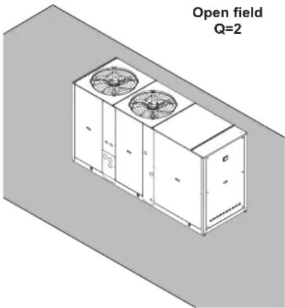
natural_image
Isometric view of an open field with two fans and control panels (no text or symbols on the diagram itself)Base setting up AB
| MOD. | SWL (dB)Octave bands (Hz) | SWL SPL dB(A) | |||||||||||
| 63 125 | 250 500 | 1000 2000 | 4000 8000 | dB dB(A)(E) 1 m 5 m 10 m | |||||||||
| 40.2 | 85,4 | 88,3 | 84,6 | 79,8 | 76,3 | 69,8 | 61,2 | 52,3 | 92 | 82 | 64 | 55 | 50 |
| 50.2 | 85,4 | 88,3 | 84,6 | 79,8 | 76,3 | 69,8 | 61,2 | 52,3 | 92 | 82 | 64 | 55 | 50 |
| 60.2 | 89,4 | 87,0 | 84,8 | 80,3 | 77,4 | 73,8 | 65,3 | 56,0 | 93 | 83 | 65 | 56 | 51 |
| 70.2 | 91,2 | 88,9 | 86,4 | 82,3 | 78,0 | 71,6 | 64,0 | 55,6 | 94 | 84 | 66 | 57 | 52 |
| 80.2 | 91,2 | 88,9 | 86,4 | 82,3 | 78,0 | 71,6 | 64,0 | 55,6 | 94 | 84 | 66 | 57 | 52 |
| 90.2 | 92,2 | 89,9 | 87,4 | 83,3 | 79,0 | 72,6 | 65,0 | 56,6 | 95 | 85 | 67 | 58 | 53 |
| 100.2 | 92,2 | 89,9 | 87,4 | 83,3 | 79,0 | 72,6 | 65,0 | 56,6 | 95 | 85 | 67 | 58 | 53 |
| 115.2 | 92,2 | 89,9 | 87,4 | 83,3 | 79,0 | 72,6 | 65,0 | 56,6 | 95 | 85 | 67 | 58 | 53 |
| 130.2 | 92,4 | 90,0 | 87,8 | 83,3 | 80,4 | 76,8 | 68,3 | 59,0 | 96 | 86 | 68 | 59 | 54 |
| 145.2 | 94,2 | 91,9 | 89,4 | 85,3 | 81,0 | 74,6 | 67,0 | 58,6 | 97 | 87 | 69 | 60 | 55 |
| 160.2 | 94,2 | 91,9 | 89,4 | 85,3 | 81,0 | 74,6 | 67,0 | 58,6 | 97 | 87 | 69 | 60 | 55 |
| 180.2 | 92,4 | 90,1 | 88,6 | 86,0 | 83,2 | 77,8 | 71,2 | 62,8 | 96 | 88 | 69 | 61 | 56 |
| 200.2 | 92,4 | 90,1 | 88,6 | 86,0 | 83,2 | 77,8 | 71,2 | 62,8 | 96 | 88 | 69 | 61 | 56 |
Low noise setting up AS
| MOD. | SWL (dB)Octave bands (Hz) | SWL SPL dB(A) | |||||||||||
| 63 125 | 250 500 | 1000 2000 | 4000 8000 | dB dB(A)(E) | 1 m 5 | m 10 m | |||||||
| 40.2 | 90,0 | 82,0 | 81,0 | 77,0 | 73,5 | 67,0 | 64,0 | 52,0 | 91 | 79 | 61 | 52 | 47 |
| 50.2 | 90,0 | 82,0 | 81,0 | 77,0 | 73,5 | 67,0 | 64,0 | 52,0 | 91 | 79 | 61 | 52 | 47 |
| 60.2 | 83,4 | 86,3 | 82,6 | 77,8 | 74,3 | 67,8 | 59,2 | 50,3 | 90 | 80 | 62 | 53 | 48 |
| 70.2 | 84,4 | 87,3 | 83,6 | 78,8 | 75,3 | 68,8 | 60,2 | 51,3 | 91 | 81 | 63 | 54 | 49 |
| 80.2 | 84,4 | 87,3 | 83,6 | 78,8 | 75,3 | 68,8 | 60,2 | 51,3 | 91 | 81 | 63 | 54 | 49 |
| 90.2 | 85,4 | 88,3 | 84,6 | 79,8 | 76,3 | 69,8 | 61,2 | 52,3 | 92 | 82 | 64 | 55 | 50 |
| 100.2 | 85,4 | 88,3 | 84,6 | 79,8 | 76,3 | 69,8 | 61,2 | 52,3 | 92 | 82 | 64 | 55 | 50 |
| 115.2 | 85,4 | 88,3 | 84,6 | 79,8 | 76,3 | 69,8 | 61,2 | 52,3 | 92 | 82 | 64 | 55 | 50 |
| 130.2 | 89,4 | 87,0 | 84,8 | 80,3 | 77,4 | 73,8 | 65,3 | 56,0 | 93 | 83 | 65 | 56 | 51 |
| 145.2 | 91,2 | 88,9 | 86,4 | 82,3 | 78,0 | 71,6 | 64,0 | 55,6 | 94 | 84 | 66 | 57 | 52 |
| 160.2 | 91,2 | 88,9 | 86,4 | 82,3 | 78,0 | 71,6 | 64,0 | 55,6 | 94 | 84 | 66 | 57 | 52 |
| 180.2 | 92,2 | 89,9 | 87,4 | 83,3 | 79,0 | 72,6 | 65,0 | 56,6 | 95 | 85 | 66 | 58 | 53 |
| 200.2 | 92,2 | 89,9 | 87,4 | 83,3 | 79,0 | 72,6 | 65,0 | 56,6 | 95 | 85 | 66 | 58 | 53 |
Extra low noise setting up AX
| MOD. | SWL (dB)Octave bands (Hz) | SWL SPL dB(A) | |||||||||||
| 63 125 | 250 500 | 1000 2000 | 4000 8000 | dB dB(A)(E) 1 m 5 m 10 m | |||||||||
| 40.2 | 82,6 | 83,6 | 80,2 | 74,8 | 71,0 | 65,5 | 59,4 | 53,6 | 88 | 77 | 59 | 50 | 45 |
| 50.2 | 82,6 | 83,6 | 80,2 | 74,8 | 71,0 | 65,5 | 59,4 | 53,6 | 88 | 77 | 59 | 50 | 45 |
| 60.2 | 89,0 | 81,0 | 80,0 | 76,0 | 72,0 | 67,0 | 62,0 | 52,0 | 90 | 78 | 60 | 51 | 46 |
| 70.2 | 90,0 | 82,0 | 81,0 | 77,0 | 73,5 | 67,0 | 64,0 | 52,0 | 91 | 79 | 61 | 52 | 47 |
| 80.2 | 90,0 | 82,0 | 81,0 | 77,0 | 73,5 | 67,0 | 64,0 | 52,0 | 91 | 79 | 61 | 52 | 47 |
| 90.2 | 83,4 | 86,3 | 82,6 | 77,8 | 74,3 | 67,8 | 59,2 | 50,3 | 90 | 80 | 62 | 53 | 48 |
| 100.2 | 83,4 | 86,3 | 82,6 | 77,8 | 74,3 | 67,8 | 59,2 | 50,3 | 90 | 80 | 62 | 53 | 48 |
| 115.2 | 83,4 | 86,3 | 82,6 | 77,8 | 74,3 | 67,8 | 59,2 | 50,3 | 90 | 80 | 62 | 53 | 48 |
| 130.2 | 84,4 | 87,3 | 83,6 | 78,8 | 75,3 | 68,8 | 60,2 | 51,3 | 91 | 81 | 63 | 54 | 49 |
| 145.2 | 85,4 | 88,3 | 84,6 | 79,8 | 76,3 | 69,8 | 61,2 | 52,3 | 92 | 82 | 64 | 55 | 50 |
| 160.2 | 85,4 | 88,3 | 84,6 | 79,8 | 76,3 | 69,8 | 61,2 | 52,3 | 92 | 82 | 64 | 55 | 50 |
| 180.2 | 89,4 | 87,0 | 84,8 | 80,3 | 77,4 | 73,8 | 65,3 | 56,0 | 93 | 83 | 64 | 56 | 51 |
| 200.2 | 89,4 | 87,0 | 84,8 | 80,3 | 77,4 | 73,8 | 65,3 | 56,0 | 93 | 83 | 64 | 56 | 51 |
(E): Data declared according to EUROVENT LCP certification programme. The values are for units without options and accessories.
OPERATING RANGE
Operating range
The table below lists the operating ranges within which correct operation of the units is guaranteed, depending on the Version and Operating Mode available for each type of unit.
Remember that in Heat Pump units, heat recovery only takes place during operation in the cooling mode.
NOTE: the admissible limits for water flow rate on heat exchangers are indicated under the related pressure drop graph (see section "water pressure drop"). If the unit is equipped with pumping module the admissible limits are indicated under the related working head graph (see section "working head").
Operating range of Base version
| Thermal gradient of the water Limit value | ||
| Minimum °C 3 | ||
| Maximum °C 8 | ||
| Verify that water flow rate is inside the admissible limits. | ||
IN COOLING MODE
UNIT MEDIUM TEMPERATURE - 0 M 5

area
| Temperature Range (°C B.S.) | Value | | ---------------------------- | ----- | | 0 - 10 | 25 | | 10 - 35 | 25 | | 35 - 48 | 7 | | 48 - 55 | 7 |UNIT HIGH TEMPERATURE - 0 A 5
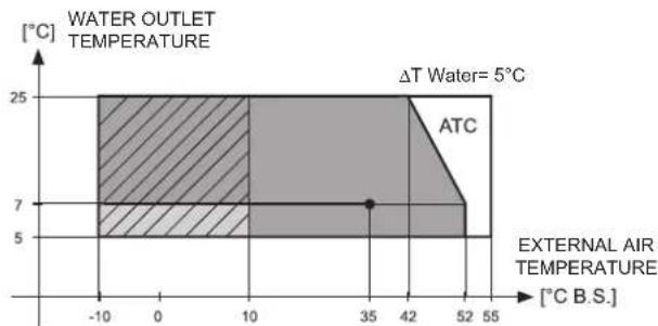
area
| Temperature Range [°C B.S.] | Value | | --------------------------- | ----- | | 0 to 55 | 25 | | 55 to 100 | 25 | | 100 to 150 | 25 | | 150 to 200 | 25 | | 200 to 250 | 25 | | 250 to 300 | 25 | | 300 to 350 | 25 | | 350 to 400 | 25 | | 400 to 450 | 25 | | 450 to 500 | 25 | | 500 to 550 | 25 |
With accessory fans modulating control

With accessory fans modulating control (brine is recommended)

ATC (Advanced Temperature Control) function may occur, if present
IN HEATING MODE
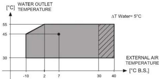
area
| Temperature Range (°C B.S.) | Value | | ---------------------------- | ----- | | -10 to 2 | 45 | | 2 to 7 | 45 | | 30 to 40 | 55 |
With accessory fans modulating control
BRINE UNIT BR - BP - IN COOLING MODE
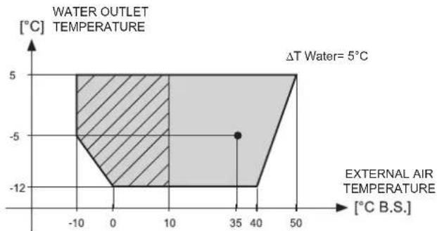
area
| External Air Temperature [°C B.S.] | Water Outlet Temperature [°C] | | ----------------------------------- | ------------------------------ | | -10 | -5 | | 0 | -12 | | 35 | -5 | | 40 | -12 | | 50 | 5 |
With accessory fans modulating control (brine is mandatory)

Brine is mandatory
Plant side exchanger
The graph below illustrates the water pressure drop values in kPa depending on the flow rate in liters/second. The operating range is delimited by the minimum and maximum values given in the next table. The graphs are referred to units operating with water at the temperature of 10°C (density 1000kg / m3 ).

Operating range
| MODELS | 40.2 | 50.2 | 60.2 | 70.2 | 80.2 | 90.2 | 100.2 | 115.2 | 130.2 | 145.2 | 160.2 | 180.2 | 200.2 | UM | NOTE | |
| Graphic refer 1 1 2 3 4 | 5 6 7 8 | 9 10 11 | 12 - | Q= Water flow rate ΔP = Water pressure drop | ||||||||||||
| Lower limit value | Q 1,3 | 3 1,33 | 1,47 1,78 | 2,05 2, | 43 2,78 | 3,12 3,38 | 3,87 | 4,20 4,79 | 5,24 I\ | |||||||
| \Delta p15 | kPa | |||||||||||||||
| Upper limit value | Q 4,1 | 9 4,19 | 4,64 5,64 | 6,49 7, | 68 8,79 | 9,86 10, | 7 12,2 | 13,3 15,2 | 16,6 I\ | |||||||
| Δp 150 | ||||||||||||||||
Desuperheaters
The graph below illustrates the water pressure drop values in kPa depending on the flow rate in liters/second. The operating range is delimited by the minimum and maximum values given in the next table. The graphs are referred to units operating with water at the temperature of 10°C (density 1000kg / m3 ).

line
| Water flow rate (l/s) | Curve 1 | Curve 2 | Curve 3 | Curve 4 | | --------------------- | ------- | ------- | ------- | ------- | | 0.50 | 5 | 5 | 5 | 5 | | 0.75 | 10 | 8 | 6 | 4 | | 1.00 | 15 | 12 | 9 | 6 | | 1.25 | 20 | 16 | 12 | 8 | | 1.50 | 25 | 20 | 15 | 10 | | 1.75 | 30 | 24 | 18 | 12 | | 2.00 | 35 | 28 | 21 | 14 | | 2.25 | 40 | 32 | 24 | 16 | | 2.50 | 45 | 36 | 27 | 18 | | 2.75 | 50 | 40 | 30 | 20 | | 3.00 | 55 | 44 | 33 | 22 | | 3.25 | 60 | 48 | 36 | 24 | | 3.50 | 65 | 52 | 39 | 26 |Operating range
| MODELS | 40.2 | 50.2 | 60.2 | 70.2 | 80.2 | 90.2 | 100.2 | 115.2 | 130.2 | 145.2 | 160.2 | 180.2 | 200.2 | UM | NOTE | |
| Graphic refer 1 1 1 1 1 | 2 2 2 3 | 3 3 4 4 - | Q= Water flow rate ΔP = Water pressure drop | |||||||||||||
| Lower limit value | Q 0,5 | 7 0,57 | 0,57 0,57 | 0,57 0, | 76 0,76 | 0,76 1, | 1 1,11 | 1,11 1,41 | 1,41 s | |||||||
| Δp | 5 | kPa | ||||||||||||||
| Upper limit value | Q | 3,11 3, | 11 3,11 | 3,11 3, | 11 3,50 | 3,50 3,50 | 3,50 3,50 | 3,50 3,50 | 3,50 3,50 | 50 s | ||||||
| Δp | 150 | kPa | ||||||||||||||
Total recovery exchanger
The graph below illustrates the water pressure drop values in kPa depending on the flow rate in liters/second. The operating range is delimited by the minimum and maximum values given in the next table. The graphs are referred to units operating with water at the temperature of 10°C (density 1000kg / m3 ).
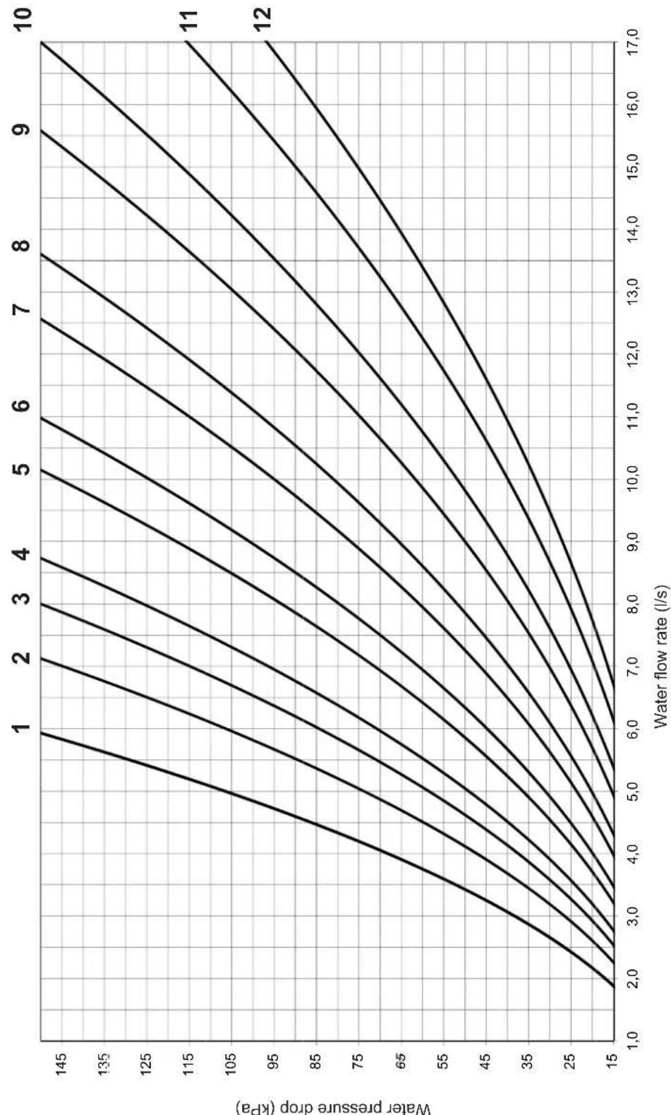
Operating range
| MODELS | 40.2 | 50.2 | 60.2 | 70.2 | 80.2 | 90.2 | 100.2 | 115.2 | 130.2 | 145.2 | 160.2 | 180.2 | 200.2 | UM | NOTE | |
| Graphic refer 1 1 2 3 4 | 5 6 7 8 | 9 10 11 | 12 - | Q= Water flow rate ΔP = Water pressure drop | ||||||||||||
| Lower limit value | Q 1,8 | 8 1,89 | 2,25 2,53 | 2,76 3 | 21 3,47 | 3,97 4,30 | 4,93 | 5,38 6,13 | 6,69 I/s | |||||||
| Δp | 15 | kPa | ||||||||||||||
| Upper limit value | Q | 5,93 | 5,97 | 7,13 | 8,00 | 8,73 | 10,1 | 11,0 | 12,6 | 13,6 | 15,6 | 17,0 | 17,0 | 17,0 | I/s | |
| Δp | 150 | kPa | ||||||||||||||
Standard working head pumps
Working head is that at the pumping module outlet reduced by all pressure losses inside the unit. The graph below illustrates for the pumping module the working head values in kPa depending on the flow rate in liters/second. The operating range is delimited by the minimum and maximum values given in the next table. The graphs are referred to units operating with water at the temperature of 10°C (density 1000kg / m3 ).

Operating range
| MODELS | 40.2 | 50.2 | 60.2 | 70.2 | 80.2 | 90.2 | 100.2 | 115.2 | 130.2 | 145.2 | 160.2 | 180.2 | 200.2 | UM | NOTE | |
| Graphic refer 1 1 2 3 4 | 5 6 7 8 | 9 10 11 | 12 - | Q= Water flow rate | ||||||||||||
| Lower limit value | Q | 1,33 1,33 1,47 | 1,78 2,05 2,43 | 2,78 3,1 | 2 3,38 3,87 4,20 | 4,79 5,24 I/s | ||||||||||
| Upper limit value | Q | 3,85 3,85 4,00 | 4,36 4,61 7,00 | 7,29 7,48 7,80 9,32 9,58 | 11,3 11,4 I/s | |||||||||||
High working head pumps
Working head is that at the pumping module outlet reduced by all pressure losses inside the unit. The graph below illustrates for the pumping module the working head values in kPa depending on the flow rate in liters/second. The operating range is delimited by the minimum and maximum values given in the next table. The graphs are referred to units operating with water at the temperature of 10°C (density 1000kg / m3 ).
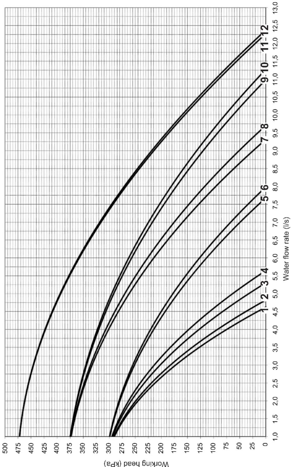
line
| Water flow rate (l/s) | Working head (kPa) | | --------------------- | ------------------ | | 1.0 | 475 | | 1.5 | 460 | | 2.0 | 445 | | 2.5 | 430 | | 3.0 | 415 | | 3.5 | 400 | | 4.0 | 385 | | 4.5 | 370 | | 5.0 | 355 | | 5.5 | 340 | | 6.0 | 325 | | 6.5 | 310 | | 7.0 | 295 | | 7.5 | 280 | | 8.0 | 265 | | 8.5 | 250 | | 9.0 | 235 | | 9.5 | 220 | | 10.0 | 205 | | 10.5 | 190 | | 11.0 | 175 | | 11.5 | 160 | | 12.0 | 145 | | 12.5 | 130 | | 13.0 | 115 |Operating range
| MODELS | 40.2 | 50.2 | 60.2 | 70.2 | 80.2 | 90.2 | 100.2 | 115.2 | 130.2 | 145.2 | 160.2 | 180.2 | 200.2 | UM | NOTE | |
| Graphic refer 1 1 2 3 4 | 5 6 7 8 | 9 10 11 | 12 - | Q= Water flow rate | ||||||||||||
| Lower limit value | Q | 1,33 1,33 1,47 | 1,78 2,05 2,43 | 2,78 3,1 | 2 3,38 3,87 4,20 | 4,79 5,24 \s | ||||||||||
| Upper limit value | Q | 4,62 4,62 4,82 | 5,30 5,64 7,68 | 7,98 9,3 | 1 9,70 11,0 11,3 | 12,3 12,4 \s | ||||||||||
DIMENSIONAL AND PHYSICAL DATA
Overall dimensions
Mod. 40-50-60-70-80

Mod. 90-100-115

Mod. 130-145-160

Mod. 180-200
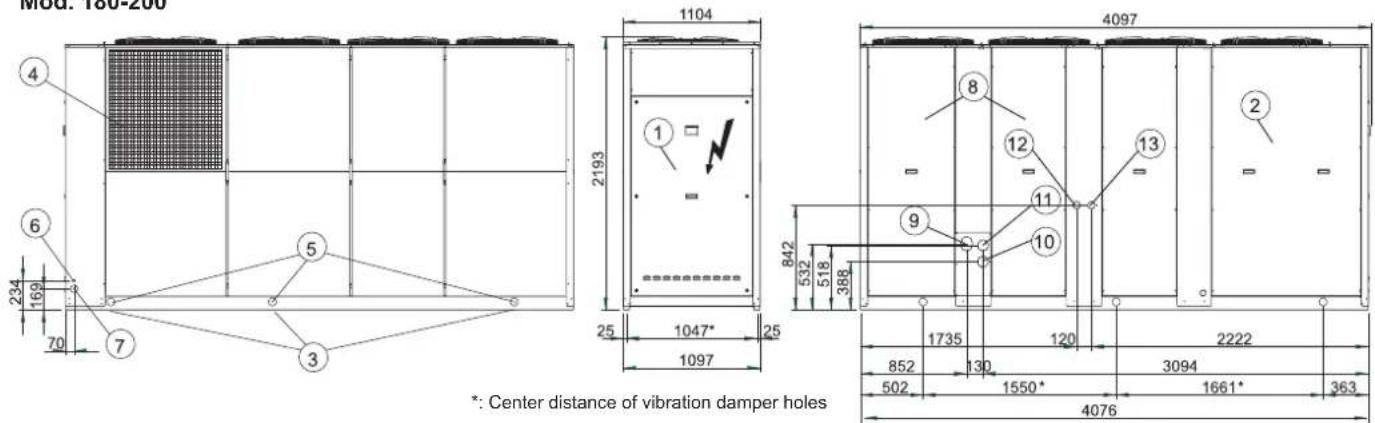
DIMENSIONAL AND PHYSICAL DATA
Description of the components
1 - Access panel to electric panel's power section
2 - Access panel to compressor compartment
3 - Vibration damper fixing holes (4 pcs)
4 - Coil protection grilles (accessory)
5 - ø 65 mm lifting holes
6 - ∅ 22 mm input hole for accessory cables
7-ø 60 mm hole for electric power supply input
8 - Access panel to pump compartment
9 - Water inlet for AM SS
10 - Water inlet for PS
11 - Water outlet
12 - Water inlet for Desuperheater (VD)
13 - Water outlet for Desuperheater (VD)
14 - Water inlet for Total recovery (VR)
15 - Water outlet for Total recovery (VR)
16 - Water inlet for plant exchanger
17 - Water outlet for plant exchanger
Note (1): Victaulic connections Kit do not allow external connections.
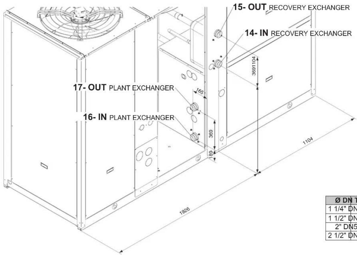
| ∅ DN Type |
| 1 1/4" DN32 Victaulic |
| 1 1/2" DN40 Victaulic |
| 2" DN50 Victaulic |
| 2 1/2" DN65 Victaulic |
| STANDARD UNIT | VICTAULIC CONNECTIONS | PIPE KIT WITHOUT TANK MKT SS | MP AM MP SS | MP PS VD VR | |||||||
| PIPE KIT WITH TANK MKT AM | |||||||||||
| IN OUT IN OUT | IN OUT IN OUT IN OUT IN OUT IN OUT | ||||||||||
| Mod. | ∅ Rif. | ∅ Rif. | ∅ Rif. | Rif. | ∅ Rif. | ∅ Rif. | ∅ Rif. | ∅ Rif. | Rif. | ∅ Rif. | ∅ Rif. | ∅ Rif. | ∅ Rif. | ∅ Rif. | ∅ Rif. | ∅ Rif. | ∅ Rif. | ∅ Rif. | ∅ Rif. | ∅ Rif. | ∅ Rif. | ∅ Rif. | ∅ Rif. | ∅ Rif. | ∅ Rif. | ∅ Rif. | ∅ Rif. | ∅ Rif. | ∅ Rif. | ∅ Rif. | ∅ Rif. | ∅ Rif. | ∅ Rif. | ∅ Rif. | ∅ Riv. | ∅ Riv. | ∅ Riv. | ∅ Riv. | ∅ Riv. | ∅ Riv. | ∅ Riv. | ∅ Riv. | ∅ Riv. | ∅ Riv. | ∅ Riv. | ∅ Riv. | ∅ Riv. | ∅ Riv. | ∅ Riv. | ∅ Riv. | ∅ Riv. | ∅ Riv. | ∅ Riv. | ∅ Riv. | ∅ Riv. | ∅ Riv. | ∅ Riv. | ∅ Riv. | ∅ Riv. | ∅ Rif. | ∅ Rif. | ∅ Rif. | ∅ Rif. | ∅ Rif. | ∅ Rif. | ∅ Rif. | ∅ Rif. | ∅ Rif. | ∅ Rif. | ∅ Rif. | ∅ Rif. | ∅ Rif. | ∅ Rif. | ∅ Rif. | ∅ Rif. | ∅ Rif. | ∅ Rif. | ∅ Rif. | ∅ Rif. | ∅ Rif. | ∅ Rif. | ∅ Rif. | ∅ Rif. | ∅rif. | ∅ rif. | ∅ rif. | ∅ rif. | ∅ rif. | ∅ rif. | ∅ rif. | ∅ rif. | ∅ rif. | ∅ rif. | ∅ rif. | ∅ rif. | ∅ rif. | ∅ rif. | ∅ rif. | ∅ rif. | ∅ rif. | ∅ rif. | ∅ rif. | ∅ rif. | ∅ rif. | ∅ rif. | ∅ rif. | ∅ rif. | ∅ rif. | ∅ rif. | ∅rif. | ∅ rif. | ∅ rif. | ∅ rif. | ∅ rif. | ∅ rif. | ∅ rif. | ∅ rif. | ∅ rif. | ∅ rif. | ∅ rif. | ∅ rif. | ∅ rif. | ∅ rif. | ∅ rif. | ∅ rif. | ∅ rif. | ∅ rif. | ∅ rif. | ∅ rif. | ∅ rif. | ∅ rif. | ∅ rif. | ∅ rif. | ∅rif. | ∅rif. | ∅rif. | ∅rif. | ∅rif. | ∅rif. | ∅rif. | ∅rif. | ∅rif. | ∅rif. | ∅rif. | ∅rif. | ∅rif. | ∅rif. | ∅rif. | ∅rif. | ∅rif. | ∅rif. | ∅rif. | ∅rif. | ∅rif. | ∅rif. | ∅rif. | ∅rif. | ∅rif. | ∅ rif. | ∅ rif. | ∅ rif. | ∅ rif. | ∅ rif. | ∅ rif. | ∅ rif. | ∅ rif. | ∅ rif. | ∅ rif. | ∅ rif. | ∅ rif. | ∅ rif. | ∅ rif. | ∅ rif. | ∅ rif. | ∅ rif. | ∅ rif. | ∅ rif. | ∅ rif. | ∅ rif. | ∅ rif. | ∅ rif. | ∅ rif. | ∅ rif. | ∅ rif. | ∅ rif. | ∅ rif. | ∅ rif. | ∅ rif. | ∅ rif. | ∅ rif. | ∅ rif. | ∅ rif. | ∅ rif. | ∅ rif. | ∅ rif. | ∅ rif. | ∅ rif. | ∅ rif. | ∅ rif. | ∅ rif. | ∅ rif. | ∅ rif. | ∅ rif. | ∅ rif. | ∅ rif. | ∅ rif. | ∅ rif. | rif. | ∅ rif. | ∅ rif. | ∅ rif. | ∅ rif. | ∅ rif. | ∅ rif. | ∅ rif. | ∅ rif. | ∅ rif. | ∅ rif. | ∅ rif. | ∅ rif. | ∅ rif. | ∅ rif. | ∅ rif. | ∅ rif. | ∅ rif. | ∅ rif. | ∅ rif. | ∅ rif. | ∅ rif. | ∅ rif. | ∅ rif. | ∅ rif. | rif. | ∅ rif. | ∅ rif. | ∅ rif. | ∅ rif. | ∅ rif. | ∅ rif. | ∅ rif. | ∅ rif. | ∅ rif. | ∅ rif. | ∅ rif. | ∅ rif. | ∅ rif. | ∅ rif. | ∅ rif. | ∅ rif. | ∅ rif. | ∅ rif. | ∅ rif. | ∅ rif. | ∅ rif. | ∅ rif. | rif. | |||||||||||||||||||||||||||||||||||||||||||||||||||||||||||||||||||||||||||||||||||||||||||||||||||||||||||||||||||||||||||||||||||||||||||||||||||||||||||||||||||||||||||||||||||||||||||||||||||||||||||||||||||||||||||||||||||||||||||||||||||||||||||||||||||||||||||||||||||||||||||||||||||||||||||||||||||||||||||||||||||||||||||||
| 40 | 1 1/4" | 16 | 1 1/4" | 17 | 2" | 16 | 2" | 17 | 2" | 10 | 2" | 11 | 2" | 9 | 2" | 11 | 2" | 10 | 2" | 11 | 2" | 10 | 2" | 11 | 2" | 10 | 2" | 11 | 2" | 10 | 2" | 11 | 2" | 10 | 2" | 11 | 2" | 10 | 2" | 11 | 2" | 10 | 2" | 11 | 2" | 10 | 2" | 11 | 2" | 10 | 2" | ||||||||||||||||||||||||||||||||||||||||||||||||||||||||||||||||||||||||||||||||||||||||||||||||||||||||||||||||||||||||||||||||||||||||||||||||||||||||||||||||||||||||||||||||||||||||||||||||||||||||||||||||||||||||||||||||||||||||||||||||||||||||||||||||||||||||||||||||||||||||||||||||||||||||||||||||||||||||||||||||||||||||||||||||||||||||||||||||||||||||||||||||||||||||||||||||||||||||||||||||||||||||||||||||||||||||||||||||||||||||||||||||||||||||||||||||||||||||||||||||||||||||||||||||||||||||||||||||||||||||||||||||||||||||||
| 50 | |||||||||||||||||||||||||||||||||||||||||||||||||||||||||||||||||||||||||||||||||||||||||||||||||||||||||||||||||||||||||||||||||||||||||||||||||||||||||||||||||||||||||||||||||||||||||||||||||||||||||||||||||||||||||||||||||||||||||||||||||||||||||||||||||||||||||||||||||||||||||||||||||||||||||||||||||||||||||||||||||||||||||||||||||||||||||||||||||||||||||||||||||||||||||||||||||||||||||||||||||||||||||||||||||||||||||||||||||||||||||||||||||||||||||||||||||||||||||||||||||||||||||||||||||||||||||||||||||||||||||||||||||||||||||||||||||||||||||||||||||||||||||||||||||||||||||||||
| 60 | ∅ rif. | ∅ rif. | ∅ rif. | ∅ rif. | ∅ rif. | ∅ rif. | ∅ rif. | ∅ rif. | ∅ rif. | ∅ rif. | ∅ rif. | ∅ rif. | ∅ rif. | ∅ rif. | ∅ rif. | ∅ rif. | ∅ rif. | ∅ rif. | ∅ rif. | ∅ rif. | ∅ rif. | ∅ rif. | ∅ rif. | ∅ rif. | ∅ rif, | ∅ rif. | ∅ rif. | ∅ rif. | ∅ rif. | ∅ rif. | ∅ rif. | ∅ rif. | ∅ rif. | ∅ rif. | ∅ rif. | ∅ rif. | ∅ rif. | ∅ rif. | ∅ rif. | ∅ rif. | ∅ rif. | ∅ rif. | ∅ rif. | ∅ rif. | ∅ rif. | ∅ rif. | ∅ rif. | ∅ rif. | ∅ rif. | ∅ rif | ∅ rif. | ∅ rif. | ∅ rif. | ∅ rif. | ∅ rif. | ∅ rif. | ∅ rif. | ∅ rif. | ∅ rif. | ∅ rif. | ∅ rif. | ∅ rif. | ∅ rif. | ∅ rif. | ∅ rif. | ∅ rif. | ∅ rif. | ∅ rif. | ∅ rif. | ∅ rif. | ∅ rif. | ∅ rif. | ∅ rif. | ∅ rif. | ∅ rif.(2) | ∅ rif.(2) | ∅ rif.(2) | ∅ rif.(2) | ∅ rif.(2) | ∅ rif.(2) | ∅ rif.(2) | ∅ rif.(2) | ∅ rif.(2) | ∅ rif.(2) | ∅ rif.(2) | ∅ rif.(2) | ∅ rif.(2) | ∅ rif.(2) | ∅ rif.(2) | ∅ rif.(2) | ∅ rif.(2) | ∅ rif(2) | ∅ rif.(2) | ∅ rif.(2) | ∅ rif.(2) | ∅ rif.(2) | ∅ rif.(2) | ∅ rif.(2) | ∅ rif.(2) | ∅ rif.(2) | ∅ rif.(2) | ∅ rif.(2) | ∅ rif.(2) | ∅ rif.(2) | ∅ rif.(2) | ∅ rif.(2) | ∅ rif.(2) | ∅ rif.(2) | rif.(2) | ∅ rif.(2) | ∅ rif.(2) | ∅ rif.(2) | ∅ rif.(2) | ∅ rif.(2) | ∅ rif.(2) | ∅ rif.(2) | ∅ rif.(2) | ∅ rif.(2) | ∅ rif.(2) | ∅ rif.(2) | ∅ rif.(2) | ∅ rif.(2) | ∅ rif.(2) | ∅ rif.(2) | ∅ rif.(2)(2) | ∅ rif.(2) | ∅ rif.(2) | ∅ rif.(2) | ∅ rif.(2) | ∅ rif.(2) | ∅ rif.(2) | ∅ rif.(2) | ∅ rif.(2) | ∅ rif.(2) | ∅ rif.(2) | ∅ rif.(2) | ∅ rif.(2) | ∅ rif.(2) | ∅ rif.(2) | ∅ rif.(2) | ∅ rif.(2) | # rif.(2) | ∅ rif.(2) | ∅ rif.(2) | ∅ rif.(2) | ∅ rif.(2) | ∅ rif.(2) | ∅ rif.(2) | ∅ rif.(2) | ∅ rif.(2) | ∅ rif.(2) | ∅ rif.(2) | ∅ rif.(2) | ∅ rif.(2) | ∅ rif.(2) | ∅ rif.(2) | ∅ rif.(2) | ∅ rif.(2)* | ∅ rif.(2) | ∅ rif.(2) | ∅ rif.(2) | ∅ rif.(2) | ∅ rif.(2) | ∅ rif.(2) | ∅ rif.(2) | ∅ rif.(2) | ∅ rif.(2) | ∅ rif.(2) | ∅ rif.(2) | ∅ rif.(2) | ∅ rif.(2) | ∅ rif.(2) | ∅ rif.(2) | ∅ rif.(2) | ∅ rif*(2) | ∅ rif.(2) | ∅ rif.(2) | ∅ rif.(2) | ∅ rif.(2) | ∅ rif.(2) | ∅ rif.(2) | ∅ rif.(2) | ∅ rif.(2) | ∅ rif.(2) | ∅ rif.(2) | ∅ rif.(2) | ∅ rif.(2) | ∅ rif.(2) | ∅ rif.(2) | ∅ rif.(2) | ∅ rif.(2) | rif. | ∅ rif.(2) | ∅ rif.(2) | ∅ rif.(2) | ∅ rif.(2) | ∅ rif.(2) | ∅ rif.(2) | ∅ rif.(2) | ∅ rif.(2) | ∅ rif.(2) | ∅ rif.(2) | ∅ rif.(2) | ∅ rif.(2) | ∅ rif.(2) | ∅ rif.(2) | ∅ rif.(2) | ∅ rif.(2) | ∅ rif. | ∅ rif.(2) | ∅ rif.(2) | ∅ rif.(2) | ∅ rif.(2) | ∅ rif.(2) | ∅ rif.(2) | ∅ rif.(2) | ∅ rif.(2) | ∅ rif.(2) | ∅ rif.(2) | ∅ rif.(2) | ∅ rif.(2) | ∅ rif.(2) | ∅ rif.(2) | ∅ rif.(2) | ∅ rif.(2)* | ∅ rif. | ∅ rif.(2) | ∅ rif.(2) | ∅ rif.(2) | ∅ rif.(2) | ∅ rif.(2) | ∅ rif.(2) | ∅ rif.(2) | ∅ rif.(2) | ∅ rif.(2) | ∅ rif.(2) | ∅ rif.(2) | ∅ rif.(2) | ∅ rif.(2) | ∅ rif.(2) | ∅ rif.(2) | ∅ rif.(2* | ∅ rif.(2) | ∅ rif.(2) | ∅ rif.(2) | ∅ rif.(2) | ∅ rif.(2) | ∅ rif.(2) | ∅ rif.(2) | ∅ rif.(2) | ∅ rif.(2) | ∅ rif.(2) | ∅ rif.(2) | ∅ rif.(2) | ∅ rif.(2) | ∅ rif.(2) | ∅ rif.(2) | ∅ rif.(2) | ∅ rif (2) | ∅ rif.(2) | ∅ rif.(2) | ∅ rif.(2) | ∅ rif.(2) | ∅ rif.(2) | ∅ rif.(2) | ∅ rif.(2) | ∅ rif.(2) | ∅ rif.(2) | ∅ rif.(2) | ∅ rif.(2) | ∅ rif.(2) | ∅ rif.(2) | ∅ rif.(2) | ∅ rif.(2) | ∅ rif.(2) | %rif.(2) | %rif.(2) | %rif.(2) | %rif.(2) | %rif.(2) | %rif.(2) | %rif.(2) | %rif.(2) | %rif.(2) | %rif.(2) | %rif.(2) | %rif.(2) | %rif.(2) | %rif.(2) | %rif.(2) | %rif.(2) | %rif.(2) | |||||||||||||||||||||||||||||||||||||||||||||||||||||||||||||||||||||||||||||||||||||||||||||||||||||||||||||||||||||||||||||||||||||||||||||||||||||||||||||||||||||||||||||||||||||||||||||||||||||||||||||||||||||||||||||||||||||||||||||||||||||||||||||||||||||||||||||||||||||||||||||||||||||||||
DIMENSIONAL AND PHYSICAL DATA
Minimum space required for operation
To correctly install the unit, comply with the measurements for the free area that must be left around the unit, as shown in the figure. This will ensure good air circulation, allow the unit to operate correctly and facilitate future maintenance work.
The distances must be doubled if the unit is to be installed in a pit.
NOTE. Allow for an uncluttered area of not less than 2.5 meters above the unit.

| Mod. 40÷115 130÷200 UM | ||
| E 1600 2000 mm |
Position of condensate drain
The condensate tray (if present) must have a suitable drain trap to prevent spilling of water during operation.
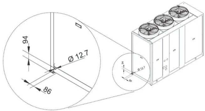
Vibration-damper installation
To prevent the operating unit from transmitting vibrations to the bearing structure, vibration dampening materials should be inserted under the bearing points.
The unit can be supplied with the rubber or spring vibration dampening accessory. This must be mounted by the installer.

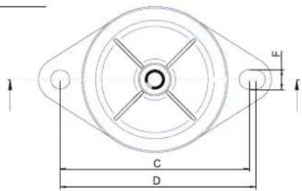
| Unit | Mod. | A | B | C | D | E | F | G | UM |
| Unit without tank | 40-80 | 95 | 35 | 122 | 124 | 150 | 10 | 3 | mm |
| 90-160 | 106 | 37 | 136 | 150 | 170 | 12,5 | 3,5 | mm | |
| 180-200 | 95 | 35 | 122 | 124 | 150 | 10 | 3 | mm | |
| Unit with tank | 40-80 | 95 | 35 | 122 | 124 | 150 | 10 | 3 | mm |
| 90-200 | 106 | 37 | 136 | 150 | 170 | 12,5 | 3,5 | mm |
Area of support
Mod. 40-50-60-70-80 Mod. 90-100-115-130-145-160 Mod. 180-200

To correctly install the unit, comply with the measurements for the free area that must be left around the unit, as shown in the drawing.
Mod. 40-50-60-70-80-90-100-115-130-145-160

Mod. 180-200
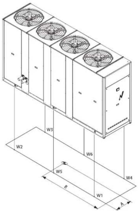
DIMENSIONAL AND PHYSICAL DATA
Transport weight
UNIT WITHOUT WATER STORAGE TANK
Unit WITHOUT Hydronic kit
IR version
| Acoustic version | AB-AS AX | |||||
| Models | Center of gravity position [mm] | Weight [Kg] | Center of gravity position [mm] | Weight [Kg] | ||
| A B A | B A B A B | |||||
| 40.2 401 | 890 565 41 | 9 906 587 | 40.2 41 | 4 872 597 | 430 888 619 | |
| 50.2 401 | 888 567 41 | 9 904 589 | 50.2 41 | 4 870 599 | 430 886 621 | |
| 60.2 403 | 878 592 42 | 1 894 614 | 60.2 41 | 6 860 624 | 432 876 646 | |
| 70.2 414 | 883 630 42 | 4 894 646 | 70.2 42 | 4 865 663 | 434 875 679 | |
| 80.2 419 | 887 656 41 | 9 887 663 | 80.2 43 | 0 871 688 | 430 871 695 | |
| 90.2 467 | 1199 893 4 | 84 1213 91 | 3 90.2 | 478 1180 | 932 494 119 | 4 952 |
| 100.2 449 | 1146 973 | 465 1160 99 | 3 100. | 2 460 1130 | 1012 475 | 1144 10 |
| 115.2 | 455 | 1158 | 1023 | 482 | 1180 | 1112 |
| 130.2 | 458 | 1152 | 1110 | 476 | 1168 | 1138 |
| 145.2 | 457 | 1141 | 1163 | 475 | 1156 | 1191 |
| 160.2 | 470 | 1150 | 1211 | 470 | 1150 | 1223 |
| 180.2 | 465 | 1389 | 1356 | 480 | 1407 | 1389 |
| 200.2 | 477 | 1399 | 1400 | 477 | 1399 | 1414 |
IP version
| Acoustic version | AB-AS AX | |||||
| Models | Center of gravity position [mm] | Weight [Kg] | Center of gravity position [mm] | Weight [Kg] | ||
| 2 | ||||||
| 115.2 | 466 | 1142 | 1062 | 492 | 1165 | 1155 |
| 130.2 | 469 | 1138 | 1153 | 486 | 1153 | 1182 |
| 145.2 | 468 | 1128 | 1210 | 485 | 1143 | 1238 |
| 160.2 | 480 | 1137 | 1260 | 480 | 1137 | 1273 |
| 180.2 | 474 | 1368 | 1407 | 488 | 1386 | 1440 |
| 200.2 | 486 | 1378 | 1451 | 486 | 1378 | 1466 |
Unit WITH Hydronic kit
IR version
IP version
| Acoustic version | AB-AS AX | ||||||
| Models | Center of gravity position [mm] | Weight [Kg] | Center of gravity position [mm] | Weight [Kg] | |||
| A B A | B A B A B | ||||||
| 40.2 364 | 1048 680 3 | 80 | 1057 70 | 2 40.2 | 376 1026 7 | 12 391 103 | 5 734 |
| 50.2 364 | 1046 682 3 | 80 | 1055 70 | 4 50.2 | 376 1024 7 | 14 391 103 | 3 736 |
| 60.2 366 | 1036 707 3 | 82 | 1045 72 | 9 60.2 | 378 1014 7 | 39 393 102 | 3 761 |
| 70.2 377 | 1032 745 3 | 86 | 1038 76 | 1 70.2 | 387 1011 7 | 78 397 101 | 7 794 |
| 80.2 383 | 1031 770 3 | 83 | 1031 77 | 8 80.2 | 393 1011 8 | 03 393 101 | 1 811 |
| 90.2 | 432 | 1375 | 1037 | 446 | 1384 | 1057 | |
| 100.2 | 419 | 1316 | 1117 | 432 | 1325 | 1137 | |
| 115.2 | 425 | 1328 | 1167 | 448 | 1338 | 1267 | |
| 130.2 | 427 | 1314 | 1266 | 444 | 1324 | 1294 | |
| 145.2 | 428 | 1297 | 1318 | 444 | 1308 | 1347 | |
| 160.2 | 440 | 1300 | 1367 | 440 | 1300 | 1381 | |
| 180.2 | 432 | 1615 | 1555 | 445 | 1626 | 1588 | |
| 200.2 | 444 | 1617 | 1599 | 444 | 1617 | 1615 | |
| Acoustic version | AB-AS AX | |||||
| Models | Center of gravity position [mm] | Weight [Kg] | Center of gravity position [mm] | Weight [Kg] | ||
| 90.2 | 443 | 1352 | 1076 | 456 | 1361 | 1096 |
| 100.2 | 429 | 1296 | 1156 | 442 | 1305 | 1176 |
| 115.2 | 435 | 1308 | 1206 | 458 | 1319 | 1311 |
| 130.2 | 438 | 1296 | 1309 | 454 | 1306 | 1338 |
| 145.2 | 439 | 1281 | 1366 | 454 | 1291 | 1394 |
| 160.2 | 450 | 1283 | 1416 | 450 | 1283 | 1430 |
| 180.2 | 441 | 1589 | 1606 | 454 | 1601 | 1639 |
| 200.2 | 452 | 1592 | 1650 | 452 | 1592 | 1667 |
UNIT WITH WATER STORAGE TANK
Unit WITHOUT Hydronic kit
R version
IP version
| Acoustic version | AB-AS AX | ||||||
| Models | Center of gravity position [mm] | Weight [Kg] | Center of gravity position [mm] | Weight [Kg] | |||
| A B A | B A B A B | ||||||
| 40.2 409 | 993 639 424 | 1004 661 | 40.2 4 | 20 973 671 | 434 984 693 | ||
| 50.2 409 | 991 641 424 | 1002 663 | 50.2 4 | 20 971 673 | 434 982 695 | ||
| 60.2 | 411 | 981 | 666 | 426 | 992 | 688 | |
| 70.2 420 | 980 704 429 | 988 720 | 70.2 42 | 9 960 737 | 438 967 753 | ||
| 80.2 424 | 981 729 424 | 981 736 | 80.2 43 | 962 761 | 434 962 769 | ||
| 90.2 | 475 | 1323 | 997 | 490 | 1333 | 1018 | |
| 100.2 | 458 | 1266 | 1077 | 472 | 1276 | 1098 | |
| 115.2 | 464 | 1278 | 1127 | 487 | 1283 | 1216 | |
| 130.2 | 465 | 1257 | 1214 | 482 | 1270 | 1243 | |
| 145.2 | 464 | 1243 | 1267 | 480 | 1255 | 1296 | |
| 160.2 | 476 | 1247 | 1315 | 476 | 1247 | 1328 | |
| 180.2 | 476 | 1519 | 1497 | 489 | 1533 | 1530 | |
| 200.2 | 487 | 1524 | 1541 | 487 | 1524 | 1556 | |
| Acoustic version | AB-AS AX | |||||
| Models | Center of gravity position [mm] | Weight [Kg] | Center of gravity position [mm] | Weight [Kg] | ||
| 60.2 | 422 | 961 | 698 | 436 | 972 | 720 |
| 90.2 | 485 | 1301 | 1036 | 499 | 1311 | 1056 |
| 100.2 | 468 | 1247 | 1116 | 481 | 1257 | 1136 |
| 115.2 | 474 | 1259 | 1166 | 496 | 1265 | 1259 |
| 130.2 | 475 | 1241 | 1258 | 491 | 1253 | 1286 |
| 145.2 | 474 | 1227 | 1314 | 489 | 1239 | 1343 |
| 160.2 | 485 | 1232 | 1364 | 485 | 1232 | 1378 |
| 180.2 | 484 | 1496 | 1548 | 496 | 1509 | 1581 |
| 200.2 | 4994 | 1501 | 1592 | 4994 | 1501 | 1608 |
Unit WITH Hydronic kit
IR version
IP version
| Acoustic version | AB-AS AX | |||||
| Models | Center of gravity position [mm] | Weight [Kg] | Center of gravity position [mm] | Weight [Kg] | ||
| A B A | B A B A B | |||||
| 40.2 | 377 | 1108 | 744 | 391 | 1115 | 767 |
| 50.2 | 377 | 1106 | 746 | 391 | 1113 | 769 |
| 60.2 379 | 1096 771 3 | 93 1103 794 | 60.2 | 890 1074 8 | 03 403 1081 | 826 |
| 70.2 388 | 1090 810 3 | 97 1095 825 | 70.2 | 898 1068 8 | 43 406 1073 | 858 |
| 80.2 393 | 1087 835 3 | 93 1087 843 | 80.2 | 403 1067 8 | 67 403 1067 | 876 |
| 90.2 | 446 | 1452 | 1127 | 460 | 1458 | 1147 |
| 100.2 | 433 | 1392 | 1207 | 446 | 1399 | 1227 |
| 115.2 | 439 | 1404 | 1257 | 459 | 1404 | 1357 |
| 130.2 | 440 | 1381 | 1355 | 455 | 1390 | 1384 |
| 145.2 | 440 | 1364 | 1408 | 455 | 4372 | 1437 |
| 160.2 | 451 | 1364 | 1457 | 451 | 1364 | 1472 |
| 180.2 | 448 | 1700 | 1675 | 460 | 1708 | 1708 |
| 200.2 | 459 | 1699 | 1719 | 459 | 1699 | 1736 |
| Acoustic version | AB-AS AX | |||||
| Models | Center of gravity position [mm] | Weight [Kg] | Center of gravity position [mm] | Weight [Kg] | ||
| 40.2 | 388 | 1086 | 776 | 401 | 1093 | 799 |
| 50.2 | 388 | 1084 | 778 | 401 | 1091 | 801 |
| 90.2 | 456 | 1428 | 1165 | 468 | 1435 | 1186 |
| 100.2 | 442 | 1372 | 1245 | 454 | 1379 | 1266 |
| 115.2 | 448 | 1384 | 1295 | 468 | 1385 | 1401 |
| 130.2 | 449 | 1363 | 1399 | 464 | 1371 | 1427 |
| 145.2 | 449 | 1346 | 1456 | 464 | 1354 | 1484 |
| 160.2 | 460 | 1346 | 1506 | 460 | 1346 | 1521 |
| 180.2 | 456 | 1673 | 1726 | 468 | 1682 | 1759 |
| 200.2 | 466 | 1674 | 1770 | 466 | 1674 | 1788 |
NOTA: For Desuperheater versions VD the total weight increases of 4%. For Heat recovery versions VR the total weight increases of 10%.
DIMENSIONAL AND PHYSICAL DATA
Operation weight
UNIT WITHOUT WATER STORAGE TANK
IR version
Unit WITHOUT Hydronic kit
| Acoustic version | AB-AS AX | ||||||||||||||||||
| Models | Center of gravity position [mm] | Load on the supports [Kg] | Weight [Kg] W6 | Center of gravity position [mm] | Load on the supports [Kg] | Weight [Kg] | |||||||||||||
| A B W1 | W2 W3 W4 | W5 | W6 A | B W1 | W2 | W3 W4 | W5 | ||||||||||||
| 40.2 399 | 890 241 90 | 65 174 -- 569 | 417 906 | 238 93 | 73 | 186 | -- | 590 | |||||||||||
| 50.2 399 | 888 241 90 | 65 174 -- 571 | 417 904 | 239 93 | 73 | 187 | -- | 592 | |||||||||||
| 60.2 401 | 878 252 94 | 68 182 -- 596 | 419 894 | 249 97 | 76 | 195 | -- | 617 | |||||||||||
| 70.2 | 411 | 884 | 262 | 99 | 75 | 198 | - | - | 634 | 422 | 894 | 261 | 102 | 81 | 207 | - | - | 651 | |
| 80.2 | 417 | 888 | 269 | 103 | 80 | 209 | - | - | 661 | 417 | 888 | 272 | 104 | 81 | 211 | - | - | 668 | |
| 90.2 | 465 | 1201 | 346 | 176 | 128 | 250 | - | - | 900 | 481 | 1215 | 342 | 178 | 138 | 263 | - | - | 921 | |
| 100.2 | 447 | 1148 | 401 | 185 | 125 | 270 | - | - | 981 | 462 | 1162 | 396 | 188 | 134 | 283 | - | - | 1001 | |
| 115.2 | 461 | 1166 | 432 | 206 | 147 | 308 | - | - | 1093 | 479 | 1181 | 426 | 209 | 160 | 326 | - | - | 1121 | |
| 130.2 | 455 | 1154 | 450 | 210 | 147 | 314 | - | - | 1121 | 473 | 1170 | 444 | 214 | 160 | 332 | - | - | 1150 | |
| 145.2 | 453 | 1143 | 477 | 219 | 151 | 330 | - | - | 1177 | 471 | 1159 | 470 | 222 | 164 | 349 | - | - | 1205 | |
| 160.2 | 466 | 1152 | 484 | 225 | 164 | 352 | - | - | 1225 | 466 | 1152 | 489 | 227 | 166 | 356 | - | - | 1237 | |
| 180.2 | 463 | 1389 | 412 | 114 | 40 | 338 | 269 | 194 | 1367 | 477 | 1407 | 407 | 113 | 50 | 344 | 265 | 202 | 1381 | |
| 200.2 | 475 | 1399 | 419 | 115 | 49 | 352 | 272 | 206 | 1413 | 475 | 1399 | 423 | 116 | 49 | 356 | 275 | 208 | 1427 | |
Unit WITH Hydronic kit
| Acoustic version | AB-AS AX | |||||||||||||||||
| Models | Center of gravity position [mm] | Load on the supports [Kg] | Weight [Kg]W6 | Center of gravity position [mm] | Load on the supports [Kg] | Weight [Kg] | ||||||||||||
| A B W1 | W2 W3 W4 | W5 | W6 A | B W1 | W2 | W3 | W4 W5 | |||||||||||
| 40.2 | 358 | 1067 | 275 | 160 | 95 | 164 | - | - | 701 | 373 | 1075 | 274 | 162 | 104 | 176 | - | - | 723 |
| 50.2 | 358 | 1065 | 276 | 161 | 96 | 165 | - | - | 703 | 373 | 1073 | 275 | 163 | 104 | 176 | - | - | 725 |
| 60.2 | 360 | 1055 | 288 | 168 | 100 | 172 | - | - | 728 | 375 | 1063 | 287 | 170 | 109 | 184 | - | - | 750 |
| 70.2 | 370 | 1050 | 299 | 172 | 108 | 187 | - | - | 766 | 380 | 1056 | 299 | 174 | 114 | 196 | - | - | 783 |
| 80.2 | 376 | 1048 | 307 | 176 | 113 | 197 | - | - | 793 | 376 | 1048 | 310 | 178 | 114 | 199 | - | - | 801 |
| 90.2 | 425 | 1397 | 384 | 274 | 170 | 238 | - | - | 1066 | 440 | 1405 | 381 | 275 | 181 | 250 | - | - | 1087 |
| 100.2 | 413 | 1338 | 438 | 284 | 167 | 258 | - | - | 1147 | 426 | 1347 | 435 | 285 | 177 | 270 | - | - | 1167 |
| 115.2 | 425 | 1349 | 474 | 312 | 193 | 293 | - | - | 1272 | 442 | 1358 | 469 | 314 | 208 | 310 | - | - | 1301 |
| 130.2 | 421 | 1335 | 492 | 316 | 192 | 299 | - | - | 1299 | 437 | 1345 | 487 | 318 | 207 | 316 | - | - | 1328 |
| 145.2 | 421 | 1318 | 519 | 324 | 197 | 316 | - | - | 1356 | 437 | 1328 | 514 | 326 | 212 | 333 | - | - | 1385 |
| 160.2 | 433 | 1320 | 527 | 330 | 211 | 337 | - | - | 1405 | 433 | 1320 | 532 | 333 | 213 | 340 | - | - | 1419 |
| 180.2 | 426 | 1642 | 438 | 216 | 92 | 314 | 331 | 206 | 1597 | 439 | 1653 | 438 | 216 | 103 | 324 | 331 | 217 | 1629 |
| 200.2 | 437 | 1643 | 445 | 217 | 100 | 328 | 334 | 218 | 1642 | 437 | 1643 | 449 | 219 | 101 | 331 | 337 | 220 | 1658 |
UNIT WITH WATER STORAGE TANK
IR version
Unit WITHOUT Hydronic kit
| Acoustic version | AB-AS AX | |||||||||||||||||
| Models | Center of gravity position [mm] | Load on the supports [Kg] | Weight [Kg] W6 | Center of gravity position [mm] | Load on the supports [Kg] | Weight [Kg] | ||||||||||||
| A B W1 | W2 W3 W4 | W5 | W6 A | B W1 | W2 | W3 | W4 W5 | |||||||||||
| 40.2 | 434 | 1194 | 256 | 199 | 167 | 216 | - | - | 850 | 445 | 1197 | 256 | 200 | 177 | 227 | - | - | 873 |
| 50.2 | 434 | 1192 | 257 | 199 | 168 | 217 | - | - | 852 | 445 | 1195 | 257 | 200 | 177 | 228 | - | - | 875 |
| 60.2 | 436 | 1182 | 268 | 208 | 175 | 226 | - | - | 877 | 447 | 1185 | 268 | 209 | 185 | 238 | - | - | 900 |
| 70.2 | 441 | 1173 | 280 | 212 | 183 | 242 | - | - | 917 | 448 | 1175 | 280 | 213 | 190 | 249 | - | - | 932 |
| 80.2 | 444 | 1167 | 287 | 215 | 189 | 252 | - | - | 943 | 444 | 1167 | 290 | 217 | 191 | 255 | - | - | 952 |
| 90.2 | 510 | 1624 | 364 | 376 | 324 | 314 | - | - | 1378 | 520 | 1626 | 362 | 375 | 336 | 325 | - | - | 1398 |
| 100.2 | 495 | 1565 | 415 | 389 | 317 | 338 | - | - | 1459 | 505 | 1568 | 412 | 389 | 329 | 349 | - | - | 1479 |
| 115.2 | 502 | 1547 | 448 | 408 | 341 | 374 | - | - | 1571 | 514 | 1551 | 445 | 408 | 357 | 389 | - | - | 1599 |
| 130.2 | 497 | 1532 | 465 | 413 | 339 | 381 | - | - | 1598 | 509 | 1537 | 461 | 414 | 356 | 397 | - | - | 1628 |
| 145.2 | 495 | 1512 | 491 | 422 | 343 | 399 | - | - | 1655 | 506 | 1516 | 487 | 423 | 359 | 414 | - | - | 1683 |
| 160.2 | 502 | 1508 | 500 | 427 | 358 | 419 | - | - | 1704 | 502 | 1508 | 505 | 431 | 362 | 423 | - | - | 1721 |
| 180.2 | 513 | 1821 | 432 | 268 | 223 | 387 | 353 | 308 | 1971 | 522 | 1827 | 432 | 268 | 234 | 398 | 353 | 319 | 2004 |
| 200.2 | 520 | 1818 | 439 | 268 | 231 | 402 | 356 | 320 | 2016 | 520 | 1818 | 443 | 271 | 233 | 406 | 360 | 323 | 2036 |
Unit WITH Hydronic kit
| Acoustic version | AB-AS AX | |||||||||||||||||
| Models | Center of gravity position [mm] | Load on the supports [Kg] | Weight [Kg] W6 | Center of gravity position [mm] | Load on the supports [Kg] | Weight [Kg] | ||||||||||||
| A B W1 | W2 W3 W4 | W5 | W6 A | B W1 | W2 | W3 | W4 W5 | |||||||||||
| 40.2 | 402 | 1272 | 286 | 263 | 193 | 210 | - | - | 971 | 413 | 1273 | 287 | 264 | 203 | 221 | - | - | 995 |
| 50.2 | 402 | 1270 | 287 | 264 | 194 | 211 | - | - | 973 | 413 | 1271 | 288 | 265 | 204 | 221 | - | - | 997 |
| 60.2 | 404 | 1260 | 300 | 276 | 202 | 220 | - | - | 998 | 415 | 1261 | 301 | 277 | 213 | 231 | - | - | 1022 |
| 70.2 | 410 | 1249 | 312 | 280 | 211 | 235 | - | - | 1038 | 417 | 1250 | 313 | 281 | 218 | 243 | - | - | 1055 |
| 80.2 | 414 | 1242 | 320 | 283 | 216 | 245 | - | - | 1064 | 414 | 1242 | 323 | 286 | 218 | 247 | - | - | 1075 |
| 90.2 | 482 | 1704 | 396 | 465 | 360 | 307 | - | - | 1528 | 491 | 1705 | 394 | 464 | 373 | 317 | - | - | 1548 |
| 100.2 | 470 | 1646 | 447 | 478 | 353 | 330 | - | - | 1608 | 479 | 1648 | 445 | 477 | 366 | 341 | - | - | 1629 |
| 115.2 | 475 | 1631 | 483 | 505 | 381 | 365 | - | - | 1734 | 487 | 1634 | 481 | 504 | 398 | 379 | - | - | 1762 |
| 130.2 | 471 | 1617 | 500 | 510 | 379 | 372 | - | - | 1761 | 483 | 1619 | 498 | 510 | 396 | 387 | - | - | 1791 |
| 145.2 | 470 | 1595 | 526 | 519 | 383 | 389 | - | - | 1817 | 481 | 1598 | 524 | 518 | 400 | 404 | - | - | 1846 |
| 160.2 | 478 | 1590 | 536 | 523 | 399 | 408 | - | - | 1866 | 478 | 1590 | 541 | 528 | 403 | 412 | - | - | 1885 |
| 180.2 | 485 | 1953 | 452 | 360 | 272 | 364 | 408 | 320 | 2176 | 494 | 1955 | 452 | 360 | 283 | 376 | 408 | 331 | 2210 |
| 200.2 | 492 | 1947 | 459 | 361 | 281 | 379 | 411 | 331 | 2222 | 492 | 1947 | 464 | 365 | 284 | 383 | 415 | 334 | 2244 |
NOTA: For Desuperheater versions VD the total weight increases of 4%. For Heat recovery versions VR the total weight
DIMENSIONAL AND PHYSICAL DATA
UNIT WITHOUT WATER STORAGE TANK
IP version
Unit WITHOUT Hydronic kit
| Acoustic version | AB-AS AX | ||||||||||||||||||
| Models | Center of gravity position [mm] | Load on the supports [Kg] | Weight [Kg] W6 | Center of gravity position [mm] | Load on the supports [Kg] | Weight [Kg] | |||||||||||||
| A B W1 | W2 W3 W4 | W5 | W6 A | B W1 | W2 | W3 | W4 | W5 | |||||||||||
| 40.2 412 | 873 250 89 | 68 192 -- 60 | 00 428 | 889 | 248 9 | 3 76 | 204 -- 624 | ||||||||||||
| 50.2 412 | 871 251 89 | 68 193 -- 60 | 02 428 | 887 | 249 9 | 3 77 | 205 -- 626 | ||||||||||||
| 60.2 414 | 861 262 93 | 71 201 -- 62 | 27 430 | 877 | 260 9 | 7 80 | 214 -- 651 | ||||||||||||
| 70.2 422 | 866 273 99 | 78 217 -- 66 | 67 432 | 876 | 272 1 | 101 84 | 226 -- 683 | ||||||||||||
| 80.2 427 | 871 280 103 | 83 227 -- 69 | 34 427 | 871 | 283 | 104 84 | 229 -- 700 | ||||||||||||
| 90.2 | 476 | 1182 | 358 | 176 | 133 | 271 | - | - | 938 | 491 | 1196 | 354 | 179 | 143 | 284 | - | - | 960 | |
| 100.2 | 457 | 1133 | 413 | 186 | 131 | 291 | - | - | 1021 | 472 | 1146 | 408 | 188 | 140 | 304 | - | - | 1040 | |
| 115.2 | 471 | 1151 | 445 | 207 | 154 | 331 | - | - | 1137 | 489 | 1166 | 439 | 210 | 167 | 349 | - | - | 1165 | |
| 130.2 | 466 | 1140 | 463 | 211 | 153 | 337 | - | - | 1164 | 483 | 1155 | 457 | 214 | 166 | 355 | - | - | 1192 | |
| 145.2 | 465 | 1130 | 490 | 219 | 159 | 355 | - | - | 1223 | 481 | 1145 | 484 | 222 | 172 | 373 | - | - | 1251 | |
| 160.2 | 476 | 1139 | 499 | 227 | 172 | 377 | - | - | 1275 | 476 | 1139 | 504 | 229 | 174 | 381 | - | - | 1288 | |
| 180.2 | 471 | 1368 | 429 | 110 | 40 | 359 | 275 | 205 | 1418 | 485 | 1386 | 428 | 111 | 52 | 369 | 275 | 216 | 1451 | |
| 200.2 | 483 | 1378 | 435 | 111 | 50 | 373 | 278 | 217 | 1464 | 483 | 1378 | 439 | 112 | 51 | 377 | 281 | 219 | 1479 | |
Unit WITH Hydronic kit
| Acoustic version | AB-AS AX | |||||||||||||||||
| Models | Center of gravity position [mm] | Load on the supports [Kg] | Weight [Kg] W6 | Center of gravity position [mm] | Load on the supports [Kg] | Weight [Kg] | ||||||||||||
| A B W1 | W2 W3 W4 | W5 | W6 A | B W1 | W2 | W3 | W4 W5 | |||||||||||
| 40.2 | 370 | 1045 | 286 | 158 | 100 | 180 | - | - | 733 | 385 | 1053 | 285 | 160 | 109 | 193 | - | - | 755 |
| 50.2 | 370 | 1043 | 287 | 159 | 101 | 181 | - | - | 735 | 385 | 1051 | 286 | 161 | 109 | 194 | - | - | 757 |
| 60.2 | 372 | 1033 | 300 | 166 | 105 | 189 | - | - | 760 | 387 | 1041 | 298 | 168 | 114 | 202 | - | - | 782 |
| 70.2 | 381 | 1029 | 312 | 171 | 112 | 205 | - | - | 800 | 390 | 1034 | 311 | 172 | 118 | 214 | - | - | 815 |
| 80.2 | 387 | 1028 | 318 | 174 | 118 | 215 | - | - | 825 | 387 | 1028 | 321 | 176 | 119 | 217 | - | - | 833 |
| 90.2 | 436 | 1374 | 398 | 273 | 177 | 257 | - | - | 1105 | 450 | 1382 | 394 | 275 | 187 | 269 | - | - | 1125 |
| 100.2 | 423 | 1319 | 452 | 283 | 173 | 277 | - | - | 1185 | 436 | 1327 | 448 | 284 | 184 | 290 | - | - | 1206 |
| 115.2 | 436 | 1330 | 488 | 311 | 201 | 315 | - | - | 1315 | 452 | 1340 | 483 | 313 | 215 | 332 | - | - | 1343 |
| 130.2 | 431 | 1317 | 506 | 316 | 200 | 321 | - | - | 1343 | 447 | 1327 | 501 | 318 | 215 | 338 | - | - | 1372 |
| 145.2 | 432 | 1301 | 533 | 324 | 206 | 339 | - | - | 1402 | 447 | 1311 | 528 | 326 | 220 | 356 | - | - | 1430 |
| 160.2 | 443 | 1303 | 543 | 330 | 220 | 361 | - | - | 1454 | 443 | 1303 | 548 | 333 | 222 | 365 | - | - | 1469 |
| 180.2 | 435 | 1617 | 453 | 211 | 93 | 334 | 337 | 218 | 1646 | 447 | 1627 | 454 | 212 | 103 | 345 | 337 | 229 | 1680 |
| 200.2 | 445 | 1618 | 460 | 212 | 101 | 349 | 341 | 229 | 1692 | 445 | 1618 | 465 | 214 | 102 | 352 | 344 | 231 | 1709 |
UNIT WITH WATER STORAGE TANK
IP version
Unit WITHOUT Hydronic kit
| Acoustic version | AB-AS AX | |||||||||||||||||
| Models | Center of gravity position [mm] | Load on the supports [Kg] | Weight [Kg] W6 | Center of gravity position [mm] | Load on the supports [Kg] | Weight [Kg] | ||||||||||||
| A B W1 | W2 W3 W4 | W5 | W6 A | B W1 | W2 | W3 | W4 W5 | |||||||||||
| 40.2 | 441 | 1171 | 267 | 197 | 172 | 233 | - | - | 883 | 452 | 1175 | 266 | 198 | 181 | 244 | - | - | 905 |
| 50.2 | 441 | 1169 | 268 | 197 | 172 | 234 | - | - | 885 | 452 | 1173 | 267 | 198 | 182 | 245 | - | - | 907 |
| 60.2 | 443 | 1159 | 280 | 206 | 180 | 244 | - | - | 910 | 454 | 1163 | 279 | 207 | 190 | 256 | - | - | 932 |
| 70.2 | 448 | 1150 | 292 | 211 | 188 | 260 | - | - | 951 | 454 | 1153 | 292 | 212 | 194 | 268 | - | - | 966 |
| 80.2 | 451 | 1147 | 299 | 214 | 193 | 270 | - | - | 976 | 451 | 1147 | 302 | 216 | 195 | 273 | - | - | 986 |
| 90.2 | 516 | 1599 | 378 | 375 | 331 | 334 | - | - | 1418 | 526 | 1602 | 376 | 374 | 343 | 344 | - | - | 1437 |
| 100.2 | 502 | 1543 | 428 | 388 | 324 | 358 | - | - | 1498 | 511 | 1547 | 426 | 388 | 336 | 369 | - | - | 1519 |
| 115.2 | 508 | 1526 | 462 | 407 | 349 | 396 | - | - | 1614 | 520 | 1531 | 459 | 407 | 365 | 411 | - | - | 1642 |
| 130.2 | 503 | 1512 | 479 | 413 | 347 | 403 | - | - | 1642 | 515 | 1517 | 476 | 413 | 363 | 419 | - | - | 1671 |
| 145.2 | 501 | 1493 | 505 | 422 | 352 | 422 | - | - | 1701 | 513 | 1497 | 502 | 422 | 368 | 437 | - | - | 1729 |
| 160.2 | 509 | 1488 | 516 | 427 | 367 | 443 | - | - | 1753 | 509 | 1488 | 521 | 431 | 371 | 447 | - | - | 1771 |
| 180.2 | 518 | 1796 | 448 | 263 | 224 | 408 | 359 | 319 | 2021 | 527 | 1802 | 448 | 264 | 236 | 419 | 359 | 330 | 2056 |
| 200.2 | 525 | 1793 | 454 | 264 | 233 | 423 | 362 | 331 | 2067 | 525 | 1793 | 459 | 267 | 235 | 427 | 366 | 334 | 2088 |
Unit WITH Hydronic kit
| Acoustic version | AB-AS AX | |||||||||||||||||
| Models | Center of gravity position [mm] | Load on the supports [Kg] | Weight [Kg] W6 | Center of gravity position [mm] | Load on the supports [Kg] | Weight [Kg] | ||||||||||||
| A B W1 | W2 W3 W4 | W5 | W6 A | B W1 | W2 | W3 | W4 W5 | |||||||||||
| 40.2 | 410 | 1249 | 299 | 261 | 198 | 226 | - | - | 1003 | 420 | 1251 | 299 | 262 | 208 | 237 | - | - | 1026 |
| 50.2 | 410 | 1247 | 300 | 262 | 198 | 227 | - | - | 1005 | 420 | 1249 | 300 | 263 | 209 | 238 | - | - | 1028 |
| 60.2 | 412 | 1237 | 313 | 273 | 207 | 237 | - | - | 1030 | 422 | 1239 | 313 | 274 | 218 | 248 | - | - | 1053 |
| 70.2 | 417 | 1226 | 325 | 278 | 216 | 253 | - | - | 1072 | 424 | 1228 | 326 | 279 | 223 | 260 | - | - | 1088 |
| 80.2 | 421 | 1222 | 332 | 281 | 221 | 262 | - | - | 1096 | 421 | 1222 | 335 | 284 | 223 | 265 | - | - | 1107 |
| 90.2 | 488 | 1679 | 410 | 463 | 367 | 326 | - | - | 1566 | 497 | 1681 | 409 | 462 | 380 | 336 | - | - | 1587 |
| 100.2 | 476 | 1625 | 461 | 476 | 361 | 349 | - | - | 1647 | 485 | 1627 | 459 | 476 | 373 | 360 | - | - | 1668 |
| 115.2 | 482 | 1610 | 498 | 503 | 389 | 386 | - | - | 1776 | 493 | 1613 | 496 | 503 | 406 | 400 | - | - | 1805 |
| 130.2 | 478 | 1596 | 515 | 509 | 388 | 393 | - | - | 1805 | 489 | 1599 | 513 | 508 | 404 | 408 | - | - | 1833 |
| 145.2 | 477 | 1576 | 542 | 517 | 393 | 411 | - | - | 1863 | 488 | 1579 | 539 | 517 | 409 | 426 | - | - | 1891 |
| 160.2 | 484 | 1570 | 553 | 523 | 408 | 432 | - | - | 1916 | 484 | 1570 | 559 | 528 | 412 | 436 | - | - | 1935 |
| 180.2 | 490 | 1927 | 468 | 356 | 273 | 385 | 414 | 331 | 2227 | 499 | 1930 | 468 | 356 | 284 | 396 | 414 | 342 | 2260 |
| 200.2 | 497 | 1922 | 475 | 356 | 282 | 400 | 417 | 343 | 2273 | 497 | 1922 | 480 | 360 | 285 | 404 | 421 | 346 | 2296 |
NOTA: For Desuperheater versions VD the total weight increases of 4%. For Heat recovery versions VR the total weight increases of 10%.
RECEPTION AND POSITIONING
Inspections on arrival
As soon as the appliance is consigned, it is essential to make sure that all the ordered items have been received and that the shipment is complete. Carefully check that the equipment has not been damaged. If visible damage is discovered, immediately inform the haulage contractor and write “Collected with reserves owing to evident damage” on the consignment note.
Delivery ex works means that, as established by law, reimbursement of any damages is at the insurance company's charge.
Safety prescriptions
Comply with the current safety regulations concerning the equipment to use when handling the unit or the required ways of operating. Use single protection devices as goggles, gloves, helmets... when handling the unit to avoid risk of injuries.
Check the weight of the appliance before proceeding with the moving and handling operations.
Handling
Plan the handling activity verifying:
- Weight of the unit indicated on the data plate of the appliance and in the section "DIMENSIONAL and PHYSICAL DATA" of this manual
- Lifting capacity of the equipment that has to be used appropriate to the weight of the unit
• Type and dimensions of the unit - Center of Gravity position and the availability of straps / ropes or other devices able of positioning the lifting hook exactly at the unit center of gravity: For the CG position in transport and operation, ref. section "DIMENSIONAL and PHYSICAL DATA". Also refer to the labels (Part.3) identification of transport the center of gravity, applied on all 4 sides of the base.
• State and physical characteristics of the place where the unit has been handled (yard dirt, asphalted square, etc.).
• State and physical characteristics of the destination place (roof, yard, terrace, etc.). - Length and type of the handling route with particular attention to critical points of transition such as ramps, stairs, uneven or slippery steps, doors, etc..
Note that the handling examples shown in the drawings are indications, the choice of handling mean and method should been done considering all the factors above mentioned.
Comply with the following instructions when lifting and positioning the appliance:
- Handling with a lift truck or similar
1) The unit has four wooden bases so that it can be transported in a longitudinal direction (not sideways).
Place something suitable in between to separate the truck from the unit in order to prevent the surfaces of the bank or electric panel from being damaged if the unit has to be moved sideways. Do not allow the unit or any of its parts to drop on to the ground. Remember that the heaviest part is the one where the compressor is installed (electric panel side Fig.1-2).
Refer to the data plates (Fig.5) that identify the center of gravity position, applied to the 4 sides of the base.
2) Position metal pipes (Part 1 Fig.3) of adequate thickness in the holes in the base of the unit for lifting.
• The end portions of the pipes must stand out by an adequate extent to permit inserting the safety devices and housing the belts for lifting.
- Use spacer bars in the top of the unit to prevent crushing and damaging the batteries and the parts intended to cover the assembly.
- Consult the WEIGHTS AND CENTERS OF GRAVITY DURING TRASPORT AND OPERATION section for the center of gravity position. Use corner protectors (Part.2 Fig.3) to avoid damaging the unit.
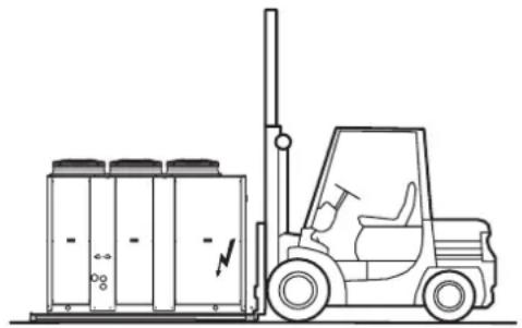
natural_image
Line drawing of a forklift carrying electrical equipment next to a storage cabinet (no text or symbols)Fig. 2Fig. 1

Fig. 5
Fig. 3


RECEPTION AND POSITIONING
- Handling and lifting with a crane or similar
Using the brackets (Part 1 Fig.4) located by the lifting holes (refer to the "DIMENSIONAL and PHYSICAL DATA" section).
- Consult the WEIGHTS AND CENTERS OF GRAVITY DURING TRASPORT AND OPERATION section for the center of gravity position.
NOTE: To correctly lift the machine, the belts used must be longer than 3.5 meters.
Refer to the data plates (Fig.5) that identify the center of gravity position, applied to the 4 sides of the base.
Use corner protectors (Part.2 Fig.4) to avoid damaging the unit.
Fig. 4

Make sure that the appliance is handled with care and without jolting as rough treatment could damage the functional parts of the unit.
WARNING:
To safeguard persons and property, read the information on the packing that covers the unit before handling. Also make sure to:
- Handle the unit with care
- Do not stack other objects on top of the unit
Storage
The units must be stored in a dry place, sheltered from the sun, rain, sand and wind.
Comply with the storage conditions given below:
- Do not stack the units
• Maximum temperature = 60°C
• Minimum temperature = -10°C
• Humidity = 90% - Avoid placing the units packaged with thermoretractable protection under the sun since the pressure inside the refrigerant circuits can increase up to values such as to open the safety valve.
Packing removing
Recycle and dispose of packing material in conformity with local regulations, be extremely careful not to damage the unit.
RECEPTION AND POSITIONING
Positioning
Before positioning please consider the overall dimensions and the technical requirements of the system and the unit, electric and hydraulic connections and any air pipes/ducts or free passages.
Neglecting these aspects may decrease performance and operational life of the unit and therefore increase the operating costs and maintenance.
Units are designed to be installed OUTSIDE and in fixed positions.
The unit is designed to be installed outside and in a fixed location and accessible only by qualified and authorized personnel.
Safety valve (if present): the installer is required to evaluate (according to EN378-2) the need and type of pipe to piped outlet in accordance with local regulations.
To prevent the transmission of vibrations evaluate the need for vibration dampers mounting
Before placing the unit be sure that:
- the location is in a safe accessible place
- the framework or the floor is adequate to support the weight of the unit WORKING (tank filled with water, etc...), please refer to weight paragraph
• support points are leveled and aligned
• the place can not be subject to flooding - the maximum level of the snow does not obstruct the airflow to the unit
To ensure the best air circulation to the unit and thus ensure a smooth operation it is recommended to:
- avoid obstructions to air flow near or above the unit
- protect the unit from high winds that can favor or not the airflow
- protect the unit from heat sources or pollutants (chimneys, extractors...)
- protect the unit from air stratification or recirculation (avoid ducting of the fans, containment structure, high walls or corners next to the unit)
These advises if not respected can lead to a lower efficiency of the unit or to high pressure stops (in summer) or low pressure stops (in winter).
HYDRAULIC CONNECTIONS
General rules
A mesh filter (hole < 1mm for plates heat exchanger < 1.5mm for shell and tubes heat exchanger) must be installed on the unit's water inlet otherwise warranty is immediately forfeited. The filter
The filter performs the function of blocking any foreign matter in the system's plumbing circuit (shavings, machining debris, etc.) limiting or avoiding possible problems of fouling (that decreases the heat exchange coefficient), erosion, and clogging. The clogging and fouling of the exchanger can lead to a reduction of the water flow rate and. In the case that the exchanger works as evaporator- of the evaporation temperature: these 2 factors can cause the icing of the exchanger
The icing event leads to the bursting of the exchanger, the inlet of water into the refrigerant circuit and so the necessity of a replacement of the main components (compressors, filters, expansion valves,. Etc.) and an accurate washing of components as refrigerant pipes, coils, etc., practically the rebuilding nearly complete of the refrigerant circuit.
The filter must be maintained clean: this is so necessary to verify the cleanness after the unit installation and checking periodically the state.
Protection devices
Standard supply includes a differential pressure switch situated between the water inlet and outlet of the heat exchanger to avoid freezing if the water flow stops for any reason.
Activation is calibrated for a 80 mbar ±5 Δp, while resetting occurs with a Δp of 105 mbar ±5.
The differential pressure switch opens the contact and shuts down the compressors when the water flow ratey decreases and Δp ≤ 80 mbar ± 5 .
The differential pressure switch closes and therefore the unit can restart when the water flow rate increases and Δp ≥ 105 mbar ± 5 .
- Standard supply includes an antifreeze heater placed between the external thermal insulation and the shell of the exchanger and controlled by the main electronic controller of the unit in order to protect the evaporator full of water (but not the pipes) from the winter icing when the unit is in stand-by mode. The exchanger is protected down to an outdoor air temperature of -20°C .
NOTE the antifreeze protection only work if the unit is electrically connected the standby period.
It is recommended to install a water paddle flow switch at the water inlet of the unit (it can be supplied as accessory or option): the water paddle flow switch has to be electrically wired in series with the differential pressure switch.
It is mandatory to calibrate the trip out of the water paddle flow switch at a water flow rate value higher than the minimum water flow rate admissible for the exchanger (re. section Pressure Drop).
Tips for a successful installation
For a correct design and installation of the hydraulic plant comply the local laws governing safety matters and sound...
The following information is suggestion for a correct installation of the unit:
- Before connecting the unit to the system wash adequately the pipes using clean water, filling and emptying and cleaning the filters. Only after that proceed connecting the unit to the system; this operation is crucial to ensure proper start-up without the need to have repeated stops to clean the filter, with the possible risk of damage to heat exchangers and other components.
- Check by qualified personnel the quality of the water or of the mixture used; avoid the presence of inorganic salts, biological load (seaweeds, etc.) suspended solids, dissolved oxygen and the pH. Water with inadequate characteristics can cause a pressure drop increase due to a rapid fouling of the filter, energy efficiency decrease and corrosive symptom increase that can damage the unit.
- The pipes must have the least possible number of bends to minimize load losses and must be adequately supported in order to prevent the connections of the unit from being excessively stressed.
- Install on-off valves near components that need to be serviced to isolate them when maintenance work needs to be done and to allow them to be replaced without having to discharge the system.
- Before isolating the pipes and charging the system, carry out preliminary inspections to make sure that there are no leaks.
- Isolate all the chilled water pipes to prevent condensation from forming along the pipes themselves. Make sure that the material used is the steam barrier type, failing this, cover the insulation with an appropriate protection. Also make sure that the air venting valves can be accessed through the insulation.
- Do not forget to install or at least allow for the installation of pressure and temperature reading instruments on the inlet and outlet parts of the hydraulic circuit. These instruments will allow you to monitor the operation of the system.
- The circuit can be kept under pressure by means of an expansion tank and a pressure reducer. A plant filling unit can also be used in order to automatically charge the system and keep it at the desired pressure if it drops below a certain pressure value. Install manual or automatic values in the highest point of the system to eliminate air from the circuit.
Fit manual or automatic valves at the highest point in the circuit in order to vent air from the circuit.
- the water connections are Victaulic-type joints for hooking up to the unit.
The joints allow the pipes to expand due to changes in temperature and in addition the elastomer gasket and the specified play help insulate and absorb noise and vibration.
- If vibrations dampers are installed under the unit, it is recommended to use flexible couplings before and after the water circulation pump and near the unit.
- Install on the outlet of the unit a suitable valve able to regulate the water flow.
- Avoid that the weight of the connection pipes pushes on the hydraulic connections of the unit using approved supports.
Check that plant components are suitable to bear the maximum static pressure (it depends on the height of the building).
HYDRAULIC CONNECTIONS
Water component for corrosion limit
| pH 7.5 ÷ 9.0 - | ||
| SO4 -- < 100 ppm | ||
| HCO3-/ SO4 -- >1.0 | ||
| Total hardness 8.0 ÷ 15.2 °F | ||
| Cl- < 50 ppm | ||
| PO4 3- < 2.0 ppm | ||
| NH3 < 0.5 ppm | ||
| Free Chlorine < 0 | 5 ppm | |
| Fe3+ < 0.5 ppm | ||
| Mn++ < 0.05 | ppm | |
| CO2 | < 50 ppm | |
| H2S | < 50 | ppb |
| Temperature | < 65 | °C |
| Oxygen content | < 0.1 ppm |
Precautions for the Winter
The water could freeze and damage the exchanger of the unit and other parts of the system during the winter period, if the system was to remain at a standstill. This problem can be obviated in 3 different ways:
- Drain the system completely, taking care to drain the plate exchanger (in order to drain the unit's piping system completely, open the water drain ball valves and the air vent valves, open any valves closed).
- Operate with glycol water taking account, depending on the % of glycol, of the factor of correction of the refrigerating capacity, power input, water flow rate and losses of head (see table on following page)
- If it is certain that the unit will always be powered throughout the winter, the unit is able to protect itself from freezing, down to a temperature of -20°C : this is possible thanks to an antifreeze electric heating element installed on the plate exchanger and intelligent control of the water pump that must be governed by the microprocessor board (see the “Electric Connections” section). If the unit is fitted with a Storage tank, solution no. 3 requires installing the tank antifreeze heating element accessor.
HYDRAULIC CONNECTIONS
Basic diagram Standard Unit VB [PLANT SIDE WATER CIRCUIT]
The following figures represent connections to the plant side exchanger.
IMPORTANT: There must be a constant flow of water to the exchanger. With accessory primary-secondary pumping module MP PS STD is mandatory to install a water filter in the secondary circuit immediately after of the water tank.
VB + hydronic kit accessory MP AM and MP SS
![FERROLI RGA - Basic diagram Standard Unit VB [PLANT SIDE WATER CIRCUIT] - 1](/content/2026/05/888532/images/12b0195bf1f28af2b71c07215ca6ef6945a2e8d9c6d05624c85731862f416414.jpg)
flowchart
graph LR
    IN["IN"] -->|IN| A["Component 1"]
    OUT["OUT"] -->|OUT| B["Component 2"]
    A --> C["Output"]
    B --> D["Component 3"]
    D --> E["Output"]
    style A fill:#f9f,stroke:#333
    style B fill:#f9f,stroke:#333
    style C fill:#ccf,stroke:#333
    style D fill:#ccf,stroke:#333
    style E fill:#cfc,stroke:#333
VB + hydronic kit accessory MP PS and only tank SAA
CHILLER
![FERROLI RGA - Basic diagram Standard Unit VB [PLANT SIDE WATER CIRCUIT] - 2](/content/2026/05/888532/images/c32a1a0bfe02df222bd7916157012b0e3f16e06aebb36c21b98eb21d92598975.jpg)
flowchart
graph LR
    A["HILLER"] --> B["IN"]
    A --> C["OUT"]
    B --> D["In"]
    C --> E["OUT"]
    D --> F["Valve 1"]
    D --> G["Valve 2"]
    D --> H["Valve 3"]
    E --> I["Valve 4"]
    E --> J["Valve 5"]
    E --> K["Valve 6"]
    F --> L["Valve 7"]
    G --> M["Valve 8"]
    H --> N["Valve 9"]
    I --> O["Valve 10"]
    J --> P["Valve 11"]
    K --> Q["Valve 12"]
    L --> R["Device 1"]
    M --> S["Device 2"]
    N --> T["Device 3"]
    O --> U["Device 4"]
    P --> V["Device 5"]
    Q --> W["Device 6"]
    R --> X["Device 7"]
    S --> Y["Device 8"]
    T --> Z["Device 9"]
    U --> AA["Device 10"]
Basic diagram for units with Recovery [RECOVERY WATER CIRCUIT]
The basic diagram given is valid for VD-VR version
The figure below shows the basic diagram of the portion of the system with the heat exchanger used for recovering partially heating power that would otherwise be disposed of in the air.
IMPORTANT: The water flow to the heat exchanger must be constant, it is required to install a water filter upstream of the exchanger.
![FERROLI RGA - Basic diagram Standard Unit VB [PLANT SIDE WATER CIRCUIT] - 3](/content/2026/05/888532/images/fc7c171f2b14d37bf38511eb0d88eb839fc7711210eb6c212471f2f2c950e699.jpg)
flowchart
graph LR
    IN["IN"] --> OUT["OUT"]
    OUT -->|IN| A["Valve 1"]
    A --> B["Valve 2"]
    B --> C["Valve 3"]
    C --> D["Valve 4"]
    D --> E["Valve 5"]
    E --> F["Valve 6"]
    F --> G["Valve 7"]
    G --> H["Valve 8"]
    H --> I["Recovery hot water tank"]
    I --> J["Valve 9"]
    J --> K["Valve 10"]
    K --> L["Valve 11"]
    L --> M["Valve 12"]
    M --> N["Valve 13"]
    N --> O["Valve 14"]
    O --> P["Valve 15"]
    P --> Q["Valve 16"]
    Q --> R["Valve 17"]
    R --> S["Valve 18"]
    S --> T["Valve 19"]
    T --> U["Valve 20"]
    U --> V["Valve 21"]
    V --> W["Valve 22"]
    W --> X["Valve 23"]
    X --> Y["Valve 24"]
    Y --> Z["Valve 25"]
(1): Component not required if the unit is equipped with the "Water storage tank" accessory. Installation of this accessory is recommended if the unit is without it.
I = User system

Pressure gauge

Thermometer

On-off and/or water flow rate regulating valve

Monitoring electronics (governor)

Pump

Filter

Tank

Expansion tank

Air vent valve

Safety valve

Coupling

Water filling unit

Three-way driven valve

Recovery water flow inlet probe
Air vent and water drain
On the plumbing circuit feeding the unit, especially when equipped with the standard pipe kit, the installer must fit an appropriate number of valves (manual or automatic) at the top of the circuit in order to vent any air in the plumbing system. In the same way, he must install a water drain valve in order, when necessary, to drain the unit's plate exchanger completely (especially during the winter in order to prevent freezing that would seriously jeopardize the operation of the unit). For units with the complete pipe kit there is an air vent valve on the top pipe (water inlet) and a water drain valve on the bottom pipe (water outlet). See “Accessories and options” section.
Piping connection with Victaulic couplings and Water flow switch
It is composed of two Victaulic type quick couplers (Fig. 1-A) comprehensive of union (Fig. 1-B) and seal not installed (supplied with the unit). The unions are supplied to be welded on the end. Here we give the instructions to follow for installing the quick couplers.
Do not weld the pipe with Victaulic connection joint attacked since the gasket may be damaged irreparably.
Note:
Supplied as optional (see "ACCESSORIES AND OPTIONAL EQUIPMENT").
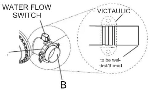
Valve regulating diagram valve
To prevent problems from occurring when the unit is started with very cold water, you are strongly advised to install a mixer valve as shown in the diagram.
The valve must be regulated to suit the temperature at which the water flows into the desuperheater (see diagram): the graph on the right shows the type of adjustment to use.
Water connections must be performed carefully as for the evaporator (filter, circuit washing, etc.)
Perform all necessary interventions to avoid RISK OF FREEZING (tubes insulation, emptying of circuit, addition of glycol, anti-freeze resistances).
Water temperature can reach high temperatures (up to 100°C for VD unit, up to 65°C for VR unit), therefore:
- avoid RISK OF BURNS by adopting the necessary precautions (insulations of tubes, temperature detecting station on water if the sanitary use is foreseen, etc.).
- install safety valves and specifically dimensioned expansion tanks in the hydraulic circuit.

line
| Recovery INLET temperature | QAB=100% | | :--- | :--- | | 30°C | QA | | 35°C | QB |HYDRAULIC CONNECTIONS
| ISO-G DN(mm) EXTERNAL DIAMETER OD(mm) A B O D T | ||||||||
| 1" 25 3 | 3.7 15.875 7 | 137 30.226 1.600 1.651 | ||||||
| 11/4" 32 | 42.4 15.875 | 7.137 38.989 1.600 1.651 | ||||||
| 11/2" 40 | 48.3 15.875 | 7.137 45.085 1.600 1.651 | ||||||
| 2" 50 6 | 0.3 15.875 8 | 738 57.150 1.600 1.651 | ||||||
| 21/2" 65 | 76.1 15.875 | 8.738 72.260 1.981 2.108 | ||||||
| 3" 80 8 | 8.9 15.875 8 | 738 84.938 1.981 2.108 | ||||||
| 4" 100 | 114.3 15.875 | 8.738 110.084 2.108 2.108 | ||||||
| 5" 125 | 139.7 | 15.875 8.738 135.500 2.134 2.769 | ||||||
| 6" 150 | 168.3 | 15.875 8.738 163.957 2.159 2.769 | ||||||
| 8" | 200 | 219.1 | 19.050 | 11.913 | 214.401 | 2.337 | 2.769 | |
1) Pipe groove inspections
Check the depth and diameter of the grooves and their distance from the pipe ends. Make sure that the work has been carried out with care and that the end surface of the pipes is smooth and not ovalized. Make sure that there are no notches, burrs or other imperfections that could impair the tightness. Groove dimensions in mm A=16-B=8-C=57.2-D=1.6

2) Checking the seal and relative lubrication
Make sure that the type of seal used is compatible with the nature and temperature of the fluid. Signal green EPDM seals are used.
Apply a film of grease to the seal: on the back, on the side flanks and on the inner lips that contact the pipe. Work in conditions of the utmost cleanliness as particles of dirt could damage the seal. Always and only use synthetic grease. Greasing makes it easier to fit the seal on the pipe and improves the tightness. It also allows the seal to slide within the connection, avoiding tensions and projections near the bolts.
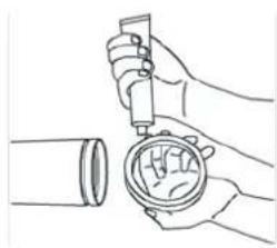
natural_image
Line drawing of hands using a tool to adjust or install a mechanical component (no text or symbols present)3) How to fit the seal
Fully insert the seal into the end of a pipe. Make sure that the seal lips adhere to the pipe itself.

natural_image
Line drawing of a hand holding a cylindrical object (no text or symbols)4) Alignment
Align the pipes and move their ends near to each other. Now push the seal, centering it on the two pipe ends. The seal must remain inside the grooves.
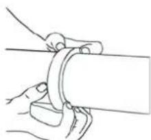
natural_image
Line drawing of hands fastening a cylindrical pipe joint (no text or symbols)5) Joint assembly
Remove one bolt and loosen (without removing) the other one. Seat part of the body of the joint at the bottom, between the pipe ends, inserting and edges of the grooves. Now seat the other part of the body at the top, on the two ends, and close the joint. Make sure that the parts of the body of the joint touch each other.

natural_image
Line drawing of hands performing a manual task on a mechanical clamp (no text or symbols)6) Nut torquing
Fit the previously removed bolt back in place and tighten both nuts by hand. Now torque them with the relative wrench, tightening them alternately a few turns.

natural_image
Line drawing of a hand using a tool to lift a mechanical component (no text or symbols)WARNING:
If one nut is fully tightened at a time, the seal could slip between the jaws of the opposite side of the joint.
MAXIMUM VOLUME OF WATER
Maximum volume of water in the system with wet module
Before filling the water system, it is advisable to consider the type of installation in question, i.e. check the difference in level between the wet module and user. The following table gives the maximum water content of the water supply system in liters, depending on the capacity of the standard expansion vessel supplied and the pressure at which it should be charged. The expansion vessel setting must be regulated to suit the maximum positive difference in level of the user.
Maximum setting value 600 kPa.
With a positive H of more than 12.25 meters, calculate the expansion vessel precharge value in kPa using the formula below:
Expansion vessel precharge= [H/10.2+0.3]×100=[kPa]
NOTE. In case A, make sure that the user's lowest point is able to withstand the global pressure.
Tab.1
| Model 40-50-60-70-80 90-100-110-115-130-145-160-180-200 | ||||||
| Expansion vessel volume (liters) 12 24 | ||||||
| Thermal expansion of water (10-40°C) 0.0074 | ||||||
| Thermal expansion of water (10-60°C) 0.0167 | ||||||
| H (metri) | Expansion vessel pressure (kPa) | IR | IP | IR | IP | |
| Case A | H <0 | 150 (standard) | 1043 | 461 | 2085 | 921 |
| Case B | 0 < H < 12.25 | 150 (standard) | 1043 | 461 | 2085 | 921 |
| 15 177 980 435 | 1960 | 870 | ||||
| 20 226 866 384 | 1732 | 768 | ||||
| 25 275 753 334 | 1505 | 667 | ||||
| 30 324 640 283 | 1279 | 566 | ||||
NOTE: If the unit operates with brine, calculate the real volume of the system by taking into account the corrective factors for the volume of the system given in the table below.
Corrective factors per total maximum volume of the system with brine
| % of brine 0% 10% 20% 30% 40% | ||||
| Cooling Mode 1,000 0,738 0,693 0,652 0,615 | ||||
| Heating Mode 1,000 0,855 0,811 0,769 0,731 |

ELECTRICAL CONNECTIONS
General rules
The appliance must be wired in compliance with the laws in force in the country in which it is installed. The units are supplied fully wired in the factory and pre-engineered for connection to the electricity main. The electric panel is made in compliance with the technical standards in force in the European Union.
Structure of the electric panel
All the electrical components are contained in a closed casing protected against the atmospheric agents and inspectionable by opening the front door after removing the front panel. The door for accessing the power section is locked by the mechanism. Access for the supply cables and earth cable (PE) is permitted through the opening on the bottom of the electric panel.
Composition of the system
The system comprises an electromechanical part consisting of the power circuit, with disconnecting device, contactors, fuses or thermal cutouts, transformer, and another part comprising the Microprocessor control system.
NOTES: REFER TO THE WIRING DIAGRAM SUPPLIED WITH THE UNIT FOR THE LAYOUT OF THE ELECTRIC PANEL.
Electrical connections
All electrical connections must be carried out by qualified personnel in the absence of electric power. The table below gives the electrical specifications of the different constructional configurations of the units.
Unit
| UNIT | 40.2 | 50.2 | 60.2 | 70.2 | 80.2 | 90.2 | 100.2 | 115.2 | 130.2 | 145.2 | 160.2 | 180.2 | 200.2 | UM |
| Power supply | 400 - 3+N - 50 | 400 - 3 - 50 | V-ph-Hz | |||||||||||
| FLA | 40,2 | 45,7 | 53,3 | 58,7 | 69,6 | 75,5 | 90,0 | 97,9 | 106 | 123 | 136 | 159 | 170 | A |
| FLI | 21,6 | 24,4 | 28,4 | 31,0 | 36,2 | 44,0 | 55,0 | 60,5 | 66,0 | 75,7 | 83,3 | 95,4 | 103 | kW |
| MIC | 134 | 143 | 149 | 173 | 213 | 264 | 259 | 267 | 267 | 348 | 361 | 355 | 391 | A |
| MIC SS | 89,3 | 96,3 | 101 | 117 | 143 | 174 | 175 | 183 | 183 | 200 | 246 | 248 | 272 | A |
Unit layout

Compressors
| UNIT | 40.250 | 260.27 | 0.280.2 | 90.2100 | 2115.2 | 130.214 | 5.2160 | 2180.22 | 00.2 | UM | |||||
| Power supply 400 - 3 - 50 V-ph-Hz | |||||||||||||||
| FLA | CP1A 2 | 1,0 22,0 | 25,0 31,0 | 34,0 40 | 0 44,0 5 | 3,0 53,0 | 66,0 66,0 | 76,0 81 | 0 | A | |||||
| CP1B 2 | 1,0 22,0 | 25,0 31,0 | 34,0 34 | 0 44,0 4 | 4,0 53,0 | 53,0 66,0 | 76,0 81 | 0 | |||||||
| LRA | CP1A | 111 | 118 | 118 | 140 | 174 | 225 | 210 | 210 | 210 | 287 | 287 | 267 | 298 | A |
| CP1B | 111 | 118 | 118 | 140 | 174 | 174 | 210 | 210 | 210 | 210 | 287 | 267 | 298 | ||
| FLI | CP1A 1 | 0,2 | 1,6 13,3 | 14,6 17,2 | 22,6 25 | 4 30,9 3 | 0,9 38,5 | 38,5 43,5 | 47,1 | kW | |||||
| CP1B | 10,2 | 11,6 | 13,3 | 14,6 | 17,2 | 17,2 | 25,4 | 25,4 | 30,9 | 30,9 | 38,5 | 43,5 | 47,4 | ||
| Winding resistance | CP1A 1 | 40 1,20 | 1,20 1,10 | 0,80 0,60 | 0,60 0 | 50 0,50 | 0,30 0,30 | 0,30 0,30 | Ω | ||||||
| CP1B 1 | 40 1,20 | 1,20 1,10 | 0,80 0,80 | 0,60 0 | 60 0,50 | 0,50 0,30 | 0,30 0,30 | ||||||||
NOTE:
FLA = Full load current at maximum tolerated conditions
LRA = Locked rotor current
FLI = Full load power input at maximum tolerated conditions
MIC = Maximum instantaneous current of the unit
MIC SS = Maximum instantaneous current of the unit with soft starter options
ELECTRICAL CONNECTIONS
Single Fan AC specifications
| UNIT | 40.2 | 50.2 | 60.2 | 70.2 | 80.2 | 90.2 | 100.2 | 115.2 | 130.2 | 145.2 | 160.2 | 180.2 | 200.2 | UM |
| Power supply | 230 - 1 - 50 | 400 - 3 - 50 | V-ph-Hz | |||||||||||
| FLA | 2,62 | 4,10 | A | |||||||||||
| LRA | 10,5 | 13,5 | A | |||||||||||
| FLI | 0,60 | 2,10 | kW | |||||||||||
Single Fan EC specifications
| UNIT | 40.2 | 50.2 | 60.2 | 70.2 | 80.2 | 90.2 | 100.2 | 115.2 | 130.2 | 145.2 | 160.2 | 180.2 | 200.2 | UM |
| Power supply | 230 - 1 - 50 | 400 - 3 - 50 | V-ph-Hz | |||||||||||
| FLA | 3,20 | 2,85 | A | |||||||||||
| LRA | 12,8 | 11,4 | A | |||||||||||
| FLI | 0,72 | 1,85 | kW | |||||||||||
Summary Fan AC specifications
| UNIT | 40.2 | 50.2 | 60.2 | 70.2 | 80.2 | 90.2 | 100.2 | 115.2 | 130.2 | 145.2 | 160.2 | 180.2 | 200.2 | UM |
| Power supply | 230 - 1 - 50 | 400 - 3 - 50 | V-ph-Hz | |||||||||||
| FLA | 5,24 | 7,86 | 8,20 | 12,3 | 16,4 | A | ||||||||
| LRA | 21,0 | 31,4 | 27,0 | 40,5 | 54,0 | A | ||||||||
| FLI | 1,20 | 1,80 | 4,20 | 6,30 | 8,40 | kW | ||||||||
Summary Fan EC specifications
| UNIT | 40.2 | 50.2 | 60.2 | 70.2 | 80.2 | 90.2 | 100.2 | 115.2 | 130.2 | 145.2 | 160.2 | 180.2 | 200.2 | UM |
| Power supply | 230 - 1 - 50 | 400 - 3 - 50 | V-ph-Hz | |||||||||||
| FLA | 6,40 | 9,60 | 5,70 | 8,55 | 11,4 | A | ||||||||
| LRA | 25,6 | 38,4 | 22,8 | 34,2 | 45,6 | A | ||||||||
| FLI | 1,44 | 2,16 | 3,70 | 5,55 | 7,40 | kW | ||||||||
Primary-secondary pump
| UNIT | 40.250.260.270.280.290.2100.2115.2130.2145.2160.2180.2200.2 | UM | |||||||||||
| Power supply 400 - 3 - 50 | V-ph-Hz | ||||||||||||
| FLA | 3,20 3,20 3,20 3,20 3,20 | 3,70 3,70 3,70 3,70 3,70 4,50 4,50 6,10 | 6,10 | A | |||||||||
| LRA | 25,7 25,7 25,7 25,7 25,7 | 20,0 20,0 20,0 20,0 43,5 43,5 57,7 | 57,7 | A | |||||||||
| FLI | 1,80 1,80 1,80 1,80 1,80 | 1,78 1,78 1,78 1,78 2,55 2,55 3,48 | 3,48 | kW | |||||||||
Standard pump
| UNIT | 40.250 | 260.270 | 280.290 | 2100 | 2115.2130 | 2145 | 2160 | 2180 | 2200.2 | UM | |||||
| Power supply 400 - 3 - 50 | V-ph-Hz | ||||||||||||||
| FLA | 3,70 | 3,70 | 3,70 | 3,70 | 4,50 | 4,50 | 4,50 | 4,50 | 6,10 | 6,10 | 8,70 | 8,70 | A | ||
| LRA | 20,0 | 20,0 | 20,0 | 20,0 | 43,5 | 43,5 | 43,5 | 43,5 | 57,7 | 57,7 | 87,0 | 87,0 | A | ||
| FLI | 1,78 | 1,78 | 1,78 | 1,78 | 2,55 | 2,55 | 2,55 | 2,55 | 3,48 | 3,48 | 4,56 | 4,56 | kW | ||
High head pump
| UNIT | 40.250.260.270.280.290.2100.2115.2130.2145.2160.2180.2200.2 | UM | ||||||||||||
| Power supply 400 - 3 - 50 | V-ph-Hz | |||||||||||||
| FLA | 6,10 6,10 6,10 6,10 6,10 6,10 6,10 6,10 6,10 6,10 6,10 6,10 6,10 6,10 6,10 6,10 6,10 6,10 6,10 6,10 6,10 | A | ||||||||||||
| LRA | 57,7 57,7 57,7 57,7 57,7 57,7 57,7 57,7 57,7 57,7 57,7 57,7 57,7 57,7 57,7 57,7 57,7 57,7 57,7 57,7 57,7 | A | ||||||||||||
| FLI | 3,48 3,48 3,48 3,48 3,48 3,48 3,48 3,48 3,48 3,48 3,48 3,48 3,48 3,48 3,48 3,48 3,48 3,48 3,48 3,48 3,48 | kW | ||||||||||||
Standard modulating pump
| UNIT | 40.2 | 50.2 | 60.2 | 70.2 | 80.2 | 90.2 | 100.2 | 115.2 | 130.2 | 145.2 | 160.2 | 180.2 | 200.2 | UM |
| Power supply 400 - 3 - 50 | V-ph-Hz | |||||||||||||
| FLA | 3,70 3,70 | 3,70 3,70 | 3,70 3,70 | 4,50 4,50 | 4,50 4,50 | 4,50 4,50 | 6,10 6,10 | 8,70 | A | |||||
| LRA | 20,0 20,0 | 20,0 20,0 | 20,0 20,0 | 43,5 43,5 | 43,5 43,5 | 43,5 43,5 | 57,7 57,7 | 87,0 | A | |||||
| FLI | 1,78 1,78 | 1,78 1,78 | 1,78 1,78 | 2,55 2,55 | 2,55 2,55 | 2,55 2,55 | 3,48 3,48 | 4,56 | kW | |||||
High head modulating pump
| UNIT | 40.2 | 50.2 | 60.2 | 70.2 | 80.2 | 90.2 | 100.2 | 115.2 | 130.2 | 145.2 | 160.2 | 180.2 | 200.2 | UM |
| Power supply 400 - 3 - 50 | V-ph-Hz | |||||||||||||
| FLA | 6,10 6, | 10 6,10 | 6,10 6,10 | 6,10 6,1 | 0 8,70 8, | 70 8,70 | 8,70 10,4 | 10,4 | A | |||||
| LRA | 57,7 57 | 7,7 57,7 | 57,7 57,7 | 57,7 57,7 | 87,0 87 | 0 87,0 | 87,0 116 | 116 | A | |||||
| FLI | 3,48 3, | 48 3,48 | 3,48 3,48 | 3,48 3,48 | 4,56 4, | 56 4,56 | 4,56 6,29 | 6,29 | kW | |||||
NOTE:
FLA = Full load current at maximum tolerated conditions
LRA = Locked rotor current
FLI = Full load power input at maximum tolerated conditions
MIC = Maximum instantaneous current of the unit
MIC SS = Maximum instantaneous current of the unit with soft starter options
ELECTRICAL CONNECTIONS
Summary tables (total values):
Units with primary-secondary pump
| UNIT | 40.250 | 260.270 | 280.290 | 2100 | 2115 | 2130.214 | 2160 | 2180 | 2200.2 | UM | ||||
| Power supply | 400 - 3+N - 50 400 - 3 - 50 | V-ph-Hz | ||||||||||||
| FLA | 43,4 | 48,9 | 56,5 | 61,9 | 72,8 | 79,2 | 93 | 102 | 110 | 128 | 141 | 165 | 176 | |
| FLI | 23,4 | 26,2 | 30,2 | 32,8 | 38,0 | 45,8 | 56 | 62,3 | 67,8 | 78,3 | 85,9 | 98,9 | 106 | |
| MIC | 137 | 147 | 152 | 176 | 216 | 268 | 263 | 271 | 271 | 353 | 366 | 361 | 397 | A |
| MIC SS | 92,5 | 99,5 | 105 | 120 | 146 | 178 | 179 | 187 | 187 | 205 | 251 | 254 | 278 | A |
Standard unit
| UNIT | 40.250 | 260.270 | 280.290 | 2100 | 2115 | 2130.21 | 45.2160 | 2180.2200.2 | UM | ||||||
| Power supply | 400 - 3+N - 50 400 - 3 - 50 | V-ph-Hz | |||||||||||||
| FLA | 43,9 | 49,4 | 57,0 | 62,4 | 73,3 | 80,0 | 94 | 102 | 110 | 129 | 142 | 168 | 179 | ||
| FLI | 23,4 | 26,2 | 30,2 | 32,8 | 38,0 | 46,6 | 57 | 663,1 | 68,6 | 79,2 | 86,8 | 100 | 107 | ||
| MIC | 137 | 147 | 152 | 177 | 216 | 269 | 264 | 272 | 272 | 354 | 367 | 363 | 400 | A | |
| MIC SS | 93,0 | 100 | 105 | 121 | 147 | 179 | 180 | 188 | 188 | 206 | 253 | 257 | 281 | A | |
Units with high head pump
| UNIT | 40.250 | 260.270 | 280.290 | 2100 | 2115 | 2130.214 | 45.2160 | 2180.2200.2 | UM | ||||
| Power supply | 400 - 3+N - 50 400 - 3 - 50 | V-ph-Hz | |||||||||||
| FLA | 46,3 51 | 8 59,4 | 64,8 75,7 | 81,6 96 | 1 107 1 | 15 132 1 | 45 169 | 180 | A | ||||
| FLI | 25,1 27 | 9 31,9 | 34,5 39,7 | 47,5 58 | 5 65,1 7 | 0,6 80,3 | 87,9 102 | 109 | kW | ||||
| MIC | 140 | 150 | 155 | 179 | 219 | 270 | 265 | 276 | 276 | 357 | 370 | 365 | 402 |
| MIC SS | 95,4 | 102 | 107 | 123 | 149 | 180 | 181 | 192 | 192 | 209 | 255 | 258 | 282 |
Units with standard modulating pump
| UNIT | 40.250 | 260.270 | 280.290 | 2100 | 2115 | 2130.214 | 45.2160 | 2180.2200.2 | UM | ||||
| Power supply | 400 - 3+N - 50 400 - 3 - 50 | V-ph-Hz | |||||||||||
| FLA | 43,9 | 49,4 | 57,0 | 62,4 | 73,3 | 80,0 | 94,5 | 102 | 110 | 129 | 142 | 168 | 179 |
| FLI | 23,4 | 26,2 | 30,2 | 32,8 | 38,0 | 46,6 | 57,6 | 63,1 | 68,6 | 79,2 | 86,8 | 100 | 107 |
| MIC | 137 | 147 | 152 | 177 | 216 | 269 | 264 | 272 | 272 | 354 | 367 | 363 | 400 |
| MIC SS | 93,0 | 100 | 105 | 121 | 147 | 179 | 180 | 188 | 188 | 206 | 253 | 257 | 281 |
Units with high head modulating pump
| UNIT | 40.250 | 260.270 | 280.290 | 2100 | 2115 | 2130.214 | 2160 | 2180 | 2200.2 | UM | ||||
| Power supply | 400 - 3+N - 50 400 - 3 - 50 | V-ph-Hz | ||||||||||||
| FLA | 46,3 51 | 8 59,4 | 64,8 75,7 | 81,6 96 | 1 107 1 | 15 132 1 | 45 169 | 180 | A | |||||
| FLI | 25,1 27 | 9 31,9 | 34,5 39,7 | 47,5 58 | 5 65,1 7 | 0,6 80,3 | 87,9 102 | 109 | kW | |||||
| MIC | 140 | 150 | 155 | 179 | 219 | 270 | 265 | 276 | 276 | 357 | 370 | 365 | 402 | A |
| MIC SS | 95,4 | 102 | 107 | 123 | 149 | 180 | 181 | 192 | 192 | 209 | 255 | 258 | 282 | A |
NOTE:
FLA = Full load current at maximum tolerated conditions
LRA = Locked rotor current
FLI = Full load power input at maximum tolerated conditions
MIC = Maximum instantaneous current of the unit
MIC SS = Maximum instantaneous current of the unit with soft starter options
ELECTRICAL CONNECTIONS
1) Connection to the electricity main
- Power supply line;
The unit's power supply line must be laid by following a clearly defined route in order to make it as correct as possible any without any breaks. Pass the line through the opening on the button of the electrical panel. Secure the line integral with the structure of the unit. Then continue inside the panel and connect the conductors directly to the input terminals of the main disconnecting device of the unit. The characteristics of the main lines should be determined by qualified personnel specialized in the design of electrical systems, according to your national regulations and standards.
• Power supply system;
The power cables of the unit's supply line must be taken from a system of symmetrical three-phase voltages (difference between voltage max 2%) and of a separate protection conductor.
V = 3 8 0 ÷ 4 1 5 V
f = 5 0 Hz
• Protection on supply side:
An automatic switch must be installed on the supply side of the side in order to protect against any overcurrents and indirect contacts that could occur when the unit is operating.
It is advisable to install an automatic current limiter switch in order to limit the effective short-circuit current in the connecting point of the unit. This allows a protection device with a lower breaking capacity than that required in the connection point to be sized like the main circuit-breaker of the unit.
The line and switch must be coordinated in compliance with the current laws governing electrical safety matters, regarding the type of installation and environmental conditions in which the unit must operate.
- Protection conductor (ground wire):
The protection conductor from the feeder line must be connected straight to the ground screw identified by code “PE”, which ensures the equipotential connection of all metal grounding points and structural parts of the unit.
• Signals and data lines
Do not exceed the maximum allowed distance of the cable as shown in the wiring diagram. Put cables away from power lines with a different voltage or emitting electromagnetic noise, if really necessary do not to put in parallel but only cross with these cables to 90° . Do not put cables near equipment that can create electromagnetic interference (antennas, speakers, radio repeaters etc ...). Any shielding of the cable must be connected to a ground without noise, while preserving the continuity across the total length of the cable.
- Connection
Always refer to the wiring diagram supplied with the unit. Verify that the network has characteristics corresponding to the data shown on the nameplate of the unit. Before starting work, verify that the switching device at the start of the line power unit is open, locked and a warning sign shown. Make the connection to the ground first that the others phase; protect the wires using cable properly fitted. Before powering on the unit, ensure that you have restored all the protections that were removed during work on connection.
2) Electric panel
- Protection degree:
The electric panel casing is made from sheet metal and has IP54 protection rating at the doors directly accessible from the outside. The other parts of the casing guarantee a protection degree that is at least equivalent to IP22, as established by the current laws in force: this has been achieved since the panel has further protection against the penetration of solid foreign bodies and atmospheric agents thanks to the unit structure in which it is housed.
- Starting and stopping function:
The red handle on the panel door directly acts on the main circuit-breaker. The handle also acts as a door lock since it ensures that the unit is only powered when the door is shut. The stopping function carried out by the main circuit-breaker is classified as type "0" since the unit is stopped by immediately cutting off the power supply.
3) Reference standards
• The provisions established by the following Directives have been complied with to ensure the safety of the electrical products placed on the European Union market:
- Low Voltage Directive 2006/95 EEC which also includes the following harmonized standards:
CEI EN 60335-1 and 60335-2-40.
Classification: CEI EN 60204-1. Safety of unitry. Electrical equipment of units. Part 1: General rules.
- Directive 2004/108/EEC concerning "Electromagnetic compatibility".
4) User connection
Inside the electrical panel is available a user terminal where you can have:
a) pumps start-up and safety devices
b) two user configurable inputs
c) digital Input for water paddle flow switch
d) integrative resistance output relay
e) clean contact for general alarm
f) external signal from the compressors running
Moreover, VR units contains the following terminals:
g) pumps start-up and safety devices
h) digital input for remote enable
i) digital Input for water paddle flow switch
For more details refer to the wiring diagram of the unit.
R410A PROTECTION DEVICES
Protection devices HIGH PRESSURE
The unit is protected against risk of overpressure by means of 4 levels protection chain.
Each circuit is equipped with:
1) ATC (Advanced Temperature Control) if present
2) high pressure automatic switch connected to electronic controller
3) high pressure manual switch connected to compressor contactor command
4) high pressure safety valve
Protection devices technical data
| LEVEL | 1 2 3 4 | |||
| Device | ATC(Advanced Temperature Control) if present | High pressure automatic switch | High pressure manual switch | High pressure safety valve |
| Trip out (barg) | - 41.0 43.0 45.0 | |||
| Trip in (barg) | - 29.5 31.0 41.0 | |||
| connected to | electronic controller electronic controller compressor contactor command | Discharge the refrigerant to atmosphere to reduce the system pressure | ||
| effect | Controls the cooling capacity shutting down compressors | stop the compressors and the fans of that circuit | stop the compressors of that circuit | Discharge the refrigerant to atmosphere to reduce the system pressure |
| reset * | Automatic | YES by keyboard if the high pressure switch has trip-in and after the solution of the problem that generates the alarm | Press the button present on the manual pressure switchCAUTION | Not necessary |
*: For more details refers to section monitoring basic system.
CAUTION
IN CASE OF COMPRESSORS TRIP-OUT BY MANUAL RESET HIGH PRESSURE SWITCH THERE ARE NO EVIDENCES IN THE MONITORING SYSTEM, DO NOT RESET THE PRESSURE SWITCH BEFORE YOU HAVE DONE THE FOLLOWING STEPS:
1) SHUT DOWN THE UNIT USING THE OFF BUTTON
2) THEN RESET THE HIGH PRESSURE SWITCH
Protection devices LOW PRESSURE
| LEVEL 1 2 | ||
| Device | Low pressure transducer | Low pressure automatic switch |
| Trip out (barg) | 2 bar 2 bar | |
| Trip in (barg) | 4 bar 4 bar | |
| connected to | electronic controller electronic controller | |
| effect | stop the compressors of that circuit | stop the compressors of that circuit |
| reset * | YES by keyboard after the solution of the problem that generates the alarm | YES by keyboard if the low pressure switch has trip-in and after the solution of the problem that generates the alarm |
Protection devices DISCHARGE TEMPERATURE (if installed)
| LEVEL 2 | |
| Device | Discharge Temperature |
| Trip out | 135°C |
| Trip in | 120°C |
| connected to | electronic controller |
| effect | stop the single compressor |
| reset * | YES by keyboard after the solution of the problem that generates the alarm |
*: For more details refers to section monitoring basic system.
Refrigerant flow diagram IR VB unit with thermostatic expansion valve
| Description | |
| B | EXPANSION VALVE BULB |
| BA | FIN AND TUBE COIL |
| C | EXPANSION VALVE CAPILLARY |
| CP | COMPRESSOR |
| FD | FILTER DRIER |
| IDL | LIQUID AND MOISTURE INDICATOR |
| MAP | HIGH PRESSURE GAUGE |
| MBP | LOW PRESSURE GAUGE |
| PAA | AUTO RESET HIGH PRESSURE SWITCH |
| PAA ATC | AUTO RESET HIGH PRESSURE SWITCH FOR ATC FUNCTION |
| PAM | MANUAL RESET HIGH PRESSURE SWITCH |
| PB | AUTO RESET LOW PRESSURE SWITCH |
| PDW | WATER PRESSURE SWITCH |
| PP | PRESSURE SOCKET 1/4" SAE WITOUT CORE |
| PPS | PRESSURE SOCKET 1/4" SAE WITH CORE |
| PPSS | PRESSURE SOCKET 5/16" SAE WITH CORE |
| RL | LIQUID BALL VALVE |
| RM | COMPRESSOR OUTLET BALL VALVE |
| SIW | WATER INLET PROBE |
| SL | LIQUID PROBE |
| SP | PLATE HEAT EXCHANGER |
| SUW | WATER OUTLET PROBE |
| TC | CHARGING TUBE |
| V | FAN |
| VSF | SAFETY VALVE |
| VT | EXPANSION VALVE |

flowchart
graph TD
    BA["BA"] --> RM*
    RM* --> TC
    TC --> PPSS
    PPSS --> IAP*
    IAP* --> PPS
    PPS --> VSF
    VSF --> PP
    PP --> PAM
    PAM --> CP1A
    CP1A --> TC
    TC --> PPSS
    PPSS --> PP
    PP --> PPS
    PPS --> PB
    PB --> MBP*
    MBP* --> PPS
    PPS --> PP
    PP --> C
    C --> OUT
    OUT --> SP
    SP --> IN
    IN --> SUW
    IN --> SIW
    IN --> PDW
    IN --> SW
    IN --> SIW
    LP*
    RL*
    RL* --> PPS
    PPS --> TC
    TC --> FD
    FD --> IDL
    IDL --> PPSS
    PPSS --> C
    C --> PP
    PP --> VT
    VT --> PPS
    style TA fill:#f9f,stroke:#333,stroke-width:2px
    note right of TA: * : Optional; line below TA: Insulated pipes for BR unit
Refrigerant flow diagram IR VB unit with thermostatic expansion valve
| Description | |
| BA | FIN AND TUBE COIL |
| CP | COMPRESSOR |
| EEV | ELECTRONIC EXPANSION VALVE |
| FD | FILTER DRIER |
| IDL | LIQUID AND MOISTURE INDICATOR |
| MAP | HIGH PRESSURE GAUGE |
| MBP | LOW PRESSURE GAUGE |
| PAA | AUTO RESET HIGH PRESSURE SWITCH |
| PAAATC | AUTO RESET HIGH PRESSURE SWITCH ATC FUNCTION |
| PAM | MANUAL RESET HIGH PRESSURE SWITCH |
| PB | AUTO RESET LOW PRESSURE SWITCH |
| PDW | WATER PRESSURE SWITCH |
| PP | PRESSURE SOCKET 1/4" SAE WITOUT CORE |
| PPS | PRESSURE SOCKET 1/4" SAE WITH CORE |
| PPSS | PRESSURE SOCKET 5/16" SAE WITH CORE |
| RL | LIQUID BALL VALVE |
| RM | COMPRESSOR OUTLET BALL VALVE |
| SIW | WATER INLET PROBE |
| SL | LIQUID PROBE |
| SP | PLATE HEAT EXCHANGER |
| SA | SUCTION PROBE |
| SUW | WATER OUTLET PROBE |
| TC | CHARGING TUBE |
| TP | PRESSURE TRANSDUCER |
| V | FAN |
| VSF | SAFETY VALVE |

flowchart
graph TD
    BA["BA"] --> RM*
    RM* --> TC
    TC --> PPSS
    PPSS --> PPS
    PPS --> PAA
    PAA --> ATC*
    VAP* --> PPS
    PPS --> VSF
    VSF --> PP
    PP --> PAM
    PAM --> PP
    PP --> PAA
    RCL* --> PPS
    RCL* --> TL
    TL --> TC
    TL --> FD
    FD --> IDL
    IDL --> PPSS
    PPSS --> CP1A
    CP1A --> CP1B
    CP1B --> TC
    TC --> PPSS
    PPSS --> PPS
    PPS --> PP
    PP --> PPS
    PPS --> OUT
    OUT --> SP
    SP --> IN
    SP --> EDV
    EDV --> IN
    IN --> SUW
    IN --> PDW
    IN --> SIW
    PPSS --> PPSS
    PPSS --> PP
    PPSS --> PPS
    PPSS --> MBP*
    MBP* --> PB
    MBP* --> MBP*
    LP1A --> CP1A
    CP1B --> CP1A
    LP2A --> CP1B
    LP3A --> CP1B
* : Optional
____:insulated pipes for BR unit
Refrigerant flow diagram IP VB unit with electronic expansion valve
| Description | |
| BA | FIN AND TUBE COIL |
| CP | COMPRESSOR |
| EEV | ELECTRONIC EXPANSION VALVE |
| FD | FILTER DRIER |
| IDL | LIQUID AND MOISTURE INDICATOR |
| MAP | HIGH PRESSURE GAUGE |
| MBP | LOW PRESSURE GAUGE |
| PAA | AUTO RESET HIGH PRESSURE SWITCH |
| PAAATC | AUTO RESET HIGH PRESSURE SWITCH FOR ATC FUNCTION |
| PAM | MANUAL RESET HIGH PRESSURE SWITCH |
| PB | AUTO RESET LOW PRESSURE SWITCH |
| PBE | EVAPORATOR AUTO RESET LOW PRESSURE SWITCH |
| PDW | WATER PRESSURE SWITCH |
| PP | PRESSURE SOCKET 1/4" SAE WITHOUT CORE |
| PPS | PRESSURE SOCKET 1/4" SAE WITH CORE |
| PPSS | PRESSURE SOCKET 5/16" SAE WITH CORE |
| RL | LIQUID BALL VALVE |
| RM | COMPRESSOR OUTLET BALL VALVE |
| SC | LIQUID RECEIVER |
| SEP | LIQUID SEPARATOR |
| SIW | WATER INLET PROBE |
| SL | LIQUID PROBE |
| SP | PLATE HEAT EXCHANGER |
| SA | SUCTION PROBE |
| SUW | WATER OUTLET PROBE |
| TC | CHARGING TUBE |
| TP | PRESSURE TRANSDUCER |
| V | FAN |
| VIC | REVERSING CYCLE VALVE |
| VSF | SAFETY VALVE |
| VU | CHECK VALVE |

flowchart
graph TD
    A["PPS"] --> B["TC"]
    B --> C["BA"]
    C --> D["OUT"]
    D --> E["IN"]
    E --> F["RL*"]
    F --> G["SL"]
    G --> H["PPS"]
    H --> I["RL*"]
    I --> J["PPSS"]
    J --> K["IDL"]
    K --> L["EEV"]
    L --> M["VU"]
    M --> N["PPSS"]
    N --> O["VU"]
    O --> P["DC"]
    P --> Q["SC"]
    Q --> R["PPS"]
    R --> S["PPSS"]
    S --> T["PPSS"]
    T --> U["PPSS"]
    U --> V["PPSS"]
    V --> W["PPSS"]
    W --> X["PPSS"]
    X --> Y["PPSS"]
    Y --> Z["PPSS"]
    Z --> AA["PPSS"]
    AA --> AB["PPSS"]
    AB --> AC["PPSS"]
    AC --> AD["PPSS"]
    AD --> AE["PPSS"]
    AE --> AF["PPSS"]
    AF --> AG["PPSS"]
    AG --> AH["PPSS"]
    AH --> AI["PPSS"]
    AI --> AJ["PPSS"]
    AJ --> AK["PPSS"]
    AK --> AL["PPSS"]
    AL --> AM["PPSS"]
    AM --> AN["PPSS"]
    AN --> AO["PPSS"]
    AO --> AP["PPSS"]
    AP --> AQ["PPSS"]
    AQ --> AR["PPSS"]
    AR --> AS["PPSS"]
    AS --> AT["PPSS"]
    AT --> AU["PPSS"]
    AU --> AV["PPSS"]
    AV --> AW["PPSS"]
    AW --> AX["PPSS"]
    AX --> AY["PPSS"]
    AY --> AZ["PPSS"]
    AZ --> BA["PPSS"]
    BA --> BB["PPSS"]
    BB --> BC["PPSS"]
    BC --> BD["PPSS"]
    BD --> BE["PPSS"]
    BE --> BF["PPSS"]
    BF --> BG["PPSS"]
    BG --> BH["PPSS"]
    BH --> BI["PPSS"]
    BI --> BJ["PPSS"]
    BJ --> BK["PPSS"]
    BK --> BL["PPSS"]
    BL --> BM["PPSS"]
    BM --> BN["PPSS"]
    BN --> BO["PPSS"]
    BO --> BP["PPSS"]
    BP --> BQ["PAA ATC*"]
    BP --> BR["PAA ATC*"]
    BP --> BS["PAA ATC*"]
    BP --> BT["PAA ATC*"]
    BP --> BU["PAA ATC*"]
    BP --> BV["PAA ATC*"]
    BP --> BW["PAA ATC*"]
    BP --> BX["PAA ATC*"]
    BP --> BY["PAA ATC*"]
    BP --> BZ["PAA ATC*"]
    BP --> CA["PAA ATC*"]
    BP --> CB["PAA ATC*"]
    BP --> CC["PAA ATC*"]
    BP --> CD["PAA ATC*"]
    BP --> CE["PAA ATC*"]
    BP --> CF["PAA ATC*"]
    BP --> CG["PAA ATC*"]
    BP --> CH["PAA ATC*"]
    BP --> CI["PAA ATC*"]
    BP --> CJ["PAA ATC*"]
    BP --> CK["PAA ATC*"]
    BP --> CL["PAA ATC*"]
    BP --> CD
    BP --> CX["PAA ATC*"]
    BP --> CY["PAA ATC*"]
    BP --> CZ["PAA ATC*"]
    BP --> DA["PAA ATC*"]
    BP --> DB["PAA ATC*"]
    BP --> DC["PAA ATC*"]
    BP --> DE["PAA ATC*"]
    BP --> DF["PAA ATC*"]
    BP --> DG["PAA ATC*"]
    BP --> DH["PAA ATC*"]
    BP --> DI["PAA ATC*"]
    BP --> DJ["PAA ATC*"]
    BP --> DK["PAA ATC*"]
    BP --> DL["PAA ATC*"]
    BP --> DV["PAA ATC*"]
* : Optional
____:insulated pipes for BP unit
Refrigerant flow diagram IR VR unit with thermostatic expansion valve
| Description | |
| BA | FIN AND TUBE COIL |
| CP | COMPRESSOR |
| FD | FILTER DRIER |
| IDL | LIQUID AND MOISTURE INDICATOR |
| PAA | AUTO RESET HIGH PRESSURE SWITCH |
| PAAATC | AUTO RESET HIGH PRESSURE SWITCH ATC FUNCTION |
| PAM | MANUAL RESET HIGH PRESSURE SWITCH |
| PB | AUTO RESET LOW PRESSURE SWITCH |
| PBE | EVAPORATOR AUTO RESET LOW PRESSURE SWITCH |
| PDW | WATER PRESSURE SWITCH |
| PP | PRESSURE SOCKET 1/4" SAE WITHOUT CORE |
| PPP | PRESSURE SOCKET 3/8" SAE WITHOUT CORE |
| PPS | PRESSURE SOCKET 1/4" SAE WITH CORE |
| PPSS | PRESSURE SOCKET 5/16" SAE WITH CORE |
| RL | LIQUID BALL VALVE |
| RM | COMPRESSOR OUTLET BALL VALVE |
| SC | LIQUID RECEIVER |
| SEP | LIQUID SEPARATOR |
| SIW | WATER INLET PROBE |
| SL | LIQUID PROBE |
| SP | PLATE HEAT EXCHANGER |
| SPR | PLATE HEAT RECOVERY EXCHANGER |
| SUW | WATER OUTLET PROBE |
| TC | CHARGING TUBE |
| V | FAN |
| VIC | REVERSING CYCLE VALVE |
| VSF | SAFETY VALVE |
| VTC | HEAT PUMP EXPANSION VALVE |
| VTF | COOLING EXPANSION VALVE |
| VU | CHECK VALVE |
| B | EXPANSION VALVE BULB |
| C | EXPANSION VALVE CAPILLARY |
| MAP | HIGH PRESSURE GAUGE |
| MBP | LOW PRESSURE GAUGE |

flowchart
graph TD
    A["PI"] --> B["UT"]
    B --> C["OUT"]
    C --> D["SRP"]
    D --> E["IN"]
    E --> F["PDW"]
    F --> G["SIW"]
    G --> H["PPS"]
    H --> I["SC"]
    I --> J["TC"]
    J --> K["PPS"]
    K --> L["RL*"]
    L --> M["SL"]
    M --> N["BA"]
    N --> O["RM*"]
    O --> P["PPP"]
    P --> Q["VIC"]
    Q --> R["PPSS"]
    R --> S["PPS"]
    S --> T["VSF"]
    T --> U["PAA ATC*"]
    U --> V["PAA"]
    V --> W["PP"]
    W --> X["CP1A"]
    X --> Y["CP1B"]
    Y --> Z["MBP*"]
    Z --> AA["PPS"]
    AA --> AB["PBB"]
    AB --> AC["PPS"]
    AC --> AD["CP1A"]
    AD --> AE["PP"]
    AE --> AF["CP1B"]
    AF --> AG["PPS"]
    AG --> AH["PAA ATC*"]
    AH --> AI["PAA"]
    AI --> AJ["PPS"]
    AJ --> AK["PBB"]
    AK --> AL["CP1A"]
    AL --> AM["PP"]
    AM --> AN["CP1B"]
    AN --> AO["PPS"]
    AO --> AP["PAA ATC*"]
    AP --> AQ["PAA ATC*"]
    AQ --> AR["PAA ATC*"]
    AR --> AS["PAA ATC*"]
    AS --> AT["PAA ATC*"]
    AT --> AU["PAA ATC*"]
    AU --> AV["PAA ATC*"]
    AV --> AW["PAA ATC*"]
    AW --> AX["PAA ATC*"]
    AX --> AY["PAA ATC*"]
    AY --> AZ["PAA ATC*"]
    AZ --> BA["PAA ATC*"]
    BA --> BB["PAA ATC*"]
    BB --> BC["PAA ATC*"]
    BC --> BD["PAA ATC*"]
    BD --> BE["PAA ATC*"]
    BE --> BF["PAA ATC*"]
USER INTERFACE
Keys
The unit is managed by a microprocessor controller to which all the loads and control devices are connected by means of a terminal block. The user interface comprises a display and four buttons with which it is possible to show and possibly modify all the unit's operation parameters. The interface, located in the front part of the unit and accessible from the outside, is protected by a transparent plastic door. A remote control having all the same functions as the interface fitted on the unit is available as an accessory.
Every button provides for :
- a direct function : indicated on the button itself and
obtained by pressing the button - an associated function : indicated on the front of the instrument at
the corresponding button and obtained by prolonged pressing (3 seconds) of the button - a combined function : obtained by pressing 2 buttons at the
obtained by pressing 2 buttons at the same time
ON/OFF - STAND-BY OF THE UNIT: see paragraph "Functions available for the user - ST-BY of the unit".

| Button Direct function | Incorporated function | |||
| UP | Increase value of selected parameterScroll menu up | Manual defrost | ||
| DOWN | Decrease value of selected parameterScroll menu down -- | |||
| ESC | Go to menu higher level without saving the modification | mode | Access the “Operation mode” menu (1) | |
| SET | Go to menu higher level and save the modificationGo to menu lower levelAccess the “Status” menu | disp | Changing the display value | |
| TUTTI Alarm deactivation -- | ||||
| Button | Combined function | ||
 + + | UP+DOWN |  | Manual reset |
 + + | ESC+SET | Access the “Programming” menu | |
NOTA:
1): key for unit on/off with mode selection (see paragraph "Functions available for the user - ST-BY of the unit").
USER INTERFACE
Display

The following are shown in normal display :
Main controller
- unit outlet water temperature (in degrees Celsius with decimal point)
- alarm code, if at least one is activated (in case of several alarms the code of the first according to the Table of Alarms is displayed)
Electronic expansion valve controller
- actual superheating value (in degrees Celsius with decimal point)
• alarm code, if at least one is activated (in case of several alarms the code of the first according to the Table of Alarms is displayed)
In menu mode the display depends on its position (see menu structure).
| Icon Description | Option Colour On fixed On flashing | |||||
| Operation status and modes |  | Allarm Red Alarm in progress | Progress | Alarm deactivated | ||
 | Heating Green | Heating mode from keyboard | Heating mode from remote | |||
 | Cooling Green | Cooling mode from keyboard | Cooling mode from remote | |||
 | Stand by Green | Standby from keyboard | Standby from remote | |||
 | Defrost Green Defrost in progress - | |||||
 | Economy Verde non utilizzato not used - | |||||
| Unit of measure |  | Clock Red | Time display format 24.00 | Time setting format 24.00 | ||
 | Centigrade degrees | Red | Unit of measure of selected parameter | - | ||
 | Bar | Red | not used | - | ||
 | Relative humidity | Red | not used | - | ||
 | Menù Red | Menu browsing | ||||
| Users |  | [TABC] | Compressor 1 | Amber | User activated | Safety timing |
 | [S4A6] | Compressor 2 | Amber | User activated | Safety timing | |
 |  | not used | -- | - | ||
 | [HOTC] | not used | -- | - | ||
 | [CCC3] | Antifreeze heater Supplementary heating element 1st step | Amber | User activated | Safety timing | |
| [SECC] |  | Fans | Amber | User activated | Safety timing | |
| [4VAS] | [GZC] | Plant pumps | Amber | User activated | Safety timing | |
Remote control
Suitable for wall mounting, it has all the functions of the standard interface fitted on the unit.
The buttons, functions associated with the buttons and the display indications are the same as those provided for the standard interface.
All configuration and control operations are further facilitated by the double display which allows the name and value of the selected parameter to be shown at the same time.
Refer to the enclosed manual for the installation and connection procedures and operating instructions.
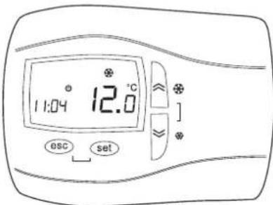
USER INTERFACE
Menu structure - Main controller
The control system is based on three menu with tree structure.
| Menu Access procedure Submenu Available functions | |||
| Operation mode | Press (prolonged) (ESC button associated function) (ESC button associated function) | Stby | Change operation mode |
| HEAt | |||
| COOL | |||
| UP button |  (UP button direct function) (UP button direct function) | - | Value increases, the next label |
| DOWN button | Press (DOWN button direct function) (DOWN button direct function) | - | Value decreases, the next label |
| Main view (disp) | Press (prolonged) (SET button direct function) (SET button direct function) | R1 | Analogue input display |
| rtC | Clock display | ||
| SEtP | Set point (set by customer) display | ||
| SEtr | Set point (actual set point) display | ||
| Menu | Access procedure | Submenu U | USER SER | VICE Available functions |
| Status | Pres | R , √ | Analogue input display | |
| d , √ | Digital input display | |||
| AO , √ | Analogue output display | |||
 | dO , √ | Digital output display | ||
| CL , √ | Date and hour adjustment | |||
| (SET button direct function) | SP | √ | HERC setpoint display | |
| √ | COOL setpoint display | |||
| Sr | √ | HERC actual setpoint display | ||
| √ | COOL actual setpoint display | |||
| Hr , √ | Compressors and pumps working hours display |
| Menu | Access procedure | Submenu U | USER SERVICE Available functions | ||
| Procedure | Pressure contemporary buttons + + (combined function ESC + SET button) (combined function ESC + SET button) | PRr | CL | √√ | |
| Cr | √ | ||||
| CE | √ | ||||
| CF | √√ | ||||
| U1 | √√ | ||||
| Er | √ | ||||
| St | √ | ||||
| CP | √ | ||||
| PI | √ | ||||
| FE | √ | ||||
| PE | √ | ||||
| H1 | √ | ||||
| HE | √ | ||||
| dF | √ | ||||
| dS | √ | ||||
| HP | √ | ||||
| PL | √ | ||||
| EE | √ | ||||
| AL | √ | ||||
| rC | √ | ||||
USER INTERFACE
| Menu | Access procedure | Sub-menu | USER | SERVICE | Available functions | SERVICE | Available functions |
| Programmation | FnC | DEF √ | Manual defrost | ||||
| tA √ | Silence alarms | ||||||
| St | OFF √ | Change in OFF state | |||||
| On √ | Change in status ON | ||||||
| CC | UL √ | Upload program parameters | |||||
| dL √ | Download the program parameters | ||||||
| Fr √ | Format Multi Function Key | ||||||
| Eur | √ | Reset historical alarms | |||||
| PASS | - √√ | Enter password | |||||
| EU | - √√ | Viewing historical alarms | |||||
| Alarm mute | Pressure contemporary buttons (combined function ESC + SET button) (combined function ESC + SET button) | -- | - | √√ | Alarm manual restore | ||
| Manual defrost | Long press button (UP button function associated) (UP button function associated) | -- | - | √√ | Enable manual defrost | ||
Press SET to go from one level to that below. Press ESC to go to higher level.
Press the UP and DOWN buttons respectively to scroll the menu up and down inside the same level.
Press the UP and DOWN buttons to modify the value of the selected parameter. Press SET to confirm the modification. Press ESC to not confirm the modification.
INPUTS AND OUTPUTS
Inputs and outputs
SB655 - main controller
XVD420 - electronic expansion valve driver
| COMP. | SB655 | SE655 | XVD420 | |
| VB - VD | IR | x | - | - |
| IR with electronic expansion valve (optional) | x | - | x | |
| IP | x | - | x | |
| VR | IR | x | x | - |
| IR with electronic expansion valve (optional) | x | x | x | |
x = Present
- = Not present
Analog input
| Analog inputs MAIN CONTROLLER (SB655) | ||
| DESCRIPTION CHARACTERISTICS | ||
| AI1 water inlet probe plant exchanger NTC temperature sensor (-50°C ÷ 99°C) | ||
| AI2 water outlet probe plant exchanger NTC temperature sensor (-50°C ÷ 99°C) | ||
| AI3 liquid probe NTC temperature sensor (-50°C ÷ 99°C) | ||
| AI4 | ATC / outside air probe / remote ST-BY - S/W.- demand limit-economy | NTC temperature sensor (-50°C ÷ 99°C) / digital input |
| AI5 see AI5 on “digital inputs” configured as digital input | ||
| - Input AI4 is factory-set as not enabled, if present ATC or SND accessory, input AI4 is pre-set by factory. Its configuration for specific use must be carried out at the time of installation according to the needs of the moment, modifying the configuration by parameter.- Input AI5 is factory-set as neutral and its configuration for specific use must be carried out at the time of installation according to the needs of the moment, modifying theconfiguration by parameter.Modification and parameter configuration operations must only be carried out by an authorised service centre or by competent personnel. | ||
| Analog inputs EXPANSION BOARD (SE655) | ||
| DESCRIPTION CHARACTERISTICS | ||
| AI1 Recovery water inlet probe exchanger NTC temperature sensor (-50°C ÷ 99°C) | ||
| AI2 Recovery water outlet probe exchanger NTC temperature sensor (-50°C ÷ 99°C) | ||
| Analog inputs ELECTRONIC EXPANION VALVE DRIVER (XVD420) | ||
| DESCRIPTION CHARACTERISTICS | ||
| AI1 | suction pression transducer | electronic transducer 4-20 mA (0 barg ÷ 30 barg) |
| AI3 suction temperature | NTC | temperature sensor (-50°C ÷ 99°C) |
Digital input
| Digital inputs MAIN CONTROLLER (SB655) | ||
| DESCRIPTION CHARACTERISTICS | ||
| DI1 | Thermal switch compressor 1 – thermostatted delivery 1 –high pressure switch | Digital input with voltage-free contact |
| DI2 | Thermal switch compressor 2 –thermostatted delivery 2 – high pressure switch | Digital input with voltage-free contact |
| DI3 | Low pressure switch + sequence meter + fan thermal switch + EEV driver alarm | Digital input with voltage-free contact |
| DI4 Thermal switch plant pump 1 Digital input with voltage-free contact | ||
| DI5 Thermal switch plant pump 2 (if present) Digital input with voltage-free contact | contact | |
| DI6 | Differential pressure switch + external paddle flow switch | Digital input with voltage-free contact |
| AI5-IN DIG | Remote ST-BY - S/W.- demand limit-economy | Analog input configured as digital |
| *refer to section alarms. ER10-ER11 for more detailsNote for input DI5 thermal switch pump 2.If only one pump is used and only one thermal switch is required, ID5 can be used as an additional multiconf. input for Remote ST-BY - S/W.- demand limit - economy.In this way it is possible to have both the- remote ST-BY, and- S/W - demand limit – economy- External probeDI5 is factory-configured as pump 2 thermal switch. To modify the configuration, refer to the section “configurable inputs setting”. | ||
INPUTS AND OUTPUTS
| Recovery digital inputs EXPANSION BOARD (SE655) | ||
| DESCRIPTION CHARACTERISTICS | ||
| DI1 Recovery ON-OFF Enable Digital input with voltage-free contact | ||
| DI2 | Recovery differential pressure switch + paddle flow switch | Digital input with voltage-free contact |
| DI3 | Recovery thermal switch pump 1 | Digital input with voltage-free contact |
| Digital inputs ELECTRONIC EXPANION VALVE DRIVER (XVD420) | ||
| DESCRIPTION CHARACTERISTICS | ||
| DI1 Enabling regulation | Digital input with voltage-free contact | |
Analog output
| Analog outputs MAIN CONTROLLER (SB655) | |
| DESCRIPTION CHARACTERISTICS | |
| A01 Fans pwm signal for control of single-phase fans in phase cut | |
| A04 Fans signal 0-10V for control of three-phase fans in phase cut | |
| A05 Modulating plant pump signal 4...20mA for inverter control pump | |
Digital output
| Digital outputs MAIN CONTROLLER (SB655) | ||
| DESCRIPTION CHARACTERISTICS | ||
| DO1 | Compressor 1 2A resistive relays - 230Vac | |
| DO2 | Compressor 2 2A resistive relays - 230Vac | |
| DO3 | Reverse cycle valve 2A resistive relays - 230Vac | |
| DO4 | Antifreeze resistance – support 1st step 2A resistive relays - 230Vac | |
| DO5 | Resistance support 2nd step Open collector - 12Vcc max 35mA | |
| DO6 | Alarm relay 2A resistive relays - 230Vac | |
| AO2 | Relay plant pump 1 (using 12Vdc external relay) Open collector - 12Vcc max 35mA | |
| AO3 | Relay plant pump 2 (using 12Vdc external relay) 0 - 10Vdc output - max 28mA | |
| Note: AO2 is analog output configured as digital | ||
| Digital outputs EXPANSION BOARD (SE655) | ||
| DESCRIPTION CHARACTERISTICS | ||
| DOE1 | Recovery reverse cycle valve 2A resistive relays | |
| DOE2 | Recovery relay pump 1 2A resistive relays | |
| Digital outputs ELECTRONIC EXPANION VALVE DRIVER (XVD420) | ||
| DESCRIPTION CHARACTERISTICS | ||
| DO1 | Alarms | 5A resistive relays - 250Vac |
CONTROLLER TECHNICAL DATA
Main controller SB655 technical data
| Description Typical Minimum Maximum | |||
| Power supply voltage 12-24 V~ 10,8-21,6 V~ 13,2-26,4 V~ | |||
| Power supply frequency 50 Hz / 60 Hz - - | |||
| Power 6 VA - - | |||
| Insulation class 2 - - | |||
| Protection rating Frontal IP65 - - | |||
| Ambient operating temperature | 25 °C | -10 °C | 60 °C |
| Ambient operating humidity (non-condensing) | 30 % | 10 % | 90 % |
| Ambient storage temperature | 25 °C | -20 °C | 85 °C |
| Ambient storage humidity (non-condensing) | 30 % | 10 % | 90 % |
Expansion board SE655 technical data
| Description Typical Minimum Maximum | |||
| Power supply voltage | 12-24 V~ 10,8-2 | 1,6 V~ | 13,2-26,4 V~ |
| Power supply frequency | 50 Hz / 60 Hz | -- | |
| Power | 5 VA | -- | |
| Insulation class 2 | -- | ||
| Protection rating | Frontal IP0 | -- | |
| Ambient operating temperature | 25 °C | -10 °C | 60 °C |
| Ambient operating humidity (non-condensing) | 30 % | 10 % | 90 % |
| Ambient storage temperature | 25 °C | -20 °C | 85 °C |
| Ambient storage humidity (non-condensing) | 30 % | 10 % | 90 % |
Electronic expansion valve driver EEV - XVD420 technical data
| Description | Typical Minimum Maximum | ||
| Power supply voltage | 24 V~ / -- | - | - |
| Power supply frequency 50 Hz / 60 Hz - - | |||
| Power | 30 VA - 25Watt | - - | |
| Protection rating | 2 - - | ||
| Ambient operating temperature | 25 °C | -5 °C | 55 °C |
| Ambient operating humidity (non-condensing) | 30 % | 10 % | 90 % |
| Ambient storage temperature | 25 °C | -20 °C | 85 °C |
| Ambient storage humidity (non-condensing) | 30 % | 10 % | 90 % |
ALARMS
Alarm activation and reset
The controller can perform a complete diagnosis of the unit, detecting all operation faults and signalling a number of alarms.
Activation of an alarm involves :
- blocking of users concerned
- signalling of alarm code on the display (in case of simultaneous alarms the one with the lowest index is displayed whereas the complete list of active alarms can be shown by accessing the "Status \RL") menu
• recording of event in the alarms history
Alarms that can damage the unit or system require manual resetting or an action by the operator to reset the controller (pressing the UP and DOWN buttons at the same time). It is advisable to carefully check the cause of the alarm and make sure the problem is eliminated before restarting the unit. In any case the unit restarts only if the cause of the alarm has ended.
Less critical alarms are automatic reset. As soon as the cause is eliminated the unit starts working again and the alarm code disappears from the display. Some of these alarms become manual reset if the number events per hour exceeds a fixed limit.
Press any button to deactivate the alarm : alarm signalling disappears from the display, the alarm LED starts flashing and the Alarm digital output is disabled. This operation does not affect the alarm in progress.
Number of events per hour
The counting of events per hour is provided for some alarms : if the number of events reaches a fixed limit in the last hour, the alarm goes from automatic to manual reset.
Sampling of alarms occurs every 112 seconds. If an alarm is activated several times in a sampling period (112 seconds) it is counted only once.
Example. If an number of events per hour equal to 3 is set, it must have a duration of between 2*112 seconds and 3*112 seconds so that the alarm goes from automatic to manual reset.
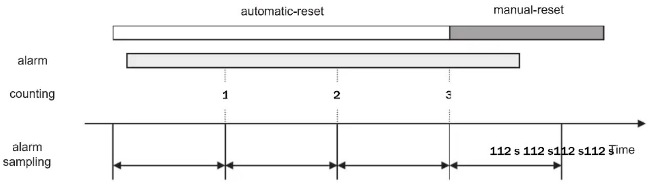
bar_stacked
| Event Type | Start Time | End Time | | ---------------- | ---------- | -------- | | automatic-reset | 1 | 3 | | manual-reset | 1 | 3 | | alarm counting | 1 | 2 | | alarm sampling | 112 s | 112 s |Alarms history
The controller enables the recording of alarms occurring during unit operation (up to a max. of 99 events). The following are memorised for each event :
- alarm code
- input time
- input date
- output time
- output date
- type of alarm (automatic or manual reset)
This information can be shown by accessing the "Programming \EU" menu.
When the number of events memorised is more than 99, alarm Er-90 is generated and the subsequent events are memorised overwriting the oldest alarms.
The alarms history can be cancelled by means of the Eur function available inside the "Programming Fon " menu.
ALARMS
Alarm table
| Code Alarm | Type of alarm | input | COMPRESSORS | FANS | PLANT CIRCUIT PUMPS | EXCHANGER RESISTANCES PLANT | AUXILIARY OUTPUT | ||
| Er05 | Low pressure + sequence meter + fans thermal switch + EEV driver alarm (if present) | A/M(2) | DI3 OFF | OFF | |||||
| Er10 | Compressor 1 thermal protection | High pressure | M DI1 | OFF comp.1 | |||||
| Er11 | Compressor 2 thermal protection | M DI2 | OFF comp.2 | ||||||
| Er20 | Plant circuit water differential pressure switch / paddle switch | A/M | DI6 OFF | OFF if manual reset | OFF | ||||
| Er21 | Plant circuit pump 1 thermal protection | M DI4 OFF | OFF OFF p.1 | OFF | |||||
| Er22 | Plant circuit pump 2 thermal protection | M DI5 OFF | OFF OFF p.2 | OFF | |||||
| Er25 | Recovery water differential pressure switch / paddle switch | M DIE2 OFF | OFF ON | OFF | |||||
| Er26 | Recovery pump 1 thermal protection | M DIE3 OFF | OFF ON | OFF | |||||
| Er30 | Plant circuit antifreeze | M AI2 OFF | |||||||
| Er31 | Recovery circuit antifreeze | M | AIE2 | OFF | |||||
| Er45 | Clock fault error | A | |||||||
| Er46 | Clock to be set error | A | |||||||
| Er47 | Remote keyboard communication error | A | |||||||
| Er60 | Plant exchanger inlet water probe fault | A | AI1 | OFF | OFF OFF | OFF | OFF | ||
| Er61 | Plant exchanger outlet water probe fault | A | AI2 | OFF | OFF OFF | OFF | OFF | ||
| Er62 | Liquid temperature probe | A | AI3 | ||||||
| Er63 | Recovery exchanger inlet water probe fault | A | AI1 | OFF | OFF OFF | OFF | OFF | ||
| Er64 | Recovery exchanger outlet water probe fault | A | AI2 | OFF | OFF OFF | OFF | OFF | ||
| Er68 | External air probe fault | A | AI4 | ||||||
| Er80 | Configuration error | A | OFF | OFF OFF | OFF | OFF | |||
| Er90 | Recordings for alarms history exceeded signalling | M | |||||||
Notes:
(1) A = automatic reset, M = manual reset
(2) Only when the alarm becomes manual reset
E-05 Low pressure – Sequence meter - Fans thermal protection - EEV driver alarm
The alarm becomes manual reset when the number of events per hour is more than parameter RL 12.
The alarm is bypassed for parameter RL 11 seconds from activation of the compressor or the reverse cycle valve.
Er 10 Compressor 1 thermal protection
The manual-reset alarm intervenes in the event of activation of the compressor thermal protection or the thermostat located on the outlet of the compressor.
Er 11 Compressor 2 thermal protection
The manual-reset alarm intervenes in the event of activation of the compressor thermal protection or the thermostat located on the outlet of the compressor.
Er 10 Er 11\* Compressor 1 thermal protection - Compressor 2 thermal protection - High pressure switch (PAA)
The manual-reset alarm intervenes in the event of activation of the compressor 2 thermal protection or the thermostat located on the outlet of the compressor 2 AND in the event of activation of the compressor 1 thermal protection or the thermostat located on the outlet of the compressor 1 and/or more likely it means the auto-reset high pressure switch (PAA) trips in.
Er20 / Er25 Differential pressure switch - flow switch plant / recovery
The alarm is activated if the associated digital input remains activated for at least 5 seconds and automatically resets if the digital input remains not activated for at least 3 seconds. The alarm becomes manual reset if the digital input remains activated for more than 10 seconds. The alarm is bypassed for 15 seconds from pump activation.
Er 21 Er22 / Er26 Pump thermal protections plant / recovery
When thermal protection trip in the controller stop the pump and the unit; if the controller manages two pumps it involves the activation of the other, if both thermal protection trip in the controller stops the unit.
ALARMS
Er20 Er25 Flow switch / water differential pressure switch alarm
Unit with 1 pump:
The alarm s active if the input is active for at least the time RL 15 (plant) / RL 18 (source). It remains automatic for the time RL 16 (plant) / RL 19 (source): if, during this time the alarm is deactivated the unit can restart to work, instead if remains active becomes manual.
Unit with 2 pumps:
The alarm s active if the input is active for at least the time RL 15 (plant) / RL 18 (source). It remains automatic for the time RL 16 (plant) / RL 19 (source): during this time the controller stops the working pump and switch on the other one, if the alarm is deactivated the unit can restart to work, instead if remains active becomes manual.
1 PUMP : PLANT / RECOVERY
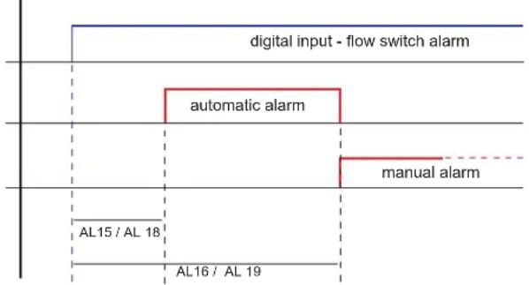
flowchart
graph TD
    A["digital input - flow switch alarm"] --> B["automatic alarm"]
    B --> C["manual alarm"]
    D["AL15 / AL 18"] --> E["AL16 / AL 19"]
    E --> F["End"]
2 PUMPS : PLANT / RECOVERY

flowchart
graph TD
    A["digital input - flow switch alarm"] --> B["automatic alarm"]
    B --> C["pump switch"]
    C --> D["manual alarm"]
    D -.-> E["AL16 / AL 19"]
    E --> F["AL15 / AL 18"]
If there is the flow switch alarm during the first startup of the unit control the cleaness of the water plant.
Particularly diring the startup a lot of impurities due to the pipes installation can be present into the hydraulic plant
and if the plant was not carefully washed, despite the installation of water filters
with adequate mesh size impurities as sand,
chips or similar could enter into the exchangers choking them and, in worst cases,
lead to a serious damage or broke for freezing (if the excahanger is working as evaporator).
Er-30 / Er-31 Antifreeze plant / recovery
The alarm switch off the compressors, activates the heaters and the pumps (if off).
It is a very dangerous alarm: check carefully the possible cause and eliminates it before reset the alarm.
Er45 Clock failure
If the clock is not working it is not possible to set time bands and the record of date and hour for the alarms present in the alarm events.
Er46 Alarm: clock to be set
There is this alarm if the controller is not electrically supplied for several days.
E-47 LAN communication error between electronic controller (base, remote, expansion)
There is this alarm if there si not communication between the devices connected through LAN.
Er60 Er61 Er63 Er64 Failure of temperature probes (plant and recovery)
This alarm stops the unit. It could be caused for short-circuit, breakage or out of range of the probe
Er-62 Failure of liquid temperature probe
If the alarm is active the fans work only on-off on request (on when compressor is on). It could be caused for short-circuit, breakage or out of range of the probe. In and out defrosting are managed by the timing of compressor.
Er-68 Failure of external air temperature probe
If the alarm is active all controls based on this probe (i.e. dynamic setpoint or defrost) are disabled: the unit can continue to work. It could be caused for short-circuit, breakage or out of range of the probe.
Er-80 Configuration fault
Appears when the parameters are not set correctly.
Er90 Maximum number of recordings in alarms history exceeded
Indicates that the alarms history buffer is full. Every new alarm will be memorised, cancelling the oldest alarm.
* Note: The manual-reset high pressure (PAM) does not have reference on the control display so you can not identify it through the internal diagnostics as it acts directly on contactors, it may happen that the control display does not signal any error but the compressors are however still, in this case switch-off the unit then rearm the manual-reset high pressure switch by pressing the button located at the top of the switch.
ALARMS
Electrical expansion valve table alarm XVD420
| Code | Driver input | Allarm Cause Effect | Alarm type | Alarm on main controller | Input on main controller | Troubleshooting | |
| Er01 | AI1 Probe AI1 fault | Probe fault / shortcircuit / non connected | Valve closed | Automatic er05 DI3 | Check wiring of the probe, replace probe AI1 | ||
| Er03 | AI3 Probe AI3 fault | Probe fault / shortcircuit / non connected | Valve closed | Automatic er05 DI3 | Check wiring of the probe, replace probe AI3 | ||
| Er06 | AI1 - AI3 | Errore uscita saturazione | Probe AI1 AI3 fault / shortcircuit / non connected | Valve closed | Automatic er05 DI3 | Check wiring of the probe, replace probe AI1 AI3 | |
| Er07 | - MOP alarm | Saturation temperature > setpoint MOP 20°C for more than 255 s | Valve closed | Automatic er05 DI3 | Wait for saturation temperature < 20°C | ||
| Er10 | - NO link alarm | Serial communication fault | Valve closed | Automatic er05 DI3 Re-establish connection | |||
| Er11 | W2- W2+ W1- W1+ | Motor protection alarm | Excedeed absorbed current | Valve closed | Manual * er05 DI3 | Check motor phases, motor connections | |
| Er12 | W1- W1+ | Motor protection alarm | Disconnection winding 1 | Valve closed | Manual * er05 DI3 | Check winding connection 1 (terminals 6-7) | |
| Er13 | W1- W1+ | Motor protection alarm | Shortcircuit winding 1 | Valve closed | Manual * er05 DI3 | Check winding connection 1 (terminals 6-7) | |
| Er14 | W2- W2+ | Motor protection alarm | Disconnection winding 2 | Valve closed | Manual * er05 DI3 | Check winding connection 2 (terminals 4-5) | |
| Er15 | W2- W2+ | Motor protection alarm | Shortcircuit winding 2 | Valve closed | Manual * er05 DI3 | Check winding connection 2 (terminals 4-5) | |
Note:
* power off and on the driver/unit to reset
AVAILABLE FUNCTIONS
ST-BY of the unit
When the unit is powered it may be in STAND BY status (the display shows the message Stby) or ON status. It is possible to switch between ON and STAND BY by pressing (prolonged) the MODE button.
When the unit is STAND BY all the users are disabled and the antifreeze function is not activated.
Operation mode selection
When the unit is ON, one of the operation modes can be selected by accessing the "Operation mode" menu.
- Cooling COOL
- Heating ⚙️ HERE
- STAND BY ⏻ 5tdby
Remote ST-BY
This function allows remote selection of the STANDBY mode. If the input is activated (contact open) the controller is in STANDBY mode and the operation mode cannot be modified from keyboard.
The function is available if one of the configurable inputs is configured for this, contact closed = unit ON (display SIW), contact open = STAND-BY (display 5E d6y).
Working mode remote change-over cooling / heating
This function allows remote selection of Cooling or Heating mode. If the input is activated (contact open) the unit is in heating mode. If the input is not activated (contact closed) the unit is in cooling mode. The operation mode cannot be modified from the keyboard (but STANDBY mode can be selected).
To enable this function, follow the indications in the section "configurable inputs setting".
Set point
The set point value in cooling (COOL) and heating (HERE) can be set by accessing the "Status \ Sp" menu. The purpose of the controller is to keep the water temperature at the unit inlet as close as possible to the set value, by activating the compressor according to an on-off logic.
Note for heat pump mode:
It's possible to set a value for outside air temperature (parameter HP11) below which the heat pump operation is stopped (still available, if any, additional integrative heaters).

line
| Set-point COOL tr 10 | Compressors steps | | ------------------- | ----------------- | | tr 13 | 1 | | tr 14 | 2 |
line
| Temperature Threshold | Gonlprisacopress steps | | ---------------------- | ----------------------- | | tr24 | 2 | | tr23 | 1 | | temp. AI1 | 1 | | Set-point HERC | 0 | | tr20 | 0 |Antifreeze
The plate-type exchanger is protected by activation of an electrical heating element and activation of the antifreeze alarm, occurring in sequence when the exchanger outlet water temperature reaches dangerous values. The storage tank is protected by the antifreeze heater (accessory) activated in parallel with the plate-type exchanger heating element.
Supplementary electrical heating elements
The parameter H120 enables operation of the electrical elements supplementing the heat pump when it assumes value 1. The heating elements are activated according to a two-step logic depending on the unit inlet water temperature. When present, the heating elements also carry out a storage tank antifreeze function.

line
| Temp. Al2 | AntifreezeSignal | | :--- | :--- | | ON | Off | | RL51 | Off | | RL52 | Off |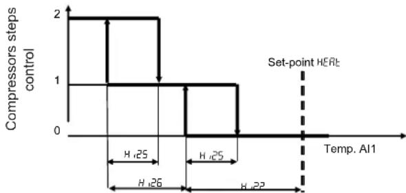
line
| Temp. Al1 | Compressors steps control | | --------- | ------------------------- | | 0 | 2 | | 0.25 | 1 | | 0.26 | 0 | | 0.27 | 0 | | 0.28 | 0 |AVAILABLE FUNCTION
Dinamic setpoint
The parameter d500 allows the dynamic setpoint; if d500=1 the setpoint is corrected as a function of external air temperature (if present). To set the external air temp follow the indications of the section "Configurable Inputs".
The activation of the dynamic setpoint is displayed by the switch-on of the led Economy on the display (money box symbol); it is possible to display the actual setpoint by the parameter 5Etr.
Dinamic setpoint in heating mode
It is possible to modify setpoint (d506 in °C), the proportional band (d502 in °C), and the maximum differential (d504 in °C)

line
| Temp. aria esterna AI4 o AI5 | Set-point HERc | | --------------------------- | -------------- | | d504 | d504 | | d506 | d502 | | d506 | HERc | | d506 | d502 positive |Dinamic setpoint in cooling mode
It is possible to modify setpoint (d505 in °C), the proportional band (d501 in °C), and the maximum differential (d503 in °C)

line
| Temperature | Cooling Rate | |-------------|--------------| | dSO₃ | dSO₃ | | dSO₄ | dSO₄ | | dSO₅ | dSO₅ | | dSO₆ | dSO₆ |Plant pump on-off control
Pre-pumping: when the unit is switched fromn STD-BY to COOL or HEAT mode firstly the pump is activated and, if there is no alarm, after the time of parameter PI 20 the first compèressor can start-up.
Post-pumping: when the unit is switched from COOL or HEAt mode to STD-BY firstly the compressors are switched-off and after the time of parameter P1 ≥ 1 , the pump is switched off.
If the pump is ON is always working at 100%.
Plant pump modulating control
If the pump is driven by inverter (or similar modulating system) is possible to set the velocity between 30% and 100% of the maximum velocity modifying the parameters P1 I in cooling, P1 I in heating.
For instance with P1 3 l=70 and P1 4 l=75 the velocity will be 70% in cooling and 75% in heating
Note: When the compressors are off the pump works at minimum velocity.
Referring pre and post pumping the pump is managed as in on-off mode
Demand limit
Basing on the state of a digital input, this function allows to force the unit to work with only 1 compressor, so reducing the power input demand.
To enable this function follow the indications of the section "Configurable Inputs".

line
| Signal | Description | |--------|-------------------------------------| | Top | digital input Demand Limit | | Bottom | compressors steps disabling |Funzione economy
Basing on the state of a digital input, this function allows to modify the setpoint.
In cooling mode the setpoint is increased of the value of the parameter tr 15 (es. tr 15 + 5 °C).
In heating mode the setpoint is decreased of the value of the parameter tr25 (es. tr25 - 6°C )
To enable this function follow the indications of the section "Configurable Inputs"- "Economy".
The activation of the Economy function is displayed by the switch-on of the led Economy on the display (money box symbol); it is possible to display the actual setpoint by the parameter SETtr.
The enabling of the Economy function has to be done considering the following scheme:
Cooling mode COOL:
£r 15 usually positive value
tr 10 set-point COOL

line
| Time Segment | Event Type | Value | | ------------ | ---------- | ----- | | Start | Digital input | ON | | Off | Digital input | OFF | | End | Digital input | ON | | Set-point | Set-point | Er 10 + Er 15 | | End | Set-point | Er 15 |Heating mode HERE:
tr25 usually negative value
E-20 set-point HEAE

other
| State | Time Segment | Description | |-------------|--------------|---------------------| | ttr20 | 1 | Start of set-point | | ttr20 | 2 | End of set-point | | ttr20 | 3 | End of set-point | | ttr20 | 4 | End of set-point | | ttr20 | 5 | End of set-point | | ttr20 | 6 | End of set-point | | ttr20 | 7 | End of set-point | | ttr20 | 8 | End of set-point | | ttr20 | 9 | End of set-point | | ttr20 | 10 | End of set-point | | ttr20 | 11 | End of set-point | | ttr20 | 12 | End of set-point | | ttr20 | 13 | End of set-point | | ttr20 | 14 | End of set-point | | ttr20 | 15 | End of set-point | | ttr20 | 16 | End of set-point | | ttr20 | 17 | End of set-point | | ttr20 | 18 | End of set-point | | ttr20 | 19 | End of set-point | | ttr20 | 20 | End of set-point | | ttr20 | 21 | End of set-point | | ttr20 | 22 | End of set-point | | ttr20 | 23 | End of set-point | | ttr20 | 24 | End of set-point | | ttr20 | 25 | End of set-point | | ttr20 | 26 | End of set-point | | ttr20 | 27 | End of set-point | | ttr20 | 28 | End of set-point | | ttr20 | 29 | End of set-point | | ttr20 | 30 | End of set-point | | ttr20 | 31 | End of set-point | | ttr20 | 32 | End of set-point | | ttr20 | 33 | End of set-point | | ttr20 | 34 | End of set-point | | ttr20 | 35 | End of set-point | | ttr20 | 36 | End of set-point | | ttr20 | 37 | End of set-point | | ttr20 | 38 | End of set-point | | ttr20 | 39 | End of set-point | | ttr20 | 40 | End of set-point | | ttr20 | 41 | End of set-point | | ttr20 | 42 | End of set-point | | ttr20 | 43 | End of set-point | | ttr20 | 44 | End of set-point | | ttr20 | 45 | End of set-point | | ttr20 | 46 | End of set-point | | ttr20 | 47 | End of set-point | | ttr20 | 48 | End of set-point | | ttr20 | 49 | End of set-point | | ttr20 | 50 | End of set-point | | ttr20 | 51 | End of set-point | | ttr20 | 52 | End of set-point | | ttr20 | 53 | End of set-point | | ttr20 | 54 | End of set-point | | ttr20 | 55 | End of set-point | | ttr20 | 56 | End of set-point | | ttr20 | 57 | End of set-point | | ttr20 | 58 | End of set-point | | ttr20 | 59 | End of set-point | | ttr20 | 60 | End of set-point | | ttr20 | 61 | End of set-point | | ttr20 | 62 | End of set-point | | ttr20 | 63 | End of set-point | | ttr20 | 64 | End of set-point | | ttr20 | 65 | End of set-point | | ttr20 | 66 | End of set-point | | ttr20 | 67 | End of set-point | | ttr20 | 68 | End of set-point | | ttr20 | 69 | End of set-point | | ttr20 | 70 | End of set-point | | ttr20 | 71 | End of set-point | | ttr20 | 72 | End of set-point | | ttr20 | 73 | End of set-point | | ttr20 | 74 | End of set-point | | ttr20 | 75 | End of set-point | | ttr20 | 76 | End of set-point | | ttr20 | 77 | End of set-point | | ttr20 | 78 | End of set-point | | ttr20 | 79 | End of set-point | | ttr20 | 80 | End of set-point | | ttr20 | 81 | End of set-point | | ttr20 | 82 | End of set-point | | ttr20 | 83 | End of set-point | | ttr20 | 84 | End of set-point | | ttr20 | 85 | End of set-point | | ttr20 | 86 | End of set-point | | ttr20 | 87 | End of set-point | | ttr20 | 88 | End of set-point | | ttr20 | 89 | End of set-point | | ttr20 | 90 | End of set-point | | ttr20 | 91 | End of set-point | | ttr20 | 92 | End of set-point | | ttr20 | 93 | End of set-point | | ttr20 | 94 | End of set-point | | ttr20 | 95 | End of set-point | | ttr20 | 96 | End of set-point | | ttr20 | 97 | End of set-point | | ttr20 | 98 | End of set-point | | ttr20 | 99 | End of set-point | | ttr20 | 100 | End of set-point | Interesso digitalInput Economy Interesso digitalInput Economy Interesso digitalInput Economy Interesso digitalInput Economy Interesso digitalInput Economy Interesso digitalInput Economy Interesso digitalInput Economy Interesso digitalInput Economy Interesso digitalInput Economy Interesso digitalInput Economy Interesso digitalInput Economy Interesso digitalInput Economy Interesso digitalInput Economy Interesso digitalInput Economy Interesso digitalInput Economy Interesso digitalInput Economy Interesso digitalInput Economy Interesso digitalOutput Economy Interesso digitalOutput Economy Interesso digitalOutput Economy Interesso digitalOutput Economy Interesso digitalOutput Economy Interesso digitalOutput Economy Interesso digitalOutput Economy Interesso digitalOutput Economy Interesso digitalOutput Economy Interesso digitalOutput Economy Interesso digitalOutput Economy Interesso digitalOutput Economy Interesso digitalOutput Economy Interesso digitalOutput Economy Interesso digitalOutput Economy Interesso digitalOutput Economy Interesso digitalOutput Economy Interssso DigitalInput Economy Interssso DigitalInput Economy Interssso DigitalInput Economy Interssso DigitalInput Economy Interssso DigitalInput Economy Interssso DigitalInput Economy Interssso DigitalInput Economy Interssso DigitalInput Economy Interssso DigitalInput Economy Interssso DigitalInput Economy Interssso DigitalInput Economy Interssso DigitalInput Economy Interssso DigitalInput Economy Interssso DigitalInput Economy Interssso DigitalInput EconomyRecording hours of operation
The controller can record the hours of compressors and pumps operation. Access the "Status \ Hr" menu to show the values.
Power failure
In case of a power failure, when the power is restored the controller will go to the status prior to the power failure. The procedure is cancelled if a defrost is in progress. All timing in progress is cancelled and reinitialised.
Clock
The controller has an internal clock for memorising the date and time of each alarm occurring during unit operation (see "Alarms history"). The clock can be set by accordingly to "Date and time set up".
History alarms
The controller is able to log and save up to 90 alarm events. Alarms are visible in the menu "Par \ EU".
Push SET to display alarm EUOO (if present) that is always the latest, EUO I is the one before and so on.
Scroll to UP and DOWN keys to display all the other alarms, push SET to display more information about the event chosen: alarm code (see alarm table), start event time, start event date, stop event time, stop event date, type of alarm (automatic or manual reset).
Example of an alarm visualization:
alarm event EUO1
L alarm code Er01
L start event time 20:01
L start event date 28.03
L stop event time 20:09
L stop event date 28.03
L type of alarm RUEo / TANU
Total recovery function (VR unit only)
The recovery function thermoregulates on the inlet water AIE1 probe. If there is no demand for cooling power recovery can not be activated.
The parameters to adjust are:
r[0] recovery set point
r-CO2 recovery differential

line
| Sonda ingresso Recupero AIE1 | Set point Recupero rCOI | | :--- | :--- | | Rec ON | :--- | | Rec OFF | :--- | | rc02 | :--- | | 01 | Set point Recupero rCOI |AVAILABLE FUNCTION
Automatic change-over
This function is present in the heat pump unit.
The automatic change-over function is enable by 5±0.1 parameter - Enable change analogue input setting.
5E01 = 0 automatic change-over disable
5601 = 1 automatic change-over enable
The automatic change-over can take place from the analog signal of the probe set by parameters 5802 - probe selection for automatic change-over:
5602 = 0 outdoor air temperature
5602 = 1 inlet water temperature plant exchanger
5t02 = 2 outlet water temperature plant exchanger
The entrance in cooling and heating mode with two different differentials set by parameter 5E03 - Differential for automatic chan-over in heating - and 5E04 Differential for automatic chan-over in cooling
In the neutral zone (between the two set-point) mode can also be set by key.
Following an example of automatic change-over based on external air temperature (5±0.2 = 0)

Set point COOL and set point HEAT are the real set-point and can differ from set-point tr10 and tr20 due to climatic regulation enabled (economy function and dynamic set point)
Note:
- 5604 is summed to set point COOL; 5603 is summed to set point HEAT.
- (5≤ 03 + 5≤ 04) < (Set HEAT - Set COOL) , otherways the sum of the absolute value of the two differential may not overcome the value of (Set HEAT - Set COOL).
Date and time set up
The electronic controller is equipped with internal clock (RTC) that allows to record in the alarm events date and hour of each alarm.
To modify date and hour, starting from the main view on the display, press the SET button.
A single pressure of the button SET enter the view of different folders.
Scroll the menu using UP and DOWN buttons until find the folder CL.
Press the SET button to enter in the menu.
Now in the display you have the label HOUR. You can choose to set hour, date and year scrolling the menu using UP and DOWN buttons.
Press the SET button for 3 seconds and enter in the modification menu.
To set hour, date and year it will be enough scroll UP and DOWN until the selected value, then press SET button.
To exit from the clock adjustment menu press the ESC button until arrive to main view on the display.
AVAILABLE FUNCTION
Timer scheduling
The scheduling allows to set weekly time zones to obtain a reduce in energy consumption when the cooling or heating demand is lower.
There are 3 time zones each one with 4 events per hour.
For each event, you can set hours and minutes of start and stop, an operating mode (Stand-by or ON), a cooling set point and a heating set point.
ATTENTION: you can not change the operating mode via scheduling. The operating mode (cooling or heating) will be the same adopted before the enabling of time scheduling.
To enable time scheduling you must set up the date and time into the controller
The parameters for the scheduling can be accessed in the "tE" (time event) folder.
Enabling
The function can be enabled with the parameters tE00 - Enabling scheduling
| Parameters | descriptions | Value | |
| tEOO | Enabling scheduling | Scheduling disabled | 0 |
| Scheduling enabled 1 | |||
Management time
For each day of the week you can select one of the 3 time zone available
| Parameters day | Time zone | |||
| tE01 Monday | 1 2 3 | |||
| tE02 Tuesday | 1 2 3 | |||
| tE03 Wednesday | day 1 2 3 | |||
| tE04 Thursday | 1 2 3 | |||
| tE05 Friday 1 | 2 3 | |||
| tE06 Saturday | 1 2 3 | |||
| tE07 | Sunday | 1 2 3 | ||
For each time zone you can associate 4 events.
The parameters involved in time events are described below:
Event hour start time
It determines the hour of the start of the event [0-23]
Event minute start time
It determines the minutes of the start of the event [0-59]
Operating Mode ON/Standby
It determines the operating mode during the event
• 0 = ON
- 1 = Stand-by
Set point Cool
It determines the set point in cooling mode that will be set if the unit is in cooling mode before time scheduling
Set point Heat
It determines the set point in heating mode that will be set if the unit is in heating mode before time scheduling
AVAILABLE FUNCTION
Summary parameters table for time scheduling
| Descrizione Profilo 1 Profilo 2 Profilo 3 | |||||
| EVENT 1 | tE 10._tE 14 tE 38._tE 42 tE 66._tE 70 | ||||
| Hour / minutes tE 10._tE 11 tE 38._tE 39 tE 66._tE 67 | |||||
| Mode operating ON/Standby tE 12 | tE 40 tE 68 | ||||
| SetPoint Cool tE 13 tE 41 tE 69 | |||||
| SetPoint Heat tE 14 tE 42 tE 70 | |||||
| EVENT 2 | tE 17._tE 21 tE 45._tE 49 tE 73._tE 77 | ||||
| Hour / minutes tE 17._tE 18 tE 45._tE 46 tE 73._tE 74 | |||||
| Mode operating ON/Standby tE 19 | tE 47 tE 75 | ||||
| SetPoint Cool tE 20 tE 48 tE 76 | |||||
| SetPoint Heat tE 21 tE 49 tE 77 | |||||
| EVENT 3 | tE 24._tE 28 tE 52._tE 56 tE 80._tE 84 | ||||
| Hour / minutes tE 24._tE 25 tE 52._tE 53 tE 80._tE 81 | |||||
| Mode operating ON/Standby tE 26 | tE 54 tE 82 | ||||
| SetPoint Cool tE 27 tE 55 tE 83 | |||||
| SetPoint Heat tE 28 tE 56 tE 84 | |||||
| EVENT 4 | tE 31._tE 35 tE 59._tE 63 tE 87._tE 91 | ||||
| Hour / minutes tE 31._tE 32 tE 59._tE 60 tE 87._tE 88 | |||||
| Mode operating ON/Standby tE 33 | tE 61 tE 89 | ||||
| SetPoint Cool tE 34 tE 62 tE 90 | |||||
| SetPoint Heat tE 35 tE 63 tE 91 | |||||
Example of timer scheduling:
You choose to set time zone 1 from Monday to Friday with the following setup:
At 07.30 you put the unit ON with a set point of 12°C in cooling mode, and 40°C in heating mode
At 12.30 you change the set point to 14° C in cooling mode, 37° C in heating mode
At 13.30 you change the set point to 12°C in cooling mode, 40°C in heating mode
At 18.00 you put the unit in stand-by
You have to set the following parameters:
tEOO=1 enabling scheduling
tEO1, tEO2, tEO3, tEO4, tEO5, = 1 time zone 1
EVENT 1 – unit ON
E 10=8 hour
E E 11=30 minutes
E 12=0 ON, unit is ON (pay attention: 0=ON, 1=stand-by)
E 13= 12 set point cool 12°C
EE 14=40 set point heat 40°C
EVENT 2 – change set point
E17=12 hour
E18=30 minutes
E19=0 ON, unit is ON (pay attention: 0=ON, 1=stand-by)
E 20=12 set point cool 14°C
EE 21=40 set point heat 37°C
EVENT 3 – change set point
E 24=13 hour
E 25=30 minutes
E 26=0 ON, unit is ON (pay attention: 0=ON, 1=stand-by)
E27=12 set point cool 12°C
E 28=40 set point heat 40°C
EVENT 4 – unit in stand-by
E 31=18 hour
E 32=00 minutes
E 33=1 stand-by, unit is in stand-by (pay attention: 0=ON, 1=stand-by)
E 34=12 set point cool 12°C
E 35=40 set point heat 40°C
The operating mode (cooling or heating) adopted is the one already active before the event happens.
For Saturday or Sunday you can choose time zone 1 or another time zone (2 or 3) and set the parameters in a similar manner as described in this example.
PARAMETERS
Common parameters
| Description Unit Min Max | default value | Protection | |||
| TR10 - Temperature controller setpoint in COOL °C 7 27 9 3 | |||||
| TR13 - Temperature control hysteresis | °C 0.1 | 25.5 1 2 | |||
| TR14 - Steps/compressors insertion differential | °C 0.1 | 25.5 2.5 | 2 | ||
| TR15 - Setpoint differential in Cool from economy input | °C | -25.5 | 25.5 | 5 | 1 |
| TR20 - Temperature controller setpoint | °C | 28 | 53 | 43 | 3 |
| TR23 - Temperature control hysteresis | °C 0.1 | 25.5 1 2 | |||
| TR24 - Steps/compressors insertion differential | °C 0.1 | 25.5 2.5 | 2 | ||
| TR25 - Setpoint differential in Heat from economy input | °C | -25.5 | 25.5 | -5 | 1 |
| dS01 - Temperature controller dynamic differential proportional band in Cool | °C | -50 | 99.9 | -10 | 1 |
| dS02 - Temperature controller dynamic differential proportional band in Heat | °C | -50 | 99.9 | 10 | 1 |
| dS03 - Maximum temperature controller dynamic differential in Cool | °C -50 | 99.9 5 1 | |||
| dS04 - Maximum temperature controller dynamic differential in Heat | °C | -50 | 99.9 | -5 | 1 |
| dS05 - Temperature controller dynamic differential setpoint in Cool | °C | -50 | 99.9 | 30 | 1 |
| dS06 - Temperature controller dynamic differential setpoint in Heat | °C | -50 | 99.9 | 10 | 1 |
| PI30 - Minimum Plant circuit water pump speed in Cool | % | 0 | 100 | 20 | 2 |
| PI31 - Maximum Plant circuit water pump speed in Cool | % | 0 | 100 | 100 | 3 |
| PI40 - Minimum Plant circuit water pump speed in Heat | % | 0 | 100 | 30 | 2 |
| PI41 - Maximum Plant circuit water pump speed in Heat | % | 0 | 100 | 100 | 3 |
| HI22 - Plant exchangerheaters maximum dynamic differential in integration | °C | 0 | 99.9 | 10 | 1 |
| HI25 - Plant exchangerheaters regulator hysteresis in integration | °C 0.1 | 25.5 2 2 | |||
| HI26 - Plant exchangerheater 2 switch-on setpoint differential in integration | °C | 0 | 99.9 | 3 | 2 |
| AL15 - Flow switch activation/deactivation time on Plant circuit automatic alarm | sec | 0 | 255 | 2 | 2 |
| AL16 - Enable flow switch time for Plant circuit manual alarm | Sec x 10 | 0 | 255 | 2 | 2 |
| AL51 - Plant circuit anti-freeze regulator setpoint alarm | °C -50 | 99.9 3 1 | |||
| AL52 - Plant circuit anti-freeze regulator hysteresis alarm | °C 0.1 | 25.5 2 2 |
Specific parameters for VR unit
| Description Unit Min Max | default value | Protection | |||
| rC01 - Set point recovery °C -50 99.9 41 3 | |||||
| rC02 - Differential recovery °C 0.1 25.5 2 1 |
Protection 3 = always accessible
Protection 1 = accessible by service
Protection 2 = not accessible
CONFIGURABLE INPUTS
The configurable inputs are AI4, AI5 and DI5.
For configuration, access the parameters L and select the required function according to the following tables.
| I/O | ID analogue / digital input Configuration Polarity | Offset (range) / Stato | |||
| AI4 | S1 | Not configured | CL03= 0CL33= 0CL53= 0 | ---- ---- | |
| External probe sensor (provided with accessory SND3) | CL03= 2CL33= 9CL53= 0 | NTC probe | CL23(-12,0...+12,0 [°C])CL13= Start value scale AI4 [°C]CL12= Full scale value AI4 [°C] | ||
| External probe air as analog input 4-20 mA | CL03= 3CL33= 9CL53= 0 | ---- | CL23(-12,0...+12,0 [°C])CL13= Start value scale AI4 [°C]CL12= Full scale value AI4 [°C] | ||
| External probe air as analog input 0-10 V | CL03= 4CL33= 9CL53= 0 | ---- | CL23(-12,0...+12,0 [°C])CL13= Start value scale AI4 [°C]CL12= Full scale value AI4 [°C] | ||
| External probe air as analog input 0-5 V | CL03= 5CL33= 9CL53= 0 | ---- | CL23(-12,0...+12,0 [°C])CL13= Start value scale AI4 [°C]CL12= Full scale value AI4 [°C] | ||
| External probe air as analog input 0-1 V | CL03= 6CL33= 9CL53= 0 | ---- | CL23(-12,0...+12,0 [°C])CL13= Start value scale AI4 [°C]CL12= Full scale value AI4 [°C] | ||
| ATC | CL03= 1CL33= 0CL53= +21 | input active open contact | open contact = ATC active close contact = ATC not active | ||
| ON/STBY remote (digital input) | CL03= 1CL33= 0CL53= +1 | input active open contact | open contact = STAND-BY close contact = ON | ||
| Summer / Winter remote (digital input) | CL03= 1CL33= 0CL53= +3 | input active close contact | close contact = HEAT (Winter) | ||
| Demand Limit 50% (digital input) | CL03= 1CL33= 0CL53= +21 | input active close contact | close contact = Demand Limit 50% | ||
| Economy (digital input) | CL03= 1CL33= 0CL53= +22 | input active close contact | close contact = economy | ||
| AI5 | S2 | Not configured | CL04= 0CL34= 0CL54= 0 | ---- ---- | |
| External probe sensor (analogic input) | CL04= 2CL34= 9CL54= 0 | NTC probe CL24 (-12,0..+12,0 [°C]) | |||
| ON/STBY remoto (digital input) | CL04= 1CL34= 0CL54= +1 | input active open contact | open contact = STAND-BY close contact = ON | ||
| Summer / Winter remote (digital input) | CL04= 1CL34= 0CL54= +3 | input active open contact | close contact = HEAT (Winter) | ||
| Demand Limit 50% (digital input) | CL04= 1CL34= 0CL54= +21 | input active open contact | close contact = Demand Limit 50% | ||
| Economy (analogic input) | CL04= 1CL34= 0CL54= +22 | input active open contact | close contact = economy | ||
| DI5 | Not configured CL44= 0 ---- ---- | ||||
| QF2.2 | thermal pump 2 CL44= -48 | input active open contact | open contact = thermal pump 2 | ||
| ON/STBY remote CL44= -1 | input active open contact | open contact = STAND-BY | |||
| Summer / Winter remote CL44= +3 | input active close contact | close contact = HEAT (Winter) | |||
| Demand Limit 50% CL44= +21 | input active close contact | close contact = Demand Limit 50% | |||
| Economy CL44= +22 | input active close contact | close contact = economy | |||
| * If present the module of pumping two pumps can not get that DI5 must be configured CL44= -48 | |||||
| The outdoor air sensor (if installed) is factory installed on input AI4; if it is necessary you can install it on input AI4 or AI5, as specified above. The input AI4 can also accept an input signal current (4-20mA) or voltage (0-10V ,0-5V ,0-1V) from a probe external air by the user. | |||||
PROBE CHARACTERISTICS
NTC10K-25°C type temperature probes are used.
When the probe bulb is at a temperature of 25° C the electrical resistance measurable at the probe ends with a multimeter is approx. 10 kW. The thermistor of these probes has a negative temperature coefficient: the electrical resistance value decreases as the temperature increases.
To find out if a temperature probe is faulty or disconnected, check the correspondence between the resistance value in kW and the bulb temperature in ° C according to the following table.
| Temperature [°C] | Resistance [kΩ] | Temperature [°C] | Resistance [kΩ] | Temperature [°C] | Resistance [kΩ] |
| 0 25,7950 | 20 12,2110 40 5,7805 | ||||
| 1 24,8483 | 21 11,7628 41 5,5683 | ||||
| 2 23,9363 | 22 11,3311 42 5,3640 | ||||
| 3 23,0578 | 23 10,9152 43 5,1671 | ||||
| 4 22,2115 | 24 10,5146 44 4,9774 | ||||
| 5 21,3963 | 25 10,1287 45 4,7948 | ||||
| 6 20,6110 | 26 9,7569 46 4,6188 | ||||
| 7 19,8546 | 27 9,3988 47 4,4493 | ||||
| 8 19,1259 | 28 9,0539 48 4,2860 | ||||
| 9 18,4239 | 29 8,7216 49 4,1287 | ||||
| 10 17,7477 | 30 8,4015 50 3,9771 | ||||
| 11 17,0963 | 31 8,0931 51 3,8312 | ||||
| 12 16,4689 | 32 7,7961 52 3,6906 | ||||
| 13 15,8644 | 33 7,5100 53 3,5551 | ||||
| 14 15,2822 | 34 7,2343 54 3,4246 | ||||
| 15 14,7213 | 35 6,9688 55 3,2989 | ||||
| 16 14,1810 | 36 6,7131 56 3,1779 | ||||
| 17 13,6605 | 37 6,4667 57 3,0612 | ||||
| 18 13,1592 | 38 6,2293 58 2,9489 | ||||
| 19 12,6762 | 39 6,0007 59 2,8406 |
For a reliable check it is not necessary to control each single value, but just several sample values. If the instrument gives an infinite resistance, this means the probe is disconnected.
Example. With a temperature of 20° C on the probe, the ohmmeter display will indicate approx. 12.21 k Ω

NETWORK COMUNICATION
The unit can communicate on serial line using the Modbus communication protocol with RTU coding.
The unit can be connected to an RS485 network by means of the serial interface supplied as an accessory, and respond to requests from any master device connected to the network.
Serial line settings
The serial line must be set as follows :
- baud rate : 9600
- data bits : 8
- stop bits : 1
- parity : even
All the devices connected to the same serial line MUST use the same settings.
Device address
To communicate correctly, each device connected to the serial network must have an univocal address ("Modbus individual address") of between 1 and 247. This address can be set by modifying the parameter CF63.
Modbus commands
The Modbus commands implemented by the controller are :
- parameter reading 3 (Hex 03 : Read Holding Registers)
• parameter writing 16 (Hex 10 : Write Multiple Registers)
Table of addresses
All the available resources are stored in the controller as WORD (2 byte) and therefore require the reading or writing of an entire Modbus register. According to the Modbus protocol, to identify a register of address X the address X-1 must appear in the message. Some registers contain more than one piece of information: in this case the bits representing the resource value are identified by means of the number of bits used ("Bit number") and by the least significant bit ("Lsb"). In the writing operation for these registers it is necessary to read the current register value, modify the bits representing the resource concerned and rewrite the entire register.
Example.
Bit number = 4
Lsb = 7
Resource value = 3
| 15 | 14 | 13 | 12 | 11 | 10 | 9 | 8 | 7 | 6 | 5 | 4 | 3 | 2 | 1 | 0 |
| 0 | 1 | 1 | 0 | 1 | 0 | 0 | 1 | 1 | 1 | 0 | 1 | 1 | 0 | 1 | 0 |
The resources can be read only (R), write only (W) or read and write (RW).
To interpret the value written in the register it is necessary to consider the value of CPL, EXP and UM :
CPL : if the register represents a number with sign (CPL = Y) carry out the following conversion :
| 0 | = | register value | < | 32767 | : | resource value = register value |
| 32768 | = | register value | < | 65535 | : | resource value = register value - 65536 |
EXP : indicates the exponent of the power of 10 to be multiplied by the register value to obtain the resource value.
| EXP | Multiplier | ||
| -2 | 10 | -2 | 0,01 |
| -1 | 10 | -1 | 0,1 |
| 0 | 10 | 0 1 | |
| 1 | 10 | 1 10 | |
| 2 | 10 | 2 100 | |
MU : indicates the unit of measure of the resource
IMPORTANT. DO NOT modify any parameter not indicated in the tables provided or indicated as a read only parameter (R), otherwise the warranty will be cancelled.
NETWORK COMUNICATION
Modbus address table
| Label | Description RW | Register address | Bit number | Lsb | CPL | EXP | UM | ||
| Dec | Hex | ||||||||
| Er 10 | Temperature control setpoint in Cool RW 17062 042A6 16 0 Y -1 °C | ||||||||
| Er20 | Temperature control setpoint in Heat | RW | 17074 042B | 2 16 0 Y -1 | °C | ||||
| rCOI | Recovery regulator set point (only for recovery unit) | RW | 17742 | 0454E | WORD | Y | -1 | °C | |
| Operation hours compressor 1 | R | 979 | 003D3 | 16 | 0 | N | 0 | ore | |
| Operation hours compressor 2 | R | 981 | 003D5 | 16 | 0 | N | 0 | ore | |
| Operation hours plant pump 1 | R | 987 | 003DB | 16 | 0 | N | 0 | ore | |
| Operation hours plant pump 2 | R | 989 | 003DD | 16 | 0 | N | 0 | ore | |
| Operation hours source pump 1 | R | 991 | 003DF | 16 | 0 | N | 0 | ore | |
| Operation hours source pump 2 | R | 993 | 003E1 | 16 | 0 | N | 0 | ore | |
| Analogue input AIL1 | R | 412 | 0019C | 16 | 0 | Y | -1 | °C | |
| Analogue input AIL2 | R | 414 | 0019E | 16 | 0 | Y | -1 | °C | |
| Analogue input AIL3 | R | 416 | 001A0 | 16 | 0 | Y | -1 | °C/Bar | |
| Analogue input AIL4 | R | 418 | 001A2 | 16 | 0 | Y | -1 | °C/Bar | |
| Analogue input AIL5 | R | 420 | 001A4 | 16 | 0 | Y | -1 | °C | |
| Analogue input AIE1 | R | 898 | 00382 | 16 | 0 | Y | -1 | °C | |
| Analogue input AIE2 | R | 900 | 00384 | 16 | 0 | Y | -1 | °C | |
| Device in STAND BY | R | 33028,2 | 08104 | 1 bit | 2 | N | 0 | num | |
| Device in STAND BY (from digital input) | R | 33028,3 | 08104 | 1 bit | 3 | N | 0 | num | |
| Device in COOL | R | 33028,4 | 08104 | 1 bit | 4 | N | 0 | num | |
| Device in COOL (from digital input) | R | 33028,5 | 08104 | 1 bit | 5 | N | 0 | num | |
| Device in HEAT | R | 33028,6 | 08104 | 1 bit | 6 | N | 0 | num | |
| Device in HEAT (from digital input) | R | 33028,7 | 08104 | 1 bit | 7 | N | 0 | num | |
| COOL | Select mode COOL | W | 33552,3 | 08310 | 1 bit | 3 | N | 0 | num |
| HEAT | Select mode HEAT | W | 33552,4 | 08310 | 1 bit | 4 | N | 0 | num |
| Sbby | Select mode STAND BY | W | 33552,5 | 08310 | 1 bit | 5 | N | 0 | num |
| rCOO | Select recovery mode (only for recovery unit) | RW | 50508 | 0C54C | BYTE | N | 0 | num | |
| Er00 | General alarm | R | 33104 | 08150 | 1 bit | 0 | N | 0 | flag |
| Er05 | Circuit 1 digital low pressure alarm -phase sequencer-fan thermal switch - EEV driver | R | 33104,5 | 08150 | 1 bit | 5 | N | 0 | flag |
| Er 10 | Compressor 1 thermal switch alarm - high pressure - thermostat | R | 33105,2 | 08151 | 1 bit | 2 | N | 0 | flag |
| Er 11 | Compressor 2 thermal switch alarm - high pressure - thermostat | R | 33105,3 | 08151 | 1 bit | 3 | N | 0 | flag |
| Er20 | Plant circuit flow switch alarm | R | 33106,4 | 08152 | 1 bit | 4 | N | 0 | flag |
| Er21 | Plant circuit pump1 thermal switch alarm | R | 33106,5 | 08152 | 1 bit | 5 | N | 0 | flag |
| Er22 | Plant circuit pump2 thermal switch alarm | R | 33106,6 | 08152 | 1 bit | 6 | N | 0 | flag |
| Er25 | Source circuit flowswitch alarm | R | 33107,1 | 08153 | 1 bit | 1 | N | 0 | flag |
| Er26 | source circuit pump 1 thermal switch alarm | R | 33107,2 | 08153 | 1 bit | 2 | N | 0 | flag |
| Er27 | source circuit pump 2 thermal switch alarm | R | 33107,3 | 08153 | 1 bit | 3 | N | 0 | flag |
| Er30 | Plant circuit antifreeze alarm | R | 33107,6 | 08153 | 1 bit | 6 | N | 0 | flag |
| Er31 | Recovery circuit antifreeze alarm | R | 33107,7 | 08153 | 1 bit | 7 | N | 0 | flag |
| Er45 | Faulty clock alarm | R | 33109,5 | 08155 | 1 bit | 5 | N | 0 | flag |
| Er46 | Time lost alarm | R | 33109,6 | 08155 | 1 bit | 6 | N | 0 | flag |
| Er47 | LAN communication absent alarm | R | 33109,7 | 08155 | 1 bit | 7 | N | 0 | flag |
| Er60 | Plant exchanger water input probe faulty alarm | R | 33111,4 | 08157 | 1 bit | 4 | N | 0 | flag |
| Er61 | Plant exchanger water output probe faulty alarm | R | 33111,5 | 08157 | 1 bit | 5 | N | 0 | flag |
| Er62 | liquid probe faulty alarm | R | 33111,6 | 08157 | 1 bit | 6 | N | 0 | flag |
| Er63 | source exchanger water input probe alarm | R | 33111,7 | 08157 | 1 bit | 7 | N | 0 | flag |
| Er64 | Faulty exchanger water output probe alarm | R | 33112 | 08158 | 1 bit | 0 | N | 0 | flag |
| Er68 | Faulty external temperature probe alarm | R | 33112,4 | 08158 | 1 bit | 4 | N | 0 | flag |
| Er80 | Configuration error | R | 33114 | 0815A | 1 bit | 0 | N | 0 | flag |
| Er90 | Alarm history log full warning | R | 33115,2 | 0815B | 1 bit | 2 | N | 0 | flag |
* If several operation modes are enabled by mistake:
- STAND-BY has priority over HEATING, COOLING
- HEATING has priority over COOLING
START-UP
General Rules
To validate the contractual warranty, the unit must be set at work by technicians from an authorized assistance center. Before they are called, check to make sure that all parts of the installation have been completed, the unit levelled, the wet connections made with the relative air vent and the electrical connections made.
MAINTENANCE
General Rules
Maintenance is of extreme importance if the plant is to operate in a regular way and give fade-free service. Have extraordinary maintenance work done by qualified and authorized personnel, according to EU Regulation 303/2008 of 2 April 2008 (and later) that requires companies and technicians that perform maintenance / repair, leakage checking and recovery / recycling gases must be certified as required by local regulations. Comply with the safety precautions given in the relative section of this manual and take all the necessary precautions. The following information is only a guide for the end user.
Maintenance keeps unit efficiency, reduce the speed of deterioration over time and collect information and data to understand the efficiency of the unit and prevent failures. We suggest to prepare a booklet of installation according European legislation.
Routine maintenance
The inspections described below, to which the unit must be subjected, do not require specific technical know-how.
They merely include a few simple inspections involving certain parts of the unit.
Call an authorized assistance center if actual maintenance work is required.
The table below gives a recommended list of inspections which should be carried out at the indicated intervals.
Provide controls and interventions more frequently in case of heavy (continuous or intermittent high, close to operating limits, etc ...) or critical (essential service such as data centres, hospital etc ...) use.
| DESCRIPTION WEEKLY MONTHLY EVERY SIX MONTHS | ||
| Visual inspection of the unit • | ||
| Inspection of hydraulic circuit • | ||
| Inspection of electrical system • | ||
| Inspection of condensing system • | ||
| Inspection and adjustment of operat. parameters • |
• Structure of the unit
When checking the condition of the parts that form the structure of the unit, pay particular attention to the parts liable to rust.
If traces of rust are noted, they must be treated with rust-inhibitor paint in order to eliminate or reduce the problem.
Check to make sure that the external panels and the fans of the unit are well fixed.
Bad fixing gives rise to noise and abnormal vibrations.
- Hydraulic circuit
Check visually to make sure that there are no leaks in the hydraulic circuit. If the pumping module accessory is installed, it is advisable to make sure that the water filter is clean.
- Electrical system
Make sure that the power cable that connects the unit to the distribution panel is not torn, cracked or damaged in a way that could impair its insulation.
MAINTENANCE
• Inspection of the condensing system
WARNING: The finned pack exchanger has fins made of aluminium or some other thin material, thus even accidental contact could cause cuts. Comply with the instructions in the relative section.
- Condensing coils
In view of the function of this component, it is very important for the surface of the exchanger to be as free as possible from clogging caused by items that could reduce the fan's air flow rate and, thus, the performances of the unit itself.
The following operations may be required:
- Remove all impurities (such as paper scraps, leaves, etc.) that could be clogging the surface of the bank either by hand or using a brush (comply with the above mentioned safety prescriptions).
- If the dirt has deposited on the fins and is difficult to remove by hand, use a flow of compressed air or pressurized water on the aluminium surface of the coils, remembering to direct the flow in a vertical and opposite to the standard flow direction to prevent the fins from being damaged.
- "Comb" the coils with the relative tool, using the appropriate comb spacing for the fins if some parts of them are bent or squashed.
- Helical electric fans
Visually inspect these parts to make sure that the electric fans are well fixed to the bearing grille and that this latter is fixed to the structure of the unit. Check the fan bearings, causing abnormal noise and vibration, and close the terminal box and cable glands.
• Water heat exchanger
The exchanger must ensure the maximum heat transfer possible so keep it clean and free from dirt that may reduce efficiency; make sure that the temperature difference between water outlet temperature and evaporation does not increase over time, if the difference exceeds 8 - 10° C is necessary to proceed cleaning the water side of the exchanger, keeping in mind the following: water circulation must be in the opposite direction than normal, the fluid velocity does not exceed 1.5 times the nominal velocity and use just water or moderately acid products but only water for final washing.
- Water filter
Make sure to clean the filter and remove any impurities that block the proper flow of water, contributing to increase pressure drop and therefore energy consumption of the pumps.
• Water pumps (if present)
Check leakage, the state of the bearings (any anomalies are highlighted by noise and vibration), the closing of the terminal box and integrity of the cable.
- Reading and adjustment of the operating parameters
This control can be done using the pressure gauges (if installed) of the refrigerant circuits and using the pressure and temperature gauges (if installed) of the hydraulic circuits of the unit (evaporator + heat recovery - if present)
Provide a unit book that allows you to track of the actions taken on the unit, so it will be easier to cadence adequately the various interventions and will facilitate a possible troubleshooting.
Please take note of: date, type of action, description of action, measurements performed, anomalies identified, alarms registered in the alarm history, etc. ...
MAINTENANCE
General considerations
The unit has been designed with a view to reducing the risks to persons and the environment in which it is installed, to the minimum. To eliminate residue hazards, it is therefore advisable to become as familiar as possible with the unit in order to avoid accidents that could cause injuries to persons and/or damage to property.
a. Access to the unit
Only qualified persons who are familiar with this type of unit and who are equipped with the necessary safety protections (footwear, gloves, helmet, etc.) may be allowed to access the unit. Moreover, in order to operate, these persons must have been authorized by the owner of the unit and be recognized by the actual Manufacturer.
b. Elements of risk
The unit has been designed and built so as not to create any condition of risk. However, residue hazards are impossible to eliminate during the planning phase and are therefore listed in the following table along with the instructions about how to neutralize them.
| Part in question Residue hazard Mode Precautions | |||
| Compressor and delivery pipe | Burns | Contact with the pipes and/or compressor | Avoid contact by wearing protective gloves |
| Delivery pipes, heat recovery exchanger and coils | Explosion Excessive pressure | Turn off the unit, check the high pressure switch and safety valve, the fans and condenser | |
| Pipes in general Ice burns | Leaking refrigerant Do not pull on the pipes | ||
| Electrical cables, metal parts Electrocution, serious burns | Defective cable insulation, live metal parts | Adequate electrical protection (cor-rectly ground the unit) | |
| Heat exchange coils Cuts Contact Wear protective gloves | |||
| Fans Cuts Contact with the skin | Do not push the hands or objects through the fan grille | ||
c. Pollution
The unit contains refrigerant gas and lubricating oil. When scrapping the unit these fluids must be recovered and disposed of in compliance with the regulations in force in the country where it is installed. The unit must not be abandoned during the scrapping stage, but can be stored outside with gas, water and electrical connections closed.
d. Disconnection and disposal
During disconnection of the unit, avoid gas leakage or liquid spillage on environment, especially if the water has additives or glycol. For dismissing and disposal, deliver the units to specialized centres according to your national laws.
SAFETY AND POLLUTION
Refrigerant safety card
1 SUPPLIER COMPANY AND PRODUCT IDENTIFICATION
Card No. FRIG 8
Product R-410A
Supplier company identification RIVOIRA SpA
2 COMPOSITION / INFORMATION ON INGREDIENTS
Substance / Preparation Preparation
Components / Impurities Contains the following components :
Difluoromethane (R32) 50 % in weight
Pentafluoroethane (R125) 50 % in weight
EEC No. Non-applicable for mixtures
Trade-name //
3 IDENTIFICATION OF HAZARDS
Identification of hazards Liquefied gas.
The vapours are heavier than air and can cause suffocation, reducing the oxygen available for
breathing.
Rapid evaporation of the fluid can cause freezing.
Can cause cardiac arrhythmia.
4 FIRST-AID MEASURES
Inhalation Do not administer anything if the person has fainted.
Take the person outdoors. Use oxygen or artificial respiration if necessary.
Do not administer adrenaline or similar substances.
Contact with eyes
Contact with skin
Swallowing
Rinse thoroughly with plenty of water for at least 15 minutes and see a doctor.
Wash immediately with plenty of water. Immediately remove all contaminated garments.
5 FIRE-PREVENTION MEASURES
Specific hazards
Dangerous fumes
Fire-extinguishing means usable
Specific methods
Special protection equipment
Increase in pressure.
Halogen acids, traces of carbonyl halides.
All the known fire-extinguishing means can be used.
Cool the containers/tanks with water sprays.
Use self-contained breathing apparatus in confined spaces.
6 MEASURES AGAINST ACCIDENTAL SPILLING OF THE PRODUCT
Personal protection
Protection for the environment
Product removal methods
Evacuate personnel to safe areas. Provide for adequate ventilation. Use personal protection equip-
ment
It evaporates.
It evaporates.
7 HANDLING AND STORAGE
Handling and storage
Ensure an adequate air change and/or extraction in the workplaces. Only use well-ventilated rooms.
Do not breathe vapours or aerosols. Carefully close the containers and keep them in a cool, dry and well-ventilated place. Keep in the original containers.
Explosives, flammable materials, organic peroxides.
8 CONTROL OF EXPOSURE / PERSONAL PROTECTION
Personal protection
Control parameters
Pentafluoroethane (R125): Recommended exposure limits: AEL (8h and 12h TWA) = 1000 ml/m3
Respiratory tract protection
For rescue and for maintenance works in tanks, use self-contained breathing apparatus. The va-
pours are heavier than air and can cause suffocation, reducing the oxygen available for breathing.
Total protection glasses.
Eye protection
Hand protection
Hygiene measures
Rubber gloves.
Do not smoke.
9 CHEMICAL-PHYSICAL PROPERTIES
Relative density, gas (air=1)
Solubility in water (mg/l)
Appearance Colourless liquefied gas.
Odour
Fire point
Heavier than air.
Not known, but deemed very low.
10 STABILITY AND REACTIVITY
Stability and reactivity
Materials to be avoided
Hazardous products of decomposition
Similar to ether.
Does not ignite.
11 TOXICOLOGICAL INFORMATION
Local effects
No decomposition if used according to the special instructions.
Alkali metals, alkali-earth metals, granulated metal salts, Al, Zn, Be, etc. in powder.
Halogen acids, traces of carbonyl halides.
Long-term toxicity
Specific effects
Concentrations substantially above the value TLV (1000 ppm) can cause narcotic effects. Inhalation of highly concentrated products of decomposition can cause respiratory insufficiency (pulmonary oedema).
No carcinogenic, teratogenic or mutagenic effects have been recorded in experiments on animals.
Rapid evaporation of the fluid can cause freezing. Can cause cardiac arrhythmia.
12 ECOLOGICAL INFORMATION
Effects linked to ecotoxicity
Pentafluoroethane (R125)
Potential global warming with halocarbides; HGWP (R-11 = 1) = 0.84
Potential impoverishment of the ozone; ODP (R-11 = 1) = 0
13 CONSIDERATIONS ON DISPOSAL
General
Do not dispose of where accumulation can be hazardous.
Usable with reconditioning.
The depressurised containers must be returned to the supplier.
Contact the supplier if instructions for use are deemed necessary.
SAFETY AND POLLUTION
14 INFORMATION FOR TRANSPORT
Designation for transport LIQUEFIED GAS N.A.S.
(DIFLUOROMETHANE, PENTAFLUOROETHANE)
UN No. 3163
Class/Div 2.2
ADR /RID No. 2, 2nd A
ADR/RID hazard no. 20
ADR label Label 2 : non-toxic non-flammable gas.
CEFIC Groupcard 20g39 - A
Other information for transport Avoid transport on vehicles where the loading zone is not separate from the cab.
Make sure the driver is informed about the potential risk of the load and knows what to do in case of accident or emergency.
Before starting transport, make sure the load is properly secured and :
make sure the valve of the container is closed and does not leak;
make sure the blind cap of the valve (when provided) is correctly fitted;
make sure the cap (when provided) is correctly fitted and that there is an adequate ventilation passa-
ge;
ensure compliance with the current provisions.
15 INFORMATION ON REGULATIONS
The product must not be labelled according to Directive 1999/45/EC.
Comply with the regulations given below, and the relevant applicable updates and amendments.
Circulars no. 46/79 and 61/81 of the Ministry of Labour : Risks related to the use of products containing aromatic amines
Leg. Decree no. 133/92 : Regulations on the discharge of hazardous substances in waters
Leg. Decree no. 277/91 : Protection of workers against noise, lead and asbestos
Law 256/74, Decree 28/1/92, Leg. Decree no. 52 dated 3/2/97, Decree dated 28/4/97 as amended : Classification, packing and labelling of hazar-
dous substances and preparations
Decree no. 175/88, as amended : Activities with significant accident risks (Seveso Law)
Decree no. 203/88 : Emissions into the atmosphere
Decree no. 303/56 : Work hygiene
Decree no. 547/55 : Regulations on accident prevention
Leg. Decree no.152 dated 11/5/99 : Protection of waters
16 OTHER INFORMATION
Recommended uses Refrigerant
Can cause suffocation in high concentration.
Keep in a well-ventilated place.
Do not breathe the gas.
The risk of suffocation is often underestimated and must be clearly explained during the training of operators.
Ensure compliance with all the national and regional regulations.
Before using this product in any new process or trial, an in-depth study on safety and compatibility of the product with the materials must be carried out.
The above information is based on our current know-how and describes the product according to the safety requirements. It does not however represent a guarantee and assurance of the qualities in a legal sense. Each person responds personally for compliance with such regulations.
First aid
- Move the victim away from the toxic source, keep him warm and allow him to rest.
- Administer oxygen if necessary.
- Proceed with artificial respiration if necessary.
- Give heart massage in the case of heart failure.
- Immediately seek medical help.
Contact with the skin:
- Immediately thaw the affected parts under running lukewarm water.
- Remove contaminated clothing (garments may stick to the skin in the case of ice burns) if they have not adhered to the skin.
- Seek medical assistance if necessary.
Contact with the eyes:
- Immediately rinse the eyes with physiologic eyewash or clean water for at least 10 minutes with the eyelids pulled open.
- Seek medical assistance if necessary.
Swallowing:
- Do not make the victim vomit. If the victim is conscious, have him rinse his mouth out with clean water and then drink 200, 300 ml of water.
- Immediately seek medical help.
- Do not administer adrenaline or sympathomimetic drugs after exposure owing to the risk of cardiac arrhythmia.
For further information about the characteristics of the refrigerant, consult the technical briefs that can be obtained from manufacturers of refrigerant products.
NOTE
NOTE
CE
GB
"CE" DECLARATION OF CONFORMITY
We, the undersigned, hereby declare under our responsibility, that the machine in question complies with the provisions established by Directives:
DK
"CE" OVERENSSTEMMELSESERKLERING
- CE
- Dear Customer,
- THIS MANUAL IS DIVIDED INTO SECTIONS. THEIR NAMES APPEAR IN THE HEADING OF EACH PAGE.
- GENERAL FEATURES 4
- ACCESSORIES AND OPTIONAL EQUIPMENT....12
- TECHNICAL DATA - BASE VERSION (VB) 15
- TECHNICAL DATA - BR - BP UNIT 39
- TECHNICAL DATA - IR DESUPERHEATER VERSION (VD) 40
- TECHNICAL DATA - IP DESUPERHEATER VERSION (VD) 42
- TECHNICAL DATA - IR RECOVERY VERSION (VR)....44
- NOISE LEVELS 46
- OPERATING RANGE 47
- WATER PRESSURE DROP 48
- WORKING HEAD. 51
- DIMENSIONAL AND PHYSICAL DATA....53
- GENERAL FEATURES
- General specifications
- European Directives
- Identification plate of the Unit
- Standard versions
- Special versions
- Presentation of the unit
- Unit identification code
- VB: Standard unit.
- VR: Total Heat Recovery version
- Description of the component
- Control system main functions:
- Hydraulic and cooling circuit components
- Expansion valve:
- Hydraulic and chilling circuit components:
- Total Heat Recovery unit VR (only available for IR units)
- Hydraulic and cooling circuit components:
- ACCESSORIES AND OPTIONAL EQUIPMENT
- Accessories
- Mechanical options
- Electrical options
- TECHNICAL DATA - BASE VERSION (VB)
- Correction factor for the use of glycol in heating mode
- Correction factor for the use of glycol in cooling mode
- Fouling factors
- TECHNICAL DATA - BR - BP UNIT
- Mandatory requirements for BR and BP units
- TECHNICAL DATA - IR DESUPERHEATER VERSION (VD)
- Base setting up AB
- Low noise setting up AS
- Extra low noise setting up AX
- TECHNICAL DATA - IP DESUPERHEATER VERSION (VD)
- TECHNICAL DATA - IR RECOVERY VERSION (VR)
- NOISE LEVELS
- SWL = Sound power levels, with reference to 1 × 10-12 W.
- SPL = Sound pressure levels, with reference to 2 × 10⁻⁵ Pa.
- OPERATING RANGE
- IN COOLING MODE
- IN HEATING MODE
- BRINE UNIT BR - BP - IN COOLING MODE
- DIMENSIONAL AND PHYSICAL DATA
- Overall dimensions
- Description of the components
- Minimum space required for operation
- Position of condensate drain
- Vibration-damper installation
- Area of support
- Transport weight
- UNIT WITHOUT WATER STORAGE TANK
- UNIT WITH WATER STORAGE TANK
- Operation weight
- IR version
- IP version
- RECEPTION AND POSITIONING
- Inspections on arrival
- Safety prescriptions
- Handling
- - Handling and lifting with a crane or similar
- WARNING:
- Storage
- Packing removing
- Positioning
- HYDRAULIC CONNECTIONS
- General rules
- Protection devices
- Tips for a successful installation
- Water component for corrosion limit
- Precautions for the Winter
- Basic diagram Standard Unit VB [PLANT SIDE WATER CIRCUIT]
- I = User system
- Air vent and water drain
- Piping connection with Victaulic couplings and Water flow switch
- Valve regulating diagram valve
- 1) Pipe groove inspections
- 2) Checking the seal and relative lubrication
- 3) How to fit the seal
- 4) Alignment
- 5) Joint assembly
- 6) Nut torquing
- MAXIMUM VOLUME OF WATER
- Maximum volume of water in the system with wet module
- Expansion vessel precharge= [H/10.2+0.3]×100=[kPa]
- ELECTRICAL CONNECTIONS
- Structure of the electric panel
- Composition of the system
- NOTE:
- 1) Connection to the electricity main
- - Power supply line;
- • Power supply system;
- • Protection on supply side:
- • Signals and data lines
- - Connection
- 2) Electric panel
- - Protection degree:
- - Starting and stopping function:
- 3) Reference standards
- CEI EN 60335-1 and 60335-2-40.
- 4) User connection
- R410A PROTECTION DEVICES
- Protection devices HIGH PRESSURE
- CAUTION
- Refrigerant flow diagram IR VB unit with thermostatic expansion valve
- USER INTERFACE
- Keys
- NOTA:
- Display
- Main controller
- Electronic expansion valve controller
- Remote control
- Menu structure - Main controller
- INPUTS AND OUTPUTS
- Analog output
- Digital output
- CONTROLLER TECHNICAL DATA
- ALARMS
- Alarm activation and reset
- Number of events per hour
- Alarms history
- E-05 Low pressure – Sequence meter - Fans thermal protection - EEV driver alarm
- Er 10 Compressor 1 thermal protection
- Er 11 Compressor 2 thermal protection
- Er 10 Er 11\* Compressor 1 thermal protection - Compressor 2 thermal protection - High pressure switch (PAA)
- Er20 / Er25 Differential pressure switch - flow switch plant / recovery
- Er 21 Er22 / Er26 Pump thermal protections plant / recovery
- Er20 Er25 Flow switch / water differential pressure switch alarm
- AVAILABLE FUNCTIONS
- ST-BY of the unit
- Operation mode selection
- Remote ST-BY
- Working mode remote change-over cooling / heating
- Set point
- Antifreeze
- Supplementary electrical heating elements
- AVAILABLE FUNCTION
- Dinamic setpoint
- Plant pump on-off control
- Plant pump modulating control
- Demand limit
- Funzione economy
- Recording hours of operation
- Power failure
- Clock
- History alarms
- Total recovery function (VR unit only)
- Automatic change-over
- Date and time set up
- Timer scheduling
- Enabling
- Management time
- Event hour start time
- Operating Mode ON/Standby
- Set point Cool
- Set point Heat
- Example of timer scheduling:
- You have to set the following parameters:
- PARAMETERS
- CONFIGURABLE INPUTS
- PROBE CHARACTERISTICS
- NETWORK COMUNICATION
- Serial line settings
- Device address
- Modbus commands
- Table of addresses
- START-UP
- MAINTENANCE
- Routine maintenance
- • Structure of the unit
- - Hydraulic circuit
- - Electrical system
- • Inspection of the condensing system
- - Condensing coils
- • Water heat exchanger
- - Water filter
- • Water pumps (if present)
- - Reading and adjustment of the operating parameters
- General considerations
- a. Access to the unit
- b. Elements of risk
- c. Pollution
- d. Disconnection and disposal
- SAFETY AND POLLUTION
- Refrigerant safety card
- SUPPLIER COMPANY AND PRODUCT IDENTIFICATION
- COMPOSITION / INFORMATION ON INGREDIENTS
- IDENTIFICATION OF HAZARDS
- FIRST-AID MEASURES
- FIRE-PREVENTION MEASURES
- MEASURES AGAINST ACCIDENTAL SPILLING OF THE PRODUCT
- HANDLING AND STORAGE
- CONTROL OF EXPOSURE / PERSONAL PROTECTION
- CHEMICAL-PHYSICAL PROPERTIES
- STABILITY AND REACTIVITY
- TOXICOLOGICAL INFORMATION
- ECOLOGICAL INFORMATION
- CONSIDERATIONS ON DISPOSAL
- INFORMATION FOR TRANSPORT
- INFORMATION ON REGULATIONS
- OTHER INFORMATION
- First aid
- Contact with the skin:
- Contact with the eyes:
- Swallowing:
- NOTE
- GB
- "CE" DECLARATION OF CONFORMITY
- DK
- "CE" OVERENSSTEMMELSESERKLERING
Brand : FERROLI
Model : RGA
Category : Heat pump