GP 135 B - Cooker GUDE - Free user manual and instructions
Find the device manual for free GP 135 B GUDE in PDF.


| Product Type | Pellet Stove / Cooker |
| Brand | Güde |
| Model | GP 135 B |
| Dimensions (WxDxH) | 460 x 450 x 1000 mm |
| Net Weight | 77 kg |
| Gross Weight | 99 kg |
| Fuel | Standard wood pellets (DIN 51731, ÖNORM M7135), 6 mm diameter |
| Pellet Container Capacity | 15 kg |
| Pellet Consumption | 0.4 – 2.1 kg/h (min-max) |
| Number of Heat Levels | 5 |
| Power Supply | 230 V ~ 50 Hz |
| Power Consumption (Ignition) | 280 W |
| Power Consumption (Operation) | 100 W |
| Flue Pipe Connection | Rear, diameter 80 mm |
| Required Chimney Draft | 10 – 12 Pa (0.1 – 0.12 mbar) |
| Flue Gas Temperature | 52.3 – 154.2 °C |
| Flue Gas Mass Flow | 2.7 – 7.8 g/s |
| Safety Features | Safety thermostat, automatic shut-off on power outage, overheat protection, error codes |
| Control Panel | SET, AUTO, ON/OFF, Temp+/-, Heat output +/- |
| Display | Alarms: no ignition, pellet tank empty, pressure monitor, power outage, flue ventilator defective, empty combustion pot |
| Cleaning | Daily: combustion pot and ash pan; Monthly: combustion chamber; Annual: fans and flue pipes |
| Warranty | 24 months (excluding glass, seals, heater plug, normal wear) |
| Included Accessories | Manual, remote control (optional) |
Frequently Asked Questions - GP 135 B GUDE
User questions about GP 135 B GUDE
0 question about this device. Answer the ones you know or ask your own.
Ask a new question about this device
Download the instructions for your Cooker in PDF format for free! Find your manual GP 135 B - GUDE and take your electronic device back in hand. On this page are published all the documents necessary for the use of your device. GP 135 B by GUDE.
USER MANUAL GP 135 B GUDE
natural_image
Exterior view of two red and black Gube heat exchangers with visible vented glass doors (no text or symbols)GP 135 B
68055
GP 135 N
68056

ENGLISH Please carefully read through these operating instructions before commissioning.

natural_image
Exterior view of a black industrial air purifier unit with ventilation grilles and a central vent (no text or symbols visible)
DE Montage
EN Assembly
NL Montage
A

natural_image
Pure electrical circuit lines without any symbols
| DE | Sicherheitsthermostat |
| EN | Safety thermostat |
| NL | Veiligheidsthermostaat |
B


natural_image
Simple line drawing of a hand pointing to the right (no text or symbols)| DE | 0 = Aus -= Ein |
| EN | 0 = Off -= On |
| NL | 0 = Uit -= Aan |
Technische Daten
Pelletofen GP 135
natural_image
Interior view of a black industrial machine with transparent glass panels and control buttons (no visible text or symbols)natural_image
Close-up of a hand using a tool to stir contents in a bowl (no visible text or symbols)Abb. 13
ACHTUNG!
natural_image
Interior view of a stainless steel industrial machine with a circular vent and handle (no visible text or symbols)
natural_image
Close-up of a metallic mechanical component with a circular opening and a handle, partially enclosed in a container (no visible text or symbols)Abb. 15
natural_image
Close-up of a hand pouring liquid into a metal container inside a dark container (no visible text or symbols)
natural_image
Hand holding a tool near a circular opening with a small sink (no visible text or symbols)
natural_image
Close-up of a hand holding a small object inside a metallic frame (no visible text or symbols)natural_image
Interior view of a refrigerator with a hand inserting a black plastic bag (no visible text or symbols)
natural_image
Close-up of hands installing a cable or wire component into a device (no visible text or symbols)
natural_image
Close-up of a hand holding a white plastic component, possibly a tool or device (no visible text or symbols)natural_image
Close-up of a hand holding a white object against a dark background (no visible text or symbols)
natural_image
Interior view of a door with a white handle, no visible text or symbols
natural_image
Interior view of a room with a dark rectangular object on the top (no visible text or symbols)natural_image
Close-up of a hand holding a flat surface next to a rectangular object (no visible text or symbols)
natural_image
Close-up of a hand holding a white tool near a dark panel, with no visible text or symbols.
natural_image
Close-up of a hand holding a medical or surgical instrument inside a device (no visible text or symbols)Abb. 10 Abb. 11 Abb. 12
natural_image
Close-up of a mechanical component with a circular opening and textured surface (no visible text or symbols)
natural_image
Close-up of electrical wires and components (no visible text or symbols)
natural_image
Close-up of a hand pressing down on a mechanical component with a circular opening (no visible text or symbols)Abb. 13 Abb. 14 Abb. 15
natural_image
Close-up of a black electronic device with two red circular annotations highlighting features (no readable text or symbols)natural_image
Person operating a 3D printer with black cable, no visible text or symbolsnatural_image
Close-up of a mechanical component with two red-circled features, no visible text or symbolsnatural_image
Person using a handheld device to press or install electronic components on a grid-patterned surface (no visible text or symbols)natural_image
Close-up of a hand holding a white rectangular object next to a 3D printer or machine component (no visible text or symbols)natural_image
Close-up of a hand inserting a small golden coin into a black plastic car hood (no text or symbols visible)natural_image
Person handling a device with a tray and control panel, no visible text or symbolsnatural_image
Close-up of a hand adjusting a mechanical device with wires and components (no visible text or symbols)natural_image
Close-up of a mechanical device with visible wiring and components, no text or symbols presentnatural_image
Close-up of a red industrial machine with a metallic fan and mechanical components (no visible text or symbols)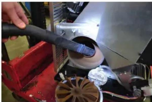
natural_image
Close-up of a hand using a black tool to clean or inspect a mechanical component, with no visible text or symbols.Number of heat levels 5
Filling volume of pellet container 15 kg
Pellet usage (min. - max.)....approx. 0.4 - 2.1 kg/h
Fuel
Connection....230 V \~ 50 Hz
Power consumption in the ignition phase....280 W
Power consumption during operation....100 W
Double use chimney....no
Flue pipe connection....rear
ø-Flue pipe outlet....80 mm
Chimney flue 10 - 12 Pa (0.1 - 0.12 mbar)
Flue gas temperature....52.3 - 154.2 °C
Flue gas mass flow 2.7 - 7.8 g/s
Construction dimensions (WxDxH) 460x450x1000 mm
Weight net/gross....77 kg / 99 kg
Wood pellets i


General warnings and safety instructions
Please always observe the introductory general warnings and read the entire manual carefully before commissioning the furnace.
The GP 100 pellet furnace has been constructed using the latest technology and recognised safety and technical regulations. However, improper or non-intended use may lead to danger. Therefore, never leave the pellet furnace unattended for longer periods of time. Only approved transport aids with sufficient load carrying capacity may be used to transport your heating device. The combustion of fuel releases thermal energy, which leads to significant heating of the surface of the heating device, the doors, the door and operating handles, the door glass, the flue pipe and, if applicable, the front wall of the heating device. Touching these parts without appropriate protective clothing or aids, e.g. heat protection gloves or operation tools (operating handle), must be prohibited.
Make your children aware of this particular danger and keep children away from the heating device during operation.
Do not place items that are not heatproof on or near the heating device.
Do not place any laundry on the furnace for drying. Stands for drying clothing or similar must be placed at a sufficient distance away from the heating device
Fire hazard
It is prohibited to process flammable and explosive substances in the same or adjacent areas when operating your heating device.
Qualification
Apart from a detailed instruction by a competent person, no special qualification for using the machine is required.
Important notes
Carefully read the instructions and technical information in these Assembly Instructions before assembly, before commencing heating and any other activities.
Carefully observing the Assembly Instructions ensures the safety of individuals and the product, as well as the cost-effectiveness and long service life of the product.
The manufacturer shall not be liable for damages that arise as a result of failure to observe the Operating and Maintenance Instructions, unauthorised changes to the product and the use of replacement parts that are not originals.
The product must be set up and operated in accordance with the manufacturer's instructions and the local provisions.
Should you experience any difficulties in understanding the written version of the Operating Instructions, please contact your retailer.
The wall behind the device must not be made of wood or a combustible material. Otherwise, the
safety distances must be observed (see section "Prevention of domestic fires" in the furnace Operating and Maintenance Instructions).
Before assembling the furnace, read the Assembly Instructions carefully with regard to cladding, fans and any accessories.
Ensure the floor is entirely even before assembling the product.
We recommend that you use clean cotton gloves when touching the steel parts in order to avoid fingerprints that are difficult to remove at a later stage.
Two people are required to assemble the furnace.
Only once connected properly to the fireplace can the pellet furnace be connected to the power supply.
Never use liquid fuel to commission the pellet furnace and/or reinvigorate the existing heat.
CAUTION
The pellet furnace may only be operated with standard wood pellets
. Operating the furnace with poor quality or non-standard pellets may lead to operational errors that are no longer covered by the warranty.
The combustion chamber door may not be opened during operation.
Sufficient air supply must be ensured in the installation space during operation.
The fuel supply is suspended in the event of an operational error. Commissioning may only be carried out once the source of error has been remedied.
Suspend operation in the event the product is damaged or faulty.
The protection guard in the pellet container must not be removed. (Fig. Page 12)
Do not place items that are not heatproof on the furnace or within the defined minimum distances of the furnace.
Ensure that third parties are made aware of these dangers!
Ensure that third parties are made aware of the safety measures that need to be observed during furnace operation.
Please observe national and European standards, as well as local provisions that apply to the installation and operation of the fireplace!
Standards cited
DIN 18160
Domestic chimneys - requirements, planning and design
DIN 51731
Testing of solid fuels - compressed untreated wood - requirements and testing
DIN 18894
Fireplaces fired by solid fuel - Pellet heaters - Requirements, testing and marking
ÖNORM M7135
Austrian standard - pellets and briquettes
Fuel
The pellet furnace is designed for clean and extremely efficient combustion of standard wood pellets with a diameter of 6 mm.
Even when using standard wood pellets, there can be some variation in combustion, ash production and slag formation.
General information about fuel
By choosing wood as a fuel, you have chosen a carbon-neutral method of heating your home. The compression of waste wood into standard pellets allows a cost-effective fuel to be produced from natural wood waste, which is converted into thermal energy in a clean and extremely efficient manner during combustion.
What are wood pellets?
Wood pellets consist of 100 per cent natural wood waste (wood shavings, sawdust etc.).
The dried waste wood is shredded and pressed into wood pellets under high pressure. The addition of binding agents or additives is not permitted.
DIN 51731 and ÖNORMM7135 set out the quality requirements for wood pellets:
Length: approx. 10 - 30 mm
Diameter: 6 mm
Bulk weight: approx. 650 kg/m3
Heat value: approx. 4.9 kWh/kg
Residual moisture: approx. < 10 %
Ash content: < 1.5 %
Density: >1.0 kg/dm3
Wood pellets in practice:
2 kg wood pellets have approximately the same energy content as one litre of light heating oil.
From a space point of view, 3 m of wood pellets correspond to
approx. 1000 litres of heating oil. Wood pellets must be transported and stored absolutely dry.
They expand significantly when exposed to moisture. This is why wood pellets must be protected against moisture during transport and storage.
How do you identify "good" wood pellets?
There can be differences in the quality of wood pellets depending on the preparation of the raw materials and the pressing of the mass.
The quality features set out below provide the information needed for an initial visual assessment of
wood pellets when purchasing. The exact quality features can only be established using suitable technical analysis devices.
Good quality:
glossy, smooth, consistent length, little dust
Lower quality:
Splits lengthways and horizontally, lots of dust, different lengths.
Simple quality test:
Place a few wood pellets into a glass of water:
Good quality: Pellets sink.
Lower quality: Pellets float.
Pellets vary in terms of colour, length and pressing process depending on the manufacturer. Different batches provided by the same manufacturer may also be of differing quality. Pellets are made from natural wood. Depending on the type of wood, the combustion residues may be higher.
Important notes before installation
When unpacking, ensure that the product is not damaged or scratched. Remove the packaged accessories from the combustion chamber and remove any foam parts or cardboard used to secure moving parts.
Please ensure that you do not store the packaging (plastic bags, foam parts etc.) within the reach of children as packaging is a potential source of danger and must be disposed of in accordance with the provisions.
Please take note of the following in order to prevent accidents and damage to the product:
At least two people are required to carry out the unpacking and installation processes;
Each work step must be carried out using suitable aids in accordance with the valid safety guidelines;
Align the packaged furnace in accordance with the images and notes in the Operating Instructions;
If aids, such as ropes, straps, chains etc. are used, these must be in orderly condition and be suitable for the weight in question;
Take care when unpacking the product and ensure that ropes, chains etc. do not break;
Do not tilt the packaging too much in order to prevent the item from tipping over;
Never stand in the field of action of the loading/unloading devices (lift truck, cranes etc.).
Flue gas connection
The device is not suitable for multiple use of chimneys!
The chimney must be measured according to EN 13384 and it must be ensured that there is negative pressure (greater than 1 Pa). Due to the type of pellet fireplace, this is not a burner but a furnace that is fed automatically with a daily container for the combustion of solid biomass (pellets) with a flue gas fan.
This fan transports the flue gases into the fireplace. No excess pressure is created in the connector and in the chimney. Regional provisions must always be observed.
Before connecting the device, please contact your local expert chimney sweep!
It is not permitted to connect the device to a chimney less than 4 m high.
The connector must be connected tightly to the chimney.
Fireplace connectors must remain at least 40 cm away from components made from combustible materials. A distance of at least 10 cm is sufficient if the connectors have a coating of at least 2 cm thickness made from non-combustible insulating materials. Connections to fireplaces must, insofar as they transport gas through components made of combustible materials, be fitted with a protective pipe made from non-combustible components at a distance of at least 20 cm or be covered with non-combustible components with low thermal conductivity at a distance of at least 20 cm.
A draft limiter is recommended for conveying pressures > 20 Pa. The conveying pressure must be at least 11 Pa.
Provisions
For installation and flue side connection, the requirements of the Firing Directive (Feuerungsverordnung), of the respective state building regulations (Länderbauordnung), as well as DIN 4705 and DIN 18160, must be observed. In order to enable your furnace to function properly the chimney to which you wish to connect the device must be in perfect condition.
Installation area
As the fireplace takes the air it requires for combustion from the installation area, it should be ensured that there is always sufficient air supply via windows and external doors that are not sealed. In addition, it must be ensured that a space performance ratio of 4 m3 per kW rated heat output is ensured. If the volume is lower, a combustion air connection must be created with other rooms via ventilation openings. (Connection openings at least 150 cm2)
CAUTION: The pellet furnace works differently to traditional furnaces. The smoke is removed using a ventilator. A low negative pressure is created in the combustion area and excess pressure is created in the connector; therefore, please ensure that this pipe is entirely sealed and has been assembled correctly both from a safety point of view and a functional point of view.
The flue pipe must be installed by experts or specialist companies.
The system must be installed so that it can be cleaned regularly without anything having to be disassembled.
The pipes must always be sealed with silicone (not with cement) as this material is heat proof and retains its elasticity even at high temperatures (250 °C). They are secured using 3.9 mm self-tapping screws.
a. Neither flaps nor doors may be installed that might interfere with the outlet of gases
b. The device must be connected as described on Page 8.
The pipes and maximum lengths of the pipes
You can use pipes made of painted steel (at least 1.5 mm thick), stainless steel or enamelled steel (at least 0.5 mm thick) with a diameter of 100 mm.
Outside air supply
The furnace must have sufficient air in order to be enable to ensure it functions correctly. This air is provided via an air supply which is located outside the space in which the furnace is installed. An outside air supply may only be installed in consultation with the chimney sweep.
• The air inlet must be directly connected to the outside
, whereby metal pipes
(at least 80 mm) with the correct
silicone seals are to be used, which ensure a good seal.
• The air supply may also come from an adjoining room in which the furnace is
located, under the condition that this
uses openings that cannot be closed and are connected to the outside
- In the room next to the one in which the furnace is installed there cannot be any under pressure with regard to
outside as the result of a cross-draught
caused by a further extraction system
(extractor fan, tumble dryer etc.) that is installed there. In this
adjacent room, the permanent openings must
meet the criteria set out above.
This room may not be used as a garage or to store combustible materials and it may not be used to carry out any activities associated with fire hazards.
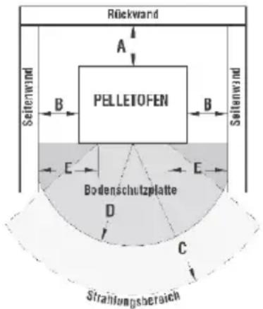
Minimum safety distances
Minimum safety distances to combustible or temperature-sensitive materials, as well as load-bearing walls < 10 cm:
A 40 cm to the rear wall
B 40 cm to the side walls
C 80 cm in the radiation area
If combustible or temperature-sensitive flooring is used, flooring protection (e.g. sheet steel), marble or tiles are to be used.
The minimum dimensions are:
D 50 cm
E 30 cm (from inner edge of furnace space opening).
A side distance of 60 cm is recommended in order to ensure that the possibility of inspecting and maintaining components in the fireplace is not impaired.
Prevention of domestic fires
The furnace must be installed and operated in accordance with the manufacturer's requirements and the local provisions.
CAUTION: If a pipe travels through a wall or ceiling, there are some special requirements to take into account for installation (insulation, protective equipment, sufficient distance from heat-sensitive materials etc.)
- The fireplace connection pipe must never pass through combustible material or flammable surfaces.
- The fireplace connection pipe may not be connected to a
flue pipe that is also linked to other devices
- It is recommended to keep all combustible or flammable objects, such as wooden
beams, wooden furniture, curtains,
flammable liquids etc. at a safe distance
(at least one metre) from the
thermal radiation and from the furnace
- Should there be any wooden ceilings nearby or other coverings made from com
bustible or heat-sensitive materials,
then a protective coating made from
insulating, non-combustible material must be affixed.
If the flooring is made from combustible material (wooden floorboards, parquet), a protective sheet made from non-combustible materials
must be affixed at the height of the furnace door that extends at least 30 cm to the side
and at least 50 cm to the front.
More information can be found in the local provisions. Under no circumstances may the combustion chamber be opened during operation!

The required setup for the fireplace, including the flue pipe, must be strictly observed. Pellet furnaces and flue pipes in accordance with our connection and setup plans form the fireplace unit.
Actions in the event of chimney
fires
Cause of the fire
There are many factors that can lead to an uncontrolled chimney fire:
- Strong wind can ignite the burning material too much, meaning that the flames reach higher than usual.
- Burning material that is not suitable or not intended for the fireplace. - Long-flame burning material (e.g. softwood) ignites the fire. - Lack of oxygen. As a result of incomplete combustion, the fuel in the combustion chamber may not be fully burnt. Afterburning then takes place in the fireplace.
Firefighting
A chimney fire must not be extinguished using water as this would immediately create water vapour inside (water vaporises at a ratio of 1:1700 at 100 °C), which would seriously damage the chimney as a result of the sudden increase in pressure and may even lead to the chimney exploding.
The firefighting options are:
- Allow the chimney to burn out in a controlled manner, i.e. being monitored all the time, whereby you can regulate the air conditions to some extent via the fireplace doors or furnace.
Use chimney sweeping tools to remove the burn - ing soot from the chimney (knock out) and extinguish outside.
- If the fire looks as if it may spread (house fire), a powder extinguisher can also be used as the final option. The fire can also be extinguished using sulphur (smothered).
- In all cases, the fire service and the local district chimney sweep experts must be contacted.
- Even once the fire has been extinguished, the fireplace must be observed for several hours as it can still give off a lot of heat.
Setup/connection
Power connection - Page 5
The furnace is delivered with a network cable for a power connection of 230 V 50 Hz.
The connection on the reverse side of the furnace is shown on Page 5.
The power consumption is detailed in the "TECHNICAL INFORMATION" chapter in these Operating Instructions.
Please ensure that the power cable has been laid correctly and does not come into contact with hot parts.
Make sure that the plug for the power cable is still accessible once the furnace has been installed.
The device must be connected as described on Page 5.
Caution! The aforementioned setup for the fireplace, including the flue pipe, must be strictly observed. Pellet furnaces and flue pipes in accordance with our connection and setup plans form the fireplace unit.
Operation
The openings that are located on the cover panel prevent the furnace from overheating and must not be closed under any circumstances. Sufficient air supply must be ensured in the installation space during operation of the furnace.
Combustion air
All combustion processes require oxygen and air, which is generally taken from the living space in the case of individual furnaces. The air that is taken must be returned to the living space. In the case of modern apartments, very tightly sealed windows and doors can mean that too little air is returned to the space. This can make the situation problematic if additional extraction systems are used in the apartment (e.g. in the kitchen or bathroom). If you cannot supply external combustion air, then you must ventilate the space several times a day in order to prevent underpressure in the space or poor combustion.
All seals in the flue system must be hermetically sealed with heatproof (250 °C) furnace putty (not cement). Regularly check the cleaning of the flue system or have this checked.
During furnace operation, do not place any combustible objects near to the furnace (minimum distance of 100 cm from the front of the furnace).
The combustion chamber door must not be opened during operation and the panel must not be damaged or missing.
Only pellets may be used as fuel.
It is strictly forbidden to remove the protection guard from the pellet container.
Remove any waste pellets that did not combust before starting heating again.
Check whether the furnace grid is fitted correctly. Fill the pellet tank (Page 12).
Close the fire door and the pellet tank flap and turn on the furnace using the main switch.
CAUTION!
When firing up the furnace for the first time and after longer periods of non-use, the furnace may only be operated at a maximum of Level 3. When firing up the furnace for the first time, a temperature that is too high may damage the insulation. You may operate the furnace as normal after approx. 2 hours
Control panel

Function button
1) "SET" button: Select function. Allows certain parameters to be programmed and the values that have been set to be saved.
2) "AUTO" button: switches the furnace from manual operation to automatic mode.
3) "ON/OFF" button: Turning the furnace on and off in manual operation. Leave programming without any changes.
Also used to stop the acoustic error signal
4) Temp+ button: increase desired temperature and move around the menu.
5) Temp- button: decrease desired temperature and move around the menu.
6) Increase heat output or set desired programmes and move around the menu.
7) Decrease heat output or set desired programmes and move around the menu.
Display details
Alarm warning
- No ignition
- Pellet tank empty
• Pressure monitor
• Power outage
• Flue ventilator defective
• Empty combustion pot
Operation
| Description | Display |
| On | Ignition in process |
| Heating | Heat |
| Manual operation | Manual |
| Automatic operation | Auto |
| Cooling | Cooling phase |
| Timing control | Set date and time |
| Weekly planner | Weekly programme |
| Select thermostat mode ^(1) | Thermostat mode |
| Internal thermostat | Internal temp. |
| External thermostat ^(1) | Exterior temp. |
| Pellet feed rate 8 ^(2) | Pellets |
| Rotation speed flue motor ^(2) | Flue ventilator |
| Rotation speed flue ventilator ^(2) | Room ventilator |
| Programme Thermostat / GSM programme ^(1) GSM performance | CRO/GSM performance |
| Pellet type | Pellet type adaptation |
| Parameters | Parameters |
| Error memory | Error memory |
| Select a language | Language selection |
(1) Not possible for GP 100
(2) We recommend not changing the default setting.
Remote control

The device can also be used with an IR remote control. Some functions can be controlled using the remote control, such as the on/off function. Before use, you need to save the remote control code. This is carried out directly on the control panel.
Saving the code
Hold down the buttons "PROG+" and "TEMP+" for 5 seconds until the display IR REMOTE CONTROL appears on the display. Point the remote control at the control panel and press a button. Once the code has been saved, an acoustic signal will sound. Leave the menu using the STOP button (3) and operate the furnace using the remote control.
Power off
You switch the furnace off by pressing the 3 button on the control panel (3 secs).
The ventilators continue to operate until the furnace has reached a safe power-off temperature. The power supply may not be interrupted during this time!
Power outage
The furnace automatically turns off if there is a power outage and does not turn on automatically again once there is voltage again.
Should this be the case, wait until the furnace has cooled down fully, clean the grate, delete the error and restart the furnace.
Commissioning
After the pellet furnace has been set up and signed off by the relevant local chimney sweep expert, the furnace can be connected to the power grid (230 V). Turn the main switch to "I" (ON) (see Page 5).
The electronic control now reports that it is ready for operation.
The backlight on the display turns on.
The points set out here explain the initial commissioning of the GP 100 pellet furnace.
1. Combustion chamber and combustion grate control
- Ensure the combustion grate is positioned correctly
2. Time/date
Pressing SET allows you to set the date. You can set the day of the week, Monday to Sunday, the time and the date.
Use the PROG+ and PROG- buttons to show the options and the TEMP+ and TEMP- buttons to select the option you wish to use. The setting is confirmed by pressing the SET button.
3. Manual/auto
The furnace can be operated manually or automatically. In manual mode, you have to switch the furnace on and off yourself. You can use the weekly programmer or timer to select the desired times in the automatic settings. Press the "Auto" button (control panel button 2) to select the desired function, which is then shown on the display.
Manual:
Switch the furnace on and off using the ON and OFF buttons.
Auto (timer/weekly programme):
The furnace automatically turns itself on and off
at the times set in the weekly programmer and the timer
In order to prevent any damage to the furnace, you can only operate it at a maximum of Level 3 for 1 hour when it is operated for the first time. Select manual mode for this.
4. Fill the pellet container
- Fill the pellet container with the correct DIN pellets.
- The protection guard in the pellet container must not be removed.

natural_image
Interior view of a black industrial machine with transparent glass panels and control buttons (no visible text or symbols)Ensure that you always close the lid on this after filling.
5. Initial loading
Caution: When you first operate the furnace, the screw conveyor for transporting the pellets has not yet been filled, which is why this must be filled first.
- To get to the menu selection, press the 1 and 6 buttons at the same time for 6 seconds.
- Confirm the "Test Programme" by pressing 1
- Search for the menu point "Screw Motor" with button 6 or 7
- Activate the initial loading by pressing 1 and hold this button down.
The conveyor drive now turns continuously in order to fill the winding shaft. This process may take several minutes. As soon as pellets are falling evenly into the combustion grate, release the 1 button.
Caution:
The combustion grate must be emptied after successful initial loading. You must then ensure that the combustion grate is positioned correctly and the furnace door is firmly closed.
The pellet furnace is now ready for operation
6. Power on
- Turn the furnace on using the 3 button or the remote control
("ON" button combination).
The cold start programme starts automatically once the furnace has powered on.
Caution: No settings can be added during the ignition phase.
Information:
A certain amount of odour may be created when the vessel heats up for the first time. This does not indicate a defect. This stops after a short while. Please ensure the installation space is ventilated sufficiently. The paintwork does not contain any toxic fumes.
Timer/weekly programme
Press the 1 button to get to the main menu.
Search for the pellet weekly programme by pressing the 4 button and confirm by pressing 1 when you have found this.
Buttons 4+5: you can use these buttons to change the values that have been set.
Buttons 6+7: you can use these buttons to switch between the menu points that have been described. The selected menu point "flashes".

1) Programme number
You can view the different power on/off times by pressing the 1 button. You only have the option of viewing programmes F01-F15. You are at F15 and you can get back by pressing the 1 button. Start again as described above.
2) Day of the week
Option to set each day individually (Sun, Mon, Tues, Weds, Thurs, Fri, Sat) or the working days (WD) or Saturdays and Sundays (WK).
3+4) hours and minutes
You can select the desired power on and off times here.
5) Temperature
You can set the desired temperature here.
6) Heat output
You can select the heat output with which the furnace turns on here. Later in its operation, the furnace regulates the heat output itself, i.e. once it is up to temperature, it regulates the heat output itself automatically to the lowest level (P1) and, when the temperature goes down, it switches back on and turns the heat output back up again.
7) Mode
You can select whether this is the power on or off time here. ON=EIN / OFF=AUS
8) Function:
You can use this menu point to select whether the programme number is activated or No. A (deactivated).
CAUTION!
During the times when programming is ON, the furnace continues to run at the same temperature and output as when it was last switched off.
Standby function
- To get to the menu selection, press the 1 button (set) to get to the menu selection.
- Select the menu point "Change param." using the 4 button.
- Confirm this by pressing the 1 button (set)
- Use button 6 to search for the menu point "Standby function"
- The standby function appears on the display.
- Set the difference temperature using the 4 button (min. 3 °C – max. 10 °C)
- Confirm this with the 1 button (set)
- The standby function is now active.
- Leave the menu point by pressing the 3 button (on/off).
- As soon as it has reached the set desired tem-
perature and exceeded the predefined difference temperature, the furnace turns itself off. The display shows standby activated and the furnace cools down.
- If the furnace falls below the set desired temperature by the predefined difference temperature, the furnace automatically switches itself back on again and the display shows ignition in process.
- Repeat points 1-5 to deactivate the standby function.
- You then need to set the difference temperature to OFF by pressing 5 and confirm using the 1 button # (Set).
- The standby function is no longer activated and the furnace can be operated manually.
Reset error memory
After remedying a fault of any kind (error code table below), the pellet furnace must be reactivated by pressing and holding the 1 and 3 buttons for 3 seconds (this resets the error memory). Afterwards, allow the pellet furnace to cool down if necessary, clean the burner gun, ensure the burner gun is positioned correctly and restart the furnace.
Error code table
| DISPLAY DESCRIPTION OF THE FAULT | CAUSE OF THE FAULT REMEDYING THE FAULT | ||
| CODE 1NO IGNITION | No ignition is taking place | The pellet tank is emptyThere is a fault with the heater plugNo pellet transportation | Fill pellet tankReplace faulty heater plugReplace faulty screw motorRemove blockage from screw shaft |
| CODE 3ERROR IN SMOKE CIRCULATION | Insufficient air supply Fresh | air inlet is blocked Ensure that the furnace can draw in fresh air | |
| CODE 5PELLET TANK EMPTY | Turn off in operation Pellet | tank is empty 1. Fill pellet tankCarry out initial loading | |
| CODE 6PRESSURE MONITOR | Smoke outlet blockedPellet furnace over-heated | Flue pipe blockedTrigger of the safety thermostat due to over-heatingTo 2. possible faulty room ventilator | Check flue pipes and remove any blockagesLeave pellet furnace to cool down, disconnect the device from the electricity network and reset the safety thermostat as follows (turn the protective cover and press reset, see Page 5; Fig. A) |
| CODE 8POWER OUTAGE | Power outage Power outage during operation | Check mains plugCheck device fuse under the main switch (see Page 5 Fig. A)Check home fuse | |
| CODE 9FLUE VENTILATOR DEFECTIVE | Outage of the flue ventilator | Flue ventilator defective Replace flue ventilator (see cleaning plan) | |
| CODE 10OVERHEATING | Control board overheating | Overheating of the control board | Leave the pellet furnace to cool down and restart |
| CODE 11ERROR | The self-set Expiry date has been exceeded | Parameters (month and year) have been set | Reset settings |
Cleaning plan
Contents:
- Cleaning & maintenance Page 17
- Cleaning the combustion pot and support Page 17
- Cleaning the scraper Page 17
- Cleaning the ash pan Page 17
- Cleaning the glass Page 17
- Cleaning the surfaces & cladding Page 18
- Cleaning the combustion chamber Page 18
- Cleaning the fans Page 19
- Service intervals
- Flue pipes
- Cleaning at the end of the season Page 20
Page 20
Page 20
The operator must clean the device regularly in order to ensure trouble-free operation. In the event of failure to comply, all guarantee claims become invalid. All cleaning work must only be carried out when the device is switched off and has fully cooled. The device must be disconnected from the mains power supply!
Pellet ash is a natural and pure product and is suitable for use as a fertiliser for all plants in your home and garden.
Cleaning and maintenance
Please take note of the following before carrying out any maintenance and/or cleaning work:
- Ensure that all the parts of the furnace have cooled down;
- Ensure that the ash has burnt off fully;
- Ensure that the main switch is set to zero;
- Ensure that the mains plug has been removed from the socket to avoid any accidental contact;
• After you have finished the maintenance work, check that everything is in order as it was before you commenced the work, i.e. whether the combustion pot is positioned correctly.
Carefully follow the instructions detailed below for cleaning processes.
Failure to comply with the instructions may lead to operational errors.
Cleaning the combustion pot and support (daily)
If the furnace is operated on a daily basis, the combustion pot must be cleaned regularly, at the latest when the flame is weak, turns red or emits black smoke. This means that ash and accumulations have developed that prevent the furnace from being operated correctly and must be remedied (Fig. 13). The combustion pot must be cleaned every day by removing it from the furnace. Then remove the ash and any accumulations that have developed, ensuring that you remove any blockages from holes using a sharp tool (e.g. screwdriver, not included in the delivery). Cleaning is particularly important in the furnace's first operating hours, particularly if a pellet type is being used that does not correspond to the DIN Plus standard we recommend. The combustion pot support should also be checked regularly and any ash suctioned away.

natural_image
Close-up of a hand using a pipette to test a dark liquid in a container (no visible text or symbols)Fig. 13
CAUTION!
The combustion pot must be cleaned every day and the ash pan must be cleaned regularly. Insufficient cleaning of the furnace may impair the function of the furnace and damage the furnace (possible emissions of unburnt pellets and soot). Under no
circumstances may pellets that did not burn as a result of a failed ignition attempt be reused.
Ash pan (as needed)
Open the door and remove the ash pan. Use an ash vacuum cleaner to remove the ash from the ash pan. This activity may be carried out as often as made necessary by the quality of the pellets that are being used (Fig. 15).

natural_image
Close-up of a metallic industrial machine with a circular top component, mounted on a base (no visible text or symbols)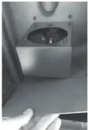
natural_image
Close-up of a metallic mechanical component with a circular opening and a hand adjusting it (no visible text or symbols)Fig. 15
Cleaning the glass
The glass is self-cleaning. Whilst the furnace is in operation, the air passes over the surface of the glass and keeps it free from ash and dirt.
However, as a result of the fine ash created by wood pellets, a coating settles on the viewing panel which may be very light or dark depending on the output level of the furnace. This is a natural process during combustion and does not constitute a fault.
- The layer of soot on the glass can be gently removed using a dry cloth.
- Stubborn dirt may only be removed using ammonia-based degreasing agents that are non-corrosive.
The viewing panel must have cooled down before cleaning. Take care not to scratch or damage the glass.
Cleaning the surfaces & cladding
Painted surfaces/metal parts:
Use a damp, soft cloth for cleaning. Under no circumstances should you use alcohol, diluting agents, acetone or degreasing substances and/or abrasive cleaners.
Surface:
Wipe gently with a damp cloth. Do not scrub. Do not use abrasive cleaning products or acidic/alkaline cleaning products.
Using aggressive cleaning and/or diluting agents causes damage to the surface of the furnace. Before you use a cleaning product, test it on an area that is not visible.
Cleaning the combustion chamber (once a month)
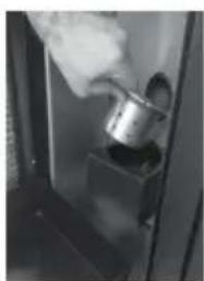
- Open the door and remove the brazier and the ash container (see Image 1).
Untwist both the screws on the partition (see Image 2). - Pull the central partition outwards and remove the flame heater, whilst supporting it at the same time. This is located at the top (see Image 3-4).
- Remove both screws and the flap (see Image 5-6).
- Take the right and left inner side of the partition and pull it outwards (see Image 7-8).
- Take the lower part and pull it up sideways (see Image 9-10).
- Clean the inner pipe using a wire brush (see Image 11-12).
- Use a vacuum cleaner to remove the ash from the combustion chamber (see Image 13) behind the tubes (see Image 14) and the inside of the brazier (see Image 15).
- Carry out the steps in reverse order during assembly.
natural_image
Close-up of a metallic object being poured into a dark container (no visible text or symbols)
natural_image
Hand holding a tool inside a stainless steel enclosure with a circular vent and a small dish (no visible text or symbols)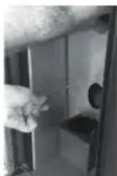
natural_image
Hand inserting a small object into a door (no visible text or symbols)natural_image
Interior view of a refrigerator with a hand inserting a dark object (no visible text or symbols)
natural_image
Close-up of hands installing or adjusting a mechanical component (no visible text or symbols)
natural_image
Close-up of a hand holding a white electronic device with a small component, no visible text or symbolsnatural_image
Close-up of a hand touching a metallic panel or fixture (no visible text or symbols)
natural_image
Interior view of a room with a hand near a door (no visible text or symbols)
natural_image
Interior view of a kitchen appliance with a double door and cloth (no visible text or symbols)natural_image
Close-up of a hand holding a flat surface with a small rectangular object in the background (no visible text or symbols)
natural_image
Close-up of a hand holding a white tool inside a vehicle or car (no visible text or symbols)
natural_image
Close-up of a hand holding a medical IV drip in a clinical setting (no visible text or symbols)
natural_image
Close-up of a mechanical component with a circular top and curved base, labeled 'Fig. 10 Fig.' (no other text or symbols visible)
natural_image
Close-up of a hand holding a small object, possibly a tool or device, with no visible text or symbols.
natural_image
Close-up of a hand pressing a button on a dark surface, with a small oval object partially visible above (no text or symbols)Fig. 13 Fig. 14 Fig. 15
Cleaning the fans (once a year or when "service" is displayed)
We recommend that you carry out this maintenance work at least once a year and twice a year for frequent use.
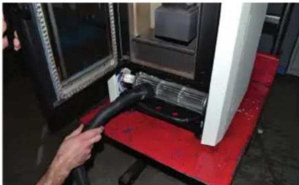
The furnace has space and flue gas fans on the reverse and underside of the furnace.
Any dust and/or ash residues on the fan blades create imbalance and noise during operation. Therefore, it is necessary to clean the fans at least once a year and/or when "service" is shown on the display.

natural_image
Close-up of a black electronic device with two red circular annotations highlighting features (no readable text or symbols)1) Remove both screws on the front panel. You can now remove the panel by lifting it at the right-hand side and then pulling it away forwards.
natural_image
Person using a black cable to connect a device on a red platform, with no visible text or symbols.2) Vacuum the fan and the flooring sheet thoroughly.

natural_image
Close-up of a mechanical component with red circles highlighting features, no visible text or symbols6) Now remove both screws on the left side section. The side section can now be lifted away upwards.
natural_image
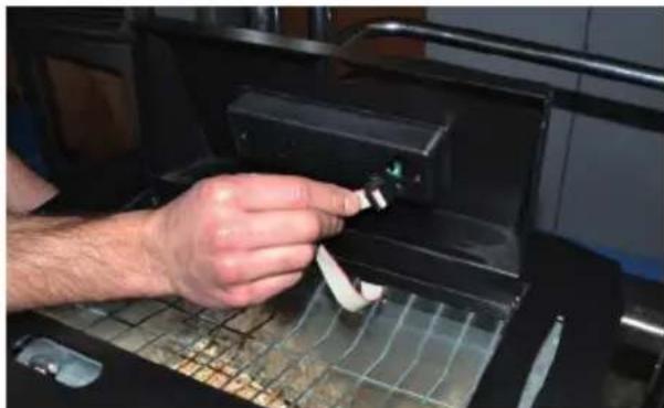
Person using a handheld device to press or install electronic components (no visible text or symbols)3) Next, open the pellet container and remove the cable from the control panel.

natural_image
Close-up of a hand holding a white rectangular object next to a red surface, with visible wiring and components (no text or symbols)6.1) During assembly, ensure that the side section is secured with both lower screws.

natural_image
Close-up of a hand inserting a small golden coin into a black plastic car hood (no text or symbols visible)4) Now remove both nuts on the lower right and/or left side.
natural_image
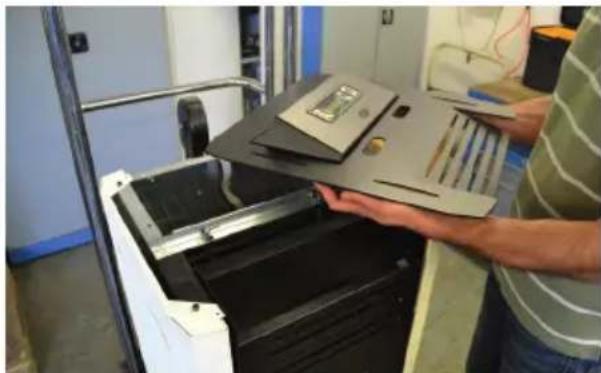
Person handling a device with a folder and notebook, no visible text or symbols5) Remove the upper part of the furnace.

natural_image
Close-up of a hand adjusting a mechanical device with visible wiring and components (no text or symbols)7) Remove the tube...

natural_image
Close-up of a mechanical device with visible wiring and components, no text or symbols present8) ... and remove the 4 screws on the cover.

natural_image
Red industrial machine with a multi-blade fan component, no visible text or symbols
natural_image
Close-up of a hand using a black cable to clean or store air in a red industrial machine (no visible text or symbols)9) The fan can now be removed and the dirt can be cleaned out of the inside using a vacuum cleaner. Only
use a brush attachment for the fan!
10) Now put the furnace back together in reverse order.
Reset "service" interval for servicing
To get to the menu selection, press the 1 and 6 buttons at the same time for 6 seconds. Confirm the "Test Programme" by pressing 1. Press the 6 or 7 button until "Hours (operating hours)/Serv (service hour counter)" appears on the display. Now press buttons 4 and 5 and hold them down for 5 seconds. The service counter has now been reset. Exit the menu by pressing 3.
Cleaning the flue pipes
Clean the flue pipes on your fireplace at least once a year
Cleaning at the end of the season
Carry out all the cleaning processes that have been described at the end of the season.
In order to empty the screw conveyor, carry out the initial loading process without adding any more pellets. The pellets still in the screw conveyor are then released.
Service
Even after you have made your purchase, our service team will be happy to help with anything you may need! You can reach us on Mondays-Fridays between 9 am and 6 pm and on Saturdays between 8 am and 12 noon. Please find our contact details below:
Phone: 07904/700-360
Fax: 07904/700-51999
Email: support@ts.guede.com
Tip: It is convenient to order spare parts via our online shop at www.guede.com
We will provide you with support: Either on-site or via our central
customer service team in Wolpertshausen.
You can find out more in our
warranty conditions.
Warranty Conditions for GP 135 pellet furnace
A) The following conditions set out the prerequisites for and the scope of our warranty service with regard to the abovementioned products. In this regard, we would point out that, regardless of this warranty, the statutory and contractual warranty claims between the vendor and the customer shall remain unaffected. B) Güde GmbH & Co. KG guarantees, under the prerequisites of these Warranty Conditions, that the pellet furnace shall remain free of any defects in terms of the materials and workmanship for a period of 24 months after the shipment of the device (from the premises of Güde).
C) Warranty services
Should the pellet furnaces exhibit any defects within this period, Güde GmbH & Co. KG shall, at its own discretion, either remedy these defects with its on-site customer service or with its central customer service in Wolpertshausen. The warranty service may be provided in the form of a repair or by a replacement delivery of the defective part.
D) Assertion of warranty claims
Güde GmbH & Co. KG / Technical Service Department / Birkichstrasse 6 /
D-74549 Wolpertshausen, Germany / Fax 07904/700-51999 / Email: support@ts.guede.com must be informed of any warranty claims without undue delay after the circumstances that form the basis for the warranty claim become known.
Customers shall only be authorised to return parts with the prior written permission of Güde GmbH & Co KG.
Claims may only be asserted provided that a receipt is presented to prove the acquisition and time and date of the acquisition.
Only the first end user shall be entitled to assert any claims.
E) Disclaimer
Normal wear and tear that is typical for use shall not constitute a fault or error within the meaning of these Warranty Conditions.
The warranty promise shall cease to be valid
- in the event of improper or careless use or in the event of transport damage
- in the event of improper repair or installation
- in the event of changes or non-expert interference with the product
- in the event of use in unsuitable environmental conditions or in the event of failure to observe the product specifications, Operating Instructions or improper maintenance
- as a result of influences such as dirt, cleaning using aggressive substances or other contamination
- in the event of damage as a result of force majeure or unforeseeable circumstances beyond the control of Güde GmbH & Co. KG.
F) The warranty shall not cover
Glass, seals, heater plug and defects that are a result of or linked to foreign bodies in the pellets or pellet tank. Furthermore, there shall be no warranty obligation in the event of minor deviations from the nominal condition that are insignificant for the value and usability of the device.
G) Other provisions
Any further or other claims beyond the scope of the warranty, in particular claims to compensation with regard to damage incurred outside the device, shall be excluded insofar as liability is not mandatory under the law.
This warranty and any legal disputes relating to this warranty shall be governed by the law of the Federal Republic of Germany to the exclusion of the UN Convention on Contracts for the International Sale of Goods (CISG) and conflict of laws provisions.
Natural products, such as natural stone, are subject to fluctuation in terms of colour, structure and inclusions. For this reason, deviations shall not constitute reason for any complaints (DIN 18332, VOB Part C).
Marks (cracks in the surface) are specific to the material and therefore shall not constitute reason for any complaints.
Technische gegevens
Pelletkachel..... GP 135
Weekplanner Weekprogramma
Thermostaatmodus kiezen ^(1) Thermostaatmodus
Interne thermostaat Binnentemp.
Externe thermostaat ^(1) Buitentemp.
Transporthoevl. pellet 8 ^(2) Pellets
natural_image
Interior view of a modern office or gas station with glass partitions and overhead equipment (no visible text or symbols)natural_image
Close-up of a hand using a pipette to test a dark liquid in a container (no visible text or symbols)Afb. 13
LET OP!
natural_image
Close-up of a metallic industrial machine with a central circular component and a handle, mounted on a flat base (no visible text or symbols)
natural_image
Close-up of a metallic mechanical component with a central housing and a hand adjusting it (no visible text or symbols)Afb. 15
natural_image
Close-up of a hand holding a metallic object, possibly a container or tool, inside a dark frame (no visible text or symbols)
natural_image
Hand holding a tool interacting with a circular object inside a container (no visible text or symbols)
natural_image
Close-up of a hand opening a door lock (no visible text or symbols)natural_image
Interior view of a metal filing cabinet with a hand inserting a black folder (no visible text or symbols)
natural_image
Close-up of hands installing a cable or wire component into a device (no visible text or symbols)
natural_image
Close-up of a hand holding a white plastic component, possibly a tool or device (no visible text or symbols)natural_image
Close-up of a hand holding a white object, possibly a tool or device, with no visible text or symbols.
natural_image
Exterior view of a modern office building (no signage)
natural_image
Interior view of a kitchen appliance with a double door (no visible text or symbols)natural_image
Close-up of a hand holding a flat surface with a small rectangular object in the background (no visible text or symbols)
natural_image
Close-up of a hand holding a white tool near a vehicle door (no visible text or symbols)
natural_image
Close-up of a hand holding a medical or surgical instrument, with no visible text or symbols.natural_image
Close-up of a mechanical component with a circular opening and textured surface (no visible text or symbols)
natural_image
Close-up of a pipe with visible pipes and a circular object on a wall (no text or symbols)
natural_image
Close-up of a hand pressing down on a dark circular object with a metallic panel, no visible text or symbolsnatural_image
Close-up of a black mechanical component with two red-circled holes, no visible text or symbolsnatural_image
Person using a black cable to connect a device on a red platform, with no visible text or symbols.natural_image
Person using a handheld device to press or install electronic components on a grid-patterned surface (no visible text or symbols)natural_image
Hand placing a small golden object into a black plastic container (no visible text or symbols)natural_image
Person handling a printer or scanner device in a lab setting (no visible text or symbols)natural_image
Close-up of a metal frame with two red-circled holes, no visible text or symbolsnatural_image
Close-up of a hand holding a white rectangular object next to a 3D printer on a red surface (no visible text or symbols)natural_image
Close-up of a hand adjusting a mechanical device with visible wiring and components (no text or symbols)7) Trek de slang weg ...

natural_image
Close-up of a mechanical device with visible wiring and red circular annotations (no readable text or symbols)8) ...en maak de 4 schroeven van de afdekking los.

natural_image
Close-up of a red industrial machine with a metallic fan and mechanical components (no visible text or symbols)
natural_image
Close-up of a hand using a black tool to clean or inspect a mechanical component, with no visible text or symbols.EC-DECLARATION OF CONFORMITY
We, hereby declare the conception and construction of the below mentioned appliances correspond - at the type of construction being launched - to appropriate basic safety and hygienic requirements of EC Directives. In case of any change to the appliance not discussed with us the Declaration expires.
DECLARATION CE DE CONFORMITE
PROHLASENI O SHODE EU
2006/95/EC 2004/108/EC
2009/105/EC 1907/2006/EC
2011/65/EC ROHS 2009/142/EC
89/686/EEC (PPE) 1935/2004/EC
□ □
2006/42/EC
Annex IV
Notified Body:
Type Ex. Cert.-No.:
2000/14/EC_2005/88/EC
Noise: guaranteed L_WA dB (A)
97/6 8/EC_
Emission No.: