
IAN 49327 - Faucet Ernesto - Free user manual and instructions
Find the device manual for free IAN 49327 Ernesto in PDF.


| Product Type | Household Appliance |
| Brand | Ernesto |
| Model | IAN 49327 |
| Dimensions (W x D x H) | 30.0 x 20.0 x 15.0 cm |
| Weight | 1.2 kg |
| Power Consumption | 800 W |
| Voltage | 220-240 V ~ |
| Frequency | 50/60 Hz |
| Material | Plastic and stainless steel |
| Color | White/Silver |
| Functions | Mixing, blending, chopping |
| Speed Settings | Variable speed with pulse function |
| Capacity | 1.5 L |
| Cord Length | 1.0 m |
| Safety Features | Overheat protection, non-slip feet |
| Cleaning | Detachable parts dishwasher safe |
| Maintenance | Wipe with damp cloth |
| Accessories | Measuring cup, spatula |
| Repairability | Spare parts available online |
Frequently Asked Questions - IAN 49327 Ernesto
User questions about IAN 49327 Ernesto
0 question about this device. Answer the ones you know or ask your own.
Ask a new question about this device
Download the instructions for your Faucet in PDF format for free! Find your manual IAN 49327 - Ernesto and take your electronic device back in hand. On this page are published all the documents necessary for the use of your device. IAN 49327 by Ernesto.
USER MANUAL IAN 49327 Ernesto
natural_image
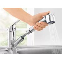
Modern kitchen sink with a metallic faucet pouring water, set against a brick wall and window (no text or symbols visible)Kitchen Mixer Tap 78570/II
GB IE
Kitchen Mixer Tap
Assembly, operating and safety instructions
SE
Engreppsblandare
copyright by Franz Joseph Schütte GmbH

GB IE
Before reading, unfold both pages containing illustrations and familiarise yourself with all functions of the device.
FI
GB /IE Assembly, operating and safety instructions Page 5
Components, fittings and fixings Page 6
Technical Data Page 6
Safety advice Page 6
Assembly
Installing the fitting...... Page 7
Flushing the tap.... Page 7
Use
Bringing into use Page 7
Water-saving function Page 8
Setting the scald protection.... Page 8
Servicing and cleaning
Maintaining and cleaning the faucet.... Page 9
Replacing the cartridge.... Page 9
Disposal Page 9
Information
Potability of mains water.... Page 9
Warranty Page 10
Service Page 10
Kitchen Mixer Tap
- Introduction
Dear Customer, you have purchased a durable high quality product manufactured by us. Before installation please read through the whole of these instructions and take note of the advice they contain before you start the installation. These instructions contain important information about installation, settings and care. Keep these instructions safe and if you pass on the product to anyone else please pass on the documentation as well.
- Proper use
This product is suitable for instantaneous water heaters (flow heaters) and boilers. It is not suitable for low pressure water heaters such as wood or coal burning bath geysers, oil or gas bath geysers, open electrically heated water tanks. Any use other than that described here or modification to the product is not permitted and may lead to damage to persons or property. There is also the risk of injury and loss of life. The product is intended for personal use only and not for medical or commercial use.
Components, fittings and fixings (Fig. A)
1 Adjusting leveré/andhe
2 Locking screw
3 Hot/cocolate
4 Cambridge ever ring
5 Cambridge securing ring
6 Adjusting ring
7 Cartridge
8 Casing cylinder
9 Sealing rings
10 Tap body
10a Hole marked red / hot water connection
10b Hole marked blue / cold water connection
11 Plastic cylinder
12 Body of the tap
13 Threaded ring
14 Seal
15 Crescent-shaped seal
16 Crescent-shaped metal disc
17 Threaded rod
18 Nut
19 Red fibre gasket
20 Connecting part
21 Connecting pipes
22 Spray head
22a Spray selector ON
22b Spray selector OFF
23 Mixing nozzle
24 Seal
25 Nylon sprinkler has
26 Seal
27 Counterweight
28 Screws
29 Allen key yffodetaching the locking screw 2)
30 Lever ararm
31 Adjustment screw
Technical Data
Connections: ^3/_8 " IG
Union nut for the
water connection: 19 mm
Water temperature: max. 85 °C
Water pressure: min.: 0.5 bar,
max.: 3 bar

Safety advice

DANGER OF LOSS OF LIFE AND ACCIDENT TO INFANTS AND CHILDREN! Never leave
children unsupervised with the packaging materials. Danger of suffocation.
CAUTION! DANGER OF INJURY! Please ensure that no parts are damaged and that all parts are correctly assembled. Incorrect assembly or fitting may lead to injury. Damaged parts can adversely affect safety and proper function.
CAUTION - RISK OF DAMAGE! Please have the installation done by experienced persons only.
■ Ensure that all seals are correctly seated.
■ DANGER OF SCALDING! When making the hot water setting please ensure that the temperature of the water is not too high.
- Please note that seals are wear parts and therefore will require to be replaced from time to time.

BEWARE OF ELECTRIC SHOCK!
Leaks can put your life at risk from electric shocks. Carefully check that all connections are watertight. Also ensure that all wires of electric appliances are correct and have been securely installed.
■ Any leakage or sudden escape of water can cause considerable damage to buildings and property. All connections must therefore be checked carefully to ensure that they are tight.
- Familiarise yourself prior to installation with all local conditions, e.g. water connections and shut-off device.
- Assembly
- Installing the fitting
- Shut off the main water supply, Allow the remaining watertborumoff.
- Place the gasket 14 into the groove on the lower side of the threaded ring 13.
- Using your hands, screw the two flexible hoses 21 into their designated holes 10a and 10b on the lower side of the tap (Fig. B). Both hoses are identical and suitable for warm and cold water.
- Screw the threaded pole 17 with the side on which the gasket it into the middle hole on the lower side of the tap. Push the flexible hoses 21 and the threaded rod 17 through the opening in the sink.
- Put the half-moon gasket 15 and the half-moon metal disc 16 onto the threaded rod 17 (Fig. C).
- Screw on the screw nut 18 so that the, so mixer tap is attached to the sink unit. Please pay attention to the pivoting range of the tap that you require.
-
Screw the connector20 onto the threaded rod
-
Place the red fibre gasket 19 in between.
-
Screw the nylon sprinkler hose 25 onto the connecting part 20 (Fig. D). Place the seal 26 in between.
- Attach the counterweight 27 to the mixer hose 25 using the screws 28.
- The distance between the counterweight 27 and the sink unit should be approx. 40 cm.
- Connect the flexible hose ^21 to the water supply.
CAUTION:
Do not twist the hoses or place them under tension.
☐ Check all connections carefully after first-time installation to make sure that they are tight. In the event of incorrect installation, all warranty claims - particularly in relation to subsequent damage - are excluded.
- Flushing the tap
In order to remove any possible impurities, the tap has to be flushed before it is used for the first time (Fig. E). Proceed as follows:
Note: Cover the parts that have to be screwed with a damp cloth or with plastic clamps. This prevents them from getting scratched.
- Unscrew the mixing nozzle 23.
- Open the mains water supply and let the water run for two minutes.
- Screw the mixing nozzle 23 back onto the rinser 22.
Use
- Bringing into use
Note: If the tap has not been used for a long period flush the pipes through thoroughly in order to avoid stagnation and build-up of residues.
- Open the main water supply.
-
Lift the handle 1 and swing it to the right or left in order to regulate the speed or temperature of the water.
-
Press the spray selector ON ^22a on the underside of the spray head 22 in order to change from the water jet to the spray jet. This function is useful when washing vegetables and fruits as they may be damaged by a normal water jet. Press the spray selector OFF 22b on the underside of the spray head 22 in order to return to the normal water jet.
Hot water: swing the handle 1 to the left. Cold water: swing the handle 1 to the right.
☐ Check operation of the mixer. To do so, swing the lever 1 into all permissible positions. Please check the connections regularly to ensure that they are tight.
● Water-saving function
The fitting has a water-saving function. This feature limits the rate of water flow through the fitting. The flow can be infinitely regulated between 0 - 100 % by means of a stop.
□ Turn off the water supply.
Remove the red/blue hot/cold label by moving the lever 1 to the highest setting and from the inside with a long flat object carefully push the label out.
☐ Release the lock screw by turning it anticlockwise using the Allen key 29.
CAUTION! Do not take the screw completely out; just loosen it until the lever 1 can be easily taken off.
Take diff'laylever.
Note: see setting screw for regulating the water flow is in the lever arm 30, which projects from the cartridge (Fig. G).
☐ To reduce the flow, turn the setting screw clockwise. This limits the movement of the lever arm 30 and therefore the lever 1. The flow is reduced as the lever 1 now cannot be lifted quite so high.
Note: The more you turn the screw clockwise, the more the flow is reduced.
Place the lever back on to the lever arm 30 and tighten the lock screw 2 by turning it
clockwise using the Allen key 29.
☐ Press the red/blue hot/cold label into the opening.
☐ Turn on the water supply.
- Setting the scald protection (Fig. F)
The cartridge 7 in this faucet has a scald protection function. This function is not activated before leaving the factory (neutral setting).
CAUTION! Do not alter the setting of the scald protection until you have installed the faucet.
□ Switch off the great water supply.
- Remove the red/blue hot/cold plate 3 by moving the handle i into top-most position and pushing the plate out carefully from inside with a long, flat object.
- Reassell the locking screw 2 with the Allen key 29 by turning it in an anticlockwise direction. CAPTAUTION! You should not remove the screw completely, but simply loosen it until the handle 1 can be easily removed.
- Remove the handle 1.
- Unscrew the cartridge end ring 4. Now pull the red adjusting ring 6 upwards. Note: Press the cartridge pins slightly backwards. This makes it easier to pull up the adjusting ring 6. Do not use pliers. Do not release the cartridge nut and do not take off the cartridge 7.
- Reducing the hot water flow rate: Replace the adjusting ring 6 as shown in Figure F / 1 in offset position.
Restricting the hot water flow rate completely: Install the adjusting ring 6 as shown in Figure F / 2.
Deactivating the hot water flow rate limitation: Install the adjusting ring 6 as shown in Figure F/3, neutral position.
- After setting the scald protection device, replace the cartridge cover ring 4 and the handle 1.
● Servicing and cleaning
- Maintaining and cleaning the faucet
Please note that sanitary fittings require special care. Please observe the following instructions:
Dry your taps with a cloth after every use in order to avoid the build-up of any limescale.
□ Clean your fittings with clean water, mild detergent and a soft cloth or leather only.
☐ Do not use any agents to remove limescale, acidic cleaning agents or scouring agents of any kind. Do not use corrosive or alcohol-containing agents for cleaning (including for coloured surfaces).
□ Dry your taps with a cloth after every use in order to avoid the build-up of any limescale.
☐ Unscrew the mixing nozzle 23 at regular intervals and remove any limescale deposits or foreign bodies. If it is very dirty or damaged, replace the mixing nozzle 23 with a new one, which you can order through the service centre indicated.
Note: The mixing nozzle 23 can normally be unscrewed by hand. Otherwise you can use a 23 mm wrench and you must lay a thin, damp cloth around the mixing nozzle 23 so that you do not damage it. A pipe wrench with plastic jaws is also suitable. In any event, make sure that you do not damage the mixing nozzle 23.
If the care and maintenance instructions are not followed, damage to the surface of the fitting can be expected. Claims under the warranty are excluded in this case.
- Replacing the cartridge
A cartridge 7 is a wear part that needs replacing according to the hardness and / or degree of contamination of the water. This becomes evident when the handle 1 becomes difficult to move.
New cartridges can be obtained from the listed service office.
Proceed as follows to replace the cartridge 7:
- Shut the main water supply off. Allow the remaining water to run off.
- Remove the hot/cold plate 3 and unscrew the locking screw 2 with the Allen key 29 in an anticlockwise direction.
- Pull the handle 1 upwards and off.
- Unscrew the cartridge cover ring 4.
- Release the cartridge securing ring 5 beneath it and pull the complete cartridge 7 out of the body of the faucet.
- Place the new cartridge into the body of the faucet in exactly the same way. Makesure that the seal is fitted properly under the cartridge. Make sure that the guides are in the corresponding holes.
- Replace all aforementioned parts. Tighten the cartridge securing ring 5 hand-tight whilst holding the faucet in place against the rotating movement. This ensures tightness and prevents the lever motion from becoming sluggish.
Disposal
To protect it from any damage in transit, this product is delivered in secure packaging. The packaging consists of recyclable materials. Please dispose of them in an environmentally friendly way.
Do not throw the product away with normal domestic waste at the end of its useful life; instead, please contact your local authority to find out how you can dispose of items in an environmentally friendly way.
- Information
- Potability of mains water
☐ Find out about the potability of your mains water supply. Your local water authority or water supply company will be able to inform you.
The following general recommendations apply to the potability of the water from your pipework:
- Let the water run freely for a short time if it has been stagnating in the pipework for more than four hours. Do not use any of this stagnant water in the preparation of food or for drinking. This applies particularly as far as babies and infants are concerned. Failure to observe this advice may result in risks to health. Fresh water can be readily distinguished from stagnant as fresh water is noticeably cooler.
- Do not use stagnant water from chromium-plated pipework for the preparation of food or for drinking or for personal hygiene if you are allergic to nickel. This water may contain high quantities of nickel and trigger an allergic reaction.
- Do not use water from lead pipework for preparing food or drink for babies or infants. Do not use it for preparing food or drink during pregnancy. Lead dissolves in drinking water and is particularly damaging to the health of babies and young children.
Warranty
This product underwent strict quality control during manufacture. Therefore we provide a 3-year warranty covering material and manufacturing defects that detrimentally affect the proper operation and intended use of the product! Detrimental effects on functions caused by limescale deposits are excluded from the warranty, as is damage caused by incorrect installation or chemical or mechanical action (e.g. through the use of unsuitable cleaning materials or improper handling).
This warranty card is only valid in conjunction with the purchase receipt for the product.
Service
Should you have reason to claim under the warranty please contact:
Service Centre details:
49134 Wallenhorst (Germany)
info@fjschuette.de
www.fjschuette.de
We are here to help you should you have any further questions.
We hope you enjoy using your mew kitchen mixer tap.
Johdanto
flowchart
graph TD
    A["Tool Tip"] --> B["Assembly Step"]
    B --> C["Reaction Valve with 2 min mark"]
    C --> D["Assembly Point"]
    D --> E["Final wrench and wrench"]

flowchart
graph TD
    A["Step 1"] --> B["Step 2"]
    B --> C["Step 3"]
    C --> D["+/-"]
    style A fill:#f9f,stroke:#333
    style B fill:#f9f,stroke:#333
    style C fill:#f9f,stroke:#333
    style D fill:#f9f,stroke:#333


IAN 49327
© by ORFGEN Marketing
Last Information Update · Tietojen tila
Informationsstatus · Tilstand af information
natural_image
Abstract geometric shape composed of two connected L-shapes in maroon and white (no text or symbols)
- Kitchen Mixer Tap 78570/II
- Safety advice Page 6
- Assembly
- Use
- Servicing and cleaning
- Disposal Page 9
- Information
- Kitchen Mixer Tap
- - Introduction
- - Proper use
- Components, fittings and fixings (Fig. A)
- Technical Data
- Safety advice
- BEWARE OF ELECTRIC SHOCK!
- - Assembly
- - Installing the fitting
- CAUTION:
- - Flushing the tap
- - Bringing into use
- ● Water-saving function
- - Setting the scald protection (Fig. F)
- ● Servicing and cleaning
- - Maintaining and cleaning the faucet
- - Replacing the cartridge
- Disposal
- - Information
- - Potability of mains water
- The following general recommendations apply to the potability of the water from your pipework:
- Warranty
- Service
- Service Centre details:
- Johdanto
Brand : Ernesto
Model : IAN 49327
Category : Faucet