
FZ 214 W - Wine cellar VESTFROST - Free user manual and instructions
Find the device manual for free FZ 214 W VESTFROST in PDF.

User questions about FZ 214 W VESTFROST
0 question about this device. Answer the ones you know or ask your own.
Ask a new question about this device
Download the instructions for your Wine cellar in PDF format for free! Find your manual FZ 214 W - VESTFROST and take your electronic device back in hand. On this page are published all the documents necessary for the use of your device. FZ 214 W by VESTFROST.
USER MANUAL FZ 214 W VESTFROST
natural_image
Exterior view of a stainless steel refrigerator with clear glass doors (no visible text or symbols)
FZ 214 W
GB Instructions for use
As the appliance contains a flammable refrigerant, it is essential to ensure that the refrigerant pipes are not damaged.
The quantity and type of the refrigerant used in your appliance is indicated on the rating plate.
Standard EN378 specifies that the room in which you install your appliance must have a volume of 1 m^3 per 8 g of hydrocarbon refrigerant used in the appliances. This is to avoid the formation of flammable gas/air mixtures in the room where the appliance is located in the event of a leak in the refrigerant circuit.
WARNING:
Keep ventilation openings in the appliance's cabinet or in the built-in structure clear of obstruction
WARNING:
Do not use other mechanical devices or other means to accelerate the defrosting process than those recommended by the manufacturer
WARNING:
Do not damage the refrigerant system
WARNING:
Do not use electrical appliances inside the refrigerated storage compartment, unless they are of a type recommended by the manufacturer
WARNING:
Do not expose the appliance to rain
WARNING:
This appliance is not intended for use by children and above and persons with reduced physical, sensory or mental capabilities or lack of experience and knowledge if they have been given supervision or instruction concerning use of the appliance in a safe way and understand the hazards involved
WARNING:
Do not store explosives, such as aerosol cans with flammable propellants in the unit.
WARNING:
Cleaning and user maintenance shall not be made by children without supervision
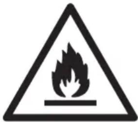
natural_image
Warning symbol of a flame inside a triangle (no text or numbers)• Always keep the keys in a separate place and out of reach of children
- Before servicing or cleaning the appliance, unplug the appliance from the mains or disconnect the electrical power supply
- If the supply cord is damaged, it must be replaced by the manufacturer, its service agent, or similarly qualified persons in order to avoid a hazard
- Relevant for Australia: Supply cord fitted with a plug complies with AS/NZS 3112.
- Frost formation on the interior evaporator wall and upper parts is a natural phenomenon. Therefore, the appliance should be defrosted during
normal cleaning or maintenance.
- Please note that changes to the appliance construction will cancel all warranty and product liability
- This appliance is intended to be used exclusively for the storage of wine
Contents
Warning 2
Saving energy......4
Befor use 5
Get to know your wine cooler. 6
Installation and start-up ....7
Electrical connection....7
Operation and function .....18
Defrosting, cleaning and maintenance ....20
Fault finding ......21
Warranty, spare parts and service .....22
Disposal 23
Savings in energy consumption in the use
The energy consumption reduces ..
1)..the lower the ambient temperature is.
2)..the warmer thermostat set point is.
3)..the lower the number and the shorter the length of the door openings is.
Before use
On receipt, check to ensure that the appliance has not been damaged during transport. Transport damage should be reported to the local distributor before the wine cooler is put to use.
Remove the packaging. Clean the inside of the cabinet using warm water with a mild detergent. Rinse with clean water and dry thoroughly (see cleaning instructions). Use a soft cloth.
If during transport the appliance has been laid down, or if it has been stored in cold surroundings (colder than +5°C), it must be allowed to stabilise in an upright position for at least an hour before being switched on.
Get to know your wine cooler
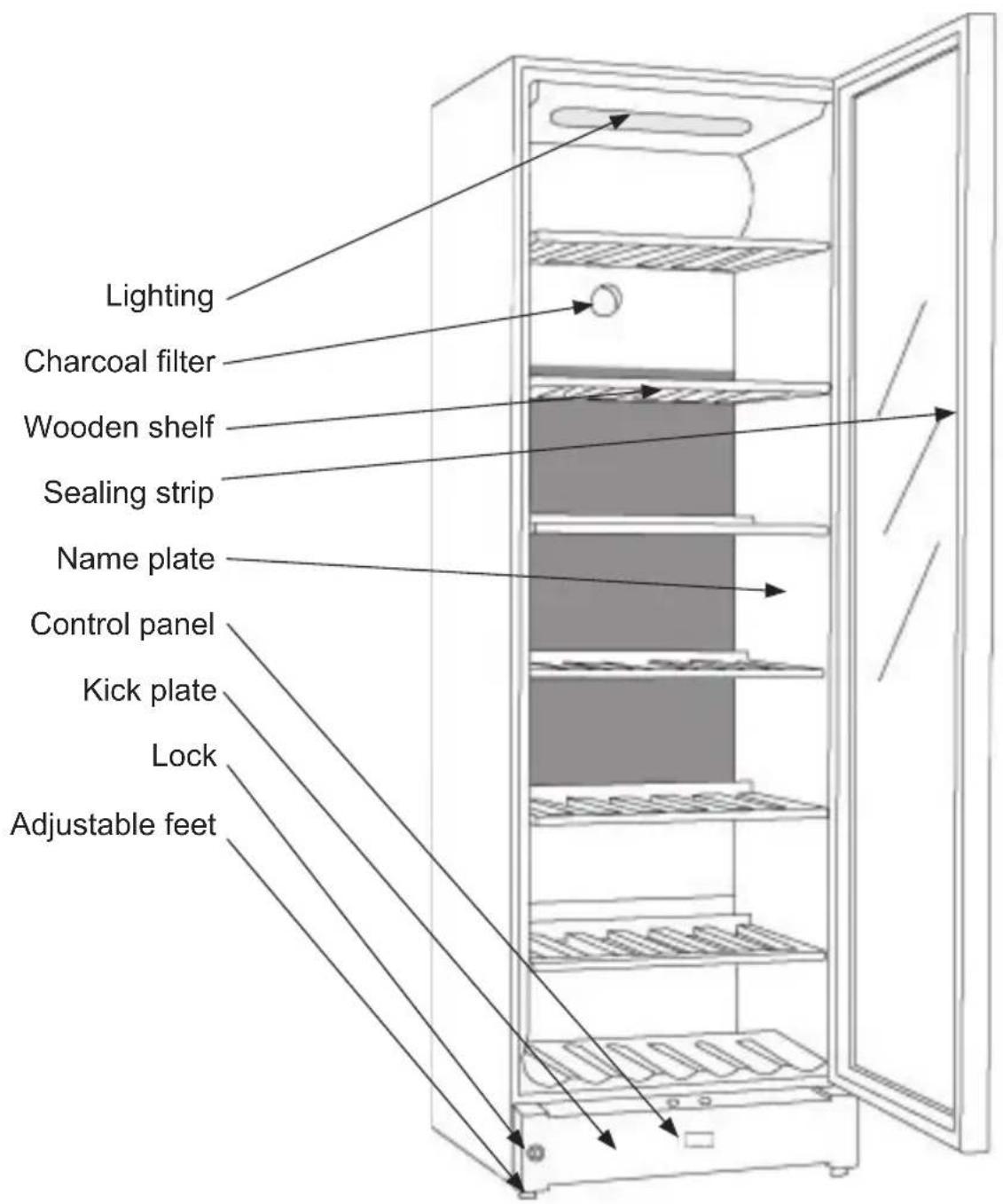
text_image
Lighting Charcoal filter Wooden shelf Sealing strip Name plate Control panel Kick plate Lock Adjustable feetfig.1
Electrical connection
Wiring and connections in power supply systems must been all applicable (local and national) electrical codes. Consult these codes lengths and sizes prior to cabinet installation.
This device complies with relevant EU directives including Low Voltage Directive 2014/35/EU and Electromagnetic Compatibility Directive 2014/30/EU
The socket should be freely accessible.
Connect the appliance only to 220/240 V / 50Hz alternating current via a correctly installed earthed socket.
The socket must be fused with a 10-13 A fuse.
If the appliance is to be operated in a non-European country, check on the rating plate whether the indicated voltage and current type correspond to the values of your mains supply.
Information regarding voltage, current or power are given on the rating plate
The power cord may be replaced by a technician only.
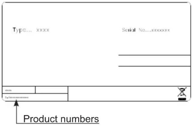
The rating plate provides various technical information as well as type and serial number.
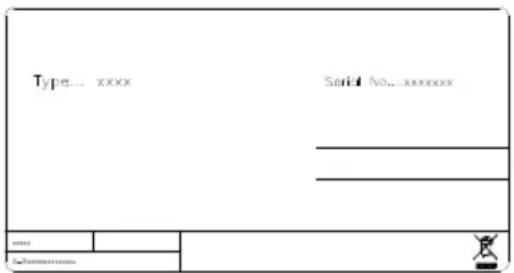
text_image
Type... xxxx Serial No... xxxxxxxx ... ... ... ... Name Informationfig.2
Installation and start-up
Placement
For safety and operational reasons, the appliance must not be installed outdoors.
The appliance should be placed on a level surface in a dry, well ventilated room (max. 75% relative air humidity). Never place the appliance close to sources of heat such as cookers or radiators, and avoid placing it in direct sunlight.
Ambient temperature
The climate class is stated on the name plate. This specifies the optimum ambient temperature. Wine coolers with winter position, however, function at ambient temperatures as low as 5^ C.
Room temperature
The climate class is stated on the name-plate. This specifies the optimum room temperature.
Note that the appliance operates best at room temperatures from 10^ C to 32^ C.
Installation
The surface on which the appliance is to be placed must be level. Do not use a frame or similar.
The appliance can be installed as a free-standing unit against a wall, built into a closet or lined up with other appliances.
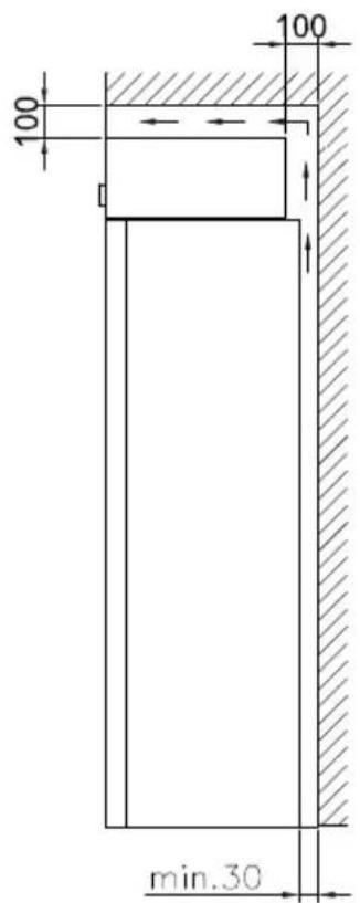
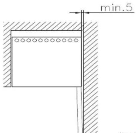
It is important that the appliance be well ventilated and that air can circulate unhindered above, below and around it.
The figures below illustrate how the necessary air circulation around the appliance can be ensured (figs 3).
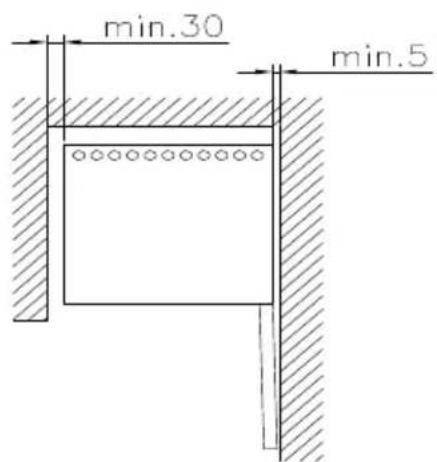
text_image
min.30 min.5fig. 4
text_image
100 100 min.30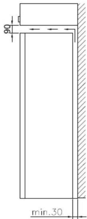
text_image
90 min.30fig. 3
text_image
min.5fig. 5
text_image
30 ° °fig. 6
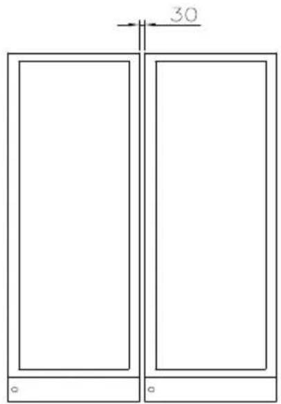
(fig 6) A "Side by Side" kit can be ordered
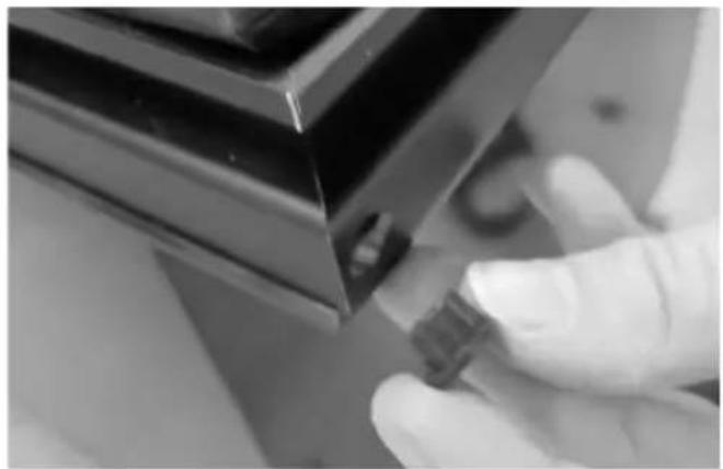
The distance pieces on the rear of the appliance ensure sufficient air circulation. Fit the two caps supplied with the appliance as shown in fig. 7.

natural_image
Line drawing of a hand inserting a plastic clip into a door panel (no text or symbols)fig. 7
Setting up
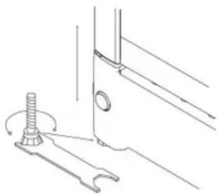
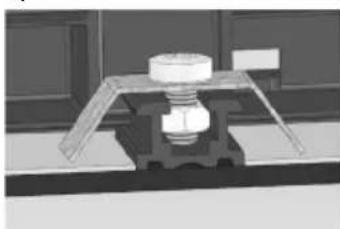
It is important that the appliance be absolutely level. It can be levelled by screwing the adjustable feet at the front of the appliance up or down (fig 8).
Use a spirit level to check that the appliance is absolutely level sideways.
natural_image
Technical line drawing of a mechanical component with a threaded bolt and base (no text or symbols)fig. 8

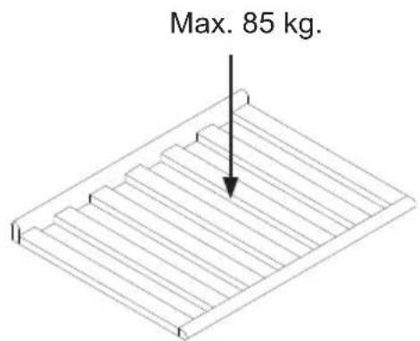
text_image
Max. 85 kg.Reversible door
Follow the instructions carefully
NOTE: Before you start the unit needs to be disconnected from the main grid.
We recommend that the change of door is done by a technician (we recommend two persons)
natural_image
Close-up of a hand using a screwdriver to adjust or install a mechanical component (no visible text or symbols)
natural_image
Interior view of a black server or computer chassis showing internal components and wiring (no visible text or labels)
natural_image
Interior view of a black server or computer chassis showing internal components and wiring (no visible text or labels)
natural_image
Close-up of a hand holding a white plastic clip attached to a black door handle (no text or symbols visible)4 mm Allen key;
Flat-headed screwdriver
Torx 20 (TX20) screwdriver
-
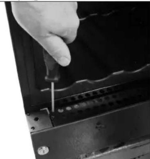
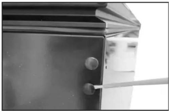
Open the door, unscrew the two screws fixing the bottom cover (Torx20). Do not remove the cover yet.
-
Place the appliance on its back (preferably on a soft foundation)
-
Loosen the upper hinge and remove it (4 mm Allen key)
natural_image
Close-up of a hand using a tool to cut or mark a metal component, no visible text or symbols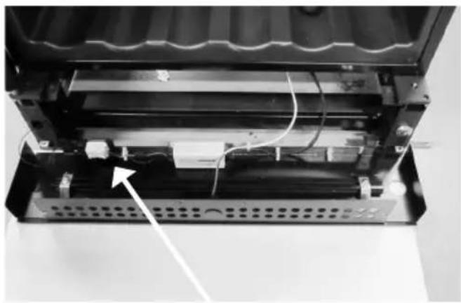
natural_image
Interior view of a device showing internal components and wiring, with no visible text or symbols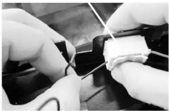
natural_image
Close-up of hands performing a soldering or wire repair operation on a black surface (no visible text or symbols)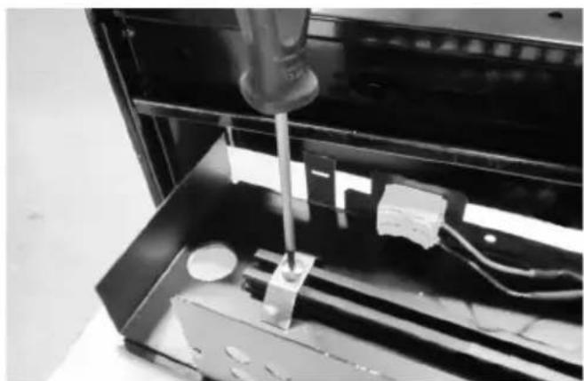
natural_image
Close-up of a mechanical device with a tool inserted into a black enclosure, showing internal components and wiring (no visible text or symbols)-
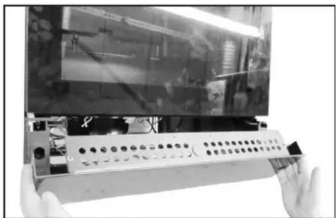
Dismount the bottom cover (the build-in snap function in each side can be unsnapped with the flat-headed screw-driver).
-
Place the bottom cover with glass front down, on an additional support, so the wires are not stretched.
-
The door LED wires have to be dismounted from the connector on the bottom cover (pure black & black / white stripe wires). Push the top release down to free the wire ends. (Note: the pure black wire is + and corresponds to the red wire on opposite side. The black / white stripe wire is 0 (neutral) and corresponds to the black wire on the opposite side – this is important when the wires are to be mounted later)
-
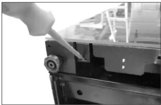
To reverse the bottom glass, the brackets need to be removed. Loosen the screw and the bracket incl. screw and bolt slides of the plastic profile.
natural_image
3D rendered mechanical assembly with a bolt and housing (no visible text or symbols)NOTE: Now the glass is loose.
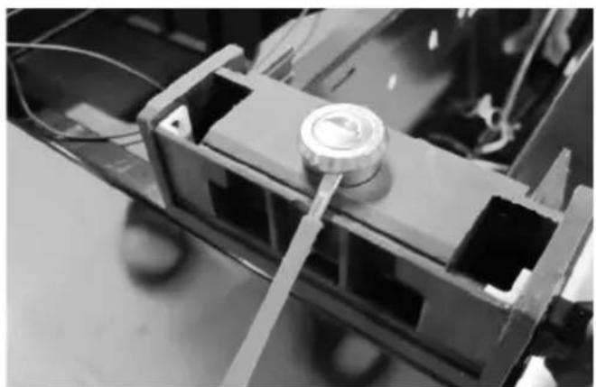
natural_image
Close-up of a mechanical component with reflective surfaces and mounting holes (no visible text or symbols)- Lift the bottom sheet metal part and turn the glass so the lock hole fits the other ends round ∅ hole concentric. Place the sheet metal part on the glass again, and mount the brackets onto the plastic profile in each end again. Don't over tighten the screws.
Note: The nut has to fit into the centre groove.
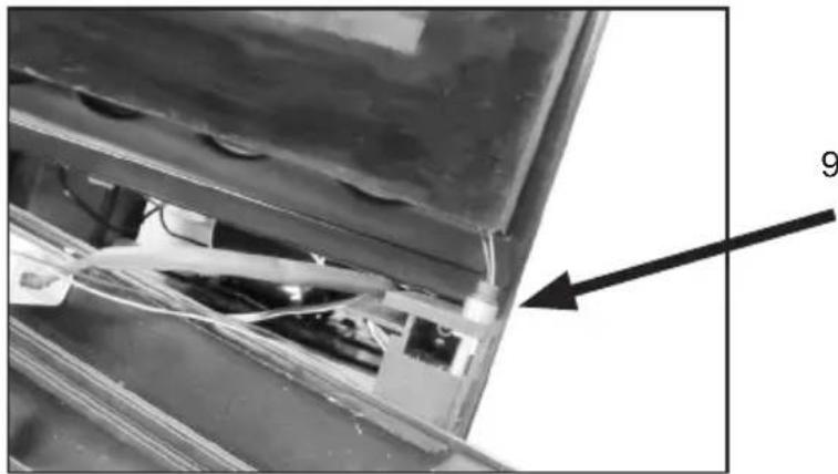
natural_image
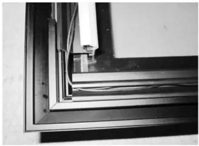
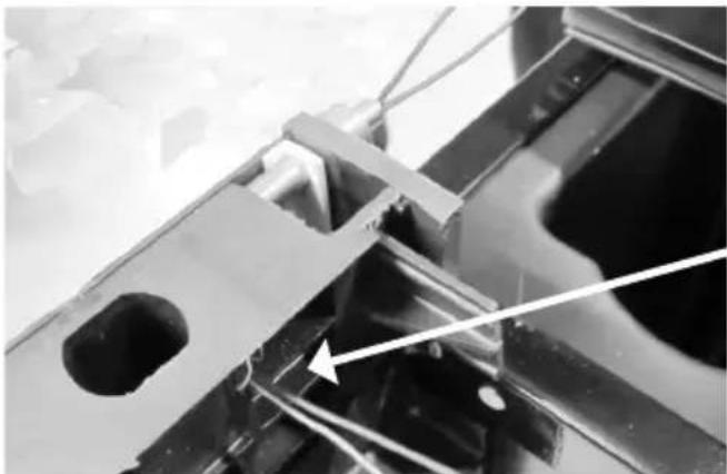
Close-up of a mechanical component with wires and a numbered annotation (9), no readable text or symbols present.- The door has to be moved up from the hinge.
natural_image
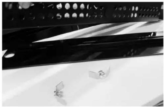
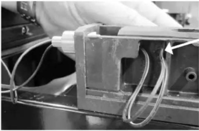
Close-up of a mechanical assembly with wires and a central component (no visible text or symbols)- Unscrew the lock pin (using the flat-headed screwdriver) and remove it.
natural_image
Close-up of a mechanical assembly with a central circular component and metal brackets (no visible text or symbols)- Pull up the lock cylinder and refit both lock cylinder and lock pin in opposite side.
natural_image
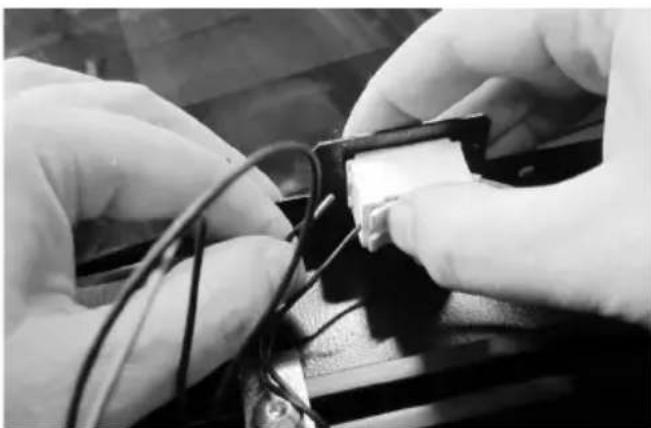
Close-up of hands connecting wires to a device component (no visible text or symbols)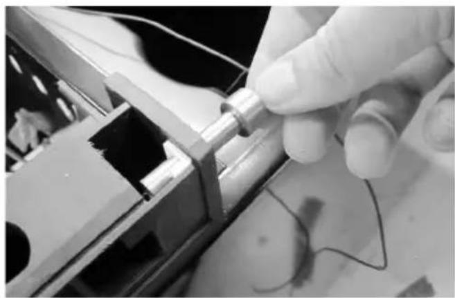
natural_image
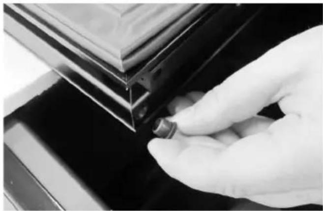
Close-up of a gloved hand holding a metallic cylindrical component with wires, no visible text or symbols
natural_image
Close-up of a glass window with curved black bands and a small human figure visible in the corner (no text or symbols)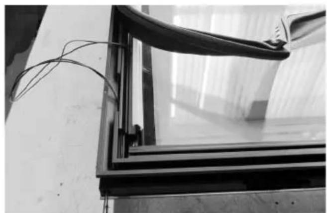
natural_image
Black-and-white photo of a glass-framed window with wires attached, no visible text or symbols-
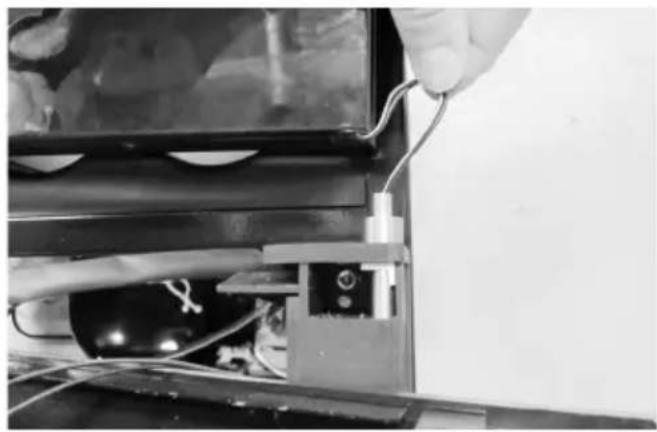
Pull the LED wires gently out of the bottom hinge pin.
-
Dismount the bottom hinge pin and fit it on the opposite side.
Note: The bush must also be moved.
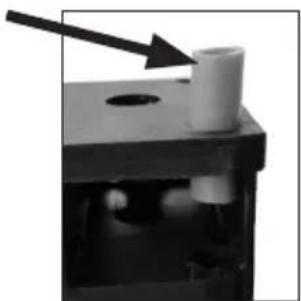
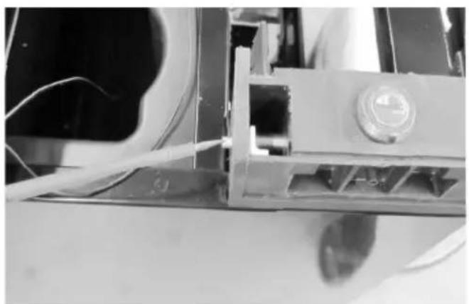
natural_image
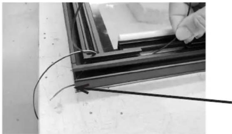
Close-up of a mechanical component with a white cylindrical part and an arrow pointing to it, no visible text or symbols.- Turn the door, so the glass side is down (Note: Place something between the glass and the other surface (cabinet) so scratch are minimized).
Then loosen the gasket on the low end of the door by pulling.
- Pull the LED wires up and out.
natural_image
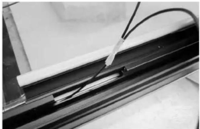
Close-up of a metal frame with visible wiring and a white cylindrical component inserted (no text or symbols)- Replace the wires into the plastic groove and lead them to the other side.
natural_image
Close-up of a hand holding wires next to a black metal frame, no visible text or symbols- Push the wires through the oblong hole and through the new hinge hole. This can be a bit tricky so try to mount only one wire first
natural_image
Close-up of a black metal frame with white insulation and coiled cable, no visible text or symbols- Then tape the second wire end to the first wire and pull them both fully through (remove tape subsequently).
natural_image
Close-up of a metal rod inserted into a concrete slab, with no visible text or symbols
natural_image
Close-up of a hand holding a flexible wire over a glass panel, mounted on a dark metal frame (no text or symbols visible)- Make sure the wires are fitted into the plastic groove and mount the gasket. It's important to check that the sealing strip provides a tight seal all the way round. If it does not, carefully heat the strip all the way round using a hair dryer. Then ease the strip slightly outwards so that it forms a tight seal against the cabinet. Be careful not to heat the strip so much that it melts!
natural_image
Close-up of a gloved hand adjusting a small mechanical component on a dark surface (no text or symbols visible)- Dismount the door hinge bushing and mount it on opposite side.

natural_image
Close-up of a hand holding a cable with a small object above, next to a black metal bracket (no text or symbols visible)- Pull the wire through the bushing before mounting it into the door hinge hole.

natural_image
Close-up of a gloved hand adjusting a metal bracket component (no visible text or symbols)- Reverse the door again and displace it a little on the cabinet proportion to the bottom hinge.
natural_image
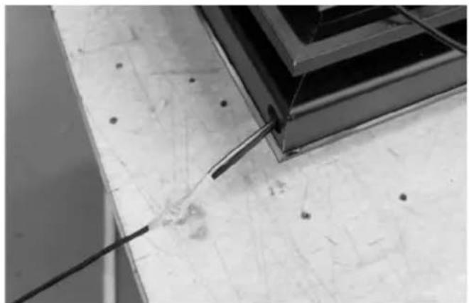
Close-up of a mechanical assembly with wires and a pipe fitting (no visible text or symbols)23.Pull the two wires through the bottom hinge pin....
natural_image
Close-up of a mechanical component with visible structural elements and a white arrow pointing to a specific part (no text or symbols present)24.... and through the wire hole in the plastic column.
natural_image
Close-up of hands assembling electronic components with wires (no visible text or symbols)- Remount the wires (se under # 6) and make sure that they are firmly secured.

natural_image
Close-up of a mechanical assembly with metallic components and wiring (no visible text or symbols)- Pusch the door back in place over the hinge pin and pull the wires simultaneously so the wire do not get stuck.
natural_image
Close-up of a gloved hand holding a small electronic component, no visible text or symbols- Dismount the top door bushing and mount it on opposite side.
natural_image
Close-up of a metallic door with a handle and circular button, no visible text or symbols- Dismount the plastic caps on the top of the cabinet and mount them on opposite side.

natural_image
Close-up of a metal door hinge with a black handle and mounting holes (no text or symbols visible)-
Make sure that the door is aligned with the cabinet before mounting the top hinge.
-
Remount the bottom front cover. Place the unit vertically again and mount the tow screws (see under # 1).
natural_image
Close-up of hands holding a remote control panel with a large screen in the background (no visible text or symbols)Note: Important: Wait approx. 12 hour before connecting the unit to the main grid.
Note: If the door LEDs don't give out light but the top LED in the cabinet is shining, it's most likely that the wires are not mounted correctly into the connector. (See under # 6 & 25)
Operation and function
text_image
SET 1 SET 2fig. 8
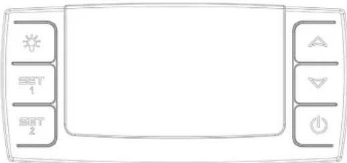
Electronic control
The electronic control ensures that the temperatures set at the top and at the bottom of the appliance are maintained. This is achieved by means of an advanced control of the refrigeration system, the heating element, and the fan. The set temperature will be stored in the event of power failure.
The electronic control has the following functions:
- On/off switch
- Light switch*
- Temperature setting
• Temperature indication - Alarm for too high and too low temperatures
- Door alarm
* The light may either be turned on constantly or only when the door is open.
Temperature indication
The display shows the actual temperature. The upper digits of the display indicate the temperature at the top of the appliance, and the lower digits of the display indicate the temperature at the bottom of the appliance. The temperature indicator is equipped with
a built-in filter which simulates the actual temperature in the bottles. Consequently, the indicator does not react on short-term fluctuations of the air temperature
Temperature setting
The thermostat is equipped with a child lock device. This device is activated by pushing the “up and down” buttons simultaneously. After approx. 3 seconds “Pof” flashes in the display. Then the actual temperatures are shown as usual. In addition, the set temperatures can be shown by pushing SET1 and SET2, respectively.
The child lock device is cancelled by pushing the "up and down" buttons simultaneously. After approx. 3 seconds "Pon" flashes in the display, and the temperature can be set.
Temperature setting at the top of the appliance
Push SET1. Then the temperature at the top of the appliance can be adjusted up and down by means of the "up and down" buttons. The temperature can be adjusted from 8 to 22°C, however so that the temperature cannot be set at a lower temperature than the actual set point for the bottom temperature sensor.
Temperature setting at the bot- tom of the appliance
Push SET2. Then the temperature at the bottom of the appliance can be adjusted up and down by means of the “up and down” buttons. The temperature can be adjusted from 5 to 22°C, however so that the temperature cannot be set at a higher temperature than the actual set point for the upper temperature sensor.
Alarm devices
There is a sub-alarm for the low-temperature sensor and an excess-alarm for the high-temperature sensor.
The alarm consists of a beeper and a warning on the display.
Alarm for high temperature: beep sound + alternating display of "HtA" and actual temperature
Alarm for low temperature: beep sound + alternating display of "LtA" and actual temperature
The alarm temperature depends on the set points.
The beep sound can be cancelled by pushing a random thermostat button. Push the on/off button to erase the display alarm, first for cancelling the alarm, then again for restarting the compressor.
Door alarm
When the door has been open for more than 2 minutes the door alarm is activated.
Light
To turn off the lights, press once
Permanent lighting
For presentation purposes of your wine, you can turn the lights permanently. Please press the light switch image twice. To switch off the lights press on again.
Two-zone setting for serving temperature
Typical serving temperature settings for the top and bottom sections are 16^ C and 6^ C respectively. With these settings, a suitable temperature gradient will be achieved in the cabinet for the storage of various types of wine distributed from top to bottom as follows:
- heavy red wines +16 to +19°C
- rosé and light red wines +12 to +16°C
- white wines +10 to +12°C
- champagne and sparkling wines +6 to +8°C
It is recommended that wine be served at a temperature which is a couple of degrees lower than the desired drinking temperature as the wine will be warmed slightly when it is poured into the glass.
Single-zone setting for long-term storage
For long-term wine storage, the top and bottom sections should both be set at 12^ C. With identical settings for the top and bottom sections, the controls will maintain an even temperature throughout the cabinet. However, the temperature in the room will gradually affect the temperature in the cabinet through its door and sides, creating a slight temperature gradient from top to
bottom. The controls will maintain the set temperature at the bottom of the cabinet, and any deviation from the setting will therefore occur at the top.
The difference will vary from 0 to 3°C, depending on the ambient temperature.
Defrosting, cleaning and maintenance.
Automatic defrosting.
The wine cooler is defrosted automatically. Defrost water runs through a pipe and is collected in a tray above the compressor where the heat generated by the compressor causes it to evaporate. The defrost water tray should be cleaned at intervals.
Cleaning.
Before cleaning the appliance, unplug it from the main supply. The cabinet is best cleaned using warm water (max. 65°C) with a little mild detergent. Never use cleaning agents that scour. Use a soft cloth. Rinse with clean water and dry thoroughly. The defrost water channel, in which condensation from the evaporator runs, is located at the bottom of the rear inside wall of the cabinet and must be kept clean. Add a few drops of disinfectant, e.g. Rodalon, to the defrost water drain a couple of times a year, and clean the drain using a pipe cleaner or similar. Never use sharp or pointed implements.
The sealing strip around the door must be cleaned regularly to prevent discolouration and prolong service life. Use clean water. After cleaning the sealing strip, check that it continues to provide a tight seal.
Dust collecting on the condenser on the rear of the cabinet, the compressor and in the compressor compartment is best removed using a vacuum cleaner.
Fault finding
| Fault Possible cause | Remedy | |
| The appliance is not working. | The appliance is switched off.Power failure; the fuse is blown; the appliance is not plugged in correctly. | Press the on/off switch.Check that power is connected.Reset the fuse. |
| Water collects in the bottom of the cabinet. | The defrost water pipe is blocked. | Clean the defrost water channel and the drain hole on the rear wall of the cabinet. |
| Vibration or bothersome noise. | The appliance is not level.The appliance is resting against other kitchen elements.Containers or bottles inside the cabinet are rattling against one another. | Level the appliance using a spirit level.Move the appliance away from the kitchen elements or appliances it is in contact with.Move containers and/or bottles apart. |
| Compressor runs continuously. | High room temperature. Ensure adequate ventilation. | |
| P1 is shown on the display. | The upper sensor is disconnected or short-circuited. | Call for service. The temperature within the entire cabinet is maintained at the higher of the two setpoints until the fault has been corrected. |
| P2 is shown on the display. | The lower sensor is disconnected or short-circuited. | Call for service. The temperature within the entire cabinet is maintained at the higher of the two setpoints until the fault has been corrected. |
Warranty, spare parts and service.
Warranty disclaimer
Faults and damage caused directly or indirectly by incorrect operation, misuse, insufficient maintenance, incorrect building, installation or mains connection. Fire, accident, lightening, voltage variation or other electrical interference, including defective fuses or faults in mains installations.
Repairs performed by others than approved service centres and any other faults and damage that the manufacturer can substantiate are caused by reasons other than manufacturing or material faults are not covered by the warranty.
Please note that changes to the construction of the appliance or changes to the component equipment of the appliance will invalidate warranty and product liability, and the appliance cannot be used lawfully. The approval stated on rating plate will also be invalidated.
Transport damage discovered by the buyer is primarily a matter to be settled between the buyer and the distributor, i.e. the distributor must ensure that such complaints are resolved to the buyer's satisfaction.
Before calling for technical assistance, please check whether you are able to rectify the fault yourself. If your request for assistance is unwarranted, e.g. if the appliance has failed as a result of a blown fuse or incorrect operation, you will be charged the costs incurred by your call for technical assistance.
Spare parts
When ordering spare parts, please state the type, serial and product numbers of your appliance. This information is given on the rating plate. The rating plate contains various technical information, including type and serial numbers.
text_image
Type... xxxx Serial No....xxxxxxxxx ... ... ... Product numbersDisposal
Information for Users on Collection and Disposal of Old Equipment and used Batteries
These symbols on the products, packaging, and/or accompanying documents mean that used electrical and electronic products and batteries should not be mixed with general household waste. For proper treatment, recovery and recycling of old products and used batteries, please take them to applicable collection points, in accordance with your national legislation and the Directives 2002/96/EC and 2006/66/EC.
By disposing of these products and batteries correctly, you will help to save valuable resources and prevent any potential negative effects on human health and the environment which could otherwise arise from inappropriate waste handling.
For more information about collection and recycling of old products and batteries, please contact your local municipality, your waste disposal service or the point of sale where you purchased the items.
Penalties may be applicable for incorrect disposal of this waste, in accordance with national legislation.
For business users in the European Union.
If you wish to discard electrical and electronic equipment, please contact your dealer or supplier for further information.
[Information on Disposal in other Countries outside the European Union]
These symbols are only valid in the European Union. If you wish to discard this product, please contact your local authorities or dealer and ask for the correct method of disposal.
Note for the battery symbol:
This symbol might be used in combination with a chemical symbol. In this case it complies with the requirement set by the Directive for the chemical involved.
Warnung
natural_image
Warning symbol of a flame inside a triangle (no text or numbers)WARNUNG:
text_image
Type... xxxx Serial No...xxxxxx _ _ _ mm _ _ Sub-xxxxxxAbb..2
natural_image
Line drawing of a hand holding a small object with a starburst symbol, no text or symbols presentfig. 6
Aufstellung
natural_image
Technical line drawing of a mechanical assembly with a bolt and lever (no text or symbols)fig. 7
text_image
Max. 85 kg.Wendbare Tür
natural_image
Close-up of a hand using a screwdriver to adjust or install a mechanical component (no visible text or symbols)
natural_image
Exterior view of a black server rack unit with internal components (no visible text or labels)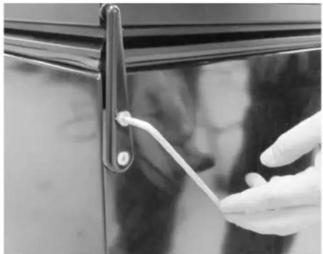
natural_image
Close-up of a hand holding a white plastic clip attached to a black door handle (no text or symbols visible)Hilfsmaterial:
4 mm Inbusschlüssel
natural_image
Close-up of a hand using a tool to cut or mark a metal component, no visible text or symbols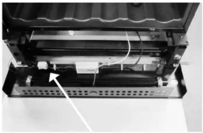
natural_image
Interior view of a device showing internal components and wiring, with an arrow pointing to a component (no visible text or symbols)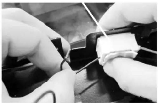
natural_image
Close-up of gloved hands performing a soldering or soldering operation on a circuit board (no visible text or symbols)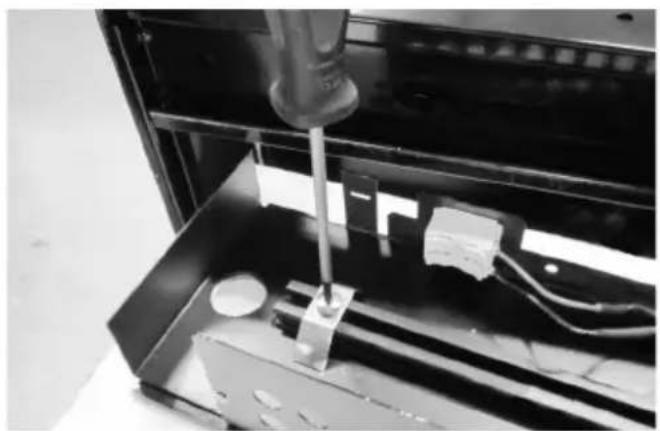
natural_image
Close-up of a mechanical testing setup with a tool inserted into a black enclosure, no visible text or symbolsnatural_image
3D rendered mechanical assembly with a cylindrical component mounted on a base plate (no visible text or symbols)natural_image
Close-up of a mechanical component with reflective surfaces and mounting holes (no visible text or symbols)natural_image
Close-up of a mechanical component with wires and a numbered annotation (9), no readable text or symbols present.natural_image
Close-up of a mechanical assembly with wires and a central component (no visible text or symbols)natural_image
Close-up of a mechanical assembly with a central circular component and metal brackets (no visible text or symbols)natural_image
Close-up of a hand inserting wires into a device component (no visible text or symbols)
natural_image
Close-up of a hand holding a metallic cylindrical component, with visible wiring and mechanical components (no text or symbols)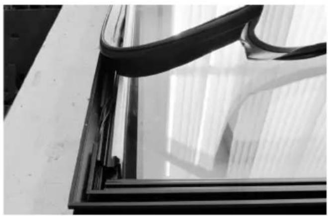
natural_image
Close-up of a glass window frame with black plastic wrap and sheer curtains, no visible text or symbols
natural_image
Close-up of a glass-framed window with visible insulation and wiring, mounted on a wooden surface (no text or symbols)natural_image
Close-up of a mechanical component with a white cylindrical part inserted, showing internal structure and an arrow indicating direction (no text or symbols)natural_image
Close-up of a metal frame with visible wiring and a white cylindrical component inserted (no text or symbols)natural_image
Close-up of a hand holding wires next to a black metal frame, no visible text or symbolsnatural_image
Close-up of a black metal frame with white insulation and coiled cable, no visible text or symbolsnatural_image
Close-up of a metal rod inserted into a concrete slab, with no visible text or symbols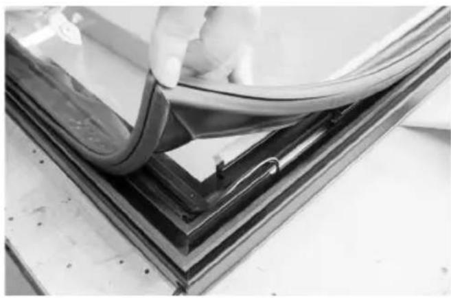
natural_image
Close-up of a hand holding a flexible wire over a glass panel, mounted on a dark metal frame (no text or symbols visible)natural_image
Close-up of a gloved hand adjusting a small mechanical component on a dark surface (no text or symbols visible)natural_image
Close-up of a hand holding a cable with a small object above it, next to a black metal bracket (no text or symbols visible)natural_image
Close-up of a gloved hand adjusting a metal bracket component (no visible text or symbols)natural_image
Close-up of a mechanical assembly with metal components and wires, no visible text or symbolsnatural_image
Close-up of a mechanical assembly with visible structural components and a white arrow pointing to a specific part (no text or symbols present)natural_image
Close-up of hands assembling electronic components with wires (no visible text or symbols)natural_image
Close-up of a mechanical assembly with internal components and no visible text or symbolsnatural_image
Close-up of a gloved hand holding a small electronic component, no visible text or symbols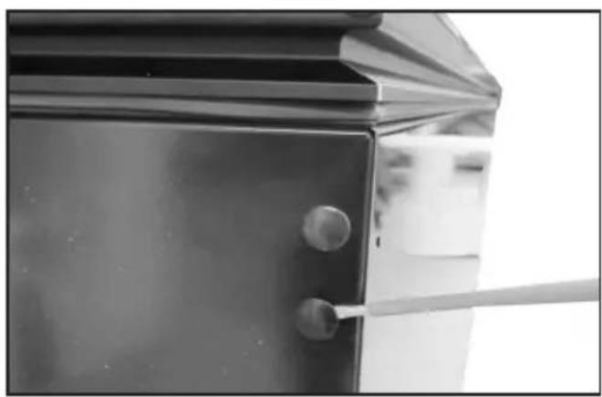
natural_image
Close-up of a metallic door with a handle and circular button, no visible text or symbols
natural_image
Close-up of a metal door hinge with a black handle and mounting holes (no text or symbols visible)
natural_image
Close-up of hands holding a control panel with a monitor displaying a screen (no visible text or symbols)text_image
SET 1 SET 2Abb. 8
text_image
Type... xxxx Serial No...xxxxxxxxx Product number.text_image
Warning sign depicting a flame symbol in a triangular shape, commonly used to indicate hazard or caution.natural_image
Line drawing of a hand inserting a plastic clip into a door panel (no text or symbols)fig. 7
Opstilling
natural_image
Technical line drawing of a mechanical assembly with a threaded component and base (no text or symbols)fig. 8
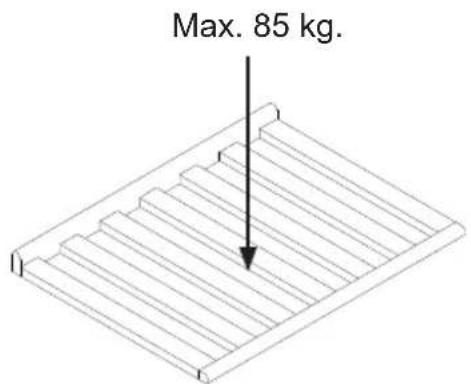
text_image
Max. 85 kg.Vendbar dør
natural_image
Close-up of a hand using a screwdriver to adjust or install a mechanical component (no visible text or symbols)4 mm 6kant nøgle
natural_image
Black server rack unit with visible internal components and ventilation slots (no text or symbols)natural_image
Close-up of a hand holding a white plastic clip attached to a black door handle (no text or symbols visible)natural_image
Close-up of a hand using a tool to cut or mark a metal component, no visible text or symbols
natural_image
Interior view of a device showing internal components and wiring, with no visible text or symbols
natural_image
Close-up of hands performing a soldering or wire repair operation on a black surface (no visible text or symbols)
natural_image
Close-up of a mechanical testing setup with a tool inserted into a metal enclosure (no visible text or symbols)natural_image
3D rendering of a mechanical assembly with a cylindrical component mounted on a base (no visible text or symbols)natural_image
Close-up of a mechanical component with reflective surfaces and mounting holes (no visible text or symbols)natural_image
Close-up of a mechanical component with wires and a numbered annotation (9), no readable text or symbols present.natural_image
Close-up of a mechanical assembly with wires and a central component (no visible text or symbols)natural_image
Close-up of a mechanical assembly with a central circular component and metal brackets (no visible text or symbols)natural_image
Close-up of a hand inserting wires into a device component (no visible text or symbols)
natural_image
Close-up of a hand holding a metallic cylindrical component, with visible wiring and mechanical components (no text or symbols)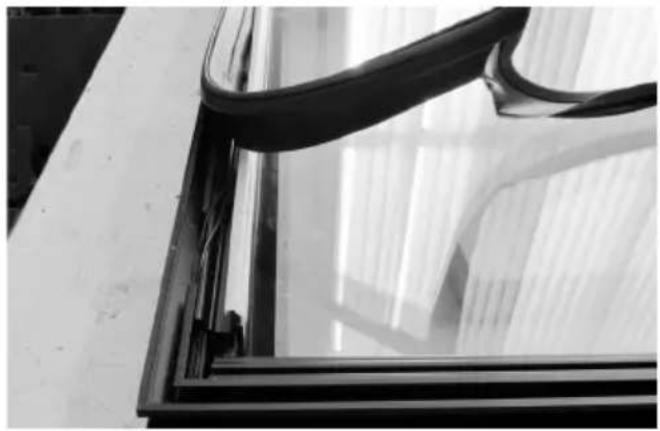
natural_image
Close-up of a glass window frame with curved black bands, no visible text or symbols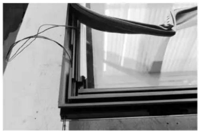
natural_image
Close-up of a glass-framed window with visible insulation and wiring, mounted on a wall (no text or symbols)natural_image
Close-up of a mechanical component with a white cylindrical part and an arrow pointing to it, no visible text or symbols.natural_image
Close-up of a metal frame with visible wiring and a white cylindrical component inserted (no text or symbols)natural_image
Close-up of a hand holding wires next to a black metal frame, no visible text or symbolsnatural_image
Close-up of a black metal frame with white insulation and coiled cable, no visible text or symbolsnatural_image
Close-up of a metal rod inserted into a concrete slab, with no visible text or symbols
natural_image
Close-up of a hand holding a flexible cable over a glass panel, with no visible text or symbols.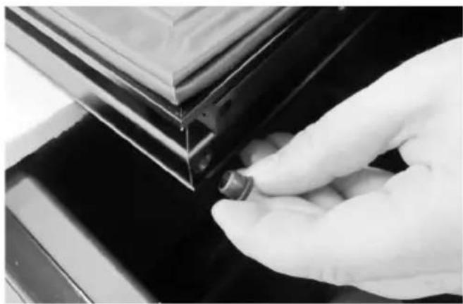
natural_image
Close-up of a gloved hand adjusting a small mechanical component against a dark surface (no text or symbols visible)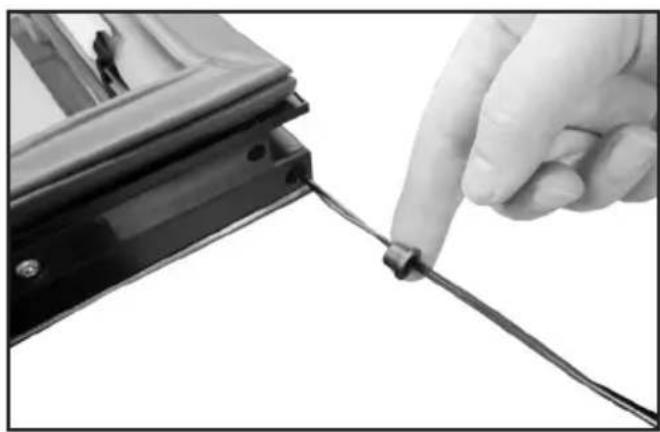
natural_image
Close-up of a hand holding a cable with a small connector, next to a black metal bracket (no text or symbols visible)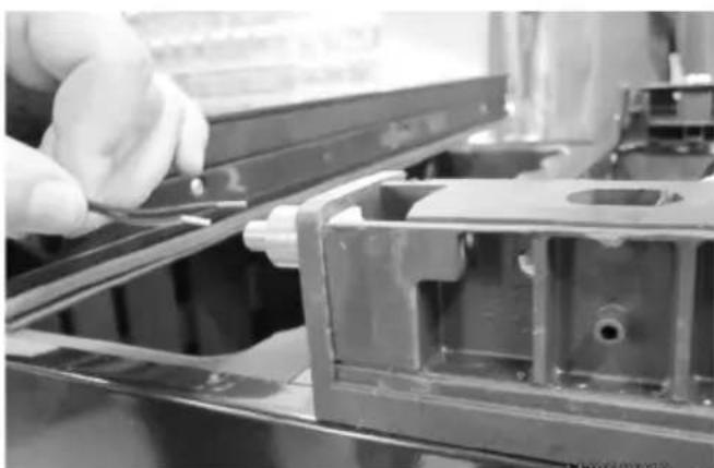
natural_image
Close-up of a gloved hand adjusting a metal bracket component (no visible text or symbols)natural_image
Close-up of a mechanical assembly with wires and a pipe fitting (no visible text or symbols)natural_image
Close-up of a mechanical component with visible structural elements and a white arrow pointing to a specific part (no text or symbols)natural_image
Close-up of hands assembling electronic components with wires (no visible text or symbols)natural_image
Close-up of a mechanical assembly with metallic components and wiring (no visible text or symbols)natural_image
Close-up of a gloved hand holding a small electronic component, no visible text or symbolsnatural_image
Close-up of a metallic door with a handle and circular button, no visible text or symbolsnatural_image
Close-up of a metal bracket with a pull rod and mounting holes (no text or symbols visible)natural_image
Close-up of hands holding a remote control panel with a large screen in the background (no visible text or symbols)text_image
SET 1 SET 2fig. 8
Elektronisk styring.
Temperatur-indstilling.
GB Reserving the right to alter specifications without prior notice.