
T-405TX - Audio tuner ONKYO - Free user manual and instructions
Find the device manual for free T-405TX ONKYO in PDF.


| Product Type | FM Stereo Tuner |
| Model | T-405TX |
| Brand | Onkyo |
| Power Supply | AC 120 V, 60 Hz (U.S. & Canadian models) / AC 230-240 V, 50 Hz (other models) |
| Power Consumption | 9 W |
| FM Tuning Range | 87.90 - 107.90 MHz (200 kHz steps) for U.S./Canada; 87.50 - 108.00 MHz (50 kHz steps) for other areas |
| FM Usable Sensitivity (Mono) | 12.8 dBf (1.2 µV, 75 ohms IHF) |
| FM Usable Sensitivity (Stereo) | 19.2 dBf (2.5 µV, 75 ohms IHF) |
| FM Frequency Response | 30 - 15,000 Hz (±1.5 dB) |
| FM Signal-to-Noise Ratio (Mono) | 73 dB IHF |
| FM Signal-to-Noise Ratio (Stereo) | 66 dB IHF |
| AM Tuning Range | 530 - 1,710 kHz (10 kHz steps, U.S. & Canadian models only) |
| Preset Memory | Up to 30 stations (20 FM + 10 AM for U.S./Canada; 20 FM for others) |
| Auto Preset Memory | Yes (automatically scans and stores stations with best signals) |
| Timer Functions | Weekly Program Timer (playback and recording), Sleep Timer |
| RDS Support | Yes (European models only): PS (Program Service Name) and RT (Radio Text) |
| Clock | ACCUCLOCK automatic setting via RDS or manual setting, 12/24 hour display |
| Display | Fluorescent dot matrix display showing frequency, time, preset number, RDS info, timer settings |
| Antenna Inputs | FM 75 ohms coaxial, AM loop or outdoor (U.S./Canada) |
| Audio Outputs | 1 pair RCA (L/R), output level: 0.5 V (U.S./Canada) / 0.75 V (other areas) |
| Remote Control | Not included separately; can be operated via Onkyo A-905TX amplifier remote (RC-456S) through RI connection |
| Accessories Included | Audio connection cable, RI remote control cable, FM indoor antenna; U.S./Canada also include AM loop antenna and T-shaped FM indoor antenna |
| Safety Features | Polarized plug, grounding provisions, power cord protection, heat/ventilation requirements |
| Dimensions (Approximate) | Not specified in manual; typical width 435 mm, height 70 mm, depth 280 mm |
| Weight (Approximate) | Not specified; typical around 3.5 kg |
Frequently Asked Questions - T-405TX ONKYO
User questions about T-405TX ONKYO
0 question about this device. Answer the ones you know or ask your own.
Ask a new question about this device
Download the instructions for your Audio tuner in PDF format for free! Find your manual T-405TX - ONKYO and take your electronic device back in hand. On this page are published all the documents necessary for the use of your device. T-405TX by ONKYO.
USER MANUAL T-405TX ONKYO
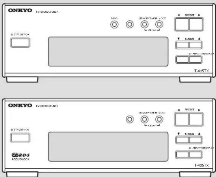
FM Stereo Tuner T-405TX
Instruction Manual
Before using
Thank you for purchasing ...
Thank you for purchasing the ONKYO T-405TX Tuner.
Please read this manual thoroughly before making any connection or turning on the power.
Follow these instructions to obtain optimum performance and maximum listening enjoyment from your new Tuner. Please retain this manual for future reference.
Main Features
• High-Quality Separate Component
- Preset Memory for Up to 30 Broadcast Stations
• Auto Preset Memory Function
• Weekly Program Timer
WARNING:
TO REDUCE THE RISK OF FIRE OR ELECTRIC SHOCK, DO NOT EXPOSE THIS APPLIANCE TO RAIN OR MOISTURE.
CAUTION:
TO REDUCE THE RISK OF ELECTRIC SHOCK, DO NOT REMOVE COVER (OR BACK). NO USER-SERVICEABLE PARTS INSIDE. REFER SERVICING TO QUALIFIED SERVICE PERSONNEL.
WARNING
RISK OF ELECTRIC SHOCK DO NOT OPEN
AVIS
RISQUE DE CHOC ELECTRIQUE NE PAS OUVRIR


The lightning flash with arrowhead symbol, within an equilateral triangle, is intended to alert the user to the presence of uninsulated “dangerous voltage” within the product’s enclosure that may be of sufficient magnitude to constitute a risk of electric shock to persons.

The exclamation point within an equilateral triangle is intended to alert the user to the presence of important operating and maintenance (servicing) instructions in the literature accompanying the appliance.
Important Safeguards
- Read Instructions – All the safety and operating instructions should be read before the appliance is operated.
- Retain Instructions – The safety and operating instructions should be retained for future reference.
- Heed Warnings – All warnings on the appliance and in the operating instructions should be adhered to.
-
Follow Instructions – All operating and use instructions should be followed.
-
Water and Moisture – The appliance should not be used near water – for example, near a bathtub, washbowl, kitchen sink, laundry tub, in a wet basement, or near a swimming pool, and the like.
- Carts and Stands – The appliance should be used only with a cart or stand that is recommended by the manufacturer.
6A. An appliance and cart combination should be moved with care. Quick stops, excessive force, and uneven surfaces may cause the appliance and cart combination to overturn.
PORTABLE CART WARNING

natural_image
Silhouette of a person climbing a ladder inside a circular frame (no text or symbols)- Wall or Ceiling Mounting – The appliance should be mounted to a wall or ceiling only as recommended by the manufacturer.
- Ventilation – The appliance should be situated so that its location or position does not interfere with its proper ventilation. For example, the appliance should not be situated on a bed, sofa, rug, or similar surface that may block the ventilation openings; or if placed in a built-in installation, such as a bookcase or cabinet that may impede the flow of air through the ventilation openings, there should be free space of at least 5 cm (2 in.) and an opening behind the appliance.
- Heat – The appliance should be situated away from heat sources such as radiators, heat registers, stoves, or other appliances (including amplifiers) that produce heat.
- Power Sources – The appliance should be connected to a power supply only of the type described in the operating instructions or as marked on the appliance.
- Polarization – If the appliance is provided with a polarized plug having one blade wider than the other, please read the following information: The polarization of the plug is a safety feature. The polarized plug will only fit the outlet one way. If the plug does not fit fully into the outlet, try reversing it. If there is still trouble, the user should seek the services of a qualified electrician. Under no circumstances should the user attempt to defeat the polarization of the plug.
- Power-Cord Protection – Power-supply cords should be routed so that they are not likely to be walked on or pinched by items placed upon or against them, especially near plugs, convenience receptacles, and the point where they exit from the appliance.
- Cleaning – The appliance should be cleaned only as recommended by the manufacturer.
- Power Lines – An outdoor antenna should be located away from power lines.
- Nonuse Periods – The power cord of the appliance should be unplugged from the outlet when left unused for a long period of time.
-
Object and Liquid Entry – Care should be taken so that objects do not fall and liquids are not spilled into the enclosure through openings.
-
Damage Requiring Service – The appliance should be serviced by qualified service personnel when:
A. The power-supply cord or the plug has been damaged; or
B. Objects have fallen, or liquid has been spilled into the appliance; or
C. The appliance has been exposed to rain; or
D. The appliance does not appear to operate normally or exhibits a marked change in performance; or
E. The appliance has been dropped, or the enclosure damaged.
- Servicing – The user should not attempt to service the appliance beyond that described in the operating instructions. All other servicing should be referred to qualified service personnel.
- Outdoor Antenna Grounding – If an outside antenna is connected to the receiver, be sure the antenna system is grounded so as to provide some protection against voltage surges and built up static charges. Article 810 of the National Electrical Code, ANSI/NFPA 70, provides information with regard to proper grounding of the mast and supporting structure, grounding of the lead-in wire to an antenna-discharge unit, size of grounding conductors, location of antenna-discharge unit, connection to grounding electrodes, and requirements for the grounding electrode. See Figure 1.
FIGURE 1:
EXAMPLE OF ANTENNA GROUNDING AS PER NATIONAL ELECTRICAL CODE

NEC - NATIONAL ELECTRICAL CODE
Precautions
1. Warranty Claim
You can find the serial number on the rear panel of this unit. In case of warranty claim, please report this number.
2. Care
From time to time you should wipe the front and rear panels and the cabinet with a soft cloth. For heavier dirt, dampen a soft cloth in a weak solution of mild detergent and water, wring it out dry, and wipe off the dirt. Following this, dry immediately with a clean cloth. Do not use rough material, thinners, alcohol or other chemical solvents or cloths since these could damage the finish or remove the panel lettering.
3. Power
WARNING
BEFORE PLUGGING IN THE UNIT FOR THE FIRST TIME, READ THE FOLLOWING SECTION CAREFULLY.
The voltage of the available power supply differs according to country or region. Be sure that the power supply voltage of the area where this unit will be used meets the required voltage (e.g., AC 230 V, 50 Hz or AC 120 V, 60 Hz) written on the rear panel.
Setting the STANDBY button to standby does not shut off the power completely. So the power cord should be removed from the AC outlet when the unit is not used for a prolonged time.
For British model
Replacement and mounting of an AC plug on the power supply cord of this unit should be performed only by qualified service personnel.
IMPORTANT
The wires in the mains lead are coloured in accordance with the following code:
Blue : Neutral
Brown : Live
As the colours of the wires in the mains lead of this apparatus may not correspond with the coloured markings identifying the terminals in your plug, proceed as follows:
The wire which is coloured blue must be connected to the terminal which is marked with the letter N or coloured black.
The wire which is coloured brown must be connected to the terminal which is marked with the letter L or coloured red.
IMPORTANT
A 5 ampere fuse is fitted in this plug. Should the fuse need to be replaced, please ensure that the replacement fuse has a rating of 5 amperes and that it is approved by ASTA or BSI to BS1362. Check for the ASTA mark or the BSI mark on the body of the fuse. IF THE FITTED MOULDED PLUG IS UNSUITABLE FOR THE SOCKET OUTLET IN YOUR HOME THEN THE FUSE SHOULD BE REMOVED AND THE PLUG CUT OFF AND DISPOSED OF SAFELY. THERE IS A DANGER OF SEVERE ELECTRICAL SHOCK IF THE CUT OFF PLUG IS INSERTED INTO ANY 13 AMPERE SOCKET. If in any doubt, please consult a qualified electrician.
For U.S. model
Note to CATV system installer:
This reminder is provided to call the CATV system installer's attention to Article 820-40 of the NEC, ANSI/NFPA 70, which provides guidelines for proper grounding and, in particular, specifies that the cable ground shall be connected to the grounding system of the building, as close to the point of cable entry as practical.
FCC Information for User
CAUTION:
The user changes or modifications not expressly approved by the party responsible for compliance could void the user's authority to operate the equipment.
NOTE:
This equipment has been tested and found to comply with the limits for a Class B digital device, pursuant to Part 15 of the FCC Rules. These limits are designed to provide reasonable protection against harmful interference in a residential installation. This equipment generates, uses and can radiate radio frequency energy and, if not installed and used in accordance with the instructions, may cause harmful interference to radio communications. However, there is no guarantee that interference will not occur in a particular installation. If this equipment does cause harmful interference to radio or television reception, which can be determined by turning the equipment off and on, the user is encouraged to try to correct the interference by one or more of the following measures:
- Reorient or relocate the receiving antenna.
- Increase the separation between the equipment and receiver.
- Connect the equipment into an outlet on a circuit different from that to which the receiver is connected.
- Consult the dealer or an experienced radio/TV technician for help.
For Canadian model
For models having a power cord with a polarized plug:
CAUTION: TO PREVENT ELECTRIC SHOCK, MATCH WIDE BLADE OF PLUG TO WIDE SLOT, FULLY INSERT.
Connecting to the ONKYO Separate Collection Series Components 6
Connecting to other components 8
Antenna connections 10
Operation
Setting the Clock 12
Receiving stations 16
Naming a preset station 19
Receiving RDS (European models only) 22
Using the timer 23
Other Information
Troubleshooting 30
Index to parts and controls 31
Specifications 32
Supplied accessories
Check that the following accessories are supplied with this unit.
natural_image
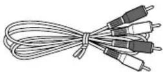
Coiled cable with multiple colored connectors (no text or symbols visible)Audio connection cable · 1

RI remote control cable · 1
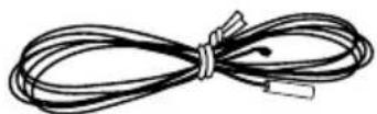
FM indoor antenna · 1
(not available on the U.S. and Cnadian models)

AM loop antenna · 1
(only available on the U.S. and Canadian models)

natural_image
Illustration of a bundle of coiled wires or cables (no text or symbols)T-shaped FM indoor antenna · 1
(only available on the U.S. and Canadian models)
Declaration of Conformity
We, ONKYO EUROPE ELECTRONICS GmbH INDUSTRIESTRASSE 20 82110 GERMERING, GERMANY

declare in own responsibility, that the ONKYO product described in this instruction manual is in compliance with the corresponding technical standards such as EN60065, EN55013, EN55020 and EN61000-3-2, -3-3.
GERMERING, GERMANY
ONKYO EUROPE ELECTRONICS GmbH
Memory Preservation
This unit does not require memory preservation batteries. A built-in memory power back-up system preserves the contents of the memory during power failures and even when the unit is unplugged. The unit must be plugged in order to charge the back-up system.
The memory preservation period after the unit has been unplugged varies depending on climate and placement of the unit. On the average, memory contents are protected over a period of a few weeks after the last time the unit has been unplugged. This period is shorter when the unit is exposed to a highly humid climate.
Connections
Connecting to the ONKYO Separate Collection Series Components
This section introduces you to the other Separate Collection Series system components and their convenient system functions, followed by instruction on how to connect the system.
The following Separate Collection Series components are available:
• A-905TX ...... Integrated Stereo Amplifier
• C-705TX .... Compact Disc (CD) Player (Not available in U.S. and Canada)
• C-707CHX ...... Compact Disc (CD) Changer (Only available in U.S. and Canada)
• K-505TX ...... Stereo Cassette Tape Deck
- MD-105TX ...... Minidisc (MD) Recorder (Not available in U.S. and Canada)
- CDR-205TX ...... Compact Disc (CD) Recorder (available only in part of Asia)
Note that the available components may vary according to the area.
Combining the T-405TX Stereo tuner with the above system components enables you to operate the following convenient functions:
- Auto Power On
- You can turn on the power to the amplifier by pressing the STANDBY/ON button on one of the system components. (The amplifier's POWER switch must be set to ON.)
- When the amplifier's POWER switch is set to ON, you can turn on the power to all the system components simultaneously by pressing the STANDBY/ON button on the amplifier.
Afterwards, you can turn off the power to the individual components that are not in use.
- Direct Change
Press the following button on the component you want to operate. The amplifier will automatically select the input from the corresponding component:
- The play button on the CD player (or changer), MD recorder, or stereo cassette tape deck; or
- The PRESET ◀/▶ buttons on the tuner.
- Remote Control Operation
You can operate all the system components using the remote controller supplied with the amplifier A-905TX.
- Program Timer
You can operate the timer playback and recording functions using the T-405TX (see page 23).
- Sleep Timer
You can fall asleep to a music/radio program using the timer (see page 29).
- CD Dubbing
Simple CD dubbing using a stereo cassette tape deck or MD recorder is possible with the pressing of a single button (CD dubbing function using an MD recorder is not available on the C-707CHX). (Refer to the K-505TX or MD-105TX Instruction Manual for more information).
• CD/MD Synchro Recording
When using a stereo cassette tape deck, MD recorder or CD recorder to record from the CD player or when using a stereo cassette tape deck to record from an MD recorder, you can record with simply starting on a CD player or MD recorder. (Refer to the K-505TX, MD-105TX or CDR-205TX instruction manual for more information.)
- Dubbing a specific track from CD
You can specify a track on a CD and easily dub it to a connected MD recorder or CD recorder. (Refer to the MD-105TX or CDR-205TX instruction manual for more information.)
System connection for use of Timer function
If you wish to use the Timer function of this unit in your system, connect the power cord as shown below and connect the RI cable and audio connection cables.
- Be sure to connect the power cord of this unit to an AC outlet that supplies continuous power.
- Turn on the POWER switch on the amplifier A-905TX. If you turn off the POWER switch, the Timer function setting will be cancelled.
- Be sure to make the audio cable connection. Refer to the instruction manual for the A-905TX for information on audio cable connection.

Notes
You can turn off the power to the entire system by simply turning off the POWER switch on the A-905TX Amplifier, refer to the A-905TX instruction manual for more information.
The 230 V models are shown in the illustrations.
Using the remote controller
The unit is not shipped with a remote controller. However, you may use a remote controller (RC-456S) that is supplied with A-905TX amplifier to operate the unit.
Be sure to make the RI connection securely. If the connection is incomplete, you cannot use the remote controller to operate the unit.
Point the remote controller toward the remote control sensor of A-905TX. T405TX

Notes
- Place the unit away from strong light such as direct sunlight or inverted fluorescent light which can prevent proper operation of the remote controller.
- Using another remote controller of the same type in the same room or using the unit near equipment which uses infrared rays may cause operational interference.
- Do not put any object such as a book on the remote controller. The buttons of the remote controller may be pressed by mistake and drain the batteries.
• Make sure the audio rack doors do not have colored glass. Placing the unit behind such doors may prevent proper remote controller operation. - If there is any obstacle between the remote controller and the remote control sensor, the remote controller will not operate.
Connecting to other components
Before connecting
- Do not connect the unit's AC power cord to a wall outlet until you have completed all the other connections.
- On each pair of connectors, a red connector (marked R) corresponds to the right channel, and a white connector (marked L) to the left channel. Connect white plugs of audio connection cables to L connectors and connect red plugs of audio connection cables to R connectors.

- Insert the plug securely. If the connection is incomplete, noise or malfunction may result.

- Bundling an audio connection cable with the power cord or speaker cord may degrade the sound quality.
Note:
The 230-240 V model is shown in the following illustrations.
Connections
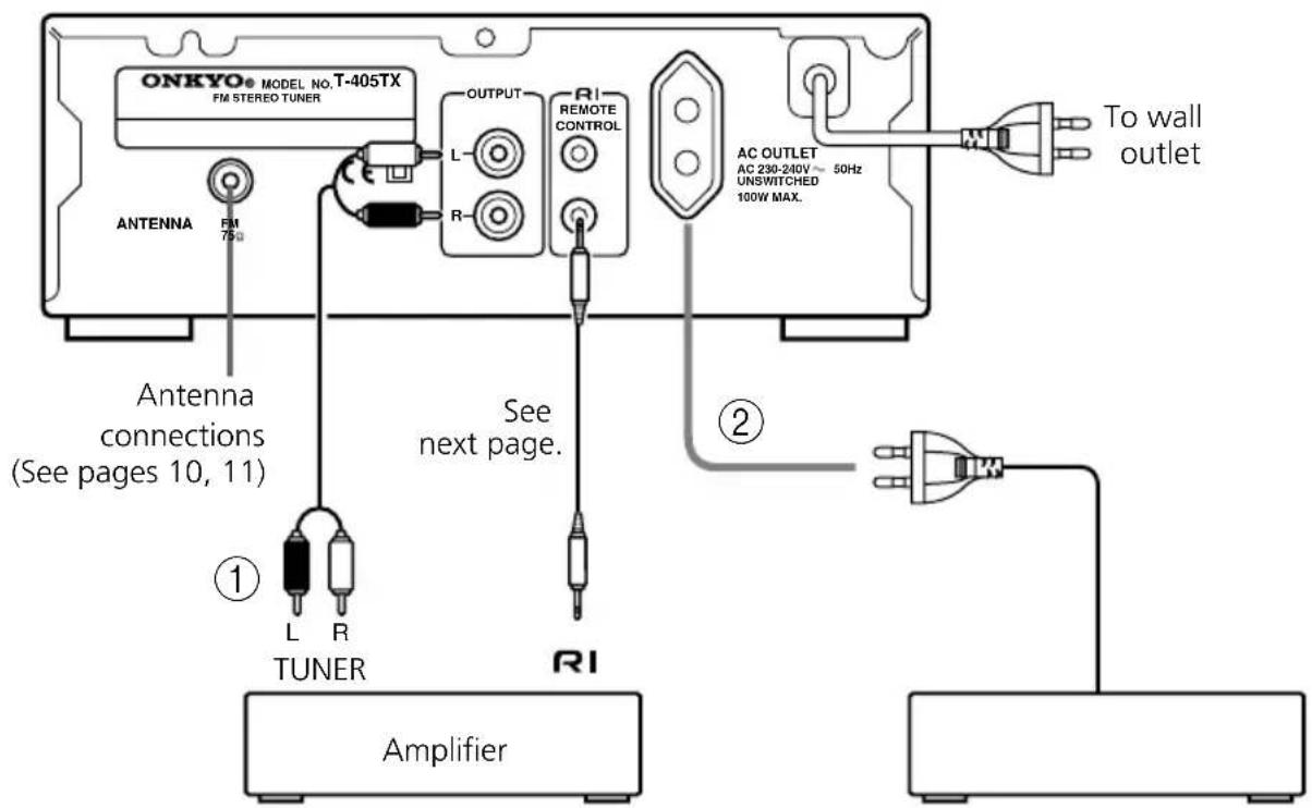
① Connecting the amplifier
Connect the tuner's OUTPUT jacks and the amplifier's TUNER input jacks using the audio connection cable. Refer to the amplifier's instruction manual for connection information.
② AC outlet (UNSWITCHED)
The AC power cord of another component can be connected to this AC OUTLET connector.
This means that if the T-405TX is plugged into an AC outlet, AC power is available to this AC OUTLET even if the T-405TX is off.
The shape and capacity of the AC outlet may differ depending on the area of purchase. Make sure that the capacity of other components connected to this unit does not exceed the capacity that is printed on the rear panel.

Connecting the Connector
If you are using other ONKYO components equipped with R connectors, you can control these components using the amplifier's remote controller.
Before connecting
- The amplifier must be connected to the RI system hookups for R control operations.
• Each component has two RI connectors. There is no difference between these connectors. - The components may be connected in any order.
- Remote control operation is not possible if only the RI remote control cable is connected to the RI connectors. Connect the audio connection cables correctly.
The illustration is an example of an RI hookup. With these hookups, you can use the Program Timer function. (See "Using the timer" on page 23).
For the Program Timer function, at least the unit and amplifier must be connected via the
RI connectors.
Note
An RI remote control cable equipped with a 1/8 in. (3.5mm) diameter miniature two-conductor phone plug is included with this unit and with every compact disc player and cassette deck that bears the RI mark.

flowchart
graph TD
    A["T-405TX"] --> B["RI REMOTE CONTROL"]
    B --> C["Supplied RI cable"]
    D["Amplifier"] --> E["RI"]
    E --> F["RI cable"]
    G["Stereo cassette deck"] --> H["RI"]
    H --> I["RI cable"]
    J["CD player"] --> K["RI"]
    K --> L["RI cable"]
Antenna connections
Connecting the FM antenna
Connecting the antenna cable
- Open the lever.
- Insert the wire.
- Close the lever.


FM indoor antenna
The supplied FM antenna is for indoor use only. Move the antenna in various directions until the clearest signal is received. Fix it with push pins or similar implements in the position that will cause the least amount of distortion.
U.S. and Canadian models

Other models

FM outdoor antenna
If the reception is not very clear with the supplied FM antenna, the use of an outdoor antenna is recommended.
Please make sure that you follow the considerations below regarding the location.
- Keep the antenna away from noise sources (neon signs, busy roads etc.).
- It is dangerous to put the antenna close to power lines. Keep it well away from power lines, etc.
- To avoid the risk of lightning and electrical shock, grounding is necessary. Follow item 19 of the "Important Safeguards" on page 3 when you install the outdoor antenna.
U.S. and Canadian models

Other models

Connecting the AM antenna (U.S. and Canadian models only)
- AM reception is available only on the U.S. and Canadian models.
Assembling the AM loop antenna
Assemble the loop antenna as shown in the illustration.

flowchart
graph TD
    A["Insert into the hole"] --> B["Step 1: Internal component with rotation arrows"]
    B --> C["Step 2: Insert into the hole"]
    C --> D["Step 3: External computer with rotation arrow"]
Connecting the antenna cable
- Open the lever. 2. Insert the wire.

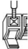
- Close the lever.

Connecting the AM loop antenna
The AM loop antenna is for indoor use only. Set it in the direction and position where you receive the clearest sound. Put it as far as possible away from this unit, TV, speaker cables, and power cords.

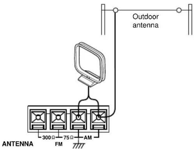
Connecting an AM outdoor antenna
When reception is not satisfactory with the supplied AM loop antenna alone, connection of an outdoor antenna is recommended.
The outdoor antenna will be more effective if it is stretched horizontally above a window or outside.
- Do not remove the AM loop antenna.
- To avoid the risk of lightning and electrical shock, grounding is necessary. Follow item 19 of the "Important Safeguards" on page 3 when you install the outdoor antenna.
Operation
Setting the Clock
The "ACCUCLOCK" features an automatic clock adjusting function automatically sets the clock time on the tuner by means of RDS broadcast signals.
- The "ACCUCLOCK" feature is available only on the European model, and only in areas where RDS broadcasts are available.
- Adjust the clock as explained in "Setting the clock manually" on page 14 if you are using a model U.S. and Canadian models or if you are using the unit in the area where RDS broadcasts are unavailable.
Setting the clock automatically (European models only)
ACCUCLOCK starts operating as soon as the power cord is plugged in. It then searches for an RDS broadcasting station which regularly sends time signals and waits to receive such time information. The tuner should be in STANDBY mode until the clock setting is complete.
The following steps describe how to set the clock automatically:
1. Plug in the power cord.
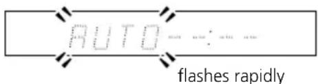
"AUTO" flashes slowly on the time display.

- Once an RDS station that sends time signals is detected, the indicator flashes more rapidly.
-
Once the time signal is received from the RDS station, "CLOCK ADJUSTED" will scroll on the time display.
-
The received time information (the day of the week and the time) appears.

5. The clock starts running.

- It may take about 5 minutes for the time information to be received and displayed.
- After the clock is initially set, it will be adjusted periodically when the tuner unit is in STANDBY mode.
Notes on using the "ACCUCLOCK" function:
- Make sure that your FM antenna has been properly connected as explained on page 10. It is strongly recommended that you install an outdoor FM antenna since the FM indoor antenna may not receive RDS broadcasts well enough to allow ACCUCLOCK to function properly.
- The clock will display the time in a 24 hour cycle. For example, 5:30 pm will be displayed as "17:30". (You can select a 12 hour cycle display setting. For more information, see page 15.)
- If RDS signals cannot be received, no RDS station will be found.
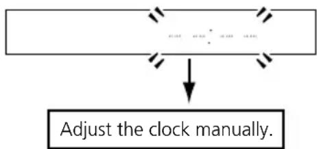
Or if an RDS signal is present but the signal is not strong enough to allow the ACCUCLOCK to automatically set the time, “- -:- -” will lit on the display as shown below. If this occurs, set the clock manually. (See page 14.)
flowchart
graph TD
    A["Start"] --> B{Adjust the clock manually.}
    B --> C["Arrow pointing inward"]
    C --> D["Arrow pointing inward"]
    D --> E["Arrow pointing inward"]
- You may wish to adjust the clock manually because the time information may differ depending on the RDS station detected. If so, follow the manual clock adjustment procedure described on page 14.
- There may be cases in which you can listen to radio broadcasts but cannot use the ACCUCLOCK function.
- Once activated, ACCUCLOCK will remember the RDS station it uses for several weeks even if the power cord of the tuner is unplugged. If you move outside the service area of the memorized RDS station and find out that ACCUCLOCK is not functioning, see "Confirming/changing the RDS Station used by ACCUCLOCK" on page 13 to change the memorized RDS station.

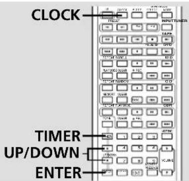
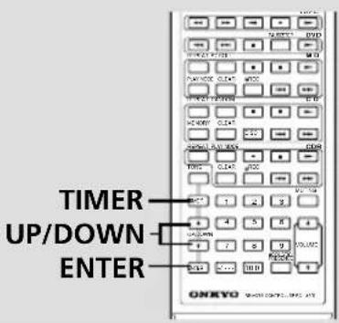
The following procedures are based on the front panel of the T-405TX. However, you can also perform the procedure using the remote controller that comes with Onkyo A-905TX amplifier.
On the remote controller, press the "ENTER" button and "UP/DOWN" button instead of the "MEMORY" button and PRESET◄/► button respectively.
Confirming/changing the RDS station used by ACCUCLOCK
If you wish to know which RDS station has been used to set the clock by ACCUCLOCK, or to use a different RDS station signal to set the clock, follow the steps below:
1 Press the TIMER button repeatedly until "ADJUST" is selected on the display, then press the MEMORY button.

flowchart
graph LR
    A["TIMER"] --> B["ADJUST"]
    C["MEMORY"] --> D["Adaptive Touch"]
"AUTO" or "MANUAL" appears on the display.

The remote controller comes with the Onkyo A-905TX amplifier.
2 If "AUTO" appears on the display, press the MEMORY button. If "MANUAL" appears on the display, press the PRESET ◀ or ▶ button to select "AUTO," then press the MEMORY button.

The example shown above indicates that the ACCUCLOCK function uses the RDS station whose information appears on the display (FM 88.10 MHz). If RDS station signals cannot be received successfully, “-.-” will appear instead of the radio frequency of the station. If you wish to change the selected RDS station or if no RDS station is selected, choose the desired RDS station by using the PRESET◀ or ▶ button, then press the MEMORY button.

The remote controller comes with the Onkyo A-905TX amplifier.
Setting the clock manually
The following procedures are based on the front panel of the T-405TX. However, you can also perform the procedure using the remote controller that comes with Onkyo A-905TX amplifier.
On the remote controller, press the "ENTER" button and "UP/DOWN" button instead of the "MEMORY" button and PRESET◄/► button respectively.
1 Press the TIMER button until "ADJUST" is selected on the display, then press the MEMORY button.
If you do not operate any button for about eight seconds after you press the TIMER button, the system displays the previous indication.

The day of the week will flash on the display.
Non-U.S. and non-Canadian models:
"AUTO" or "MANUAL" appears on the display.
If "MANUAL" appears on the display, press the MEMORY button. If "AUTO" appears on the display, press the PRESET ◀ or ▶ button to select "MANUAL," then press the MEMORY button.
The day of the week will flash on the display.
2 Press the PRESET ◀ or ▶ button until the desired day of the week is selected, then press the MEMORY button.

The time will flash on the display.
The number buttons on the remote controller:
SUN: Sunday MON: Monday
TUE: Tuesday WED: Wednesday
THU: Thursday FRI: Friday
SAT: Saturday
3 Use the PRESET ◀ or ▶ button to set the desired time.

4 Press the MEMORY button.
MEMORY

The clock will start operating.

Tip
Switching between the 24 hour and 12 hour display settings:
- Press the TIMER button repeatedly to display "24H/12H."
- Press the ENTER button.
- Use the UP ▲ or DOWN ▼ button to select 24H (24 hour display) or 12H (12 hour display).
- Press the ENTER button to confirm the setting.
Note
- To use the number buttons instead of the UP ▲ or DOWN ▼ button to set the desired day or the week and time, select the 24-hour display. If you select the 12-hour display, you cannot use the number buttons to set the day and time.
- The ACCUCLOCK function is disabled if you set the clock manually. If you wish to enable the ACCUCLOCK function, refer to the following section.
Clock Call function
You can execute the Clock Call function only by using the remote controller that is supplied with A-905TX amplifier.
1 Press the CLOCK button to display the time, press again to cancel the time display.

Note
If the time has not been set, "ADJUST" will flash on the display.
Enabling the ACCUCLOCK function
If you have set the clock manually (see page 14), the ACCUCLOCK function is automatically disabled. To enable this function, follow the steps below:
1 Press the TIMER button repeatedly until "ADJUST" is selected on the display, then press the MEMORY button.

"MANUAL" appears on the display.
2 Press the PRESET ◀ or ▶ button until "AUTO" appears, then press the MEMORY button.
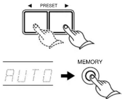
"----" instead of the radio frequency will appear on the display.
3 Press the MEMORY button.
ACCUCLOCK will become active whenever the T-405TX enters STANDBY mode.

Tuning the radio
Make sure that the input selector on the amplifier has been set to TUNER.
1 Press the STANDBY/ON button.
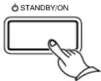
The display changes from clock to frequency (or character) indication.
2 Select FM or AM using the BAND button. (only for U.S. and Canadian models)

Use the TUNING ▼or▲ button to change the frequency.
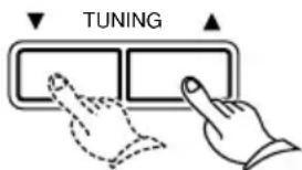
The indoor antenna should be installed on a wall or other surface in the position which gives the best reception. For more information on how to install the antenna, refer to page 10, 11.
Note
AM reception is available on the U.S. and Canadian models.
Display Options:
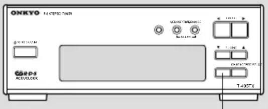
When you are listening to radio broadcasts, the display usually shows the radio frequency of the selected station. You can, however, change to the current time or character information for the selected station. To do so, press the DISPLAY button repeatedly until the desired indication appears.
For more information on how to enter character information, see "Naming a preset station" on page 19.
Using Auto Memory
This function enables you to store the frequencies into memory automatically, without having to go through and store each frequency manually.
1 Hold down the MEMORY button for a few seconds. "AUTO" will start flashing on the display. Keep holding down the button for a few more seconds to start the Auto Memory function.
MEMORY


Hold down
The frequencies are scanned from low to high. Up to 20 FM and 10 AM stations (U.S. and Canadian models) and 20 FM stations (non-U.S. and Canadian models) with the best signal quality are selected, sorted in order from low to high frequency, and stored into the preset memory.
Note
All stations previously stored in memory will be replaced with new Auto Memory stations.

Presetting your favorite stations
You can store your favorite stations in the preset memory. Follow the procedure below:
1 Select FM or AM using the BAND button. (only for U.S. and Canadian models)

Use the TUNING ▼ or ▲ button to select the frequency of your favorite station.

To automatically scan the stations, hold down the TUNING ▼ or ▲ button for more than 0.5 seconds, then release the button.
Scanning will stop when a station is tuned in.
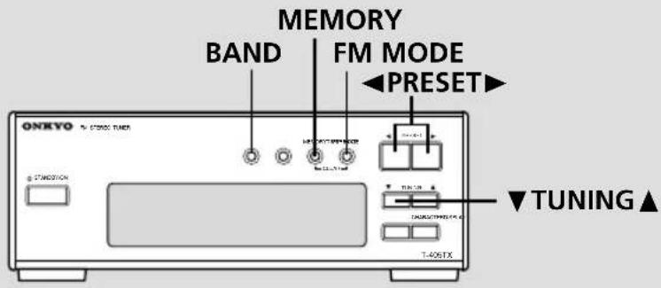
2 Press the MEMORY button.
The MEMORY indicator lights up and “.....” will flash.
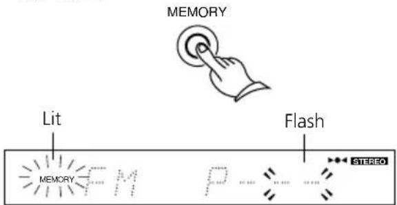
3 While "……" is flashing, use the PRESET ◀ or ▶ button to select the preset number into which to store the station frequency.
The preset number will flash on the display.
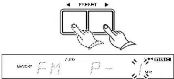
Note
If you select a preset number into which a station has already been programmed, the number will flash rapidly. If you proceed with this number, the original station will be replaced by a new station.
4 While the number is flashing, press the MEMORY button.
The frequency will be stored into the selected preset.

Notes
- Up to 30 stations can be stored in the preset memory.
- If the FM station received is an RDS station that has a PS (Program Service Name), the frequency display will change to the PS display. (Refer to page 22 for more information on the RDS function.) RDS reception is available only on the European models.
Listening to a stereo radio station
When you tune in a stereo FM station, the STEREO indicator lights up if the signal is sufficiently strong. If the signal is weak, you can still listen to the station in mono mode. In this case, tune in as follows.
1 Press the FM MODE button.
The MONO indicator lights up.

2 Select the station you would like to listen to using the TUNING ▼ or ▲ button.

Selecting preset stations
Follow the procedure below to select a preset station stored in memory.
1 Select FM or AM using the BAND button. (only for U.S. and Canadian models) BAND

Use the PRESET ◀ or ▶ button to select the desired preset station.

Clearing preset stations
You can clear preset stations from the preset memory.
1 Select the station as explained in the previous section.
2 Press and hold the MEMORY button and press the FM MODE button within a second.
“……” appears on the display.
MEMORY FM MODE

Note
If you fail to press the FM MODE button while holding down the MEMORY button immediately, the AUTO MEMORY function will start operating.
Naming a preset station

The following 54 characters can be used: — A B C D E F G H I J K L M N O P Q R S T U V W X Y Z " & ' () * + , - , / = ? [ \ ] 10 1 2 3 4 5 6 7 8 9
Naming a preset station
You can name the preset stations so that the name, instead of the frequency, appears on the display when you press the DISPLAY button. (For more information, see "Display options" on page 16.)
Note
You cannot enter characters for an RDS station that has a program service (PS) name, since the PS name has priority over other character information. (For more information on RDS stations, see page 22.)
- RDS reception is available only on the European models.
1 Select the station you wish to name. (See "Selecting preset stations" on page 18.)

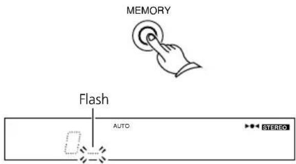
2 Press the CHARACTER button.
The T-405TX enters character input mode, and "....." flashes on the display.

3 Use the PRESET ◀ or ▶ button to select a character.
The character flashes on the display.

4 Press the MEMORY button to store the character.
Flashing “.....” mark appears next to the stored character.
Repeat the steps 3 and 4 to store more characters. You can store up to 8 characters. To enter a space between characters, press the MEMORY button. The bar cursor moves on to the next position.
(continued on the next page)

5 When you finish entering all necessary characters, press the CHARACTER button to complete the operation.
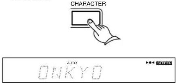
Note
If you have not pressed any button for 16 seconds during the procedure, the operation will complete automatically.
Changing the existing characters
Follow the procedure below to change the existing characters or rename the preset station.
1 Select the station you wish to modify. (See "Selecting preset stations" on page 18.)

2 Press the CHARACTER button.
The T-405TX enters character input mode, and the first character flashes.

3 Press the MEMORY button repeatedly until the character that you want to change flashes.

Note
You can use the TUNING ▼ or ▲ button instead of the MEMORY button.
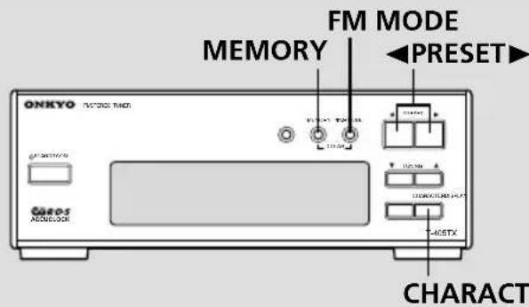
4 Use the PRESET ◀ or ▶ button to change the character.


5 Press the MEMORY button to store the character.

6 Press the CHARACTER button to complete the operation.

Clearing all names stored in memory
Follow the procedure below to delete the name of the selected preset station.
1 Press the CHARACTER button.

2 While holding down the MEMORY button, press the FM MODE button.

The name will be deleted.
Receiving RDS (European models only)
DISPLAY
RDS reception is available only on the European model, and only in areas where RDS broadcasts are available.
What is RDS?
Many FM stations now transmit RDS signals which contain additional information. RDS provides you with various services so that you can choose a station broadcasting your favorite categories of music or other information. The information below is available through the T-405TX.
PS: Program Service Name
RT: Radio Text
Note
If radio signals are weak, RDS may not be received.
Displaying Radio Text (RT)
Radio Text can be displayed as follows.
Note
If the station you are listening to is not an RDS station, no Radio Text will be displayed.
1 Each time you press the DISPLAY button, the display changes as follows.

flowchart
graph TD
    A["Clock"] --> B["Frequency Entered Character or Program service name"]
    B --> C["Radio Text"]

If the current station you are listening to is not an RDS station, only the frequency of the station and the characters (see page 19) appear. (If no characters have been entered, only the frequency information will appear.)
When RT is received, it can sometimes take between a few seconds and 15 seconds (more or less) to display.
Sometimes the following messages will be shown on the display.
WAIT: This message indicates that it requires more time to receive the RT information. When the information is received, the characters will scroll across the display.
NO TEXT: This message appears for three seconds and indicates that even though an RDS station is being received, the signal does not contain RT information.
Using the timer
The T-405TX features a Timer function that enables you to start playing or recording a specified component at a specified time. To use this function, you need to configure a system that includes an ONKYO amplifier A-905TX connected to the T-405TX and other components via RI REMOTE CONTROL jacks. Refer to "System connection for use of Timer function" and "Connecting to other components" on pages 7 through 9 for more information on making the connections.
Buttons and modes for the Timer function
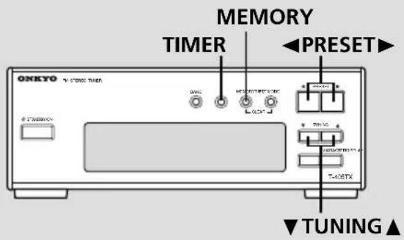
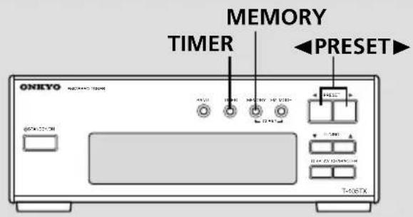
The following buttons and setting modes are used to operate the Timer function. You can use the remote controller (that comes with the ONKYO amplifier A-905TX), as well as the front panel of the T-405TX.

The remote controller comes with the Onkyo A-905TX amplifier.
TIMER button
Use this button to select a timer mode. The timer mode will change each time you press this button.
PRESET ◀/▶ buttons (T-405TX), or UP/DOWN (▲/▼) buttons (Remote controller)
Use these buttons to select the details of the mode or to change values.
MEMORY button (T-405TX), or ENTER button (Remote controller)
Use this button to enter the selected mode or numbers.
Timer setting modes:
- WEEKDAY: This mode enables you to listen to a specified component at a designated time on weekdays. You can change the day of the week in DAY SET mode.
- WEEKEND: This mode enables you to listen to a specified component at a designated time on weekends. You can change the day of the week in DAY SET mode. You can define the same day of the week as both WEEKDAY and WEEKEND. To set two programs for one day, specify the same day of the week as WEEKDAY and WEEKEND and set the time for each program.
- REC: This mode enables you to record your favorite broadcasting program(s) starting at a designated time. You can select from NEXT, the day of the week, and EVERYDAY. Except for EVERYDAY, the unit performs the timer recording once at the designated time.
- DAY SET: This mode enables you to change the day setting (definition) of WEEKDAY or WEEKEND.
- ADJUST: This mode enables you to set and adjust the clock.
If you have adjusted the clock, you do not need to set it again.
The following sections (page 24–28) describe operations using the front panel of the T-405TX. As mentioned above, however, you can also perform the following operations from the remote controller that comes with the Onkyo A-905TX amplifier.
On the remote controller, press the ENTER button and UP/DOWN (▲/▼) buttons instead of the MEMORY button and PRESET ◀/▶ buttons respectively.
The remote controller comes with the Onkyo A-905TX amplifier.
Changing the WEEKDAY and WEEKEND settings
You can define or change which day is WEEKDAY or WEEKEND. You can also define the day as both WEEKDAY and WEEKEND in order to program two timer settings on the same day.
The initial factory settings are:
WEEKDAY : Monday – Friday
WEEKEND : Saturday and Sunday

1 Press the TIMER button repeatedly until "DAY SET" appears on the display, then press the MEMORY button.

2 Press the PRESET ◀ or ▶ button to select "WEEKEND" or "WEEKDAY".
"END" or "DAY" flashes.

3 Press the MEMORY button.
MEMORY

The current WEEKDAY or WEEKEND setting will be displayed.
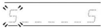
4 Press the MEMORY button repeatedly until the desired day of the week flashes.
MEMORY


S (Sunday) T (Thursday)
M (Monday) F (Friday)
T (Tuesday) S (Saturday)
W (Wednesday)
To move the cursor to the left, press the ▼TUNING button. To move the cursor to the right, press the TUNING▲ button.
5 Press the PRESET ◀ or ▶ button to display the desired day of the week.

Pressing the PRESET ◀ or ▶ button repeatedly toggles between the day indication and the bar cursor (.....).
6 Press the MEMORY button to confirm the selection.
When you press the MEMORY button while the character or bar cursor at the right end is flashing, the unit completes the setting.
Programming to play at a specified time
Before using the timer for listening to or recording broadcast programs, you need to store the preset stations. (Refer to "Receiving stations" on page 16, 17 for information how to preset stations.)
Notes
- The clock of the tuner must be set correctly before programming the timer.
- Make sure that the specified source component is connected to the amplifier, and that the CD, MD, or cassette tape has been inserted into the appropriate component.
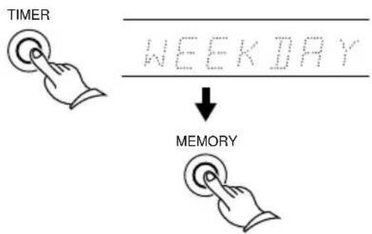
1 Press the TIMER button repeatedly until "WEEKDAY" or "WEEKEND" is displayed, and press the MEMORY button.
flowchart
graph TD
    A["TIMER"] --> B["WEEKDAY"]
    B --> C["↓"]
    C --> D["MEMORY"]
2 Press the PRESET ◀ or ▶ button to set the ON time, and press the MEMORY button.

- When you store the ON time, the display automatically indicates that the OFF time is one hour after the ON time you specified.
3 Press the PRESET ◀ or ▶ button to select the OFF time, and press the MEMORY button.


The remote controller comes with the Onkyo A-905TX amplifier.
4 Press the PRESET ◀ or ▶ button to select the source (FM/AM/CD/MD/TAPE/LINE/DVD/CDR/PC), and press the MEMORY button.

If you select "FM" or "AM", press the PRESET
◀ or ▶ button again to select the preset number and press the MEMORY button.
- AM reception is available only on the U.S. and Canadian models.
5 Press the STANDBY/ON button on the Amplifier A-905TX to set the STANDBY mode.


Notes
- After setting the timer, be sure to set the amplifier in STANDBY mode. If the amplifier is not in STANDBY mode, the timer will not work.
- Make sure that the POWER switch on the A-905TX Amplifier is set to ON.
Programming to record at a specified time
REC mode of the Timer function enables you to record a specified source at a specified time.
Notes
- The clock of the tuner must be set correctly before programming the timer.
- Make sure that the specified source component is connected to the amplifier, and that the CD, MD, or cassette tape has been inserted into the appropriate component.
- To perform timer recording to a tape, you need to use a cassette tape deck that features the RI mark, such as the K-505TX.
- To perform timer recording to a mini disc, you need to use an MD recorder that features the RI mark, such as the MD-105TX.
1 Press the TIMER button repeatedly until "REC" appears on the display, then press the MEMORY button.

2 Press the PRESET ◀ or ▶ button to select NEXT, the day of the week or EVERYDAY for recording, then press the MEMORY button.
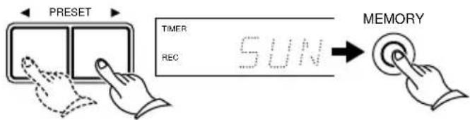
You can select "NEXT" instead of the day of the week. If you do so, recording will start at the next occurrence of the indicated time. If you select "EVERYDAY," recording will start at the designated time everyday.
3 Press the PRESET ◀ or ▶ button to set the ON time, and press the MEMORY button.

- When you store the ON time, the display automatically indicates that the OFF time is one hour after the ON time you specified.
4 Press the PRESET ◀ or ▶ button to set the OFF time, then press the MEMORY button.

5 Press the PRESET ◀ or ▶ button to select the source (FM/AM/LINE/DVD), and press the MEMORY button.

If you select "FM" or "AM", press the PRESET
◀ or ▶ buttons again to select the preset number, then press the MEMORY button.
- AM reception is available only on the U.S. and Canadian models.
6 Press the PRESET ◀ or ▶ button to select the recording component (MD REC, TAPE REC, or MD/TAPE REC), and press the MEMORY button.

- When you record analog FM or AM signals to an MD recorder, be sure to use Analog In on the MD recorder.

The remote controller comes with the Onkyo A-905TX amplifier.
7 Press the STANDBY/ON button on the Amplifier A-905TX to set the STANDBY mode.


Notes
- Since muting is automatically turned on when the timer is used to record, the sound cannot be heard during recording. To monitor recording, press the MUTING button on the remote controller to cancel muting.
- Timer recording (except for the "EVERYDAY" timer recording) is activated once. After recording, the REC mode setting will be cancelled.
• After setting the timer, be sure to set the amplifier in STANDBY mode. If the amplifier is not in STANDBY mode, the timer will not work. - Make sure that the POWER switch on the A-905TX Amplifier is set to ON.
Switching the timer ON/OFF
You can switch the timer ON/OFF to cancel the timer setting, to enable the timer again, or to perform timer recording again.
When the Timer function is enabled, the selected timer mode such as "WEEKDAY", "WEEKEND", and "REC" appears in the upper left corner of the display.
Note
To switch the timer ON, first you need to program the time value.
1 Press the TIMER button repeatedly until the timer mode (WEEKDAY, WEEKEND or REC) that you wish to enable or disable appears on the upper left corner of the display.
TIMER

NEEKDAY
2 Press the PRESET ◀ or ▶ button to switch the selected mode ON or OFF.


3 Press the MEMORY button to confirm the selection.
MEMORY

The remote controller comes with the Onkyo A-905TX amplifier.
Sleep function
The Sleep function can be performed only by using remote controller that comes with the amplifier A-905TX.
The SLEEP timer automatically sets the entire system to standby mode after a specified period of time.
1 Start playing something you would like to listen to.
(CD, tape, MD or radio broadcast).
2 Press the SLEEP button repeatedly to set the desired sleep time.
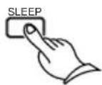

The time value will decrease from 90 minutes to 10 minutes in steps of 10 minutes.
After a specified period of time, the power will be switched off automatically.
- To check the remaining time while the SLEEP function is active, press the SLEEP button.
Cancelling the SLEEP setting
Press the SLEEP button repeatedly until the SLEEP indicator on the display disappears.
Notes for timer setting
- Make sure that the clock has been set correctly before setting the timer.
• After setting the timer, be sure to set the apmlifier in standby mode. If the amplifier is not in standby mode, the timer will not work.
- When the power is turned on by one of the timer mode settings, the other timer modes may not be activated at their ON time. The power will be switched off by the first timer mode at its OFF time. (See the figure below.)
- If you press the SLEEP button during timer play or timer recording, the power will be switched off at the SLEEP timer's OFF time.
- If more than two timer mode settings are made at the same time, the "WEEKDAY" setting has the priority over the "WEEKEND" setting. The "REC" mode setting has no priority.
- The timer recording setting will be cancelled if the recording does not start at the ON time (for example, if the power is already on).

line
| Time | Event | Value | |---|---|---| | 9:00 | WEEKDAY | activate | | 10:00 | REC | not activate | | 11:00 | WEEKEND | activate | | 12:00 | WEEKEND | activate | ↑ ON ↑ OFF ↑ ON ↑ OFFOther Information Troubleshooting
| Symptom | Cause | Remedy |
| No power. | Power cord is disconnected. | Connect power cord. |
| AM stations cannot be received. | AM loop antenna is not attached. | Connect the supplied AM loop antenna to the AM antenna terminals. |
| Buzzing noise on AM (particularly conspicuous at night or with weak stations). | Noise from electrical apparatus such as fluorescent lamp. | Move the AM loop antenna to different position.Set up an outdoor AM antenna. |
| High-pitched noise or buzzing noise on AM. | Noise from TV set. | Place the AM loop antenna as far as possible from the TV.Move unit away from TV set. |
| Crackling noise on AM, FM. | Noise caused by turning a fluorescent lamp on and off.Noise from automobile ignition. | Move the antenna as far away as possible from the fluorescent lamp.Install an outdoor FM antenna as far away as possible from the road. |
| Tuning indicators and stereo indicator light but sound is distorted and separation is bad. | Station is too strong.Multiple reflection of the radio waves because of tall buildings or mountains. | Change to FM indoor antenna.Use antenna that has better directivity and select a point with the least distortion. |
| Tuning indicators and stereo indicator flicker and hiss is heard on FM. | Station is too weak.Stereo FM broadcasts cover only about half the distance of an ordinary broadcast. | Install an outdoor FM antenna.Change the position or direction of the outdoor antenna.Switch to mono reception. (Even stereo broadcasts will be heard in mono.) |
| No station or undesired station is recalled when a Preset button is pressed. | The power cord has been unplugged for a long time. | The memory contents are lost if the power is not turned on and off a few times each month. Store all stations in the memory again and remember to turn the power on and off a few times each month. |
| The RDS function does not work. | The station is not an RDS station.The reception station signal is too weak.Too much interference. | Receive an RDS station.Install an outdoor FM antenna.Change the position or direction of the outdoor antenna.Move the antenna as far away as possible from fluorescent lamps.Install an outdoor FM antenna. |
| ACCUCLOCK function does not work. | The station is not an RDS station, or received signal is too weak.RDS broadcasts cannot be received. | See the remedies for the RDS function problem above.Set and adjust according to instructions above. |
- Excessive electrical interference may temporarily render this system's sensitive microcomputer inoperable. If this happens, unplug the system for at least five seconds.
Front panel
For more information about buttons, turn to the page number in the brackets [].
![PRESET ◀/► buttons [13, 14, 15, 17~19, 21, 23~28] CLEAR or FM MODE button [18, 21] MEMORY button [13~21, 23~28] TIMER button [13~15, 23~28] BAND button [16~18] (U.S. and Canadian models only) STANDBY/ON button [16] ONIKYO FM STERESTUNER STANDBY/ON BAND MEMORY/TAMM MODE CLEAR TUNING CHARACTERDISPLAY T-405TX DISPLAY button [16, 22] CHARACTER button [19~21] TUNING ▼/▲ buttons [16~18] U.S. and Canadian model's front panel shown](/content/2026/05/884741/images/64432a56383b6c2364be147d190929518c57f525350888904b327dbddb2628c6.jpg)
Display

Specifications
FM
Tuning Range:
87.90 - 107.90 MHz, 200 kHz steps
(U.S. & Canadian models)
87.50 - 108.00 MHz, 50 kHz steps
(Ohter area models)
Usable Sensitivity:
Mono : 12.8 dBf 1.2 μV, 75 Ohms IHF
Stereo: 19.2 dBf 2.5 μV, 75 Ohms IHF
50dB Quieting Sensitivity:
Mono : 18.0 dBf 2.2 μV, 75 Ohms
Stereo: 38.0 dBf 22 μV, 75 Ohms
Capture Ratio : 1.5 dB
Image Rejection Ratio : 85 dB
IF Rejection Ratio : 90 dB
Signal-to-Noise Ratio : Mono: 73 dB IHF
Stereo: 66 dB IHF
Selectivity : 50 dB DIN (±300 kHz, 40 kHz dev.)
AM Suppression Ratio : 50 dB
Total Harmonic Distortion : Mono: 0.5%
Stereo: 0.8%
Frequency Response : 30 - 15,000 Hz (±1.5 dB)
Stereo Separation : 40 dB at 1 kHz
30 dB at 70 - 10,000 Hz
Output Level : 0.5 V (U.S.& Canadian models)
0.75 V (Other area models)
Muting Level : 17.2 dBf 2.0 μV, 75 Ohms
AM
Tuning Range :
530 - 1,710 kHz, 10 kHz steps
Usable Sensitivity : 30 μV
Image Rejection Ratio : 30 dB
IF Rejection Ratio : 40 dB
Signal-to-Noise Ratio : 40 dB
Total Harmonic Distortion : 0.8%
Output Level: 0.15 V
General
Power Supply :
AC 120 V, 60 Hz
AC 230-240 V, 50 Hz
Power Consumption : 9 W
AM reception is available only on the U.S. and Canadian models.
Specifications and external appearance are subject to change without notice as a result of product improvement.
ONKYO CORPORATION
Sales & Product Planning Div.: 2-1, Nisshin-cho, Neyagawa-shi, OSAKA 572-8540, JAPAN
Tel: 072-831-8111 Fax: 072-833-5222 http://www.onkyo-intl.com
18 Park Way, Upper Saddle River, N.J. 07458, U.S.A.
Tel: 201-785-2600 Fax: 201-785-2650 http://www.onkyousa.com
ONKYO EUROPE ELECTRONICS GmbH
Liegnitzerstrasse 6, 82194 Groebenzell, GERMANY
Tel: +49-8142-4401-0 Fax: +49-8142-4401-555 http://www.onkyo.net
ONKYO CHINA LIMITED
Units 2102-2107, Metroplaza Tower I, 223 Hing Fong Road, Kwai Chung,
N.T., HONG KONG Tel: 852-2429-3118 Fax: 852-2428-9039


- FM Stereo Tuner T-405TX
- Before using
- Thank you for purchasing ...
- Main Features
- WARNING:
- CAUTION:
- WARNING
- AVIS
- Important Safeguards
- Precautions
- Warranty Claim
- Care
- Power
- For British model
- IMPORTANT
- For U.S. model
- Note to CATV system installer:
- FCC Information for User
- NOTE:
- For Canadian model
- Operation
- Other Information
- Supplied accessories
- Declaration of Conformity
- Memory Preservation
- Connections
- Connecting to the ONKYO Separate Collection Series Components
- - Auto Power On
- - Direct Change
- - Remote Control Operation
- - Program Timer
- - Sleep Timer
- - CD Dubbing
- • CD/MD Synchro Recording
- - Dubbing a specific track from CD
- System connection for use of Timer function
- Notes
- Using the remote controller
- Connecting to other components
- Before connecting
- Connecting the Connector
- Note
- Antenna connections
- Connecting the FM antenna
- Connecting the antenna cable
- FM indoor antenna
- FM outdoor antenna
- Connecting the AM antenna (U.S. and Canadian models only)
- Assembling the AM loop antenna
- Connecting the AM loop antenna
- Connecting an AM outdoor antenna
- Setting the Clock
- Setting the clock automatically (European models only)
- Plug in the power cord.
- The clock starts running.
- Notes on using the "ACCUCLOCK" function:
- Confirming/changing the RDS station used by ACCUCLOCK
- Setting the clock manually
- Press the TIMER button until "ADJUST" is selected on the display, then press the MEMORY button.
- Non-U.S. and non-Canadian models:
- Press the PRESET ◀ or ▶ button until the desired day of the week is selected, then press the MEMORY button.
- Use the PRESET ◀ or ▶ button to set the desired time.
- Press the MEMORY button.
- Tip
- Clock Call function
- Press the CLOCK button to display the time, press again to cancel the time display.
- Enabling the ACCUCLOCK function
- Press the TIMER button repeatedly until "ADJUST" is selected on the display, then press the MEMORY button.
- Press the PRESET ◀ or ▶ button until "AUTO" appears, then press the MEMORY button.
- Press the MEMORY button.
- Tuning the radio
- Press the STANDBY/ON button.
- Select FM or AM using the BAND button. (only for U.S. and Canadian models)
- Display Options:
- Using Auto Memory
- Hold down the MEMORY button for a few seconds. "AUTO" will start flashing on the display. Keep holding down the button for a few more seconds to start the Auto Memory function.
- Presetting your favorite stations
- Select FM or AM using the BAND button. (only for U.S. and Canadian models)
- Press the MEMORY button.
- While "……" is flashing, use the PRESET ◀ or ▶ button to select the preset number into which to store the station frequency.
- While the number is flashing, press the MEMORY button.
- Listening to a stereo radio station
- Press the FM MODE button.
- Select the station you would like to listen to using the TUNING ▼ or ▲ button.
- Selecting preset stations
- Select FM or AM using the BAND button. (only for U.S. and Canadian models) BAND
- Clearing preset stations
- Select the station as explained in the previous section.
- Press and hold the MEMORY button and press the FM MODE button within a second.
- Naming a preset station
- Changing the existing characters
- Press the CHARACTER button.
- Receiving RDS (European models only)
- What is RDS?
- Displaying Radio Text (RT)
- Each time you press the DISPLAY button, the display changes as follows.
- Using the timer
- Buttons and modes for the Timer function
- TIMER button
- PRESET ◀/▶ buttons (T-405TX), or UP/DOWN (▲/▼) buttons (Remote controller)
- MEMORY button (T-405TX), or ENTER button (Remote controller)
- Timer setting modes:
- Changing the WEEKDAY and WEEKEND settings
- Programming to play at a specified time
- Press the PRESET ◀ or ▶ button to select the source (FM/AM/CD/MD/TAPE/LINE/DVD/CDR/PC), and press the MEMORY button.
- Press the STANDBY/ON button on the Amplifier A-905TX to set the STANDBY mode.
- Programming to record at a specified time
- Press the TIMER button repeatedly until "REC" appears on the display, then press the MEMORY button.
- Press the PRESET ◀ or ▶ button to select NEXT, the day of the week or EVERYDAY for recording, then press the MEMORY button.
- Press the PRESET ◀ or ▶ button to set the ON time, and press the MEMORY button.
- Press the PRESET ◀ or ▶ button to set the OFF time, then press the MEMORY button.
- Press the PRESET ◀ or ▶ button to select the source (FM/AM/LINE/DVD), and press the MEMORY button.
- Press the PRESET ◀ or ▶ button to select the recording component (MD REC, TAPE REC, or MD/TAPE REC), and press the MEMORY button.
- Press the STANDBY/ON button on the Amplifier A-905TX to set the STANDBY mode.
- Switching the timer ON/OFF
- Sleep function
- Start playing something you would like to listen to.
- Press the SLEEP button repeatedly to set the desired sleep time.
- Cancelling the SLEEP setting
- Notes for timer setting
- Other Information Troubleshooting
- Front panel
- Specifications
- FM
- AM
- General
- ONKYO CORPORATION
- ONKYO EUROPE ELECTRONICS GmbH
- ONKYO CHINA LIMITED
Brand : ONKYO
Model : T-405TX
Category : Audio tuner