
VOCE AV uno - Receiver AUDISON - Free user manual and instructions
Find the device manual for free VOCE AV uno AUDISON in PDF.


| Product Type | Mono Amplifier |
| Amplifier Class | AB/D Hybrid (POD - Power On Demand) |
| Dimensions (W x L x H) | 8.66" x 18.50" x 2.28" (220 x 470 x 58 mm) |
| Weight | 15.87 lb (7.2 kg) |
| Power Supply Voltage | 11 – 15 V DC |
| Idling Current | 2 A (off: 0.02 mA) |
| Max Musical Power Consumption (14.4 V) | 120 A |
| RMS Power (12 V, 4 Ω, 0.3% THD) | 700 W x 1 |
| RMS Power (14.4 V, 1% THD) | 700 W x 1 (4 Ω), 1300 W x 1 (2 Ω), 1700 W x 1 (1 Ω) |
| Total Harmonic Distortion (1 kHz, 4 Ω) | 0.04% |
| Bandwidth (-3 dB) | 7 – 20,000 Hz |
| Signal-to-Noise Ratio (A-weighted, 1 V) | 95 dBA |
| Damping Factor (1 kHz, 4 Ω) | 160 |
| Input Sensitivity (RCA) | 0.3 – 5 V RMS |
| Input Impedance (RCA) | 15 kΩ |
| High-Level Input Sensitivity (Speaker In) | 1.4 – 24 V RMS |
| High-Level Input Impedance | 5 kΩ |
| Minimum Load Impedance | 1 Ω |
| Low-Pass Filter | 50 – 150 Hz, 24 dB/oct |
| Subsonic Filter | 20 – 50 Hz, 24 dB/oct |
| Bass Boost | 0 – 6 dB at 50/70/90 Hz |
| Phase Adjustment | Normal / Reverse (180°) |
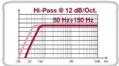
| Pre-Out Hi-Pass Filter | 50 – 150 Hz, 12 dB/oct |
| Inputs | RCA (Pre In) / Speaker In (High-Level) |
| Outputs | Speaker A, Speaker B (Mono) / Pre Out L-R |
| Remote Control | Remote IN/OUT, VCRA Sub Volume (optional) |
| Fuse | 100 A (strip type) |
| Digital Interface (Optional) | AV bit IN with AD Link / AC Link |
| Recommended Fuse (Battery) | 150 A (50% higher than amplifier fuse) |
Frequently Asked Questions - VOCE AV uno AUDISON
User questions about VOCE AV uno AUDISON
0 question about this device. Answer the ones you know or ask your own.
Ask a new question about this device
Download the instructions for your Receiver in PDF format for free! Find your manual VOCE AV uno - AUDISON and take your electronic device back in hand. On this page are published all the documents necessary for the use of your device. VOCE AV uno by AUDISON.
USER MANUAL VOCE AV uno AUDISON
2.1 Available accessories ....04
3. SAFE SOUND 05
4. PRECAUTIONS 06
5. INSTALLATION 07
6. REAR PANEL 08
6.1 How to connect power cables 08
6.2 How to replace the fuse 09
6.3 How to connect the remote switch 09
6.4 Remote switching via SPK IN 10
6.5 How to connect the Sub remote volume control 10
7. FRONT PANEL 11
7.1 Input controls 12
7.2 How to connect a source via PRE inputs 13
7.3 How to connect a source via the Speaker IN High-Level input 13
8. INPUT CONTROLS 14
8.1 Control panel: switches and adjustments 14
8.2 Amplifier settings....15
8.2.1 Full Range 15
8.2.2 Lo Pass 15
8.2.3 Subsonic 16
8.2.4 Phase 16
8.2.5 Boost....16
8.3 Example: PRE INPUT / PRE OUTPUT / DOUBLE SUBWOOFER 17
8.4 Example: DUAL MONO PRE INPUT / PRE OUT 18
8.5 Esempio: SPEAKER INPUT / PRE OUT DOUBLE SUBWOOFER 19
9. ACCESSORIES: AV bit IN 21
9.1 How to insert AV bit IN 22
9.2 Front panel 23
9.3 Control panel display 24
9.4 How to connect the amplifier equipped with AV bit IN to the system 25
9.5 How to configure AV bit IN 26
9.6 Full DA Example: Front + Rear + Sub with Audison bit Ten D processor 27
9.7 Full DA Example: Woofer + Tweeter + Sub with Audison bit Ten D processor 28
9.8 Full DA Example: Front + Rear + Sub with Audison bit One processor....29
9.9 Full DA Example: Woofer + Tweeter + Sub with Audison bit One processor....30
10. TECHNICAL SPECIFICATIONS ....31
1. INTRODUCTION
Coming directly from the know-how of the exceptional Thesis line, Voce components take the experience of listening in the car to a new level of excellence.
Project innovation, advanced design, benchmark performance; the synthesis of consolidated know-how applied to car audio systems. The Voce project was born to make Thesis sound quality available to a wider - but no less demanding - audience. The development of these components took advantage of the major innovations introduced while designing the Thesis line: analog and digital technologies combined using different classes of configuration for amplifiers, reduction of the main sources of non-linear distortion, linearization of acoustic and electric loads, control of cone and diaphragm resonance for speakers. To achieve these goals it was necessary to develop new circuit solutions, increase heat capacity, design new moulds for baskets and diaphragms and define new assembly procedures and quality control.
A delicate balance of analysis and refinement led us to results exceeding our expectations and set a new benchmark for the category.
THE AV uno AMPLIFIER PROJECT
AV uno is an amplifier featuring an innovative circuitry called POD (Power On Demand). It allows to combine the plus points, in terms of audio quality and robustness, of the AB Class traditional amplifiers with the efficiency of the D Class amplifiers.
AV uno is a mono amplifier designed to drive the subwoofer but also suitable for high power Dual Mono systems. Power, control and outstanding final stages are capable to unbelievable bass and extraordinary musical quality on the whole frequency range. AV uno also allows you to replace the analog input board with the digital one (AV bit IN).
2. PACKAGING CONTENT
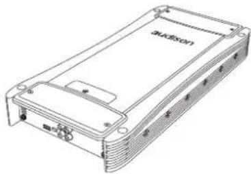
- AV uno amplifier
- Quick start guide
- Warranty
- nr.4 3,9 x 25mm / 0,15" x 0,99 self-tapping cross-headed fixing screws
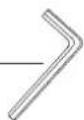
- N. 1 Allen wrench 0,118"
- nr.1 100A AFS spare fuse
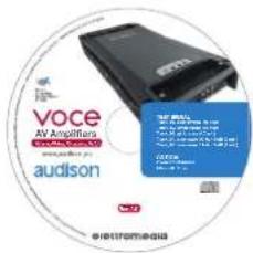
- CD ROM with: This Owner's manual (.pdf format) Test tracks
2.1 AVAILABLE ACCESSORIES (not provided)
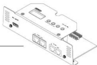
- AV bit IN: AV amplifiers digital interface
- VCRA: SUB volume remote control
natural_image
Line drawing of a rectangular electronic device with ports and connectors (no text or symbols visible)



natural_image
Line drawing of an electronic device rear panel with ports and connectors (no text or symbols)
3. SAFE SOUND
AUDISON AMPLIFIERS CAN BE PART OF A HIGH POWER AUDIO SYSTEM THAT CAN GENERATE VERY HIGH UNDISTORTED SOUND PRESSURE LEVELS. PLEASE REMEMBER THAT LONG EXPOSURE TO AN EXCESSIVELY HIGH SOUND PRESSURE LEVEL MAY DAMAGE YOUR HEARING; THEREFORE, PLEASE USE COMMON SENSE AND PRACTICE SAFE SOUND.

Safety must be at the forefront while driving. The listening volume should never obscure the noise coming from the outside of your vehicle; you should be able to hear the sounds generated by your vehicle in order to promptly face any emergency situation.
To achieve the best possible performance from your new components, we recommend you follow the instructions in this manual carefully. In order to design and create top level car hi-fi systems you need to understand automobile mechanical and electrical issues very well; if you think you lack the required knowledge or the proper tools, please consult with a specialized installer.
A professional installation will ensure your system delivers all the performance you have paid for, without affecting the safety and reliability of your vehicle.
This manual has been designed to provide you with the basic instructions required to install and use this product. However, the range of possible applications is very wide; to obtain further information, please contact your authorized Audison dealer or Audison service center.
You can also send an e-mail directly to the following addresses:
- This symbol indicates that you have to pay attention to these instructions. Disregarding them might cause accidental harms or damage your amplifier.
- Before installing the amplifier, make sure you carefully read and understand all instructions.
- The vehicle electric system must have 12V DC voltage with negative to ground. Make sure your car has it in order to avoid any damages to your amplifier and to the vehicle.
- Pre-plan the configuration of your new amplifier and the best wiring routes to ease installation.
• Always wear protective eyewear when using tools that may generate splinters. -
During installation, keep the amplifier in its packing as long as possible; this will protect it from damages.
-
Secure all auxiliary devices you built to install the components to the vehicle structure through brackets, screws, nuts and bolts; this insures stability and safety while driving.
- The amplifier detachment while driving can damage the people in the vehicle and other cars. Secure the amplifier at best, paying utmost attention if installation is inside the passenger's compartment. Do not carry out any installation inside the engine compartment.
- Before installing the amplifier, turn off the source and all other electronic devices in the audio system for preventing any damages.
- Make sure the location you chose for the components does not affect the correct functioning of the vehicle mechanic and electric devices.
- Do not run the cables or install the amplifier next to electronic gearcases.
- Use extreme caution when cutting or drilling the car plate, checking there are no electrical wiring or structural element underneath.
- Before connecting the power cable to the amplifier, disconnect the negative lead (-) from the car battery.
- Make sure power cable is not short circuited during installation and connection.
- Power cable must have mechanically resistant and self-extinguishing insulation. Its section have a size corresponding with what is suggested in this manual. Avoid to run it over or through sharp edges or close to moving mechanical devices. Make sure it is well fixed all along its length. Block positive and negative cables just close to the amplifier respective power supply terminal blocks through a clamping screw.
- Use rubber grommets to protect the wire if it runs in a hole of the plate or proper materials if it is close to heat-generating parts.
- To ground the device (-) in the right way, use a screw in the vehicle chassis; scrape all paint or grease from the metal if necessary, checking with a tester that there is continuity between the battery negative terminal (-) and the fixing point. If possible, connect all components to the same ground point; this solution rejects most noise.
- Route all signal cables away from power cables.
- Never run cables outside the vehicle; you would not be protected against wear and in case of accidents.
- When installing speakers and the cables that connect them, make sure that non-insulated parts never touch, even occasionally, the vehicle cutting parts. If they do, the amplifier protection is activated.
• To prevent all problems, use very good quality cables, connectors and accessories, choosing them in Connection catalogue. - When installation is over, and before plugging the main power supply fuse, check the system wiring and make sure all connections were done in the right way.
- Power amplifiers put an increased load on the battery and on its charging system. We recommend checking your alternator and battery condition to ensure they can handle the increased consumption. Standard electrical systems which are in good condition should be able to stand this extra load without problems but we recommend the use of an energy storage capacitor and/or a battery for high level audio systems.
- Put a fuse and its insulated fuse holder 40 cm max. far from the battery positive terminal; connect one end of the power cable to it after connecting the other end to the amplifier. The fuse value must be 50% higher than the amplifier built-in one. In case the cable supplies several amplifiers, the fuse value will have to be 50% higher than the sum of the values of all other fuses in the amplifiers.
- There must be good air circulation where the amplifier is installed; this area must not be affected by humidity, rain, external deposits or parts coming from the vehicle mechanical devices. Do not hinder in any way the cooling of the amplifier side fins
• Install the amplifier in the vehicle parts where temperature is between 0°C (32°F) and 55°C (131°F).
WARNING. When working in demanding conditions, the amplifier can reach temperatures of around 80 - 90°C (176 ÷ 194°F). Make sure it is not dangerously hot before touching it.
- Periodically clean the amplifier without using aggressive solvents that might damage it. Dampen a piece of cloth with water and soap, wring it and clean the amplifier. Then use a piece of cloth dampened with water only; eventually clean the amplifier with a dry piece of cloth.
- Remove dust and solid deposits from the heat sink side fins. Don't use compressed air on the amplifier since it would push solid parts in the amplifiers. If necessary, please contact a specialised service centre for internal cleaning. Cooling system obstruction makes the amplifier go in safety mode.
5. INSTALLATION
External size

Mounting size

How to mount
self-tapping screw 3,9 x 25 mm / 0,15" x 0,99

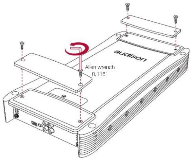
How to remove the panel
- REAR PANEL

- Protection fuse: 100 A;
- Power (Ground): Terminal block for the amplifier power supply negative pole connection. Insert here the battery negative cable or wire connected to the vehicle chassis. The plug accepts cables up to 2 A.W.G. For better current transfer it is recommended to use cables with the maximum cross-section possible and in any case of the same cross-section of the cable connected to the positive pole;
- Power (11-15V DC): Terminal block for the amplifier 11÷15V DC power supply positive pole connection. Insert here the battery positive cable. The plug accepts cables up to 2 A.W.G. For better current transfer it is recommended to use cables with the maximum cross-section possible and in any case of the same cross-section of the cable connected to the negative pole;
- +CAP: Terminal for connecting the positive pole of an external capacitor.
- Speaker A OUT: A Speaker output + and - power terminal; signal in mono.
- Speaker B OUT: B Speaker output + and - power terminal; signal in mono.
- Remote Sub Control: inputs for remote control of the VCRA Sub volume control (optional).
- Remote IN/OUT:
REMOTE IN: terminal for the remote cable coming from the device which turns on the amplifier. REMOTE OUT: terminal to launch the remote voltage to turn on other amplifier. The output voltage is 12V 50 mA. On this terminal the start-up control will be available for other devices even if Rem In is not in use and SPKs IN (see 7.2) are in use for starting-up.
6.1 HOW TO CONNECT POWER CABLES

6.2 HOW TO REPLACE THE FUSE
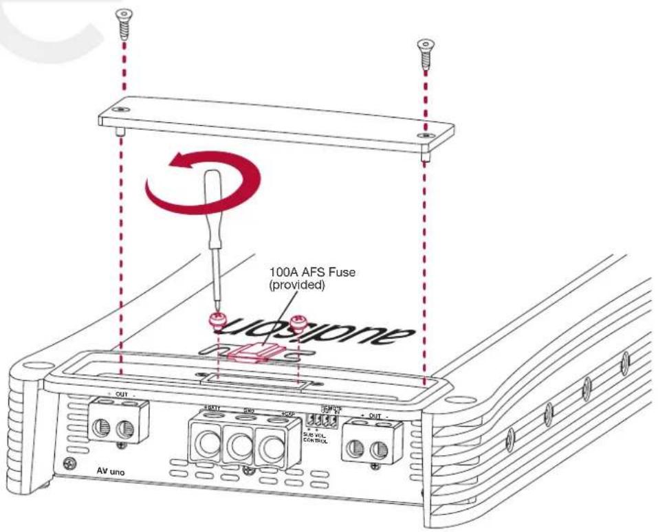
6.3 HOW TO CONNECT THE REMOTE SWITCH

6.4 REMOTE SWITCHING VIA SPK IN

SWITCH ON enables turning the product on from the SPEAKER IN CH A inputs
6.5 HOW TO CONNECT THE SUB REMOTE VOLUME CONTROL

VCRA Sub remote control (optional)
7. FRONT PANEL

- INPUT (0.3 - 5V): Left and Right analog inputs.
- PREOUT L - R: This jack provides Left and Right INPUT channel pre-amplified outputs to drive a separate amplifier. These output signals are filtered by the Hi-Pass adjustable controls section.
- SPK IN (1.2V - 20V): High-level Left and Right analog inputs.
- ART (ON -OFF): If the source does not feature a 12V DC REMOTE OUT, set the ART switch to ON to turn on the amplifier plugging the cables to the SPK IN signal inputs. If the source features a 12V DC REMOTE OUT, set the ART switch to OFF.
7.1 INPUT CONTROLS
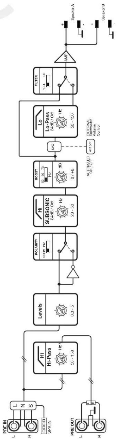
flowchart
graph LR
    A["PRE IN"] --> B["L N S"]
    C["PRE OUT"] --> D["R R"]
    B --> E["Hi - Hi-Pass 50 - 150 Hz"]
    D --> F["Levels 0.3 - 5"]
    E --> G["Polarity NORM INV"]
    F --> H["Polarity 20 - 50 Hz"]
    G --> I["Subsonic 24dB / Oct"]
    H --> J["Subsonic 50 - 60 Hz"]
    I --> K["Boost 0 / +6 dB"]
    J --> L["Boost 70 Hz"]
    K --> M["svc"]
    L --> M
    M --> N["Lo - Lo-Pass 24dB / Oct"]
    N --> O["FILTER FULL LO"]
    O --> P["AMP"]
    P --> Q["Speaker A"]
    P --> R["Speaker B"]
    N --> S["ext.pot"]
    S --> T["EXTERNAL Subwoofer Volume Control"]
LNS= Line Noise Suppressor
SPK IN= Speakers IN (Hi Level)
Stereo signal
7.2 HOW TO CONNECT A SOURCE VIA PRE INPUTS

7.3 HOW TO CONNECT A SOURCE VIA THE SPEAKER IN HIGH-LEVEL INPUT

SWITCH ON enables turning the product on from the SPEAKER IN CH A inputs
8. INPUT CONTROLS
8.1 CONTROL PANEL: SWITCHES AND ADJUSTMENTS

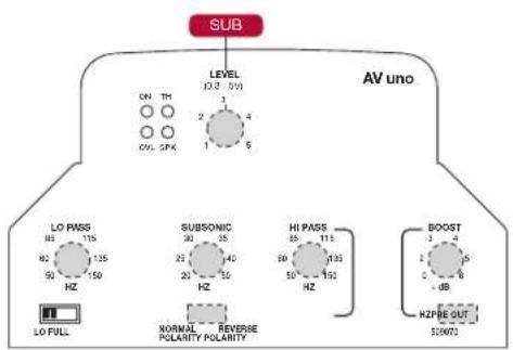
- LEVELS (0.3V - 5V): LEVELS (0.3V - 5V): Input sensitivity of the Left and Right channel control. Set the knob on position 1. Use a CD as a source and increase the source volume until you hear distortion, then lower it slightly to eliminate distortion. Increase the amplifier LEVELS to optimize the output signal without distortion.
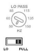
- PASS MODE (LO - FULL): Switch to select filter type. Select FULL to get a full range output signal. Select LO to get an output signal to drive a SUB / WOOFER. The output cut-off frequency should be set by adjusting the LO PASS knob (see section 3).
- LO PASS (50 Hz ÷ 150 Hz): Low-pass filter cut-off frequency adjustment. By turning the knob it is possible to vary the cut-off frequency from 50 Hz to 150 Hz @ 24dB/Oct.
- SUBSONIC (20 Hz ÷ 50Hz): Subsonic filter cut-off frequency adjustment. By turning the knob it is possible to vary the cut-off frequency from 20 Hz to 50 Hz with a 24dB/Oct slope. With this filter it is possible to eliminate the ultra-low frequencies which some audio signals carry and which might cause undesired distortions.
- NORMAL / REVERSE POLARITY: Phase signal adjustment. Select NORMAL POLARITY to not have phase rotations. Select REVERSE POLARITY to have 180irc phase rotation.
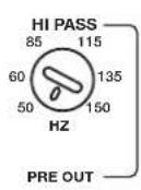
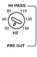
- HI PASS PRE OUT (50 Hz ÷ 150 Hz): PRE OUT output Hi-Pass filter cut-off frequency adjustment. By turning the knob it is possible to vary the cut-off frequency from 50 Hz to 150 Hz @ 12dB/Oct.
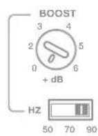
- BOOST (0 +6dB): Equalizer level adjustment. When set to 0 position, the equalizer is off. By increasing the adjustment level, the low frequency level increases according to the range selected by setting the BOOST Hz 50-70-90 switch (see section 8). With this function it is possible to improve the system's performance at low frequencies.
- BOOST FREQUENCY (50 Hz - 70 Hz - 90 Hz): Switch to select the equalizer adjustment frequency. Set the desired level by turning the BOOST knob (see section 7).
- POWER ON: The green LED indicates that the amplifier is on. If LEDs 9, 10, 11 and 12 are simultaneously lit, the amplifier will turn off and it will be necessary to contact technical support.
-
THERMAL: The red LED indicates the amplifier temperature. It flashes at 60irc C and the output power is limited by 1.5 dB. The flashing frequency increases around 70irc C where the output power is limited by 3 dB. The LED lights up without flashing at about 80irc C when the amplifier thermal protection starts operating. The amplifier will restart at about 70irc C.
-
OVERLOAD: The orange LED indicates an output overload. It flashes when the output load drops below the minimum permitted, allowing the amplifier to operate at a lower power. If the load drops below about 0.5 ohm impedance, the LED will turn on without flashing and activate the amplifier protection. If when listening to music the sound stops for a while, check if the orange LED flashes; it means there was an overload. Turn the amplifier off and check speakers and wiring.
- SPEAKER: The yellow LED indicates a fault in the speaker connection. It turns on when a speaker terminal short-circuits with the vehicle chassis. If when listening to music the sound stops for a while, check if the yellow LED flashes; it means there was a short-circuit between a speaker terminal and the vehicle chassis. Turn the amplifier off and check speakers and wiring.
8.2 AMPLIFIER SETTINGS
The AV uno amplifier features a versatile, completely independent filter section. Once you choose a power output configuration, you can adjust the PRE OUT output to your liking.
 |
■ Input Configuration
| INPUT | FILTER | PRE OUT | AMP |
| L & R | FULLLo-PASS @24 dB | L & RHi-PASS @12 dB | MIXL+R IN |
| L | FULLLo-PASS @24 dB | LHi-PASS @12 dB | LIN |
| R | FULLLo-PASS @24 dB | RHi-PASS @12 dB | R IN |
- FULL RANGE


AMP

line
| Frequency (Hz) | Value | | -------------- | ----- | | 20 | 0.8 | | 200 | 0.8 | | 2K | 0.8 | | 20K | 0.8 |PREOUT
line
| Frequency | Value | | --------- | --------- | | 50 Hz | 150 Hz |- LO PASS


AMP

line
| Frequency (Hz) | Value | |---|---| | 50 Hz | 150 |PREOUT

line
| Frequency | Value | |---|---| | 50 Hz | 150 Hz |8.3 EXAMPLE: PRE INPUT / PREOUT / DOUBLE SUBWOOFER

8.4 EXAMPLE: DUAL MONO PRE INPUT / PREOUT

8.5 EXAMPLE: SPEAKER INPUT / PREOUT DOUBLE SUBWOOFER


9. ACCESSORIES: AV BIT IN
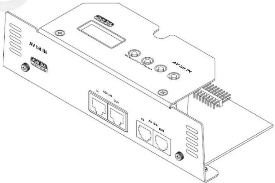
Digital interface for all AV amplifiers. It allows a seamless digital connection with bit One and bit Ten D processors via the AD Link/AC Link connection.
By inserting the AV bit IN "Digital Interface" into AV amplifiers, the digital signal in S/PDIF format, through the AD Link connection, leads directly to the high-quality internal D/A converters. After that, the signal becomes analog and is immediately amplified protecting it from deterioration over long distances. The result is high-quality music not reachable with any other analog system.
AV bit IN ASC is the management interface, programmed to control all amplifier functions. The user can interact with the microprocessor which, without interfering with the sound, will adjust all possible settings. This section is dedicated to all those who want to exploit the unique features of this product.
Some functions are automatic and transparent to the user, while others require intervention during installation and calibration or modification. Accessing ASC you will find a series of menus that will list all the specific entries on which you can intervene.
9.1 HOW TO INSERT AV BIT IN
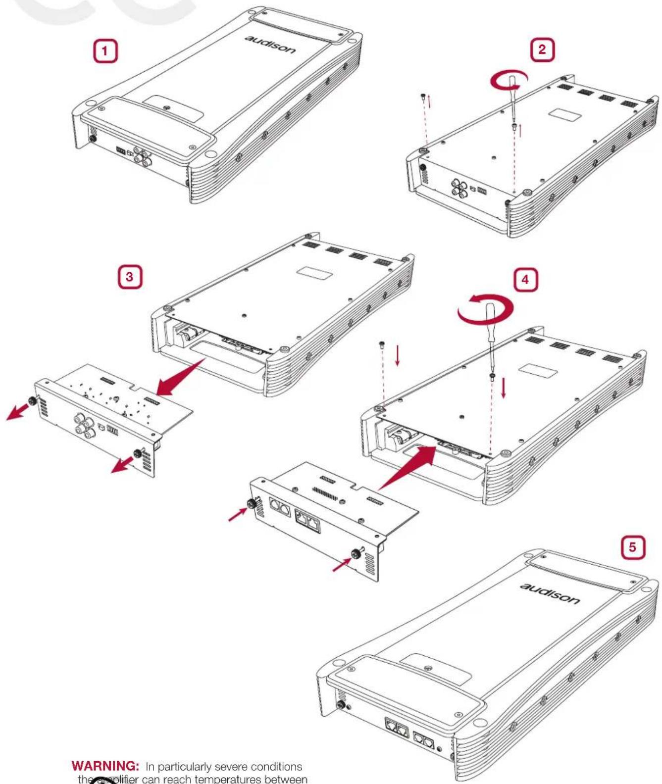
WARNING: In particularly severe conditions the amplifier can reach temperatures between 80 and 90°C (176 ÷ 194°F). Make sure the temperature is not dangerous before touching it.
9.2 FRONT PANEL
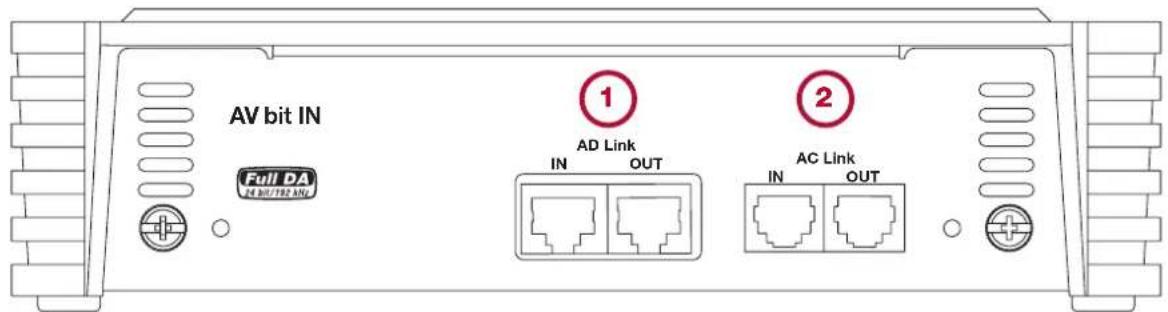
- AD Link: Digital audio bus that can transmit the signal of 8 channels. It exploits a Class 5 or 6 shielded cable for Ethernet networks normally used in computer networks.
AD Link IN: RJ-45 input terminal to connect a digital signal coming from other AV amplifiers or other external devices equipped with AD Link (bit One / bit Ten D).
AD Link OUT: RJ-45 terminal output for connection to external devices capable of receiving the AD Link digital signal (AV / TH amplifiers).
- AC Link: It is composed of a digital bus and control signals for the management of the functions of the device to which it is connected. It provides the ability to build a digital network interacting with other devices provided with AC Link such as AV / TH amplifiers and digital audio processors. The RJ-12 terminated cable is a 6-pin cable, like the one normally used for digital telephone purposes, but it is not compatible with digital telephone technology.
AC Link IN: RJ-12 input terminal for connection to the processor or other devices located upstream of the system (see 9.4).
AC Link OUT: RJ-12 input terminal for connection to the processor or other devices located downstream of the system (see 9.4).
The AC Link connection is able to provide power to the external device.
AC Link-Remote IN: If an amplifier provided with AV bit IN is connected to bit Ten D processor, the amplifier can be turned on via the processor, without the use of the amplifier Remote-In.
If another processor is used (bit One) or if there is a Thesis TH amplifier in the AC Link chain, the Remote-In function on the AC Link won't be available.
If in the AC Link chain there is an amplifier different from the AVs (Thesis TH), the Remote-In function on the AC Link has to be disabled. Set the AV bit IN AC Link Turn ON jumper to OFF as shown in the image below.


WARNING: for AC Link / AD Link connections, only use the cables supplied with the products. Important: adjust the amplifier volumes to position 1 (5V RMS) when using the AV bit IN module.
9.3 CONTROL PANEL DISPLAY
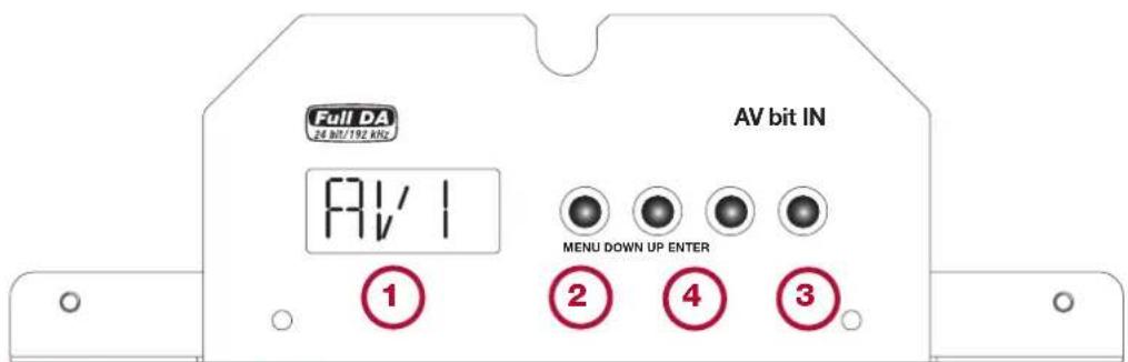
See 9.5: How to configure AV bit IN
- AV bit IN STATUS DISPLAY: This is the visual element of the AV bit IN system with a 3-character backlit LCD. While operating it can display all configuration parameters stored in the amplifier during the installation. The following pages contain all the messages and statements that may appear on the display from time to time.
- MENU: This button activates the AV bit IN and shows the first entry available. Each time you press this button while normally operating the amplifier, AV bit IN shows the first entry available and not the last entry on which you worked. At any point, if you press the MENU key you exit from AV bit IN management and automatically return to the home screen (default display) without saving your changes.
Note: At any point, if you do not touch the keys for 5 seconds, AV bit IN will automatically return to the home screen (default display) without saving your changes.
-
ENTER: This button is used to:
-
Confirm the selected entry,
- Save it,
-
Go to the next menu entry.
-
UP - DOWN: These buttons allow navigation through the available entries of various menus. Depending on the function, you can change the selection and then confirm by pressing the ENTER key.
9.4 HOW TO CONNECT THE AMPLIFIER EQUIPPED WITH AV BIT IN TO THE SYSTEM
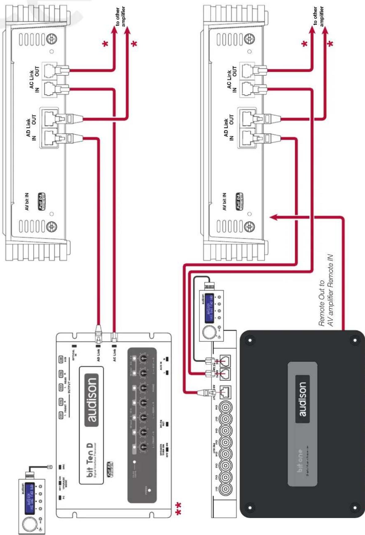
flowchart
graph TD
    subgraph "bit Ten D Signal Interface Processor"
        A["Full DA"] -->|AD Link IN OUT| B["AV bit IN"]
        C["AC Link IN OUT"] -->|to other amplifier| B
        D["AV bit IN"] -->|AD Link IN OUT| B
        E["Full DA"] -->|AD Link IN OUT| B
        F["Bit One"] -->|to other amplifier| B
    end

    subgraph "bit Ten D Audio System"
        G["Full DA"] --> H["AV bit IN"]
        I["AC Link IN OUT"] -->|to other amplifier| H
        J["AV bit IN"] --> K["AD Link IN OUT"]
        L["Full DA"] --> M["AD Link IN OUT"]
        N["Bit One"] --> O["Bit One"]
        P["Bit One"] --> Q["Bit One"]
    end

    style "bit Ten D" fill:#f9f,stroke:#333
    style "bit Ten D Audio System" fill:#ccf,stroke:#333
* Use AC Link / AD Link cables supplied with the products.
** Don't connect the remote input signal to the amplifiers when using AV bit IN module.
9.5 HOW TO CONFIGURE AV bit IN
Before starting the configuration of the amplifier or amplifiers equipped with an AV bit IN digital input module, set and finalize the processor (bit Ten D / bit One) that will interface with the system.
The processor channels specialized in "Digital output / AC Link - AD Link" will interface with the amplifiers equipped with the AV bit IN input module, as shown in the following procedure. In the "CHANNEL MAP" of the bit Ten D PC software, the specialized channel with digital output are highlighted in green, while for the bit One it should be written down which output channels are assigned the digital format (AD Link - AC Link) during the "I/O Configuration Wizard".

Set the processor overall volume at a level of -45 dB, which does not endanger the system speakers during installation / adjustment.
Before starting to configure the AV bit IN module and after setting the processor (bit Ten D / bit One), turn the sound system off and then on again using the DRC SRC knob.
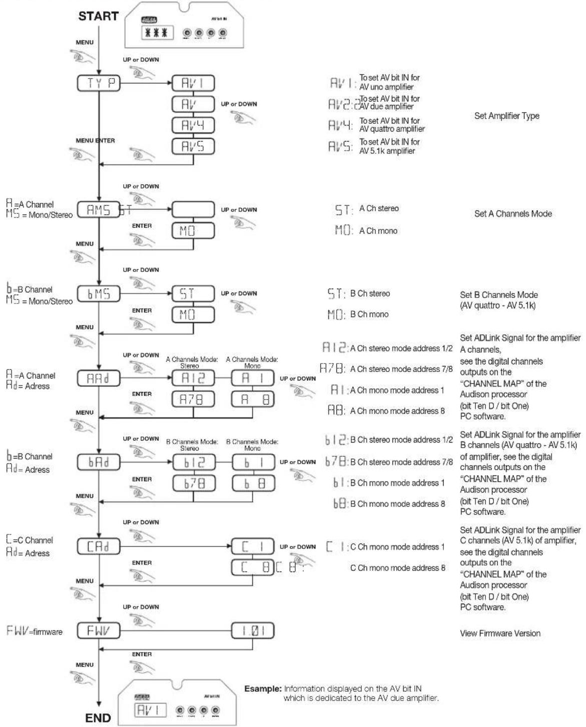
flowchart
graph TD
    A["START"] --> B["MENU"]
    B --> C["TYP"]
    C --> D["AV1"]
    D --> E["AV"]
    E --> F["AV4"]
    F --> G["AV5"]
    G --> H["UP or DOWN"]
    H --> I["AMS"]
    I --> J["ST"]
    J --> K["MO"]
    K --> L["UP or DOWN"]
    L --> M[" bMS "]
    M --> N["ST"]
    N --> O["MO"]
    O --> P["UP or DOWN"]
    P --> Q[" AAd "]
    Q --> R["APD"]
    R --> S["ENTER"]
    S --> T[" bAd "]
    T --> U[" ENTER "]
    U --> V[" b78 "]
    V --> W[" b12 "]
    W --> X[" b1 "]
    X --> Y[" UP or DOWN "]
    Y --> Z[" CAd "]
    Z --> AA[" ENTER "]
    AA --> AB[" C1 "]
    AB --> AC[" UP or DOWN "]
    AC --> AD[" FWV = firmware "]
    AD --> AE["IPW = firmware "]
    AE --> AF[" ENTER "]
    AF --> AG[" END "]

    subgraph Inputs
        AH["AV1: To set AV bit IN for AV uno amplifier"] --> AI["AV2: To set AV bit IN for AV due amplifier"]
        AJ["AV4: To set AV bit IN for AV quattro amplifier"] --> AK["AV5: To set AV bit IN for AV 5.1k amplifier"] --> AL["Set Amplifier Type"]
        AM["ST: A Ch stereo"] --> AN["MO: A Ch mono"] --> AO["Set A Channels Mode"]
        AP["ST: B Ch stereo"] --> AQ["MO: B Ch mono"] --> AR["Set B Channels Mode (AV quattro - AV 5.1k)"]
        AS["A12: A Ch stereo mode address 1/2"] --> AT["A78: A Ch stereo mode address 7/8"] --> AU["A1: A Ch mono mode address 1"]
        AV["A12: A Ch stereo mode address 7/8"] --> AW["A8: A Ch mono mode address 8"] --> AX["Set ADLink Signal for the amplifier A channels, see the digital channels outputs on the "CHANNEL MAP" of the Audison processor (bit Ten D / bit One) PC software."]
        AY["b12: B Ch stereo mode address 1/2"] --> AZ["b78: B Ch stereo mode address 7/8"] --> BA["b1: B Ch mono mode address 1"]
        BB["b78: B Ch stereo mode address 7/8"] --> BC["b8: B Ch mono mode address 8"] --> BD["b8: B Ch mono mode address 8"] --> BE["Set ADLink Signal for the amplifier B channels (AV quattro - AV 5.1k) of amplifier, see the digital channels outputs on the "CHANNEL MAP" of the Audison processor (bit Ten D / bit One) PC software."]
        BF["C1: C Ch mono mode address 1"] --> BG["C Ch mono mode address 8"] --> BH["Set ADLink Signal for the amplifier C channels (AV 5.1k) of amplifier, see the digital channels outputs on the "CHANNEL MAP" of the Audison processor (bit Ten D / bit One) PC software."]
        BI["View Firmware Version"] --> BJ["END"]
    end
9.6 EXAMPLE FULL DA: DOUBLE SUBWOOFER with Audison bit Ten D
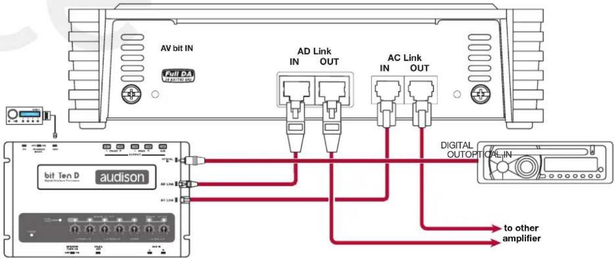


Subwoofer address 5
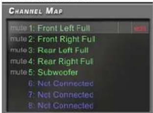
bit Ten D Configuration

9.7 EXAMPLE FULL DA: DUAL MONO with Audison bit Ten D

flowchart
graph TD
    A["MONO LEFT"] --> B["AV bit IN"]
    A --> C["AD Link IN OUT"]
    A --> D["AC Link IN OUT"]
    E["MONO RIGHT"] --> F["AV bit IN"]
    E --> G["AD Link IN OUT"]
    E --> H["AC Link IN OUT"]
    I["bit Ten D audison"] --> J["OPTICAL IN"]
    I --> K["DIGITAL OUT"]

9.8 EXAMPLE FULL DA: DOUBLE SUBWOOFER with Audison bit One


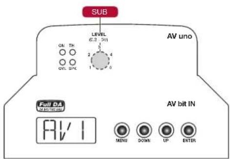


Subwoofer address 5

bit One Configuration

9.9 EXAMPLE FULL DA: DUAL MONO with Audison bit One

10. TECHNICAL SPECIFICATIONS
POWER SUPPLY
| Power supply voltage: | 11 ÷ 15 VDC |
| Idling current: | 2 A |
| Idling current when off: | 0.02 mA |
| Consumption @ 14.4 VDC (Max Musical Power): | 120 A |
AMPLIFIER STAGE
| Distortion - THD (1kHz @ 4Ω): | 0.04 % |
| Bandwidth (-3 dB): 7 ÷ 20k Hz | |
| S/N ratio (A weighted @ 1V): | 95 dBA |
| Damping factor (1k Hz @ 4Ω): | 160 |
| Input sensitivity: | 0.3 ÷ 5 V RMS |
| Input impedance: | 15k Ω |
| Speaker-In sensitivity: | 1.4 ÷ 24 V RMS |
| Speaker-In impedance: | 5k Ω |
| Minimum load impedance: | 1Ω |
| NOMINAL POWER (RMS) @ 12 VDC, THD 0.3%, 4Ω: | 700 W x 1 |
| OUTPUT POWER (RMS) @ 14.4 VDC,THD 1%: | |
| • 1 Ch: | 700 W x 1 (4Ω) |
| • 1 Ch: | 1300 W x 1 (2Ω) |
| • 1 Ch: | 1700 W x 1 (1Ω) |
CEA SPECIFICATIONS

Output power @ 4Ω, 1% THD+N, 14.4 V: 700 W x 1 Ch
SN ratio (ref. 1W output): 80 dBA
SIGNALS INPUTS / FILTERS
| Inputs: Pre IN / Speakers IN | |
| Outputs: | Hi-Pass |
| Filters (Full / Lo-Pass): 50 ÷ 150 Hz @ 24 dB/Oct. | |
| Speaker polarity: Normal / Inverted | |
| Bass Boost (Freq. / Gain): 50-70-90 Hz / 0 ÷ 6 dB | |
| Subsonic (Cont. adj.): Off ÷ 50 Hz @ 24 dB/Oct. | |
OTHER FUNCTIONS
| Remote IN: 7 ÷ 15 VDC - 1mA | |
| Remote OUT: 12 VDC - 50mA | |
| Fuse (strip type): 100 A | |
| Remote SUB volume adj. (with Lo-Pass 24 dB): | (-50 ÷ 6) dB |
SIZE / WEIGHT
| Max size (mm/inches): 220 x 470 x 58 / 8,66" x 18,50" x 2,28" | |
| Weight (kg/lb): | 7.2 / 15.87 |
www.audison.eu

- SAFE SOUND 05
- PRECAUTIONS 06
- INSTALLATION 07
- REAR PANEL 08
- FRONT PANEL 11
- INPUT CONTROLS 14
- ACCESSORIES: AV bit IN 21
- TECHNICAL SPECIFICATIONS ....31
- INTRODUCTION
- THE AV uno AMPLIFIER PROJECT
- PACKAGING CONTENT
- AVAILABLE ACCESSORIES (not provided)
- SAFE SOUND
- INSTALLATION
- FRONT PANEL
- INPUT CONTROLS
- INPUT CONTROLS
- CONTROL PANEL: SWITCHES AND ADJUSTMENTS
- AMPLIFIER SETTINGS
- ACCESSORIES: AV BIT IN
- HOW TO INSERT AV BIT IN
- FRONT PANEL
- CONTROL PANEL DISPLAY
- HOW TO CONFIGURE AV bit IN
- TECHNICAL SPECIFICATIONS
- CEA SPECIFICATIONS
Brand : AUDISON
Model : VOCE AV uno
Category : Receiver