
LRx 6.SR - Receiver AUDISON - Free user manual and instructions
Find the device manual for free LRx 6.SR AUDISON in PDF.


| Product Type | Car Power Amplifier |
| Brand | Audison |
| Model | LRx 6.SR |
| Channels | 6 (Front, Rear, Center, Sub) |
| Power Supply Voltage | 11 ÷ 15 VDC |
| Idling Current | 1.1 A |
| Consumption @ 13.8 VDC (Max Musical Power) | 34.5 A (A config.) / 51 A (B config.) / 60.5 A (C config.) |
| Distortion - THD (1kHz) | 0.009% |
| Bandwidth (-3dB) | 4 Hz ÷ 85 kHz |
| Signal-to-Noise Ratio (A weighted @ 1V) | 105 dB |
| Damping Factor (1 kHz, 4 Ohms) | 240 |
| Input Sensitivity | 0.2 ÷ 5 VRMS |
| Input Impedance | 15 kOhms |
| Load Impedance (Front/Rear/Center/Sub) | 4 - 2 Ohms |
| Nominal Output Power (RMS @ 12VDC, THD 0.3%) | 55W x 5 (4 Ohms) |
| Output Power (RMS @ 13.8 VDC, THD 1%) - Config. A | 55W x 5 (4 Ohms) + 150W x 1 (4 Ohms) |
| Output Power (RMS @ 13.8 VDC, THD 1%) - Config. B | 80W x 5 (2 Ohms) + 150W x 1 (4 Ohms) |
| Output Power (RMS @ 13.8 VDC, THD 1%) - Config. C | 80W x 5 (2 Ohms) + 220W x 1 (2 Ohms) |
| Filters | Front/Rear: 12dB/Oct. Hi-Pass (20-150 Hz); Center: 12dB/Oct. Hi-Pass (40-900 Hz); Sub: 24dB/Oct. Lo-Pass (40-150 Hz); Subsonic: Bypass/24dB/Oct. Hi-Pass (16-32 Hz, pre-set 20 Hz) |
| Protections | RGP (Resettable Ground Protection), short circuit, DC on outputs, thermal overload, internal fuse |
| Dimensions (L x H x D) | 176 x 56 x 445 mm |
| Weight | 3.9 kg |
| Fuse Rating | 60 A (strip fuse) |
| Optional Accessories | VCR01K/VCRAK/VCRDK (remote sub volume), CLK2 Cooling Kit |
Frequently Asked Questions - LRx 6.SR AUDISON
User questions about LRx 6.SR AUDISON
0 question about this device. Answer the ones you know or ask your own.
Ask a new question about this device
Download the instructions for your Receiver in PDF format for free! Find your manual LRx 6.SR - AUDISON and take your electronic device back in hand. On this page are published all the documents necessary for the use of your device. LRx 6.SR by AUDISON.
USER MANUAL LRx 6.SR AUDISON
Audison measurement standards
(Power measures taken according to audison standard, 1998 edition)
- 12VDC and 13.8VDC;
- 1 kHz or crossover cut-off frequency;
- 0.3% THD @ nominal power; 1% THD @ continuous power;
-Tolerance:+10%;-5%; - Continuous power given by RMS Voltage measured on resistive load;
- The nominal power of the amplifier is measured upon a battery voltage of 12 Volts with a 4 Ohm load and with all channels in function.
audison
OWNER'S MANUAL
CAR POWER AMPLIFIER
PRINTED IN ITALY - Code 10125790
LR ^SR X6
natural_image
3D technical illustration of an audio amplifier module with visible ports and wiring (no text or symbols)audison
is a division of elettromedia
62018 Potenza Picena (MC) Italy
Tel. 0733.870870 • Fax 0733.870880 • http://www.audison.com • e-mail: com@audison.com
INTRODUCTION
INTRODUCTION
Audison thanks you for preferring this product and compliments you on your choice since it was designed in order to insure outstanding musical and instrumental performances.
Before use instructions, please carefully read the safety norms you have to respect in order to avoid unpleasant inconveniences and to enjoy this product at best.
PRECAUTIONS
- Avoid to install the amplifier where temperature is below 0°C or above 55°C and in non ventilated places.
- The amplifier needs 12VDC power supply voltage with negative to ground. Be sure that your car electric system is compatible with the amplifier ordinary functioning.
- For safer driving, we recommend to adjust volume not to drown external traffic sounds.
WARNING!:
While installing the amplifier, make sure that the cable coming from the battery positive pole (+) doesn't touch the amplifier heat sink.
The heat sink is directly connected to the battery negative pole (-) through the screws which fix it to the vehicle chassis. Its contact with the positive pole cable would cause short circuit and, thus, possible fires and battery damages.
Please connect power supply cables to the amplifier terminal blocks (POWER + and -) before and to battery AFTER, to get maximum safety.
CAUTIONS
INPUTS: If the source output signal ground (PRE OUT) is not connected to the source chassis and the system sound is not powerful enough or is distorted, try to solve the problem by connecting the output signal cable braided shield (PRE OUT) to a point of the source chassis.
OUTPUTS: Don't connect -L and -R power outputs to each other or to ground (car chassis). In case you use an external crossover, make sure that channels grounds are not connected one to the other.
INSTALLATION
audison cable PRODUCTS FOR ELECTRIC CONNECTIONS

audison cable

RECOMMENDED POWER SUPPLY CABLES
Cable must be chosen according to its length and to the system total power.
| POWER SUPPLY TERMINAL BLOCKS | CABLES | BATTERY + AND GROUND | |||
| 4 Ohms | MAINCRIMP 8 | For7 A.W.G. | POWERFLOW 7(red and black) | PR 62.19 R&B | RB 6.45.1G f = 6 (.24)RB 8.45.1G f = 8 (.31) |
| 2 Ohms | MAINCRIMP 8 | For5 A.W.G. | MAINPOWER 5(red and black) | PR 80.24 R&B | RB 6.58.1G f = 6 (.24)RB 8.58.1G f = 8 (.34) |
RECOMMENDED SPEAKERS CABLES
| SPEAKERS TERMINAL BLOCKS | CABLE | ||
| MAINCRIMP 14 | 5x096/20 (2x16 A.W.G.) + 1x093/20 (2x14 A.W.G.) | ||
| MAINCRIMP 14 | 5x093/20 (2x14 A.W.G.) + 1x092/20 (2x12 A.W.G.) | ||
RECOMMENDED SIGNAL CABLES
BEST series PIN-RCA/PIN-RCA extensions are available in the following sizes

BS 50 cm 50 (19.68 inch) BS 100 cm 100 (39.37 inch) BS 150 cm 150 (59.05 inch) BS 200 cm 200 (78.74 inch)
BS 300 cm 300 (118.11 inch) BS 400 cm 400 (157.48 inch) BS 450 cm 450 (177.16 inch) BS 500 cm 500 (196.85 inch) BS 600 cm 600 (236.22 inch)
INSTALLATION
AMPLIFIER FIXING

Fix the amplifier through the self-tapping screws (4.2 x 16) given with it.
COLLEGAMENTI ELETTRICI

CAUTION
For the system safer protection, we recommend the use of a strip fuse on the cable that connects the battery positive pole to the amplifier POWER (+) terminal block. This fuse has to be installed about 10 cm far from the battery; Its value will have to be equal or slightly higher (+10% approx.) than consumption @13.8 VDC, according to the different configurations (see "Technical features"). It will have to be equal to the sum of the values of all fuses in case system consists of several amplifiers or in case amplifiers have several fuses.
LRx 6.SR FUSE: 60A
| POWER SUPPLY CABLE SIZELength: 4/5 m | ||||
| Load | 4 Ohms | 2 Ohms | ||
| Unit of measure | mm ^2 | A.W.G. | mm ^2 | A.W.G. |
| LRx 6.SR | 8.6 | 7 | 15.2 | 5 |
CONTENTS
Description p. 4
In-Out panel
Functions 5
Power supply panel
Functions 6
Fuse replacement 7
Controls panel
Functions and controls 8
Setting panel
Functions 10
Subsonic filter activation 10
Subsonic filter cut-off frequency modification 11
VCA-VCA1D modules insertion 11
Technical features
Size for fixing 12
LRx 6.SR 12
Accessories
VCR01K, VCRAK and VCRDK 13
CLK2 - LRx Cooling Kit 14
Configurations
Block diagram 15
Configuration table 16
Controls panel diagram and subsonic filter switch 16
Configuration example
Front+Rear+Center+Sub 16
Installation
Logo rotation 17
Amplifier fixing 18
Electric connections 18
audison cable products for electric connections 19
audison measurement standards 20
DESCRIPTION
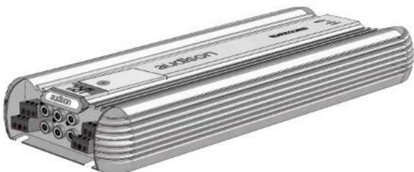
Audison LRx 6.5R:
Six channel car power amplifier characterised by excellent musical performances, small size and outstanding energy reserve.
Its PWM power supply stage is made with two pairs of 70A MOSFETs; it is stabilised and oversize. Input stage is provided with a special circuit (LNS) which allows the system disturbances rejection, reducing noise that is usually due to the vehicle electric parts (alternator, electronic injection, etc.), without altering musical signal quality.
Driver stage is characterised by a very linear circuitry; it has coupled differential transistors and an A Class complementary voltage amplifier. Power section has Darlington configuration with high gain and SOA (Safety Operation Area) BJT TO247. Thanks to its great capacity to supply current, this amplifier can easily drive even the hardest loads and satisfy whatever power needs. It can give 55W on Front, Rear and Center channels and 150W on sub with 4 Ohm load, 80W on Front, Rear and Center channels and 220W on sub at 2 Ohms in continuous mode. Differently from what occurs with other amplifiers, LRx 6.5R is not blocked by protection systems immediately below these load values. Its exclusive "Overload Limiter" circuit allows it to go on working, limiting output power and pointing out how hard the applied load is by the "Limit" LED blinking.
Its big power reserve, its constant control at low frequencies and its exquisite timbre qualities make it an ideal amplifier to realise systems designed to attain outstanding musical features and very high sound pressures (SPL).
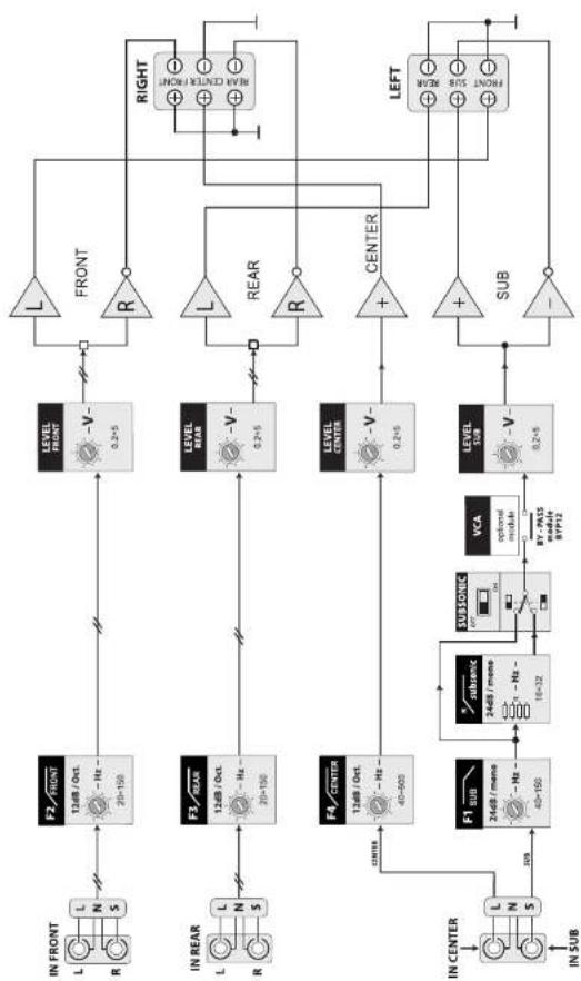
LRx 6.SR has a bypass subsonic filter (24dB/Oct.) with adjustable frequency, pre-set at 20Hz, and four Butterworth crossovers with Independent frequencies; three are HI-PASS (12dB/Oct.), the fourth is LO-PASS (24dB/Oct.).
In case LRx amplifiers are used in extremely difficult conditions (very low loads) or in installations where space is too narrow and their heat sink cooling is not enough, they can be employed together with CLK2 cooling system (optional). It is a system made of two units to apply onto the amplifier sides; each of them is provided with an electronically controlled fan that allows the amplifier thermal stabilisation (see "CLK2 – LRx Cooling Kit").
Protection includes:
- RGP (Resettable Ground Protection) circuit; in case a short circuit occurs between loudspeakers outputs and car chassis, it detects a high current flow in the pre-input ground and acts by putting the amplifier in stand-by, protecting its circuitry;
- a device against short circuits and against DC in the outputs, to protect loudspeakers;
- a device that detects the amplifier temperature excessive increase and stops its functioning until optimal conditions occur again.
Once the causes which implied protection circuits intervention have been checked and solved, the amplifier is reset by switching it off and on again.
The amplifier is also provided with another general protection which is insured by an internal strip fuse, very easy to reach.
Optional:
The following devices are available upon request:
1 - Three kits for subwoofer volume remote control:
• VCR01 and VCRAK (analogue and specific for subwoofer);
- VCRDK (digital; It can be used for master volume control or for level control of any ways in a multichannel system).
2 - CLK2 cooling system.
INSTALLATION
LOGO ROTATION

1 - Remove the transparent cover which protects controls and then the 4 screws which block the metal plate by using multispanner.
2 - Remove the plate without damaging the silkscreen printed panel which will have to stay on. We suggest that you seize both plate grips with your hands and pull them by blocking the silkscreen printed panel with your fingers against the amplifier chassis at the same time. This will permit to remove the plate from the panel without damages.

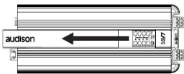
3 - Remove the strip with audison logo.
4 - Put the strip back again after turning it, so that audison logo is upside down.


5 - Mount the plate back by fixing it through the screws; then, re-assemble the transparent cover which protects controls.
CONFIGURATIONS
CONFIGURATION TABLE
LRx 6.SR can be configured as follows:
Front (Hi 12 dB) + Rear (Hi 12 dB) +
Center (HI 12 dB) + Sub (Lo 24 dB).
| SUB | FRONT | REAR | CENTER |
| F1 | F2 12-48/Oct. | F3 12-48/Oct. | F4 12-48/Oct. |
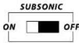
CONTROLS PANEL DIAGRAM AND SUBSONIC FILTER SWITCH

CONFIGURATION EXAMPLE
FRONT+REAR+CENTER+SUB

flowchart
graph TD
    A["Pre Out"] --> B["Rear"]
    B --> C["LRx 6.5R"]
    C --> D["Front L"]
    C --> E["Front R"]
    C --> F["Subweafer"]
    C --> G["Center"]
    C --> H["Midrange"]
    C --> I["Wheeler"]
    C --> J["Tweeler"]
    C --> K["CX"]
    C --> L["CX"]
    C --> M["CX"]
    C --> N["CX"]
    C --> O["CX"]
    C --> P["CX"]
    C --> Q["CX"]
    C --> R["CX"]
    C --> S["CX"]
    C --> T["CX"]
    style A fill:#f9f,stroke:#333
    style B fill:#ccf,stroke:#333
    style C fill:#cfc,stroke:#333
    style D fill:#fcc,stroke:#333
    style E fill:#cff,stroke:#333
    style F fill:#ffc,stroke:#333
    style G fill:#cfc,stroke:#333
    style H fill:#fcc,stroke:#333
    style I fill:#ffc,stroke:#333
    style J fill:#cfc,stroke:#333
    style K fill:#fcc,stroke:#333
    style L fill:#ffc,stroke:#333
    style M fill:#cfc,stroke:#333
    style N fill:#fcc,stroke:#333
    style O fill:#ffc,stroke:#333
    style P fill:#cfc,stroke:#333
    style Q fill:#fcc,stroke:#333
    style R fill:#ffc,stroke:#333
    style S fill:#cfc,stroke:#333
16
IN-OUT PANEL
FUNCTIONS

FRONT/REAR/CENTER/SUB
Power outputs of the amplifier Front, Rear, Center and Sub channels. Connect the speakers cables to these outputs according to polarity. Terminal blocks accept cables up to 9 A.W.G. max (see "audison cable products for electric connections" as far as their size is concerned). We recommend the use of audison cable products.

natural_image
Diagram of a cylindrical electronic component with internal structure and an arrow indicating direction (no text or symbols)
PPS (Phantom Power Supply) Power supply socket for audison external audio accessories.


IN FRONT
Left (L) and right (R) channels inputs of the amplifier Front system. Front preamplified outputs of a source (head unit, CD player, DAT, etc.) or of an external electronic crossover must be connected to them.

IN REAR
Left (L) and right (R) channels inputs of the amplifier REAR system. Rear preamplified outputs of a source (head unit, CD player, DAT, etc.) or of an external electronic crossover must be connected to them.

IN CENTER
Mono input for central channel. Center preamplified output of a surround processor (AC3, DTS, Dolby Pro Logic) must be connected to it.

IN SUB
Mono input for sub. The source Sub preamplified output must be connected to it.
5
POWER SUPPLY PANEL
FUNCTIONS

REMOTE IN
Terminal to connect Remote cable, which comes from the source and which controls the amplifier switching on. Applied voltage must be between 7 and 15VDC.


REMOTE OUT
Terminal to repeat the switching on control (Remote IN) coming from the source. It is used to switch on another amplifier or device in the system simultaneously. Available voltage is the same as the one applied on Remote IN.

VCR (optional kit)
Terminals to connect VCR01/VCRA/VCRD adjuster included in sub output volume remote control kits (VCR01K/VCRAK/VCRDK).

FUSE (60A)
Strip fuse. It insures the amplifier general protection. In case the fuse breaks down, please replace it by respecting its original value.
CAUTION: If you want to protect the system even more, please put a strip fuse onto the cable which connects the battery positive pole to the amplifier POWER (+) terminal block (see "Electric connections").

POWER
Terminal blocks for the amplifier power supply cable connection. Connect positive and negative poles according to indicated polarities. Holes have 8mm diameter and accept cables up to 3 A.W.G. max. In order to get the best current transfer, please use power supply cables with as big a section as possible. audison cable catalogue offers you a complete range of such products which can satisfy whatever demands; you can also find Maincrimp terminals in it. We strongly recommend their use because they contain the cable non protected end and allow the terminal block to fasten all its useful section.
CONFIGURATIONS
BLOCK DIAGRAM
flowchart
graph TD
    A["IN FRONT"] --> B["L 12dB / Oct. - Hz 20-150"]
    C["IN REAR"] --> D["L 12dB / Oct. - Hz 20-100"]
    E["IN CENTER"] --> F["L 24dB / mmH 40-100"]
    G["IN SUB"] --> H["L N S"]
    B --> I["LEVEL FRONT"]
    D --> J["LEVEL FRONT"]
    F --> K["LEVEL FRONT"]
    H --> L["LEVEL FRONT"]
    I --> M["V- 0.2+5"]
    J --> N["V- 0.2+5"]
    K --> O["V- 0.2+5"]
    L --> P["V- 0.2+5"]
    M --> Q["SUB"]
    N --> Q
    O --> Q
    P --> Q
    Q --> R["LEFT"]
    R --> S["NVBE + SITS + ONDR"]
    S --> T["RIGHT"]
    T --> U["INOR RELENT 40VBR"]
    U --> V["REF: 24dB / mmH 40-100"]
    V --> W["OFF: 10-32"]
    W --> X["SUB: 24dB / mmH 40-100"]
    X --> Y["OFF: 87/12"]
ACCESSORIES
CLK2 - LRx Cooling Kit
This cooling system is specially designed to provide LRx amplifiers with the right working temperature.
CLK2 should be used when LRx amplifiers work in extremely hard conditions (very low loads) or in installations where space is too narrow and heat sink cooling is not enough. It consists of two units to apply onto the amplifier sides; each of them is provided with an electronically controlled fan. Its intervention depends on a thermal sensor that starts the system as soon as LRx heat sink reaches 45°C. The same sensor is connected to a special circuit which controls the two fans speed progressive increase when temperature increases, too.
Air flux constant control allows the amplifier very good thermal stabilization and limits noise.

flowchart
graph TD
    A["First fan"] -->|→| B["audison"]
    C["Second fan"] -->|←| B
    B --> D["Battery 12 V"]
    B --> E["Ground"]
    B --> F["Power"]
    B --> G["Remote IN"]
    B --> H["Remote OUT"]
    B --> I["Remote"]
    style A fill:#f9f,stroke:#333
    style C fill:#f9f,stroke:#333
    style B fill:#ccf,stroke:#333
    style D fill:#cff,stroke:#333
    style E fill:#cff,stroke:#333
    style F fill:#ffc,stroke:#333
    style G fill:#ffc,stroke:#333
    style H fill:#ffc,stroke:#333
    style I fill:#ffc,stroke:#333
14
POWER SUPPLY PANEL
FUSE REPLACEMENT
natural_image
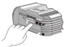
Illustration of a hand inserting into a stack of documents (no text or symbols visible)1 - Open the transparent cover by pushing the two teeth in its lowest corners to the direction indicated by the arrows.
2 - Remove the screws which fasten the fuse to eliminate pieces of the broken one; prevent them from going into the device.

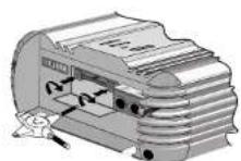
3 - Check the value of the new fuse to assemble, then fix it by gradually and alternately fastening the two screws. This will avoid voltage drops along the line and will make the device perfect functioning easier.
4 - Close the transparent cover.

natural_image
Illustration of a hand inserting a card into a stack of documents (no text or symbols visible)7
CONTROLS PANEL
FUNCTIONS AND CONTROLS

LIMIT (orange LED)
It indicates the Overload Limiter circuit is on.
Caution:
When this led is on (although sporadically), it means the applied load is a hard one. The activation of Overload Limiter circuit (output power limiter) will anyway allow the amplifier to function without distortions. In case Overload Limiter gets on too frequently (at every power peak), you will need to check if there are any failures or a too hard load (that's to say impedance is about 50% lower than the minimum recommended one). The amplifier can go on functioning in these conditions but power will inevitably decrease.

CENTER (Level)
It adjusts the amplifier Center channel Input sensitivity and sets its output level.
8
ACCESSORIES
VCR01K,VCRAK and VCRDK
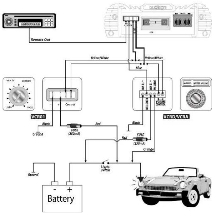
LRx 6.SR can accept one of the optional kits that allow the subwoofer volume remote control. VCR01K and VCRAK are analogue and special for sub; VCRDK is digital and can be used for master volume control or for level control of any ways in a multichannel system.
These kits are available as accessories and consist of three elements:
1) Volume adjuster (VCR01/VCRA/VCRD);
2) VCA/VCA1D module to put inside the amplifiers;
3) Wire to connect VCR01/VCRA/VCRD adjusters to the proper sockets in the amplifier rear panel and to the car lights switch, in order to light it up.
Install VCR01/VCRA/VCRD adjusters in a place you can easily and comfortably reach, according to the following connection diagram.
flowchart
graph TD
    A["Remote Out"] --> B["VCR01"]
    B --> C["Ground"]
    B --> D["Control"]
    D --> E["FUSE (250mA)"]
    E --> F["Red"]
    E --> G["Blue"]
    G --> H["VCRD/VCRA"]
    H --> I["Orange"]
    I --> J["Lights switch"]
    J --> K["Battery"]
    L["vCr Rx 0 min max"] --> M["+"]
    N["suction"] --> O["+"]
    P["yellow/White"] --> Q["Blue"]
    R["VOLTAGE CONTROL"] --> S["Black"]
    T["VOUTLE OUT"] --> U["Blue"]
    V["Ground"] --> W["-"]
    X["Ground"] --> Y["+"]
    Z["Ground"] --> AA["-"]
13
TECHNICAL FEATURES
SIZE FOR FIXING

* Drilling dimensions for fixing
LRx 6.SR
| POWER SUPPLYVoltage: ...... 11 ÷ 15 VDCIdling current:...... 1.1 AIdling current when off:...... 0.02 mAConsumption @ 13.8 VDC(Max Musical Power):- A config.(see Output Power):...... 34.5 A-B config.(see Output Power):...... 51 A-C config.(see Output Power):...... 60.5 AAMPLIFIER STAGEDistortion - THD (1kHz):...... 0.009 %Bandwidth (-3dB):...... 4 Hz ÷ 85 kHzS/N ratio(A weighed @ 1V):...... 105 dBDamping factor (1 kHz, 4 Ohms):...... 240Input sensitivity:...... 0.2 ÷ 5 VRMSInput impedance:...... 15 kOhmsLoad impedance:- Front/Rear/Center/Sub:...... 4 - 2 OhmsNominal output power (RMS)NP @ 12VDC; THD 0.3%:...... 55W x 5...... (4 Ohms) | Output power (RMS) @ 13.8 VDC;THD 1%- A config.: 55W x 5 (4 Ohms) + 150W x 1 (4 Ohms)- B config.: 80W x 5 (2 Ohms) + 150W x 1 (4 Ohms)- C config.: .... 80W x 5 (2 Ohms) + 220W x 1 (2 Ohms) |
| FILTERS/INPUTSFront - Rear: 12dB/Oct. Hi-Pass (20 ÷ 150 Hz)Center: 12dB/Oct. Hi-Pass (40 ÷ 900 Hz)Sub: 24dB/Oct. Lo-Pass(40 ÷ 150 Hz)Subsonlc: Bypass/ 24dB/Oct. Hi-Pass, 16÷32 Hz(pre-set at 20 Hz)Inputs: ... IN Front - IN Rear - IN Center - IN Sub | |
| OTHER FUNCTIONSRemote IN: ...... 7 ÷ 15 VDC - 1 mARemote OUT (3 Outs):...... 12 VDC - 10 mAAuxiliary power supply (PPS): ±12 VDC - 300 mAIN VCR (SUB volume) VCA/VCA1D attenuation: 100 dBFuse:...... 60 A | |
| MAX SIZE (L x H x D): ...... 176 x 56 x 445 mmWEIGHT:...... 3.9 kg |
CONTROLS PANEL

SUB (Level)
It adjusts the amplifier Sub channel input sensitivity and sets its output level.

F3
It permits to adjust the Rear channels 12dB/Oct. HI-PASS filter cut-off frequency between 40 Hz and 150 Hz.

REAR (Level)
It adjusts the amplifier Rear channels input sensitivity and sets its output level.

F4
It permits to adjust the Center channel 12dB/Oct. HI-PASS filter cut-off frequency between 40 Hz and 900 Hz.

FRONT (Level)
It adjusts the amplifier Front channels input sensitivity and sets its output level.

F2
It permits to adjust the Front channels 12dB/Oct. HI-PASS filter cut-off frequency between 20 and 150 Hz.

F1
It permits to adjust the subwoofer 24dB/Oct. LO-PASS filter cut-off frequency between 40 Hz and 150 Hz.

SAFETY (red LED)
It indicates that the amplifier protection circuits are on. In order for the amplifier to work again, you need to switch the system off and then on after 10 seconds at least. We recommend to check all connections before switching the amplifier on again.
If LED stays on, please contact Audison authorised after sale centres.
SETTING PANEL
FUNCTIONS
It permits to reach the resistors to set subsonic filter cut-off frequency, the switch which activates subsonic filter (SUBSONIC) and to insert VCA modules for the subwoofer volume remote control.

1 - Remove the setting panel in the amplifier bottom in order to carry out operations.


2 - Once operations have been carried out, please close the setting panel.
SUBSONIC FILTER ACTIVATION
Subsonic filter is activated through SUBSONIC switch under the setting panel.
- SUBSONIC switch permits to eliminate subsonic frequencies; these sounds cannot be heard by human ears but cause useless and damaging stress to amplifier and speakers. When it is on ON, frequencies below the chosen cut-off one are eliminated. Subsonic filter cut-off frequency can be adjusted through 4 Hz steps; this occurs by replacing the special resistors located into a socket which can be reached through the setting panel in the amplifier bottom. The amplifier is given with 20 Hz cut-off frequency.

SETTING PANEL
SUBSONIC FILTER CUT-OFF FREQUENCY MODIFICATION
Subsonic filter is pre-adjusted at 20 Hz. In order to modify this value, please act according to what follows.
Procedure:


Replace FS1, FS2, FS3, FS4 resistors according to the values in the setting panel table.
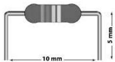
Remark: Cut the new resistors rheophores according to the size in the picture.
VCA-VCA1D MODULES INSERTION
LRx 6.5R can accept one of the three optional kits which allow the subwoofer volume remote control: VCR01K, VCRAK or VCRDK.
These kits have a specific module, VCA or VCA1D, to insert into the amplifier through the setting panel.
Installation:
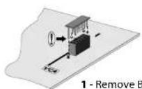
1 - Remove BYP12 bridge.
2 - Insert VCA/VCA1D module.


- Insertion key. It prevents the module from being inserted in the wrong way.

- Audison measurement standards
- OWNER'S MANUAL
- CAR POWER AMPLIFIER
- INTRODUCTION
- PRECAUTIONS
- WARNING!:
- CAUTIONS
- INSTALLATION
- audison cable
- CAUTION
- CONTENTS
- In-Out panel
- Power supply panel
- Controls panel
- Setting panel
- Technical features
- Accessories
- Configurations
- Configuration example
- DESCRIPTION
- Audison LRx 6.5R:
- Protection includes:
- Optional:
- CONFIGURATION TABLE
- CONTROLS PANEL DIAGRAM AND SUBSONIC FILTER SWITCH
- FRONT+REAR+CENTER+SUB
- FUNCTIONS
- FRONT/REAR/CENTER/SUB
- IN FRONT
- IN REAR
- IN CENTER
- IN SUB
- REMOTE IN
- REMOTE OUT
- VCR (optional kit)
- FUSE (60A)
- POWER
- BLOCK DIAGRAM
- CLK2 - LRx Cooling Kit
- FUSE REPLACEMENT
- FUNCTIONS AND CONTROLS
- LIMIT (orange LED)
- Caution:
- CENTER (Level)
- VCR01K,VCRAK and VCRDK
- SUB (Level)
- F3
- REAR (Level)
- F4
- FRONT (Level)
- F2
- F1
- SAFETY (red LED)
- SUBSONIC FILTER ACTIVATION
- SUBSONIC FILTER CUT-OFF FREQUENCY MODIFICATION
- VCA-VCA1D MODULES INSERTION
Brand : AUDISON
Model : LRx 6.SR
Category : Receiver