
LRx 3.1k - Receiver AUDISON - Free user manual and instructions
Find the device manual for free LRx 3.1k AUDISON in PDF.


| Product Type | Multi-channel car audio power amplifier |
| Model | LRx 3.1k |
| Number of Channels | 3 (2 full-range + 1 dedicated subwoofer) |
| Power Supply Voltage | 11 – 15 VDC |
| Internal Fuse | 100 A (AFS type) |
| Output Power (14.4 VDC, 4 Ω, 1% THD) | 170 W × 2 (A/B) + 750 W (SUB) |
| Output Power (14.4 VDC, 2 Ω, SUB) | 1150 W |
| Distortion (THD) A/B Channels | 0.08% @ 1 kHz, 4 Ω |
| Distortion (THD) SUB Channel | 0.5% @ 100 Hz, 4 Ω |
| Signal-to-Noise Ratio A/B | 103 dBA (ref. 1 V) |
| Signal-to-Noise Ratio SUB | 87 dBA (ref. 1 V) |
| Frequency Response A/B | 4 Hz – 62 kHz (-3 dB) |
| Frequency Response SUB | 7 Hz – 800 Hz (-3 dB) |
| Input Sensitivity (PRE IN) | 0.3 – 5 V |
| Input Sensitivity (Speaker IN) | 1.4 – 24 V |
| Filter Types | Hi-pass, Lo-pass, Bandpass, Subsonic, Boost 50 Hz |
| Filter Slope | 12 dB/Oct (A/B), 24 dB/Oct (SUB) |
| Subsonic Filter | OFF / 20 Hz / 30 Hz @ 24 dB/Oct |
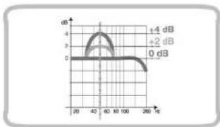
| Boost 50 Hz | OFF / +2 dB / +4 dB |
| Dimensions (W × L × H) | 7 13/16 × 19 1/4 × 2 1/4 in (198 × 538 × 56 mm) |
| Weight | 11.02 lb (5.0 kg) |
| Key Features | ECI interchangeable input modules, HCI hidden cable installation, SAF cooling, AMP microprocessor control, MSC modular construction, ART auto turn-on, ESV external sub volume |
Frequently Asked Questions - LRx 3.1k AUDISON
User questions about LRx 3.1k AUDISON
0 question about this device. Answer the ones you know or ask your own.
Ask a new question about this device
Download the instructions for your Receiver in PDF format for free! Find your manual LRx 3.1k - AUDISON and take your electronic device back in hand. On this page are published all the documents necessary for the use of your device. LRx 3.1k by AUDISON.
USER MANUAL LRx 3.1k AUDISON
LRx
The Universal Sound
audison
Manuale d'uso
LRx 3.1k
LRx 5.1k
Introduzione
10
11
LRx
The Universal Sound
audison
Manuale d'uso
LRx 3.1k
LRx 5.1k
natural_image
Pure technical line drawing of a mechanical component without any text, numbers, or symbolsnatural_image
Technical line drawing of a mechanical assembly with clamping tool (no text or symbols)Servizi

line
| Frequency (Hz) | Value | |---|---| | 20 | ~0.5 | | 50 | 50 | | 100 | 100 | | 2K | 100 | | 20K | 100 | | 30K | 100 | | 40K | 100 | | 50K | 100 | | 60K | 100 | | 70K | 100 | | 80K | 100 | | 90K | 100 | | 100K | 100 | | 110K | 100 | | 120K | 100 | | 130K | 100 | | 140K | 100 | | 150K | 100 | | 160K | 100 | | 170K | 100 | | 180K | 100 | | 190K | 100 | | 200K | 100 | | 210K | 100 | | 220K | 100 | | 230K | 100 | | 240K | 100 | | 250K | 100 | | 260K | 100 | | 270K | 100 | | 280K | 100 | | 290K | 100 | | 300K | 100 | | 310K | 100 | | 320K | 100 | | 330K | 100 | | 340K | 100 | | 350K | 100 | | 360K | 100 | | 370K | 100 | | 380K | 100 | | 390K | 100 | | 400K | 100 | | 410K | 100 | | 420K | 100 | | 430K | 100 | | 440K | 100 | | 450K | 100 | | 460K | 100 | | 470K | 100 | | 480K | 100 | | 490K | 100 | | 500K | 100 | | >55% (at threshold) | <5% (below threshold) for the range of frequencies from ~25 to ~5% (for higher frequencies). The chart includes a legend indicating '5B ≥15' and '≥5'.

line
| Time (s) | Value | | -------- | ----- | | 20 | 50±150 | | 200 | 50±150 |LRx
The Universal Sound
audison
Manuale d'uso
LRx 3.1k
LRx 5.1k
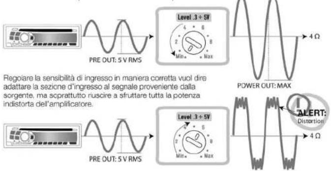
■ Level 0.3÷5 V (LRx 3.1k e LRx 5.1k)

Config. 7, 8, 9, 10, 11, 12

22
B Channels
Config. 1, 2, 7, 8


Config. 3, 4, 9, 10

line
12 dB/Oct. | X-axis (dB) | Y-axis Value | | :--- | :--- | | 20 | ~0.8 | | 200 | ~1.0 | | 2K | ~1.0 | | 20K | ~1.0 |Config. 5, 6, 11, 12


line
| Time (Hz) | Signal Value | |---|---| | 20 | 500K | | 2500 | 500K | | 3000 | 2500~5K | | 3500 | 2500~5K | | 4000 | 2500~5K | | 4500 | 2500~5K | | 5000 | 2500~5K | | 5500 | 2500~5K | | 6000 | 2500~5K | | 6500 | 2500~5K | | 7000 | 2500~5K | | 7500 | 2500~5K | | 8000 | 2500~5K | | 8500 | 2500~5K | | 9000 | 2500~5K | | 9500 | 2500~5K | | 10000 | 2500~5K |Config. 1, 3, 5, 7, 9, 11

SUB Channel
23
LRx
The Universal Sound
audison
Manuale d'uso
LRx 3.1k
LRx 5.1k
Config. 2, 4, 6, 8, 10, 12


line
| Time (Hz) | Value | | --------- | ----- | | 20 | 50 | | 210 | 150 |■ Subsonic SUB Channel (LRx 3.1k e LRx 5.1k)


line
| Frequency (Hz) | Value | | -------------- | ----- | | 20 | OFF |■ Boost 50 Hz SUB Channel (LRx 3.1k e LRx 5.1k)


line
| Frequency (Hz) | Amplitude (dB) | |---|---| | 0 | 0 | | 20 | 0 | | 40 | 3 | | 60 | 4 | | 80 | 3 | | 100 | 2 | | 120 | 1 | | 140 | 0 | | 160 | 0 | | 180 | 0 | | 200 | 0 | +2 dB +4 dBInstallazione
natural_image
Technical line drawing of a mechanical component with no visible text or symbolsnatural_image
Technical line drawing of a mechanical assembly with a 35-unit dimension标注 (no text or symbols present)natural_image
Technical illustration of a mechanical component with a screwdriver and warning symbol (no text or labels)natural_image
Technical illustration of a mechanical component with coiled cable and mounting holes (no text or symbols)


natural_image
Top-down cutaway view of a car showing internal components like seats, wheels, and dashboard (no text or labels)

The Transfer System
Bypass/Hi 50 ÷ 5k Hz
Bypass/Hi 50÷1k/Lo 250÷5kHz
Bypass/Lo 50 ÷ 150 Hz
OFF/20/30 Hz @ 24 dB/Oct.
OFF/+2 dB/+4 dB
+5÷-5dB
198×538×56
5.
37
LR×3.1k
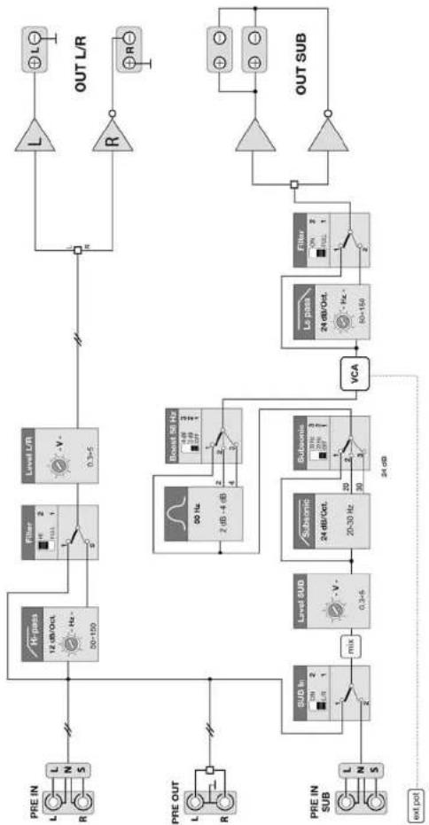
flowchart
graph TD
    A["PRE IN"] --> B["12 dB/Oct. 50-150"]
    C["R"] --> B
    B --> D["Filter 2 1"]
    D --> E["Level L/R 0.3-5"]
    E --> F["L"]
    G["PRE OUT"] --> H["2 dB -4 dB"]
    I["R"] --> H
    H --> J["Boost 56 Hz 0.8 dB 3/100 1"]
    K["PRE IN SUB"] --> L["SUB In 1 DM 2 L/R 1"]
    L --> M["mix"]
    M --> N["Level SUB 0.3-5"]
    N --> O["Subsonic 24 dB/Cct. 20-30 Hz"]
    O --> P["Subsonic 24 dB"]
    P --> Q["VCA"]
    Q --> R["Le pass 24 dB/Oct. 50-150"]
    S["OUT L/R"] --> T["L"]
    U["R"] --> V["OUT SUB"]
    W["OUT SUB"] --> X["OUT SUB"]
    Y["OUT SUB"] --> Z["OUT SUB"]
    style A fill:#f9f,stroke:#333
    style C fill:#f9f,stroke:#333
    style I fill:#f9f,stroke:#333
    style K fill:#f9f,stroke:#333
    style Q fill:#ccf,stroke:#333
    style R fill:#ccf,stroke:#333
    style S fill:#ccf,stroke:#333
    style T fill:#ccf,stroke:#333
    style U fill:#ccf,stroke:#333
    style V fill:#ccf,stroke:#333
NON-INDEPENDENT FREQUENCY CONTROL INDIPENDENT FREQUENCY CONTROL HI-PASS LO-PASS BANDPASS NON INVERTED AMPLIFIER INVERTED AMPLIFIER STEREO SIGNAL
LR5.1k

flowchart
graph TD
    subgraph PRE_IN
        L1["L"] --> N1["N"]
        R1["R"] --> S1["S"]
    end

    subgraph PRE_IN/OUT
        L2["L"] --> N2["L"]
        R2["R"] --> S2["S"]
    end

    subgraph PRE_IN_SUB
        L3["L"] --> N3["N"]
        S3["S"]
    end

    subgraph SUB
        L4["L"] --> N4["L+R"]
        S4["S"]
    end

    subgraph Level_A_Ch
        V1["0.3-5"] --> Hi-pass["12 dB/Oct., Hz - 50-250 x1 50-54 x19"]
        Hi-pass --> LoPass["12 dB/Oct., Hz - 250-5k"]
        LoPass --> Filter["2 W/NOS, 2 THI"]
        Filter --> L5["L"]
        R5["R"] --> OUT_A["⊕L"]
        OUT_A --> R6["⊕R"]
    end

    subgraph Level_B_Ch
        V2["0.3-5"] --> Hi-pass
        Hi-pass --> LoPass
        LoPass --> Filter
        Filter --> L7["L"]
        R7["R"] --> OUT_B["⊕L"]
        OUT_B --> R8["⊕R"]
    end

    subgraph Level_SUB
        V3["0.3-5"] --> Subsonic["24 dB/Oct., 20-30 Hz"]
        Subsonic --> Subsonic2["Subsonic 3/4/6/8/10/12/14/16/18/20/22/24/26/28/30/32/34/36/38/40/42/44/46/48/50/52/54/56/58/60/62/64/66/68/70/72/74/76/78/80/82/84/86/88/90/92/94/96/98/100<br>    end<br><br>    subgraph VCA<br>        V4[26-36"] --> Subsonic2
        Subsonic2 --> Subsonic2
        Subsonic2 --> 30Hz["30 Hz - 4 dB"]
        30Hz --> Boost50Hz["Boost 50 Hz - 4 dB / 3 dB / 2 dB / 1 dB / 1 dB / 1 dB / 1 dB / 1 dB / 1 dB / 1 dB / 1 dB / 1 dB / 1 dB / 1 dB / 1 dB / 1 dB / 1 dB / 1 dB / 1 dB / 1 dB / 1 dB / 1 dB / 1 dB / 1 dB / 1 dB / 1 dB / 1 dB / 1 dB / 30Hz<br>    end<br><br>    subgraph Subsonic<br>        V5[30Hz"] --> Subsonic2
        Subsonic2 --> Subsonic2
        Subsonic2 --> Boost50Hz
        Boost50Hz --> LoPass["Lo pass - 24 dB/Oct., Hz - 50-150"]
        LoPass --> Filter["Filter"]
        Filter --> L9["L"]
        L9 --> OUTSUB["⊕"]
    end

    subgraph Subsonic2
        V6["30Hz"] --> Subsonic2
        Subsonic2 --> Subsonic2
        Subsonic2 --> Boost50Hz
        Boost50Hz --> LoPass
        LoPass --> Filter
        Filter --> L10["L"]
        L10 --> OUTSUB
    end

    subgraph Subsonic
        V7["30Hz"] --> Subsonic2
        Subsonic2 --> Subsonic2
        Subsonic2 --> Boost50Hz
        Boost50Hz --> LoPass
        LoPass --> Filter
        Filter --> L11["L"]
        L11 --> OUTSUB
    end

    subgraph Subout
        V8["30Hz"] --> Subsonic2
        Subsonic2 --> Subsonic2
        Subsonic2 --> Boost50Hz
        Boost50Hz --> LoPass
        LoPass --> Filter
        Filter --> L12["L"]
        L12 --> OUTSUB
    end

    subgraph OUT_SUB
        V9["30Hz"] --> Subsonic2
        Subsonic2 --> Subsonic2
        Subsonic2 --> Boost50Hz
        Boost50Hz --> LoPass
        LoPass --> Filter
        Filter --> L13["L"]
        L13 --> OUTSUB
    end

    PRE_IN_REFLENDLEPRE_IN_OUTLEPRE_IN_SUBREFLENDLEREFLENDLEREFLENDLEREFLENDLEREFLENDLEREFLENDLEREFLENDLEREFLENDLEREFLENDLEREFLENDLEREFLENDLEREFLENDLEREFLENDLEREFLENDLEREFLENDLEREFLENDLEREFLENDLEREFLENDLEREFLENDLEREFLENDLEREFLENDLEREFLENDLEREFLENDLEREFLENDLEREFLENDLEREFLENDLEGEND
NON INDEPENDENT FREQUENCY CONTROL INDEPENDENT FREQUENCY CONTROL HI-PASS LO-PASS BANDPASS NON INVERTED AMPLIFIER INVERTED AMPLIFIER STEREO SIGNAL

CEA 2006 Specifications
CEA measurement standard
LRx 3.1k
Output power @ 4 Ohms, ≤ 1% THD+N, 14.4 Volts:
• 160 W x 2 Ch + 650 W x 1 Ch
S/N ratio (ref. 1 W output)
• 160 W Channels: 80 dBA
• 650 W Channel: 58 dBA
LRx 5.1k
Output power @ 4 Ohms, ≤ 1% THD+N, 14.4 Volts:
- 50 W × 2 Ch + 160 W × 2 Ch + 650 W × 1 Ch
S/N ratio (ref. 1 W output)
- 50 W Channels: 87 dBA
• 160 W Channels: 80 dBA
• 650 W Channel: 58 dBA
Audison measurement standard
Power measures taken according to Audison standard, 2005 edition
- 12 VDC and 14.4 VDC;
- 1 kHz or crossover cut-off frequency;
- 0.3% THD @ nominal power; 1% THD @ continuous power;
- Tolerance: +10%, -5%;
- Continuous power given by RMS Voltage measured on resistive load;
- The nominal power of the amplifier is measured upon a battery Voltage of 12 VDC with a 4 Ohm load and with all channels in function.
audison
PART OF ELETTROMEDIA - 62018 Potenza Picena (MC) Italy - T +39 0733 870 870 - F +39 0733 870 880 - www.elettromedia.it

audison
www.audison.eu

LRx
The Universal Sound
audison
Owner's manual
LRx 3.1k
LRx 5.1k
Introduction
Audison has always stood out for the innovations of its products.
Smart ideas, new solutions, unique circuitry functions created for satisfying enthusiasts and Audison designers' spirit of perfection.
LRx is a unique project; it derives from THESIS HV venti, a state-of-the-art amplifier, and follows its main principles, for the best acoustic performance.
LRx is revolutionary, innovative, since various functions are concentrated together in a single product for the first time.
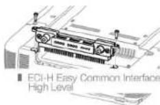
ECI - Easy Common Interface is an original, universal inputs system sporting interchangeable modules which can accept low and high level signals. ECI modules reversibility is combined with
HCI - Hidden Cables Installation
SAF - Smart Air Flow enhances thermal capacity; the heat sink size decreases, cooling increases and it is possible to get a compact, yet powerful amplifier.
LRx introduces AMP - Amplifier Management Processor, a microprocessor system which handles and controls the amplifier and which analyses the whole audio system.
MSC - Modular Soundproof Construction, the modular structure and the circuits layout were designed in order to get the ultimate sound quality.
A covered control panel shows the information it receives by the AMP about the working status; it has completely independent, bypass crossovers which can be configured in any ways.
The ART - Automatic Remote Turn On-Off function, the Easy Set Up; the ESV - External Subwoofer Volume and the supplied accessories complete the amplifier. These unique qualities are completed by digital amplification.
The advantages of great efficiency and low heat production have been achieved solving the problems of reliability, distortion and inability to drive difficult loads. Audison has developed a D class amplifier with a 220 kHz clock frequency, more than twice the current standards. This technique can reproduce the entire sound range, but is strengthened for Subwoofer frequencies. A performance-enhancing innovative solution with a terrific power impact for endless thrill.
LRx: it is enough to have a look at it, both inside and outside, to install it and listen to it to feel satisfied with owning something special.
The LRx 3.1k and 5.1k are multi-channel power amplifiers designed to drive complete systems. Two or four traditional high-power channels are combined to the performance and efficiency of digital technology to easily achieve bursting pressure levels. Front-Sub, Front-Rear-Sub or bi-amplified multi-way systems, ABDs still feature the same characteristics of Abs adding a final high-current digital section: 750 watt on 4 ohm and more than 1000 watt on 2 ohm. The versatile interface of the ECI modules and the independent filters with control capability, the practical service functions and the continuous electronic test of the operating status are the simplest way to add Audison sound to your system.
Table of contents
Introduction
Table of contents
Packing contents
Safe Sound
General precautions
ECI - Easy Common Interface Modules
LRx 3.1k ECI - L Low Level: Pre-amplified Input/Output module
LRx 3.1k ECI - H High Level: High Level Input/PRE Output module
LRx 5.1k ECI - L Low Level: Pre-amplified Input/Output module
LRx 5.1k ECI - H High Level: High Level Input/PRE Output module
ECI module installation
LRx 3.1k When mounting ECI in reverse
LRx 5.1k When mounting ECI in reverse
Power Supply/Outputs/Other Functions Panel
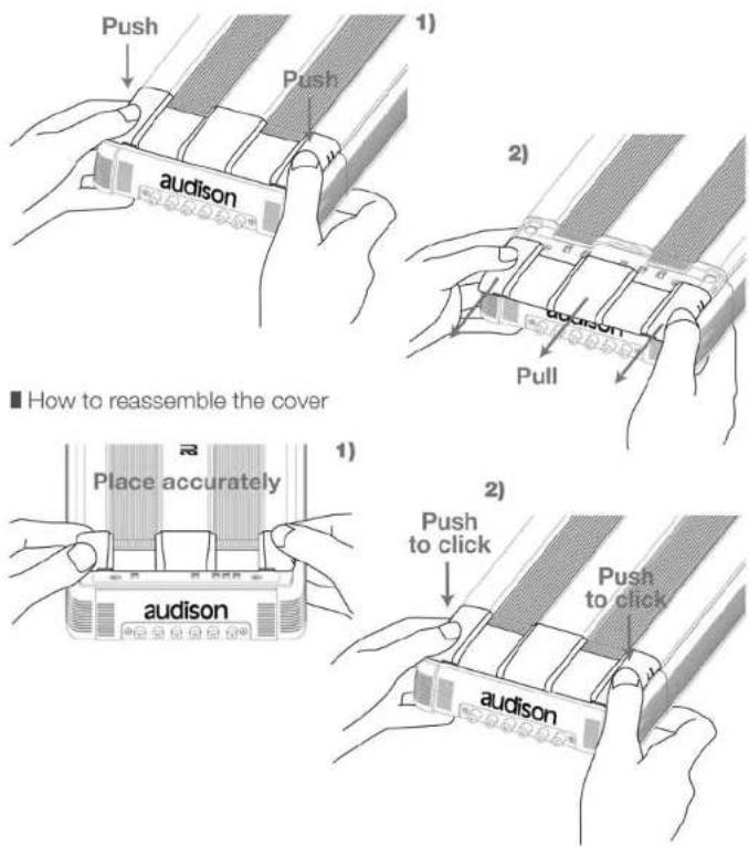
How to remove the cover
How to reassemble the cover
LRx 3.1k Power Supply and output terminal description
LRx 5.1k Power Supply and output terminal description
How to change the plate
Examples of how to use the plates
How to mount fast-on taker connectors
Other functions
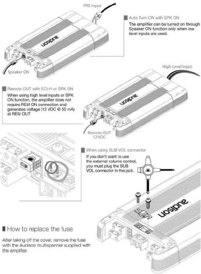
Auto Turn-ON with SPK ON
Remote OUT with ECI-H
When using SUB VOL connector
How to replace the fuse
Control Panel
How to remove the cover
How to reassemble the cover
LRx 3.1k functions
Out Mode
Configuration
Filter
Level 0.3÷5 V (LRx 3.1k and LRx 5.1k)
LRx 5.1k functions
Out Mode
Configuration
Filter
Subsonic SUB Channel (LRx 3.1k and LRx 5.1k)
Boost (LRx 3.1k and LRx 5.1k)
Installation
Amplifier fixing
Mounting template
How to run the cables under the amplifier
LEDS
Connection cables
Speaker Cable recommendations
Power and Ground Cable recommendations
Pattern
Audison logo in reverse
Patterns
Technical specifications
Block diagram
LRx
The Universal Sound
audison
Owner's manual
LRx 3.1k
LRx 5.1k
1 Packing contents
In the packing, besides your LRx 3.1k or LRx 5.1k, you will find:
• This Manual
• The warranty card
- Mounting template
- Semi-transparent protective cover for Control Panel
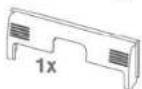
• Terminals covering plate with Audison logo
- Formed terminals covering plate for cables routing (preassembled)
- ECI-L Easy Common Interface – Low Level. Preamplified inputs/outputs module (preassembled)
- ECI-H Easy Common Interface - High Level. High level inputs/outputs module
• Audison Multispanner
• Cable guide clip
- Fast-on taker connectors
• SUB VOL connector (preassembled)
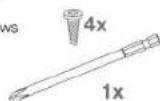
- 3.9x25 mm, self-tapping, cross-headed, fixing screws
• Extended length screw driver bit
- 100 A spare fuse.




SAFE SOUND
safe sound
AUDISON AMPLIFIERS USED IN HIGH POWER AUDIO SYSTEMS CAN GENERATE EXTREMELY HIGH UNDISTORTED SOUND PRESSURE. REMEMBER THAT CONTINUOUS EXPOSURE TO EXCESSIVE SOUND PRESSURE LEVELS MAY PERMANENTLY DAMAGE YOUR HEARING. USE COMMON SENSE AND PRACTICE SAFE SOUND.
Safety must be your first priority while driving. Listening levels should never exceed the noise coming from your vehicle or from outside it, in order for you to promptly react to emergency situations.
We recommend that you carefully follow the instructions in this manual to get the best performance from your new amplifier. Building a high quality car audio system demands good automotive and electronic knowledge to avoid potential problems; if you feel you do not have the correct tools or expertise, please visit a specialized installer. A state-of-the-art installation will ensure a thrilling performance without affecting your safety or your automobile reliability.
This manual was written for offering information about the amplifier installation and use. Despite the huge amount of data and recommendations, there might not be the exact mounting instructions you need for your car. If, after reading it, you still have questions regarding this product, go and see your AUDISON dealer.
In case you need more information, you can contact Audison after sales service by email at the following addresses:
- This symbol indicates that you have to pay attention to these instructions. Disregarding them might cause accidental harms or damage your amplifier.
- Before installing the amplifier, make sure you carefully read and understand all instructions.
- The vehicle electric system must have 12 VDC voltage with negative to ground. Make sure your car has it in order to avoid any damages to your amplifier and to the vehicle.
- Pre-plan the configuration of your new amplifier and the best wiring routes to ease installation.
• Always wear protective eyewear when using tools that may generate splinters. - During installation, keep the amplifier in its packing as long as possible; this will protect it from damages.
- Secure all auxiliary devices you built to install the components to the vehicle structure through brackets, screws, nuts and bolts; this insures stability and safety while driving.
- The amplifier detachment while driving can damage the people in the vehicle and other cars. Secure the amplifier at best, paying utmost attention if installation is inside the passenger's compartment. Use extra fixing systems if installation occurs inside the engine compartment.
- Before installing the amplifier, turn off the source and all other electronic devices in the audio system for preventing any damages.
- Make sure the location you chose for the components does not affect the correct functioning of the vehicle mechanic and electric devices.
- Do not run the cables or install the amplifier next to electronic gearcases.
- Use extreme caution when cutting or drilling the car plate, checking there are no electrical wiring or structural element underneath.
- Before connecting the power cable to the amplifier, disconnect the negative lead (-) from the car battery.
- Make sure power cable is not short circuited during installation and connection.
- Power cable must have mechanically resistant and self-extinguishing insulation.
Its section has to comply with what is suggested in this manual. Avoid to run it over or through sharp edges or close to moving mechanical devices. Make sure it is well fixed all along its length. Block positive and negative cables just close to the amplifier respective power supply terminal blocks through a clamping screw. - Use rubber grommets to protect the wire if it runs in a hole of the plate or proper materials if it is close to heat-generating parts.
- To ground the device (-) in the right way, use a screw in the vehicle chassis; scrape all point or grease from the metal if necessary, checking with a tester that there is continuity between the battery negative terminal (-) and the fixing point. If possible, connect all components to the same ground point; this solution rejects most noise.
- Route all signal cables close together and away from power cables.
- Never run cables outside the vehicle; you would not be protected against wear and in case of accidents.
- When installing speakers and the cables that connect them, make sure that non-insulated parts never touch the vehicle cutting parts. If they do, the amplifier protection is activated.

• To prevent all problems, use very good quality cables, connectors and accessories, choosing them in the CONNECTION Audison catalogue.
- When installation is over, and before plugging the main power supply fuse, check the system wiring and make sure all connections were done in the right way.
- Power amplifiers put an increased load on the battery and on its charging system. We recommend checking your alternator and battery condition to ensure they can handle the increased consumption. Standard electrical systems which are in good condition should be able to stand this extra load without problems but we recommend the use of an energy storage capacitor and/or a battery for high level audio systems.
- Put a fuse and its insulated fuse holder 40~cm max. far from the battery positive terminal; connect one end of the power cable to it after connecting the other end to the amplifier. The fuse value must be 50% higher than the amplifier built-in one. In case the cable supplies several amplifiers, the fuse value will have to be 50% higher than the sum of the values of all other fuses in the amplifiers.
- There must be good air circulation where the amplifier is installed; this area must not be affected by humidity, rain, external deposits or parts coming from the vehicle mechanical devices. Do not cover ducts for forced cooling.
• Install the amplifier in the vehicle parts where temperature is between 0°C (32°F) and 55°C (131°F).
WARNING. When working in demanding conditions, the amplifier can reach temperatures of around 80–90°C (176÷194°F). Make sure it is not dangerously hot before touching it.
- Periodically clean the amplifier without using aggressive solvents that might damage it. Dampen a piece of cloth with water and soap, wring it and clean the amplifier. Then use a piece of cloth dampened with water only; eventually clean the amplifier with a dry piece of cloth.
- Remove dust and solid deposits from the ducts where air goes in and out. Do not use compressed air on the grilles without removing them, since it would push solid parts in the amplifiers. If necessary, please contact a specialised service centre for internal cleaning. Air ducts obstruction makes the amplifier go in safety.
LRx
The Universal Sound
audison
Owner's manual
LRx 3.1k
LRx 5.1k
ECI - Easy Common Interface Modules
The LRx amplifier input section is totally new. Audison created ECI, an interchangeable interface module that is very easy to use. There are two different modules and you can choose what type of signal input to use to drive the amplifier. These modules are also reversible, enabling you to run the input cables underneath the amplifier through special recesses in the amplifiers bottom plate. Special cable guide clips are provided to fix the cables. This is very useful for tight installation spaces where you do not have the room to have cables protruding past the amplifier chassis. A label indicates the correct layout and function.
■ LRx 3.1k ECI - L Low Level: Pre-amplified Input/Output module
1_A Ch Input: Preamplified inputs for driving right and left A channels;
2_ BYPASS: Right and Left preamplified outputs. This output signal is not filtered. It outputs the A channel inputs signal;
3. SUB Ch Input: Right and Left preamplified inputs for driving the SUB channel, in the MIX function.

■ LRx 3.1k ECI - H High Level: High Level Input/PRE Output module
- Left PRE OUT: Left pre-amplified output. It outputs the A channel left input signal and is unfiltered;
2_A Ch Speaker Input: Amplified signals inputs for driving A channels Right and Left;
3_Out BYPASS (Speaker): Right and Left output. It outputs the A channels input signals; - SUB Ch Speaker Input: Right and Left amplified signals inputs for driving the SUB channel, in the MIX function;
- Right PRE OUT: Right pre-amplified output. It outputs the A channel right input signal and is unfiltered.

■ LRx 5.1k ECI - L Low Level: Pre-amplified Input/Output module
- A Ch Input: Preamplified inputs for driving right and left A channels;
2_B Ch Input/PRE OUT: Preamplified inputs for driving the Right and Left B channels; they can also be configured as Right and Left preamplified outputs. In this case, the output signal is not filtered; it outputs the A channel input signals; - SUB Ch Input: Right and Left preamplified inputs for driving the SUB channel, in the MIX function

■ LRx 5.1k ECI - H High Level: High Level Input/PRE Output module
- Left PRE OUT: Left preamplified output. This output signal is not filtered. It outputs the A channels left input signal;
2_A Ch Speaker Input: High level signal inputs for driving right and left A channels; - B Ch Speaker Input: High level signal inputs for driving right and left B channels;
- SUB Ch Speaker Input: Right and Left amplified signal inputs for driving the SUB channel, in the MIX function;
- Right PRE OUT: Right preamplified output. This output signal is not filtered. It outputs the A channels right input signal.

■ ECI module installation
1_ Remove the screws indicated in the drawing;
2. Remove the module by pulling it up, paying special attention not to bend the contacts which are perpendicular to the amplifier;
3_ Replace the module
with the one you want to use, or turn it with the contacts facing the amplifier inside, in the direction you choose;
4. Mount the module paying attention to the contacts:
5. Insert the module until it is all the way into its socket;
6. Fasten the screws making sure you do not force them.

LRx
The Universal Sound
audison
Owner's manual
LRx 3.1k
LRx 5.1k
■ LRx 3.1k When mounting ECI in reverse
A label is placed under the amplifier, near the input module, indicating the correct connections and configurations.
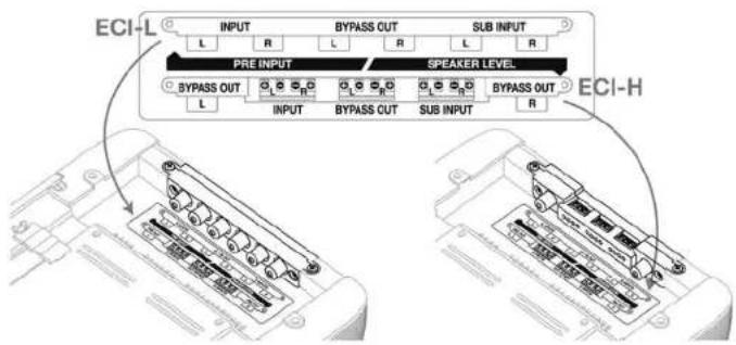
■ LRx 5.1k When mounting ECI in reverse
A label is placed under the amplifier, near the input module, indicating the correct connections and configurations.
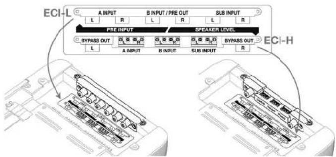
50
Power supply/Outputs/Other functions Panel
The panel with the power supply and speaker terminals is protected by a removable cover and end plate.
■ How to remove the cover
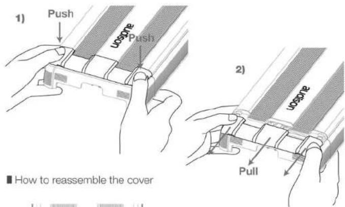

51
LRx
The Universal Sound
audison
Owner's manual
LRx 3.1k
LRx 5.1k
■ LRx 3.1k Power Supply and output terminal description
1_Protection fuse: 100 A;
2. Anti-short circuit protective shield;
3_-Power (Ground): terminal block for the amplifier power supply negative pole connection. Insert the battery negative cable or a wire connected to the vehicle chassis here.
The hole accepts cables up to 2 A.W.G. For the best current transfer, we recommend the use of cables with as big a section as possible or, at least, with the same section as the wire connected to the positive pole;
4 + Power (11÷15 VDC): terminal block for
the amplifier power supply positive pole connection. Insert the battery positive cable here. The hole accepts cables up to 2 A.W.G. For the best current transfer, we recommend the use of cables with as big a section as possible or, at least, with the same section as the wire connected to the negative pole;
5_ + Left A Speaker Out: + Left speaker power terminal of A channels;
6_ - Left A Speaker Out: - Left speaker power terminal of A channels;
7. + Right A Speaker Out: + Right speaker power terminal of
A channels;
8_ - Right A Speaker Out: - Right speaker power terminal of A channels;
9_Speaker SUB OUT: + and - speaker power terminal of the SUB output; the signal is MONO;
10_Speaker SUB OUT: + and - speaker power terminal of the SUB output; the outputs are connected in parallel to connect more than one speaker;
11_Remote Sub Volume: Inputs for sub volume remote control, optional VCRA;
12_Speaker ON: Inputs for turning on the amplifier through the speaker power cable. If source does not have a 12 VDC Remote output, connect any power output, even in parallel with a factory speaker, here for turning on the amplifier;
13. Remote IN/OUT: REM IN, terminal for the Remote cable coming from the device which turns on the amplifier. Voltage must be between 7 and 15 VDC. REM OUT, terminal for repeating Remote voltage and turning on other electronic devices. Output voltage is 12 VDC at 50 mA. Connection made to the SPK CN, also without the REM IN, will supply voltage to the REM OUT to turn on other devices.

■ LRx 5.1k Power Supply and output terminal description
1_Protection fuse: 100 A;
- Anti-short circuit protective shield;
3_-Power (Ground): terminal block for the amplifier power supply negative pole connection. Insert the battery negative cable or a wire connected to the
vehicle chassis here.
The hole accepts cables up to 2 A.W.G. For the best current transfer, we recommend the use of cables with as big a section as possible or, at least, with the same section as the wire connected to the positive pole;
4 + Power (11÷15 VDC): terminal block for
the amplifier power supply positive pole connection.
Insert the battery positive cable here. The hole accepts cables up to 2 A.W.G. For the best current transfer, we recommend the use of cables with as big a section as possible or, at least, with the same section as the wire connected to the negative pole;
5_ +/- Left A Speaker Out: + and - Left speaker power terminals of
A channels;
6_ +/- Right A Speaker Out: + and - Right speaker power terminals of A channels:
7 +/- Left B Speaker Out: + and - Left speaker power terminals of B channels:
8 +/- Right B Speaker Out: + and - speaker power terminals of B channels;
9. +/- Speaker SUB OUT: + and - speaker power terminals of the SUB output; the signal is MONO;
10. Remote Sub Volume: Inputs for sub volume remote control, optional VCRA;
11_ Speaker ON: Inputs for turning on the amplifier through the speaker power cable.
If source does not have a 12 VDC Remote output, connect any power output, even in parallel with a factory speaker, here for turning on the amplifier;
12. Remote IN/OUT: REM IN, terminal for the Remote cable coming from the device which turns on the amplifier. Voltage must be between 7 and 15 VDC. REM OUT, terminal for repeating Remote voltage and turning on other electronic devices. Output voltage is 12 VDC at 50mA . Connection made to the SPK ON, also without the REM IN, will supply voltage to the REM OUT to turn on other devices.
LRx
The Universal Sound
audison
Owner's manual
LRx 3.1k
LRx 5.1k
■ How to change the plate
Two plates are supplied with the amplifier. One is formed for exposed cable routing; the other, with the Audison logo, is closed for protecting and hiding the cables.
When you need to reassemble the plate,
match the tongue in pict. A and the location in pict. B.
match the tongue in pict. A and the location in pict. B.
match the tongue in pict. A and the location in pict. B.
match the tongue in pict. A and the location in pict. B.
match the tongue in pict. A and the location in pict. B.


■ Examples of how to use the plates
Power supply terminals are designed in order to allow mounting also with closed plate.
A special milling on the terminal enables the cable jacket to bend naturally.

If the amplifier is fixed to a panel, the given template tells you where to drill holes for running the cables.

natural_image
Pure technical line drawing of a mechanical component without any text, numbers, or symbols54
■ How to mount fast-on taker connectors
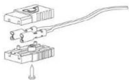
natural_image
Pure mechanical assembly diagram showing a lever mechanism with no text or symbols■ Other functions


flowchart
graph TD
    A["Power Input"] --> B["Amplifier"]
    B --> C["Speaker Output"]
    D["ON"] --> E["Ground"]
    F["AMP ON"] --> B
    G["Ground"] --> H["Ground"]
    I["Ground"] --> J["Ground"]
    K["Ground"] --> L["Ground"]
    M["Ground"] --> N["Ground"]
    O["Ground"] --> P["Ground"]
    Q["Ground"] --> R["Ground"]
    S["Ground"] --> T["Ground"]
    U["Ground"] --> V["Ground"]
    W["Ground"] --> X["Ground"]
    Y["Ground"] --> Z["Ground"]
    AA["Ground"] --> AB["Ground"]
    AC["Ground"] --> AD["Ground"]
    AE["Ground"] --> AF["Ground"]
    AG["Ground"] --> AH["Ground"]
    AI["Ground"] --> AJ["Ground"]
    AK["Ground"] --> AL["Ground"]
    AM["Ground"] --> AN["Ground"]
    AO["Ground"] --> AP["Ground"]
    AQ["Ground"] --> AR["Ground"]
    AS["Ground"] --> AT["Ground"]
    AU["Ground"] --> AV["Ground"]
    AW["Ground"] --> AX["Ground"]
    AY["Power Input"] --> AZ["Amp ON"]

flowchart
graph TD
    A["Speaker ON"] --> B["AMP OFF"]
    B --> C["Output"]
    D["OFF"] --> E["Ground"]
    F["3"] --> G["Amplifier"]
    H["5"] --> I["Amplifier"]
    J["7"] --> K["Amplifier"]
    L["9"] --> M["Amplifier"]
    N["12"] --> O["Amplifier"]
55
LRx
The Universal Sound
audison
Owner's manual
LRx 3.1k
LRx 5.1k
Control panel
The panel which contains the amplifier controls is protected by a removable cover.
■ How to remove the cover
LRx
The Universal Sound
audison
Owner's manual
LRx 3.1k
LRx 5.1k
■ LRx 3.1k functions

■ Out Mode
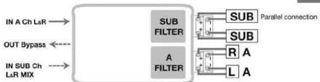
flowchart
graph LR
    A["IN A Ch L&R"] --> B["SUB FILTER"]
    C["OUT Bypass"] <--_D["SUB"]
    E["IN SUB Ch L&R MIX"] --> F["A FILTER"]
    B --> G["R A"]
    B --> H["L A"]
    G --> I["Parallel connection"]
    H --> I
Configuration
To set the control panel switches, please refer to the following pages.
■ Filters configuration

You can drive the whole amplifier with the Right and Left inputs of A channels; or, you can use the A inputs for A channels and the SUB inputs for the SUB channel.
■ Inputs configuration

When using the SUB INPUT with a stereophonic signal, a Mix L+R adder is applied to the SUB amplified output as the specific amplifier is monophonic. If the signal is monophonic, you can use either RCA connector named SUB Ch.
Filter
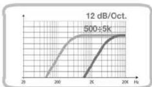
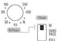
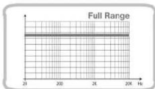
LRx amplifiers have a flexible, completely independent filter section.
After choosing the configuration you like, you can easily adjust every channel the way you prefer.
Config. 1, 2

Config. 3, 4

SUB Channel
Config. 1,3

Config. 2.4

A Channels
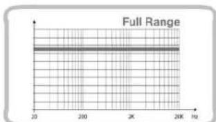
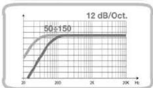
line
12 dB/Oct. | Frequency (Hz) | Value | | :--- | :--- | | 20 | ~0.1 | | 50 | 50±150 | | 2K | ~100 | | 2K | ~100 | | 2K | ~100 | | 2K | ~100 | | 2K | ~100 | | 2K | ~100 | | 2K | ~100 | | 2K | ~100 | | 2K | ~100 | | 2K | ~100 | | 2K | ~1, ~1, ~1, ~1, ~1, ~1, ~1, ~1, ~1, ~1, ~1, ~1, ~1, ~1, ~1, ~1, ~1, ~1, ~1, ~1, ~1, ~1, ~1, ~1, ~1, ~1, ~1, ~1, ~1, ~1, ~1, ~1, ~1, ~1,
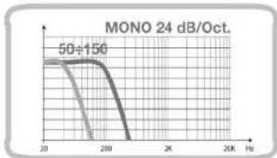
line
| X | Y | | ---- | ----- | | 20 | 50÷150 | | 200 | 50÷150 |LRx
The Universal Sound
audison
Owner's manual
LRx 3.1k
LRx 5.1k
■ Level 0.3÷5 V (LRx 3.1k and LRx 5.1k)
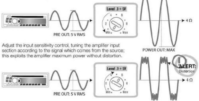

Adjust the input sensitivity control, tuning the amplifier input section according to the signal which comes from the source; this exploits the amplifier maximum power without distortion.
■ LRx 5.1k functions
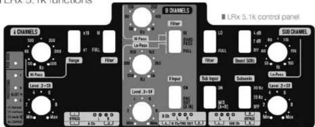
■ Out Mode

flowchart
graph LR
    IN_A["IN A Ch L&R"] --> SUB_FILTER1["SUB FILTER"]
    IN_B["IN B Ch L&R OUT Bypass"] --> SUB_FILTER2["SUB FILTER"]
    IN_SUBdiv["IN SUB Ch L&R MIX"] --> SUB_FILTER3["SUB FILTER"]
    SUB_FILTER1 --> R_R["R"]
    SUB_FILTER2 --> R_L["L"]
    SUB_FILTER3 --> R_R["L"]
    SUB_FILTER3 --> R_L["L"]
    A["A"] --> R_R["R"]
    A --> R_L["L"]
    A --> R_R["R"]
    A --> R_L["L"]
60
Configuration
To set the control panel switches, please refer to the following pages.
■ Filters configuration
| Config. | A Ch | B Ch | SUB |
| 1 | |||
| 2 | |||
| 3 | |||
| 4 | |||
| 5 | |||
| 6 | |||
| 7 | |||
| 8 | |||
| 9 | |||
| 10 | |||
| 11 | |||
| 12 |
You can drive the whole amplifier with the Right and Left inputs of A channels; otherwise, refer to the table below.
■ inputs configuration
| A CH | B CH | SUB CH | |
| IN INPUTSODI INPUTSODI INPUTSODI INPUTSODI INPUTSODI INPUTSODI INPUTSODI INPUTSODI INPUTSODI INPUTSODI INPUTSODI INPUTSODI INPUTSODI INPUTSODI INPUTSODI INPUTSODI INPUTSODI INPUTSODI INPUTSODI INPUTSODI INPUTSODI INPUTSODI INPUTSODI INPUTSODI INPUTSODI INPUTSODi I IN | AIN | AINB=PRE OUT | MIXA+B IN |
| IN INPUTSODI INPUTSODI INPUTSODI INPUTSODI INPUTSODI INPUTSODI INPUTSODI INPUTSODI INPUTSODI INPUTSODI INPUTSODI INPUTSODI INPUTSODI INPUTSODI INPUTSODI INPUTSODI INPUTSODI INPUTSODI INPUTSODI INPUTSODI INPUTSODI INPUTSODI INPUTSODI INPUTSODi I IN | A IN | BIN | MIXA+B IN |
| IN INPUTSODI INPUTSODI INPUTSODI INPUTSODI INPUTSODI INPUTSODI INPUTSODI INPUTSODI INPUTSODI INPUTSODI INPUTSODI INPUTSODI INPUTSODI INPUTSODI INPUTSODI INPUTSODI INPUTSODI INPUTSODI INPUTSODI INPUTSODI INPUTSODI INPUTSODI INPUT SODI INPUTSODI INPUTSODI INPUTSODI INPUTSODI INPUTSODI INPUTSODI INPUTSODI INPUTSODI INPUTSODI INPUTSODI INPUTSODI INPUTSODI INPUTSODI INPUTSODI INPUTSODI INPUTSODI INPUTSODI INPUTSODI INPUTSODI INPUTSODI INPUTSODI INPUTSODI INPUTSODI INPUTSODI INPUT SODI INPUTSODI INPUTSODi I IN | AIN | AINB=PRE OUT | SUB IN |
| IN INPUTSODI INPUTSODI INPUTSODI INPUTSODI INPUTSODI INPUTSODI INPUTSODI INPUTSODI INPUTSODI INPUTSODI INPUTSODI INPUTSODI INPUTSODI INPUTSODI INPUTSODI INPUTSODI INPUTSODI INPUTSODI INPUTSODI INPUTSODI INPUTSODI INPUTSODI INPUTSODI INPUTSOTD I IN | AIN | BIN | SUB IN |
When using the SUB INPUT with a stereophonic signal, a Mix A+B adder is applied to the SUB amplified output as the specific amplifier is monophonic. If the signal is monophonic, you can use either RCA connector named SUB Ch.
LRx
The Universal Sound
audison
Owner's manual
LRx 3.1k
LRx 5.1k
Filter
LRx amplifiers have a flexible, completely independent filter section.
After choosing the configuration you like, you can easily adjust every channel the way you prefer.
A Channels
■ Config. 1, 2, 3, 4, 5, 6

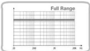
■ Config. 7, 8, 9, 10, 11, 12


line
| X-Axis | Y-Axis | |---|---| | 20 | ~1.5 | | 250 | ~3.0 | | 300 | ~4.5 | | 350 | ~5.0 | | 400 | ~5.5 | | 450 | ~6.0 | | 500 | ~6.5 | | 550 | ~7.0 | | 600 | ~7.5 | | 650 | ~8.0 | | 700 | ~8.5 | | 750 | ~9.0 | | 800 | ~9.5 | | 850 | ~10.0 | | 900 | ~10.5 | | 950 | ~11.0 | | 1000 | ~11.5 | | 1050 | ~12.0 | | 1100 | ~12.5 | | 1150 | ~13.0 | | 1200 | ~13.5 | | 1250 | ~14.0 | | 1300 | ~14.5 | | 1350 | ~15.0 | | 1400 | ~15.5 | | 1450 | ~16.0 | | 1500 | ~16.5 | | 1550 | ~17.0 | | 1600 | ~17.5 | | 1650 | ~18.0 | | 1700 | ~18.5 | | 1750 | ~19.0 | | 1800 | ~19.5 | | 1850 | ~20.0 | | 1900 | ~20.5 | | 1950 | ~21.0 | | 2000 | ~21.5 | | 2050 | ~22.0 | | 2100 | ~22.5 | | 2150 | ~23.0 | | 2200 | ~23.5 | | 2250 | ~24.0 | | 2300 | ~24.5 | | 2350 | ~25.0 | | 2400 | ~25.5 | | 2450 | ~26.0 | | 2500 | ~26.5 | | 2550 | ~27.0 | | 2600 | ~27.5 | | 2650 | ~28.0 | | 2700 | ~28.5 | | 2750 | ~29.0 | | 2800 | ~29.5 | | 2850 | ~30.0 | | 2900 | ~30.5 | | 2950 | ~31.0 | | 3000 | ~31.5 | | 3050 | ~32.0 | | 3100 | ~32.5 | | 3150 | ~33.0 | | 3200 | ~33.5 | | 3250 | ~34.0 | | 3300 | ~34.5 | | 3350 | ~35.0 | | 3400 | ~35.5 | | 3450 | ~36.0 | | 3500 | ~36.5 | | 3550 | ~37.0 | | 3600 | ~37.5 | | 3650 | ~38.0 | | 3700 | ~38.5 | | 3750 | ~39.0 | | 3800 | ~39.5 | | 3850 | ~40.0 | | 3900 | ~40.5 | | 3950 | ~41.0 | | 4000 | ~41.5 | | 4050 | ~42.0 | | 4100 | ~42.5 | | 4150 | ~43.0 | | 4200 | ~43.5 | | 4250 | ~44.0 | | 4300 | ~44.5 | | 4350 | ~45.0 | | 4400 | ~45.5 | | 4450 | ~46.0 | | 4500 | ~46.5 | | 4550 | ~47.0 | | 4600 | ~47.5 | | 4650 | ~48.0 | | 4700 | ~48.5 | | 4750 | ~49.0 | | 4800 | ~49.5 | | 4850 | ~50.0 | | 4900 | ~50.5 | | 4950 | ~51.0 | | 5000 | ~51.5 | | 5100 | ~68.7 | | 5200 | ~76.8 | | 5300 | ~84.9 | | 5400 | ~92.8 | | 5500 | ~119.8 | | 5600 | ~138.9 | | 5700 | ~168.9 | | 5800 | ~198.9 | | 5900 | ~228.9 | | 6000 | ~268.9 | | 6100 | ~318.9 | | 6200 | ~378.9 | | 6300 | ~448.9 | | 6400 | ~618.9 | | 6500 | ~798.9 | | 6600 | ~988.9 | | 6700 | ~1288.9 | | 6800 | ~1688.9 | | 6900 | ~2188.9 | | 7000 | ~2788.9 | | 7100 | ~3488.9 | | 7200 | ~4288.9 | | 7300 | ~5188.9 | | 7400 | ~6188.9 | | 7500 | ~7188.9 | | 7600 | ~8188.9 | | 7700 | ~9188.9 | | 7800 | ~11188.9| | 7900 | ~13188.9| | 8000 | ~16188.9| | 8100 | ~21188.9| | 8200 | ~27188.9| | 8300 | ~33188.9| | 8400 | ~41188.9| | 8500 | ~49188.9| | 8600 | ~67188.9| | 8700 | ~84188.9| | 8800 | ~112188.9| | 8900 | ~139188.9| | 9000 | ~176188.9| | 9100 | ~216188.9| | 9200 | ~266188.9| | 9300 | ~326188.9| | 9400 | ~396188.9| | 95₀₀₀₀₀₀₀₀₀₀₀₀₀₀₀₀₀₀₀₀₀₀₀₀₀₀₀₀₀₀₀₀₀₀₀₀₀₀₀₀₀₀₀₀₀₀₀₀₀₀₀₀₀₀₀₀₀₀₀₀₀₀₀₀₀₀₀₀₀₀₀₀₀₀₀₀₀₀₀₀₀₀₀₀₀₀₀₀₀₀₀₀₀₀₀₀₀₀₀₀ₐ The chart displays a single data series with values ranging from approximately -1 to +∞, where each data point corresponds to a specific value of the parameter set (e.g., 'Δ' = Δ). The chart is divided into two parts: the left side represents the parameter set (e.g., 'Δ') = Δ, and the right side represents the output or reference value (e.g., 'Δ') = Δ, with the label 'Δ' indicating the parameter set's value.Config. 7, 8, 9, 10, 11, 12

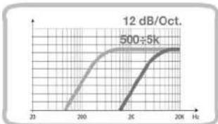
line
| Frequency (Hz) | Value | |---|---| | 20 | ~0 | | 250 | ~100 | | 300 | ~200 | | 350 | ~300 | | 400 | ~400 | | 450 | ~500 | | 500 | ~600 | | 550 | ~700 | | 600 | ~800 | | 650 | ~900 | | 700 | ~1000 | | 750 | ~1100 | | 800 | ~1200 | | 850 | ~1300 | | 900 | ~1400 | | 950 | ~1500 | | 1000 | ~1600 | | 1100 | ~1700 | | 1200 | ~1800 | | 1300 | ~1900 | | 1400 | ~2000 | | 1500 | ~2100 | | 1600 | ~2200 | | 1700 | ~2300 | | 1800 | ~2400 | | 1900 | ~2500 | | 2000 | ~2600 | | 2100 | ~2700 | | 2200 | ~2800 | | 2300 | ~2900 | | 2400 | ~3000 | | 2500 | ~3100 | | 2600 | ~3200 | | 2700 | ~3300 | | 2800 | ~3400 | | 2900 | ~3500 | | 3000 | ~3600 | | 3100 | ~3700 | | 3200 | ~3800 | | 3300 | ~3900 | | 3400 | ~4000 | | 3500 | ~4100 | | 3600 | ~4200 | | 3700 | ~4300 | | 3800 | ~4400 | | 3900 | ~4500 | | 4000 | ~4600 | | 4100 | ~4700 | | 4200 | ~4800 | | 4300 | ~4900 | | 4400 | ~5000 | | 4500 | ~5100 | | 4600 | ~5200 | | 4700 | ~5300 | | 4800 | ~5400 | | 4900 | ~5500 | | 5011 | ~5611 | | 5111 | ~5711 | | 5211 | ~5811 | | 5311 | ~5911 | | 5411 | ~6111 | | 5511 | ~6311 | | 5611 | ~6511 | | 5711 | ~6711 | | 5811 | ~6911 | | 5911 | ~7111 | | 6111 | ~7311 | | 6211 | ~7511 | | 6311 | ~7711 | | 6411 | ~7911 | | 6511 | ~8111 | | 6611 | ~8311 | | 6711 | ~8511 | | 6811 | ~8711 | | 6911 | ~8911 | | 7111 | ~9211 | | 7211 | ~9411 | | 7311 | ~9611 | | 7411 | ~9811 | | 7511 | ~9999 | | 7611 | ~9999 | | 7711 | ~9999 | | 7811 | ~9999 | | 7911 | ~9999 | | 8111 | ~9999 | | 8211 | ~9999 | | 8311 | ~9999 | | 8411 | ~9999 | | 8511 | ~9999 | | 8611 | ~9999 | | 8711 | ~9999 | | 8811 | ~9999 | | 8911 | ~9999 | | 9266 | ~9999 | | 9366 | ~9999 | | 9466 | ~9999 | | 9566 | ~9999 | | 9666 | ~9999 | | 9766 | ~9999 | | 9866 | ~9999 | | 9966 | ~9999 | | 12/Oct. (labeled) | - | The chart displays two data series: one for 'Value' and another for 'Value' over a range of frequencies from approximately -2 to +2 Hz. The values for 'Value' are explicitly labeled on the graph.62
B Channels
Config. 1, 2, 7, 8


Config. 3, 4, 9, 10


line
12 dB/Oct. | Frequency (Hz) | Value | | :--- | :--- | | 20 | ~0.8 | | 200 | ~1.0 | | 2K | ~1.0 | | 2K+ | ~1.0 |Config. 5, 6, 11, 12

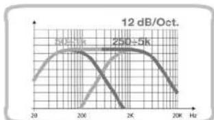
line
| Frequency (Hz) | 24.5K (dB/Oct.) | 250~5K (dB/Oct.) | |---|---|---| | 20 | ~0.8 | ~0.6 | | 200 | ~1.0 | ~0.9 | | 2K | ~0.7 | ~1.0 | | 20K | ~0.3 | ~0.6 |Config. 1, 3, 5, 7, 9, 11


63
LRx
The Universal Sound
audison
Owner's manual
LRx 3.1k
LRx 5.1k
Config. 2, 4, 6, 8, 10, 12


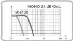
line
| Time (Hz) | Value | | --------- | ----- | | 20 | 50 | | 210 | 50 | | 220 | 50 |■ Subsonic SUB Channel (LRx 3.1k and LRx 5.1k)


line
| Time (Hz) | Value | | --------- | ----- | | 0 | 0 | | 20 | 20 | | 30 | 30 | | 200 | 30 | | 2K | 30 |■ Boost 50 Hz SUB Channel (LRx 3.1k and LRx 5.1k)

line
| Frequency (Hz) | Amplitude (dB) | |---|---| | 0 | 0 | | 40 | 3 | | 80 | 2 | | 120 | 0 | | 160 | 0 | | 200 | 0 | | 240 | 0 | | 280 | 0 | | 320 | 0 | | 360 | 0 | | 400 | 0 | | 440 | 0 | | 480 | 0 | | 520 | 0 | | 560 | 0 | | 600 | 0 | | 640 | 0 | | 680 | 0 | | 720 | 0 | | 760 | 0 | | 800 | 0 | | 840 | 0 | | 880 | 0 | | 920 | 0 | | 960 | 0 | | 1000 | 0 | | 1040 | 0 | | 1080 | 0 | | 1120 | 0 | | 1160 | 0 | | 1200 | 0 | | 1240 | 0 | | 1280 | 0 | | 1320 | 0 | | 1360 | 0 | | 1400 | 0 | | 1440 | 0 | | 1480 | 0 | | 1520 | 0 | | 1560 | 0 | | 1600 | 0 | | 1640 | 0 | | 1680 | 0 | | 1720 | 0 | | 1760 | 0 | | 1800 | 0 | | 1840 | 0 | | 1880 | 0 | | 1920 | 0 | | 1960 | 0 | | 2000 | 0 | | 2040 | 0 | | 2080 | 0 | | 2120 | 0 | | 2160 | 0 | | 2200 | 0 | | 2240 | 0 | | 2280 | 0 | | 2320 | 0 | | 2360 | 0 | | 2400 | 0 | | 2440 | 0 | | 2480 | 0 | | 2520 | 0 | | 2560 | 0 | | 2600 | 0 | | 2640 | 0 | | 2680 | 0 | | 2720 | 0 | | 2760 | 0 | | 2800 | 0 | | 2840 | 0 | | 2880 | 0 | | 2920 | 0 | | 2960 | 0 | | 3000 | 0 | | 3040 | 0 | | 3080 | 0 | | 3120 | 0 | | 3160 | 0 | | 3200 | 0 | | 3240 | 0 | | 3280 | 0 | | 3320 | 0 | | 3360 | 0 | | 3400 | 0 | | 3440 | 0 | | 3480 | 0 | | 3520 | 0 | | 3560 | 0 | | 3600 | 0 | | 3640 | 0 | | 3680 | 0 | | 3720 | 0 | | 3760 | 0 | | 3800 | 0 | | Note: The frequency values are estimated based on the provided code format. The chart is a single line graph with labels '±' indicating the frequency values for each curve. The y-axis label 'a' indicates the amplitude of the curve's value. There is no additional data series in this image. The label 'a' appears to be '±' or '±' above it.Installation
■ Amplifier fixing
For hidden installation the mounting holes for the screws are inside the amplifier outline. Secure the screws with the extended length screw driver bit provided with the amplifier.


65
LRx
The Universal Sound
audison
Owner's manual
LRx 3.1k
LRx 5.1k
■ Mounting template

A template is supplied to help you pre-plan the mounting of your amplifier. Printed on the template are instructions for flush or semi-embedded mounting, or for installing it on a flat surface. If you want to hide the cables, you can refer to the proper holes on the template.

natural_image
Technical line drawing of a mechanical component with no visible text or symbols■ Flush mounting

natural_image
Technical line drawing of a mechanical device with a 35-unit height dimension (no text or symbols)■ Semi-embedded mounting
natural_image
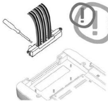
Technical illustration of a device with a screwdriver and warning symbol (no text or labels)You can connect the cables to ECI-H module before securing it to the amplifier.
Choose the module position and follow
the connection instructions you can find on
the labels. The amplifier must be off.
66

natural_image
Diagram of a device with coiled cable or wires inserted into a housing (no text or symbols visible)■ How to run the cables under the amplifier
If you use CONNECTION Audson interconnects, attach Y BLOCK on one of the mounting pins of the amplifier after plugging in RCA connectors.
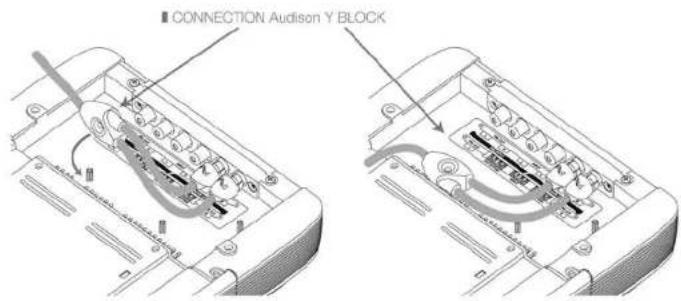
Route the cable in the proper location and secure it with the supplied clips.

To attach the clip, insert the tongue first, and then press until you hear a click.
LRx
The Universal Sound
audison
Owner's manual
LRx 3.1k
LRx 5.1k
LEDS




LRx
The Universal Sound
audison
Owner's manual
LRx 3.1k LRx 5.1k
Connection cables
For maximum performance, always use new, good quality cables; their outer jacket must not be spoiled, and the copper must not show oxidation. For proper operation, always consider the length of the connection, the load and the current it has to handle. CONNECTION Audison products are the most flexible and complete; they are designed and built in order to get the best out of every installation, especially when used with Audison amplifiers.
■ Speaker Cable
The table refers to continuous power into 4 Ohm load. If load decreases, cable size will have to increase proportionally.

heatmap
| Connection length | Applied power | Cable diameter | | :--- | :--- | :--- | | 0-1 | 3000 | 5 | | 0-1 | 2500 | 8 | | 0-1 | 2000 | 10 | | 0-1 | 1500 | 14 | | 0-1 | 1000 | 14 | | 0-1 | 500 | 14 | | 1-2 | 3000 | 5 | | 1-2 | 2500 | 8 | | 1-2 | 2000 | 10 | | 1-2 | 1500 | 14 | | 1-2 | 1000 | 14 | | 1-2 | 500 | 14 | | 2-3 | 3000 | 5 | | 2-3 | 2500 | 8 | | 2-3 | 2000 | 10 | | 2-3 | 1500 | 14 | | 2-3 | 1000 | 14 | | 2-3 | 500 | 14 | | 3-4 | 3000 | 5 | | 3-4 | 2500 | 8 | | 3-4 | 2000 | 10 | | 3-4 | 1500 | 14 | | 3-4 | 1000 | 14 | | 3-4 | 500 | 14 | | 4-5 | 3000 | 5 | | 4-5 | 2500 | 8 | | 4-5 | 2000 | 10 | | 4-5 | 1500 | 14 | | 4-5 | 1000 | 14 | | 4-5 | 500 | 14 | | 5-6 | 3000 | 5 | | 5-6 | 2500 | 8 | | 5-6 | 2000 | 10 | | 5-6 | 1500 | 14 | | 5-6 | 1000 | 14 | | 5-6 | 500 | 14 | | 6-7 | 3000 | 5 | | 6-7 | 2500 | 8 | | 6-7 | 2000 | 10 | | 6-7 | 1500 | 14 | | 6-7 | 1000 | 14 | | 6-7 | 500 | 14 | | 7-8 | 3000 | 5 | | 7-8 | 2500 | 8 | | 7-8 | 2000 | 10 | | 7-8 | 1500 | 14 | | 7-8 | 1000 | 14 | | 7-8 | 500 | 14 | The chart displays a heatmap with 'MW' as the primary variable on the Y-axis and 'Connection length' as the X-axis. The legend indicates 'Cable diameter' values: 'AWG' and 'W'. The data is grouped into four rows, each representing a separate row, and the columns represent the corresponding connection length. There are no additional data series or labels provided in the image.■ Power supply cable
If you don't know your system current consumption, find it using the mathematical formula below and find this same value on the left hand column of the table. Then calculate the length of your connection and find this same value on the bottom column of the table. At the point where these two values cross is the minimum section in gauge (A.W.G.) which CONNECTION recommends for building a high performance, reliable system.
How to calculate your system current consumption

I = Current consumption of your system in ampere (A);
TP = Total power (RMS) of channels of all amplifiers in your system;
Vbatt = Usually value is 12 V, the nominal automotive electrical system voltage.
Example:
- Your total system power (RMS) of all channels in all amplifiers is a combined 650 W.
- Your amplifier average is 50% efficiency, as most amplifiers today.
- Your electrical system is 12 Volt.
I = 650 × 212 = 108.3 A Current consumption
70

heatmap
| Cable Length (m) | 0-1 | 1-2 | 2-3 | 3-4 | 4-5 | 5-6 | 6-7 | 7-8 | |---|---|---|---|---|---|---|---|---| | 240-350 | | | | | | | | | | 180-240 | | | | | | | | | | 150-180 | | | | | | | | | | 120-150 | | | | | | | | | | 100-120 | | | | | | | | | | 80-100 | | | | | | | | | | 60-80 | | | | | | | | | | 40-60 | | | | | | | | | | 20-40 | | | | | | | | | | 8-20 | | | | | | | | | | 0-8 | | | | | | | | | *Current Draw I (A) | Power & Ground cable calculation table Tension: SAGAPOLIC recommendations for Methylated & FLOW Cables, SHAP/POWER cables where higher instantaneous current transfer. | Cable Size: AWL mm| | :---:---:---:---:---:---:---:---:---:---:---:---:---:---:---:---:---:---:---:---:---:---:---:---:---:---:---:---:---:---:---:---:---:---:---:---:---:---:---:---:---:---:---:---:---:---:---:---:---:---:---: | Cable Length (m) | | :---:---:---:---:---:---:---:---:---:---:---:---:---:---:---:---:---:---:---:---:---:---:---:---:---:---:---:---:---:---:---:---:---:---:---:---:---:---:---:---:---:---:---:---:---:---:---:---:--- | | *Current Draw I (A) | | Power & Ground cable calculation table Tension, SAGAPOLIC recommendations for Methylated & FLOW Cables, SHAP/POWER cables where higher instantaneous current transfer. | Power & Ground cable calculation table Tension, SAGAPOLIC recommendations for Methylated & FLOW Cables, SHAP/POWER cables where higher instantaneous current transfer. | Power & Ground cable calculation table Tension, SAGAPOLIC recommendations for Methylated & FLOW Cables, SHAP/POWER cables where higher instantaneous current transfer. | Power & Ground cable calculation table Tension, SAGAPOLIC recommendations for Methylated & FLOW Cables, SHAP/POWER cables where higher instantaneous current transfer. | Power & Ground cable calculation table Tension, SAGAPOLIC recommendations for Methylated & FLOW Cables, SHAP/POWER cables where higher instantaneous current transfer. | Power & Ground cable calculation table Tension, SAGAPOLIC recommendations for Methylated & FLOW Cables, SHAP/POWER cables where higher instantaneous current transfer. | Power & Ground cable calcification table Tension, SAGAPOLIC recommendations for Methylated & FLOW Cables, SHAP/POWER cables where higher instantaneous current transfer. | Power & Ground cable calcification table Tension, SAGAPOLIC recommendations for Methylated & FLOW Cables, SHAP/POWER cables where higher instantaneous current transfer. | Power & Ground cable calcification table Tension, SAGAPOLIC recommendations for Methylated & FLOW c - ShAP/POWER cables where higher instantaneous current transfer. | Power & Ground cable calcification table Tension, SAGAPOLIC recommendations for Methylated & FLOW c - ShAP/POWER cables where higher instantaneous current transfer. | Power & Ground cable calcification table Tension, SAGAPOLIC recommendations for Methylated & FLOW c - ShAP/POWER cables where higher instantaneous current transfer. | Power & Ground cable calcification table Tension, SAGAPOLIC recommendations for Methylated & FLOW c - ShAP/POWER cables where higher instantaneous current transfer. | Power & Ground cable calcification table Tension, SAGAPOLIC recommendations for Methylated & FLOW c - ShAP/POWER cables where higher instantaneous current transfer. | Power & Ground cable calcification table Tension, SAGAPOLIC recommendations for Methylated & FLOW c - ShAP/POWER cables where high level of current transfer. | Power & Ground cable calcification table Tension, SAGAPOLIC recommendations for Methylated & FLOW c - ShAP/POWER cables where high level of current transfer. | Power & Ground cable calcification table Tension, SAGAPOLIC recommendations for Methylated & FLOW c - ShAP/POWER cables where high level of current transfer. | Power & Ground cable calcification table Tension, SAGAPOLIIC recommendations for Methylated & FLOW c - ShAP/POWER cables where high level of current transfer. | Power & Ground cable calcification table Tension, SAGAPOLIIC recommendations for Methylated & FLOW c - ShAP/POWER cables where high level of current transfer. | Power & Ground cable calcification table Tension, SAGAPOLIIC recommendations for Methylated & FLOW c - ShAP/POWER cables which are lower in current transfer. | Power & Ground cable calcification table Tension, SAGAPOLIIC recommendations for Methylated & FLOW c - ShAP/POWER cables which are lower in current transfer. | Power & Ground cable calcification table Tension, SAGAPOLIIC recommendations for Methylated & FLOW c - ShAP/POWER cables which are lower in current transfer. | Power & Ground cable calcification table Tension, SAGPAMOIC recommendations for Methylated & FLOW c - ShAP/POWER cables which are lower in current transfer. | Power & Ground cable calcification table Tension, SAGPAMOIC recommendations for Methylated & FLOW c - ShAP/POWER cables which are lower in current transfer. | Power & Ground cable calcification table Tension, SAGPAMOIC recommendations for Methylated & FLOW c - ShAP/POWER cables that are lower in current transfer. | Power & Ground cable calcification table Tension, SAGPAMOIC recommendations for Methylated & FLOW c - ShAP/POWER cables that are lower in current transfer. | Power & Ground cable calcification table Tension, SAGPAMOIC recommendations for Methylated & FLOW c - ShAP/POWER cables that are lower in current transfer. | Power & Ground cable calcification table Tension, SAGPAMOIC recommendations for Methylated & FLOW c - ShAP/POWER cables that are lower in current transfer. | Power & Ground cable calcification table Tension, SAGPAMOIC recommendations for Methylated & FLOW c - ShAP/POWER cables that are lower in current transfer. | Power & Ground cable calcification table Tension, SAGPAMOIC recommendations for Methylated & FLOW c - SABPAMOIC recommendations for Methylated & FLOW c - ShAP/POWER cables that are lower in current transfer. | Power & Ground cable calcification table Tension, SAGPAMOIC recommendations for Methylated & FLOW c - ShAP/POWER cables that are lower in current transfer. | Power & Ground cable calcification table Tension, SAGPAMOIC recommendations for Methylated & FLOW c - ShAP / POWER calculation tables and lines of the current flow from the current flow to the current flow from the current flow to the current flow from the current flow to the current flow from the current flow to the current flow from the current flow to the current flow from the current flow to the current flow from the current flow to the current flow from the current flow to the current flow from the current flow to the current flow from the current flow to the current flow from the current flow to the current flow from the current flow to the current flow from the current flow to the current flow to the current flow from the current flow to the current flow from the current flow to the current flow from the current flow to the current flow from the current flow to the current flow from the current flow to the current flow from the current flow to the current flow from the current flow to the current flow from the current flow to the current flow from the current flow to the current flow from the current flow to the current flow from the current flow to the current flow from the current flow from the current flow to the current flow from the current flow to the current flow from the current flow to the current flow from the current flow to the current flow from the current flow to the current flow from the current flow to the current flow from the current flow to the current flow from the current flow to the current flow from the current flow to the current flow from the current flow to the current flow from the current flow to the current flow from the current flow to the current flow.Pattern
natural_image
Top-down cutaway view of a car showing internal components like wheels, sensors, and wiring (no text or labels)

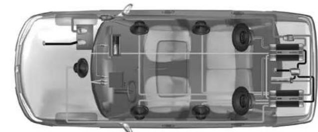
The Transfer System
Power Cable Ground Cable Speaker Cable
Subwoofer Cable Audio Interconnect Video Interconnect
1 BATTERY CLAMPS: ensure high current transfer without the power robbing consequences of a high resistance connection.
2 GROUND TERMINALS: minimize resistance and the consequent power losses associated with poor system grounding.
3 FUSE HOLDERS: are the first line of protection for your vehicle and yourself from dangerous short circuits. The high temperature case and waterproof construction ensure reliability in any environmental condition.
4 POWER & GROUND CABLES: are of fundamental importance to obtain reference performance in your car audio/video system. The special structure of Main Power and Power Flow cables minimize eddy current power losses and allow high instantaneous current transfer, enabling you to experience the full dynamics of your music.
5 FUSE DISTRIBUTION: their name tells you their function: transferring energy to electronic devices. They are available in various models, even modular, and they can house the protection fuse. Fuse distributions are to be used in every system where you need to transfer a huge amount of current without losses.
6 GROUND DISTRIBUTION BLOCKS: are as important as the power distribution to your systems overall performance. Solid, low resistance ground points prevent harmful voltage differences between components and improve high-level current transfer without power loss.
7 SUPERFARAD™: capacitors act as a "current reserve" storing DC energy for when your amplifiers demand it the most.
8 AUDIO INTERCONNECTS: are the first component in your system that audio signals pass through. For faithful reproduction, they must transfer these signals from the head-unit to the amplifiers without modifying the sound, while at the same time, reject the tremendous amount of noise radiated by on-board computer-controlled devices in your automobile.
9 VIDEO INTERCONNECTS: provide outstanding picture detail, definition and color balance. With constant 75-ohm impedance and outstanding shielding, stunning picture quality is assured.
10 SPEAKER CABLES: provide that last step in the faithful reproduction of your music. They ensure the transfer of music to your speakers without the coloration or degradation of the signal.
71
LRx
The Universal Sound
audison
Owner's manual
LRx 3.1k
LRx 5.1k
■ Audison logo in reverse


LRx
The Universal Sound
audison
Owner's manual
LRx 3.1k
LRx 5.1k
Patterns
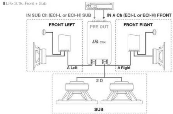
flowchart
graph TD
    A["IN SUB Ch (ECI-L or ECI-H) SUB"] --> B["FRONT LEFT"]
    A --> C["PRE OUT"]
    A --> D["FRONT RIGHT"]
    B --> E["A Left"]
    C --> F["A Right"]
    G["LRx 3.1k: Front + Sub"] --> H["Sub"]
    I["2Ω"] --> J["Sub"]

flowchart
graph TD
    A["IN A Ch (ECI-L or ECI-H) REAR"] --> B["FRONT LEFT"]
    C["IN B Ch (ECI-L or ECI-H) FRONT"] --> D["FRONT RIGHT"]
    B --> E["2 Ω"]
    D --> F["A Left"]
    D --> G["A Right"]
    E --> H["REAR LEFT"]
    E --> I["REAR RIGHT"]
    F --> J["SUB"]
    G --> K["SUB"]
■ LRx 3.1k: Front + Sub LRx 2.4: Rear

flowchart
graph TD
    A["IN SUB Ch (ECI-L or ECI-H) SUB"] --> B["FRONT LEFT"]
    A --> C["FRONT RIGHT"]
    B --> D["PRE OUT"]
    C --> E["PRE OUT Optional use"]
    D --> F["A Left"]
    E --> G["A Right"]
    F --> H["Parallel Connection 2 Ω"]
    G --> I["Parallel Connection 2 Ω"]
    J["SUB"] --> K["B Left"]
    J --> L["B Right"]
    K --> M["2 Ω"]
    L --> N["2 Ω"]
LRx
The Universal Sound
audison
Owner's manual
LRx 3.1k
LRx 5.1k

flowchart
graph TD
    A["IN SUB Ch (ECI-L or ECI-H) SUB"] --> B["PRE OUT Optional use"]
    B --> C["IN A Ch (ECI-L or ECI-H) FRONT"]
    D["FRONT LEFT"] --> E["Parallel Connection 2 Ω"]
    F["FRONT RIGHT"] --> G["Parallel Connection 2 Ω"]
    H["A Left"] --> I["A Right"]
    J["B Left"] --> K["B Right"]
    L["SUB"] --> M["2 Ω"]
    N["LRx 5.1k"] --> O["In Sub Ch (ECI-L or ECI-H) SUB"]

flowchart
graph TD
    A["LRx 5.1k: 3 way Multichannel + Sub"] --> B["IN SUB Ch (ECI-L or ECI-H) SUB"]
    B --> C["FRONT LEFT"]
    C --> D["PRE OUT Optional use"]
    D --> E["FRONT RIGHT"]
    E --> F["FRONT LEFT"]
    F --> G["FRONT RIGHT"]
    G --> H["Sub"]
    H --> I["2 Ω"]
    H --> J["2 Ω"]
    style A fill:#f9f,stroke:#333
    style B fill:#ccf,stroke:#333
    style C fill:#cfc,stroke:#333
    style D fill:#fcc,stroke:#333
    style E fill:#cff,stroke:#333
    style F fill:#ffc,stroke:#333
    style G fill:#cfc,stroke:#333
    style H fill:#fcc,stroke:#333
    style I fill:#ffc,stroke:#333
    style J fill:#cfc,stroke:#333
76
Technical specifications
Audison measurement standard
Power supply
| Voltage | 11÷15 VDC |
| Minimum idling current | 2.6 A |
| Idling current when off | 0.02 mA |
| Consumption @ 14.4 VDC(MAX musical power) | 99 A |
| Remote IN Voltage | 7÷15 VDC (1 mA) |
| Remote OUT Voltage | 12 VDC (50 mA) |
| Internal fuse (AFS) | 100 A |
Amplifier stage
| Distortion A,B Ch - THD (1 kHz @ 4 Ω) | 0.08% |
| Distortion SUB Ch - THD (100 Hz @ 4 Ω) | 0.5% |
| Bandwidth A,B Ch (-3 dB) | 4+62kHz |
| Bandwidth SUB Ch (-3 dB) | 7+800Hz |
| S/N A,B Ch ratio (weighted A @ 1 V) | 103 dB |
| S/N SUB Ch ratio (weighted A @ 1 V) | 87 dB |
| Damping factor A,B Ch (1 kHz @ 4 Ω) | 200 |
| Damping factor SUB Ch (100 Hz @ 4 Ω) | 110 |
| Input sensitivity (PRE IN) | 0.3+5 V |
| Input sensitivity (Speaker IN) | 1.4+24 V |
| Input impedance (FRE IN) | 15 kΩ |
| Input impedance (Speaker IN) | 5 kΩ |
Load impedance (MIN)
• 3 Ch (A + SUB Ch)
- 5 Ch (A + B + SUB Ch)
Nominal output power (RMS) PN @ 12 VDC:
A.B Ch THD 0.3%; SUB Ch THD 1%
Output power (BMS) @ 14.4 VDC: THD 1%
• 3Ch 2Ch×4Ω+1×4Ω 170W×2+750W
• 3Ch 2Ch×4Ω+1×2Ω 160W×2+1150W
• 3 Ch 2 Ch × 2 Ω + 1 × 4 Ω 250 W × 2 + 710 W
• 3Ch 2Ch×2Ω+1×2Ω 250W×2+1030W
- 5Ch ACh2×4Ω+BCh2×4Ω+1×4Ω
- 5 Ch A Ch2×4Ω + B Ch2×4Ω + 1×2Ω
- 5Ch ACh2×4Ω+BCh2×2Ω+1×2Ω
Inputs / Outputs / Filters
| IN A Ch | PRE / Speaker |
| IN B Ch | |
| IN SUB Ch | PRE / Speaker |
| OJT (Bypass) | PRE / Speaker |
| A Ch Filter (12 dB/Oct.) | Bypass / Hi-pass 50 ÷ 150 Hz |
| B Ch Filter (12 dB/Oct.) | |
| SUB Ch Filter (Mono 24 dB/Oct.) | Bypass / Lo-pass 50 ÷ 150 Hz |
| Subsonic | OFF/20/30 Hz @ 24 dB/Oct. |
| Boost 50 Hz | OFF / +2 dB / +4 dB |
| Sub remote volume control | +5 ± -5 dB |
Size
| B x L x H inches | 7"13/16 x 19"1/4 x 2"1/4 |
| Weight lb / kg | 11.02 / 5.0 |
LR5.1k
| 11÷15 VDC3 A0.02 mA110 A |
| 7÷15 VDC (1 mA)12 VDC (50 mA)100 A |
| 0.01%, 0.05%0.5%4÷62kHz7÷800Hz105 dB87 dB200860.3÷5 V1.4÷24 V15 kΩ5 kΩ |
2 × 4 + 2 × 2 + 1 × 2
45W×2+140W×2÷625W
60W×2+170W×2+750W
50W×2÷160W×2+1150W
50W × 2 ÷ 250W × 2 + 1030W
PRE / Speaker
PRE / Speaker
PRE / Speaker
PRE
Bypass/Hi 50 ÷ 5kHz
Bypass/Hi 50÷1k/Lo 250÷5kHz
Bypass/Lo 50 ÷ 150 Hz
OFF/20/30 Hz @ 24 dB/Oct.
OFF / +2 dB / +4 dB
+5÷-5dB
7"13/16×21"3/16×2"1/4
12.57 / 5.7
77
LR×3.1k

flowchart
graph TD
    A["PRE IN"] --> B["Hi-pass 12 dB/Oct. - Hz - 50-150"]
    C["PRE OUT"] --> D["Sub Sub 24 dB/Oct. - V - 0.3-6"]
    E["SUB IN"] --> F["Subsonic 24 dB/Oct. - V - 0.3-6"]
    G["SUB IN SUB"] --> H["Subsonic 24 dB/Oct. - V - 0.3-6"]
    B --> I["Filter 1: 2 ± 1"]
    D --> J["Filter 2: 2 ± 1"]
    F --> K["Filter 3: 2 ± 1"]
    H --> L["Filter 4: 2 ± 1"]
    I --> M["Level L/R 0.3-6"]
    J --> N["Level L/R 0.3-6"]
    K --> O["R"]
    L --> P["L"]
    M --> Q["R"]
    N --> R["L/R"]
    O --> S["OUT L/R"]
    P --> T["OUT L/R"]
    Q --> U["OUT L/R"]
    R --> V["OUT SUB"]
    T --> W["OUT SUB"]
    U --> X["VCA"]
    V --> X
    W --> X
    X --> Y["Subpass 24 dB/Oct. - Hz - 50-150"]
    Y --> Z["Filter 1: 2 ± 1"]
    Z --> AA["Filter 2: 2 ± 1"]
    AA --> AB["OUT SUB"]
    style A fill:#f9f,stroke:#333
    style C fill:#f9f,stroke:#333
    style E fill:#f9f,stroke:#333
    style G fill:#f9f,stroke:#333
    style B fill:#ccf,stroke:#333
    style D fill:#ccf,stroke:#333
    style F fill:#ccf,stroke:#333
    style H fill:#ccf,stroke:#333
    style J fill:#ccf,stroke:#333
    style K fill:#ccf,stroke:#333
    style L fill:#ccf,stroke:#333
    style M fill:#ccf,stroke:#333
    style N fill:#ccf,stroke:#333
    style O fill:#ccf,stroke:#333
    style P fill:#ccf,stroke:#333
    style Q fill:#ccf,stroke:#333
    style R fill:#ccf,stroke:#333
    style T fill:#ccf,stroke:#333
    style U fill:#ccf,stroke:#333
    style V fill:#ccf,stroke:#333
NON INDEPENDENT FREQUENCY CONTROL INDEPENDENT FREQUENCY CONTROL HI-PASS LO-PASS BANDPASS NON INVERTED AMPLIFIES INVERTED AMPLIFIER STEREO SIGNAL
LR×5.1k

flowchart
graph TD
    A["PRE IN"] --> B["L N S"]
    B --> C["LEVEL A Ch"]
    C --> D["HI-pass 12 dB/Oct. - Hz - RANGE 50-500 x1 500-5k x10"]
    D --> E["HI-pass 2/3/4/1"]
    E --> F["L OUT A"]
    E --> G["R OUT B"]

    H["PRE IN/OUT"] --> I["L R"]
    I --> J["L N S"]
    J --> K["B Input"]
    K --> L["LEVEL B Ch"]
    L --> M["HI-pass 12 dB/Oct. - Hz - 50-1k"]
    M --> N["Lo pass 12 dB/Oct. - Hz - 250-5k"]
    N --> O["Filter 2/3/4/1"]
    O --> P["L OUT B"]
    O --> Q["R OUT B"]

    R["PRE IN SUB"] --> S["L N S"]
    S --> T["MIX L+R"]
    T --> U["SUB Input"]
    U --> V["Level SUB"]
    V --> W["VCA"]
    W --> X["Subsonic 24 dB/Oct. 20-30 Hz"]
    X --> Y["Subsonic 28/36 Hz"]
    Y --> Z["50 Hz 2 dB - 4 dB"]
    Z --> AA["Reset 40 Hz 7.6 dB/3.2 dB/1"]
    AA --> AB["Lo pass 24 dB/Oct. - Hz - 50-150"]
    AB --> AC["Filter 2/3/4/1"]
    AC --> AD["OUT SUB"]

    style A fill:#f9f,stroke:#333
    style H fill:#f9f,stroke:#333
    style R fill:#f9f,stroke:#333
NON INDEPENDENT FREQUENCY CONTROL INDEPENDENT FREQUENCY CONTROL HI-PASS LO-PASS BANDPASS NON INVERTED AMPLIFIER INVERTED AMPLIFIER STEREO SIGNAL

- Introduzione
- B Channels
- Installazione
- CEA 2006 Specifications
- LRx 3.1k
- LRx 5.1k
- Audison measurement standard
- Power measures taken according to Audison standard, 2005 edition
- audison
- Introduction
- Table of contents
- Packing contents
- SAFE SOUND
- ECI - Easy Common Interface Modules
- ■ LRx 3.1k ECI - L Low Level: Pre-amplified Input/Output module
- ■ LRx 3.1k ECI - H High Level: High Level Input/PRE Output module
- ■ LRx 5.1k ECI - L Low Level: Pre-amplified Input/Output module
- ■ LRx 5.1k ECI - H High Level: High Level Input/PRE Output module
- ■ ECI module installation
- ■ LRx 3.1k When mounting ECI in reverse
- ■ LRx 5.1k When mounting ECI in reverse
- Power supply/Outputs/Other functions Panel
- ■ LRx 3.1k Power Supply and output terminal description
- ■ LRx 5.1k Power Supply and output terminal description
- ■ How to change the plate
- ■ Examples of how to use the plates
- ■ How to mount fast-on taker connectors
- Control panel
- Configuration
- Filter
- CHANNELS
- Installation
- ■ How to run the cables under the amplifier
- Connection cables
- ■ Speaker Cable
- ■ Power supply cable
- Technical specifications
Brand : AUDISON
Model : LRx 3.1k
Category : Receiver