
PV 6 - Blender PEAVEY - Free user manual and instructions
Find the device manual for free PV 6 PEAVEY in PDF.


| Product Type | Compact Mixer |
| Model | PV 6 |
| Brand | Peavey |
| Dimensions | 7.25 x 11.4 x 2.1875 in (18.42 x 28.96 x 5.56 cm) |
| Weight | 3.99 lb (1.81 kg) |
| Power Supply | External 15 VDC, 1 A adapter; 100-240 VAC 50/60 Hz, 15 W |
| Number of Channels | 6 channels: 2 mono (mic/line) + 2 stereo (3/4) + 2 stereo (5/6) |
| Mic Preamps | 2 Silencer™ preamps with 0.0007% THD, EIN -126 dBu |
| Phantom Power | Global 48 V switchable |
| EQ | 3-band shelving EQ per channel (High: ±15 dB @ 12 kHz, Low: ±15 dB @ 80 Hz); Mid-Morph on channels 1 & 2 (cut at 250 Hz, boost at 4 kHz) |
| EQ Bypass | On mic channels (1 & 2) |
| Compressor | Built-in stereo compressor with enable switch, threshold control, ratio approx. 4:1 |
| Effects | None (EFX send to external processor); EFX master level control and balanced 1/4" output |
| Direct Outputs | 2 channels of 1/4" TRS direct out (after preamp) |
| USB Connectivity | USB Type B: stereo streaming audio in/out (16-bit, 44.1/48 kHz) to computer |
| Main Outputs | 1/4" balanced TRS left/right |
| Control Room Outputs | Dual selectable (A/B) with RCA connectors and level control |
| Headphone Output | 1/4" TRS stereo, studio quality with level control |
| Additional Inputs | Stereo 3.5mm, RCA, and 1/4" on channel 5/6; channel 1 has 1 MΩ guitar input with Pre-Shape switch |
| Metering | 6-segment LED master meter bridge (-18 dBu to +19 dBu) |
| Warranty | 2 years (plus 3 additional years if warranty card registered within 90 days) |
| Construction | Rugged console design with steel chassis |
Frequently Asked Questions - PV 6 PEAVEY
User questions about PV 6 PEAVEY
0 question about this device. Answer the ones you know or ask your own.
Ask a new question about this device
Download the instructions for your Blender in PDF format for free! Find your manual PV 6 - PEAVEY and take your electronic device back in hand. On this page are published all the documents necessary for the use of your device. PV 6 by PEAVEY.
USER MANUAL PV 6 PEAVEY
PV ^® 6·PV ^® 6BT
Compact Mixer
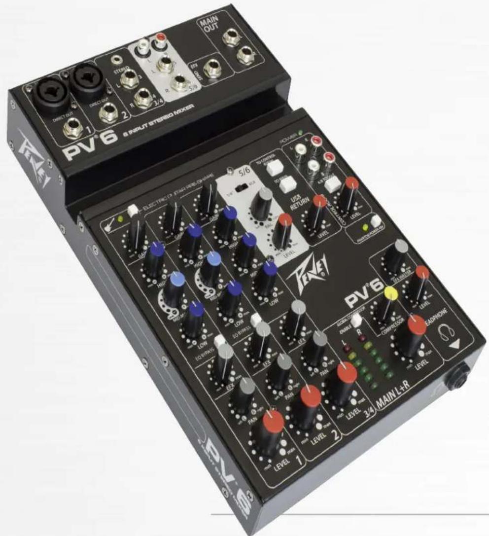
Operating Manual
FC
FCC/ICES Compliancy Statement
Warning: Changes or modifications to the equipment not approved by Peavey Electronics Corp. can void the user's authority to use the equipment.
Note – This equipment has been tested and found to comply with the limits for a Class B digital device, pursuant to Part 15 of the FCC Rules. These limits are designed to provide reasonable protection against harmful interference in a residential installation. This equipment generates, uses, and can radiate radio frequency energy and, if not installed and used in accordance with the instructions, may cause harmful interference to radio communications. However, there is no guarantee that interference will not occur in a particular installation. If this equipment does cause harmful interference to radio or television reception, which can be determined by turning the equipment off and on, the user is encouraged to try and correct the interference by one or more of the following measures.
• Reorient or relocate the receiving antenna.
- Increase the separation between the equipment and receiver.
- Consult the dealer or an experienced radio/TV technician for help.
- Connect the equipment into an outlet on a circuit different from that to which the receiver is connected.
Caution
The equipment complies with FCC radiation exposure limits set forth for an uncontrolled environment.

Peavey Electronics Corporation • 5022 Hartley Peavey Drive • Meridian, MS • 39305
Introducing the next level in world class non-powered mixer performance. The all new PV series mixing consoles include Peavey's reference-quality mic preamps that deliver an incredible 0.0007% THD, making the PV series mixers excellent for live or recording applications. The PV 6 BT includes 2 channels of reference-quality mic preamps, 2 direct outputs for recording, 2 stereo channels, media channel with Bluetooth wireless input, high quality digital effects, streaming USB out, 48 volt phantom power, dual selectable control room outputs, compression, one channel of on board selectable guitar preamp, 3-band EQ per channel with bypass, effects level per channel, signal clip indicators, and a stereo master LED meter bridge. This amazingly versatile mixer is at home both in the studio as well as live applications. Its modern features such as Bluetooth allow seamless connection to almost any "smart" device. Direct outs allow easy connection to most DAW interfaces for recording; in addition, the PV 6 BT can stream audio directly to a PC. EQ bypass allows the user to compare the EQ'd signal to the original signal with the push of a button. Compression keeps signals with difficult levels under control, and Peavey's exclusive guitar-shape adjusts the EQ and preamp specifically for guitar. The all new PV series mixers represent the pinnacle of performance and value. Combine Peavey's legendary reliability with our 5 year warranty, and you can be assured of years of quality reliable service!
FEATURES (both models):
- 2 Combination 1/4'' balanced / XLR inputs feeding Silencer™ preamps
- Stereo 1/4"/ 3.5mm input channel with input gain, EQ, Effects send and Pan / Balance
- Switchable 1/4" / RCA (/ Bluetooth PV6 BT only) stereo input with input balance and level control
• 3-band EQ on all channels
• 2 Channels of Peavey's Exclusive Mid-Morph
• LED clip and signal present indication
• EQ Bypass on mic channels
• Dual selectable control room outputs
• Global 48V phantom power - 1/4" balanced Main stereo outputs
• Rugged console design
• Built-in stereo compressor with enable switch - Stereo pan control per channel
• 2 Channels of direct out - Stereo USB-B streaming audio in and out
• High quality master LED meter bridge
• Studio quality headphone output - Peavey's exclusive on-board 1 Meg guitar input
• Control room output with level control
• Electric Guitar Pre-Shape switch
• External universal input power supply
PV6BT ADDITIONAL FEATURES:
- Bluetooth wireless stereo audio input
- Efx Mute switch
PV6 ONLY:
- Efx master level feeding balanced 1/4" output

Installation Note:
This unit must have the following clearances from any combustible surface: top: 8", sides: 12", back: 12"
Electric Guitar Pre-Shape
Engaging this button optimizes the on board equalization for guitar.
Signal Presence/Clip LED
This LED helps in setting the gain control. Gain (3) should be adjusted so that the green LED flashes in time with the source, and turns red only on the loudest peaks. If adding EQ results in clipping (red LED), compensate here by reducing gain (3). The red clipping LED lights when roughly 5dB of headroom remains.
Gain
The Input Gain control is used to establish proper gain structure in the channel. The input gain can be adjusted over a wide range to compensate for soft voices or very loud drums. To maximize the signal-to-noise ratio, the gain should be set to the proper level, with the Level Knob (10) set to 0. If the clip LED comes on and remains lit, try reducing the gain.
High EQ
This High EQ shelving type of active tone control varies the treble frequencies (+/- 15 dB at 12 kHz) and is designed to remove noise or add brilliance to the signal, depending on the quality of the source.
Mid EQ
Where most mid-range controls work at just one frequency, the Mid-Morph works at two. When turned counterclockwise, it cuts at 250 Hz to reduce frequencies that muddy the sound. When turned clockwise, it boosts at 4 kHz to add intelligibility to vocals. Either way, improved vocal or instrument definition can be achieved.
Low EQ
A shelving type of EQ that varies the bass frequency levels (+/- 15 dB at 80 Hz). Low EQ adds depth to thin-sounding signals or cleans up the muddy ones. As with any EQ, use sparingly. Too much of this EQ can give you a booming bottom end. Caution: Excessive low frequency boost causes greater power consumption and increases the possibility of speaker damage.
EQ Bypass
Engaging this button bypasses the equalization of the channel.
EFX Send
This control adjusts the level of the channel signal added to the effects mix. The signal is sent to the internal effects processor (PV6 BT) or the EFX send jack (PV6). Turning the knob to the left (min) will turn off effects on the associated channel, while turning the knob to the right will increase the amount of the selected effect.
Pan
This knob controls the placement of the signal in the stereo field. When rotated completely counterclockwise, the signal is present only on the left channel; when rotated completely clockwise, only in the right channel. This control functions as a balance control to adjust the relative level of the left and right signals on stereo channels.
Channel Level
This controls the output level of the channel into the main mix. The gain is 0 dB when set to the detent at mid-rotation (12:00). 10 dB of boost is available at the max gain setting. Normal operation is to start with this knob at the detent, and set the input gain and EQ with the source playing such that normal levels are seen at the bicolor LED and the main meter array. As additional sources are added, it is normal to turn this knob down slightly.

Signal Presence/Clip LED
This LED helps in setting the gain control. Gain (3) should be adjusted so that the green LED flashes in time with the source, and turns red only on the loudest peaks. If adding EQ results in clipping (red LED), compensate here by reducing gain (3). The red clipping LED lights when roughly 5dB of headroom remains.
Gain
The Input Gain control is used to establish proper gain structure in the channel. The input gain can be adjusted over a wide range to compensate for soft voices or very loud drums. To maximize the signal-to-noise ratio, the gain should be set to the proper level, with the Level Knob (10) set to 0. If the clip LED comes on and remains lit, try reducing the gain.
High EQ
This High EQ shelving type of active tone control varies the treble frequencies (+/- 15 dB at 12 kHz) and is designed to remove noise or add brilliance to the signal, depending on the quality of the source.
Mid EQ
This midrange control adjusts the stereo channel's eq +/-20 dB @ 440Hz
Low EQ
A shelving type of EQ that varies the bass frequency levels (+/- 15 dB at 80 Hz). Low EQ adds depth to thin-sounding signals or cleans up the muddy ones. As with any EQ, use sparingly. Too much of this EQ can give you a booming bottom end. Caution: Excessive low frequency boost causes greater power consumption and increases the possibility of speaker damage.
EQ Bypass
Engaging this button bypasses the equalization of the channel.
EFX Send
This control adjusts the level of the channel signal added to the effects mix. The signal is sent to the internal effects processor (PV6 BT) or the EFX send jack (PV6). Turning the knob to the left (min) will turn off effects on the associated channel, while turning the knob to the right will increase the amount of the selected effect.
Pan
This knob controls the placement of the signal in the stereo field. When rotated completely counterclockwise, the signal is present only on the left channel; when rotated completely clockwise, only in the right channel. This control functions as a balance control to adjust the relative level of the left and right signals on stereo channels.
Channel Level
This controls the output level of the channel into the main mix. The gain is 0 dB when set to the detent at mid-rotation (12:00). 10 dB of boost is available at the max gain setting. Normal operation is to start with this knob at the detent, and set the input gain and EQ with the source playing such that normal levels are seen at the bicolor LED and the main meter array. As additional sources are added, it is normal to turn this knob down slightly.

flowchart
graph TD
    A["MIN MAX"] --> B["GAIN"]
    B --> C["0"]
    C --> D["MIN -k"]
    D --> E["+"]
    E --> F["HIGH"]
    F --> G["0"]
    G --> H["MIN -k"]
    H --> I["+"]
    I --> J["MID"]
    J --> K["0"]
    K --> L["MIN -k"]
    L --> M["+"]
    M --> N["LOW EQ BYPASS"]
    N --> O["min -k"]
    O --> P["EFX"]
    P --> Q["0"]
    Q --> R["left right R"]
    R --> S["PAN"]
    S --> T["min -k"]
    T --> U["+"]
    U --> V["LEVEL 3/4"]
    V --> W["2"]
    V --> X["3"]
    V --> Y["4"]
    V --> Z["5"]
    V --> AA["6"]
    V --> AB["8"]
    V --> AC["9"]
    V --> AD["10"]
PV®6 Front Panel
11 Two-way Audio Input Selector
Allows you to select between a 1/4" and RCA audio input.
12Balance
Adjusts relative levels of left and right channels.
13 Level
Adjusts the level of the source selected by (11).
14 Global Compressor Enable Button
When depressed, the compressor is enabled.
15 LED Meters
Two six-segment LED arrays are provided to monitor the levels of the main left/right outputs. These meters range from -18 dBu to +19dBu. The highest green LED corresponds to +4 dBu at the outputs.
16 Digital Return Level
Controls the signal level coming in to the USB digital audio port, typically from a USB-equipped computer. The nominal setting is near 12:00 for this control.
17 To Control Room
When depressed, USB digital audio return is routed to the control room and headphone outputs. Use this setting when recording with DAW software to avoid unintended loops.
(18) To Main
When depressed, USB digital audio return is routed to the Main summing amp. This setting is recommended only when there is a requirement to playback through the main outputs, at which time the DAW software must have input monitoring disabled.

Beware of creating an unintended loop, which results in very LOUD and uncontrolled oscillation that can damage loudspeakers and eardrums!
(19)RCA Connectors for Monitor
Connect powered monitors, or an amplifier feeding monitor speakers here. Set the volume controls on the monitors A and B to be equal when the A/B switch is toggled. The signal sent to this output is normally the Left/Right mix. When the "To Control Room" switch (17) is engaged, the USB return signal is also sent to the Monitor Outputs.
20 A/B Toggle Switch
When depressed, the A outputs are muted and the B outputs are on. When raised, the A outputs are on and the B outputs are muted. This allows the easy checking of a computer DAW mix on two different sets of monitors.
(21)Monitor Level
Use this control to set the listening level in your control room monitors. The optimum setting for this control is 12:00, so monitor amplifier levels (or powered monitor levels) should be adjusted with this knob at 12:00. There is an additional 17 dB of gain available on this pot at the max position.
(22) Phantom Power
This Switch applies +48 VDC voltage to the input XLR connectors to power microphones requiring phantom power.

If phantom power is used, do not connect unbalanced dynamic microphones or other devices to the XLR inputs that cannot handle this Voltage.

flowchart
graph TD
    A["16 17 18"] --> B["TO CONTROL ROOM"]
    B --> C["TO MAIN"]
    C --> D["DIGITAL RETURN"]
    D --> E["LEVEL LEVEL"]
    E --> F["L A R"]
    F --> G["A/B TOGGLE"]
    G --> H["CONTROL ROOM"]
    H --> I["PHANTOM POWER 48V"]
    I --> J["20"]
    J --> K["19"]
    L["11"] --> M["5/6"]
    N["12"] --> M
    O["13"] --> M
    P["14"] --> Q["PV6"]
    R["15"] --> Q
    S["25"] --> T["MAIN L+R"]
    U["26"] --> T
    V["27"] --> W["HEADPHONE"]
    X["23"] --> Y["LEVEL"]
    Z["24"] --> AA["EFX MASTER"]
    AB["22"] --> AC["PHANTOM POWER 48V"]
    AD["21"] --> AE["CONTROL ROOM"]
    AF["19"] --> AG["A/B TOGGLE"]
PV®6 Front Panel
23 EFX Level
This is the master output level control for the EFX mix. The output level sent to the EFX Send jack is controlled by the Channel Level Control (10), the channel EFX Send controls (8), and by this master control. The 12:00 position is the recommended setting for this control.
24 Headphone Level
This knob sets the headphone and control room output levels. To avoid damage to your hearing, make sure to turn the dial fully counterclockwise before using headphones. Slowly turn the knob clockwise until you reach a comfortable listening level.
25 Compressor Control
Adjusting this knob clockwise lowers the threshold of the compressor, thereby increasing the amount of compression. The compressor ratio is in the 4:1 range, varying with signal levels and the amount of compression. This is useful for controlling peak levels from live sources. The compressor is after the master level control(26), and before the main outs (35) and the USB port(39), so it can be used to tame vocals being recorded into a DAW. You can audition the effect of the compressor by switching it in and out with the Enable switch (14). When the compressor is active, the adjacent red LED will illuminate.
26 Level
This is the master level control, which controls the overall level sent to the main outputs (35) and the USB port (39).
27 Headphone Output
The Headphone Output is a 1/4" TRS (Tip= Left; Ring = Right; Sleeve = Ground) jack. The signal sent to this output is normally the Left/Right mix. When the "To Control Room" switch (17) is engaged, the USB return signal is also sent to the headphones.
PV®6BT Front Panel
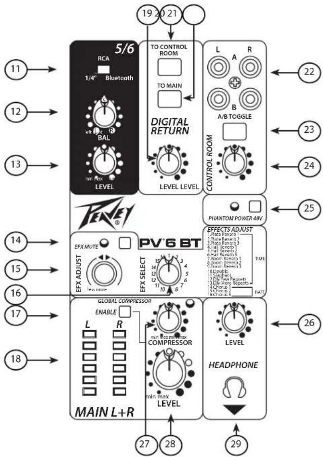
11 Three-way Audio Input Selector
Allows you to select between a 1/4", RCA audio input, or Bluetooth connection.
12 Balance
Adjusts relative levels of left and right channels.
13 Level
Adjusts the level of the source selected by (11).
(14) EFX Mute
Depressing this button will cut all digital effects from the main mix.
15 EFX Adjust
This rotary encoder adjusts the parameter of the effect selected by EFX SELECT (16). For reverbs, double, slapback, and delays, the knob controls the time. For chorus effects, this knob controls the rate. Any adjustment you make with this knob will be stored into memory until the next time you adjust the parameter. In other words, your changes will "stick" even if you select a different effect. When you return, things will be the way you left them.
(16) EFX SELECT
Use this rotary encoder to choose which effect you want to apply. There are 9 reverbs, 4 delays, and 3 chorus effects. You can fine-tune the behavior of the selected effect with the EFX ADJUST knob.
⑰ Global Compressor Enable Button
When depressed, the compressor is enabled.
18 LED Meters
Two six-segment LED arrays are provided to monitor the levels of the main left/right outputs. These meters range from -18 dBu to +19dBu. The highest green LED corresponds to +4 dBu at the outputs.
19 Digital Return Level
Controls the signal level coming in to the USB digital audio port, typically from a USB-equipped computer. The nominal setting is near 12:00 for this control.
20 To Control Room
When depressed, USB digital audio return is routed to the control room and headphone outputs. Use this setting when recording with DAW software to avoid unintended loops.
②1 To Main
When depressed, USB digital audio return is routed to the Main summing amp. This setting is recommended only when there is a requirement to playback through the main outputs, at which time the DAW software must have input monitoring disabled.

Beware of creating an unintended loop, which results in very
LOUD and uncontrolled oscillation that can damage loudspeakers and eardrums!
flowchart
graph TD
    A["19 20 21"] --> B["TO CONTROL ROOM"]
    B --> C["TO MAIN"]
    C --> D["DIGITAL RETURN"]
    D --> E["LEVEL LEVEL"]
    E --> F["CONTROL ROOM"]
    F --> G["L A R"]
    G --> H["B A/B TOGGLE"]
    H --> I["PHANTON POWER 48V"]
    I --> J["EFFECTS ADJUST"]
    J --> K["TIME"]
    K --> L["HEADPHONE"]
    L --> M["LEVEL"]
    M --> N["HEADPHONE"]
    N --> O["HEADPHONE"]
    O --> P["HEADPHONE"]
    P --> Q["HEADPHONE"]
    Q --> R["HEADPHONE"]
    R --> S["HEADPHONE"]
    S --> T["HEADPHONE"]
    T --> U["HEADPHONE"]
    U --> V["HEADPHONE"]
    V --> W["HEADPHONE"]
    W --> X["HEADPHONE"]
    X --> Y["HEADPHONE"]
    Y --> Z["HEADPHONE"]
    Z --> AA["HEADPHONE"]
    AA --> AB["HEADPHONE"]
    AB --> AC["HEADPHONE"]
    AC --> AD["HEADPHONE"]
    AD --> AE["HEADPHONE"]
    AE --> AF["HEADPHONE"]
    AF --> AG["HEADPHONE"]
    AG --> AH["HEADPHONE"]
    AH --> AI["HEADPHONE"]
    AI --> AJ["HEADPHONE"]
    AJ --> AK["HEADPHONE"]
    AK --> AL["HEADPHONE"]
    AL --> AM["HEADPHONE"]
    AM --> AN["HEADPHONE"]
    AN --> AO["HEADPHONE"]
    AO --> AP["HEADPHONE"]
    AP --> AQ["HEADPHONE"]
    AQ --> AR["HEADPHONE"]
    AR --> AS["HEADPHONE"]
    AS --> AT["HEADPHONE"]
    AT --> AU["HEADPHONE"]
    AU --> AV["HEADPHONE"]
    AV --> AW["HEADPHONE"]
    AW --> AX["HEADPHONE"]
    AX --> AY["HEADPHONE"]
    AY --> AZ["HEADPHONE"]
    AZ --> BA["HEADPHONE"]
    BA --> BB["HEADPHONE"]
    BB --> BC["HEADPHONE"]
    BC --> BD["HEADPHONE"]
    BD --> BE["HEADPHONE"]
    BE --> BF["HEADPHONE"]
    BF --> BG["HEADPHONE"]
    BG --> BH["HEADPHONE"]
    BH --> BI["HEADPHONE"]
    BI --> BJ["HEADPHONE"]
    BJ --> BK["HEADPHONE"]
    BK --> BL["HEADPHONE"]
    BL --> BM["HEADPHONE"]
    BM --> BN["HEADPHONE"]
    BN --> BO["HEADPHONE"]
    BO --> BP["HEADPHONE"]
    BP --> BQ["HEADPHONE"]
    BQ --> BR["HEADPHONE"]
    BR --> BS["HEADPHONE"]
PV®6BT Front Panel
22 RCA Connectors for Monitor
Connect powered monitors, or an amplifier feeding monitor speakers here. Set the volume controls on the monitors A and B to be equal when the A/B switch is toggled. The signal sent to this output is normally the Left/Right mix.
When the "To Control Room" switch (20) is engaged, the USB return signal is also sent to the Monitor Outputs.
23 A/B Toggle Switch
When depressed, the A outputs are muted and the B outputs are on. When raised, the A outputs are on and the B outputs are muted. This allows the easy checking of a computer DAW mix on two different sets of monitors.
24 Monitor Level
Use this control to set the listening level in your control room monitors. The optimum setting for this control is 12:00, so monitor amplifier levels (or powered monitor levels) should be adjusted with this knob at 12:00. There is an additional 17 dB of gain available on this pot at the max position.
25 Phantom Power
This Switch applies +48 VDC voltage to the input XLR connectors to power microphones requiring phantom power.

If phantom power is used, do not connect unbalanced dynamic microphones or other devices to the XLR inputs that cannot handle this Voltage.
26 Headphone Level
This knob sets the headphone and control room output levels. To avoid damage to your hearing, make sure to turn the dial fully counterclockwise before using headphones. Slowly turn the knob clockwise until you reach a comfortable listening level.
27 Compressor Control
Adjusting this knob clockwise lowers the threshold of the compressor, thereby increasing the amount of compression. The compressor ratio is in the 4:1 range, varying with signal levels and the amount of compression. This is useful for controlling peak levels from live sources. The compressor is after the master level control (28), and before the main outs (36) and the USB port(39), so it can be used to tame vocals being recorded into a DAW. You can audition the effect of the compressor by switching it in and out with the Enable switch (14). When the compressor is active, the adjacent red LED will illuminate.
28 Level
This is the master level control, which controls the overall level sent to the main outputs (36) and the USB port (39).
29 Headphone Output
The Headphone Output is a 1/4" TRS (Tip= Left; Ring = Right; Sleeve = Ground) jack. The signal sent to this output is normally the Left/Right mix. When the "To Control Room" switch (20) is engaged, the USB return signal is also sent to the headphones.

flowchart
graph TD
    A["Main OUT"] --> B["Digital"]
    B --> C["30"]
    B --> D["32"]
    B --> E["35"]
    F["1/4"H6-Z"] --> G["1"]
    H["1/4"H6-Z"] --> I["2"]
    J["1/4"H6-Z"] --> K["3"]
    L["1/4"H6-Z"] --> M["4"]
    N["1/4"H6-Z"] --> O["5/6"]
    P["1/4"H6-Z"] --> Q["6"]
    R["1/4"H6-Z"] --> S["7"]
    T["1/4"H6-Z"] --> U["8"]
    V["1/4"H6-Z"] --> W["9"]
    X["1/4"H6-Z"] --> Y["10"]
    Z["1/4"H6-Z"] --> AA["11"]
    AB["1/4"H6-Z"] --> AC["12"]
    AD["1/4"H6-Z"] --> AE["13"]
    AF["1/4"H6-Z"] --> AG["14"]
    AH["1/4"H6-Z"] --> AI["15"]
    AJ["1/4"H6-Z"] --> AK["16"]
    AL["1/4"H6-Z"] --> AM["17"]
    AN["1/4"H6-Z"] --> AO["18"]
    AP["1/4"H6-Z"] --> AQ["19"]
    AR["1/4"H6-Z"] --> AS["20"]
    AT["1/4"H6-Z"] --> AU["21"]
    AV["1/4"H6-Z"] --> AW["22"]
    AX["1/4"H6-Z"] --> AY["23"]
    AZ["1/4"H6-Z"] --> BA["24"]
    BB["1/4"H6-Z"] --> BC["25"]
    BD["1/4"H6-Z"] --> BE["26"]
    BF["1/4"H6-Z"] --> BG["27"]
    BH["1/4"H6-Z"] --> BI["28"]
    BJ["1/4"H6-Z"] --> BK["29"]
    BL["1/4"H6-Z"] --> BM["30"]
    BN["1/4"H6-Z"] --> BO["31"]
    BP["1/4"H6-Z"] --> BQ["32"]
    BR["1/4"H6-Z"] --> BS["33"]
    BT["1/4"H6-Z"] --> BU["34"]
28 MIC/LINE INPUT
This combination input jack can accept either a 1/4" (balanced or unbalanced) input or a XLR balanced, low-impedance connection. The tip is positive on the 1/4" balanced input, and pin 2 is positive on the XLR. When ELECTRIC GUITAR PRE-SHAPE is depressed, the channel 1 1/4" input changes to a high impedance (1 MegΩ), like a 12AX7 vacuum tube guitar amplifier input.
29 1/4" TRS Direct Outs
Impedance-balanced outputs fed by the mic preamp. Channel 1 output is after the ELECTRIC GUITAR PRE-SHAPE switch.
30 Stereo 3.5mm Input
Accept a stereo input from the output of an MP3 player, CD player, tape deck or other similar device. This input is optimized for portable handheld devices and therefore has very high sensitivity.
31 Stereo Inputs
Channels 3 and 4 feature stereo inputs via 1/4" jack. If only one jack is used, it behaves as a mono source with a pan control. Once both jacks are connected, it behaves as a stereo source with a balance control; 3 is Left and 4 is Right.
32 RCA Connection
Accept a stereo input from the output of an MP3 player, CD player, tape deck or other similar device. This input is optimized for portable handheld devices and therefore has very high sensitivity.
33 Stereo
Accept a stereo input from the output of an MP3 player, CD player, tape deck or other similar device. This input is optimized for portable handheld devices and therefore has very high sensitivity.
34 EFX Send
Ground compensated TRS balanced output fed by the EFX SEND master level (23). These outputs can be used with Tip Ring Sleeve (TRS) balanced or Tip Sleeve (TS) unbalanced connectors.
35 Main Out
Ground compensated TRS balanced outputs fed by the master LEVEL control (26). These outputs can be used with Tip Ring Sleeve (TRS) balanced or Tip Sleeve (TS) unbalanced connectors.
30 MIC/LINE INPUT
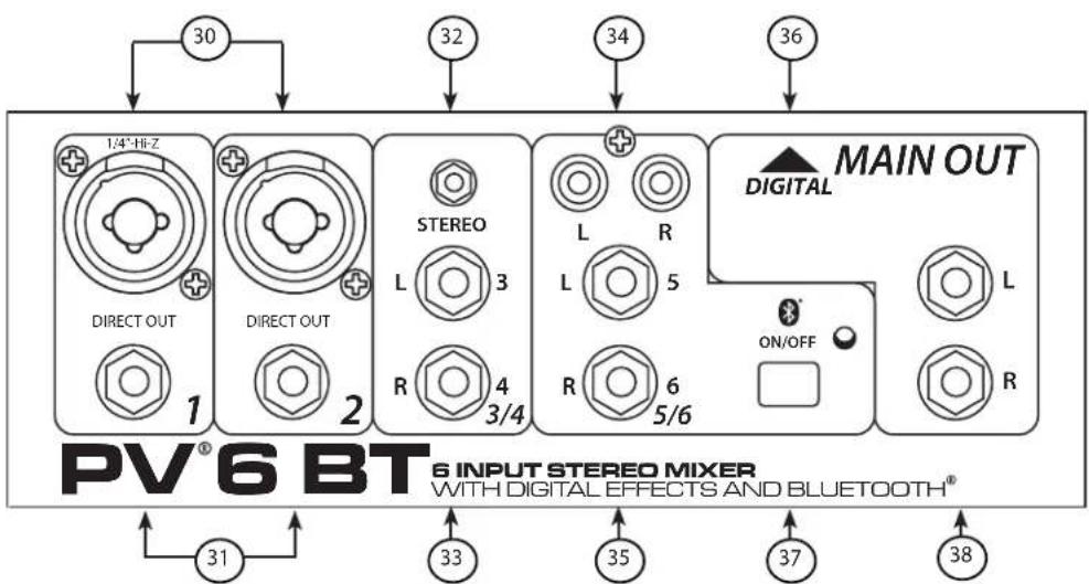
This combination input jack can accept either a 1/4" (balanced or unbalanced) input or a XLR balanced, low-impedance connection. The tip is positive on the 1/4" balanced input, and pin 2 is positive on the XLR. When ELECTRIC GUITAR PRE-SHAPE is depressed, the channel 1 1/4" input changes to a high impedance (1 MegΩ), like a 12AX7 vacuum tube guitar amplifier input.
31 1/4" TRS Direct Outs
Impedance-balanced outputs fed by the mic preamp. Channel 1 output is after the ELECTRIC GUITAR PRE-SHAPE switch.
32 Stereo 3.5mm Input
Accept a stereo input from the output of an MP3 player, CD player, tape deck or other similar device. This input is optimized for portable handheld devices and therefore has very high sensitivity.
33 Stereo Inputs
Channels 3 and 4 feature stereo inputs via 1/4" jack. If only one jack is used, it behaves as a mono source with a pan control. Once both jacks are connected, it behaves as a stereo source with a balance control; 3 is Left and 4 is Right.
③4 RCA Connection
Accept a stereo input from the output of an MP3 player, CD player, tape deck or other similar device. This input is optimized for portable handheld devices and therefore has very high sensitivity.
(35) Stereo
Accept a stereo input from the output of an MP3 player, CD player, tape deck or other similar device. This input is optimized for portable handheld devices and therefore has very high sensitivity.
36 Main Out
Ground compensated TRS balanced outputs fed by the master LEVEL control (28). These outputs can be used with Tip Ring Sleeve (TRS) balanced or Tip Sleeve (TS) unbalanced connectors.
37 Bluetooth® Activation Button
Press and hold this button until the LED blinks 3 times, indicating the Bluetooth has been powered on or off, then release. Once turned on, the Bluetooth will automatically enter pairing mode. You can pair any Bluetooth-enabled device with the mixer using the PIN 7878. To clear the paired device memory, make sure the Bluetooth is turned off and press and hold the button for at least 10 seconds. The LED will initially blink 3 times but then should remain off. Once you have released the button after 10 seconds, you can proceed by powering it on as normal, and the memory will be cleared.
38 Left/Right Outputs
The Left/Right Outputs feature two 1/4" TRS Z-balanced jacks. These outputs can be used with Tip Ring Sleeve (TRS) balanced or Tip Sleeve (TS) unbalanced connectors.

DC POWER INLET

Use to connect the included power supply. Be sure the power supply is connected to the PV*10 before connecting to a power source. Use 15VDC, 1A adapter only. Replace only with Peavey part number 30908119.
POWER SWITCH
This is the main power switch.
USB PORT TYPE B
The USB port is used to connect the PV ^® Series USB mixer to a computer for recording or playing back digital audio to/from your computer. The USB port sends the mixer's main/tape stereo out to the computer. The USB port receives digital audio from the computer; it can then be assigned through the USB TO Main switch ( 18 , PV6; 21 , PV6BT) to the main left/right output, if the computer is being used for playback only. For recording, use the USB TO CONTROL ROOM control ( 17 , PV6; 20 , PV6BT), to avoid creating a loop. Compatible with Windows ^® Vista, Windows 7, & Windows 8, Mac OS X ^® 10.0 or later, and iOS devices.
PV®6BT EFX
1 - Plate Reverb Bright
2 - Plate Reverb Medium Low-Pass
3 - Plate Reverb Dark
4 - Hall Reverb Vocal
5 - Hall Reverb Vocal Huge
6 - Hall Reverb Strings
7 - Room Reverb Vocal Air
8 - Room Reverb Snare Low
9 - Room Reverb Acoustic Guitar
10 - Delay Double
11 - Delay Slapback
12 - Delay Bright, Few Repeats
13 - Delay Bright, More Repeats
14 - Chorus High Depth, Slow Rate
15 - Chorus Moderate Depth, Wide Rate
16 - Chorus Short Depth, Fast Rate
Block Diagram

flowchart
graph TD
    subgraph CHANNEL 1
        A["LINE"] --> B["Gain"]
        B --> C["EQ"]
        C --> D["Signal"]
        D --> E["CLIP"]
        E --> F["Master"]
        F --> G["Compressor"]
        G --> H["Enable"]
        H --> I["Threshold"]
        I --> J["Output Level Meters"]
        J --> K["LEFT OUT"]
        J --> L["To USB B Streaming Output"]
        J --> M["RIGHT OUT"]
    end

    subgraph CHANNEL 2
        N["LINE"] --> O["Gain"]
        O --> P["EQ"]
        P --> Q["Signal"]
        Q --> R["CLIP"]
        R --> S["Master"]
        S --> T["Compressor"]
        T --> U["Enable"]
        U --> V["Threshold"]
        V --> W["Monitor Bus"]
        W --> X["Headphone"]
        X --> Y["A8 Toolo"]
        Y --> Z["Control Rm A"]
        Y --> AA["Control Rm B"]
    end

    subgraph CHANNEL 3/4
        AB["3.5nm"] --> AC["Input Selector"]
        AC --> AD["EQ"]
        AD --> AE["Signal"]
        AE --> AF["CLIP"]
        AF --> AG["Master"]
        AG --> AH["PVB ONLY"]
        AH --> AI["EFX SEND"]
        AI --> AJ["PVB ONLY"]
        AJ --> AK["EFFECTS"]
        AK --> AL["EFX Out"]
        AL --> AM["EXE SELECT"]
        AM --> AN["MUTE"]
    end

    subgraph CHANNEL 5/6
        AO["BUETOOT INPUT (dT Rate Only)"] --> AP["STATUS"]
        AP --> AQ["Digital Return Level"]
        AQ --> AR["To Monitor Bus"]
        AR --> AS["USB B Streaming Return"]
    end

    %% Note: The diagram shows multiple interconnected nodes representing different channels and their interconnections.
PV®6 & PV®6BT Series Specifications
Mic pre EIN = -126 dBu @ max gain with 150 ohm source
Inputs
| Function Input Z Input | Gain Setting M | Input Levels | Bal/ Unbal | Connector | |||
| n** Nominal | * Max | ||||||
| Microphone (150 ohms) | 2 kΩ Max Gain | (59 dB) | -71 dBu | -51 dBu | -39 dBu | Bal XLR Pin 1 GndPin 2 (+)Pin 3 (-) | |
| Min Gain (4 dB) | -17 dBu | +5 dBu | +16 dBu | ||||
| Line (10 k ohms) | 10 kΩ | Max Gain (40 dB) | -52 dBu | -32 dBu | -20 dBu | Bal 1/4" TR$;Tip (+)Ring (-)Sleeve Ground | |
| Line 1, GTR SHAPE ON | 1 Meg Ω @ ≤ 200 Hz, like 12AX7 input. | Min Gain (-15 dB) | +2 dBu | +23 dBu | > +32 dBu | ||
| Line 3/4 | 10 kΩ | Max Gain (19 dB) | -32 dBu | -12 dBu | +2 dBu | Unbal 1/4" TS;Tip (+)Sleeve Ground | |
| Nominal | -15 dBu | +6 dBu | +13 dBu | ||||
| 3.5mm | 2.8 kΩ | Max Gain (30 dB) | -44 dBu | -24 dBu | -10 dBu | 3.5mm; Tip=L, Ring=R,Sleeve Ground | |
| Nominal | -27 dBu | -6 dBu | +8 dBu | ||||
| Line 5/6 | 6.8 kΩ | Max Gain (18 dB) | -43 dBu | -23 dBV | -10 dBu | Unbal | 1/4" TS; Tip (+), Sleeve Ground |
| Nominal | -13dBu | -3 dBu | +12dBu | ||||
| RCA | 2.2 kΩ | Max Gain (29 dB) | -32 dBu | -22 dBu | -8 dBu | RCA: Tip (+),Sleeve Ground | |
| Nominal | -19 dBu | -8 dBu | +6dBu | ||||
0 dBu=0.775 V (RMS)
** Min Input Level (sensitivity) is the smallest signal that will produce nominal output (+4 dBu) with channel and master faders set for maximum gain.
* Nominal settings are defined as all controls set at 0 dB (or 50% rotation for rotary pots) except the gain adjustment pot which is as specified.
Outputs
| Function Min LoadZ(ohms) | Output LevelsNominal Max | Bal/Unbal | Connector | |
| Main Left/Right 600 +4 dBu +20 dBu Bal | XLR Pin Ground Tip | Pin 2 (+), Pin 3 (-)1/4" TRS: Tip (+), Ring (-)Sleeve Ground | ||
| Effects Send (PV6 only) | 600 +4 dBu +20 dBu Bal | 1/4" TRS: Tip (+), Ring (-)Sleeve Ground | ||
| Control Room | 600 | +4 dBu | +20 dBu | Unbal |
| Headphone | 8 | +4 dBu (no load) | +20 dBu | Unbal |
0 dBu=0.775 V (RMS)
Gain
| Mic Input Gain Adjustment Range: +4 dB to +59 dB | |
| Mic Input to Left/Right Balance Output 79 dB (max gain) | |
| Line Input Gain Adjustment Range: -15 dB to 40 dB | |
| Line Input to Left/Right Balance Output 60 dB (max gain) | |
| Stereo 3/4 Gain Adjustment Range: Off to +19 dB | |
| Stereo3/4 to Left/Right Output 39 dB (max gain) | |
| 3.5mm Input Gain Adjustment Range: Off to +30 dB | |
| 3.5mm Input to Left/Right Output 51 dB (max gain) | |
| Stereo Line 5/6 Gain Adjustment Range: Off to +18 dB | |
| Stereo 5/6 to Left/Right Output 28 dB (max gain) | |
| RCA Gain Adjustment Range: | Off to +29 dB |
| RCA to Left/Right Output | 39 dB (max gain) |
Frequency Response
Mic Input to Left/Right Output 10 Hz to 20 kHz +0 dB/-1 dB
Total Harmonic Distortion
<0.006% Typical (22 Hz to 22 kHz BW)
Hum and Noise
| Output | Residual Noise | S/N Ratio (Ref: +4dBu) | Test Conditions |
| Master Left/Right | -97 dBu | 101 dB | Master Fader Down, Channel Levels Down |
| -92 dBu | 96 dB | Master Fader Nominal, Channel Levels Down,Efx muted | |
| -82 dBu | 86 dB | Master Fade Nominal, Channel Faders Nominal,Panned Odd Channels (left), Even Channels(right) |
(Hum and noise measurements: 22 Hz to 22 kHz BW)
Equivalent Input Noise (EIN)
-126 dBu (input terminated with 150 ohms, bandwidth 20 kHz)
Crosstalk/Attenuation
Adjacent Input Channels (1 kHz) >90 dB
Left to Right Outputs (1 kHz) >70 dB
Channel level control Kill (1 kHz) >85 dB
Common Mode Rejection Ratio (Mic Input)
50 dB minimum (20 Hz to 20 kHz)
70 dB typical @ 1 kHz
Meters
Signal/Overload Indicators
6 segment, peak reading (top green LED = +4 dBu)
Red LED lights 5 dB below clipping
Dimensions
7.25" wide x 11.4" deep x 2.1875" high
(18.42 cm × 28.96 cm × 5.56 cm)
Weight
Power Requirements
PV6: 3.99 lbs (1.81 kg)
100-240 VAC 50/60 Hz 15 Watts
PV6BT: 4.06 lbs (1.84 kg)

Installation Note:
"This unit must have the following clearances from any combustible surface: top: 8", sides: 12", back: 12"
PEAVEY ELECTRONICS CORPORATION LIMITED WARRANTY
Effective Date: 11/01/2011
What This Warranty Covers
Your Peavey Warranty covers defects in material and workmanship in Peavey products purchased and serviced in the U.S.A. and Canada.
What This Warranty Does Not Cover
The Warranty does not cover: (1) damage caused by accident, misuse, abuse, improper installation or operation, rental, product modification or neglect; (2) damage occurring during shipment; (3) damage caused by repair or service performed by persons not authorized by Peavey; (4) products on which the serial number has been altered, defaced or removed; (5) products not purchased from an Authorized Peavey Dealer.
Who This Warranty Protects
This Warranty protects only the original purchaser of the product.
How Long This Warranty Lasts
The Warranty begins on the date of purchase by the original retail purchaser. The duration of the Warranty is as follows:
| Product Category Duration | |
| Guitars/Basses, Amplifiers, Preamplifiers, Mixers, Electronic Crossovers and Equalizers 2 years *(+ 3 years) | |
| Drums 2 years *(+ 1 year) | |
| Enclosures 3 years *(+ 2 years) | |
| Digital Effect Devices and Keyboards and MIDI Controllers 1 years *(+ 1 year) | |
| Microphones 2 years | |
| Speaker Components(incl. Speakers, Baskets, Drivers, Diaphragm Replacement Kits and Passive Crossovers) | 1 year |
| Tubes and Meters | 90 Days |
| Cables Limited Lifetime | |
| AmpKit Link, Xport, Rockmaster Series, Strum'n Fun, RetroFire, GT & BT Series Amps | 1 year |
| Marvel Jr. Guitar | 90 Days |
[* Denotes additional Warranty period applicable if optional Warranty Registration Card is completed and returned to Peavey by original retail purchaser within 90 days of purchase.]
What Peavey Will Do
We will repair or replace (at Peavey's discretion) products covered by Warranty at no charge for labor or materials. If the product or component must be shipped to Peavey for Warranty service, the consumer must pay initial shipping charges. If the repairs are covered by Warranty, Peavey will pay the return shipping charges.
How To Get Warranty Service
(1) Take the defective item and your sales receipt or other proof of date of purchase to your Authorized Peavey Dealer or Authorized Peavey Service Center.
OR
(2) Ship the defective item, prepaid, to Peavey Electronics Corporation, International Service Center, 412 Highway 11 & 80 East, Meridian, MS 39301. Include a detailed description of the problem, together with a copy of your sales receipt or other proof of date of purchase as evidence of Warranty coverage. Also provide a complete return address.
Limitation of Implied Warranties
ANY IMPLIED WARRANTIES, INCLUDING WARRANTIES OF MERCHANTABILITY AND FITNESS FOR A PARTICULAR PURPOSE, ARE LIMITED IN DURATION TO THE LENGTH OF THIS WARRANTY.
Some states do not allow limitations on how long an implied Warranty lasts, so the above limitation may not apply to you.
Exclusions of Damages
PEAVEY'S LIABILITY FOR ANY DEFECTIVE PRODUCT IS LIMITED TO THE REPAIR OR REPLACEMENT OF THE PRODUCT, AT PEAVEY'S OPTION. IF WE ELECT TO REPLACE THE PRODUCT, THE REPLACEMENT MAY BE A RECONDITIONED UNIT. PEAVEY SHALL NOT BE LIABLE FOR DAMAGES BASED ON INCONVENIENCE, LOSS OF USE, LOST PROFITS, LOST SAVINGS, DAMAGE TO ANY OTHER EQUIPMENT OR OTHER ITEMS AT THE SITE OF USE, OR ANY OTHER DAMAGES WHETHER INCIDENTAL, CONSEQUENTIAL OR OTHERWISE, EVEN IF PEAVEY HAS BEEN ADVISED OF THE POSSIBILITY OF SUCH DAMAGES.
Some states do not allow the exclusion or limitation of incidental or consequential damages, so the above limitation may not apply to you.
This Warranty gives you specific legal rights, and you may also have other rights which vary from state to state.
If you have any questions about this Warranty or services received or if you need assistance in locating an Authorized Service Center, please contact the Peavey International Service Center at (601) 483-5365.
Features and specifications are subject to change without notice.
Meridian, Ms 39305
PO Box 1150
Attn: Warranty Department
Corporation
Peaey Electronics

natural_image
Abstract black-and-white geometric logo design with stylized arrow-like shapes (no text or symbols)Here
Postage
Place


- PV ® 6·PV ® 6BT
- Compact Mixer
- FC
- FCC/ICES Compliancy Statement
- Caution
- FEATURES (both models):
- PV6BT ADDITIONAL FEATURES:
- PV6 ONLY:
- Electric Guitar Pre-Shape
- Signal Presence/Clip LED
- Gain
- High EQ
- Mid EQ
- Low EQ
- EQ Bypass
- EFX Send
- Pan
- Channel Level
- PV®6 Front Panel
- EFX Level
- Headphone Level
- Compressor Control
- Level
- Headphone Output
- PV®6BT Front Panel
- RCA Connectors for Monitor
- A/B Toggle Switch
- Monitor Level
- Phantom Power
- Headphone Level
- Compressor Control
- Level
- Headphone Output
- MIC/LINE INPUT
- 1/4" TRS Direct Outs
- Stereo 3.5mm Input
- Stereo Inputs
- RCA Connection
- Stereo
- EFX Send
- Main Out
- MIC/LINE INPUT
- 1/4" TRS Direct Outs
- Stereo 3.5mm Input
- Stereo Inputs
- ③4 RCA Connection
- Stereo
- Main Out
- Bluetooth® Activation Button
- Left/Right Outputs
- DC POWER INLET
- POWER SWITCH
- USB PORT TYPE B
- PV®6BT EFX
- PV®6 & PV®6BT Series Specifications
- Frequency Response
- Total Harmonic Distortion
- Equivalent Input Noise (EIN)
- Crosstalk/Attenuation
- Common Mode Rejection Ratio (Mic Input)
- Meters
- Dimensions
- Weight
- PEAVEY ELECTRONICS CORPORATION LIMITED WARRANTY
Brand : PEAVEY
Model : PV 6
Category : Blender