
XR-AT - Blender PEAVEY - Free user manual and instructions
Find the device manual for free XR-AT PEAVEY in PDF.


| Product Type | Powered Mixer |
| Brand | Peavey |
| Model | XR-AT |
| Dimensions (H x W x D) | 11.25" x 19.375" x 10.75" (285.75 mm x 492.12 mm x 273.05 mm) |
| Weight | 22.2 lbs (10.07 kg) |
| Power Requirements | Domestic: 120 VAC 50/60 Hz, Export: 230 VAC 50/60 Hz, 200 W Nominal |
| Amplifier Output Power | 280 W RMS per channel at 8 ohms, 500 W RMS per channel at 4 ohms |
| Inputs | 8 combo XLR/1/4" (channels 1-8), RCA and 3.5 mm media (channel 8), USB-A (channel 9), Bluetooth |
| Outputs | Main out (TRS balanced), Monitor out (TRS balanced), Sub/Mono out (TRS balanced), RCA record out, Speaker outputs (1/4"-Speakon combo) |
| Equalization | Dual 9-band graphic EQ with FLS; channel EQ: Low (80 Hz ±15 dB), Mid-Morph (250 Hz/4 kHz ±15 dB), High (12 kHz ±15 dB); Mid EQ on channels 8-9 (450 Hz ±15 dB) |
| Built-in Effects | 24-bit digital effects: Plate, Hall, Room, Delay, Enhance, Chorus (multiple presets) |
| Auto-Tune | 3 channels of Antares Auto-Tune with pitch correction, key and speed settings, 9 presets |
| Special Features | FLS Feedback Locating System, Midmorph EQ, Kosmos-C bass enhancement, DDT speaker protection, global 48V phantom power, master mic mute, footswitchable effects defeat, USB playback, Bluetooth streaming |
| Phantom Power | +48 VDC, global switch, applies to all XLR inputs |
| Power Amplifier Configuration | Selectable: both amps for main, or amp 1 for main and amp 2 for monitor |
| Speaker Impedance | Minimum 4 ohms per amplifier |
| Safety and Compliance | FCC Part 15 Class B, CE marked, voltage selector, fuse protection |
| Accessories Included | IEC power cord; optional footswitch (Peavey part# 03014070) |
| Care and Cleaning | Wipe with dry cloth; avoid liquids and solvents |
| Reparability | Refer to authorized Peavey service center for repairs; do not open unit |
| Warranty | Register at www.peavey.com/warranty |
| General Information | Manufacturer: Peavey Electronics Corporation, Meridian, MS, USA |
Frequently Asked Questions - XR-AT PEAVEY
User questions about XR-AT PEAVEY
0 question about this device. Answer the ones you know or ask your own.
Ask a new question about this device
Download the instructions for your Blender in PDF format for free! Find your manual XR-AT - PEAVEY and take your electronic device back in hand. On this page are published all the documents necessary for the use of your device. XR-AT by PEAVEY.
USER MANUAL XR-AT PEAVEY
XR® AT
Powered Mixer
Operating
Manual

FC
This device complies with Part 15 of the FCC rules and Industry Canada license-exempt RSS Standard(s). Operation is subject to the following two conditions: (1) this device may not cause harmful interference, and (2) this device must accept any interference received, that may cause undesired operation.
Warning: Changes or modifications to the equipment not approved by Peavey Electronics Corp. can void the user's authority to use the equipment.
Note – This equipment has been tested and found to comply with the limits for a Class B digital device, pursuant to Part 15 of the FCC Rules. These limits are designed to provide reasonable protection against harmful interference in a residential installation. This equipment generates, uses, and can radiate radio frequency energy and, if not installed and used in accordance with the instructions, may cause harmful interference to radio communications. However, there is no guarantee that interference will not occur in a particular installation. If this equipment does cause harmful interference to radio or television reception, which can be determined by turning the equipment off and on, the user is encouraged to try and correct the interference by one or more of the following measures.
• Reorient or relocate the receiving antenna.
- Increase the separation between the equipment and receiver.
- Connect the equipment into an outlet on a circuit different from that to which the receiver is connected.
- Consult the dealer or an experienced radio/TV technician for help.
Caution
The equipment complies with FCC radiation exposure limits set forth for an uncontrolled environment.

ENGLISH
XR ® -AT
Powered Mixer
Congratulations on the purchase of your new XR®-AT powered mixer from Peavey®. The Peavey XR-AT is a revolutionary all in one powered mixer. Everything a musician or DJ needs providing up to eight combination XLR and 1/4" inputs using Peavey's award winning mic preamps and dual 500 Watt amplifiers for crystal clear audio reproduction. The Peavey XR-AT uses exclusive features like Midmorph® to accurately improve tone and clarity of vocals. Feedback is quickly and easily identified and removed with Peavey's dual 9-band graphic EQ's combined with our patented and revolutionary FLS® Feedback Locating System. The XR-AT is equipped with Peavey's exclusive Kosmos®-C technology, which drastically enhances the low end of the audio spectrum. Built-in 24-bit digital effects compliment the already feature packed unit.

Before you begin using your powered mixer it is very important to ensure that the product has the proper AC voltage supplied. You can find the proper voltage for your amp printed next to the IEC line (power) cord on the rear panel of the unit.
Features:
• FLS ® Feedback Locating System
- Midmorph® EQ
- Kosmos irc -C
- On-board 24-bit Digital Effects With Mute Button
• Digital Effects Parameter Control
• Combination XLR and 1/4" input jacks
• Dual 9-band Graphic EQ with FLS
- Master Mic Mute
• Footswitchable Effects Defeat
• Global 48 Volt Phantom Power
• RCA, 3.5mm Media Inputs
- Bluetooth® Streaming
• USB Audio Playback
- Selectable Main or Monitor Dual Power Amp
- RCA Record Outputs
• LED Meter Bridge
• Power Amp Sub-sonic Filter
- Clip and Signal Present Indicators
- Main and Monitor 1/4" Line Level Outputs
- DDT™ Speaker Protection Circuit
- Three Channels of Antares® Auto-tune™ Pitch Correction

Channel Controls

① MIC/LINE INPUT (CH.1-8)
This combination input jack can accept either a 1/4" (balanced or unbalanced) input or a XLR balanced, low-impedance connection. The tip is positive on the 1/4" balanced input, and pin 2 is positive on the XLR
PAD (CH. 1-7)
When engaged, the pad reduces the input signal by 25dB. If you notice distortion from a particular channel or if the channel becomes loud very quickly, try engaging this switch. In addition to increasing the dynamic range, the channel can now accommodate a higher input level before clipping occurs, which may be helpful when close-mic'ing a loud guitar amp or drum kit, for example.
MEDIA INPUTS (CH.8 RCA and 3.5mm)
These inputs, both RCA and 3.5mm jacks accept a stereo input from the output of an MP3 Player, CD player, tape deck or other similar device.
④ INPUT SELECT SWITCH (CH. 8)
This switch allows the user to select the input signal being sent to channel 8. In the "up" position, the Mic-Line preamp is active. In the "down" position, the RCA-3.5mm media inputs are active.
⑤ AUTO-TUNE ON/OFF (CH 1-3)
Each of the first three channels of the XR-AT can be routed through the world famous Auto-tune processing for automatic pitch correction. These three backlit switches indicate the status of the Auto-tune in each channel. They also allow the Auto-tune process to be bypassed with the push of a button. When the switch is lit, Auto-tune is active. When it is dark, the Auto-tune process is bypassed.
6 COMPRESSOR AND COMP LED (CH 1-7)
This knob adjusts the amount of compression applied to the channel. As the knob is turned to the right, the mixer automatically raises the compression ratio while adjusting the output gain accordingly. The result is a
narrower, more even dynamic range, as louder signals are softened while the overall level is boosted. Avoid setting the knob too high, however, as excess compression may lead to feedback. The LED will light red when the signal level is high enough to activate the compression.
HIGH EQ
This High EQ shelving type of active tone control varies the treble frequencies (+/- 15 dB at 12kHz) and is designed to remove noise or add brilliance to the signal, depending on the quality of the source.
MID-MORPH EQ (CH. 1-7)
Where most mid-range controls work at just one frequency, the Mid-Morph works at two. When turned counterclockwise, it cuts at 250Hz to reduce frequencies that muddy the sound. When turned clockwise, it boosts at 4kHz to add intelligibility to vocals. Either way, improved vocal or instrument definition can be achieved.

9
MID EQ (CH. 8 & 9)
The mid EQ is a band-pass (peak/notch) type of active tone control that varies the mid-range frequencies (+/-15dB at 450Hz).
10
LOW EQ
A shelving type of EQ that varies the bass frequency levels (+/- 15dB at 80Hz). Low EQ adds depth to thin-sounding signals or cleans up the muddy ones. As with any EQ, use sparingly. Too much of this EQ can give you a booming bottom end.
||
MONITOR SEND
The monitor send adjusts the level of the channel signal added to the monitor mix.
12
AUTO-TUNE TO MONITOR BUTTON (CH. 1-3)
This allows the user to select whether to send the dry signal or the auto-tuned signal to the monitors in the Auto-tune capable channels.
13
EFFECTS SEND (CH. 1-8)
This control adjusts the level of the channel signal added to the effects mix. The signal is sent to the internal effects processor. Turning the knob to the left (0) will turn off the effects on the associated channel, while turning the knob to the right will increase the amount of the selected effect.
14
LEVEL
This control sets the signal level sent to the main mix.
15
CLIP
When this LED turns on or blinks red, it is an indication that the signal in the channel is potentially too strong and could cause distortion. Turn down the Level control (12) until the Clip light is no longer present. If you are having difficulty getting a clean signal, try varying the output of the connected device, if possible.
16
SIG
When this LED is green, it is an indication the mixer is receiving signal at the input of the channel. If you are having trouble getting sound out of the mixer and this LED is not on, check the microphone, instrument or cable that is connected to the channel.
17
USB MEDIA JACK (CH. 9)
A-type USB connector that a removable data storage device can be connected to playback music
USB PLAYBACK:
First, make sure channel 9 is in USB playback mode by checking the status of the Ch 9 INPUT button (37). When the switch is dark, channel 9 is in USB playback mode. If it is blinking or solid blue, it is in Bluetooth mode. The bottom of the LCD display will say "Insert USB Drive" when in USB playback mode.
Insert your USB drive in the USB Media Jack (17) at the top of channel 9. The mixer will now go into folder navigation mode.
In folder navigation mode, you can navigate through all of the folders present in the USB drive. The first folder in the list will always be "
In song navigation mode, you can select a song by turning and pressing the "Media Select" encoder or by pressing the "Next" and "Previous" switches. If you were currently playing a song and selected a new song, the mixer will automatically start playing the new song. If you were paused or stopped, the mixer will select the new song and remain stopped. To fast forward a song, press and hold the "Next" switch, and to rewind a song, press and hold the "Previous" switch.
To go back to folder navigation mode, scroll all the way to the left and there will be an option called "
If a folder is selected that has no playable songs, "No Songs" will be displayed on the LCD. Scroll to the left and select "

MASTER CONTROLS FLS
When feedback occurs, the corresponding LED of the frequency that is closest to the frequency that is feeding back will illuminate over the slider to be adjusted. Slowly bring the corresponding slider down until feedback is gone. The LED will remain illuminated for a few seconds after the feedback is gone. If the feedback doesn't return, all of the LEDs will become active again, acting as a normal EQ.
GRAPHIC EQ
These nine-band Equalizers are designed to either be used to reduce feedback or to adjust the overall frequency response of the signal being sent to the amplifiers. Subtle adjustments made with the graphic equalizer can improve the way your loudspeaker system sounds in the room. You should be aware however, that setting large amounts of boost or arbitrary curves can reduce amplifier headroom, leading to
early distortion or just plain bad or unintelligible sound. Working with the FLS, the graphic EQ can also be used to reduce feedback. Each band of EQ can supply up to 12dB of boost or cut.
LEVEL LED LADDER
These LEDs indicate the signal level of the main mix and the monitor mix. The top LED indicates LIMIT and activation of our revolutionary DDT speaker protection circuit. Peavey's award winning speaker protection is built into the XR-AT powered mixer and is activated automatically to maximize the power amplifier without fear of distortion.
MAIN LEVEL
The Main level control sets the level of the main mix and the overall volume of the powered mixer.

MONITOR LEVEL
The Monitor level control adjusts the level of the signal coming out of the Monitor send 1/4" jack. It can also be assigned to feed the 2nd power amplifier via the selector switch (24).

EFX TO MON
This switch toggles the EFX return signal being sent to the monitors. When it is lit, the effects signal is being sent to the monitors.

POWER AMP 2 ASSIGN
This switch allows the user to select the signal that is assigned to power amp 2 (49). The user can either elect to send the Main mix signal or the Monitor mix signal to the second internal power amplifier. This allows the user to run both power amps for mains or use power amp 1 for mains and power amp 2 for monitors.

KOSMOS-C
The Kosmos-C uses special circuitry to enrich the sound of your system. This is not just a simple bass boost. It provides "natural bass enhancement" by adding harmonically related bass signals that track the envelope of the original signal. The Kosmos-C high control can be used to add clarity to dull signals.

KOSMOS ENABLE
When lit, the KOSMOS enhanced signal is added to the main mix. This allows you to compare the enhanced signal with the dry with the press of a button.

MIC MUTE
Depressing this button mutes the mic/line inputs in all 8 channels. The media input jacks (RCA and 3.5mm) on channel 8 and the USB/BT inputs on channel 9 are still "live". This allows you to play break music, while muting all of the microphone inputs.


EFX DEFEAT
This button mutes the effects being sent to the main mix, allowing the user to listen to a dry signal at the main outputs. When muted, the switch will be red. This can also be activated with a momentary footswitch. See (50).

EFX CLIP
This LED blinks red when the signal being sent to the effects section is too high and is causing distortion. Find the source of the hot signal by reducing the EFX send (13) on each channel until the LED is no longer lighting (blinking red).

LCD DISPLAY
The top row of this LCD displays the currently selected EFX preset or Autotune preset and the bottom row displays the status of the media inputs of channel 9. If channel 9 is in USB Playback Mode, it can also be used for navigating the folders on the USB drive or displaying the current song playing.
REW/PREV

A short press will rewind to the beginning of the current song. Pressing this button twice will take you to the previous song on the USB drive. A long press will rewind through the current song, release to play when you reach the desired spot in the song.

PLAY/PAUSE
The play/pause button toggles the current song between play and pause. When the > is displayed, the song will be playing. When II is displayed, the song is paused. When [] is displayed, the song is stopped.

FF/NEXT
A short press will advance the media player to the next song on the USB drive. A long press will fast forward through the current song, release to play when you reach the desired spot in the song.
EFX SELECT/AUTO-TUNE ADJUST
The EFX Select/Auto-tune Adjust knob is a dual function control. It can be used to navigate and select the desired DSP effect. In the Auto-tune edit mode, it can be used to select presets and navigate the Auto-tune edit functions.
Please see the "Operating the DSP" section for further information.
EDIT AUTO-TUNE
The Edit Autotune switch is used to enter Autotune editing mode. When it is engaged (lit), the current Autotune preset will be displayed on the LCD. When it is disengaged (dark), the current EFX preset will be displayed on the LCD.
MEDIA SELECT
This encoder is used to control USB playback navigation. For more information on this, see "USB Playback".
CH 9 INPUT SELECT (USB/BLUETOOTH)
This switch allows the user to select the input signal being sent to channel 9. It can select between the USB A connector or a wireless Bluetooth connection from an external device (Smartphone, iPod, or tablet).
BLUETOOTH ACTIVE LED
The CH 9 INPUT button will also function as the Bluetooth Status LED. The blue backlit switch will indicate the status of the Bluetooth connection. If the LED is off, the Bluetooth module is powered off and channel 9 is in USB Playback Mode. If the LED is slowly flashing, the XR-AT is not paired with any device, but is available for connection. When the LED is lit solid, the source device is properly paired to the mixer and ready to play.

EFX Mode
In EFX Edit Mode (see Auto-Tune Switch), the EFX Select knob is used to navigate through the EFX presets. Turning the knob changes the EFX preset in the display. The new selection will be blinking in the display; push the EFX Select knob to choose the new effect. Once the effect has been selected, you can now edit the effect. To do this, press the EFX Select knob and the display will change to the current parameter setting of the preset. Turn the EFX Select knob to edit the parameter. Press the knob again to exit EFX preset edit mode. To restore the EFX presets back to factory settings, press and hold the EFX Select knob for 5 seconds and select "Y" when prompted.
Auto-Tune Mode:
In Auto-Tune Edit Mode (see Auto-Tune Switch), the EFX Select knob is used to navigate through the Auto-Tune presets. Turning the knob changes the Auto-Tune preset in the display. The new selection will be blinking in the display; push the EFX Select knob to choose the new Auto-Tune preset.
Once the preset has been selected, you can edit the preset by pressing the EFX Select knob. The display will change to the current Key setting. Turn the EFX Select knob to change the key and push the EFX Select knob when you have chosen the key you desire. The Key setting determines which notes are enabled in the Auto-Tune process. For example, in the key of CMaj, the notes C, D, E, F, G, A, and B are enabled, and all other notes are disabled. To see which notes are enabled or disabled for each key, see the Key Table.
Note:
If Custom Key is selected, the display will enter Custom Key Edit Mode. In this mode, you can create a custom Auto-Tune Key. Use the EFX Select knob to select the Root (labeled "RT"). This will be the note off which the custom key is based. Then use the Media Select knob to move the cursor and use the EFX Select knob to activate or deactivate the 12 notes in the key. Once you have finished editing the custom key, press the EFX Select knob to exit Custom Key Edit Mode. The mixer is capable of storing 9 different custom keys, one for each preset slot.
The scale degrees are numbered across the top, with half-steps indicated by a dash.
NOTE: If Custom Key is selected, the display will enter Custom Key Edit Mode. In this mode, you can create a custom Auto-Tune Key. Use the EFX Select knob to select the Root (labeled "RT"). This will be the note off which the custom key is based. Then use the Media Select knob to move the cursor and use the EFX Select knob to activate or deactivate the 12 notes in the key. Once you have finished editing the custom key, press the EFX Select knob to exit Custom Key Edit Mode. The mixer is capable of storing 9 different custom keys, one for each preset slot.
The scale degrees are numbered across the top, with half-steps indicated by a dash.

"+" indicates the note will be allowed. "-" indicates the note will not be allowed.
By looking at the sequence of allowed and disallowed notes above, this is a whole tone scale. There are only two of those, so you can have the other one just by changing the root to C# or B.

*This screen cap shows an A blues scale. You don't have to edit the whole scale to change keys - just change the root.
Once you have selected the key and pressed the EFX Select knob, the display will change to the current Speed setting. Turn the EFX Select knob to change the Speed setting. The Speed setting determines how quickly and aggressively the Auto-Tune will correct the pitch. The range for this setting is 0 to 25, where 0 is the quickest and 25 is the slowest. Push the EFX Select knob when you are done editing the speed parameter.
The display will now change to the current Detune setting. Turn the EFX Select knob to change the Detune setting. The Detune setting determines how the Auto-Tune pitch correction is calibrated. When the Detune setting is 0 cents, this means the Auto-Tune is calibrated to the standard A440, or where the note A4 equals 440 Hz. The range of the Detune setting is -64 to 63 cents, a width of 128 cents. The distance between two notes, or semitones, is 100 cents, which means that the Auto-Tune can be detuned to fit any possible environment.
NOTE: Detuning the Auto-Tune can be very useful, especially when being used in conjunction with an instrument that is not easily tuned on-the-fly. For example, if a piano is accompanying Auto-Tuned vocals and the piano is slightly out of tune from the A440 standard, simply change the Detune setting in the Auto-Tune setting. This is much easier and takes much less time than having some one tune the entire piano! Also, although the Detune setting is changed in the Auto-Tune preset edit mode, this is a global parameter. This means if you change the Detune setting and then later change the Auto-Tune preset, the Detune setting will not change.
Once you have selected the appropriate Detune setting, press the EFX Select knob to exit Auto-Tune preset edit mode. To restore all Auto-Tune presets back to factory settings, press and hold the EFX Select knob for 5 seconds and select "Y" when prompted.
NOTE: Preset 9 is chromatic with speed set to 7. It is recommended for general purpose, safe, easy use of Autotune, without having to adjust any settings. The slower speed setting does not produce a robotic effect on the voice, and all twelve semitones are allowed. Just remember to use footswitch #2 to bypass Autotune between songs, otherwise your speaking will be Autotuned!
Auto-Tune Key Table Key Display Note Number (n)=
| Key | 0 | 1 | 2 | 3 | 4 | 5 | 6 | 7 | 8 | 9 | ||
| Chrom | C C# | D D# | E F | F# G | G# | A A# | B | |||||
| C Maj | C | D | E | F | G | A | B | |||||
| C Mnr | C | D | D# | F | G | G# | A# | |||||
| C#Maj | C | C# | D# | F | F# | G# | A# | |||||
| C#Mnr | C# | D# | E | F# | G# | A | B | |||||
| D Maj | C# | D | E | F# | G | A | B | |||||
| D Mnr | C | D | E | F | G | A | A# | |||||
| D#Maj | C | D | D# | F | G | G# | A# | |||||
| D#Mnr | C# | D# | F | F# | G# | A# | B | |||||
| E Maj | C# | D# | E | F# | G# | A | B | |||||
| E Mnr | C | D | E | F# | G | A | B | |||||
| F Maj | C | D | E | F | G | A | A# | |||||
| F Mnr | C | C# | D# | F | G | G# | A# | |||||
| F#Maj | C# | D# | F | F# | G# | A# | B | |||||
| F#Mnr | C# | D | E | F# | G# | A | B | |||||
| G Maj | C | D | E | F# | G | A | B | |||||
| G Mnr | C | D | D# | F | G | A | A# | |||||
| G#Maj | C | C# | D# | F | G | G# | A# | |||||
| G#Mnr | C# | D# | E | F# | G# | A# | B | |||||
| A Maj | C# | D | E | F# | G# | A | B | |||||
| A Mnr | C | D | E | F | G | A | B | |||||
| A#Maj | C | D | D# | F | G | A | A# | |||||
| A#Mnr | C | C# | D# | F | F# | G# | A# | |||||
| B Maj | C# | D# | E | F# | G# | A# | ||||||
| B Mnr | C# | D | E | F# | G | A | B |
Bluetooth® Player
Bluetooth OPERATION
To listen to music via the Bluetooth wireless connection, you must first pair (link) your XR-AT mixer with your Bluetooth phone and/or music device.
Turn off any Bluetooth devices previously paired with the XR-AT mixer.
Turn on the Bluetooth feature on your phone or music device.
Make sure the XR-AT is ready for a Bluetooth connection.
The Bluetooth Active LED should be blinking and the LCD will say, "Bluetooth Input".
Place your phone or music device in Bluetooth search mode. The phone or music device will begin searching for the XR-AT.
Select "Peavey Mixer" from the search results on your phone or music device.
You will be prompted to enter a pin number. Enter the pin#, it is 7878 (or "PVPV" on a phone number pad).
If the pairing is successful, the Bluetooth Active LED will blink rapidly 5 times and then remain lit.
You are now ready to begin streaming through Bluetooth to the mixer. The level can be adjusted from the connected source or by the level control in Channel 9.
Inputs/Outputs


GLOBAL PHANTOM POWER
This switch, when depressed, applies +48 VDC to all input XLR connectors to power microphones that need phantom power to work.

This switch applies +48 VDC voltage to the input XLR connectors to power
microphones requiring phantom power. If phantom power is used, do not connect unbalanced dynamic microphones or other devices to the XLR inputs that cannot handle this Voltage.
RCA RECORD OUT
This pair of RCA jacks provides a signal to the recording inputs of a CD recorder, stereo tape deck or other recording device.
NOTE: Do not connect a single device to the Media Inputs (3) and Record Outputs. This improper
setup forms a loop, which can cause severe feedback.
MAIN OUT (TRS Balanced)
This 1/4" jack provides a signal from the main mix (after the graphic EQ) for an external power amplifier. An external power amplifier, such as our IPR series of amplifiers, can then drive additional speakers.
MONITOR OUT (TRS Balanced)
This 1/4" jack provides a signal from the monitor mix (x)(after the graphic EQ) for an external power amplifier. An external power amplifier, such as our IPR series of amplifiers, can then drive additional speakers.
SUB/MONO OUT (TRS Balanced)
This 1/4" jack provides a signal that passes all signals under 150Hz. This can be used to drive an external subwoofer amplifier or a powered
sub. The level of signal tracks the main output.
POWER AMP INPUTS
These are 1/4" inputs that allow an external line-level signal to be connected to each of the built-in power amps. Plugging an input into these jacks breaks the signal from the mixer to the built-in amplifier. The mixer output is still available at the Main out jack (40).


POWER SWITCH
This is the main power switch.
FUSE
This is the main safety fuse for the AC line voltage. Only replace with a fuse of the exact type and rating. If the fuse continues to open, do not over fuse. Take the unit to an authorized Peavey service center.
NOTE: If the main AC voltage is changed, the fuse must also be changed to one of the appropriate rating for the voltage you are switching to.

AC POWER INLET
This is the receptacle for an IEC line cord, which provide
AC power to the unit. Connect the line cord to this connector to provide power to the unit. Damage to the equipment may result if improper line voltage is used. (See line voltage marking on unit).
Never break off the ground pin on any equipment. It is provided for your safety. If the outlet used does not have a ground pin, a suitable grounding adapter should be used and the third wire should be grounded properly. To prevent risk of shock or fire hazard, always make sure that the amplifier and all associated equipment is properly grounded.

NOTE: FOR UK ONLY
As the colors of the wires in the mains lead of this
apparatus may not correspond directly with the colored markings identifying the terminals in your plug, proceed as follows: (1) The
green and yellow wire must be connected to the terminal which is marked with the letter E, or by the earth symbol, or is colored green, or green and yellow. (2) The blue wire must be connected to the terminal which is marked with the letter N, or the color black. (3) The brown wire must be connected to the terminal which is marked with the letter L, or the color red.

VOLTAGE SELECTOR SWITCH This switch allows the user to select between 115VAC /
60Hz or 230VAC / 50Hz. To change the voltage selector, you must first unscrew and remove the plastic cover that protects the switch.
After changing the voltage, please replace the plastic cover to ensure the voltage level is not inadvertently altered.
NOTE: The fuse MUST be changed to the appropriate value to match the voltage you have selected. Please see the note on the back of the mixer for the correct value.
Dual two-conductor 1/4" – Speakon* combination jacks that can be connected to your speakers. Each amplifier has a minimum load impedance of 4 ohms. This means you can connect either one 4-ohm, one 8-ohm or two 8-ohm speakers to each amplifier. Do not operate below rated minimum impedance. For maximum power transfer and to prevent damage to your amplifier, be sure to use speaker cables and not instrument cables to connect to the speakers. We recommend the use of 18-guage or larger speaker wire.

Dual two-conductor 1/4" – Speakon combination jacks that can be connected to your speakers. Each amplifier has a minimum load impedance of 4 ohms. This means you can connect either one 4-ohm, one 8-ohm or two 8-ohm speakers to each amplifier. Do not operate below rated minimum impedance. For maximum power transfer and to prevent damage to your amplifier, be sure to use speaker cables and not instrument cables to connect to the speakers. We recommend the use of 18-guage or larger speaker wire. The signal going to Power Amp 2 is determined by the position of the Power Amp 2 Assign switch (38). In the "MAIN" position, the main mix is fed to power amp 1 and power amp 2. In the "MON" position, the main mix is fed to power amp 1 and the monitor mix is fed to power amp 2.

FOOTSWITCH EFFECTS DEFEAT (TS)
This 1/4" jack accepts a momentary 1/4" momentary, dual - footswitch (Peavey Part# 03014070) designed to defeat the effects on all channels or toggle the Auto-tune on/off. Pressing switch 1 of the footswitch will toggle the effects on and of. The condition will be indicated by the EFX Defeat button o the front panel, when defeated, the button will be red. When the effects are active, the button will be dark. Pressing switch 2 will toggle the Auto-tune on /off (globally). The status will be indicated by the three Auto-tune on/off switches (5) at the top of the first 3 channels. If Auto-tune is active, the switch will be amber. If it is inactive, the switch will be dark.
AUTO-TUNE FOOTSWITCH
MIDI In/Footswitch
This 8-pin DIN connector is provided for the connection of the Peavey 5-Button MIDI Footswitch. Preferably this should be connected before the mixer is powered up. See the "Peavey 5-Button MIDI Footswitch" section of this manual for a more detailed explanation of operation.
This can also be used as a MIDI IN connection, using a standard 5-pin MIDI cable, if the mixer is going to be controlled by a separate MIDI controller other than the Peavey footswitch. See the "MIDI" section of this manual for a more detailed explanation of the MIDI features.
PEAVEY 5-BUTTON MIDI FOOTSWITCH
The XR-AT Auto-Tune can be controlled using the Peavey 5-Button MIDI Footswitch. Connect the footswitch to the XR-AT with the 8-pin MIDI cable provided with the footswitch. The 8-pin cable must be used because it provides power to the footswitch. The footswitch will initialize itself and reflect the current Auto-Tune preset selection. Below are the descriptions of each button on the Peavey 5-Button MIDI Footswitch for the XR-AT.
1 = Auto-Tune Enable/Disable (LED Green = Enabled, LED Red = Disabled)
2 = Preset Selector 1
3 = Preset Selector 2
4 = Preset Selector 3
5 = Preset Bank Selector (LED Off = Bank 1, LED Red = Bank 2, LED Green = Bank 3)
Pressing the Auto-Tune Enable/Disable button will globally disable all Auto-Tune channels. This is useful when a performer is speaking between songs at a performance; the performer can disable the Auto-Tune while speaking into the microphone so that the XR-AT does not apply Auto-Tune to their speech. Pressing the switch again will enable the Auto-Tune channels that were enabled previously. If the Auto-Tune is globally disabled and one of the Auto-Tune channel buttons on the XR-AT mixer is pressed, the Auto-Tune will automatically globally enable but will only enable the Auto-Tune channel that was selected.
Buttons 2-4, the Preset Selector buttons, allow the performer to change Auto-Tune presets on-the-fly along with button 5, the Preset Bank Selector. Below is a table describing which Auto-Tune preset will be selected when using the Preset Selector buttons and the Preset Bank Selector button.
BANK 1 (LED OFF) BANK 2 (LED RED) BANK 3 (LED GREEN)
| Preset Selector 1 | Preset 1 | Preset 4 | Preset 7 |
| Preset Selector 2 | Preset 2 | Preset 5 | Preset 8 |
| Preset Selector 3 | Preset 3 | Preset 6 | Preset 9 |
MIDI
The XR-AT Auto-Tune is also capable of being controlled with other types of MIDI controllers by using a standard 5-pin MIDI cable. It is capable of receiving Control Change messages and Program Change messages, as laid out by the MIDI standard. This is the information you need to mate this mixer with other MIDI devices.
MIDI CC:
MIDI Control Change messages are used to change one function at a time. After selecting a preset (see MIDI Program below), modifications to that preset can be done with these messages.
Note: The XR-AT is designed to receive MIDI messages on MIDI Channel 1, so the first byte of every Control Change message should be B0h.
CONTROL CONTROLLER NUMBER DATA
| Channel 1 Enable | 01h | ooh-3Fh (Off) OR 40h-7Fh (On) | |
| Channel 2 Enable 02h | ooh-3Fh (Off) OR 40h-7Fh (On) | ||
| Channel 3 Enable 03h | ooh-3Fh (Off) OR 40h-7Fh (On) | ||
| N/A | 04h | N/A | |
| Speed | 05h | ooh-19h (0-25) | |
| N/A | 06h | N/A | |
| N/A | 07h | N/A | |
| Detune | 08h | ooh-7Fh (0-127) | |
Example: B0 05 0F
Changes Speed to 15
MIDI PROGRAM:
MIDI Program Changes are used to recall Auto-Tune presets.
The XR-AT is designed to receive MIDI messages on MIDI Channel 1, so the first byte of every Program Change message should be C0h. The second byte should be the preset number minus one.
Example: C0 05
Recalls Auto-Tune preset 6
Effects (parameter)
| PLATE (TIME) | DESCRIPTION | PREDELAY | ROOM | ROOM SIZE | FRONT END | HP | BACK END | LP | MORE DESCRIPTIVE |
| DAMP FACTOR | NAME | ||||||||
| P1 | Bright | 35 ms | |||||||
| P2 | Gentle LP | 48 ms | |||||||
| P3 | Med LP | 62 ms | |||||||
| P4 | Hard LP | 78 ms | |||||||
| P5 | Dark | 95 ms | |||||||
| HALL (TIME) | |||||||||
| H1 | Vox Fox | 35 ms | Med | Med | Subtle | Subtle | Med Hall | ||
| H2 | Vox Huge | 42 ms | Med | Large | Subtle | Subtle | Cathedral | ||
| H3 | Vox Glow | 10 ms | Med | Large | Subtle | Subtle | Auditorium | ||
| H4 | Strings | 30 ms | Med | Med | Subtle | Subtle | Concert Hall | ||
| H5 | Brass Hall | 35 ms | High | Med | Subtle | Moderate | Concert Hall 2 | ||
| ROOM (TIME) | |||||||||
| R1 | Vox Air | 30 ms | Low | Small | Aggressive | Subtle | Hard Walls | ||
| R2 | Vox Club | 35 ms | High | Small | Subtle | Moderate | Club | ||
| R3 | Snare Low | 70 ms | Low | Small | Moderate | Subtle | Bathroom | ||
| R4 | AC GTR | 42 ms | Med | Small | Moderate | Subtle | Med Walls | ||
| R5 | Brass Room | 40 ms | High | Med | Subtle | Moderate | Med Room Damped Walls | ||
| DELAY (TIME) | |||||||||
| D1 | Double | ||||||||
| D2 | Slapback | ||||||||
| D3 | Bright, Few Repeats | ||||||||
| D4 | Bright, More Repeats | ||||||||
| D5 | Bright, Most Repeats | ||||||||
| D6 | Dark, Few Repeats | ||||||||
| D7 | Dark, More Repeats | ||||||||
| D8 | Dark, Most Repeats | ||||||||
| ENHANCE (CUTOFF FREQ) | |||||||||
| E1 | Light Harmonics | ||||||||
| E2 | Moderate Harmonics | ||||||||
| E3 | Heavy Harmonics | ||||||||
| CHORUS (RATE) | PREDELAY | CHORUS TIME | RATE | MODULATION | |||||
| C1 | High Depth, Slow Rate | 10 ms | 20 ms | 0.1 - 1 Hz | Random Sine | ||||
| C2 | Mod Depth, Wide Rate | 10 ms | 5 ms | 0.5 - 4 Hz | Random Sine | ||||
| C3 | Short Depth, Wide Rate | 10 ms | 2 ms | 0.5 - 6 Hz | Sine | ||||
| C4 | Short Depth, Fast Rate | 5 ms | 1 ms | 5 - 15 Hz | Random Sine | ||||
| C5 | High Depth, Mod Rate | 2 ms | 20 ms | 0.2 - 3 Hz | Random Sine | ||||
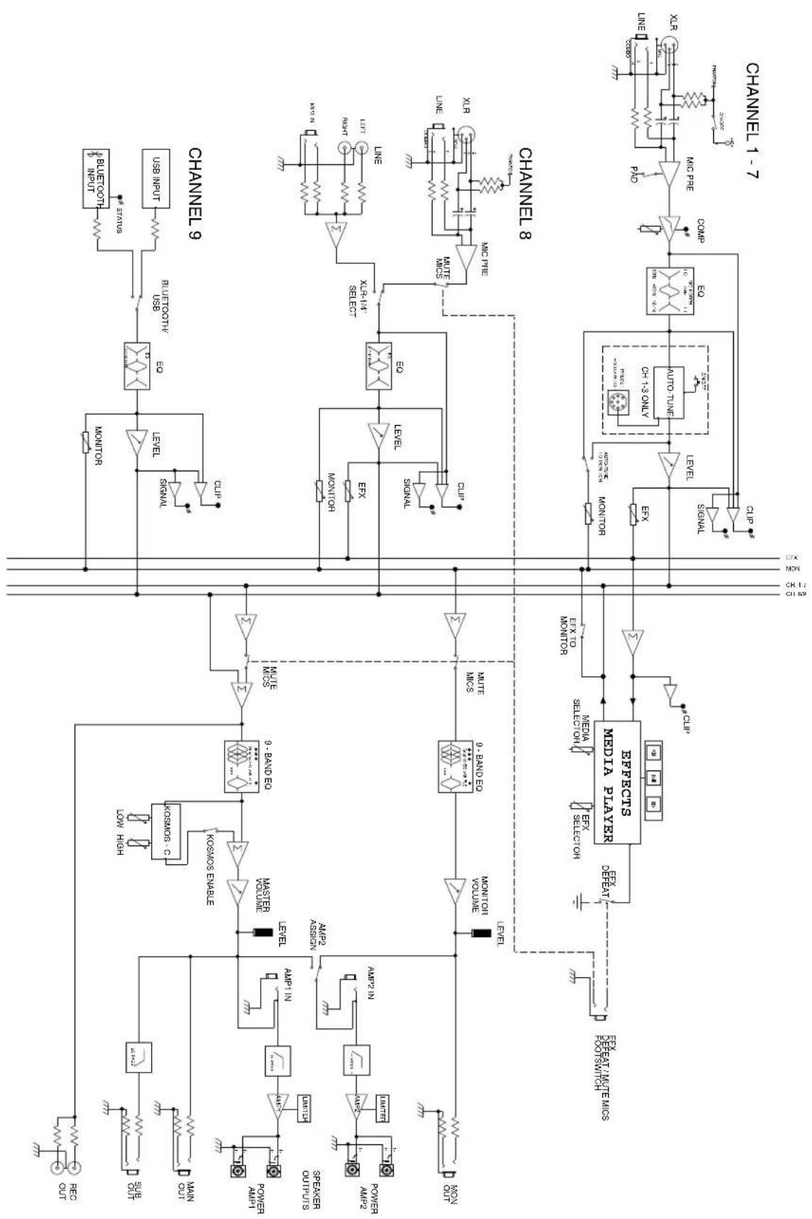
flowchart
graph TD
    subgraph Channel 9
        A["REC OUT"] --> B["Switch"]
        C["SUE OUT"] --> D["Switch"]
        E["MAIN OUT"] --> F["Switch"]
        G["POWER AM1"] --> H["Switch"]
        I["POWER AM2"] --> J["Switch"]
        K["Power OUTP1S"] --> L["Switch"]
        M["Switch"] --> N["Switch"]
        O["Switch"] --> P["Switch"]
        Q["Switch"] --> R["Switch"]
        S["Switch"] --> T["Switch"]
        U["Switch"] --> V["Switch"]
        W["Switch"] --> X["Switch"]
        Y["Switch"] --> Z["Switch"]
        AA["Switch"] --> AB["Switch"]
        AC["Switch"] --> AD["Switch"]
        AE["Switch"] --> AF["Switch"]
        AG["Switch"] --> AH["Switch"]
        AI["Switch"] --> AJ["Switch"]
        AK["Switch"] --> AL["Switch"]
        AM["Switch"] --> AN["Switch"]
        AO["Switch"] --> AP["Switch"]
        AQ["Switch"] --> AR["Switch"]
        AS["Switch"] --> AT["Switch"]
        AU["Switch"] --> AV["Switch"]
        AW["Switch"] --> AX["Switch"]
        AY["Switch"] --> AZ["Switch"]
        BA["MAIN OUT"] --> BB["MAIN IN"]
        BC["MAIN IN"] --> BD["MAIN IN"]
        BE["MAIN IN"] --> BF["MAIN IN"]
        BG["MAIN IN"] --> BH["MAIN IN"]
        BI["MAIN IN"] --> BJ["MAIN IN"]
        BK["MAIN IN"] --> BL["MAIN IN"]
        BM["MAIN IN"] --> BN["MAIN IN"]
        BO["MAIN IN"] --> BP["MAIN IN"]
        BQ["MAIN IN"] --> BR["MAIN IN"]
        BS["MAIN IN"] --> BT["MAIN IN"]
        BU["MAIN IN"] --> BV["MAIN IN"]
        BW["MAIN IN"] --> BX["MAIN IN"]
        BY["MAIN IN"] --> BZ["MAIN IN"]
        CA["MAIN IN"] --> CB["MAIN IN"]
        CC["MAIN IN"] --> CD["MAIN IN"]
        DE["MAIN IN"] --> DF["MAIN IN"]
        DG["MAIN IN"] --> DH["MAIN IN"]
        DI["MAIN IN"] --> DJ["MAIN IN"]
        DK["MAIN IN"] --> DL["MAIN IN"]
        DV["MAIN IN"] --> DW["MAIN IN"]
        DX["MAIN IN"] --> DXB["MAIN IN"]
        DXB --> DXC["MAIN IN"]
    end

    subgraph Channel 8
        DB["MDBCTS MEDIA PLAYER"]
    end

    subgraph Channel 9
        E1["KOSMOS Enable"]
        E2["KOSMOS Enable"]
        E3["KOSMOS Enable"]
    end

    subgraph Channel 1-7
        DB
        DB
    end

    style Channel 8 fill:#f9f,stroke:#333
    style Channel 1-7 fill:#ccf,stroke:#333
Specifications
INPUT SENSITIVITY:
Mic In to full power at the power amp. Master Volume Nom.
Full Nominal
-40 dBu -22 dBu
Line In to full power at the power amp. Master Volume Nom.
Full Nominal
-10 dBu +8 dBu
CHANNEL EQ:
Shelving EQ
Low EQ 80 Hz ±15 dB
Mid-Morph
Low 250 Hz ±15 dB
High 4 kHz ±15 dB
High EQ 12 kHz ±15 dB
CLIP LED:
Clip LEDs come on 3 dB before clipping.
FREQUENCY RESPONSE:
All controls nominal (detent)
Mic to Main 20 Hz - 20 kHz +0, -1 dB
Line to Main 20 Hz - 30 kHz +0, -1 dB
Mic to Amp 50 Hz - 20 kHz +0, -3 dB
Line to Amp 40 Hz - 20 kHz +0, -3 dB
PHANTOM POWER:
+48 VOLTS
NOISE:
Main = Main line output, 22 - 22 kHz filter
Amp 1 = Amplifier output, loaded at 4 Ohms, through AP
AUX-0025 switching amplifier filter
All controls full down.
Main <-95 dBu
Amp 1 <-60 dBu
Master Volume nominal
Main <-88 dBu
Amp 1 <-55 dBu
THD:
All controls nominal
<0.01% @ main line output, -30 dBu in mic input Channel 1
<0.5% @ amp 1 @ 400 Watts into 4 Ohms
All controls nominal
<0.005% @ main line output, +4 dBu in line input Channel 1
<0.5% @ amp 1 @ 400 Watts into 4 Ohms
MASTER EQ:
Limits amplifier power just before clipping. The limiter holds the amp power without clipping and can be driven up to 18 dB past maximum output.
AMPLIFIER OUTPUT POWER:
120VAC
Both channels loaded at 8 ohms: 280 Watts RMS per ch
Both channels loaded at 4 ohms: 500 Watts RMS per ch
POWER REQUIREMENTS:
Domestic: 120VAC 50/60Hz 200 Watts Nominal
Export: 230VAC 50/60Hz 200 Watts Nominal
SIZE:
| Dimensions: | H x W x D |
| 11.25" x 19.375" x 10.75" | |
| 285.75mm x 492.12mm x 273.05mm |
WEIGHT: 22.2 lbs.
10.07 kgs
SUBPART J OF FCC RULES. THIS DEVICE COMPLIES WITH PART 15 OF THE FCC RULES. OPERATION IS SUBJECT TO THE FOLLOWING TWO CONDITIONS (1) THIS DEVICE MAY NOT CAUSE HARMFUL INTERFERENCE, AND (2) THIS DEVICE MUST ACCEPT ANY INTERFERENCE RECEIVED, INCLUDING INTERFERENCE THAT MAY CAUSE UNDESIRED OPERATION.

Features and specifications subject to change without notice.
Peavey Electronics Corporation • 5022 Hartley Peavey Drive • Meridian, MS • 39305
(601) 483-5365 • FAX (601) 486-1278 • www.peavey.com • 31700107 • ©2015

Logo referenced in Directive 2002/96/EC Annex IV
(OJ(L)37/38,13.02.03 and defined in EN 50419: 2005
The bar is the symbol for marking of new waste and
is applied only to equipment manufactured after
13 August 2005
Notes
Notes
Notes

natural_image
Abstract black geometric logo design with stylized arrow-like shapes (no text or symbols)www.peavey.com
Warranty registration and information for U.S. customers available online at
www.peavey.com/warranty
or use the QR tag below

Features and specifications subject to change without notice.
Peavey Electronics Corporation
5022 Hartley Peavey Drive Meridian, MS 39305 (601) 483-5365 FAX (601) 486-1278

Logo referenced in Directive 2002/96/EC Annex IV (OJ(L)37/38,13.02.03 and defined in EN 50419: 2005
The bar is the symbol for marking of new waste and is applied only to equipment manufactured after 13 August 2005


- FC
- Caution
- ENGLISH
- XR ® -AT
- Powered Mixer
- Features:
- Channel Controls
- ① MIC/LINE INPUT (CH.1-8)
- PAD (CH. 1-7)
- MEDIA INPUTS (CH.8 RCA and 3.5mm)
- ④ INPUT SELECT SWITCH (CH. 8)
- ⑤ AUTO-TUNE ON/OFF (CH 1-3)
- COMPRESSOR AND COMP LED (CH 1-7)
- HIGH EQ
- MID-MORPH EQ (CH. 1-7)
- MID EQ (CH. 8 & 9)
- LOW EQ
- MONITOR SEND
- AUTO-TUNE TO MONITOR BUTTON (CH. 1-3)
- EFFECTS SEND (CH. 1-8)
- LEVEL
- CLIP
- SIG
- USB MEDIA JACK (CH. 9)
- USB PLAYBACK:
- MASTER CONTROLS FLS
- GRAPHIC EQ
- LEVEL LED LADDER
- MAIN LEVEL
- MONITOR LEVEL
- EFX TO MON
- POWER AMP 2 ASSIGN
- KOSMOS-C
- KOSMOS ENABLE
- MIC MUTE
- EFX DEFEAT
- EFX CLIP
- LCD DISPLAY
- REW/PREV
- PLAY/PAUSE
- FF/NEXT
- EFX SELECT/AUTO-TUNE ADJUST
- EDIT AUTO-TUNE
- MEDIA SELECT
- CH 9 INPUT SELECT (USB/BLUETOOTH)
- BLUETOOTH ACTIVE LED
- EFX Mode
- Auto-Tune Mode:
- Note:
- Bluetooth® Player
- Inputs/Outputs
- POWER SWITCH
- FUSE
- AC POWER INLET
- NOTE: FOR UK ONLY
- FOOTSWITCH EFFECTS DEFEAT (TS)
- AUTO-TUNE FOOTSWITCH
- PEAVEY 5-BUTTON MIDI FOOTSWITCH
- MIDI
- MIDI CC:
- MIDI PROGRAM:
- Effects (parameter)
- Specifications
- INPUT SENSITIVITY:
- CHANNEL EQ:
- CLIP LED:
- FREQUENCY RESPONSE:
- PHANTOM POWER:
- NOISE:
- THD:
- AMPLIFIER OUTPUT POWER:
- POWER REQUIREMENTS:
- SIZE:
- Notes
- www.peavey.com
Brand : PEAVEY
Model : XR-AT
Category : Blender