
7160-0318-04 - Computer Accessories Gamber-Johnson - Free user manual and instructions
Find the device manual for free 7160-0318-04 Gamber-Johnson in PDF.


| Product Type | Laptop / Tablet Mount |
| Brand | Gamber-Johnson |
| Model | 7160-0318-04 |
| Compatible Devices | Laptops and tablets up to 15.6 inches |
| Mounting Type | Vehicle seat bolt or floor mount |
| Material | Steel and high-impact plastic |
| Weight Capacity | 15 lbs (6.8 kg) |
| Dimensions (L x W x H) | 12 x 10 x 4 inches (30.5 x 25.4 x 10.2 cm) |
| Weight | 5 lbs (2.3 kg) |
| Color | Black |
| Adjustment | Tilt, swivel, and rotation |
| Rotation Range | 360 degrees |
| Tilt Range | -10 to +90 degrees |
| Swivel Range | 180 degrees |
| Installation Method | Bolt-on with included hardware |
| Tools Required | Socket wrench, Phillips screwdriver |
| Warranty | Limited lifetime warranty |
| Country of Origin | USA |
| Package Contents | Mounting base, laptop tray, hardware kit, instruction manual |
| Safety Features | Locking tension knobs, anti-vibration pads |
| Maintenance | Wipe clean with dry cloth; lubricate joints annually |
Frequently Asked Questions - 7160-0318-04 Gamber-Johnson
User questions about 7160-0318-04 Gamber-Johnson
0 question about this device. Answer the ones you know or ask your own.
Ask a new question about this device
Download the instructions for your Computer Accessories in PDF format for free! Find your manual 7160-0318-04 - Gamber-Johnson and take your electronic device back in hand. On this page are published all the documents necessary for the use of your device. 7160-0318-04 by Gamber-Johnson.
USER MANUAL 7160-0318-04 Gamber-Johnson
INSTALLATION INSTRUCTIONS
Form Product Re
7160-0318-00 THROUGH 7160-0318-12
REV. K INST-509
PANASONIC TOUGHBOOK CF-31 DOCKING STATION
Printing Spec: PS-001
This instruction sheet is for the following products:
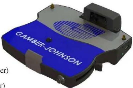
Panasonic Toughbook CF-31 docking station with NO integrated high gain antenna pass-thru cables.
Item No. 7160-0318-00 (-P) (button lock, No RF)
Item No. 7160-0318-04 (-P) (button lock, No RF, Int. power)
Item No. 7160-0318-07 (-P) (Auto lock, No RF)
Item No. 7160-0318-10 (-P) (Auto lock, No RF, Int power)
Panasonic Toughbook CF-31 docking station with single integrated high gain antenna pass-thru cable.
Item No. 7160-0318-01 (-P) (Button lock, Single RF)
Item No. 7160-0318-05 (-P) (Button lock, Single RF, Int power)
Item No. 7160-0318-08 (-P) (Auto lock, Single RF)
Item No. 7160-0318-11 (-P) (Auto lock, Single RF, Int. power)
natural_image
3D model of a blue and gray electronic device labeled 'GAMBER-JOHNSON' (no additional text or symbols visible)Panasonic Toughbook CF-31 docking station with dual integrated high gain antenna pass-thru cable.
Item No. 7160-0318-02 (-P) (Button lock, Dual RF)
Item No. 7160-0318-06 (-P) (Button lock, Dual RF, Int power)
Item No. 7160-0318-09 (-P) (Auto lock, Dual RF)
Item No. 7160-0318-12 (-P) (Auto lock, Dual RF, Int. power)
* These instructions are for the docking station only. For instructions on features, set-up and operation of the Toughbook CF-31 computer, please refer to the manuals provided by Panasonic with the computer.
** This docking station is designed to be used with a variety of Gamber Johnson mounting systems. Installation for other Gamber Johnson products are provided with each individual product.
*** This device is Class B verified to comply with Part 15 of FCC Rules when used with a Panasonic Toughbook CF-31 computer. To assure continued compliance, use only shielded interface cables when connecting a peripheral to the docking station.
CF-31 DOCKING STATION FEATURE IDENTIFICATION


IMPORTANT SAFETY INFORMATION FOR INSTALLERS
Safety is dependent on the proper installation and servicing of this docking station. It is important to read and follow all instructions before installing this product.
To properly install Gamber Johnson docking station you must have a good understanding of automotive electrical procedures and systems, along with proficiency in the installation and service of aftermarket vehicle equipment.
There are no adjustments required at any time of the electrical components within the docking station. Opening the port replication housing will void the product warranty.
During Installation:
DO NOT connect this docking station to the vehicle battery until:•
ALL other electrical connections are made1.
Mounting of ALL components is complete2.
VERIFICATION that no shorts exist in the entire system3.
DO NOT install equipment or route wiring or cords in the deployment path of any airbag.
When drilling into the vehicle. DO make sure that both sides of the surface are clear of anything that could be damaged.
CAUTION: If wiring is shorted to the frame, high current conductors can cause hazardous sparks resulting in electrical fires or flying molten metal.
After Installation:
Test the docking station to ensure that it is working properly.
File these instructions in a safe place and refer to them when performing maintenance or re-installing.
WARNING: Failure to follow all safety precautions and instructions may result in property damage, serious injury or death.
PRE-INSTALLATION RECOMMENDATIONS
Conduct a "Bench Test"
Gamber Johnson strongly advises a "Bench Test" be conducted to verify that all electronic and software issues are resolved prior to installation:
Make sure computer is operational by itself.1.
Insert computer into docking station and verify that the computer is operating in the dock.2. Interconnect entire assembly and verify start-up of all components, including other equipment 3. (printers, modems, scanners, etc.)
*Gamber Johnson recommends positioning of all mounts and equipment in the vehicle prior to the actual install to verify that mounting locations are safe and practical.
MOUNTING THE DOCKING STATION
Mount docking station to mounting system using the four 1/4-20 UNC mounting holes on the bottom of the dock. Four 1/4-20 UNC x .50 Button Head Mounting Screws are provided in the hardware bag.
* Recommended torque: 75 in-lbs. Over tightening mounting hardware may damage docking station.
* Use of hardware longer than 5/8" may damage docking station.
This docking station is designed to be used with a variety of Gamber Johnson mounting systems. Installation instructions for other Gamber Johnson products are provided with each individual product.

When attaching clevis to the dock make sure the orientation is as shown in picutre to the left. Otherwise clevis will interfere with support bracket and ports. If desired handle can be switched to opposite side for convenience.
Clevis (Not Included)
Use 1/4-20 x.50 (Qty. 4) Button Head Mounting Screws.
WIRELESS ANTENNA SWITCH
If wanting to use external antenna, connected by cable to the WAN port on the dock: Position the switch toward the "EXT" side.
If wanting to use antenna built into the computer or PC Card type antenna: Position the switch toward the "INT" side.
CF-31MK1 computers are not effected by the "Antenna Switch". To disable external antenna on all CF-31 MK1 computers, install Panasonic service part No. (DFHR3S40ZA, DFHR3S39ZA or DFHR3S38ZA (dual) over the RF connection on back of the computer. This part can be ordered from Panasonic (1-800-527-8675) and support will send request to service department. If the CF-31 Model No. is followed by the following Alpha's you know it is a MK1 model: CF-32A, B/E, C, D or G. All other CF-31 models work as stated above.

CABLE RESTRAINT INFORMATION
Retain the USB and Ethernet cables at the Restraint Bracket using the supplied cable ties. If desired additional cables can be routed and attached to Restraint Bracket with cable ties.
USB/Ethernet Restraint Bracket

natural_image
Close-up of a mechanical device with visible components and mounting holes (no text or symbols)POWER SUPPLY INFORMATION
(NON INTERNAL POWER SUPPLY MODELS)
Panasonic recommends using a Lind Auto Adapter (Lind part No. PA1580-2961) to power the docking station. It can be ordered from Gamber Johnson (part No. 14103) or directly from Lind Electronics, Minneapolis, Minnesota (952-927-6303).
Installation of the Power Jack:
With cable of Power Jack oriented perpendicular to the bottom of the dock insert Power Jack into socket labeled DC IN 15.6V. After Power Jack is inserted into socket rotate Power Jack towards LAN/WAN labels to lock Power Jack into socket. Insert cable between snap finger and frame and secure with cable clamp and screw. See image below for correct position of cable to maximize space around RF connector, if dock is so equipped.

(INTERNAL POWER SUPPLY MODELS)
This docking station has an add on power supply and is designed to be used with a 12 volt or 24 volt DC systems only. The voltage output is factory set at 15.6 volts.
WIRING INSTRUCTIONS
IMPORTANT: Make sure that you have read this entire section before you begin wiring! Refer to Figure 1
- Install docking station into vehicle, making sure that all bolts are tight.
- Attach BLACK ground wire to the location where the vehicle battery grounds to vehicle chassis.(See Figure 1)
- Connect the RED wire to the supply voltage (V+) from the vehicle. (See Figure 1)
IMPORTANT REMINDERS:
- Use only SAE J1128 Type GPT number 16 AWG stranded wire (minimum) to attach the docking station to the vehicle's electrical system.
- Connect lead wires to the Docking Station (recommend using quick disconnects as shown in Figure 1) Caution: The disconnect must be easily accessible. When assembling the quick disconnects, use only Panduit crimp tools CT-100, CT-600, CT-1525, CT-1550 or CT-1551.
- Route the lead wires to the battery. Total wire in the circuit must not exceed 30 feet and must conform to SAE J1128 standard.
- Protect the lead wires from abrasion and chafing by using wire loom or conduit and route away from moving parts or areas where high temperatures may occur.
- Connection of the supply voltage (V+) must be kept as close to the battery as possible.
- The power connection must be made with the 10 amp in-line fuse and fuse holder provided with the dock. Connect the fuse holder to the lead wire using the butt splice connectors provided with the fuse holder. When assembling the butt splice connectors, use only Panduit crimp tools CT-100, CT-600, CT-1525 or CT-1551.
The fuse holder location must be kept within 10 inches of the connection to the battery positive, away from moving parts and temperatures that exceed 180 degrees F.
Caution: If the fuse holder requires replacement, it should be replaced by qualified service personal using Littlefuse part number FHM1 (Gamber-Johnson part number 11689). This device conforms to ASTM D471 and SAE J1128 standards. - Fuse must be inserted in the supplied fuse holder. Caution: For continued protection against risk of fire, replace only with the same type and rating of supplied fuse. The provided fuse is UL Listed, rated at 10 amps, 32 volt AC/DC fast acting.
- If a timing device is used, follow the instructions of the manufacturer of that device. It must be wired in-line with the supply voltage (V+) to the docking station.
- If you have any installation questions, please call Gamber-Johnson customer support at 1-800-456-6868.

flowchart
graph LR
    A["Ground to Vehicle Chassis"] --> B["16 AWG (black wire)"]
    B --> C["Fuse"]
    C --> D["Panduit # DNF14-250FIB Quick Disconnect (female) to black lead from dock."]
    C --> E["Panduit # DNF14-250FIB Quick Disconnect (male) to black lead from battery."]
    C --> F["Panduit # DNF14-250FIB Quick Disconnect (male) to red lead from battery."]
    C --> G["Panduit # DNF14-250FIB Quick Disconnect (female) to red lead from dock."]
    C --> H["Panduit # DNF14-250FIB Quick Disconnect (male) to red lead from battery."]
    I["Vehicle Battery"] --> J["- +"]
    J --> K["10""]
    K --> L["Fuse"]
    L --> M["16 AWG (red wire)"]
    M --> N["Panduit # DNF14-250FIB Quick Disconnect (female) to red lead from dock."]
    M --> O["Panduit # DNF14-250FIB Quick Disconnect (male) to red lead from battery."]
DOCKING THE COMPUTER
Shut down the computer.1.
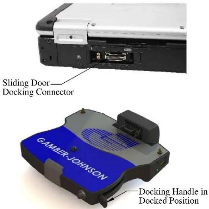
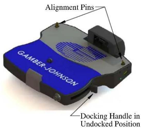
- Make sure the sliding door (located on the back of the computer has been fully opened, exposing the computer's docking connector. Make sure the Docking Handle is in the Undocked Position.
Set computer in the dock:3.
a. Hook the front of the computer on the front retainer.
b. Lower the back of the computer onto the Alignment Pins.
c. Lightly press down on the back of the computer to ensure it is fully seated.
- Pull the Docking Handle towards the front of the dock until the latch catches (Docked Position). The push button can be locked for security.
Boot the computer. If the dock is powered, the computer is powered and ready for use.5.
Caution: Without a computer in place the Docking Handle is locked in the Undocked Position. DO NOT actuate the Docking Handle without a computer correctly positioned on the dock. Damage may occur.
* Docking station will operate with the computer screen opened or closed.
REMOVING COMPUTER FROM DOCK
Shut down computer.1.
Auto Lock: Insert key and rotate clockwise.2.
Button Lock: Unlock with key if locked. Push button in until Docking Handle releases.
Lift back of the computer off the locating pins.3.
Lift the computer out from under the Front Retainer.4.
DOCKING INDICATOR LED
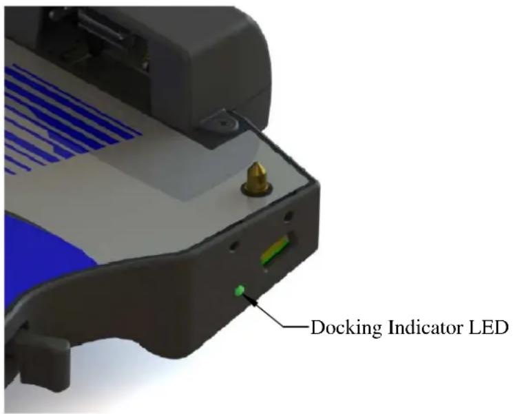
The Docking Indicator LED is located on the right hand side of the dock. With the computer installed in the dock the Docking Indicator LED can be used as a troubleshooting tool.
GREEN: All ports are ready to use.
ORANGE: USB port and LAN port do not function, external power is not connected.
RED: PC is not supported or connection is not made.
RED (BLINKING): Error has occurred in the firmware. Stop using at once and contact Panasonic Technical Support.
NOT LIT: PC not installed or PC is OFF, Standby or Hibernation.
ETHERNET PORT INFORMATION
Ethernet ports #1 and #2 will both function when a Panasonic Toughbook CF-31 computer is used with one of the 7160-0318-XX series Docking Stations. Gamber Johnson recommends using Ethernet port #2 with a Panasonic Toughbook CF-31.
Only Ethernet port #1 will work if a Panasonic Toughbook CF-30 computer is used with one of the 7160-0318-XX series Docking Stations. See page 2 for port locations.
COMPUTER SERIAL PORT
NOTE: Serial port on back side of CF-31 computer will not function when computer is attached to Docking Station.

natural_image
Close-up of a mechanical electronic component with a red circle highlighting a port (no visible text or symbols)This serial port will not function when CF-31 is attached to Docking Station
DRIVERS
If needed, the software driver for this product can be downloaded from Panasonic's Support Page: http://www.panasonic.com/business/toughbook/computer-support-search-downloads.asp

- INSTALLATION INSTRUCTIONS
- IMPORTANT SAFETY INFORMATION FOR INSTALLERS
- During Installation:
- After Installation:
- PRE-INSTALLATION RECOMMENDATIONS
- Conduct a "Bench Test"
- MOUNTING THE DOCKING STATION
- WIRELESS ANTENNA SWITCH
- CABLE RESTRAINT INFORMATION
- POWER SUPPLY INFORMATION
- Installation of the Power Jack:
- (INTERNAL POWER SUPPLY MODELS)
- WIRING INSTRUCTIONS
- IMPORTANT REMINDERS:
- DOCKING THE COMPUTER
- REMOVING COMPUTER FROM DOCK
- DOCKING INDICATOR LED
- ETHERNET PORT INFORMATION
- COMPUTER SERIAL PORT
- DRIVERS
Brand : Gamber-Johnson
Model : 7160-0318-04
Category : Computer Accessories