
GAS4RO - Cooker Infiniton - Free user manual and instructions
Find the device manual for free GAS4RO Infiniton in PDF.


| Product Type | Gas Cooker (some models include electric hot plates) |
| Brand | Infiniton |
| Model | GAS4RO |
| Dimensions (Overall, approx.) | 590 x 520 x 40 mm (L x P x H for 60 cm series, excluding knobs) |
| Cut-out Dimensions (for built-in) | 560 x 490 mm (for 60 cm series) |
| Number of Gas Burners | 4 (Auxiliary, Medium Quick, Quick, Triple Ring) |
| Gas Burner Power (Max) | Triple Ring: 3.1 kW, Quick: 2.8 kW, Medium Quick: 1.7 kW, Auxiliary: 0.95 kW |
| Gas Supply Type | Natural Gas (G20) or LPG (G30/G31) – adjustable via injector replacement |
| Electrical Supply | 220-240 V ~ 50/60 Hz (for ignition and optional electric hot plates) |
| Ignition | Electric spark ignition (some models with separate ignition button) |
| Safety Valve | Yes, on each burner (on models so equipped) – shuts off gas if flame goes out |
| Electric Hot Plates (Optional) | May include one or more normal, quick, or automatic hot plates (red dot or center plate) |
| Control Knobs | Rotary knobs for burner flame adjustment and electric hot plate control (if present) |
| Material | Enameled steel or stainless steel hob with glass option |
| Cleaning | Use warm water and mild detergent; avoid abrasives. Burner parts can be washed in dishwasher. Do not use steam cleaners. |
| Safety Warnings | Do not leave unattended with oil/fat; keep children away; do not use if glass cracked; connect to grounded outlet; ensure ventilation. |
| Gas Connection | 1/2" male threaded connection; use rigid metal pipe or flexible stainless steel hose (max 2 m) with gaskets |
| Adaptation to Different Gases | Replace injectors (supplied) and adjust minimum flame; LPG requires tightening bypass screw |
| Minimum Distance from Hanging Cabinet | At least 600 mm above hob |
| Spare Parts | Original spare parts available from authorized Technical Service Centres |
| Compliance | EU Directives: Low Voltage, EMC, WEEE, ErP, RoHS, Gas Appliances (GAR) |
Frequently Asked Questions - GAS4RO Infiniton
User questions about GAS4RO Infiniton
0 question about this device. Answer the ones you know or ask your own.
Ask a new question about this device
Download the instructions for your Cooker in PDF format for free! Find your manual GAS4RO - Infiniton and take your electronic device back in hand. On this page are published all the documents necessary for the use of your device. GAS4RO by Infiniton.
USER MANUAL GAS4RO Infiniton
Before leaving the factory, this appliance was tested and regulated by expert and skilled personnel to give the best operating results. Any repair or regulation that may subsequently be necessary must be carried out with the greatest care and attention. For this reason, we recommend you always contact the Dealer you bought the appliance from or our nearest Service Centre, specifying the type of problem and the model of your appliance. Please remember as well that the original spare parts are available only from our Technical Service Centres. Do not leave the packaging unguarded, both for the safety of children and for the protection of the environment, but dispose of it in a centre for differentiated waste.

The symbol on the product or on the packaging means that the product must not be considered as normal household refuse, but must be taken to the appropriate collection point for the recycling of electric and electronic equipment. The appropriate disposal of this product helps avoid potential negative consequences on the environment and for health, which could be caused by inappropriate disposal of the product. For more detailed information on the recycling of this product, please contact your municipal offices, the local waste disposal service or the store where the product was purchased.
TABLE OF CONTENTS
GENERAL WARNINGS
pag. 2-4
Instructions for use:
• Description of the main parts of the appliance pag. 5
• Gas burners (operation, lighting, advice)
• Operation of electric hot plates
- Maintenance and cleaning
pag. 6-7
pag. 8
pag. 9
Instructions for installation:
- Positioning and gas connection
• Electrical connection - Adaptation to different types of gas
- Instructions for building in the units
pag. 10-11
pag. 12
pag. 13-15
pag. 16-17
General warnings
Dear Customer,
Thank you for having chosen one of our products. This appliance is easy to use, but you must read this booklet carefully before installing and using it. The booklet contains instructions that will help you to install, use and service the product in the best way.
WARNING: This appliance and its accessible parts become very hot during use. Take care and do not touch the heating elements. Unless they are supervised at all times, children younger than 8 years of age must be kept well away from the appliance.
WARNING: This appliance may be used by children from 8 years of age onwards and by persons with reduced physical, sensorial or mental capabilities, or who lack experience and knowledge so long as they are properly supervised or have been trained on how to use the appliance safely and are aware of the risks involved. Children must not play with the appliance. The appliance must not be cleaned or serviced by unsupervised children.
WARNING: Do not leave a hob unattended when fat or oil is being used. This could be dangerous and cause a fire.
WARNING: NEVER attempt to put out a fire/flames with water. Switch off the appliance
General warnings
and cover the flame with a lid or a blanket made of fire-retardant material for example.
WARNING: Fire risk. Do not leave objects on the surface of the hob.
WARNING: If the glass or glass-ceramic surface is cracked, switch off the appliance to prevent the risk of an electric shock.
The appliance cannot be switched on by an external timer or a separate remote control.
Do not use jets of steam to clean the appliance.
It is very important for this instruction booklet to be kept with the appliance if it changes hands.
These instructions are only applicable in countries whose pictograms appear on the cover and on the appliance itself.
This appliance has been designed for non-professional use by private individuals in their homes and its purpose is to cook and heat food. Do not use it for other purposes.
The appliance must be installed by a skilled and qualified installer who is familiar with the installation rules in force.
Before it is cleaned or serviced, the appliance must be disconnected from the electric power source and allowed to cool.
Before you switch on the appliance, make sure that it has been correctly regulated for the type of gas available in your area (consult the relative section).
When you turn on the burners, always make sure that the flame is regular.
If a burner goes out accidentally, turn off the control knob and wait at least one minute before turning it on again.
It is advisable to switch off the relative heating element before you remove the saucepans.
General warnings
The electric power cable of the appliance must not be replaced by the user. It must only be replaced by a qualified electrician.
When used, gas-fired appliances produce heat and humidity in the room where they are installed. Make sure that this room is properly ventilated by keeping the natural air vents open or by installing a extractor hood with exhaust duct.
Additional ventilation may be required (by opening a window or increasing the degree of forced ventilation) when gas-fired appliances are used for long periods of time.
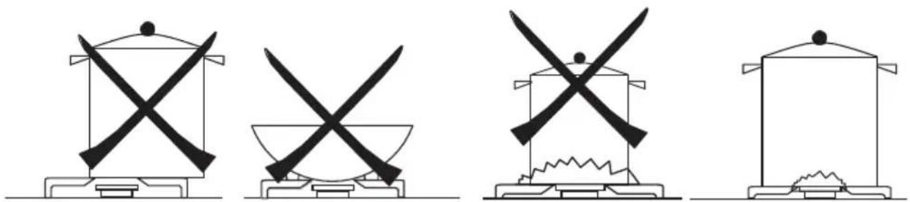
Make sure that you do not place unstable or deformed saucepans on the burner or electric hotplates. They could overturn or overflow and cause accidents.
Always use saucepans with suitable diameters for the cooking zones. Never use pans with smaller diameters than the cooking zones and never switch on the cooking zones without pans on them.
Make sure that you do not place unstable or deformed saucepans on the heating surfaces. They could overturn or overflow and cause accidents. Do not switch on the cooking zones without saucepans on them.
natural_image
Four identical line drawings of a cooking pot with crossed blades, arranged in a row (no text or symbols)Always call an authorized Technical Assistance Center and insist on original spare parts if repairs are required. Repairs made by incompetent persons could cause damage.
The appliance is switched off when all its knobs have been turned to position 0 / .●
- The appliance is conform to the following European Directives and Regulations: Directive 2014/35/EC (Low Voltage Appliances) Directive 2014/30/EC (ElectroMagnetic Compatibility) Directive 2012/19/EC (WEEE - Waste Electrical and Electronic Equipment) Directive 2009/125/EC (ErP - Eco Design) Directive 2011/65/EC (RoHS - restriction of hazardous substances) Regulation 1935/2004/EC (Materials intended to come into contact with food) Regulation 1907/2006/EC (REACH – Restriction of Chemicals) Regulation 2016/426/EC (GAR - Gas Appliances)
Instructions for use
Description of the main parts of the appliance
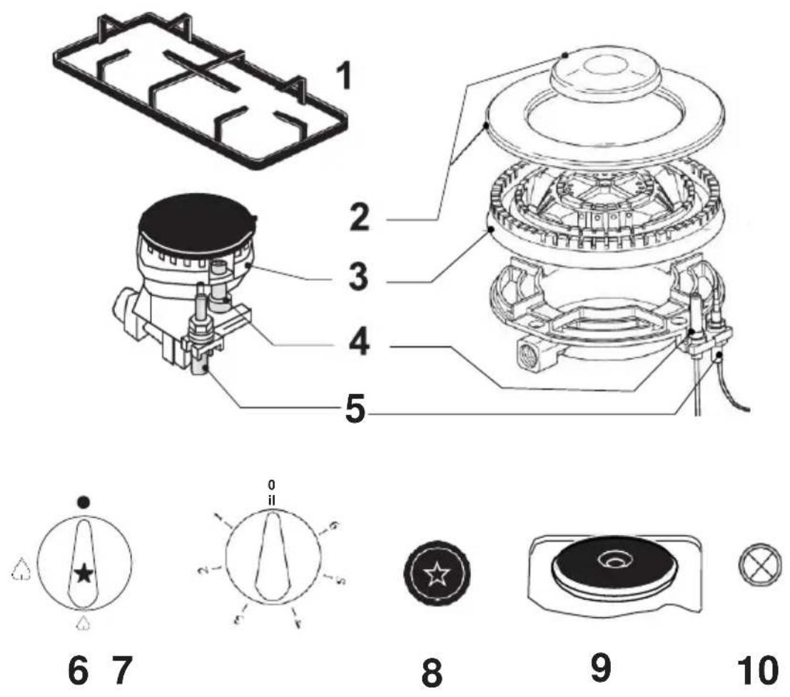
1 = grid
2 = cover
3 = spreader
4 = ON spark plug (for versions with lighting)
5 = safety valve (for models equipped with a safety valve)
6 = knob for burner ignition and adjustment (* ON switch on the knob for the versions so equipped)
7 = electric hot plate control knob
8 = separate ON switch (for the versions so equipped)
9 = electric hot plate (where there is one)
10 = electric hot plate operation pilot lamp
Instructions for use
The hob control area houses the devices and knobs for operation of the gas burners and/or the electric hot plates.
Operation of gas burners
The burner regulation knobs can be turned anticlockwise from the closing position to the widest open position and vice versa in the opposite direction (put the needle to the position required):
$$ \begin{array}{l} ⓞ = \text { no gas supply } \ ⓜ = \text { maximum gas supply } \ ↳ = \text { minimum gas supply } \ \end{array} $$
Lighting the burners
For models equipped with electrical ignition device, the ignition of burners takes place by pressing and rotating the knob until the position of maximum output is reached. In the versions with separate ignition key, only press this key and at the same time press and rotate the knob proportional to the desired burner, until it reaches the position of maximum output.
For versions without electric lighting (or if there is a power cut) perform the operations described using a match or lighter to light the gas (in such an event, pay the utmost attention not to burn yourself).
For models with safety valve keep the knob pressed for about 3-4 seconds until the device keeps the flame alight automatically.
The safety valve operates when the flame is turned off accidentally, stopping the supply of gas (e.g. in draughts, spills of liquid, etc.).
The ignition device shouldn't anyhow be operated for more than 15 seconds.
If a burner is turned off accidentally or does not light, turn the control knob OFF and repeat the lighting after at least 1 minute.
When the burner is lit adjust the flame as required.
To turn the gas supply OFF turn the knob clockwise to the << ● >> position.
Instructions for use
Advice on the use of gas burners
For lower gas consumption and a better yield, use saucepans with diameter suitable for the burners, avoiding the flame coming up round the side of the saucepan (see the Container Table). Use only flat-bottomed pans.
As soon as a liquid starts to boil, turn the flame down to a level sufficient to maintain boiling.
During cooking, when using fats and oils, be very careful because if they overheat they could catch fire.
Take care that the containers don't escape from the edges of the plan and don't invade the control panel.
Container table (use flat-bottomed saucepans)
| Burners (heights cover) mm | ∅ min. Saucepan (mm) | ∅ max. Saucepan (mm) |
| Auxiliary (∅ = 55) | 80 | 140 |
| Medium quick (∅ = 75) | 140 | 200 |
| Quick (∅ = 100) | 200 | 240 |
| Triple ring (∅ = 132) | 240 | 280 |
Instructions for use
Operation of electric hot plates
Some versions have one or more electric hot plates. These hot plates can be normal, quick or automatic. The last two types have a red dot in the centre (quick) and a circular plate in the centre (automatic).
The hot plates can be adjusted depending on cooking requirements, turning their knobs clockwise or anticlockwise to 6 positions as well as 0. The positions marked with the highest number correspond to the greatest supply of heat (see table). With the quick and automatic hot plates, once the temperature selected has been reached, a thermostat automatically reduces the power and the hot plate will operate intermittently so that the temperature remains constant throughout cooking.
The indicator lamp on the control panel signals that the electric hot plates are switched on.
Advice on use of the hot plates
So that the electric hot plates last longer and to save energy, only use flat-bottomed saucepans whose diameter is not smaller than that of the hot plates.
Avoid boiling liquids spilling out of the saucepan on to the hot plates.
Do not leave the hot plates on empty or with empty saucepans and do not use them to heat the room.
Switch the hot plates on after you have put the saucepans on them.
Do not forget that when the hot plates are switched off they remain hot for some time.
| Reheating Cooking Roasting-frying | |||
| Electric hot plates | 1 | 2 | 3 |
Instructions for use
Maintenance and cleaning
Do not use jet of steam for cleaning.
Before any operation disconnect the appliance electrically. Wash the enamelled parts with lukewarm water and detergent. Do not use abrasive products.
Wash the burner spreader frequently with boiling water and detergent being sure to remove any deposits which could block the flame outlet. Rinse the stainless steel parts well with water and dry them with a soft cloth.
To clean the hob use slightly damp sponges and wiping cloths: if too much water is used it could penetrate the internal parts and damage electrical parts.
The grids of the hob can be washed in the dishwasher.
For persistent stains use normal non-abrasive detergents, specific products commonly available on the market or a little hot vinegar. Clean the glass hob with hot
water, avoiding the use of rough cloths.
Do not use stainless steel pads or acids for cleaning.
To prevent lighting difficulties, carefully clean the lighting spark plugs regularly (ceramic and electrode).
To clean the electric hot plates use damp wiping cloths and grease slightly with a little oil when the hot plate is still lukewarm.
Periodically, or if the knobs become difficult to turn, contact a qualified engineer to lubricate the taps.
Contact a qualified engineer to deal with any other problems which may arise during use.
natural_image
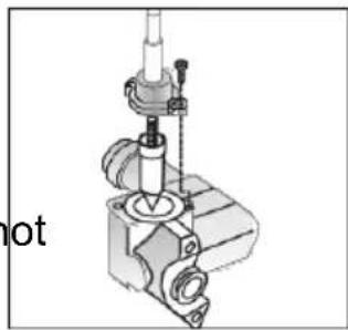
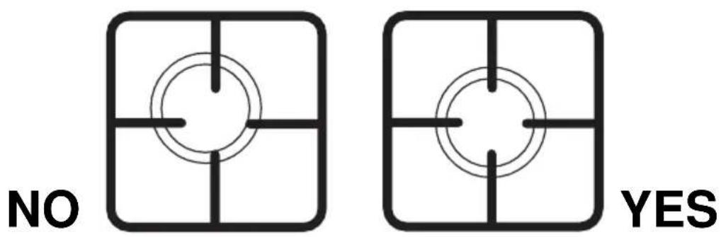
Mechanical assembly diagram showing a cylindrical component mounted on a base with a tool and valve (no text or symbols visible)Important. IN CASE OF BURNERS REMOVAL FOR CLEANING PURPOSES, WE RECOMMEND TO MAKE SURE THAT ALL PARTS ARE CORRECTLY POSITIONED BEFORE IGNITING THE BURNERS AGAIN.AFTER A POSSIBLE GRID REMOVAL FOR CLEANING AND/OR MAINTENANCE NEEDS, WE RECOMMEND TO VERIFY THE PRESENCE OF SUCH RUBBER PADS AND TO PUT THE GRIDS BACK IN THEIR STABLE AND CENTRED CORRECT POSITION.
Instructions forinstallation
Below we give the instructions for qualified installers so that the installation, setting and maintenance operations are performed correctly and according to the regulations in force.
Positioning
This appliance isn't connected to any scavenging devices of combustion products.
The appliance can only be installed and operate in permanently ventilated rooms according to the local regulations in force.
The natural flow of air must be direct through permanent holes made in the walls of the room to be ventilated leading to the outside, or through single or collective branched ventilation ducts.
The ventilation openings must have a effective cross-section of at least 100 cm ^2 and must be protected against accidental blocking (protection with metal grills or grids). For appliances without safety valve on the hob, the opening section is doubled with a minimum of 200 cm ^2 .
There may also be an indirect flow of air from rooms next to that where the appliance is installed, as long as these rooms have direct ventilation, there is no fire risk in these rooms and they are not bedrooms.
The flow of air between adjacent room and the room where it is installed must be free through permanent openings (which may be obtained by making the gap between door and floor larger).
In the room where it is installed there must be a system for leading the combustion fumes to the outside. This may be with a hood or an electric fan which switches on when the appliance is switched on.
Gas connection
The appliance must be connected to the gas supply or the cylinder according to the specifications of the standards in force and after checking that it is adjusted for the type of gas available.
The appliance is set up to operate with the gas specified on the calibration label placed both on the packaging and on the back of the appliance.
When the type of gas available does not correspond to that for which the appliance is set up, replace the corresponding injectors (provided), being careful to put on the new calibration label (provided) and remove the old one.
Instructions forinstallation
To perform these operations the qualified installer will follow the indications given in the "Adaptation to the various types of gas" section.
For safety operation make sure that the supply pressure respects the values given in the "Table of burner and injector characteristics".
If the appliance is supplied with liquid cylinder gas, make sure that the cylinder pressure regulator conforms to the local regulations in force.
The appliance must be connected to the gas system by a rigid metal pipe (copper or steel) or continuous wall stainless steel flexible hose in such a way that the appliance is not stressed in
any way.
The appliance gas inlet tube has an end nut to which is connected the elbow union (supplied; 1/2 thread male gas). It can be turned depending on installation needs.
The rigid or flexible metal supply pipe (I max = 2mt) is connected to the part opposite the elbow union. Remember to put the gaskets supplied at the two ends of the elbow union.
When these parts are disassembled and reassembled, always replace the gaskets with new ones.
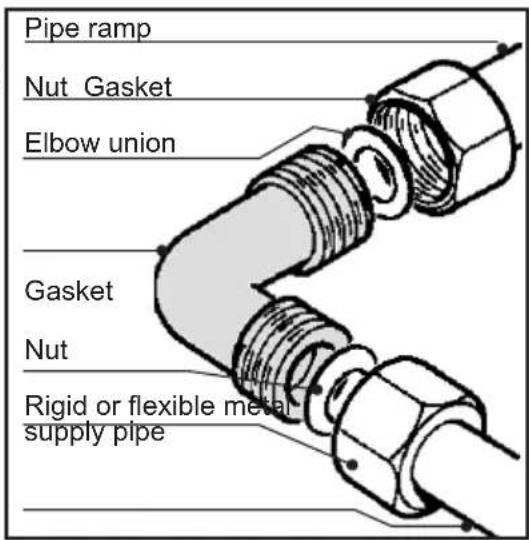
Once the appliance is installed, check that the gas pipe is not pinched or damaged by mobile parts.
Important: when installation is complete, check that all the gaskets are leaktight using a soap-based solution, never a flame.
Instructions forinstallation
ELECTRICAL CONNECTION
The appliances are provided with a three-pole feeding cable and work with alternate current and voltage indicated on the “rating plate of the product” report at the end of the instruction manual and on the product.
The grounding conductor of the cable is marked with the colours yellow/green.
CONNECTION OF THE FEEDING CABLE TO THE MAINS
Connect the feeding cable to a plug suitable for the load indicated on the rating plate of the product. In case of a direct connection to the mains (cable without plug), it is necessary to insert a suitable omnipolar switch before the appliance, with minimum opening between contacts of 3 mm (the grounding wire should not be interrupted by the switch).
Before connecting to the mains, make sure that:
- the electrical counter, the safety valve, the feeding line and the socket are adequate to withstand the maximum load required (see rating plate).
- the supply system is regularly grounded, according to the regulations in force.
- the socket or the omnipolar switch can easily be reached after the installation.
- after carrying out the connection to the mains, check that the supplying cable does not come into contact with parts subject to heating.
- never use reductions, shunts, adaptors which can cause overheating or burning.

natural_image
Diagram of a satellite or spacecraft with two satellites and a plane intersecting (no text or labels)When the appliance is to be installed above a built-in oven, the two appliances must be connected separately, to make it easier to take the appliances out and for electrical safety.
The manufacturer is not liable for any direct or indirect damage caused by faulty installation or connection. It is therefore necessary that all installation and connection operations are carried out by qualified personnel complying with the local and general regulations in force.
Instructions forinstallation
Adaptation to different types of gas
To adapt the appliance to a gas different from that for which it was set up (see label on both the packaging and the bottom of the appliance) proceed as follows:
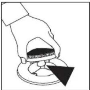
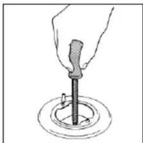
- remove the grids
- remove the covers and the spreaders
- with a 7 mm socket spanner unscrew and remove the injectors.
- replace the injectors with those supplied corresponding to the gas available (see burner and injector characteristics Table)
- replace the various parts proceeding in reverse.
Remember to replace the old rating plate with the new one (supplied).
natural_image
Hand holding a tool above a circular base with a central rod (no text or symbols visible)Whenever the gas pressure used is different (or variable)
from that used, install a pressure regulator which conforms to the local regulations in force on the input pipe.
Instructions forinstallation
Setting the minima
The flame on the small output is regulated in the factory. When the injectors have been replaced or there are special mains pressure conditions, it may be necessary to regulate the minimum again. The operations necessary to perform this operation are the following:
- light the burner
• turn the knob to the minimum position
• take out the knob (and gasket if there is one)
- using a suitably sized screwdriver turn the regulation screw inside or by the side of the tap shaft until a small regular flame is obtained
- put the knob back on and turn it quickly from the maximum position to the minimum position, checking that the flame does not go out
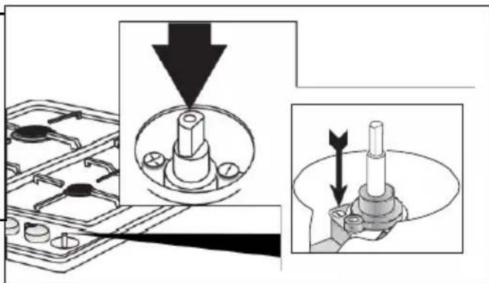
- for burners with safety valve make sure that the regulation obtained is sufficient to maintain heating of the thermocouple. If it is not increase the minimum.
Regulation of minimum for LPG
To regulate the minimum for LPG, completely tighten (clockwise) the screw inside or next to the gas tap pin.
The operations described above can easily be performed whatever the positioning or fastening of the hob to the cabinet.
THE BURNERS REQUIRE NO REGULATION OF THE PRIMARY AIR.
Instructions forinstallation
Burner and nozzle characteristic table
CAT. II 2H3 +
| Burner (heights cover) (mm) | Bypass 1/100 mm | Thermal power (*) (kW) | Liquid gas | Natural gas | |||
| Output (g/h) G30/G31 | Injector 1/100mm | Output (l/h) G20 | Injector 1/100mm | ||||
| Rated | Reduced | ||||||
| Quick (∅ = 100) | 44 | 2,80 | 0,80 | 204/200 | 85 | 264 | 115 |
| Medium quick (∅ = 75) | 34 | 1,70 | 0,60 | 124/121 | 65 | 166 | 97 |
| Auxiliary (∅ = 55) | 29 | 0,95 | 0,40 | 70/68 | 50 | 91 | 72 |
| Triple ring (∅ = 132) | 64 | 3,1 | 1,45 | 226/221 | 90 | 278 | 130 |
| Rated supply pressure (mbar) (1 mbar ≈ 10,197mm H2O) | G30 = 28 - 30 G31 = 37 | G20 = 20 | |||||
| (*) = With dry gas and with greater calorific power (Hs) at 15°C and 1013.26 mbar | |||||||
Instructions forinstallation
Instructions for building in the units
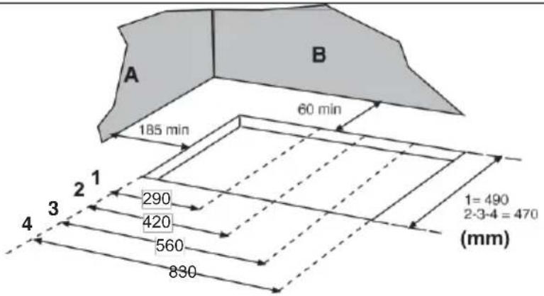
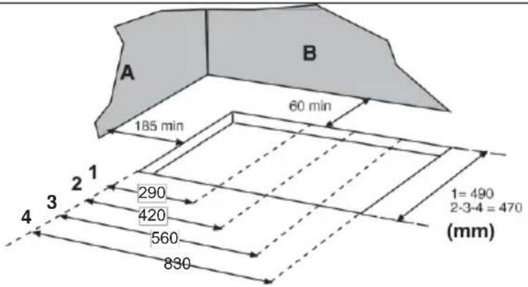
The appliance is of class 3. It can be installed with just one side part (to right or left of the hob) higher than the cooking hob and placed at a minimum distance as shown in figure.
It can be built into all units whose walls withstand a temperature 65^ C higher than room temperature (UNI EN 30-1-1 e/o CEI EN 60335-2-6).
| L(mm) | P(mm) | I(mm) | ||
| hobs series | steel or enameled | glass | ||
| 30 | 320 | 520 | 40 | 40 |
| 45 | 450 | 520 | 40 | 40 |
| 60 | 590 | 520 | 40 | 40 |
| 70 | 680 | 520 | 40 | 40 |
| 90 | 860 | 520 | 40 | 40 |
Hole dimensions
1 = hobs series 30 cm (290x490)
2 = hobs series 45 cm (420x490)
3 = hobs series 60 and 70 cm (560x490)
4 = hobs series 90 cm (830x490)
A = any side wall
B = any back wall
Avoid installing the appliance near inflammable materials (e.g. curtains, cloths, etc.).
The dimensions of the openings for building in are given in the figure which also gives the minimum distances to be respected between the hole for building in and the side and back walls.
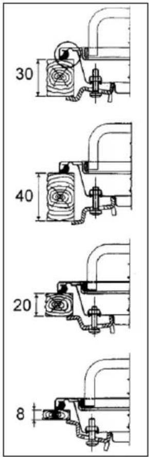
- Position the special sealed gasket (provided) on the edge of the hob making sure that the ends meet without one lying on top of the other.
- Put the hob in the unit opening making sure that it is centred.
- Fasten the hob to the unit with the fastening brackets. The traction of the screws will be enough to cut the sealing gasket so that the excess can easily be removed.
Warnings
If there is a hanging unit over the cooking hob it must be at least 600 mm away from it.
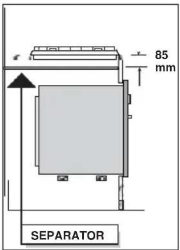
In order to avoid excessive overheating, even if there is no oven below, it is necessary to provide a separating space having at least the size of the embedment hole.
INFINITON
PLACA DE GAS
RÚSTICA
MANUAL DE
USUARIO
MODEL: GAS4RO
SPANISH
- El aparato cumple con las siguientes directivas y regulaciones europeas: Directive 2014/35/EC (Low Voltage Appliances) Directive 2014/30/EC (ElectroMagnetic Compatibility) Directive 2012/19/EC (WEEE - Waste Electrical and Electronic Equipment) Directive 2009/125/EC (ErP - Eco Design) Directive 2011/65/EC (RoHS - restriction of hazardous substances) Regulation 1935/2004/EC (Materials intended to come into contact with food) Regulation 1907/2006/EC (REACH – Restriction of Chemicals) Regulation 2016/426/EC (GAR - Gas Appliances)
natural_image
Mechanical assembly diagram showing a valve and shaft assembly (no text or labels)natural_image
Simple geometric diagram with concentric circles and intersecting lines inside a square frame (no text or symbols)
natural_image
Simple geometric diagram with concentric circles and intersecting lines inside a square frame (no text or symbols)YES
natural_image
Diagram of a satellite or spacecraft with two satellites and a plane intersecting (no text or labels)natural_image
Hand holding a tool above a circular base with a central rod (no text or symbols visible)natural_image
Mechanical assembly diagram showing a bolted component being inserted into a housing, with no visible text or symbols.natural_image
Four identical line drawings of a cooking pot with crossed utensils, arranged horizontally (no text or symbols)Directive 2014/30/EC (ElectroMagnetic Compatibility)
Directive 2012/19/EC (WEEE - Waste Electrical and Electronic Equipment)
Directive 2009/125/EC (ErP - Eco Design)
Directive 2011/65/EC (RoHS - restriction of hazardous substances)
Regulation 1935/2004/EC (Materials intended to come into contact with food
) Regulation 1907/2006/EC (REACH –Restriction of Chemicals)
Regulation 2016/426/EC (GAR - Gas Appliances)
Instruções de uso
natural_image
Mechanical component diagram showing a valve assembly with no visible text or symbolsnatural_image
Simple geometric diagram with concentric circles and intersecting lines inside a square frame (no text or symbols)
natural_image
Simple geometric diagram with concentric circles and intersecting lines inside a square frame (no text or symbols)YES
natural_image
Simple line drawing of a mechanical device with intersecting lines and components (no text or symbols)natural_image
Hand holding a tool above a circular base with a central rod (no text or symbols visible)natural_image
Technical illustration showing mechanical assembly steps with arrows indicating motion (no text or symbols)1 = hobs series 30 cm (290x490)
2 = hobs series 45 cm (420x490)
3 = hobs series 60 and 70 cm (560x490)
4 = hobs series 90 cm (830x490)
A = any side wall
B = any back wall
natural_image
Empty white rectangle with a thin black border (no text or symbols)natural_image
Abstract logo design with stylized 'ME' letters inside a circular arrow pattern (no text or symbols)MEGAEXIT
DISTRIBUIDOR ELECTRO·INFORMÁTICO
MEGAEXIT, S.L.
C/Baza 349, naves 4-6
Polígono Juncaril
18220 ALBOLOTE (Granada)
e-mail: rma@megaexit.com
- TABLE OF CONTENTS
- GENERAL WARNINGS
- Instructions for use:
- Instructions for installation:
- Instructions for use
- Operation of gas burners
- Lighting the burners
- Advice on the use of gas burners
- Operation of electric hot plates
- Advice on use of the hot plates
- Maintenance and cleaning
- Instructions forinstallation
- Positioning
- Gas connection
- ELECTRICAL CONNECTION
- CONNECTION OF THE FEEDING CABLE TO THE MAINS
- Adaptation to different types of gas
- Setting the minima
- Regulation of minimum for LPG
- Burner and nozzle characteristic table
- Instructions for building in the units
- Hole dimensions
- Warnings
- INFINITON
- PLACA DE GAS
- RÚSTICA
- MANUAL DE
- USUARIO
- SPANISH
- Instruções de uso
- MEGAEXIT
- DISTRIBUIDOR ELECTRO·INFORMÁTICO
Brand : Infiniton
Model : GAS4RO
Category : Cooker