
Bragi CinemaScope - Projector Barco - Free user manual and instructions
Find the device manual for free Bragi CinemaScope Barco in PDF.


| Product Type | Video Projector |
| Brand | Barco |
| Model | Bragi CinemaScope |
| Display Technology | Single chip DLP |
| Resolution | 5,120 x 2,160 (5K UHD) |
| Aspect Ratio | 2.37:1 (CinemaScope) |
| Light Source | Solid State RGB LED |
| Light Output | Up to 2,200 ANSI Lumens |
| Contrast Ratio | 1,800:1 Sequential / 450:1 ANSI |
| Light Source Lifetime | Up to 50,000 hours |
| Lens Shift | Up to 122% vertical, up to 40% horizontal |
| Dimensions (W x L x H) | 464 x 679 x 773 mm (excluding lens) |
| Weight | 21.5 kg (excluding lens) |
| Power Consumption | 570 W max |
| Noise Level | 30 - 33 dB(A) typical |
| Operating Temperature | 10°C to 45°C (Sea Level) |
| Inputs | HDMI 2.0, HDBaseT, 2x DVI-D, 2x DisplayPort 1.2, 12G-SDI, RJ45, RS232, USB, DMX |
| Control | IR, RS232, IP, 12v Trigger |
| Image Processing | Embedded Warp & Blend Engine, P7 RealColor |
| Safety Class | Risk Group 2 (RG2) per IEC EN 62471-5 |
| Certifications | CE, FCC Class A, cCSAus |
| Warranty | Limited 3 years parts and labor (extendable to 5 years) |
Frequently Asked Questions - Bragi CinemaScope Barco
User questions about Bragi CinemaScope Barco
0 question about this device. Answer the ones you know or ask your own.
Ask a new question about this device
Download the instructions for your Projector in PDF format for free! Find your manual Bragi CinemaScope - Barco and take your electronic device back in hand. On this page are published all the documents necessary for the use of your device. Bragi CinemaScope by Barco.
USER MANUAL Bragi CinemaScope Barco
natural_image
Black projector with lens and control panel (no visible text or symbols)User Manual
Barco Fredrikstad AS
Registered office: Barco NV
President Kennedypark 35, 8500 Kortrijk, Belgium
Changes
Barco provides this manual 'as is' without warranty of any kind, either expressed or implied, including but not limited to the implied warranties or merchantability and fitness for a particular purpose. Barco may make improvements and/or changes to the product(s) and/or the program(s) described in this publication at any without notice.
This publication could contain technical inaccuracies or typographical errors. Changes are periodically made to the information in this publication; these changes are incorporated in new editions of this publication.
The latest edition of Barco manuals can be downloaded from the Barco web site www.barco.com.
Federal Communications Commission (FCC Statement)
This equipment has been tested and found to comply with the limits for a class A digital device, purses Part 15 of the FCC rules. These limits are designed to provide reasonable protection against harmful interference when the equipment is operated in a commercial environment. This equipment generates, use and can radiate radio frequency energy and, if not installed and used in accordance with the instruction manual, may cause harmful interference to radio communications. Operation of this equipment in a residential area may cause harmful interference, in which case the user will be responsible for correcting any interest at his own expense
Changes or modifications not expressly approved by the party responsible for compliance could void the user's authority to operate the equipment
FCC responsible: Barco Inc.
3059 Premiere Parkway Suite 400
30097 Duluth GA, United States
Tel: +1 678 475 8000
Trademarks
Brand and product names mentioned in this manual may be trademarks, registered trademarks or copyright of their respective holders. All brand and product names mentioned in this manual serve as comments examples and are not to be understood as advertising for the products or their manufacturers.
Turkey RoHS compliance

[Republic of Turkey: In conformity with the WEEE Regulation]
Disposal Information

Waste Electrical and Electronic Equipment (WEEE)
This symbol on the product indicates that, under the European Directive 2012/19/EU governing waste from electrical and electronic equipment, this product must not be disposed of with other municipal waste. Please dispose of your waste equipment by handing it over to a designated collection point for the recycling of waste electrical and electronic equipment. To prevent possibl harm to the environment or human health from uncontrolled waste disposal, please separate the items from other types of waste and recycle them responsibly to promote the sustainable reuse material resources.
For more information about recycling of this product, please contact your local city office or yc municipal waste disposal service. For details, please visit the Barco website at: https://www.barco.com/about/sustainability/waste-of-electronic-equipment-customers
Disposal of batteries in the product

This product contains batteries covered by the Directive 2006/66/EC which must be collected and disposed of separately from municipal waste.
If the battery contains more than the specified values of lead (Pb), mercury (Hg) or cadmium these chemical symbols will appear below the crossed-out wheeled bin symbol.
By participating in separate collection of batteries, you will help to ensure proper disposal and prevent potential negative effects on the environment and human health.
Guarantee and Compensation
Barco provides a guarantee relating to perfect manufacturing as part of the legally stipulated terms of guarantee. On receipt, the purchaser must immediately inspect all delivered goods for damage incurred or transport, as well as for material and manufacturing faults Barco must be informed immediately in writing any complaints.
The period of guarantee begins on the date of transfer of risks, in the case of special systems and the date of commissioning, at latest 30 days after the transfer of risks. In the event of justified notice complaint, Barco can repair the fault or provide a replacement at its own discretion within an appropriate period. If this measure proves to be impossible or unsuccessful, the purchaser can demand a reduction in purchase price or cancellation of the contract. All other claims, in particular those relating to compensatory direct or indirect damage, and also damage attributed to the operation of software as well as to other provided by Barco, being a component of the system or independent service, will be deemed invalid prior to the damage is not proven to be attributed to the absence of properties guaranteed in writing or due to intent or gross negligence or part of Barco.
If the purchaser or a third party carries out modifications or repairs on goods delivered by Barco, or if goods are handled incorrectly, in particular if the systems are operated incorrectly or if, after the transfer risks, the goods are subject to influences not agreed upon in the contract, all guarantee claims of the purchaser will be rendered invalid. Not included in the guarantee coverage are system failures which are attributed to programs or special electronic circuitry provided by the purchaser, e.g. interfaces. Normal was as well as normal maintenance are not subject to the guarantee provided by Barco either.
The environmental conditions as well as the servicing and maintenance regulations specified in this man must be complied with by the customer.
Copyright ©
All rights reserved. No part of this document may be copied, reproduced or translated. It shall not other recorded, transmitted or stored in a retrieval system without the prior written consent of Barco.
Software License Agreement
Carefully read the following terms and conditions before using this software. Any use of this software in the acceptance of this license agreement and warranty.
Terms and Conditions:
-
No redistribution of the software is allowed.
-
Reverse-Engineering. This software product may not be reverse engineered, decompiled, disassembled altered.
Disclaimer of Warranty:
This software and the accompanying files are sold “as is” and without warranties as to performance or merchantability or any other warranties whether expressed or implied. In no event shall Barco be liable damage of any kind, loss of data, loss of profits, business interruption or other pecuniary loss arising indirectly. Any liability of the seller will be exclusively limited to replacement of the product or refund of purchase price.
Table of contents
1 Safety 7
1.1 General considerations 8
1.2 Important safety instructions.... 10
1.3 Product safety labels....13
1.4 Compliance 14
2 Getting started 15
2.1 Projector orientation 16
2.2 Projector components 17
3 Local keypad 19
3.1 Local keypad functions 20
3.2 Local keypad backlight 21
3.3 LCD touch panel....22
4 Basic Remote Control Unit 23
4.1 Basic remote functions 24
4.2 Basic remote batteries 25
5 Pulse Remote Control Unit 27
5.1 Pulse RCU functions 28
5.2 Pulse RCU battery installation....29
5.3 Pulse RCU on/off button 31
5.4 Pulse RCU "button pressed indicator" 32
5.5 Pulse RCU "RGB filter" button 33
5.6 Pulse RCU "Projector OSD on/off" button....34
5.7 Using the XLR connector of the RCU 35
5.8 Using the mini-jack connector of the RCU 36
5.9 Pulse RCU silicone protection sleeve (optional) 37
6 Powering On/Off 39
6.1 Power modes 40
6.2 Power up the projector 41
6.3 Power Off the projector....42
6.4 Power mode transitions....43
6.5 Increasing the projector lifetime....45
6.6 Operation in 24/7 Mode....46
7 Controlling the projector 47
7.1 Using the RCU....48
7.2 Displaying and Programming addresses into the RCU 49
7.3 Setting the projector addresses....50
7.4 Quick setup via Direct access 51
7.5 Shortcut buttons....52
8 Input & Communication 53
8.1 Connector panel 54
8.2 Power on / Standby button backlight indications....55
8.3 Input source connections 56
8.4 Control Interfaces 57
8.4.1 RS-232 57
8.4.2 LAN/Ethernet 57
8.4.3 USB-A port....57
9 Maintenance....59
9.1 Software update....60
9.2 Projector lenses 62
9.3 Projector cabinet 63
9.4 Filters 64
A Specifications 65
A.1 Specifications Bragi....66
A.2 Specifications Bragi CinemaScope 69
A.3 Specifications DVI-I inputs....72
A.4 Display Port 1.2....73
A.5 Specifications HDMI 2.0....74
A.6 Specifications HDBase T input....75
B Regulatory information....77
B.1 Contact information....78
B.2 Production address....79
B.3 Product compliance EU 80
B.4 Product compliance UK....81
B.5 Product compliance US....82
B.6 Product compliance Turkey 83
B.7 Product compliance EAC 84
B.8 Product compliance China 85
B.9 Product compliance Taiwan 87
B.10 Trademark notice 89
B.11 Product privacy statement....90
C DMX chart....91
C.1 DMX chart, Basic 92
C.2 DMX chart, Extended....93
Glossary 95
List of tools 97
Index 99
Safety 1
1.1 General considerations....8
1.2 Important safety instructions....10
1.3 Product safety labels....13
1.4 Compliance....14
About this document
Read this document attentively. It contains important information to prevent personal injury while installing using the Bragi product. Furthermore, it includes several cautions to prevent damage to the unit. Ensure all safety guidelines, safety instructions and warnings mentioned in this chapter are understood and follow before installing the Bragi product.
Clarification of the term "Bragi" used in this document
When referring in this document to the term “Bragi” means that the content is applicable for following products:
- Bragi
Model certification name
• GPC

Barco provides a guarantee relating to perfect manufacturing as part of the legally stipulated term of guarantee. Observing the specification mentioned in this chapter is critical for optimal performance. Neglecting this can result in loss of warranty.
1.1 General considerations

WARNING: Be aware of suspended loads.

WARNING: When suspending loads, wear a hard hat to reduce the risk of personal injury.

WARNING: Be careful while working with heavy loads.

WARNING: Mind your fingers while working with heavy loads.

WARNING: In case of emergency, disconnect the device from the mains power supply. In case power input at the projector side is not accessible, a readily accessible general disconnect device shall be incorporated.
General safety instructions
• Before operating this equipment please read this manual thoroughly and retain it for future reference.
- All warnings on the unit and in its documentation manuals must be adhered to.
• Installation and preliminary adjustments must be performed by qualified Barco personnel or by authorized Barco service dealers.
- This product contains no user serviceable parts. Attempts to modify/replace mechanics or electronics inside the housing or compartments will violate any warranties and may be hazardous.
- All instructions for operating and use of this equipment must be followed precisely.
- All local installation codes must be adhered to.
Notice on safety
This equipment is built in accordance with the requirements of the applicable international safety standard. These safety standards impose important requirements on the use of safety critical components, materials and insulation, in order to protect the user or operator against risk of electric shock and energy hazard having access to live parts. Safety standards also impose limits to the internal and external temperature radiation levels, mechanical stability and strength, enclosure construction and protection against the risk of fire. Simulated single fault condition testing ensures the safety of the equipment to the user even when equipment's normal operation fails.
Optical radiation safety precautions
- Do not stare into Beam.
• This projector is Risk Group 2 (RG2) according to IEC EN 62471-5. - Any operation or adjustment not specifically instructed by the user's guide creates the risk of hazardous light radiation exposure.
- Do not open or disassemble the projector as this may cause danger to unauthorized personnel.
• Additional RG2 warning against eye exposure for close exposures less than 1m. WARNING: MOUNT ABOVE THE HEADS OF CHILDREN.
Users definition
These projectors are intended "FOR PROFESSIONAL USE ONLY", this means installation can only be carried out by trained and authorized persons.
Throughout this manual, the terms SERVICE PERSONNEL, INSTALLER refers to persons having appropriate technical training and experience necessary to be knowledgeable of potential hazards to which they are exposed (including, but not limited to HIGH VOLTAGE ELECTRIC and ELECTRONIC CIRCUITRY, HIGH TEMPERATURES and HIGH BRIGHTNESS SOURCES) in performing a task, and of measures to minimis the potential risks to themselves or other persons.
The term USER or OPERATOR of RG2 projectors refers to any other person than SERVICE PERSONN INSTALLER. The term USER or OPERATOR of RG3 projectors refers to any person trained and author operate professional RG3 projectors. The USER or OPERATOR may only perform the maintenance tasks forth in the user manual or the maintenance tasks for which they are trained and authorized. All other maintenance tasks and service tasks must be performed by qualified SERVICE PERSONNEL.
1.2 Important safety instructions
To prevent the risk of electrical shock
- This product should be operated from a mono phase AC power source. Ensure that the mains voltage capacity match the projectors electrical ratings. If you are unable to install the AC requirements, carry your electrician. Do not defeat the purpose of grounding.
- This apparatus must be grounded (earthed) via the supplied 3 conductor AC power cable. If none of supplied power cables are the correct one, consult your dealer.
- Do not allow anything to rest on the power cord. Do not locate this product where persons will wait cord. To disconnect the cord, pull it out by the plug. Never pull the cord itself.
- Do not operate the projector with a damaged cord. Replace the cord.
- Do not operate the projector if the projector has been dropped or damaged - until it has been exa and approved for operation by a qualified service technician.
- Position the cord so that it will not be tripped over, pulled, or contact hot surfaces.
- If an extension cord is necessary, a cord with a current rating at least equal to that of the project be used. A cord rated for less amperage than the projector may overheat.
- Do not expose this projector to rain or moisture.
- Do not immerse or expose this projector in water or other liquids.
- Do not spill liquid of any kind on this projector.
- Should any liquid or solid object fall into the cabinet, unplug the set and have it checked by qualified service personnel before resuming operations.
- Do not disassemble this projector, always take it to an authorized trained service person when servic repair work is required.
- Do not use an accessory attachment which is not recommended by the manufacturer.
- Lightning - For added protection for this video product during a lightning storm, or when it is left u and unused for long periods of time, unplug it from the wall outlet. This will prevent damage to th due to lightning and AC power-line surges.
- Never push objects of any kind into this product through cabinet slots as they may touch dangerous voltage points or short out parts that could result in a risk of fire or electrical shock.
- If you are unable to insert the plug into the outlet, contact your electrician to replace your obsolete Do not defeat the purpose of the grounding-type plug.
- Ensure that the main power cord complies with the national regulations at the site where the equipment used.
- Do not use unauthorized replacements.
- Make sure that no objects enter into the vents and openings of the set.
- The projector is designed for indoor use only. Never operate the unit outdoors.
To prevent personal injury
- To prevent injury and physical damage, always read this manual and all labels on the system before connecting to the wall outlet or adjusting the projector.
• To prevent injury, take note of the weight of the projector.
• To prevent injury, ensure that the lens and all covers are correctly installed. See installation procedure - Warning: high intensity light beam. NEVER look into the lens! High luminance could result in damage eye.
- Always switch off the projector and disconnect from the mains power supply before attempting to rem any of the projector covers or access parts inside the projector.
- This product contains no user serviceable parts. Attempts to modify/replace mechanics or electronics inside the housing or compartments will violate any warranties and may be hazardous.
- Do not place this equipment on an unstable cart, stand, or table. The product may fall, causing ser damage to it and possible injury to the user.
- Only place the projector on a stable surface, or mount it securely using an approved ceiling-mount.
To prevent fire hazard
- Barco projection products are designed and manufactured to meet the most stringent safety regulations. This projector radiates heat on its external surfaces and from ventilation ducts during normal operation which is both normal and safe. Exposing flammable or combustible materials into close proximity of a projector could result in the spontaneous ignition of that material, resulting in a fire. For this reason,
absolutely necessary to leave an “exclusion zone” around all external surfaces of the projector wherein flammable or combustible materials are present.
- Do not place flammable or combustible materials near the projector!
- Caution! Hot air is exhausted from the rear vent. Do not place objects that are sensitive to heat net 25 cm (10") to the exhaust vent.
- Slots and openings in this equipment are provided for ventilation. To ensure reliable operation of the projector and to protect it from overheating, these openings must not be blocked or covered.
- The openings should never be blocked by placing the projector too close to walls, or other similar s Allow for sufficient distance to walls and ceilings to avoid overheating. Minimum safety distance to the exhaust area of the unit must not be less than 25 cm (10") and to the intake area, not less than
- This projector should never be placed near or over a radiator or heat register.
- This projector should not be placed in a built-in installation or enclosure unless proper ventilation is provided.
- Do not cover the projector or the lens with any material while the projector is in operation. Keep fl and combustible materials away from the projector at all times.
- Mount the projector in a well-ventilated area away from sources of ignition and out of direct sun light. Always allow ample airflow through the projector.
- Never expose the projector to rain or moisture. In the event of fire _2 or dry sand, fire extinguishers.
- Never use water on an electrical fire.
- Always have service performed on this projector by qualified service personnel. Always insist on genui Barco replacement parts. Never use non-Barco replacement parts as they may degrade the safety of projector.
- Projection rooms must be well ventilated or cooled in order to avoid heat buildup.
- Let the projector cool down completely before storing. Remove cord from the projector when storing.
To prevent battery explosion
- Danger of explosion if battery is incorrectly installed.
- Replace only with the same or equivalent type recommended by the manufacturer.
- For disposal of used batteries, always consult federal, state, local and provincial hazardous waste disp rules and regulations to ensure proper disposal.
To prevent projector damage
- To ensure correct airflow is maintained, the projector should only be operated when all of its covers place. The exception from this is the front cover, that can be removed to give access to multiple points. See User Guide for more detailed info regarding this issue.
- Always remove lens cap before switching on the projector. If the lens cap is not removed, it may be to the high energy light emitted through the lens. Melting the lens cap may permanently damage the surface of the projection lens.
- Only connect the projector to signal sources and voltages as described in the technical specification. Connecting to unspecified signal sources or voltages may lead to malfunction and permanent damage the unit.
• To ensure correct airflow is maintained, it should only be operated when all of its covers are in pla - The projector must always be installed in a manner which ensures free flow of air into its air inlets unimpeded evacuation of the hot air from its cooling system.
- Slots and openings in the cabinet are provided for ventilation. To ensure reliable operation of the product and to protect it from overheating, these openings must not be blocked or covered. The openings are never be blocked by placing the product on a bed, sofa, rug, or other similar surface. This product is never be placed near or over a radiator or heat register. The device should not be placed in a b installation or enclosure unless proper ventilation is provided. Ensure that nothing can be spilled on, dropped inside the projector. If this does happen, switch off and unplug the mains supply immediately not operate the projector again until it has been checked by Barco authorized service personnel.
- Do not block the projector cooling fans or free air movement around the projector. Minimum safety c to the exhaust area of the unit must not be less than 25 cm (10") and to the intake area, not I cm (10").
- Do not use this equipment near water.
-
Do not operate the projector outside its temperature and humidity specifications as this may result in overheating and malfunction.
-
Never place the projector in direct sun light. Sun light on the lens can severely damage the Digital Devices™ in which case there is a loss of warranty.
- Save the original shipping carton and packing material. They will come in handy if you ever have to your equipment. For maximum protection, repack your set as it was originally packed at the factory.
- Unplug this product from the wall outlet before cleaning. Do not use liquid cleaners or aerosol clean. Use a damp cloth for cleaning. Never use strong solvents, such as thinner or benzine, or abrasive cleaners, since these will damage the cabinet. Stubborn stains may be removed with a cloth lightly dampened with mild detergent solution.
- To ensure the highest optical performance and resolution, the projection lenses are specially treated with an anti-reflective coating, therefore, avoid touching the lens. To remove dust on the lens, use a soft cloth. Do not use a damp cloth, detergent solution, or thinner.
On servicing
- Do not attempt to service this product yourself, as opening or removing covers may expose you to dangerous voltage potentials and risk of electric shock.
• Refer all servicing to qualified service personnel. - Attempts to alter the factory-set internal controls or to change other control settings not specially disc in this manual can lead to permanent damage to the unit and cancellation of the warranty.
- Replacement parts: When replacement parts are required, be sure the service technician has used ori Barco replacement parts or authorized replacement parts which have the same characteristics as the Barco original part. Unauthorized substitutions may result in degraded performance and reliability, fire, electric shock or other hazards. Unauthorized substitutions may void warranty.
- Safety check: Upon completion of any service or repairs to this unit, ask the service technician to p safety checks to determine that the product is in proper operating condition.
Malfunction unit
Remove all power from the product and refer servicing to qualified service technicians under the following conditions:
- When the power cord or plug is damaged or frayed.
- If liquid has been spilled into the equipment.
- If the product has been exposed to rain or water.
- If the product does not operate normally when the operating instructions are followed. Adjust only the controls that are covered by the operating instructions since improper adjustment of the other controls result in damage and will often require extensive work by a qualified technician to restore the product normal operation.
- If the product has been dropped or the cabinet has been damaged.
• If the product exhibits a distinct change in performance, indicating a need for service.
Safety Data Sheets for Hazardous Chemicals
For safe handling information on chemical products, consult the Safety Data Sheet (SDS). SDSs are av upon request via safetydatasheets@barco.com.
1.3 Product safety labels
Light beam related safety labels
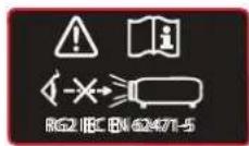
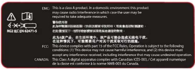
Safety labels explanation:
Refer to user manual for further information!


Caution! Do not stare into beam, RG2 product.

No telephone! Do not connect to telephone lines.

RG2 Label
EMC Label
Location of safety label
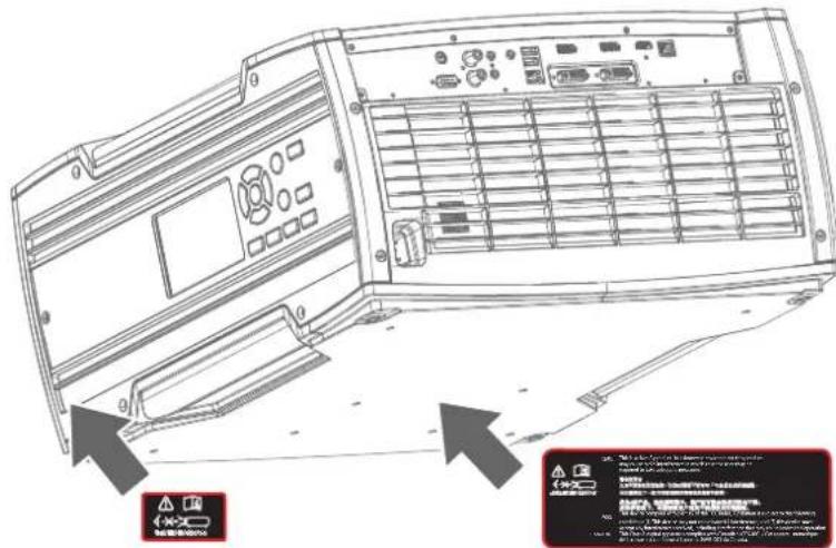
Image 1-1 Location of RG2 and EMC label.
1.4 Compliance
UK Compliance

This product is fit for use in the UK.
Authorised Representative: Barco UK Ltd
Address: Building 329, Doncastle Road
Bracknell RG12 8PE, Berkshire, United Kingdom
Getting started 2
2.1 Projector orientation
Projector orientation
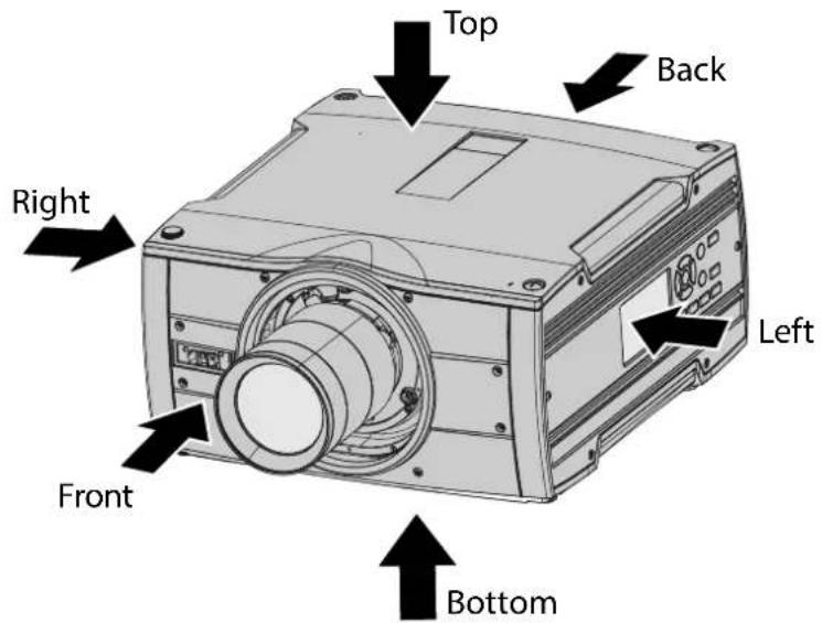
Image 2-1
2.2 Projector components
Main Components
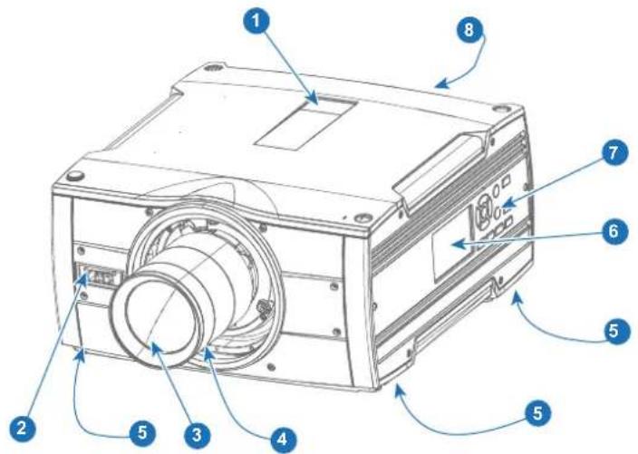
Image 2-2
1 IR receiver top
2 IR receiver front
3 Lens
4 Lens release handle
5 Projector feet (x4)
6 LCD Panel
7 Local keypad
8 Back panel and connectors
Local keypad 3
3.1 Local keypad functions....20
3.2 Local keypad backlight....21
3.3 LCD touch panel....22
3.1 Local keypad functions
Keypad overview
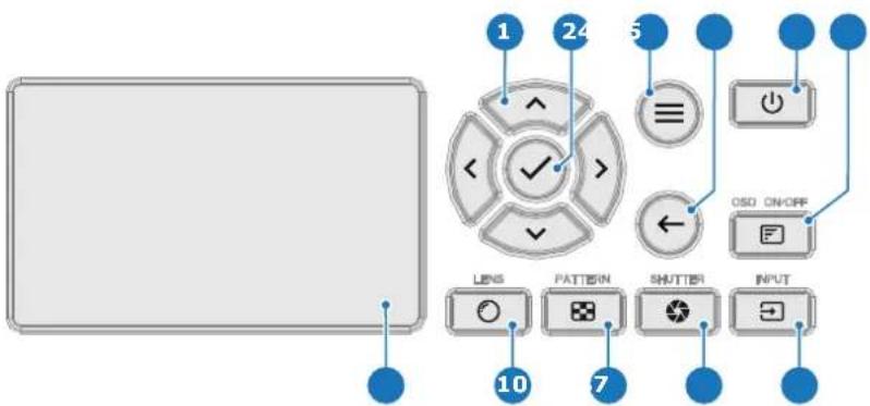
Image 3-1
1 Menu navigation
2 Menu confirmation, OK button
3 Menu open / close
4 Menu back
5 Power on / off
6 Projector OSD on / off
7 Input selection
8 Shutter open / close
9 Test patterns
10 Lens adjustment
11 LCD touch panel
Functionality
The local keypad gives direct access to several functions, in addition, access to the Pulse menu system. The local keypad has a backlight that can be switched on and off manually. By default the light turns minutes.

Refer to the Pulse OSD user guide for detailed guidance on all software features of the projector.

The Pulse software has regular new releases due to continuous improvements. Hence, OSD user guide is subject to updates. Download the latest version of the user guide from the Barco website using following link: https://www.barco.com/support.
the Pulse
3.2 Local keypad backlight
Button backlight status
The Power and Shutter buttons are equipped with white, blue and red backlit LEDs. The other keys are only equipped with white and blue backlit LEDs. The LEDs are controlled according to the features available
Button Color status
Description
Power button  | Blinking WHITE (slow) Projector starts up (booting) |
| Blinking WHITE (fast) Firmware update | |
| Solid WHITE Projector is in Standby mode | |
| Blinking BLUE Projector goes to ON mode | |
| Solid BLUE Projector is ON | |
| Blinking RED Error condition | |
Shutter button  | Off (no color) Projector is OFF, starts up, or is in (ECO) Standby. |
| Solid WHITE Projector is ON, shutter is open | |
| Solid RED Projector is ON, shutter is closed |
3.3 LCD touch panel
Functionality
The LCD touch panel has two main functions:
- Showing the menus, adjustment information and if enabled a mirror of the OSD (On Screen Display
-
Information regarding the status of the projector:
-
Projector status
- Network address
• Active source - Current firmware version
- Operation Data
• Active functions (Enabled Functions).
Toggle between the two main function by using the Menu button on the local keypad, or on the remote control unit.
The LCD touch panel will fade out 30 seconds after the last key operation.

Refer to the Pulse OSD user guide for detailed guidance on all software features of the projector.
Navigation
Use the arrow keys on the local keypad or on the remote control unit to navigate through the menus LCD touch panel.
In addition to the remote control unit and the local keypad, it is also possible to navigate in the mer touch functionality in the LCD panel:
- Press the icons to select the functions.
- Select switches to toggle.
- Select and drag sliders to adjust slider value.

The LCD menus can occasionally be slightly different in layout compared with the OSD menu, to a more optimal layout regarding to the touch functionality of the LCD.
Basic Remote Control Unit
4
4.1 Basic remote functions....24
4.2 Basic remote batteries 25
About the basic remote
The Bragi projector is standard delivered with a basic remote control unit (without batteries). While this control unit has a more limited amount of available features compared with the optional Pulse RCU, it able to help you out with basic controls.

For more information about the optional Pulse RCU see chapter "Pulse Remote Control Unit", p 27. For ordering information see Barco website.
4.1 Basic remote functions
Functions
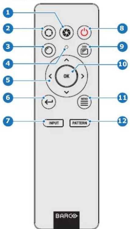
Image 4-1
1 Close shutter
2 Open shutter
3 Open Lens menu
4 Button pressed indicator
5 Menu navigation keys
6 Move back one level in menu system
7 Open Source menu
8 Power on / off
9 OSD menu on / off
10 Menu confirmation
11 GUI activate / deactivate
12 Open Test pattern menu

The Power on / off button only shifts power between Ready and ON mode.

When pressing the GUI activate / deactivate button while the projector is in stand-by power up the projector.
mode, wil
4.2 Basic remote batteries
Battery placement & replacement
The basic remote control is powered by two (2) standard AAA batteries. The needed batteries are not in the packaging.
The battery compartment is on the back side of the basic remote control. The following image illustrates to open the battery compartment.

natural_image
Diagram showing two battery cells with positive and negative charges, connected by a red double-headed arrow (no text or symbols)Image 4-2 Position of batteries in basic remote.

CAUTION: Replace batteries with the correct battery type. Only use AAA size batteries. There is a risk of explosion if the battery is replaced with an incorrect type.
Make sure the polarities match the + and - marks, as depicted on the inside of the battery compartment. There is a risk of explosion if the batteries are installed incorrectly.
Pulse Remote Control Unit
5
5.1 Pulse RCU functions....28
5.2 Pulse RCU battery installation 29
5.3 Pulse RCU on/off button....31
5.4 Pulse RCU "button pressed indicator" 32
5.5 Pulse RCU "RGB filter" button 33
5.6 Pulse RCU "Projector OSD on/off" button 34
5.7 Using the XLR connector of the RCU 35
5.8 Using the mini-jack connector of the RCU 36
5.9 Pulse RCU silicone protection sleeve (optional) 37
5.1 Pulse RCU functions
Functions
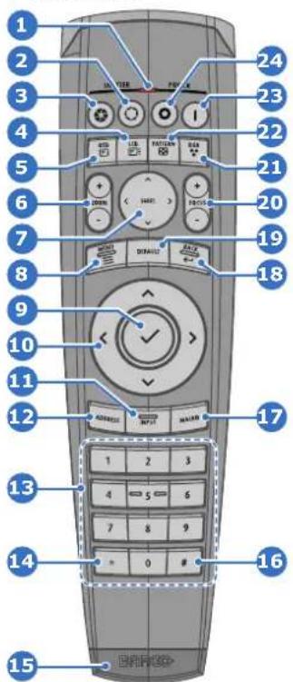
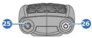
Image 5-1
1 Button pressed indicator
2 Shutter open
3 Shutter close
4 LCD/Touch panel on / off
5 Projector OSD on / off
6 Lens zoom
7 Lens shift
8 Menu open / close
9 Menu selection, OK button
10 Menu navigation
11 Input selection
12 Address button
13 Numeric buttons
14 Backspace (while entering values)
15 XLR connector
16 Decimal mark (while entering values)
17 Macro button (Not in use)
18 Menu back
19 Default value button
20 Lens focus
21 RGB filter
22 Test patterns
23 Power on
24 Power off
25 3.5 mm jack
26 RCU on / off
5.2 Pulse RCU battery installation
About the batteries for the remote control

Batteries are no longer included in the packaging. It is up to the user to purchase batteries.
Use 2 AA size (alkaline) batteries in the remote control.
the correct
Before using your remote control, first install the batteries.
How to install
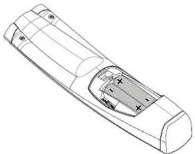
- Push the battery cover tab with the fingernail a little backwards (1) and pull, at the same time, the cover upwards (2).
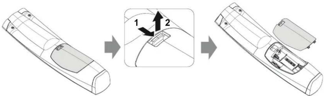
Image 5-2
- Insert the two AA size batteries, making sure the polarities match the + and - marks inside the battery compartment.

Tip: Use alkaline batteries for optimum range and lifetime.
natural_image
Technical line drawing of a remote control casing with visible battery compartment (no text or symbols)Image 5-3
- Insert (1) both lower tabs of the battery cover in the gaps at the bottom of the remote control, and press (2) the cover until it clicks in place.
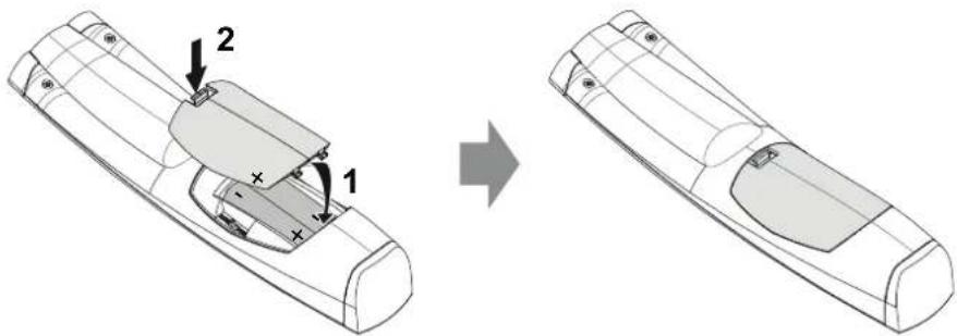
Image 5-4

When replacing batteries, the broadcast address of the RCU will be reset to its default value '

CAUTION: Replace with the correct battery type. Use two AA size batteries. There is a risk of explosion if the battery is replaced with an incorrect type.

CAUTION: Replace the battery as explained above. There is a risk of explosion if the battery incorrectly installed.
5.3 Pulse RCU on/off button
Function of the remote control on/off button
The Pulse remote control unit has at the front side an on/off button (reference 1 Image 5–5). Switching off the remote control prevents that unwanted commands are send due to an accidental key press. Furthermore switching the RCU off will extend the battery lifetime of the remote control.
To activate the remote control, press the on/off button until the button pressed indicator will turn off (3 seconds).
To deactivate the remote control, press the on/off button again.
Default after (re)placing batteries, is "ON".
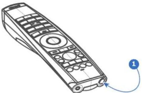
natural_image
Line drawing of a remote control with labeled button and cable (no text or symbols on device)Image 5-5
5.4 Pulse RCU "button pressed indicator"
Functions button pressed indicator
- Rapidly flashes when commands are sent, this is the normal "button pressed" indication.
• 1 Short flash when remote control is switched ON by means of the on/off button.
• Continuously lit (up to 5 seconds) when address digits are expected after pressing the ADDR button. - Slowly flashes (2 times a second) when the battery level is becoming low; typically when more than the useful life is past.
5.5 Pulse RCU "RGB filter" button
Filtering the color of the projected image
By pressing the RGB filter button on the RCU you can place a color filter on the output of the project feature can be useful during the installation and configuration of a multi-projector or multi-channel setup. having one projector project a red image and another project a green image, it is easier to spot and overlap section.
By pressing this button multiple times, you will have different active filters, in the following cycle:
• Red + Green + Blue (default)
- Red only
- Green only
- Blue only
- Red + Green
- Green + Blue
- Red + Blue
- Red + Green + Blue
- etc

After powering up, the colors will always revert back to full RGB.
5.6 Pulse RCU "Projector OSD on/off" button
Functions Projector on/off button
While the light source is on, you can toggle on and off the projection of the On-screen display by projector OSD on/off button.
From Pulse 2.3 onward, this button now supports another function. If “Stealth mode” has been configured for the LCD display, pressing this button a long time (5 seconds or more) will activate or deactivate Steal For more info on Stealth mode, see Pulse software user guide.
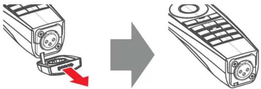
5.7 Using the XLR connector of the RCU

Connecting a cable with the XLR connector will reset the broadcast address of the RCU to its value '0'.
Revised RCU
Revised Remote Control Units produced from April 2023 onward will require the projector to run softwar (or newer) in order to properly use the XLR connector. If not yet updated to the most recent version, the projector software. For more information, see "Software update", page 60.
How to use the XLR connector
- Remove the XLR cover by pulling it backwards.
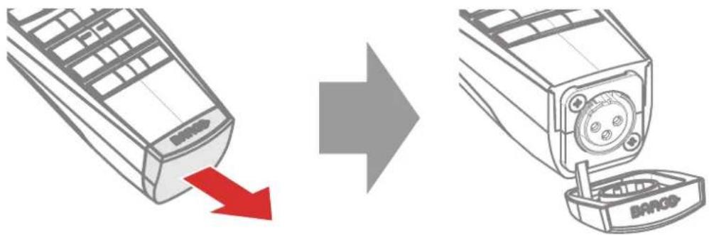
Image 5–6
- Connect a cable with XLR plug into the XLR connector of the RCU.
- Connect the other end of the cable with the XLR input of the projector.
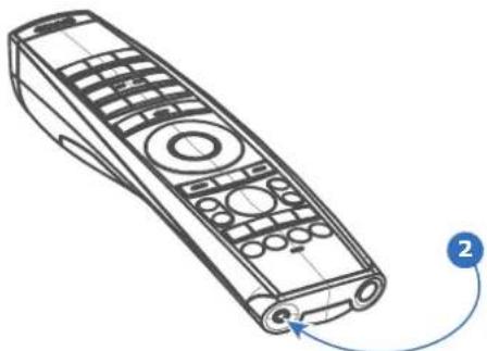
5.8 Using the mini-jack connector of the RCU

Connecting a cable with the mini-jack connector will reset the broadcast address of the RCU to default value '0'.
How to use the mini-jack connector
-
Connect a cable with the mini-jack connector (reference 2 Image 5-7) of the RCU.
-
Connect the other end of the cable with the mini-jack input of the projector.
natural_image
Line drawing of a remote control device with buttons and a blue arrow indicating rotation (no text or symbols)Image 5–7

Note: While the mini-jack cable is connected, the IR receivers of the projector are switched off.
5.9 Pulse RCU silicone protection sleeve (optional)
Introduction
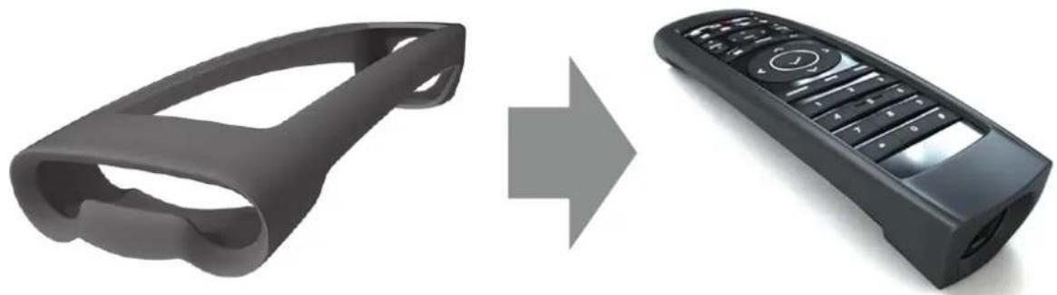
Barco offers a silicone form fitting protection sleeve for the Pulse RCU. The silicone material keeps it comfortably, non slip and soft touch. All buttons and openings remain accessible. The sleeve is quick as easy installed. For ordering information see Barco website.
How to install
- Pull off the rubber XLR-lid from the RCU.
natural_image
Diagram showing a mobile phone with a red arrow indicating a drop, before and after the next image (no text or symbols present)Image 5-8
- Place back side (XLR side) of the RCU into the sleeve and pull the other side of the sleeve over the front side of the RCU.
natural_image
Two 3D models: a remote control with a handle and a black remote control with a keypad, both shown in transformation from left to right (no text or symbols)Image 5–9
Powering On/Off
6
6.1 Power modes....40
6.2 Power up the projector 41
6.3 Power Off the projector 42
6.4 Power mode transitions....43
6.5 Increasing the projector lifetime 45
6.6 Operation in 24/7 Mode....46
6.1 Power modes
General
The table below details the Medea power modes.
Mode
Description
| ON (normal) Projector is booted up and the light source is on |
| READY Projector is booted up but the light source is off |
| ECO (Standby) Light source is switched off and projector electronics are powered down |

Energy consumption is significantly lowers in ECO (Standby) mode: only <0.5W if network is no plugged in and 2W with network (Wake-on-LAN).

In ECO (Standby) mode, remote power up (Wake-on-LAN) and local power up (button) are supported.

Wake-On-LAN (WOL)
The link speed of the projector network interface in ECO mode is reduced to 10Mbit/s. This is standard practice in the industry to not waste power. Hence, the network connected with the projector must support such a low link speed to enable the remote wake up of the projector. implies that all peripherals (switchers, routers...) in the network path must support WOL and configured correctly to support WOL.
6.2 Power up the projector

CAUTION: Sources should always be connected before the projector is powered up

CAUTION: Ensure that the main power cord complies with the national regulations where the equipment is used.
Do not use unauthorized replacements.
Do not use power cords which are damaged.
Power up the projector using the keypad or remote
-
Plug the mains cord into the projector.
-
Plug the mains cord into a grounded AC outlet.
The projector starts up to READY mode as soon as the projector is connected with power net. The Power on/off button will blink until Ready mode is achieved. Once in Ready mode, the Power on/off button will be lit WHITE. The start up screen is displayed on the touch panel. Once the startup is completed, the status screen will be displayed.

- Press the power button on the keypad or the power button on the remote.
The projector will continue to ON mode. The Power on/off button will blink until the projector is ready for projection. Once the projector is fully started up, the Power on/off button will be lit BLUE.

flowchart
graph LR
    A["Power Icon"] --> B["Power Icon"]
    B --> C["Power Icon"]
Image 6-2
- When the power button backlight is solid blue, the projector is ready for use.
6.3 Power Off the projector
How to power off the projector
- Use the standby button, or the Power On button on the remote control, to switch off the projector.
The projector will switch to READY mode first in order to run through a cool down phase.
- If ECO Standby mode is enabled in the service menu (refer to the section "GUI - system settings/Standby ECO", in User Guide) the projector will automatically go to ECO standby mode after a time-out (default 15 minutes).

Some actions like apply a grey test pattern are done during the two minutes of the cool down in order to minimize the potential effect of burn-in and increase the projector lifetime.

CAUTION: Never switch off the projector by means of unplugging mains cord or by cut down mains power.

Barco advises to keep the projector always powered and use the ECO mode for low power consumption.
How to unplug the projector
- Follow the procedure above to Switch Off the projector.
- Wait at least 2 minutes prior to unplug the projector by removing the power cord from the AC outlet.

CAUTION: It is very important to wait few minutes before unplugging the power cord. If the co-down phase is not adhered, projector lifetime could be degraded.
6.4 Power mode transitions
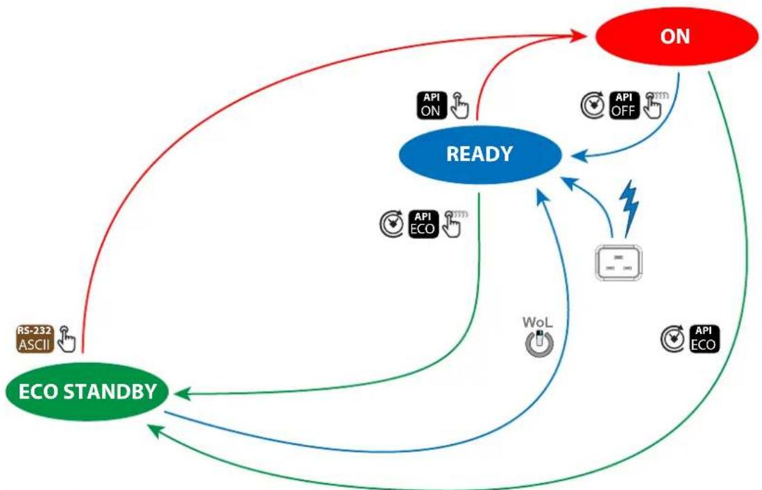
Transition diagram
This diagram shows all modes available on the projector (ON, READY, ECO STANDBY), and the action necessary to change mode.
flowchart
graph TD
    A["READY"] -->|API ON| B["ON"]
    A -->|API OFF| C["API ECO"]
    A -->|API ECO| D["RS-232 ASCII"]
    A -->|API ECO| E["API ECO"]
    A --> F["WoL"]
    F --> A
    A --> G["ECO STANDBY"]
    G --> A
    style A fill:#6699CC,stroke:#333
    style B fill:#FFD700,stroke:#333
    style C fill:#FFD700,stroke:#333
    style D fill:#FFD700,stroke:#333
    style E fill:#FFD700,stroke:#333
    style F fill:#FFD700,stroke:#333
    style G fill:#FFD700,stroke:#333
Image 6-3
| Symbol | Description |
| Short pressing the Power on/off button on the local keypad or on the control unit. | |
| Long pressing the Power on/off button on the local keypad or on the control unit. | |
| Wake-On-LAN (WOL). Only works if a network was connected with the the projector while the projector went to ECO STANDBY. | |
| API ON API OFF API ECO | API command to change the power state of the projector (Power ON, Go to ECO). See Pulse user guide for more info (E.g. PJLink). |
| RS-232 ASCII | RS-232 ASCII command to Power ON the projector when in ECO STANDBY. |
| Auto light source off and auto standby features. Default disabled (factory settings). For configuration see power saving settings in the Pulse user guide. | |
| The projector starts default up in READY mode when plugging in the power cord |
Wake-On-LAN (WOL)
Wake-On-LAN (WOL), the standard ethernet network command, can be used to awakened or to turn or projector by network message.
Used alone, the WOL command allows to switch in READY mode. A JSON command must be performed addition to make the projector turn in to ON mode:
- Send WOL.
- Wait for connection to façade/prospector (the unit does provide feedback when it's ready).
-
Wait for ready state.
-
Sleep 5 seconds.
- Send JSON "power on" command (to switch in ON mode).

Wake-On-LAN (WOL)
The link speed of the projector network interface in ECO mode is reduced to 10Mbit/s. This is standard practice in the industry to not waste power. Hence, the network connected with the projector must support such a low link speed to enable the remote wake up of the projector. implies that all peripherals (switchers, routers...) in the network path must support WOL and configured correctly to support WOL.
6.5 Increasing the projector lifetime
General
Barco propose the following recommendations to increase the projector life time:
- Dimming out the laser output intensity (70%).
- Use the device in regulated temperature area.
- Apply the recommendations describe in the “Operating in 24/7 Mode” chapter if the projector is destir be operated continuously 24 hours a day / 7 days a week.

Typical life time of the projector could be up to double if the laser output is dimmed to 75% projector operate in 25°C temp condition.
6.6 Operation in 24/7 Mode
General
When the projector is destined to be operated continuously 24 hours a day, 7 days a week, the following recommendations should be followed:
- Twice a day, switch off the projector during two minutes by using the power button. The power dov will automatically and invisibly trigger a grey test pattern running within the projector.
- Apply moving video content as much as possible, with on average a level of 50% white (long-term extreme black or white content could potentially cause accelerated aging).
Controlling the projector
7
7.1 Using the RCU 48
7.2 Displaying and Programming addresses into the RCU 49
7.3 Setting the projector addresses 50
7.4 Quick setup via Direct access 51
7.5 Shortcut buttons 52
7.1 Using the RCU
Pointing to the reflective screen or IR sensors
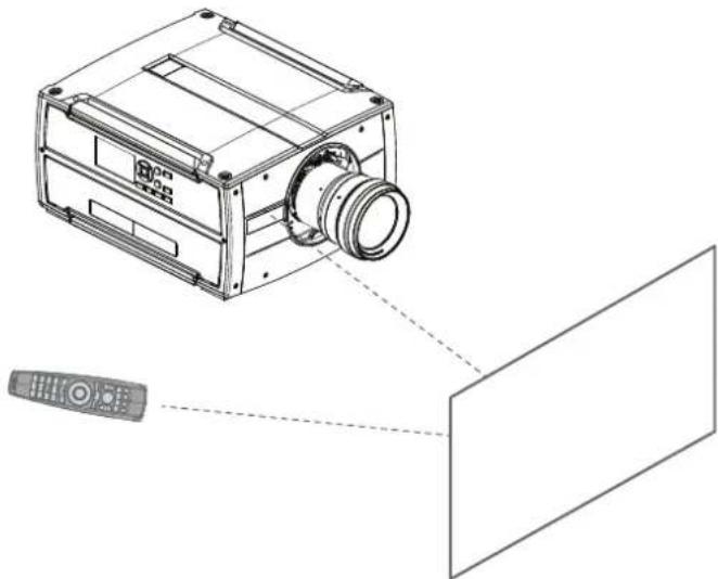
Switch on the RCU and point the front of the RCU to the reflective screen surface or point directly to projector IR sensors. Make sure you are within the effective operating distance (30 m, 100 ft in a str. The RCU will not function properly if strong light strikes the IR sensor window or if there are obstacles between the RCU and the IR receiver.
natural_image
Technical line drawing of a camera module with a remote control, showing no text or symbolsImage 7-1
The RCU can also hard-wired been used. See chapter "Using the mini-jack connector of the RCU", page 36.
7.2 Displaying and Programming addresses into the RCU

Projector address
Address installed in the projector to be individually controlled.

Broadcast address
Projector will always execute the command coming from a RCU programmed with that broadcast address.
Displaying the Projector Address on the Screen.
- If the projector is on, press the menu key and navigate to the Status page. The projector address and the broadcast address can be seen under the Communication heading.
The projector's address is displayed on the LCD status screen and / or the OSD.
How to Program an Address into the RCU?
- Press the Address button until the Button pressed indicator lights up continuously (proximately 5 seconds).
- Enter the address with the digit buttons within the time the indicator lights up (also proximately 5 seconds).

Note: That address can be any value between 0 and 31.

Tip: A few examples:
To enter address 3, press "3" digit button on the RCU to set the RCU's address to 3 and the button pressed indicator is out. Alternatively, you can also press "0" and "3". This way, the button pressed indicator goes out immediately.
To enter address 31, then press "3" and "1" on the digit button on the RCU and the button pressed indicator goes out immediately.

Placing new batteries in the remote control or plugging the remote to a projector via a cable automatically reset the address back to its default value '0'.
7.3 Setting the projector addresses

Projector address
Address installed in the projector to be individually controlled via the RCU or via the serial communication.

Broadcast address
Projector will always execute the command coming from a RCU programmed with that broadcast address.
About individual projector address
As more than one projector can be installed in a room, each projector should be separately addressab an RCU or with a computer using serial communication. Therefore each projector has its own address. factory default individual projector address is '0'.
When the address is set, the projector can be controlled with the RCU. Only addresses between 0 and supported for the RCU.
Next to an individual projector address, each projector has also a broadcast address for group control.
About broadcast address
Broadcast address is a common address that can be set on the projector. That can be "0" or "1". The broadcast address is '0'.
Any command coming from an RCU programmed with that common address will be executed.
How to set
- In the main menu, select System Settings > Communication > IR Control.
For detailed instructions see user guide of the projector.
7.4 Quick setup via Direct access
Quick source selection
- Press the Input button on the remote control or local keypad.
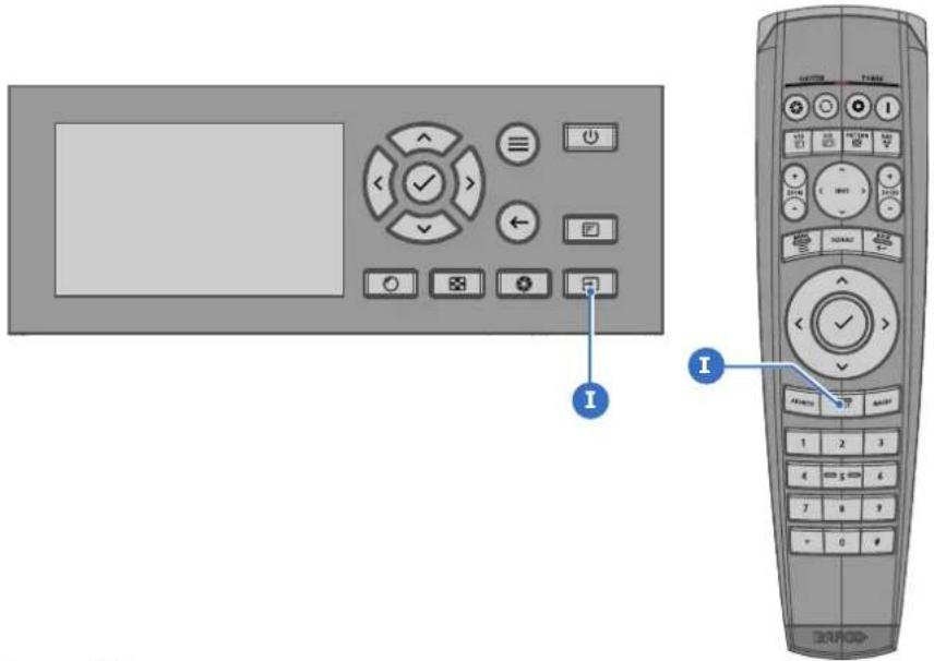
Image 7-2
The Source selection menu opens on the LCD display.
- Use the arrow keys to select the desired source.
Quick test pattern selection
- Press the Test pattern button on the remote control or local keypad.
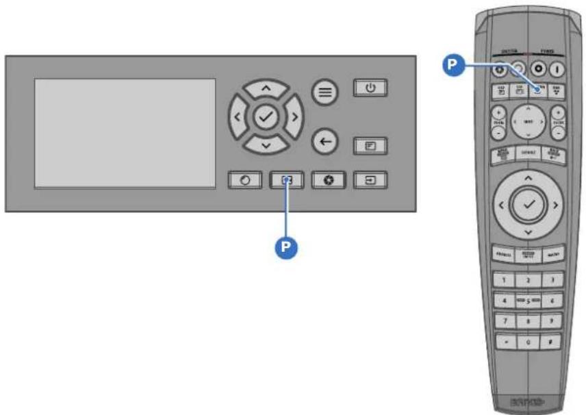
Image 7-3
The Test pattern menu opens on the LCD display.
- Use the arrow keys to select the desired test pattern.
7.5 Shortcut buttons
About the keypad shortcut buttons
On the keypad, there are three shortcut buttons; for lens function, test pattern selection, and input select. See "Local keypad", page 19 and "Pulse Remote Control Unit", page 27 for location and description. (The remote control has only the test pattern shortcut button).
When the test pattern or input shortcut button is pressed, a pop up menu will show up on the LCD Make a selection by the arrow keys, and confirm.
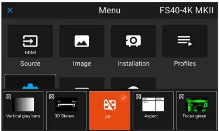
Image 7-4 Test pattern pop up menu
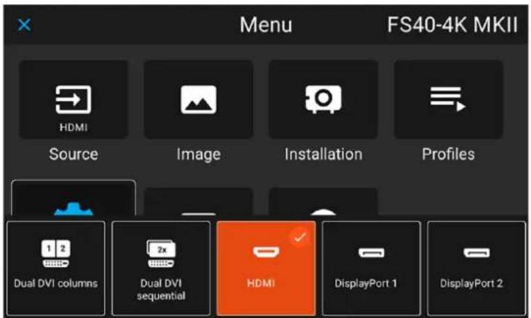
Image 7-5 Input source pop up menu
Input & Communication
8
8.1 Connector panel....54
8.2 Power on / Standby button backlight indications....55
8.3 Input source connections 56
8.4 Control Interfaces 57
8.1 Connector panel
General
The source input panel is located at the back of the projector. For source specifications, see table bel

Image 8-1
| Nr Name | Pcs | Description Purpose | ||
| 1 | RS-232 | 9-pin DB9 connector For projector control. Allows for wired remote control and monitoring of multiple projector functions used in installation environments | ||
| 2 | Sync 3 | BNC Sync Port IN/OUT; Bidirectional mini-DIN (1x 3D sync Out, and 2x Sync In/Out) | Used in multi-projector installations with requirement of synchronization between the syncits | |
| 3 | Trigger | 2 +12VDC - 0,5A (6W)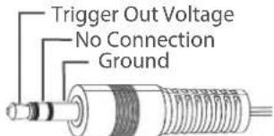 | For Controlling Peripherals (e.g. motorized screens, curtains etc.). Provides +12VDC output when activated. See Pulse API manual for more info.Note: Disconnect the projector power cable before connecting or removing the trigger cable | |
| 4 | RC | 1 MiniJack standard connector | Wired connection with Pulse RCU | |
| 5 | USB | 2 | USB 2.0, type A, 4 pin | Software upgrade and download projector log files |
| 6 | LAN | 1 RJ45 | standard connector Projector control | |
| 7 | DP | 2 DisplayPort 1.2 connector Source input | ||
| 8 | DL-DVI-D | 2 DVI-I | 1.0 connector with DVI_D functionality | Source input. Viable connectors for Stitched layouts.HDCP compliant for sources up 165 Mhz |
| 9 | HDMI | 1 HDMI | 2.0 connector Source input | |
| 10 | HDBaseT | 1 RJ45 | 8P8C Connector Source input and LAN over HDBaseT | |
8.2 Power on / Standby button backlight indications
Indicator
In addition to the LED indicator, the projector also displays status indications in the backlight of the P1 Standby button.
The table below shows the details regarding this indications.
| Operating Status | Indication Color / Behavior |
| On (active) Blue | |
| Wait on Blue flashing | |
| Standby (off) White | |
| Wait White short flashing | |
| Overheating Red flashing | |
| Configure/upgrade White fast flashing | |
| Standby ECO White heartbeat | |
| Software Lockup Red | |
| Severe errors Red Flashing |

When severe errors occur, the failure description will always be available in the notification page the status menu.
8.3 Input source connections

The source switching time is variable and could take few seconds..
Source signal connectivity
The connector panel at the back of the projector is used for all source connections.
Source signal connectivity on the projector is:
• 2x Dual Link DVI-I (DVI-D functionality)
- 2x DisplayPort 1.2
- 1x HDMI 2.0
- 1x HDBaseT
8.4 Control Interfaces

The HDBaseT input can also be used as a regular network port. See "Specifications" HDBaseT specification.
page 65
HDBaseT as network input
About
The following control interfaces are available on the projector:
• 1x RS-232 (for projector control)
• 1x LAN/Ethernet (for projector control
- 2x USB-A ports
8.4.1 RS-232
Specifications
| Parameter Value | |
| RS-232 connector 1 female DB9 connector (RS) | S232-in) for projector control and debug |
8.4.2 LAN/Ethernet
Specifications
| Parameter Value | |
| Ethernet connector 1 RJ45 Connector for projector control (not content) | |
| Protocols DHCP, TCP/IP, UDP/P | |
| Speed 10/100 Mbit/1000Mbit | |
8.4.3 USB-A port
Specifications
| Parameter Value | |
| USB connector | Type A |
| Function | Firmware update using a FAT-32 USB flash drive |
| Power | Power +5V, max 1.5 A (out) |
| Standard | USB 2.0 |
Maintenance
9
9.1 Software update....60
9.2 Projector lenses....62
9.3 Projector cabinet 63
9.4 Filters 64
9.1 Software update

CAUTION: Do not power off or unplug the projector while the software update is ongoing. Similarly, do not remove the USB flash drive while the software update is ongoing.
Prerequisites
First download the latest projector software package from the Barco's website.
Required tools
Projector Toolset
How to update the software using Projector Toolset
- Power on the projector. Wait until the Power on/off button is lit white or blue.
- Start Projector Toolset and make a connection with the projector. For more information, see the "Projector Toolset" user guide.
- Select tab Update settings.
- Fill out the path to the update file (1)

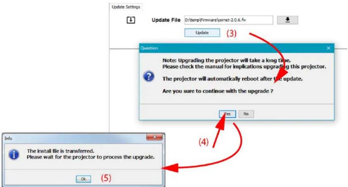
Image 9-1 Example of updating the software using Pulse Projector Toolset
or
click on the path selection icon (2) to open a browser window.
- Browse to the desired update package (format .fw) and click Select Update Package.
The path will be filled out in the input field next to Update File.
- Click Update (3).
The update starts. This action can take a long time. A dialog message will be prompted.
- Confirm with Yes to continue (4).
The update file will be transferred to the projector and will be installed.
A dialog message will be prompted once the update is completed. Click Ok to confirm.
How to update the software if the projector isn't connected to the network
-
Power on the projector. Wait until the Power on/off button is either lit white or blue.
-
Place the correct projector firmware file (format .fw) on a clean USB flash drive.

Note: Make sure the flash drive is FAT32 compatible & no other files are on the flash drive.
-
Place the projector in Ready mode.
-
Plug the flash drive in the USB port on the Communication Panel.
A software update dialog will be prompted on the LCD display, showing the version of the firmware Flash drive.
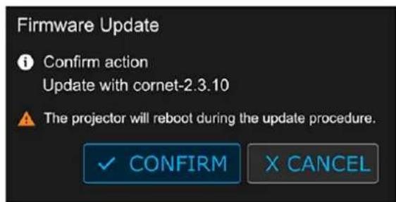
Image 9-2 Example of a Software update dialog prompt
- Select Confirm to start the software update process.

Note: Once initiated, the update procedure can take up to 20 minutes to complete. During this process the projector will reboot at least once.
The LCD display will show the current status of the update during the update process.
- Once the LCD display shows that the update process has been completed, it is safe to remove the USB flash drive.

CAUTION: While it is technically possible to "downgrade" the software to an older version using this method, it is NOT recommended and should be avoided as much as possible. Certain no longer be supported, projectors can display unwanted behavior during the downgrade some rare cases, this may even bring damage to the device. Always contact Barco if make sure a downgrade will not hurt your device.
features and in you war

For more info about the Projector Toolset see user guide of the Projector Toolset.
9.2 Projector lenses
General guidelines for cleaning projector lenses
Blow off dust with clean compressed air (or pressurized air cans).
Use lens cleaner and a clean lens cleaning cloth to remove the dust and contamination.
Wipe in broad strokes, in one direction only.
Warning: Do not wipe back and forwards across the lens surface as this tends to grind dirt into the
Use a dry clean lens cleaning cloth to remove left liquid or stripes. Polish with small circles.
If there are still fingerprints on the surface, repeat with lens cleaner and a clean lens cleaning cloth, again with a dry cloth.

If smears occur when cleaning lenses, replace the cloth. Smears are the first indication of a d cloth.
9.3 Projector cabinet

WARNING: Always disconnect the projector from the mains power net before attempting to clean the projector cabinet.
General guidelines for cleaning the projector cabinet (exterior only)
Clean the housing of the projector with a damp cloth. Stubborn stains may be removed with a cloth I dampened with a mild detergent solution.
9.4 Filters
General info regarding Air intake and filters.
The product is shipped default without any filters and by avoiding filters, the ventilation system operates longer periods between maintenance, since no clogging of filters means more air is allowed through the system, resulting in lower operating temperatures over time. The air intake are just protected by a mes mesh has to be vacuum cleaned occasionally when needed. No specific interval for this operation, but performed when needed.
For more demanding surrounds both smoke and dust filters can be applied externally to the system to internal fouling.
General guidelines for cleaning projector filters (external)
Remove the filter from the projector then use a vacuum to remove excess dust from the filter. Do no soak the filter.

Cleaning of the projector filter should be done in a separate room to avoid dust contamination.
Specifications
A
A.1 Specifications Bragi 66
A.2 Specifications Bragi CinemaScope 69
A.3 Specifications DVI-I inputs....72
A.4 Display Port 1.2....73
A.5 Specifications HDMI 2.0....74
A.6 Specifications HDBase T input....75
A.1 Specifications Bragi
| Projector type Single chip | DLP |
| Technology 0.9" DMDTM | |
| Resolution 3,840 x 2,160 (4K UHD) | |
| Aspect ratio 1.78:1 | |
| Light source Solid State RGB LED | |
| Light source lifetime Up to | 50,000 hours * Brightness mode dependent |
| Light output Up to 2,600 | ANSI Lumens |
| CLO (constant light output) | Yes |
| Contrast ratio 1,800:1 Sequential 450:1 ANSI | |
| Brightness uniformity >90% | |
| Lens range (R9802232) - EN68 (0.30:1) - Periscope Lens (requires vertical installation) (R9801832) - FLDX UST (0.41:1) - 90° Lens (R9802244) - EN67 (0.65:1) (R9802243) - EN66 (0.80 - 1.21:1) (R9802003) - EN76 (0.95 - 1.30:1) (R9802242) - EN63 (1.20 - 1.70:1) * (R9802241) - EN61 (1.70 - 2.50:1) * (R9801211) - EN44 (2.50 - 4.60:1) * Standard Lens Option(s) | |
| Optical lens shift | Up to 88% vertical lens shift & up to 38% horizontal lens shift (depending on lens selection) Visit the Barco Residential Lens Calculator for further information Download Lens & Airflow Data Here |
| Optical dowser | Yes |
| Color correction | P7 RealColorTM |
| Color gamut | REC.709 DCI (P3) via internal filter |
| Image processing | Embedded Warp & Blend Engine |
| WARP | 4-Corner Warp & Bow Correction via Warp Engine |
| Orientation | 360° Rotation |
| Network connection | 10/100 Ethernet via RJ45 connection |
| Integrated web server | Yes |
| Diagnostics | via Prospector web interface |
| HDR | HDR10 |
| 3D | Active Stereoscopic 3D Additional hardware required please contact an authorized Barco representative for details |
| Inputs 1 x HDMI 2.0 (HDCP 2.2)1 x HDBaseT (HDCP 1.4 - 9Gbps only)2 x Dual Link DVI-D2 x Display Port (1.2)12G-SDI1 x RJ45 Ethernet1 x RS2321 x Remote Control (RC)3 x USB (2 x Rear, 1 x Front)DMX (1 x Input, 1 x Output) | |
| Input resolutions From VGA up to 4K UHD (3,840 x 2,160) @ 60Hzor up to 2,560 x 1,600 @ 120Hz | |
| Latency TBD | |
| Control IR, RS232, IP, 12v | TriggerDriver modules available for: Crestron, Control4, RTI & SavantNOTE: 12v Trigger(s) do not follow standard functionality and req command to enable / disable them.Download our integration guide for more information. |
| Power requirements 100 - | 240V / 50 - 60Hz |
| Power consumption 570 W | - Max |
| BTU per hour 1,945 BTU/h | - Max |
| Noise level (typical at 25°C/77°F) | 30 - 33 dB(A) Max. |
| Operating temperature 10 to 45 °C at Sea LevelOptimal Set Point: 20 °C | |
| Operational humidity 20 to | 80% (relative humidity) |
| Airflow requirements Air Inlet (from Rear w/Feet Down): Right SideExhaust (from Rear w/Feet Down): RearClearance Requirements:Front: 1cmLeft: 1cmRight: 25cmRear: 25cmTop: 1cm | |
| Exhaust airflow | 58 ft3/min @ 22.9 °C99 m3/hour @ 22.9 °CDownload Lens & Airflow Data Here |
| Dimensions (WxLxH) Excluding lens | |
| Weight | Excluding lens21.5 kg / 47.4 lbs |
| Shipping Dimensions | Excluding lens464 x 679 x 773 mm18.27 x 26.7 x 30.4 in |
re an IP
| Shipping weight TBC | |
| Standard accessories Power | Cord, Remote Control |
| Certifications CE, FCC Class A and cCSAus | |
| Warranty Limited 3 years parts and labor Extendable up to 5 years | |
| 24/7 operation This projector is designed and warranted for heavy duty 24/7 operation. Specific measures and design considerations have been made in it to comply with stringent requirements in challenging applications | |
| * * Service required following 20,000 hours use Please contact an authorized Barco representative for details | |
A.2 Specifications Bragi CinemaScope
| Projector type Single chip | DLP |
| Technology 0.9" DMDTM | |
| Resolution 5,120 x 2,160 (5K UHD) | |
| Aspect ratio 2.37:1 (Cinema Scope) | |
| Light source Solid State RGB LED | |
| Light source lifetime Up to | 50,000 hours * Brightness mode dependent |
| Light output Up to 2,200 | ANSI Lumens |
| CLO (constant light output) | Yes |
| Contrast ratio 1,800:1 Sequential450:1 ANSI | |
| Brightness uniformity >90% | |
| Lens range (R9802232) - EN68 (0.30:1) - Periscope Lens (requires vertical installation)(R9801832) - FLDX UST (0.41:1) - 90° Lens(R9802244) - EN67 (0.65:1)(R9802243) - EN66 (0.80 - 1.21:1)(R9802003) - EN76 (0.95 - 1.30:1)(R9802242) - EN63 (1.20 - 1.70:1) *(R9802241) - EN61 (1.70 - 2.50:1) *(R9801211) - EN44 (2.50 - 4.60:1)* Standard Lens Option(s) | |
| Optical lens shift | Up to 122% vertical lens shift & up to 40% horizontal lens shift (depending on lens selection)Visit the Barco Residential Lens Calculator for further information Download Lens & Airflow Data Here |
| Optical dowser | Yes |
| Color correction | P7 RealColorTM |
| Color gamut | REC.709DCI (P3) via internal filter |
| Image processing | Embedded Warp & Blend Engine |
| WARP | 4-Corner Warp & Bow Correction via Warp Engine |
| Orientation | 360° Rotation |
| Network connection | 10/100 Ethernet via RJ45 connection |
| Integrated web server | Yes |
| Diagnostics | via Prospector web interface |
| HDR | HDR10 |
| 3D | Active Stereoscopic 3DAdditional hardware required please contact an authorized Barco representative for details |
| Inputs 1 x HDMI 2.0 (HDCP 2.2)1 x HDBaseT (HDCP 1.4 - 9Gbps only)2 x Dual Link DVI-D2 x Display Port (1.2)12G-SDI1 x RJ45 Ethernet1 x RS2321 x Remote Control (RC)3 x USB (2 x Rear, 1 x Front)DMX (1 x Input, 1 x Output) | |
| Input resolutions From VGA up to 4K UHD (3,840 x 2,160) @ 60Hzor up to 2,560 x 1,600 @ 120Hz | |
| Latency TBD | |
| Control IR, RS232, IP, 12v TriggerDriver modules available for: Crestron, Control4, RTI & SavantNOTE: 12v Trigger(s) do not follow standard functionality and req command to enable / disable them.Download our integration guide for more information. | |
| Power requirements 100 - | 240V / 50 - 60Hz |
| Power consumption 570 W | - Max |
| Noise level (typical at 25°C/77°F) | 30 - 33 dB(A) Max. |
| Operating temperature 10 to | 45 °C at Sea LevelOptimal Set Point: 20 °C |
| Operational humidity 20 to | 80% (relative humidity) |
| BTU per hour 1,945 BTU/h | - Max |
| Airflow requirements Air Inlet (from Rear w/Feet Down): Right SideExhaust (from Rear w/Feet Down): RearClearance Requirements:Front: 1cmLeft: 1cmRight: 25cmRear: 25cmTop: 1cm | |
| Exhaust airflow | 58 ft3/min @ 22.9 °C99 m3/hour @ 22.9 °CDownload Lens & Airflow Data Here |
| Dimensions (WxLxH) Excluding Lens | |
| Weight | Excluding Lens21.5 kg / 47.4 lbs |
| Shipping Dimensions | Excluding Lens464 x 679 x 773 mm18.27 x 26.7 x 30.4 in |
| Shipping weight TBC | |
| Standard accessories Power | Cord, Remote Control |
| Certifications CE, FCC Class A and cCSAus | |
| Warranty Limited 3 years parts and labor Extendable up to 5 years | |
| 24/7 operation This projector is designed and warranted for heavy duty 24/7 operation. Specific measures and design considerations have been made in it to comply with stringent requirements in challenging applications | |
| * * Service required following 20,000 hours use Please contact an authorized Barco representative for details | |
order for
A.3 Specifications DVI-I inputs
Specifications
| Parameter Value | |
| Connector DVI- I female digital RGB ( DVI-D | functionality) |
| Signal characteristics DVI 1.0, Digital, TMDS | |
| Max. cable length 25 m (24 AWG) | |
| Max. pixel rate 330 MHz (dual link), 165 MHz (single link) | |
| Scan format Progressive | |
| Max. input data resolution 1920x1200 60Hz (Single link)2560x1600 60Hz (Dual Link)1920x1200 @120 Hz (Dual link)1920x2400 @60Hz | |
| Bit depth 8 bit | |
| EDID Supported | |
| HDCP Supported |
A.4 Display Port 1.2
Specifications
| Parameter Value | |
| Connector Standard Display port | |
| Signal characteristics DP 1.2 | |
| Functionality Mandatory | |
| Max. cable length 2 m (24 AWG) - RBR; | 2 m (24 AWG) - HBR1, HBR2 |
| Supported Link Rate RBR, HBR1, HBR2 | |
| Scan format Progressive | |
| Max. input data resolution 2560x1600@120Hz | WQXGA / 3840x2400 @60Hz(4K ) Max |
| Bit depth 8, 10, 12 bit | |
| EDID Supported | |
| HDCP Supported |
A.5 Specifications HDMI 2.0
Specifications

Regarding HDMI 2.0: The decryption protocol HDCP 2.2 are enabled and valid in this unit.
| Parameter Value | |
| Connector Standard HDMI | |
| Signal characteristics Digital, TMDS | |
| Max. cable length 2 m (24 AWG) | |
| Max. pixel rate 594 MHz | |
| Max. input data resolution 3840x2160 @60Hz | |
| Bit depth 8, 10, 12 bits | |
| EDID Supported | |
| HDCP Supported | |
| Ethernet No | |
| Audio return No | |
| HDCP Supported |
A.6 Specifications HDBase T input

The HDBaseT standard allows the link to also be used as a regular network port. In addition carrying video data, it can also be connected to regular ethernet network without carry out any data.
Due to limitations in the projector and network standards, only the LAN and the HDBaseT should be used for network traffic, but not both simultaneously. If both are connected simultaneously it might lead to undefined behavior where traffic is not being sent on the link indicated by the IPaddress. This is only valid when the projector has a firmware version 2.1 or higher installed.
Specifications
| Parameter Value | |
| Reference specification HDBaseT 1.0 Specification, June 2010 | |
| Connector Standard RJ-45, 8P8C | |
| Signal characteristics HDBaseT | |
| Max. cable length (1080p/48b/60Hz) 100 m (Cat5e/6), Pixel Clock <=225HHz, Video Datarate <=5.3Gbps70 m (Cat5e/6), Pixel Clock >225HHz, Video Datarate >5.3Gbps100 m (Cat6a/7), Pixel Clock >225HHz, Video Datarate >5.3Gbps | |
| Max TMDS Clock Frequency 270 MHz | |
| Max video resolution supported 4096x2160 @30Hz | |
| HDCP Pass-Through Yes, from Source to Projector | |
| IR Extension Not Supported | |
| RS-232 Extension Not Supported | |
| 10/100Mbps Ethernet Pass-Through | Not Supported |
| Fallback to 100BaseTx, IEEE 802.3u | Not Supported |
| USB Over Centre Tap | Not Supported |
| Power Over Ethernet | Not Supported |
| Audio | Not Supported |
| LEDs - HD Base Status | Operation: Green, LeftLink/Mode: Yellow, Right |
Regulatory information
B
B.1 Contact information....78
B.2 Production address....79
B.3 Product compliance EU....80
B.4 Product compliance UK....81
B.5 Product compliance US....82
B.6 Product compliance Turkey 83
B.7 Product compliance EAC 84
B.8 Product compliance China....85
B.9 Product compliance Taiwan....87
B.10 Trademark notice....89
B.11 Product privacy statement....90
B.1 Contact information
Contact information
Barco NV
Beneluxpark 21, 8500 Kortrijk, Belgium
Barco Ltd., Taiwan
33F, No. 16, Xinzhan Rd., Banqiao Dist., New Taipei City 220, Taiwan
公司名稱:巴可股份有限公司
地址:新北市板橋區新站路16號33樓
Barco Fredrikstad AS
To find your local importer, contact Barco directly or one of Barco's regional offices via the contact inf given on Barco's web site, www.barco.com.
Registered offices
Registered office: Barco Fredrikstad AS
B.2 Production address
Made in information
The made in country is indicated on the product ID label on the product itself.
Production date
The month and year of production is indicated on the product ID label on the product itself.
Factory addresses
Factory: Barco NV
President Kennedypark 35, 8500 Kortrijk, Belgium
Factory: Barco (Wuxi) Technology Co., Ltd.
No. 38, Chunhui Middle Road, XiShan District, 214101 Wuxi CHINA
工厂:巴可(无锡)技有限公司
B.3 Product compliance EU
Disposal Information

Waste Electrical and Electronic Equipment (WEEE)
This symbol on the product indicates that, under the European Directive 2012/19/EU governing waste from electrical and electronic equipment, this product must not be disposed of with other municipal waste. Please dispose of your waste equipment by handing it over to a designated collection point for the recycling of waste electrical and electronic equipment. To prevent possibl harm to the environment or human health from uncontrolled waste disposal, please separate the items from other types of waste and recycle them responsibly to promote the sustainable reuse material resources.
For more information about recycling of this product, please contact your local city office or yc municipal waste disposal service. For details, please visit the Barco website at: https://www.barco.com/about/sustainability/waste-of-electronic-equipment-customers
Disposal of batteries in the product

This product contains batteries covered by the Directive 2006/66/EC which must be collected and disposed of separately from municipal waste.
If the battery contains more than the specified values of lead (Pb), mercury (Hg) or cadmium these chemical symbols will appear below the crossed-out wheeled bin symbol.
By participating in separate collection of batteries, you will help to ensure proper disposal and prevent potential negative effects on the environment and human health.
EMC notices Europe
EN55032/CISPR32 Class A MME (MultiMedia Equipment)
Warning : This equipment is compliant with Class A of CISPR 32. In a residential environment this equipment may cause radio interference.
B.4 Product compliance UK
UK Compliance

This product is fit for use in the UK.
Authorised Representative: Barco UK Ltd
Address: Building 329, Doncastle Road
Bracknell RG12 8PE, Berkshire, United Kingdom
B.5 Product compliance US
Federal Communications Commission (FCC Statement)
This equipment has been tested and found to comply with the limits for a class A digital device, purses Part 15 of the FCC rules. These limits are designed to provide reasonable protection against harmful interference when the equipment is operated in a commercial environment. This equipment generates, use and can radiate radio frequency energy and, if not installed and used in accordance with the instruction manual, may cause harmful interference to radio communications. Operation of this equipment in a residential area may cause harmful interference, in which case the user will be responsible for correcting any interest at his own expense
Changes or modifications not expressly approved by the party responsible for compliance could void the user's authority to operate the equipment
FCC responsible: Barco Inc.
3059 Premiere Parkway Suite 400
30097 Duluth GA, United States
Tel: +1 678 475 8000
B.6 Product compliance Turkey
Turkey RoHS compliance

B.7 Product compliance EAC
EurAsian Conformity (EAC)
EAC
This product complies with the Safety of Low-Voltage Equipment (LVE Technical Regulation 02011, CU TR 004/2011) and the Electromagnetic Compatibility of Technical Products (EMC Technical regulation, CU TR 020/2011) and Restriction of use of Hazardous Substances in ra and electronic devices (RoHS Technical regulation, CU TR 037/2016).
B.8 Product compliance China
EMC notices China
According to the “Management Methods for the Restriction of the Use of Hazardous Substances in Elec and Electronic Products” (Also called RoHS of Chinese Mainland), the table below lists the names and contents of toxic and/or hazardous substances that Barco’s product may contain.
| 零件项目(名称)Component name | 有毒有害物质或元素Hazardous substances and elements | |||||
| 铅(Pb) | 汞(Hg) | 镉(Cd) | 六价铬(Cr6+) | 多溴联苯(PBB) | 多溴二苯醚(PBDE) | |
| 印制电路配件Printed Circuit Assemblies | X | O | X | O O | O | |
| 外接电(线)缆External Cables | X O | O O O O | ||||
| 内部线路Internal wiring | X O | O O O O | ||||
| 镜头支架Lensholder | X O | O O O O | ||||
| 螺帽,螺钉(栓),螺旋(钉),垫圈,紧固件Nuts, bolts, screws, washers, Fasteners | X O | O O O O | ||||
| 电源供应器Power Supply Unit | X O | O O O O | ||||
| 风扇Fan | X O | O O O O | ||||
| 附電池遙控器Remote control | X O | O O O O | ||||
| 本表格依据SJ/T 11364的规定编制This table is prepared in accordance with the provisions of SJ/T 11364.O:表示该有毒有害物质在该部件所有均质材料中的含量均在 GB/T 26572 标准规定的限量要求以下.O: Indicates that this toxic or hazardous substance contained in all of the homogeneous ma part is below the limit requirement in GB/T 26572.X:表示该有毒有害物质至少在该部件的某一均质材料中的含量超出 GB/T 26572 标准规定的限量要求.X: Indicates that this toxic or hazardous substance contained in at least one of the homoge used for this part is above the limit requirement in GB/T 26572. | ||||||

All Electronic Information Products (EIP) that are sold within Chinese Mainland must comply with the “Marking for the restriction of the use of hazardous substances in electronic and electronic product” of Chinese Mainland, marked with the Environmental Friendly Use Period (EFUP) logo. The number inside the EFUP logo that Barco uses (please refer to photo) is based on the “General guidelines of environment-friendly use period of electronic information products” of Chinese Mainland.
B.9 Product compliance Taiwan
Product info

Image B-1
product name 產品名稱:
projector 投影機
model 型號: GP5
EMC notices Taiwan
BSMI Taiwan Class A statement
限用物質含有情況標示聲明書 (Declaration of the Presence Condition of the Restricted Substances Marking)
| 限用物質及其化學符號Restricted substances and its chemical symbols | ||||||
| 單元Unit | 鉛Lead(Pb) | 汞Mercury(Hg) | 鎘Cadmium(Cd) | 六價鉻Hexavalent chromium(Cr6+) | 多溴聯苯Polybrominated biphenyls(PBB) | 多溴二苯醚Polybrominated diphenyl ethers(PBDE) |
| 印製電路板配件Printed Circuit Assemblies | — | ○ — | ○ ○ | |||
| 外接電(線)纜External Cables | — | ○ ○ | ○ ○ | |||
| 內部線路Internal wiring | — | ○ ○ | ○ ○ | |||
| 鏡頭支架Lensholder | — | ○ ○ | ○ ○ | |||
| 螺絲組件Nuts, bolts, screws, washers, Fasteners | — | ○ ○ | ○ ○ | |||
| 電源供應器Power Supply Unit | — | ○○○ | ○○ | |||
| 風扇Fan | — | ○○○ | ○○ | |||
| 遙控器Remote control | — | ○○○ | ○○ | |||
| 備考1. “超出0.1 wt %”及“超出0.01 wt %”係指限用物質之百分比含量超出百分比含量基準值。Note 1: “Exceeding 0.1 wt %” and “exceeding 0.01 wt %” indicate that the percentage content of the restricted substance exceeds the reference percentage value of presence condition.備考2. “○”係指該項限用物質之百分比含量未超出百分比含量基準值。Note 2: “○” indicates that the percentage content of the restricted substance does not exceed the percentage of reference value of presence.備考3. “—”係指該項限用物質為排除項目。Note 3: The “—” indicates that the restricted substance corresponds to the exemption. | ||||||
備註:此RoHS表格適用於以下產品型號:GP5
Hint: This RoHS table is suitable for following models: GP5
B.10 Trademark notice
HDMI ^TM
The terms HDMI, HDMI High-Definition Multimedia Interface, HDMI trade dress and the HDMI Logos are trademarks or registered trademarks of HDMI Licensing Administrator, Inc.
DisplayPort™
DisplayPort™, the DisplayPort™ logo and DisplayPortHDR™ logo are trademarks owned by the Video Electronics Standards Association (VESA®) in the United States and other countries.
USB Type-C™
USB Type-C and USB-C are a registered trademarks of USB Implementers Forum
HDBaseT™
HDBaseT™ and the HDBaseT Alliance logo are trademarks of the HDBaseT Alliance.
PJLink™
The PJLink ^™ is a registered trademark of Japan Business Machine and Information System Industries Association.
DLP™
DLP® and the DLP logo are registered trademarks of Texas Instruments.

All other trademarks and registered trademarks are trademarks or registered trademarks of their respective holders. In this manual, ™ and ® marks are not specified.
B.11 Product privacy statement
About
Learn more about Barco's Product Privacy Statement: https://www.barco.com/en/about/trust-center/product-privacy-statement
Which data is captured and why
User names and IP addresses are captured for general secure operation of the product.
Data retention mechanism
An administrator should modify or delete a user (upon user request, or when the user doesn't work for company anymore), either via the Users feature, or via a factory reset executed as administrator.
Logs may contain user names and IP addresses and are subject to the retention policy, but can't be the user. The user can send a request to dataprotection@barco.com.
DMX chart
C
C.1 DMX chart, Basic....92
C.2 DMX chart, Extended....93
C.1 DMX chart, Basic
Overview
| Channel | Function Value | Default Action | |
| 1 | Shutter + Intensity | 0 - 7 255 Close shutter | |
| 8 - 255 Adjust | intensity | ||
| 2 | Function select 0 - | 7 0 No function | |
| 8 - 15 Activate | default macro (full screen) (If held for 1 second) | ||
| 16 - 23 Activate | macro 2 (If held for 1 second) | ||
| 24 - 31 Activate | macro 3 (If held for 1 second) | ||
| 32 - 39 Activate | macro 4 (If held for 1 second) | ||
| 40 - 47 Activate | macro 5 (If held for 1 second) | ||
| 48 - 55 Activate | macro 6 (If held for 1 second) | ||
| 56 - 63 Activate | macro 7 (If held for 1 second) | ||
| 64 - 71 Activate | macro 8 (If held for 1 second) | ||
| 72 - 79 Activate | macro 9 (If held for 1 second) | ||
| 80 - 87 Activate | macro 10 (If held for 1 second) | ||
| 88 - 95 Select | input 1: HDMI Input (If held for 1 second) | ||
| 96 - 103 Select | input 2: DisplayPort Input (If held for 1 second) | ||
| 104 - 111 Select | input 3: SDI Input A (If held for 1 second) | ||
| 112 - 119 Select | input 4: SDI Input B (If held for 1 second) | ||
| 120 - 127 Select | input 5: HDBaseT Input 1 (if held for 1 second) | ||
| 128 - 135 Select | input 6: Dual DisplayPort input (if held for 1 second) | ||
| 136 - 143 Select | input 7: DVI (if held for 1 second) | ||
| 144 - 151 Select | input 8: Dual DVI (if held for 1 second) | ||
| 152 - 159 Reserved | for future functionality | ||
| 160 - 167 Reserved | for future functionality | ||
| 168 - 175 Reserved | for future functionality | ||
| 176 - 183 Reserved | for future functionality | ||
| 184 - 207 Reserved | for future functionality | ||
| 208 - 115 | Power on / Light source on (If held for 5 seconds) | ||
| 216 - 223 Power down / Light source off (if held for 5 seconds) | |||
| 224 - 255 Reserved for future functionality | |||
C.2 DMX chart, Extended
Overview
| Channel | Function Value | Default Actions | |
| 1 | Shutter + Intensity | 0 - 7 2 | 55 Close shutter |
| 8 - 255 | Adjust intensity | ||
| 2 | Brightness 0 - 255 | 128 Adjusts the | brightness between 0 and 100% on input. |
| 3 | Contrast 0 - 255 | 128 Adjusts the | contrast between 0 and 100% on input |
| 4 | Input selection 0 - | 7 0 No | function |
| 8 - 15 | Activate default macro (full screen) (If held for 1 second) | ||
| 16 - 23 | macro 2 (If held for 1 second) | ||
| 24 - 31 | macro 3 (If held for 1 second) | ||
| 32 - 39 | macro 4 (If held for 1 second) | ||
| 40 - 47 | macro 5 (If held for 1 second) | ||
| 48 - 55 | macro 6 (If held for 1 second) | ||
| 56 - 63 | macro 7 (If held for 1 second) | ||
| 64 - 71 | macro 8 (If held for 1 second) | ||
| 72 - 79 | macro 9 (If held for 1 second) | ||
| 80 - 87 | macro 10 (If held for 1 second) | ||
| 88 - 95 | Select input 1: HDMI Input (If held for 1 second) | ||
| 96 - 103 | Select input 2: DisplayPort Input (If held for 1 second) | ||
| 104 - 1 | Select input 3: SDI Input A (If held for 1 second) | ||
| 112 - 1 | Select input 4: SDI Input B (If held for 1 second) | ||
| 120 - 127 | Select input 5: HDBaseT Input 1 (if held for 1 second) | ||
| 128 - 135 | Select input 6: Dual DisplayPort input (if held for 1 second) | ||
| 136 - 143 | Select input 7: DVI (if held for 1 second) | ||
| 144 - 151 | Select input 8: Dual DVI (if held for 1 second) | ||
| 152 - 159 | Reserved for future functionality | ||
| 160 - 167 | Reserved for future functionality | ||
| 168 - 175 | Reserved for future functionality | ||
| 176 - 183 | Reserved for future functionality | ||
| 184 - 255 | Reserved for future functionality | ||
| 5 | Focus (MSB) 0 - 2 | 55 128 | Set coarse lens focus adjustment ^2 |
| 6 | Focus (LSB) 0 | - 255 | 128 Set fine lens focus adjustment |
| 7 | Zoom (MSB) 0 | - 255 | 128 Set coarse lens zoom adjustment |
| 8 | Zoom (LSB) 0 | - 255 | 128 Set fine lens zoom adjustment |
| 9 | Lens shift vertical (MSB) | 0 - 255 | 128 Set coarse lens shift in vertical direction |
| 10 | Lens shift vertical (LSB) | 0 - 255 | 128 Set fine lens shift in vertical direction |
| 11 | Lens shift horizonta (MSB) | D - 255 | 128 Set coarse lens shift in horizontal direction |
| 12 | Lens shift horizonta (LSB) | D - 255 | 128 Set fine lens shift in horizontal direction |
| 13 | Light Source Power ^3 | 0 - 3 0 Set light Set light Set light | light source to 100% |
| 4 - 7 Set light | source to 95% | ||
| 8 - 11 Set light | light source to 90% | ||
| 12 - 15 Set light | light source to 85% | ||
| 16 - 20 Set light | light source to 80% | ||
| 21 - 23 Set light | light source to 75% | ||
| 24 - 27 Set light | light source to 70% | ||
| 28 - 31 Set light | light source to 65% | ||
| 32 - 35 Set light | light source to 60% | ||
| 36 - 39 Set light | light source to 55% | ||
| 40 - 43 Set light | light source to 50% | ||
| 44 - 47 Set light | light source to 45% | ||
| 48 - 51 Set light | light source to 40% | ||
| 52 - 55 Set light | light source to 35% | ||
| 56 - 59 Set light | light source to 30% | ||
| 60 - 63 Set light | light source to 25% | ||
| 64 - 67 Set light | light source to 20% | ||
| 68 - 71 Set light | light source to 15% | ||
| 72 - 75 Set light | light source to 10% | ||
| 76 - 79 Reserved for future functionality | |||
| 80 - 87 Power | on / Light source on (If held for 5 seconds) | ||
| 88- 95 Power down / Light source off (if held for 5 seconds) | |||
| 96 - 25 5 Reserved for future functionality | |||
| 14 | Various 0 | - 7 0 Reserved for future functionality | |
| 8 - 15 Calibrate lens zoom & focus (if held for 5 seconds) | |||
| 16 - 23 calibrate lens horizontal and vertical shift (if held for 5 seconds) | |||
| 24 - 31 Calibrate lens (zoom, focus and shift) | |||
| 32 - 25 5 Reserved for future functionality | |||
Glossary
Broadcast address
Projector will always execute the command coming from a RCU programmed with that broadcast address:
Projector address
Address installed in the projector to be individually controlled via the RCU or via the serial communicat
Projector address
Address installed in the projector to be individually controlled.
List of tools
Projector Toolset
Index
A
Address
Program
RCU 49
Adresses 78
B
Backlight 21
Basic RCU 23–24
Batteries 25
Battery
Disposal 4, 80
Specifications 66
C
Clean
lenses 62
Cleaning
cabinet 63
chassis 63
exterior 63
filters 64
lenses 59
projector 59
Communication 53
Compliance 14
China 85
EAC 84
EU 80
Taiwan 87
Turkey 83
UK 81
US 82
Components
Projector 17
Connections 56
Connector 73
Connector panel 54
Control 47
Control Interfaces 57
D
Disposal 3, 80
Battery 4, 80
DMX chart 91
Basic 92
Extended 93
DVI-I inputs
Specifications 72
E
ECO STANDBY 43
EurAsian Conformity (EAC) 84
F
Function
Button pressed indicator 32
G
General considerations 8
Getting started 15
H
Hazardous Chemicals 12
HDBaseT input
Specifications 75
HDMI 2.0 input
Specifications 74
Pulse RCU 48
|
Importer 78
Increasing the projector life time 45 Input 53
L
LAN/Ethernet 57
LCD 22
Link speed 40, 44
Local keypad 19, 21
Functions 20
M
mini-jack RCU 36
N
Notice on safety 8
0
ON 43
Operation in 24/7 Mode 46
Orientation Projector 16
OSD 22
P
Power
modes 40
Power off 42
Power on 41
Power On 43
Power on button 55
Power On/Off 39
Power up 41
Privacy 90
Production address 79
Projector
Address Setting 50
cleaning 59
Components 17
Orientation 16
Projector address 47
Pulse RCU 27 battery 29
Functionality overview 28
on/off button 31
Projector OSD on/off 34
protection sleeve 37
RGB button 33
RGB filter 33
Stealth Mode 34
Q
Quick setup 51
R
RCU
Address 49
mini-jack 36
XLR 35
RCU Basic 23
RCU batteries 25
RCU functions 24
RCU Pulse 27
READY 43
Regulatory information 77
Remote control 23, 27
RS-232 57
S
Safety 7
Battery explosion 11
Hazardous Chemicals 12
Safety Data Sheet (SDS) 12
Servicing 12
Safety Data Sheet (SDS) 12
Safety instructions 10
Safety labels 13
Shortcut buttons 52
Software update 60
Software upgrade 60
Specification 65
Specifications
Bragi CinemaScope 69
Bragi CS 69
DVI-I 72
HDBaseT 75
HDMI 74
Switching off 42
T
Touch panel 22
Trademarks 89
Turkey RoHS 3, 83
U
UK Compliance 14, 81
USB-A 57
User definition 8
W
Wake-On-LAN 40, 43–44
Wake-up on LAN 43
WEEE 3–4, 80, 83
WOL 40, 44
X
XLR
RCU 35
- Changes
- Federal Communications Commission (FCC Statement)
- Trademarks
- Turkey RoHS compliance
- Disposal Information
- Disposal of batteries in the product
- Guarantee and Compensation
- Copyright ©
- Software License Agreement
- Terms and Conditions:
- Disclaimer of Warranty:
- Table of contents
- Safety 7
- Getting started 15
- Local keypad 19
- Basic Remote Control Unit 23
- Pulse Remote Control Unit 27
- Powering On/Off 39
- Controlling the projector 47
- Input & Communication 53
- Maintenance....59
- A Specifications 65
- B Regulatory information....77
- C DMX chart....91
- Safety 1
- About this document
- Clarification of the term "Bragi" used in this document
- Model certification name
- General considerations
- General safety instructions
- Notice on safety
- Optical radiation safety precautions
- Users definition
- Important safety instructions
- To prevent the risk of electrical shock
- To prevent personal injury
- To prevent fire hazard
- To prevent battery explosion
- To prevent projector damage
- On servicing
- Malfunction unit
- Safety Data Sheets for Hazardous Chemicals
- Product safety labels
- Compliance
- Getting started 2
- Projector orientation
- Projector components
- Local keypad 3
- Local keypad functions
- Functionality
- Local keypad backlight
- Button backlight status
- LCD touch panel
- Navigation
- Basic Remote Control Unit
- 4
- About the basic remote
- Basic remote functions
- Basic remote batteries
- Battery placement & replacement
- Pulse Remote Control Unit
- 5
- Pulse RCU functions
- Pulse RCU battery installation
- About the batteries for the remote control
- How to install
- Pulse RCU on/off button
- Function of the remote control on/off button
- Pulse RCU "button pressed indicator"
- Functions button pressed indicator
- Pulse RCU "RGB filter" button
- Filtering the color of the projected image
- Pulse RCU "Projector OSD on/off" button
- Functions Projector on/off button
- Using the XLR connector of the RCU
- Revised RCU
- How to use the XLR connector
- Using the mini-jack connector of the RCU
- How to use the mini-jack connector
- Pulse RCU silicone protection sleeve (optional)
- Introduction
- Powering On/Off
- 6
- Power modes
- General
- Wake-On-LAN (WOL)
- Power up the projector
- Power up the projector using the keypad or remote
- Power Off the projector
- How to power off the projector
- How to unplug the projector
- Power mode transitions
- Transition diagram
- Increasing the projector lifetime
- Operation in 24/7 Mode
- Controlling the projector
- 7
- Using the RCU
- Pointing to the reflective screen or IR sensors
- Displaying and Programming addresses into the RCU
- Projector address
- Broadcast address
- Displaying the Projector Address on the Screen.
- How to Program an Address into the RCU?
- Setting the projector addresses
- About individual projector address
- About broadcast address
- How to set
- Quick setup via Direct access
- Quick source selection
- Quick test pattern selection
- Shortcut buttons
- About the keypad shortcut buttons
- Input & Communication
- 8
- Connector panel
- Power on / Standby button backlight indications
- Indicator
- Input source connections
- Source signal connectivity
- Control Interfaces
- HDBaseT as network input
- About
- RS-232
- LAN/Ethernet
- USB-A port
- Maintenance
- 9
- Software update
- Prerequisites
- Required tools
- How to update the software using Projector Toolset
- How to update the software if the projector isn't connected to the network
- Projector lenses
- General guidelines for cleaning projector lenses
- Projector cabinet
- General guidelines for cleaning the projector cabinet (exterior only)
- Filters
- General info regarding Air intake and filters.
- General guidelines for cleaning projector filters (external)
- Specifications
- A
- A.3 Specifications DVI-I inputs
- A.4 Display Port 1.2
- A.5 Specifications HDMI 2.0
- A.6 Specifications HDBase T input
- Regulatory information
- B
- B.1 Contact information
- Contact information
- Registered offices
- B.2 Production address
- Made in information
- Production date
- Factory addresses
- B.3 Product compliance EU
- EMC notices Europe
- B.4 Product compliance UK
- B.5 Product compliance US
- B.6 Product compliance Turkey
- B.7 Product compliance EAC
- B.8 Product compliance China
- B.9 Product compliance Taiwan
- EMC notices Taiwan
- B.10 Trademark notice
- HDMI TM
- DisplayPort™
- USB Type-C™
- HDBaseT™
- PJLink™
- DLP™
- B.11 Product privacy statement
- Which data is captured and why
- Data retention mechanism
- DMX chart
- C
- C.1 DMX chart, Basic
- C.2 DMX chart, Extended
- Glossary
- List of tools
- Index
- D
- E
- F
- G
- H
- |
- L
- M
- N
- 0
- P
- Q
- R
- S
- T
- U
- W
- X
Brand : Barco
Model : Bragi CinemaScope
Category : Projector