
S-patch Plus - Professional audio equipment SAMSON - Free user manual and instructions
Find the device manual for free S-patch Plus SAMSON in PDF.


| Product Type | 48-Channel Balanced Patchbay |
| Brand | Samson |
| Model | S-patch Plus |
| Number of Channels | 48 (24 pairs) |
| Connector Type | 1/4" TRS Balanced Phone Jacks (Front & Rear) |
| Operating Modes | Normalled, Half-Normalled, Thru (selectable per channel via mini-toggle switches) |
| Rack Size | 19 inches, 1U (1 space) rack-mountable |
| Front Panel | 48 jacks (top row and bottom row), 24 mini-toggle switches (one per pair) |
| Rear Panel | 48 jacks (top row and bottom row) |
| Power Requirement | Passive – no power required |
| Construction | Solid metal chassis, bead-blasted anodized aluminum front panel (blue) |
| Signal Path | Fully balanced, clean signal path |
| Warranty | 3-year extended warranty (requires registration) |
| Weight | Approximately 2.5 lbs (1.13 kg) |
| Dimensions (W x H x D) | 19 x 1.75 x 4.5 inches (483 x 44 x 114 mm) |
| Intended Use | Recording studios, live sound, home studios, patch bay for audio gear |
| Additional Features | Front panel mode switches for instant reconfiguration; eliminates need to reach behind rack |
| Compatibility | Works with mixers, multitrack recorders, outboard gear, MIDI instruments, etc. |
| Included Accessories | Warranty card, user manual (downloadable) |
| Country of Origin | Designed by Samson Technologies (USA) |
Frequently Asked Questions - S-patch Plus SAMSON
User questions about S-patch Plus SAMSON
0 question about this device. Answer the ones you know or ask your own.
Ask a new question about this device
Download the instructions for your Professional audio equipment in PDF format for free! Find your manual S-patch Plus - SAMSON and take your electronic device back in hand. On this page are published all the documents necessary for the use of your device. S-patch Plus by SAMSON.
USER MANUAL S-patch Plus SAMSON
Thank you for purchasing the S patch plus 48-channel, fully balanced patchbay by Samson Audio!
The S patch plus has been designed to provide a convenient, central point to make all your audio connections. Featuring solid construction with 48, 1/4 inch phone plugs on the front and 48, 1/4 inch phone plugs on the rear, the S patch plus will provide reliable operation while maintaining a clean signal path. In addition, the S patch plus features high quality, miniature toggle switches allowing each channel to be configured for either Normalled, Half-normalled or Thru operation. And since these mini-toggle switches are conveniently located on the front panel, you can instantly change any channels configuration without the need to remove the unit from the rack. Whether you're working in a personal studio or larger professional studio, using one or more S patch plus' will eliminate the need to make connections by reaching around the back of your mixer or equipment rack. S patch plus helps you work cleaner and faster, allowing you to focus on making a better production.
In these pages, you'll find a detailed description of the features of the S patch plus, as well as a description of its front and rear panels, step-by-step instructions for its setup and use and full specifications. You'll also find a warranty card enclosed—please don't forget to fill it out and mail it in so that you can receive online technical support and so we can send you updated information about these and other Samson products in the future.
We recommend you record your serial number in the space provided below for future reference.
Serial number:
Date of purchase:
Should your unit ever require servicing, a Return Authorization number (RA) must be obtained before shipping your unit to Samson. Without this number, the unit will not be accepted. Please call Samson at 1-800-3SAMSON (1-800-372-6766) for a Return Authorization number prior to shipping your unit. Please retain the original packing materials and if possible, return the unit in the original carton and packing materials.
S patch plus Features and Front Panel Layout
S patch Features

• 48 Channel, fully Balanced patchbay.
- Front panel, high quality, miniature toggle switches for selecting different configuration modes.
• Normal, Half-normal and Thru operation provides flexibility for wiring a variety of studio gear.
• 19-inch, 1u (1 space) rack-mountable unit.
• The sleek blue, bead blasted, anodized panel is as easy to read as it is to look at.
• Three year extended warranty.
Front Panel Layout

1 Top Jack - 1/4 Balanced phone jack.
2 Mode Switch - Miniature toggle switch selects between three operating modes, Normal, Half-normal and Thru.
3 Bottom Jack - 1/4 Balanced phone jack.
S patch plus Connections
A Little Background Before You Get Connected
A patchbay is one of the most useful additions to any recording studio, regardless of the size, as it provides a convenient way to make connections to various pieces of recording equipment such as multi-track recorders, computer hard-disk recorders, two-tracks and outboard signal processors. The S patch plus is constructed with 24 modules which have two, 1/4 inch phone jacks on the front and two, 1/4 inch phone plugs on the rear. These modules can be configured in various ways, but in many cases the S patch plus is set up as 24 channels of input and output pairs, or 48 channels of direct signals. It is also possible to configure the S patch plus with some channels configured in input and output pairs and others in direct signals. The S patch plus' modules can be configured in three different modes, Normalled, Half-normalled and Thru using the front panel mini-toggle switches. Before you decide on how to wire your new patchbay, you should understand the three operation modes. Follow the section below to configure the S patch plus channels.
Normalled Mode
The channel is set to Normalled mode when the mini-toggle switch is to the left position under the "N" legend. This configuration is commonly used to connect outputs from MIDI instruments or effects processors. In Normalled mode, the signal from the top rear jack is sent to the lower rear jack. When you insert a jack into the top front jack you "break the normal" and the signal is sent out of the top jack but is now disconnected from the bottom rear jack, with the bottom front jack providing the direct connection to the bottom rear jack.
The figure below shows the signal flow based on the connections of the front jacks.

flowchart
graph TD
    A["1: TOP FRONTREAR"] --> B["BOTTOM"]
    C["2: TOP FRONTREAR"] --> D["BOTTOM"]
    E["3: TOP FRONTREAR"] --> F["BOTTOM"]
    G["4: TOP FRONTREAR"] --> H["BOTTOM"]
S patch plus Connections
Half-normalled Mode
The channel is set to Half-normalled mode when the mini-toggle switch is to the right position under the "HN" legend. This configuration is commonly used for mixing console Insert Points. In Half-normalled mode, the signal from the top rear jack is sent to the lower rear jack. When you insert a jack into the top front jack you DO NOT "break the normal", so the signal is sent out of the top jack and is still connected to the bottom rear jack. This allows you to split the signal without interrupting the direct connection to the bottom rear jack.
The figure below shows the signal flow based on the connections of the front jacks.
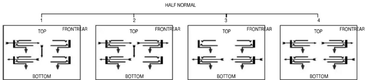
flowchart
graph TD
    A["1 HALF NORMAL"] --> B["2"]
    B --> C["3"]
    C --> D["4"]
    subgraph Top
        E["FRONTREAR"] --> F["TOP"]
        G["FRONTREAR"] --> H["TOP"]
        I["FRONTREAR"] --> J["TOP"]
        K["FRONTREAR"] --> L["TOP"]
    end
    subgraph Bottom
        M["BOTTOM"] --> N["FRONTREAR"]
        O["BOTTOM"] --> P["TOP"]
        Q["BOTTOM"] --> R["TOP"]
        S["BOTTOM"] --> T["TOP"]
    end
    subgraph Front
        U["FRONTREAR"] --> V["TOP"]
        W["FRONTREAR"] --> X["TOP"]
        Y["FRONTREAR"] --> Z["TOP"]
        AA["FRONTREAR"] --> AB["TOP"]
    end
Thru Mode
To set the S patch channel to operate in Thru mode, place the mini-toggle switch to the "T" position. When the channel is set to Thru the signal from the bottom rear jack is connected straight through to the bottom front jack, and the signal from the top rear jack is connected straight through to the top front jack. This configuration is used for connecting the outputs of MIDI sound modules or secondary 2-tracks like CD and cassette machines.
The figure below shows the signal flow based on the connections of the front jacks.

S patch plus Typical Set-Up




Above is an example of a typical patchbay set up for a project studio with an eight-track recorder, 16-input, eight-bus mixer, with four aux sends and inserts points on the buses and masters. This set-up also includes the facility to connect a 2-track, MIDI instruments and outboard effects like reverbs, delay lines, dynamics processors and equalizers. The patchbays are set up so most of the gear is already connected in a typical operating condition without the need to make connections with cables. The following is a description of each patchbay and its configuration.
On S patch plus number 1, the first eight channels are used to connect the mixer's bus outputs to the eight-track inputs. The mini-toggle switches are set to HN for Half-normal operation so that the buses are connected to the input of the eight-track without patching any cables. The next eight channels have the mini-toggle switches set to THRU since the top and bottom jacks of these channels will be used to connect the mixer's 16 direct outputs. Channels 17 and 18 are used to connect the mixers main stereo output to the input of the 2-track recorder (channels 41 & 42) and the output of the 2-track recorder (channels 19 & 20) is connected to the mixer's 2-track monitor input (channels 43 & 44). These channels are set to Half-normal mode. The last four channels are used to connect a cassette and a CD recorder, and since you don't want the recorders' inputs connected to the outputs, the channels are set to THRU mode.
S patch plus number 2 has the first eight channels configured in Half-normal mode with the eight-track outputs connected to the Line/Tape of the mixers input channel's 1-8. The next eight channels
S patch plus Typical Set-Up

flowchart
graph LR
    A["1 3 1 4"] --> B["3 7"]
    B --> C["3 8 3 9"]
    C --> D["1 5"]
    D --> E["1 6 1 7"]
    E --> F["4 0 4 1"]
    F --> G["MAIN OUT L & R"]
    G --> H["1 8 1 9"]
    H --> I["4 2"]
    I --> J["2 TRACK OUT L & R"]
    J --> K["4 3 4 4"]
    K --> L["2 MONITOR IN L & R"]
    L --> M["2 2 2 3 2 4"]
    M --> N["4 5"]
    N --> O["CASSETTE OUT L & R"]
    O --> P["4 6 4 7"]
    P --> Q["CD RECORDER OUT L & R"]
    Q --> R["4 8"]
    R --> S["SAMSON"]

flowchart
graph LR
    subgraph MIDI_INSTRUMENTS_5_8
        A1["1 3 1 4"] --> B1["T"]
        B1 --> C1["N RN"]
        C1 --> D1["3 7"]
        D1 --> E1["3 8 3 9"]
        E1 --> F1["1 5"]
        F1 --> G1["T"]
        G1 --> H1["N RN"]
        H1 --> I1["4 0 4 1"]
        I1 --> J1["1 6 1 7"]
        J1 --> K1["T"]
        K1 --> L1["N RN"]
        L1 --> M1["4 2"]
        M1 --> N1["1 8 1 9"]
        N1 --> O1["T"]
        O1 --> P1["R RN"]
        P1 --> Q1["4 3 4 4"]
        Q1 --> R1["2 0"]
        R1 --> S1["T"]
        S1 --> T1["R RN"]
        T1 --> U1["4 5"]
        U1 --> V1["2 1"]
        V1 --> W1["T"]
        W1 --> X1["2 2 2 3 2 4"]
        X1 --> Y1["4 6 4 7"]
        Y1 --> Z1["T"]
        Z1 --> AA["N RN"]
        AA --> AB["4 8"]
    end
    subgraph AUX_SEND_1_4
        AC["2 0"] --> AD["T"]
        AD --> AE["R RN"]
        AE --> AF["4 3 4 4"]
        AF --> AG["2 1"]
        AG --> AH["T"]
        AH --> AI["R RN"]
        AI --> AJ["4 5"]
        AJ --> AK["2 2 2 3 2 4"]
        AK --> AL["T"]
        AL --> AM["N RN"]
        AM --> AN["4 6 4 7"]
        AN --> AO["T"]
        AO --> AP["N RN"]
        AP --> AQ["4 8"]
    end
    subgraph EFFECTS_OUTPUT_1_4
        AR["2 0"] --> AS["T"]
        AS --> AT["R RN"]
        AT --> AU["4 5"]
        AU --> AV["2 1"]
        AV --> AW["T"]
        AW --> AX["R RN"]
        AX --> AY["4 6 4 7"]
        AY --> AZ["T"]
        AZ --> BA["N RN"]
        BA --> BB["4 8"]
    end
    subgraph SAISON
        BC["SAMSON"]


have the mini toggles set to N for Normal mode and eight outputs from a MIDI keyboard and drum machine are connected to line inputs 9 – 16. The next four channels are set to Half-normal and are used to connect the mixer's aux sends to the input of outboard signal processors. The last four channels are set to Half-normal mode and are used to connect the output of the effects processors to the mixers aux inputs.
S patch plus number 3 has the first 16 channels set up for the mixer's input channels insert points, followed by channels 17 – 20 for the bus inserts and 21 and 22 for the mixer's main left & right insert points. These channels have the mini-toggle switches set to HN for Half-normal mode. The last two channels are used to connect the mixer's control room output to the input of the studio monitor power amp.
S patch plus number 4 is used for Tie-lines to connect various outboard signal processors like compressors, noise gates, equalizers and delay lines. Additional MIDI instruments and other line level devices like CD, Mini-disk and DVD players or can be connected here as well. For these connections set the S patch plus's mini toggle to the T for THRU mode operation.
Note: It is not recommended to connect microphone outputs to any patchbay due to their low operation level.
Distributed Worldwide Exclusively by:
Samson Technologies Corp.
575 Underhill Blvd.
P.O. Box 9031
Syosset, NY 11791-9031
Phone: 1-800-3-SAMSON (1-800-372-6766)
Fax: 516-364-3888
www.samsontech.com
Brand : SAMSON
Model : S-patch Plus
Category : Professional audio equipment