
Alexa Mini LF - Camera ARRI - Free user manual and instructions
Find the device manual for free Alexa Mini LF ARRI in PDF.


| Product Type | Large Format Digital Cinema Camera |
| Brand | ARRI |
| Model | Alexa Mini LF |
| Sensor | Large Format ARRI ALEV III (A2X) CMOS with Bayer pattern color filter array |
| Sensor Size | 36.70 x 25.54 mm (diagonal 44.71 mm) |
| Pixel Pitch | 8.25 μm |
| Dynamic Range | 14+ stops (EI 160 to 3200) |
| Native Sensitivity | 800 ASA (base) |
| Shutter | Electronic shutter, 5.0° to 356° or 1 s to 1/8000 s |
| Recording Formats | MXF/ARRIRAW, MXF/Apple ProRes 4444 XQ, 4444, 422 HQ |
| Recording Media | Codex Compact Drive |
| Maximum Frame Rate | Up to 100 fps (depending on resolution and codec) |
| Lens Mount | ARRI LPL Mount (LBUS), interchangeable (PL, EF, M mount) |
| Viewfinder | Multi Viewfinder MVF-2 with 4" flip-out monitor, OLED 1920x1080 |
| ND Filters | Built-in motorized FSND filters 0.6, 1.2, 1.8 |
| White Balance | Manual and auto, 2000 K to 11000 K in 10 K steps |
| Audio | 4-channel 24-bit/48 kHz PCM, built-in microphones, line input, headphone out |
| Power Input | 11.0-34.0 V DC via 8-pin LEMO BAT connector |
| Power Consumption | 69-89 W (with MVF-2, depending on settings) |
| Weight | ~2.7 kg (camera body with LPL lens mount) |
| Dimensions (H x W x L) | 140 x 143 x 188 mm (5.5 x 5.6 x 7.4 in) |
| Operating Temperature | -20°C to +45°C (-4°F to +113°F) |
| Interfaces | 2x SDI (BNC), Ethernet, EXT, RS, 12V, AUDIO, TC, SYNC IN, LBUS, USB 2.0, WiFi, White Radio |
| Remote Control | MVF-2, Web Remote, CAP, WCU-4, OCU-1, Master Grip |
| Intended Use | Professional cinema production; for skilled personnel only |
Frequently Asked Questions - Alexa Mini LF ARRI
User questions about Alexa Mini LF ARRI
0 question about this device. Answer the ones you know or ask your own.
Ask a new question about this device
Download the instructions for your Camera in PDF format for free! Find your manual Alexa Mini LF - ARRI and take your electronic device back in hand. On this page are published all the documents necessary for the use of your device. Alexa Mini LF by ARRI.
USER MANUAL Alexa Mini LF ARRI
natural_image
Exterior view of a ARRI video camera with external control panel (no readable text or symbols beyond branding)Imprint
The system contains proprietary information of Arnold & Richter Cine Technik GmbH & Co. Betriebs KG; it is provided under a license agreement containing restrictions on use and disclosure and protected by copyright law. Reverse engineering of the software is prohibited.
No part of this publication may be reproduced, stored in a retrieval system, or transmitted in any form or by any means, electronic, mechanical, photocopying, recording or otherwise without the prior written permission of Arnold & Richter Cine Technik GmbH & Co. Betriebs KG.
Due to continued product development the information in this document may change without notice. The information and intellectual property contained herein is confidential between ARRI and the client and remains the exclusive property of ARRI. If you find any problems in the documentation, please report them to us in writing. ARRI does not warrant that this document is flawless.
ARRI, ALEXA Mini LF and ARRIRAW are trademarks or registered trademarks of Arnold & Richter Cine Technik GmbH & Co. Betriebs KG. All other brands or products mentioned are trademarks or registered trademarks of their respective holders and should be treated as such.

Apple ProRes 422 HQ, Apple ProRes 4444, Apple ProRes 4444 XQ, and the ProRes logo are trademarks or registered trademarks of Apple Computer, Inc., used under license therefrom.
Original version.
For Further Assistance
| Version | Release | Date |
| 6.0 | K10155 | July 15, 2019 |
| 6.0.15 | K10213 | September 10, 2019 |
| 6.0.22 | K10436 | September 17, 2020 |
| 7.0 | K10627 | April 20, 2021 |
| 7.1 | K10738 | August 4, 2021 |
| 7.2 | K11156 | February 15, 2023 |
1 Contents
1 Contents....3
2 Disclaimer....7
5 Audience and Intended Use.... 16
6 Scope of Delivery and Warranty.... 17
7 Introduction to the ALEXA Mini LF.... 18
8 Camera Layout....19
8.1 Camera Rear Connectors....21
8.2 Camera Left and Front Connectors.... 23
8.3 Media Bay....24
8.4 Product Identification....24
9 Camera Support....25
10 Power Supply....28
11 Lens Mounts and Lens Handling....30
11.1 ARRI LPL Mount (LBUS) and PL-to-LPL Adapter.... 30
11.2 ARRI EF Mount (LBUS)....31
11.3 Changing a Lens.... 32
11.4 Maximum Lens Mounting Depth....34
11.5 Changing the Lens Mount....34
11.6 Lens Data.... 36
12 MVF-2 Overview....38
12.1 Flip-out Monitor....40
12.2 MVF-2 Cables....41
13 Menu Operation....42
13.1 HOME Screen....43
13.2 Using the On-screen Keyboard....46
13.3 Working with Lists and Importing Files....47
13.4 Function Button FN....49
13.5 User Storage Handling....50
13.6 Info Screens....51
13.7 Alerts Screen....53
14 Main Parameters....54
14.1 Project Settings....54
14.2 Sensor Frame Rate....56
14.3 Shutter....56
14.4 Exposure Index....57
14.4.1 EF Lens Iris Adjustment....58
14.5 ND Filter....58
14.6 White Balance....58
14.7 Timecode....60
15 Look Settings....64
15.1 Processing and Color Spaces....66
16 Recording....68
16.1 Recording Medium....68
16.1.1 Erase of Recording Media....70
16.1.2 Remaining Recording Capacity and Media Information....70
16.2 Starting Recording via REC button....70
16.3 Recording Codec....71
16.4 Recording Resolution....73
16.5 Audio Recording....77
16.6 Rec Beeper and Tally Settings....79
16.7 File Naming Scheme....79
16.8 Data Handling....80
17 Playback....81
18 Monitoring....83
18.1 Status Information and Status Overlays....83
18.1.1 Flip-out Monitor Status Bar.... 86
18.1.2 Overlay Menu.... 86
18.2 Surround View....88
18.3 Magnification....90
18.4 Frame Lines....91
18.5 Anamorphic Desqueeze....93
18.6 Exposure Tools....94
18.6.1 False Color....94
18.6.2 Zebra....96
18.7 Focus Tools....97
18.7.1 Peaking....97
18.7.2 Zoom....97
18.8 SDI Outputs....99
18.8.1 Preventing Damage to SDI Outputs....101
18.9 EVF/Monitor Settings.... 102
18.10 Color Bars....103
19 Synchronization.... 104
19.1 EXT Sync....104
19.2 Genlock Synchronization.... 107
19.3 Timecode Synchronization....107
20 Sensor Settings....108
20.1 Noise Reduction.... 108
20.2 Mirroring the Sensor Image....108
20.3 User Pixel Masking....109
21 System Settings....111
21.1 Language Setting....111
21.2 System Time and Date....111
21.3 Button and Display Settings.... 111
21.4 Fan Settings....111
21.5 Battery Warning.... 111
21.6 Lens Mount Settings....111
21.7 Network and WiFi Settings....112
21.8 Reset of Electronic Horizon....115
21.9 Camera Update.... 115
21.9.1 Update of Camera Software....115
21.9.2 Update of Camera Components.... 115
21.9.3 Update of LBUS Devices.... 116
22 User Setups....117
22.1 User Setup Parameter Blocks....118
23 User Buttons....121
23.1 List of User Button Functions....122
24 Metadata....125
25 Electronic Control System (ECS)....127
25.1 White Radio Configuration....127
25.2 Lens Motors....128
25.3 Lens Data.... 129
25.3.1 Adding Lens Tables (LDA).... 130
26 Remote Control....131
26.1 Wireless Control Unit WCU-4....131
26.2 Web Remote....131
26.3 Camera Access Protocol (CAP).... 132
27 Transvideo Starlite HD5-ARRI Monitor....134
28 Appendix....136
28.1 Companion Tools....136
28.2 Connector Pin-Outs.... 138
28.3 Technical Data....140
28.4 Declarations of Conformity....143
28.5 ARRI Service Contacts....147
28.6 Dimensional Drawings....148
2 Disclaimer
Before using the products, be sure to read and understood all respective instructions.
The products are available for commercial customers only.
For product specification changes since this manual was published, refer to the latest publications of ARRI data sheets or data books, etc., for the most up-to-date specifications. Not all products and/or types are available in every country. Please check with an ARRI sales representative for availability and additional information.
ARRI assumes no responsibility for any errors that may appear in this document. The information is subject to change without notice.
While ARRI endeavors to enhance the quality, reliability and safety of their products, customers agree and acknowledge that the possibility of defects thereof cannot be eliminated entirely. To minimize risk of damage to property or injury (including death) to persons arising from defects in the products, customers must incorporate sufficient safety measures in their work with the system and have to heed the stated canonic use.
ARRI or its subsidiaries expressly exclude any liability, warranty, demand or other obligation for any claim, representation, or cause, or action, or whatsoever, express or implied, whether in contract or tort, including negligence, or incorporated in terms and conditions, whether by statute, law or otherwise. In no event shall ARRI or its subsidiaries be liable for or have a remedy for recovery of any special, direct, indirect, incidental, or consequential damages, including, but not limited to lost profits, lost savings, lost revenues or economic loss of any kind or for any claim by third party, downtime, good will, damage to or replacement of equipment or property, any cost or recovering of any material or goods associated with the assembly or use of our products, or any other damages or injury of the persons and so on or under any other legal theory.
Neither ARRI nor its subsidiaries assume any liability for infringement of patents, copyrights or other intellectual property rights of third parties by or arising from the use of ARRI products or any other liability arising from the use of such products. No license, express, implied or otherwise, is granted under any patents, copyrights or other intellectual property right of ARRI or others.
ARRI or its subsidiaries do not assume any responsibility for incurred losses due to improper handling or configuration of the camera or other system components, due to sensor contamination, occurrence of dead or defective pixels, defective signal connections or incompatibilities with third party recording devices.
In the case one or all of the foregoing clauses are not allowed by applicable law, the fullest extent permissible clauses by applicable law are validated.
▶ Always follow these guidelines to ensure against injury to yourself or others and damage to the system or other objects.
This safety information is in addition to the product specific operating instructions in general and must be strictly observed for safety reasons.
▶ Read and understand all safety and operating instructions before you operate or install the system.
▶ Retain all safety and operating instructions for future reference.
▶ Heed all warnings on the system and in the safety and operating instructions before you operate or install the system. Follow all installation and operating instructions.
▶ Assembly and operation should only be carried out by trained staff familiar with the system.
▶ Only use the tools, materials and procedures recommended in this document. For the correct use of other equipment, see the manufacturer's instructions.
▶ Do not subject the system to severe shocks.
▶ Do not point the camera sensor into direct sunlight, very bright light sources or high energy light sources (e.g. laser beams). This may cause permanent damage to the camera image sensor.
▶ Do not point the Viewfinder eyepiece into direct sunlight, very bright light sources or high energy light sources (e.g. laser beams). This may cause permanent damage to the viewfinder display and optical elements.
▶ When no lens is attached to the camera, immediately place the protective cap on the lens mount to avoid contamination of the sensor cover glass.
Safety warnings, safety alert symbols, and signal words in these instructions indicate different risk levels:
DANGER indicates an imminent hazardous situation which, if not avoided, will result in death or serious injury.
危险
WARNING indicates a potentially hazardous situation which, if not avoided, may result in death or serious injury.
警告
CAUTION indicates a potentially hazardous situation which, if not avoided, may result in minor or moderate injury.
小心
NOTICE explains practices not related to physical injury. No safety alert symbol appears with this signal word.
注意
Note: Provides additional information to clarify or simplify a procedure.
Risk of electric shock or fire!
Short-circuits may entail injury or equipment damage.
Usage of unsuitable accessories or non-approved parts of third party manufacturers may damage the system.
Do not repair any part of the system. Repairs must only be carried out by authorized ARRI service centres.
Do not remove or deactivate any safety measures from the system (incl. warning stickers or paint-marked screws).
Operate the system using only the type of power source indicated in the manual. Unplug the power cable by gripping the power plug, not the cable.
Unplug the system from the power outlet before opening any part of the system or before making any changes to the system, especially when changing lens mounts.
Do not operate the system in areas with humidity above operating levels or expose it to water or moisture.
Use only accessories recommended by ARRI. The use of accessories not recommended by ARRI is at your own risk. Please observe the relevant safety guidelines.
Risk of injury and damage!
Do not place the system on an unstable trolley or hand truck, stand, tripod, bracket, table or any other unstable support device. The system may fall, causing serious personal injury and damage to the system or other objects.
Assembly and operation should only be carried out by trained staff familiar with the system. Always place the camera on proper support devices. Safely attach it as described in the instructions. Always secure the system against tipping over / falling.
警告
触电或起火的风险!
短路可能导致人身伤害或设备损坏。
Condensation! Risk of electric shock and fire!
Condensation may form on the sensor and electrical connections when exposing the camera to sudden changes of temperature or humidity.
To avoid injury and damage, never operate the camera when condensation occurs.
Hot surfaces! Risk of injury and damage!
During extended operation, high data rates and/or operation at high ambient temperatures, the camera's surface, the area around the fan outlet and the recording media can get hot. Direct sunlight can result in camera housing temperatures above 60 °C (140 °F).
Never cover, obstruct or block the fan in- or outlets while the camera is powered. At ambient temperatures above 25 °C (77 °F), protect the camera from direct sunlight.
Be careful when removing the recording media. Wear protective gloves if necessary.
Crushing hazard!
Attachment of accessories like e.g. lenses, electronic and mechanical accessories poses a crushing hazard for fingers and/or hands.
When installing ARRI accessories or recommended third-party accessories (like e.g. lenses, mechanical accessories, electronic accessories) pay attention to the risk of crushing and always use the correct tools.
Risk of tripping over connected cables!
Always properly secure cables connected to the camera.
⚠ 小心
凝露有触电和起火的风险!
▶ Avoid touching optical surfaces.
▶ Avoid wiping optical surfaces without air blow dusting first. If particles or optical surfaces are electrostatically charged, it may improve dusting efficiency to use deionized air.
▶ Avoid compressed air from cans: the chances of liquid propellants within the can being expelled in liquid droplets against the glass, thereby leaving contaminants are quite great. If using compressed air, use it only in a clean environment to avoid aerosols being pulled into the air stream and propelled onto the surface. Always use oil-free compressed air with less than 2 ATM of pressure and equipped with particle filter.
▶ Use manual air blowers and clean antistatic brushes.
▶ Do not use any strong or aggressive cleaning detergents like Methanol, Acetone, Benzine or acids.
▶ When cleaning the system, do not moisten connectors.
▶ Clean optical lens surfaces only with a lens brush or a clean lens cloth. In cases of solid dirt or grease, moisten a lens cloth with pure alcohol. Discard contaminated lens cloth after use. Do not clean a lens brush with your fingers.
▶ If the sensor cover glass has been contaminated by solid dirt or grease, special optical cleaning kits should be used for dirt removal under very high care. If the contamination cannot be removed, the camera should be taken to an ARRI service center for cleaning.
避免接触光学表面。
▶ Always store and transport the camera in a suitable case.
▶ Do not store the camera in places where it may be subject to extreme temperatures, direct sunlight, high humidity, severe vibration, dust or strong magnetic fields.
▶ Do not subject the system to severe shocks.
When moving the camera from a cool to a warm location or when the camera is used in a damp environment, condensation may form inside the camera, on the sensor, and on internal or external electrical connections. Operating the camera while condensation is present may result in damage to the equipment. Condensation on the optical components may have a visible effect on the output images. To reduce the risk of condensation, find a warmer storage location. After moving the camera from cool to warm environment, wait for some time for the system to warm up to the ambient temperature to avoid condensation.
▶ Keep the protective cap on the lens mount when no lens is attached to the camera.
Single Frame Spots of Various Shape – also known as “Digital Dust” or “White Flecks”
Natural and/or artificial radiation may cause a “false exposure” on the image sensor. The shape of these spots may vary from dots to lines or other, sometimes irregular shapes. These spots occur in random locations of the image, last only for a single frame and are more visible in dark images. This is a principle issue of all image sensors and not a malfunction.
Some light sources (i.e. discharge tubes or LEDs) may cause an interference with sensor exposure. This may result in image flickering or "bands" of different brightness moving up or down the image. Please note that at higher frame rates (100 fps in 50Hz countries, 120 fps in 60Hz countries) even tungsten light may flicker. A short recording and playback will show this flicker.
For information on how to reduce flicker when filming a monitor please see "Shutter", page 56.
频闪
Due to the rolling shutter design principle of the sensor the following effects can be observed in certain situations:
- Skewed/slanted vertical lines: fast panning or fast-moving objects may result in vertical structures to appear "skewed/slanted". The intensity of the effect depends on the relative speed of panning/object.
- Partial exposure: very short light effects (i.e. a photographer's flash or strobe light) may result in the upper part of the image showing the light effect whereas the lower part does not or vice versa.
滚动快门
Very bright lights (i.e. the sun, or a photographer's flash) may result in a black/magenta spot. Note: pointing the camera directly into the sun may damage the sensor.
“黑太阳”
Stuck Pixels at Long Exposure Times
At longer exposure times (longer than the standard 1/50th of a second), stuck pixels may become visible in darker image areas. The longer the exposure time the more pixels will be affected. When using exposure times longer than 1/24th of a second, carefully check your image whether the quality meets your requirements.
长曝光时间的驻留像素
Stitching with ALEXA Mini LF
The ALEXA Mini LF sensor consists of a large sensor structure that is created by exposing two Super 35 sensor structures side by side onto a silicon wafer. This process is, somewhat misleadingly, called "stitching". As is common with stitched large format sensors in our industry, in rare situations it is possible to notice the boundary between the left and right image halves.
ALEXA Mini LF 的画面接合
5 Audience and Intended Use
The ALEXA Mini LF is a large format digital camera solely and exclusively for recording images at various resolutions suitable for a variety of distribution formats:
• Apple ProRes 422 HQ, Apple ProRes 4444, Apple ProRes 4444 XQ and ARRIRAW codec
• Rec 709 and Rec 2020 encoding (through use of look files), Log C or ARRIRAW encoding
• Codex Compact Drive recording
• Up to 100 fps with full image quality
• Large format CMOS sensor
• MVF-2 with OLED eyepiece and flip-out monitor for both live view and user interface access
• Small and lightweight built for high mobility and special applications
How To Use This Manual
All directions are given from a camera operator's point of view. For example, camera right side refers to the right side of the camera when standing behind the camera and operating it in a normal fashion.
Connectors are written in all capital letters, for example SDI 1.
Menu paths are written in italic typeface, with menu and home in capital letters, for example MENU > Recording or HOME > FPS.
Buttons are written in italic typeface capital letters, for example PLAY button.
The appendix at the back of the manual contains useful reference material including ALEXA Mini LF technical data, connector pin-out diagrams and dimensional drawings.
ADVICE
The product is solely and exclusively available for commercial costumers and shall be used by skilled personnel only. Every user should be trained according to ARRI guidelines.
Use the product only for the purpose described in this document. Always follow the valid instructions and system requirements for all equipment involved.
Additional Information
For useful information in addition to this user manual please have a look at the ARRI Learn & Help section on the ARRI website.
Strengthen Your Knowledge and Get Trained
The ARRI Academy courses provide unrivalled insights into the full possibilities of working with ARRI camera systems, lenses, lights and accessories.
To learn more, please visit http://arri.com/academy.
6 Scope of Delivery and Warranty
Delivery
On delivery, please check if package and content are intact. Never accept a damaged/incomplete delivery. A complete delivery includes:
• ALEXA Mini LF camera body
- Lens mount according to order
• USB memory stick incl. user manual
• Tool kit ALEXA Mini
• White Radio Antenna
- WiFi Antenna
• Original packaging incl. drying agent
ADVICE
Product and packaging contain recyclable materials. Always store, ship and dispose according to local regulations.
ARRI is not liable for consequences from inadequate storage, shipment or disposal.
ARRI offers an increasing variety of product bundles and additional accessories.
For details, please consult our website or your local ARRI Service Partner.
Warranty
For scope of warranty, please ask your local ARRI Service Partner. ARRI is not liable for consequences from inadequate shipment, improper use or third-party products.
7 Introduction to the ALEXA Mini LF
The ALEXA Mini LF (Large Format) camera is part of a complete large-format system that meets and exceeds modern production requirements. Based around a large-format 4.5K version of the ALEXA Mini sensor, the system comprises the ALEXA LF camera, ALEXA Mini LF camera, ARRI Signature Prime lenses, ARRI LPL Mount (LBUS) and ARRI PL-to-LPL Adapter. These system elements have been designed to take the fullest advantage of the enlarged sensor, while also offering maximum compatibility with existing lenses, accessories and workflows.
Featuring a sensor slightly larger than full frame, ALEXA Mini LF records native 4.5K with ARRI's best overall image quality. This allows filmmakers to explore an immersive large-format aesthetic while retaining the sensor's proven suitability for HDR and WCG workflows. Versatile recording formats, including efficient ProRes and uncompressed ARRIRAW up to 60 fps, as well as large format and Super 35 recording formats, provide unprecedented creative freedom.
ALEXA LF and ALEXA Mini LF have the biggest sensor area of any cinema camera on the market, second only to ARRI Rental's ALEXA 65. Maintaining the ALEXA family's optimal pixel size for highest overall image quality results in a 4448 x 3096 picture, which can be recorded in full using the LF Open Gate recording resolution. An LF 16:9 sensor mode maximizes lens options while meeting 4K deliverable standards, and an LF 2.39:1 recording resolution offers a cinematic widescreen image. All recording resolutions offer true 800 ASA sensitivity as well as reduced noise, providing the perfect canvas for modern, subtle lighting techniques.
A crucial element of the system is the LPL lens mount, with dimensions optimized for large format sensors. A wider diameter and shorter flange focal depth allow the ARRI Signature Primes and all future large format lenses to be small and lightweight with a fast T-stop and pleasing bokeh, a combination of features that would not be possible within the confines of the PL lens mount. The LPL mount is also available for other ARRI cameras such as the ALEXA Mini, ALEXA SXT or AMIRA so the ARRI Signature Primes can be used for large format and Super 35. In addition, the LPL mount is being licensed to other lens and camera manufacturers, creating a new universal standard.
Although camera, lens mount and lenses are new, compatibility with existing PL mount lenses and ALEXA Mini accessories is a cornerstone of the system's design. A PL-to-LPL adapter offers full backwards compatibility with all PL mount lenses, be they Super 35 or full frame. The PL-to-LPL adapter clips securely into the LPL lens mount without tools, so crews can rapidly switch between PL and LPL lenses on set, offering an unlimited lens choice to the cinematographer. Since the ALEXA Mini LF is based on the proven, robust ALEXA Mini camera design, most existing ALEXA Mini accessories will work right out of the box.
ALEXA Mini LF offers the same proven, versatile workflows as other ALEXA cameras. Recording at various resolutions is possible in uncompressed, unencrypted ARRIRAW up to 60 fps or in fast, efficient Apple ProRes up to 100 fps. Lens metadata can be recorded from LDS-1, LDS-2 or Cooke /i capable lenses. Existing ARRI Look Files (ALF-2) can be used with ALEXA Mini LF and the entire range of ARRI workflow software tools has been reworked to support ALEXA large-format images.
8 Camera Layout
Camera Right
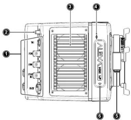
1 Rear Connectors
2 Radio Antenna Connector
3 Fan Intake
4 Sensor Plane Marking
5 LBUS Connector (on Lens Mount)
6 Integrated WiFi Antenna
Camera Left
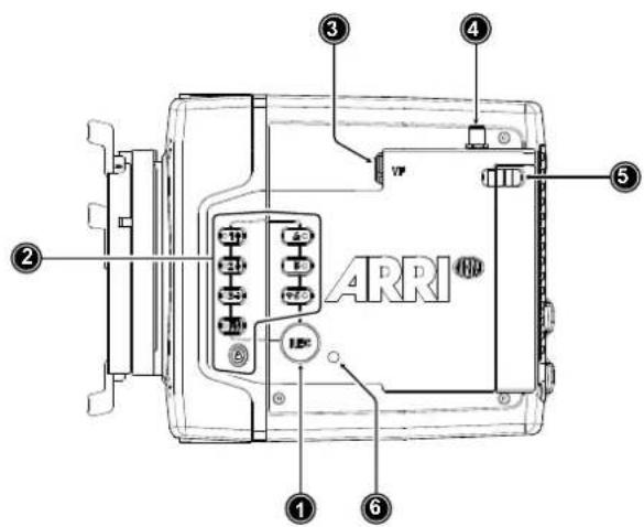
1 Record Button
2 Camera Buttons
3 VF Viewfinder Connector
4 WiFi Antenna Connector
5 Media Door Release
6 Camera Status LED
Camera Front
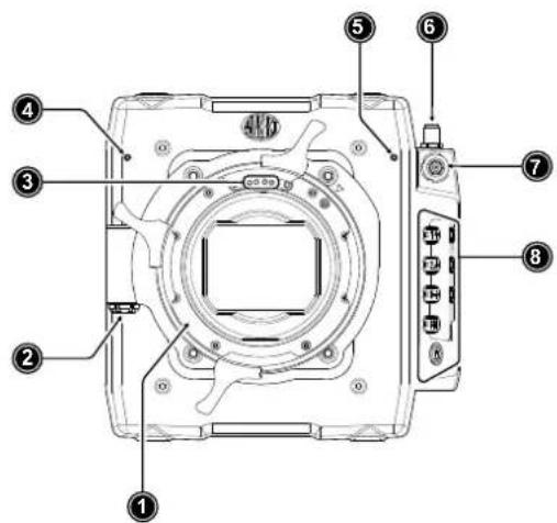
1 ARRI LPL Mount (LBUS)
2 LBUS Connector (on Lens Mount)
3 Lens Mount Contacts
4 Built-in Microphone (right)
5 Built-in Microphone (left)
6 WiFi Antenna Connector
7 VF Viewfinder Connector
8 Camera Buttons
Camera Rear
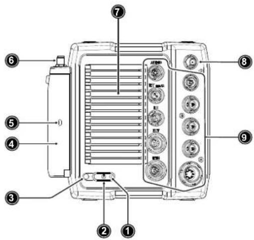
1 Boot Status LED
2 POWER Button
3 Camera Status LED
4 Media Door
5 Media Status LED Window
6 WiFi Antenna Connector
7 Fan Outlet
8 White Radio Antenna Connector
9 Rear Connectors
Camera Top
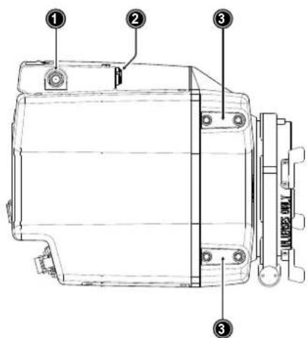
1 WiFi Antenna Connector
2 VF Viewfinder Connector
3 Attachment Points for Mechanical Accessories
Camera Bottom
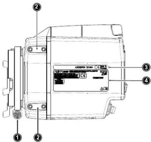
1 LBUS Connector (on Lens Mount)
2 Attachment Points for Mechanical Accessories
3 Camera ID Label
4 Certification Label
8.1 Camera Rear Connectors
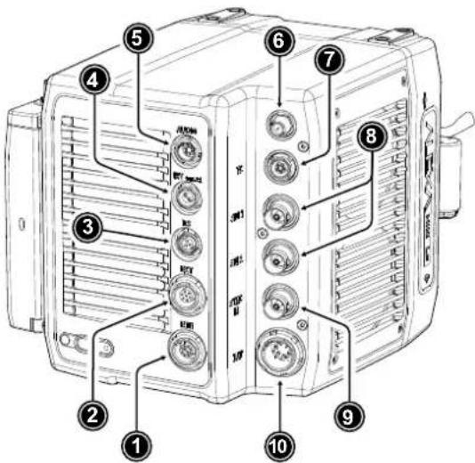
1 ETH Connector
2 EXT Connector
3 RS Connector
4 12V Connector
5 AUDIO Connector
6 White Radio Antenna Connector
7 TC Connector
8 SDI Outputs
9 SYNC IN Connector
10 BAT Connector
ETH (10-pin LEMO)
The Ethernet connector is used for camera remote control and service purposes. It supplies regulated 24 V with a current of 0.5 A. Use the ALEXA Ethernet Cable KC 153-S (K2.72021.0) to connect the camera to a standard RJ-45 Ethernet port.
Note: The ALEXA Remote Control Unit RCU-4 cannot be used with the Ethernet connector of the ALEXA Mini LF.
EXT (7-pin LEMO)
The EXT connector is a multi-pin accessory connector for camera synchronization and communication with various accessories, carrying two CAN buses and supplying regulated 24 V accessory power with a current of 1.0 A. With external adapter EXT-RS (K2.0006170), RS functionality (remote start/stop) is supported.
RS (3-pin Fischer)
The RS connector outputs regulated 24 V accessory power and can supply external devices with a load of up to 3.0 A. Besides powering accessories, the RS connector also carries a shutter pulse signal and can be used to send a remote start/stop signal to the camera.
12V (2-pin LEMO)
The 12 V output with a 2-pin LEMO connector supplies accessories with regulated 12 V with a current of 1.0 A.
AUDIO (6-pin LEMO)
The audio connector is a 2-channel +24 dBu line level audio input with an additional regulated 12 V power output with a current of 0.5 A. Use the ALEXA Mini LF Audio connector with cable (K2.0023988) to connect audio sources.
White Radio Antenna Connector (Female RP-SMA)
White radio allows for wireless lens control, lens data communication and remote control of basic camera functions using the wireless hand units of the ARRI Electronic Control System.
Note: Do not leave the antenna connector open during operation or transport. The radio module inside could be damaged by electrostatic discharge on the open connector. Use the originally supplied antenna only.
TC (5-pin LEMO)
The TC connector is a 5-pin LEMO socket. It accepts and distributes LTC (Longitudinal Timecode) signals. It can be used to
- jam-sync the camera timecode to a timecode generator or another camera
• transmit the camera timecode to a timecode generator or another camera
SDI 1 & SDI 2 (BNC)
Besides the viewfinder output, SDI 1&2 are the main monitoring outputs of the camera. The camera menu offers various settings to configure the outputs such as surround view, status information or frame lines. The SDI BNC connectors output SDI signals (legal range) in
• 1920 x 1080 (422 1.5G, 422 3G, 444 3G) (SDI 1 & SDI 2)
• 3840 x 2160 (422 6G) (SDI 2 only)
according to SMPTE standards 292M, ST 424:2012 and ST 2081.
SYNC IN (BNC)
A BNC socket for reference signal input, the SYNC IN connector accepts analog Black Burst signals and Tri-Level HD signals.
BAT (8-pin LEMO)
The BAT connector is the main power input of the ALEXA Mini LF and accepts an input voltage range from 11.0 to 34.0 V DC. You can use power cables KC50-S (K2.75007.0) or KC50-SP-S (K2.0001275) or one of the various on-board adapter plates for V-Mount and Gold Mount batteries to supply the camera with power.
ADVICE
Connecting or disconnecting devices or cables while recording can disturb the image/audio signal due to static electricity.
For information about connector pin outs please see "Connector Pin-Outs", page 138.
8.2 Camera Left and Front Connectors
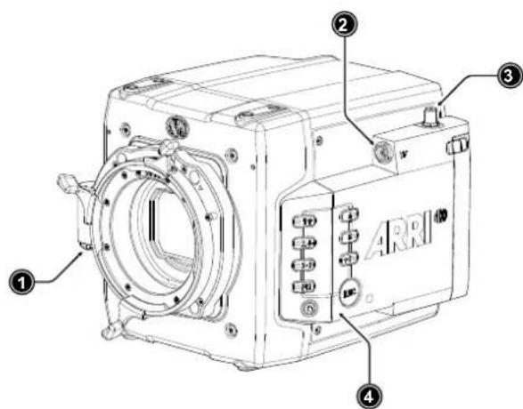
1 LBUS Connector (on Lens Mount)
2 VF Viewfinder Connector
3 WiFi Antenna Connector
4 Camera Buttons
LBUS Connector (4-pin LEMO, on LPL Lens Mount)
The LBUS connector is used to connect daisy-chainable LBUS devices of the ECS Electronic Control System (lens motors, ARRI Master Grips, ARRI OCU-1 and ARRI LCUBE CUB-1) to the camera and supplies regulated 24 V with a current of 2.0 A max.
VF Viewfinder Connector (CoaXPress)
The ALEXA Mini LF uses an industrial CoaXPress interface to connect the MVF-2 viewfinder with the camera. The interface transmits power, video and control data, supports hot plugging and supports cable lengths of up to 10 m (33 ft). The VF connector comes without a key, so the viewfinder cables plug in regardless of their orientation.
WiFi Antenna Connector (RP-SMA)
Besides the built-in WiFi antenna behind the camera label on the right side, the ALEXA MINI LF is equipped with a second WiFi antenna connector above the media bay on the camera left side. Both internal and external WiFi antenna work together, and if needed, the external antenna output can be disabled in the camera menu.
Note: Do not leave the antenna connector open during operation or transport. The radio module inside could be damaged by electrostatic discharge on the open connector. Use the originally supplied antenna only.
Camera Buttons
Besides the REC and LOCK button, the camera is equipped with six freely assignable user buttons plus a FN function button for quick access to frequently used functions. All buttons (except for the LOCK button) have an adjustable background illumination. For further information please see "User Buttons", page 121 and "Function Button FN", page 49.
8.3 Media Bay
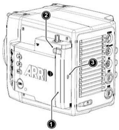
1 Media Bay Door
2 Media Bay Door Release
3 Recording Media LED Window
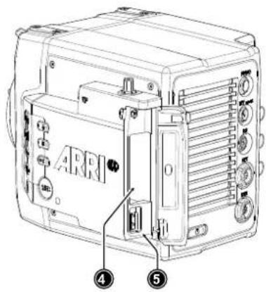
4 Recording Media Slot
5 USB Connector
Recording Media Slot
The ALEXA Mini LF records clips onto Codex Compact Drives, using the media bay on the camera left side. A small window (3) in the media bay door shows the LED of the Compact Drive. To access the media slot, slide the media bay door release (2) towards the camera back so that the spring-loaded door jumps open. For more information please see "Recording Media".
USB Connector
The camera saves data such as user setups, frame grabs and system logs to USB 2.0 memory sticks with FAT file system. Software updates, additional frame lines and ARRI look files are loaded onto the camera from the USB memory stick. The USB connector can also be used to charge USB devices and supplies 5.0 V with a maximum current of 0.5 A.
For more information please see "Working with Lists and Import of Files" and "User Storage Handling", page 50.
8.4 Product Identification
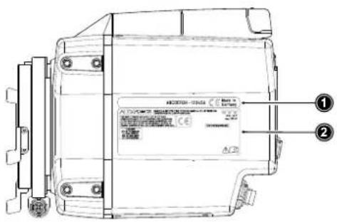
The camera serial number (1) and the FCC/CE conformity label (2) are located on the bottom of the camera. The serial number consists of the last 5 digits of the product number K1.0024074-XXXXX.
9 Camera Support
This chapter provides information on how to attach commonly used accessories to the camera.
ARRI offers a wide range of mechanical accessories, please see our Configuration Overviews for more information.
Mechanical accessories are attached to the M4 mounting points located on the front top and bottom of the camera. This chapter describes how to mount the most important mechanical accessories:
| Mini Adapter Plate MAP-2A(K2.0023839) | The MAP-2A is a base plate for 15 mm lightweight support and features an improved rod clamping mechanism as well as multiple 1/4-20 and 3/8-16 mounting points. It fits to the top and bottom of the ALEXA Mini / Mini LF. |
| Bridge Plate Adapter BPA-4(K2.0006352) | This spacer allows standard bridge plates to be mounted to the Mini Adapter Plate MAP-2 / MAP-2A. The BPA-4 also features centered 3/8 inch and 1/4 inch threads for standard tripod plates. Fits ALEXA Mini / Mini LF. |
| Bridge Plate BP-8(K2.0031436) | The BP-8 helps to optimize camera rig balance when combined with the range of ARRI bottom plates. It brings compatibility with studio 19 mm rod systems to an increasing number of ARRI and third party cameras. |
| Mini Side BracketsMSB-2 and MSB-3(K2.0014957, K2.0023546) | The Mini Side Bracket MSB-2 offers support for lens motor in configurations that require lightweight base plates with no rod support, such as lightweight stabilizer systems or drones. Suits ALEXA Mini, and also ALEXA Mini LF on camera right.The MSB-3 is a side bracket designed around the media bay of the ALEXA Mini LF and the new viewfinder connector on the camera left. |
| Center Camera Handle CCH-2(K2.73002.0) | The Center Camera Handle CCH-2 offers numerous mounting points in the industry standard 3/8-16 and 1/4-20 inch thread sizes. |
| Mini Viewfinder Bracket MVB-1(K2.0006140) | The MVB-1 allows the MVF-1 and MVF-2 viewfinders to attach to ALEXA Mini / Mini LF via 15 mm LWS rods and viewfinder mount. Requires the Mini Adapter Plate MAP-2A or other 15 mm rod support. |
Required Tools
• 3.0 mm Allen key
• 8-10 mm (5/16") flathead long shaft screwdriver
To avoid damage while assembling and retrofitting, always place the camera on a padded, firm, flat and level surface.
Mounting MAP-2A, BPA-4 and BP-8
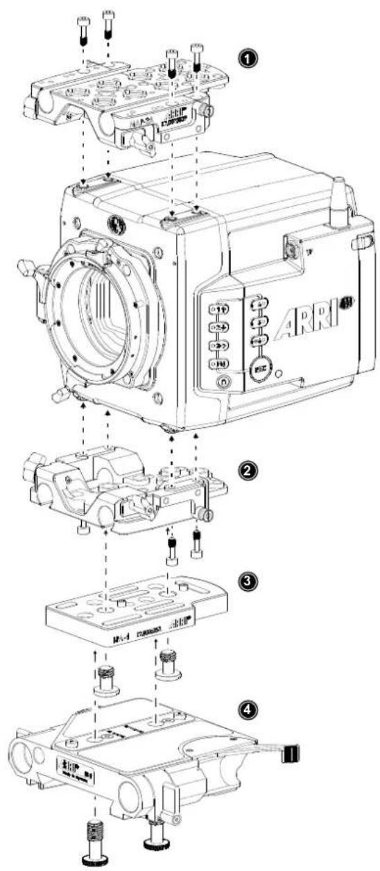
▶ Using a 3.0 mm Allen key, fasten the Mini Adapter Plate MAP-2 or MAP-2A (1) to the camera top attachment points with the four 3.0 mm hex screws. Tighten them cross-wise.
▶ Fasten another MAP-2 (2) to the bottom attachment points.
▶ Using a flathead screwdriver, fasten the Bridge Plate Adapter BPA-4 (3) to the bottom of MAP-2 (2) with two screws. Two register pins will assure a perfect fitting.
▶ Using a flathead screwdriver, fasten the Bridge Plate BP-8 (4) to the BPA-4 with two screws. Two register pins will assure a perfect fitting.
Mounting MSBs, CCH-2 and MVB-1
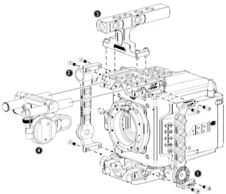
▶ Using a 3.0 mm Allen key, fasten the Mini Side Bracket MSB-3 (1) to the camera's left side. The MSB-3 is attached with two 3.0 mm hex screws each to the dedicated mounting points of the top and the bottom Mini Adapter Plates MAP-2A.
▶ Identical to the MSB-3 on the camera left side, fasten the MSB-2 (2) with four 3.0 mm hex screws to the camera's right side.
▶ Fasten the Center Camera Handle CCH-2 (3) to the top MAP-2A with four 3.0 mm hex screws.
▶ Open the clamps on the top MAP-2A and attach the MVB-1 (4) 15 mm LWS rods to the top MAP-2A.
CAUTION
When installing ARRI accessories or third-party accessories (like e.g. lenses, mechanical accessories, electronic accessories) pay attention to the risk of crushing and always use the correct tools.
10 Power Supply
BAT IN
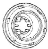
The ALEXA Mini LF accepts an input voltage range from 11.0 to 34.0 V DC. The camera can be solely powered through the 8-pin LEMO BAT connector located at the back of the camera. You can use the KC50-S (K2.75007.0) or KC50-SP-S (K2.0001275) power cable or one of the various on-board adapter plates for V-Mount and Gold Mount batteries to supply the camera with power.
ADVICE
Power solutions from ARRI (K2.0014530, K2.0014531, K2.0014532, K2.0014533) can be used safely up to a total current of 10 A (e.g. 144 W total at 14.4 V, including camera and powered accessories). For use cases demanding more than 10 A, alternative solutions such as block batteries or the B-Mount Power Splitting Box should be considered.
Accessory Power
24 V
The total available power on the 24V ACC converter is just below 100 W to be compliant with DIN EN 62368 PS2 (limited power source annex Q, table Q.1, single fault tolerant). The camera's 24V ACC converter power is shared by
- RS Connector
- EXT Connector
• LBUS Connector (on lens mount) - ETH Connector
Typically, the 24V ACC converter delivers a permanent current of 3.0 A at 14.0 V camera supply voltage and ambient temperatures of 25^ Celsius / 77^ Fahrenheit.
If the camera supply voltage is low, typically below 14.0 V (the camera is designed for Li-Ion based batteries that deliver about 14V until discharged to about 10-15%) the boost converter is current limited and the power on the 24V ACC converter is limited furthermore. Reason here is, that maximum current draw from the entire camera should not exceed 20A under all conditions since no on-board batteries can deliver higher currents.
12 V
The 12V ACC converter power is shared by
- 12V Connector
• AUDIO Connector
and outputs 12 V with a max. current of 2 A. If the camera supply voltage is below 13.5 V, the 12 V ACC converter power output is reduced by approx. 1,5 V.
Power Consumption
In order to process the increased pixel count while still maintaining ALEXA image quality, the ALEXA Mini LF draws between 69 W and 89 W while recording, with MVF-2 connected, but no further accessories attached. 69 W have been measured while recording MXF/ARRIRAW in recording resolution LF 16:9 UHD at 24 fps. 89 W have been measured while recording MXF/Apple ProRes in recording resolution LF 16:9 2K at 90 fps. Electronic accessories will increase power draw based on the accessories' draw.
ADVICE
- Always keep the BAT connector accessible so that the cable can be unplugged quickly in case of emergency. Do not use power cables longer than 4m.
- Operate the system using only the type of power source indicated in the manual. Unplug the power cable by gripping the power plug, not the cable.
- Do not supply power outside the specified voltage range.
Switching On and Off
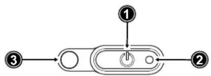
The POWER button is located at the lower left on the back of the camera. The power button's background light is illuminated when the power on the BAT connector is in the valid range.
flowchart
graph TD
    A["①"] --> B["②"]
    C["③"] --> D["②"]
    style A fill:#f9f,stroke:#333
    style B fill:#ccf,stroke:#333
    style C fill:#cfc,stroke:#333
    style D fill:#fcc,stroke:#333
1 POWER Button with background illumination
2 Boot Status LED
3 Camera Status LED
Switching On the Camera
The background illumination indicates if a supply with sufficient power is connected.
▶ Press the POWER button (1).
The camera starts booting. While the camera is booting up, the boot status LED (2) is flashing blue. As soon as the camera has finished the boot process, the boot status LED turns to solid blue. During the boot process, the ARRI logo is shown in the flip-out monitor of the MVF-2 (if connected).
Switching Off the Camera
▶ Press and hold the POWER button (1) until the camera has switched off and the boot status LED (2) turns off.
On the flip-out monitor of the MVF-2 as well as in the viewfinder and the SDI outputs, a countdown appears while you press and hold the power button. On reaching zero, the camera switches off.
Automatic Boot-up on Power
If the power supply is interrupted with the camera switched on, the camera will automatically repower and boot-up on reconnection.
11 Lens Mounts and Lens Handling
The ALEXA Mini LF is equipped with a universal lens mount base for interchangeable lens mounts allowing the use of various lenses.
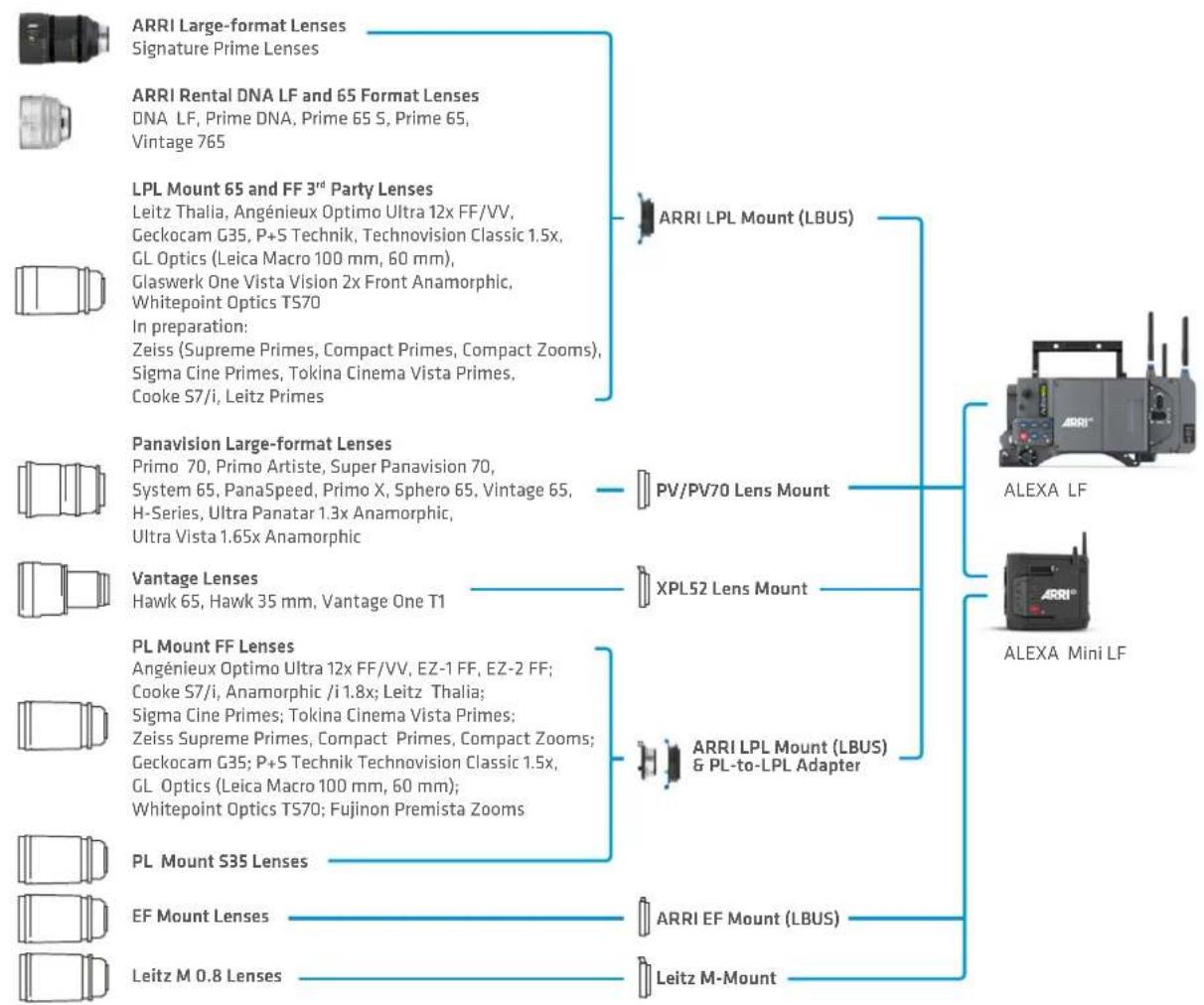
flowchart
graph TD
    A["ARRI Large-format Lenses<br>Signature Prime Lenses"] --> D["ARRI LPL Mount (LBUS)"]
    B["ARRI Rental DNA LF and 65 Format Lenses<br>DNA LF, Prime DNA, Prime 65 S, Prime 65,<br>Vintage 765"] --> D
    C["LPL Mount 65 and FF 3rd Party Lenses<br>Leitz Thalia, Angénieux Optimo Ultra 12x FF/VV,<br>Geckocam G35, P+S Technik, Technovision Classic 1.5x,<br>GL Optics (Leica Macro 100 mm, 60 mm),<br>Glaswerk One Vista Vision 2x Front Anamorphic,<br>Whitepoint Optics TS70<br>In preparation:<br>Zeiss (Supreme Primes, Compact Primes, Compact Zooms),<br>Sigma Cine Primes, Tokina Cinema Vista Primes,<br>Cooke S7/i, Leitz Primes"] --> D
    E["Panavision Large-format Lenses<br>Primo 70, Primo Artiste, Super Panavision 70,<br>System 65, PanaSpeed, Primo X, Sphero 65, Vintage 65,<br>H-Series, Ultra Panatar 1.3x Anamorphic,<br>Ultra Vista 1.65x Anamorphic"] --> F["PV/PV70 Lens Mount"]
    G["Vantage Lenses<br>Hawk 65, Hawk 35 mm, Vantage One T1"] --> H["XPL52 Lens Mount"]
    I["PL Mount FF Lenses<br>Angénieux Optimo Ultra 12x FF/VV, EZ-1 FF, EZ-2 FF;<br>Cooke S7/i, Anamorphic /i 1.8x; Leitz Thalia;<br>Sigma Cine Primes; Tokina Cinema Vista Primes;<br>Zeiss Supreme Primes, Compact Primes, Compact Zooms;<br>Geckocam G35; P+S Technik Technovision Classic 1.5x,<br>GL Optics (Leica Macro 100 mm, 60 mm);<br>Whitepoint Optics TS70; Fujinon Premista Zooms"] --> I
    J["PL Mount S35 Lenses"] --> K["ARRI LPL Mount (LBUS)<br>& PL-to-LPL Adapter"]
    L["EF Mount Lenses"] --> K
    M["Leitz M 0.8 Lenses"] --> K
    N["LEitz M-Mount"] --> K
    D --> O["ALEXA LF"]
    H --> P["ALEXA Mini LF"]
11.1 ARRI LPL Mount (LBUS) and PL-to-LPL Adapter
ARRI LPL Mount (LBUS)
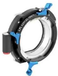
The ARRI LPL (Large Positive Lock) lens mount with LBUS connector fits ALEXA Mini LF, ALEXA Mini and AMIRA, it supports LDS-1, LDS-2 and Cooke/i and is compatible to the ARRI ECS LBUS devices such as the ARRI Master Grips, cforce lens motors and OCU-1 (Operator Control Unit). In comparison to the PL mount, the LPL mount has a wider diameter (62 mm vs. 54 mm) and a shorter flange focal distance (44 mm vs. 52 mm).
natural_image
Close-up of a mechanical clamp or bracket component with blue and black parts, no visible text or symbols.PL-to-LPL Adapter
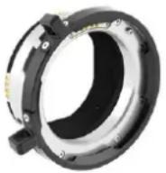
The PL-to-LPL adapter offers backwards compatibility with all PL mount lenses, be they Super 35 or full frame. The adapter attaches securely to the LPL lens mount without tools, allowing crews to rapidly switch between PL and LPL lenses on set. The PL-to-LPL Adapter can be mounted either so that the LDS contacts are in the 12:00 position for ARRI lenses, or so that the LDS contacts are in the 3:00 position for Cooke lenses. In both positions the adapter supports LDS-1 and Cooke /i.
The three most common uses of Super 35 PL lenses on the ALEXA Mini LF are:
1 Using an image expander.
2 Cropping the Super 35 area in post.
3 Using the large illumination circle of Ultra Primes, Master Primes or Ultra Wide Zoom (UWZ).
Some anamorphic lenses have their lens data connectors in the 3:00 position. In this case, use a 1.5 mm hex key to reposition the orientation pin of the PL to LPL adapter so that the lens can be mounted correctly.
ADVICE
The ALEXA Mini LF has the same interface between the camera and the lens mount as the ALEXA Mini and AMIRA. Therefore, physically, all lens mounts that fit on ALEXA Mini or AMIRA will also fit on ALEXA Mini LF. However, some of these lens mounts make little sense on the ALEXA Mini LF because they will show strong vignetting. The Titanium PL LDS mount with LBUS (K2.0003216) from the ALEXA Mini was designed for Super 35 only, we recommend against using this lens mount on the ALEXA Mini LF.
11.2 ARRI EF Mount (LBUS)
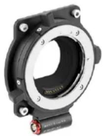
With the ARRI EF Mount (LBUS) (K2.0019965) the camera supports a wide range of EF lenses from Canon, Sigma, Zeiss and other manufacturers. The camera supports electronically controlling the iris and focus of these lenses through the camera user interface or accessories like the ARRI Master Grips. Furthermore, the EF lens mount powers the built-in image stabilizers of EF lenses.
natural_image
Close-up of a black mechanical component with a circular housing and mounting flanges (no visible text or symbols)EF Iris Control
The camera offers to control the iris via the auto iris feature or manually via user buttons, the camera menu or with the ARRI Master Grips.
For more information please see "EF Lens Iris Adjustment", page 58 and "List of User Button Functions", page 122.
ADVICE
The EF lens mount (K2.0001103) for AMIRA and ALEXA Mini is mechanically compatible with the ALEXA Mini LF, but vignetting may be visible on the ALEXA Mini LF when using large format EF mount lenses. Please note, that the amount of vignetting is based on the optical lens design, the focal length and the aperture, and therefore, we cannot provide information as to which lens will vignette how much. If you want to find out how much a given lens vignettes when using the EF lens mount for AMIRA and ALEXA Mini, we recommend shooting a test.
11.3 Changing a Lens
ARRI LPL Mount (LBUS), PL-to-LPL Adapter and PL Mount Lenses
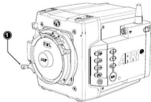
Lens change on the LPL mount, the PL mount as well as the PL-to-LPL Adapter works the same way. An LDS lens must be mounted with the LDS contacts in the 12:00 position to enable the LDS functions. Take care not to damage the LDS contacts on the lens and the camera when mounting or unmounting a lens or lens port cover. Any LDS-2 mount and any LDS-2 lens always have the contacts in the 12:00 position. The description below shows the ALEXA Mini LF with an LPL mount attached. When no lens is attached to the camera, use the lens port cap to prevent dust from entering the lens cavity.
Removing a Lens or the Lens Mount Cap
-
Turn the bayonet ring (1) anticlockwise until it stops. When removing a lens seure the lens with your hand when turning the bayonet ring.
-
Remove the lens port cap or lens.
Attaching a Lens
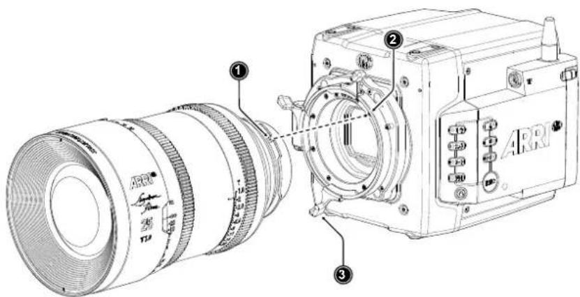
- Carefully insert the lens into the lens port. Align the notch in the lens flange (1) with the index pin on the lens mount (2), keeping the lens rotated into a position where the lens markings are visible from either side of the camera.
- Press the lens flange flat onto the lens mount.
- Turn the bayonet ring (3) clockwise until the lens is locked securely.
- Ensure that the lens is properly mounted.
ADVICE
Dust particles may settle on the sensor cover glass during a lens change!
Dust particles that have settled on the sensor cover glass during a lens change may become visible as dark spots in the output image, similar to lint leaving marks on exposed film. The degree of this effect depends on the aperture of the lens.
Changing lenses should be done in a dry and dust-free environment. If this is not possible, take extra care that no dust enters the camera while the lens is off.
After changing lenses, always perform a dust check to make sure no dust has settled on the sensor cover glass.
When no lens is attached to the camera, immediately place the protective cap on the lens mount to avoid contamination of the sensor cover glass.
Damage to Lens mount or camera!
Never exceed the maximum lens mount depth.
Do not short-circuit the LDS contacts.
Heavy lenses (above 3 kg / 6.6 lbs) require additional lens support. Using a lens support guarantees that the weight of the lens will not influence the flange focal depth and reduces stress on the lens mount.
CAUTION
When installing ARRI accessories or third-party accessories (like e.g. lenses, mechanical accessories, electronic accessories) pay attention to the risk of crushing and always use the correct tools.
Lens Support
To support a lens use 15 mm or 19 mm studio rods and an appropriate lens bridge. 15 mm rods require a bridge plate with 15 mm studio rod support, such as a BP-3 / BP-9 + MAP-2, while 19 mm studio rods require a bridge plate with 19 mm studio rod support, such as a BP-12 or BP-5 / BP-8 + BPA-4. Mount the Lens Support LS-10 for 15 mm rods by pushing it onto the rods from the front. Mount the Lens Support LS-9 for 19 mm studio rods by clipping it on the rods from the top. Slide the bridge into position on the rods directly under the lens support ring on the lens, and fix it in place by tightening the lever on its side. Align and tighten the center screw in the lens support ring, adjusting the height of the center screw with the lever on the back of the lens bridge.
11.4 Maximum Lens Mounting Depth
To avoid damage or injury when using LPL mount lenses or PL mount lenses (with PL adapter on LPL mount), use only lenses that do not exceed the following dimensions (left: LPL mount lenses, right: PL mount lenses):
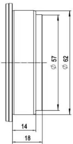
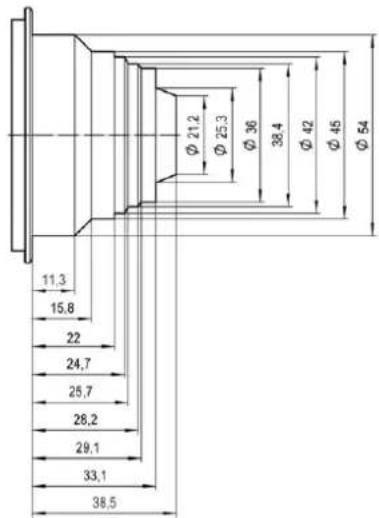
ADVICE
Risk of damage and injury from improper lenses!
To ensure maximum allowable lens mounting depth, and to avoid damage or injury, always have your camera shimmed correctly.
LPL mount lenses with more than 18.00 mm mounting depth and PL mount lenses with more than 38.50 mm mounting depth might damage internal filters and the camera. Shards from broken filter glass might cause injury. Always check the lens mounting depth before mounting or changing a lens.
11.5 Changing the Lens Mount
The ALEXA Mini LF is equipped with a universal lens mount base that uses the same camera to lens mount interface as used on the ALEXA Mini and AMIRA, so all lens mounts that fit on ALEXA Mini and AMIRA will physically also fit on the ALEXA Mini LF. However, since most of those lens mounts have been designed for a Super 35 sensor, they will show vignetting in larger format.
Required Tools and Precautions
• 3.0 mm Allen key
• Camera switched off and power source disconnected
- Lens removed and properly stored
• Make sure to protect all optical surfaces when changing a lens mount
Removing a Lens Mount (here: ARRI LPL Mount (LBUS))
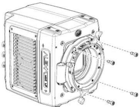
- Switch off the camera.
- Crosswise, loosen all four lens mount screws with a 3.0 mm Allen key.
- Carefully remove the lens mount.
- Store the lens mount in a case for dust protection and install a different lens mount.
Installing a Lens Mount (here: ARRI LPL Mount (LBUS))
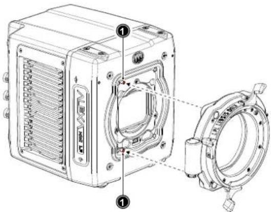
- Switch off the camera.
- Properly align the lens mount with the two guiding pins (1) on the camera's universal lens mount base.
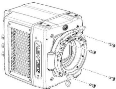
- Crosswise, hand-tighten all four lens mount screws with a 3.0 mm Allen key.
ADVICE
After each lens mount change, always check the flange focal depth of the camera.
Have the flange focal depth always corrected by properly skilled personnel.
Flange focal depth correction requires special tools and training that meet ARRI guidelines.
For all flange focal depth issues, contact a qualified ARRI Service Center.
When adjusting the flange focal depth on the LPL mount make sure to insert the shims in the correct orientation. Inserting the shims in the incorrect orientation (flipped) may result in a short circuit on the LDS print, compromising LDS functionality (lens detection and lens data).
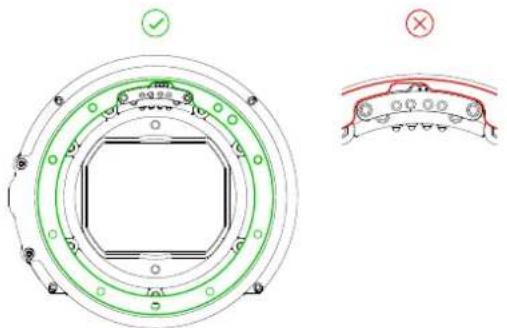
WARNING
High voltage! Risk of electric shock and fire!
Short circuits may entail lethal injury and damage!
Changing the lens mount while the camera is powered may permanently damage the camera and/or the lens mount.
Before each lens mount change, always switch off the camera and disconnect all power sources.
Protect sensor and electrical system: Always store the camera with a lens mount properly installed and capped. Immediately replace lens mount after removal. Change lens mounts in a dust-free environment only.
Condensation! Risk of electric shock and damage!
Humidity may ingress due to misinstalled lens mounts!
When installing a lens mount, always align and attach properly; never apply force. Hand-tighten all screws crosswise before final tightening. Always tighten crosswise with the recommended tool.
11.6 Lens Data
ARRI Lens Data System (LDS)
ARRI's Lens Data System (LDS) comprises a range of products generating highly accurate lens metadata for use on set and in post. LDS describes digital lens settings. Lenses with LDS functionality deliver information about its current settings (focus distance, iris, focal length) to the camera; the camera interprets these values and transmits the information to its recording module and optionally to any further accessories connected to the camera such as a Wireless Compact Unit WCU-4 or ARRI Master Grips. Lens data is displayed in the viewfinder and as overlays on the SDI outputs, and all lens data will be embedded in the recorded files as well as the SDI stream.
LDS-2 is the next evolution of ARRI's Lens Data System for ARRI's Electronic Control System and a new generation of lenses. LDS-2 delivers more accurate and faster lens data. Compared to LDS-1 it eliminates the need for initial calibration through absolute encoders which cuts time on set when changing lenses. The new system uses a 8.7x faster interface that enables lens manufacturers to send more data to the camera than before. LDS-2 extends the possibilities of lens data and is being licensed to other lens and camera manufacturers.
For more information about the Lens Data System, please visit our Lens Data System FAQs web page.
ARRI Lens Data Archive (LDA)
Lenses without LDS can be integrated into the system via the Lens Data Archive (LDA). By mapping a lens, all information about the lens, its scales, name, and serial number can be transferred into a lens archive. When using the lens the next time all that has to be done is to load the lens file for that lens from the Lens Data Archive and calibrate the motors. It takes about 5 minutes to map a lens: after attaching the lens and connecting and calibrating motors (or Lens Data Encoders) on each axis of the lens, the mapping can be done with the Wireless Compact Unit (WCU-4). These lens files can be loaded to the camera.
Cooke /i
The LPL mount also offers basic Cooke /i support for direct lens metadata capture through the LDS contacts. The cameras can store a subset of /i lens data (focus distance and iris settings) as dynamic camera metadata. The basic /i compatibility has been tested and approved by Cooke Optics Limited. For support and questions about /i Technology, please contact Cooke Optics directly.
The camera supports the Cooke /i protocol for lenses running firmware versions according to the following table.
| Lens type FW version | |
| S4 /i Prime lens (10-bit) 0.29 or higher | |
| S4 /i Prime lens (12 bit) 0.39 or higher | |
| S4 /i Zoom lens (10 bit) 1.29 or higher | |
| S4 /i Zoom lens (12 bit) 1.39 or higher |
The firmware version can be retrieved from the lens with the Cooke Viewer Lens Display program. For detailed information, please contact Cooke Optics directly.
Lens Data Display in Camera
Lens data can be displayed as camera status overlays in the viewfinder and the SDI outputs. Single overlays for focus distance, iris and focal length are displayed. The camera can be set to display either metric or imperial readings for the focus distance overlay. For further information please see page 85.
Lens Data in Metadata
Lens data is dynamically written to the metadata of MXF/Apple ProRes and MXF/ARRIRAW files and is output in the SDI stream.
Metadata values include
- Lens Model
- Lens Serial Number
- Lens Distance Unit
- Lens Focus Distance
- Lens Focal Length
- Lens Iris
12 MVF-2 Overview
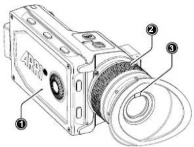
1 Flip-out Monitor
2 Diopter Adjustment
3 Proximity Sensor
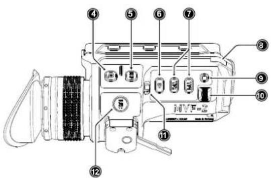
4 ZOOM Button
5 EXP Button
6 PLAY Button
7 VF 1&2 User Buttons
8 Top Tally Light
9 SET Button
10 User Wheel
11 LOCK Switch
12 REC Button
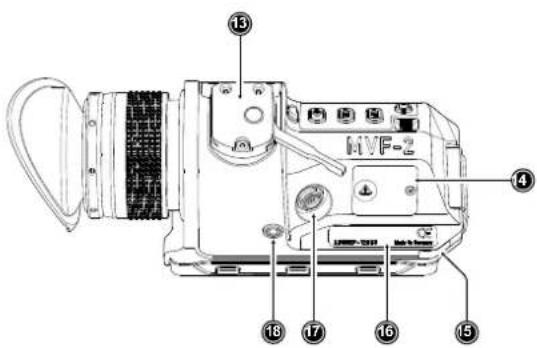
13 Dove Tail
14 Service Cover
15 Bottom Tally Light
16 Product Label
17 Viewfinder Connector
18 Headphones Out
OLED Display
The MVF-2 is equipped with a high contrast, temperature controlled 1920 x 1080 OLED display.
Flip-out Monitor
The 4" flip-out monitor (1) with up-and-down tilt function can display the camera live image or the main user interface, providing full access to camera functions and menus. See the next chapter for more information.
Diopter Adjustment
With the camera switched on and looking into the viewfinder, twist the ring (2) left or right to adapt the viewfinder image to your visual acuity. With the help of the scale labelled from 1 to 9 you can easily remember your adjustment when different people are using the viewfinder. The diopter adjustment can compensate from -5 to +5 diopters.
Proximity Sensor
This infrared sensor (3) automatically deactivates the MVF-2's internal OLED panel when you withdraw your eye to prevent burn-ins on the panel and activates it again as soon as you approach the eyepiece. Do not permanently cover the sensor as this might cause irreversible burn-in on the OLED panel.
Built-in Eyepiece Heater
The MVF-2 is equipped with a built-in eyepiece heater to prevent fogging of the eyepiece when shooting in cold environments. The eyepiece heater can be activated in the camera menu and only becomes active when the eyepiece has a temperature of 15 ^ ( 59 ^ ) or below. In extremely cold environments please use the Heated Eyecup HE-7.
EXP (Exposure Tool Button)
The EXP button (4) activates and deactivates the exposure tool (either false color or zebra) for the viewfinder and the flip-out monitor.
ZOOM Button
Pressing the ZOOM button (5) activates the viewfinder zoom feature for a temporary zoom-in to quickly check focus. The magnification ratio is 1:1, or one sensor pixel to one viewfinder display pixel.
PLAY Button
Press and hold the PLAY button (6) for two seconds to start in-camera playback from the recording media.
VF1 and VF2 User Buttons
The MVF-2 has two user buttons, VF1 and VF2 (7). You can assign a frequently used function to each button.
User Wheel and SET Button
The user wheel and the SET button (9, 10) provide the same functionality as the JOGWHEEL on the flip-out monitor (see next chapter) and can be used for menu navigation and adjustment when the flip-out monitor is used with the display visible in the folded-in position.
LOCK Switch
The LOCK switch (11) locks all MVF-2 buttons. A dedicated lock icon is displayed on the HOME screen as well as in the viewfinder.
REC Button
The REC button (12) starts and stops recording to the recording media. With no recording media inserted, the button is inactive.
Product Label
The product label (1) shows the MVF-2 serial number. The serial number consists of the last 5 digits of the product number K1.0024074 - XXXXX.
Viewfinder Connector
The ALEXA Mini LF uses an industrial CoaXPress interface to connect the MVF-2 viewfinder with the camera. The interface transmits power, video and control data and supports cable lengths of up to 10 m (33 ft). The VF connector comes without a key, so the VF cables plug in regardless of their orientation and support hot plugging of the viewfinder.
Headphones Out
The headphones out (18) is a 3.5 mm TRS connector (headphone jack), which outputs all four audio channels with a maximum power of 2.5 dBm.
ADVICE
Constantly covering the proximity sensor of the MVF-2 can cause an irreversible burn-in on the viewfinder OLED display. If you need to cover the viewfinder, please disable the EVF OLED first using the "EVF Power" setting.
When shooting in hot environments make sure to have the viewfinder mounted on the viewfinder bracket to ensure proper cooling.
If the MVF-2 is used as a remote control without standing support, we recommend to turn off the OLED via EVF Power to avoid unnecessary heating up of the device in hot environments.
The Heated Eyecup HE-6 is not compatible with the MVF-2 viewfinder. When using the Heated Eyecup HE-6, the proximity sensor that activates the OLED display will always be covered. In this state, the OLED display will not switch off when not in use, this can cause an irreversible burn-in on the OLED display. Please use the Heated Eyecup HE-7 instead. This is compatible with the MVF-2 viewfinder.
12.1 Flip-out Monitor
The 4" flip-out monitor with up-and-down tilt function can display the camera live image or the main user interface (HOME screen and camera menu).
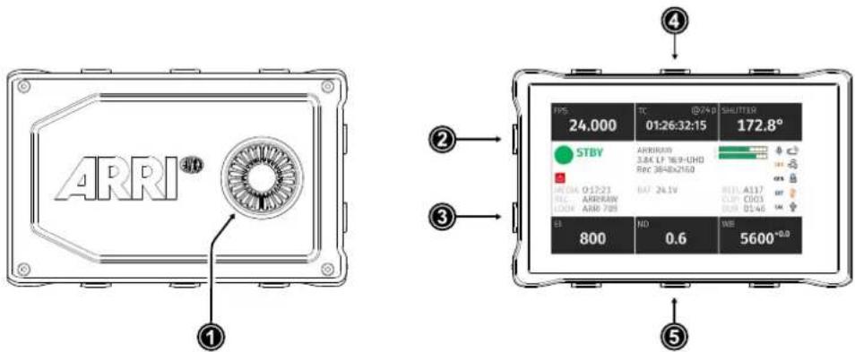
1 JOGWHEEL 2 HOME / LIVE Button
3 MENU / BACK Button
4 Upper Screen Buttons
5 Lower Screen Buttons
JOGWHEEL
The JOGWHEEL (1) is used to
▶ scroll or navigate through lists and menus
▶ change values (by scrolling up or down)
▶ access and confirm settings (by pressing the JOGWHEEL center)
HOME / LIVE Button
The HOME / LIVE button (2) toggles to display either the HOME screen (shown in the image above) or the camera live view.
MENU / BACK Button
Pressing the MENU / BACK button (3) while on the HOME screen or in camera live view opens the camera menu. While in the camera menu, it serves as a BACK button.
Screen Buttons
The MVF-2 flip-out monitor has six screen buttons, three above (4) and three below (5) the screen. Their function depends on the screen content and is labeled directly below or above each button. Unlabeled buttons do not have a function for that screen. A grayed-out label indicates that the function is currently not available.
Adjusting the Flip-out Monitor

natural_image
Line drawings of a digital camera module showing the assembly process (no text or symbols)Fold out, swivel and fold in the monitor to put the display visible in the folded-in position. The image on the monitor automatically adjusts its orientation, or can be set to the desired orientation in the camera menu).
12.2 MVF-2 Cables
The Multi Viewfinder MVF-2 is connected to the camera using an industrial CoaXPress cable. The cable center pin and shield transport power, video, audio and data and the interface allows for hot-plugging the viewfinder. Since the VF connector has no key, the viewfinder cable can be plugged in in any orientation.
ADVICE
When attaching a new viewfinder to the camera for the first time, it may take around 2 minutes until the viewfinder OLED calibration is fully loaded and activated.
Viewfinder Cables
MVF-2 viewfinder cables are available in the following lengths:
| ID No. | Length | Suggested Use |
| K2.0023915 | 0.35 m (1.15 ft) | For use of MVF-2 on camera left side in handheld mode |
| K2.0023943 | 0.5 m (1.5 ft) | For use of MVF-2 with VEB-1 or VEB-3, for use on camera right side |
| K2.0023944 | 2.0 m (6.5 ft) | The medium length for remote use |
| K2.0023945 | 10.0 m (33 ft) | The longest possible length for remote use |
13 Menu Operation
The camera menu has a tree structure and the name of the current submenu is displayed across the top of every screen. To access the menu, press the MENU / BACK button on the MVF-2 or connect to the camera via WiFi or Ethernet and open the "web remote", page 131.
The camera menu consists of 11 submenus:
- Recording
Media - Monitoring
- Look
- System
-
Setup
-
User Buttons
- Metadata
• ECS (Electronic Control System) - Info
- Alerts
Basic Menu Operation

- Press the MENU / BACK button (1) on the MVF-2 to access the camera menu.
- Rotate the JOGWHEEL (3) or the USER WHEEL (5) to scroll up or down to select the desired menu entry:
Entries with a ">" at the end navigate to a submenu. To navigate to a submenu press the JOGWHEEL center or the SET button (4). To return to a higher menu level press the MENU / BACK button.
Entries with a value allow for direct editing. To edit a value press the JOGWHEEL center or SET button, then rotate the JOGWHEEL or USER WHEEL to select the desired value. Press the JOGWHEEL center or SET button to confirm the change or press CANCEL to discard.
Entries with a check box allow for direct activation/deactivation. Press the JOGWHEEL center or SET button to activate/deactivate the setting.
- To leave the menu press the HOME / LIVE button (2).
The JOGWHEEL and the USER WHEEL + SET button provide identical functionality.
13.1 HOME Screen
The HOME screen is the ALEXA Mini LF default screen. It shows the most important camera parameters and gives quick access to changing them through the screen buttons:
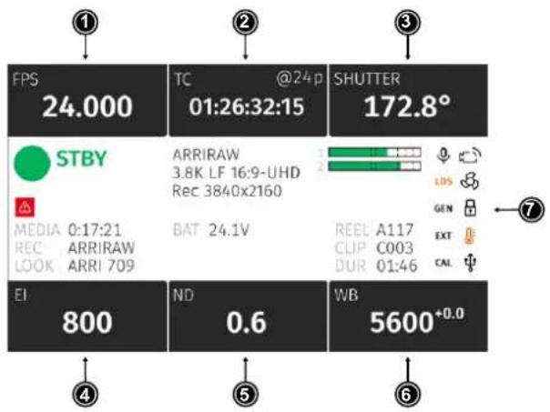
1 FPS Sensor Frame Rate Settings
2 TC Timecode Settings
3 SHUTTER Settings
4 EI Exposure Index Settings
5 ND Filter Settings
6 WB White Balance Settings
7 Status Section
FPS (Sensor Frame Rate)
The FPS label shows the current sensor frame rate in frames per second. Press the FPS screen button to adjust the sensor frame rate. The FPS label turns orange if the sensor fps does not match the project fps rate.
Note: The maximum frame rate that can be set is dependent on the recording resolution and the codec.
TC (Timecode)
The TC label shows the current timecode value and project rate. Press the TC screen button to access the timecode settings. The TC label turns orange if a timecode misconfiguration persists, press the TC screen button for more information.
SHUTTER
The SHUTTER label shows the current shutter angle or exposure time. Press the screen button to set the shutter of the sensor. Shutter angle and sensor FPS determine exposure time of the sensor in seconds by the following equation: angle / (360° * FPS). The shutter unit can be set to display either shutter angle (5.0° to 356.0°) or exposure time (1 s to 1/8000 s). The maximum shutter angle is limited by the resulting exposure time (1 s max.).
EI (Exposure Index)
Shows the current exposure index. Base sensitivity for the ALEXA Mini LF is 800 ASA. Press the screen button to adjust the exposure index in a range from 160 to 3200 ASA.
ND Filter
The ND label shows the current ND filter value of the in-camera FSND (Full Spectrum Neutral Density) filter stage. Press the screen button to change the ND filter.
WB (White Balance)
The WB label shows the current white balance and tint. Press the screen button to set the camera's white balance. This is the color temperature of the light source that the camera is currently adjusted for. In addition to the red/blue correction of the white balance, the ALEXA Mini LF can also compensate for a green/magenta tint. This value, called CC (color compensation), is shown as an exponent of the WB value. Positive values are marked with a "+" and negative values with a "-"
White balance can be adjusted from 2,000 to 11,000 Kelvin (here: 5,600) in steps of 10 K for red/blue correction. Color compensation for green/magenta tints can be adjusted in a range from -16.0 to +16.0. Positive or negative CC color compensation values then appear as an exponent of the WB value (here: +0.0).
Status Section
The status section on the home screen shows key data about recording, power supply, remaining media capacity and more:
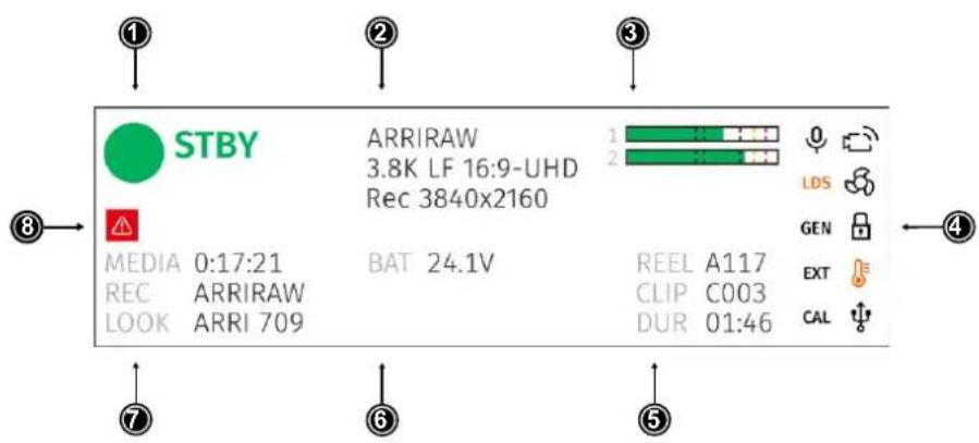
1 Camera Status 5 Clip Information
2 Codec & Recording Resolution 6 Battery Level
3 Audio Meters 7 Media Capacity & Look Setting
4 Status Icons 8 Camera Alert Icon

STBY
Camera Status
STBY Standby - ready for recording.
REC Recording.
PLAY Camera is in playback mode.
ERASE Medium erase in progress. Active erasing disables recording.
None Idle, recording not possible (e.g. no media inserted, media is full).
ERROR System error occurred. See MENU > Alerts for details.
ARRIRAW
3.8K LF 16:9-UHD
Rec 3840x2160
Codec & Recording Resolution
Currently active codec and recording resolution.
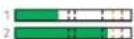
Audio Meters
The audio meters are only displayed if audio recording is enabled and show the current level of audio channels 1 & 2. If audio recording is disabled, a crossed out speaker icon is displayed.
Black markers are shown at signal levels -20, -18, -9 dBFS for reference test tone. The yellow marker at -5 dBFS and the red marker at -2 dBFS indicate a signal close to clipping. A red frame around the meter indicates a clipping at the A/D stage.
REEL A117
CLIP C003
DUR 01:46
Clip Information
REEL Current reel (camera index letter and reel number)
CLIP Name of current clip of current reel.
DUR Duration of currently recorded clip (during REC) or last recorded clip (during STBY).
BAT 24.1V
Battery Level
Current battery voltage level.
MEDIA 0:17:21
REC ARRIRAW
LOOK ARRI 709
Media Capacity & Look Settings
MEDIA Remaining capacity of the recording media, at current FPS and codec combination, in real time. When media capacity is below 2 minutes, capacity values start flashing.
REC Active recording processing (ARRIRAW or Log C)
LOOK Active Look
Status Icons

WiFi Icon. WiFi is enabled and the WiFi mode is set to Host

WiFi Icon. WiFi mode Client is enabled and the camera is connected to a network.

WiFi Icon. WiFi mode Client is enabled but the camera is not connected to a network.

Sensor Temperature Icon
Black Sensor temperature warning Orange Sensor temperature error Red System temperature error (see MENU > Info > System Info)

Fan Speed Icon
Black Fan speed about to increase above 20 dB. Orange Fan speed is higher than 20 dB.

USB Icon
Black USB medium ready. Gray USB medium is read only. Orange USB medium is not usable.

Frame Grab Icon
Black Frame grab is active. Orange Frame grab failed.

Camera Lock Icon. Camera buttons are locked.

MVF-2 Lock Icon. MVF-2 buttons are locked.

Audio Icon. Audio recording is enabled.

Audio Icon. Audio recording is disabled.

Audio Icon. Internal microphones are enabled.

MVF-2 eyepiece heater is active.
| Black | Eyepiece heater is active. |
| Gray | Eyepiece heater is not heating (eyepiece temperature is >15 °C (59 °F)). |

Genlock Icon
| Black | Camera is synchronized to genlock source. |
| Orange | Camera is not synchronized to genlock source (signal not present or unusable). |

EXT Sync Icon
| Black | EXT sync active. |
| Orange | Mismatch in EXT Sync configuration. See MENU >Alerts for more information. |

Camera white radio is active.

Lens Motor Icon
| Orange | Lens motor calibration required. |
| Black | Lens motor calibration in progress. |

Indicates an error on the LDS interface.

Alert Icon. Alert is active. See MENU > Alerts for details.
13.2 Using the On-screen Keyboard
When working with textual parameters on the camera, an on-screen keyboard allows entering text. You can use the keyboard, for example, to enter the name of a user setup.
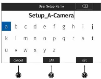
▶ Use the JOGWHEEL to select and confirm characters.
▶ Use the CLEAR button (top right) to delete the character to the left of the cursor. Push the button and hold it to clear the entire text.
▶ The aA# button (2) toggles between lower case, upper case and numeric text entry.
▶ Press the SET button (3) to save the entry.
▶ Press the CANCEL button (1) to discard the entry and exit.
13.3 Working with Lists and Importing Files
For certain parameters, the camera menu operates with preset lists that come with a default content and that can be adjusted to the user's preference. You can add values to and delete values from these lists, so that only project relevant values are displayed. Value based lists contain entries that can be edited directly in the camera (e.g. Shutter and White Balance presets) while file based lists contain files that are installed on the camera or were imported from the USB medium (e.g. Looks and Frame Lines)
Following parameters work with value based lists:
HOME > FPS
HOME > SHUTTER
HOME > WB
Following parameters work with file based lists:
■ MENU > Look > Look
■ MENU > Monitoring > Frame Lines > Frame Line
■ MENU > Setups > User Setups Installed
■ MENU > ECS > Lens Data > Lens Tables Installed
Adding Entries to Value based Lists
The camera offers two methods of input when adding entries to a list. The numeric keyboard is intended to be used for direct input of a value while the jogwheel mode is intended to be used for fine tuning a value (for example to fine adjust the shutter when filming monitors). The minimum and maximum possible values are shown in the middle of the screen above the horizontal line.
▶ Select e.g. HOME > FPS > ADD.
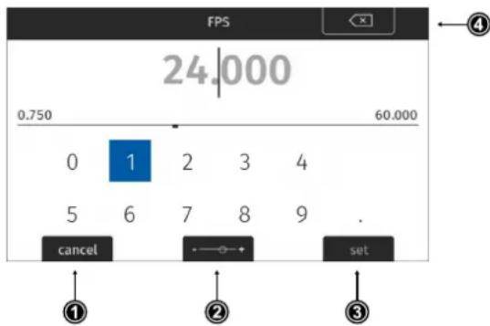
▶ Press the MODE button (2) to switch between the numeric keyboard and the jog-wheel mode.
The numeric keyboard offers to directly enter a value. Use the MVF-2 jogwheel to select and confirm digits.
▶ The CLEAR button (4) deletes the digit to the left of the cursor. Press and hold the button to clear the entire value.
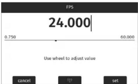
▶ The jogwheel mode allows to fine adjust values. Rotate the MVF-2 jogwheel to fine tune the value.
▶ Press the MODE button (2) to if you need to switch back to the numeric keyboard.
▶ Press the SET button (3) to add the new value to the presets list, or the CANCEL button (1) to exit. Info: the SET button will be grayed out and the value displayed in red if the entered value is out of range.
Importing Files
For looks, frame lines, user setups and lens tables the camera offers the option to import files from the USB medium as well as from a factory default presets. To import files from a USB medium into the camera, the USB medium needs to be prepared with a certain folder structure, see chapter "User
Storage Handling", page 50 for more information. The maximum file name length allowed is 64 characters including the file extension. Files with a name exceeding 64 characters cannot be displayed in camera lists. Special characters <, >, :, ", /,\, | and * in file names are displayed and replaced with a "?" in the camera menu.
▶ Select e.g. MENU > Monitoring > Frame Lines > Frame Line > ADD.
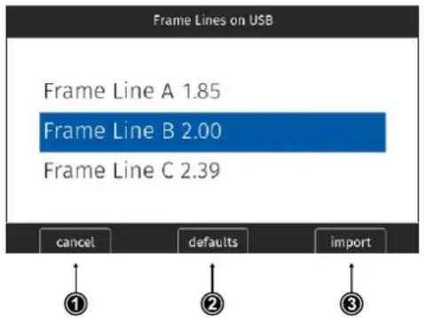
▶ Select a frame line file to import from the USB list or select DEFAULTS (2) to select a frame line file from the factory defaults list.
▶ Press the IMPORT button (3) or the jog-wheel to add the selected frame line to the frame lines list, or the CANCEL button (1) to exit.
Deleting List Entries
▶ Select e.g. HOME > FPS.
▶ Scroll to the entry to be deleted.
▶ Press the DELETE button.
The selected entry is marked for delete.
▶ Press the DELETE button again to delete the selected entry or rotate the jogwheel to cancel.
Maximum Entries per List
All lists have a maximum number of entries they can hold. Whenever a list is full, the ADD button is grayed out and a message is shown. You need to delete entries from the list first in order to add new ones.
The following table lists the maximum number of entries for each type of list:
| List | FPS, Shutter | User Setups | White Balance | Looks | LDA | Frame Lines |
| Max. Entries | 16 | 20 | 32 | 50 | 200 | 256 |
13.4 Function Button FN
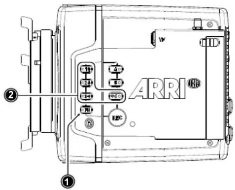
The camera's left side is equipped with the function button FN (1) and six camera buttons of which four are labelled with additional icons (2). These four buttons can act as regular user buttons or in combination with the FN button access common camera functions.
Camera Buttons to Access Common Camera Functions
By default, the camera buttons function as user buttons. In combination with the FN button they offer shortcuts to common camera functions.
Following camera functions can be accessed:
| Function Button & Camera Button | Function | |
| FN+1 | Toggles the overlay menu in the viewfinder and the SDI outputs. In the overlay menu, the camera buttons control the following functions: | |
| Camera Button Function | ||
| 1 Select backward | ||
| 2 Select forward | ||
| 3 Access / Confirm | ||
| For more information, see . | ||
| FN+2 | Prepares recording media erase and shows a message on MVF, flip-out monitor and SDI outputs. To confirm the erase, press camera button 3 twice. Any other button can be pressed to cancel the action. After the erase has finished, press any button to clear the status message. | |
| FN+3 | Starts/stops playback from the recording medium. During playback, the camera buttons control the following functions: | |
| Camera Button Function | ||
| 1 Skip backward | ||
| 2 Skip forward | ||
| 3 Play / Pause | ||
| FN+6 | Toggles WiFi on/off.When pressing (just) the FN button, the status LED of button 6 reflects the current WiFi status (LED on = WiFi enabled). | |
▶ Press and hold the FN button (1), then press a camera button (2) to access the function. You can also press the FN button twice within 0.5 seconds to bring the camera buttons into FN selection mode for two seconds. During these two seconds the FN button status LED is lit (indicating active FN selection mode) and pressing a camera button will access the function behind it.
13.5 User Storage Handling
The ALEXA Mini LF saves data such as user setups, frame grabs and system logs to a USB memory stick. Firmware, additional frame lines and ARRI Look File 2 files can be loaded onto the camera using the USB memory stick.
The camera only supports FAT 32 formatted USB memory sticks using one partition within a Master Boot Record (MBR) partition table and a maximum capacity of 256 GB. A special folder structure is used in order to work with the camera. This folder structure can be prepared in camera and the folder preparation will not alter existing folders and files on the USB medium.
The USB slot is located at the back of the camera below the recording media slot. To access the USB slot, open the media door.
User Storage Status on HOME screen and in Camera Menu
The USB icon in the Status Section on the HOME screen of the user interface reflects the USB medium status:

Black: usable
Gray: read only
Orange: not usable
Prepare User Storage for Use
The camera can only load files from a correctly prepared USB medium with the required folder structure. Preparing the folder structure on the USB medium within the camera will not alter existing folders and files on the USB medium.
- Open the media door and insert the USB medium.
- Select MENU > Media > Prepare USB Medium.
- Press CONFIRM to prepare the folder structure.
The USB memory stick is now ready for use with the camera.
The required folder structure for use in the camera is listed below, and can also be created manually on a computer:
| ARRI/A-MINI-LF/ FRAMELINES | for frame line imports to camera |
| GRABS | for grabbed still frames |
| LDA | for lens tables imports/exports |
| LICENSES | for license file installation |
| LOG | for exported camera and update logfiles |
| LOOKFILES | for look file imports/exports |
| SETUPS | for imports/exports of user setup files |
| SUP | for update file installation |
| SENSOR | for import/export of User Pixel Mask files and export of frame grabs for User Pixel Mask creation |
Remove User Storage
You can remove the USB medium from the camera without needing to unload it.
13.6 Info Screens
The INFO screens provide detailed information about the current state of the camera system.
▶ Select MENU > Info.
The INFO list contains the following entries.
- Version Info
- System Info
• Maximum FPS Info
• Media Info - USB Info
- Network Info
- Lens Info
- User Button Info
- EXT Sync Info
- Export HW Info File
- Export Logfiles
- Export Update Logfiles
Version Info
The version info screen displays the software versions of the camera and connected components:
| Software | The camera software version. |
| Revision | Revision of camera software version. |
| FPGA | Firmware version of active FPGA (indicated by number in brackets). |
| MVF-2 Software | Software version of MVF-2 (only shown if connected). |
| Lens Mount Software | Software version of lens mount. |
System Info
The system info provides detailed information about the camera:
| Time + Date | Current system time and date of the camera. |
| Camera Serial No. | Serial number of camera. |
| Operating Hours | Total operational time of the camera in hours:minutes. |
| Sensor Temperature | Current temperature of image sensor. |
| Sensor Temp. State | Rates the sensor temperature according to OK, warning, or error. |
| Camera Temp. State | Rates the camera temperature according to OK, warning, or error. |
Maximum FPS Info
This screen gives detailed information about the maximum sensor frame rate:
| Sensor FPS | Maximum sensor FPS with the current recording resolution. |
| Codec FPS | Maximum sensor FPS with the camera's current codec setting. |
| Media FPS | Maximum sensor FPS supported by the inserted recording media with the current recording codec and camera's resolution setting. |
Media Info
This screen shows information on the recording media:
| Status | Status of the recording media. |
| Model | Name/model of the recording media. |
| SN# | Serial number of the recording media. |
| FW Version | Firmware version of the recording media. |
| Size | Total storage size of the recording media. |
| Clip Count | Amount of clips on the recording media. |
USB Info
This screen shows information on the USB storage. The number entries consist of two numbers, the number of files on the USB medium and the number of files recognizable by the camera.
| Status | Status of USB medium. |
| Storage Free/Total | Free and total available storage on USB medium in megabyte. |
| Frame Line Files | Number of frame line files on USB medium. |
| License Files | Number of license files on USB medium. |
| Look Files | Number of look files on USB medium. |
| Setup Files | Number of user setup files on USB medium. |
| SUP Files | Number of SUP (software update package) files on USB medium. |
| LDA Files | Number of LDA (Lens Data Archive) files on USB medium. |
Network Info
The network info screen shows Ethernet and WiFi related information:
| WiFi Network | Name of connected network (client mode). |
| WiFi IP | IP address of the camera via WiFi. |
| LAN IP | IP address of the camera via Ethernet. |
| Web Remote | URL address of camera remote control website. |
Lens Info
The lens info screen shows information on the attached lens:
| Lens Type | Type of lens (LDS, Cooke, ENG, EF...) |
| Model | Lens model name according to manufacturer. |
| Serial No. | Serial number of lens. |
| Extender | Name of extender (if used). |
| Focal Length | (Current) focal length of lens in mm. |
| Focus | Current focus distance of lens. |
| Iris | Current iris value of lens. |
User Button Info
The user button info screen lists the functions assigned to the User Buttons of the camera body and the MVF-2.
EXT Sync Info
The EXT Sync info screen shows the system status of all cameras in the EXT sync setup. It lists the serial number, the camera ID prefix, the battery voltage and the status of the master and the slave camera(s) in the setup.
Export HW Info File
HW (Hardware) info files are required to generate licenses in the ARRI License Shop or may be requested by camera service to get detailed information on the camera's hardware and components.
The HW Info file will be exported to the USB medium in the ARRI/A-MINI-LF/LICENSES folder.
Export Logfiles
Logfiles help ARRI camera service to analyze potential problems. In normal circumstances, logfile export is not required.
Export Logfiles combines the camera logfiles, HW Info file, current user setup and other diagnostic files into a .zip archive and stores the archive in the ARRI/A-MINI-LF/LOG folder.
Privacy sensitive information such as WiFi password and look files are not exported.
Export Update Logfiles
Similar to regular logfiles, update logfiles help camera service to analyze problems that occurred during the update process. In normal circumstances, exporting update logfiles is not required.
Update logfiles will be exported to the USB medium in the ARRI/A-MINI-LF/LOG folder.
13.7 Alerts Screen
Alert messages communicate critical system states to the user. They require immediate attention and remain active until the state returns to normal.

A red exclamation mark, visible on the home screen, the flip-out monitor and the EVF and SDI status overlays indicates active alert messages.
▶ Select MENU > Alerts to read the alert message.
14 Main Parameters
The following chapter lists the most important parameters of the camera.
14.1 Project Settings
The project settings menu contains settings that should be configured at the beginning of each project and can be found at MENU > Recording > Project Settings.
Project Rate
The project rate sets the timecode timebase and the playback frame rate. The timecode timebase determines how many frames the timecode counts per second. The playback frame rate determines the frame rate at which clips will be played back.
Changing the project frame rate will automatically change the sensor frame rate and the SDI frame rates to the same value. It is still possible to have different frame rates for these settings by changing the sensor frame rate or the any of the SDI frame rates individually.
- Select MENU > Recording > Project Settings > Project Rate.
The following project rates are available:
| Project Rate | Scan Format | Sensor Real-time Recording |
| 23.976p | Progressive | 23.976 fps |
| 24p | Progressive | 24 fps |
| 25p | Progressive | 25 fps |
| 29.97p | Progressive | 29.97 fps |
| 30p | Progressive | 30 fps |
| 48p | Progressive | 48 fps |
| 50p | Progressive | 50 fps |
| 59.94p | Progressive | 59.94 fps |
| 60p | Progressive | 60 fps |
- Set the desired project rate.
Changing the project rate will match sensor and SDI fps setting to the project rate. A pop up window will inform you about this.
Next Reel Count
The next reel count sets the reel number assigned to the next new media used for internal recording. A new media is either a blank media or a media with reels of other ALEXA Mini LF cameras. The camera automatically advances the reel number every time new media is formatted on the camera. The reel number is reflected in clip names and is displayed on the home screen.
-
Select MENU > Recording > Project Settings > Next Reel Count.
-
Set the desired next reel count.
Camera Index
Give each camera a unique camera index so that you can identify the individual camera unit (A, B, C etc.) in clip and reel names. For more information please see "File Naming Scheme", page 79.
- Select MENU > Recording > Project Settings > Camera Index.
- Set the camera index in the range from A to Z.
Camera Index Color
Set the color of the camera index letter displayed in the status info of the SDI outputs (e.g. to match it to the color coding of your cameras).
- Select MENU > Monitoring > SDI > SDI Processing > Overlays > Status Components > Camera Index Letter to display the camera index letter in the SDI status info.
- Select MENU > Recording > Project Settings > Camera Index Color.
- Set the camera index color.
Camera ID Prefix
You can define the first character of the Camera ID. The Camera ID is a Base36 representation of the camera serial number and part of each clip's name. It allows you to match each clip to a specific camera. You set the camera ID prefix individually on each camera. For more information please see "File Naming Scheme", page 79.
- Select MENU > Recording > Project Settings > Camera ID Prefix.
- Set the camera ID prefix in the range from A to Z.
Lens Squeeze Factor
The lens squeeze factor determines the factor that is used for anamorphic desqueeze on EVF/Monitor and SDI. This value is also written into the metadata of the clip and allows video players and editing software to automatically desqueeze clips that have been shot with anamorphic lenses.
- Select MENU > Recording > Project Settings > Lens Squeeze Factor.
The following lens squeeze factors are available:
| Factor | Usage |
| 1.00 | for all spherical lenses |
| 1.25 | e.g. Ultra Panavision 70 Lenses |
| 1.30 | e.g. Vantage Hawk Lenses |
| 1.50 | e.g. P+S Technovision, Iscorama, Kowa |
| 1.65 | e.g. Panavision Ultra Vista Anamorphic lenses |
| 1.80 | e.g. Cooke Anamorphic/i Full Frame Plus lenses |
| 2.00 | for classic 2x squeeze CinemaScope S35 lenses |
- Set the desired lens squeeze factor.
The selected lens squeeze factor is automatically applied to EVF/Monitor and the SDI outputs.
For more information please see "Anamorphic Desqueeze", page 93.
14.2 Sensor Frame Rate
Setting the Sensor Frame Rate
- Select HOME > FPS.
The sensor FPS list is displayed.
- Select a frame rate from the FPS list or add and select a custom frame rate.
The sensor fps list is displayed.
-
Using the jogwheel, scroll to the desired value/entry.
-
Press the jogwheel to set the new value.
14.3 Shutter
Changing the Shutter
- Select HOME > SHUTTER.
The shutter list is displayed.
-
Select a shutter value from the list or ADD a custom shutter value to the list.
-
Set the desired shutter value.
Adjusting the Shutter for Filming a Monitor
- Set the shutter unit to Shutter Angle.
- Go to HOME > SHUTTER > ADD.
- Select the third digit (single degrees).
- Adjust the shutter value until the monitor image flickers the least.
- Select the fourth digit (sub-degrees).
- Fine-adjust the shutter value until there is no more flicker visible.
- Press SET to add the shutter value to the list.
Shutter Unit
The camera offers to set the shutter unit.
- Select MENU > System > Shutter Unit.
Two options are available:
Shutter Angle Converts exposure time into the angle of a virtual rotating mirror shutter as in film cameras. A fixed angle creates varying exposure times with varying frame rates. You can set angles from 5.0 to 356.0 degrees.
Exposure Time Shows the effective sensor exposure time. With varying frame rates, it remains identical and can be set from 1/1 to 1/8000 seconds.
Note: Maximum exposure time with a given frame rate is 1/fps, with a limit of 1/1 seconds. When the selected exposure time is no longer possible because you changed the frame rate, the camera uses the longest exposure time possible. For example, if you configured 1/25 s at 25 fps and you change the sensor fps to 50, the camera will use 1/50 s.
For a constant exposure time over a range of used frame rates, set it to 1/(highest used frame rate).
- Set the desired shutter unit.
Note: The camera sensor is optimized for exposure times shorter than 1/24 s and image artifacts like individual overexposed pixels can appear when using longer exposure times.
14.4 Exposure Index
The Exposure Index (EI) is the applied sensitivity of the camera. The ALEXA Mini LF has a base sensitivity of 800 ASA. This means that the dynamic range is almost evenly distributed above and below neutral gray with low noise in the shadows and clean, smooth clipping behavior in the highlights. Due to its high dynamic range, the camera's sensitivity can be set from 160 to 3200 ASA in steps of 1/3 stops while maintaining high image quality.
Applying the exposure indexes at the extremes of the range will nonetheless have an influence on the images. At low exposure indexes, such as 160 ASA, the dynamic range below neutral gray increases, reducing noise even further. At the same time, the dynamic range above neutral gray is slightly reduced. Highlight clipping itself is not influenced by this, but the shoulder of the gamma curve will get slightly steeper, reducing the smoothness of the change from almost overexposed to overexposed. At high exposure indexes, such as 1600 ASA, the images behave in the opposite way. Noise is increased, which makes it important to judge shadow detail, while there will be even more headroom in the highlights.
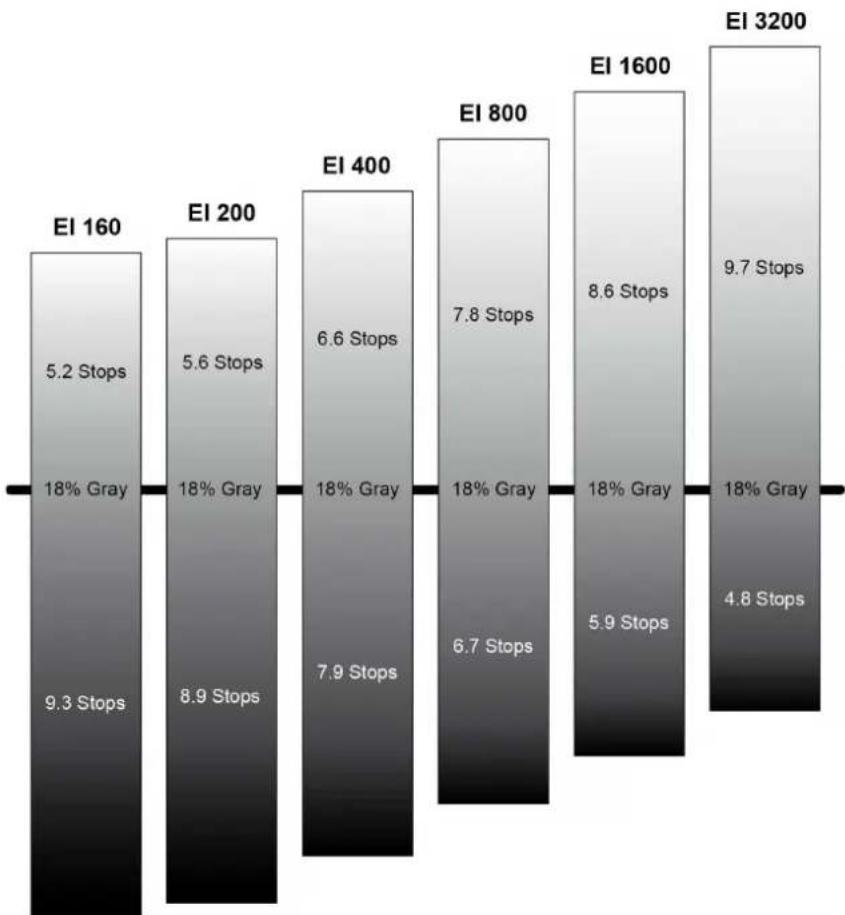
bar
| EI | Number of Stops | Percentage (%) | | :--- | :--- | :--- | | EI 160 | 5.2 | 18% Gray | | EI 200 | 5.6 | 18% Gray | | EI 400 | 6.6 | 18% Gray | | EI 800 | 7.8 | 18% Gray | | EI 1600 | 8.6 | 18% Gray | | EI 3200 | 9.7 | 18% Gray | | EI 160 | 9.3 | Stops | | EI 200 | 8.9 | Stops | | EI 400 | 7.9 | Stops | | EI 800 | 6.7 | Stops | | EI 1600 | 5.9 | Stops | | EI 3200 | 4.8 | Stops |Setting the Exposure Index
- Select HOME > EI.
- Set the desired exposure index.
ADVICE
When changing the EI setting, short temporary artefacts may appear on the image outputs resulting from the change.
When changing the EI setting during recording, one or more frames on the recorded material may show artifacts resulting from the change.
14.4.1 EF Lens Iris Adjustment
- Select HOME > EI > Iris.
A screen showing the current iris value is displayed.
- Turn the jogwheel up or down to open or close the iris. Press the jogwheel to toggle between full stops and substops.
Note: Sub-stop precision depends on the lens type and is automatically set by the camera.
14.5 ND Filter
Internal FSND Filters
The ALEXA Mini LF has a built-in motorized and sealed filter stage for Full Spectrum Neutral Density filters (FSND) with densities of 0.6, 1.2 and 1.8 (and an optical clear filter). In comparison to IRND filters, which have an uneven spectral behavior, or to an ordinary ND filter, which opens up at about 675 nm, the FSND filters offer a true, even reduction over the whole spectrum. This prevents artifacts from infrared wavelengths and the need for additional IR filters.
Selecting the ND Filter
The currently set ND filter value is displayed on the HOME screen and in the status info of the viewfinder and the SDI outputs. The camera offers various ways to adjust the ND filter:
ND Filter screen
▶ Camera user buttons
▶ WCU-4 user buttons
ARRI Master Grips and Operator Control Unit OCU-1 user buttons
▶ Web remote
Applications communicating with the camera through the Camera Access Protocol (CAP).
Selection in camera menu
- Select HOME > EI > ND.
Following settings are available:
ND - (Clear)
ND 0.6
ND 1.2
ND 1.8
- Set the desired ND filter.
14.6 White Balance
White Balance (WB) is the color balance of the camera that should be matched to the color temperature of the light in use. White balance is a red-blue adjustment of the image. To adjust the green-magenta balance, use the color compensation (CC) adjustment. For example, a fluorescent source will have peaks in its spectrum that cannot be corrected with red-blue white balance alone. The CC shift can correct these peaks up to a full green or full magenta gel. One step of CC shift is equal to 035 Kodak CC values or 1/8 Rosco values.
There are three methods for setting the white balance:
▶ White balance presets
▶ Custom white balance
▶ Automatic white balance
Preset and Custom White Balance
- Select HOME > WB.
The WB list is displayed, offering the following default values:
3200 K +0.0 CC
4300 K +0.0 CC
5600 K +0.0 CC
7000 K +0.0 CC
- Select a value from the list or ADD and select a custom white balance.
For information on how to add entries to a list please see "Working with Lists and Import of Files".
Automatic White Balance
Automatic white balance calculates the white balance based on the camera's live image and overwrites the active white balance value. The result is stored as first entry in the WB list. Automatic white balance can be triggered through a dedicated button in the white balance screen or through a user button assigned with Auto WB. For information on how to assign functions to user buttons please see "User Buttons", page 121.
- Select HOME > WB.
- Press Auto WB.
The EVF and the SDI outs display an image overlay showing the center area used for white balance calculation.
- Press the Auto WB button again within one second to execute automatic white balance.
The calculated white balance is set and stored as first entry in the white balance list.
Note: Under- or overexposed images may cause the automatic white balance to fail. Always trigger automatic white balance with properly exposed images.
14.7 Timecode
Timecode ensures that every image of recorded footage can be identified with a unique value and synced with corresponding media, such as sound or the second camera in a 3D application. When used with other metadata, such as reel names, all recorded media retains its unique identity.
The following are two ways of using timecode on a production:
Free Run Timecode, Time of Day
Use: This format is often used on multi camera productions with sync-sound, i. e. the sensor frame rate matches the project rate, sound and image timecode match and allow for easy syncing in post.
Setup: The sound department acts as the timecode master, and generates timecode which uses the time of day as a value, and a time base matching the project frame rate. Twenty-four hours of time will translate into twenty-four hours of timecode. Timecode is fed to the camera via the TC connector. The project fps setting must match both the sensor frame rate and the time base of the external timecode signal.
The camera can be set to timecode mode jam sync, in which it samples the timecode value once from the timecode connector and then continues counting based on its own high precision crystal clock. The timecode source can be disconnected from the camera after jamming in jam sync mode. This mode ensures stable timecode with an offset of less than one frame for each eight hours, after which the camera has to be re-jammed.
Alternatively, the camera can be set to timecode mode regenerate (regen). In regen mode, the camera uses the timecode value of the external timecode source. This ensures correct timecode for an infinite duration, but the timecode source must remain connected to the camera. Please note that while recording the camera ignores external timecode and is using its internal clock to avoid potential timecode jumps, which can occur due to connection problems such as a faulty timecode cable for example.
Variations: If shooting starts close to midnight, the timecode may be started with an offset time of day to prevent a rollover at midnight.
Restrictions: Free run timecode is only possible, if the camera is running at sync-sound speed. If the camera is over- or undercranking, the timecode frame rate will no longer match the sensor frame rate, and timecode values would either be duplicated or dropped. To prevent this, the camera will automatically switch to run mode rec run when the sensor frame rate is changed.
Rec Run Timecode
Use: Rec run timecode is often used on single camera productions that are either MOS or use a dumb slate to sync picture and sound. Record run timecode guarantees continuous timecode on all recorded data. Record run timecode also works with over- and undercranking.
Setup: The timecode run mode must be set to rec run, the mode to regenerate. Timecode counts up only during recording, by one frame for each image generated by the sensor. The timecode counts at the project frame rate set on the camera. Normally, the timecode hour value advances by one hour for each new reel, using only hours 01-20 for reel 1-20, and then restarting at hour 01 for reel 21.
Variations: Rec run timecode might be used for off-speed work on productions that use external timecode sources for all sync sound.
Restrictions: None
Setting the Timecode Manually
- Select HOME > TC > Options > Timecode to set the timecode manually.
- Select HOME > TC > Options > Reset Timecode to reset the timecode to 00:00:00:00.
- Select HOME > TC > Options > Set Timecode to Time to set the timecode to the camera system time.
Note: You can edit timecode in preset mode only.
Timecode Run Mode
- Select HOME > TC > Options > Run Mode.
You have the following options:
Rec Run Timecode increases during recording only. The timecode value increases with every frame generated by the sensor while recording.
Free Run Timecode increases with every new frame generated by the sensor, independently from recording.
Note: Free run is only possible if the sensor fps equals the project fps (i.e. shooting sync speed). Otherwise, the camera temporarily switches to rec run. The free run timecode continues to count in the background.
When you set the sensor frame rate back to equal the project frame rate, the timecode will synchronize itself to the free run timecode again.
If you synchronized your camera to an external signal while it was in free run, you can shoot offspeed shots in rec run timecode and return to sync speed afterwards. The camera will return to free run timecode and seamlessly reconnect to the previously synchronized timecode.
Timecode Mode
▶ Select HOME > TC > Options > Mode.
You have the following options:
Regen Depending on the timecode run mode, regen behaves differently:
Run mode rec run: The camera determines the timecode of the last frame of the last recorded clip and increments it by one for the next clip. This ensures consecutive timecodes for a sequence of clips.
Run mode free run: The timecode source should be connected to the camera permanently. The camera continuously reads the timecode signal at the timecode connector as long as it is present. Upon disconnection or loss of signal, the camera continues counting on its own, but will indicate the missing signal through an orange exclamation mark on the TC button on the home screen.
When the external signal is reconnected, the camera uses the value of the external signal again. Regen mode will disable manual editing of the timecode.
Preset The camera uses its internal counter.
Jam Sync The camera samples the timecode value and simultaneously tunes its inter-
nal timecode clock to match the clock of the timecode source. During this procedure, the timecode display on the home screen, on the timecode menu screen as well as on the status overlays is flashing. Jamming has finished when the timecode display stops flashing, then the timecode source can be disconnected. The camera continues counting based on its own high precision crystal clock now. This mode ensures stable timecode with a drift of less than one frame over eight hours, after which the camera has to be re-jammed.
Note: Due to the tuning mechanism, jamming the camera might take up to 30 seconds and a timeout is issued if tuning could not be completed after 60 seconds.
Regen Source
Based on the timecode run mode, the camera determines the timecode regen (regenerate) source automatically. If the run mode is set to Free run, it regenerates timecode from the timecode input connector. If set to Rec run, it regenerates timecode from the last clip of the recording media by continuing seamlessly from the last active value.
▶ View HOME > TC > Options > Regen Source.
The regen source is displayed. The following settings are possible:
LTC In timecode is continuously read from the TC connector.
Media timecode from the last clip of the active recording card by continuing seamlessly from the last active value.
EXT when camera is set to EXT sensor slave or EXT settings slave)
Timecode Count Mode
Sets the preference for how timecode is counted with non-integer project rates (29.97p, 59.94p) Note: The setting Count Mode is only accessible when the project rate is set to a non-integer frame rate.
▶ Select HOME > TC > Options > Count Mode.
You have the following options:
Non-Dropframe Timecode increases with every frame without compensation, resulting in a 1,001 count for 1,000 frames.
Dropframe Timecode values are dropped with a defined pattern (frame counts 00 and 01 of every minute, except every 10th minute) to re-adjust for the drift. A semi-colon between timecode seconds and frames indicates an active dropframe timecode.
Timecode Offset
You can apply an offset to LTC input signals to compensate for timecode offsets in external devices.
- Select HOME > TC > Options > TC Offset.
- Adjust the timecode offset in the range of -20 to +20 frames.
ADVICE
The camera's internal battery will keep the timecode and timecode tuning values for about 5 minutes after the power source was disconnected.
15 Look Settings
ARRI Look File 2
ARRI Look File 2 files are a way for the user to alter the parameters the camera uses when converting the sensor image data to a video color space. This can be described as applying a custom "look" to the different image output paths. With the ALEXA Mini LF the ARRI Look File 2 files can be applied to the monitoring paths and is included in the clip as metadata only (nondestructive workflow).
The ARRI Look File 2 can influence an image, respectively a shot or scene. For a good overview of the color controls, follow the image path of the camera in the scheme below: In the first step the sensor data is balanced for the light source's color temperature (white balance). This ensures a neutral representation of the R, G, and B values of objects. In the second step, a Log C image is created. The Log C transform is controlled by the exposure index (EI), which is (like the white balance) not part of the look. All following alternations to the color are based on a Log C image which is also the result if the whole look mechanism is bypassed.
Inside an ALF-2 file, various combinations are possible:
• Color Decision List (CDL) only
• CDL and Video Look Parameters
- CDL and 3D LUT
• 3D LUT only (e.g. conversion to REC 709 or custom LUT)
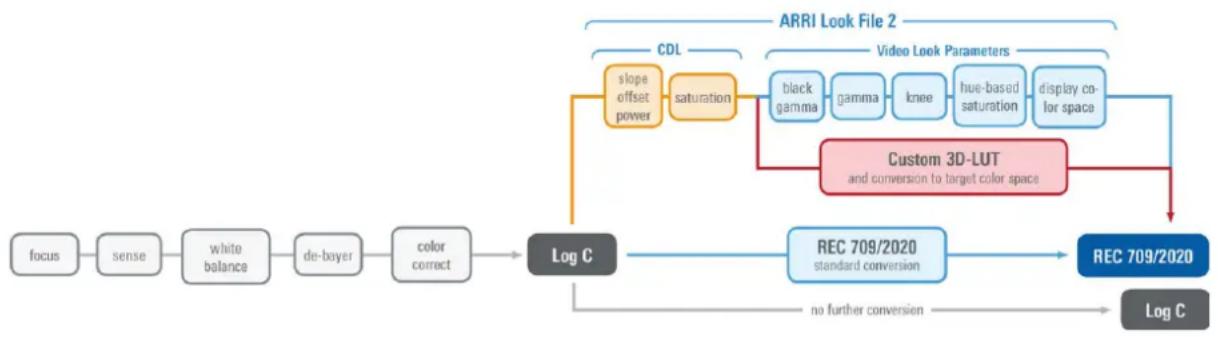
flowchart
graph LR
    A["focus"] --> B["sense"]
    B --> C["white balance"]
    C --> D["de-bayer"]
    D --> E["color correct"]
    E --> F["Log C"]
    F --> G["REC 709/2020 standard conversion"]
    G --> H["REC 709/2020"]
    H --> I["Log C"]

    subgraph ARRI Look File 2
        J["slope offset power"] --> K["saturation"]
        K --> L["CDL"]
        L --> M["Video Look Parameters"]
        M --> N["Custom 3D-LUT and conversion to target color space"]
    end

    J --> K
    K --> M
    M --> N
    N --> H
    style ARRI Look File 2 fill:#f9f9f9,stroke:#333
    style ARRI Look File 2 fill:#e6f7ff,stroke:#333
A look file can be created in the ARRI Color Tool as a completely new look, using a 3D LUT created in a grading session or you can edit the look live on set using a live-grading application like Filmlight Prelight or Pomfort Livegrade. For a more detailed look at a specific live-grade workflow, please visit the manufacturer website.
These tools connect to the camera's look controls via the Camera Access Protocol (CAP). The current look is recorded as metadata with the push of the record-button and rewritten with its latest values when the recording is stopped, and the file closed. This guarantees to have the latest “starting look” if a power-out interrupts the recording and to keep the subtle changes done during the take.
After recording, backup and data transfer, the look can be extracted from the clip's file header using the ARRI Color Tool again. This way the look can travel to post production as an ARRI Look File 2 or as a 3D LUT.
For more information about the ARRI Look File 2, please refer to the ARRI Look File 2 white papers, available in the White Papers section on the ARRI website.
Camera Default Look Files
The ALEXA Mini LF comes with several pre-installed ARRI Look File 2 files:
Look Description
ARRI 709 Renders the video image according to the ITU.R-BT709 standard, for most accurate color reproduction on standard broadcast monitors.
ALEXA Classic 709 Matches the color reproduction of ALEXA Mini LF to the ARRI ALEXA.
ARRI 2100 HLG 1K 200
HDR look file. Renders an image for a HLG (Hybrid Log Gamma, ITU-R BT.2100) monitor. It is assumed that the monitor has maximum luminance of 1000 cd/m ^2 . In this case, the image will look the same as when the PQ look is used with a PQ monitor.
ARRI 2100 PQ 1K 200
HDR look file. Renders an image for a PQ (SMPTE 2084, ITU-R BT.2100) monitor. The maximum luminance is 1000 cd/m^2 , which is a PQ level of 75%. The diffuse scene white (2.5 stops above the gray card) will appear with a luminance of 200 cd/m^2 .
Commercial Renders the image brighter for smoother skin tones.
Landscape Applies a steeper contrast curve to the image.
LCC 709 Low Contrast Curve look that contains a custom tone map curve that creates a video image with lower contrast compared to the standard REC 709 output. As a result, the image holds as much dynamic range information as possible, without using Log C encoding.
TV-neutral An ARRI 709 like look, which is more saturated in colors with slightly lower blacks.
TV-warm Same as TV neutral, just with a slightly warmer look overall.
Vibrant Boosts color saturation except for red and yellow (skin tone protection).
Setting the Look
You can choose to just go with the REC 709 look, use another pre-installed look or import custom looks into the camera from the USB medium. Look files must be copied into the ARRI/A-MINI-LF/LOOKFILES folder on the USB medium for import.
- Select MENU > Look > Look.
- Select and set a look from the list or import and set a custom look.
The selected look will be included in the metadata of recorded clips.
- Apply the look to the desired image outputs, see next chapter for more information.
Playback and ARRI Look File 2 files
During playback, the camera makes a distinction between clips recorded in ARRIRAW, Log C, or Look processing. When a clip recorded in ARRIRAW or Log C is played back and an output is configured for Look processing, the look will be applied to this output. Please note that this is the currently enabled ARRI Look File 2, as the camera does not take into account which ARRI Look File 2 was active when the clip was recorded. It is the responsibility of the user to make sure the correct ARRI Look File 2 is applied during playback. When a clip recorded with Look processing is played back, no ARRI Look File 2 will be applied by the camera during playback. For the duration of that clip, ARRI Look File 2 files will be disabled.
15.1 Processing and Color Spaces
Log C
Log C (C is for Cineon; The original Cineon log encoding is based on the density of color film negative) encoded images can be identified by their flat and desaturated nature. Whites and blacks are not extended to their maximum values.
The Log C curve is a logarithmic encoding of the scene, meaning that the relation between exposure measured in stops and the signal is constant over a wide range. Each stop of exposure increases the signal by the same amount. The overall shape of the Log C curve is similar to the exposure curves of film negatives. Because of fundamental differences between a sensor and negative film, however, the color characteristics remain different.
Log C actually is a set of curves for different EI values/ASA ratings. Each curve maps the sensor signal, corresponding to 18% gray scene luminance, to a code value of 400 in a 10 bit signal. A 10 bit signal offers a total code value range of 0 to 1023. The maximum value of the Log C curve depends on the set EI value. The reason is quite simple: When the lens is stopped down, by one stop for example and the EI setting is increased from, say, 800 to 1600, the sensor will capture one stop more highlight information. Since the Log C output represents scene exposure values, the maximum value increases.
To correctly display Log C material on an HD or UHD monitor (Rec 709/Rec 2020) or in a digital projection (P3), it needs to be tone-mapped and transformed into the target color space. This image conversion can be performed using a 3D Look Up Table (3D LUT).
Configuration of EVF/Mon. and SDI Processing
1. Select
MENU > Look > EVF/Mon. Processing.
MENU > Look > SDI 1 Processing.
MENU > Look > SDI 2 Processing.
Following processing options are available:
Log C Based on the Cineon format for output to film print or digital intermediate, this logarithmic processing requires color grading in postproduction. On standard broadcast monitors, Log C images appear flat and desaturated. Proper display, dailies and editing proxies require a conversion look-up table (LUT).
Look Select to apply the look set in MENU > Look > Look to the output path. Applies a video display processing to camera images. The default ARRI 709 look complies with the ITU.R-BT709 standard for display on standard broadcast monitors.
ALEXA Classic 709 Creates a Rec 709 equivalent image in the same way that it is processed in the ALEXA Classic product line. This setting may be used when the selected Look file alters the image too drastically, but a Log C image would be too flat for monitoring.
2. Select the desired processing for each output.
The currently set processing is displayed in the status info of EVF/Mon. and SDI outs.
Configuration of SDI Color Space
1. Select
MENU > Look > SDI 1 Color Space.
MENU > Look > SDI 2 Color Space.
The color space options for the SDI outputs are:
REC 709 Material recorded in Rec 709 (short for ITU Recommendation BT.709) has a display specific encoding. The purpose of a display specific encoding is to immediately provide a visually correct representation of the camera material, when it is screened on a certain display device. This is achieved by mapping the actual contrast range of the scene into the contrast range that a display device can reproduce. Examples of display specific encodings are Rec 709 for HDTV screens or DCI P3 for Digital Cinema Projectors. On the downside, a display specific encoding puts some limits on the options for a colorist.
REC 2020 Rec 2020 is a wider color space than Rec 709, which is the current industry standard for HD. Rec 2020 promises more brilliant images, though only new display technology is able to show these. Traditional Rec 709 displays (like TVs or ordinary computer displays) can not display Rec 2020.
While Rec 709 is the encoding color space for HDTV, Rec 2020 is the encoding color space for UHD. The primary colors lie on the spectral locus and it is thus possible to have more saturated colors in images. It does not mean, however, that all colors look more saturated. When properly converted, Rec 709 images will look exactly the same when displayed on a Rec 2020 display. Rec 2020 is an encoding standard. A TV or display may not support the full gamut. Nevertheless, it will correctly display the colors within its physical gamut. To get the “Premium” logo of the UHD Alliance, for example, a TV needs to support a minimum of 90% of the P3 gamut.
- Select the desired color space.
16 Recording
16.1 Recording Medium
CAUTION
Hot Surfaces on Recording Media

During extended operation, high data rates and/or operation at high ambient temperatures, the recording media in the camera can get hot to the touch and can cause pain or even burns if held for too long directly after removal.
Do not handle the recording media for longer than three seconds and remove it quickly but carefully.
▶ Consider to wear protective gloves when removing the recording media or allow it to cool down beforehand.
Do not put any labels or adhesive tape on the recording media (especially the side facing the camera body). The recording media must have full contact to the thermal surface inside the camera to ensure proper heat conduction.
ADVICE

Recording Media Damage due to improper Handling
Damage to the Recording Media or Loss of Data.
▶ Always insert the recording media as described in this document.
- Keep the media door closed to prevent dirt and moisture from entering the camera.
Do not put any labels or adhesive tape on the recording media. The metal surface is used for cooling. A hot medium can have reduced performance. The plastic surface can easily be broken off when a label is removed.
▶ Never remove a drive while recording - this may damage the recorded clip.
If the recording process is interrupted by power loss or drive removal, transfer all the data from the drive and format it before using it again.
While we do everything we can to assure reliable functioning of different recording media such as Codex Compact Drives, and while the mean time before failure (mtbf) for drives is excellent, a failure that results in loss of data may occur at any time. Therefore, you are obliged to implement and maintain at any time adequate and necessary data security measures and back up drive content as soon as possible. ARRI assumes or accepts no liability or responsibility for data loss or data corruption, or any other damages, loss or harm due to malfunction of recording drives.
ADVICE
A maximum of 400 clips can be recorded on a drive. When the maximum of 400 clips is reached, the recording media will be declared as full and further recording onto the media is not possible.
Codex Compact Drives
The Codex Compact Drive is designed to support the demands of creative professionals working with the ALEXA Mini LF and the ALEXA 35. It offers robust mechanical protection, efficient cooling and a reliable connector for the integrated, high speed flash memory.
Compact Drives are currently available with 1 TB (960 GB usable) and 2 TB (1920 GB usable) capacity. The 2 TB drive offers about double speed for all ARRIRAW formats on ALEXA 35. There is no advantage other than capacity for the Mini LF. At 24 fps ARRIRAW 4.6K 3:2 Open Gate, the recording time is a little over 25/50 min. At 24 fps Apple ProRes 4444 4K 16:9, the recording time is a little over 90/180 min.
The camera records its data to the ARRI UDF file system which is accessible for operating systems without the need for special software. Depending on performance vs budget requirements, you can choose between a USB-C Reader or a Thunderbolt 3 Dock. Mac users who own a SXR Capture Drive Dock can get a Compact Drive Adapter, which combines high performance with lower pricing.
Recorded material can be accessed directly with the USB-C Codex Compact Drive Reader, the Compact Drive Dock or an SXR Capture Drive Dock when it is equipped with a Compact Drive Adapter.
Compact Drives are specified for a temperature range from 0 °C to 70 °C (32 °F to 158 °F). When inserting the drive with a temperature below 0 °C, the camera will go into an alert state and prevent access to the drive until such time that the media reaches its minimum operational temperature. Once the media is within specified temperature range, the camera will complete loading the media and resume regular operation.
Inserting the Codex Compact Drive
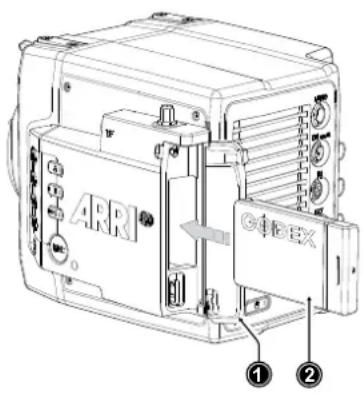
- To access the media slot, slide the media door release towards the camera back so that the spring loaded door (1) jumps open.
- With the contact pins first and the Codex label side facing out (away from the camera body), gently insert the drive (2) until it locks.
- Gently close the media door. Do not force the door closed if the drive is not fully inserted. Do not force the drive into the slot in wrong orientation - the contacts could be damaged.
Removing the Codex Compact Drive
Compact Drives do not have to be unmounted prior to removal, they can be removed whenever the drive LED shows solid green.
- Slide the media door release towards the camera back so that the spring loaded door jumps open.
- Grab the drive with your thumb and index finger and gently pull it out the media slot.
Erasing the Recording Medium
ADVICE
When erasing the recording medium, all data is completely erased and cannot be recovered afterwards. Make sure that all data has been copied from the medium before erasing.
Do not disconnect the camera from the power supply or turn it off while erasing.
Do not remove the recording medium while erasing.
Before using a Codex Compact Drive with the camera, it must be erased in the camera to create the required file system. Codex Capture drives are initialized with the UDF file system, which is read only for computers, and it is named ARRI_UDF until the first clip is recorded. Once a clip has been recorded, the name changes to the camera index letter and current reel number.
▶ Select MENU > Media > Erase Media.
▶ Press ERASE to start erasing the drive, or press CANCEL to cancel.
or
▶ Select Side Display > Settings > Erase Media.
▶ Press YES to start erasing the medium, press NO to cancel.
Compact Drive LED States
| LED State Media | State |
| Solid Green Drive | is in standby, ready to record and safe to remove. |
| Solid Red Read/write access during Playback or Recording. Do not remove the drive.Info: As recording is stopped, it takes a few seconds to finalize the recorded clip. During this time, the drive should not be removed. | |
| Blue flashing Drive | is being loaded or unloaded. |
| Red flashing Drive | error, see MENU >Alerts for details. |
| Off Drive cannot be accessed. Please try reinserting the drive. If the problem persists, check the drive state with Codex Device Manager. | |
Media Info
▶ Select MENU > Info > Media Info for additional information on the inserted medium.
16.1.1 Erase of Recording Media
Before using a Codex Compact Drive with ALEXA Mini LF, you need to erase it in-camera to create the required file system. Capture Drives are initialized with the UDF file system which is read-only for computers. Drives can be erased in the camera menu or by using camera button 2 in combination with the Function Button FN.
- Select MENU > Media > Erase Media.
A confirmation screen is displayed.
- Press ERASE to start erasing the drive, or press CANCEL to abort.
ADVICE
Erase Media completely removes all data and data can't be recovered. Make sure to copy all data from the drive before erasing.
Do not remove power or switch off the camera while Erase Media is in progress.
Do not remove the recording media from the recording module while Erase Media is in progress.
16.1.2 Remaining Recording Capacity and Media Information
The remaining recording time of the inserted drive at current FPS and codec combination, in real time is displayed on the HOME screen as well as in the status info of EVF/Monitor and the SDI outputs. When drive capacity is less than 2 minutes, capacity values start flashing.
Additional drive information can be found in the Media Info screen.
▶ Select MENU > Info > Media Info.
ADVICE
A maximum of 400 clips can be recorded on a drive. When the maximum of 400 clips is reached, the recording media will be declared as full and further recording onto the media is not possible.
16.2 Starting Recording via REC button
The REC button is located on the left side of the camera, the MVF-2 features another REC button. The camera status LED next to the REC button reflects the camera's status. Recording can only be started with a valid Compact Drive inserted. Starting recording returns the MVF-2 user interface to the home screen and disables the menu access as well as the HOME screen buttons FPS, SHUTTER and TC.
Other Ways to Start Recording
The camera offers various other ways to start recording:
• Through the LBUS connector, using ARRI Master Grips or the Operator Control Unit OCU-1
• Through the built-in white radio, using Wireless Compact Unit WCU-4 or Single Axis Unit SXU-1
- Through WiFi/LAN, using the web remote or applications communicating via CAP (Camera Access Protocol)
• Through the EXT connector, using the General Purpose I/O Box or a Remote Switch RS-4
• Through the RS connector, using Remote Switch RS-4
• A user button assigned with Record Start/Stop
16.3 Recording Codec
The selection of the recording codec is a crucial decision which needs to be discussed with the production company and post production. While lower bit rate formats offer longer recording times, they might introduce compression artifacts that can limit creative choices. Always test the full workflow pipeline with the preferred recording codec before shooting.
MXF (Material eXchange Format)
Both ARRIRAW and Apple ProRes files are recorded in an MXF (Material eXchange Format) container. An MXF container file can "wrap" different types of video and audio material along with associated metadata. The internal structure of these files is defined by the Operational Patterns (OP). Our cameras create MXF files with OP1a structure, which packages picture, sound and metadata into a single file. This structure is ideal for both camera acquisition and archiving, since audio and video is always kept together and virtually no data gets lost if recording is unexpectedly interrupted. OP1a also is a streaming format, which means that even incomplete files can be repaired and accessed up to the last recorded frame.
MXF/ARRIRAW
ARRIRAW data delivers unencrypted, uncompressed and uncompromised image quality. It offers the highest achievable resolution, the camera's natural color response and great exposure latitude as uncompressed and unprocessed sensor data. ARRIRAW images have only one channel. A color reconstruction algorithm calculates the missing components of each pixel based on the type and position of the array of colored filters (Bayer pattern) on the camera sensor.
ARRIRAW de-bayering is available through the ARRIRAW SDK or custom processing, which is implemented in most of the major post production tools for dailies processing and mastering.
ARRIRAW is used for cinema production, visual effects and high quality TV. It is the best format for creative color correction and visual effects work.
The camera will automatically calculate a CRC32C checksum for the image data inside each ARRIRAW frame. This checksum is recorded as part of the image header and can be used by software like ARRI Meta Extract, to verify that the ARRIRAW image content has not changed during any copy step. Note that this checksum does not validate the entire file, only the image data itself.
MXF/Apple ProRes
Recording in Apple ProRes is a cost efficient alternative to shooting ARRIRAW, as it requires less storage space and no further processing in post. The camera supports following Apple ProRes flavors:
MXF/Apple ProRes 422 HQ Use for high quality TV production. Suitable for creative color correction.
MXF/Apple ProRes 4444 Use for high quality TV and cinema production. Very suitable for creative color correction and visual effects work such as pulling mattes.
MXF/Apple ProRes 4444 XQ The ideal choice for productions that are shooting for premium image quality, are looking for extreme color grading and want to preserve the superior tonal range of ARRI's Log C signal.
Playback for MXF wrapped Apple ProRes clips has been added to macOS by Apple via their Pro Video Formats 2.1 back in January 2019. MacOS 10.14.3 or later is mandatory for this installer package.
ADVICE
Apple ProRes is a variable bitrate (VBR) codec. Depending on the content of your images the remaining recording time on the recording media can be longer than indicated by the camera.
File Structure
After a Codex Compact Drive was formatted in the camera, it is named ARRI_UDF until the first clip is recorded. Once a clip has been recorded, the name changes to the camera index letter and current reel number, which can be preset in the PROJECT menu. Clips are stored in a folder with the same name as the media.
The ALE file is an Avid Log Exchange file for Media Composer. It contains all static clip metadata, which is also embedded in each recorded clip.
Selection in Camera Menu
- Select Menu > Recording > Recording Codec
You have the following options:
| Recording Codec Color Coding Bit Rate (VBR, 24fps, | 3840x2160) |
| MXF/Apple ProRes 422 HQ 10bit YCbCr 705 Mbps | |
| MXF/Apple ProRes 4444 12bit YCbCr 1058 Mbps | |
| MXF/Apple ProRes 4444 XQ 12bit YCbCr 1608 Mbps | |
| MXF/ARRIRAW 12bit log 2389 Mbps |
- Select the desired recording codec.
Note: When the recording codec family is changed, the camera has to perform a partial software reload. A popup window shows the settings that are affected by the reload and that may not be available after the change. After confirming the popup window, the software is reloaded.
16.4 Recording Resolution
Recording Resolution Naming Scheme
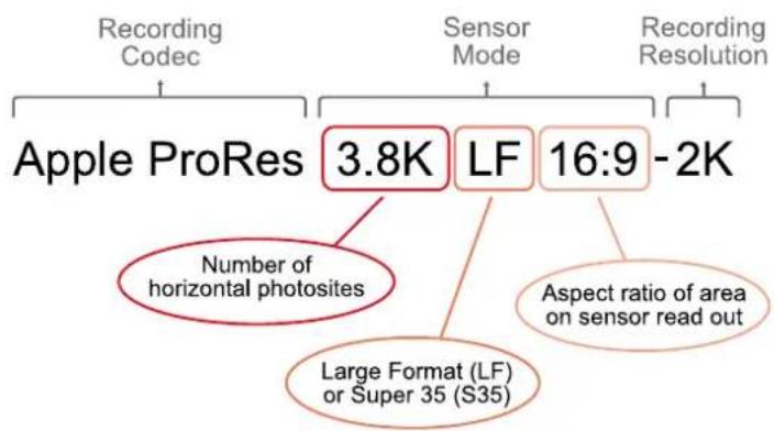
flowchart
graph TD
    A["Recording Codec"] --> B["Apple ProRes"]
    C["Sensor Mode"] --> D["3.8K"]
    E["Recording Resolution"] --> F["LF"]
    E --> G["16:9 -2K"]
    B --> H["Number of horizontal photosites"]
    F --> I["Large Format (LF) or Šuper 35 (S35)"]
    G --> J["Aspect ratio of area on sensor read out"]
Recording Codec
The Recording Codec defines the image content encoding. The options are ARRIRAW or Apple ProRes.
Sensor Mode
The sensor mode defines the size of the area on the sensor that is read out. This influences the maximum possible frame rate, the maximum data rate and what lenses can be used, as some lenses may not cover a large sensor area. The Sensor Mode part of the name is further divided into three parts:
- First is the number of horizontal photosites used on the sensor in "K" (thousands).
- Second is Large Format "LF" or Super 35 "S35", provided so a quick choice can be made without memorizing resolution numbers. "LF" in this context is any sensor mode with an area larger than the ALEXA Mini sensor in Open Gate, and "S35" is any sensor mode with an area equal to or smaller than the ALEXA Mini sensor in Open Gate.
• Third is the aspect ratio of the area on the sensor that is being read out.
Recording File Container Size
Recording File Container Size shows the resolution of the file that is being recorded in camera. Sometimes, as in ARRIRAW 3.4K S35 3:2 - 3.4K, the number of photosites read from the sensor and the number of pixels recorded are the same (here 3.4K), so no in-camera processing has been applied. In other cases, as for instance in Apple ProRes 3.8K LF 16:9 - 2K the number of photosites read out from the sensor is larger than the number of pixels recorded into the file. In this case, the in-camera processing has downsampled the 3.4K image from the sensor to a 2K image recorded to reduce the data rate. The aspect ratio of the recorded file is the same as that of the sensor mode and is therefore not noted again.
Recording Resolutions ARRIRAW
| Recording Resolution Sensor Active | Sensor Active Image Area (photosites) | Recording Resolution (Clip) | Recording Frame Rates | |
| Image Area (dimensions) | ||||
| 4.5K LF 3:2 Open Gate - 4.5K | 36.70 x 25.54 mm1.445 x 1.006" | 4448 x 3096 | 4448 x 3096 0.75 - 40 fps | |
| 4.5K LF 2.39:1 - 4.5K | 36.70 x 15.31 mm1.445 x 0.603" | 4448 x 1856 | 4448 x 1856 0.75 - 60 fps | |
| 3.8K LF 16:9 - UHD | 31.68 x 17.82 mm1.247 x 0.702" | 3840 x 2160 | 3840 x 2160 0.75 - 60 fps | |
| 2.8K LF 1:1 - 2.8K | 23.76 x 23.76 mm0.935 x 0.935" | 2880 x 2880 | 2880 x 2880 0.75 - 60 fps | |
| 3.4K S35 3:2 - 3.4K | 28.25 x 18.16 mm1.112 x 0.714" | 3424 x 2202 | 3424 x 2202 0.75 - 60 fps | |
Recording Resolutions Apple ProRes
| Recording Resolution Sensor Active | Sensor Active Image Area (photosites) | Recording Resolution (Clip) | Recording Frame Rates | |
| Image Area (dimensions) | ||||
| 4.5K LF 3:2 Open Gate - 4.5K | 36.70 x 25.54 mm1.445 x 1.006" | 4448 x 3096 | 4480 x 3096(Clip padding: 16px left and right) | 0.75 - 40 fps |
| 4.5K LF 2.39:1 - 4.5K | 36.70 x 15.31 mm1.445 x 0.603" | 4448 x 1856 | 4480 x 1856(Clip padding:16px left and right) | 0.75 - 60 fps |
| 4.3K LF 16:9 - UHD | 35.64 x 20.05 mm1.403 x 0.789" | 4320 x 2430 | 3840 x 2160 0.75 - 40 fps | |
| 4.3K LF 16:9 - HD | 35.64 x 20.05 mm1.403 x 0.789" | 4320 x 2430 | 1920 x 1080 0.75 - 75 fps | |
| 3.8K LF 16:9 - UHD | 31.68 x 17.82 mm1.247 x 0.702" | 3840 x 2160 | 3840 x 2160 0.75 - 60 fps | |
| 3.8K LF 16:9 - 2K | 31.68 x 17.82 mm1.247 x 0.702" | 3840 x 2160 | 2048 x 1152 0.75 - 90 fps | |
| 3.8K LF 16:9 - HD | 31.68 x 17.82 mm1.247 x 0.702" | 3840 x 2160 | 1920 x 1080 0.75 - 90 fps | |
| 2.8K LF 1:1 - 2.8K | 23.76 x 23.76 mm0.935 x 0.935" | 2880 x 2880 | 3072 x 3024(Clip padding: 96 px left and right, 72 px top and bottom) | 0.75 - 60 fps |
| 3.2K S35 16:9 - 3.2K | 26.40 x 14.85 mm1.039 x 0.585" | 3200 x 1800 | 3200 x 1800 0.75 - 75 fps | |
2.8K S35 4:3 - 2.8K
23.76 x 17.81 mm 0.935 x 0.701"
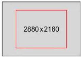
2880 x 2160 0.75 - 75 fps
2.8K S35 16:9 - HD
23.76 x 13.36 mm 0.935 x 0.526"
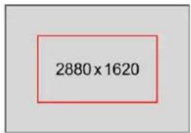
1920 x 1080 0.75 - 100 fps
- Select Menu > Recording > Recording Resolution.
- Select the desired recording resolution.
Note: The available recording resolutions displayed in the list depend on the currently selected Recording Codec.
Note: Changing between recording resolutions may require a software reload. Confirm the reload before it is performed. A popup window shows the settings that are affected by the reload and which may not be available in the new mode. After confirming the popup, the software is reloaded.
16.5 Audio Recording
The camera can record 4 channel linear PCM (24 bit, 48 kHz) audio. With audio recording enabled, all four audio channels are embedded in the SDI stream and output on the headphones out of the MVF-2.
Audio Inputs
The AUDIO connector (1) is located at the back of the camera. It is a 2-channel +24dBu line level audio input with additional 12V power output to supply microphone preamplifiers.
Signals connected to the AUDIO connector are recorded to audio channels 1 and 2.
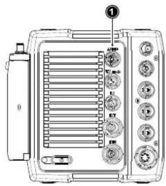
The dual gain built-in microphones (2=right mic, 3=left mic) are located at the camera front and can be used to record a scratch audio track. The audio signal from these microphones is recorded to audio channels 3 (left mic) and 4 (right mic) of the recorded clips. Per factory default, the built-in microphones are disabled.
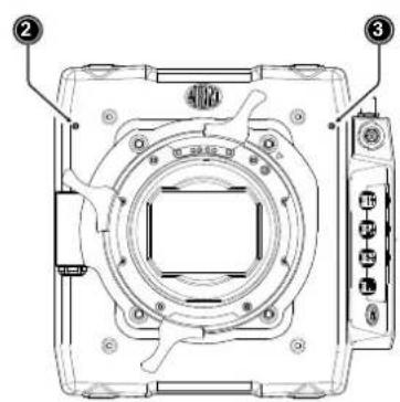
Audio Recording
▶ Select MENU > Recording > Audio Recording > Audio Recording to enable/disable audio recording. Enabled audio recording is indicated through the audio icon displayed on home screen as well as status info of the viewfinder and the SDI outputs:

Audio recording is enabled

Audio recording temporarily disabled, e.g. when the sensor frame rate does not match the project frame rate.
If audio recording is switched off, no audio is recorded internally, the SDI streams contains no audio and the headphones out on the MVF-2 is muted.
Channel 1/2 Control
- Select MENU > Recording > Audio Recording > Channel 1.
Select MENU > Recording > Audio Recording > Channel 2.
Following options are available:
Manual Manual allows the user to manually apply gain to the input signal on the channel to reach a correct level.
Manual (+L) A limiter prevents the signal from clipping if the input signal level combined with the set gain results in signal levels exceeding -6 dBFS.
Auto Auto matches a 4 dBu input signal to -20 dBFS. This setting leaves enough headroom for recording and avoids audio clipping. When Auto is selected, audio levels cannot be adjusted by the user.
- Set channel 1 and 2 control to your preference.
Channel 1/2 Gain
- Select MENU > Recording > Audio Recording > Ch 1 Gain
Select MENU > Recording > Audio Recording > Ch 2 Gain
- Using the CLICKWHEEL, adjust the channel gain. The meters show the current level of the channel signal in dBFS. Additionally audio levels are displayed on the HOME screen as well as the status info of the viewfinder and the SDI outputs.
Note: Gain setting is only available when audio recording is enabled and channel control is set to either Manual or Manual (+L).
Internal Microphones
The internal microphones can be used to record a reference track, sometimes also referred to as "scratch track". Some software tools can synchronize the master audio to the image using the reference track. The signal of the internal microphones is recorded to audio channels 3 and 4. The audio recording level of the internal microphones is fixed, with the left microphone (channel 3) using a +18dB higher gain than the right microphone in order to cover a wide range of audio levels.
▶ Select MENU > Recording > Audio Recording > Internal Microphones
to activate/deactivate recording of the internal microphones.

The microphone icon in the status info of EVF and the SDI outputs indicates active internal microphones.
Headphones Volume
-
Select MENU > Recording > Audio Recording > Headphone Volume.
-
Adjust the headphones' volume to your preference.
Test Tone
The camera can output a 1 kHz sine test tone on all recording channels, on headphones out and the SDI outputs.
▶ Select MENU > Recording > Audio Recording > Test Tone.
Following options are available:
- Off
-9 dBFS
-18 dBFS
-20 dBFS
Note: Test tone can only be activated when audio recording is enabled.
16.6 Rec Beeper and Tally Settings
- Select MENU > Recording > Rec Beeper/Tally.
Following options are available:
Rec Start Beeper The camera gives an acoustic indication for start of recording.
Rec Stop Beeper The camera gives an acoustic indication for stop of recording.
Media Full Beeper The camera gives an acoustic indication for stopping recording due to full card. For better distinction, a different sound pattern than the start/stop beeper is used.
Tally MVF-2 Enables the tally light on the MVF-2.
16.7 File Naming Scheme
The ALEXA Mini LF automatically names files as they are created on the recording media. While it is possible to change the file names later on a computer, it is not recommended, as the ALEXA naming scheme has been developed to minimize the risk of duplicate file names.
A typical clip name would look like this: A004C010_210421_RN9O.mxf
The clip name consists of eight parts:
Camera Index (A) One character, A-Z. User assignable, should match the camera unit.
For example, the camera index A can be assigned to the A camera, and B to the B camera etc.
Reel Counter (004) 3 characters, 001-999. Automatically assigned to each recording media, automatically advanced by one for each new media. The user can change the counter for the next reel. This should only be done under special circumstances, such as after changing the camera body in the middle of a shoot.
Clip Index (C) One character, fixed to C. Main use is to separate the reel counter from the clip counter.
Clip Counter (010) 3 characters, 001-999. Automatically advances each time a clip is recorded.
Date (210421) Current date, in order YYMMDD, as set in MENU > System > System
Time + Date, separated from the other naming components by under-scores.
Camera ID Prefix (R)
One character, A-Z. Typical use would be setting one camera's ID prefix to L (for left) and the other's to R (for right) for 3D applications.
Camera ID (N9O) The camera serial number encoded in 3 letters Base36 (0-9, A-Z).
N9O translates into decimal serial number 30156.
File name Extension (.mxf) All files are written as .mxf files.
The reel counter should be set to 001 at the beginning of a shoot. The camera will then automatically advance the reel number each time a new recording medium is loaded into the camera, formatted and recorded on. If a previously recorded medium is reloaded in the camera (comparable to a short end of a film roll), it will keep its reel number and the camera will continue the reel count. If the medium is loaded in another camera, it keeps its name, but a new folder with the according camera ID and reel number is created in the root folder of the medium. It is possible, but usually not necessary, to manually change the next reel number in the project menu.
16.8 Data Handling
Transferring recorded material from the original media should never be done using a simple file copy. There are different software solutions available that will copy a file to one or several destinations and perform a checksum calculation, comparing the material on the original media to the copies, to provide a minimum effort safety check of data integrity. We strongly recommend using copy software and tools with checksum calculation and verification. Checksum files should be calculated and generated as sidecard files at the first copy process.
There are many types of checksums, all with the same purpose: safe and fast copy at the same time.
For example, the 'MHL (Media Hash List)'. It's an XML based file with a fixed structure, which always contains the following information:
- Creator Info
- Name
- Username
- Hostname
- Tool
- Start date
- Finishing date
- hash
- Path to file
- File size in bytes
• Last modification of the file - xxhash (calculated)
- hash date
The ‘creator info’ is placed at the beginning of every ‘MHL’ checksum file. The rest of the ‘MHL’ file contains every single file incl. the xxhash value, which was calculated at the copy & checksum generation process.
Changing a file or some values inside the 'MHL' checksum file results in an error during the checksum verify process. Checksums should always be generated during the offload of the original camera negative and should remain next to the files until the final backup process. We strongly recommend a copy and checksum workflow from beginning (e.g. On-Set) to end (e.g. final LTO backup).
17 Playback
The camera offers various ways to start in-camera playback from the recording medium:
▶ Using the PLAY button on MVF-2
▶ Using user button 3 in combination with the Function Button FN
▶ Using a user button assigned with playback
▶ Using the Wireless Control Unit WCU-4
▶ Using the Web Remote
▶ Using apps communicating with the camera through the Camera Access Protocol (CAP)
Starting Playback Using the PLAY Button on MVF-2
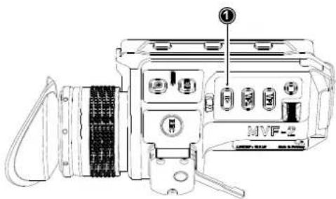
- Press and hold the PLAY button (1) for one second to start playback.
The camera goes into playback mode with the last recorded clip paused at start. - You may toggle between play and pause by briefly pressing the PLAY button again.
- To exit playback press the PLAY button for one second.
Playback Screen & Controls
When starting playback, the camera loads the last recorded clip (paused on the first frame). The playback screen offers the following controls:
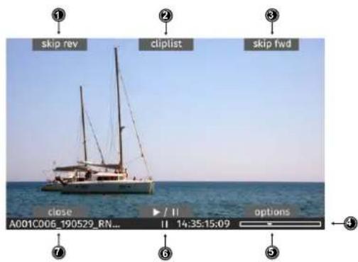
1 skip rev
Loads the previous clip from the cliplist.
2 cliplist
Select another clip for playback from a list of all clips on the recording medium.
3 skp fwd
Loads the next clip from the cliplist.
4 status bar
Shows clip name, timecode and playback progress bar of the selected clip.
5 options
Allows setting the clip end action.
6 play/pause
Toggles between play and pause. Play/pause can also be toggled by pressing the PLAY button on the MVF-2 or by pressing the JOGWHEEL. The JOGWHEEL can also be used to shuttle through a clip. While playback is paused, use the JOGWHEEL to shuttle through the clip frame by frame. While playing back, use the JOGWHEEL to increase or decrease the playback speed up to 512x forwards or backwards.
7 close Exits playback.
Cliplist
The cliplist lists all clips on the recording medium. For the selected clip, details like resolution, codec, duration and timecode are displayed. When browsing through the cliplist, the first frame of the selected clip is shown on EVF/Monitor and the SDI outputs for preview.
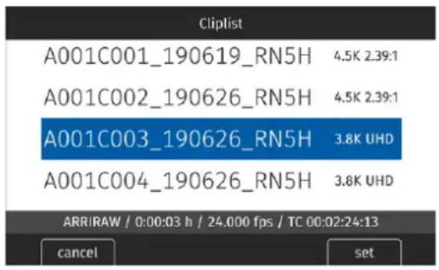
- Select PLAY > Cliplist.
- Select a clip.
For the selected clip, properties are displayed below the cliplist:
Codec: Recording codec of clip.
Duration: Clip duration at playback speed.
Project rate: Playback frame rate of clip.
Timecode: Start timecode of the clip.
- Press SET or the JOGWHEEL to load the clip for playback.
- Press CANCEL to leave the cliplist and return to the play screen.
Note: Clips may be grayed out if they can not be played back because their recording resolution is not compatible with the currently set recording resolution.
Playback Options
- Select PLAY > Options.
The Play End Mode defines the behavior when playback reaches the end of a clip and offers the following options:
| Pause on end | Playback pauses at the end of the clip. |
| Pause on start | Playback pauses at the beginning of the clip. |
| Loop | Playback continues from the beginning of the same clip again. |
| Play next clip | Playback continues with the next clip in the cliplist. |
| Exit playback | Camera exits playback. |
- Set the desired play end mode.
18 Monitoring
18.1 Status Information and Status Overlays
EVF and SDI Status Information
The camera displays camera status information on the MVF-2 and the SDI outputs. At the top and bottom of the screen, the camera displays textual status information. The top status bar consists of sensor FPS, shutter angle, exposure index, ND filter and white balance. The bottom status bar displays information about the battery level, reel and clip, camera status, remaining recording time and timecode.
On the left and right of the screen, icons provide information about the current status of the camera. The icons are organized into groups. The left icon groups display the EVF/SDI configuration as well as the camera configuration. Additionally various other icons are displayed below to indicate certain active parameters. The right side shows the audio meters as well as other icons (described below). Furthermore the user can activate the display of additional camera information such as lens data and electronic horizon.
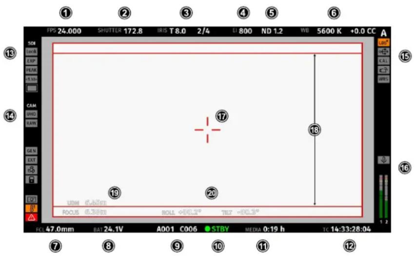
Top Section
1 FPS Shows the current sensor frame rate. The FPS label turns orange if the sensor frame rate does not match the project rate.
2 SHUTTER Shows the current shutter value (here: shutter angle).
3 IRIS Shows the current lens iris, including sub stops.
When using a lens extender, the iris value is displayed in brackets (recalculated value).
4 EI Shows the current exposure index.
5 ND Shows the current setting for the ND filter.
6 WB Shows the current white balance value.
Bottom Section
7 FCL Shows the current focal length of the lens (if lens data is available).
When using a lens extender, the focal length value is displayed in brackets (recalculated value).
8 BAT Shows the current battery supply level. If the level is below the configured warning level, the value is flashing orange.
9 CLIP Shows the current reel and clip number.
| 10 Camera Status | STBY | Standby - ready for recording. |
| REC | Recording. | |
| PLAY | Camera is in playback mode. | |
| ERASE | Medium erase in progress. Active erasing disables recording. | |
| None | Idle, recording not possible (e.g. no media inserted, media is full). | |
| ERROR | System error occurred. See MENU >Alerts for details. |
| 11 | MEDIA | Shows the remaining capacity of the recording medium at current FPS and codec combination in real time. When medium capacity is less than two minutes, capacity values starts flashing orange. |
| 12 | TC | Shows the current timecode. The TC label turns orange if the sensor frame rate does not match the project rate. |
Left Section
| 13 EVF / SDI Status | Look | Shows the current EVF/SDI processing (Look, Log C or ALEXA Classic 709). |
| EXP | Indicates that the exposure tool is active on the respective output. | |
| PEAK | Indicates that peaking is active on the respective output. | |
| AD | Indicates that anamorphic desqueeze is active and which lens squeeze factor is selected. | |
| MAG | When using Magnification, the magnification icons indicate that the output shows less image content than actually recorded. |
| 14 Camera Status | UHD | Shows the current recording resolution. |
| RAW | Shows the current recording processing (RAW or Log C). | |
| GEN | Indicates that Genlock is activated. If orange: Genlock signal is missing or not usable. | |
| EXT | Indicates that EXT sync mode is activated. | |
| FAN | Shows that the camera needs to increase the fan speed to cool the camera properly. | |
| LOCK | Indicates that the camera controls are locked. | |
| GRAB | Frame Grab is active. | |
| TEMP | Indicates that the camera temperature is outside of its optimal range. | |
| ALERT | Indicates an active alert state. |
Right Section
| 15 Camera Index Letter | Shows the camera index letter. |
| LDS | Shows that the LDS interface has been disabled manually. |
| USB | Shows a connected USB medium. |
| CAL | Lens motor calibration is in progress. If orange: lens motor calibration is required. |
| WiFi | WiFi is active. |
| WRS | White Radio is active. |
| 16 MIC | Internal microphones are active. |
| Audio Meters | Shows the current level of camera audio channel signals. If audio recording is currently not possible, an orange speaker icon with a small x is shown. Black markers at signal levels -20, -18, -9 dBFS for reference test tone. Yellow marker at -5 dBFS and red marker at -2 dBFS indicate a signal close to clipping. A red frame around the meter indicates a clipping at the A/D stage. |
Other
17 Center Cross Marks the center of the image to help in framing.
18 Frame Line Frame line (here: ARRI 1:1.85)
19 UDM Shows measurements from Ultra Distance Measures. Focus Shows the current focus distance of the lens (if lens data is available). When using a lens extender, the focus distance value is displayed in brackets (recalculated value).
20 HOR Shows the electronic horizon or numeric roll and tilt values.
Note: Export laws dictate that for sensors made up of more than a certain number of photo sites, we cannot record positional information like roll and tilt, lest the camera be classified as military equipment. This rule looks at the total number of photosites on the sensor and does not concern itself with individual recording formats that may record fewer photosites.
Configuration of Overlays
- Select MENU > Monitoring > EVF/Monitor > EVF Overlays.
Select MENU > Monitoring > EVF/Monitor > Monitor Overlays.
Select MENU > Monitoring > SDI > SDI Processing > SDI Overlays.
Following settings are available:
Frame Lines Sets frame lines on or off. Used as a framing reference tool with typically an image frame, a center mark and aspect ratio. For information on setting frame lines, see "Frame Lines", page 91.
Frame Line Shading Applies an outside shading to the area between the frame line and the remaining active image area.
Center Mark Sets the center mark between Off, Dot, Small Dot, Cross or Small Cross.
Surround Mask Select to adjust the surround mask settings. If surround view is set to On, it must be separated from the recorded image area to allow proper framing, either as black line, colored line, or semi transparent with 25, 50, 75 or 100% percent opacity (only a single semi transparent option is available for the MVF-2 flip-out monitor).
Status Info Only for EVF and SDI. Sets camera status overlays between Off, Overlay (status on the active image), or Safe (status outside the active image).
Configuration of Status Info Components
- Select MENU > Monitoring > EVF/Monitor > EVF Overlays > Status Components.
Select MENU > Monitoring > SDI > SDI Processing > Overlays > Status Components.
- Following settings are available:
Info 1 Enables/disables the top and bottom section of the status info.
Info 2 Enables/disables the left and right section of the status info.
Timecode Enables/disables display of the timecode on the bottom right of the image.
Audio Enables/disables display of the audio levels located on the lower right side of the image.
Lens Data Enables/disables iris and focal length readings.
Lens Focus Distance Sub-option of lens data setting. Enables/disables display of focus distance readings (19), located on the lower left corner of the image.
UDM Sub-option of lens focus distance setting. Enables/disables display
of distance readings from the Ultrasonic Distance Measure UDM-1 (in combination with LCUBE CUB-1). Located above the lens focus distance overlay.
Camera Index Letter Displays the camera index letter in the top right corner of the image.
Helps to identify camera image output when shooting with multiple cameras. Note: Only available for SDI.
Electronic Horizon Displays an horizon overlay representing the roll and tilt of the cam-
era measured by the camera's position sensor. This sensor can be reset, if it appears to have an offset. For information on resetting the camera's position sensor, see "Reset of Electronic Horizon", page 115.
Show Numeric Values Sub-option of electronic horizon. Shows the tilt and roll of the camera in degrees as measured by the camera's position sensor (20).
- Configure the status info components to your preference.
18.1.1 Flip-out Monitor Status Bar
The flip-out monitor of the MFV-2 shows slightly different overlays than the EVF and the SDI outputs. When set to display the camera live image, a status bar is displayed below the image. The monitor status bar offers the display of five groups:
- Main camera parameters: FPS, shutter, exposure index, ND filter and white balance (as shown below)
• Audio meters and timecode - Status icons
- Lens data: Focus distance, iris and focal length
• Recording: media remaining capacity, clip duration, codec and battery level
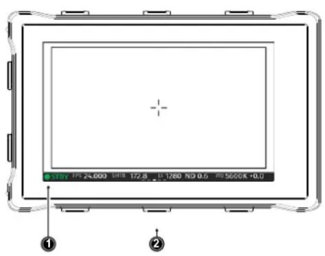
Use the lower screen buttons (2) to change the status bar (1) content. The lower center screen button returns to display the main camera parameters.
18.1.2 Overlay Menu
The overlay menu offers quick access to the main camera parameters.
When activated, it is visible in the top section of the image on the MVF monitor and EVF and on any SDI output which has SDI processing activated. The overlay menu is a quick way to change the following camera settings:
- Sensor FPS
• Shutter (Shutter Angle / Exposure Time) -
Exposure Index
-
ND filter
- White Balance
Sensor FPS, Shutter and White Balance cannot be changed manually, but in the range of their user predefined lists. ND filter is changed instantly and requires no additional confirmation step.
A white frame marks the selected parameter. A white block indicates active edit mode.
Activation and Control Using the Camera Buttons
- Activate the overlay menu by pressing FN + 1 .
- Select a parameter with buttons 1 or 2.
- Start editing the parameter by pressing button 3.
- Select the new parameter value with buttons 1 or 2.
- Confirm the new value by pressing button 3.
- If required, repeat steps 2-5 for other parameters.
- Exit the overlay menu by pressing FN + 1 .
Activation and Control Using a User Button
- Assign a user button to "Overlay Menu".
- Activate the overlay menu by pressing the user button.
- Select a parameter with the JOGWHEEL of the MVF-2.
- Start editing the parameter by pressing the JOGWHEEL.
- Change the value of the parameter with the JOGWHEEL.
- Confirm the new value by pressing the JOGWHEEL.
- If required, repeat steps 3-6 for other parameters.
- Exit the overlay menu by pressing the user button.
18.2 Surround View
Surround View displays additional pixels outside the recorded image area (1), allowing the operator to see outside the recorded image and keep unwanted objects, such as microphone booms, out of the shot. The surround view area (2) can be separated from the recorded image area by setting the surround mask (here: 50% opacity mask). To view only the recorded image, set surround view to off.
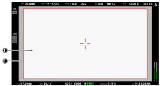
- Select MENU > Monitoring > EVF/Monitor > Surround View.
Select MENU > Monitoring > SDI > SDI processing > Surround View.
- Set Surround View on or off. Per factory default surround view is enabled.
Note: Surround View is not available for recording resolutions
4.5K LF 3:2 Open Gate - 4.5K
2.8K LF 1:1 - 2.8K
2.8K S35 4:3 - 2.8K
Surround Mask
The surround mask setting helps to visually separate the surround view from the recorded image area.
- Select MENU > Monitoring > EVF/Monitor > EVF Overlays > Surround Mask.
Select MENU > Monitoring > SDI > SDI Processing > SDI Overlays > Surround Mask.
Following options are available:
Black Line Surround mask is separated with a black line.
Colored Line Surround mask uses the same color as frame lines.
Mask 25% Surround mask is displayed with 25% opacity.
Mask 50% Surround mask is displayed with 50% opacity.
Mask 75% Surround mask is displayed with 75% opacity.
Mask 100% Surround mask is displayed with 100% opacity.
-
Set the preferred surround mask for EVF and/or SDI
-
Select MENU > Monitoring > EVF/Monitor > Monitor Overlays > Surround Mask.
Following Options are available:
Black Line Surround mask is separated with a black line.
Colored Line Surround mask uses the same color as frame lines.
Semitrans. Mask Surround mask is displayed with 50% opacity.
- Set the preferred surround mask for the MVF-2 Monitor.
Frame Border
The frame border setting helps to visually separate the recorded image area from the status overlays for those recording resolutions that do not support to display surround view (e.g. 4.5K LF 3:2 Open Gate - 4.5K).
-
Select MENU > Monitoring > EVF/Monitor > Frame Border.
Select MENU > Monitoring > SDI > SDI Processing > Frame Border. -
Set Frame Border on or off.
18.3 Magnification
When shooting with frame lines or aspect ratios that only use a cropped area of a recording resolution the actual image content defined by the frame line might not be displayed large enough.
The magnification setting gives the user access to variably scaling of the monitoring outputs and sets a persistent image magnification, so the area defined by the frame line can be displayed as large as desired.
Magnification can be adjusted in steps of 1% from 100% to 200% for the EVF and the SDI outputs, individually or globally.
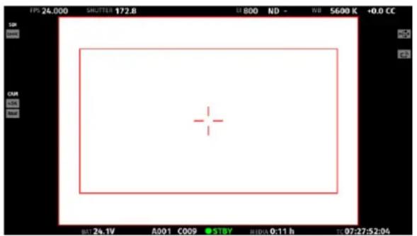
natural_image
Empty white rectangle with a red crosshair at center, displayed in a software interface (no text or symbols on the main area)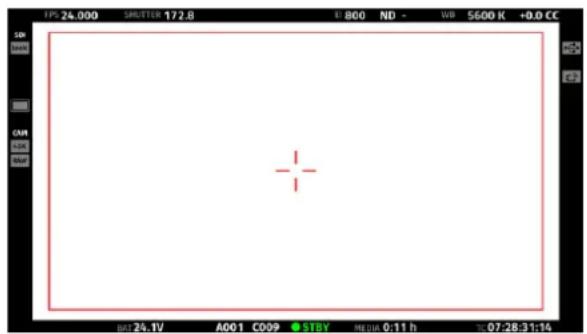
natural_image
Blank white canvas with a red crosshair in the center, no text or symbols visible.Two screen shots from an ALEXA Mini LF in recording resolution LF Open Gate 4.5K with a 1.78 UHD frame line (red rectangle) applied. The left screen shot shows the SDI output without magnification applied. The right screen shot shows the SDI output with magnification applied to enlarge the image (in this example set to 135%).
The magnification icon on the left side of the status info indicates that the recorded area exceeds the displayed image:

Indicates that the recorded image content horizontally (left and right) extends beyond what is visible on the output.

Indicates that the recorded image content vertically (above and below) extends beyond what is visible on the output.

Indicates that the recorded image content horizontally and vertically extends beyond what is visible on the output.
Setting the Magnification
The camera menu offers the following settings to adjust magnification:
▶ Select MENU > Monitoring > Master Magnification
to set the magnification level of the EVF and the SDI outputs simultaneously.
Note: When individual outputs have been set to different magnification values, the master magnification menu entry shows "-". Changing the master magnification will force the magnification of all outputs to the new value.
▶ Select MENU > Monitoring > EVF/Monitor > Magnification
to set the magnification level of the EVF and the flip-out monitor.
▶ Select MENU > Monitoring > SDI > SDI Processing > Magnification
to set the magnification level of the SDI outputs.
Note: Magnification can only be applied on the SDI output(s) with SDI image set to processed.
Note: Magnification is not available when using recording formats that record 2K or HD clips.
Note: Magnification is reset to 100% when the recording resolution is changed.
18.4 Frame Lines
To aid in framing, both the viewfinder and the SDI outputs (if set to processed) can display frame lines overlaid on the image. Frame lines can be considered electronic versions of ground glass markings in film cameras.
You can configure which frame line the camera should show and how it should be displayed (color and transparency). You can also configure up to two user rectangles which allow you to mark a rectangular area on the image, e.g. for marking an area that you need to keep clear during shooting for later VFX insertion.
Custom frame lines can be created using the Frame Line & Lens Illumination Tool.
A standard set of frame lines for different aspect ratios is provided in the camera, the availability depends on the selected recording resolution.
Setting the Frame Line
- Select MENU > Monitoring > Frame Lines > Frame Line.
A list of installed frame lines is displayed.
- Select a frame line from the list or import a custom frame line from an inserted USB medium.
Note: ALEXA Mini LF features a frame line "ARRI 2.00 Ana 2.0x N" for LF Open Gate 4.5K, marking the 2880x2880 area. This is for the use of 2x anamorphic lenses for a 4K UHD mandate when the intended deliberable has a 2:1 aspect ratio.
Frame Line Color
The frame line color is a global setting and defines the color of the frame line, the center mark, the user rectangle(s) and the surround mask (if mask is set to Colored Line).
- Select MENU > Monitoring > Frame Lines > Frame Line Color.
The following frame line colors are available:
| Red | Magenta |
| Green | Yellow |
| Blue | Black |
| Cyan | White |
- Set the desired frame line color.
User Rectangles
To further aid in framing, the camera offers to display two custom user rectangle overlays.
You can configure width, height and offset (position from left and top of image area) in per mill.
- Select MENU > Monitoring > Frame Lines > User Rectangles.
You have the following options:
| Off | User Rectangles are not displayed. |
| Rect 1 | Only user rectangle 1 is displayed. |
| Rect 2 | Only user rectangle 2 is displayed. |
| Rect 1 + 2 | User rectangles 1 + 2 are displayed. |
-
Configure the display of user rectangles.
-
Select MENU > Monitoring > Frame Lines > User Rectangle 1 or MENU > Monitoring > Frame Lines > User Rectangle 2.
You have the following options:
| Width | Adjusts the user rectangle width in the range of 0-999. |
| Height | Adjusts the user rectangle height in the range of 0-999. |
| Offset Left | Adjusts the horizontal user rectangle offset in the range of 0-1000. |
| Offset Top | Adjusts the vertical user rectangle offset in the range of 0-1000. |
| Reset All | Resets all values. |
- Configure the user rectangle according to your needs.
- To reset the configuration, press Reset all.
Frame Line Outside Shading
The Frame Line Outside Shading setting applies an outside shading to the area between the frame line and the remaining active image area.
- Select MENU > Monitoring > EVF/Monitor > EVF Overlays > Frame Line Shading.
Select MENU > Monitoring > SDI > SDI Processing > Overlays > Frame Line Shading.
Following options are available:
| Off | Frame line shading is not used. |
| 25% | The area outside the frame line is shaded with 25% opacity. |
| 50% | The area outside the frame line is shaded with 50% opacity. |
| 75% | The area outside the frame line is shaded with 75% opacity. |
| 100% | The area outside the frame line is shaded with 100% opacity. |
- Set the frame line outside shading for EVF and/or SDI.
- Select MENU > Monitoring > EVF/Monitor > Monitor Overlays > Frame Line Shading.
Following options are available:
| Off | Frame line shading is not used. |
| 50% | The area outside the frame line is shaded with 50% opacity. |
| 100% | The area outside the frame line is shaded with 100% opacity. |
- Set the frame line outside shading for the Monitor.
Frame Line Intensity
You can set the brightness of the frame line, center cross and user rectangles.
- Select MENU > Monitoring > Frame Lines > Frame Line Intensity
- Set the frame line intensity in a range from 1 to 4.
Frame Lines Saved in Metadata
The camera records frame lines from the active frame line file into metadata. This metadata is written to all recording formats and is present on all SDI outputs. The frame line metadata makes the original camera frame lines available during post production for editing, color grading or compositing tools and can be displayed as an overlay in the respective image viewer.
ADVICE
Frame lines created for a recording resolution other than the currently active are not selectable.
18.5 Anamorphic Desqueeze
Setting the Lens Squeeze Factor
The lens squeeze factor determines the factor that is used for anamorphic desqueeze on EVF/Monitor and SDI. This value is also written into the metadata of the clip and allows video players and editing software to automatically desqueeze clips that have been shot with anamorphic lenses.
▶ Select MENU > Recording > Project Settings > Lens Squeeze Factor and select the appropriate factor.
Anamorphic desqueeze is automatically activated on EVF/Monitor and the SDI outputs.
Activation of Anamorphic Desqueeze for EVF/Monitor and SDI
With the desqueeze factor defined in the project settings, anamorphic desqueeze can be then enabled and disabled for EVF/Monitor and SDI so that the image is displayed with the correct aspect ratio.
-
You have the following options:
-
Select MENU > Monitoring > EVF/Monitor > Anamorphic Desqueeze.
-
Select MENU > Monitoring > SDI > Anamorphic Desqueeze.
-
Enable or disable anamorphic desqueeze for the EVF/Monitor and/or SDI outputs.
-
Additionally you can assign "EVF/Mon. Desqueeze" and "SDI Desqueeze" to user buttons to quickly enable and disable anamorphic desqueeze for the corresponding path. For further information on how to assign functions to user buttons please see "User Buttons", page 121.
18.6 Exposure Tools
The camera offers two exposure tools for evaluation of the image exposure levels, False Color and Zebra. You can select which exposure tool you want to use to evaluate the image exposure. The exposure tool can be activated through
• the EXP button on the MVF-2 (for EVF and Monitor)
- a user button assigned with EVF/Mon. Exp. Tool (for EVF and Monitor)
- a user button assigned with SDI Exp. Tool (for the SDI Outputs)
• the EVF/Mon. and SDI exposure tool entries in the camera menu
Activation of Exposure Tool with MVF-2
▶ To activate the exposure tool on both EVF and Monitor, press the EXP button (1) on the MVF-2. Press the EXP button again to deactivate the exposure tool.
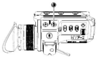
Activation of Exposure Tool with User Buttons
- Assign a user button with EVF/Mon. Exp. Tool
to be used for activation of the exposure tool on EVF and Monitor. -
Assign a user button with SDI Exp. Tool
to be used for activation of the exposure tool on the SDI outputs. -
Press the user button to toggle the exposure tool on/off.
For more information on user buttons please see "User Buttons", page 121.
Activation of Exposure Tool in Camera Menu
-
Select MENU > Monitoring > EVF / Mon. > Exposure Tool
to activate the exposure tool on EVF and Monitor. -
Select MENU > Monitoring > SDI > SDI Processing > Exposure Tool
to activate the exposure tool on the SDI outputs.
18.6.1 False Color
The false color display is a tool to check for correct exposure. It can be activated on EVF/Monitor and/or the SDI outputs, and takes the respective gamma setting as a basis for calculation. When active, the image is turned into a gray scale image with important luminance ranges shown in signal colors. Note that the false color tool is only suitable for checking exposure and is not an appropriate tool for checking other image parameters or sensor quality. Activating false color replaces luminances with the following colors:
| Exposure | Signal Level | Color | |
| White Clipping | 100% - 99% | Red | |
| Just below white clipping | 99% - 97% | Yellow | |
| One stop over medium gray (Caucasian skin) | 56% - 52% | Pink | |
| 18% medium gray | 42% - 38% | Green | |
| Just above black clipping | 4.0% - 2.5% | Blue | |
| Black clipping | 2.5% - 0.0% | Purple | |
False Color Configuration
▶ Select MENU > Monitoring > Exposure Tools > Select EVF/Mon. Exp. Tool and select False Color to use False Color as exposure tool for EVF and Monitor.
▶ Select MENU > Monitoring > Exposure Tools > Select SDI Exp. Tool and select False Color to use False Color as exposure tool for the SDI outputs.
False Color Mode
The result of activating false color can be varied to either Monitoring-based or Log C-based. This choice is global and will be valid for all viewing outputs.
Monitoring-based
When choosing Monitoring-based false color and false color is activated (with the EXP button on the viewfinder, for example), false color is calculated based on the video signal of the respective monitoring output. In other words, whatever is seen on the image path is the basis for calculating false color.
If you have a monitor output or the viewfinder configured to show Log C, false color levels will be calculated based on the Log C signal.
If you have a monitor output or the viewfinder configured to LOOK or ALEXA Classic 709, false color levels will be calculated based on the image with the look applied or the ALEXA Classic 709 image respectively.
Log C-based
When choosing Log C-based false color, false color is always calculated based on the Log C image. When false color is activated (with the EXP button on the viewfinder, for example), the respective monitoring output is switched to Log C processing, false color levels are calculated based on the Log C signal and false color is activated. When de-activating false color, the image path is switched back to its previous processing and false color is switched off. This setting makes most sense for projects that record Log C images. While your monitoring image paths can be set to show Rec 709 or a look to provide a preview for all, you will want to know the exposure levels of the signal you are actually recording (Log C) when checking false color. Log C-based false color mode is mandatory when using HDR ALF-2 files.
ADVICE
When a HDR ALF-2 look file is loaded and activated in the camera, false color mode automatically switches to 'Log C-based'. This is because HDR look files do not generate video signals over 75%, which means that overexposure might not be indicated correctly in 'Monitoring-based false color' mode.
When you are using a look file that does not utilize the full signal level range and you activate false color on a monitoring path where Look processing is active, false color will not indicate over- or underexposure. This specifically applies to Rec 2100 PQ Look files, as they level out at a maximum signal level of 75%.
When using look files with extreme color grading, it is possible for 'Monitoring-based' false color to show an inaccurate result.
18.6.2 Zebra
In Zebra mode, the camera overlays up to two luminance ranges with diagonal stripes. High zebra ranges above, Mid zebra around the user defined luminance value.
Zebra Configuration
▶ Select MENU > Monitoring > Exposure Tools > Select EVF/Mon. Exp. Tool and select Zebra to use Zebra as exposure tool for EVF and Monitor.
▶ Select MENU > Monitoring > Exposure Tools > Select SDI Exp. Tool and select Zebra to use Zebra as exposure tool for the SDI outputs.
Zebra Setup
- Select MENU > Monitoring > Exposure Tools > Zebra Setup.
Following settings are available:
| Zebra Mode | Sets the zebra mode to High, Mid, or both. |
| High Zebra Level | Sets the exposure level (in %) above which high zebra is active. |
| High Zebra Color | Sets high zebra pattern color. |
| Mid Zebra Range | Sets the active range (in %) around a mid zebra level. |
| Mid Zebra Color | Sets the mid zebra pattern color. |
- Adjust the Zebra settings to your preference.
Note: Zebra is not available on image paths with processing set to Log C. Please use False Color to check the image exposure on image paths with processing set to Log C.
18.7 Focus Tools
18.7.1 Peaking
Peaking highlights in-focus image areas for better focus judgment. Peaking can be activated through the camera menu or a user button.
Peaking Configuration
- Select MENU > Monitoring > EVF/Monitor > EVF/Monitor Processing > Peaking to configure Peaking for EVF and Monitor.
- Select MENU > Monitoring > SDI > SDI Processing > Peaking to configure Peaking for the SDI outputs.
- The following options are available:
Peaking Activates Peaking for the corresponding output.
Peaking Mode
Select between Color and Aperture. Select color peaking to overlay in-focus areas with a color, and select aperture peaking to enhance object edges only.
Peaking Level Sets a peaking strength in range from 1 (minimum) to 20 (maximum).
Peaking Offset Shift
Adjusts the threshold for Color Peaking to become active, relative to the peaking level. Note: A negative offset shift, in particular with high ASA ratings, can increase the peaking results.
Color Select the color for Color Peaking.
Activation of Peaking
-
Assign a user button with EVF/Mon. Peaking to be used for activation of Peaking on EVF and Monitor.
-
Assign a user button with SDI Peaking to be used for activation of Peaking on the SDI outputs. Additionally SDI Peaking can be activated through MENU > Monitoring > SDI > SDI Processing > Peaking.
-
Press the user button to toggle Peaking on/off
- Select MENU > Monitoring > SDI > SDI Processing > Peaking
For more information on user buttons please see "User Buttons", page 121.
18.7.2 Zoom
The camera supports to zoom into the image e.g. to better judge focus. The camera offers six zoom positions: center, top left, top center, top right, bottom right, bottom left. While Zoom is activated, the zoom position can be changed by using the JOGWHEEL or the soft buttons on the MVF-2, if the monitor is flipped out and set to display the live image. Active Zoom is indicated by an orange frame around the image. Frame lines are deactivated while Zoom is active.
Note: Anamorphic Desqueeze is temporarily disabled while Zoom is active.
Zoom on EVF/Monitor
The MVF-2 has a dedicated ZOOM button (1).
- Press the ZOOM button to activate/deactivate Zoom on EVF and Monitor.
- To change the Zoom position, rotate either the JOGWHEEL or the USER WHEEL.
Note: Changing the zoom position using the JOG-WHEEL or USER WHEEL is not supported when the monitor is set to display the HOME screen or the camera menu.
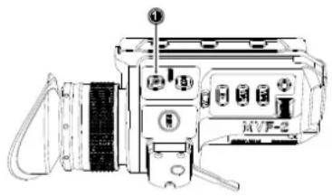
Zoom on SDI
Zoom on the SDI outputs can only be activated through a user button. The camera offers three SDI Zoom related user button functions:
- Assign a user button with SDI Zoom.
The SDI Zoom user button activates/deactivates Zoom on the SDI outputs.
- Assign a user button with SDI Zoom Position.
The SDI Zoom Position user button changes the Zoom position while SDI Zoom is activated.
- Assign a user button with SDI Zoom (Smart).
The SDI Zoom (Smart) user button activates Zoom on the first button press, further button presses change the zoom position and a button long press deactivates Zoom.
18.8 SDI Outputs
SDI Format
The SDI BNC connectors output SDI signals in 1920 x 1080 (422 1.5G, 422 3G, 444 3G) and 3840 x 2160 (422 6G) according to SMPTE standards 292M, ST 424:2012 and ST 2081. Signals are output in legal range.
- Select MENU > Monitoring > SDI > SDI 1 Format or
- Select MENU > Monitoring > SDI > SDI 2 Format.
The following SDI formats are available:
| Format Resolution Sampling Fps | |||
| 422 1.5G HD 1920 x 1080 4:2:2 YCbCr 23.976 p/psf | 24 p/psf25 p/psf29.97 p/psf30 p/psf | ||
| 422 3G HD 1920 x 1080 4:2:2 YCbCr 48 p** | 50 p59.94 p60 p | ||
| 444 3G HD 1920 x 1080 4:4:4 RGB 23.976 p | 24 p25 p29.97 p30 p | ||
| 422 6G UHD*(SDI 2 ONLY) | 3840 x 2160 4:2:2 YCbCr 23.976 p | 24 p25 p29.97 p30 p | |
3. Set the desired SDI format.
* not available for LF 16:9 HD and LF 16:9 2K mode
**48p may not be supported by some SDI devices, as this is not a defined frame rate according to the SMPTE standard.
Note: Clean (non-processed) 422 6G UHD monitoring is only available on the SDI 2 output.
SDI Processing
You can configure the SDI processing elements.
▶ Select MENU > Monitoring > SDI > SDI Processing.
Following options are available:
| Surround View | Activates or deactivates surround view. |
| Magnification | Apply magnification to the SDI outputs. |
| Exposure Tool | Activates or deactivates the exposure tool. |
| Peaking | Configures peaking for SDI. |
| Overlays | Configures the SDI overlays. |
SDI Frame Rate
You can set the frame rate together with the scan format on the SDI output. If the frame rate is lower than the sensor fps, frame drops will occur. If it is higher, duplicate frames will be output. The available frame rates depend on the selected SDI format.
▶ Select MENU > Monitoring > SDI > SDI 1 Frame Rate or
▶ Select MENU > Monitoring > SDI > SDI 2 Frame Rate
and select the desired frame rate.
Available scan formats are:
p (progressive) Transmits images line by line starting at the top left pixel.
psf (progressive segmented frame) Splits progressive images into fields (odd lines
and even lines). Transmits these (all odd before all even) line by line.
SDI 3G Level
For the single link 3G SDI formats, you can choose whether to use 3G level A or B. Refer to the manual of your connected devices to decide which 3G level to choose.
▶ Select MENU > Monitoring > SDI > SDI 1 3G Level or
▶ Select MENU > Monitoring > SDI > SDI 2 3G Level and select the desired 3G level.
SDI Image
The SDI image setting determines how images are output over SDI:
▶ Select MENU > Monitoring > SDI > SDI 1 Image or
▶ Select MENU > Monitoring > SDI > SDI 2 Image.
Following options are available:
Clean Images are identical to the images that the camera records internally. They do not contain any overlays and do not show any surround view.
Processed Images may contain overlays and show surround view.
SDI 1 and 2 cannot be configured completely independently from each other in reference to the image setting. The SDI 1 setting determines the available options for SDI 2. The following combinations are possible:
| SDI 1 SDI 2 | |
| processed clean | |
| processed processed | |
| clean clean |
If both SDI 1 and 2 are supposed to show processed images, SDI 2 needs to be configured as SDI 1 clone.
SDI 2 Clone
You can set SDI 2 as a clone of SDI 1. SDI 2 will inherit all settings from SDI 1. The configuration options for SDI 2 are grayed out while it is configured as a clone of SDI 1. If you change a value for SDI 1, the same value becomes active for SDI 2 as well.
▶ Select MENU > Monitoring > SDI > SDI 2: Clone SDI 1.
18.8.1 Preventing Damage to SDI Outputs
Under certain conditions the SDI outputs of cameras can be damaged through a power surge. This can be avoided by connecting power and BNC cables in a particular order and by using shielded power cables and high quality undamaged BNC cables.
Problem Description
Camera SDI outputs can get damaged when an accessory is connected to the SDI output and is powered through an unshielded cable. All cameras, including all ARRI cameras and other SDI devices, can be affected by this.
This is especially critical for cameras with SDI connections capable of SDI 6G or higher (even if set to work at lower bit rates like SDI 1.5G). Cameras with SDI connections capable of SDI 1.5G or SDI 3G can be protected more efficiently without decreasing the SDI signal quality.
This damage to the SDI connection can occur when connecting an unshielded power cable to an accessory that is already connected to the SDI output of the camera. If the plus pin is contacted before the negative pin, the BNC cable will close the current circuit resulting in a fatal damage of the included SDI driver chip which itself is not designed to handle such high currents.
This problem can also occur when disconnecting an unshielded power cable of an accessory that is still connected to the SDI output of the camera with a BNC cable. Damaged or low quality BNC cables are more prone to cause this problem.
This problem can occur with all types of power sources including the camera's accessory power outputs, a power splitting box or an external battery. This problem can also occur when the camera or accessory are in the power on or off state.
ADVICE
Always make sure to plug in the power cable first and then connect the BNC cable. Once power and BNC cables are connected, it is OK to power the camera or accessory on or off.
Always make sure to disconnect the BNC cable first and then disconnect the power cable.
Only use shielded power cables to power accessories that connect to the camera with a BNC cable. When only the plus pin connects on a shielded power cable, the shield will act as the power return and therefore not damage the SDI output.
To further protect the SDI outputs, an SDI isolator can be used. Please note, that SDI isolators can reduce signal quality and/or maximum cable length. D-Tap (also called Power-Tap or P-Tap) connectors are made out of plastic and therefore cannot support a shield. Cables with D-Tap connectors should only be used when the above mentioned cable connection sequence is followed.
18.9 EVF/Monitor Settings
▶ Select MENU > Monitoring > EVF/Monitor > Settings.
Following options are available:
EVF Brightness Brightness of the EVF is adjustable with values 120, 200 and 300 (Nits). The default value is 120.
EVF Power
Auto EVF OLED display is activated and deactivated automatically, depending on the MVF proximity sensor state. This is the default setting.
Off Deactivates the EVF OLED display permanently so that it remains switched off even when the proximity sensor is covered e.g. by a rain cover.
On Use this setting to override the MVF-2 proximity sensor and to constantly enable the viewfinder display. This setting should be regarded as an emergency setting to be used, for example, when the proximity sensor is faulty and no longer activates the viewfinder display anymore.
ADVICE
Please be aware that when enabled, and used for prolonged periods, this configuration may cause irreversible burn-ins on the EVF OLED. With the setting enabled, the camera will issue a corresponding warning after each boot-up and sensor mode switch.
EVF Eyepiece Heating The MVF-2 is equipped with a built-in eyepiece heater to prevent fogging of the eyepiece when shooting in cold environments. The eyepiece heater only becomes active when the eyepiece has a temperature of 15^ C / 59^ F or below. In really cold environments please use the Heated Eyecup HE-7.
EVF Image Rotation 180° When mounting the MVF-2 on the right side of the camera, the viewfinder image can be rotated by 180° for correct orientation of the image in the viewfinder. This setting only affects the viewfinder image, the SDI outputs are not rotated.
Monitor Brightness Adjusts the brightness of the MVF flip-out monitor from 1 (minimum) to 10 (maximum). The default value is 06.
Monitor Flip Mode
Auto Flips the monitor image automatically depending on the monitor's orientation. This is the default setting.
Normal Ignores the monitor's orientation sensor and displays the monitor image in normal orientation.
Flipped Ignores the monitor's orientation sensor and displays the monitor image in flipped orientation (upside down).
18.10 Color Bars
The camera supports to output SMPTE color bars on the SDI outputs. The color bars are a 10-bit signal according to SMPTE RP 219-2002. Color bars will always bypass the ALF-2 look file. These are SDR color bars. Use only on SDR displays. They will, however, work properly when the camera SDI out color space is set to either Rec. 709 or Rec. 2020.
Note: Color bar is switched off when recording is started.
▶ Select MENU > Monitoring > Color Bars and to switch color bars on or off.
19 Synchronization
19.1 EXT Sync
Up to 16 ALEXA Mini LF cameras can be synchronized for various applications requiring sensor synchronization. One camera is set as the master camera and the other cameras function as slave cameras. Cameras can be connected to each other via the EXT connector, using the MINI-EXT-sync cable (K2.0009051) and the EXT Distribution Box EDB-2 (K2.0013145).
When synchronized,
• Images are captured from each camera's sensor at precisely the same time.
• Recording starts and stops simultaneously on all cameras.
- Recorded clips have identical start and end timecode.
• SDI outputs of all cameras are synchronized.
The following image shows some sample configurations:
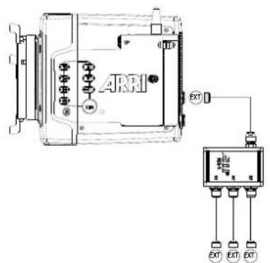
3 Slave Cameras
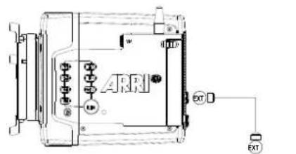
Slave Camera
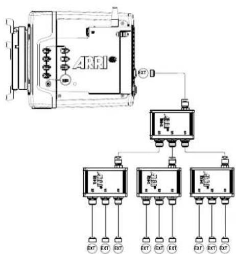
9 Slave Cameras
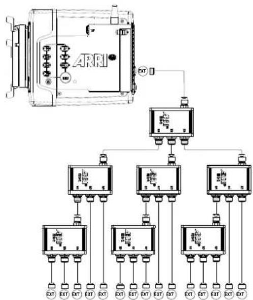
flowchart
graph TD
    A["ARH"] --> B["External Control Unit"]
    B --> C1["Module 1"]
    B --> C2["Module 2"]
    B --> C3["Module 3"]
    C1 --> D1["External Control Unit"]
    C2 --> D2["External Control Unit"]
    C3 --> D3["External Control Unit"]
    D1 --> E1["External Control Unit"]
    D2 --> E2["External Control Unit"]
    D3 --> E3["External Control Unit"]
    E1 --> F1["External Control Unit"]
    E2 --> F2["External Control Unit"]
    E3 --> F3["External Control Unit"]
    F1 --> G1["External Control Unit"]
    F2 --> G2["External Control Unit"]
    F3 --> G3["External Control Unit"]
    G1 --> H1["External Control Unit"]
    G2 --> H2["External Control Unit"]
    G3 --> H3["External Control Unit"]
15 Slave Cameras
ADVICE
- Synchronizing sensors is possible at sensor frame rates between 20 fps and 90 fps.
- The master camera does not distribute look files or frame line files. If custom look files or frame lines are used, the files need to be imported manually on each camera.
EXT Sync Mode
One camera is functioning as the master camera and the other camera(s) as slave camera(s). A slave camera can be a sensor slave (only sensor synchronized) or a settings slave (sensor and settings synchronized).
- Connect the cameras via their EXT connector using the MINI-EXT-sync cable(s) and the EXT Distribution Box EDB-2.
Note: One EDB-2 or more are needed, if the cluster consists of more than two cameras.
- Select MENU > System > Sensor > EXT Sync.
Following options are available:
Off EXT Sync is disabled.
EXT Master Configures the camera as the master camera. The camera has control over
one or more slave cameras. The sensors of all slave cameras will be synchronized to this camera's sensor. All slave cameras will inherit the timecode from this camera.
The master camera can be supplied with external timecode and can be synchronized to an external genlock source.
EXT Sensor Slave
Configures the camera as a sensor slave. The sensor is synchronized with the master camera. The SDI outputs of the slave camera are synchronized with the master camera. The slave camera inherits the timecode from the master camera. Recording starts and stops simultaneously on all cameras.
EXT Settings Slave
Configure the camera as a settings slave. The sensor is synchronized with the master camera. The SDI outputs of the slave camera are synchronized with the master camera. The slave camera inherits the timecode from the master camera. Recording starts and stops simultaneously on all cameras. To ensure an identical clip naming, the slave camera inherits the camera ID from the master camera. Settings synchronized parameters include:
| Project Rate Next Reel Count SDI Frame Rate | |
| Sensor Fps Lens Squeeze Factor SDI Exposure Tool | |
| Shutter and Shutter Unit EVF Processing SDI Peaking | |
| Exposure Index EVF Exposure Tool SDI Overlays | |
| White Balance* EVF Peaking Exposure Tool Settings | |
| ND Filter EVF Overlays | Frame Line Settings |
| Recording Codec | SDI Processing |
| Recording Resolution | SDI Format Noise Reduction |
| Active Look | SDI Color Space |
* White balance: Whenever it is changed on the master camera, the slave cameras will inherit the new setting. The setting inherited from the master camera can anytime be overridden on slave camera(s) by either setting a new value or by executing auto white balance.
Note: Configure all slave cameras first and master camera last.
Note: Parameters can only be changed from the master camera.
- On the master camera in an EXT sync cluster, you need to define the amount of cameras used in the cluster. The master camera monitors the connection to each slave camera.
On the master camera, select MENU > System > Sensor > EXT Sync Camera Count and set the number of cameras used in your cluster (including the master camera, up to 16 cameras).
- When using settings slaves, each camera in the setup needs to use an individual camera ID prefix.
Select MENU > Recording > Project Settings > Camera ID Prefix and select an individual prefix for each camera (usually giving the master camera the camera ID prefix "A")
Media Status with EXT Sync
The master camera calculates the overall remaining recording time based on the media with the lowest capacity in the cluster. The overall remaining recording time is displayed prefixed with EXT on the home screen and in the status info on the master camera.
EXT 0:20:02 REC ARRIRAW LOOK ARRI 709
EXT Sync Info Screen
The EXT sync info screen displays the system status of all cameras in the EXT sync cluster. Information on the camera serial numbers, the camera ID prefixes, the battery voltages and the main status of all cameras are shown.
- Select MENU > Info > EXT Sync Info to access the EXT Sync info screen.
Note: The EXT sync info screen lists the cameras sorted after the camera ID prefix.
Note: If one camera in the cluster is not ready to record, the entire cluster will go into idle state. Use the EXT sync info screen to troubleshoot.
Media Erase in EXT Sync
In EXT sync mode, you can simultaneously erase the cards of all cameras in the cluster:
- On the master camera, select MENU > Media > Erase EXT Sync Media.
A confirmation screen is displayed.
- Press ERASE.
A progress bar indicates the progress of the master camera (only).
- After erasing has finished, press any button to return to the menu.
EXT Sync Clip Naming
When working in EXT sync mode and the slave cameras are configured as settings slaves, clip naming is identical to the use of a single camera.
When working in EXT sync mode and using settings sync, the slave cameras inherit the camera ID of the master camera, so clip file names are identical. To distinguish the clip files from several cameras, the Camera ID prefix is used. For this reason, each camera must use an individual camera ID prefix.
▶ Set the camera ID prefix of each camera in MENU > Recording > Project Settings > Camera ID Prefix.
Note: The master camera will issue an alert in case duplicate camera ID prefixes are used within the setup.
Below is a clip name example for a four camera setup, with three clips recorded. The camera ID prefix is marked in red, the master camera ID is marked in blue. It is recommended to use the same camera index (green) on all cameras.
| A001_AH8B | A001_CH8B |
| A001_C001_190705_AH8B | A001_C001_190705_CH8B |
| A001_C002_190705_AH8B | A001_C002_190705_CH8B |
| A001_C003_190705_AH8B | A001_C003_190705_CH8B |
| A001_BH8B | A001_DH8B |
| A001_C001_190705_BH8B | A001_C001_190705_DH8B |
| A001_C002_190705_BH8B | A001_C002_190705_DH8B |
| A001_C003_190705_BH8B | A001_C003_190705_DH8B |
Note: Do not mix sensor and settings slaves as this will cause inconsistencies in clip naming.
19.2 Genlock Synchronization
The camera's sensor and SDI outputs can be synchronized to a reference sync signal (a tri-level HD signal or an analog black burst signal) using the SYNC IN BNC connector. The camera's sensor needs to run at equal or double the frame rate of the reference signal to establish synchronization.
Activation of Genlock
- Connect the genlock source to the cameras SYNC IN connector.
- Ensure that the camera's sensor frame rate matches (or is double) the genlock source frame rate.
- Set MENU > System > Sensor > Genlock Sync to SYNC IN.
GEN
With Genlock Sync activated, the camera displays a genlock icon on the HOME screen and in the status info of EVF/Monitor and the SDI outputs. The icon turns orange when the camera can not synchronize to the genlock signal or if no signal could be detected. In this case, see MENU >Alerts for detailed information.
Note: Simultaneous use of Timecode mode Jam-sync and Genlock is not supported.
Sync Shift
The Sync Shift option applies an offset to the genlock signal at the input. Minimum step size is 52 ns, maximum possible correction is up to +/- 20 ms (= 384000 steps), depending on the sensor frame rate.
▶ Select MENU > System > Sensor > Sync Shift and apply the needed sync shift.
19.3 Timecode Synchronization
The camera's sensor and SDI outputs can be synchronized to a reference timecode signal using the 5-pin TC connector. The camera's sensor needs to run at equal or double the frame rate of the reference signal to establish synchronization.
Activation of Timecode Synchronization
- Connect the timecode source to the cameras TC connector.
- Ensure that the camera's sensor frame rate matches (or is double) the timecode source frame rate.
- Set MENU > System > Sensor > Genlock Sync to TC IN.
GEN
With Genlock Sync activated, the camera displays a genlock icon on the HOME screen and in the status info of EVF/Monitor and the SDI outputs. The icon turns orange when the camera can not synchronize to the genlock signal or if no signal could be detected. In this case, see MENU > Alerts for detailed information.
Note: Simultaneous use of Timecode mode Jam-sync and Genlock is not supported.
20 Sensor Settings
20.1 Noise Reduction
ARRI Noise Reduction ANR-1
ARRI Noise Reduction ANR-1 is implemented in most modern ARRI camera models and can be used for monitoring purposes on set, recording to MXF/Apple ProRes files (baked in) or as metadata of MXF/ARRIRAW recordings with full flexibility to change the parameter in postproduction. ARRI Noise Reduction ANR-1 can be helpful in low light situations to reduce noise in the images. While it is commonly available in postproduction tools, two reasons drove us towards creating a new, in-camera ARRI noise reduction: we enable fast, in-camera noise reduction and we provide a noise reduction method that retains the grain texture and natural looks that ARRI customers like.
Using ARRI Noise Reduction ANR-1 enables you to use noise reduction on set in the camera. This can be helpful for low light shots, where an in-camera noise reduction is a very fast solution. Furthermore, ARRI Noise Reduction ANR-1 gives you the possibility to combine the amount of grain with your sharpness and detail settings for the chosen exposure directly on set.
You can store your decision either in the metadata, when recording MXF/ARRIRAW or bake it into Apple ProRes files. In contrast to general postproduction tools, the ARRI Noise Reduction ANR-1 is optimized for the sensor noise characteristics and therefore can achieve a very natural noise reduction without any image blurring. This noise reduction, optimized for the ARRI sensors is available for ARRIRAW recordings by using the ARRIRAW Converter or a post-processing software that incorporates the ARRIRAW SDK. The film grain like texture of ARRI cameras is highly appreciated by cinematographers around the world and therefore ARRI Noise Reduction ANR-1 is moderate and does not affect the grainy structure of the noise. The ARRI Noise Reduction ANR-1 just reduces it, nothing more.
For more information please refer to the ARRI Texture Control White Paper, available in the White Papers section on the ARRI website.
▶ Select MENU > System > Sensor > Noise Reduction to toggle noise reduction on/off.
Note: While recording MXF/Apple ProRes files, noise reduction will be baked into the footage and therefore MXF/Apple ProRes files cannot be opened and altered in the ARRIRAW Converter (ARC).
When recording MXF/ARRIRAW files, the ARRI Noise Reduction ANR-1 is applied for preview (viewfinder and SDI outputs) but not baked into the footage, instead it will be stored in metadata.
20.2 Mirroring the Sensor Image
You can mirror the sensor image in horizontal and vertical directions.
▶ Select MENU > System > Sensor > Mirror Image.
You have the following options:
Off Mirroring is inactive.
V The sensor image is vertically mirrored.
H The sensor image is horizontally mirrored.
V+H The sensor image is vertically and horizontally mirrored (rotated by 180^ ).
Horizontal mirroring is applied on all output paths and internally recorded material. Vertical mirroring is only applied to output paths; internally recorded material is not rotated, but rotation information is written into metadata. Frame grabs of rotated images will be displayed upside down on a computer.
20.3 User Pixel Masking
All sensors exhibit a certain number of defect pixels, and ARRI cameras have two mechanisms to catch and correct them: one is a static pixel correction based on a pixel mask created during manufacturing, and the other is a dynamic pixel correction that continuously evaluates each frame and masks defect pixels that are not caught by the static pixel mask. In very few cases, we have observed some pixels that are not corrected by either method; for those cases User Pixel Masking is available.
User pixel masks can be created with the ARRIRAW Converter available for macOS, Windows and Ubuntu.
When shooting ARRIRAW, it is not necessary to load the User Pixel Mask into the camera. Instead, it can be applied to the ARRIRAW files in post using the ARRIRAW converter or any third party software that has implemented the User Pixel Mask feature through our ARRIRAW SDK.
The User Pixel Mask will remain intact after a factory reset and after a camera software update. It can be manually removed or overwritten with a new one at any time.
- Select MENU > System > Sensor > User Pixel Masking.
Following options are available:
User Pixel Mask Active Shows whether a User Pixel Mask is currently active in the camera.
Install User Pixel Mask Select to install a User Pixel Mask from USB memory stick.
Export User Pixel Mask Select to backup the currently installed User Pixel Mask onto USB memory stick.
Delete User Pixel Mask Select to uninstall a User Pixel Mask.
Grab Raw Image Stores an ARRIRAW frame grab on the USB memory stick.
User Pixel Mask Generation
- Insert a USB memory stick into camera.
- Select MENU > System > Sensor > User Pixel Masking > Grab Raw Frame to grab an ARRIRAW frame.
The ARRIRAW frame grab is stored on the USB memory stick in folder ARRI/A-MINI-LF/SENSOR. Alternatively, you can record a short ARRIRAW sequence and use that material for marking defect pixels.
- Import the ARRIRAW frame grab into the ARRIRAW Converter.
- Use the ARRIRAW Converter to mark defect pixels. The marked pixel coordinates are stored in an XML file called the User Pixel Mask. Please note that it is advisable to mark the least number of pixels necessary, as too many marked pixels can be counter productive.
- Save the User Pixel Mask to the USB memory stick in folder ARRI/A-MINI-LF/SENSOR.
- Insert the USB memory stick into the camera.
- Select MENU > System > Sensor > User Pixel Masking > Install User Pixel Mask to load the mask into the camera.
- After a restart of the camera, the marked pixels will be masked using information from surrounding pixels. This masking is applied to the images delivered from the sensor, before any other processing takes place, and thus becomes active on all outputs.
- Carefully check the end result by visually inspecting the areas where you have marked pixels; if too many pixels are marked too close to each other, or if pixels are marked close to other pixels that are already marked in the static pixel mask, the result could be uncorrectable clusters, which are more visible than the original defect pixels.
As an added service, it is possible to send the User Pixel Mask to ARRI Service at service@arri.de for verification. We strongly recommend that you take advantage of this free service, as sometimes, clusters are difficult to spot depending on the background. Please note, however, that in the end, it is the responsibility of the person creating the User Pixel Mask to verify that no clusters are formed.
ADVICE
Please note, that the User Pixel masking feature is only a temporary solution to mask defect pixels. Defect pixels should be dealt with by sensor calibration at an ARRI service department.
A User Pixel Mask is a stopgap solution between when the defect is noticed, and when the camera is recalibrated, to verify the sensor is still functioning within ARRI specifications and to comprehensively assess and permanently and automatically compensate for defect pixels.
If the installed pixel masking map is deleted, the camera will be reset to its old status with all defect pixels.
21 System Settings
21.1 Language Setting
- Select MENU > System > Language.
- Set the language to either English or Chinese (simplified).
21.2 System Time and Date
▶ Select MENU > System > System Time + Date to set the system time and date.
Note: Timezone and Daylight Saving Time do not change time and date settings. They are stored as metadata in the recorded clips.
21.3 Button and Display Settings
▶ Select MENU > System > Buttons + Display.
Following options are available:
Display Style
Choose between day mode and night mode.
Button Brightness
Adjust the brightness of camera and MVF buttons from 0 to 4 (0 = off)
21.4 Fan Settings
Select to set the fan mode to Low Noise for locations with ambient temperatures up to 30^ C ( 86^ F). For locations with ambient temperatures higher than 30^ C ( 86^ F), set to Rec Low. When the fan is set to Rec Low, it will run at a high rate when the camera is in Standby, and run at a low rate when the camera is recording.
▶ Select MENU > System > Fan Mode.
Following options are available:
Rec Low Increases fan speed during standby to cool the camera. Minimizes fan speed/noise during recording.
Note: Ideal in an environment warmer than 30 °C (86 °F).
Low Noise Minimizes fan noise during standby and recording.
Note: With data rates above 100 MB/s (due to fps/codec setting), the fan speed automatically increases to prevent the recording media from overheating.
21.5 Battery Warning
You can adjust the voltage level at which a power warning is displayed for the power source connected to the BAT connector. The level can be adjusted to match the battery type used. The default warning value is 13.5 V.
▶ Select MENU > System > Power > BAT In Warning and set the warning level between 11.0 V and 34.0 V.
When the power source reaches the defined voltage level the battery display on the HOME screen and in the status info of the viewfinder and SDI outputs start flashing.
21.6 Lens Mount Settings
You can enable/disable the LDS contacts of the lens mount and set your preferred focus unit.
- Select MENU > System > Lens Mount Settings.
Following settings are available:
Focus Unit
Set the unit for display of the lens focus distance to Lens Default, Metric or Imperial.
Enable Lens Mount Enable/disable the lens contacts of a PL or EF lens mount.
ADVICE
Please note that as soon as an LDA table is activated, the LDS contacts of the lens mount are switched off. There is no need to switch the mount off manually when using LDA.
21.7 Network and WiFi Settings
WiFi Settings
The WiFi module in the ALEXA Mini LF can be configured to act as an access point or in infrastructure (client) mode and opens up a wireless network in the 2.4 GHz band. A WiFi connection can be used to remote control the camera using the camera's web remote or applications communicating with the camera via the Camera Access Protocol (CAP).
The camera is equipped with two WiFi antennas, one external antenna above the media bay (1) and one internal antenna on the right side front (2).
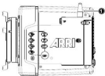
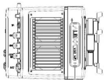
natural_image
Technical line drawing of an industrial electrical device with cooling fins and a control panel (no text or symbols)2
WiFi Power
▶ Select MENU > System > Network / WiFi > WiFi Power and set WiFi power on or off.
Additionally to the WiFi settings menu, WiFi power can be toggled by using the FN function button or a user button assigned with WiFi Power.
External Antenna
▶ Select MENU > System > Network / WiFi > External Antenna to enable or disable WiFi radio for the external antenna.
Note: Wifi External Antenna can only be disabled (or re-enabled) when Wifi Power is off. Once Wifi External Antenna is disabled (or re-enabled) Wifi Power is initially grayed out and can only be activated after about 3 seconds.
WiFi Mode
- Select MENU > System > Network / WiFi > WiFi Mode.
Following options are available:
Host The camera acts as an WiFi access point. The SSID of the camera is "Mini-LF-SERIAL#", where SERIAL# is the five digit serial number of the camera.
Client The camera can connect to a WiFi network and receives it's IP address via DHCP.
- Set the desired WiFi mode.
Note: the WiFi mode can only be changed while WiFi power is disabled.
WiFi Host Channel
- Select MENU > System > Network / WiFi > WiFi Host Channel.
- Select Automatic to have the camera automatically select the WiFi host channel with the best performance, or select a WiFi channel between 1 and 11.
With the Automatic setting, the camera will re-discover the best WiFi host channel every time it is rebooted. Select Automatic from the list again to trigger a new scan. The selected channel is displayed in brackets.
When using WiFi and White Radio simultaneously, and setting the WiFi Host Channel manually, it is important to configure the used channels to avoid interference and guarantee optimal performance.
The following table gives an overview of suitable channel configurations:
| WiFi Channel | ARRI White Radio Channel Number | |||||||||||||
| 0 | 1 | 2 | 3 | 4 | 5 | 6 | 7 | 8 | 9 | 10 | 11 | 12 | 13 | |
| 1 | × | × | × | × | √ | √ | √ | √ | × | × | √ | √ | √ | √ |
| 2 | × | × | × | × | √ | √ | √ | √ | × | × | × | √ | √ | √ |
| 3 | × | × | × | × | √ | √ | √ | √ | × | × | × | × | √ | √ |
| 4 | × | × | × | × | √ | √ | √ | √ | × | × | × | × | √ | √ |
| 5 | × | × | × | × | × | × | √ | √ | × | × | × | × | √ | √ |
| 6 | √ | × | × | × | × | × | √ | √ | × | × | × | × | × | √ |
| 7 | √ | √ | × | × | × | × | √ | √ | × | × | × | × | × | × |
| 8 | √ | √ | × | × | × | × | × | √ | √ | × | × | × | × | × |
| 9 | √ | √ | × | × | × | × | × | × | √ | √ | × | × | × | × |
| 10 | √ | √ | √ | × | × | × | × | × | √ | √ | × | × | × | × |
| 11 | √ | √ | √ | √ | × | × | × | × | √ | √ | × | × | × | × |
| 12 | 13 | 16 | 17 | 20 | 21 | 24 | 25 | 14 | 15 | 18 | 19 | 22 | 23 | |
| ZigBee IEEE 802.15.4 Radio Channel Number | ||||||||||||||
WiFi Password (Host Mode)
The camera uses WPA-2 encryption. You can only set the WiFi host password if the WiFi mode is set to Host. The default password for the network is set to "arriarri". For security reasons, we recommend that you do not use the default password, but assign your own password.
- Select MENU > System > Network / WiFi > WiFi Host Password.
A screen is displayed to set your password.
- Enter a password. The WiFi password must be between 8 and 32 characters long.
Connect to a Network (Client Mode)
You can select a WiFi network, if you have activated the WiFi power and when the WiFi mode is set to Client. The camera allows you to join networks with WPA2 encryption or without encryption.
- Select MENU > System > Network / WiFi > WiFi Network > WiFi Networks Available.
A list of available WiFi networks is displayed.
- Select the WiFi network the camera should connect to.
If the selected WiFi network uses encryption, you are prompted to enter the password.
- Enter the password and press CONNECT.
Note: Connection to networks using WPA encryption is not supported.
Connect to a Network using a QR Code (Client Mode)
You can use a QR code to connect to a WiFi network. The WiFi credentials need to be provided in the following format:
WIFI:S:my-ssid;T:[WEP|WPA|WPA2];P:my-password;;
where the italic parts need to be replaced with your network credentials.
- Select MENU > System > Network / WiFi > WiFi Network > SCAN QR.
- Hold the QR-Code in front of the lens so that it fills the frame and is in focus.
A popup window with QR-Code data is displayed.
- Press CONNECT.
The camera connects with the network. The name of the network is displayed in the WiFi NETWORKS AVAILABLE list.
Disconnect from Network (Client Mode)
- Select MENU > System > Network / WiFi > WiFi Network.
- Press DISCONNECT.
If the network you were connected to is hidden, it will disappear from the network list shortly after.
WiFi Status Icons on HOME Screen and in Status Info
With WiFi power enabled, the WiFi status is indicated by an icon on the "home screen" and the "status info" of the viewfinder and the SDI outputs:

Host mode icon. WiFi power is enabled and WiFi mode is set to Host.

Client mode icon. WiFi power is enabled and connection to network has been established.

Client mode icon. WiFi power is enabled but camera is not connected to a network.
Additional information can be found under MENU > Info > Network Info.
LAN Settings
Use the ALEXA Ethernet cable (KC 153-S, K2.72021.0) to connect the camera to a router or other devices.
LAN IP Mode
- Select MENU > System > Network / WiFi > LAN IP Mode.
Following options are available:
Static Select for manually entering an IP address and subnet mask.
DHCP Select to let the camera accept a dynamically assigned IP address from an DHCP server.
- Set the desired LAN IP mode.
LAN Static IP
- Select MENU > System > Network / WiFi > LAN Static IP.
- Set the desired LAN Static IP adress.
LAN Static Subnet
- Select MENU > System > Network / WiFi > LAN Static Subnet.
- Set the desired LAN Static subnet.
21.8 Reset of Electronic Horizon
- Select MENU > System > Reset Electronic Horizon.
A screen showing the roll and tilt values is displayed.
- Place the camera on a level surface and press RESET.
Note: A message is displayed if either the roll, the tilt or both values exceed the calibration range and resetting is not possible.
21.9 Camera Update
21.9.1 Update of Camera Software
The camera software is updated with a USB memory stick. The Software Update Package (SUP) will update the camera along with the Viewfinder MVF-2 and the lens mount – provided they are connected to the camera.
The Software Update Package (SUP) can be found in the Software and Firmware Updates for Cameras section on the ARRI website. You need to register your camera, along with your camera serial number, to access the SUP download. Existing ALEXA customers with an active account for the download section can use this account, unless otherwise requested.
Before update, create the folder structure on a FAT 32 USB memory stick. For more information, see "Prepare User Storage for Use", page 50.
ADVICE
Power the camera with a fully charged battery or a power supply to avoid power loss during the update. The update procedure takes about ten minutes.
Never shut down the camera or unplug power during the update process.
After the update, the camera reboots. Never unplug power during reboot. Check the MVF-2 for the update status. A popup message is displayed after the update finished successfully.
After a camera update, the Web Remote feature may not be fully functional until the browser cache of your web browser has been cleared. Always use a 'private' or 'incognito' browser window when using the Web Remote to operate the camera and to perform a SUP update. This prevents possible erroneous behavior.
21.9.2 Update of Camera Components
The camera supports to update the MVF-2 viewfinder and the lens mount. Updating the MVF-2 and the lens mount does not require a dedicated update file. The camera will issue a message if the software version of MVF-2 and/or the lens mount does not match the version required by the currently installed camera SUP. In this case:
- Select MENU > System > Update.
The Update MVF-2 and Update Lens Mount entries show the software version currently installed on the component and the software version required by the currently installed camera SUP.
- Select Update MVF-2 to update the MVF-2 or
Select Update Lens Mount to update the lens mount.
A confirmation screen is displayed.
- Press CONFIRM to start the update.
The component is updated. A success message is displayed after the update has finished.
21.9.3 Update of LBUS Devices
The camera offers to update connected LBUS devices (cforce mini motors, cforce Plus motors, ARRI Master Grips, ARRI Operator Control Unit OCU-1 and ARRI LCUBE)
- Download the LBUS device update file from the ARRI website.
- Copy the update file onto a USB memory stick in folder ARRI/ECS/.
- Connect the LBUS device to the LBUS connector of the lens mount.
- Select MENU > System > Update > Update LBUS Devices.
A list with connected LBUS devices is displayed, showing the software version currently installed on the device and the software version stored on the USB memory stick.
- Select the LBUS device you want to update and press UPDATE.
A confirmation screen is displayed.
- Press CONFIRM to start the update. Cancel with BACK.
22 User Setups
A user setup is a profile of the current settings on the camera that can be saved on camera and/or to a USB memory stick. User setups can be given custom names, saved to the USB memory stick and loaded onto multiple cameras. Rather than resetting the camera to its factory default settings, a user setup can be used to reset the camera to a user's default settings.
User setups can be used to ensure that cameras on multi-camera shoots have matching settings, or to transfer a show's setup onto daily cameras, to ensure they carry the same shooting specifications.
Saving a User Setup
You can save the current setup configuration in the camera or on the USB medium.
- Select MENU > Setup > User Setups Installed > Save to save the setup in the camera.
Select MENU > Setup > User Setups on USB > Save to save the setup on the USB medium.
- Use the onscreen keyboard to enter a name for the user setup and press SAVE.
A screen is displayed to select the setup parameter blocks. You have the following options:
- General
- Format
- Scene
- Lens
-
User
-
Select one or more options and press CONFIRM.
The camera stores the user setup.
Loading a User Setup
You can load user setups stored on the camera or on a USB medium.
In case you are using the ARRI WCU-4 unit, you can trigger the loading of internally stored setups from there.
-
Select MENU > Setup > User Setups Installed to load a setup from the camera.
Select MENU > Setup > User Setups on USB to load a setup from the USB medium. -
Select a user setup from the list and press LOAD.
A popup window with the parameter blocks of this user setup is displayed.
- Press CONFIRM.
The camera loads the selected user setup and shows a result message. The popup highlights the parameters that you should check in case certain parameters could not be loaded.
Factory Reset
You can reset the camera to the ARRI factory default values.
- Select MENU > Setup > Factory Reset.
A confirmation popup window is displayed.
- Press RESET.
The camera settings are reset to factory defaults.
Note: A factory reset does not delete user setups stored/installed on camera.
22.1 User Setup Parameter Blocks
The camera allows you to store a full camera configuration by selecting all parameter blocks, or only parts of the configuration by de-/selecting the desired blocks. The parameter blocks have been chosen to allow for maximum flexibility while keeping coherent sets of parameters and minimizing the amount of potential conflicts by loading partial setups.
GENERAL
Groups the general camera configuration and basic project settings.
MENU > RECORDING > PROJECT SETTINGS > Project Rate
HOME > TC > OPTIONS > Timecode Options (All Settings)
MENU > RECORDING > AUDIO RECORDING > Audio (All Settings)
MENU > LOOK > LOOK > Installed Look Files
MENU > LOOK > SDI 1&2 Color Space
MENU > MONITORING > FRAME LINES > FRAME LINE > Installed Frame Line Files
HOME > FPS > Sensor FPS table
HOME > SHUTTER > Shutter table
HOME > WB > WB table
MENU > METADATA > Metadata (All Settings)
MENU > MONITORING > SDI > SDI 1&2 Format
MENU > MONITORING > SDI > SDI 1&2 Frame Rate
MENU > MONITORING > SDI > SDI 1&2 Image
MENU > MONITORING > SDI > SDI 1&2 3G Level
MENU > MONITORING > SDI > SDI2: Clone SDI1
MENU > MONITORING > SDI > Anamorphic Desqueeze
MENU > SYSTEM > SENSOR > Noise reduction
MENU > SYSTEM > SENSOR > Mirror Image
MENU > SYSTEM > SENSOR > EXT Sync
MENU > SYSTEM > SENSOR > EXT sync camera count
MENU > SYSTEM > SENSOR > Genlock Sync
MENU > SYSTEM > SENSOR > Sync Shift
MENU > SYSTEM > SENSOR > Mirror Image
MENU > SYSTEM > Fan Mode
MENU > SYSTEM > CAP Settings
MENU > ECS > RADIO > ECS Power
MENU > ECS > RADIO > ECS Radio Channel
FORMAT
Allows for easy switching between recording formats.
MENU > RECORDING >
MENU > RECORDING >
Recording Codec
recording Resolution
MENU > MONITORING > FRAME LINES > Active frame line*
*if not found in list, load NONE
SCENE
Allows you to change quickly between different shooting situations.
HOME > FPS Sensor FPS
HOME > SHUTTER Shutter
HOME > EI Exposure Index
HOME > WB White Balance
HOME > ND ND Filter
MENU > LOOK Active Look*
*if not found in list,
then load ARRI709
HOME > EI > IRIS EF Iris Value
LENS
Allows you to change quickly between different lens setups.
MENU > RECORDING > PROJECT SETTINGS > Lens Squeeze Factor
MENU > ECS > LENS DATA > Active Lens Table
MENU > ECS > LENS DATA > Lens Tables Installed
MENU > ECS > LENS DATA > Lens Table Favorites
MENU > ECS > LBUS LENS MOTOR CONFIG > Focus Lens motor direction, torque + teeth count
MENU > ECS > LBUS LENS MOTOR CONFIG > Iris Lens motor direction, torque + teeth count
MENU > ECS > LBUS LENS MOTOR CONFIG > Zoom Lens motor direction, torque + teeth count
MENU > SYSTEM > LENS MOUNT SETTINGS > Focus Unit
USER
Stores all parameters for camera personalization.
MENU > LOOK > EVF/Mon. Processing
MENU > LOOK > SDI 1 & 2 Processing
MENU > MONITORING > EVF / Monitor > Surround View
MENU > MONITORING > EVF / Monitor > Peaking Settings
MENU > MONITORING > EVF / Monitor > Settings (all, except EVF power)
MENU > MONITORING > EVF / Monitor > EVF Overlays (all settings)
MENU > MONITORING > EVF / Monitor > Monitor Overlays (all settings)
MENU > MONITORING > SDI > SDI PROCESSING > Surround View
MENU > MONITORING > SDI > SDI PROCESSING > Peaking (all settings)
MENU > MONITORING > SDI > SDI PROCESSING > Overlays (all settings)
MENU > MONITORING >
Exposure Tools (all settings)
MENU > USER BUTTONS > User Buttons (all settings)
MENU > SYSTEM > POWER > Bat In Warning
MENU > SYSTEM > BUTTONS + DISPLAY > Display Style, Button Brightness
PLAY > OPTIONS > Play End mode
MENU > RECORDING > REC BEEPER / TALLY > All Settings
Note: Network settings are not stored in the user setup.
23 User Buttons
Camera User Buttons
The camera is equipped with six freely assignable user buttons (1). Each button can be customized with individual functions. Once a user button is assigned with a function, press the button to trigger its function. An LED on each user button reflects the functional status. Note: Camera user buttons 7 and 8 can only be triggered using the Web Remote.
- Select MENU > User Buttons > Camera User Buttons.
- Select the button you want to customize.
- Assign the desired function from the list to the button.
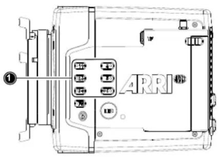
MVF-2 User Buttons
The MVF-2 is equipped with two user buttons, VF1 and VF2 (1). Each button can be customized with individual functions:
- Select MENU > User Buttons > Button VF1 or select MENU > User Buttons > Button VF2.
- Assign the desired function from the list to the button.
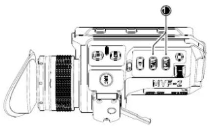
Additional User Buttons
In addition to camera and MVF-2 user buttons the camera supports to configure the user buttons of electronic accessories such as the Wireless Compact Unit WCU-4, ARRI Master Grips, Operator Control Unit OCU-1 and the GPIO box.
- Select MENU > User Buttons.
- Select the accessory to configure:
WCU User Buttons Up to 6 user buttons can be assigned with functions to be used with the Wireless Compact Unit WCU-4.
LBUS Device User Buttons Up to 12 user buttons can be assigned with functions to be used with the ARRI Master Grips and the Operator Control Unit OCU-1.
GPIO User Buttons The ARRI GPIO box (GPB-1, K.2.0007642) can be used as an interface to the camera for external user buttons. It connects to the camera via the EXT connector and has a 37-pin D-Sub connector carrying 14 GPI (General purpose input) connections plus 2 outputs (camera power status and camera recording status). For additional information, please refer to the user manual of the GPB-1. Up to 14 user buttons can be assigned for the GPIO box.
- Select the button you want to customize.
- Assign the desired function from the list to the button.
Smart Behavior
Some user button functions support smart behavior. For these, a short press (i.e. less than half a second) toggles the function, while a long press (i.e. longer than half a second) activates the function only temporarily, as long as the user button is pressed. Assume a user button is configured with EVF Zoom:
▶ Short press of user button: EVF zoom is activated and stays activated. Press again to deactivate.
▶ Long press of user button: EVF zoom function is activated while you are pressing the button, release of the button deactivates EVF zoom.
User Button Info Screen
The camera offers a user button info screen showing the current assignment of the camera user buttons as well as the MVF-2 user buttons.
▶ Select MENU > Info > User Button Info to view the current user button configuration of camera and MVF-2 user buttons.
23.1 List of User Button Functions
Following user button functions are available:
| User Button Functions | |
| Off Disables the user button. | |
| EVF Status Info | Toggles display of EVF status info between Safe, Off and Overlay. |
| EVF+Mon. Check Log C Temporarily set EVF/Monitor processing to Log C. Supports smart behaviour. | |
| EVF+Mon. Desqueeze Toggles | anamorphic desqueeze on EVF and Monitor on/off. |
| EVF+Mon. Exp. Tool | Switches the exposure tool on or off on EVF and Monitor. Supports smart behavior. |
| EVF+Mon. Frame Lines | Switches frame lines on or off on EVF and Monitor. Supports smart behavior. |
| EVF+Mon. Peaking Switches peaking on or off on EVF and Monitor. Supports smart behavior. | |
| EVF+Mon. Surround Switches surround view on or off on EVF and Monitor. Supports smart behavior. | |
| EVF+Mon. Zebra/FC Toggles the exposure tool for EVF and Monitor between Zebra and False Color. | |
| EVF+Mon. Zoom Switches the viewfinder zoom function on or off. Supports smart behavior. | |
| Flip Monitor Toggles the Monitor between normal and flipped mode.To return to automatic operation, press and hold the user button for two seconds. | |
| SDI Check Log C | Temporarily set SDI processing to Log C. Supports smart behaviour. |
| SDI Desqueeze Toggles anamorphic desqueeze on the SDI outputs on/off. | |
| SDI Exp. Tool | Switches the exposure tool on or off on the SDI outputs. Supports smart behavior. |
| SDI Frame Lines | Switches frame lines on or off on the SDI outputs. Supports smart behavior. |
| SDI Peaking | Switches peaking on or off on the SDI outputs. Supports smart behavior. |
| SDI Status info | Toggles SDI status info between Safe, Overlay and Off |
| SDI Surround | Switches surround view on the SDI outputs on or off. Supports smart behavior. |
| SDI Zebra/FC | Toggles the exposure tool for the SDI outputs between Zebra and False Color. |
| SDI Zoom | Switches the SDI zoom function on or off. Supports smart behavior. |
| SDI Zoom Position | Toggles the SDI zoom position. |
| User Button Functions | |||
| SDI Zoom (smart) Press SDI Zoom to activate the zoom function on the SDI outputs. Further button presses change the Zoom position. A button longpress exits the Zoom function. | |||
| EI Increase Selects the next value from the EI (exposure index) list. | |||
| EI Decrease Selects the previous value from the EI (exposure index) list. | |||
| FPS Increase Selects the next value from the FPS list. | |||
| FPS Decrease Selects the previous value from the FPS list. | |||
| ND Increase Selects the next value from the ND list. | |||
| ND Decrease Selects the previous value from the ND list. | |||
| Shutter Increase Selects the next value from the Shutter list. | |||
| Shutter Decrease Selects the previous value from the Shutter list. | |||
| WB Increase Selects the next value from the WB list.Note: User button skips the Auto WB entry of the WB list. | |||
| WB Decrease Selects the previous value from the WB list.Note: User button skips the Auto WB entry of the WB list. | |||
| Audio Ch1 Increase Increases gain of audio channel 1 in 1dB steps.Note: User button is only functional with channel 1 control set either to Manual or Manual (+L). | |||
| Audio Ch1 Decrease Decreases gain of audio channel 1 in 1dB steps.Note: User button is only functional with channel 1 control set either to Manual or Manual (+L). | |||
| Audio Ch1+2 Increase Increases gain of audio channels 1+2 simultaneously in 1dB steps.Note: User button is only functional with channel 1 and channel 2 control set either to Manual or Manual (+L). | |||
| Audio Ch1+2 Decrease Decreases gain of audio channels 1+2 simultaneously in 1dB steps.Note: User button is only functional with channel 1 and channel 2 control set either to Manual or Manual (+L). | |||
| Auto WB | First press arms auto white balance for one second, second press triggers AWB. | ||
| Check Last Clip | Plays the last five seconds of the last recorded clip. | ||
| Color Bars | Turns color bar on or off. Activation works only during Stby. | ||
| Frame Grab | Grabs a Log C still frame in .JPG and .DPX format and saves it to the USB medium in the GRABS directory. Frame grabs can be stored when the camera is in STBY, REC or PLAY.When triggered, the frame grab icon displayed on the home screen as well as the status info of the viewfinder and the SDI outputs reflects the frame grab status: White: Frame grab is stored to USB.Orange: Frame grab failed.Note: Frame grabs are taken from the SDI image path (including SDI settings such as processing, active look and anamorphic desqueeze) but cropped to the active image area (without black borders). The frame grab resolution depends on the SDI format (HD / UHD): White: Frame grab is stored to USB.Orange: Frame grab failed.Note: Frame grabs are taken from the SDI image path (including SDI settings such as processing, active look and anamorphic desqueeze) but cropped to the active image area (without black borders). The frame grab resolution depends on the SDI format (HD / UHD): | ||
| Recording Resolution | Grab Resolution (SDI = HD) | Grab Resolution (SDI = UHD) | |
| LF Open Gate 4.5K | 1547 x 1076 | 3094 x 2153 | |
| LF 2.39:1 | 1906 x 795 | 3812 x 1590 | |
| LF 16:9 UHD/HD/2K | 1920 x 1080 | 3840 x 2160 | |
| User Button Functions | |
| Frame Line Color Changes the | frame line color. |
| Iris Auto Only for use with EF lenses. Triggers automatic iris. | |
| Iris Close | Only for use with EF lenses. Closes the iris of a lens. Short press closes by 1/x stop (step size depending on lens), long press closes by 1 stop per 0.5 seconds. |
| Iris Open | Only for use with EF lenses. Opens the iris of a lens. Short press opens by 1/x stop (step size depending on lens), long press opens by 1 stop per 0.5 seconds. |
| Button FN Behaves identically to | FN button on camera body.Note: Only available for GPIO box and Master Grip user buttons. |
| Button 1 to Button 3 | Behaves identically to button 1, button 2 or button 3 on camera body.Note: Only available for GPIO box and Master Grip user buttons. |
| Overlay Menu | Activates or deactivates the overlay menu on MVF-2 EVF, monitor and SDI (when SDI processing is activated). |
| Playback Behaves identically to | the PLAY button on MVF-2. |
| Record Start/Stop Behaves identically to the REC button. | |
| WiFi Power Toggles WiFi power | On and Off. |
24 Metadata
An ARRI camera automatically collects metadata when shooting. This metadata is stored in the header of recorded MXF/Apple ProRes and MXF/ARRIRAW files. The data is also stored in separate Avid Log Exchange ALE files, which keep track of all statics that are recorded on one recording media. Additionally, ARRI cameras can record lens data dynamically frame-by-frame. Static and dynamic metadata can be extracted e.g. from all recording formats by using ARRI Meta Extract, a free ARRI tool.
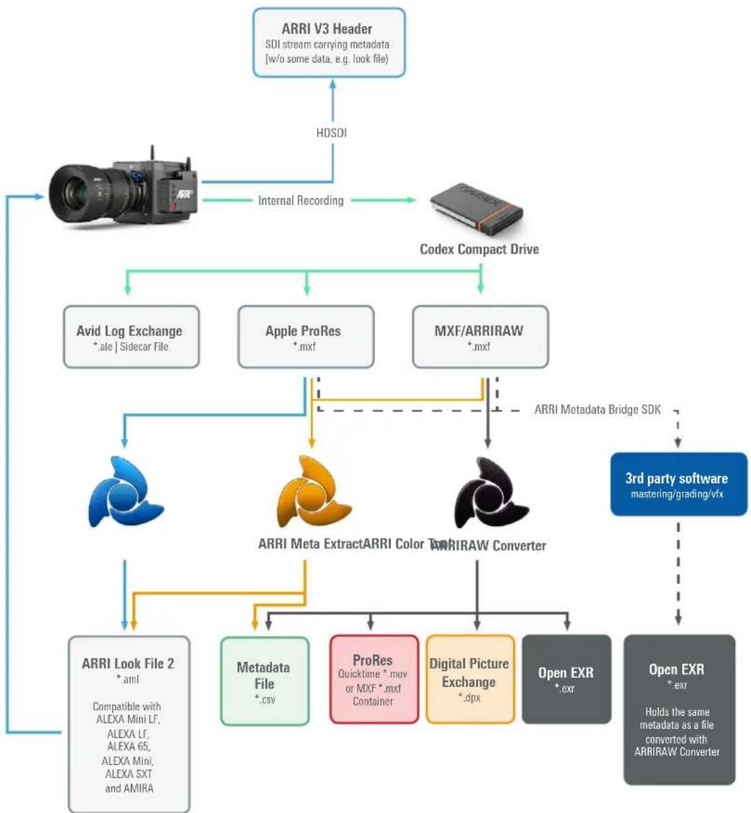
flowchart
graph TD
    A["ARRI V3 Header\nSDI stream carrying metadata\n[w/o some data, e.g. look file)"] --> B["HDSDI"]
    B --> C["Internal Recording"]
    C --> D["Codex Compact Drive"]
    D --> E["Avid Log Exchange\n*.ale | Sidecar File"]
    D --> F["Apple ProRes\n*.mxf"]
    D --> G["MXF/ARRIRAW\n*.mxf"]
    E --> H["ARRI Meta Extract ARRI Color T-ARRIRAW Converter"]
    F --> H
    G --> H
    H --> I["ARRI Look File 2\n*.aml\nCompatible with ALEXA Mini LF, ALEXA LF, ALEXA 65, ALEXA Mini, ALEXA SXT and AMIRA"]
    H --> J["Metadata File\n*.csv"]
    H --> K["ProRes\nQuicktime *.mav or MXF *.mxf Container"]
    H --> L["Digital Picture Exchange\n*.dpx"]
    H --> M["Open EXR\n*.exr"]
    H --> N["Open EXR\n*.exr\nHolds the same metadata as a file converted with ARRIRAW Converter"]
    N --> O["3rd party software\nmastering/grading/vfx"]
    O --> P["ARRI Metadata Bridge SDK"]
    P --> H
The most important metadata for post production workflow is the tape name, as it will be one of the primary identifiers used in the EDL. The term tape name is an existing post-production naming convention that is also used for nonlinear media. The terms tape name and reel name may be used interchangeably. The tape name of ALEXA files is limited to 8 letters to match the CMX 3600 EDL standard. It consists of the camera index, reel counter and the camera ID. Based on the previous example, the tape name of the clip would be A004R18T. Even if the user forgets to assign different camera indices to two cameras on the same project, the camera ID metadata guarantees unique tape names.
In post-production, lens data and other metadata can be accessed and visualized directly in the ARRIRAW Converter. ARRI Meta Extract on the other hand is able to export all metadata, audio as well as look files from any ARRI original camera negative. The third option is the so called ARRI Metadata Bridge (AMB), a software development kit, which can be implemented by 3rd parties to gain direct
access to the embedded metadata in their tools. Through AMB we're closely working with VFX tool manufacturers for years now to enable and enhance their systems to auto-sense e.g. lens data in ARRI original camera negatives and use it to trigger e.g. a de-focus effect.
For more information about ALEXA metadata, please refer to the ALEXA metadata white paper, available in the White Papers section on the ARRI website.
Production Metadata in Camera Menu
1. Select MENU > Metadata.
Following options are available:
- Production
• Prod. Company
Director - Cinematographer
- Camera operator
- Location
- Scene
Take - User info 1 & 2
2. Select the metadata field you want to edit.
ADVICE
Export laws dictate that for sensors made up of more than a certain number of photo sites, we cannot record positional information like tilt and roll, lest the camera be classified as military equipment. This rule looks at the total number of photosites on the sensor and does not concern itself with individual recording formats that may record fewer photosites. While the photo site count of the Super 35 ALEXA, ALEXA Mini and AMIRA cameras falls below this boundary, the ALEXA LF and ALEXA Mini LF are above it.
25 Electronic Control System (ECS)
25.1 White Radio Configuration
The camera contains a radio unit that allows for wireless lens control, lens data communication and remote control of basic camera functions in combination with the ARRI Wireless Compact Unit WCU-4 or ARRI Single Axis Unit SXU-1. The radio system is called white radio. The white radio antenna connector is located at the camera rear (1).
In order to assume a correct wireless operation, please ensure that the white radio antenna is installed correctly on the camera.
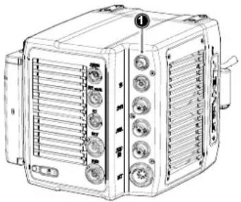
natural_image
Line drawing of an electronic device with ventilation grilles and buttons (no text or symbols)Radio Power
▶ Select MENU > Electronic Control System (ECS) > Radio > Power
and set white radio power on or off. Per factory default, radio power is disabled.
WRS
Active white radio is indicated through the WRS (Wireless Remote System) icon displayed on the HOME screen as well as in the status info of the viewfinder and the SDI outputs.
Additional radio information is displayed in two status entries in the white radio submenu:
▶ MENU > Electronic Control System (ECS) > Radio > Status shows the current status of the white radio module:
• Off (white radio disabled)
- Init (white radio initializing)
• Ready (white radio initialized and ready to be used)
- Blocked (selected white radio channel is already used by another camera on set)
▶ MENU > Electronic Control System (ECS) > Radio > Connected Devices displays the amount of hand units connected to the camera. Up to three hand units can connect to one camera in parallel.
White Radio Channel
The white radio module offers 14 channels to choose from.
▶ Select MENU > Electronic Control System (ECS) > Radio > Channel and set the white radio channel:
| Channel Frequency | ZigBee | IEEE802.15.4 Channel |
| 0 | 2.410 GHz | 12 |
| 1 | 2.415 GHz | 13 |
| 2 | 2.430 GHz | 16 |
| 3 | 2.435 GHz | 17 |
| 4 | 2.450 GHz | 20 |
| 5 | 2.455 GHz | 21 |
| 6 | 2.470 GHz | 24 |
| Channel Frequency ZigBee | IEEE802.15.4 Channel | |
| 7 | 2.475 GHz | 25 |
| 8 | 2.420 GHz | 14 |
| 9 | 2.425 GHz | 15 |
| 10 | 2.440 GHz | 18 |
| 11 | 2.445 GHz | 19 |
| 12 | 2.460 GHz | 22 |
| 13 | 2.465 GHz | 23 |
Note: Make sure to set the white radio channel accordingly on the hand unit.
Note: Make sure that each camera on set uses its own white radio channel.
Note: It is not supported that one hand unit connects to two cameras in parallel.
Note: When using white radio and WiFi simultaneously it is important to configure the used channels to avoid interference and guarantee optimal performance. See the channel configuration table in the WiFi chapter "WiFi Host Channel" for more information.
Wireless Region Setting
The wireless region setting specifies the region the white radio can be used in compliance with local regulations.
- Select MENU > Electronic Control System (ECS) > Radio > Wireless Region Setting.
The following options are available:
| Australia | India | South Africa |
| Canada | Israel | South Korea |
| China | Japan | Taiwan |
| Egypt | New Zealand | Thailand |
| Europe | Philippines | UAE |
| Hong Kong | Singapore | USA |
| World |
- Set the region the white radio is used in.
ADVICE
Please ensure that the region is configured correctly, as it may be illegal to use white radio in a region other than specified in the setting. All settings are compliant to FCC and IC regulations.
Connect a Hand Unit to the Camera
▶ Make sure camera and hand unit are set to use the same white radio channel and wireless region.
The hand unit connects automatically to the camera.
25.2 Lens Motors
The ALEXA Mini LF supports the use of cforce mini and cforce plus lens motors. Lens motors are connected to the LBUS connector of the lens mount and can be daisy chained. The motors can be hot plugged, no need to switch off the camera.
When connecting a cforce plus motor to the camera please make sure that the LBUS connector(s) on both motor and lens mount are equipped with a silver washer placed below the red nut (2) of the connector.
If the LBUS connectors on either cforce plus motor or lens mount (or both) miss the silver washer (1), the cforce plus motor needs to be supplied with external power (e.g. D-Tap from a battery adapter plate) in order to ensure proper performance.
Note: cforce mini motors are not affected and can always be powered through the lens mount.
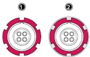
natural_image
Two identical circular mechanical components with red and pink markings, no text or symbols visible.Motor Calibration
After connecting a lens motor to the camera it must be calibrated.
CAL
The camera indicates the calibration request by displaying the CAL icon on the home screen as well as in the status info of the viewfinder and the SDI outputs.
▶ Select MENU > Electronic Control System (ECS) > Calibrate All Motors to start calibration of all connected lens motors.
Additionally, motor calibration can be triggered through the hand unit or the motor itself.
ADVICE
Do not trigger a calibration unless all connected motors are attached to the lens.
Lens Motor Configuration
- Select MENU > Electronic Control System (ECS) > LBUS Lens Motor Configuration.
The following options are available:
Focus/Iris/ Zoom Set the torque of a lens motor, available values in the range of 1 (lowest) Motor Torque to 4 (highest).
Focus/Iris/Zoom Available values are Left and Right. Set direction according to motor position when standing behind the camera. Motor Direction
Focus/Iris/Zoom Selects the number of teeth of the motor. Available values are Auto, 40t, Motor Teeth Count 50t, and 60t.
The motor teeth count setting is only active when a LDA lens table is active and is used to assure correct lens table mappings when using a different motor gear than the one the lens table was initially created with.
You may have to change the direction of the Focus, Iris, and Zoom axis motor depending on the mounting position of the motor (left/right side or top/bottom).
25.3 Lens Data
Lens data can be provided in two different ways, depending on the type of lens:
- LDS Lenses
These lenses contain an integrated electronic interface that sends information about focus, iris and zoom directly to the camera.
- Non-LDS Lenses
These lenses do not have an LDS interface, hence information about focus, iris and zoom need to be gathered from lens motors and translated into sensible values with the help of lens tables. These lens tables are stored in the camera internal Lens Data Archive (LDA).
Lens Data Archive (LDA)
The LDA contains lens tables which offer lens data functionality with non-LDS lenses in connection with lens motors. It is possible to add or delete lens tables from the lens data archive. You can transmit LDA files that are stored on the SD card of the WCU-4 wirelessly to the camera. There is no need to copy the files from the WCU-4 SD card to USB and then to the camera.
When a non-LDS lens is connected, the user can achieve LDS functionality by using the Lens Data Archive. In the LDS screen, a button labeled LDA appears when a non-LDS lens is connected. The LDA screen consists of a user list and a main archive list. The user list should only contain the lenses currently used to achieve quick access to the desired lens tables. The main archive contains a set of lens tables for ARRI/Zeiss High Speeds (also known as Super Speeds), Master Primes and Ultra Primes and can be extended with additional lens tables for any PL-Mount lens.
For information on how to generate a lens table please see the Wireless Compact Unit WCU-4 user manual.
Note: It is possible to load a lens table even when an LDS lens is attached. The LDA values calculated from motor positions and lens tables take precedence over the values communicated by the lens itself. This can be necessary, if the lens data from the lens is faulty or imprecise.
ADVICE
Please note that as soon as a LDA table is activated, the LDS contacts of the lens mount are switched off. There is no need to switch the mount off manually when using LDA.
25.3.1 Adding Lens Tables (LDA)
- Select MENU > Electronic Control System (ECS) > Lens Data > Lens Tables Installed > ADD.
- Press IMPORT to import lens tables from a USB medium or DEFAULTS to select a lens table from the internal lens tables default list.
- Select the desired lens table from the list and press IMPORT.
The lens table is imported to the cameras Lens Tables Installed list. - To use the lens table, select the lens table from the Lens Tables Installed list and press SET.
Some lens tables contain different scale classes for the same model. The scale class of an individual lens is engraved on the lens barrel. If required: select the corresponding scale class from the list.
Lens Tables Favorites List
Frequently used lens tables can be added to a favorites list. The list shows all lenses that have been added before, including the selected scale class.
Add Lens Tables to the Favorites List
- Select MENU > Electronic Control System (ECS) > Lens Data > Lens Tables Installed and select and set a lens table for use.
- Select MENU > Electronic Control System (ECS) > Lens Table > Add to Favorites to add the lens table to the favorites list.
Select a Lens Table from the Favorites List
-
Select MENU > Electronic Control System (ECS) > Lens Data > Lens Table Favorites.
A list with favorite lens tables is displayed. -
Select and set a lens table from the list.
26 Remote Control
26.1 Wireless Control Unit WCU-4
The WCU-4 is an all-inclusive and yet affordable hand unit offering up to 3-axis lens control. It includes a newly designed, super-smooth focus knob with adjustable friction and backlit, optionally pre-marked focus rings that are well readable in the dark without distracting performers. The whole unit is completely splash proof for ARRI-typical reliability. The slider has its scale on the 3" display, providing clearly readable T-stop numbers and optional on-screen markings. If preferred, the slider can be also set to show zoom scales. With the additional ALEXA Remote license, the WCU-4 shows extended camera status information and allows changing camera parameters from the remote unit.
26.2 Web Remote
ALEXA Mini LF has a web remote function for full remote control of the camera with a web browser. The web remote requires a connection to the camera via WiFi or Ethernet (with ALEXA Ethernet/RJ-45 Cable KC-153-S, K2.72021.0).
WiFi is enabled per factory default, If WiFi is inactive, enable WiFi via the MVF-2 in MENU > System > Network / WiFi > WiFi Power. Without the MVF-2 connected enable WiFi by pressing Function button FN and camera button 6.
The web remote is divided into the following five sections:
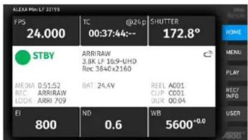
HOME
Shows the same HOME screen as the MVF-2. Click/tap the screen button tabs to enter a screen / trigger a function.
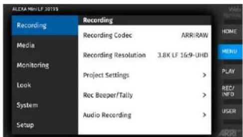
MENU
Select MENU to access the camera menu.
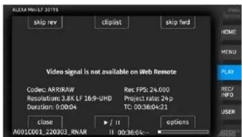
PLAY
Starts playback from the recording medium. Provides the same controls as the MVF-2, but does not show a video signal.
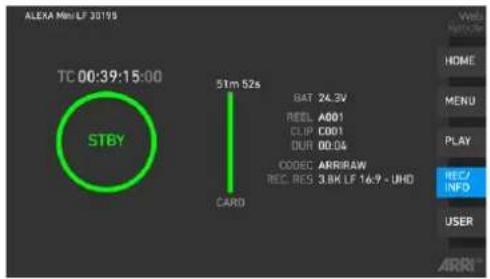
REC / INFO
Contains information on the main recording parameters, plus a REC button. Click the button to start/stop recording.
Note: Recording status and timecode may respond slightly delayed depending on the network's speed.
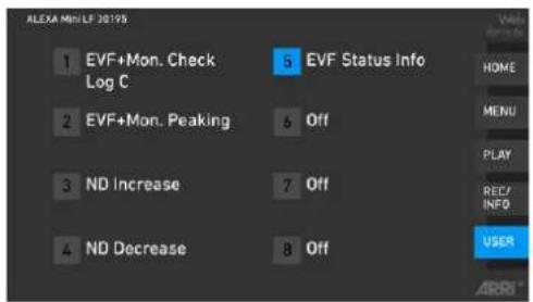
USER
Shows configuration of the camera user buttons and allows you to trigger them. Press the number icons to trigger the user buttons.
Access to Web Remote
▶ Open a web browser and enter the URL: http://mini-LF-xxxxx.local (replace xxxxx with your camera's 5-digit serial number).
To use the web remote function via this URL, the device must support zero-configuration networking (zeroconf), e.g. through Apple Bonjour. Without zeroconf, the web remote can be reached via the network's IP address (WiFi or LAN IP). The WiFi IP is fixed to 192.168.153.1. The LAN IP can be either assigned from a DHCP server or configured manually, and can be checked with an MVF-2 in MENU > Info > Network Info.
ADVICE
Frequent reloading of the web remote camera interface connected with WiFi indicates a limited WiFi range. Please place the device closer to the camera or connect via Ethernet. You may also consider to use the WiFi client mode which allows connecting the camera to a WiFi network.
26.3 Camera Access Protocol (CAP)
The Camera Access Protocol (CAP) is an IP based API used to control and monitor ARRI cameras via a network connection. The protocol incorporates functions to perform color grading, query and set values like exposure index or sensor frame rate, start and stop recording and many more. It is currently available for ALEXA LF, ALEXA Mini LF, ALEXA 65, ALEXA SXT, ALEXA Mini and AMIRA cameras.
Information on the Camera Access Protocol is available through the ARRI partner program free of charge. For more details please see our ARRI Partner Program and the Camera Access Protocol Feature List in the White Papers section on the ARRI website.
Activation of CAP Server
▶ Select MENU > System > Camera Access Protocol (CAP)
to switch remote access to the camera via the Camera Access Protocol on or off.
CAP Server Password
- Select MENU > System > Camera Access Protocol (CAP) > Cap Server Password.
- Use the on-screen keyboard to enter a password used for Camera Access Protocol connections.
CAP Client List
The CAP client list shows the name of the currently connected client. The list shows 'NONE' if no client is connected, and 'NO NAME' if the connected client has not transmitted its name.
▶ Select MENU > System > Camera Access Protocol (CAP) > CAP Client List to display the list.
27 Transvideo Starlite HD5-ARRI Monitor
The Transvideo Starlite HD5-ARRI monitor (K2.0006960) is a 5" 3G-SDI OLED monitor with an integrated H.264 recorder, a touchscreen and a special ARRI bus interface to communicate with the camera. It allows basic operation of the camera. All overlays required for touch operation are generated by the camera and transferred to the Starlite monitor via HD-SDI. For this reason, monitors daisy-chained to the Starlite will show the overlays as well.
Connection to Camera
- Connect the monitor to an SDI output of the camera.
Make sure the SDI image of the output is configured to Processed, not Clean. For more information, see SDI Image.
- Connect the power cable (Lemo 5-pin to Lemo 6-pin):
Connect the Lemo 5-pin plug to the POWER connector of the monitor.
Connect the Lemo 6-pin plug to the EXT connector of the camera.
Main Menu
▶ Activate the menu by pressing the blue "A" touch icon on the monitor.
The main screen opens up:
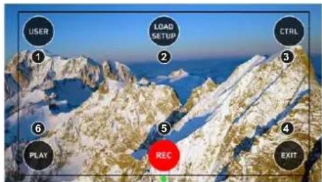
▶ Press USER (1) to access the user button menu.
▶ Press LOAD SETUP (2) to load a user setup from the list of installed user setups on the camera.
▶ Press CTRL (3) to activate the overlay menu.
▶ Press PLAY (6) to start playback.
▶ Press REC (5) to start or stop recording.
▶ Press EXIT (4) to exit the ARRI menu and to return to the standard Starlite mode.
Note: All overlays disappear after a few seconds of inactivity.
User Button Menu
In the user button menu, the same functions are available as with the camera user buttons (1) to (3).
-
Activate the menu by pressing the blue "A" touch icon on the monitor.
-
Press USER to access the user button menu.
The user screen is displayed:
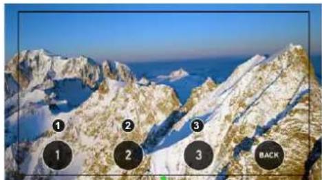
natural_image
Aerial view of snow-covered mountain peaks with numbered annotations (1, 2, 3) and a 'BACK' label, set against a blue sky and sea.▶ Press the buttons to toggle the assigned user button function.
▶ A gray button indicates an active function.
▶ Return to the main menu by pressing the BACK icon.
User Setup Menu
In the load user setup menu, you can load user setup files that have been stored on the camera.
- Activate the menu by pressing the blue "A" touch icon on the monitor.
- Press LOAD SETUP to load a user setup from the list of installed user setups on the camera.
The user setup screen is displayed:
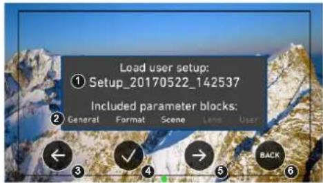
▶ Select the user setup file to be loaded (1) with the left (3) and right (5) arrow buttons.
▶ Confirm the selection of the user setup file by pressing the checkmark (4).
▶ Cancel user setup loading and return to the main menu by pressing BACK (6).
Control Menu
In the control menu, the main camera parameters can be edited similar to the Overlay Menu.
- Activate the menu by pressing the blue "A" touch icon on the monitor.
- Press CTRL to activate the overlay menu.
The control screen is displayed:
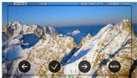
natural_image
Snow-covered mountain range with blue sea and clear sky, overlaid with directional arrows (left, down, right) and a 'BACK' button (no text or symbols on the mountains)▶ Select a parameter by pressing the touch icon (1) or (3) to move the selection rectangle left or right.
▶ Select the parameter by pressing the touch icon (2).
▶ Edit the parameter by pressing the touch icons (1) or (3).
▶ End editing by pressing the touch icon (2).
▶ Exit the control menu by pressing the BACK (4) icon.
Playback Menu
- Activate the menu by pressing the blue "A" touch icon on the monitor.
- Press PLAY to start playback.
The playback screen is displayed:
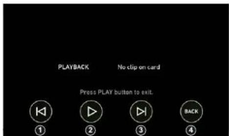
▶ Play or pause a clip by pressing the PLAY touch icon (2).
▶ Skip to previous or to next clip by pressing the Skip previous (1) or Skip next (3) touch icons.
▶ While playback is running, press Fast backward (1) or Fast forward (3) to decrease or increase playback speed.
▶ Exit playback and return to the main menu by pressing the BACK touch icon (3).
28 Appendix
28.1 Companion Tools
ARRI maintains various tools to support your work with the ALEXA Mini LF on- and off-set. In the following overview, some of the tools are highlighted “online only” (green border) the others are available as download for Linux, macOS or Windows.
ARRI Reference Tool
The ARRI Reference Tool (ART) combines the functionality of the ARRIRAW Converter, ARRI Color Tool, and ARRI Meta Extract. It supports all ALEXA 35 recording formats and allows the creation of look files, conversion to SDR and HDR color spaces with looks applied, and export to Apple ProRes, OpenEXR and TIFF files.
The ARRI Reference Tool allows you to process ARRIRAW from ALEXA Mini LF with either the original ARRI color science (LogC3/AWG3) or with the new REVEAL Color Science (LogC4/AWG4), which provides greatly improved image quality as well as compatibility with footage shot on ALEXA 35.
ARRI Reference Tool
Camera Simulators
The camera simulator is an interactive learning tool to familiarize yourself with the menu navigation of ARRI digital cameras. The main user interface on the viewfinder shows a simulation of the real camera. If you choose „Explorer“ from the top-bar you can explore all bits and pieces around the camera, its connectors as well as the viewfinder. Get started now and learn first hand the simple, straightforward menu system that only the ARRI digital cameras offer.
▶ Camera Simulators
Formats and Data Rate Calculator
The ARRI Formats and Data Rate Calculator (FDRC) is an online tool that calculates the record duration and data rates for different camera settings (combinations of camera model, codec, resolution, project rate, sensor speed, recording media, audio on/off). It also gives deeper insight into available recording formats and camera modes. The section "Format Preview" lists the sensor and recording resolution for each recording format as well as a graphical preview for both sensor and recorded clip.
▶ Formats & Data Rate Calculator
Frame Line & Lens Illumination Tool
The Lens Illumination Tool is an interactive visual guide that shows how different lenses illuminate different sensor modes and target aspect ratios of ARRI ALEXA, ALEXA Mini, ALEXA Mini LF and AMIRA cameras. The LIT is meant as a first step, and as a guide only - we strongly recommend that you shoot your own tests to determine the exact behavior of the lenses you plan to use. Each lens type is designed to cover a certain image circle, within which the manufacturer upholds image quality criteria, including illumination. Lenses still show an image outside of this image circle, but of an undefined image quality. Farther out from the image circle there is a point at which there is no more light, defining the 'illumination circle'. The size of the illumination circle changes based on lens design, focal length, focus setting and iris setting, which is why we have provided tools for playing around with all those parameters. All lenses are brighter, and have a better image quality in the center than in the corners, though light distribution differs vastly between lenses. This guide allows you to take a look at how much illumination there is within a given sensor mode and target aspect ratio. The guide only shows illumination and not any other image quality parameter. It was created by shooting a gray chart with each lens as a rough guide; please note that based on image content your results may vary. For each lens type and focal length, the chart was created by using one particular physical lens (not design data), and we display the serial number of that lens. Based on the manufacturing tolerances and service history of the lenses out there, your results may also vary. The tool accommodates ARRI Signature Primes, the ARRI Ultra Wide Zoom, all ARRI Master Primes (except the 14mm Master
Prime), the ARRI Master Macro, all ARRI Ultra Primes, the ARRI Alura Studio and Lightweight Zooms, and the Cooke Mini S4 18, 25, 32 and 40mm. It's also now possible to upload frame lines (created by you, or other users, with the ARRI Frameline Composer) into the LIT. This enables direct comparisons between different lenses within the particular frame lines.
▶ Frame Line & Lens Illumination Tool
LUT Generator
Generally speaking LUTs (Look Up Tables) are used to manipulate image data. The LUT transforms a digital signal to adjust the sensitivity, gamma and provide a color correct monitoring input. Nowadays on-set color correction is not a novelty anymore, nevertheless Look Up Tables are still needed to convert ARRI's Log C to a viewable format (e.g. REC 2020 or REC 709) or an otherwise needed format (conversion to linear space for VFX). Our LUT Generator can create the LUT you need.
▶ LUT Generator
28.2 Connector Pin-Outs
Note: All pin-outs for camera interfaces appear as seen by the user.
1 MX-1P CTS (white-orange)
2 MX-1N DTR (orange)
3 MX-2P GND (white-green)
4 MX-2N DCD (green)
5 MX-3P TXD (blue)
6 MX-3N RXD (white-blue)
7 MX-4P DSR (white-brown)
8 MX-4N RTS (brown)
9 GND
10 Proprietary - do not use
1 GND
2 Can L
3 VBat
4 Can H
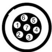
1 Can1 H
2 Can1 L
3 Can2 H
4 Can2 L
5 24 V Aux
6 GND
7 R/S
Ethernet (Computer Side) Headphones Out (on MVF-2)
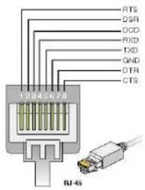
RTS brown
DSR white-brown
DCD green
RXD white-blue
TXD blue
GND white-green
DTR orange
CTS white-orange
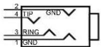
1 GND
2 GND
3 R Out
4 L Out
Audio Cable K2.0023988
ARRI offers an ALEXA Mini LF / ALEXA 35 audio cable with a matching connector to create audio adapters. The following table shows the wire assignments of this cable.
Function Wire
| GND | black |
| CH 1 (+) | blue |
| CH 1 (-) | brown |
| CH 2 (+) | yellow |
| CH 2 (-) | green |
| 12 V | red |
28.3 Technical Data
Sensor Type Large Format ARRI ALEV III (A2X) CMOS sensor with Bayer pattern color filter array
Sensor Size 36.70 x 25.54 mm / 1.444 x 1.005"
∅ 44.71 mm / 1.760"
Photosite Pitch 8.25 μm
Sensor Frame Rates 0.75 - 100 fps
| Sensor Active Image Area (photosites) | 4.5K LF 3:2 Open Gate - 4.5K | 4448 x 3096 |
| 4.5K LF 2.39:1 - 4.5K | 4448 x 1856 | |
| 4.3K LF 16:9 - UHD | 4320 x 2430 | |
| 4.3K LF 16:9 - HD | 4320 x 2430 | |
| 3.8K LF 16:9 - UHD | 3840 x 2160 | |
| 3.8K LF 16:9 - 2K | 3840 x 2160 | |
| 3.8K LF 16:9 - HD | 3840 x 2160 | |
| 2.8K LF 1:1 - 2.8K | 2880 x 2880 | |
| 3.4K S35 3:2 - 3.4K | 3424 x 2202 | |
| 3.2K S35 16:9 - 3.2K | 3200 x 1800 | |
| 2.8K S35 4:3 - 2.8K | 2880 x 2160 | |
| 2.8K S35 16:9 - HD | 2880 x 1620 | |
| Sensor Active Image Area (dimensions) | 4.5K LF 3:2 Open Gate - 4.5K | 36.70 x 25.54 mm / 1.445 x 1.006" |
| 4.5K LF 2.39:1 - 4.5K | 36.70 x 15.31 mm / 1.445 x 0.603" | |
| 4.3K LF 16:9 - UHD | 35.64 x 20.05 mm / 1.403 x 0.789" | |
| 4.3K LF 16:9 - HD | 35.64 x 20.05 mm / 1.403 x 0.789" | |
| 3.8K LF 16:9 - UHD | 31.68 x 17.82 mm / 1.247 x 0.702" | |
| 3.8K LF 16:9 - 2K | 31.68 x 17.82 mm / 1.247 x 0.702" | |
| 3.8K LF 16:9 - HD | 31.68 x 17.82 mm / 1.247 x 0.702" | |
| 2.8K LF 1:1 - 2.8K | 23.76 x 23.76 mm / 0.935 x 0.935" | |
| 3.4K S35 3:2 - 3.4K | 28.25 x 18.16 mm / 1.112 x 0.714" | |
| 3.2K S35 16:9 - 3.2K | 26.40 x 14.85 mm / 1.039 x 0.585" | |
| 2.8K S35 4:3 - 2.8K | 23.76 x 17.81 mm / 0.935 x 0.701" | |
| 2.8K S35 16:9 - HD | 23.76 x 13.36 mm / 0.935 x 0.526" | |
| Recording File Container Size (pixel) | 4.5K LF 3:2 Open Gate - 4.5K (Apple ProRes) | 4480 x 3096 |
| 4.5K LF 3:2 Open Gate - 4.5K (ARRIRAW) | 4448 x 3096 | |
| 4.5K LF 2.39:1 - 4.5K (Apple ProRes) | 4480 x 1856 | |
| 4.5K LF 2.39:1 - 4.5K (ARRIRAW) | 4448 x 1856 | |
| 4.3K LF 16:9 - UHD (Apple ProRes) | 3840 x 2160 | |
| 4.3K LF 16:9 - HD (Apple ProRes) | 1920 x 1080 | |
| 3.8K LF 16:9 - UHD (Apple ProRes) | 3840 x 2160 | |
| 3.8K LF 16:9 - 2K (Apple ProRes) | 2048 x 1152 | |
| 3.8K LF 16:9 - HD (Apple ProRes) | 1920 x 1080 | |
| 3.8K LF 16:9 - UHD (ARRIRAW) | 3840 x 2160 | |
| 2.8K LF 1:1 2.8K (ARRIRAW) | 2880 x 2880 | |
| 2.8K LF 1:1 2.8K (Apple ProRes) | 3072 x 3024 | |
| 3.4K S35 3:2 - 3.4K (ARRIRAW) | 3424 x 2202 | |
| 2.8K S35 4:3 - 2.8K (Apple ProRes) | 2880 x 2160 | |
| 3.2K S35 16:9 - 3.2K (Apple ProRes) | 3200 x 1800 | |
| 2.8K S35 16:9 - HD (Apple ProRes) | 1920 x 1080 | |
| Exposure Latitude | 14+ stops over the entire sensitivity range from EI 160 to EI 3200 as measured with the ARRI Dynamic Range Test Chart (DRTC-1) | |
Shutter Electronic shutter, 5.0°-356° or 1s - 1/8000s
Recording Formats MXF/ARRIRAW
MXF/Apple ProRes 4444 XQ MXF/Apple ProRes 4444 MXF/Apple ProRes 422 (HQ)
Recording Media Codex Compact Drive™
Recording Frame Rates
| 4.5K LF 3:2 Open Gate - 4.5K | 0.75 - 40 fps |
| 4.5K LF 2.39:1 - 4.5K | 0.75 - 60 fps |
| 4.3K LF 16:9 - UHD | 0.75 - 40 fps |
| 4.3K LF 16:9 - HD | 0.75 - 75 fps |
| 3.8K LF 16:9 - UHD | 0.75 - 60 fps |
| 3.8K LF 16:9 - 2K | 0.75 - 90 fps |
| 3.8K LF 16:9 - HD | 0.75 - 90 fps |
| 2.8K LF 1:1 - 2.8K | 0.75 - 60 fps |
| 3.4K S35 3:2 - 3.4K | 0.75 - 60 fps |
| 3.2K S35 16:9 - 3.2K | 0.75 - 75 fps |
| 2.8K S35 4:3 - 2.8K | 0.75 - 75 fps |
| 2.8K S35 16:9 - HD | 0.75 - 100 fps |
Recording Modes Standard real-time recording
Viewfinder Type Multi Viewfinder MVF-2 with 4,0" flip-out monitor and CoaXPress interface
Viewfinder Technology OLED viewfinder display LCD flip-out monitor
Viewfinder Resolution (pixel) 1920 x 1080
Viewfinder Diopter Adjustable from -5 to +5 diopters
Color Output Rec 709
Rec 2020
Log C
Custom Look (ARRI Look File ALF-2)
Look Control Import of custom 3D LUT
ASC CDL parameters (slope, offset, power, saturation)
White Balance Manual and auto white balance, adjustable from 2000K to 11000K in 10K steps Color correction adjustable range from -16 to +16 CC 1 CC corresponds to 035 Kodak CC values or 1/8 Rosco values
Filters Built-in motorized FSND filters 0.6, 1.2, 1.8
Fixed optical low pass, UV, IR filter
Image Outputs 1x proprietary signal output for MVF-2 viewfinder on VF CoaXPress connector
2x SDI outputs on BNC connectors, both outputs carry uncompressed video with embedded audio and metadata.
SDI 1: HD only, Processed or Clean, with or without a look file applied
1.5G 422 HD (SMPTE ST292-1, up to 30 fps, p or psf)
3G 422 HD (SMPTE ST425-1, up to 60 fps, p)
3G 444 HD (SMPTE ST425-3, up to 30 fps, p)
SDI 2: HD or UHD, Clean only, with or without a look file applied, or SDI 1 clone
1.5G 422 HD (SMPTE ST292-1, up to 30 fps, p or psf)
3G 422 HD (SMPTE ST425-1, up to 60 fps, p)
3G 444 HD (SMPTE ST425-3, up to 30 fps, p)
6G 422 UHD (SMPTE ST2081-10, up to 30 fps, p)
"Clean" is an image without surround view or overlays (status, false color, zebra, frame-lines, etc.), "Processed" is an image supporting surround view and overlays.
Lens Squeeze Factors 1.00, 1.25, 1.30, 1.50, 1.65, 1.80, 2.00
Exposure and Focus Tools False Color, Zebra, Zoom, Aperture and Color Peaking
Audio Input 1x LEMO 6pin balanced stereo line in (Line input max. level +24dBu correlating to 0dBFS)
Built-in microphones for scratch audio
Audio Output SDI (embedded)
3.5 mm Headphones out on MVF-2
Audio Recording 4 channel linear PCM (24 bit, 48 kHz)
Remote Control Options
MVF-2 viewfinder can act as wired remote control with 10m/33ft cable, web-based remote control from smart phones, tablets and laptops via WiFi & Ethernet, Camera Access Protocol (CAP) via Ethernet & WiFi, GPIO interface for integration with custom control interfaces, WCU-4 hand-unit with control over lens motors and operational parameters via built-in white radio, SXU-1 hand-unit with control over one lens axis, OCU-1 and Master Grip control of lens and user buttons
Interfaces 1x LEMO 5pin LTC Timecode In/Out
1x LEMO 10pin Ethernet for remote control and service
1x BNC SYNC IN
1x LEMO 7pin EXT multi purpose accessory interface w. RS pin and 24V power output
1x LEMO 4pin LBUS (on lens mount) for lens motors, daisy chainable
1x USB 2.0 in media bay (for user setups, look files etc)
Wireless Interfaces
Built-in WiFi module (IEEE 802.11b/g) Built-in White Radio for ARRI lens and camera remote control
Lens Mounts ARRI LPL Mount (LBUS)
ARRI PL to LPL adapter
ARRI EF Mount (LBUS)
Leitz Cine Wetzlar M Mount
Flange Focal Depth LPL mount: 44 mm
With PL to LPL adapter: 52 mm
Power Input 1x LEMO 8pin (11.0 - 34.0 V DC)
Power Consumption Around 69 W when recording ARRIRAW LF 16:9 UHD at 24 fps with MVF-2 attached
Power Outputs 1x Fischer 3pin 24V RS (3.0 A)
1x LEMO 2pin 12V (1.0 A)
1x LEMO 7pin EXT 24V (1.0 A)
1x LEMO 4pin LBUS 24V (2.0 A, on lens mount)
1x LEMO 6pin AUDIO 12V
1x LEMO 10pin ETH 24 V (0.5 A)
Measurements (HxWxL)
140 x 143 x 188 mm / 5.5 x 5.6 x 7.4" (camera body with LPL lens mount)
Weight
\~ 2.7 kg / \~ 5.7 lbs (camera body with LPL lens mount)
Operating Temperature
-20°C to +45°C / -4°F to +113°F @ 95% relative humidity max, non condensing, splash and dust proof through sealed electronics
Storage Temperature
-30°C to +70°C / -22°F to +158°F
Sound Level
< 20 dB(A) at 24fps
28.4 Declarations of Conformity
Approval Information
The products offered by ARRI are approved for use in a number of countries. Product-specific information on approval can be found in the respective operating instruction manuals. Import and use in countries other than those mentioned in the respective operating instructions may be subject to legal, regulatory, or official requirements and regulations. Before the products are imported into these countries or used in these countries, compliance with the existing legal, regulatory, and administrative requirements and regulations must be ensured. It is the importer's or the user's responsibility, prior to importation or use, to inform themselves of the applicable legal, regulatory, and administrative requirements and regulations and to ensure compliance with these requirements and regulations, including applying for and obtaining any necessary approvals or registrations.
As far as reasonable and legally possible, ARRI will support requests in relation to such applications by providing technical documents or declarations. As an importer or user, you confirm that you are familiar with and comply with the legal, regulatory, and administrative requirements and regulations that apply in the countries to which you ship or use the products. You further confirm that you will arrange for any necessary registrations, enrollments, or authorizations that are required in such countries.
You release ARRI from all obligations resulting from any legislative, regulatory, or administrative requirements regarding import or use of the products, except in countries where ARRI has obtained a registration or certification. You agree to indemnify, defend, and hold ARRI harmless from any and all claims, damages, losses, liabilities, costs, and expenses (including reasonable fees of attorneys and other professionals) that may arise out of a demand on ARRI in connection with your obligations mentioned above.
EU Declaration of Conformity
Brand Name: ARRI
Product Description: Digital Camera System
• ARRI ALEXA MINI LF + Multi Viewfinder MVF-2
+ Europe Setting for Software 6.0 or later, Primes following Appendix I, Antenna following Appendix II
The designated products conform to the specifications of the following European directives:
1 Directive 2014/53/EU of the European Parliament and the Council of 16 April 2014 on the harmonization of the laws of the Member States relating to the making available on the market of radio equipment - OJ L 153, 22 May 2014, p. 62–106.
2 Directive 2011/65/EU of the European Parliament and the Council of 8 June 2011 on the restriction of the use of certain hazardous substances in electrical and electronic equipment - OJ L 174, 1 July 2011, p. 88–110.
The compliance with the requirements of the European Directives was proved by the application of the following standards:
Essential Requirements regarding No 1:
Following Art. 3.1 a,
2014/35/EU:
EN 62368-1:2014 + AC:2015-05 + AC:2015-11;
EN 62311:2008
Following Art. 3.1 b,
2014/30/EU:
EN 301 489-1 V2.1.1
Essential Requirements regarding No 2:
EN 50581:2012
To evaluate the respective information, we used:
http://ec.europa.eu/growth/single-market/european-standards/harmonised-standards/index_en.htm
Year of affixed CE-marking: 2019
APPENDIX I - List of Primes
| Item Model Name |
| 1 ARRI Signature Primes with Lens Data System 2 with focal length 18-280 mm |
| 2 PL-to-LPL Adapter + ARRI Lenses with Lens Data System 1 |
APPENDIX II - List of Antennas
| Item Manufacturer Model Name Gain | (dBi) | Radiation Pattern | Type Connector | |||
| For ECS White Radio RF Module EMIP400s: | ||||||
| 1 Nearson S131AM-2450S 2.0 Omni-directional Dipole | Reverse SMA | |||||
| 2 Proant 333 (Ex-it 2400 | Foldable) | 2.0 Omni-directional Dipole Reverse SMA | Reverse SMA | |||
| 3 Radial/Larsen R380.500.125 | 2.0 Omni-directional Dipole Reverse SMA | |||||
| 4 Wanshih WSS002 | 2.0 Omni-directional Dipole Reverse SMA | |||||
| 5 | Taoglas | GW26.0151 | 1.8 | Omni-directional | Monopole | Reverse SMA |
| For WiFi 2.4 GHz RF Module ST60-2230C: | ||||||
| 6 | Radial | R380.500.150 | 0.0 | Omni-directional | Monopole | Reverse SMA |
| 7 LAIRD LSR/001-009 2.0 Omni-directional Dipole Reverse SMA | ||||||
FCC Compliance Statement
Class B Statement: This equipment has been tested and found to comply with the limits for a Class B digital device, pursuant to part 15 of the FCC Rules. These limits are designed to provide reasonable protection against harmful interference in a residential installation. This equipment generates, uses and can radiate radio frequency energy and, if not installed and used in accordance with the instructions, may cause harmful interference to radio communications. However, there is no guarantee that interference will not occur in a particular installation. If this equipment does cause harmful interference to radio or television reception, which can be determined by turning the equipment off and on, the user is encouraged to try to correct the interference by one or more of the following measures:
• Reorient or relocate the receiving antenna.
- Increase the separation between the equipment and receiver.
- Connect the equipment into an outlet on a circuit different from that to which the receiver is connected.
- Consult the dealer or an experienced radio/TV technician for help.
• WIFI: FCC ID: SQG-60SIPT
• ECS transceiver module: FCC ID: Y7N-EMIP400
Industry Canada Compliance Statement
Complies with the Canadian ICES-003 Class B specifications.
This device contains licence-exempt transmitter(s)/receiver(s) that comply with Innovation, Science and Economic Development Canada's licence-exempt RSS(s). Operation is subject to the following two conditions: This device may not cause interference. This device must accept any interference, including interference that may cause undesired operation of the device.
- Dealer's License No: DA103787 Registration valid until 31. August 2024 for ALEXA Mini LF (EMIP400s & LAIRD ST60-2230C)
Complies with
IMDA Standards
DA103787
India WPC Compliance Statement
Registration No.: ETA-SD-20201108443
South Korea
Statement for 2.4 GHz Devices:
"해당무선설비는 운용 중 전파혼신 가능성이 있음" Translation for reference only: This radio device has the possibility of radio interference.
Japan Australia & New Zealand

• ECS Transceiver Module
EMIP400: 020-180030
• WiFi Module: 003-170091

- ALEXA Mini LF
Cambodia Philippines

Type Approval TRC Indentifier 0256-2019-niLF

No. ESD - 1921399C
Egypt South Africa

TAC.24121919782.WIR TA 2019/2202 APPROVED

South Korea

• ALEXA Mini LF: Certification No: R-R-ARg-ALEXA_Mini_LF
• ECS Transceiver Module: Certification No: R-CRM-ARg-EMIP400
• WiFi Module: Certification No: MSIP-CRM-LAI-60-2230C
United Arab Emirates
• Wireless video devices: Dealer No: DA68290/17
(Registration valid until: 28th August, 2022; brand registration: 5 years)
• ALEXA Mini LF: registered No: ER74494/19
Thailand
Supplier Declaration of Conformity - 55/107 No 2932
Peru
28.5 ARRI Service Contacts
Please see the current list of service partners at Service contacts
Arnold & Richter Cine Technik
2 Highbridge, Oxford Road
UB8 1LX Uxbridge
United Kingdom
+44 1895 457 000
Business hours:
Mo. - Thu. 09:00 - 17:30
Fr. 09:00 am - 05:00 pm (GMT)
service@arri-ct.com
ARRI Inc. / West Coast
3700 Vanowen Street
CA 91505 Burbank
USA
+1 818 841 7070
Business hours:
Mo. - Fr. 09:00 am- 05:00 pm (PT)
service@arri.com
ARRI Inc. / East Coast
617 Route 303
NY 10913 Blauvelt
USA
+1 845 353 1400
Business hours:
Mo. - Fr. 08:00 am - 05:30 pm (EST)
service@arri.com
ARRI Canada Limited
1200 Aerowood Drive, Unit 29
ON L4W 2S7 Mississauga
Canada
+1 416 255 3335
Business hours:
Mo. - Fr. 08:30 am - 05:00 pm (EDT)
service@arri.com
ARRI Australia Pty Ltd
Suite 2, 12B Julius Ave
NSW 2113 North Ryde
Australia
+61 2 9855 4305
Business hours:
Mo. - Fr. 08:00 am - 05:00 pm (AEST)
service@arri.com.au
ARRI Asia Pte. Ltd.
164 Kallang Way, #03-01
349248 Singapore
Singapore
+65 6230 9488
Business hours:
Mo. - Fr. 9:00 am - 06:00 pm (CST)
service@arri.asia
ARRI China (Beijing) Co. Ltd.
Chaowai SOHO Tower C, 6/F, 0628/0656
Chaowai Dajie Yi 6
Beijing
China
+86 10 5900 9680
Business hours:
Mo. - Fr. 09:00 am - 06:00 pm (CST)
service@arri.cn
ARRI Hong Kong Limited
41/F One Kowloon, 1 Wang
Yuen Street Kowloon Bay
Hong Kong
China
+852 2537 4266
Business hours:
Mo. - Fr. 09:00 am - 06:00 pm (CST)
service@arri.asia
ARRI Korea Limited
Kolon Digital Tower 1(#1505-06), 25
Seongsuil-ro 4 gil, Seongdong-gu
04781 Seoul
Korea
+82 (0)70 4419 6401
Business hours:
Mo. - Fr. 9:00 am - 06:00 pm (KST)
service@arri.kr
ARRI Japan Kabushiki Kaisha
Service
Haneda Innovation City Zone K210, 1-1-4
Hanedakuko, Ota-Ku
144-0011 Tokyo
Japan
+81 3 6635 3750
Business hours:
Mo. - Fr. 10:00 am - 06:00 pm (JST)
info@arri.jp
ARRI Brasil Ltda
Avenida Ibirapuera 2907 – Cj. 421, Indianópolis
04029-200 São Paulo
Brazil
+55 1150419450
Business hours:
Mo. - Fr. 09:00 am - 05:30 pm (BRT)
arribrasil@arri.com
CINEOM Broadcast DMCC.
Unit No. 2109, Jumeirah Bay Tower X2 Cluster X
Jumeirah Lakes Towers
P.O Box 414659
Dubai, UAE
+971 (0) 45570477
Business hours:
Sa. - Th. 10:00 am- 06:00 pm
arriservice.me@cineom.com
CINEOM Broadcast India Pvt. Ltd.
C-4, Goldline Business Centre
Link Rd. Malad West
400 064 Mumbai
India
+91 (0)22 42 10 9000
Business hours:
Mo. - Sat. 10:00 am - 06:00 pm (IST)
arrisupportindia@cineom.com
LINKA Ithalat Ihracat ve Diş Tic.
Distributor
Halide Edip Adivar Mah. Darülaceze Cad.
28.6 Dimensional Drawings
Dimensional drawings are attached at the end of this document. They are also available for download on the ARRI website.
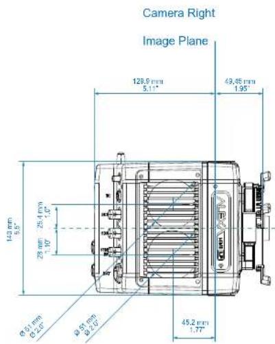
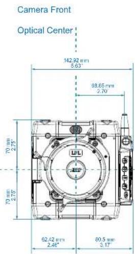
Optical Center
ALEXA Mini LF
| Length | Width | Height | Weight |
Body + LPL mount
MVF-2
188 mm - 7.4" 143 mm - 5.6" 140 mm - 5.5" \~2.6 kg / \~5.7 lbs
800 g
Camera Left
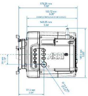
Camera Top
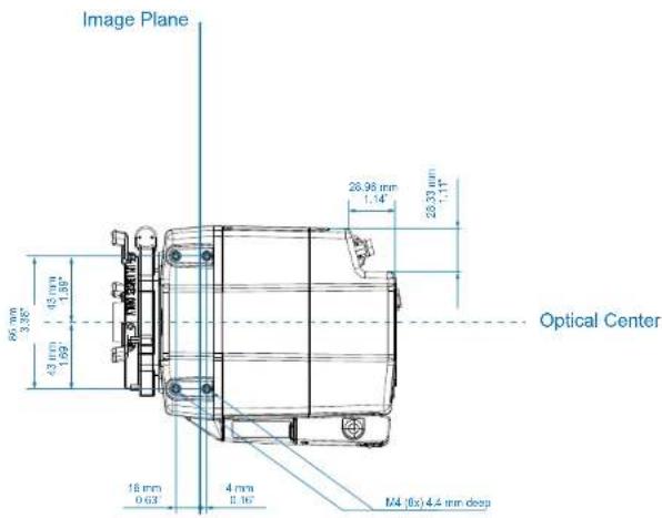
ALEXA Mini LF
Length
Width
Height
Weight
Body + LPL mount
MVF-2
188 mm - 7.4" 143 mm - 5.6" 140 mm - 5.5" \~2.6 kg / \~5.7 lbs
800 g


- Imprint
- For Further Assistance
- Contents
- Transvideo Starlite HD5-ARRI Monitor....134
- Disclaimer
- 危险
- 警告
- 小心
- 注意
- Risk of electric shock or fire!
- Risk of injury and damage!
- 触电或起火的风险!
- Condensation! Risk of electric shock and fire!
- Hot surfaces! Risk of injury and damage!
- Crushing hazard!
- ⚠ 小心
- 凝露有触电和起火的风险!
- 频闪
- 滚动快门
- “黑太阳”
- Stuck Pixels at Long Exposure Times
- 长曝光时间的驻留像素
- Stitching with ALEXA Mini LF
- ALEXA Mini LF 的画面接合
- Audience and Intended Use
- How To Use This Manual
- ADVICE
- Additional Information
- Strengthen Your Knowledge and Get Trained
- Scope of Delivery and Warranty
- Delivery
- Warranty
- Introduction to the ALEXA Mini LF
- Camera Layout
- Camera Rear Connectors
- ETH (10-pin LEMO)
- EXT (7-pin LEMO)
- RS (3-pin Fischer)
- 12V (2-pin LEMO)
- AUDIO (6-pin LEMO)
- White Radio Antenna Connector (Female RP-SMA)
- TC (5-pin LEMO)
- SDI 1 & SDI 2 (BNC)
- SYNC IN (BNC)
- BAT (8-pin LEMO)
- Camera Left and Front Connectors
- LBUS Connector (4-pin LEMO, on LPL Lens Mount)
- VF Viewfinder Connector (CoaXPress)
- WiFi Antenna Connector (RP-SMA)
- Camera Buttons
- Media Bay
- Recording Media Slot
- USB Connector
- Product Identification
- Camera Support
- Required Tools
- CAUTION
- Power Supply
- BAT IN
- Accessory Power
- V
- V
- Power Consumption
- Switching On and Off
- Switching On the Camera
- Switching Off the Camera
- Automatic Boot-up on Power
- Lens Mounts and Lens Handling
- ARRI LPL Mount (LBUS) and PL-to-LPL Adapter
- ARRI LPL Mount (LBUS)
- PL-to-LPL Adapter
- ARRI EF Mount (LBUS)
- EF Iris Control
- Changing a Lens
- ARRI LPL Mount (LBUS), PL-to-LPL Adapter and PL Mount Lenses
- Removing a Lens or the Lens Mount Cap
- Attaching a Lens
- Dust particles may settle on the sensor cover glass during a lens change!
- Damage to Lens mount or camera!
- Lens Support
- Maximum Lens Mounting Depth
- Changing the Lens Mount
- Required Tools and Precautions
- Removing a Lens Mount (here: ARRI LPL Mount (LBUS))
- Installing a Lens Mount (here: ARRI LPL Mount (LBUS))
- WARNING
- High voltage! Risk of electric shock and fire!
- Condensation! Risk of electric shock and damage!
- Lens Data
- ARRI Lens Data System (LDS)
- ARRI Lens Data Archive (LDA)
- Cooke /i
- Lens Data Display in Camera
- Lens Data in Metadata
- MVF-2 Overview
- OLED Display
- Flip-out Monitor
- Diopter Adjustment
- Proximity Sensor
- Built-in Eyepiece Heater
- EXP (Exposure Tool Button)
- ZOOM Button
- PLAY Button
- VF1 and VF2 User Buttons
- User Wheel and SET Button
- LOCK Switch
- REC Button
- Product Label
- Viewfinder Connector
- Headphones Out
- Flip-out Monitor
- JOGWHEEL
- HOME / LIVE Button
- MENU / BACK Button
- Screen Buttons
- MVF-2 Cables
- Viewfinder Cables
- Menu Operation
- HOME Screen
- FPS (Sensor Frame Rate)
- TC (Timecode)
- SHUTTER
- EI (Exposure Index)
- ND Filter
- WB (White Balance)
- Status Section
- STBY
- Camera Status
- Codec & Recording Resolution
- Audio Meters
- Clip Information
- Battery Level
- Media Capacity & Look Settings
- Status Icons
- Using the On-screen Keyboard
- Working with Lists and Importing Files
- Adding Entries to Value based Lists
- Importing Files
- Deleting List Entries
- Maximum Entries per List
- Function Button FN
- Camera Buttons to Access Common Camera Functions
- User Storage Handling
- User Storage Status on HOME screen and in Camera Menu
- Prepare User Storage for Use
- Remove User Storage
- Info Screens
- Version Info
- System Info
- Maximum FPS Info
- Media Info
- USB Info
- Network Info
- Lens Info
- User Button Info
- EXT Sync Info
- Export HW Info File
- Export Logfiles
- Export Update Logfiles
- Alerts Screen
- Main Parameters
- Project Settings
- Project Rate
- Next Reel Count
- Camera Index
- Camera Index Color
- Camera ID Prefix
- Lens Squeeze Factor
- Sensor Frame Rate
- Setting the Sensor Frame Rate
- Shutter
- Changing the Shutter
- Adjusting the Shutter for Filming a Monitor
- Shutter Unit
- Exposure Index
- Setting the Exposure Index
- EF Lens Iris Adjustment
- ND Filter
- Internal FSND Filters
- Selecting the ND Filter
- White Balance
- Preset and Custom White Balance
- Automatic White Balance
- Timecode
- Free Run Timecode, Time of Day
- Rec Run Timecode
- Setting the Timecode Manually
- Timecode Run Mode
- Timecode Mode
- Regen Source
- Timecode Count Mode
- Timecode Offset
- Look Settings
- ARRI Look File 2
- Camera Default Look Files
- Look Description
- Setting the Look
- Playback and ARRI Look File 2 files
- Processing and Color Spaces
- Log C
- Configuration of EVF/Mon. and SDI Processing
- Select
- Select the desired processing for each output.
- Configuration of SDI Color Space
- Recording
- Recording Medium
- Hot Surfaces on Recording Media
- Recording Media Damage due to improper Handling
- Codex Compact Drives
- Inserting the Codex Compact Drive
- Removing the Codex Compact Drive
- Erasing the Recording Medium
- Erase of Recording Media
- Remaining Recording Capacity and Media Information
- Starting Recording via REC button
- Other Ways to Start Recording
- Recording Codec
- MXF (Material eXchange Format)
- MXF/ARRIRAW
- MXF/Apple ProRes
- File Structure
- Selection in Camera Menu
- Recording Resolution
- Recording Codec
- Sensor Mode
- Recording File Container Size
- Audio Recording
- Audio Inputs
- Audio Recording
- Channel 1/2 Control
- Channel 1/2 Gain
- Internal Microphones
- Headphones Volume
- Test Tone
- Rec Beeper and Tally Settings
- File Naming Scheme
- Data Handling
- Playback
- Starting Playback Using the PLAY Button on MVF-2
- Playback Screen & Controls
- Cliplist
- Playback Options
- Monitoring
- Status Information and Status Overlays
- EVF and SDI Status Information
- Top Section
- Bottom Section
- Other
- Configuration of Overlays
- Configuration of Status Info Components
- Flip-out Monitor Status Bar
- Overlay Menu
- Activation and Control Using the Camera Buttons
- Activation and Control Using a User Button
- Surround View
- Surround Mask
- Frame Border
- Magnification
- Setting the Magnification
- Frame Lines
- Setting the Frame Line
- Frame Line Color
- User Rectangles
- Frame Line Outside Shading
- Frame Line Intensity
- Frame Lines Saved in Metadata
- Anamorphic Desqueeze
- Setting the Lens Squeeze Factor
- Activation of Anamorphic Desqueeze for EVF/Monitor and SDI
- Exposure Tools
- Activation of Exposure Tool with MVF-2
- Activation of Exposure Tool with User Buttons
- Activation of Exposure Tool in Camera Menu
- False Color
- False Color Configuration
- False Color Mode
- Monitoring-based
- Log C-based
- Zebra
- Zebra Configuration
- Zebra Setup
- Focus Tools
- Peaking
- Peaking Configuration
- Activation of Peaking
- Zoom
- Zoom on EVF/Monitor
- Zoom on SDI
- SDI Outputs
- SDI Format
- Set the desired SDI format.
- SDI Processing
- SDI Frame Rate
- SDI 3G Level
- SDI Image
- SDI 2 Clone
- Preventing Damage to SDI Outputs
- Problem Description
- EVF/Monitor Settings
- Color Bars
- Synchronization
- EXT Sync
- EXT Sync Mode
- Media Status with EXT Sync
- EXT Sync Info Screen
- Media Erase in EXT Sync
- EXT Sync Clip Naming
- Genlock Synchronization
- Activation of Genlock
- GEN
- Sync Shift
- Timecode Synchronization
- Activation of Timecode Synchronization
- Sensor Settings
- Noise Reduction
- ARRI Noise Reduction ANR-1
- Mirroring the Sensor Image
- User Pixel Masking
- User Pixel Mask Generation
- System Settings
- Language Setting
- System Time and Date
- Button and Display Settings
- Fan Settings
- Battery Warning
- Lens Mount Settings
- Network and WiFi Settings
- WiFi Settings
- WiFi Power
- External Antenna
- WiFi Mode
- WiFi Host Channel
- WiFi Password (Host Mode)
- Connect to a Network (Client Mode)
- Connect to a Network using a QR Code (Client Mode)
- Disconnect from Network (Client Mode)
- WiFi Status Icons on HOME Screen and in Status Info
- LAN Settings
- LAN IP Mode
- LAN Static IP
- LAN Static Subnet
- Reset of Electronic Horizon
- Camera Update
- Update of Camera Software
- Update of Camera Components
- Update of LBUS Devices
- User Setups
- Saving a User Setup
- Loading a User Setup
- Factory Reset
- User Setup Parameter Blocks
- GENERAL
- FORMAT
- SCENE
- LENS
- USER
- User Buttons
- Camera User Buttons
- MVF-2 User Buttons
- Additional User Buttons
- Smart Behavior
- User Button Info Screen
- List of User Button Functions
- Metadata
- Production Metadata in Camera Menu
- Select MENU > Metadata.
- Select the metadata field you want to edit.
- Electronic Control System (ECS)
- White Radio Configuration
- Radio Power
- WRS
- White Radio Channel
- Wireless Region Setting
- Connect a Hand Unit to the Camera
- Lens Motors
- Motor Calibration
- CAL
- Lens Motor Configuration
- Lens Data
- Lens Data Archive (LDA)
- Adding Lens Tables (LDA)
- Lens Tables Favorites List
- Add Lens Tables to the Favorites List
- Select a Lens Table from the Favorites List
- Remote Control
- Wireless Control Unit WCU-4
- Web Remote
- HOME
- MENU
- PLAY
- REC / INFO
- Access to Web Remote
- Camera Access Protocol (CAP)
- Activation of CAP Server
- CAP Server Password
- CAP Client List
- Transvideo Starlite HD5-ARRI Monitor
- Connection to Camera
- Main Menu
- User Button Menu
- User Setup Menu
- Control Menu
- Playback Menu
- Appendix
- Companion Tools
- ARRI Reference Tool
- Camera Simulators
- Formats and Data Rate Calculator
- Frame Line & Lens Illumination Tool
- LUT Generator
- Connector Pin-Outs
- Ethernet (Computer Side) Headphones Out (on MVF-2)
- Audio Cable K2.0023988
- Technical Data
- Declarations of Conformity
- Approval Information
- EU Declaration of Conformity
- • ARRI ALEXA MINI LF + Multi Viewfinder MVF-2
- FCC Compliance Statement
- Industry Canada Compliance Statement
- South Korea
- Cambodia Philippines
- Egypt South Africa
- United Arab Emirates
- Thailand
- Peru
- ARRI Service Contacts
- ARRI Hong Kong Limited
- ARRI Korea Limited
- ARRI Japan Kabushiki Kaisha
- ARRI Brasil Ltda
- CINEOM Broadcast DMCC.
- CINEOM Broadcast India Pvt. Ltd.
- LINKA Ithalat Ihracat ve Diş Tic.
- Dimensional Drawings
Brand : ARRI
Model : Alexa Mini LF
Category : Camera