
Alexa LF - Camera ARRI - Free user manual and instructions
Find the device manual for free Alexa LF ARRI in PDF.


| Product Type | Cinema Camera |
| Brand | ARRI |
| Model | Alexa LF |
| Sensor | Large-Format CMOS, 4.5K (4560 x 2592) |
| Dynamic Range | 14+ stops |
| Lens Mount | ARRI PL Mount (standard), also compatible with LPL |
| Recording Formats | ARRIRAW, ProRes, DNxHD |
| Recording Media | SXR Capture Drives, CFast 2.0 |
| ND Filters | Built-in motorized ND (0.6, 1.2, 2.4) |
| Weight (Body Only) | Approx. 5.6 kg |
| Dimensions | Approx. 300 x 240 x 160 mm |
| Power Input | 24V DC (via V-Mount battery plate or AC adapter) |
| Power Consumption | Approx. 60W |
| Operating Temperature | -20°C to 50°C |
| Shutter | Electronic shutter, 5° to 360° |
| Color Science | ARRI Color Science with LogC gamma |
| Audio Inputs | 2 x XLR, 1 x 5-pin LEMO timecode |
| Connectivity | Ethernet, Wi-Fi (optional), USB, 3G/12G-SDI outputs |
| Monitor | Integrated 2.8" OLED display or external via SDI |
| Lens Control | ARRI Lens Control system compatible |
| Maintenance | Regular sensor cleaning and calibration recommended |
| Safety Standards | CE, FCC |
Frequently Asked Questions - Alexa LF ARRI
User questions about Alexa LF ARRI
0 question about this device. Answer the ones you know or ask your own.
Ask a new question about this device
Download the instructions for your Camera in PDF format for free! Find your manual Alexa LF - ARRI and take your electronic device back in hand. On this page are published all the documents necessary for the use of your device. Alexa LF by ARRI.
USER MANUAL Alexa LF ARRI
Software Update Package 4.0
USER MANUAL
6 November 2018
Copyright
All rights reserved.
This document is provided under a license agreement containing restrictions on use and disclosure and is also protected by copyright law.
Due to continued product development this information may change without notice. The information and intellectual property contained herein is confidential between ARRI and the client and remains the exclusive property of ARRI. If you find any problems in the documentation, please report them to us in writing. ARRI does not warrant that this document is error-free.
Arnold & Richter Cine Technik
Tuerkenstr. 89
D-80799 Munich
Germany
mailto: service@arri.com
http://www.arri.com
Contents
1 Disclaimer....7
2 About This Manual....9
3 Scope.... 10
4 Introduction to the ALEXA LF....11
5 Layout of the ALEXA.... 12
6 Safety Guidelines....14
6.1 Explanation of Warning Signs and Indications....14
6.2 General Safety Guidelines.... 14
6.3 Specific Safety Instructions.... 14
7 General Precautions....16
7.1 Storage and Transport.... 16
7.2 Condensation....16
8 Sensor related image issues....17
9 Power Supply....18
9.1 Power Management.... 18
9.2 BAT Connector.... 18
9.3 Mains Unit NG 12/26 R....19
9.4 Cine-Style Block Batteries....19
9.5 Onboard Batteries.... 20
9.5.1 V-Lock Batteries.... 20
9.5.2 Gold Mount Batteries....20
9.6 Power Outputs....21
10 Camera Support....22
10.1 Minimum Equipment Recommended For Operation.... 22
10.2 Tripod and Remote Heads.... 22
10.3 Electronic Viewfinder.... 22
10.3.1 Viewfinder Cables....24
10.3.2 Viewfinder Mounting Bracket....24
10.4 Center Camera Handle CCH-1.... 26
10.5 Bridge Plates BP-12/BP-13.... 27
10.6 Bridge Plate adapter BPA-1.... 28
10.7 Wedge Adapter WA-1 and Quick-Release Plate QR-HD-1.....28
10.8 Levelling Block LB-1....28
10.9 Shoulder Pad SP-3....29
11 Connectors.... 30
11.1 BAT....31
11.2 RET IN....31
11.3 MON OUT 1/2/3.... 31
11.4 EXT....32
11.5 ETHERNET....32
11.6 EVF 32
11.7 AUDIO IN....32
11.8 RS....32
11.9 12 V....33
11.10 TC....33
11.11 AUDIO OUT....33
11.12 SD Card....33
11.13 LBUS Support....34
12 Recording Module.... 36
13 Lens Mounting.... 40
13.1 LPL mount.... 40
13.2 PL-to-LPL Adapter....41
13.3 Lens Support.... 41
14 In-Camera Filter Module LF IFM.... 43
14.1 Safety instructions for in-camera filtration....44
14.1.1 Maximum lens mounting depth for PL lenses.... 44
14.1.2 Basic precautions.... 45
14.1.3 Required shimming and maximum lens mounting depth.... 45
14.2 LF FSND Filter Set (Full).... 45
14.3 Shimming the lens mount.... 46
14.4 Mounting in-camera filters....52
14.5 Filter cleaning.... 55
15 Camera Controls....57
15.1 Main Controls.... 57
15.1.1 Display....57
15.1.2 Screen Buttons....58
15.1.3 HOME screen....58
15.1.3.1 Lists and User Lists....61
15.1.3.2 FPS....62
15.1.3.3 AUDIO....63
15.1.3.4 SHUTTER....66
15.1.3.5 EI....66
15.1.3.6 COLOR....68
15.1.3.7 WB....71
15.1.4 Function Buttons....73
15.1.4.1 TC....74
15.1.4.2 INFO....75
15.1.4.3 USER....78
15.1.4.4 PLAY....82
15.1.4.5 Wireless Remote System....85
15.1.5 Menu....93
15.1.5.1 Recording....94
15.1.5.2 Monitoring....96
15.1.5.3 Project....104
15.1.5.4 System....106
15.1.5.5 Frame Grabs.... 116
15.1.5.6 User Setups....117
15.2 Operator controls....119
16.1 Setting the region of the wireless video function....125
16.2 Preparation.... 125
16.3 Status LEDs....125
16.4 Pairing camera and receivers.... 125
16.5 Supported resolutions....127
16.6 Sample setups....127
16.7 Software update.... 128
17 Operation of the Camera.... 129
17.1 Internal recording....129
17.1.1 Recording Module.... 129
17.1.2 Internal Recording Formats....129
17.2 Monitoring.... 136
17.2.1 Frame Lines....136
17.2.2 Status Info Overlays.... 137
17.3 Using Timecode....139
17.4 Syncing the Sensors of Two Cameras....140
17.5 Syncing the Settings of Two Cameras.... 142
18 Remote Control Unit RCU-4.... 145
19 Index....146
20 Appendix....149
20.1 Technical data....149
20.2 Connector Pin Outs....152
20.3 False Color Display.... 157
20.4 Warning and Error Messages....158
20.5 Dimensions and Weights....162
20.6 Declarations of Conformity.... 162
1 Disclaimer
Before using the products described in this manual be sure to read and understand all respective instruction.
The ARRI ALEXA is only available to commercial customers. The customer grants by utilization that the ARRI ALEXA or other components of the system are deployed for commercial use. Otherwise the customer has the obligation to contact ARRI preceding the utilization.
While ARRI endeavors to enhance the quality, reliability and safety of their products, customers agree and acknowledge that the possibility of defects thereof cannot be eliminated entirely. To minimize risk of damage to property or injury (including death) to persons arising from defects in the products, customers must incorporate sufficient safety measures in their work with the system and have to heed the stated canonic use.
ARRI or its subsidiaries do not assume any responsibility for incurred losses due to improper handling or configuration of the camera or other system components, due to sensor contamination, occurrence of dead or defective pixels, defective signal connections or incompatibilities with third party recording devices.
ARRI assumes no responsibility for any errors that may appear in this document. The information is subject to change without notice.
For product specification changes since this manual was published, refer to the latest publications of ARRI data sheets or data books, etc., for the most up-to-date specifications. Not all products and/or types are available in every country. Please check with an ARRI sales representative for availability and additional information.
Neither ARRI nor its subsidiaries assume any liability for infringement of patents, copyrights or other intellectual property rights of third parties by or arising from the use of ARRI products or any other liability arising from the use of such products. No license, express, implied or otherwise, is granted under any patents, copyrights or other intellectual property right of ARRI or others.
ARRI or its subsidiaries expressly exclude any liability, warranty, demand or other obligation for any claim, representation, or cause, or action, or whatsoever, express or implied, whether in contract or tort, including negligence, or incorporated in terms and conditions, whether by statute, law or otherwise. In no event shall ARRI or its subsidiaries be liable for or have a remedy for recovery of any special, direct, indirect, incidental, or consequential damages, including, but not limited to lost profits, lost savings, lost revenues or economic loss of any kind or for any claim by third party, downtime, good-will, damage to or replacement of equipment or property, any cost or recovering of any material or goods associated with the assembly or use of our products, or any other damages or injury of the persons and so on or under any other legal theory.
In the case one or all of the foregoing clauses are not allowed by applicable law, the fullest extent permissible clauses by applicable law are validated.
ARRI is a registered trademark of Arnold & Richter Cine Technik GmbH & Co Betriebs KG.
The ALEXA viewfinder EVF-1 contains proprietary technology owned by Fourth Dimension Displays Limited and licensed by ARRI.
This product contains licensed technology from Linotype.
Quicktime and Quicktime logo are trademarks or registered trademarks of Apple Computer, Inc., used under license therefrom.
Apple ProRes 422 Proxy, Apple ProRes 422 LT, Apple ProRes 422, Apple ProRes 422 HQ, Apple ProRes 4444, Apple ProRes 4444 XQ, and the ProRes logo are trademarks or registered trademarks of Apple Computer, Inc., used under license therefrom.
SxS and are trademarks of SONY corporation.
mkdosfs
Portions ©1998, Robert Nordier. All Rights Reserved.
© 1998, Robert Nordier. All rights reserved.
Redistribution and use in source and binary forms, with or without modification, are permitted provided that the following conditions are met:
Redistributions of source code must retain the above copyright notice, this list of conditions and the following disclaimer.
Redistributions in binary form must reproduce the above copyright notice, this list of conditions and the following disclaimer in the documentation and/or other materials provided with the distribution.
THIS SOFTWARE IS PROVIDED BY THE AUTHOR(S) "AS IS" AND ANY EXPRESS OR IMPLIED WARRANTIES, INCLUDING, BUT NOT LIMITED TO, THE IMPLIED WARRANTIES OF MERCHANTABILITY AND FITNESS FOR A PARTICULAR PURPOSE ARE DISCLAIMED. IN NO EVENT SHALL THE AUTHOR(S) BE LIABLE FOR ANY DIRECT, INDIRECT, INCIDENTAL, SPECIAL, EXEMPLARY, OR CONSEQUENTIAL DAMAGES (INCLUDING, BUT NOT LIMITED TO,
PROCUREMENT OF SUBSTITUTE GOODS OR SERVICES; LOSS OF USE, DATA, OR PROFITS; OR BUSINESS INTERRUPTION) HOWEVER CAUSED AND ON ANY THEORY OF LIABILITY, WHETHER IN CONTRACT, STRICT LIABILITY, OR TORT (INCLUDING NEGLIGENCE OR OTHERWISE) ARISING IN ANY WAY OUT OF THE USE OF THIS SOFTWARE, EVEN IF ADVISED OF THE POSSIBILITY OF SUCH DAMAGE.
2 About This Manual
ARRI recommends that all users of the ALEXA read the manual in its entirety prior to use. For experienced users, the manual's structure also provides quick access for reference.
How to Use This Manual
All directions are given from a camera operator's point of view. For example, camera-right side refers to the right side of the camera when standing behind the camera and operating it in a normal fashion.
Connectors are written in all capital letters, for example, MON OUT. Menus and screens on the Main Camera Controls are written in all capital letters, for example, RECORDING menu and HOME screen. Buttons are written in italic typeface capital letters, for example, PLAY button.
The appendix at the back of the manual contains useful reference material including ALEXA specifications, connector pin-out diagrams, a false color display explanation, error and warning message explanations, ALEXA dimensional drawings and a menu structure tree.
3 Scope
This instruction manual applies to the following hardware, software and firmware versions:
ALEXA LF: with Electronic Viewfinder EVF-1 or EVF-2;
Camera Software Update Package (SUP) for ALEXA LF cameras: 4.0
Document revision history
Document ID: D45 10003373
Version Release Date
2.0 K09699 19 March 2018
K09716 6 April 2018
3.0 K09810 7 August 2018
4.0 K09867 6 November 2018
4 Introduction to the ALEXA LF
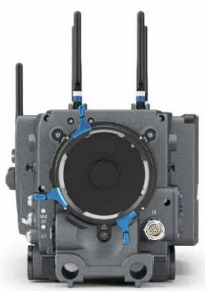
The ALEXA LF (Large Format) camera is part of a complete large-format system that meets and exceeds modern production requirements. Based around a large-format 4.5K version of the ALEXA sensor, the system comprises the ALEXA LF camera, ARRI Signature Prime lenses, new LPL lens mount and PL adapter. These system elements have been designed to take fullest advantage of the enlarged sensor, while also offering full compatibility with existing lenses, accessories and workflows.
Featuring a sensor slightly larger than full frame, ALEXA LF records native 4.5K with ARRI's best overall image quality. This allows filmmakers to explore an immersive large-format aesthetic while retaining the sensor's proven suitability for HDR and WCG workflows. Versatile recording formats, including efficient ProRes and uncompressed ARRIRAW up to 150 fps, provide unprecedented creative freedom.
ALEXA LF has the biggest sensor area of any cinema camera on the market, second only to ARRI Rental's ALEXA 65. Maintaining the ALEXA family's optimal pixel size for highest overall image quality results in a 4448 x 3096 picture, which can be recorded in full using the LF Open Gate sensor mode. An LF 16:9 sensor mode maximizes lens options while meeting 4K deliverable standards, and an LF 2.39:1 sensor mode combines a cinematic widescreen image with high frame rates for sensuous slow motion. All sensor modes offer true 800 ASA sensitivity as well as reduced noise, providing the perfect canvas for modern, subtle lighting techniques.
A crucial element of the new system is the LPL lens mount, with dimensions optimized for large format sensors. A wider diameter and shorter flange focal depth allows the ARRI Signature Primes and all future large format lenses to be small and lightweight with a fast T-stop and pleasing bokeh, a combination of features that would not be possible within the confines of the PL lens mount. The LPL mount will also be available for other ARRI cameras such as the ALEXA Mini, so the Signature Primes can be used for large format and Super 35. In addition, the LPL mount is being licensed to other lens and camera manufacturers, creating a new universal standard.
Although camera, lens mount and lenses are new, compatibility with existing PL mount lenses and ALEXA accessories is a cornerstone of the system's design. A PL adapter offers full backwards compatibility with all PL mount lenses, be they Super 35 or full frame. Since the PL adapter clips securely into the LPL lens mount without tools, crews can rapidly switch between PL and LPL lenses on set, offering an unlimited lens choice to the cinematographer. Since the ALEXA LF is based on the proven, robust ALEXA camera design, most existing accessories will work right out of the box. Since all other features and the user interface are the same as in the ALEXA SXT W, including the integrated wireless video transmitter and the user interface, crews will quickly adapt to this new camera.
ALEXA LF offers the same proven, versatile workflows as other ALEXA cameras. Recording at various resolutions is possible in uncompressed, unencrypted ARRIRAW up to 150 fps or in fast, efficient ProRes up to 100 fps. Lens metadata can be recorded from LDS-1, LDS-2 or /i capable lenses. Existing ARRI Look Files (ALF-2) can be used with ALEXA LF and the entire range of ARRI workflow software tools has been reworked to support ALEXA large-format images.
5 Layout of the ALEXA
natural_image
Close-up of a mechanical device with three antennas and blue control knobs (no visible text or symbols)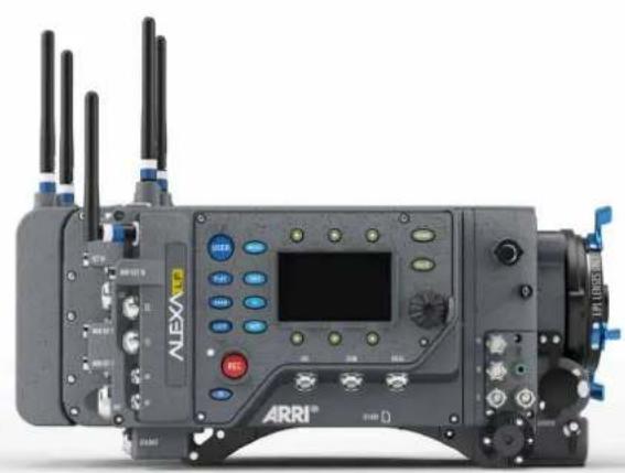
natural_image
Exterior view of a black ARRI device with multiple antennas and control panels (no readable text or symbols)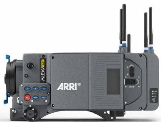
natural_image
Exterior view of an ARRI industrial machine with visible control buttons and antennas (no readable text or symbols beyond branding)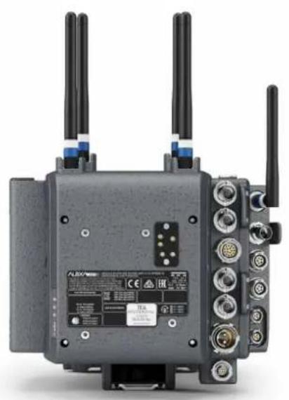
natural_image
Front view of a black wireless router with multiple antennas and ports (no visible text or symbols)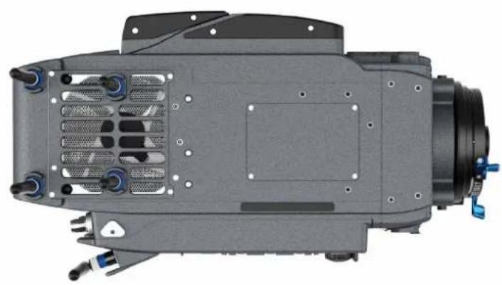
natural_image
Top-down view of a mechanical assembly with cooling fins and mounting features (no visible text or symbols)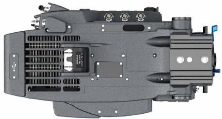
natural_image
Top-down view of a mechanical component with visible internal structure and mounting points (no text or symbols)6 Safety Guidelines
Any violation of these safety instructions or non-observance of personal care could cause serious injuries (including death) to users and affiliates and damage to the equipment or other objects.
6.1 Explanation of Warning Signs and Indications

Indicates a possible risk of injury or damage to the equipment
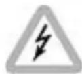
Indicates the risk of electric shock or fire danger that could result in injury or to the equipment.
NOTICE
Indicates further information or information from other instruction manuals
6.2 General Safety Guidelines

- Always follow these guidelines to ensure against injury to yourself or others and damage to the system or other objects.
- This safety information is in addition to the product specific operating instructions in general and must be strictly observed for safety reasons.
- Read and understand all safety and operating instructions before you operate or install the system!
- Retain all safety and operating instructions for future reference.
- Heed all warnings on the system and in the safety and operating instructions before you operate or install the system. Follow all installation and operating instructions.
- Do not use accessories or attachments that are not recommended by ARRI, as they may cause hazards and invalidate the warranty!
- Do not attempt to repair any part of the system! Repairs must only be carried out by authorized ARRI Service Centers.
6.3 Specific Safety Instructions

- Do not remove any safety measures from the system!
-
Do not operate the system in areas with humidity above operating levels or expose it to water or moisture!
-
Do not cover the fan openings at the camera back top and bottom!
- Do not subject the system to severe shocks!
- Do not place the system on an unstable trolley/hand truck, stand, tripod, bracket, table or any other unstable support device! The system may fall, causing serious personal injury and damage to the system or other objects.
- Operate the system using only the type of power source indicated in the manual! Unplug the power cable by gripping the power plug, not the cable!
- Never insert objects of any kind into any part of the system if not clearly qualified for the task in the manual, as objects may touch dangerous voltage points or short out parts! This could cause fire or electrical shock.
- Unplug the system from the power outlet before opening any part of the system or before making any changes to the system, especially the attaching or removing of cables!
• Do not use solvents to clean! - Do not remove any stickers or paint marked screws!
• Always place a lens or a protective cap in the lens mount receptacle! - Changing camera lenses should be done in a dry and dust-free environment. If this is not possible, take extra care that no dust enters the camera while the lens is off!
- When no lens is attached to the camera, immediately place the protective cap on the lens mount to avoid contamination of the sensor cover glass!
- After changing lenses, always perform a dust check to make sure no dust has settled on the sensor cover glass!
- Clean optical lens surfaces only with a lens brush or a clean lens cloth. In cases of solid dirt or grease, moisten a lens cloth with pure alcohol. Discard contaminated lens cloth after use! Never attempt to clean a lens brush with your fingers!
- NEVER USE CANS WITH COMPRESSED AIR OR GAS TO BLOW OFF THE DUST! This can severely damage optical elements.
- If the sensor cover glass has been contaminated by solid dirt or grease, special optical cleaning kits should be used for dirt removal under very high care! If the contamination cannot be removed, the camera should be taken to an ARRI service center for cleaning.
- THE USE OF METHANOL TO CLEAN OPTICAL SURFACES IS NOT RECOMMENDED!
• NEVER USE ACETONE TO CLEAN OPTICAL SURFACES!
• NEVER TRY TO REMOVE THE SENSOR COVER GLASS! - DO NOT POINT THE CAMERA INTO DIRECT SUNLIGHT, VERY BRIGHT LIGHT SOURCES, OR HIGH-ENERGY LIGHT SOURCES (e. g. laser beams)! This may cause permanent damage to the camera image sensor.
- DO NOT POINT THE VIEWFINDER INTO DIRECT SUNLIGHT, VERY BRIGHT LIGHT SOURCES, OR HIGH-ENERGY LIGHT SOURCES (e. g. laser beams)! This may cause permanent damage to the viewfinder display and optical elements.
- During extended operation, high data rates and/or operation at high ambient temperatures, the camera's surfaces and especially the area around the ventilation grille on top of the camera at the camera rear can get hot. Use caution and never cover, obstruct or block the fan inlets or outlets while the camera is powered.
7 General Precautions
7.1 Storage and Transport
- Use a lens port cap to prevent damage to the sensor cover glass and sensor whenever there is no lens attached.
- Unplug all cables when transporting the ALEXA in a camera case.
- Do not store the camera in places where it may be subject to temperature extremes, direct sunlight, high humidity, severe vibration, or strong magnetic fields.
7.2 Condensation

When moving the camera from a cool to a warm location or when the camera is used in a damp environment, condensation may form inside the lens port, on the sensor cover glass, between the sensor and the sensor cover glass, and on internal or external electrical connections.
Operating the camera while condensation is present may result in personal injury or damage to the equipment.
Condensation on the optical components may have a visible effect on the output images. To reduce the risk of condensation:
• Find a warmer storage location.
- If the camera needs to be stored in a place that is considerably cooler than the location where it will be used, consider keeping the camera powered from a mains unit in addition to using the air-drying cartridge.
8 Sensor related image issues
Single Frame Spots of Various Shape – also known as “Digital Dust” or “White Flecks”
Natural and/or artificial radiation may cause a “false exposure” on the image sensor. The shape of these spots may vary from dots to lines or other, sometimes irregular shapes. These spots occur in random locations of the image, last only for a single frame and are more visible in dark images. This is a principle issue of all image sensors and not a malfunction.
Flicker
Some light sources (i.e. discharge tubes or LEDs) may cause an interference with sensor exposure. This may result in image flickering or “bands” of different brightness moving up or down the image. Please note that at higher frame rates (100 fps in 50Hz countries, 120 fps in 60Hz countries) even tungsten light may flicker. A short recording and playback will show this flicker.
Rolling Shutter
Due to the rolling shutter design principle of the sensor the following effects can be observed in certain situations:
- Skewed/slanted vertical lines: fast panning or fast-moving objects may result in vertical structures to appear "skewed/slanted". The intensity of the effect depends on the relative speed of panning/object.
- Partial exposure: very short light effects (i.e. a photographer's flash or strobe light) may result in the upper part of the image showing the light effect whereas the lower part does not or vice versa.
"Black Sun"
Very bright lights (i.e. the sun, or a photographer's flash) may result in a black/magenta spot. Note: pointing the camera directly into the sun may damage the sensor.
Stuck Pixels at Long Exposure Times
At longer exposure times (longer than the standard 1/50th of a second), stuck pixels may become visible in darker image areas. The longer the exposure time the more pixels will be affected. When using exposure times longer than 1/50th of a second, carefully check your image whether the quality meets your requirements.
Stitching with ALEXA LF
The ALEXA LF sensor consists of a large sensor structure that is created by exposing two Super 35 sensor structures side by side onto a silicon wafer. This process is, somewhat misleadingly, called “stitching”. As is common with stitched large format sensors in our industry, in rare situations it is possible to notice the boundary between the left and right image halves.
9 Power Supply
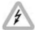
• Use only ARRI-recommended power supply solutions.
- Manipulation of power supplies could result in serious injury or death, or damage to the ALEXA.
The ALEXA accepts an input voltage range from 18.5 V to 34 V DC on the on-board battery and a range from 19.5 V to 34 V DC on the BAT connector. Do not supply power outside the specified voltage range.
In order to process the increased pixel count while still maintaining ALEXA best overall image quality, the ALEXA LF draws between 120W and 160W while recording, with EVF-1 and wireless video transmitter on, but no further accessories attached. 120W have been measured while recording ProRes 4444 in LF 16:9 sensor mode at 24 fps onto SxS PRO+ 256 GB cards. 160W have been measured while recording ARRIRAW at 90 fps in LF Open Gate sensor mode onto SXR Capture Drives. Electronic accessories will increase power draw based on the accessories' draw.
NOTICE
- The camera requires a voltage of at least 19.5 V on the BAT connector or 18.5 V on the on-board battery to power on, but it will continue running on a voltage of down to one volt less (18.5 V / 17.5 V) on the respective inputs.
- When powering accessories through the camera, the total power draw of the camera is increased by the amount of power drawn by the accessories.
- Always keep the BAT connector or attached battery accessible so that they can be unplugged quickly in case of emergency.
9.1 Power Management
When using the BAT connector and an onboard battery adapter simultaneously, the camera's power management system ensures that the power source with the highest voltage level is used. When the voltage level of one power source drops below the level of the other, or a power source is disconnected from the camera, the power management system automatically switches to the other power source, avoiding shutdown of the camera.
Note that this also means that when the onboard battery provides a higher voltage than the BAT connector, the onboard battery gets used first.
9.2 BAT Connector
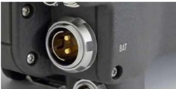
The BAT connector is the primary power input on the ALEXA. It is a Fischer 2-pin socket located at the back of the camera on the camera-right side.
The socket accepts power cables KC-20S and KC-29S. The cables can either be connected to the mains unit NG 12/26R or to 24 V cine-style batteries with three-pin XLR outputs. Do not use cables longer than 4m.
natural_image
Close-up of a black electronic device component with a metallic connector and labeled 'BAT' (no other text or symbols visible)Fig. 1: BAT connector
9.3 Mains Unit NG 12/26 R
Use of the mains unit is recommended for shooting in the studio and when using electronic accessories with high power consumption.
To power the ALEXA using the Mains Unit NG 12/26 R:
- Set the correct mains voltage on the mains unit using the fuse on the back of the unit. For example, set it to 220 V if the AC mains power source is 220 V.
- Connect the mains unit to AC mains power.
- Ensure that the camera power is turned off.
- Set the voltage switch on the mains unit to 26 V.
- Connect the battery cable KC-20S or KC-29S (spiral cable) to the power supply socket on the camera and the 26 V socket on the mains unit.
NOTICE
The NG 12/24 R was the original design that provided 12 & 24 volts output – it was superseded by the NG 12/26 R, which outputs 12 & 26 volts. The NG 12/24 R can easily be upgraded to NG 12/26 R specification at an ARRI service center.
9.4 Cine-Style Block Batteries
Any 24 V cine-style block battery with a three-pin XLR output can be used to power the camera through a KC-20S or a KC-29S battery cable connected to the camera's BAT connector. The camera will accept any voltage from 19.5 to 34 V on this connector.
To connect the battery to the camera:
- Ensure that the main switch on the camera is off.
- Connect the battery cable KC-20S or KC-29S (spiral cable) to the power supply socket (BAT) on the camera and the 24V output on the battery.
NOTICE
When the battery voltage drops below the warning level, the BAT1 level in the camera display will start flashing. A white i will appear, signaling more information is available on the INFO screen. For more information on setting the low battery warning level, see Menu>System>Power (on page 109).
9.5 Onboard Batteries
The camera can be equipped with battery adapters that accommodate a number of on-board batteries. When a battery equipped with the TI-protocol for battery communication is used, the ALEXA will display remaining capacity as a percentage on the HOME screen.
The top end of the ALEXA LF power draw at 12V can generate currents that various components in the camera/battery-adapter/on-board-battery system are not rated for. Therefore, the power input of the ALEXA LF has been set to 18.5 - 34 V for the onboard battery interface, which in turn means that the current ALEXA battery adapters for 12V Gold mount (BAB-G K2.72003.0 and BAT-G K2.72006.0) and 12V V Lock (BAB-V K2.72010.0 and BAT-V K2.72011.0) will not work with the ALEXA LF.
While many on-board battery manufacturers have solutions for the ALEXA LF now, three different adapters are available from ARRI:
• RP-CFA1: Hawk-Woods 26V Reel Power Fitting
• BAB-HG: Battery Adapter for High Load Gold Mount batteries
• BAB-HV: Battery Adapter for High Load V-Lock batteries
NOTICE
- Adapters must be installed by a trained technician.
- Use only batteries providing a current of at least 15 A for a camera setup without any accessories. When using accessories like motors or monitors, choose batteries with higher current according to the power draw of the accessories.
9.5.1 V-Lock Batteries
V-Lock batteries get their name from the characteristic v-shape of the mounting mechanism on the back of the battery.
To attach a V-Lock battery:
- Align the v-shaped wedge on the battery with the v-shaped notch on the battery plate.
- Press the battery downwards until you hear a click.
- Check that the battery is securely mounted on the battery plate.
To release a V-Lock battery:
- Press the release button on the camera-left side or top of the battery (manufacturer dependent).
- While pressing the release button, slide the battery upwards.
9.5.2 Gold Mount Batteries
Gold Mount batteries use three, typically gold colored, off-centered mounting pins to attach to the battery adapter. Their remaining capacity will be displayed as percentage on the HOME screen.
To attach a Gold Mount battery:
- Align the three pins on the back of the battery to the three corresponding holes on the battery adapter.
- Press the battery to camera-right until you hear a click.
- Check that the battery is securely mounted on the battery plate.
To release a Gold Mount battery:
- Press the release button on the camera-left side of the battery adapter.
- While pressing the release button, slide the battery camera-left, and pull it straight out.
9.6 Power Outputs
The ALEXA LF has four 24 V power outputs, two at the front and two at the back of the camera, and one 12 V power output.
For detailed information, see Chapters "RS", page 32 and "12 V", page 33.
10 Camera Support
10.1 Minimum Equipment Recommended For Operation
• ALEXA LF camera body and LPL mount
• Electronic Viewfinder EVF-1 or EVF-2
• Viewfinder Mounting Bracket
• KC 150-S Viewfinder Cable short 0.35m/1.2ft
• CCH-1 Center Camera Handle
- BP-12 Bridge Plate with base plate, or BPA-1 with BP-5/BP-8 Bridge Plate and base plate, or WA-1 Wedge Adapter and Quick Release HD Baseplate
- SD card
• Compatible power supply
• Suitable media for recording
10.2 Tripod and Remote Heads
Tripod and remote heads must have adequate load ratings to support the ALEXA and attached accessories. See the dimensional drawings and weights for your camera model in the Appendix of the manual.
NOTICE
Always check the payload limits of a remote head and crane before mounting a camera.
In applications where the camera mount is subject to high forces (e.g. car or helicopter mounts) the camera must be additionally secured with appropriate safety restraints. All mount screws must be tightened firmly with an appropriate screwdriver (not with the commonly used coin!).
10.3 Electronic Viewfinder
EVF-1
natural_image
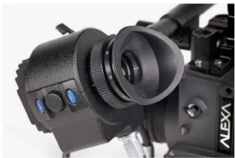
Close-up of a black Alexi camera with lens and control buttons (no visible text or symbols)The electronic viewfinder EVF-1 employs a liquid crystal on silicon (LCOS) imaging device with a temperature-stabilized LED light source to provide a bright, accurate view of the sensor image in all operating conditions. Each EVF-1 is calibrated to precisely match the image on the ALEXA's HD-SDI outputs.
The EVF-1 has a resolution of 1280x720 pixels, with 32 additional lines of resolution above and 32 below the image to display camera status information. The EVF-1 can also display a surround view area of the sensor to help the operator track unwanted elements before they enter the recorded image area. Focus can be checked by temporarily zooming into the image. The low-latency interface of the EVF-1 has a delay of less than 1 frame.
The EVF-1 has button controls for false color check and zoom, as well as buttons and a jogwheel to control EVF and camera settings.
Connect the viewfinder to the camera using the viewfinder mounting bracket.
natural_image
Exterior view of a black ARRI video camera with external camera and antenna (no visible text or symbols on body)EVF-2
natural_image
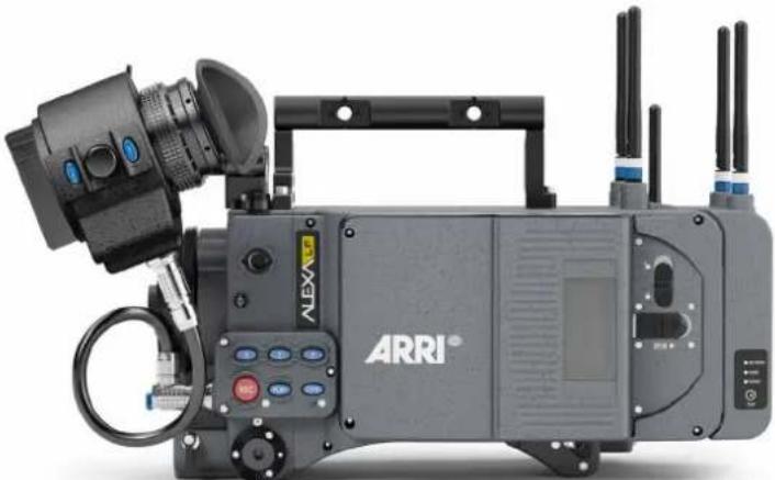
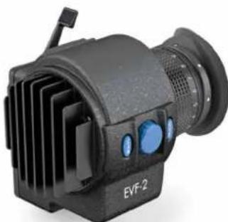
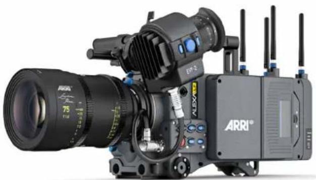
Exterior view of a black EVF-2 optical device with ventilation grilles and blue buttons (no text or symbols on body)A new and greatly improved electronic viewfinder, the EVF-2, is available as of mid-August 2018 for the ALEXA LF camera to answer customer's requests for a better way to judge focus, dynamic range and color. While still maintaining its predecessor's proven robustness, reliability and ergonomics, the EVF-2 is equipped with a new display with full HD resolution and higher contrast, greatly improving the operator's ability to judge focus and dynamic range. A new glass eyepiece based on the ARRICAM/AMIRA design provides a clean image, free of distortions and with greater freedom of movement for the operator through a wider exit pupil. The fully revamped color science further improves the image, including more accurate color rendition, a better match to on-set monitors and a stable color balance at all ambient temperatures, display brightness settings and image brightness levels. An "EVF-1 gamma" setting emulates the EVF-1 tonal behavior for situations where EVF-2 and EVF-1 are used together on set.
natural_image
Exterior view of a ARRI 75 video camera with extended lens and external antennas (no text or symbols visible on main body)NOTICE
Do not point the viewfinder into direct sunlight, very bright light sources, or high-energy light sources (e.g. laser beams)! This may cause permanent damage to the viewfinder display and optical elements. If possible, cover the eyepiece when not in use to prevent any damage.
10.3.1 Viewfinder Cables
The viewfinder cables are unidirectional with a male plug to connect to the camera and a female plug to connect to the viewfinder.
Cables are available in the following lengths:
| Model Length | (m / ft) | Suggested use |
| KC-150-S 0.35 / | 1.2 For use of EVF on camera left side in handheld mode | |
| KC-151-S 0.65 / | 2.1 For use of EVF on camera right side or when using Viewfinder Extension Bracket VEB-1 or VEB-3 |
10.3.2 Viewfinder Mounting Bracket
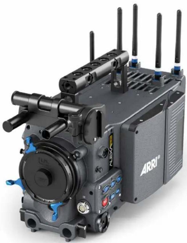
The Viewfinder Mounting Bracket VMB-3 is attached to the camera using two captive 3mm hex socket head screws on top of the camera at the front. The VMB-3 features a leveling bubble and two internally threaded 15mm rods with standard 60mm distance. These can be exchanged for or extended with standard 15mm rods for mounting matte boxes, lens motors and the like above the lens if need be.
Attach the EVF to the Viewfinder Mounting Bracket by sliding the dove tail into the receptacle and closing the lever on the EVF.
The position of the EVF can be adjusted by loosening the levers on the Viewfinder Mounting Bracket, adjusting the position as desired and closing the levers to retighten.
The EVF can be mounted on the camera-right side by unscrewing the threaded end cap on the side-to-side adjustment rod, removing the rod itself and inserting it from the other side. Remember to reattach the threaded end cap.
NOTICE
Camera-right operation is not possible with the standard EVF cable KC-150-S. Instead, the longer cable KC-151-S is needed.
natural_image
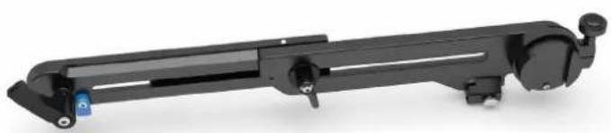
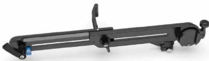
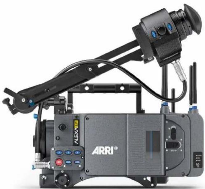
Black ARRI-branded video camera with multiple antennas and control buttons (no visible text or symbols)The Viewfinder Extension Bracket VEB-3 extends the mounting point of the EVF further back. It can be attached to a tripod head for use with geared heads or greater comfort when using fluid heads using its standard attachment point for the ARRI Eyepiece Leveler EL-3.
To avoid damage to the VMB-3 when using the VEB-3 with an eyepiece leveler, loosen the friction on VMB-3's rotating assembly.
natural_image
Mechanical assembly component with black frame and adjustment knobs (no visible text or symbols)Fig. 2: VEB-3 with closed fold-out arm
natural_image
Black mechanical device with adjustable lever and mounting bracket (no visible text or symbols)Fig. 3: VEB-3 with opened fold-out arm
natural_image
Exterior view of a black ARRI camera with articulated arm and sensor rig (no visible text or symbols)10.4 Center Camera Handle CCH-1
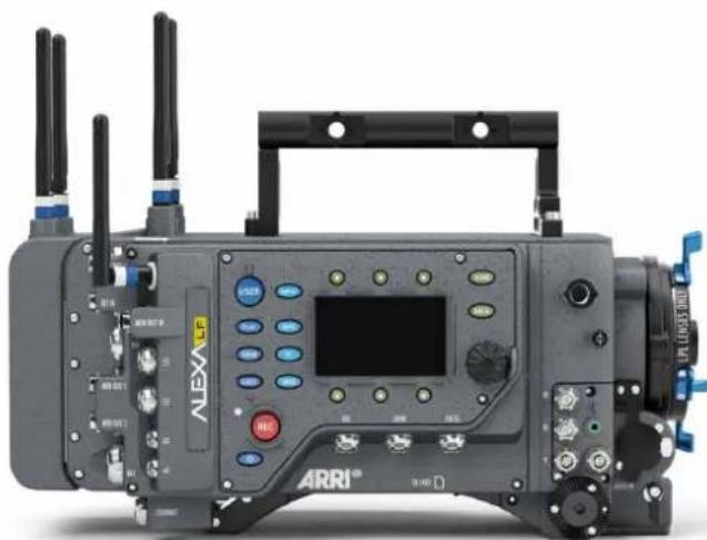
The Center Camera Handle CCH-1 is attached to the camera top with three captive 3mm hex socket head screws (two at the front and one at the back). Ensure that the CCH-1 is securely fastened before attempting to lift the camera.
natural_image
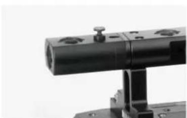
Exterior view of a black ARRI-branded industrial control device with visible ports, antennas, and control panels (no readable text or symbols beyond branding)The Handle Extension Block HEB-2 mounts to the front end of the CCH-1 and adds one more focus hook to the camera in a high position, allowing the tape measure to clear the matte box.
natural_image
Close-up of a black mechanical component with a cylindrical shaft and mounting bracket (no visible text or symbols)10.5 Bridge Plates BP-12/BP-13
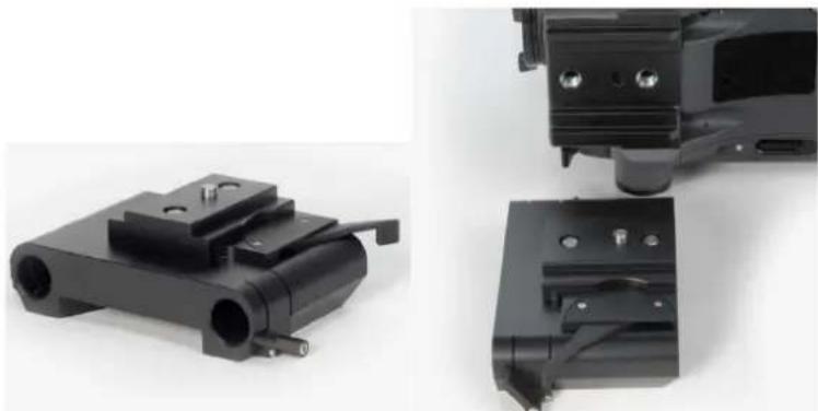
The bridge plate BP-12 for 19 mm studio rods has been specifically developed for ALEXA. It mounts directly to the camera body using two 3/8-16 screws and ensures that support rods, matte boxes and follow focus units are positioned properly in regards to the optical center of the camera, just like all other ARRI cameras.
natural_image
Close-up of two black mechanical components with mounting holes and a cylindrical housing, shown from different angles (no text or symbols visible)The bridge plate BP-13 is equivalent to the BP-12, but for 15 mm studio rods.
NOTICE
Make sure bridge plates are tightened firmly with a wide bladed screwdriver, not the commonly used coin!
10.6 Bridge Plate adapter BPA-1
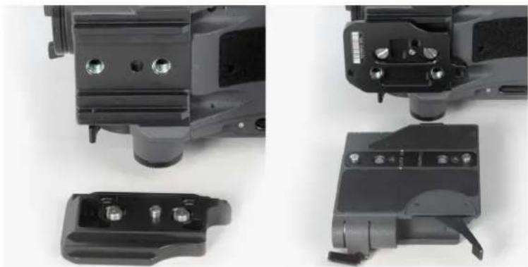
The bridge plate adapter BPA-1 can be used to attach a BP-3/BP-5/BP-8/BP-9 to ALEXA. First attach the BPA-1 to the camera with the two screws. Then attach the bridge plate to the adaptor with its two screws. Make sure the screws are tightened firmly with a screwdriver.
natural_image
Close-up of mechanical components including a cylindrical component, a black plastic housing, and a black electronic device with a handle (no visible text or symbols)10.7 Wedge Adapter WA-1 and Quick-Release Plate QR-HD-1
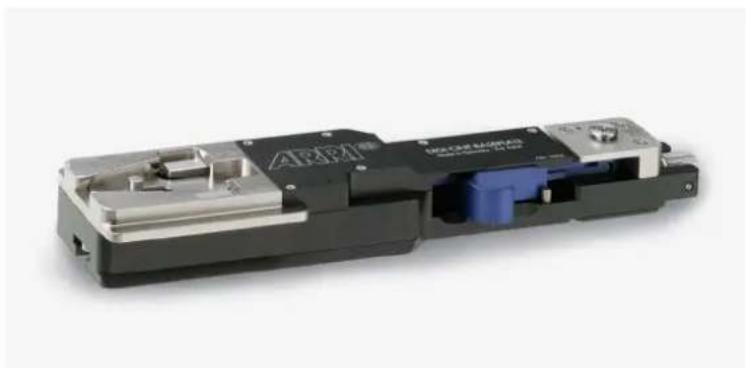
The WA-1 can be mounted at the same position as a bridge plate. It has a dove tail that slides into the counter part of a quick-release plate, like the ARRI QR-HD-1. The quick-release plate has a pin at its back, which fits into the pin receptacle at the back of the camera base.
natural_image
Close-up of a black and silver electronic device with internal components, no visible text or symbols.Fig. 4: ARRI QR-HD-1
10.8 Levelling Block LB-1
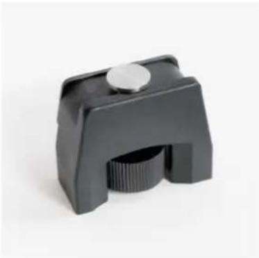
The Leveling Block LB-1 attaches to the bottom of the ALEXA in the pin receptacle on the back foot. It prevents the camera from resting on a rear-mounted battery when a bridge plate is attached and the camera is placed on a flat surface.
Attach the LB-1 by inserting its pin into the pin receptacle at the end of the shoulder arc in the camera base. Twist the knob clockwise to tighten.
natural_image
Black plastic mechanical clip with a circular cap and threaded base (no text or symbols visible)Fig. 5: Leveling Block LB-1
10.9 Shoulder Pad SP-3
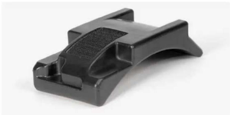
The camera base has an integrated arch to fit to the operator's shoulder. For extended handheld shots, the shoulder pad SP-3 can be attached to the base of the camera with velcro.
NOTICE
The SP-3 can only be used with a BP-12 and 19 mm rods or with 15 mm rods and a Wedge Adapter WA-1 and a Quick-Release Plate QR-HD-1. When using the BPA-1 with a BP-5/BP-8, the bridge plate has to be removed prior to attaching the SP-3.
natural_image
Black plastic mechanical component with a textured grip and curved base (no text or symbols visible)Fig. 6: SP-3 shoulder pad
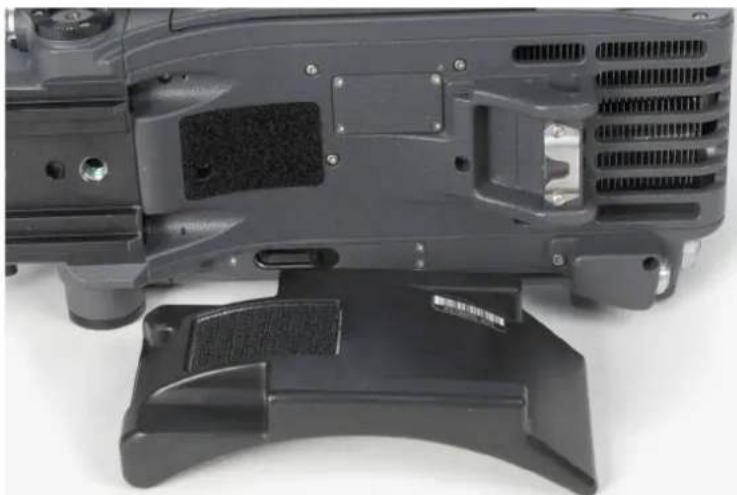
natural_image
Close-up of a black electronic device with visible internal components and mounting base (no text or symbols)Fig. 7: SP-3 below camera
11 Connectors
Camera back
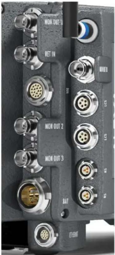
Left column
- MON OUT 1A
- RET IN
- EXT
- MON OUT 2
- MON OUT 3
BAT - ETHERNET
Right column
• ECS antenna connector
- MON OUT 1B
• LCS (2x)
• RS (2x)
Camera right
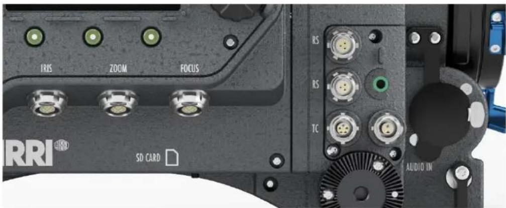
From top to bottom, left to right:
CLM connectors IRIS, ZOOM, FOCUS, SD CARD (camera bottom), 2x RS (24 V) out, TC in/out, AUDIO OUT, 12V out, AUDIO IN
Camera left
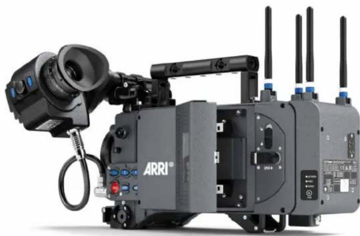
natural_image
Exterior view of a black ARRI camera with multiple wireless antennas and control panels (no visible text or symbols)Camera front

11.1 BAT
The BAT connector can be used to power the camera from an external power source with cables KC-20S and KC-29S.
It is located at the back of the camera on the camera-right side.
11.2 RET IN
A return signal from another image source can be fed into the ALEXA's RET connector for displaying on EVF and/or MON OUT. The signal must be a 1920x1080 422 1.5G single link according to SMPTE 274M and 292M. The output routing of the RET in signal can be set in the Monitoring menu.
The connector is located at the back of the camera on the camera-right side.
11.3 MON OUT 1/2/3
The MON OUT connectors are BNC connectors capable of carrying a 1920x1080 422 YCbCr 1.5G SDI signal with frame rates of 23.976, 24, 25, 29.97 or 30 fps according to SMPTE standards 274M and 292M. MON OUT 1 and 2 can also carry a 3840x2160 422 YCbCr 6G SDI signal with the same frame rates as above. The signal format can be changed in the Monitoring menu.
The connectors are located at the back of the camera on the camera-right side.
11.4 EXT
The EXT connector is a multi-pin accessory connector that carries signals for communication with various accessories and 24V power. The maximum power output is 2.2A, shared with the RS outputs.
Cables are currently available for:
- Connecting a UMC-3 remote motor controller (model UMC Connection Cable (0.80m/2.6ft) K-UMC3-ALEXA)
- Connecting two ALEXA cameras for synchronized operation (model EXT to EXT Cable (2.00m/6.6ft) KC 155-S)
The connector is located at the back of the camera on the camera-right side.
11.5 ETHERNET
Standard Ethernet connectors cannot deliver the durability and reliability required by ARRI, so the ALEXA uses a specially designed 10-pin LEMO connector. The ARRI KC-153-S cable is required to connect the Ethernet socket to a standard RJ-45 Ethernet port.
The Ethernet port can be used to operate two ALEXA cameras with synced settings by connecting the cameras with a KC 156-S cable, or to connect the Remote Control Unit RCU-4 to the camera.
The Ethernet connector can output 24 V with 1.2 A power.
The connector is located at the back of the camera on the camera-right side.
11.6 EVF
The EVF connector connects the camera to an EVF electronic viewfinder. The signals on this connector are proprietary and can only be used to drive an EVF. This proprietary signal assures low latency for the viewfinder image.
The connector is located at the front of the camera on the camera-left side.
11.7 AUDIO IN
2-channel analog line-level audio can be fed to the camera via the 5-pin XLR connector located at the front of the camera on the camera-right side.
The ALEXA converts the audio signal from analog to 24 bit 48 kHz PCM.
11.8 RS
The RS connectors can supply external devices with a combined load of up to 2.2 A (shared with the EXT connector power out), depending on the camera power supply. When the camera is powered from a source with a voltage below 24 V, they output 24 V. If the camera's power source supplies more than 24 V, this voltage level is also present on the RS outputs. Besides powering accessories, the RS outputs also carry a shutter pulse signal and can be used to send a remote start/stop signal to the camera.
The connectors are located at the front and the back of the camera on the camera-right side.
11.9 12 V
The 12 V output with a 2-pin LEMO connector is located on the right side of the camera. It is limited to 12 V and can supply a device with a current of up to 2.2 A, depending on the camera power supply.
The connector is located at front of the camera on the camera-right side.
11.10 TC
The TC connector is a 5pin LEMO socket. It accepts and distributes a Longitudinal Time Code (LTC) signal.
It can be used to
- jam-sync the ALEXA's time code to a Clockit, TC Slate or another camera
• transmit the ALEXA's time code to a Clockit, TC Slate or another camera - tune the frequency of the ALEXA's crystal oscillator with an Ambient ACC Clockit Controller
The connector is located at the front of the camera on the camera-right side.
Note that during playback, the timecode that is output via the TC connector does not match the timecode of the played clip.
11.11 AUDIO OUT
The AUDIO OUT is a 3.5mm TRS connector (headphone jack), which outputs audio fed to the 5-pin XLR AUDIO IN connector with a maximum power of 2.5 dBm.
The connector is located at the front of the camera on the camera-right side.
NOTICE
Connecting headphones to the camera while recording can cause a short audio signal interruption due to static electricity.
11.12 SD Card
The ALEXA saves data such as user setups, frame grabs and system logs to an SD card. Firmware, additional frame lines and ARRI Look File 2 files are loaded onto the camera from the SD card. The SD card slot is located on the bottom of the camera on the camera-right side. To access the SD card slot, slide the door towards the front of the camera.
SD Card Requirements
• SD or SDHC card (most brands are compatible)
• maximum capacity of 4GB
• FAT or FAT32 format
NOTICE
- Keep the SD card slot door closed to prevent dirt and moisture from entering the camera.
- After booting the camera or inserting an SD card, it might take some seconds until the SD card is recognized and usable.
The SD card can be formatted on the ALEXA or the following folder structure can be created manually on a computer. The SD card must be properly formatted prior to its first use.
SD card folder structure:
-ARRI
- ALEXA
- Firmware
- Framelines
- Grabs
-LDA
- Licenses
- LookFiles
- ScreenCaptures
- Sensor
- Setups
To format an SD card on the ALEXA:
- Press the MENU button.
- Using the jogwheel, select System.
- Select SD Card.
- Select Format + prepare SD card.
- Press both FORMAT buttons simultaneously. The ALEXA will create the required folder structure on the SD card after formatting.
NOTICE
Formatting the SD card will irreversibly remove all data on the SD card.
To create the required folder structure on the SD card in the ALEXA without formatting:
- Press the MENU button.
- Using the jogwheel, select System.
- Select SD Card.
- Select Prepare SD card. The ALEXA will create the required folder structure on the SD card without formatting or deleting any data.
NOTICE
Firmware update files are recognized by the camera anywhere within the structure, but it is recommended to copy them into the Firmware folder.
11.13 LBUS Support
LBUS Support
By connecting an LCS to LBUS cable (Cable LCS (5p) - LBUS (0.8m/2.6ft) - K2.0007318) to one of the two LCS connectors on the ALEXA LF, it is possible to use the majority of ARRI LBUS accessories with the ALEXA LF. LBUS devices can daisy chain, but it is also possible to connect one cable each to the two ALEXA LF LCS connectors to support even more LBUS devices.
LBUS accessories compatible with ALEXA LF:
• cforce mini lens motors
• cforce plus lens motors
• cforce mini RF lens motors
- Needs cforce mini RF SUP 1.1 (planned for Q4 2018)
- The cforce mini RF motor must be set to "client mode". Then it works like a cforce mini motor without the RF functionality, which the ALEXA LF has built-in anyway.
- Master Grips
- Needs at least Master Grip/OCU-1 SUP 1.1.2
- For override function it needs Master Grip/OCU-1 SUP 2.0 (planned for Q4 2018)
• Operator Control Unit OCU-1
- Needs Master Grip/OCU-1 SUP 2.0 (which is what the first OCU-1 units will be shipped with, planned for Q4 2018)
- LCUBE CUB-1
- With the CUB-1 it is possible to connect an ARRI Ultrasonic Distance Measure (UDM) to an LBUS connector. While a different cable can also connect the UDM directly to the ALEXA LF EXT connector, the CUB-1 option might come in handy if the EXT connector is in use otherwise (e.g. for sensor sync, for instance).
LCUBE CUB-2
- The CUB-2 allows an ARRI LBUS device (for instance the Master Grips or Operator Control Unit OCU-1) to control the internal motors in ENG lenses.
• emotion pan-bar zoom
• emotion steady zoom
- emotion cfinder III
NOTICE
- For OCU-1 override function, the WCU-4 needs WCU-4 SUP 3.2 (planned for Q4 2018).
CAUTION!
When using cforce motors, separate power must be provided to the cforce lens motors from the other side of the daisy chain, for instance from an LBUS to D-tap cable (LBUS - D-Tap - K2.0006758) connected to an on-board battery. This is because the power output from the ALEXA LF LCS connectors cannot provide sufficient power to the cforce motors. If cforce motors are powered from the LCS connectors, calibration may malfunction, fast motor movements may result in stuttering motor movements and a whining noise could be generated during slow motor speeds.
12 Recording Module
natural_image
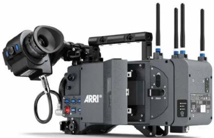
Exterior view of a black ARRI camera with multiple antennas and control panels (no visible text or symbols)The ALEXA records clips using the recording module on the camera-left side. For every recording medium type, the respective adapter needs to be inserted before a medium can be inserted. The media slot can take SXR Capture Drives with the SXR Capture Drive Adapter and SxS PRO+ cards with the SxS Adapter 2.
When the ALEXA is in ProRes mode, it can record onto SXR Capture Drives or SxS PRO+ cards. They do not need to be loaded or unloaded, but can be used directly after insertion and can be safely removed whenever they are in standby.
When the ALEXA is in ARRIRAW mode, it can only record onto SXR Capture Drives, which need to be loaded after insertion and unloaded prior to removal. Refer to the respective sections below for more information.
The ALEXA supports recording to the following media:
• SxS PRO+ cards 256 GB (SBP-256D, SBP-256E)
• SXR Capture Drives in 1 TB or 2 TB
To access the media slot, slide the OPEN slider towards camera back so that the spring-loaded door jumps open.
Putting the lock slider in the (lower) lock position prevents accidental opening of the door. Ensure that the lock slider is in the (upper) unlocked position before attempting to open the door.
NOTICE
- Keep the door closed to prevent dirt and moisture from entering the camera.
- Only Sony SxS PRO+ cards can be used with ALEXA. Sony SxS-1 and SxS PRO cards are not supported.
- SXR Capture Drives are specified for a temperature range from 0° Celsius to 70° Celsius (32° Fahrenheit to 158° Fahrenheit). When working in environments with ambient temperatures below 0° Celsius, ensure that SXR Capture Drives have a temperature of at least 0° Celsius when starting a recording to ensure proper operation.
- While we do everything we can to assure reliable functioning of different recording medias such as SXR Capture Drives, and while the mean time before failure (mtbf) for drives is excellent, a failure that results in loss of data may occur at any time. Therefore, you are obliged to implement and maintain at any time adequate and necessary data security measures and back up drive content as soon as possible. ARRI assumes or accepts no liability or responsibility for data loss or data corruption, or any other damages, loss or harm due to malfunction of recording drives.
Inserting media:
To insert an adapter:
- Insert the adapter into the media slot with the contacts facing the front of the camera and the metal housing facing out (away from the camera body).
- Push the adapter towards camera front until the two securing plastic lids lock the adapter.
To load an SXR Capture Drive:
- Insert the SXR Capture Drive into the media slot with the contacts facing the front of the camera and the ribbed side facing out (away from the camera body).
- Push the SXR Capture Drive towards camera front until the lock engages.
- Close the door.
When the camera is in ARRIRAW mode, it automatically loads the SXR Capture Drive when the door has been closed, see "Explanation of LED States" below. If closing the door is not possible, e.g. because it has been damaged, loading an SXR Capture Drive can also be triggered by pressing and holding the eject button for about five seconds.
Loading an SXR Capture Drive in ARRIRAW mode normally only takes a few seconds. In certain situations, however, it may take up to 30 seconds, especially when an SXR Capture Drive has been removed previously without unloading it properly.
NOTICE
Do not put any labels or adhesive tape on the back of an SXR Capture Drive (the side facing the camera body). The SXR Capture Drive must have full contact to the camera body to ensure proper heat conduction.
To load an SxS PRO+ card:
- Insert the card into the adapter with the contacts facing the front of the camera and the label facing out (away from the camera body).
- Push the card in against the spring until the lock engages.
- Close the door.
NOTICE
- Do not force any media into the slot or into the adapter in wrong orientation—the contacts could be damaged.
- Do not force the door closed if the media is not fully inserted.
Removing media:
When the camera is in ProRes recording mode, SxS PRO+ cards and SXR Capture Drives do not have to be mounted or unmounted—they can be inserted or removed whenever the camera is in STBY mode. If media is removed during recording, only the last second of the current clip will be lost. All clips on the media will remain accessible.
When the camera is in ARRIRAW recording mode, SXR Capture Drives need to be unloaded before they can be safely removed. Unloading is triggered automatically when the door is opened and the SXR Capture Drive is in standby. When the door is already open, but the SXR Capture Drive is still loaded, press the eject button on the SXR Capture Drive to trigger unloading. See "Explanation of LED States" below for information about how the camera signals loading state. If media is removed during recording, only the last five seconds of the current clip will be lost. All clips on the media will remain accessible.
NOTICE
- If the recording process is interrupted by power loss or media removal, transfer all the data from the media and format it before using it again.
- If the door is opened while an ARRIRAW recording is running, the camera continues running.
Before removing any media, open the door by sliding the OPEN slider towards camera back. Ensure the lock slider is in the (upper) unlocked position, otherwise the OPEN slider will be blocked.
To remove an SXR Capture Drive:
▶ Carefully pull the SXR Capture Drive towards camera back, taking care not to drop it accidentally.
To remove an SxS PRO+ card:
▶ Push the card inwards (towards camera front) until the lock disengages, then pull the card out backwards, taking care to prevent the card from dropping out of the adapter.
To remove an adapter:
▶ Carefully lift the two securing plastic tabs that secure the adapter and pull the adapter towards camera back, taking care not to drop it accidentally.
CAUTION!
It is possible that SXR Capture Drives will get hot to the touch during extended operation and can cause pain or even burns if held for too long. It is advisable to handle the drive for no more than three seconds, and to remove the drive quickly and carefully. Allow it to cool before further handling and consider wearing protective gloves.
Explanation of LED States
SXR Capture Drives and SxS Adapter 2 have an LED that signals the media's state to the user.
| LED state Media state | |
| Off | No media presentMedia is unreadable (e.g. wrong file system)Media is inactive |
| Solid green Media is in standby and ready | |
| Solid red Media is being accessed | (read/write)DO NOT REMOVE MEDIA! |
| Red flashing Media error, see camera for details | |
| Blue flashing(SXR Capture Drive only) | SXR Capture Drive is being loaded or unloaded |
| Solid blue(SXR Capture Drive only) | SXR Capture Drive is unloaded and can be ejected safely |
13 Lens Mounting
The ALEXA is equipped with an interchangeable lens mount.
NOTICE
Lenses must cover a diameter of at least 36.35 mm for LF 16:9 sensor mode, 39.76 mm for LF 2.39:1 sensor mode and 44.71 mm for LF Open Gate sensor mode to prevent vignetting.
13.1 LPL mount
The ALEXA LPL lens mount supports the ARRI Lens Data System LDS-2. An LDS lens must be mounted with the LDS contacts in the 12 o'clock position to enable the LDS functions. Take care not to damage the LDS contacts on the lens and the camera when mounting or unmounting a lens or lens port cover.
The LPL mount also offers basic Cooke /i support for direct lens metadata capture through the LDS contacts. The cameras can store a subset of /i lens data (focus distance and lens iris settings) as dynamic camera metadata. Running the camera outside the standard speeds of 23.976 to 30 fps may produce an offset of several frames. Certain lens settings will produce an offset lens data readout (e.g. iris open). This can be corrected manually, after the metadata had been extracted (ARRI Meta Extract).
The basic /i compatibility has been tested and approved by Cooke Optics Limited. For support and questions about /i Technology, please contact Cooke Optics directly.
To mount an LPL-mount lens:
- Turn the bayonet ring anti-clockwise until it stops.
- Remove the lens port cap.
- Carefully insert the lens into the lens port. Align the notch in the lens flange with the index pin on the mount, keeping the lens rotated into a position where the lens markings are visible from either side of the camera.
- Press the lens flange flat onto the lens mount.
- Turn the bayonet ring clockwise until the lens is locked securely.
- Ensure that the lens is properly mounted.
NOTICE
- When no lens is attached to the camera, use the lens port cap to prevent dust from entering the lens cavity.
- Do not short-circuit the LDS-2 contacts.
- The sophisticated design principle of the camera's optical module delivers outstanding images with a cinematic look and feel, but also makes the imager sensitive to contamination. Dust particles that have settled on the sensor cover glass during a lens change may become visible as dark spots in the output image, similar to lint leaving marks on exposed film. The degree of this effect depends on the aperture of the lens.
13.2 PL-to-LPL Adapter
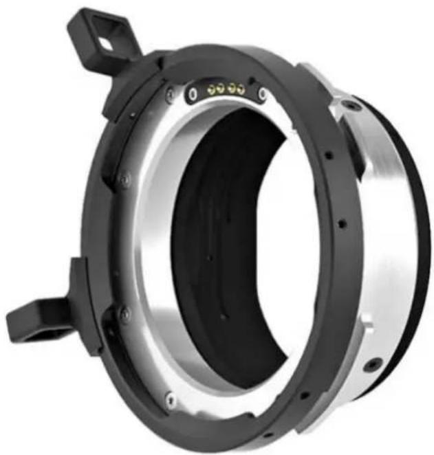
The PL-to-LPL adapter allows to attach PL lenses to the ALEXA LF without using any tools. The PL-to-LPL Adapter can be mounted with the LDS contacts in the 12:00 or 3:00 position. In both positions, it supports LDS-1 and /i.
The three most common uses of Super 35 PL lenses on the ALEXA LF are:
1 Using an image expander.
2 Cropping the Super 35 area in post.
3 Using the large illumination circle of Ultra Primes, Master Primes or Ultra Wide Zoom (UWZ).
For more information, please refer to the ARRI large format webpage (https://www.arri.com/largeformat).
Some anamorphic lenses have their lens data connectors in the 3:00 position. In this case, use a 1.5 mm hex key to reposition the orientation pin of the adapter so that the lens can be mounted correctly.
Only use PL lenses that do not exceed the dimensions defined in Chapter "Maximum lens mounting depth for PL lenses", page 44.
natural_image
Close-up of a mechanical component with concentric rings and mounting holes (no visible text or symbols)13.3 Lens Support
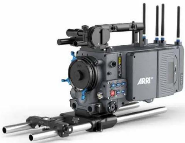
Heavy lenses may require additional lens support. Using a lens support guarantees that the weight of the lens will not influence the flange focal depth and reduces stress on the lens mount.
To support a lens use 15mm studio or 19mm studio rods and an appropriate lens bridge. 15mm studio rods require a bridge-plate with 15mm studio rod support, such as a BP-3/BP-9 + BPA-1, while 19mm studio rods require a bridge-plate with 19mm studio rod support, such as a BP-12 or BP-5/BP-8 + BPA-1.
Mount the lens bridge LS-10 for 15 mm studio rods by pushing it onto the rods from the front. Mount the lens bridge LS-9 for 19 mm studio rods by clipping it on the rods from the top.
Slide the bridge into position on the rods directly under the lens support ring on the lens, and fix it in place by tightening the lever on its side. Align and tighten the center screw in the lens support ring, adjusting the height of the center screw with the lever on the back of the lens bridge.
natural_image
Exterior view of a black ARRI camera with multiple articulated arms and control panels (no visible text or symbols)14 In-Camera Filter Module LF IFM
The In-Camera Filter Module LF IFM is standard to the ALEXA LF, which allows the use of ARRI Large Format Full Spectrum Neutral Density (LF FSND) filters (available separately).
By using internal filters you can rate the camera at the base sensitivity of EI 800 without the need for external filters, even in bright light conditions. In-camera filters for LF IFM can be used with a large variety of lens sizes and are much lighter than external ND filters.
CAUTION!
DO NOT POINT THE CAMERA INTO DIRECT SUNLIGHT, VERY BRIGHT LIGHT SOURCES, OR HIGH-ENERGY LIGHT SOURCES (e.g. laser beams)! This may cause permanent damage to the internal filter or the camera.
NOTICE
- Internal filtration requires additional shimming. For PL mount lenses, the LF IFM filters work only with a lens mounting depth of 31.50 mm maximum.
- The ALEXA LF with LPL mount must use the "ALEXA LPL LF FSND" filters.
- ALEXA Classic/XT/SXT or SXT W cameras with an LPL mount must use the "ALEXA LPL S35 FSND" filters.
- ALEXA Classic/XT/SXT or SXT W cameras with a PL mount must use the "ALEXA PL S35 FSND" filters.
Benefits of in-camera filtration
Filtering behind the lens rather than in front reduces weight, reflections and operational complexity. The filters' in-camera position significantly reduces the camera's total and front weight (because internal filters are smaller and lighter than external ones).
Also, internal filters are far less exposed to damage than external ones and, since lenses are changed more frequently than ND filters, the LF FSND filters provide extra protection for the sensor.
The Large Format Full Spectrum Neutral Density (LF FSND) filters for LF IFM are based on new technologies that assure highest image quality. An absorptive full spectrum ND coating attenuates the light while maintaining a perfectly neutral color balance at all densities.
A base of water-white optical glass, precision-polished to create perfectly parallel surfaces, guarantees a clear and sharp image.
Additional broadband anti-reflective multi-coating reduces internal reflections and ensures a high image contrast. LF FSND filters for LF IFM are available in eight densities from ND 0.3 to ND 2.4 and can be purchased separately or in sets.
All benefits at a glance:
- Internal filtration reduces reflections, weight, hassle – and filter damage
- New high-tech filters based on white-water optical glass
• Internal filtration protects sensor
• Available in 8 densities from ND 0.3 to ND 2.4 - Neutral color balance at all densities through absorptive full spectrum ND coating
• High image sharpness through precision polishing
• High contrast through anti-reflective multi-coating
• LF IFM filter holder is standard to the ALEXA LF.
14.1 Safety instructions for in-camera filtration
Proper shimming is crucial for the safe use of in-camera filters. Only correct shimming ensures the proper flange focal depth.
14.1.1 Maximum lens mounting depth for PL lenses
Only cameras with the original LF IFM Shim allow for 31.50 mm maximum lens mounting depth of PL mount lenses, when using in-camera filters.
To avoid damage or injury when using PL mount lenses with the PL-to-LPL adapter, use only lenses that do not exceed the following dimensions:
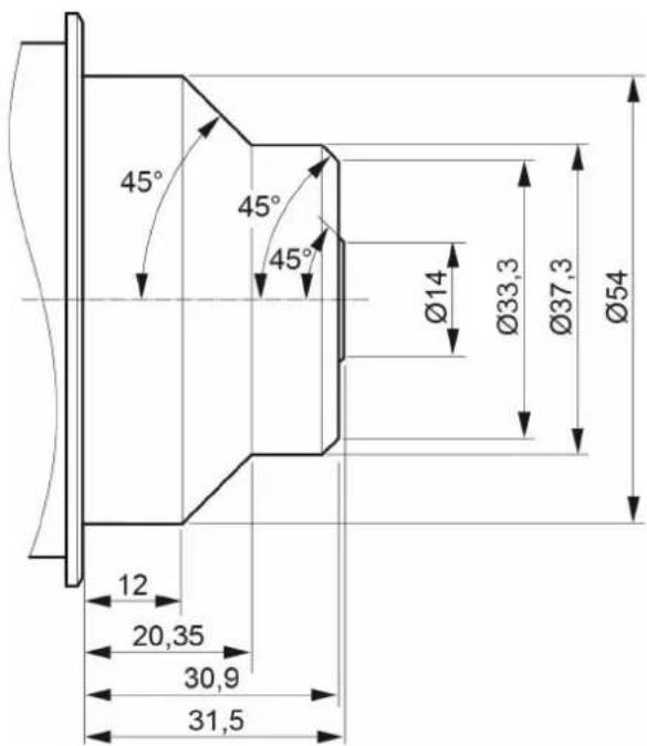
Fig. 8: Allowed lens dimensions with in-camera filters
NOTICE
The original ARRI IFM/Extenders Depth Gauge (K2.72144.0) will help you stay within allowed lens dimensions. Please ask your local ARRI Service Partner.
For a safe and correct use of internal filters, always shim your camera properly.
- Observe all precautions and use only proper tools, lenses and materials
- For PL mount lenses, use only lenses with 31.50 mm maximum mounting depth
CAUTION!
Risk of damage and injury from improper lenses!
PL mount lenses with more than 31.50 mm mounting depth might damage internal filters and the camera. Shards from broken filter glass might cause injury.
Always check the lens mounting depth before mounting or changing a lens.
CAUTION!
Risk of damage and injury from insufficient shimming!
All internal filters require a properly shimmed lens mount. Otherwise, even PL mount lenses with a nominal mounting depth of less than 31.50 mm might damage internal filters and the camera. Shards from broken filter glass might cause injury.
To ensure maximum allowable lens mounting depth, and to avoid damage or injury, always shim your camera correctly (see page 46).
The proper LF IFM Shim comes with the LF FSND Filter Set (Full) and is also available individually. Use only this original shim when filtering with LF IFM.
CAUTION!
Risk of damage from improper tools, materials or negligence!
In-camera filters are very delicate. Always handle them very carefully and with proper tools (e.g. the original Ground Glass/Frameglow tool). Never touch the filter glass with bare fingers (sweat and physical contact might damage the sensitive coating).
Check and clean each filter before and after use. Store it properly. Use only original ARRI cleansing utensils and materials (others might damage the filter).
14.1.2 Basic precautions
When using LF IFM and internal filters:
- Ensure a clean, dust-and-moisture-free environment.
- Wear fresh rubber gloves to avoid fingerprints and smear.
- Place the camera on a flat, level and safe surface.
- Never touch the sensor.
- Work very carefully due to the delicate nature of tools/components.
- Safely store all tools/components afterwards.
- Shim you camera exactly to required flange focal depth.
- Check each lens mounting depth and flange shape.
- Use only lenses within allowed dimensions.
14.1.3 Required shimming and maximum lens mounting depth
Only proper shimming will ensure the maximum allowable lens mounting depth (see page 44):
- For safe use of in-camera filters, always prepare your camera with the original LF IFM Shim.
• See "Shimming the lens mount", page 46.
14.2 LF FSND Filter Set (Full)
The LF FSND Filter Set (Full) is a set with all FSND filters and required tools. It consists of:
- Storage Case
• LF IFM Optical Clear (1) ND 0.0
• Filter Insertion Tool (2)
• 16 0.1 mm washers (3) (also available separately as K4.0000762)
• IFM/Extenders Depth Gauge DG-1 (4)
• LF IFM Shim (5)
- Microfiber Cloth (6)
• Cleaning Instructions (6)
• Eight Internal Filters LF FSND 0.3, 0.6, 0.9 1.2, 1.5, 1.8, 2.1, 2.4 (7)
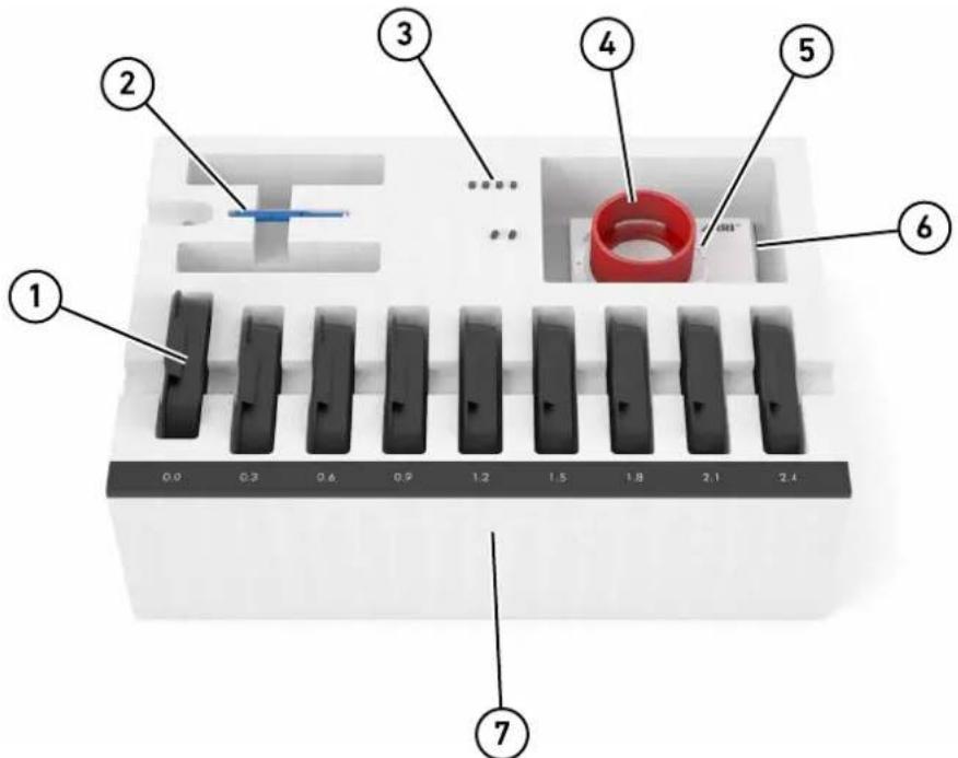
Fig. 9: The FSND Filter Set (Full) for ALEXA LF
The LF IFM Empty Filter Frame is also available separately to create custom filters. When mounting filters into the filter frame, use the provided shims to ensure the filter is sitting neither too loose nor too tight. Take special care when mounting glass filters, as the glass might break otherwise. Tighten the filter frame screws with a torque of 4 Ncm.
To insert or change a filter:
See "Mounting in-camera filters", page 52. Each filter is also available separately.
14.3 Shimming the lens mount
In-camera filtration will change your flange focal depth. Therefore, all internal filters require a properly shimmed lens mount (see page 44).
NOTICE
Use only the original LF IFM Shim when filtering with LF IFM.
To compensate for the change in flange focal depth due to the shim, always insert the LF IFM Optical Clear filter when no filtering is needed.
When the camera is no longer shimmed for LF IFM, the glassless LF IFM Empty Filter Frame must be placed back into the filter position.
General shimming precautions:
• Fix the LF IFM Shim properly between lens lock and lens mount.
• The shim's inscription must face camera-outwards.
- Mount all proper shims correctly without omitting, adding or losing any. Otherwise, the flange focal depth will not be correct.
- Mark your cameras shimmed for LF IFM to avoid confusion.
Once the camera is shimmed for LF IFM: Immediately replace the LF IFM Empty Filter Frame with an FSND filter or the LF IFM Optical Clear filter.
Store the LF IFM Empty Filter Frame in a safe place: When the camera is no longer shimmed for LF IFM in the future, the LF IFM Empty Filter Frame must be placed back into the filter position.
If you de-shim the camera: Immediately replace the LF IFM Optical Clear filter or any other FSND filter with the LF IFM Empty Filter Frame.
To compensate for the change in flange focal depth due to the shim:
▶ Always use the LF IFM Optical Clear filter when no filtering is needed.
Tools needed:
TX6 torx screwdriver
To shim the mount:
- Remove lens or lid (1) from the LPL lens mount and turn the lens lock into position CLOSED (2).
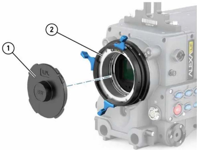
- Unscrew (only with a TX6 torx screwdriver!) the four accessible torx screws (1) that hold the lens lock (the other four torx screws are still hidden by lock position CLOSED).
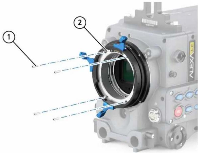
- Turn the lens lock into position OPEN (2) to unhide and unscrew the other four torx screws (1).
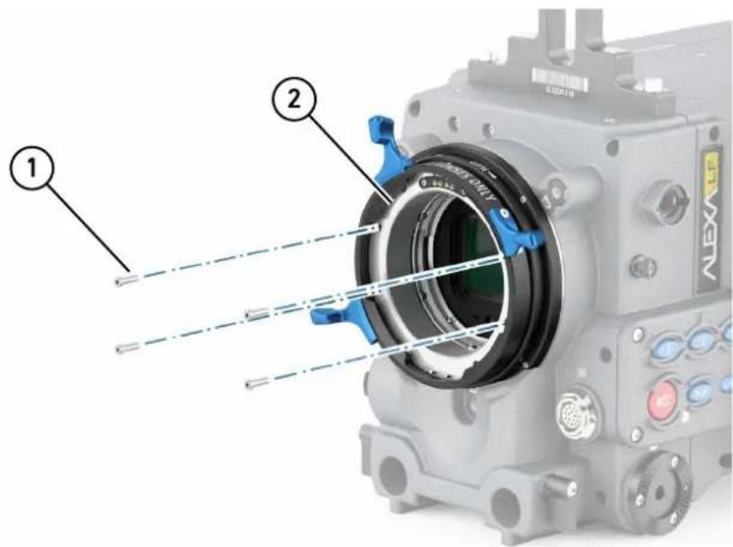
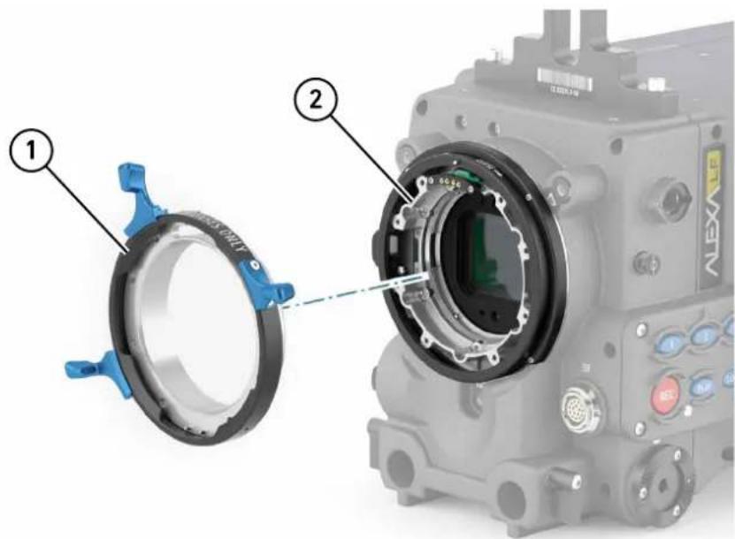
- Remove the lens lock (1) from the LPL mount. Keep all installed shims (if any) carefully in place (2):
- Remove the LDS pin support and MCA print (2) by unscrewing the two TX6 torx screws (1).
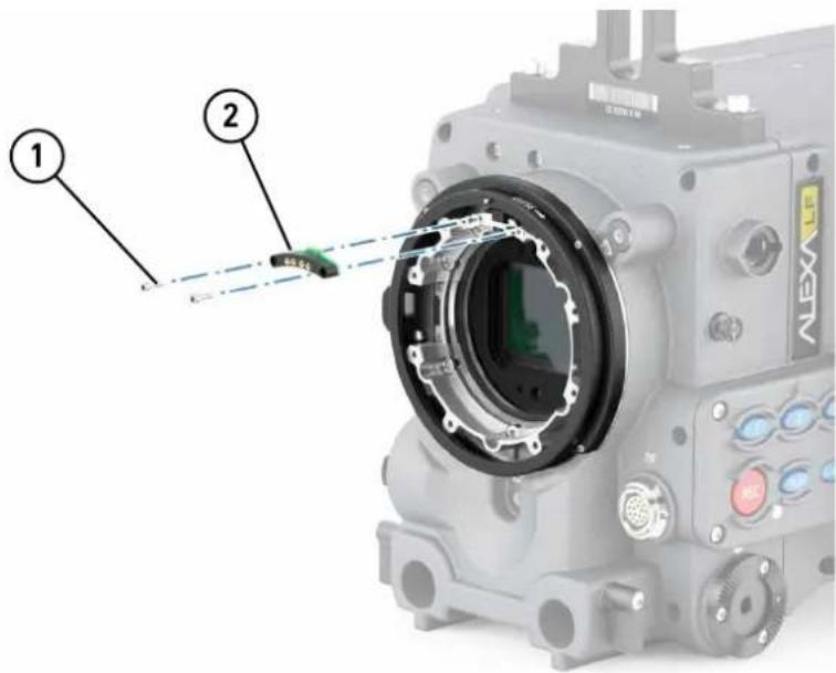
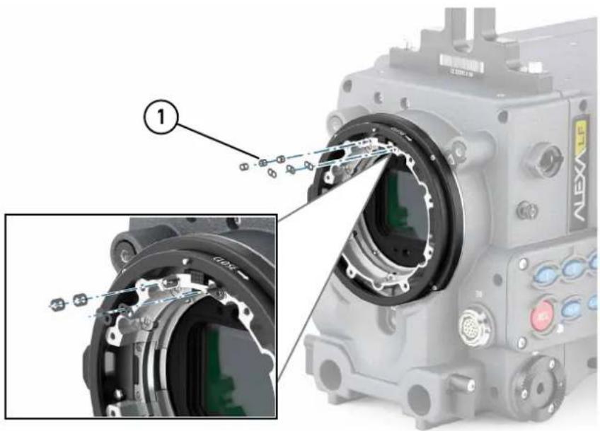
- Add three 0.1 mm washers (1) on each of the four positioning pins (see detailed section).
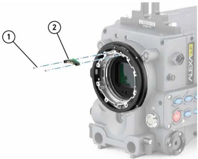
- Reattach the LDS pin support and MCA print (2) by fastening the two TX6 torx screws (1) hand-tight.
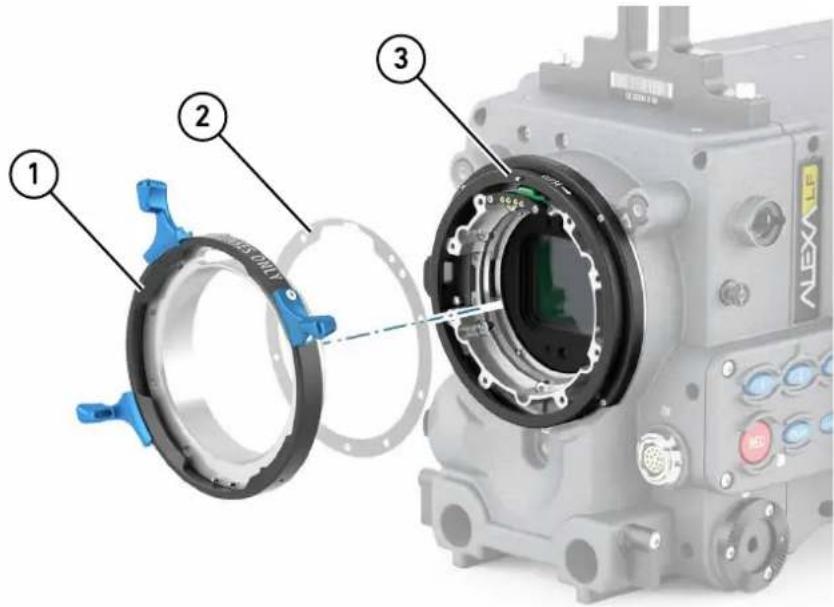
- Accurately place the LF IFM Shim, with its inscription always facing camera-outwards (2), onto the LPL mount. The shim's screw holes must line up exactly with the mount's thread holes and the index pin (3):
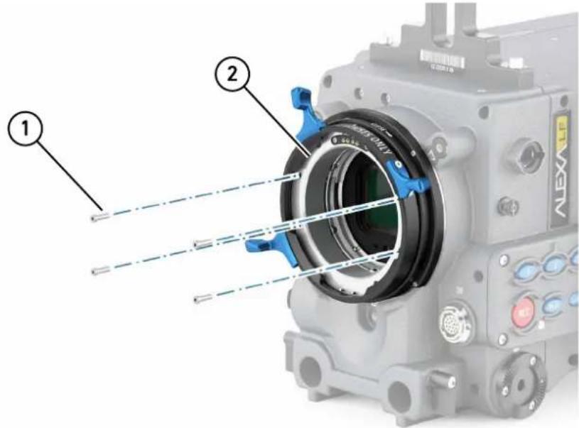
- Fasten the lens lock, still in position OPEN (2), back to the LPL mount; use four of the eight torx screws (1) hand-tight:
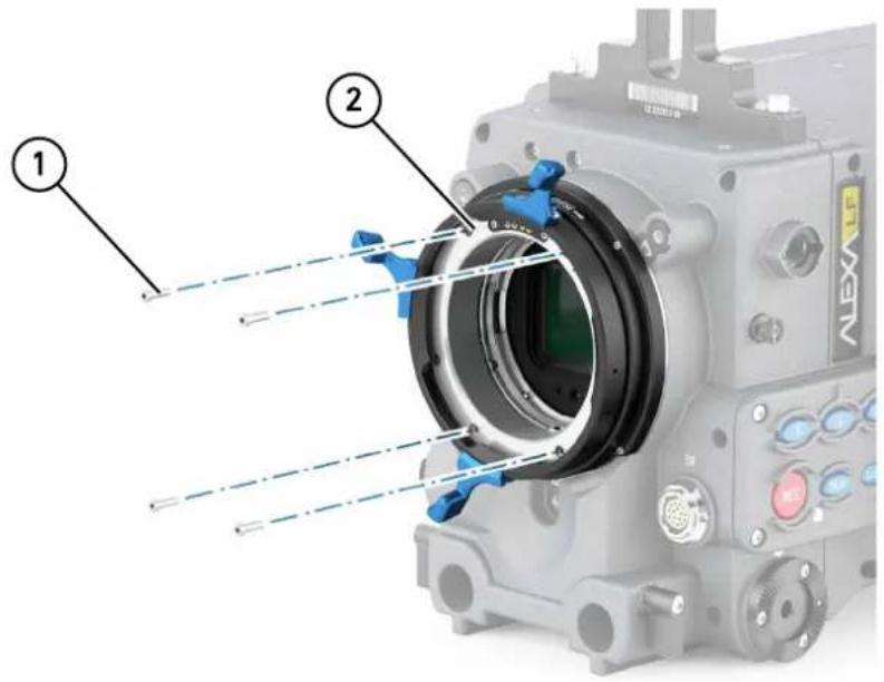
- Turn the lens lock into Position CLOSED (2) and fasten the other four torx screws hand-tight (1). Check if all screws and the shim fit correctly:
- Before mounting a lens, always check its mounting depth (see "Safety instructions for in-camera filtration", page 44 and "Maximum lens mounting depth for PL lenses", page 44)
NOTICE
Make sure the LDS connection between lens and camera's LPL mount works properly. If not, add more washers (see step 6).
14.4 Mounting in-camera filters
Internal filters are very delicate. Before you mount or change a filter, check the lens mounting depth (see "Safety instructions for in-camera filtration", page 44 and "Maximum lens mounting depth for PL lenses", page 44).
NOTICE
By default, the filter position in the lens mount of the ALEXA LF is occupied by the LF IFM Empty Filter Frame. This glassless filter ring must be replaced by a real filter or LF IFM Optical Clear filter, once the camera is shimmed for LF IFM use (see page 46)
Tools needed:
Filter insertion tool
To insert or change an in-camera filter:
- Remove the lens or lid (1) from the LPL lens mount (2).
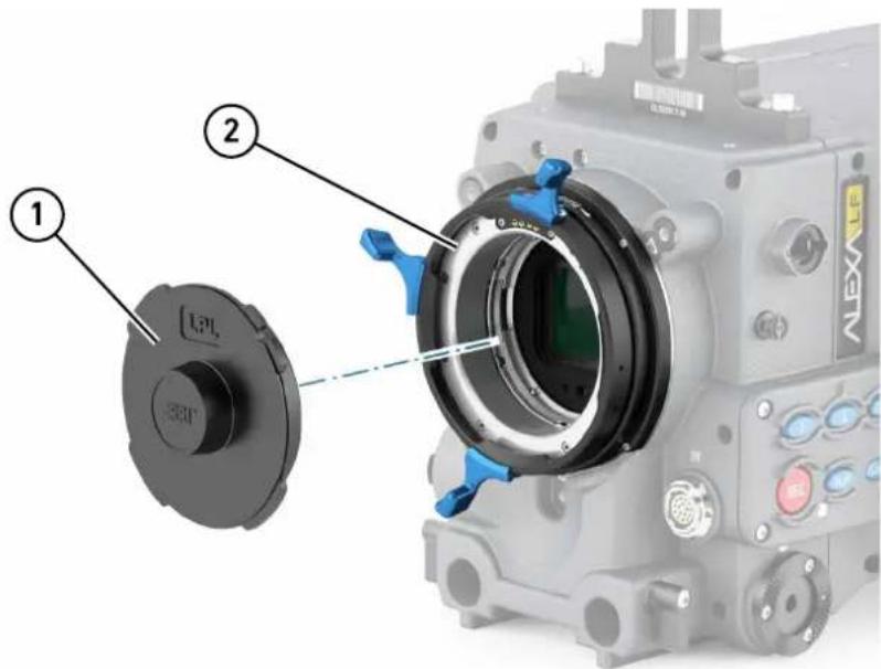
- Carefully screw the filter insertion tool (1) into the filter ring's (2) thread hole in the 12 o'clock position (1).
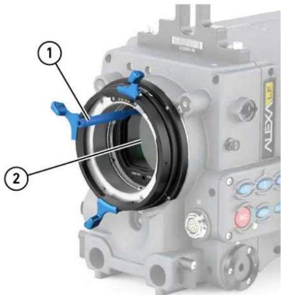
- Pull the filter (2) from the bottom ring in the camera's LPL mount. If the filter position is held by an LF IFM Empty Filter Frame, remove it likewise.
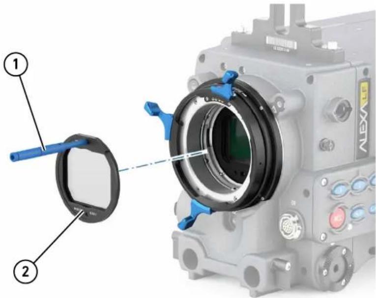
- Clean the removed filter and stow it properly in its individual box and the storage case. If the filter position was held by an LF IFM Empty Filter Frame, store it likewise (in case the camera is no longer shimmed for LF IFM in the future).
- Place the removed filter into its padded filter box in the storage case. Remove the filter insertion tool to pick up the next filter.
- Make sure the next filter (2) is clean and the filter insertion tool is in the 12 o'clock position (1).
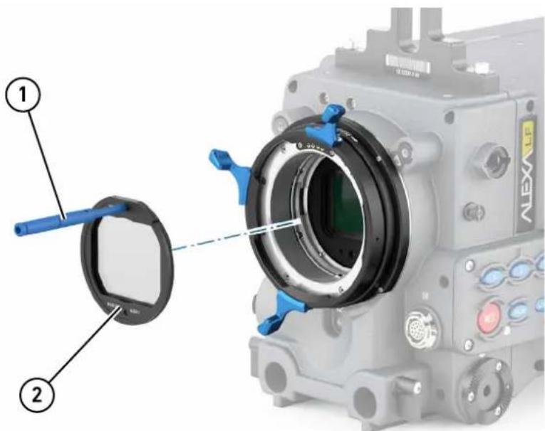
- Place the next filter onto the bottom ring in the camera's LPL mount. The filter insertion tool has to be in the 12 o'clock position (1).
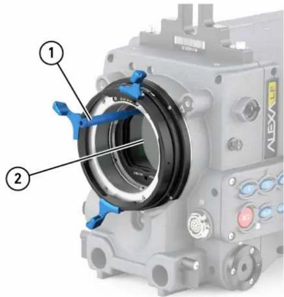
- Align the filter ring's main notch with the bottom ring's red nut in the 6 o'clock position. To ensure an accurate fit, align the filter ring's other notches with the two red noses in the bottom ring's 10:30 and 1:30 positions.
- Put your finger on the lower edge of the filter ring and push the filter ring slightly inwards, using the filter insertion tool on top and your finger on the bottom.
- After the filter ring has audibly snapped into position, carefully unscrew the filter insertion tool. The filter has to sit precisely on the bottom ring.
- Mount a lens (observe maximum lens dimensions!), or cover the LPL lens mount properly with its lid.
NOTICE
- All internal filters require a properly shimmed lens mount (see page 46).
To compensate for the change in flange focal depth due to the shim, always insert the LF IFM Optical Clear filter when no filtering is needed.
When the camera is no longer shimmed for LF IFM, the glassless LF IFM Empty Filter Frame must be placed back into the filter position.
- For PL mount lenses, LF IFM works only with a lens mounting depth of 31.50 mm maximum.
14.5 Filter cleaning
Tools needed:
- Cleaning Instructions
- Fresh rubber gloves
- Micro bellows
- Cotton swab
- Purified alcohol
• Microfiber Cloth from FSND Filter Set
To clean the filters:
NOTICE
To avoid in-camera damage, always clean all filters outside of camera.
- Ensure a clean, dust-and-moisture-free environment
- Wear fresh rubber gloves to avoid fingerprints and smear
- Never touch the sensor
- Check the coating for dirt, smear and scratches
- Remove sand, dust or solid particles with micro bellows
- Clean off oil, grease or smear with a cotton swab (or the microfiber cloth) slightly wetted in purified alcohol only
15 Camera Controls
The ALEXA can be controlled through three user interfaces:
| Main controls Location: camera-right sideInterface: 3-inch LCD-screen with floating-function buttons, a jogwheel to navigate through menus and adjust parameters, and a range of fixed-function buttons. |
| Operator controls Location: camera-left sideInterface: three assignable function buttons plus three fixed-function buttons for easy operator access. |
| EVF controls Location: Electronic Viewfinder EVFInterface: fixed function buttons and a jogwheel for adjustment of viewfinder parameters and primary shooting parameters. |
15.1 Main Controls
The main controls can be used to set all camera parameters.
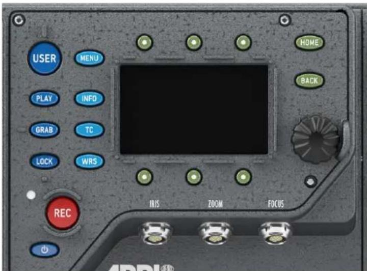
Fig. 10: Main controls
15.1.1 Display
The 3-inch LCD has a resolution of 400x240 pixels. The back-lit, transflective display has exceptional contrast even in bright sunlight.
To adjust the LCD brightness:
▶ Go to MENU>System>Display + Beeper and adjust Display brightness OR
▶ On the HOME screen, press and hold the BACK button, then turn the jogwheel.
A plastic shield protects the display from scratches. It can be removed by pulling it off the four pins.
15.1.2 Screen Buttons
Six screen buttons are located above and below the LCD display. Their function varies depending on the screen content and is shown directly above or below each button. If no function is shown above or below a button on the LCD, it has no function for that screen.
As a failsafe, operations that cannot be reversed and can result in the loss of data require pressing two buttons simultaneously to confirm the operation.
15.1.3 HOME screen
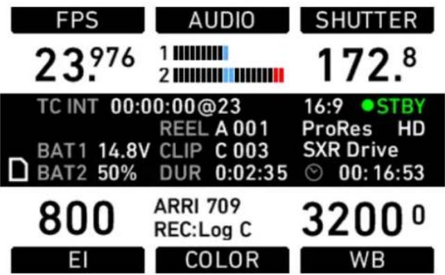
other
| Metric | Value | |--------|-------| | FPS | 23.976 | | AUDIO | 1 | | SHUTTER | 172.8 | | TC INT | 00:00:00@23 | | REEL A 001 | | | BAT1 | 14.8V | | CLIP | C 003 | | BAT2 | 50% | | DUR | 0:02:35 | | STBY | 16:9 | | ProRes | HD | | SXR Drive | | 00:16:53 | | | | | | | | | | | | | | | | | | | | | | | | | | | | | | | | | | | | | | | | | | | | | | | | | | | | | ARRI | 709 | | REC:Log C | | | | | | | | | | | | | | | | | | | | | | | | | | | | | | | | | | | | | | | | | | | | | | | | | | | | EI | Color | | | Color | | | Color | | | Color | | | Color | | | Color | | | Color | | | Color | | | Color | | | Color | | | Color | | | Color | | | Color | | | Color | | | Color | | | Color | | | Color | | | Color | | | Color | | | Color | | | Color | | WB | Color | | WB | Color | | WB | Color | | WB | Color | | WB | Color | | WB | Color | | WB | Color | | WB | Color | | WB | Color | | WB | Color | | WB | Color | | WB | Color | | WB | Color | | WB | Color | | WB | Color | | WB | Color | | WB | Color | |\( \text{BI} \) | Color | |\( \text{COLOR} \) | Color | |\( \text{SWB} \) | Color | |\( \text{STBY} \) | STBY | |\( \text{ProRes} \) | ProRes | |\( \text{HD} \) | HD | |\( \text{SXR Drive} \) | SXR Drive | |\( \text{00:16:53} \) | 00:16:53 | 3200 0The HOME screen is the ALEXA's default screen. It shows the most important camera parameters and gives quick access to changing them through the screen buttons. To return to the HOME screen from any menu in the camera, press the HOME button.
| NOTICE |
| To adjust the LCD brightness from the HOME screen, rotate the jogwheel while pressing the BACK button. |
Screen buttons
| Button Function | |
| FPS Sets the frame rate of the sensor. | |
| AUDIO Shows the current audio level. If AUDIO is set to Off, the audio input is switched off: no audio is embedded in the HD-SDI outputs, and no audio tracks are recorded onto internal media. The same applies if AUDIO is disabled, which is the case if the sensor frame rate is different from the project fps setting (for example, while over- or undercranking). | |
| SHUTTER Sets the shutter angle of the sensor. Shutter angle and sensor fps determine exposure time of the sensor in seconds by the following equation: angle / (360 * fps). | |
| EI Sets the exposure index rated in ASA. The ALEXA has a base sensitivity of 800 ASA.Note: ASA rating is identical to ISO rating.Note: Exposure Index is not applied to ARRIRAW signals. | |
| COLOR Opens the color screen, where gamma and look settings for internal recording, MON OUT 1/2/3 and EVF can be changed. | |
| WB Sets the camera | This is the color temperature of the light source that the ALEXA is currently adjusted for. In addition to the red/blue correction of the white balance, the ALEXA can also compensate for a green/magenta tint. This value, called CC (color compensation), is shown as an exponent of the WB value. Positive values are marked with a "+" and negative values with a "-".The user can execute an automatic white balance by pressing the AUTO WB button in the WB screen. |
Camera Status Section
| TC Displays the current time code including the source (INT: internal, EXT: external source). Frames are not displayed. The time-base of the time code is shown after the @ sign. | |
| BAT 1 The voltage level of the power source present at the BAT connector, or the remaining capacity of an attached battery in percentage if it transmits this information. | |
| BAT 2 The voltage level of a battery attached to the onboard battery adapter, or the remaining capacity of an attached battery in percentage if it transmits this information. | |
| REEL Identifies the current reel with the camera index letter, such as A or B and the reel number. | |
| CLIP Identifies the current clip with the clip index and clip number. | |
| DUR Displays the duration (i.e. screen time in relation to project rate) of the current clip while recording or of the last recorded clip while in standby, in the format h:mm:ss. | |
 | The camera is in standby and ready to record. |
 | The camera is recording. |
 | An error occurred and recording is not possible. Press the INFO button for more information.If nothing is shown, the camera has detected no errors, but no media is present for recording. |
| SXR Drive | Type of inserted media (SXR Capture Drive, SxS PRO) |
| 00:16:53 | During standby, shows remaining capacity of the inserted media in hours, minutes, and seconds. It is calculated for the current framerate and codec.*During recording, shows remaining length for current clip in hours, minutes, and seconds, prefixed with 'C'.Shows media status when media is not ready for recording. |
When recording is set to ProRes, the value shown is the minimum available recording time for the current sensor frame rate and codec combination. Apple ProRes™ is a variable bit rate codec, so the actual remaining recording time depends on the image content. The remaining time is updated during recording. After stopping recording, the remaining time may skip a few seconds because some media space is needed for file management.
NOTICE
- Media that has been formatted with a newer or older SUP version may not be recognized correctly and be shown as invalid, or may trigger the warning "files not consistent". In this case, backup any data from the media and format it in-camera.
- The maximum size of a single clip is limited to about 229 GB. Therefore, the camera shows a little 'C' (for clip) next to the clock icon as soon as recording starts, and it counts down the remaining time for the current recording. When the remaining time reaches zero, the camera will stop recording similar to a full medium. During standby, the camera shows the remaining capacity for the whole medium.
COLOR Section
| Day4NightREC:Log C | Name of the selected ARRI Look File 2 fileSelected gamma for recording path |
Icons
| Name Icon Description | ||
| General Warning Imp |  | information is waiting on the INFO screen. |
| General Error An erro |  | occurred. Check the INFO screen for more information. |
| Temperature Warning |  | There is a minor sensor-temperature offset. Image quality may be slightly affected. |
| Temperature Er- ror |  | There is a substantial sensor-temperature off- set. Image quality may be seriously affected. |
| Lock The Main Contr |  | locked. |
| SD Card An SD card |  | The icon turns orange when the card is accessed. |
| Grab The GRAB icon |  | a still frame is being taken and written to the SD card. |
| Radio The ARRI Wire |  | System (WRS) radio is active. |
 | The wireless network/WiFi radio is active. | |
 | The ARRI Wireless Remote System (WRS) radio and the wireless network/WiFi radio are active. |
NOTICE
A sensor temperature warning or error after boot-up is normal, as it takes a few seconds for the sensor to reach its preset temperature.
15.1.3.1 Lists and User Lists
On the HOME screen, press the FPS, SHUTTER, WB (white balance) and EI (exposure index) buttons to open lists of preconfigured values for each setting.
User-defined values can be added to the FPS, SHUTTER and WB lists. The EI list is fixed and user-defined values cannot be added. It contains values from 160-3200 ASA in steps of 1/3 stops.
Setting a list value
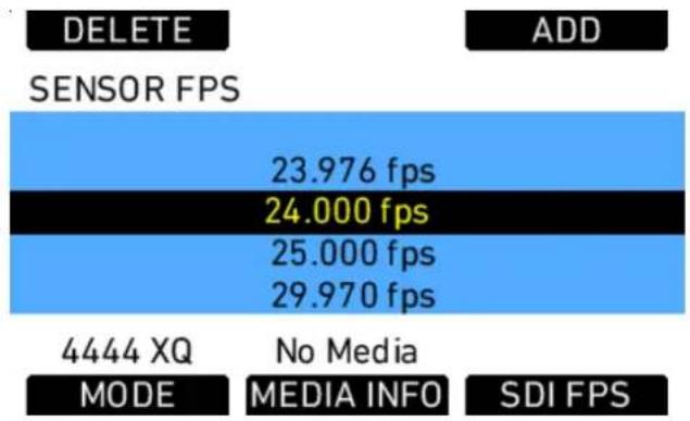
bar_stacked
| Category | Segment 1 (fps) | Segment 2 (fps) | Segment 3 (fps) | | :--- | :--- | :--- | :--- | | DELETE | 0 | 0 | 0 | | ADD | 0 | 0 | 0 | | SENSOR FPS | 23.976 | 24.000 | 25.000 | | 4444 XQ MODE | No Media | 29.970 | 0 | | MEDIA INFO | 0 | 0 | 0 | | SDI FPS | 0 | 0 | 0 |Fig. 11: SENSOR FPS screen
Any value in a list may be set. Invalid values will appear grayed out.
To set a list value:
- Rotate the jogwheel to select the desired list value.
- Press the jogwheel to set the list value.
Adding a list value
If the desired list value does not appear in the list, a user-defined value can be added.
To add a list value:
- Press the ADD button.
- On the ADD screen, use the jogwheel and + or - buttons to enter a new list value.
- When you are finished entering the new list value, press the jogwheel to add it to the list.
NOTICE
Each list supports a maximum of 16 entries. To add new user-defined list values to a full list, you must delete previously added user-defined list values.
Deleting a list value
User-defined list values that are no longer required can be deleted.
To delete a list value:
- Press the DELETE button.
- On the DELETE screen, use the jogwheel to select the user-defined value you wish to delete.
- Press both DELETE buttons simultaneously.
NOTICE
Preconfigured values cannot be deleted and will appear grayed out on the DELETE screen.
DELETE SENSOR FPS
23.976 fps
24.000 fps
25.000 fps
Default entries cannot be deleted
Figure 23: DELETE SENSOR FPS screen
NOTICE
The EI list is static and cannot be changed by the user. It contains ASA values from 160-3200 ASA in steps of 1/3 stop.
15.1.3.2 FPS
Press the FPS (frames per second) button on the HOME screen to open the SENSOR FPS list screen, which lists the default frame rates as well as user-defined frame rates.
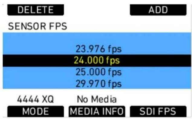
bar_stacked
| Category | MODE | MEDIA INFO | SDI FPS | | :--- | :--- | :--- | :--- | | 4444 XQ | No Media | | | | SENSOR FPS | 23.976 fps | | | | 24.000 fps | 24.000 fps | | | | 25.000 fps | 25.000 fps | | | | 29.970 fps | 29.970 fps | | | DELETE ADDNOTICE
Access to this screen is disabled during record.
The maximum frame rate that can be set is dependent on the type of media and the codec.
If the desired frame rate cannot be set because it is grayed out, change the codec to one with a lower data rate.
There are shortcut buttons on the FPS screen for CODEC, INFO and SDI FPS. In the SDI FPS screen, MON OUT 1/2/3 frame rates can be adjusted within the limits of their current format.
The MON OUT should match the sensor frame rate. If the sensor frame rate exceeds the available MON OUT frame rates, set the MON OUT to half the sensor frame rate if possible to maximize the smoothness of the image when panning and tilting.
To correctly set frame rates for the MON OUT:
- Press the MENU button.
- Using the jogwheel, select the Monitoring menu.
- Select MON OUT.
- Set Frame rate to the same frame rate as the sensor frame rate. If the sensor frame rate exceeds the range of the available MON OUT frame rates, set the MON OUT frame rate to half the value of the sensor frame rate.
- Press the HOME button to exit.
15.1.3.3 AUDIO
Press the AUDIO button on the HOME screen to open the AUDIO screen. This screen shows the ALEXA's two audio channel levels. The audio levels are displayed from -45 dBFS to 0 dBFS.
NOTICE
No audio meters are displayed on the HOME screen or AUDIO screen when audio is set to Off or audio is disabled. Audio is disabled when the sensor frame rate does not match the project frame rate. In this case, no audio is transmitted via HD-SDI.
Light blue markers show reference levels of -20, -18 and -9 dB FS.
Red markers at levels -1 and 0 dBFS warn of clipping. With proper audio signal levels, the red markers should almost never be visible.
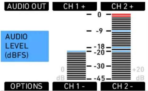
bar
| Channel | Audio Level (dBFS) | | :--- | :--- | | CH 1+ | -20 | | CH 2+ | +20 | | CH 1- | -45 | | CH 2- | -30 | | AUDIO OUT | -9 | | AUDIO LEVEL (dBFS) | -20 |Fig. 12: Audio screen
Gain can be applied to the audio channels by turning the jogwheel to set both channels, or by pressing the CH 1+, CH 1-, CH 2+ and CH 2- buttons. The amount of gain applied by the camera is indicated next to the levels as light gray numbers.
| NOTICE |
| When adjusting audio input levels, a "clicking" noise can be heard on audio outputs. Adjustment of audio levels therefore is disabled during recording. |
Press the OPTIONS button to open the AUDIO IN>OPTIONS screen and set audio parameters.
| AUDIO IN>OPTIONS | |
| Record | On |
| Channel 1 level | Manual |
| Channel 2 level | Manual |
| Channel 1 source | L in |
| Channel 2 source | L in |
| Soundroll (=Tape) | > |
Fig. 13: AUDIO IN>OPTIONS screen
| Option Description | |
| Record Turns audio recording | On or Off.If audio recording is switched off, no audio is recorded internally, HD-SDI contains no audio and Audio out is muted. |
| Channel 1 level Manual allows the user to manually apply gain to the input signal on channel 1 to reach a correct level.Unity matches a 4 dBu input signal to -20 dBFS. This setting leaves enough headroom for recording and avoids audio clipping. When Unity is selected, audio levels cannot be adjusted by the user. | |
| Channel 2 level Manual allows the user to manually apply gain to the input signal on channel 2 to reach a correct level. Unity matches a 4 dBu input signal to -20 dBFS. This setting leaves enough headroom for recording and avoids audio clipping. When Unity is selected, audio levels cannot be adjusted by the user. | |
| Channel 1 source Select the left or right input signal as the source for Channel 1. | |
| Channel 2 source Select the left or right input signal as the source for Channel 2. | |
| Soundroll (=Tape) Enter a name for the sound roll (also known as Tape in the menus of some recorders) of an external audio recorder, for easier sound syncing in post-production. The name will be written to the FCP XML file and the Avid Log Exchange (ALE) file on the recording media. | |
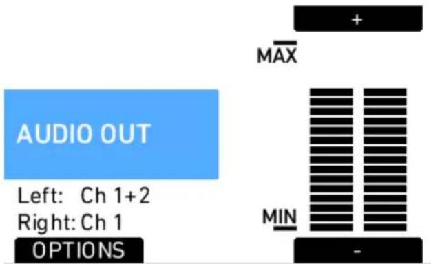
Fig. 14: Audio out screen
Press the AUDIO OUT button to open the AUDIO OUT>OPTIONS screen where the global volume for both Audio out channels can be adjusted. The OPTIONS button opens a list of AUDIO OUT options.
| AUDIO OUT>OPTIONS | |
| Left out | Channel 1+2 |
| Right out | Channel 1 |
| Audio out level | Unity max. |
Fig. 15: AUDIO OUT>OPTIONS
| Left out Sets which channel is routed to the left output. | |
| Right out Sets which channel is routed to the right output. | |
| Audio out level | Set the level of the audio out channels manually, or set it to fix the maximum output. |
NOTICE
- These settings do not influence the audio signal embedded in the HD-SDI connectors or recorded in QuickTime clips. They only affect the AUDIO OUT connector.
- ALEXA automatically determines the internal signal run time and matches audio and images so they are always in sync. When changing sensor fps or project fps, it may take up to 2 seconds for the camera to resync image and audio signals.
15.1.3.4 SHUTTER
Press the SHUTTER button in the HOME screen to open the SHUTTER ANGLE screen.
NOTICE
Access to this screen is disabled during record.
The list of default shutter angles includes 11.2°, 22.5°, 45.0°, 90.0°, 172.8°, 180.0°, 270.0° and 358.0°. User-defined shutter angles can be set by pressing the ADD button. The exposure time for the current frame rate and shutter angle is indicated in seconds at the bottom of the SHUTTER ANGLE screen.
The shutter angle range is 5.0^ to 358.0^ up to 60 fps and 5.0^ to 356.0^ above 60 fps. Below the list, the actual exposure time at the currently set frame rate is shown.
NOTICE
Be aware that the combination of long exposure times (a low sensor frame rate and large shutter angle) and high exposure indexes can lead to image artifacts! Try to avoid exposure times longer than 1/50th of a second for maximum image quality.
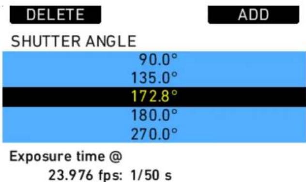
Fig. 16: Shutter list
15.1.3.5 EI
The Exposure Index (EI) is the applied sensitivity of the camera.
The ALEXA has a base sensitivity of 800 ASA. This means that the dynamic range is almost evenly distributed above and below neutral gray with low noise in the shadows and clean, smooth clipping behavior in the highlights.
Due to its high dynamic range, the ALEXA's sensitivity can be set from 160 to 3200 ASA in steps of 1/3 stops while maintaining high image quality.
EXPOSURE INDEX
| 500 ASA |
| 640 ASA |
| 800 ASA |
| 1000 ASA |
| 1280 ASA |
Fig. 17: Exposure Index screen
NOTICE
- The Exposure Index list has fixed content, meaning that it cannot be changed by the user.
- When changing the EI setting during recording, one or more frames on the recorded material may show artifacts resulting from the change.
- An area that is overexposed more than eight stops above clipping can appear darker than its surroundings.
Applying the exposure indexes at the extremes of the range will nonetheless have an influence on the images. At low exposure indexes, such as 160 ASA, the dynamic range below neutral gray increases, reducing noise even further. At the same time, the dynamic range above neutral gray is slightly reduced. Highlight clipping itself is not influenced by this, but the shoulder of the gamma curve will get slightly steeper, reducing the smoothness of the change from almost overexposed to overexposed.
At high exposure indexes, such as 1600 ASA, the images behave in the opposite way. Noise is increased, which makes it important to judge shadow detail, while there will be even more headroom in the highlights.
EI 160 ^+5.2-9.3 EI 200 ^+5.6-8.9 EI 400 ^+6.6-7.9 EI 800 ^+7.8-6.7 EI 1600 ^+8.6-5.9 EI 3200 ^+9.7-4.8
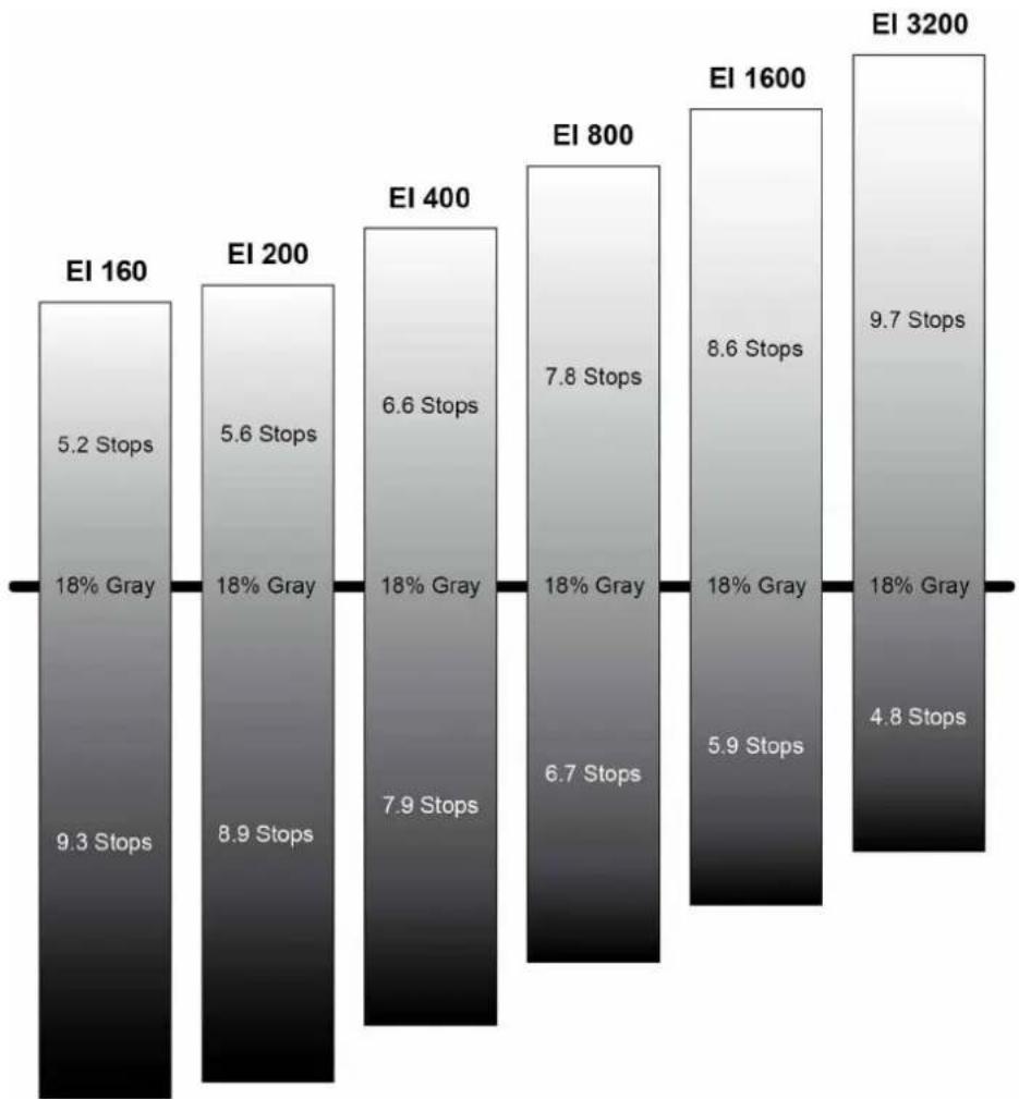
bar
| EI | Stop Count | Percentage (%) | | :--- | :--- | :--- | | EI 160 | 5.2 | 18 | | EI 200 | 5.6 | 18 | | EI 400 | 6.6 | 18 | | EI 800 | 7.8 | 18 | | EI 1600 | 8.6 | 18 | | EI 3200 | 9.7 | 18 | | EI 160 | 9.3 | - | | EI 200 | 8.9 | - | | EI 400 | 7.9 | - | | EI 800 | 6.7 | - | | EI 1600 | 5.9 | - | | EI 3200 | 4.8 | - |15.1.3.6 COLOR
The ALEXA LF comes with very powerful color processing capabilities that can be configured on the COLOR screen, similar to the ALEXA SXT. As the possible combinations of color processing parameters may become quite complex, ARRI provides a white paper titled "ARRI Look Management in ALEXA SXT", available for download on the ARRI ALEXA webpage.
Press the COLOR button to open the COLOR screen. The COLOR screen displays an overview of the color management settings applied to the camera's output paths, including:
• the current processing setting of internal recording
• a link to the processing settings of EVF and MON OUT 1/2/3
• the currently set ARRI Look File 2
• a link to the MON OUT color space configuration
If the ARRI Look File 2 file has been modified via an external Camera Access Protocol (CAP) enabled software, but is not yet saved, the look file name is appended by an asterisk.
| COLOR | |
| REC processing | Log C |
| EVF/MON processing | > |
| Look file | ARRI 709> |
| MON OUT color spaces | > |
Processing defines the type of processing that is applied to the image path. The following list describes which image processing settings are available. Note that in case of ARRIRAW recording, REC processing is always set to ARRIRAW and cannot be changed.
| Log C Log C is a | logarithmic gamma based on the Cineon format for output to film print or digital intermediate. Color-grading is a required post-production step in the Log C workflow. Standard broadcast monitors cannot properly display Log C images so a conversion look up table (LUT) is necessary for display, dailies and editing proxies. Log C images will appear flat and desaturated when displayed on standard broadcast monitors. ALEXA preview LUTs can easily be generated using the ARRI LUT Generator, a web application available on www.arri.com. |
| Look file The ARRI Look File 2 file that has been selected is applied on the respective image path. | |
| ALEXA Classic 709 | The ALEXA performs an image processing that is similar to the behavior of an ALEXA XT or ALEXA Classic with SUP 11.This setting is mainly useful if a standard REC 709 conform image should be output on the respective image path, but a more creative ARRI Look File 2 file has been loaded, e.g. for recording.This setting is not available for internal recording.Note: For technical reasons, the resulting image has very subtle differences to selecting the Look file "ALEXA Classic 709" and setting processing to "Look file". |
MON OUT color spaces
The MON OUT color spaces screen allows to configure the color space for MON OUT 1/2/3. This setting must match the color rendering capabilities of the connected monitors, otherwise color clipping may occur.
ARRI Look File 2 files
ARRI Look File 2 files are a way for the user to alter the parameters the ALEXA uses when converting the sensor image data to a video color space. This can be described as applying a custom "look" to the different image output paths. The ARRI Look File 2 file can be applied directly to the recorded image (destructive workflow), or just to the monitoring paths and included in the clip as metadata only (non-destructive workflow).
The ALEXA comes with several pre-installed ARRI Look File 2 files, including LCC 709, where LCC stands for Low Contrast Curve and 709 denotes the target color space. This ARRI Look File 2 file contains a custom tone map curve that creates a
video image with lower contrast compared to the standard REC 709 output. As a result, the image holds as much dynamic range information as possible, without using Log C encoding. Highlight and shadow detail that would be lost in the typical REC 709 tone mapping can still be accessed.
ARRI Look Creator, a free application from ARRI, and some third-party applications can be used to create ARRI Look File 2 files, which can be based on frame grabs taken with the ALEXA.
To apply an ARRI Look File 2 file:
- On the HOME screen, press the COLOR button.
- Select Look file from the menu.
- Using the jogwheel, select an ARRI Look File 2 file from the list on the LOOK FILES screen. The default preloaded ARRI Look File 2 is ARRI 709.
- Press the jogwheel to set the ARRI Look File 2.
- On the COLOR screen, set the processing to Look file.
NOTICE
If REC gamma is set to Look file, the recorded image on the internal media will be permanently altered by that ARRI Look File 2 file.
Additional ARRI Look File 2 files can be added to the ALEXA from the SD card. The ARRI Look File 2 files must be copied into the lookfiles folder on the SD card. The required folder structure on the SD card can be created via MENU>System>SD card>Prepare SD card.
To add an ARRI Look File 2 file to the camera:
- On the HOME screen, press the COLOR button.
- Select Look file from the menu.
- Press the ADD button.
- Using the jogwheel, select an ARRI Look File 2 file from the list on the LOOK FILES (SD CARD) screen.
- Press the jogwheel to add the ARRI Look File 2 file. The ARRI Look File 2 file will be added to the list on the LOOK FILES screen.
To delete an ARRI Look File 2 file from the camera:
- On the LOOK FILES screen, select an ARRI Look File 2 from the list.
- Press the DELETE button.
- Press both new DELETE buttons simultaneously. The ARRI Look File 2 file will be deleted from the camera but will remain on the SD card.
Playback and ARRI Look File 2 files
During playback, the camera makes a distinction between clips recorded in ARRIRAW, Log C, or Look processing.
When a clip recorded in ARRIRAW or Log C is played back and an output is configured for Look processing, the look will be applied to this output. Please note that this is the currently enabled ARRI Look File 2, as the camera does not take into account which ARRI Look File 2 was active when the clip was recorded. It is the responsibility of the user to make sure the correct ARRI Look File 2 is applied during playback.
When a clip recorded with Look processing is played back, no ARRI Look File 2 will be applied by the camera during playback. For the duration of that clip, ARRI Look File 2 files will be disabled.
15.1.3.7 WB
White Balance (WB) is the color balance of the camera that should be set to the value appropriate for the light in use. There are three methods for setting the white balance:
- white balance presets
• user-defined white balance
• automatic white balance
On the HOME screen, press the WB button to open the WHITE BALANCE screen. The ALEXA has the following white balance presets:
| Tungsten 3200K 0CC | |
| Fluorescent 4300K 0CC | |
| Daylight 5600K 0CC | |
| Daylight Cool 7000K 0CC |
White balance is a red-blue adjustment of the image. To adjust the green-magenta balance, use the color compensating (CC) adjustment.
For example, a fluorescent source will have peaks in its spectrum that cannot be corrected with the traditional white balance. The CC shift can correct these peaks up to a full green or full magenta gel. One step of CC SHIFT is equal to 035 Kodak CC values or 1/8 Rosco values.
| NOTICE |
| When changing the WB setting during recording, one or more frames on the recorded material may show artifacts resulting from the change. |
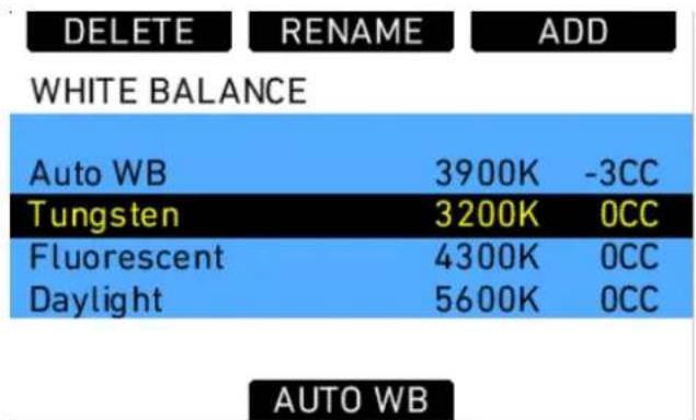
Fig. 18: WHITE BALANCE screen
ARRI recommends adjusting white balance and color compensation using appropriate measuring equipment such as a vectorscope with calibrated grey card or a color meter.
If the desired white balance setting does not appear in the WHITE BALANCE list, a user-defined white balance can be added.
To add a white balance:
- On the HOME screen, press the WB button.
- Press the ADD button.
- Rotate the jogwheel to adjust the white balance value in steps of 100K or press the +1000K and -1000K buttons.
- Press the jogwheel or <> button to select the CC adjustment.
- Rotate the jogwheel to adjust the CC value.
- Press the jogwheel to add the new white balance to the WHITE BALANCE list.
To perform an automatic white balance:
- On the HOME screen, press the WB button.
- Press the AUTO WB button.
- Place a well-lit grey card in the center of the image and press the AUTO WB button. The ALEXA will calculate the white balance and color compensation values and set these values for the "Auto WB" entry in the list.
Note: The automatic white balance will be overwritten each time a new one is calculated.
Note: If the grey card is significantly over- or underexposed, the ALEXA may not be able to calculate a white balance value and will display an error message.
- Place grey card in image center
natural_image
Simple geometric shape: a white rectangle centered within a gray rectangle (no text or symbols)- Press button to calculate Auto WB
AUTO WB
To rename a white balance:
- On the HOME screen, press the WB button.
- Using the jogwheel, select the name of the white balance you wish to rename.
- Press the RENAME button.
- Use the jogwheel to enter a new name.
- Press the DONE button to save the new name.
![Aa ERASE CLEAR ALL SET NAME A B C D E F G H I J K L M N O P Q R S T U V W X Y Z 1 2 3 4 5 6 7 8 9 0 - _ [ ] . < > DONE](/content/2026/05/882162/images/d7e4543cdaffbc63565619fcef481a70c72b037c25763e1a7d9131c6a5edbbad.jpg)
Fig. 19: WB SET NAME screen
NOTICE
Default white balance values cannot be renamed.
15.1.4 Function Buttons
The main controls feature the following function buttons:
| ON/OFF Press | once to switch the camera on. Press and hold for 5 seconds to switch off the camera. A countdown will be displayed on the HOME screen. If the button is released before the countdown has elapsed, the camera does not switch off. |
| REC Press to start and stop internal recording. | |
| LOCK Press and hold for 3 seconds to lock or unlock the main camera controls and function buttons. The recessed function buttons USER, REC and ON/OFF cannot be locked and remain available. A lock symbol on the HOME screen indicates that the lock is engaged. | |
| GRAB Press to take a still frame and write it to the SD card. The write process is indicated by a flashing camera icon, followed by a flashing SD card icon on the HOME screen. When writing is finished, a new still frame can be taken. | |
| TC Press to open the TIMECODE screen. | |
| WRS Press to open the Wireless Remote System screen. | |
| PLAY Press to open the playback screen and activate playback on MON OUT and EVF. When the playback screen is opened, the last clip on the media will be loaded automatically. | |
| INFO Press to open the LIVE INFO screen. The LIVE INFO screen displays the camera's current system state and any current error messages. On the LIVE INFO screen, there are buttons to access the following additional information screens:VERSIONMEDIASYSTEMSAVE TO SD (press to save a log file)FPS INFO | |
| USER Press to open the USER BUTTONS screen. There are six user buttons that can be assigned by the user. Buttons 1, 2 and 3 are shared with User Buttons 1, 2, and 3 in the operator controls. Press the jogwheel to see a complete list of user button options. | |
| MENU Press to open the MENU screen, where most camera settings can be adjusted. | |
| BACK Press to go back to the previous menu or screen when navigating. Press to cancel settings adjustments and revert to the previous setting. | |
| HOME Press to return to the HOME screen from any menu or screen. | |
15.1.4.1 TC
Press the TC button to open the TIMECODE screen. The TIMECODE screen displays the current timecode and timecode format settings.
SET TC
TIMECODE
00:00:00:00
Format: Int TC
Rec Run
Regen
23.976 fps
OPTIONS
PROJECT
Fig. 20: Timecode screen
NOTICE
Individual frame values are not shown but are still counted.
Press the SET TC button to set the TC counter (only when the timecode source is set to Int TC). On the SET TIMECODE screen, press the SET 2 TIME button to match the counter to the camera's system clock. Press the RESET button to reset counter to zero.
The PROJECT button is a quick link into the PROJECT menu screen, where project fps can be adjusted. Project fps sets the time base of the time code.
TIMECODE OPTIONS
Press the OPTIONS button to open the TIME CODE OPTIONS screen.
Select Source to choose the timecode source. Available sources are:
| Int TC Internal TC counter |
| Ext LTC TC is read from the LTC input. Only possible with Mode set to Free Run, and the project frame rate must match the sensor frame rate. |
Select Mode to define how the timecode is counted. Available modes are:
| Rec Run TC will | only run while recording. The TC value increases with every frame generated by the sensor while recording in the project time base. |
| Free Run TC runs free. If the source is set to Int TC, and the sensor frame rate does not match the time base of the TC, the value counts up with every new frame generated by the sensor in the project time base. | |
Select Generator to set the camera's timecode generator. Available generators are:
| Regen Rec Run | TC is regenerated from the last valid TC value. When set to Ext LTC, the camera continuously reads the TC signal at the LTC connector as long as it is present. Upon disconnection or loss of signal, the camera continues counting on its own. When the external signal is reconnected, the camera uses the values of the external signal again.When set to Int TC, the value increases with each new frame generated by the sensor. |
| Jam sync Only E | Ext LTC can be jam sync'd. To perform a jam sync, connect the external TC source to the camera. The camera then reads the external TC count and continues counting on its own; the external TC source can be removed again. The precise crystal oscillator in the ALEXA will count accurately for up to eight hours. After eight hours, perform another jam sync to prevent timecode offset.The camera can be sync'd to TC signals whose time base differs from the camera's project time base, as long as both are integer (24, 25 and 30 fps) or non-integer (23.976 and 29.97 fps) signals. It is not possible to mix integer and non-integer signals. |
NOTICE
- It is recommended to jam-sync after every shooting break to avoid the risk of losing timecode sync during a shot.
- The camera will keep its TC and TC tuning values for about 10 minutes after disconnection from the power source. If a power source is connected, the camera will remember its TC for as long as the power source is connected, even if it is switched off.
NOTICE
- The camera will force timecode to Int TC and Regen if the sensor frame rate does not match the project frame rate.
- Non-integer TC time base settings 23.976 and 29.97 are always counted as non-dropframe time code.
15.1.4.2 INFO
STATUS Info
The STATUS INFO screen displays information about the current state of the camera system. System state: Good means that all components in the ALEXA are functioning normally. Other messages can contain error messages prefixed with E:, or warnings prefixed with W:. For more information about error messages and warnings, see "Warning and Error Messages" in the Appendix.
Press the SAVE TO SD button to save a system log to the SD card. This may take up to one minute.
NOTICE
It is only necessary to save a system log if the camera experiences multiple error messages or other abnormal behavior. The system log is not a human-readable file and should be sent to an ARRI Camera Service center for analysis.
LIVE INFO
VERSION
MEDIA INFO
System state: Good
SYSTEM
SAVE TO SD
FPS INFO
Fig. 21: LIVE info screen
VERSION Info
| Cam serial no. | The serial number of the camera. |
| Cam ID Translation of the camera serial number to Base36, with an additional prefix for 3D applications. This encoding of the serial number has been chosen so it can be part of each filename while using the fewest number of characters. | |
| Firmware Version number of the currently installed camera Software Update Packet (SUP). | |
| EVF serial no. | The serial number of the Electronic Viewfinder EVF attached to the camera. |
| EVF firmware | Version number of the Electronic Viewfinder EVF firmware. |
LIVE INFO
VERSION
MEDIA INFO
Cam serial no.
1613
Cam ID
R18T
Firmware
AlexaLF_2.0:40613
EVF serial no.
2947
EVF firmware
V1.42
SYSTEM
FPS INFO
Fig. 22: VERSION info screen
MEDIA Info
| Int. Rec. Mode Current mode for internal recording. | |
| Adapter type Type of the inserted storage adapter | |
| Status Current status of internal media. | |
| Free capacity Free storage space displayed as a percentage. | |
| Max. fps current Maximum frame rate with current codec. | |
| Size Total available storage space on media | |
| Firmware version Firmware version of the media |
LIVE INFO
VERSION
MEDIA INFO
| Int. Rec. Mode | ProRes 4444 XQ |
| Adapter type | SXR Drive |
| Status | STBY |
| Free capacity | 100% |
| Max. fps current | 60fps |
| Size | 960GB |
| Firmware version | MRV6.13A |
SYSTEM
FPS INFO
Fig. 23: MEDIA info screen
SYSTEM Info
| Time/Date Current date and time. To set the date and time, press the MENU button, select SYSTEM and select DATE/TIME. | |
| Fan speed Speed of the camera's cooling fan in rotations per minute. | |
| Sensor mode | Shows the active sensor mode. |
| Sensor temperature | Current temperature of image sensor. |
| IP address IP address of the camera's Ethernet port. | |
| WiFi IP address | IP address of the camera's WiFi connection. |
| Operating time | Shows the total operating time of the camera in hours |
LIVE INFO
VERSION
MEDIA INFO
| Time/Date | 12:54:37 / 2018-02-26 |
| Fan speed | 1380 rpm |
| Sensor mode | LF 16:9 |
| Sensor temperature | 40.0°C |
| IP address | 169.254.103.43 |
| WiFi IP address | 192.168.2.11 |
| Operating time | 1075 h |
SYSTEM
FPS INFO
Fig. 24: SYSTEM info screen
FPS Info
The FPS Info screen displays an overview of the current frame rates set in the camera and the maximum frame rate possible on the media loaded in the camera at the current settings.
| Sensor fps Frames per second generated by the sensor | |
| Project fps Time | base the camera will use for counting timecode and the frame rate used for on-camera playback of internally recorded clips |
| MON OUT 1 frame rate | Frame rate output over the MON OUT 1 HD-SDI |
| MON OUT 2 frame rate | Frame rate output over the MON OUT 2 HD-SDI |
| Media max. fps current | Maximum frame rate the loaded media can record at the current codec. |
15.1.4.3 USER
Press the USER button to open the USER BUTTONS screen. There are six assignable user buttons. Buttons 1, 2 and 3 are shared with User Buttons 1, 2, and 3 in the operator controls. Press the jogwheel to see a complete list of user button options.
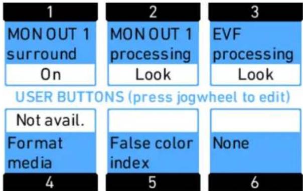
Fig. 25: USER BUTTONS screen
Assign functions to the buttons by using the jogwheel.
| 1 | 2 | 3 |
| Button 1 | MON OUT 1 surround | |
| Button 2 | MON OUT 1 processing | |
| Button 3 | EVF processing | |
| Button 4 | Format media | |
| Button 5 | False color index | |
| Button 6 | None | |
| 4 | 5 | 6 |
Fig. 26: Edit User Button assignment
The following table lists all available functions and if they can be assigned to user buttons 1-3 (identical for on-screen and buttons on camera-left side), 4-6, or both:
| Name Description 1-3 4-6 | ||
| None button has no function X X | ||
| MON OUT 1 surround | toggles surround view of the MON OUT 1 on or off | X |
| MON OUT 1 processing | toggles processing of MON OUT 1 between Log C, Look, and ALEXA Classic 709 | X |
| MON OUT 1 frame lines | toggles frame lines on the MON OUT 1 on or off | X |
| MON OUT 1 status info | toggles status info on the MON OUT 1 on or off | X |
| MON OUT 1 smart zoom | When MON OUT 1 zoom is off, switches zoom on.When MON OUT 1 zoom is on, short press toggles zoom positions, long press switches zoom off. | X |
| MON OUT 1 zoom toggles | zoom on MON OUT 1 on or off X X | |
| MON OUT 1 zoom pos | toggles zoom position on MON OUT 1 X X | |
| MON OUT 1 false color | toggles false color display on MON OUT 1 on or off | X |
| MON OUT 1 peaking toggles | peaking on MON OUT 1 on or off | X |
| MON 1 desqueeze toggles | anamorphic desqueeze on MON OUT 1 on or off | X |
| MON OUT 2 surround | toggles surround view of the MON OUT 2 on or off | X |
| MON OUT 2 processing | toggles processing of MON OUT 2 between Log C, Look, and ALEXA Classic 709 | X |
| MON OUT 2 frame lines | toggles frame lines on the MON OUT 2 on or off | X |
| MON OUT 2 status info | toggles status info on the MON OUT 2 on or off | X |
| MON OUT 2 smart zoom | When MON OUT 2 zoom is off, switches zoom on.When MON OUT 2 zoom is on, short press toggles zoom positions, long press switches zoom off. | X |
| MON OUT 2 zoom toggles | zoom on MON OUT 2 on or off X X | |
| MON OUT 2 zoom pos | toggles zoom position on MON OUT 2 X X | |
| MON OUT 2 false color | toggles false color display on MON OUT 2 on or off | X |
| MON OUT 2 peaking toggles | peaking on MON OUT 2 on or off | X |
| MON 2 desqueeze toggles | anamorphic desqueeze on MON OUT 2 on or off | X |
| MON OUT 3 surround | toggles surround view of the MON OUT 3 on or off | X |
| MON OUT 3 processing | toggles processing of MON OUT 3 between Log C, Look, and ALEXA Classic 709 | X |
| MON OUT 3 frame lines | toggles frame lines on the MON OUT 3 on or off | X |
| MON OUT 3 status info | toggles status info on the MON OUT 3 on or off | X |
| MON OUT 3 smart zoom | When MON OUT 3 zoom is off, switches zoom on.When MON OUT 3 zoom is on, short press toggles zoom positions, long press switches zoom off. | X |
| MON OUT 3 zoom toggles | zoom on MON OUT 3 on or off X X | |
| MON OUT 3 zoom pos | toggles zoom position on MON OUT 3 X X | |
| MON OUT 3 false color | toggles false color display on MON OUT 3 on or off | X |
| MON OUT 3 peaking toggles | peaking on MON OUT 3 on or off | X |
| MON 3 desqueeze toggles | anamorphic desqueeze on MON OUT 3 on or off | X |
| EVF surround^1 | toggles surround view on the EVF image on or off | X |
| EVF processing^1 | toggles processing of the EVF between Log C, Look, and ALEXA Classic 709 | X |
| Name Description 1-3 4-6 | |||
| EVF frame lines ^1 | toggles frame lines on the EVF image on or off | X | |
| EVF status info ^1 | toggles status info on the EVF image on or off | X | |
| EVF smart zoom ^1 | When EVF zoom is off, switches zoom on.When EVF zoom is on, short press toggles zoom positions, long press switches zoom off. | X | |
| EVF zoom ^1 | toggles the zoom function on the EVF X | ||
| EVF zoom pos ^1 | toggles zoom position on EVF X | ||
| EVF false color ^1 | toggles false color display on the EVF on or off | X | |
| EVF peaking ^1 | toggles peaking on the EVF on or off X | ||
| EVF desqueeze ^1 | toggles anamorphic desqueeze on EVF on or off | X | |
| Frame lines color toggles | the color of frame lines between White, Red, Green, Blue, Yellow and Black | X | X |
| Return in active toggles th | the RET IN signal on or off on the EVF and MON OUT as setScaling of RET IN signal may differ slightly depending on sensor mode and sensor frame rate | X | X |
| Phase sensor temporarily | shifts the sensor frame rate for 0.2 fps as long as the user button is pressed in order to adjust the phase of the ALEXA frame rate to an external device, i.e. a CRT monitor or a rear screen projector.Only available in standby and with timecode in rec run | X | X |
| Color bars activates color | bars on MON OUT 1/2/3 | X | X |
| Grab still frame takes a st | still frame and saves it to the SD card | X | |
| Check last clip start plays | the first 5 seconds of the last clip, then returns to a live image | X | |
| Check last clip end plays | the last 5 seconds of the last clip, then returns to a live image | X | |
| Name Description 1-3 4-6 | ||
| Circle clip marks the clip as a good takeOnly available during recording | X | |
| Auto WB Press once to open the AUTO WBScreen. Press again to perform an automatic white balance. | X | |
| Grab GUI takes a still image of the current maincamera control screen on the LCD and saves it to the SD card as a .png file in the ScreenCaptures folder | X | |
| Format media quick link to the Format media screen X | ||
| False color index displays the FALSE COLOR INDEX screen | X |
1 only available with EVF attached
15.1.4.4 PLAY
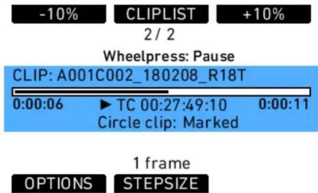
Fig. 27: PLAY screen
Clips that have been recorded internally can be played back by the camera on the EVF and all MON OUTs.
To play clips that have been recorded internally:
- Press the PLAY button.
- On the PLAY screen, the last recorded clip loads. Press the jogwheel to play the clip.
- Press the jogwheel to pause the clip.
- Rotate the jogwheel to advance the clip frame by frame, or in one second steps. Press the STEPSIZE button to toggle between seconds and frames.
- Press the +10% and -10% buttons to advance or rewind the clip by ten percent of its duration.
- Press the HOME button or BACK button to exit and output a live image over the output paths.
NOTICE
• Do not eject media during playback.
- Recorded clips do not contain the surround view portion of the EVF or MON OUT 1/2/3 image. When playing back clips, the surround view portion will not be visible.
- Playback of ARRIRAW footage may show a thin black border around the image that is not part of the recorded material.
PLAY screen buttons
| STEPSIZE Toggle the scrub step size between one frame and one second. | |
| +10% Advance the current clip by ten percent of the clip duration.Does not work when close to the end of a clip. | |
| -10% Rewind the current clip by ten percent of the clip duration.Does not work when close to the beginning of a clip. |
The jogwheel can be used to scrub through the paused clip. The scrub stepsize is shown in the lower middle section of the screen.
Additional PLAY screen information:
- clip name
- playback progress bar with current playback position in time and total clip duration
- playback timecode
• information whether the clip was marked as circle clip during recording
OPTIONS
The OPTIONS screen button opens a list of general playback options.
| Clip end action Determines what happens when the end of a clip is reached. Options are Pause and Loop. | |
| Show frame lines Sets frame lines to On or Off during playback. Center mark is always switched off during playback. | |
| Status info on MON OUT 1/2/3 | Sets status info overlays on MON OUT during playback to On or Off. |
| Peaking on MON OUT 1/2/3 | Determines whether peaking is applied to played back clips on MON OUT. Unless needed to check focus, we recommend to leave this option off as it can confuse others into thinking the peaking indication is a recorded image artifact. |
| Peaking on EVF Determines whether peaking is applied to played back clips on EVF. Unless needed to check focus, we recommend to leave this option off as it can confuse others into thinking the peaking indication is a recorded image artifact. | |
CLIPLIST
Press the CLIPLIST button to open the CLIPLIST screen and access all the clips recorded internally.
To play a clip from the cliplist:
- Press the CLIPLIST button.
- Use the jogwheel to select a clip.
- Press the jogwheel to load the selected clip.
- Press the jogwheel to play the selected clip.
Additional CLIPLIST screen information:
• number of selected and total number of clips on the media
- codec of selected clip
• duration of selected clip
- circled or not
CLIPLIST
A001C001_100830_L1JL
A001C002_100830_L1JL
A001C003 100830 L1JL
Clip 1 of 106
Dur: 0:02:35
Codec: ProRes 4444 XQ
Marked
Fig. 28: CLIPLIST screen
NOTICE
Not all clip formats can be played back in all camera modes. If a clip cannot be played back in the current camera mode, it appears grayed out. Switch the camera to the mode that was used for shooting to play back those clips.
When a clip with audio tracks is selected for playback, the audio tracks will be played back as well. In-camera playback may render a short audio distortion at the beginning or end of the clip, which is not part of the recorded audio tracks.
Playback and ARRI Look File 2 files
During playback, the camera makes a distinction between clips recorded in ARRIRAW, Log C, or Look processing.
When a clip recorded in ARRIRAW or Log C is played back and an output is configured for Look processing, the look will be applied to this output. Please note that this is the currently enabled ARRI Look File 2, as the camera does not take into account which ARRI Look File 2 was active when the clip was recorded. It is the responsibility of the user to make sure the correct ARRI Look File 2 is applied during playback.
When a clip recorded with Look processing is played back, no ARRI Look File 2 will be applied by the camera during playback. For the duration of that clip, ARRI Look File 2 files will be disabled.
15.1.4.5 Wireless Remote System
Radio System
The ALEXA LF contains a radio unit that enables wireless lens control, lens data communication and remote control of basic camera functions. The radio system is called white radio and it can be identified by a white ring at the base of the antenna mount point. It offers 8 channels to choose from:
| Channel Frequency | |
| 0 2.410 GHz | |
| 1 2.415 GHz | |
| 2 2.430 GHz | |
| 3 2.435 GHz | |
| 4 2.450 GHz | |
| 5 2.455 GHz | |
| 6 2.470 GHz | |
| 7 2.475 GHz | |
| 8 2.420 GHz | |
| 9 2.425 GHz | |
| 10 2.440 GHz | |
| 11 2.445 GHz | |
| 12 2.460 GHz | |
| 13 2.465 GHz |
White radio and legacy yellow radio cannot be mixed in the same radio network of camera and hand units. It is possible to use both systems in parallel within different radio networks.
Up to three hand units can be connected to one camera in parallel to form a radio network.
Setting the region of the wireless function
CAUTION!
Wireless region settings specify where the wireless function can be used in compliance with local regulations. It may be illegal to use the wireless function in a region other than specified in the setting. Please ensure that the region is configured correctly, e.g. when traveling.
▶ Press the WRS button. Choose RADIO > WRS REGION and select the region. You have the following options:
- Australia
- Canada
- China
- Egypt
- Europe
- Hong Kong
- India
- Israel
Japan - New Zealand
- Philippines
- Singapore
- South Africa
- South Korea
- Taiwan
- Thailand
• United Arab Emirates
• USA
World
In case of doubt please contact ARRI Service to ensure that the region is configured correctly. Note that all settings fulfill FCC requirements.
Plus Camera Controls
The WRS button gives access to the WRS screen, from where all camera settings related to the Wireless Remote System can be handled.
The WRS screen gives an overview of radio status, camera level, LDS status, and CLM status. The screen buttons lead to screens containing more detailed info on these topics and where settings can be changed.
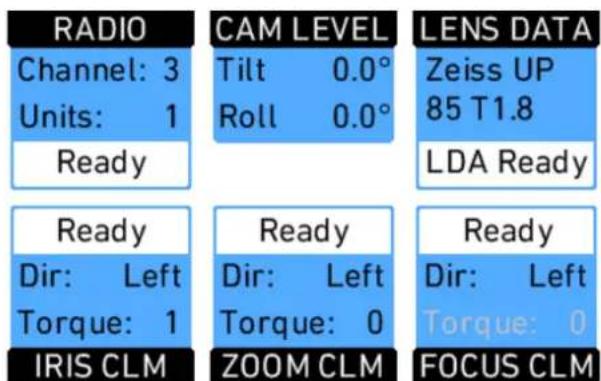
Fig. 29: WRS screen
RADIO
Shows the currently set radio channel, the number of connected hand units and the staus of the radio system. Pressing the RADIO button opens a screen where radio can be set on or off, the channel number can be set, and the WRS region can be set. When radio is switched on, a small icon appears in the camera HOME screen.
| WRS>RADIO | |
| WRS radio power | Off |
| WRS radio channel | 3 |
| WRS region | World |
Fig. 30: WRS radio screen
CAUTION!
WRS region settings specify where the wireless function can be used in compliance with local regulations. It may be illegal to use the wireless function in a region other than specified in the setting. Please ensure that the region is configured correctly (e.g. when traveling).
CAM LEVEL
Shows the tilt and roll of the camera in degrees as measured by the camera's position sensor. This sensor can be reset if it appears to have an offset. Press the CAM LEVEL screen button to access the reset screen. By pressing the two lower outer screen buttons simultaneously, the sensor is reset.
NOTICE
The sensor can only be reset while both axis are within a threshold of +/-10 degrees around 0.
For legal reasons, roll and tilt values in recorded metadata are set to a fixed, invalid value.
1. Level camera
Tilt: 0.0° Roll: 0.0°
Reset threshold OK
2. Reset motion sensor
Press both buttons!
RESET
RESET
Fig. 31: Motion sensor reset screen
LENS DATA
85.0mm t 16.5
1.0m
4.8m
3.1m
UP 85 T1.9
OPTIONS
LDA
Fig. 32: LDS info screen
Shows the type of LDS lens connected and the LDS status. The LENS DATA screen button leads to the LDS screen, where lens type, current focal length, iris, focus distance and close and far point of depth of field are shown.
The OPTIONS screen button opens the LDS options screen, where the following parameters can be set:
| Lens distance unit | MetricImperialDefault unit (as provided by the lens) |
| Circle of confusion | 0.013 mm0.025 mm0.035 mm0.050 mm |
| LDS mount | OnOff |
| Lens squeeze factor Link to the Project menu | |
NOTICE
- When setting LDS mount to Off, it is possible to use a lens table from the Lens Data Archive (see below) with an LDS lens, and ignore data coming from the lens itself. To re-enable the LDS mount, set the parameter to On, detach the lens and re-attach it.
- After connecting a new LDS lens, turn all lens rings slowly until all lens axes have transmitted their current positions.
- Cooke /i lenses need to have a firmware version of 0.39 or higher to work properly with the camera.
LDA
When a non-LDS lens is connected, the user can achieve LDS functionality by using the Lens Data Archive. In the LDS screen, a button labeled LDA appears when a non-LDS lens is connected.
The LDA screen consists of a user list and a main archive list. The user list should only contain the lenses currently used to achieve quick access to the desired lens tables. The main archive contains a set of lens tables for ARRI/Zeiss High Speeds (also known as Super Speeds), Master Primes and Ultra Primes and can be extended with additional lens tables for any PL-Mount lens.
NOTICE
Custom lens tables may have to be created manually beforehand.
Pressing the LDA button opens the User LDA screen. Select a lens table and press the wheel. After calibrating the lens motors, the LDS functionality can be used.
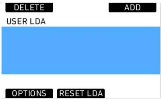
Fig. 33: USER LDA screen
To add a lens table from the main archive, access the User LDA screen and press the ADD button. This opens the MAIN LDA screen. From the main archive, first select a lens type, then a lens model and then a lens class. The lens class can be found on the lens barrell below the infinity symbol of the focus scale. Select to add the lens table to the user list (Press ADD), use it without adding (USE), or both (ADD+USE).
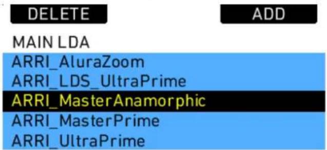
Fig. 34: Main LDA screen
To delete a lens table from the user archive, access the user list and press the DELETE button. Select the lens table to delete and press the two buttons labelled DELETE simultaneously.
Custom lens tables can be added to the main archive via the SD card. Place the lens table on the SD card in a folder named "LDA". Insert the SD card into the camera. Go to the main archive list and press ADD. Select the desired lens table and press the wheel. The lens table will be located in the main archive as lens type "Custom".
It is possible to inverse the iris, zoom and focus scales for lens tables if necessary. Press OPTIONS on the USER LDA screen to access the LDA OPTIONS screen, where these adjustments can be made.
Lenses can also be equipped with the lens data mount LDM. The mount contains a chip with the lens table stored inside, so the lens transmits its data to the camera as soon as it is connected. For information on current ring positions, these lenses must be used in combination with controlled lens motors.
CLM screens
The screens for IRIS, FOCUS and ZOOM controlled lens motors all have the same layout. They show the motor type, motor direction, motor torque, and motor teeth count mode.
NOTICE
For CLM-2 motors the torque value is greyed out as torque is only active for CLM-3, CLM-4, CLM-4 Plus, or CLM-5 motors. It can nonetheless be changed in case a CLM-3, CLM-4, CLM-4 Plus, or CLM-5 motor might be used but is currently not at hand.
In addition, a lens motor calibration can be triggered, either for all lens motors, or only for the one featured in the particular screen.
NOTICE
When starting a motor calibration, make sure each motor's gear wheel is connected properly to the lens. Pay extra attention that no one is close to the motors or holding them. Catching a finger, cloth or anything else on the motor's gear wheel can cause severe body harm as well as damage to the system (and not to mention hurt like hell).
The image below shows the FOCUS CLM screen:
CALIBRATE
DIRECTION
+1
FOCUS CLM
CLM-4
DIRECTION
Left
TORQUE
0
Teeth mode: Auto (50t)
CAL. ALL
TEETH
-1
▶ Press CALIBRATE to start calibration of the selected motor.
▶ Press CAL. ALL to start calibration of all motors simultaneously.
▶ Press DIRECTION to toggle motor direction between Left and Right.
▶ Press TEETH to toggle motor teeth count between:
• Auto (detected teeth count in brackets)
40t
50t
60t
▶ Press +1 or -1 to adjust motor torque.
Lens Motors
The ALEXA LF supports ARRI CLM-2, CLM-3, CLM-4, and CLM-5 motors and the LDE-1. CLM-1 motors are not supported. CLM-2, CLM-3, CLM-4, and CLM-5 motors can be used in a mixed setup.
NOTICE
• Use only one lens motor per lens axis.
Lens motors should be connected, according to their position on the lens, to the IRIS, FOCUS and ZOOM sockets on the camera-right side.
It is also possible to connect LBUS motors like the cforce mini with an LCS-to-LBUS cable via the LCS connectors at the camera back.
Motor calibration
After connecting a lens motor to the camera and the lens, it must be calibrated. The lens motor must be recalibrated under the following conditions:
- when the lens motor is detached from the lens
• after a camera reboot
• after changing lenses
• after a change in motor position while powered down
NOTICE
Omitting motor calibration might lead to damage of the lens due to the high level of motor torque.
To calibrate a motor:
- Press the WRS button.
- Select a motor by pressing the IRIS CLM, ZOOM CLM or FOCUS CLM button.
- Press CALIBRATE to start calibration of this motor only, or CAL. ALL to start calibration of all motors.
Motor direction
The direction of the motors can be set in the ALEXA's menus.
To set the direction of a motor:
- Press the WRS button.
- Select the motor by pressing the IRIS CLM, ZOOM CLM or FOCUS CLM button.
- Press the LEFT or RIGHT button to set the direction of the lens motor.
Motor torque
For all supported motors except for CLM-2 motors, the motor torque can be set in the ALEXA's menus.
To set the torque on a lens motor:
- Press the WRS button.
- Select the lens by pressing the IRIS CLM, ZOOM CLM or FOCUS CLM button.
- Press the +1 or -1 buttons to increase or decrease the motor's torque. Available torque settings are 1 to 4, with 1 being the lowest torque level.
NOTICE
Ensure that the motor torque level matches the lens to avoid lens damage.
3D lens sync
When two ALEXA LF cameras are set to Sensor sync EXT master and EXT slave, the slave camera will switch off its radio module and receive motor control commands from the master camera over the EXT connection.
NOTICE
- Matching of the master and slave cameras' lenses in terms of focus, iris and zoom ring positions depends on the mechanical accuracy of the lenses. Make sure the lenses in use are matched as closely as possible. Use only lenses of the same focus classification to minimize positional errors. Deviating focus positions of non-matching lenses cannot be compensated.
- At higher focus distances, even a very small position error of the lens ring results in a great difference of indicated focus values. Therefore, even a pair of matching lenses in a 3D lens sync setup may show different focus values.
Lens Data Encoder LDE-1
The LDE-1 generates lens data in situations when an ALEXA LF is being used without an LDS lens or an ARRI lens motor. Thus the LDE-1 extends the abilities of the ARRI Lens Data System to all lenses and cameras setups. The LDE-1 contains an encoder that delivers lens data to the camera and can be used in parallel with a manual follow focus unit or a third-party wireless lens control system.
Hand Units
For detailed information of the hand units, please refer to the device's own manuals.
Wireless Compact Unit WCU-4
The WCU-4 is an all-inclusive and yet affordable hand unit offering up to 3-axis lens control. It includes a newly designed, super-smooth focus knob with adjustable friction and backlit, optionally pre-marked focus rings that are well readable in the dark without distracting performers. The whole unit is completely splash proof for ARRI-typical reliability. The slider has its scale on the 3" display, providing clearly readable T-stop numbers and optional on-screen markings. If preferred, the slider can be also set to show zoom scales. With the additional ALEXA Remote license, the WCU-4 shows extended camera status information and allows to change camera parameters from the remote unit.
Single Axis Unit SXU-1
The Single Axis Unit SXU-1 is a simple single channel hand unit that can be set up to control focus, iris or zoom. It can be used along the WCU-4 for separate iris control, perhaps operated by the cinematographer in situations where subtle exposure adjustments are required during travelling shots.
Master Grips
Master Grips combine effective camera stabilization with flexible and responsive fingertip control of lens and camera while shooting handheld. They can be connected to the camera via cable to an LCS port.
Operator Control Unit OCU-1
The compact and lightweight OCU-1 provides flexible control of lens motors and camera user buttons on ALEXA LF. It can be connected to the camera via cable to an LCS port.
emotion pan-bar and steady zoom
cmotions pan-bar and steady zooms are small clamp-on zoom controllers. They can be connected to the camera via cable to an LCS port.
Zoom Main Unit ZMU-3
The ZMU-3 controls the zoom axis. It can be connected to the camera via cable to an LCS port, or via cable through an LCS port of an WCU-3, or wirelessly by using a WZE-3.
Wireless Zoom Extension WZE-3
The WZE-3 is a radio system that enables direct wireless connection of a ZMU-3 and a camera.
Hand Unit Priorization
Different priority levels are assigned to the hand unit devices to ensure only one device has control over a motor at a time.
When steering items of the same type are assigned to the same axis, the one connected via ECS has highest priority, second highest priority has a device cable on the upper LCS port, the lower LCS port has the lowest priority. Of two radio devices with the same steering items assigned to the same axis, the one that connects to the camera first gains control.
Cabled devices can gain control of an axis at the time of connection. Wireless devices must be rebooted if an axis has become idle before they can gain control.
An exception to the rule are devices on the zoom axis. Here the cabled devices have the highest priority, with LCS port 1 having priority over LCS port 2.
15.1.5 Menu
The menu contains parameters for basic camera setup. It has a tree structure and the current path in the menu is displayed across the top of every screen.
Press the MENU button to open the MENU screen. There are six submenus in the main menu for setting up the ALEXA:
- Recording
- Monitoring
- Project
- System
- Frame grabs
- User setups
Links to submenus can be identified by an arrow bracket character on the right side. To access a submenu, select the submenu link and press the jogwheel to open the submenu. Press the BACK button to step back one menu.
Menus also contain parameters with a user choice of values. The parameter name is displayed on the left side of the menu, and the current value is displayed on the right side of the menu. To choose a different parameter value, select it with the jogwheel and press the jogwheel to choose a different value. Press the BACK button to cancel a choice. When a parameter is displayed in gray, it cannot be chosen with current camera settings.
Press the HOME button from any menu or submenu to return to the HOME screen.
15.1.5.1 Recording
Select the RECORDING submenu to adjust parameters for internal recording.
Format Select for recording options:
ProRes™
ARRIRAW
Switching between recording modes takes approximately 20 seconds.
Setting Select to set the codec:
Resolution Select to set the resolution.
See the tables below for available resolutions.
Quick format Capture Drive/SxS CARD
For Capture Drives only available in AR-RIRAW recording
Select to format a SXR Capture Drive or SxS PRO+ card. To complete the action, press both FORMAT buttons on the confirmation prompt. A quick format erases only the file allocation table.
Erase Capture Drive/SxS CARD
For Capture Drives only available in ProRes recording
Select to erase a SXR Capture Drive or SxS PRO+ card. To complete the action, press both ERASE buttons on the confirmation prompt. This action takes longer than the quick format, but ensures that all data on the card is erased. Erasing an SxS PRO+ card can increase its write speed.
NOTICE
- Power loss during formatting of media may lead to irreversible damage to the media! Please ensure steady power supply before starting formatting.
- Before formatting or erasing an SxS PRO+ card, make sure the write-protect tab on the back edge of the SxS PRO+ card is disengaged. Do not engage or disengage the write-protect tab while the card is loaded in the SxS slot.
- Formatting or erasing media removes all data irreversibly. Follow data management best practices to prevent loss of data.
If media without a valid file system is loaded in the camera, you will be prompted to format the media. ARRI recommends immediate formatting of media that trigger this warning.
Apple ProRes™ codecs and resolutions
Apple ProRes™ codecs supported by the ALEXA:
• ProRes 422
• ProRes 422 HQ
• ProRes 4444 ^1
• ProRes 4444 XQ ^1
1 Without alpha channel (444 only)
ProRes 422 and ProRes 422 HQ have a bit depth of 10, ProRes 4444 and ProRes 4444 XQ have a bit depth of 12.
The following recording resolutions are supported with Apple ProRes ^™ recording:
| Sensor Mode Resolution | |
| LF 16:9 | HD (1920 x 1080) |
| 2K (2048 x 1152) | |
| 4K UHD (3840 x 2160) | |
| LF 2.39:1 4.5K (4448 x 1856) | |
| LF Open Gate 4.5K (4448 x 3096) |
ARRIRAW
ARRIRAW recording is possible with SXR Capture Drives. Note that Codex Transfer Drives cannot be used for recording.
The following recording resolutions are supported with ARRIRAW recording:
| Sensor Mode Resolution | |
| LF 16:9 4K UHD (3840 x 2160) | |
| LF 2.39:1 4.5K (4448 x 1856) | |
| LF Open Gate 4.5K (4448 x 3096) |
15.1.5.2 Monitoring
Select the Monitoring submenu to adjust parameters for monitoring on the EVF and the MON OUT 1/2/3 output. These outputs are meant for monitoring and not recording.
Frame lines set in the Frame lines submenu apply to both MON OUT 1/2/3 and EVF. Select the Electronic viewfinder and MON OUT 1/2/3 submenus to switch the set frame lines on or off individually.
MENU>MONITORING
Electronic viewfinder >
MON OUT 1 >
MON OUT 2 >
MON OUT 3 / Wireless video >
Master magnification 100%
False color mode Mon.-based
| Electronic viewfinder | Select to adjust EVF settings. |
| MON OUT 1/2/3 Select to adjust MON OUT 1/2/3 settings. | |
| Master magnification | Select to set the magnification of EVF and MON OUT 1, 2 and/or 3 simultaneously. Magnification, in contrast to the temporary ZOOM feature, is a persistent increase in the image size on EVF and MON OUT 1, 2 and/or 3. When individual outputs have been set to different magnification values, master magnification shows "-". Changing master magnification will force the magnification of all outputs to the new value.Note: The camera stores separate magnification values for each sensor mode, so values that were set once will be restored when returning to a different sensor mode. |
| False color mode Select to set the false color mode to monitoring-based or Log C-based.Monitoring-based: When false color is activated, it is applied to the video signal as it is configured for the respective monitoring output.Log C-based: When false color is activated, the respective monitoring output is switched to Log C and false color is applied to the Log C signal. | |
| Frame lines Select to set up frame lines. | |
| RET IN path Select to set which of the monitoring output paths carries the signal at the RET IN connector as return in active is toggled via a USER button. | |
| Electronic horizon sensitivity | Select to adjust the sensitivity of the electronic horizon. |
| False color index Select to open the FALSE COLOR INDEX screen which has a reference chart explaining the false color coding. |
NOTICE
- When activating RET IN with status info on, status info will stay active and partially overlay the RET IN image. Left, right, top and bottom edges of the RET IN image are cropped on MON OUT 1/2/3. On EVF, only left and right edges are cropped. Set status info off to view the full RET IN image.
- Because of magnify, zoom or the presence of the LDS info overlay, it is possible that less of the image is visible in the EVF or on MON OUT than is being recorded. In that case an orange border will be shown at the frame boundaries where the recorded image exceeds what is visible.
Electronic Viewfinder
| MENU>MONITORING>EVF | |
| Brightness | 4 |
| Rotate image | Off |
| Smooth mode | Off |
| Surround view | On |
| Frame lines + status info | > |
| Peaking | Off> |
| Brightness Select to | adjust the brightness of the EVF. With an EVF-2 connected, the brightness is expressed in nits (cd/m2). |
| Gamma Select to set | the gamma characteristic (technically the Elec-tro-Optical Transfer Function or EOTF) of the EVF-2.Gamma 2: Gamma characteristic optimized for EVF-2.EVF-1: Gamma characteristic similar to EVF-1Note: Only available with EVF-2 connected.Note: The gamma characteristic of Return In and Image Compare is always Gamma 2. |
| Power Select to set | the power mode of EVF-2.Auto: Automatically switches the EVF-2 on and off based on the eye sensor in the eye pieceOn: Forces the EVF-2 power to always stay on.Note: This will reduce the lifetime of the EVF-2!Off: Permanently disable EVF-2 power, e. g. when the eye sensor is coveredNote: Only available with EVF-2 connected. |
| Rotate image When | mounting the EVF to the right side of the camera, the image can be rotated by 180° to orient the image correctly in the viewfinder. Affects only the EVF image, MON OUT 1/2/3 and recording images are not rotated. |
| Smooth mode Select | to set smooth mode On or Off. With smooth mode on, the EVF image shutters less when panning. The effect is only noticeable with sensor frame rates of 15 fps or above.Slightly reduces the image brightness in the EVF.Note: Smooth mode is only possible with frame rates up to 30 fps and shutter angles of 180.0 or less. If smooth mode is switched on but not available, the camera issues a warning. |
| Surround view Select | to set surround view on the EVF On or Off. When set to on, the additional pixels outside the recorded image area on the ALEXA's A2X sensor are displayed, allowing the operator to see outside the recorded image and keep unwanted objects, such as microphone booms, out of the shot. To view only the recorded image, set surround view to off.Note: Only available in sensor mode LF 16:9 |
| Frame lines + status info | Select to set frame lines, surround mask, center mark and status info overlays to On or Off in the EVF. |
| Peaking Select to set | peaking in the EVF to On or Off, and the strength of peaking to low, medium or high. |
| Zoom position Select | to set the zoom position. Press the ZOOM button on the EVF to zoom in and press again to zoom out. . |
| Magnification Select | to set the magnification of the EVF image. Magnification, in contrast to the temporary ZOOM feature, is a persistent increase in the image size displayed in the EVF.Note: The camera stores separate magnification values for each sensor mode, so values that were set once will be restored when returning to a different sensor mode. |
| Anamorphic desqueeze | Select to set anamorphic desqueeze to On or Off. The desqueeze factor can be configured via Menu > Project > Lens squeeze factor. |
Frame lines + status info screen
| Frame lines Select to | set frame lines to On or Off. Frame lines are a reference for framing that typically consist of an image frame, a center mark and an aspect ratio reference. See the appendix for more information on the ALEXA frame line format. |
| Surround mask Select | to adjust the surround mask settings. If surround view is set to On, it must be separated from the recorded image area to allow proper framing. Users can choose:Black lineColor lineMask 25%Mask 50%Mask 100% |
| Center mark Select to | set the center mark to Off, Small Dot, Medium Dot or Cross to aid in image framing. |
| Status info brightness | Select to adjust the brightness of the status info overlays. |
| Status info Select to | set status info to On or Off. When set to On, camera shooting parameters are displayed across the top of the EVF-1's image, outside the active image area and camera status information is displayed across the bottom of the EVF's image, outside the active image area. |
| Electronic horizon | Select to set the electronic horizon level to On or Off.Note: Brightness is controlled via frame line intensity. |
| LDS info Select to set | the LDS lens information overlay to On or Off. |
MON OUT 1/2/3
| MENU>MONITORING>MON OUT 1 | |
| Frame rate | 23.976 fps |
| Format | 422 1.5G SL |
| Scan format | p |
| Surround view | On |
| Frame lines + status info | > |
| Peaking | Off> |
MON OUT 1, 2 and 3 are single link HD-SDI outputs. The output range is fixed at legal range. As MON OUT 1, 2 and 3 offer the same set of parameters, only MON OUT 1 is described in detail.
| Frame rate Select to | set the MON OUT frame rate to 23.976, 24, 25, 29.97 or 30 fps. The frame rate should, if possible, match the sensor frame rate to avoid dropped frames or duplicate frames on the output, which would result in jittery images during camera movement or when image subjects are moving. |
| Format Select to set | the SDI format of MON OUT. Available formats:HD 422 1.5G Single LinkUHD 422 6G Single Link (only MON OUT 1 and 2) |
| Scan format Select to | set the type of scan. Which type you use depends on the downstream equipment the MON OUT is connected to. Some monitors, video transmitters or switchers are happier with the p, others with the psf setting:p: Progressive. Images are transmitted line by line from left to right, starting at the top-left pixel.psf: Progressive segmented frame. Images are first split into fields, which are then transmitted line by line from left to right. |
| Surround view Select | to set surround view on the MON OUT On or Off.When set to on, the additional pixels outside the recorded image area on the ALEXA's A2X sensor are displayed, allowing the operator to see outside the recorded image and keep unwanted objects, such as microphone booms, out of the shot. To view only the recorded image, set surround view to off.Note: Only available in sensor mode LF 16:9 |
| Frame lines + status info | Select to set frame lines, surround mask, center mark and status info overlays to On or Off on the MON OUT. |
| Peaking Select to set | peaking on the MON OUT to On or Off, and the strength of peaking to low, medium or high. |
| False color Select to | activate the false color display on the MON OUT.The false color display is an exposure tool that overlays the image with color coding to highlight areas with significant luminance values. |
| Zoom position Select | to set the zoom position. Assign a user button to MON OUT 1/2/3 zoom to toggle zoom on or off. |
| Magnification Select | to set the magnification of the MON OUT 1/2/3 image.Magnification, in contrast to the temporary ZOOM feature, is a persistent increase in the image size on MON OUT 1, 2 and/or 3.Note: The camera stores separate magnification values for each sensor mode, so values that were set once will be restored when returning to a different sensor mode.Note: When the MON OUT output format is set to 422 6G SL (UHD), magnification is fixed to 100%. |
| Anamorphic desqueeze | Select to set anamorphic desqueeze to On or Off. The desqueeze factor can be configured via Menu > Project > Lens squeeze factor. |
NOTICE
Only use double shielded HD-SDI cables for monitoring to ensure error free data transmission!
The following sensor/SDI frame rate combinations will lead to a non-continuous motion portrayal on the MON OUT outputs, even though the sensor frame rate is a multiple of the SDI frame rate (sensor FPS/SDI FPS):
• 119.880 / 29.97
• 120.000 / 30
150.000 / 30
Recorded images are not affected.
| Frame lines Select to | set frame lines to On or Off. Frame lines are a reference for framing that typically consist of an image frame, a center mark and an aspect ratio reference. See the appendix for more information on the ALEXA frame line format. |
| Surround mask Select | to adjust the surround mask settings. If surround view is set to On, it must be separated from the recorded image area to allow proper framing. Users can choose:Black lineColor lineMask 25%Mask 50%Mask 100% |
| Center mark Select to | set the center mark to Off, Small Dot, Medium Dot or Cross to aid in image framing. |
| Status info brightness | Select to adjust the brightness of the status info overlays. |
| Status info Select to | set status info to On or Off. When set to On, camera shooting parameters are displayed across the top of the MON OUT image, outside the active image area and camera status information is displayed across the bottom of the MON OUT image, outside the active image area. |
| Electronic horizon | Select to set the electronic horizon level to On or Off.Note: Brightness is controlled via frame line intensity. |
| LDS info Select to set | the LDS lens information overlay to On or Off. |
| Camera index letter | Select to display the camera index letter in the top right corner of the MON OUT image. |
Frame Lines
| M>MONITORING>FRAME LINES | |
| Frame line 1 | ARRI 1.85> |
| Frame line 2 | > |
| User rectangles | Off> |
| Color | Red |
| Intensity | 2 |
Frame lines are an image overlay that can be applied to either the EVF image, the MON OUT image, or both.
ALEXA frame lines are stored as XML files that define the frame lines' aspect ratio, marker style, line width, center marker and more. The color of the frame lines is set on the camera or can be defined within the file.
A standard set of frame lines for different aspect ratios is provided in the camera, including:
Sensor mode LF 16:9
• 1.78:1 (ARRI 1.78)
• 1.78:1 for HD cropping (ARRI 1.78 HD)
• 1.85:1 (ARRI 1.85)
• 1.85:1 for 2K DCI-compatible cropping (ARRI 1.85 2K DCI) *
• 2.00:1 (ARRI 2.00)
• 2.39:1 (ARRI 2.39)
• 2.39:1 for 2K DCI-compatible cropping (ARRI 2.39 2K DCI) *
• Super 35 6:5 (ARRI S35 6x5 2.6K Scope 2x)
• Super 35 16:9 (ARRI S35 16x9 2.8K)
• Super 35 16:9 (ARRI S35 16x9 3.2K)
* available with 2K recording resolution
Sensor mode LF 2.39:1
• 1.78:1 (ARRI 1.78)
• 1.85:1 (ARRI 1.85)
• 2.00:1 (ARRI 2.00)
• 2.39:1 (ARRI 2.39)
• 2.39:1 for 4K DCI-compatible cropping (ARRI 2.39 4K DCI)
• Super 35 16:9 (ARRI S35 16x9 2.8K)
• Super 35 16:9 (ARRI S35 16x9 3.2K)
Sensor mode LF Open Gate
• 1.78:1 (ARRI 1.78)
• 1.78:1 for UHD cropping (ARRI 1.78 UHD)
• 1.85:1 (ARRI 1.85)
• 1.85:1 for 4K DCI-compatible cropping (ARRI 1.85 4K DCI)
• 2.00:1 (ARRI 2.00)
• 2.39:1 (ARRI 2.39)
• 2.39:1 for 4K DCI-compatible cropping (ARRI 2.39 4K DCI)
• Super 35 3:2 (ARRI S35 3x2 3.4K)
• Super 35 6:5 (ARRI S35 6x5 2.6K Scope 2x)
• Super 35 16:9 (ARRI S35 16x9 2.8K)
• Super 35 16:9 (ARRI S35 16x9 3.2K)
Frame lines starting with "ARRI S35" mark the corresponding sensor area of a Super 35 ALEXA when using standard PL mount lenses with the PL-to-FPL adapter.
To create custom frame lines, use the Frame Line Composer on the ARRI website. Save the new frame lines as XML files to an SD card formatted on the ALEXA, in the Frame lines folder. The ALEXA supports up to 16 frame line templates.
To load additional frame lines:
- In the FRAME LINES menu, select Frame line 1 (or Frame line 2).
- Press the ADD button.
- On the FRAME LINES (SD CARD) screen, use the jogwheel to select the frame line you wish to add.
-
Press the jogwheel to add it to the FRAME LINES list.
-
Using the jogwheel, select the new frame line in the FRAME LINES list.
- Press the jogwheel to set the new frame line.
| Frame line 1 Select to set the primary frame line template. | |
| Frame line 2 Select to set a secondary frame line, if desired. | |
| User rectangles | Select to open the User rectangles menu, where two custom user rectangle overlays can be adjusted. |
| Color Select to set the color of the frame lines. In the frame lines definition file, lines can either be given a fixed color, or they can have the color specified as "User". If "User" is chosen for a line, the setting chosen in this menu section is applied to the line. | |
| Intensity Select to set the intensity of the frame lines. The higher the number, the brighter the frame lines appear. | |
User rectangles screen
| User rectangles | Select to set user rectangles to Off, Rect 1, Rect 2 or Rect 1&2. The ALEXA can display up to two additional rectangles that can be adjusted manually. |
| Set rect 1 Select | to set the shape of rectangle 1. Activate it through User rectangles. |
| Set rect 2 Select | to set the shape of rectangle 2. Activate it through User rectangles. |
The currently active border is highlighted in red on all outputs that have frame lines enabled while editing user rectangles. Note that it may take some moments for the highlighting to update when switching between borders.
Frame Lines Saved in Metadata
The ALEXA records up to six rectangular frame lines from the active frame line files into metadata. This metadata is present in all recording formats and on all HD-SDI outputs. The frame line metadata can be used either for automatic dailies creation or for displaying the frame lines in post.
Automated Dailies Creation
It is possible to load two frame line files simultaneously into the camera for a total of six frame lines displayed in the viewfinder or on MON OUT. In metadata, the frame lines of the first file will be called frame line 1A, frame line 1B and frame line 1C, while the frame lines of the second file will be called frame line 2A, frame line 2B and frame line 2C. Frame line 1A is automatically the master frame line. The master frame line can be used by dailies creation software to automatically frame the dailies. This feature is expected first on the Codex Vault, but other dailies creation software is expected to follow suite.
Frame Lines in Post
The frame line metadata makes the original camera frame lines available during post production for editing, color grading or compositing tools and can be displayed as an overlay in the respective image viewer.
False Color Index
Select False color index to display a reference chart showing the relationship between the color overlays, signal level in percent and descriptions. False color is available on the EVF and over the MON OUT outputs.
| What | Signal Level | Color | |
| White clipping | 100% - 99% | red | |
| Just below white clipping | 99% - 97% | Yellow | |
| One stop over medium gray (Caucasian skin) | 56% - 52% | pink | |
| 18% medium gray | 42% - 38% | green | |
| Just above black clipping | 4.0% - 2.5% | blue | |
| Black clipping | 2.5% - 0.0% | purple | |
Fig. 35: False Color Encoding
15.1.5.3 Project
| Sensor mode | Select to set which sensor mode is active: LF 16:9, LF 2.39:1, or LF Open Gate.Note: When changing the sensor mode, the camera resets the recording resolution to the default value. |
| Resolution Select | to set the current recording resolution. Links to MENU>Recording. |
| Setting Select to | set the current recording codec. Links to MENU>Recording. |
| Project frame rate | Select to set the time code timebase and the playback frame rate. The time code timebase determines how many frames the time code counts per second. The playback frame rate determines the frame rate that clips will be played back at. Changing the project frame rate will automatically also change the sensor frame rate and the MON OUT SDI frame rates to the same value. It is still possible to have different frame rates for these settings by changing the sensor frame rate or the any of the MON OUT SDI frame rates individually. |
| Camera index | Select to set the camera identifier. Identifies the individual camera unit in clips and is reflected in clip names recorded internally. This is usually "A" for A-camera unit, "B" for B-camera unit, and so on. |
| Camera index color | Select to set the color of the camera index letter to match the color coding of your cameras. This color is used when the camera index letter is switched on for MON OUT. |
| Next reel count | Select to set the reel number assigned to the next new media used for internal recording. The ALEXA automatically advances the reel number every time new media is formatted on the camera. The reel number is reflected in clip names on media. |
| Lens squeeze factor | Select to set the squeeze factor of the lens that is in use. This value is written into the metadata of the clip and allows video players and editing software to automatically desqueeze clips that have been shot with anamorphic lenses.The lens squeeze factor is also used for applying anamorphic desqueeze on EVF and MON OUTs when activated on the respective paths. |
| Production info | Select to open the PRODUCTION INFO screen where the user can enter metadata information specific to the production. |
NOTICE
- At this point in time, the two new lens squeeze factors (1.65x and 1.80x) will not be recorded in ARRIRAW motion picture metadata. Instead, the motion picture ARRIRAW metadata will list a lens squeeze factor of 1.0 (however, the 1.25x, 1.30x, 1.50x and 2.00x squeeze factors will be recorded properly in metadata). The ARRIRAW Software Developer Kit (SDK) 6.0 and later and the ARRIRAW Converter 4.0 and later contain a new feature that allows for the manual entry of a de-squeeze ratio, which must be used for footage shot with 1.65x and 1.80x squeeze lenses.
- ARRI recommends to set the value of Next reel count to 001 at the beginning of a shoot.
- When the current reel count is 999, the reel count reverts to 001 for the next media that is formatted.
- When changing the camera index on a card that already contains clips, the clip counter is not reset to 1 but is incremented from the last clip of the last recording.
Production Info
The PRODUCTION INFO screen has fields to enter metadata information specific to the production. The user can enter the names of the director, cinematographer, location, production, scene and take. Two additional fields allow to enter other data.
| Production Enter the name of the production | |
| Prod. Company Enter the name of the production company | |
| Director Enter the name of the director | |
| Cinematographer Enter the name of the cinematographer | |
| Camera Operator Enter the name of the camera operator | |
| Location Enter the name of the location | |
| Scene Enter the name/number of the scene | |
| Take Enter the name/number of the take | |
| User Info 1 Enter other info | |
| User Info 2 Enter other info | |
| M>PROJECT>PRODUCTION INFO | |
| Production | ABCD> |
| Prod. Company | EFGH> |
| Director | Jane Doe> |
| Cinematographer | John Doe> |
| Camera Operator | Jim Doe> |
| Location | The Shack> |
| Aa | ERASE | CLEAR ALL |
| SET DIRECTOR | ||
| JANE DOE | ||
| A | B | C |
| D | E | F |
| G | H | I |
| J | K | L |
| M | N | O |
| P | ||
| Q | R | S |
| T | U | V |
| W | X | Y |
| Z | ||
| 1 | 2 | 3 |
| 4 | 5 | 6 |
| 7 | 8 | 9 |
| 0 | - | _ |
| [ ]. | ||
15.1.5.4 System
The System menu contains submenus of system settings.
| MENU>SYSTEM | |
| Imaging | > |
| Power | > |
| Test signal | > |
| Display + beeper | > |
| System time + date | > |
| Fan mode | Regular |
Imaging
| MENU>SYSTEM>IMAGING | |
| Sensor mode | LF 16:9 |
| Noise reduction | Off |
| Image transform | None |
| User Pixel Masking | > |
| Sensor mode Select | to set which sensor mode is active: LF 16:9, LF 2.39:1, or LF Open Gate.Note: When changing the sensor mode, the camera resets the recording resolution to the default value. |
| Noise reduction Note | When recording ARRIRAW, noise reduction is only applied to monitoring image paths (EVF and MON OUT 1, 2 and 3) and not to the recorded images. Information about noise reduction is stored in metadata.Note: Using noise reduction may result in slight image artifacts when capturing fast moving objects. As always, use tests to verify applicability. |
| Image transform Select | to set the desired image transformation. Available values are:NoneMirror horiz.Rotate 180^ Note: Horizontal mirroring is applied on all output paths and internally recorded material. Image rotation is only applied to output paths; internally recorded material is not rotated, but rotation information is written into metadata. Frame grabs of rotated images will be displayed upside down on a computer. |
| User Pixel Masking | Select to open the User Pixel Masking screen. |
User Pixel Masking
MENU>SYSTEM>IMAGING>UPM
User Pixel Mask active Off
User Pixel Mask installed Off
Install User Pixel Mask
Backup User Pixel Mask
Uninstall User Pixel Mask >
All sensors exhibit a certain number of defect pixels, and ALEXAs have a number of mechanisms to catch and correct them, including User Pixel Masking.
User Pixel Masking works in combination with the ARRIRAW Converter (ARC) from ARC version 3.0 on.
To use User Pixel Masking for all Output and Recording Formats:
- Record a short ARRIRAW sequence at 24 fps OR capture an ARRIRAW frame grab.
- Import the ARRIRAW sequence or frame grab into the ARC.
- Use the ARC software to mark defect pixels. The marked pixel coordinates are stored in an XML file called the User Pixel Mask. Please note that it is advisable
to mark the least number of pixels necessary, as too many marked pixels can be counter productive.
- Save the User Pixel Mask into the folder /ARRI/ALEXA/Sensor/ on the SD card and load it into the camera via the SD card.
- After a restart of the camera, the marked pixels will be masked using information from surrounding pixels. This masking happens right after the sensor, and thus applies to all outputs: the electronic viewfinder, MON OUT, and frame grab outputs as well as ARRIRAW and ProRes recordings.
- Carefully check the end result by visually inspecting the areas where you have marked pixels; if too many pixels are marked too close to each other, or if pixels are marked close to other pixels that are already marked in the static pixel mask, the result could be uncorrectable clusters, which are more visible than the original defect pixels.
As an added service, it is possible to send the User Pixel Mask to ARRI Service at service@arri.de for verification. We strongly recommend to take advantage of this free service, as sometimes, depending on the background, clusters are difficult to spot. Please note, however, that in the end it is the responsibility of the person creating the User Pixel Mask to verify that no clusters are formed.
NOTICE
- When shooting ARRIRAW, it is not necessary to load the User Pixel Mask into the camera. Instead, it can be applied to the ARRIRAW files in post using the ARRIRAW converter software or any third party software that has implemented the User Pixel Mask feature through the ARRIRAW SDK.
- The User Pixel Mask will remain intact during a factory reset and during a software update. It can be manually removed or overwritten with a new one at any time.
| User Pixel Mask active Shows whether a User Pixel Mask is currently active in the camera. |
| User Pixel Mask installed Shows whether a User Pixel Mask is currently installed in the camera. |
| Install User Pixel Mask Select to install a User Pixel Mask from the SD card. |
| Backup User Pixel Mask Select to backup the currently installed User Pixel Mask onto SD card. It will be automatically named UserPixelMask_CAMSERIAL_Back-up_YEARMONTHDAY_HOURMINUTESE-COND |
| Uninstall User Pixel Mask Select to uninstall a User Pixel Mask. |
Power
| MENU>SYSTEM>POWER | |
| BAT1 (Plug) warning | 22.0V |
| BAT2 (Onboard) warning | 24.0V |
| BAT2 warning percent | 20% |
| BAT1 (Plug) warning Select to adjust the voltage level at which a power warning is displayed for the power source connected to the BAT plug. The level can be adjusted to match the battery type used. The default value is 22.0 V. | |
| BAT2 (Onboard) warning | Select to adjust the voltage level at which a power warning is displayed for the onboard battery. The level can be adjusted to match the battery type used. The default value is 24.0 V. |
| BAT2 warning per-cent | Select to adjust the percentage level at which a power warning is displayed for the onboard battery. This setting only takes effect if a smart battery is attached that communicates its remaining percentage to the camera. The level can be adjusted to match the battery type used. The default value is 20 percent. |
NOTICE
When the voltage level reaches 1 Volt below the warning level set in the POWER menu, the ALEXA displays a battery error message and recording is unavailable. The camera will read the voltage level as insufficient.
External Sync
| MENU>SYSTEM>EXT SYNC | |
| Eye index | L |
| Sensor sync | Off |
| HD out phase | 0 clocks |
| Send HD sync trigger | > |
| Settings sync | ETH master |
| Eye index Select to set the Eye index to left (L) or right (R). The first letter of the Camera ID will be changed to L or R for stereoscopic productions to identify left and right eye cameras. The eye index is reflected in clip names recorded internally. | |
| Sensor sync Select to sync the sensors of two ALEXAs. See page 140 for more information.Off: The camera is in non-synced mode for regular use.EXT master: The camera sends signals to an EXT SLAVE camera via the EXT connector containing sync clock and TC signals.EXT slave: The camera receives signals from an EXT MASTER camera containing sync clock and TC signals through the EXT connector. | |
| HD out phase Select to adjust the phase of all MON OUTs in the range of -30 to +30 HD clocks (1 HD clock = 13.4 ns). This can be necessary for 3D applications with external recorders that require the slave signal to arrive after the master signal. Shift the phase backwards (+) on a slave camera or forwards (-) on a master camera to achieve the correct signal order. | |
| Send HD sync trigger When using two cameras in sensor sync mode without settings sync, the EXT MASTER camera must send a trigger to the EXT SLAVE camera to ensure the HD outputs of the cameras are synced. Press the jogwheel to send the trigger. | |
| Settings sync ALEXA cameras can be operated in synced-settings mode, where the settings of two cameras can be synced via Ethernet. See page 142 for more information. |
Unless a phase offset is required by certain monitoring equipment, generally there will be no need to adjust the HD out phase. Use "Send HD sync trigger" to bring the HD output of connected cameras back into sync.
Test Signal
| MENU>SYSTEM>TEST SIGNAL | |
| Color bars | Off |
| Test tone | Off |
| Test tone level | 0 dBFS |
| Color bars Select to activate SMPTE color | barson all MON OUTs. The color bars are a 10-bit signal according to SMPTE RP 219-2002.Note: Color bar is switched off when recording is started. Color bars will always bypass the ALF-2 look file. These are SDR color bars. Use only on SDR displays. They will, however, work properly when the camera MON OUT color space is set to either Rec. 709 or Rec. 2020. |
| Test tone Select to activate a 1 kHz audio | testtone on all channels when color bar is active.Note: Test tone is only active when audio recording is on and possible. |
| Test tone level Select to set the level of the | audio testtone to 0 dbFS, -9 dBFS or -18 dBFS. |
Note: Switching on the color bars the first time after camera bootup may take a few seconds.
Display + Beeper
| M>SYSTEM>DISPLAY+BEEPER | |
| Display brightness | 3 |
| Button brightness | Off |
| Run beeper mode | Start+Stop |
| Display brightness Select | to adjust the brightness of the LCD display on the camera-right side. To adjust the display brightness when the HOME screen is displayed, press and hold the BACK button while rotating the jogwheel. |
| Button brightness Select | to adjust the brightness of the button illumination. |
| Run beeper mode Select | to set the Run beeper mode to:OffStartStopStart+Stop |
System Time + Date
MENU>SYSTEM>TIME + DATE
| Time | 15:47:57 |
| Date | 2018-02-08 |
Set time + date
| Time zone | UTC +01:00 |
| DST | Standard time |
| Time Displays the current | time in HOURS:MINUTES:SE- CONDS format. |
| Date Displays the current | date in YEAR-MONTH-DAY format. |
| Set time + date Select to | set time and date. |
| Time zone Select to set the | the time zone to match your current loca- tion. |
| DST Select to set daylight | savings time. |
Set time + date
MENU>SYSTEM>SET TIME + DATE
2018-02-08
15:48:02



Use the lower screen buttons to navigate between the elements in the screen and to finish your setting.
To set the time and date:
- In the System menu, select System time + date.
- Select Set time + date.
- Use the jogwheel to adjust the date value, starting with the year.
- Press the > button to jump to the month, day, hour, minute and second.
Press the < button to jump back one step. - Press the DONE button when finished.
Fan mode
| Fan mode Select to set the fan mode to Regular for locations with ambient temperatures up to 30°C (86°F). For locations with ambient temperatures higher than 30°C (86°F), set to Rec low.When the fan is set to Rec Low, it will run at a high rate when the camera is in Standby, and run at a low rate when the camera is recording. |
Network
| MENU>SYSTEM>NETWORK / WIFI | |
| Web remote read-only | Off |
| Camera Access Protocol | On |
| CAP client | NONE |
| CAP password | > |
| WiFi power | Off |
| WiFi host password | > |
The ALEXA provides two ways for accessing the camera via network: with a web browser using the web remote, or with a third party software supporting the Camera Access Protocol (CAP).
The Camera Access Protocol allows third party software to remotely manipulate the currently active ARRI Look File 2 file. Changes to an ARRI Look File 2 file become immediately effective on all image paths with processing configured to Look file. Third party software can connect to the camera via Ethernet. A list of supported third party software can be found on the ARRI ALEXA LF web page.
| Web remote read-only | Select to restrict network access to read-only mode. When set to Off, the Web Remote will not function properly. |
| Camera Access Protocol | Select to switch remote access to the camera via the Camera Access Protocol on or off. |
| CAP client name Shows | the name of the currently connected client. Shows 'NONE' if no client is connected, and 'NO NAME' if the connected client has not transmitted its name. |
| CAP password Select to | set the password for Camera Access Protocol connections. |
WiFi
The WiFi module in the ALEXA acts as an access point and opens up a wireless network in the 2.4 GHz band. The name of the network is "Alexa-SERIAL#", where SERIAL# is the serial number of the camera, and it uses WPA-2 encryption. The default password for the network is set to "arriarri".
The camera selects the WiFi channel automatically to minimize interferences. It is not possible to change the channel manually.
WiFi power Select to turn WiFi power on or off
WiFi host password Select to enter the password for the WiFi network
NOTICE
When activating or deactivating the ARRI Wireless Remote System (WRS, also known as Electronic Control System (ECS) or "white radio"), the WiFi module changes its channel to minimize interferences. Devices connected via WiFi will lose their connection temporarily, but most devices reconnect automatically.
If the camera is connected via WiFi and Ethernet, ensure that no other device on the network uses the IP address 169.254.0.11.
The steps to connect to the web remote differ depending on the device that is used for accessing. The camera does not have an integrated DNS or DHCP server. Instead it uses zeroconf to setup the network, which is natively supported by Apple devices and which can be installed on other operating systems. Certain parameters need to be configured manually on devices that do not support zeroconf.
Devices supporting zeroconf
- Connect to the camera's wifi.
- Open a browser on the device.
- Enter http://alexaSERIAL#.local, where SERIAL# is the serial number of the camera.
Devices not supporting zeroconf
- Look up the camera's IP address at INFO>SYSTEM.
- Connect to the camera's wifi.
- Set the IP settings of the device to static IP (not DHCP).
- Assign an IP address where the first three numbers are identical to the camera's IP and the last number is different and in the range of 1 - 254.
Example: If the camera has the IP address 169.254.68.152, a valid IP for the device would be 169.254.68.150. - Open a browser on the device.
- Enter http://IPADDRESS to open the web remote, where IPADDRESS is the IP address of the camera.
Example: If the camera has the IP address 169.254.68.152, enter http://169.254.68.152
SD card
| Format + prepare SD card | Select to format the SD card and create the required folder structure after confirmation.Note: This erases all data present on the SD card. |
| Prepare SD card Select to | create or complete the required folder struc-ture on the SD card without erasing any data present on the SD card. |
Firmware - Software Update Packages (SUPs)
MENU>SYSTEM>FIRMWARE
Select update file

(Now:
AlexaLF_2.0:40613)
Licensed features

To keep the ALEXA up to date with new features, the camera firmware can be updated by the user. Download the latest Software Update Package (SUP) from http://www.arri.com/camera/alexa and be sure to read the included instructions.
NOTICE
ARRI discourages downgrading cameras to lower SUP versions. Be sure to carefully read the release notes of the currently installed SUP to find out if downgrading is possible, and ask your ARRI service center if in doubt.
The ALEXA requires the LPL lens mount to be attached when installing a Software Update Package.
To update the camera to a new SUP (more detailed instructions can be found in the respective release notes):
- Copy the new SUP into the Firmware folder on an SD card formatted in the ALEXA.
- Load the SD card into the camera.
- In the System menu, select Firmware.
- Select Select update file.
- Select the new SUP from the list on the FIRMWARE (SD CARD) screen.
- Press both UPDATE buttons simultaneously to update the camera's firmware.
NOTICE
Update duration may differ between camera models. Do not interrupt the update once it has started. Make sure the camera power supply will remain sufficient for the duration of the update (approx. 15 minutes).
| Select update file Select | to update the camera’s firmware. If an SD card containing update files is loaded in the camera, you can select an update file from the list and perform an up-date. |
| Current version Select to | display the release code of current installed firmware. |
| Licensed features Select | to manage licensed features on the INSTALLED LICENSES screen. |
NOTICE
- On rare occasions, the update process can fail. If the update procedure fails, try it again until you succeed.
Licensed Features
The Licensed Features screen shows all installed licenses, and allows to export a HW INFO file. This file contains information about the hardware configuration of the ALEXA and might be requested by ARRI Service for troubleshooting.
15.1.5.5 Frame Grabs
MENU>FRAME GRABS
File format
Jpeg
Frame grab path
MON OUT 1
Compare grab 2 live image
It is possible to take still frames from the camera's sensor. The image path from which still frames are grabbed can be selected. Available still image formats include .jpg, .tif and .dpx when the frame grab path is not RAW, or .ari when the frame grab path is RAW. Note that .tif, .dpx, and .ari still frames have large file sizes and take some time to be copied to the SD card. Use fast SD cards when taking still frames in these formats.
To set the still frame format:
- In the Frame grabs menu, select File format.
- Use the jogwheel to select the desired format and press the jogwheel to set it. Unavailable formats are grayed out.
To take a still frame and save it to the SD card:
▶ Press the GRAB button. The write process is indicated by a flashing camera icon, followed by a flashing SD card icon on the HOME screen. When writing is finished, a new still frame can be taken. The time needed for saving the image to the SD card will vary, depending on the file format. Additional still frames may not be taken while saving.
To take a still frame during playback of ProRes, ensure that the frame grab path is not set to RAW.
Still frames can also be taken by assigning User buttons 1, 2 or 3 to Grab still frame. This allows still frames to be taken from the operator's side of the camera (camera-left side).
Still frames will be saved in the Grabs folder on the SD card.
Frame compare
It is possible to load a previously made frame grab and compare it with the current live image. Select Compare grab 2 live image to go to the COMPARE FILE screen.
Press LOAD GRAB to select a frame grab from the SD card for comparison.
Press OPTIONS to access the options for frame compare. The following options are available:
| Compare mode Interleave | Toggle |
| Active on EVF On/Off | |
| Active on MON OUT 1 On/Off | |
| Active on MON OUT 2 On/Off | |
| Active on MON OUT 3 On/Off |
Press COMPARE on the COMPARE FILE screen to activate or deactivate frame compare.
When compare mode is set to Interleave, every other line is replaced by content from the loaded file. This is useful for lining up shots, as the frame will flicker until the stored and the live image are perfectly lined up. Otherwise, pressing COMPARE completely overlays the loaded image over the live image.
NOTICE
Set magnification to 100% and switch zoom to off when taking frame grabs and activating frame compare.
15.1.5.6 User Setups
MENU>SETUPS
Save current setup >
Load setup >
Factory reset >
A user setup is a profile of the current settings on the ALEXA that can be saved to the SD card. User setups can be given custom names, saved to the SD card and loaded onto multiple ALEXAs.
Rather than resetting the camera to its factory default settings, a user setup can be used to reset the camera to a user's default settings.
A user setup contains all parameters set in the camera except files that have been transferred via SD card, specifically frame lines and ARRI Look File 2 files. These are not affected by loading a user setup and are only cleared by performing a factory reset.
Requirements:
- formatted SD card loaded in the SD card slot on the ALEXA
To create a user setup:
▶ Set all the desired parameters on the ALEXA.
To save a user setup:
- Press the MENU button.
- Use the jogwheel to select User Setups.
- Select Save current setup.
- To apply a custom name to your user setup, press the RENAME button. Erase the default user-setup name by pressing the CLEAR ALL button.
- Use the jogwheel to enter a new name by scrolling to the desired character and pressing to select it.
![Aa ERASE CLEAR ALL SET NAME Setup_123421 A B C D E F G H I J K L M N O P Q R S T U V W X Y Z 1 2 3 4 5 6 7 8 9 0- _ [ ] . < > DONE](/content/2026/05/882162/images/a6fbf3b27d4d582556a067033bae1eeaab39cd0d0354c8810db05bc9fe498d22.jpg)
- When you have finished entering the new user setup name, press the DONE button.
- Press the jogwheel to save the new user setup to the SD card.
To load a user setup:
- Press the MENU button.
- Use the jogwheel to select User Setups.
- Select Load setup.
SETUPS (SD CARD)
Setup 16x9
Setup Open Gate
- Use the jogwheel to select the desired setup in the list and press the jogwheel to load the setup.
- Press the PROJECT button to validate your project settings.
| NOTICE |
| User setups work only in the SUP version they are created in. After a SUP update, a new user setup must be created and saved. |
A recommended procedure for working with user setups is as follows:
- Before shooting, perform a factory reset to restore factory default settings.
- Save a user setup named "Reset" or similar. This will be used instead of performing the ALEXA's factory reset.
- Adjust the camera's shooting parameters and settings, and load the desired frame lines and ARRI Look File 2 files.
- Save another user setup with a descriptive name, such as "Show Title A-Cam".
- To reset the camera to the default settings without losing the frame lines or ARRI Look File 2 files, load the "Reset" user setup.
User setups can be used to ensure that cameras on multi-camera shoots have matching settings, or to transfer a show's setup onto daily cameras, to ensure they carry the same shooting specifications.
NOTICE
You cannot switch between sensor modes by loading a user setup. To switch sensor modes, go to the SYSTEM>IMAGING menu or PROJECT menu.
15.2 Operator controls
The operator controls are located on the camera left side and consist of three function buttons plus three assignable buttons.
| 1 User button 1. | Can be assigned functions with the USER button on the Main controls |
| 2 User button 2. | Can be assigned functions with the USER button on the Main controls. |
| 3 User button 3. | Can be assigned functions with the USER button on the Main controls. |
| REC Press the REC button to start and stop internal recording. A red LED tally indicates recording. See section Prereccording for different behavior with prerecording switched on. | |
| PLAY Press the PLAY button once to load the last clip.Press the PLAY button again to toggle between play and pause.Press and hold the PLAY button for 2 seconds to stop playback. | |
| LOCK Press and | hold the LOCK button for 3 seconds (counted down on the main controls LCD) to lock the main and operator controls. A blue LED beside the LOCK button on the camera-left side indicates the lock is active. A lock icon on the LCD display on the camera-right side indicates the lock is active.Press and hold the LOCK button for 3 seconds to unlock the main and operator controls. |
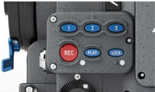
Fig. 36: Operator UI
15.3 EVF Controls
The EVF controls are located on the electronic viewfinder. They consist of a number of function buttons and a jogwheel.
| CAM Press the CAM button to open the EVF's CAM menu. | |
| EVF Press the E | VF button to open the EVF's EVF menu. |
| ZOOM Press the | ZOOM button for a temporary zoom-in to quickly check focus. Being zoomed in is indicated by an orange frame around the image. Frame lines are deactivated while zoom is active. |
| EXP Press the E | XP button (EXP = EXPOSURE) to toggle false color display on and off. |
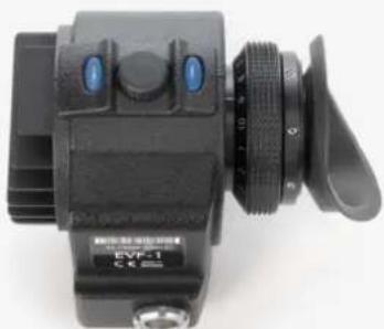
natural_image
Close-up of a black EVF-1 camera with lens and control buttons (no visible text or symbols on body)Fig. 37: EVF-1 left side
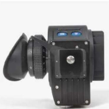
natural_image
Close-up of a black camera with lens and control panel (no visible text or symbols)Fig. 38: EVF-1 right side
When the LOCK button on the main controls is engaged, the CAM and EVF buttons are locked with the main controls and operator controls. The ZOOM and EXP buttons are not affected by the lock.
The message "Button is locked!" is displayed in the EVF when the CAM or EVF button is pressed while the main controls are locked.
15.3.1 Viewfinder EVF menu
Press the EVF button to open the Viewfinder EVF menu in the EVF display and set the viewfinder parameters. Use the jogwheel on the EVF to select and set menu options. Press the EVF button to exit the Viewfinder EVF menu.
| Brightness Select to set the brightness of the EVF from 1 (least bright) to 5 (brightest). With an EVF-2 connected, the brightness is expressed in nits ( cd/m^2 ). | |
| Gamma Select to set the gamma characteristic (technically the Electro-Optical Transfer Function or EOTF) of the EVF-2.Gamma 2: Gamma characteristic optimized for EVF-2.EVF-1: Gamma characteristic similar to EVF-1Note: Only available with EVF-2 connected. | |
| Rotate image When mounting the EVF to the right side of the camera,the image can be flipped to orient the image correctly in the viewfinder. Affects only the EVF image, MON OUT and recording images are not rotated. | |
| Smooth mode Select to set smooth mode On or Off. With smooth mode on, the EVF image shutters less when panning.Note: Smooth mode is only possible with frame rates up to 30 fps and shutter angles of 180.0 or less. If smooth mode is switched on but not available, the camera issues a warning. | |
| Surround view Select to set | set surround view on the EVF On or Off. When set to on, the additional pixels outside the recorded image area on the ALEXA's A2X sensor are displayed, allowing the operator to see outside the recorded image and keep unwanted objects, such as microphone booms, out of the shot. To view only the recorded image, set surround view to off. Note: Only available in sensor mode LF 16:9 |
| Surround mask Select to adjust the surround mask settings. If surround view is set to On, the boundary between the recorded area and surround view will always be indicated to allow proper framing. Users can choose between: • Black line • Color line • Mask 25% • Mask 50% • Mask 100% | |
| Status info Select to set status info to On or Off. When set to On, camera shooting parameters are displayed across the top of the EVF's image, outside the active image area and camera status information is displayed across the bottom of the EVF's image, outside the active image area. | |
| Frame lines Select to set frame lines to On or Off. Frame lines are a reference for framing that typically consist of an image frame, a center mark and an aspect ratio reference. See the appendix for more information on the ALEXA frame line format. | |
| Select frame lines 1 Select to set the main frame lines template from those stored in the camera. | |
| Select frame lines 2 Select to set the secondary frame lines template from those stored in the camera. | |
| Center mark Select to set the center mark to Off, Small Dot, Medium Dot or Cross to aid in image framing. | |
| User rectangles Select to display up to two additional user-editable rectangles in the EVF image. | |
| Edit user rectangles Select to adjust the user rectangles. | |
| Frame lines color Select to set the color of the frame lines. | |
| Frame lines intensity Select to set the brightness of the frame lines. | |
15.3.2 Viewfinder CAM menu
Press the CAM button to open the Viewfinder CAM menu in the EVF display and set camera parameters. Use the jogwheel on the EVF to select and set menu options. Press the CAM button to exit the Viewfinder CAM menu.
| FPS Select to set | the sensor frame rate. Preconfigured and previously added user-defined values can be selected in the FPS list. |
| SHUTTER Select | to set the shutter angle. Preconfigured and previously added user-defined values can be selected in the Shutter list. |
| EI Select to set the exposure index. Settings from EI 160 to EI 3200 can be selected, in steps of 1/3 stop. | |
| WB Select to set | the white balance. Preconfigured and previously added user-defined values can be selected in the WB list. |
15.4 Web Remote
All ALEXA cameras contain a web server that can provide a user interface for remotely controlling the ALEXA.
Connecting to the Camera
The Web Remote can be accessed through an Ethernet connection from the camera's ETH port to a computer's Ethernet port, using the Bonjour protocol or by directly entering the camera's IP address. First, make sure on the camera that MENU>SYSTEM>NETWORK>Web remote ready-only is set to Off. If you want to prevent access to the Web Remote, set MENU>SYSTEM>NETWORK>Web remote ready-only to On. Then connect the cable. To use the Bonjour protocol, open the web browser on the computer and enter the address alexa####.local in the browser's address bar, with #### being the serial number of the camera. Alternatively, you can look up the camera's IP address (INFO > SYSTEM) and enter that in the browser's address bar.
16 Wireless Video
The HD video transmitter transmits the video signal of MON OUT 3 to a Wireless Video Receiver (WVR-1) or Transvideo Starlite ARRI-WVS monitor.
It can wirelessly transmit at 5 GHz up to a distance of 600m with less than 1 ms delay. The transmission is always secured by 128 bit AES encryption and is uncompressed.
The camera can transmit to up to four receivers simultaneously.
NOTICE
The WVS is not compatible with any other wireless video transmission system.
Only devices with the same region setting are compatible with each other.
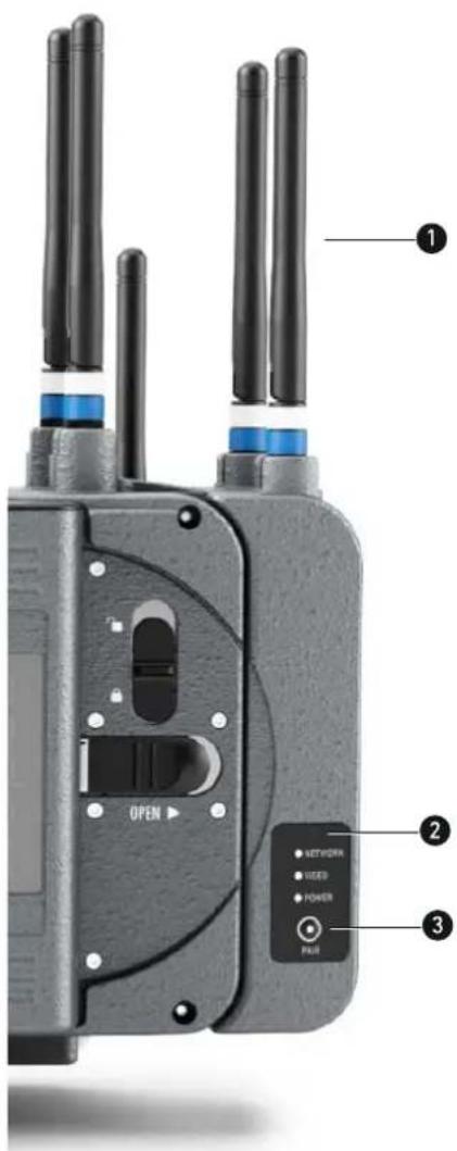
1 Wireless video antennas
2 Status LEDs: Network, Video, Power
3 PAIR button
16.1 Setting the region of the wireless video function
Setting the region of the wireless video module can only be done by ARRI Service Centers. Please note that only devices with the same region setting are compatible with each other.
CAUTION!
Wireless region settings specify where the wireless function can be used in compliance with local regulations. It may be illegal to use the wireless function in a region other than specified in the setting. Please ensure that the region is configured correctly, e.g. when traveling.
16.2 Preparation
1 Screw on two antennas on top of the HD video transmitter to the antenna connectors.
2 Attach a battery to the battery adapter on the back of the camera or use a power supply to power the camera.
3 Turn on the HD video transmitter in the camera menu and pair it to one or more receivers.
16.3 Status LEDs
| LED Status | |
| Signal | LOW = low link signal strengthMID = medium link signal strengthHIGH = high link signal strength |
| Network | Solid: Connection is establishedSlow blinking: Pairing activeFast blinking: System error |
| Video | Solid: Video signal is lockedFast blinking: System error |
| Power Shows if wireless video transmitter is powered | |
16.4 Pairing camera and receivers
To transmit video content from the camera to a WVR-1 or Transvideo Starlite ARRI-WVS, it is necessary to pair the devices. Pairing describes the function of connecting a transmitter to one or more receivers. The pairing needs to be confirmed at both devices with the push of the PAIR button. The pairing process is accompanied by a specific pattern of indicators through LEDs blinking on the devices.
Precondition:
▶ Select MENU > MONITORING > MON OUT 3 / WIRELESS VIDEO and ensure that Wireless video power is set to On.
MENU>MONITORING
| Electronic viewfinder | > |
| MON OUT 1 | > |
| MON OUT 2 | > |
| MON OUT 3 / Wireless video | > |
| Master magnification | 100% |
| Frame lines | > |
MENU>MONITORING>MON OUT 3
| Wireless video power | Off | |
| Frame rate | 23.976 | On |
| Format | 422 1.5G SL | |
| Scan format | p | |
| Surround view | On | |
| Frame lines + status info | > | |
Pairing:
- Make sure the transmitter and receivers you want to pair are at least 1 m apart.
- Turn on WVR-1. Make sure no other transmitters and receivers are powered up.
- Press PAIR on WVR-1 until NETWORK LED blinks fast.
- Press PAIR on the camera until NETWORK LED blinks fast.
- Pairing is complete when NETWORK LEDs turn to solid.
- Repeat the procedure for each additional WVR-1.
During the pairing process, the external monitor to which the WVR-1 is connected should show the following information:
1 "Registration in Progress"
2 "Searching for Camera Unit ..."
For instructions on pairing the camera with a Transvideo Starlite ARRI-WVS, please see the manual of the Transvideo Starlite ARRI-WVS.
NOTICE
If four receivers are paired to a transmitter, and another receiver is paired, the first of the already paired receivers will be unpaired and the new one will be added. The adding of new receivers works in a cyclic first-in first-out order.
An inactive receiver stays paired to the transmitter. If a fifth receiver is added to a setup with one inactive and three active receivers, the new receiver does NOT replace the inactive one. In this case, there is no differentiation between active and inactive devices. The rule mentioned above still applies.
NOTICE
Before pairing two devices, make sure that there is at least 1 meter / 3.3 feet distance between the devices.
16.5 Supported resolutions
| 1080p 23.976, 24, 25, 29.97, 30, 50, 59.94, 60 | |
| 1080psf | 23.976 (displayed as 1080i48)24 (displayed as 1080i48)25 (displayed as 1080i50)29.97 (displayed as 1080i60)30 (displayed as 1080i60) |
16.6 Sample setups
The number of WVS systems that can be used in parallel depends on the number of channels available, which is different for each region, and the radio noise present. In general, four to six systems can work in parallel.
It is possible to pair one ALEXA LF with up to four receivers (either the WVR-1 or the Transvideo Starlite ARRI-WVS). See an example setup below.
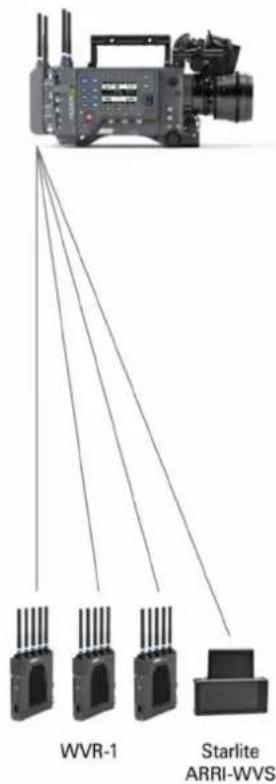
NOTICE
It is not possible to pair one WVR-1 with more than one ALEXA LF.
16.7 Software update
To up- or downgrade the HD wireless video module, it is necessary to connect it via USB to a Windows computer that runs the ARRI Wireless Video software, which is available for download on the ARRI web page. You need to have the current firmware installation file available to perform the upgrade. The user software guides you through the process of up- or downgrading.
NOTICE
The firmware up-/downgrade process of the wireless video module is separate from the regular ALEXA Software Update Packet (SUP) updates.

CAUTION!
Do not switch off power and do not remove the USB cable during the update, as this may damage the wireless video module.
17 Operation of the Camera
This chapter covers tasks the user will encounter while using the ALEXA. While previous chapters contained specific procedures for basic use, this chapter will outline broader tasks and offer recommendations and best practices, including camera configuration.
17.1 Internal recording
This chapter contains information and recommendations for internal recording. The user is encouraged to adapt the recommendations and workflow to individual and production needs.
NOTICE
- ARRI cannot be held responsible for the loss of any data in conjunction with internal recording.
- While we do everything we can to assure reliable functioning of different recording medias such as SXR Capture Drives, and while the mean time before failure (mtbf) for drives is excellent, a failure that results in loss of data may occur at any time. Therefore, you are obliged to implement and maintain at any time adequate and necessary data security measures and back up drive content as soon as possible. ARRI assumes or accepts no liability or responsibility for data loss or data corruption, or any other damages, loss or harm due to malfunction of recording drives.
17.1.1 Recording Module
The ALEXA LF uses SXR Capture Drives and Sony SxS PRO+ cards for internal recording. All media require an adapter specific to their type: SXR Capture Drives require the SXR Adapter, SxS PRO+ cards require the SxS Adapter 2. SxS PRO+ cards do not allow recording ARRIRAW data.
File System
Depending on the recording format, SXR Capture Drives are initialized with different file systems. SXR Capture Drives can be formatted in-camera or using Codex Software (Mac only) in a Codex Single Dock, or the standalone Codex Vault.
When the camera is set to ARRIRAW recording, SXR Capture Drives are initialized as Codex volumes. When the camera is set to ProRes recording, SXR Capture Drives are initialized with the UDF file system. In both cases, the file system is read-only for computers.
SxS PRO+ cards can only be used for ProRes recording. These cards are always initialized with the UDF file system and have to be formatted in the camera with the SxS Adapter 2.
17.1.2 Internal Recording Formats
ALEXA footage can be captured as QuickTime movies using an Apple ProRes ^™ codec or as unencrypted and uncompressed ARRIRAW file sequences.
NOTICE
Recording ARRIRAW internally works only with SXR Capture Drives.
ProRes
Recording in ProRes is a cost-efficient alternative to shooting ARRIRAW, as it requires less storage space and no further processing in post.
The following resolutions are available with ProRes recording:
| Sensor Mode Resolution | |
| LF 16:9 | HD (1920 x 1080) |
| 2K (2048 x 1152) | |
| 4K UHD (3840 x 2160) | |
| LF 2.39:1 4.5K (4448 x 1856) | |
| LF Open Gate 4.5K (4448 x 3096) |
ProRes RAID - Redundant Recording on SXR Capture Drives
In the ALEXA LF, ProRes is always recorded with a method (RAID) that provides redundancy for greater data security for SXR Capture Drives. As with ALEXA XT and SXT cameras, half the Capture Drive's capacity can be used to record ProRes, but the other half can be used to increase the safety of the recorded data.
ProRes RAID for SXR Capture Drives
When SXR Capture Drives are being formatted for ProRes in the ALEXA LF, a combination of RAID 1 (mirroring) and RAID 0 (striping) is used, commonly referred to as RAID 10. Drives zero and one will be combined into one RAID 1 volume and drives two and three into another. This provides redundancy. The resulting two RAID 1 volumes are combined into one RAID 0 volume so it can be accessed as one volume.
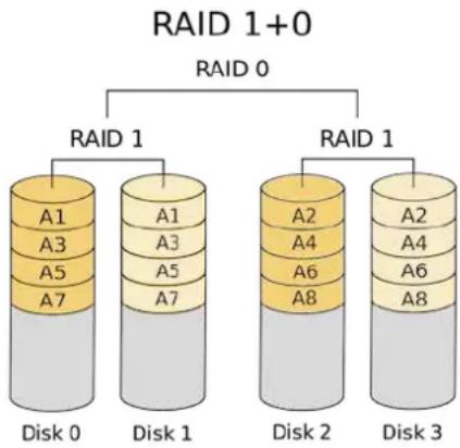
flowchart
graph TD
    A["RAID 1+0"] --> B["RAID 0"]
    B --> C1["RAID 1"]
    C1 --> D1["A1"]
    C1 --> D2["A3"]
    C1 --> D3["A5"]
    C1 --> D4["A7"]
    C1 --> D5["A1"]
    C1 --> D6["A3"]
    C1 --> D7["A5"]
    C1 --> D8["A7"]
    C1 --> D9["A8"]
    A --> E["RAID 1"]
    E --> F1["A2"]
    E --> F2["A4"]
    E --> F3["A6"]
    E --> F4["A8"]
    E --> F5["A2"]
    E --> F6["A4"]
    E --> F7["A6"]
    E --> F8["A8"]
    E --> G["Disk 0"]
    E --> H["Disk 1"]
    E --> I["Disk 2"]
    E --> J["Disk 3"]
Downloading ProRes RAID Data
SXR Capture Drives recorded in ALEXA LF require Codex Production Suite 4.1 or later for downloading. Codex Production Suite 4.1 or later is included in new SXR Capture Drive Docks, or available free of charge for owners of older docks.
To download ProRes from SXR Capture Drives recorded in ALEXA LF, the ARRI RAID driver must be installed in the downloading Mac. The ARRI RAID driver is included in Codex Production Suite 4.1, but will not be installed by default. To install, check the "Capture Drive RAID support" box when installing the Codex Production Suite.
The ARRI RAID driver has been tested with Mac OS 10.10 und 10.11.
NOTICE
CAUTION! RAID redundancy is very helpful if data from one of the two internal drives is corrupted or one of the internal drives is damaged. But the SXR Capture Drive still appears as one volume, and if it gets erased accidentally by the user, the data is gone.
CAUTION! While this redundancy is a great new feature, it creates some incompatibilities you should be aware of:
- If an SXR Capture Drive that has been formatted on an ALEXA LF should be downloaded on a Mac that does not have the ARRI RAID driver installed, the Mac cannot recognize the RAID formatted drive and will ask if this drive should be formatted. Don't format the drive, but install the ARRI RAID driver and try again.
- Please note that due to the camera's write pattern, there may be gaps in the clips which do not contain valid QuickTime data. These gaps may not be bit-identical on the individual SSDs unless the drives have previously been secure erased using the Codex Vault. This is normal and only relevant in cases where the date has to be restored manually.
Note: When working with ProRes clips without audio, Final Cut Pro 7 may fail during a Consolidate action as it does not recognize the file type correctly. To fix this problem, use the SetFile command line tool on all affected clips as follows: "SetFile -t MooV
ARRIRAW
ARRIRAW data delivers unencrypted, uncompressed and uncompromised image quality from an ALEXA camera. It offers the highest achievable resolution, the camera's natural color response and great exposure latitude as uncompressed and unprocessed sensor data. ARRIRAW images have only one channel. A color reconstruction algorithm calculates the missing components of each pixel based on the type and position of the array of colored filters (Bayer pattern) on the camera sensor.
ARRIRAW de-bayering is available through the ARRIRAW Converter (ARC) or custom processing, which is implemented in most of the major post production tools for dailies processing and mastering.
The following resolutions are available with ARRIRAW recording:
| Sensor Mode Resolution | |
| LF 16:9 4K UHD (3840 x 2160) | |
| LF 2.39:1 4.5K (4448 x 1856) | |
| LF Open Gate 4.5K (4448 x 3096) |
The camera will automatically calculate a CRC32C checksum for the image data inside each ARRIRAW frame. This checksum is recorded onto the SXR Capture Drive where Codex software uses it to verify the image content during all copying and processing steps. In addition to providing extra security, this also speeds up the copying process.
The checksum is also stored in the ARRIRAW header as metadata (fields 'ImageDataChecksumType' and 'ImageDataChecksum'), making it thus available to third parties. Note that this checksum does not validate the entire .ari file, only the image data itself.
Choosing a Recording Format
The selection of the recording format is a crucial decision which needs to be discussed with the production company and post production. While lower bit rate codecs offer longer recording times, they introduce compression artifacts that can limit creative choices.
| ProRes 422 Use for basic television production. Limited options in color correction. |
| ProRes 422 HQ Use for high quality TV production. Suitable for creative color correction. |
| ProRes 4444 Use for high quality TV and cinema production. Very suitable for creative color correction and visual effects work such as pulling mattes. |
| ProRes 4444 XQ The ideal choice for productions that are shooting for premium image quality, are looking for extreme color grading and want to preserve the superior tonal range of ALEXA's Log C signal. |
| ARRIRAW Use for cinema production, visual effects and high quality TV. Best format for creative color correction and visual effects work. Unencrypted and uncompressed format. Raw data needs to be processed into color images. |
Always test the full workflow pipeline with the preferred recording format before shooting.
Media preparation
The typical usage cycle of recording media is:
1 Format
2 Record
3 Copy
4 Back up
5 Verify data
6 Format
| Format Before recording, the drives/cards must be formatted. The camera always performs a blank format, which means that the media contain no metadata and are not assigned a reel number prior to recording the first clip. The camera auto-detects media with an invalid file system and asks the user to format the media. The ALEXA uses the UDF file system for ProRes recording and the Codex file system for ARRIRAW recording. Both file systems are read-only for computer systems, which minimizes the risk of data corruption. |
| Record When the REC button is pressed, the camera starts to write a clip to the media. With the first clip, the camera also assigns a reel number. There is more information on file naming later in this chapter. |
| Copy After recording is finished, the footage needs to be copied to another device in order to free up the media. The copy process should be verified using checksum calculation to ensure that no errors have occurred. |
| Backup The footage should ideally be copied to two physically separate destinations. The first copy should be the "working copy", and the second copy should be the "backup copy". These tasks can be done in parallel, as long as the end result is verified data on two independent devices. |
| Format Only when the data has been copied to two independent devices and verified, should the drive/card be formatted to clear all data. We recommend that the person who verifies the primary and back-up copies should also format the media. The camera crew then always receives an empty card and does not need to worry if the footage has already been copied from the drive/card. SxS cards can be formatted with any file system, as they have to be reformatted by the camera anyway. SXR Capture Drives can be formatted with the Codex software and do not require to be reformatted in the camera. |
NOTICE
SxS PRO+ cards currently cannot be formatted on Mac OS X 10.11 (El Capitan) using the Disk Utility. To format these media, open the Terminal and enter the following command:
diskutil eraseVolume HFS+ empty /Volumes/A001R1FM/,
where A001R1FM needs to be replaced with the name of your card.
File Structure for ProRes Recording
After an SxS PRO+ card or SXR Capture Drive is formatted for ProRes recording in the camera, it is named ARRI_UDF until the first clip is recorded. Once a clip has been recorded, the name changes to the camera index letter and current reel number, which can be preset in the PROJECT menu. Clips are stored in a folder with the same name as the media.
In addition to the clips, recording writes an XML file and an ALE file.
The XML file is a Final Cut Pro 7 (FCP) XML file. When opened in Final Cut Pro 7, all clips are imported as one bin. If the clips are copied from the card to another destination, the file paths in the XML file have to be adjusted to match the new file location. The XML file is not compatible with FCP X.
The ALE file is an Avid Log Exchange file for Media Composer. It contains all static clip metadata, which is also embedded in each recorded clip.
For more information about ALEXA metadata, please refer to the ALEXA Metadata white paper, available at http://www.arri.com/camera/digital_cameras/downloads in the "Technical Information" section.
File Structure for ARRIRAW Recording (Codex VFS)
When an SXR Capture Drive with ARRIRAW footage is loaded on a computer, it shows up like a regular external drive. Operating underneath, however, is the Codex Virtual File System (VFS). The VFS can present, for example, readily processed DPX files, MXF/DNxHD and/or QuickTime/ProRes proxies next to the original ARI files on the Codex volume. Except for the recorded data on the drive, none of these additional files actually exist. It's only when these files are requested, that they are generated, on-demand, and on the fly. Hence the term "virtual".
The file formats, file naming and directory structure that will be presented by the VFS are fully configurable through the Codex Platform software. This makes the VFS a highly flexible tool for providing exactly the material you require, when you want it, without redundant processing and storage overhead on your drives.
The default VFS configuration for the output of only ARRIRAW files uses the following file path:
For detailed instructions on the Virtual File System configuration, please visit http://www.codexdigital.com/support/media-stations and download the Codex VFS Guide.
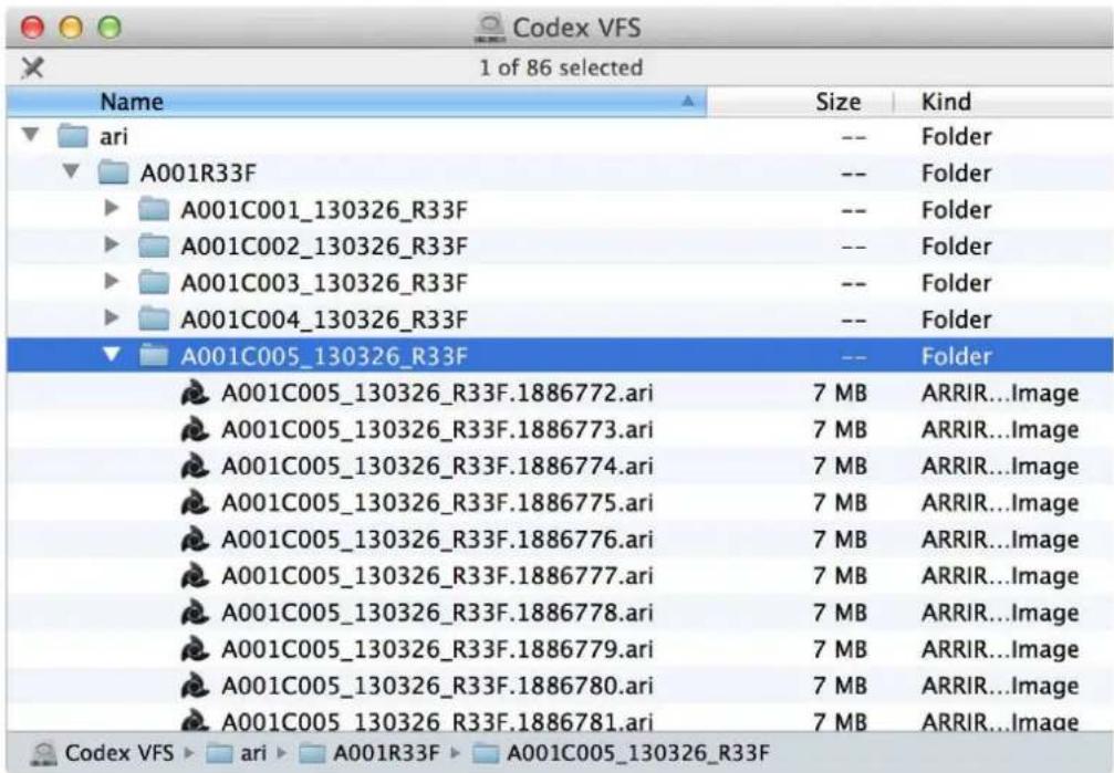
Fig. 39: Example of an SXR Capture Drive using the VFS default file structure in Mac OS X
File naming scheme
The ALEXA automatically names files as they are created on the recording media. While it is possible to change the file names later on a computer, it is not recommended, as the ALEXA naming scheme has been developed to minimize the risk of duplicate file names.
The file name consists of five parts:
- Camera Index: One character, A-Z. User assignable, should match the camera unit. For example, the camera index A can be assigned to the A camera, and B to the B camera.
- Reel Counter: 3 characters, 001-999. Auto-assigned to each drive/card, automatically advanced by one for each new drive/card. The user can change the counter for the next reel. This should only be done under special circumstances, such as after changing the camera body in the middle of a shoot.
- Clip Index: One character, fixed to C. Main use is to separate the reel counter from the clip counter. If more than 999 clips are recorded to one card (not likely to happen), it changes to D.
- Date: Current date, in order YYMMDD, as set in Menu>System/Time/Date, separated from the other naming components by underscores.
- Camera ID: Consists of a one letter prefix, currently fixed to R, and the camera serial number encoded in 3 letters Base36 (0-9, A-Z).
The file name for ARRIRAW files on SXR Capture Drives is controlled by the VFS configuration. We highly recommend to use the standard file naming convention "
The reel counter should be set to 001 at the beginning of a shoot. The camera will then automatically advance the reel number each time a new drive/card is loaded into the camera, formatted and recorded on. If a previously recorded drive/card is reloaded in the camera (comparable to a short end of a film roll), it will keep its reel number and the camera will continue the reel count. If the drive/card is loaded in another camera, the card keeps its name, but a new folder with the according camera ID and reel number is created in the root folder of the drive/card. It is possible, but usually not necessary, to manually change the next reel number in the Project menu.
Examples
A typical ProRes/Quicktime file name would look like this:
• A004C010_180208_R18T.mov
A typical ARRIRAW file name would look like this:
• A004C010_180208_R18T.1886777.ari
The translation of this name is as follows:
• This clip was the tenth clip recorded on the fourth reel.
• This clip was recorded on February 08, 2018.
- The camera assigned the Base 36 serial number 18T, which translates into the decimal serial number 1613
- Frame number 1886777 on a 24 fps project translates to a time of day time code of 9:50:15pm and 17 frames.
Additional recommendations
To minimize the risk of lost data, ARRI suggests the following guidelines for data management:
- Pre-format your media. Format all the drives/cards in the camera before shooting begins. This will save production time at least until all cards have been used once. The media do not receive a reel number until the first clip is recorded, so there is no need to use the cards in the same order they were pre-formatted.
- Limit the recording time, especially on the drives. Compressed recording offers very long recording times. Please consider limiting the recording time to 30 minutes of footage per card/drive to reduce risk of loosing data.
- Download and back up data immediately after reloading the camera to minimize the time that data exists in just one place.
- On SxS cards, use the write protect tab before sending it to the data wrangler.
- After an SxS card has been downloaded and backed up, disengage its write protect before formatting.
Metadata
Metadata is stored in a Final Cut XML file, an Avid ALE file, in the recorded frames/clips and embedded in the HD-SDI signals. The most important metadata for post production workflow is the tape name, as it will be one of the primary identifiers used in the EDL. The term tape name is an existing post-production naming convention that is also used for nonlinear media. The terms tape name and reel name may be used interchangeably.
The tape name of ALEXA files is limited to 8 letters to match the CMX 3600 EDL standard. It consists of the Camera Index, reel counter and the Camera ID. Based on the previous example, the tape name of the clip would be A004R18T.
Even if the user forgets to assign different camera indices to two cameras on the same project, the Camera ID metadata guarantees unique tape names.
The Quicktime file carries a single timecode track.
For more information about ALEXA metadata, please refer to the ALEXA Metadata white paper, available at http://www.arri.com/camera/digital_cameras/downloads in the "Technical Information" section.
17.2 Monitoring
The ALEXA's monitoring options are the electronic viewfinder EVF and the MON OUT. Surround View is available on both while the camera is in LF 16:9 sensor mode. When set to on, the additional pixels outside the recorded image area on the ALEXA's A2X sensor are displayed, allowing the operator to see outside the recorded image and keep unwanted objects, such as microphone booms, out of the shot. To view only the recorded image, set surround view to off.
To aid in framing, both the EVF and MON OUT can display frame lines overlaid on the image. Frame lines can be considered electronic versions of ground glass markings in film cameras.
17.2.1 Frame Lines
A standard set of frame lines for different aspect ratios is provided in the camera, including:
Sensor mode LF 16:9
• 1.78:1 (ARRI 1.78)
• 1.78:1 for HD cropping (ARRI 1.78 HD)
• 1.85:1 (ARRI 1.85)
• 1.85:1 for 2K DCI-compatible cropping (ARRI 1.85 2K DCI)
• 2.00:1 (ARRI 2.00)
• 2.39:1 (ARRI 2.39)
• 2.39:1 for 2K DCI-compatible cropping (ARRI 2.39 2K DCI) *
• Super 35 6:5 (ARRI S35 6x5 2.6K Scope 2x)
• Super 35 16:9 (ARRI S35 16x9 2.8K)
• Super 35 16:9 (ARRI S35 16x9 3.2K)
* available with 2K recording resolution
Sensor mode LF 2.39:1
• 1.78:1 (ARRI 1.78)
• 1.85:1 (ARRI 1.85)
• 2.00:1 (ARRI 2.00)
• 2.39:1 (ARRI 2.39)
• 2.39:1 for 4K DCI-compatible cropping (ARRI 2.39 4K DCI)
• Super 35 16:9 (ARRI S35 16x9 2.8K)
• Super 35 16:9 (ARRI S35 16x9 3.2K)
Sensor mode LF Open Gate
• 1.78:1 (ARRI 1.78)
• 1.78:1 for UHD cropping (ARRI 1.78 UHD)
• 1.85:1 (ARRI 1.85)
• 1.85:1 for 4K DCI-compatible cropping (ARRI 1.85 4K DCI)
• 2.00:1 (ARRI 2.00)
• 2.39:1 (ARRI 2.39)
• 2.39:1 for 4K DCI-compatible cropping (ARRI 2.39 4K DCI)
• Super 35 3:2 (ARRI S35 3x2 3.4K)
• Super 35 6:5 (ARRI S35 6x5 2.6K Scope 2x)
• Super 35 16:9 (ARRI S35 16x9 2.8K)
• Super 35 16:9 (ARRI S35 16x9 3.2K)
Frame lines starting with "ARRI S35" mark the corresponding sensor area of a Super 35 ALEXA when using standard PL mount lenses with the PL-to-FPL adapter.
To create custom frame lines, use the Frame Line Composer on the ARRI website. Save the new frame lines as XML files to an SD card formatted on the ALEXA, in the Frame lines folder. The ALEXA supports up to 16 frame line templates.
17.2.2 Status Info Overlays
The ALEXA can display camera status information on EVF and MON OUT.
At the top and bottom of the screen, the ALEXA displays textual status information. The top status bar consists of sensor FPS, shutter angle, exposure index and white balance. In the EVF, the status bar also works as a menu, allowing the user to change the values when the CAM button is pressed.
The bottom status bar displays information about the battery levels, recording/standby flag and remaining capacity of internal storage.
NOTICE
The maximum size of a single clip is limited to about 229 GB. Therefore, the camera shows the remaining time for both the whole media as well as the current clip as soon as recording starts. When the remaining time reaches zero, the camera will stop recording similar to a full medium. During standby, the camera shows only the remaining time for the whole media.
On the left and right of the screen, icons provide information about the current status of the camera. The icons are organized into groups.
The left icon group is labeled SYS and contains information about the general system state of the ALEXA. On the right side, there are three groups labeled MON, EVF and LOOK. They provide specific information about MON OUT 1/2/3, EVF and the application of ARRI Look File 2 files.
The status icons that belong to the respective output path are as bright as the rest of the status info, while the icons of the other paths are dimmed. This makes it easier to distinguish to which monitoring output a monitor is connected to.
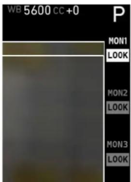
Fig. 40: Status overlays on MON OUT 1
The following table explains the icons in the SYS group:
 | Indicates that the current recording mode is set to ProRes. |
 | Indicates that the current recording mode is set to AR-RIRAW. |
 | Indicates that the processing of the recording is set to Log C. |
 | Indicates that the processing of the recording is set to ARRI Look File 2 file. |
 | Indicates that the current recording resolution is set to HD. |
 | Indicates that the current recording resolution is set to 2K Cine. |
 | Indicates that the current recording resolution is set to 4K UHD. |
 | Indicates that the current recording resolution is set to 4.5K. |
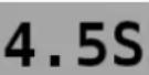 | Indicates that the current recording resolution is set to 4.5K in 2.39:1 (Scope). |
| Indicates that there is a warning condition in the camera. | |
| Warns that the camera has detected an error. | |
| Indicates that the camera temperature is outside of its optimal range. | |
| Warns that the camera temperature has reached a critical point where it can no longer be operated and must be powered down. | |
| Indicates that audio recording has been switched on. | |
 | Warns that audio recording has been switched on, but is currently disabled, e.g. because of an off-speed framerate. |
 | Indicates that the camera controls are locked.Only shown in EVF |
 | Indicates that a frame grab is currently in progress. |
 | Indicates that the signal from the RET IN connector is currently being displayed. |
The following table explains the icons in the MON and EVF group on the right:
| Icon Description | |
 | Indicates that the processing of the respective output is set to Log C. |
 | Indicates that the processing of the respective output is set to ARRI Look File 2 file. |
 | Indicates that the processing of the respective output is set to ALEXA Classic 709. |
 | Warns that peaking is active on the respective output. |
 | Warns that smooth mode is active in the EVF. |
17.3 Using Timecode
Timecode ensures that every image of recorded media can be identified with a unique value and synced with corresponding media, such as sound or the second camera in a 3D application. When used with other metadata, such as reel names, all recorded media maintains its unique identity.
Following are two ways timecode can be used on a production:
External TC, Time of day
- Use: This format is often used on multi-camera productions with sync-sound. When all cameras are running at sync-sound speed, which is also the project frame rate, sound and image time code match and allow for easy syncing in post.
- Setup: The sound department acts as the timecode master, and generates timecode which uses the time of day as a value, and a time base matching the project frame rate. Twenty-four hours of time will translate into twenty-four hours of time code.
Timecode is fed to the camera via the TC connector. The timecode source must be set in the camera to Ext LTC and the mode to Free Run. The project fps setting must match both the sensor frame rate and the time base of the external timecode signal. The camera can be set to use Jam sync generator, in which it samples the timecode value once and then continues counting based on its own high-precision crystal clock. The timecode source can be disconnected from the camera after jamming in Jam sync generator mode. This mode ensures stable timecode with an offset of less than one frame for each eight hours, after which the camera has to be re-jammed.
Alternatively, the camera can be set to regenerate mode, or Regen on the TIMECODE OPTIONS screen. In Regen mode, the camera uses the timecode value of the external timecode source. This ensures correct timecode for an infinite duration, but the timecode source must remain connected to the camera. Note that the camera ignores external timecode during record and counts using its internal clock to avoid timecode jumps should connection problems arise, e. g. due to a faulty timecode cable.
- Variations: If shooting starts close to midnight, the timecode might be started with an offset time of day to prevent a rollover at midnight.
- Restrictions: External timecode is only possible if the camera is running at sync-sound speed. If the camera is over- or under-cranking, the timecode frame rate will no longer match the sensor framerate, and timecode values would either be duplicate or dropped. To prevent this, the ALEXA will automatically switch to Int TC source and Regen mode when the sensor frame rate is changed.
Internal TC, Rec Run
- Use: Record run timecode is often used on single camera productions that are either MOS or use a dumb slate to sync picture and sound. Record run timecode guarantees continuous timecode on all recorded data. Record runtime code also works with over- and under-cranking.
- Setup: The timecode source must be set to Int TC, the mode to Rec Run and the generator to Regen. Timecode counts up only during recording, by one frame for each image generated by the sensor. The timecode counts at the project frame rate set on the camera. Normally, the timecode hour value advances by one hour for each new reel, using only hours 01-20 for reel 1-20, and then restarting at hour 01 for reel 21.
- Variations: Record run timecode might be used for off-speed work on productions that use external timecode sources for all sync sound.
- Restrictions: None.
17.4 Syncing the Sensors of Two Cameras
Two ALEXAs can be synced for 3D applications or any application requiring sensor sync using the EXT connectors and corresponding cable. When synced, images are captured from each camera's sensor at precisely the same time.
NOTICE
- Syncing two sensors is possible at frame rates of at least 1.000 fps.
- Use both sensor sync and settings sync (see next chapter) in 3D setups.
To sync the sensors of two ALEXAs:
- Connect an EXT cable KC 155-S to the EXT ports on each ALEXA.
- In the System menu on the master camera, select External Sync.
- On the EXT SYNC screen, set Sensor sync to EXT master.
- In the System menu on the slave camera, select External Sync.
- On the EXT SYNC screen, set Sensor sync to EXT slave. It takes approximately five seconds for the two ALEXAs to sync.
The master camera triggers the slave camera so that images are created at the same moment of time with an accuracy of 10 s. Whenever an error occurs, the camera will issue a warning.
Image integration between master and slave camera has a locked offset of less than 10 s. This means that in the worst case, exposure differs by 4.3% (@ 60 fps frame rate and 5.0° shutter angle). With a regular exposure time (24 fps, 172.8°), the maximum difference is 0.05%.
Synchronizing Image Output
The MON OUTs of two ALEXAs can also be synchronized. To achieve this, the user must send a trigger from the master camera to the slave camera after sensor sync is established.
To sync the MON OUTs of two ALEXAs:
- Ensure that the sensors of the two ALEXAs are synced.
- Ensure that MON OUT fps equals sensor fps.
- In the System menu on the master camera, select External Sync.
- On the EXT SYNC screen, select Send HD sync trigger.
- Press the jogwheel to send the trigger to the slave camera.
The camera will display the message HD sync trigger sent to slave camera!. If the sensors are not synced, the camera will display the error message Trigger not sent. Camera must be set to Ext sync: Master!.
After the sync trigger has been sent, the slave camera will no longer display the warning HD outs not synced. Trigger now!.
If the two cameras' settings are synced over Ethernet, the trigger is automatically sent.
When the outputs are synced, jitter between the two cameras' HD outputs is less than 500 ns. The HD output of each camera can be advanced or delayed by up to 30 HD clocks (1 HD clock=13.46 ns), allowing for a total shift of 60 HD clocks (808 ns total) between cameras.
Timecode
Timecode is also transmitted from the master to the slave over the EXT cable. When a camera has been set to slave, it automatically uses the timecode values transmitted over the EXT cable. The TC screen will display EXT TC from master camera as TC source, and all options are disabled. Only the master camera outputs LTC timecode on its TC connector.
NOTICE
- In a setup with sensor sync, but without settings sync, recording needs to be started first on the slave camera, and then on the master camera.
- When the mirror shutter is switched on, an ALEXA Studio can only be synced to another ALEXA Studio.
- Recording on the slave camera may stop a few frames later than on the master camera. Sync up the clips by timecode to ensure matching master/slave footage.
17.5 Syncing the Settings of Two Cameras
Two ALEXAs can be operated with synchronized settings.
Camera connection
The settings of two ALEXAs can be synchronized over Ethernet using the ALEXA Ethernet/Ethernet Cable KC 156-S, or over an ethernet hub using the ALEXA Ethernet/RJ-45 Cable KC 153-S.
Camera setup
To sync the settings of two ALEXAs over Ethernet:
- Connect an ALEXA Ethernet/Ethernet Cable KC 156-S to the EXT ports on both ALEXAs, or an ALEXA Ethernet/RJ-45 Cable KC 153-S to the ethernet hub and the EXT port of each ALEXA.
- In the System menu on the master camera, select External Sync.
- On the EXT SYNC screen, set Settings sync to ETH master.
- In the System menu on the slave camera, select External Sync.
- On the EXT SYNC screen, set Settings sync to ETH slave. The two ALEXAs will automatically negotiate IP addresses. It takes approximately five seconds to establish a connection.
The master camera will initially distribute its settings to the slave camera. Once this is done, settings can also be changed on the slave camera, and the change will take effect on both cameras. This is useful if the master camera's controls are not accessible.
If a camera is set to ETH master or ETH slave, but is not connected to another camera, a warning is displayed on the STATUS Info screen.
Synced settings
The following settings are synced when syncing two ALEXAs:
WB>White Balance + CC Tint
EI>Exposure Index
FPS>Sensor FPS
SHUTTER>Shutter Angle
COLOR>REC Processing
COLOR>MON OUT 1 Processing
COLOR>MON OUT 2 Processing
COLOR>MON OUT 3 Processing
MENU>Recording>Resolution
MENU>Monitoring>EVF>Surround view
MENU>Monitoring>EVF>Anamorphic desqueeze
MENU>Monitoring>MON OUT 1>Frame rate
MENU>Monitoring>MON OUT 1>Scan format
MENU>Monitoring>MON OUT 1>Status info
MENU>Monitoring>MON OUT 1>Surround view
MENU>Monitoring>MON OUT 1>Surround mask
MENU>Monitoring>MON OUT 1>Framelines
MENU>Monitoring>MON OUT 1>Anamorphic desqueeze
MENU>Monitoring>MON OUT 2>Frame rate
MENU>Monitoring>MON OUT 2>Scan format
MENU>Monitoring>MON OUT 2>Status info
MENU>Monitoring>MON OUT 2>Surround view
MENU>Monitoring>MON OUT 2>Surround mask
MENU>Monitoring>MON OUT 2>Framelines
MENU>Monitoring>MON OUT 2>Anamorphic desqueeze
MENU>Monitoring>MON OUT 3>Frame rate
MENU>Monitoring>MON OUT 3>Scan format
MENU>Monitoring>MON OUT 3>Status info
MENU>Monitoring>MON OUT 3>Surround view
MENU>Monitoring>MON OUT 3>Surround mask
MENU>Monitoring>MON OUT 3>Framelines
MENU>Monitoring>MON OUT 3>Anamorphic desqueeze
MENU>Project>Project fps
The slave camera also takes over the Camera ID of the master camera, so file names are identical except for the Camera ID prefix. It is important to give the master and the slave camera different Camera ID prefixes to prevent duplicate file names.
When formatting media in settings synchronized cameras, the next reel count of the master camera takes effect.
NOTICE
- An error will be triggered on pressing record when at least one of the synced cameras is not ready for recording (e.g. because of missing medium).
- Automatic white balance for synced cameras can only be initiated on the master camera.
- Sensor mode needs to be switched manually on all synced cameras. Do not start recording until all cameras have loaded the same sensor mode.
18 Remote Control Unit RCU-4
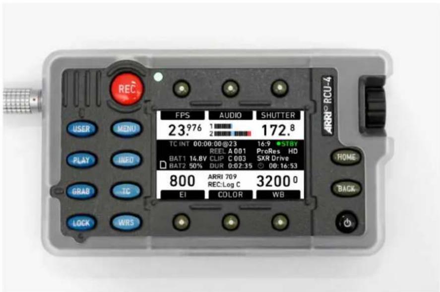
The camera can be remotely controlled with an RCU-4. This device mirrors the controls on the camera's right side. It is connected to the camera's Ethernet port. Power is supplied via the Ethernet cable.
To power the RCU-4, connect it to a camera, make sure the camera is powered up, and press the power button.
During boot-up, the RCU-4 compares its firmware version with the camera firmware version. If it detects a difference, it will update itself to match the camera's firmware version. When the update is completed, the RCU-4 will shut down automatically.
The power button of the RCU-4 only affects the RCU-4. It is not possible to power or to shut down the camera with the RCU-4. When the camera is powered down, the RCU-4 shuts down automatically as it loses its power supply.
The LOCK button of the RCU-4 locks only the RCU-4. It does not affect the camera lock.
For more information, please refer to the RCU-4 user manual.
19 Index
1
12 V 33
A
About This Manual....9
Appendix....149
ARRI Look File 2 files....69
AUDIO....63
AUDIO IN.... 32
AUDIO OUT 33
B
Basic precautions.... 45
BAT 31
BAT Connector.... 18
Bridge Plate adapter BPA-1 28
Bridge Plates BP-12/BP-13 27
C
Camera Controls....57
Camera Support 22
Center Camera Handle CCH-1 26
Cine-Style Block Batteries.... 19
COLOR....68
Condensation.... 16
Connector Pin Outs 152
Connectors.... 30
D
Dimensions and Weights.... 162
Disclaimer....7
Display....57
Display + Beeper.... 111
E
EI....66
Electronic Viewfinder 22,97
ETHERNET 32
EVF 32
EVF Controls 120
Explanation of Warning Signs and Indications.... 14
EXT 32
External Sync.... 109
F
False Color Display.... 157
False Color Index.... 104
Fan mode.... 113
Filter cleaning....55
Firmware - Software Update Packages (SUPs).... 115
FPS 62
Frame Lines.... 101, 136
Function Buttons....73
G
General Precautions.... 16
General Safety Guidelines.... 14
Gold Mount Batteries 20
H
Hand Units....92
HOME screen....58
1
Imaging.... 106
In-Camera Filter Module LF IFM 43
INFO 75
Internal recording.... 129
Internal Recording Formats.... 129
L
Layout of the ALEXA 12
Lens Motors....90
Lens Mounting.... 40
Lens Support....41
Levelling Block LB-1 28
LFFSND Filter Set (Full) 45
Lists and User Lists.... 61
LPL mount....40
M
Main Controls....57
Mains Unit NG 12/26 R.... 19
Maximum lens mounting depth for PL lenses.... 44
Menu....93
Minimum Equipment Recommended For Operation.... 22
Monitoring.... 96, 136
MON OUT 1/2/3.... 31, 99
Mounting in-camera filters....52
N
Network.... 113
0
Onboard Batteries 20
Operation of the Camera 129
Operator controls.... 119
P
PLAY 82
Plus Camera Controls 86
Power....109
Power Management 18
Power Outputs.... 21
Power Supply.... 18
Production Info.... 105
Project.... 104
R
Radio System....85
Recording....94
Recording Module.... 36, 129
Remote Control Unit RCU-4 145
Required shimming and maximum lens mounting depth.... 45
RET IN....31
RS....32
S
Safety Guidelines.... 14
Safety instructions for in-camera filtration.... 44
Scope.... 10
Screen Buttons....58
SD card.... 114
SD Card.... 33
Shimming the lens mount.... 46
Shoulder Pad SP-3.... 29
SHUTTER 66
Specific Safety Instructions.... 14
Status Info Overlays.... 137
Storage and Transport.... 16
Syncing the Sensors of Two Cameras.... 140
Syncing the Settings of Two Cameras.... 142
System....106
System Time + Date.... 112
T
TC.... 33,74
Technical data.... 149
Test Signal.... 110
TIMECODE OPTIONS....74
Tripod and Remote Heads.... 22
U
USER 78
User Pixel Masking.... 107
User Setups.... 117
Using Timecode.... 139
V
Viewfinder Cables 24
Viewfinder CAM menu 122
Viewfinder EVF menu.... 121
Viewfinder Mounting Bracket 24
V-Lock Batteries.... 20
W
Warning and Error Messages.... 158
WB....71
Web Remote 123
Wedge Adapter WA-1 and Quick-Release Plate QR-HD-1.... 28
WiFi....113
Wireless Remote System 85
20 Appendix
20.1 Technical data
Image Sensor
Type A2X CMOS sensor
Sensor frame rates 0.750 - 150.000 fps
(depending on sensor mode and recording format)
Shutter angle 5.0° - 358.0°
Active photo sites (incl. surround view) 4448 x 2502 (LF 16:9)
4448 x 1856 (LF 2.39:1)
4448 x 3096 (LF Open Gate)
Aperture of recorded image 31.68 x 17.82 mm (LF 16:9)
36.70 x 15.31 mm (LF 2.39:1)
36.70 x 25.54 (LF Open Gate)
Photo site pitch 8.25 μm
Aspect ratios 1.78:1 (16:9)
2.39:1
1.44:1 (Open Gate)
Filters optical low pass, UV, IR
Color filters RGB primary colors
Lens
Lens mount Exchangeable lens mount, with LPL
mount installed
Flange focal depth
44.00 mm nominal
Image processing
White balance
2000 - 11000 Kelvin
CC Shift
-12 to +12
EI rating
160 - 3200 ASA
Recorded image resolutions (pixels)
1920 x 1080 (LF 16:9 HD)
2048 x 1152 (LF 16:9 2K)
3840 x 2160 (LF 16:9 4K UHD)
3840 x 2160 (LF 16:9 ARRIRAW)
4448 x 1856 (LF 2.39:1)
4448 x 3096 (LF Open Gate)
Viewfinder EVF-1
Technology LCOS imaging device
Resolution 1280 x 784 pixels
Viewfinder EVF-2
Technology OLED imaging device
Resolution 1920 x 1080 pixels
Power
Power supply (BAT) DC 19.5 - 34 V
Power supply (onboard battery) DC 18.5 - 34 V
Power management Active ORing between BAT connector
and onboard battery adapters
Power consumption ca. 120 W (recording ProRes 4444 at
24 fps in LF 16:9 sensor mode onto an SxS PRO+ 256 GB card with EVF-1 and wireless video on but without accessories)
ca. 160 W (recording ARRIRAW at 90 fps in LF Open Gate sensor mode on-to an SXR Capture Drive 2 TB with EVF-1 and wireless video on but without accessories)
Power outputs 4 x RS (24 V), 1 x 12 V
Recording
Recording media Codex SXR Capture Drives
Sony SxS PRO+ 256 GB cards
Recording formats Apple QuickTime ProRes 422
Apple QuickTime ProRes 422 HQ
Apple QuickTime ProRes 4444
Apple QuickTime ProRes 4444 XQ
ARRIRAW (ari)
Image Outputs
Monitoring outputs EVF out: proprietary signal for EVF
with delay <1 frame
3x MON OUT:
422 1.5G @ frame rates:
23.976, 24, 25, 29.97 and 30 fps
422 6G @ frame rates (MON OUT
1/2):
23.976, 24, 25, 29.97 and 30 fps
Timecode
Type Tunable TC clock generator with crys-
tal oscillator
TC input LTC in
TC outputs LTC out
HD-SDI LTC/VITC out
Others
SD card most SD cards with FAT/FAT32 up to 4
GB
Sound level under 20 dB(A) @ 24 fps and ambient
temperature < 25°C / 77°F
Environmental -20°C to +45°C @ 95% relative hu-
midity max, non condensing
HD video transmitter
Power consumption 7W
Output resolution 1920 x 1080
Frame rates p: 23.98, 24, 25, 29.97, 30
psF: 23.98, 24, 25, 29.97, 30
Audio 2 channels, 48KHz PCM
embedded in HD-SDI signal
Transmission range 600m (2,000 ft) line of sight
Latency < 1ms
Encryption 128bit AES
Modulation process and other specifics OFDM (Orthogonal Frequency-Division
Multiplexing)
Bandwidth 40MHz
WiFi module
IEEE 802.11b: 1/2/5.5/11 Mbit/s
Modulation DSSS, Bandwidth: 22 MHz
IEEE 802.11g: 6/9/12/18/24/36/48/54
Modulation OFDM, Bandwidth: 20 MHz
Mbit/s
Dimensions and weight
For dimensions and weight, please refer to the dimensional drawings.
20.2 Connector Pin Outs
NOTICE
The drawings of the connectors are not to scale.
All pin-outs for camera interfaces appear as seen by the user.
BAT
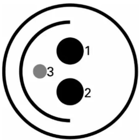
natural_image
Simple diagram of three black circles labeled 1, 2, and 3 inside a larger circle (no text or symbols beyond labels)1 GND
2+24V
3 BAT-COM
RS
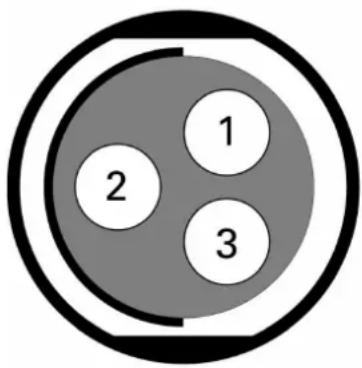
1 GND
2 24V-AUX
3 R/S
12V
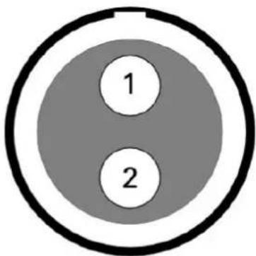
1 GND
2 12V-AUX
TC
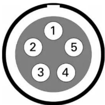
1 GND
2 LTC IN
3 ASCII
4 TUNE OUT
5 LTC OUT
EXT
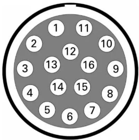
1 RS422-TXD(+)
2 RS232-TXD
3 CAN1-L
4 CAN1-H
5 CAN2-L
6 CAN2-H
7 24V-AUX
8 RS232-RXD
9 RS422-RXD(-)
10 RS422-RXD(+)
11 RS422-TXD(-)
12 GND
13 TTL-IN1
14 TTL-IN2
15 24V-AUX
16 GND
ETHERNET Camera Side
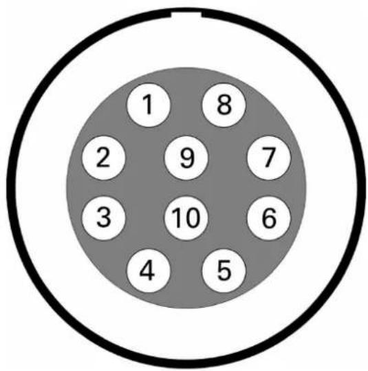
1 MX-1P CTS (white-orange)
2 MX-1N DTR (orange)
3 MX-2P GND (white-green)
4 MX-2N DCD (green)
5 MX-3P TXD (blue)
6 MX-3N RXD (white-blue)
7 MX-4P DSR (white-brown)
8 MX-4N RTS (brown)
9 GND
10 24V-ETH
ETHERNET PC Side
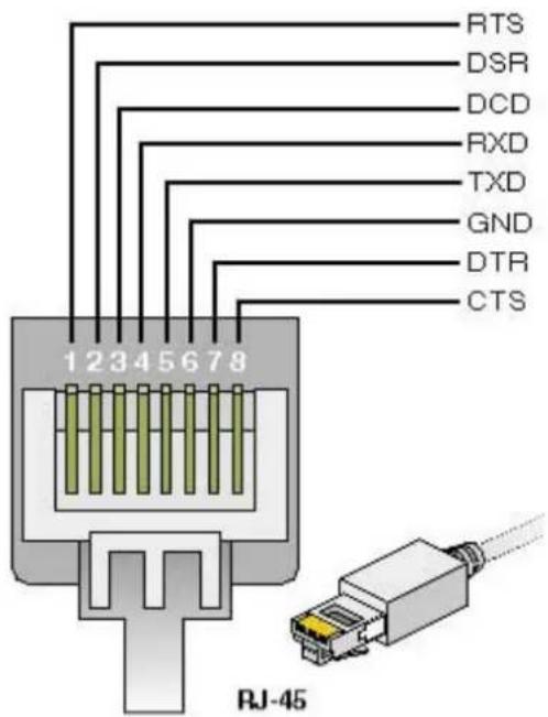
RTS brown
DSR white-brown
DCD green
RXD white-blue
TXD blue
GND white-green
DTR orange
CTS white-orange
AUDIO IN
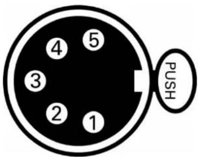
1 AGND
2 L-IN(+)
3 L-IN(-)
4 R-IN(+)
5 R-IN(-)
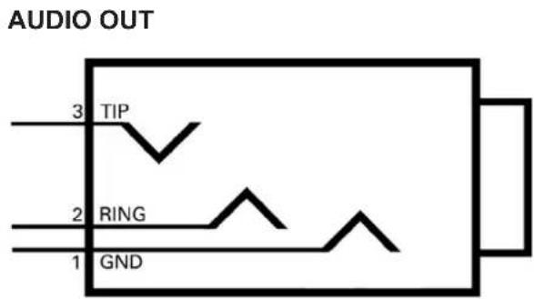
1 GND
2 R-OUT
3 L-OUT
20.3 False Color Display
The false color display is a tool to check correct exposure. It can be activated on EVF and MON OUT, and takes the respective gamma setting as a basis for calculation. When active, the image is turned into a greyscale image with important luminance ranges shown in signal colors. Note that the false color tool is only suitable for checking exposure and is not an appropriate tool for checking other image parameters or sensor quality.
Color Encoding
Six different colors are used to show the important luminance ranges.
| What | Signal Level | Color | |
| White clipping | 100% - 99% | red | |
| Just below white clipping | 99% - 97% | Yellow | |
| One stop over medium gray (Caucasian skin) | 56% - 52% | pink | |
| 18% medium gray | 42% - 38% | green | |
| Just above black clipping | 4.0% - 2.5% | blue | |
| Black clipping | 2.5% - 0.0% | purple | |
Fig. 41: False Color Encoding
The following example illustrates the behavior of the false color display.
natural_image
Night street scene with illuminated buildings and streetlights, no visible text or signageFig. 42: Night scene captured with ALEXA
natural_image
Night street scene with illuminated buildings and streetlights, no visible text or signageFig. 43: Night scene with false color active
20.4 Warning and Error Messages
If anything unwanted occurs in the camera, it will give a message to the user.
These states, which require attention from the user, are indicated by icons in the main display, the viewfinder and the MON OUT.
Warnings inform the user that a state has changed or that an error is likely to occur, but recording is still possible.
When the camera goes into error state, recording is no longer possible, as it cannot be guaranteed that images are acquired as the user intended, or it is not possible for the camera to record.
The messages give a compact description of what has happened. If more information is required, please refer to the following tables.
Special warnings and errors: Sensor temperature
ALEXA has a Peltier element that keeps the image sensor at a stable temperature. This is important to achieve constant image quality. In certain situations, the camera might not be able to keep the optimal temperature, or it might take some time to reach the optimal temperature. This may be the case directly after booting, or in very hot or cold environments.
A red temperature icon indicates that the sensor temperature is too far off to guarantee a high image quality. A white temperature icon indicates that the sensor temperature is not optimal, but image quality is still within the (very high) quality limits required by ARRI.
The related messages in the INFO screen are shown in the following tables.
Status message
| System state: Good Camera works properly. |
Warning messages and meanings
| Main Bat: Power warning The battery attached to the BAT connector has reached its warning level. Battery power is about to end, and a replacement battery should be prepared. |
| Onboard Bat: Power warning The battery attached to the onboard battery adapter has reached its warning level. Battery power is about to end, and a replacement battery should be prepared. |
| Media: Low capacity The recording | medium has less than 3 minutes recording time left. Prepare a new card for recording. |
| Media: Rec. inhibited The recording | medium is protected. Remove the card from the camera, slide the switch located on the camera back end to the Rec enable position and re-insert the card. |
| Media full The recording medium is full. | |
| Media: Wrong file system The recording medium is not formatted in the file system required by the camera. Format the medium. | |
| Media too slow The write speed of recording medium is insufficient for the sensor fps set on the camera. Use a medium with a higher write speed. | |
| Media: files not consistent The metadata of one or more files on the recording media are not consistent. Backup any data on the medium and format the medium. | |
| Media type not supported The media type of the current medium is not supported. | |
| Media write problem The camera has problems writing to the recording medium. Continue with a fresh medium. | |
| Media: wrong recording mode. May contain clips | Capture Drive is formatted for ARRIRAW, but ALEXA is in ProRes recording mode, or vice-versa. Format the media to record on it. |
| Camera overheating The camera system's temperature is reaching a critical level. This can either be due to a blocked camera fan or ambient temperature exceeding the system's limits. Apply additional cooling or switch off the camera to prevent hardware damage. | |
| Low sensor temperature The sensor temperature is lower than it should be. High image quality is still guaranteed. | |
| High sensor temperature The sensor temperature is higher than it should be. High image quality is still guaranteed. | |
| Ext TC: Different frame rate The external TC signal's time base differs from the project fps of the camera. Syncing is still possible. | |
| Re-jam timecode soon. Accuracy of jammed Timecode can soon expire. Re-jam camera with external Timecode soon. | |
| Re-jam timecode now. Accuracy of jammed Timecode has expired. Re-jam camera with external Timecode. | |
| TC source forced to internal Sensor | fps does not match Project fps. External Free Run TC cannot be used, camera has switched to Int Rec Run TC. |
| TC mode forced to Rec Run Sensor | fps does not match Project fps. External Free Run TC cannot be used, camera has switched to Int Rec Run TC. |
| Interface bit error. Check image. | Reboot camera. If error continues to occur, contact ARRI service. |
| Internal processing problem Reboot | camera. If error continues to occur, contact ARRI service. |
| Internal battery error The internal battery which powers the real-time clock must be replaced. Contact an ARRI service center near you. | |
| System problem Reboot the camera | If error continues to occur, contact ARRI service. |
| System problem (I2C bus error) | Problem on camera data bus. Reboot the camera. If error continues to occur, contact ARRI service. |
| External TC: Incompatible frame rate | The external TC signal's time base is not accepted by the camera. |
| External TC: Jamming. Please wait. | Camera jams to external TC signal. Do not disconnect TC source from camera until warning disappears. |
| External TC: Signal missing Camera | is set to Ext LTC regen, but external TC signal is missing. |
| External TC: Incompatible frame rate | The external TC signal has a time base that does not match the project fps of the camera. |
| Framegrab: Grabbing image failed | A problem occurred in the camera. The frame grab failed. |
| Framegrab: Storing image failed | A problem occurred with the SD card. The frame grab failed. |
| Playback failed The camera could | not play back the internally recorded clips. |
| EVF smooth mode not possible | Smooth mode is set to "On", but either sensor fps is higher than 30.000, or shutter angle is higher than 180.0 |
| Ext LTC: Forced to JAM sync Ext | LTC had to be switched to Jam sync by camera system. |
| Card/Media removed, play-back failed | Camera had to abort playback, as media was removed. |
| Calibrate lens motors. New lens motors are attached to the camera.Prior to use they must be calibrated. | |
| Temperature at limit. Fan RPM raised | Although camera fan is in "Rec low" mode, fan noise might exceed silent level because cam-era is becoming too hot. |
| Some buttons are defect Camera button signals are failing. Reboot cam-era. If reappearing after reboot, contact service for button replacement. Mostly hardware problem. | |
| Media: Data rate low. Check last clip. | Data rate of last recorded clip is very low.Check for artifacts in replay. Can also occur when forgetting to remove lens cap during recording. |
| LDS failure. Reboot. The lens data system has failed. Restart the camera if LDS is used. | |
Error messages and meanings
| Main Bat: Low power The battery | attached to the BAT connector has reached its low level (10% below warning level). Battery must be replaced. |
| Onboard Bat: Low power The onboard | board battery has reached its low level (10% below warning level). Battery must be replaced. |
| All Bats: Low power Batteries on both BAT connector and onboard battery(s) have to be replaced. | |
| Media end of lifetime The recording | medium has reached the end of its life cycle and has become read-only. Use a new medium. |
| Media: Write speed error The current write speed could not be handled by the recording medium. | |
| Camera overheating The camera is getting too warm. Apply additional cooling or shut down to prevent hardware damage. | |
| Low sensor temperature Sensor temperature is out of range. Wait until error message disappears before continuing to shoot. | |
| High sensor temperature Sensor temperature is out of range. Wait until error message disappears before continuing to shoot. | |
| System error Reboot the camera. | |
| Codec error. Reboot. An error in the compression module has occurred, and recording was aborted. Reboot the camera. |
| Sensor error. Reboot. The image sensor has a problem. Reboot the camera. |
| Sensor boot error The sensor has not booted. Reboot the camera. |
| Interface error. Reboot. An internal data interface has a problem. If re-booting does not solve the problem, contact the ARRI service. |
| Fan error. Contact service. The fan module is not working properly. Either install an SFM-1, or contact the ARRI service. |
| Fatal system error. Shut down camera. Camera has to be rebooted. If this error continues to occur, a hardware problem might be the reason. Contact the ARRI service. |
| Software error. Reboot. A part of the camera software has stopped functioning properly and requires a camera re-boot. |
| Internal audio recording failed Audio recording on internal medium failed. |
| REC error. Reboot. Error in the recording module. Reboot camera. |
If any error that requires rebooting occurs repeatedly, contact the ARRI service.
20.5 Dimensions and Weights
Dimensional drawings including weights information can be found at the end of this document. A version with higher resolution can be downloaded from the ARRI website: http://www.arri.com/camera/alexa/downloads/ in the section "Dimensional Drawings".
20.6 Declarations of Conformity
Note: Changes or modifications not expressly approved by the party responsible for compliance could void the user's authority to operate the equipment.
FCC Compliance Statement
Class A Statement: This equipment has been tested and found to comply with the limits for a Class A digital device, pursuant to Part 15 of the FCC Rules. These limits are designed to provide reasonable protection against harmful interference when the equipment is operated in a commercial environment.
Note: This equipment generates, uses, and can radiate radio frequency energy and, if not installed and used in accordance with the instruction manual, may cause harmful interference to radio communications. Operation of this equipment in a residential area is likely to cause harmful interference in which case the user will be required to correct the interference at his own expense.
• ECS transceiver module: FCC ID: Y7N-EMIP400
• Wireless video module: FCC ID: Y7N-AVTS36254
• WiFi module: FCC ID: PVH0965
Industry Canada Compliance Statement
Complies with the Canadian ICES-003 Class A specifications.
This device complies with RSS-210 of Industry Canada.
This Class A device meets all the requirements of the Canadian interference-causing equipment regulations
Australia / New Zealand

natural_image
Warning symbol with a triangle and checkmark inside (no text)China
• ECS transceiver module:
Statements for 2.4 GHz Devices:
Translation for reference only: This device has the possibility of radio interferencs
• ECS transceiver module: Certification No: R-CRM-Arg-EMIP400
• WiFi module: Certification No: MSIP-CRM-ULX-ODIN-W260
• Wireless video module: Certification No: MSIP-CRM-ARg-AVTS35253
• ALEXA LF: Certification No: R-REM-Arg-ALEXA-LF

Taiwan
• ECS transceiver module: NCC: CCAH18LP0650T0
• Wireless video module: NCC: CCAH17LP4190T1
• WiFi module: NCC: CCAJ16LP1230T0
低功率電波輻射性電機管理辦法
警語一
The low-power radio-frequency devices must not be altered by changing the frequency, enhancing emission power, adding external antenna, and modification of original design characteristic as well as function.
警語二
The operation of the low-power radio-frequency devices is subject to the conditions that no harmful interference is caused. The user must stop operating the device immediately should harmful interference is caused and shall not resume until the condition causing the harmful interference has been corrected.
Moreover, the interference must be accepted that may be caused by the operation of an authorized communications, or ISM equipment.
警語三
5250MHz-5350MHz is allowed to use for indoor only.
Thailand
• This telecommunication equipment conforms to NTC technical requirement.
United Arab Emirates
The wireless video module of the ALEXA LF is certified for indoor and outdoor use in the USA, for all other countries it is certified for indoor use only.
Regarding §10(10) of Radio equipment directive 2014/53/EU, the wireless video module has restrictions in the following markets:

| BE | BG | DK | DE | EE | FI | FR |
| GR | IE | IT | HR | LV | LT | LU |
| MT | NL | AT | PL | PT | RO | SE |
| SK | SI | ES | CZ | HU | GB | CY |
Business Unit Camera Systems, Türkenstr.89, D-80799 München
EU-Declaration of Conformity
Markenname / Brand Name: ARRI
The designated products conform to the specifications of the following European directives:
Directive 2014/53/EU of the European Parliament and the Council of 16 April 2014 on the harmonisation of the laws of the Member States relating to the making available on the market of radio equipment - OJ L 153, 22 May 2014, p. 62–106
Directive 2011/65/EU of the European Parliament and the Council of 8 June 2011 on the restriction of the use of certain hazardous substances in electrical and electronic equipment - OJ L 174, 1 July 2011, p. 88–110
The compliance with the requirements of the European Directives was proved by the application of the following standards:
To evaluate the respective information, we used:
http://ec.europa.eu/growth/single-market/european-standards/harmonised-standards/index_en.htm
ALEXA LF Length Width Height Weight
Body + LPL mount 351 mm - 14.33" 201 mm - 7.91" 158 mm - 6.22" 7.8 kg - 17.2 lb
Body + LPL mount
Electronic Viewfinder EVF-1, EVF-1 cable KC-150-S,
Viewfinder Mounting Bracket (VMB-3)
414 mm - 16.3" 251 mm - 9.88" 224 mm - 8.82" 9.4 kg - 20.7 lb
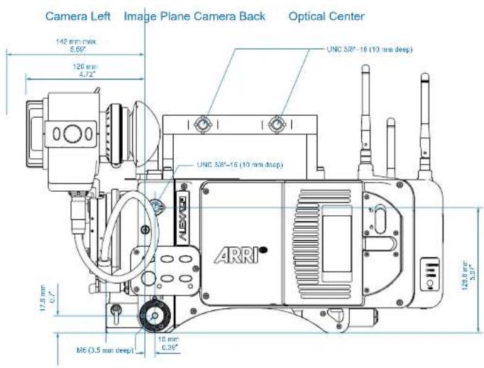
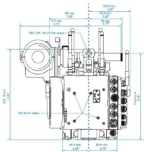
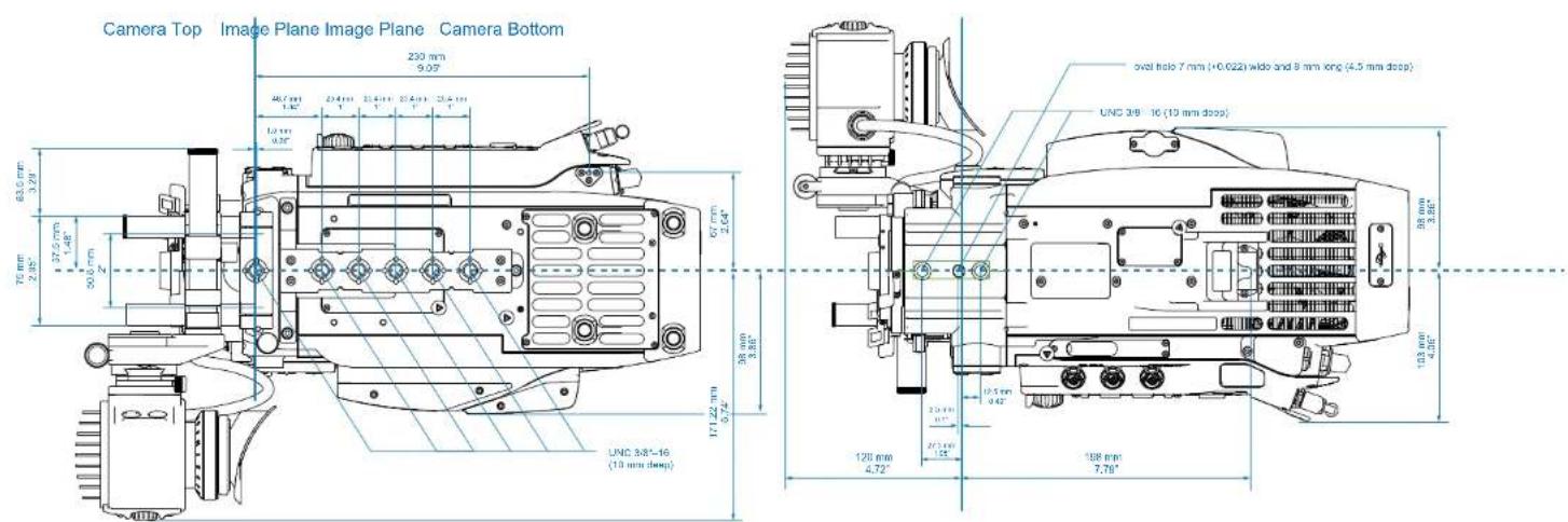
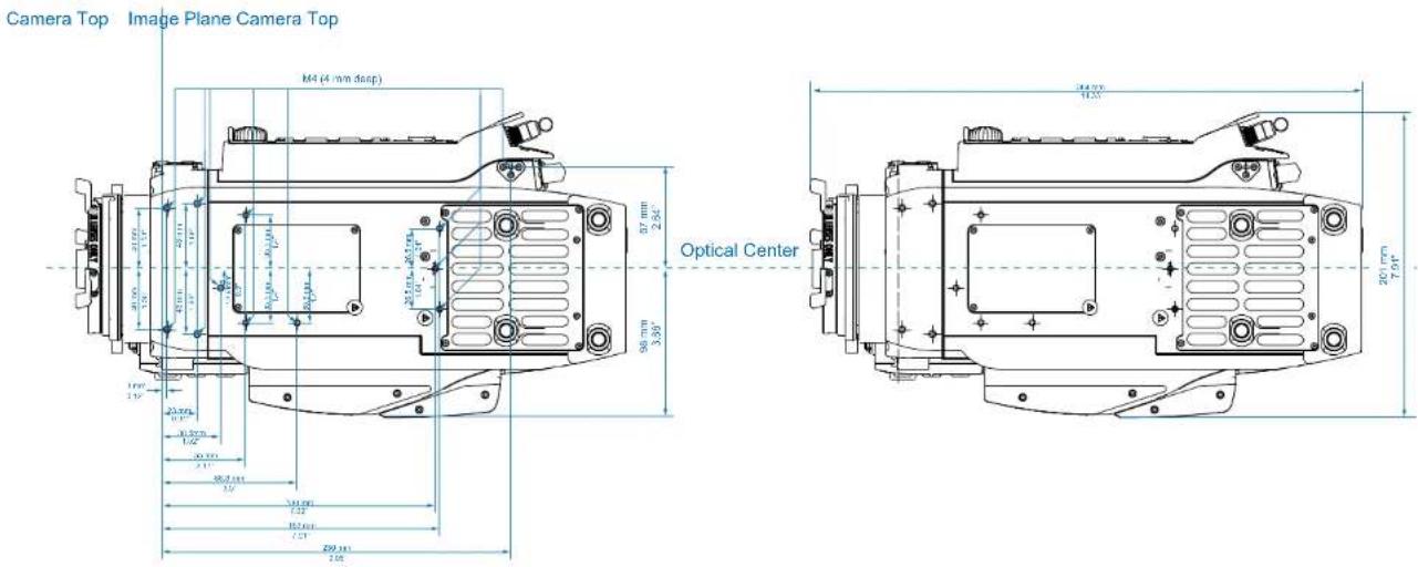


- Software Update Package 4.0
- Copyright
- Contents
- Connectors.... 30
- Recording Module.... 36
- Lens Mounting.... 40
- In-Camera Filter Module LF IFM.... 43
- Camera Controls....57
- Disclaimer
- About This Manual
- How to Use This Manual
- Scope
- Document revision history
- Version Release Date
- Introduction to the ALEXA LF
- Layout of the ALEXA
- Safety Guidelines
- Explanation of Warning Signs and Indications
- NOTICE
- General Safety Guidelines
- Specific Safety Instructions
- General Precautions
- Storage and Transport
- Condensation
- Sensor related image issues
- Single Frame Spots of Various Shape – also known as “Digital Dust” or “White Flecks”
- Flicker
- Rolling Shutter
- "Black Sun"
- Stuck Pixels at Long Exposure Times
- Stitching with ALEXA LF
- Power Supply
- Power Management
- BAT Connector
- Mains Unit NG 12/26 R
- To power the ALEXA using the Mains Unit NG 12/26 R:
- Cine-Style Block Batteries
- To connect the battery to the camera:
- Onboard Batteries
- V-Lock Batteries
- To attach a V-Lock battery:
- To release a V-Lock battery:
- Gold Mount Batteries
- To attach a Gold Mount battery:
- To release a Gold Mount battery:
- Power Outputs
- Camera Support
- Minimum Equipment Recommended For Operation
- Tripod and Remote Heads
- Electronic Viewfinder
- Viewfinder Cables
- Viewfinder Mounting Bracket
- Center Camera Handle CCH-1
- Bridge Plates BP-12/BP-13
- Bridge Plate adapter BPA-1
- Wedge Adapter WA-1 and Quick-Release Plate QR-HD-1
- Levelling Block LB-1
- Shoulder Pad SP-3
- Connectors
- Left column
- Right column
- BAT
- RET IN
- MON OUT 1/2/3
- EXT
- ETHERNET
- EVF
- AUDIO IN
- RS
- 12 V
- TC
- AUDIO OUT
- SD Card
- SD Card Requirements
- To format an SD card on the ALEXA:
- To create the required folder structure on the SD card in the ALEXA without formatting:
- LBUS Support
- LBUS Support
- CAUTION!
- Recording Module
- Inserting media:
- Removing media:
- Explanation of LED States
- Lens Mounting
- LPL mount
- To mount an LPL-mount lens:
- PL-to-LPL Adapter
- Lens Support
- In-Camera Filter Module LF IFM
- Benefits of in-camera filtration
- All benefits at a glance:
- Safety instructions for in-camera filtration
- Maximum lens mounting depth for PL lenses
- Basic precautions
- Required shimming and maximum lens mounting depth
- LF FSND Filter Set (Full)
- To insert or change a filter:
- Shimming the lens mount
- General shimming precautions:
- To compensate for the change in flange focal depth due to the shim:
- Tools needed:
- To shim the mount:
- Mounting in-camera filters
- To insert or change an in-camera filter:
- Filter cleaning
- To clean the filters:
- Camera Controls
- Main Controls
- Display
- To adjust the LCD brightness:
- Screen Buttons
- HOME screen
- Screen buttons
- COLOR Section
- Icons
- Lists and User Lists
- Adding a list value
- Deleting a list value
- DELETE SENSOR FPS
- FPS
- AUDIO
- SHUTTER
- EI
- COLOR
- MON OUT color spaces
- ARRI Look File 2 files
- To apply an ARRI Look File 2 file:
- To add an ARRI Look File 2 file to the camera:
- To delete an ARRI Look File 2 file from the camera:
- Playback and ARRI Look File 2 files
- WB
- Function Buttons
- TC
- SET TC
- TIMECODE
- OPTIONS
- TIMECODE OPTIONS
- INFO
- STATUS Info
- FPS Info
- USER
- PLAY
- CLIPLIST
- Wireless Remote System
- Radio System
- Setting the region of the wireless function
- Plus Camera Controls
- RADIO
- CAM LEVEL
- Level camera
- Reset motion sensor
- LENS DATA
- 85.0mm t 16.5
- LDA
- CLM screens
- Lens Motors
- Motor calibration
- Motor direction
- Motor torque
- 3D lens sync
- Lens Data Encoder LDE-1
- Hand Units
- Wireless Compact Unit WCU-4
- Single Axis Unit SXU-1
- Master Grips
- Operator Control Unit OCU-1
- emotion pan-bar and steady zoom
- Zoom Main Unit ZMU-3
- Wireless Zoom Extension WZE-3
- Hand Unit Priorization
- Menu
- Recording
- Apple ProRes™ codecs and resolutions
- ARRIRAW
- Monitoring
- MENU>MONITORING
- Electronic viewfinder >
- Sensor mode LF 16:9
- Sensor mode LF 2.39:1
- Sensor mode LF Open Gate
- Frame Lines Saved in Metadata
- Automated Dailies Creation
- Frame Lines in Post
- False Color Index
- Project
- Production Info
- System
- User Pixel Masking
- MENU>SYSTEM>IMAGING>UPM
- Install User Pixel Mask
- WiFi
- Devices supporting zeroconf
- Devices not supporting zeroconf
- MENU>SYSTEM>FIRMWARE
- Select update file
- Licensed Features
- Frame Grabs
- MENU>FRAME GRABS
- File format
- Jpeg
- Frame compare
- User Setups
- MENU>SETUPS
- Requirements:
- To save a user setup:
- To load a user setup:
- Operator controls
- EVF Controls
- Viewfinder EVF menu
- Viewfinder CAM menu
- Web Remote
- Connecting to the Camera
- Wireless Video
- Setting the region of the wireless video function
- Preparation
- Status LEDs
- Pairing camera and receivers
- Precondition:
- Pairing:
- Supported resolutions
- Sample setups
- Software update
- Operation of the Camera
- Internal recording
- Recording Module
- File System
- Internal Recording Formats
- ProRes
- ProRes RAID - Redundant Recording on SXR Capture Drives
- ProRes RAID for SXR Capture Drives
- Downloading ProRes RAID Data
- Choosing a Recording Format
- Media preparation
- File Structure for ProRes Recording
- File Structure for ARRIRAW Recording (Codex VFS)
- File naming scheme
- Examples
- Additional recommendations
- Metadata
- Monitoring
- Frame Lines
- Status Info Overlays
- Using Timecode
- External TC, Time of day
- Internal TC, Rec Run
- Syncing the Sensors of Two Cameras
- Synchronizing Image Output
- Syncing the Settings of Two Cameras
- Camera connection
- Camera setup
- Synced settings
- Remote Control Unit RCU-4
- Index
- 1
- A
- B
- C
- D
- E
- F
- G
- H
- L
- M
- N
- 0
- P
- R
- S
- T
- U
- V
- W
- Appendix
- Technical data
- Image Sensor
- Lens
- Image processing
- Viewfinder EVF-1
- Viewfinder EVF-2
- Power
- Recording
- Image Outputs
- Others
- HD video transmitter
- WiFi module
- Dimensions and weight
- Connector Pin Outs
- False Color Display
- Color Encoding
- Warning and Error Messages
- Special warnings and errors: Sensor temperature
- Status message
- Warning messages and meanings
- Dimensions and Weights
- Declarations of Conformity
- FCC Compliance Statement
- Industry Canada Compliance Statement
- China
- Taiwan
- 警語一
- 警語二
- 警語三
- Thailand
- United Arab Emirates
- ALEXA LF Length Width Height Weight
Brand : ARRI
Model : Alexa LF
Category : Camera