
ALEXA Mini - Camera ARRI - Free user manual and instructions
Find the device manual for free ALEXA Mini ARRI in PDF.


| Product Type | Digital Cinema Camera |
| Sensor | Super 35 CMOS, 3.4K (3392 x 2200) |
| Resolution | ARRIRAW up to 3.4K, ProRes up to 4K UHD |
| Frame Rates | Up to 200 fps (2K), 120 fps (3.4K) |
| Lens Mount | PL, interchangeable |
| ND Filters | Built-in motorized ND 0.6, 1.2, 1.8, 2.4 |
| Dimensions (L x W x H) | 200 mm x 200 mm x 167 mm |
| Weight (body only) | 2.3 kg (5.1 lbs) |
| Power Supply | 12-24 V DC, 80W typical consumption |
| Recording Media | SxS PRO+ / SxS-1, CFast 2.0 (via adapter) |
| Exposure Control | EI 160-3200, ARRI Log C |
| Monitor Output | SDI 12G/3G/HD, HDMI |
| Audio | 2-channel, 48 kHz, 24-bit |
| Operating Temperature | -20°C to +50°C (-4°F to +122°F) |
| Storage Temperature | -40°C to +60°C (-40°F to +140°F) |
| Maintenance | Clean sensor with approved kit; keep lens contacts clean; store in dry case |
| Safety | Use only ARRI-approved batteries and chargers; avoid exposing to rain or moisture |
| Spare Parts & Repairability | Authorized service centers; replaceable lens mount, fan, and sensor unit |
| Included Accessories | Body cap, Viewfinder bracket, 12-pin Fischer cable, power supply |
Frequently Asked Questions - ALEXA Mini ARRI
User questions about ALEXA Mini ARRI
0 question about this device. Answer the ones you know or ask your own.
Ask a new question about this device
Download the instructions for your Camera in PDF format for free! Find your manual ALEXA Mini - ARRI and take your electronic device back in hand. On this page are published all the documents necessary for the use of your device. ALEXA Mini by ARRI.
USER MANUAL ALEXA Mini ARRI
Software Update Packet 4.0
USER MANUAL
Date: 30th March 2016
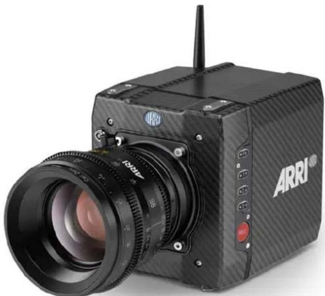
natural_image
Black ARRI ARRI camera with visible lens and control buttons (no text or symbols on body)Imprint
Copyright
© 2016 Arnold & Richter Cine Technik GmbH & Co. Betriebs KG. All rights reserved. No portions of this document may be reproduced without prior written consent of Arnold & Richter Cine Technik GmbH & Co. Betriebs KG. Specifications are subject to change without notice. Errors, omissions, and modifications excepted.
AMIRA, ALEXA, ALEXA XT, and ALEXA Mini are trademarks or registered trademarks of Arnold & Richter Cine Technik GmbH & Co. Betriebs KG. All other brands or products are trademarks or registered trademarks of their respective holders and should be treated as such.
Original version.
For further assistance
D-80799 Munich, Germany
E-mail: service@arri.com
www.arri.com/service
Document revision history
| Version | ID | Release | Date |
| 2.5 | 10001121 | K08771 | Preliminary version |
| 2.6 | 10001121 | K08878 | 14th July 2015 |
| 3.0 | 10001121 | K08941 | 02nd Nov 2015 |
| 4.0 | 10001121 | K09035 | 30th March 2016 |
Contents
1 For your safety / 为了您的安全.....7
1.1 Risk levels and alert symbols / 危险级别和警示标志.....7
2 Audience and intended use.... 11
3 Scope of delivery and warranty....12
4 Camera layout....13
4.1 Product identification.... 19
5 Power supply.... 20
6 Switching on/off....21
7 Connectors.... 23
7.1 Front connectors....23
7.2 I/O panel.... 24
7.3 Media panel.... 26
7.3.1 Preparing a USB memory stick....27
7.3.2 Changing a CFast 2.0 card....28
8 Lens mount/filters....30
8.1 ND filter module.... 30
8.2 Changing a lens.... 31
8.3 Lens control.... 32
8.3.1 Manual iris adjustment.... 32
8.3.2 Iris control via user button....33
8.3.3 Auto iris....34
9 Camera controls.... 35
9.1 Function button FN and camera buttons 1-3.... 35
9.2 Recording button.... 36
10 MVF-1 controls....39
10.1 EVF image/monitor.... 40
10.2 MVF-1 buttons.... 41
10.2.1 PK peaking button....41
10.2.2 EXP exposure tool button....42
10.2.3 VF1 & VF2 user buttons.... 43
10.2.4 PLAY button....43
10.2.4.1 Playback screen controls.... 44
10.3 Diopter adjustment.... 45
10.4 Adjusting the monitor....46
10.5 Changing the monitor mode....46
10.6 Live monitor.... 47
10.7 User monitor.... 48
10.8 Adjusting the monitor brightness....49
11 Overlay menu.... 50
12 Web remote....52
13 Home screen.... 55
13.1 Status section.... 57
13.2 ALERT messages....59
13.3 Info screens....60
13.4 FPS settings....65
13.4.1 Setting/adding an FPS value....65
13.4.2 Deleting an FPS value....67
13.5 TC settings....68
13.6 SHUTTER settings....71
13.6.1 Selecting a SHUTTER unit....71
13.6.2 Setting/adding a SHUTTER value....73
13.6.3 Deleting a SHUTTER value....74
13.7 WB settings.... 76
13.7.1 Setting/adding a WB value....76
13.7.2 Renaming a WB value....77
13.7.3 Deleting a WB value.... 78
13.7.4 WB Options....80
13.8 LOOK and gamma settings....80
13.8.1 Setting the LOOK file....80
13.8.2 Setting Gamma....82
13.8.3 Adding a LOOK file.... 83
13.8.4 Deleting a LOOK file.... 85
13.8.5 Exporting a LOOK file....87
13.8.6 Duplicating/renaming a LOOK file....89
13.8.7 LOOK parameters....90
13.8.7.1 ASC CDL Transforms....90
13.8.7.2 3D LUT and video look parameters....91
13.8.8 LOOK editing....91
13.9 EI settings....94
13.9.1 EI technical details.... 96
14 Camera menu....97
15 MENU > Recording....98
15.1 Recording Codec....98
15.1.1 ARRIRAW....98
15.2 Resolution....99
15.2.1 4:3 Recording....99
15.3 Project settings.... 100
15.3.1 Project rate.... 100
15.3.2 Next reel count.... 101
15.3.3 Camera Index....101
15.3.4 Camera ID prefix....101
15.3.5 Lens squeeze factor....101
15.4 Record mode.... 102
15.5 Rec beeper / tally.... 103
15.6 Pre-recording.... 103
15.6.1 How to activate pre-recording.... 104
15.6.2 Pre-recording maximum duration.... 104
15.7 Audio recording.... 105
16 MENU > Media.... 106
16.1 Erase CARD....106
16.2 Delete last clip....108
16.3 Prepare USB medium.... 109
17 MENU > Monitoring.... 112
17.1 EVF/Monitor.... 112
17.1.1 Surround view....112
17.1.2 Zoom position.... 113
17.1.3 Exposure tool....113
17.1.4 Peaking....114
17.1.5 Settings.... 115
17.1.6 EVF overlays / Monitor overlays / SDI overlays.... 115
17.2 SDI....117
17.3 Frame lines....120
17.3.1 Setting/adding a frame line.... 122
17.3.2 Deleting a frame line.... 125
17.3.3 User rectangle 1 & 2.... 126
17.4 Color bars.... 126
18 MENU > System....127
18.1 Sensor....127
18.2 Fan mode.... 128
18.3 Power....129
18.4 System time + date.... 129
18.5 Buttons + display....130
18.6 Network / WiFi.... 131
18.7 Camera update....131
19 MENU > Setup....133
20 MENU > User buttons.... 135
21 MENU > Metadata.... 139
22 MENU > Electronic Control System (ECS)....140
22.1 Radio....140
22.2 Lens data....141
22.3 Calibrate all motors.... 145
22.4 Lens motor focus....146
23 Camera preparation....147
23.1 Adjusting the MVF-1....147
23.2 Mounting to a bridge plate.... 148
24 Assembly and retrofits.... 151
24.1 MVF-1 and EVF cable....151
24.2 Camera handle.... 153
24.3 Antenna....154
24.4 Changing a lens mount.... 155
24.5 CCP-1.... 157
24.6 Transvideo StarliteHD5-ARRI Monitor....159
25 Licensing and updating.... 162
25.1 Camera update....162
25.2 Licensing....164
25.2.1 Extracting HW INFO from the camera.... 165
25.2.2 Installing a license file.... 165
25.2.3 Deleting a license....166
26 Appendix....168
26.1 Technical data....168
26.2 Dimensional drawings.... 173
26.3 Pin-outs....173
26.4 Declarations of conformity....176
Safety warnings, safety alert symbols, and signal words in these instructions indicate different risk levels:
DANGER!
DANGER indicates an imminent hazardous situation which, if not avoided, will result in death or serious injury.
WARNING!
WARNING indicates a potentially hazardous situation which, if not avoided, may result in death or serious injury.
CAUTION!
CAUTION indicates a potentially hazardous situation which, if not avoided, may result in minor or moderate injury.
NOTICE
NOTICE explains practices not related to physical injury. No safety alert symbol appears with this signal word.
Note: Provides additional information to clarify or simplify a procedure.
High voltage! Risk of electric shock and fire!
Short-circuits may entail lethal damage!
Before use, read and follow all valid instructions.
Use solely and exclusively as described in the instructions.
Never open. Never insert objects.
For operation, always use a power source as indicated in the instructions.
Always unplug the power cable by gripping the power plug, not the cable.
Never try to repair. All repair work should be done by a qualified ARRI Service Center.
Never remove or deactivate any safety equipment (incl. warning stickers or paint-marked screws).
Always protect from moisture, cold, heat, dirt, vibration, shock, or aggressive substances.
Never cover any fan openings.
危险
高电压!有触电或起火风险!
短路将引起致命危险。
Condensation! Risk of electric shock and fire!
Condensation may form on the sensor and electrical connections when exposing the camera to sudden changes of temperature or humidity!
To avoid injury and damage, never operate the camera when condensation occurs.
小心
冷凝!有触电或火灾风险!
Heavy weight! Risk of injury and damage!
If placed on an unstable surface, the camera can fall and cause serious harm!
Always place the camera on proper support devices. Safely attach it as described in the instructions.
⚠ 小心
设备重量较大!有受伤或设备损坏风险!
Hot surfaces! Risk of injury and damage!
During extended operation or operation in high ambient temperatures, the fan outlet at the camera rear, the CFast drive and the CFast card can get hot.
Never cover, obstruct or block the fan in- or outlets while the camera is powered.
1.3 General precautions / 般安全措施
NOTICE
Even rugged cameras use components sensitive to improper use.
Always unplug the camera from power sources before making changes to the setup or system (in particular: changing cables).
Direct sunlight can result in camera housing temperatures above 60 °C (140 °F). At ambient temperatures above 25 °C (77 °F), protect the camera from direct sunlight.
Protect the optical system and sensor: Never point the camera or viewfinder into direct sunlight.
Avoid permanent sensor damage: Never let any direct light or reflections from high-energy light sources (e.g. laser beams) enter the camera's optical path.
Protect the sensor: Always keep a lens or protective cap on the empty lens mount. Change lenses in dry, dust-free environments only.
Always clean the sensor cover glass according to ARRI instructions.
Only use the tools, materials and procedures recommended in this document. For the correct use of other equipment, see the manufacturer's instructions.
提示
2 Audience and intended use
NOTICE
The product is solely and exclusively available for commercial costumers and shall be used by skilled personnel only. Every user should be trained according to ARRI guidelines.
Use the product only for the purpose described in this document. Always follow the valid instructions and system requirements for all equipment involved.
The ALEXA Mini is a 35 mm digital camera solely and exclusively for recording images at various resolutions suitable for a variety of distribution formats:
- ProRes 422, ProRes 422 HQ, ProRes 4444, ProRes 4444 XQ, and ARRIRAW* codec
- REC 709 encoding (through use of look files), Log C or ARRIRAW* encoding
- CFast 2.0 card recording
- Up to 200 fps with full image quality
- 35 mm CMOS sensor in 16:9 or 4:3* modes
• EVF with OLED eyepiece - Fold-away monitor for both live view and user interface access
- Small and lightweight built for high mobility and special applications
* Feature requires licensing.
3 Scope of delivery and warranty
NOTICE
Product and packaging contain recyclable materials. Always store, ship, and dispose of according to local regulations.
ARRI is not liable for consequences from inadequate storage, shipment or disposal.
Delivery
On delivery, please check if package and content are intact. Never accept a damaged/incomplete delivery. A complete delivery includes:
- ALEXA Mini camera with lens mount according to order: titanium PL, AMIRA PL, EF
- Antenna
- USB memory stick
• 3 mm Allen key - Quick Guide
• Original packaging incl. drying agent
NOTICE
ARRI offers an increasing variety of product bundles and additional accessories.
For details, please consult our website or your local ARRI Service Partner.
Warranty
For scope of warranty, please ask your local ARRI Service Partner. ARRI is not liable for consequences from inadequate shipment, improper use, or third-party products.
4 Camera layout
Right
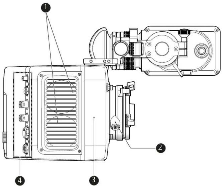
1 Fan intake
2 LBUS connector
3 integrated WiFi antenna
4 I/O panel
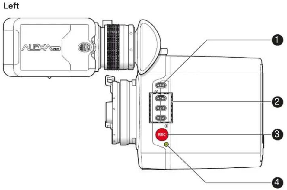
1 Function button
2 Camera buttons 1-3
3 Recording button
4 Status LED
Top
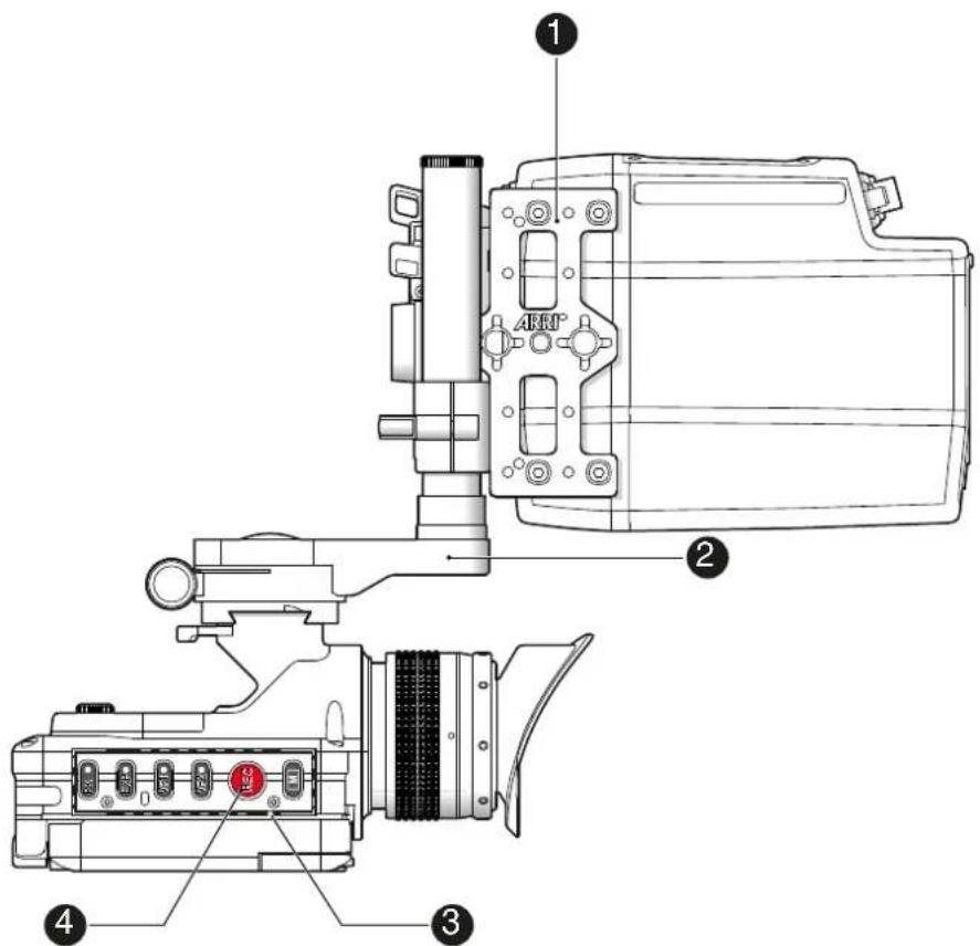
1 MAP-1
2 MVB-1
3 MVF-1 buttons
4 Record button
Bottom
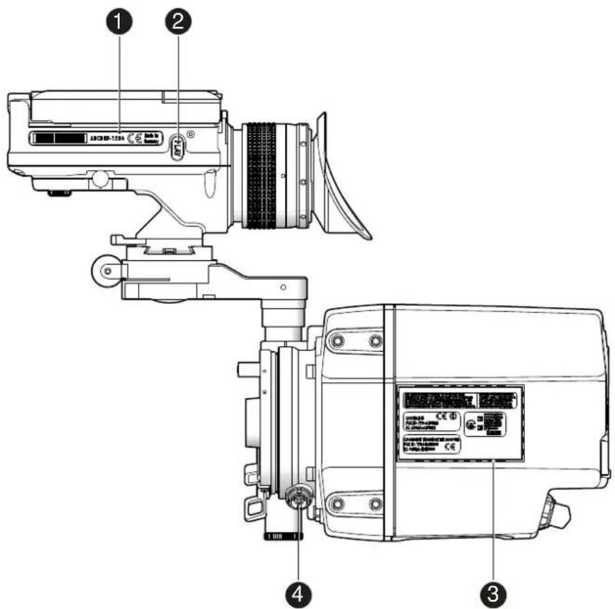
1 MVF-1 type label
2 PLAY button
3 Camera type labels
4 LBUS connector
Front
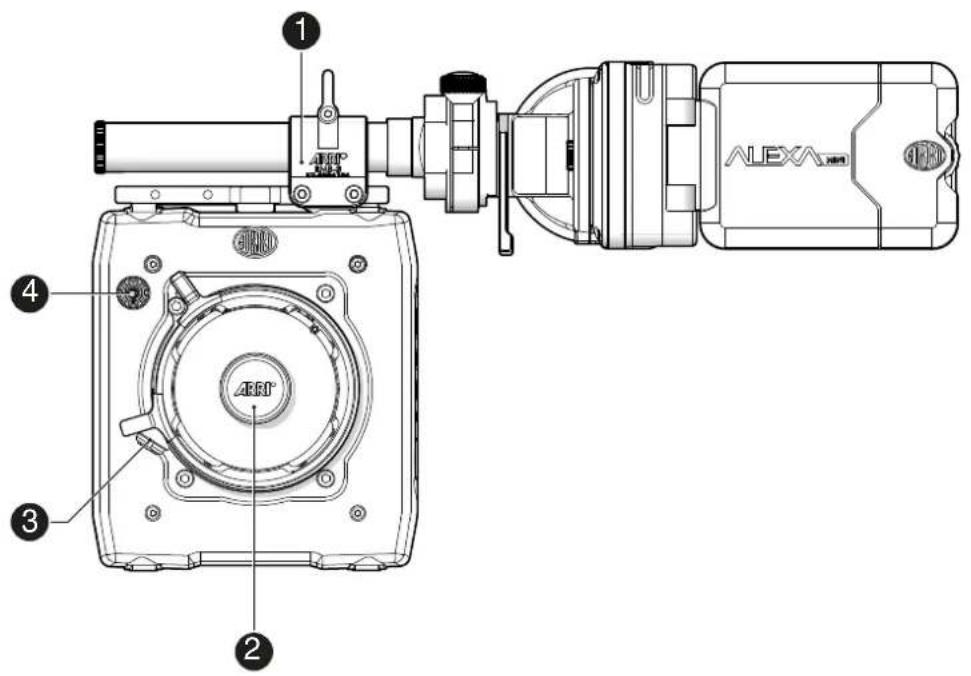
1 RMB-3
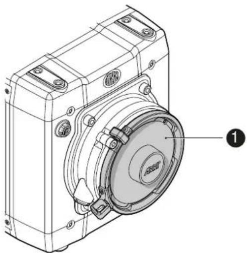
2 Lens mount (here: titanium PL)
3 LBUS connector
4 Audio connector
Back
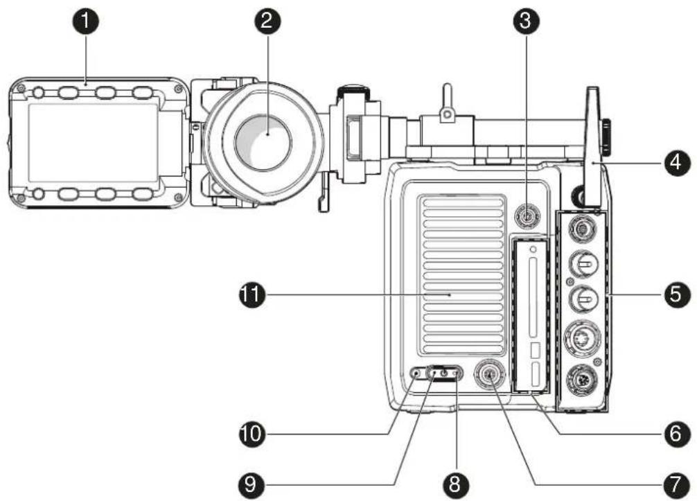
1 Fold-away monitor (MVF-1)
2 OLED eyepiece
3 Timecode connector
4 White radio antenna
5 I/O panel
6 Media panel (CFast 2.0 card slot, USB)
7 Ethernet connector
8 Boot status LED
9 Power button
10 Recording status LED
11 Fan outlet
CAUTION!
Hot surfaces! Risk of injury and damage!
During extended operation or operation in high ambient temperatures, the fan outlet at the camera rear, the CFast drive and the CFast card can get hot.
Never cover, obstruct or block the fan in- or outlets while the camera is powered.
4.1 Product identification
natural_image
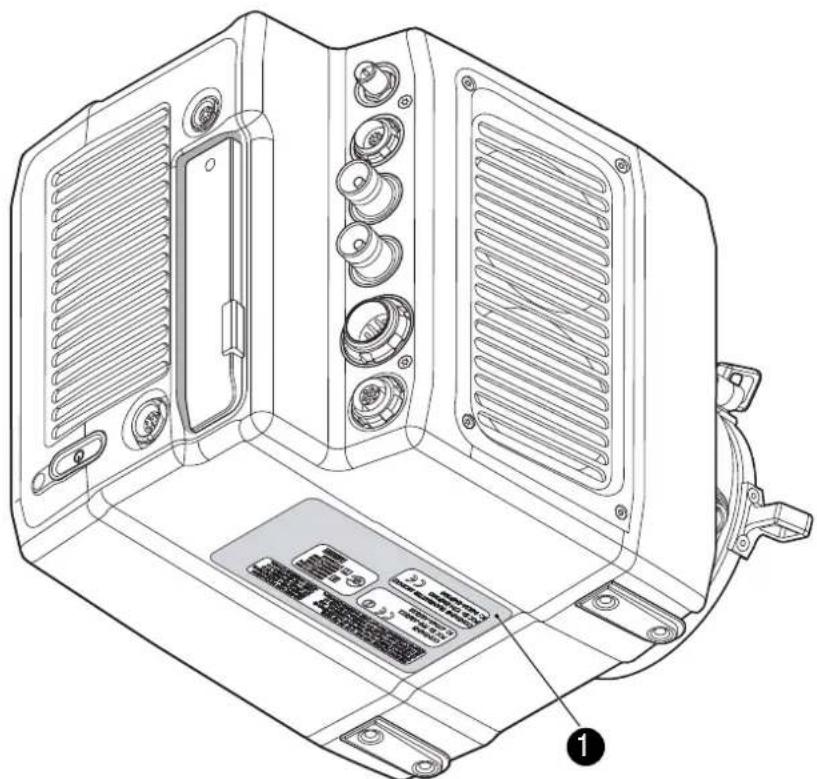
Technical line drawing of a computer case with ventilation grilles and labeled components (no text or symbols beyond basic diagram)The FCC conformity label and the CE type label with serial number (1) are on the camera bottom. The serial number consists of the last 5 digits of the equipment number K1.0003873-XXXXX.
5 Power supply
The camera power is supplied by external power sources only.
NOTICE
If the power supply is interrupted with the camera switched on, the camera will automatically repower and boot-up on reconnection.
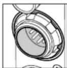
Use the 8-pin LEMO connector and a KC50-S or KC50-SP-S cable to supply the camera with 10.5 to 34 V DC.
6 Switching on/off
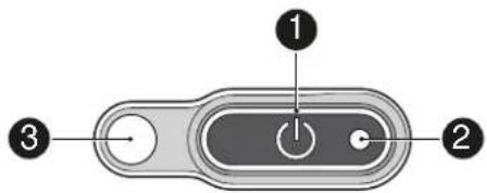
NOTICE
Before switching on, ensure that the camera is connected to an external power source.
The power button background illumination is on when the power is in the valid range.
To switch on the camera:
▶ Press the power button (1).
The camera starts booting. The boot status is indicated as follows:
| Boot status LED (2) is... Camera | |
| flashing blue is booting | |
| solid blue has finished the boot process |
For mounted MVF-1 only: During the boot process, the ARRI logo appears in the monitor of the MVF-1 (4).
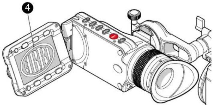
To switch off the camera:
▶ Press and hold the power button (1) until the camera has switched off and the boot status LED (2) turns off.
For mounted MVF-1 only: On the monitor of the MVF-1, a countdown appears. On reaching zero, the camera switches off.
To check the recording status
The recording status is indicated as follows:
| Record status LED (3) is... Camera is... | |
| solid green ready for recording | |
| solid red recording | |
| off not ready for recording. Check, if | the CFast 2.0 card is valid. If not:Insert a valid CFast 2.0 card. See page 147. |
| flashing green/red alternately not ready for recording due to an error.Check alert screen on MVF-1 for reasons.Reboot camera. | |
NOTICE
The recording status is also visible in the home screen, the live screen, the EVF image, and the SDI image.
7 Connectors
NOTICE
Connecting or disconnecting devices or cables while recording can disturb the audio/image signal due to static electricity.
7.1 Front connectors
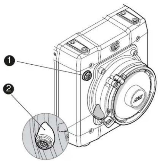
1 Audio in
2 L-Bus
Audio in (5-pin LEMO)
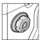
2-channel line level audio input.
LBUS (4-pin LEMO)
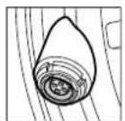
LBUS output for daisy-chainable active lens motors.
Supports CMotion cforce motor and ARRI cforce mini motor.
7.2 I/O panel
NOTICE
If the power supply is interrupted with the camera switched on, the camera will automatically repower and boot-up on reconnection.
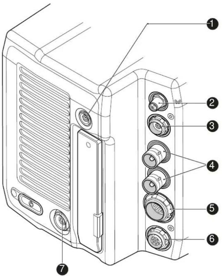
1 Timecode connector 5 BAT main power in
2 White radio antenna 6 EXT connector
3 MVF-1 or CCP-1 7 Ethernet connector
4 HD-SDI image out 1 & 2
TC (5-pin LEMO)
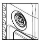
The TC connector is a 5-pin LEMO socket. It accepts and distributes LTC (Longitudinal Time Code) signals.
Note: The camera has a TC buffer to keep a synced external TC for up to three minutes while camera power is disconnected.
White radio antenna
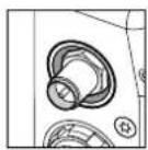
Mounting point for white radio antenna for lens control.
NOTICE
Do not leave the antenna connector open during operation or transport. The radio module inside could be damaged by electrostatic discharge on the open connector. ARRI recommends using the originally supplied antenna only (order number: K2.0001996).
EVF (16-Pin ODU)
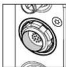
Hot swappable interface for MVF-1 or CCP-1.
SDI OUT 1 & 2 (BNC)
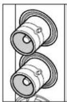
Both BNC outputs deliver image outputs in 1920 x 1080 422 1.5G, 422 3G, 444 3G and 422 6G* single link formats. Through a hardware modification, SDI 2 can be reconfigured into a SYNC connector for analog genlock signals (Black burst, Tri-level sync). Please contact an ARRI camera service center for more information.
*Only on SDI 2 in UHD recording format
BAT (8-pin LEMO)
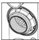
Via cables KC50-S (2 m, straight) and KC50-SP-S (coiled), this main power supply input accepts 10.5 to 34 V DC.
EXT (7-pin LEMO)
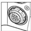
A connector for external accessories, carrying two CAN buses and accessory power output at camera voltage level (1.0 A max.). With an external adapter, R/S functionality is supported.
ETH (10-pin LEMO)
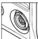
Standard Ethernet connectors don't deliver the durability and reliability required by ARRI, so ALEXA Mini uses a 10-pin LEMO connector. A special cable, available from ARRI (model KC-153-S), is required to connect the Ethernet connector to a standard RJ-45 Ethernet connector.
Note: The RCU-4 cannot be used with an ALEXA Mini.
7.3 Media panel
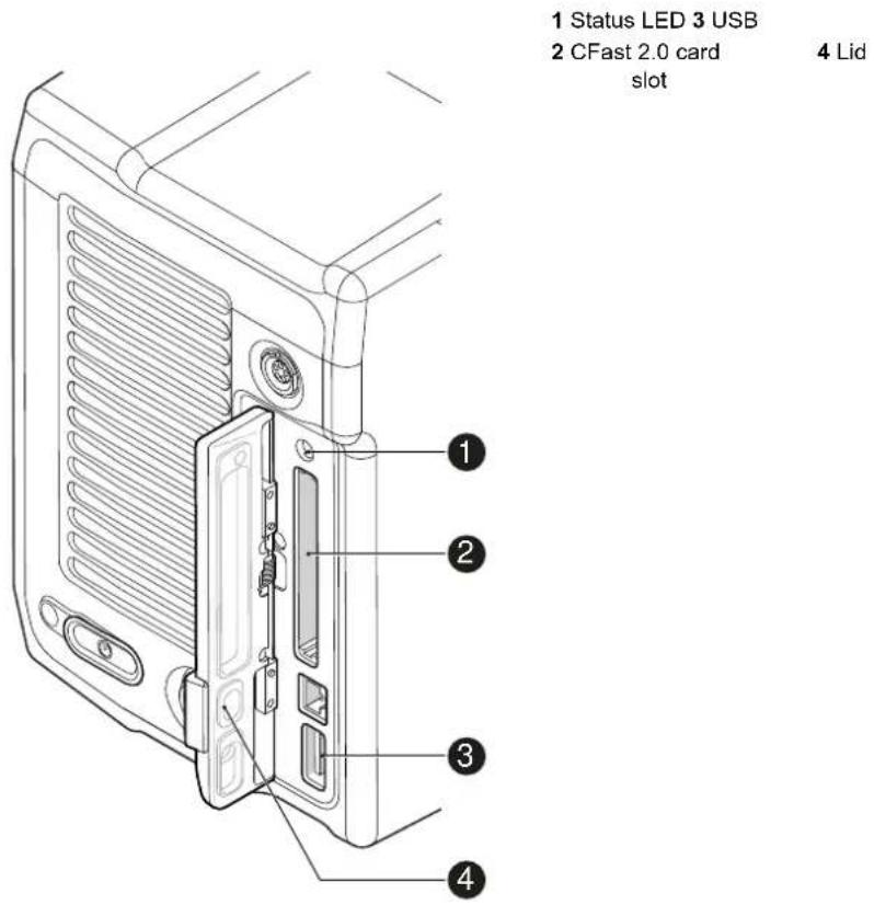
Card (CFast 2.0)
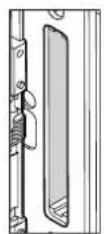
Storage media slot for CFast 2.0 recording cards.
USB
Interface for USB memory sticks with FAT file system. Can also be used to charge USB devices. Supplies 5V with a maximum current of 500mA.
7.3.1 Preparing a USB memory stick
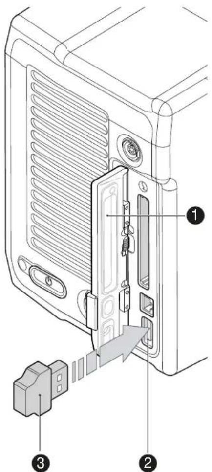
USB memory sticks for the ALEXA Mini must have a specific folder structure which can be created with the camera.
- To prepare a USB memory stick: Open the media lid (1).
- Connect a FAT-formatted USB stick (3) to the camera (2).
- Note: To avoid file corruption, never remove the USB stick during write access.
- Via jogwheel, open MENU > Media > Prepare USB medium.
7.3.2 Changing a CFast 2.0 card
NOTICE
ALEXA Mini does not accept ALEXA-formatted CFAST 2.0 cards, and vice versa.
Before using a CFAST 2.0 card with ALEXA Mini, you must erase it in-camera to create the required file system.
Avoid damage to the contacts of both camera and card. Always insert cards as described in this document.
Never change memory cards when recording - this may damage the recorded clip.
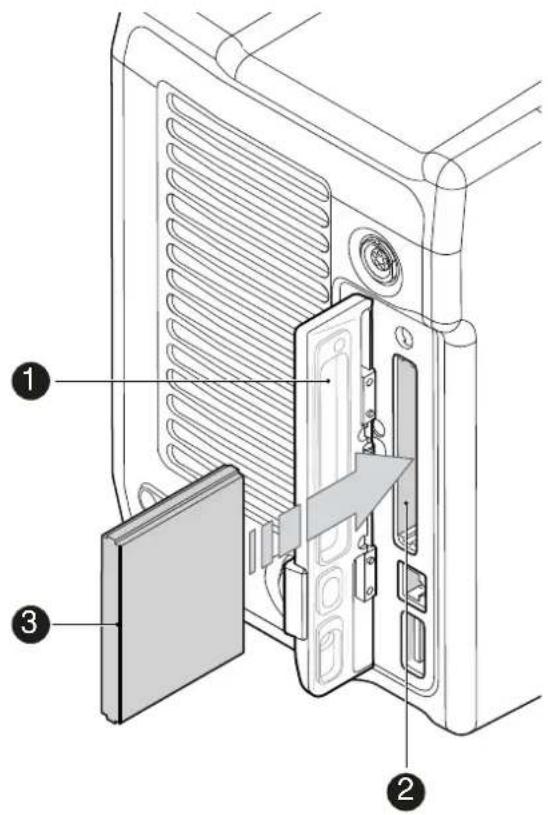
- Open the lid (1).
- Align the card's positive edge (3) facing the camera rear.
- With the contact pins first, gently insert the card, until it audibly locks (2).
- Gently close the lid (1). Never force it closed on an unlocked card.
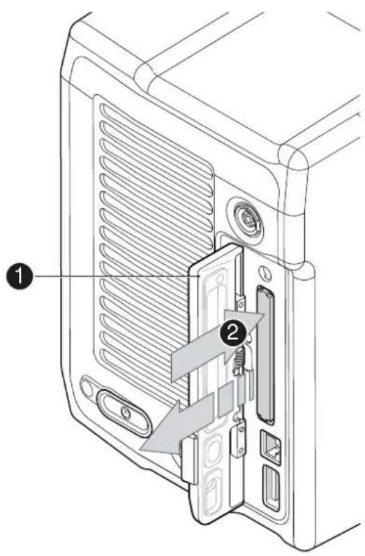
- For card removal: Open the lid (1).
- Push the card in until it audibly unlocks (2).
- Remove the card.
8 Lens mount/filters
natural_image
Technical line drawing of a mechanical device with mounting holes and a central circular component (no text or symbols)1 Lens mount (here: titanium PL)
Cooke /i support
The camera supports the Cooke /i protocol for lenses running FW versions according to the following table.
| Lens type FW version | |
| S4 /i Prime lens (10-bit) 0.29 or higher | |
| S4 /i Prime lens (12 bit) 0.39 or higher | |
| S4 /i Zoom lens (10 bit) 1.29 or higher | |
| S4 /i Zoom lens (12 bit) 1.39 or higher |
The FW version can be retrieved from the lens with the Cooke Viewer Lens Display program. For detailed info, please contact Cooke Optics directly.
8.1 ND filter module
NOTICE
ALEXA Mini uses FSND (Full Spectrum Neutral Density) filters, which are linear across the full spectrum of the camera sensor. This prevents artifacts from infrared wavelengths and the need for additional IR filters.
The camera contains an internal ND filter module, consisting of ND 0 (Clear), 0.6, 1.2 and 2.1 filters. The filters can be operated via user buttons, MVF-1, web remote, or WCU-4.
8.2 Changing a lens
NOTICE
Protect the sensor: Always keep a lens or protective cap on the empty lens mount.
Change lenses in dry, dust-free environments only.
Never exceed the maximum lens dimensions.
Have every lens properly shimmed as prescribed by the manufacturer.
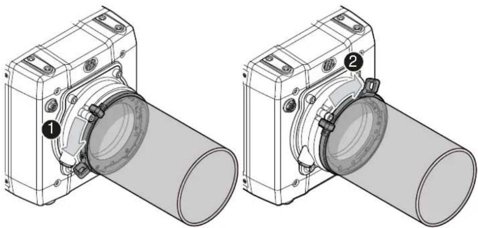
PL mount
natural_image
Technical line drawing of two mechanical components with numbered callouts (1 and 2), no text or symbols present.Note: Please use a lens support system for PL lenses above 3 kg/6.6 lbs.
- Observe maximum lens dimensions.
- Unlock the lens mount counter-clockwise (1) and remove the lens or cap.
- Never touch the sensor.
- Either: Mount the next lens and lock (2) the lens mount clockwise.
- Or: Always cap and lock (2) an empty lens mount clockwise.
EF mount
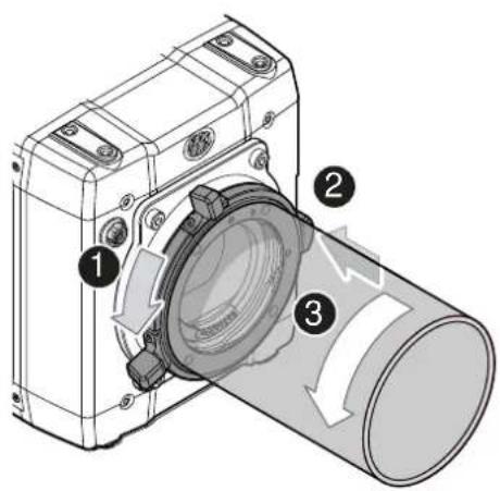
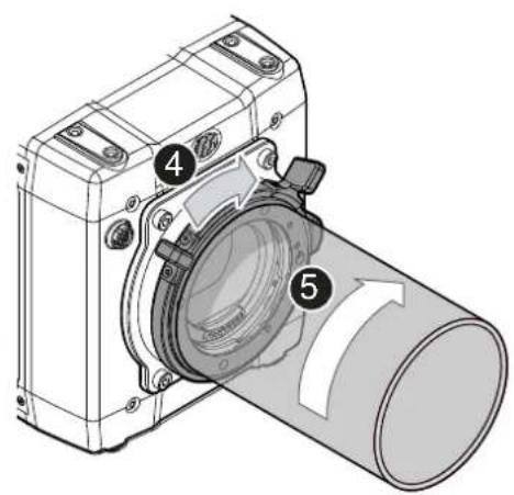
Note: Please use a lens support system for EF lenses above 3 kg/6.6 lbs.
- Observe maximum lens dimensions.
- Turn the lever counter-clockwise (1) to unlock the mount.
- Either: Remove the cap.
- Or: Press and hold the button (2) to unlock the lens.
- Turn the lens (3) counter-clockwise, then remove it.
-
Never touch the sensor.
-
Either: Mount the next lens:
o Align the dots of both lens and lens mount.
o Push the lens into the mount.
o Turn the lens clockwise (5) until the bayonet locks.
o Turn the lever clockwise (4) to tighten the lens to the lens mount.
- Or: Always cap the empty lens mount.
8.3 Lens control
Control of lens iris is possible with ENG PL mount and EF lenses. You can control the iris manually, via user button, or via auto iris.
8.3.1 Manual iris adjustment
HOME > EI > IRIS
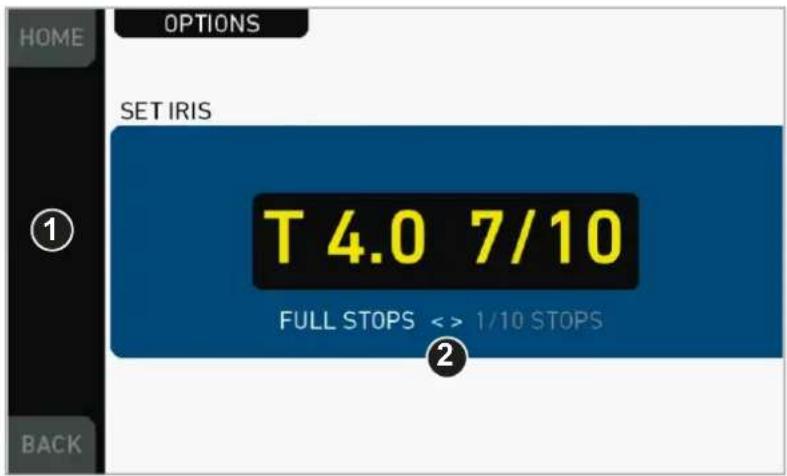
Pressing the wheel (1) changes the step size between full and sub-stops (2). Note: Sub-stop precision depends on the lens type and is automatically set by the camera.
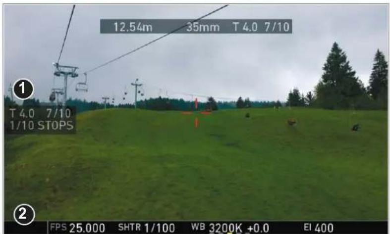
On the live screen, you can activate and deactivate iris adjustment (1) by short-pressing the lower round (not oval!) button (2). Keeping the button pressed (2) activates iris adjustment until it is released. (2). Note: Depending on the image flip, the round buttons may appear on the right.
8.3.2 Iris control via user button
MENU > User button > Button X
For iris control, assign one user button each with Open Iris and Close Iris. See page 135.
8.3.3 Auto iris
HOME > EI > IRIS > OPTIONS
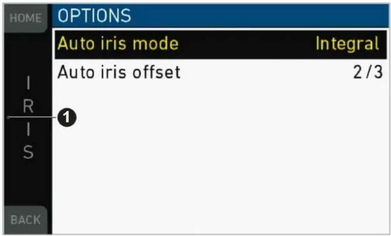
Via jogwheel (1), you can define the auto iris behavior.
Auto iris mode: Defines the iris calculation:
- Integral: Iris is calculated based on full image content.
- Center: Iris is calculated with higher priority on image center.
Auto iris offset: Corrects the auto iris calculation result by up to +/- 3 stops in 1/3 stop step sizes. Activate via user button.
9 Camera controls
In this chapter the camera controls of the Alexa Mini are shown.
9.1 Function button FN and camera buttons 1-3
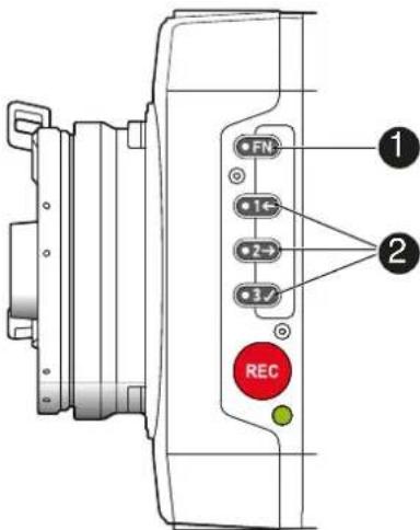
Camera buttons as user buttons:
By default, the camera buttons 1 to 3 function as user buttons.
- In the camera menu (MENU > User buttons > Camera user buttons), set the desired functions to the user buttons.
The functions are assigned to the user buttons.
- Press a user button (2) to trigger its function.
Depending on the assigned user button function, the LED reflects the function state.
Camera buttons to control standard camera functions:
▶ Press and hold the function button (1); then press a camera button (2). If a simultaneous press cannot be performed, the FN button can be pressed twice within 0.5 seconds to bring the camera buttons into function selection mode for 2 seconds. During these two seconds, pressing a camera button will de-/activate its assigned function.
The LED of the FN button reflects that a standard function is active. An LED on each button reflects the functional status.
The following standard functions can be triggered:
| Function button & camera button | Function |
| 1 Toggles the overlay menu of the Live view. In the overlay menu, the camera buttons control the following functions: | |
| Function button & camera button | Function | |
| User button Function | ||
| 1 Select Backward | ||
| 2 Select Forward | ||
| 3 Confirm | ||
| 2 Arms the card erase. | To trigger the card erase, press user button 3 twice.Any other button can be pressed to cancel the action.After the erase, the overlay can be reset by pressing any button. | |
| 3 Starts/stops the playback. | During playback, the cam-era buttons control the following functions: | |
| User button Function | ||
| 1 Skip Backward | ||
| 2 Skip Forward | ||
| 3 Play/Pause | ||
Overlay menu
The overlay menu allows the user to control the basic camera parameters FPS, Shutter, Exposure Index, ND filter and WB.
It can be activated and deactivated by pressing the buttons FN+1.
The overlay menu is active on the EVF and monitor images of the MVF-1, as well on the SDI out (if SDI processing is activated).
See chapter "Overlay menu" for detailed info.
9.2 Recording button
| NOTICE |
| Pressing a recording button returns the MVF-1 user interface to the home screen and disables the menu access. |
| Recording also disables the home screen buttons for FPS, TC, Shutter, and Look settings. |
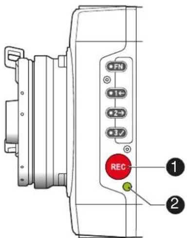
To start recording:
Prerequisite: The camera is prepared.
-
Preset all buttons.
-
Press REC (1) on the left camera side.
The camera starts recording. The recording status LED (2) reflects the recording status:
| Recording statusLED (2) is... | Camera is... |
| solid green ready for recording | |
| solid red recording | |
| flashing red Recording starts/stops | |
| off not ready for recording. Check if the CFast 2.0 cardis valid. If not: Insert a valid CFast 2.0 card. Seepage 147. | |
| flashing green/redalternaterly | not ready for recording due to an error. |
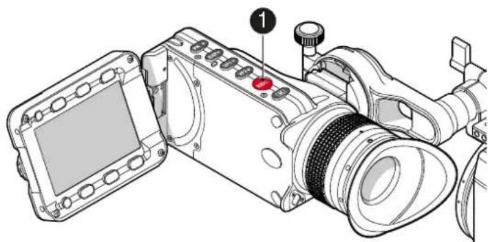
- For mounted MVF-1 only: Press REC (1) on the MVF-1:
natural_image
Technical line drawing of a digital camera with labeled component (no text or symbols present)NOTICE
Never change memory cards when recording - this may damage the recorded clip.
NOTICE
Connecting or disconnecting devices or cables while recording can disturb the audio/image signal due to static electricity.
10 MVF-1 controls
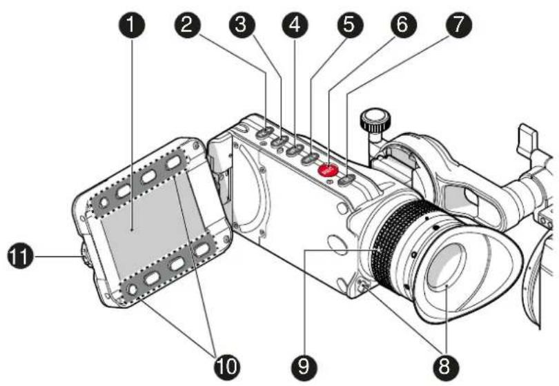
1 Monitor (Live & GUI) 7 Monitor button
2 Peaking button 8 Proximity sensor
3 Exposure tool button 9 Diopter control
4 VF-1 user button 10 Screen buttons
5 VF-2 user button 11 Jogwheel
6 Recording button
Proximity sensor
This infrared sensor automatically deactivates the MVF-1's internal OLED panel when you withdraw your eye. The sensor is placed either on the bottom left-hand side of the viewfinder (Generation 1), or it is integrated in the eye cup (Generation 2).
The Alexa Mini MVF-1 contains the generation 2 proximity sensor.
NOTICE
To avoid hardware damage, always keep the sensor unobstructed.
10.1 EVF image/monitor
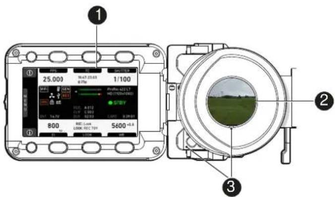
When you look through the eyepiece, the proximity sensor (3) activates the EVF display (2).
You can add status data from the home screen (1) to the MVF-1 image (2).
If activated, overlays around the EVF image show essential camera, audio, and recording statuses.
You can modify/deactivate these status bars via the EVF overlays and EVF status components menu. For more details, see the User manual.
Note: In Overlay mode (see below), all status bars appear on the active MVF-1 image.
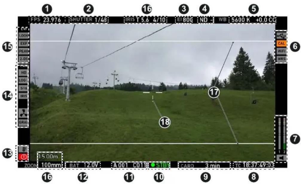
1 Sensor FPS 10 Camera status
2 SHUTTER value 11 Reel and clip info
3 El Exposure index
4 Internal ND filter
5 WB White balance
6 Icons for USB status, lens motor calibration request, WiFi status
7 Audio status 16 LDS info
8 TC Timecode (if enabled) 17 Framelines
9 CARD capacity/status
12 BAT level/status
13 Alert and temperature status
14 Camera settings icon (Recording resolution, Rec gamma, S16 (if S16 mode is active), Iris, Fan status, Framegrab, Camera lock)
1 Safe mode
In Safe mode, all status bars appear in a black frame (1) outside the active MVF-1 image.
Note: If surround view is active, the area is marked by a surround mask.
10.2 MVF-1 buttons
10.2.1 PK peaking button
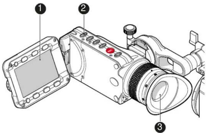
- To activate peaking on monitor (1) and MVF-1 (3): Press PK (2).
- Peaking highlights the image parts that are in focus for better focus judgement.
- For PK settings: Go to MENU > Monitoring > EVF/Monitor > Peaking.
10.2.2 EXP exposure tool button
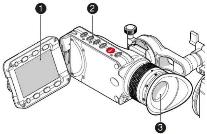
The EXP button (2) activates the set exposure tool on the monitor (1) and EVF image (3). Use the tool for evaluation of the image exposure levels. An activated tool lights up the button (2).
For EXP setting: Go to MENU > Monitoring > Exposure tools.
In Zebra mode, the tool overlays up to two luminance ranges with diagonal stripes. High zebra ranges above, Mid zebra around the user-defined luminance value.
False color mode overlays predefined luminance ranges as follows:
| Luminance range | Signal level | Color |
| White clipping | 100 to 99 % | Red |
| Just below white clipping | 99 to 97 % | Yellow |
| One stop over medium gray (Caucasian skin) | 56 to 52 % | Pink |
| 18 % medium gray | 42 to 38 % | Green |
| Just above black clipping | 4.0 to 2.5 % | Blue |
| Black clipping | 2.5 to 0.0 % | Purple |
10.2.3 VF1 & VF2 user buttons
natural_image
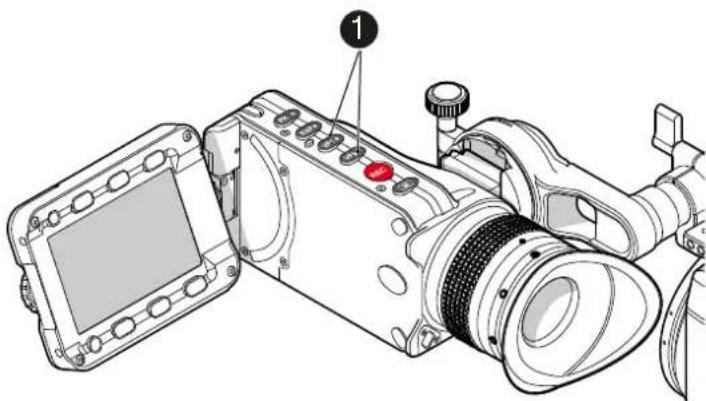
Technical line drawing of a digital camera module with labeled component (1), no readable text or symbols beyond the label- Via the user button menu (see "Presetting user (and VF) buttons"), you can assign a function to both VF1 and VF2 buttons (1).
10.2.4 PLAY button
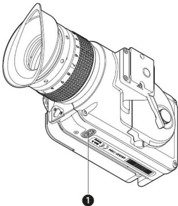
- Press PLAY (1) for one second to see the last clip of the active CFast 2.0 card. o Playback is active on monitor, on EVF and on SDI out.
- You may toggle between play and pause by briefly pressing PLAY (1) again.
- To exit playback: Press PLAY (1) for one second.
- Extended playback control is available via the on-screen navigation (see below).
10.2.4.1 Playback screen controls
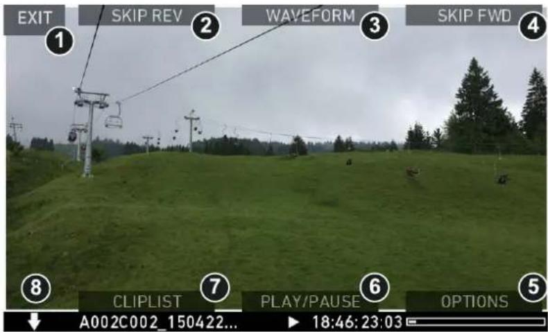
- Playback loads the last active clip (paused on the first frame).
- Press ARROW (8) to hide/show button info overlays
- To toggle between PLAY/PAUSE: Press the lower mid screen button (6) or the jogwheel.
- While paused: Scroll up/down via the jogwheel to load the next/previous frame.
- While playing: Scroll up/down via the jogwheel to increase or decrease the playback speed up to 16x both forward and backwards.
- Press SKIP FWD (4) to load the next available clip.
- Press SKIP REV (2) to load the previous available clip.
- Press WAVEFORM (3) to set waveform overlay on monitor.
- Press CLIPLIST (7) to select another clip for playback from a list of all clips on the inserted cards.
- Press OPTIONS (5) to set the clip end action.
- Press EXIT (1) to end playback.
Note: When playing back clips with project rates of 48 fps or greater that were recorded in ARRIRAW or with ProRes resolutions of 3.2K or 4K UHD, the camera only plays back every second frame to ensure smooth playback.
CLIPLIST
-
Via jogwheel (1), scroll to the required clip.
-
Additional information on the selected clip shows (3):
-
Codec: Recording codec of clip.
o Resolution: Recording resolution of clip.
o Duration: Clip duration at playback speed.
o Rec FPS: Sensor frame rate of clip recording.
o Project rate: Playback frame rate of clip.
o TC: Timecode start value of clip. -
To play the selected clip: Press the jogwheel (1).
-
To end playback: Press EXIT (2).
-
To return to the play screen without loading a new clip: Press BACK (4).
OPTIONS
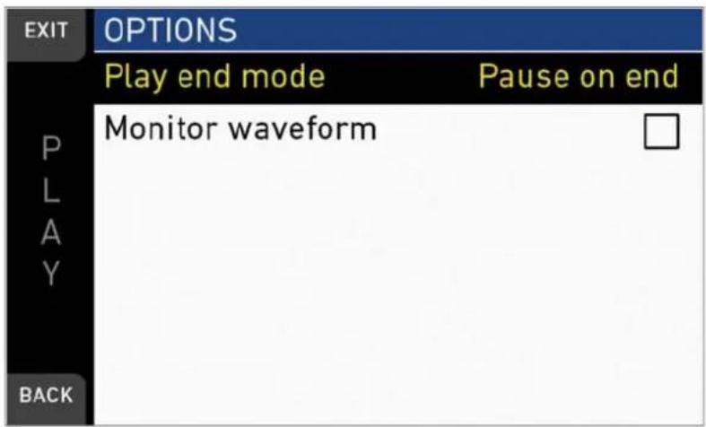
Pressing OPTIONS on the play screen allows you to modify the playback behaviour.
Play end mode: Sets the playback behavior at the end of a clip:
- Pause on end: Playback pauses at the end of this clip.
- Pause on start: Playback pauses at the beginning of this clip.
- Loop: Playback continues from the beginning of the same clip again.
- Play next clip: Playback continues with the next clip in the cliplist.
- Exit playback: Camera exits playback.
Monitor waveform: Sets the waveform overlay on monitor to On or Off.
10.3 Diopter adjustment
natural_image
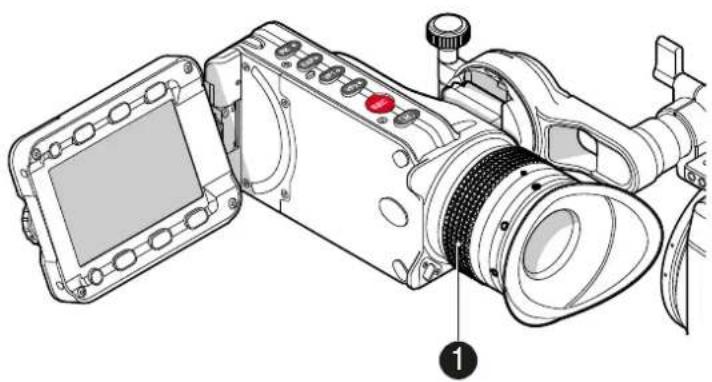
Technical line drawing of a digital camera with labeled parts (no text or symbols present)▶ Twist the ring left or right for diopter adjustment (1).
10.4 Adjusting the monitor
1
natural_image
Technical illustration of a camera module with no visible text or symbols3
natural_image
Illustration of a digital camera module with a magnified inset showing internal components (no text or symbols)2
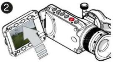
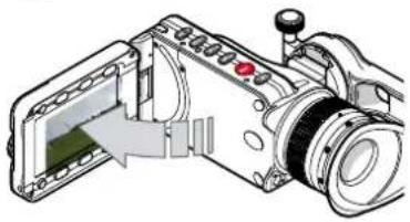
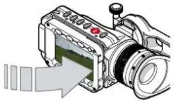
▶ Fold (1), swivel (2) and flip (3) the monitor according to your needs.
10.5 Changing the monitor mode
natural_image
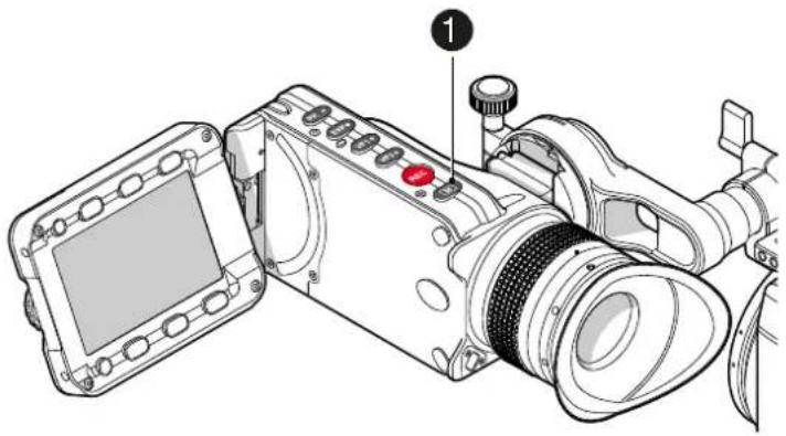
Technical line drawing of a digital camera with labeled parts (no text or symbols present)- To change the monitor mode between live view and user interface: Press M (1).
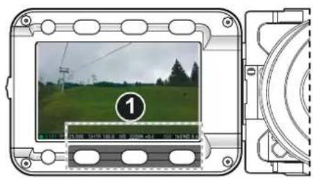
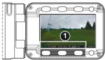
- In live mode, toggle the status bar content (1) via the lower buttons.
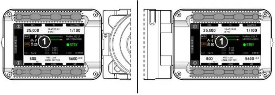
- Via Menu > Monitoring > EVF/Monitor > Settings > Monitor flip mode, you can disable the location sensor that automatically flips the user interface to match a left- or right-sided monitor position (3).
10.6 Live monitor
Below the camera live image, the live screen shows image and camera status. You can toggle the bar's content via the left or right oval button below. The center oval button returns you to the main status bar.
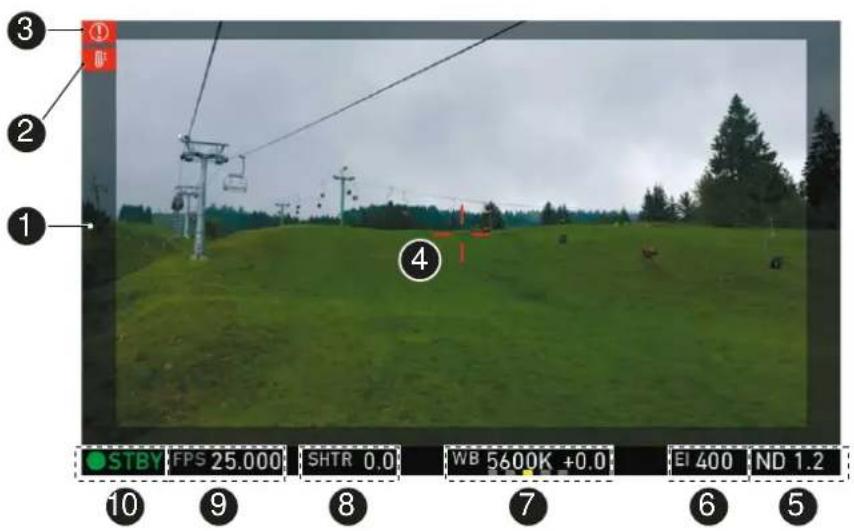
1 Surround mask 6 Exposure index
2 Camera temperature warning (warning=red) 7 White balance
3 ALERT message 8 Shutter value (° or sec)
4 Center mark 9 Sensor frame rate
5 Active ND filter 10 Camera status (here: Standby)
natural_image
Silhouettes of two pine trees against a cloudy sky (no text or symbols)Surround mask
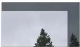
This grayed-out frame marks all non-recorded parts of the sensor image. Can be deactivated.
If surround view is active, the non-recorded area is masked. Style options are: Black line, colored line, or semitransparent mask (as shown here).
natural_image
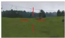
Landscape photo of a grassy field with trees and utility poles, no visible text or symbolsCenter mark
Marks the image center. Can be set to Off, Cross, Dot or Small Dot.
10.7 User monitor
Screen buttons and jogwheel
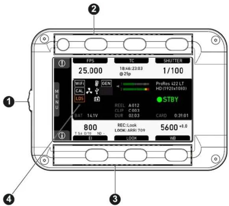
There are eight screen buttons, four above (2) and four below (3) the display (4). Their function depends on the screen content (4) and is labeled directly above or below each button.
Unlabeled buttons have no function for that screen. A grayed-out label means: function currently not available. Via jogwheel (1), you can:
- Scroll or navigate through lists and menus.
- Change values (by scrolling up or down).
- Confirm settings (by pressing the wheel).
On the home screen (4), pressing the jogwheel (1) opens the camera menu.
10.8 Adjusting the monitor brightness
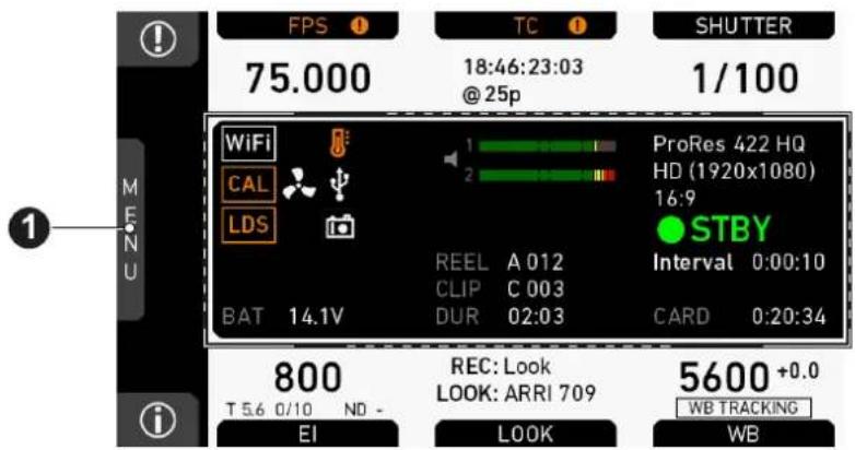
- Open the home screen.
- Via jogwheel (1), open MENU > Monitoring > EVF/Monitor > Settings.
| HOME | SETTINGS | |
| EVF brightness | 8 | |
| M E N U | Monitor brightness | 8 |
| Monitor flip mode | Auto | |
| BACK | ||
- Scroll to Monitor brightness.
- Press the jogwheel.
- Adjust the brightness by scrolling to the required value: 1 (= minimum) to 10 (= maximum).
- Press HOME.
11 Overlay menu
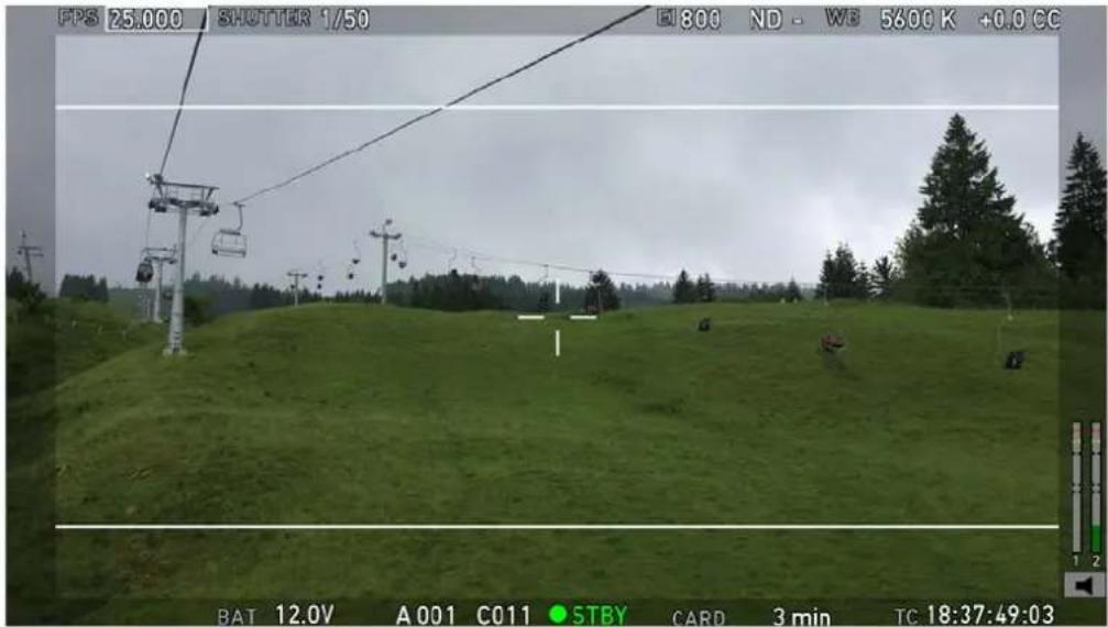
The overlay menu offers a reduced set of camera parameters for adjustment. When activated, it is visible in the top section of the image on the MVF-1 monitor and EVF and on any SDI output which has SDI processing activated. The overlay menu is a quick way to change the following camera settings:
- Sensor FPS
- Shutter (Shutter Angle / Exposure Time)
- Exposure Index
- ND filter
- White Balance
Sensor FPS, Shutter and White Balance cannot be changed manually, but in the range of their user predefined lists. ND filter is changed instantly and requires no additional confirmation step.
A white frame marks the selected parameter. A yellow font means it is in edit mode and can be changed.
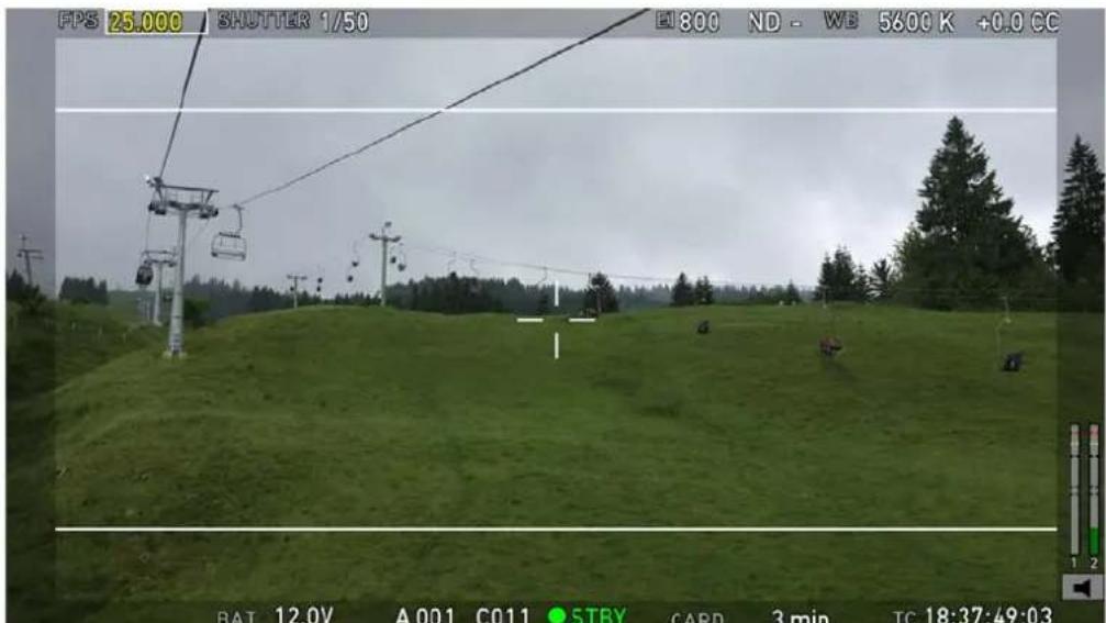
For detailed instructions on how to activate and operate the overlay menu, see the following sections.
Camera buttons
1 Activate the overlay menu by pressing FN + 1.
2 Select a parameter with buttons 1 or 2.
3 Start editing the parameter by pressing button 3.
4 Select the new parameter value with buttons 1 or 2.
5 Confirm the new value by pressing button 3.
6 If required, repeat steps 2-5 for other parameters.
7 Exit the overlay menu by pressing FN + 1.
MVF-1
When the overlay menu is activated, the jogwheel of the MVF-1 can be used to select, edit and confirm parameter changes.
12 Web remote
ALEXA Mini has a web remote function for full remote control of the camera with a web browser. It requires a connection to the camera via WiFi or Ethernet (with ALEXA Ethernet/RJ-45 Cable KC-153-S, K2.72021.0).
By default, WiFi is active. If WiFi is inactive, enable WiFi via the MVF-1, by navigating to MENU>System. Without the MVF-1, the web remote must first be used via a cabled Ethernet connection to enable WiFi.
The web remote has been tested with the following platforms and browsers:
| Desktop browsers Google Chrome 45 | Mozilla Firefox 44 |
| iOS Safari 9.2.1 | |
| Android Google Chrome Mobile 45 |
Open a web browser and enter the URL: http://mini-xxxxx.local (replace xxxxx with the 5-digit serial number of your camera).
NOTICE
To use the web remote function via this URL, the device must support zero-configuration networking (zeroconf), e.g. through Apple Bonjour. Without zeroconf, the webremote can be reached via the IP adress of the network (WiFi or LAN IP). The WiFi IP is fixed to 192.168.153.1. The LAN IP can be either assigned from a DHCP server or configured manually, and can be checked with an MVF-1 via the INFO > Network info screen.
HOME
NETWORK INFO
WiFi IP 192.168.153.1
LAN IP 192.168.0.202
Web remote http://mini-15001.local
BACK
MAIN, PLAY, REC INFO and USER
Web remote is divided into the following four sections:
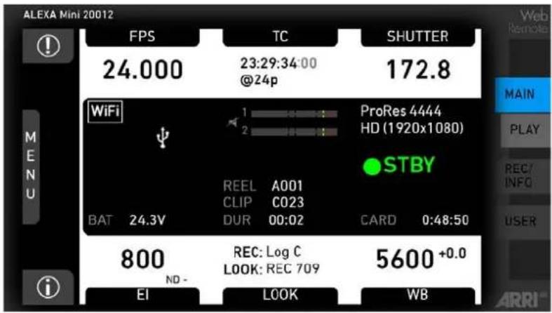
MAIN: Contains the same UI as the camera monitor (no live screen). Click/tap the screen button tabs to enter a screen/trigger a function. Menu items can be clicked/tapped directly.
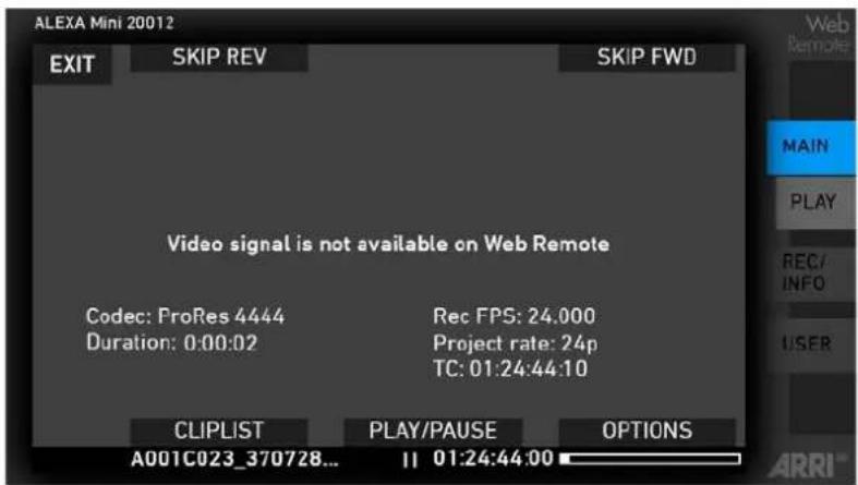
PLAY: Starts playback on the camera. Provides the same controls as the MVF-1, but no video signal.
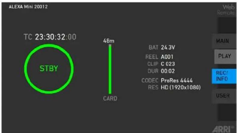
REC INFO: Contains info on the main recording relevant parameters, plus a REC button. Click the big circle icon to start/stop recording.
Note: Rec status may respond with a little delay depending on network speed.
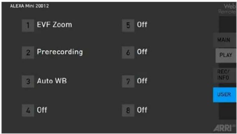
USER: Shows configuration of user buttons and allows to trigger them. Press number icons to trigger user buttons.
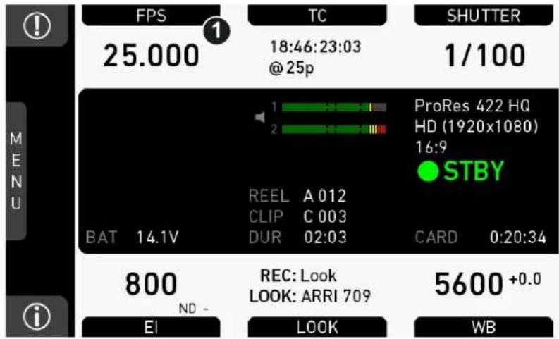
13 Home screen
The home screen gives access to essential camera parameters and statuses. Oval screen buttons and a jogwheel allow quick parameter editing. To return to the home screen from any other screen: Press HOME.
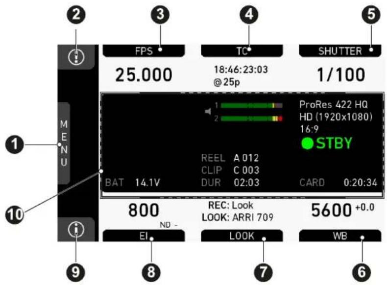
1 MENU jogwheel 6 WB button
2 ALERT message button 7 LOOK button
3 FPS button 8 EI button
4 TC button 9 INFO button
5 SHUTTER button 10 Status section
MENU jogwheel
Press the jogwheel to enter the camera menu.
ALERT message button
If red: Alert messages are available (critical to camera functionality). Press the round button to read them.
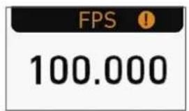
FPS button
FPS shows the sensor frame rate, allowing adjustments from 0.750 to 200.000.
Note: If sensor fps does not match the project rate, the FPS label turns orange and shows an exclamation mark.
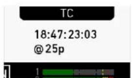
TC button
Shows the current Timecode values and the active project rate, allows adjustment of TC formats and values.
Note: If Timecode is forced to Rec Run, or external TC is missing, the TC label turns orange and shows an exclamation mark. Enter the TC screen by pressing the TC button to see more info on the warning.
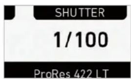
SHUTTER button
Shows shutter settings adjustable either as angle (5.0 to 356.0°) or exposure time (1/25 to 1/8000s).
Shutter angle, sensor rate and exposure time relate as follows: Exp time=Shutter angle/(360*fps). Maximum shutter angle limited by resulting exposure time (1/25s max).
INFO button
Provides access to the camera info screens.
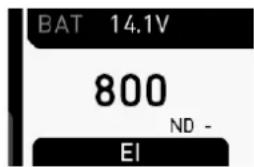
EI button
Shows the current EI rating and active ND filter value. Allows you to set the exposure index in ASA.
Base sensitivity for the ALEXA Mini is 800 ASA. The EI rating can be adjusted from 160 to 3200 ASA.
Note: ASA and ISO ratings are identical.
Via EI>ND, the ND filter can be adjusted.
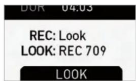
LOOK button
Shows the REC path gamma setting and the name of the active look. Opens the look screen, which provides further access to gamma settings of all image paths and global look.
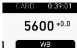
WB button
WB shows the camera's current white balance (= preadjusted color temperature of a light source).
You can adjust WB from 2,000 to 11,000 Kelvin (here: 5,600) in steps of 10 K for red/blue correction.
Also, you can color-compensate for green/magenta tints in a range from -16.0 to +16.0. Positive or negative CC color compensation values then appear in superscript (here: +0.0).
For automatic white balance: Assign Auto WB to a user button and press it twice within one second.
13.1 Status section
The status section on the home screen shows key data on recording, voltage, lockings, etc.:
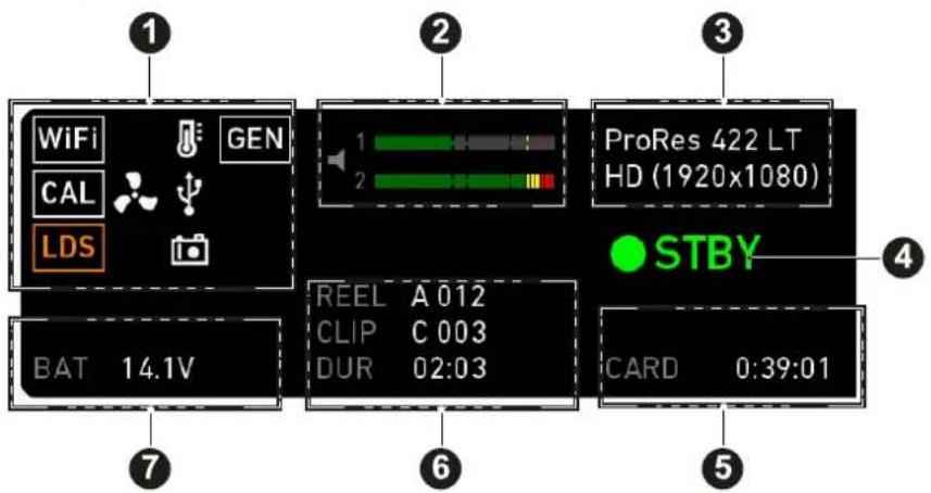
1 Status icons 5 Card status
2 Audio meters 6 Recording status
3 Codec/resolution 7 Battery voltage
4 Camera status
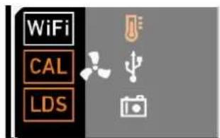
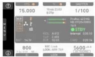
WiFi, CAL and LDS icons
WiFi: Camera WiFi is active.
CAL: Info on lens motor calibration:
- Orange: Lens motor calibration required
- White: Lens motor calibration active
LDS: Indicates an error on the LDS interface.
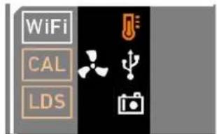
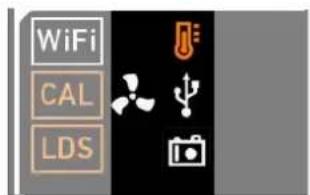
Temperature icon
Alerts on sensor temperature issues:
- Black: Warning
- Orange: Error
- Red: System temperature error (see INFO > System status)
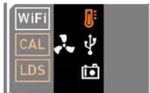
Fan icon
Icon color shows the fan noise status:
- Grey: About to increase above 20 dBa.
• Orange: Higher than 20 dBa.
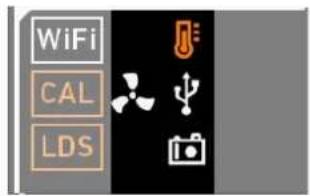
USB icon
Icon color shows USB memory status:
- White: Ready
- Gray: Read only
- Orange: Not usable
Camera icon
White camera icon: Grab is active.
Orange camera icon: Grab failed. Typically cause by missing USB.
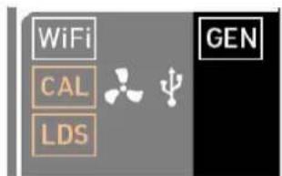
GEN icon
The GEN icon is visible if Genlock is activated via MENU > System > Genlock. Icon color shows the Genlock status.
- White: Genlock active
• Orange: Genlock signal missing
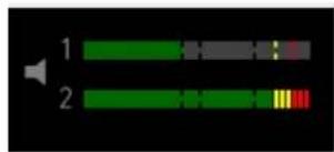
Audio meters
Show current level of camera audio channel signals. If audio is disabled, an icon appears.
Black markers at signal levels -20, -18, -9 dBFS for reference test tone. Yellow marker at -5 dBFS and red marker at -2 dBFS indicate a signal close to clipping. A red frame around the meter indicates a clipping at the A/D stage.
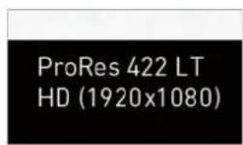
Codec/Resolution
Currently active codec and recording resolution.
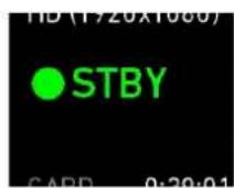
Camera status
STBY: Ready for recording.
REC: Recording.
ERASE: Erasing a CFast 2.0 card. Active erasure disables recording.
None: Recording not possible (e.g. card missing/invalid/full).
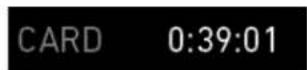
Card status
Remaining capacity of CFast 2.0 card, at current FPS and codec combination in real time.
When card capacity is less than 2 minutes, capacity values starts flashing.
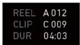
Recording status
REEL: Current reel of active recording medium.
CLIP: Current clip of current reel.
DUR: Duration of currently recorded clip (during REC) or last recorded clip (during STBY).
BAT
Current battery supply level.
13.2 ALERT messages
NOTICE
ALERT messages communicate critical system states to the user. They require immediate action and remain active until the critical state changes back to normal.
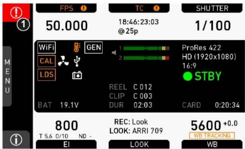
- A red exclamation mark, visible on the homescreen, the monitor, EVF or SDI overlays (if active), indicates available alert state messages.
- On the homescreen, press the button with the exclamation mark (1) to access the pending messages.
- The icon will turn grey when the alert state is no longer valid.
13.3 Info screens
HOME > i
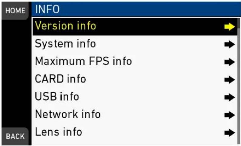
Pressing the [i] button opens the INFO list that offers access to detailed information / subscreens:
- Version info
- System info
• Maximum FPS info - CARD info
- USB info
- Network info
- Lens info
Version info
| HOME | VERSION INFO | |
| Software | 4.0.0 | |
| Revision | 23456 | |
| FPGA (#0) | 12345/12345 | |
| MVF-1 software | 1.0 | |
| Lens mount software | 1.0 | |
| BACK |
Software: Shows the camera software version. The first two parts identify the SUP version.
Revision: Detail info on software version.
FPGA: Firmware version of currently active FPGA (indicated by number in brackets).
MVF-1 software: Software version of MVF-1.
CCP-1 software: Software version of CCP-1 (only shown if connected).
Lens mount software: Software version of lens mount.
System info
| HOME | SYSTEM INFO | |
| Time + Date 2015-09-17 15:30:58 | ||
| Camera serial no. | 20001 | |
| Operating hours | 3:54 | |
| Sensor temperature | 40.0 °C | |
| Sensor temp. state | OK | |
| Camera temp. state | OK | |
| BACK | ||
Time + Date: Current system time and date of camera.
Camera serial no.: Serial number of camera.
Operating hours: Total operational time of camera in hours:minutes.
Sensor temperature: Current temperature of image sensor.
Sensor temp. state: Rates the sensor temperature into the following states: OK, Warning, Error.
Camera temp. state: Rates the camera temperature into the following states: OK, Warning, Error.
Maximum FPS info
| HOME | MAXIMUM FPS INFO | |
| ProRes 4444 @ HD | ||
| Sensor FPS | 200.000 | |
| Codec FPS | 200.000 | |
| CARD FPS | 200.000 | |
| BACK | ||
Sensor FPS: Maximum sensor fps with the current sensor setting of the camera.
Codec FPS: Maximum codec fps with the current codec setting of the camera.
Card FPS: Maximum sensor fps supported by this card with the current codec setting of the camera.
| NOTICE |
| The lowest value determines the maximum selectable fps value. |
Card info
| HOME | CARD INFO | |
| CARD status | Ready | |
| model | SanDisk SDCFSP-120G | |
| SN# | 679952992937443329 | |
| FW version | HDX 8.02 | |
| size | 120 GB | |
| clip count | 5 /400 | |
| BACK | ||
Shows info on the CFAST card.
CARD status: Status of CFAST card.
CARD model: Name of CFAST card model according to manufacturer.
CARD SN#: Serial number of CFAST card.
CARD FW version: Firmware version of CFAST card.
CARD size: Total storage size of card.
CARD clip count: Shows the current number of clips on the card (maximum: 400).
USB info
| HOME | USB INFO | |
| USB status | OK | |
| Storage free/total 3754 / | 8110 MB | |
| Frame line files | 12/100 | |
| License files | 0/100 | |
| Look files | 8/100 | |
| Setup files | 6/100 | |
| BACK | SUP files | 4/20 |
USB Status: Status of USB medium.
Storage free/total: Shows free and total available storage on USB medium in megabyte.
Frame line files: Shows the number of frame line files on the USB medium, and the maximum number of files recognizable by the camera.
License files: Shows the number of license files on the USB medium, and the maximum number of files recognizable by the camera.
Look files: Shows the number of look files on the USB medium, and the maximum number of files recognizable by the camera.
Setup files: Shows the number of user camera setup files on the USB medium, and the maximum number of files recognizable by the camera.
SUP files: Shows the number of SUP (software update package) files on the USB medium, and the maximum number of files recognizable by the camera.
Network info
| HOME | NETWORK INFO | |
| WiFi IP | 192.168.153.1 | |
| LAN IP | 192.168.0.202 | |
| Web remote | http://mini-15001.local | |
| BACK | ||
WiFi IP: IP address of the camera via WiFi.
LAN IP: IP address of the camera via Ethernet.
Web remote: URL address of the camera remote control website.
Lens info
| HOME | LENS INFO | |
| Lens status | LDS lens | |
| Model | Zeiss MP 85 | |
| #SN | 1234 | |
| Focal length | 85mm | |
| Focus | 4.85 m | |
| Iris | T 5.6 0/10 | |
| BACK | ● FOCUS UNIT | |
Lens status: Status/type of lens connected to camera.
Model: Lens model name according to manufacturer.
SN: Serial number of lens.
Focal length: Focal length of lens in mm. May change with a zoom lens.
Focus: Current focus distance value of lens according to user preference setting of distance unit (metric/imperial), which can be changed with the FOCUS UNIT button on the bottom of the screen.
Iris: Current iris value of lens.
User button info
| HOME | USER BUTTON INFO | |
| Button VF1 | EVF+Mon. Zoom | |
| Button VF2 | Prerecording | |
| Button 1 | EVF+Mon. Zoom pos. | |
| Button 2 | Off | |
| Button 3 | Off | |
| Lens RET (n/a) | Off | |
| BACK | ||
Shows functions assigned to user buttons of camera body and MVF-1.
Export HW info file
HW info files may be required by camera service to get detailed info on the hardware details of the camera and its components. After generation, the resulting file will be exported to the USB medium.
Export logfiles
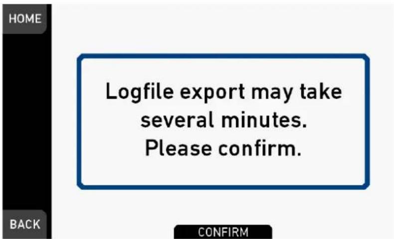
Logfiles help the camera service to analyze problems. Under normal circumstances, logfile export is not required.
Export update logfiles
Similar to normal logfiles, update logfiles help the camera service to analyze problems during the update process. Under normal circumstances, their export is not required.
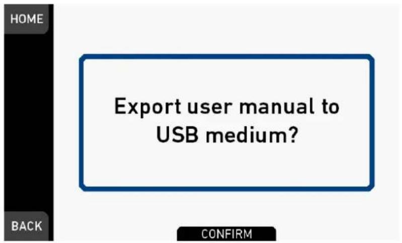
Export user manual
This screen allows to export the camera quick guide and user manual in .pdf format to the USB stick.
13.4 FPS settings
NOTICE
Always use CFast 2.0 cards with maximum write rates. 60-GB cards are slower than 120-GB cards and may limit the fps (depending on the currently set codec).
The maximum possible frame rate may be limited by the set recording codec, recording resolution and CFAST card model. See user manual appendix for a detailed list of fps limits.
13.4.1 Setting/adding an FPS value
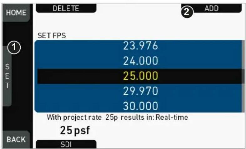
FPS list
bar
| SET FPS | Value | | :--- | :--- | | 1 | 23.976 | | 2 | 24.000 | | 3 | 25.000 | | 4 | 29.970 | | 5 | 30.000 | With project rate: 25p results in: Real-time 25 psf SDI- Via jogwheel (1), scroll to the required value.
- Press the wheel (1) to activate the value.
▶ If the value is not listed: Press ADD (2).
Note: ADD is disabled on reaching the maximum number of 16 list entries.
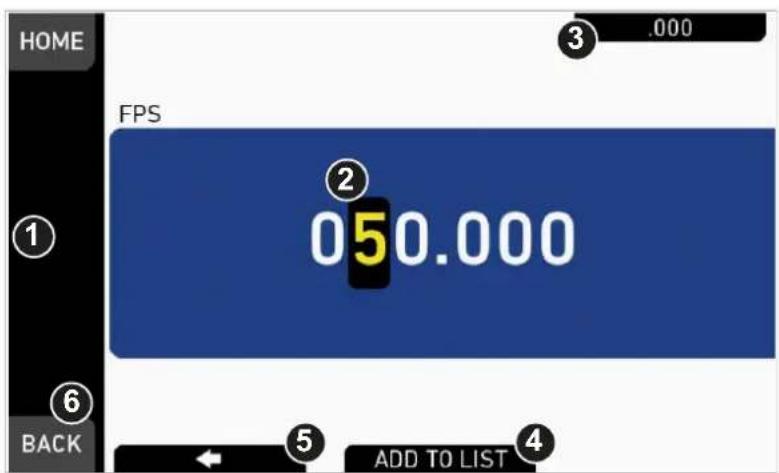
- Upon pressing ADD, an editor opens.
- Create a value with the jogwheel (1):
o Scroll up or down to increase/decrease.
o Press the wheel to select the next digit (2).
- For the previous digit: Press ARROW (5).
o To zero the decimals: Press the ZERO button (3).
- Press ADD TO LIST (4) to save the changes. Cancel with BACK (6).
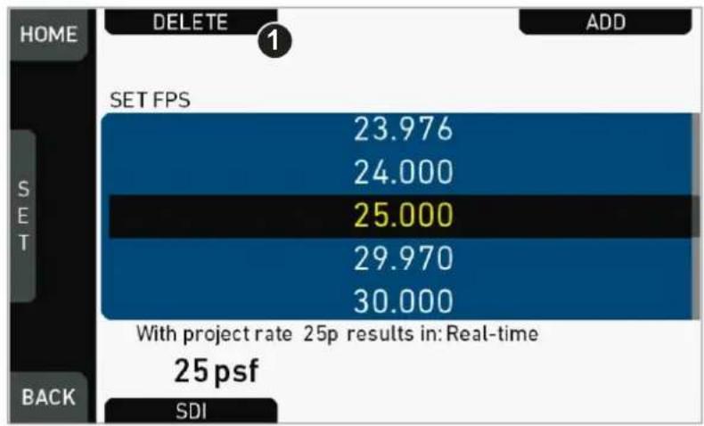
13.4.2 Deleting an FPS value
bar
| SET FPS | Value | | :--- | :--- | | 23.976 | 23.976 | | 24.000 | 24.000 | | 25.000 | 25.000 | | 29.970 | 29.970 | | 30.000 | 30.000 | With project rate 25p results in: Real-time 25 psf SDI- Open the FPS list.
- Press DELETE (1).
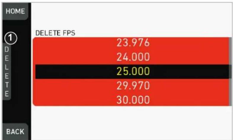
bar
| Category | Delete FPS | |---|---| | HOME | 23.976 | | DELETE | 24.000 | | BACK | 25.000 | | HOME | 29.970 | | DELETE | 30.000 |- The list turns red.
- Via jogwheel (1), select the obsolete entry.
- Note: You cannot select a currently active value.
- Press DELETE (2).
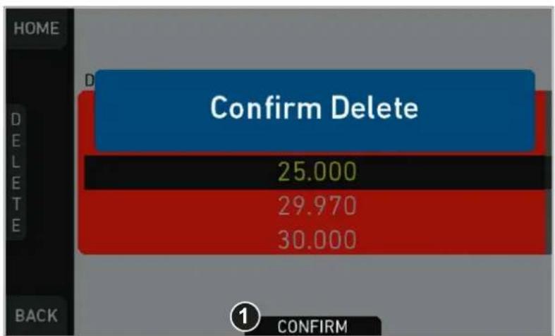
bar
| Category | Value | |---|---| | Confirm Delete | 25.000 | | Confirm Delete | 29.970 | | Confirm Delete | 30.000 |- Press CONFIRM (1). Cancel with BACK.
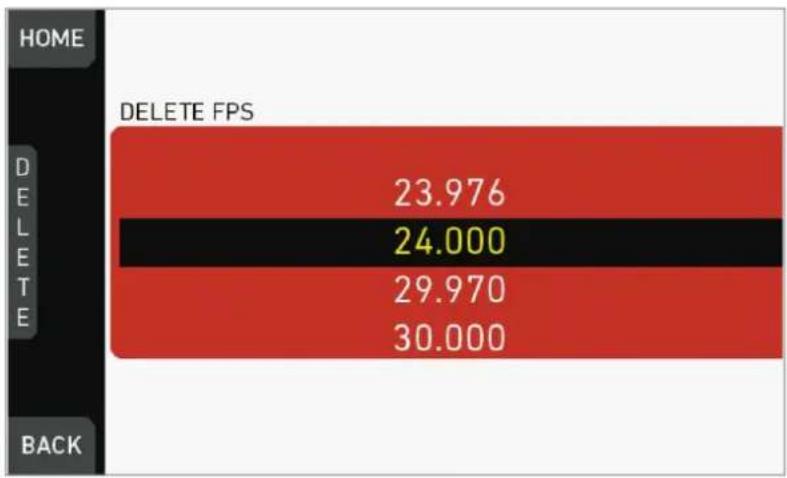
bar
| Category | Delete FPS | |---|---| | HOME | 23.976 | | DELETE | 24.000 | | BACK | 29.970 | | DELETE | 30.000 |- The entry is deleted.
13.5 TC settings
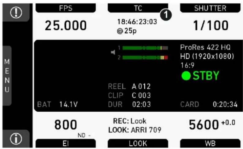
- Press TC (1) on the home screen.
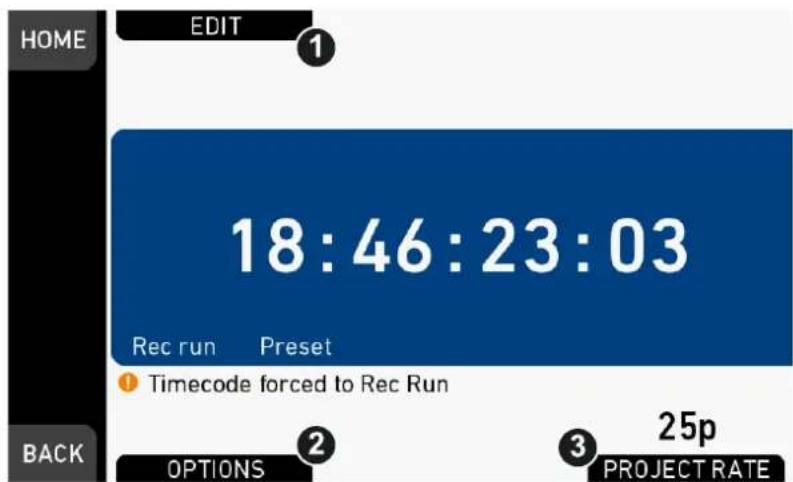
- Current timecode and project rate show up.
- To change the active format: Press OPTIONS (2).
- To change the project rate via the recording menu: Press PROJECT RATE (3).
- Press EDIT (1) to change the current timecode value.
- Note: EDIT (1) is available only when timecode is not in Regen mode.
o Disable Regen via OPTIONS > Mode > Preset (2).
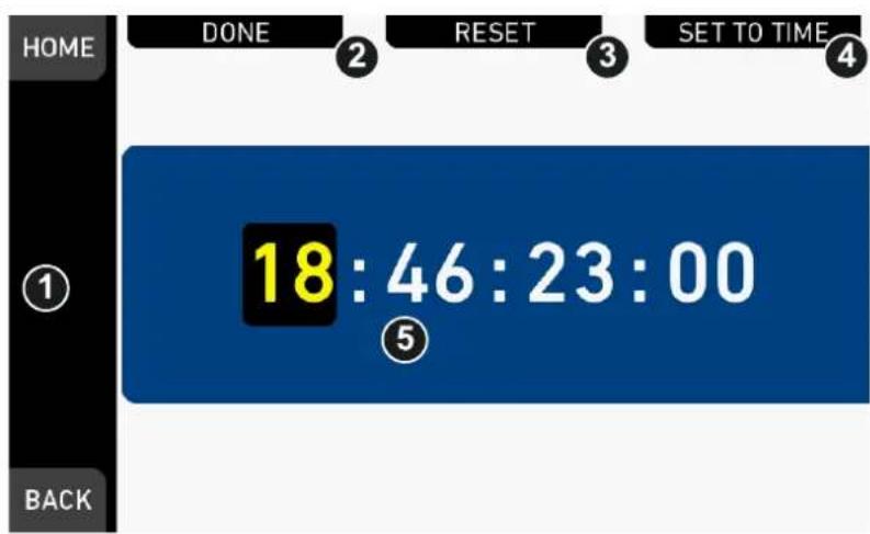
- For TC = 00:00:00:00: Press RESET (3).
- For TC = current system time: Press SET TO TIME (4).
-
Via jogwheel (1), you can change each value:
o Scroll up or down to increase/decrease.
o Press the wheel to select the next digit pair (5). -
Press DONE (2) to save the changes. Cancel with BACK.
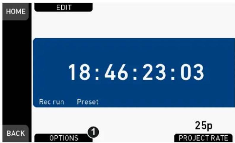
- The Timecode editor closes.
- If applicable: Press OPTIONS (1) to set/change the timecode modes or enable/disable Regen:
TC options
| HOME OPTIONS | |
| Run mode | Rec run |
| Mode | Preset |
| Regen source | Media |
| Count mode | Non-Dropframe |
| TC Offset | +0 |
Run mode
Rec run: Timecode increases during recording only.
Free run: Timecode increases with every new frame. Note: Only possible if sensor fps = project fps. Otherwise, the camera temporarily switches to Rec run.
Mode
Note: You can edit timecode only in Preset mode. The Regen mode disables EDIT.
Preset: The camera uses its internal counter.
Regen: The correct timecode value is regenerated from the active Regen source. Disables the timecode editor.
Regen source
Based on the timecode run mode, the camera determines the Regen source automatically.
Free run regenerates timecode from the timecode input connector.
| NOTICE |
| It is recommended to use LTC with a genlock signal to reduce the risk of timecode drifts. |
| Genlock can either be a Black burst or Tri-level sync signal, or the timecode signal itself. The genlock signal is used to tune the camera clock generator. |
| 1. Make sure sensor fps equals project rate |
| 2. Go to MENU>System>Sensor and set Genlock to the desired source. |
| 3. Connect the genlock source to the camera. |
| 4. If possible, keep genlock source connected to camera. |
| 5. Otherwise, wait for at least 100 frames (about 5 seconds) for genlock signal to tune the camera. |
| 6. Then set MENU>System>Sensor>Genlock to Off and disconnect genlock source from camera. |
Rec run regenerates timecode from the active recording card by continuing seamlessly from the last active value.
Count mode
Sets the preference on how timecode is counted with non-integer project rates: 29.97p, 59.94p, 59.94.
Non-dropframe: Timecode increases with every frame without compensation, resulting in a 1,001 count for 1,000 frames.
Dropframe: Timecode values are dropped with a defined pattern (frame counts 00 and 01 of every minute, except every 10th minute) to re-adjust for the drift. A semicolon between timecode seconds and frames indicates active dropframe timecode.
TC Offset
Adds/substracts an offset to LTC input signals to compensate for timecode offsets in external devices.
13.6 SHUTTER settings
You can select your preferred shutter unit: Shutter angle converts exposure time into the angle of a virtual rotating mirror shutter as in film cameras.
Note: A fixed angle creates varying exposure times with varying frame rates. You can set angles from 5.0 to 356.0 degrees.
Exposure time shows the effective sensor exposure time. With varying frame rates, it remains identical and can be set from 1/1 to 1/8000 seconds.
Note: Maximum exposure time with a given frame rate is 1/fps, with a limit of 1/1 seconds. For a constant exposure time over a range of used frame rates, set it to 1/(highest used frame rate).
13.6.1 Selecting a SHUTTER unit
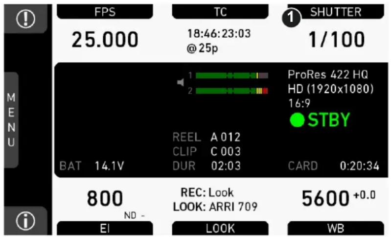
- Press SHUTTER (1) to set the shutter unit:
A list opens (skip forward to "SHUTTER list").
- Press the jogwheel (1) to open the SHUTTER list:
SHUTTER list
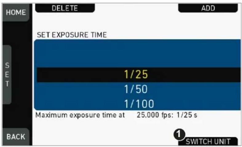
- Press Add (1)
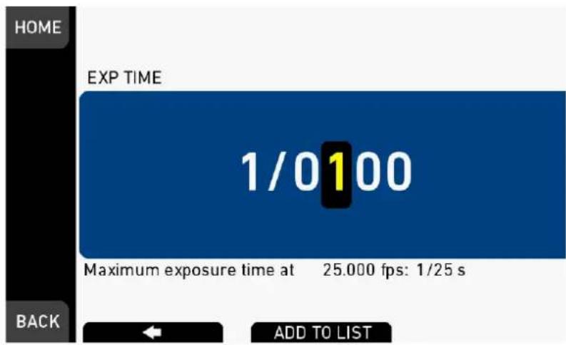
- Adjust exposure time.
- Enter the exposure time by pressing the ADD TO LIST button.
- Press SWITCH UNIT (2).
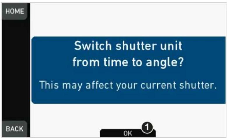
- Confirm with OK (1).
- The camera returns to the home screen.
- The shutter unit has changed (e.g., from time to angle).
Note: How to adjust the shutter for filming a monitor
- Set unit to angle.
- Go to SHUTTER > SELECT > ADD.
- Select the third digit (single degrees).
- Adjust the shutter value until the monitor image flickers the least.
- Select the fourth digit (sub-degrees).
- Fine-adjust the shutter value until there is no more flicker visible.
- Add the shutter value to the list.
13.6.2 Setting/adding a SHUTTER value
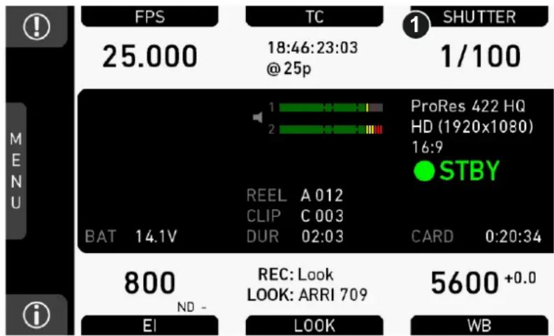
- Press SHUTTER (1) to set the shutter rate:
A list opens (skip forward to "SHUTTER list").
SHUTTER list
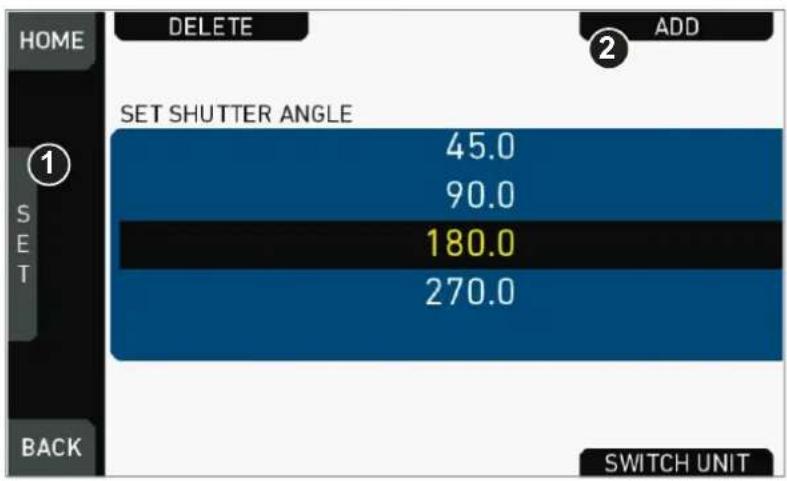
- Via jogwheel (1), scroll to the required value.
- Press the wheel (1) to activate the value.
▶ If the value is not listed: Press ADD (2).
Note: ADD is disabled on reaching the maximum number of 16 list entries.
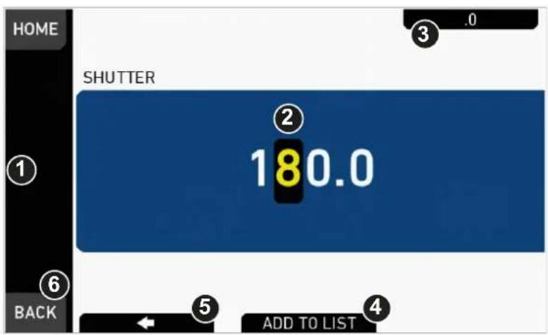
- Upon pressing ADD, an editor opens.
- Create a value with the jogwheel (1):
o Scroll up or down to increase/decrease.
o Press the jogwheel to select the next digit (2).
- For the previous digit: Press ARROW (5).
o To zero the decimals: Press .0 (3).
- Press ADD TO LIST (4) to save the changes. Cancel with BACK (6).
13.6.3 Deleting a SHUTTER value
The shutter value consists of either an angle or exposure time.
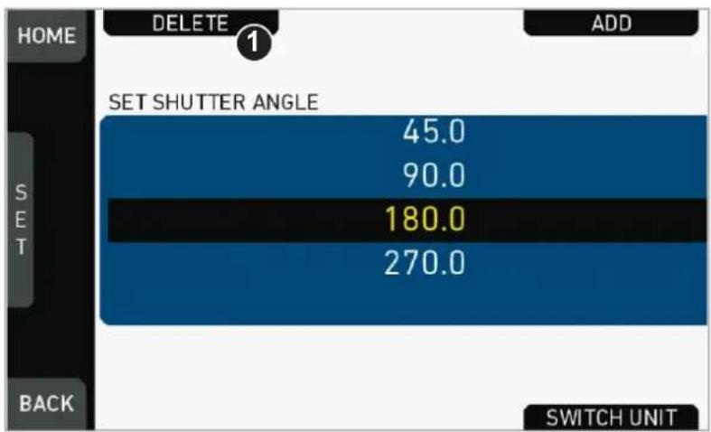
- Open the SHUTTER list (here: angle).
- Press DELETE (1).
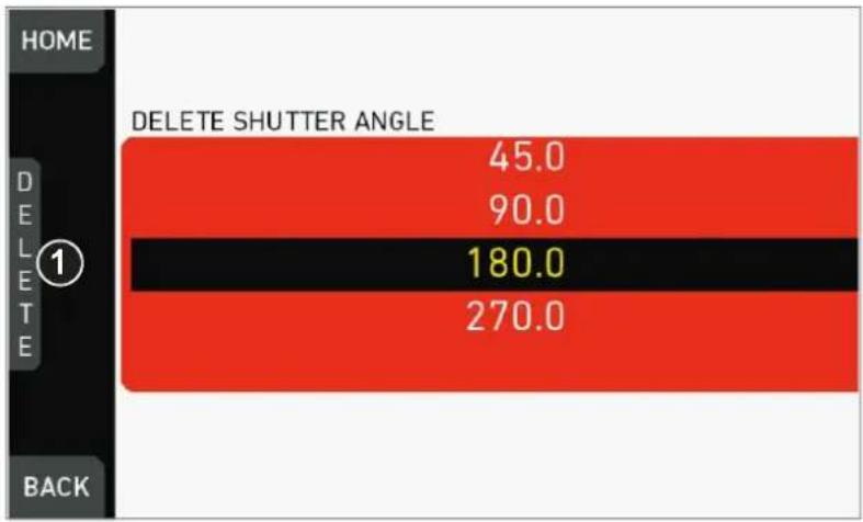
- The list turns red.
- Via jogwheel (1), select the obsolete entry.
- Note: You cannot select a currently active value.
- Press DELETE (2).
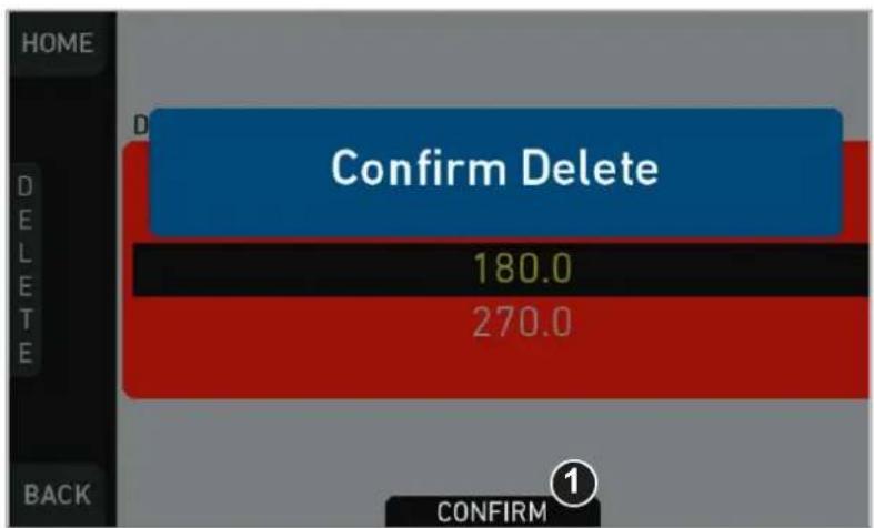
- Press CONFIRM (1). Cancel with BACK.
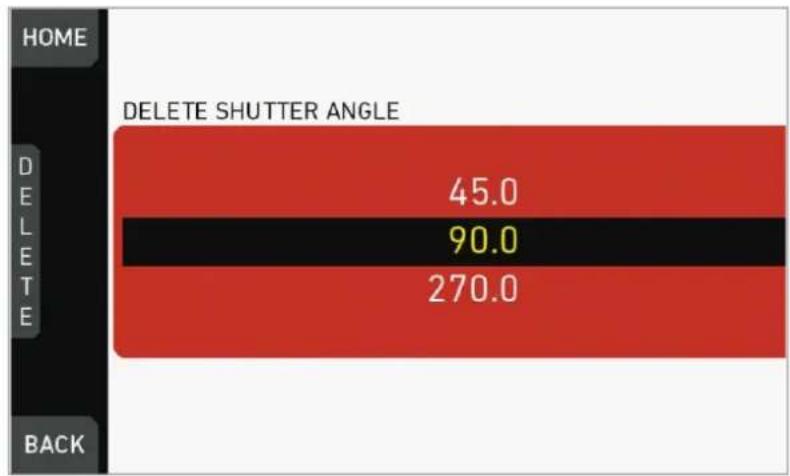
bar
| Category | Delete Shutter Angle | | :--- | :--- | | HOME | 45.0 | | DELETE | 90.0 | | BACK | 270.0 |- The entry is deleted.
13.7 WB settings
13.7.1 Setting/adding a WB value
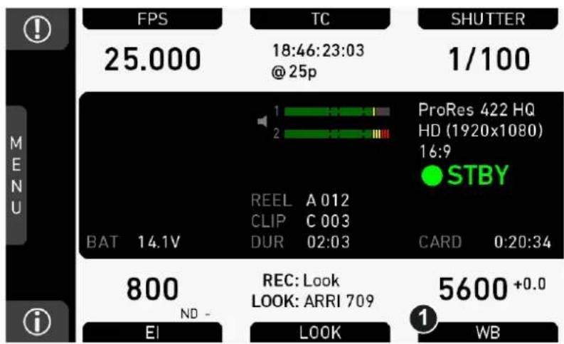
- Press WB (1) on the home screen.
WB list
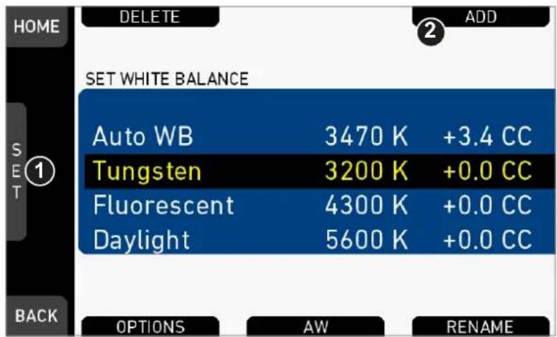
- Via jogwheel (1), scroll to the required value.
- Press the wheel (1) to activate the value.
▶ If the value is not listed: Press ADD (2).
▶ Note: ADD is disabled on reaching the maximum number of 16 list entries.
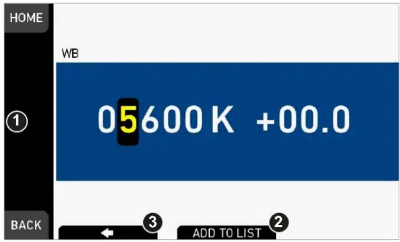
- Upon pressing ADD, an editor opens.
- Create the WB and CC values with the jogwheel (1).
o Scroll up or down to increase/decrease.
o Press the jogwheel to select the next digit.
- Press ADD TO LIST (2) to save the changes. Cancel with BACK.
13.7.2 Renaming a WB value
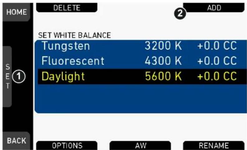
- Open the WB list.
- Via jogwheel (1), scroll to the required file.
- Confirm by pressing the jogwheel.
- Press RENAME (2).
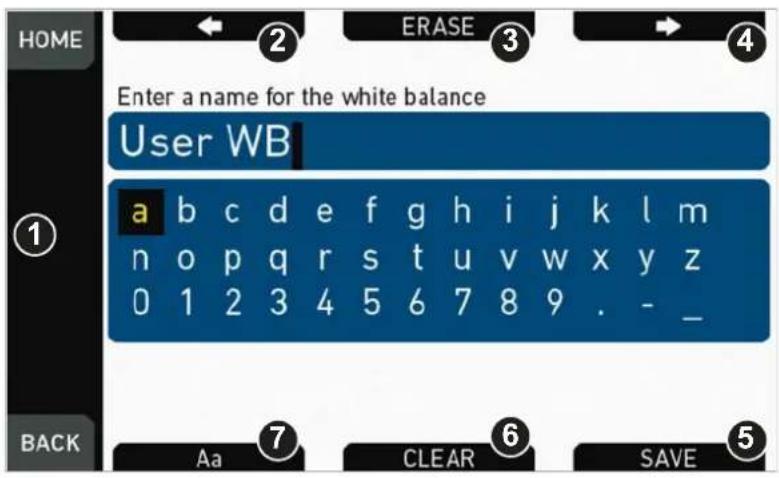
- An editor opens:
o Aa (7) toggles between upper/lower case.
o ERASE (3) deletes the selected character.
o ARROW buttons move the cursor back (2) and forth (4).
- Via jogwheel (1), select/confirm characters to form a name.
- Press SAVE (5) when complete.
- Note: Saving a file with an already existing name is not allowed.
- You can also CLEAR (6) an entire string/name.
13.7.3 Deleting a WB value
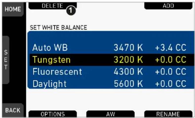
- Open the WB list.
- Press DELETE (1).
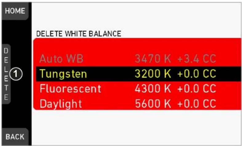
- The list turns red.
- Via jogwheel (1), select the obsolete entry.
- Note: You cannot select a currently active value.
- Press DELETE (2).
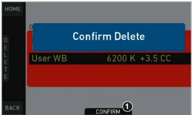
- Press CONFIRM (1). Cancel with BACK.
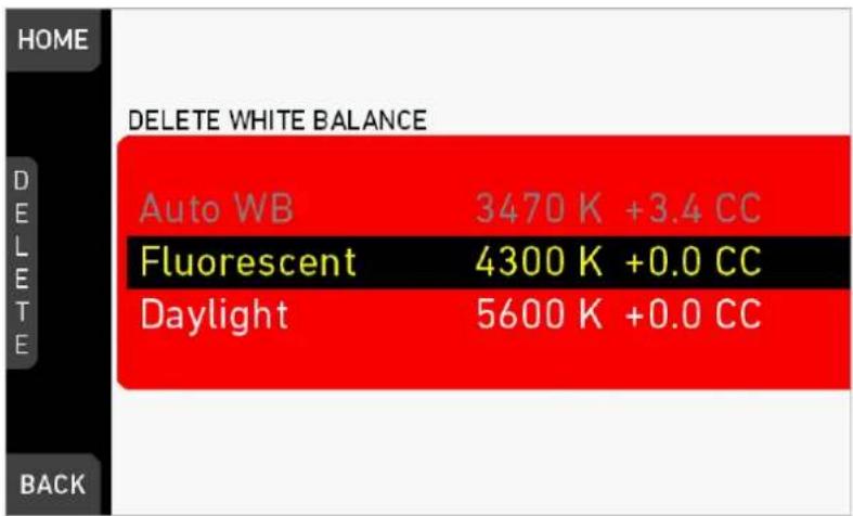
- The entry is deleted.
13.7.4 WB Options
Auto WB mode: Sets the calculation method of auto white balance. Matrix analyzes the full image and uses the image part best suited for WB calculation, while Center uses the image center area only.
WB tracking: Activates the automatic white balance tracking, where the white balance value is continuously updated based on the image scene.
Note: WB tracking always uses Matrix mode for WB calculation.
13.8 LOOK and gamma settings
ARRI 709: Renders the video image according to the ITU.R-BT709 standard, for most accurate color reproduction on standard broadcast monitors.
Commercial: Renders the image brighter for smoother skin tones.
Landscape: Applies a steeper contrast curve to the image.
LCC 709: Low Contrast Curve look that keeps more details in highlights for color correction purposes.
Vibrant: Boosts color saturation except for red and yellow (skintone protection).
ALEXA Classic 709: Matches the color reproduction of ALEXA Mini to the ARRI ALEXA.
To create look files for the camera, download the free Mac OS utility ARRI Color Tool from the ARRI website:
https://www.arri.com/camera/amira/tools/arri_color_tool/
13.8.1 Setting the LOOK file
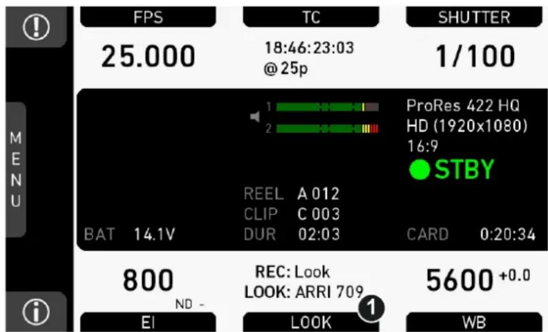
- Press LOOK (1) to set the active look:
A list opens (skip forward to "LOOK list").
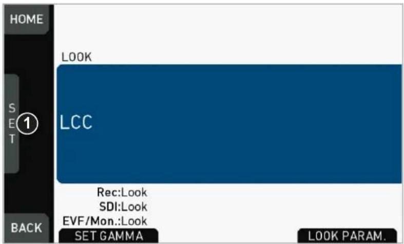
- Press the jogwheel (1).
LOOK list
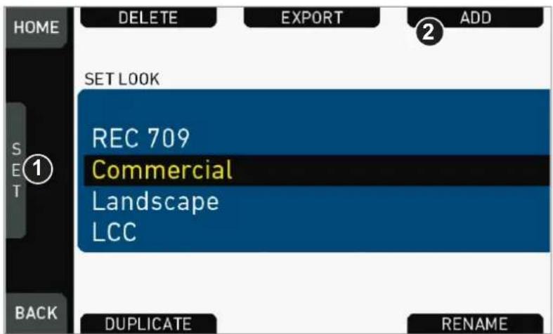
- Via jogwheel (1), scroll to the required look.
- Press the jogwheel (1) to activate the look.
o If the look is not listed: Press ADD (2). For details, see page 83.
o Note: ADD is disabled on reaching the maximum number of list entries.
- Cancel with BACK.
- The required look is now active.
13.8.2 Setting Gamma
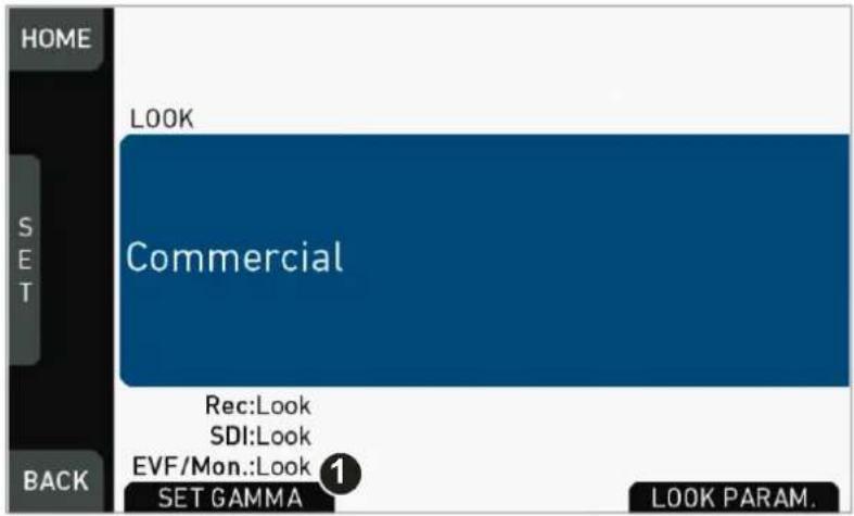
- Open the active look file.
- Press SET GAMMA (1).
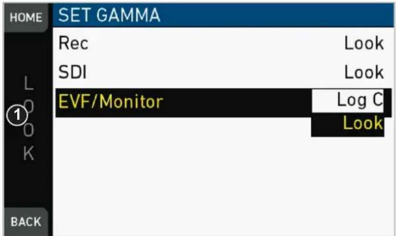
- The gamma settings for the three different image paths appear.
- Via jogwheel (1), select and confirm the required gamma for each image path.
Log C
Based on the Cineon format for output to film print or digital intermediate, this logarithmic gamma requires color-grading in postproduction.
On standard broadcast monitors, LOG C images appear flat and desaturated. Proper display, dailies and editing proxies require a conversion look-up table (LUT).
Create preview LUTs with the ARRI LUT Generator at www.arridigital.com.
LOOK
Applies a video display gamma to camera images. The default ARRI 709 look complies with the ITU.R-BT709 standard for display on standard broadcast monitors.
13.8.3 Adding a LOOK file
NOTICE
You can add look files either from the camera default look folder or via a USB memory stick.
Look files are copied from the USB to the camera. If you remove the memory stick, the installed look files remain accessible.
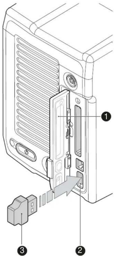
- Save all look files to be added on a properly prepared USB memory stick, in the folder /ARRI/A-MINI/LOOKFILES.
- Open the media lid (1).
- Connect the USB memory (3) to the camera (2).
HOME > LOOK > SET LOOK
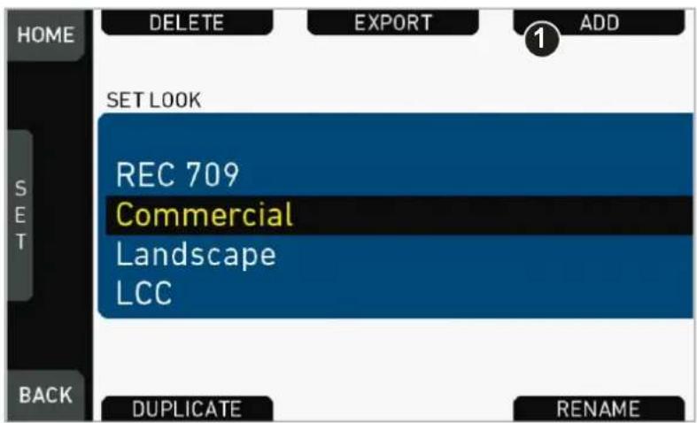
- Open the list of installed looks.
- Press ADD (1).
- Note: ADD is inactive/gray if the maximum number of looks (20) is installed.
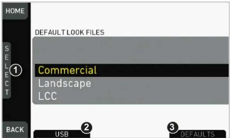
- A list of default look files appears.
- If sufficiently licensed: Press USB (2) or DEFAULTS (3) to select a file source:
o DEFAULTS: ARRI default look files delivered with the camera.
o USB: User look files on the camera USB stick.

- Via jogwheel (1), scroll to the required file.
- Confirm by pressing the jogwheel (1).
- Note: Use unique file names to avoid possible overwritings. For details on file naming, see page 89.
- Repeat for other look files if required.
13.8.4 Deleting a LOOK file
NOTICE
User-defined look files are deleted irreversibly. For loss prevention and future re-installation, always export user-defined look files to a USB memory stick before deletion. Default looks are re-installable without prior export.
HOME > LOOK > SET LOOK

- Open the list of installed looks.
- Note: REC 709 is pre-installed and non-deletable.
- Press DELETE (1).
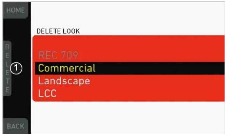
- The list turns red.
- Via jogwheel (1), select the obsolete entry.
- Press DELETE (2).
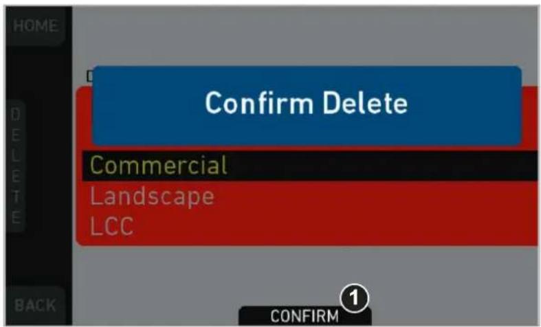
- Press CONFIRM (1). Cancel with BACK.
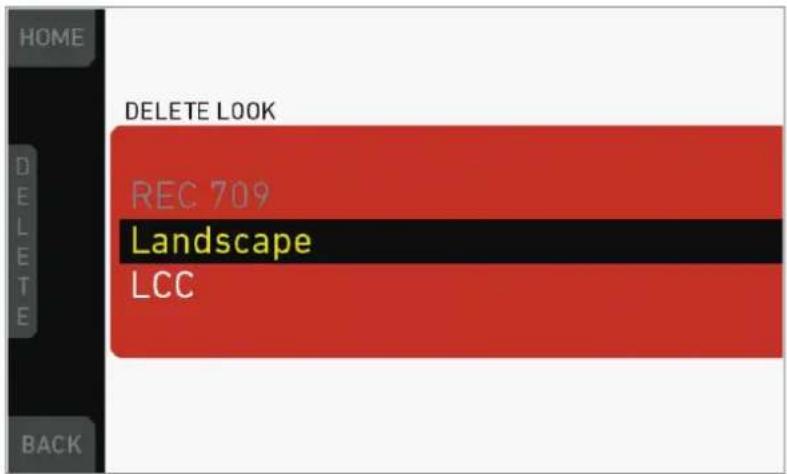
- The entry is deleted.
13.8.5 Exporting a LOOK file
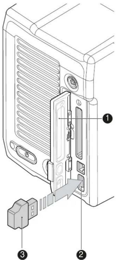
- Properly prepare a USB memory stick.
- Open the media lid (1).
- Connect the USB memory (3) to the camera (2).
HOME > LOOK > SET LOOK
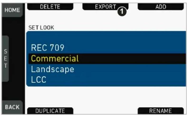
- Open the list of installed looks.
- Press EXPORT (1).
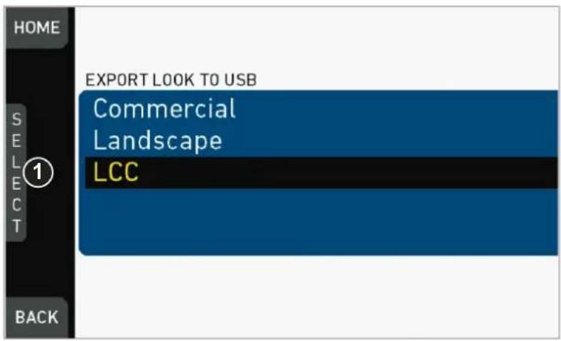
- An export list appears.
- Via jogwheel (1), scroll to the file for export.
- Confirm by pressing the jogwheel (1).
- Note: Rename a file to avoid possible overwritings. For file naming, see page 89.
13.8.6 Duplicating/renaming a LOOK file
NOTICE
By duplication you can create a new look based on an existing one. For a new look from scratch, duplicate REC 709 and edit its parameters. Except for REC 709, you can rename all look files.
HOME > LOOK > SET LOOK
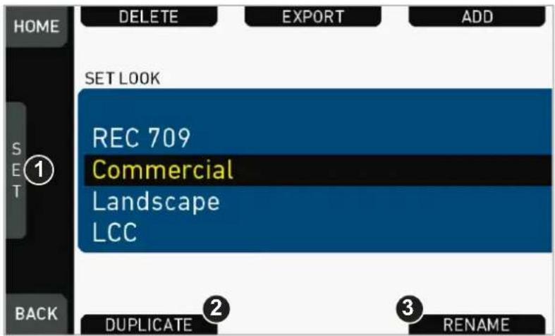
- Open the list of installed looks.
- Via jogwheel (1), scroll to the required file.
- Confirm by pressing the jogwheel.
- Press DUPLICATE (2) and/or RENAME (3).
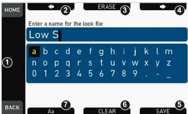
- An editor opens:
o Aa (7) toggles between upper/lower case.
- ERASE (3) deletes the selected character.
o ARROW buttons move the cursor back (2) and forth (4).
- Via jogwheel (1), select/confirm characters to form a name.
- Press SAVE (5) when complete.
- Note: Saving a file with an already existing name is not allowed.
- You can also CLEAR (6) an entire string/name.
13.8.7 LOOK parameters
NOTICE
A look file contains different parameters for image alterations.
User-defined looks may contain a non-editable 3D LUT instead of video parameters.
HOME > LOOK > SET LOOK > SET PARAM.
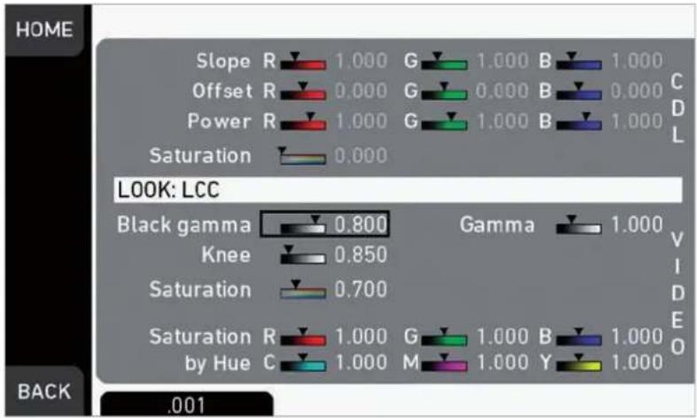
Slope, Offset, Power, Saturation affect ASC CDL images under Log C.
Black Gamma, Gamma, Knee, Saturation, Saturation by Hue affect VIDEO images.
ASC CDL parameters are applied to the image before VIDEO parameters. Please refer to the ARRI white paper on color parameters (for download at www.arri.com).
Note: All look transforms, including ASC CDL, are applied in the conversion from Log C to Video color space. When you choose Log C as gamma for an image path, the clean Log C image is routed to this path.
13.8.7.1 ASC CDL Transforms
The American Society of Cinematographers has specified a set of transforms that have become a standard in postproduction. They are determined by slope, offset, power and saturation (applied in that order).
All these parameters are based on simple color manipulations (multiplying with a factor, adding an offset, raising to an exponent). Noted as "Color Decision List" (ASC CDL), they offer an exchange format for basic look transformations between color correction systems and editing tools by different manufacturers.
The ALEXA Mini image processing applies ASC CDL transforms to the Log C encoded image. This allows manipulations such as exposure correction or bringing down highlights, before the picture is converted to the display color space with its steeper contrast curve.
Slope
The linear section of the Log C curve is equivalent to the gamma of a negative film stock. The Log C curve has a default gamma of approximately 0.51 (adjustable via slope parameter).
A slope value of 1.2 will have a similar effect as using negative stock with a gamma of 0.6 (= 1.2 * 0.5). A value below 1.0 will lower the gamma accordingly.
Offset
This most intuitive CDL parameter has a similar effect as increasing the exposure index on the camera. If you are familiar with the motion picture print film process, it's the same as printer lights.
Power
Via power you can adjust the mid tones, similar to the Gamma parameter in video color grading. A power value below 1.0 will increase, a value above 1.0 will decrease the mid tone brightness.
(Log) Saturation
This parameter affects the saturation of all color components in the Log domain. A value of 1.0 represents the default saturation.
13.8.7.2 3D LUT and video look parameters
Via 3D LUT (lookup table), the camera generates a Rec 709 video image from Log C data. Next to the ASC CDL parameters, which apply to the Log C image, the camera also offers a set of video look parameters (VLP) for tone mapping and color transformation of the rendering 3D LUT.
VLPs determine knee, black gamma and the gamma of the tone map curve, which qualify the contrast of the output image. They also include values for saturation and the saturation by hue for six color vectors (green, yellow, red, magenta, blue, cyan).
Knee
The knee parameter controls the transition of mid-tones into highlights. Values below 0.5 (default) produce harder highlights, higher values soften them. Knee is applied to all channels equally (master control). It has no effect on the mid gray level.
Black gamma
The black gamma controls the shadow detail in the image. Values below 0.5 (default) bring down, higher values brighten the blacks. Black gamma is applied as master control. It only affects the mid gray level for very high values.
Gamma
This setting can be used to brighten or darken the mid tones, while leaving the black and white level unchanged. Values below 1.0 (default) will darken; higher values will brighten the image.
(Video) Saturation
The VLP set also includes a saturation control, with a similar effect as the ASC saturation control. A value of 1.0 represents the default saturation.
Saturation by Hue
This parameter set allows you to control the saturation for six color vectors (red, yellow, green, cyan, blue, magenta) independently.
13.8.8 LOOK editing
NOTICE
Editing will overwrite and existing look file and its values. To prevent this, duplicate the look first, and then edit the duplicate. REC 709 cannot be edited.
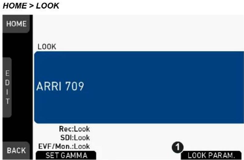
- On home screen, press LOOK (see above)
- Press LOOK PARAM. (1).
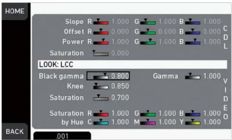
- All look parameters appear.
- For details, see page 90.
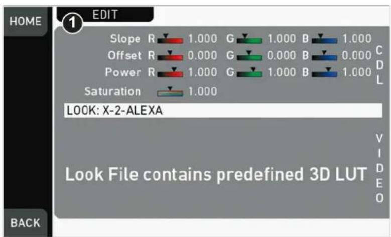
- Look files with a 3D-LUT offer no VIDEO parameters.
- Press EDIT (1).
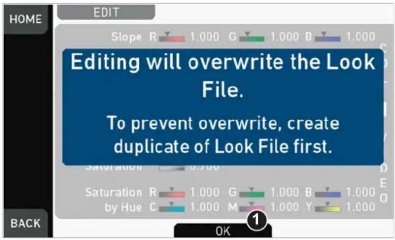
- A warning on file overwriting appears.
- Press OK (1) to close the warning.
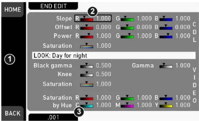
- An editor opens.
- Via jogwheel (1), scroll to the required parameter.
- A black frame (2) marks your selection.
- Pressing the lower right screen button (3) toggles the edit step size between 0.001, 0.01, and 0.1.
- Press the jogwheel (1) to start editing the selected value.
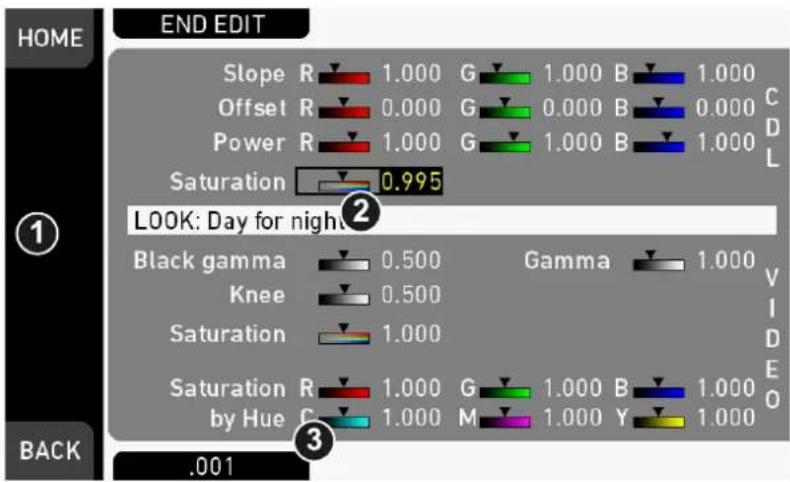
- A yellow-on-black font (3) marks the edit mode.
- Confirm the new value by pressing the jogwheel (1).
- Edit more parameters if required.
- After editing: Press SAVE (2).
- To revert all changes: Press UNDO CHANGES (4).
- Note: Recording while editing will save all changes automatically.
13.9 EI settings
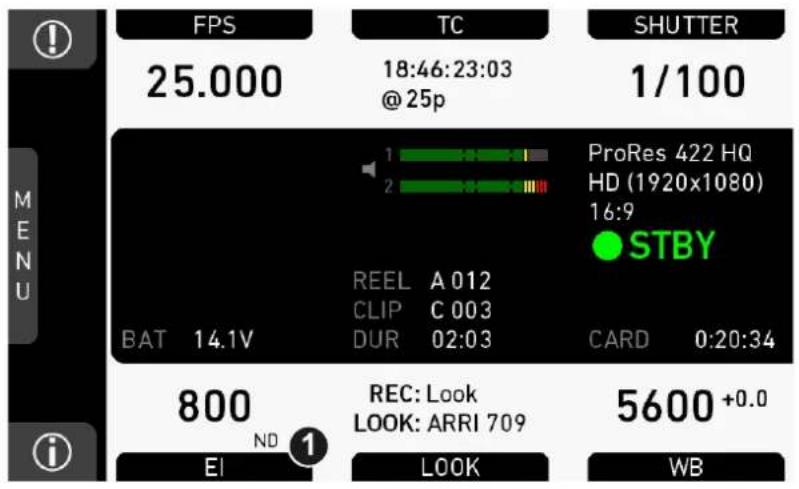
- Press EI (1) on the home screen.
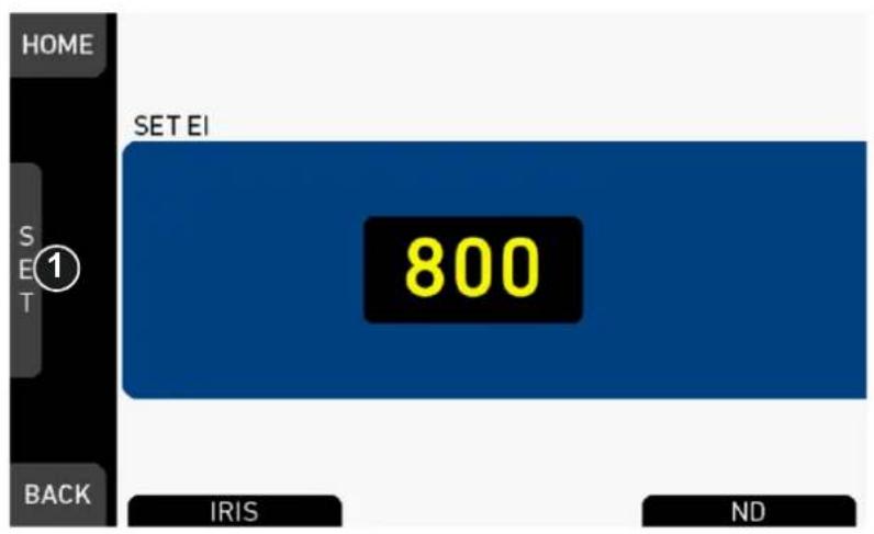
- Select a value with the jogwheel (1):
o Scroll up or down to increase/decrease.
o Press the jogwheel (1) to confirm. Cancel with BACK.
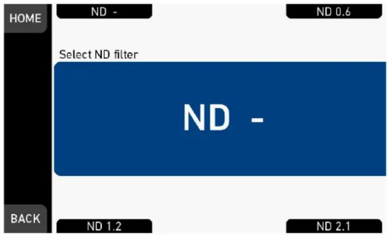
In this screen, the ND filter can be set via screen buttons. No confirmation necessary.
13.9.1 EI technical details
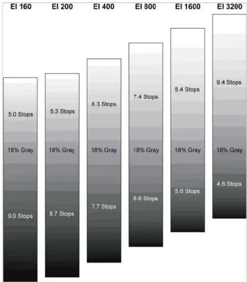
The Exposure Index (EI) is the applied sensitivity of the camera. The ALEXA Mini has a base sensitivity of 800 ASA. This means that the dynamic range is almost evenly distributed above and below neutral gray with low noise in the shadows and clean, smooth clipping behavior in the highlights. Due to its high dynamic range, the ALEXA Mini's sensitivity can be set from 160 to 3200 ASA in steps of 1/3 stops while maintaining high image quality:
EI 160 ^+5.0-9.0 EI 200 ^+5.3-8.7 EI 400 ^+6.3-7.7 EI 800 ^+7.4-6.6 EI 1600 ^+8.4-5.6 EI 3200 ^+9.4-4.6
Applying the exposure indexes at the extremes of the range will nonetheless have an influence on the images.
At low exposure indexes, such as 160 ASA, the dynamic range below neutral gray increases, reducing noise even further. At the same time, the dynamic range above neutral gray is slightly reduced.
Highlight clipping itself is not influenced by this, but the shoulder of the gamma curve will get slightly steeper, reducing the smoothness of the change from almost overexposed to overexposed.
At high exposure indexes, such as 1600 ASA, the images behave in the opposite way. Noise is increased, which makes it important to judge shadow detail, while there will be even more headroom in the highlights:
14 Camera menu
The camera menu on the monitor gives access to all camera functionalities not on the home screen.
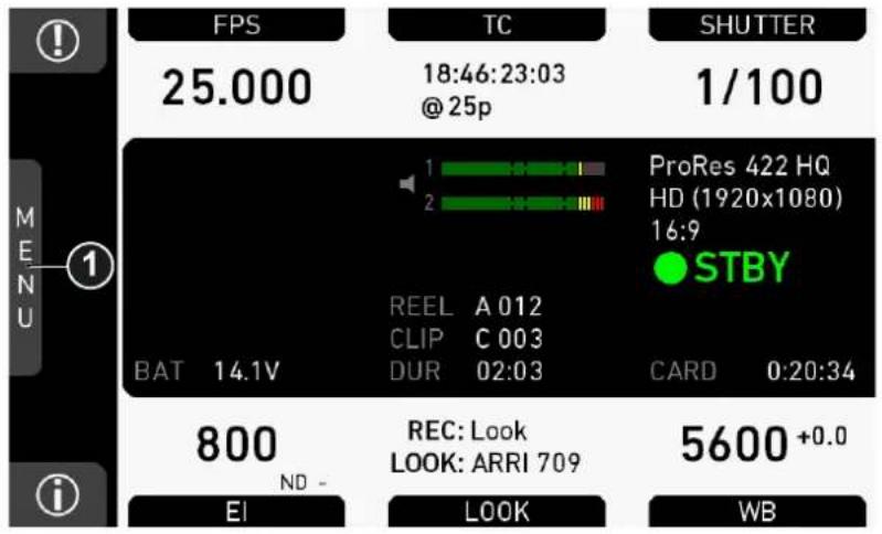
- To access the menu: Press the jogwheel (1) while on the home screen.
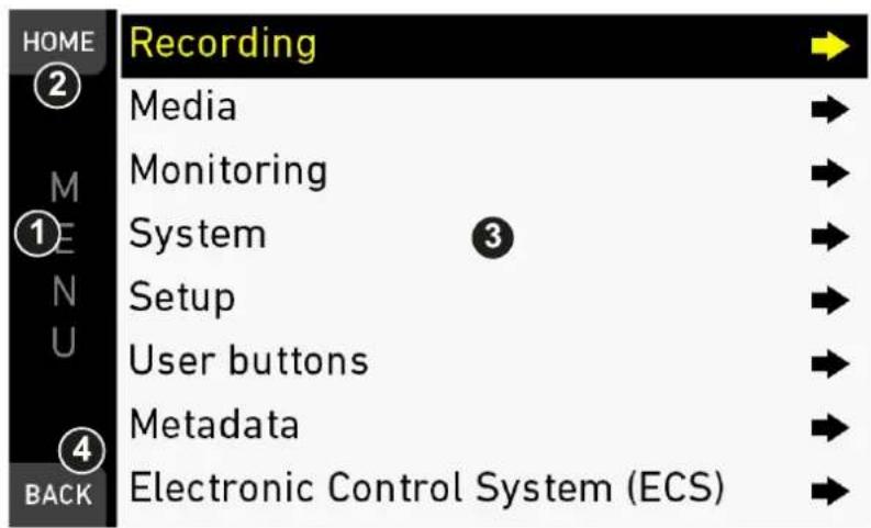
- Via jogwheel (1), scroll up or down to the required entry (3).
- To enter: Press the jogwheel (1).
- Entries with an arrow navigate to a lower menu level.
o To navigate deeper: Press the jogwheel (1).
o To return to a higher menu: Press BACK (4).
-
Entries with a value allow direct editing.
-
To edit a value: Turn the jogwheel (1).
o To confirm and end editing: Press the jogwheel (1). -
To cancel editing: Press BACK (4).
-
To leave the menu: Press HOME (2).
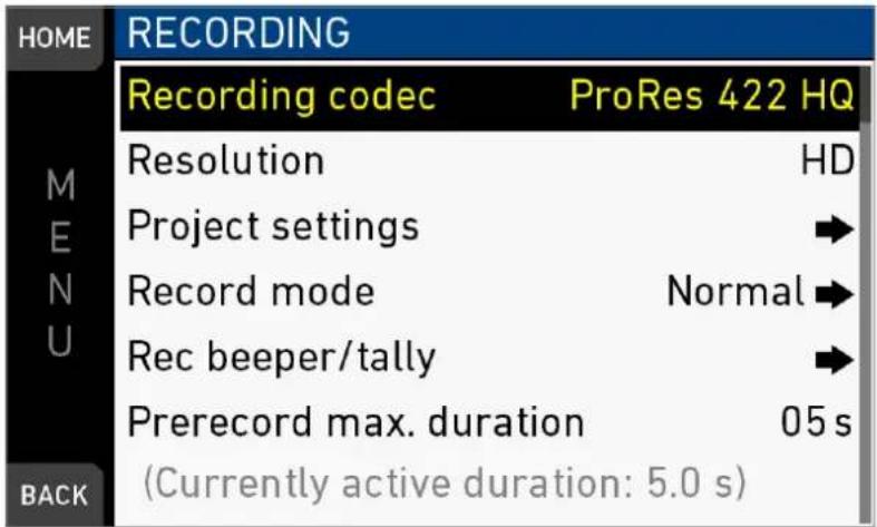
15 MENU > Recording
15.1 Recording Codec
MENU > Recording > Recording codec
Allows you to select one of the following recording codecs:
| Recording codec | Color coding | Bit rate ** |
| ProRes 422 LT | 10 bit YCbCr | 90 Mb/s |
| ProRes 422 | 10 bit YCbCr | 125 Mb/s |
| ProRes 422 HQ | 10 bit YCbCr | 185 Mb/s |
| ProRes 4444 | 12 bit RGB | 280 Mb/s |
| ProRes 4444 XQ | 12 bit RGB | 420 Mb/s |
| ARRIRAW* |
* Requires ARRIRAW license. **24 fps, 1920x1080
Note: When the recording codec family is changed, the camera has to perform a partial software reload.
A popup shows the settings that are affected by the reload and might not be available in the new mode. After confirming the popup, the software is reloaded.
15.1.1 ARRIRAW
ARRIRAW data delivers unencrypted, uncompressed and uncompromised image quality from an ALEXA camera. It offers the highest achievable resolution, the camera's natural color response and great exposure latitude as uncompressed and unprocessed sensor data. ARRIRAW images have only one channel. A color reconstruction algorithm calculates the missing components of each pixel based on the type and position of the array of colored filters (Bayer pattern) on the camera sensor.
ARRIRAW de-bayering is available through the ARRIRAW SDK or custom processing, which is implemented in most of the major post production tools for dailies processing and mastering.
ARRIRAW is used for cinema production, visual effects and high quality TV. It is the best format for creative color correction and visual effects work.
The frames are recorded in an MXF (Material eXchange Format) container. An MXF container file can "wrap" different types of video and audio material along with associated metadata. The internal structure of MXF files is defined by the Operational Patterns (OP).
- The OP1a MXF format packages picture, sound, and metadata in a single file.
- The OP1a is a streaming format, which means that even incomplete files can be played.
- The OP-Atom MXF format places picture and sound into individual MXF files. Audio is written after video.
- The OP1a MXF files are the primary acquisition and archiving format for many broadcasters.
15.2 Resolution
MENU > Recording > Resolution
Toggles between the following recording resolutions:
ProRes:
- S16 HD: records images in 1920x1080 resolution
- HD: records images in 1920x1080 resolution.
- HD Ana.*: records images in 1920x1080 resolution.
- 2K: records images in 2048x1152 resolution.
- 2.39:1 2K Ana.*: records images in 2048x858 resolution.
- 3.2K: records images in 3200x1800 resolution.
- 4K UHD: records images in 3840x2160 resolution.
- 4:3 2.8K*: records images in 2944x2160 resolution.
ARRIRAW**:
- 2.8K: records images in 2880x1620 resolution.
- Open Gate 3.4K*: records images in 3424x2202 resolution.
- 4:3 2.8K (OG 3.4K)*: records images in 3424x2202 resolution.
- 16:9 HD Ana. (OG 3.4K)*: records images in 3424x2202 resolution.
- 2.39:1 2K Ana. (OG 3.4K)*: records images in 3424x2202 resolution.
* requires 4:3 license. ** requires ARRIRAW license.
Note: Changing between resolutions may require a software reload. The reload must be confirmed by the user before it is performed.
A popup shows the settings that are affected by the reload and which might not be available in the new mode. After confirming the popup, the software is reloaded.
S16 HD Resolution
In ProRes codec, the camera can be changed to a recording resolution of S16 HD. This resolution records 1920x1080 image from a 1600x900 sensor pixel count, which allows for using S16 PL mount lenses on the camera.
15.2.1 4:3 Recording
With the additional 4:3 license, the ALEXA Mini allows to record with other sensor aspect ratios than 16:9.
The additional recording resolutions are:
| ProRes HD Ana. | 2.39:1 2K Ana.4:3 2.8K |
| ARRIRAW* Open Gate 3.4K | 4:3 2.8K (OG 3.4K)16:9 HD Ana. (OG 3.4K)2.39:1 2K Ana. (OG 3.4K) |
* Requires additional ARRIRAW license.
The recording resolutions with Ana. in their name are intended for recording with anamorphic lenses with a squeeze factor of 2.0. The respective ProRes resolutions perform a de-squeeze on the recorded material. The respective ARRIRAW resolutions are recorded as-is, only anamorphic de-squeeze is enabled per default on the viewing paths.
Note: While the image resolution for 4:3 2.8K is 2880 x 2160 the recorded resolution is 2944 x 2160. The additional border is due to the ALEXA Mini's ProRes encoder that handles multiples of 128 more efficiently. The remaining 32-pixel boundary left and right to the image is filled with black pixels.
15.3 Project settings
15.3.1 Project rate
| HOME | PROJECT SETTINGS | |
| MENU | Project rate | 25p |
| Next reel count | 002 | |
| Camera index | C | |
| Camera ID prefix | R | |
| BACK | ||
MENU > Recording > Project settings > Project rate
Offers the following options for setting a timecode time base and playback frame rate:
| Project rate | Scan format | Sensor real-time recording |
| 23.976p | Progressive | 23.976 fps |
| 24p | Progressive | 24 fps |
| 25p | Progressive | 25 fps |
| 29.97p | Progressive | 29.97 fps |
| 30p | Progressive | 30 fps |
| 48p | Progressive | 48 fps |
| 50p | Progressive | 50 fps |
| 59.94p | Progressive | 59.94 fps |
| 60p | Progressive | 60 fps |
| 50i | Interlaced | 50 fps |
| 59.94i | Interlaced | 59.94 fps |
| 60i | Interlaced | 60 fps |
NOTICE
Changing the project rate will match the sensor fps setting to the project rate. A popup will inform about this. SDI fps should also be checked when changing the project rate.
NOTICE
Setting the camera to an interlaced project rate requires the sensor to run at an equal frequency to capture real-time images. Therefore, as an example, project rate 50i requires the sensor to be set to 50 fps.
NOTICE
Interlaced project rates are only available in recording resolutions HD and S16 HD.
15.3.2 Next reel count
MENU > Recording > Project settings > Next reel count
Sets the reel number assigned to the next new internal recording medium. A new medium is either a blank card or a card with reels of other ALEXA Mini cameras.
15.3.3 Camera Index
MENU > Recording > Project settings > Camera index
Sets the camera identifier. Identifies the individual camera unit (A, B, C, etc.) in clip and reel names.
15.3.4 Camera ID prefix
MENU > Recording > Project settings > Camera ID prefix
Defines the first character of the Camera ID, currently selectable between L and R. The Camera ID is a Base36 representation of the camera serial number and part of each clip name. It allows you to map each clip to a specific camera.
15.3.5 Lens squeeze factor
MENU > Recording > Project settings > Lens squeeze factor
Sets the lens squeeze factor that is written into the metadata.
Note: Parameter is visible with 4:3 license. Parameter is enabled if camera is in 4:3 or Open Gate recording resolution.
15.4 Record mode
| HOME | RECORD MODE | |
| Record mode | Interval | |
| M | Interval length | 0 h 00 m 10 s |
| E | Burst length | 0005 frames |
| N | Duration mode | Preset |
| U | Recording duration | 00 h 30 m 00 s |
| Resulting clip length | 0 h 00 m 36 s | |
| BACK | Stop motion beeper | |
The record mode determines the way in which the camera records images.
Normal
In record mode Normal, the camera records all adjacent images with the set sensor fps for the duration of the recording.
Interval recording
In record mode Interval recording, the camera captures only short bursts of images after waiting a defined duration (=the interval) during the recording. This mode is used to create a time lapse recording.
Stop motion
In record mode Stop motion, the camera captures only single images after receiving a trigger from a user button during the recording. This mode is often used with motion control systems.
Interval recording parameters
Interval length
The duration the camera waits between every burst of images it captures. Set in hours:minutes:seconds. Maximum interval length is 2:00:00.
Burst length
The number of frames that are captured by the camera for each burst. Maximum number of frames is 2000.
Duration mode
Manual: The recording is started and stopped with the REC button.
Preset: The recording is started with the REC button and runs for the set recording duration. Additionally, it can be stopped with the REC button before the set recording duration has passed.
Recording duration
The duration of the interval recording in real-time after start. Set in hours:minutes:seconds. Maximum recording duration is 99:59:59.
Note: When changing the recording duration, the resulting clip length is automatically updated by the camera.
Note: Only available in duration mode: Preset.
Resulting clip length
The duration of the resulting clip. Set in hours:minutes:seconds.
Note: When changing the resulting clip length, the recording duration is automatically updated by the camera.
Note: Only available in duration mode: Preset.
Stop motion beeper
Activate or deactivate the Stop motion beeper.
Note: Only available in record mode: Stop Motion
15.5 Rec beeper / tally
MENU > Recording > Rec beeper/tally
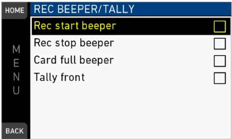
Rec start beeper: Acoustic indication for start of recording.
Rec stop beeper: Acoustic indication for stop of recording.
Card full beeper: Acoustic indication for stop of recording due to full card. Has a different sound pattern than Start/stop beeper for better distinction.
Tally front: Sets the tally light on the viewfinder front end.
Note: On recording, the tally light turns red.
15.6 Pre-recording
NOTICE
Pre-recording requires the assignation of a user button to activate.
Pre-recording buffers images for up to 20 seconds of real-time instead of recording them to the CFast cards.
When pre-recording is activated, pressing REC writes the buffered images to the CFast card. This ensures the capture of unpredictable events without wasting media capacity.
Maximum pre-recording duration is determined by the set combination of sensor fps and recording codec, and can also be limited by the user.
Pressing REC during pre-recording stores all buffered images to the CFast card at maximum write rate. After that, regular recording continues.
Sensor FPS can be changed during prerecording via Home > FPS. This will empty the image buffer at the time of switching, causing the previously buffered images to be lost irreversibly.
15.6.1 How to activate pre-recording
MENU > User buttons > Button VF1 / VF2 > Prerecording
MENU > User buttons > Camera user buttons > Button X > Prerecording
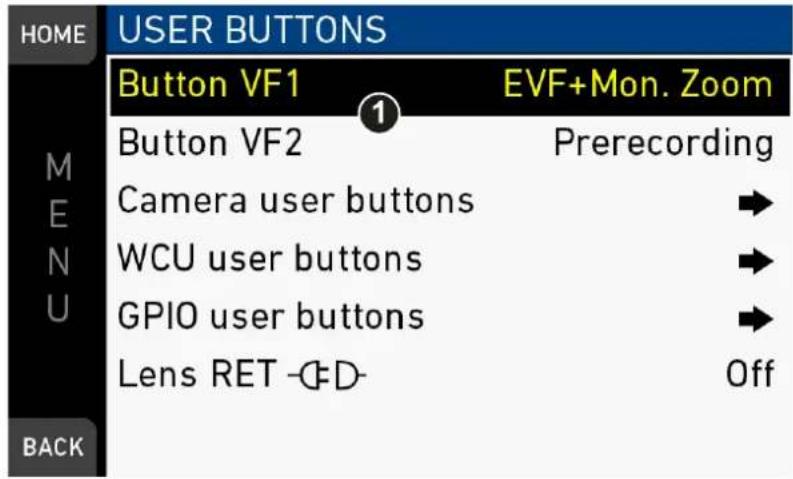
- Assign a user button (1) with the pre-recording functionality, see "User buttons".
- To activate buffering: Press the assigned user button.
- Note: While pre-recording is active, TC, Shutter, Look and MENU settings cannot be accessed. Playback is also not possible. FPS can be changed during pre-recording, but this will clear the image buffer.
- Start/stop recording as usual by pressing a REC button.
- To end buffering: Press the assigned user button again.
- Note: When ending pre-recording, the image buffer is cleared and lost.
15.6.2 Pre-recording maximum duration
MENU > Recording > Prerecord max. duration
Technical limitations may reduce the actual buffer duration below the set value. To activate and de-activate buffering, press the assigned user button.
ProRes 4444 XQ buffer durations
HD 4K UHD
25 fps 9.0 s 2.1 s
29.97 fps 7.5 s 1.7 s
100 fps 2.1 s 0.8 s (at maximum frame rate
of 60 fps)
200 fps 1.8 s (at maximum frame rate
of 120 fps)
ProRes 4444 buffer durations
HD 4K UHD
25 fps 13 s 3.2 s
29.97 fps 11 s 2.7 s
100 fps 3.3 s 1.5 s (at maximum frame rate
of 60 fps)
200 fps 1.6 s -
ProRes 422 HQ/422/422 LT buffer durations
HD 4K UHD
25 fps 20 s 5 / 7.6 / 11 s
29.97 fps 16 s 4.1 / 6.3 / 9.1 s
100 fps 5.0 s 2.0 / 3.1 / 4.5 s (at maximum
frame rate of 60 fps)
200 fps 2.4 s -
15.7 Audio recording
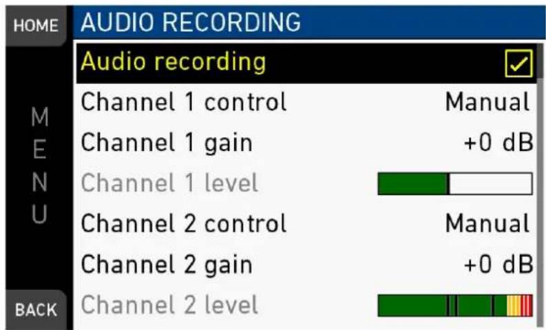
- Audio recording: Sets audio recording On or Off.
- Channel 1/2 control: Sets control mode of channel to Manual, Manual+Limiter or Auto.
- Channel 1/2 gain: Sets gain of channel in Manual and Manual+Limiter control mode between 0 and +30 dB.
- Channel 1/2 level: Shows current level of channel signal in dBFS.
- Test tone Sets 1kHz sine test tone on all channels and outputs to Off, -9 dBFS, -18 dBFS or -20 dBFS.
16 MENU > Media
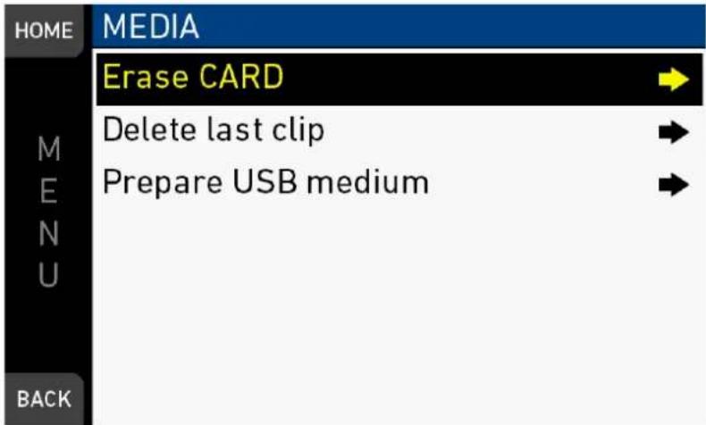
In the media menu, you can erase the CFast card, delete footage, and prepare correct ALEXA folders on USB memory sticks.
16.1 Erase CARD
| NOTICE |
| Irreversibly erases all data from the CFast 2.0 card. Requires prior confirmation. Card ejection during erasure, or interrupting the camera power supply, may render the card unusable. |
MENU > Media > Erase CARD
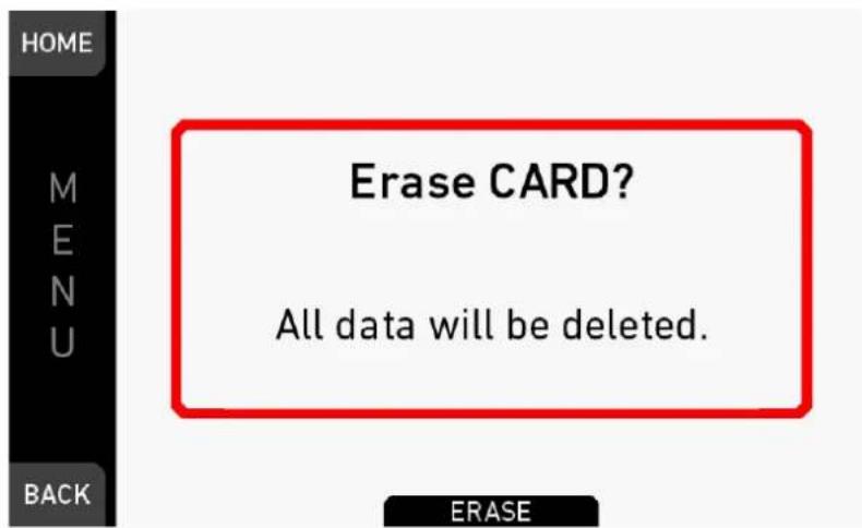
- Via jogwheel, open MENU > Erase CARD.
- A message asks for your confirmation.
- Press ERASE (1).
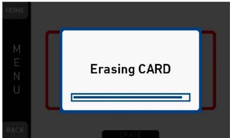
- Wait for card to erase.
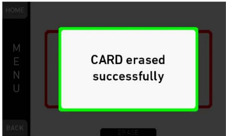
- Successful erasure creates a green message.
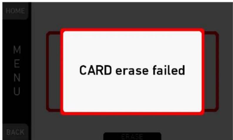
- Failures create a red message.
16.2 Delete last clip
MENU > Media > Delete last clip
Deletes the last recorded (not always the last listed) clip on the CFast 2.0 card. Requires prior confirmation.
Note: On a card recorded with two different cameras, the last recorded clip might be listed in the middle of the clip table.
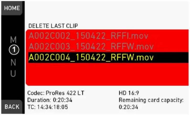
- Via jogwheel, open MENU > Delete last clip.
- Confirm by pressing the jogwheel (1).
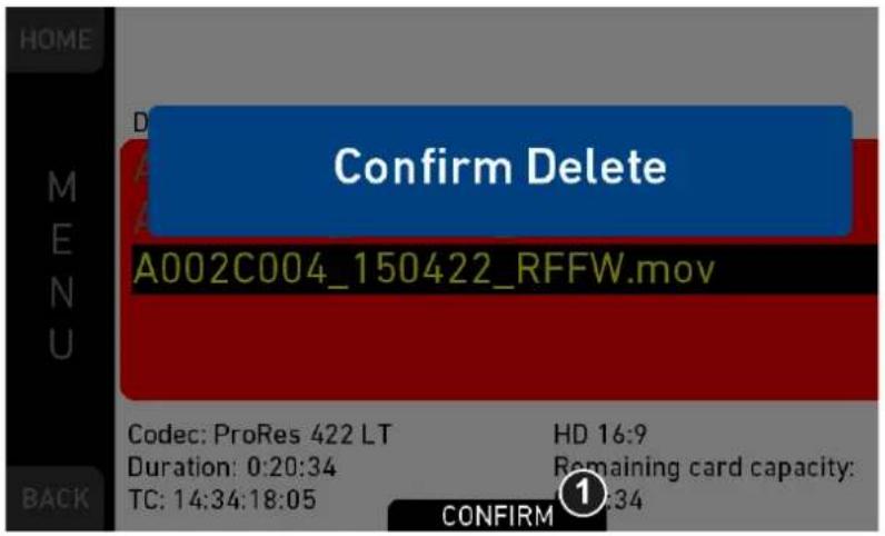
- A message asks for your confirmation.
- Press CONFIRM (1).
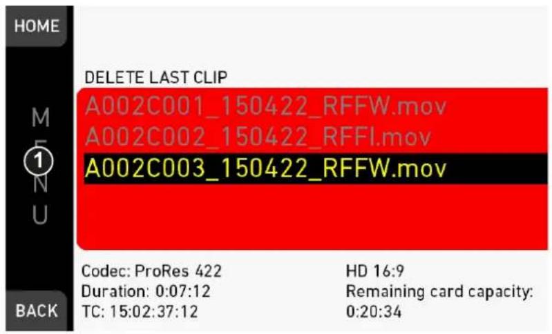
- If required: Delete another clip.
16.3 Prepare USB medium
NOTICE
You can add all user-defined files only from a correctly prepared USB memory stick with a proper folder structure. This action will not alter existing folders and files. Before use with the camera, prepare all USB memory sticks as described in this document.
MENU > Media > Prepare USB medium
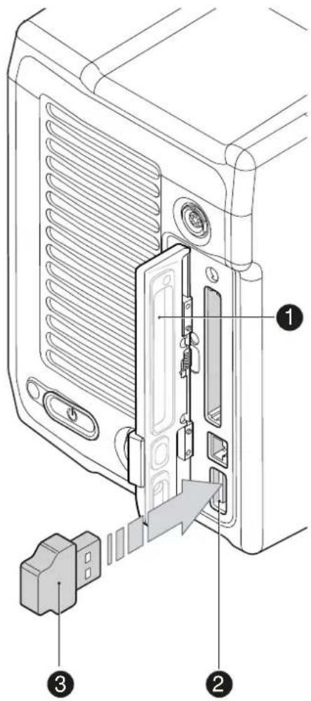
USB memory sticks for the ALEXA Mini must have a specific folder structure which can be created with the camera.
- To prepare a USB memory stick: Open the media lid (1).
- Connect a FAT-formatted USB stick (3) to the camera (2).
- Note: To avoid file corruption, never remove the USB stick during write access.
- Via jogwheel, open MENU > Media > Prepare USB medium.
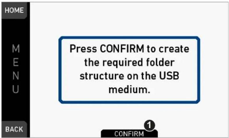
- A message asks for your confirmation.
- Press CONFIRM (1) to create the required ALEXA Mini folder structure:
ARRI / A-MINI / FRAMELINES: for frame line imports to camera
GRABS: for grabbed still frames
LICENSES: for license file installation
LOG: for exported camera and update logfiles
LOOKFILES: for look file imports/exports
MANUAL: for user manual exports from camera
SENSOR: for import/export of User Pixel Mask files and export of framegrabs for UPM creation
SETUPS: for imports/exports of user camera setup files
SUP: for update file installation
17 MENU > Monitoring
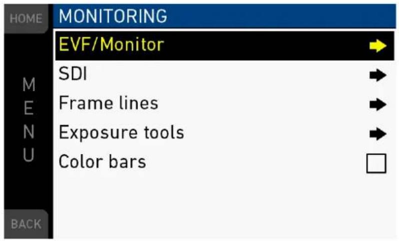
The monitoring menu covers all settings related to EVF, Monitor and SDI, as well as frame lines and other overlays on these outputs.
Color bars: Activates a SMPTE color bar on SDI outputs.
17.1 EVF/Monitor
MENU > Monitoring > EVF/Monitor
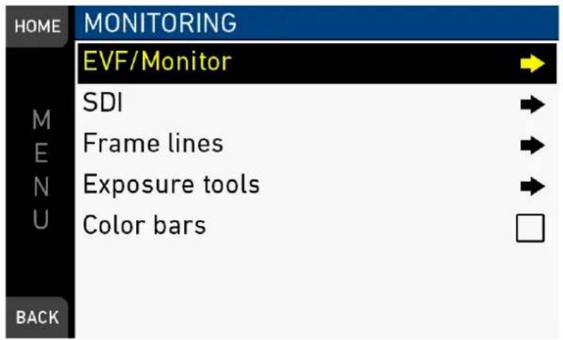
Contains all EVF/monitor tools, settings and overlays: e.g., for exposure/peaking tools, surround masks, anarmorphic desqueeze and zoom positions.
17.1.1 Surround view
MENU > Monitoring > EVF/Monitor > Surround view
Sets the EVF/Monitor surround view on or off. The surround view shows the outer edges of the sensor image which are not recorded. It allows you to spot and avoid unwanted objects before they enter the image.
17.1.2 Zoom position
MENU > Monitoring > EVF/Monitor > Zoom position
Sets the sensor image area to be magnified by zoom. Zoom needs to be activated by a user button.
The camera offers 3x3 patches that can be selected as zoom positions, and an additional position called Eye level, which lies between Top center and Mid center.
While zoom is activated, the zoom position can also be changed by using the wheel or the soft buttons on MVF-1 if it is showing the live image.
17.1.3 Exposure tool
This tool facilitates the evaluation of image exposure. Activation by user button or by pressing EXP on the viewfinder. Note: Zebra is only available on image paths with gamma set to Look.
MENU > Monitoring > Exposure tools
Allows you to select the exposure tool.
False color lays predefined luminance ranges over the viewfinder image.
In Zebra mode, the tool overlays up to two luminance ranges with diagonal stripes. High zebra ranges above, Mid zebra around the user-defined luminance value.
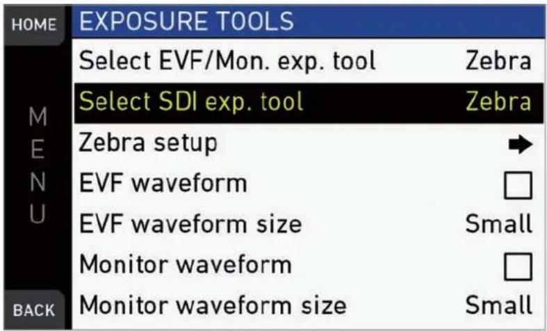
- For a tool change: Scroll to Exp. tool selection.
- Press the jogwheel to toggle between False color and Zebra.
- For zebra options: Open and adjust Zebra setup.
- EVF waveform: Sets waveform overlay on EVF on or off.
- EVF waveform size: Sets size of EVF waveform overlay to small or large.
- Monitor waveform: Sets waveform overlay on monitor on or off.
- Monitor waveform size: Sets size of monitor waveform overlay to small or large.
- Note: Waveform is a luminance waveform from a 0-100% signal level, calculated from the EVF and monitor image signals for each path.
Selecting false color converts the image to black-and-white, and replaces luminances by the following colors:
| Luminance range | Signal level | Color |
| White clipping | 100 to 99 % | Red |
| Just below white clipping | 99 to 97 % | Yellow |
| One stop over medium gray (Caucasian skin) | 56 to 52 % | Pink |
| 18 % medium gray | 42 to 38 % | Green |
| Just above black clipping | 4.0 to 2.5 % | Blue |
| Black clipping | 2.5 to 0.0 % | Purple |
MENU > Monitoring > Exposure tools > Zebra setup
| HOME | ZEBRA SETUP | |
| Zebra mode | High | |
| M | High zebra level | 98% |
| E | High zebra color | Red |
| N | Mid zebra level | 50% |
| U | Mid zebra range | 4% |
| Mid zebra color | White | |
| BACK | ||
Zebra mode: Sets the zebra mode to High, Mid, or both.
High zebra level: Sets the exposure level (in %) above which high zebra is active.
High zebra color: Sets the pattern color.
Mid zebra range: Sets the active range (in %) around a mid zebra level.
Mid zebra color: Sets the pattern color.
17.1.4 Peaking
MENU > Monitoring > EVF/Monitor > Peaking
| HOME | SDI PEAKING | |
| Peaking | ||
| M | Peaking mode | Color |
| E | Peaking level | 01 |
| N | Peaking offset shift | +0 |
| U | Color | Red |
| BACK | ||
Peaking highlights in-focus image sectors for better focus judgement. Activation by user button or by pressing PK on the viewfinder.
Peaking mode: Toggles between color peaking (to overlay in-focus areas with a color), and aperture peaking (to enhance object edges only).
Peaking level: Sets a peaking strength from 1 (= minimum) to 20 (= maximum).
Peaking offset shift: Adjusts the threshold for color peaking to set in, relative to the peaking level.
Note: A negative offset shift (in particular with high ASA ratings) can increase the peaking results.
17.1.5 Settings
MENU > Monitoring > EVF/Monitor > Settings
| HOME | SETTINGS | |
| EVF brightness | 8 | |
| M E N U | Monitor brightness | 8 |
| Monitor flip mode | Auto | |
| BACK | ||
Determines the illumination/orientation of viewfinder and monitor.
EVF brightness: For eyepiece OLED illumination from 1 (= minimum) to 10 (= maximum).
Monitor brightness: For monitor TFT backlight from 1 (= minimum) to 10 (= maximum).
Monitor flip mode: For either Normal, Flipped, or Auto monitor orientation. Auto flips the monitor display automatically via position sensor.
17.1.6 EVF overlays / Monitor overlays / SDI overlays
MENU > Monitoring > EVF/Monitor > Monitor overlays
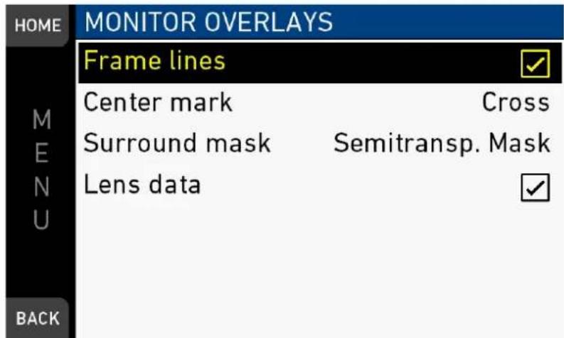
MENU > Monitoring > EVF/Monitor > EVF overlays
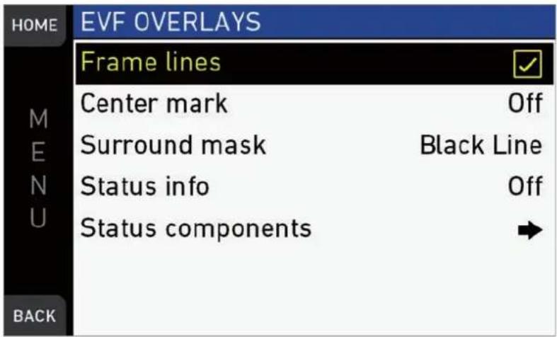
MENU > Monitoring > SDI > SDI processing > Overlays
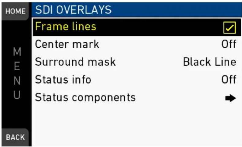
These almost identical menus overlay the monitor, the viewfinder, and the SDI with essential visual tools. Note: The illustration shows the menu for the viewfinder.
Frame lines: Sets frame lines On or Off. Used as a framing reference tool with typically an image frame, a center mark, and aspect ratio.
Center mark: Sets the center mark (for use with frame lines) between Off, Small Dot, Dot, or Cross.
Surround mask: Sets the type of overlay to mark the surround view area of the active image. Either as Black line, Colored line, or semitransparent with 25*, 50 or 75* percent opacity (* only on EVF). The surround view area is used for framing and is not recorded.
Status info: Only for viewfinder and SDI. Sets camera status overlays between Off, Overlay (status on active image), or Safe (status outside of active image).
Note: In Overlay mode, frame lines up to aspect ration 1.94:1 are not displayed because they are covered by the status info.
Status components: Only for viewfinder and SDI. Configures the status info overlay components (see below).
MENU > Monitoring > EVF/Monitor > EVF overlays > EVF status components
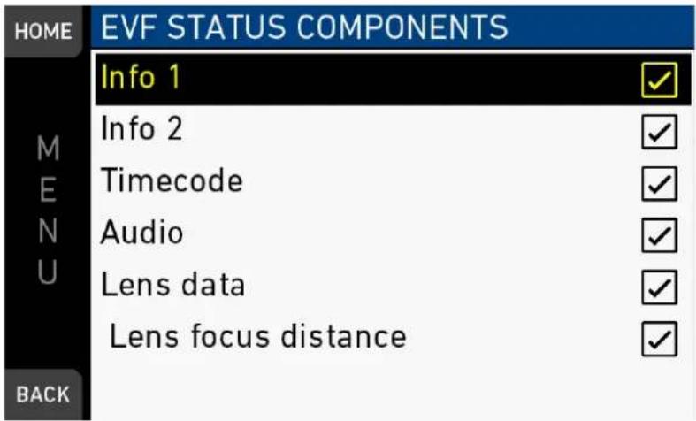
Info 1: Status areas above and below the image.
Info 2: Status areas on left and right side.
Timecode: Current TC in bottom right of status.
Audio: Audio levels, located on lower right side of the status.
Lens data: Focus distance, iris and focal length, if supported by the lens. Also available for monitor (in Monitor overlays menu screen).
Lens focus: Sub-option of lens data setting. Focus distance value of lens, located on the lower image center.
MENU > Monitoring > SDI > SDI processing > Overlays > Status components
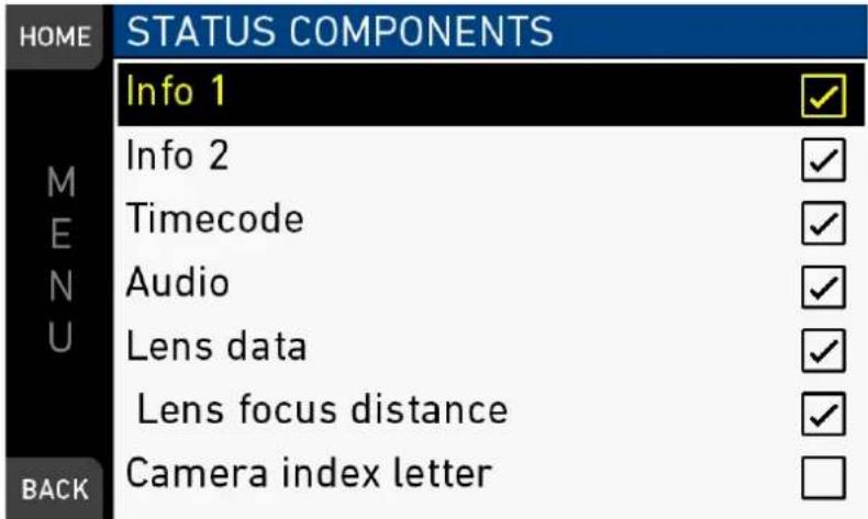
For more information on Status components, see EVF status components.
Camera index letter: Activates the identification of images from different cameras.
17.2 SDI
MENU > Monitoring > SDI
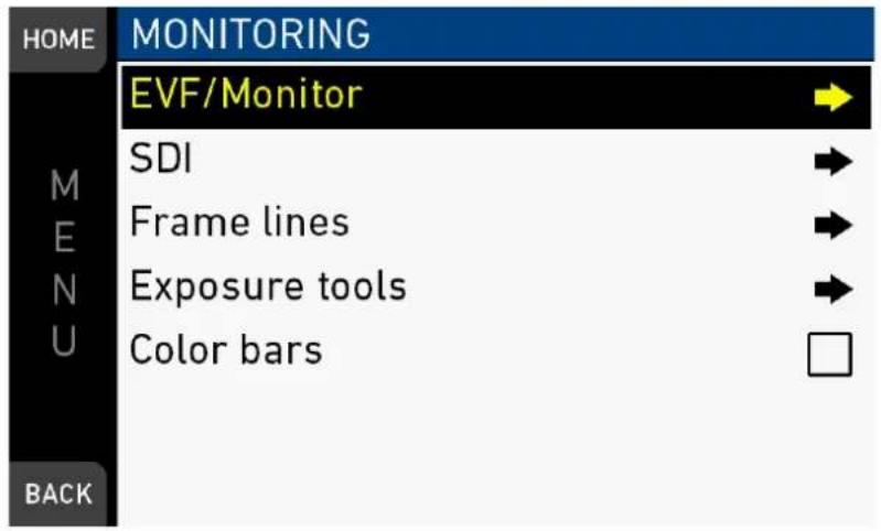
UHD mode: MENU > Monitoring > SDI *
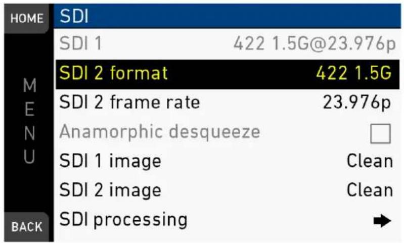
Configures the SDI outputs (based on 1920x1080 image raster).
In 4K UHD and 3.2K modes, SDI 1 and 2 can be configured independently.
In 4K UHD mode:
- When SDI 2 output is configured as 1.5G or 3G, SDI 1 output follows.
- When SDI 2 output is configured as 6G, SDI 1 output is configured as 422 3G
SDI format: Toggles the SDI signal between different formats, sampling structures and color modes:
• 422 1.5G: 4:2:2, YCbCR, 1920x1080
• 422 3G: 4:2:2, YCbCR, 1920x1080
• 444 3G: 4:4:4, RGB, 1920x1080
• 422 6G: 4:2:2, YCbCr, 3840x2160*
*only in 4K UHD mode on SDI 2.
SDI frame rate: Sets the frame rate together with the scan format on the SDI output. If the frame rate is lower than the sensor fps, frame drops will occur. If it is higher, duplicate frames will be output.
The possible scan formats are:
- Progressive (p): Transmits images line by line starting at the top-left pixel
- Progressive segmented frame (psf): Splits progressive images into fields (odd lines and even lines). Transmits these (all odd before all even) line by line
- Interlaced (i): Creates two fields from two adjacent progressive frames (odd lines from the first; even lines from the second frame)
The following combinations of formats, frame rates and scan formats are available:
Format SDI
| 422 1.5G | 23.976p, 24p, 25p, 29.97p, 30p, 50i, 59.94i, 60i, 23.976 psf, 24 pfs, 25psf, 29.97psf, 30psf |
| 422 3G | 48p***, 50p, 59.94p, 60p |
| 444 3G | 24p, 25p, 29.97p, 30p |
| 422 6G** | SDI 1 |
| - | |
| 422 6G** | SDI 2* |
| 23.976p, 24p, 25p, 29.97p, 30p |
* SDI 2 is always clean in 3.2K/4K UHD modes.
** 422 6G is only available in 4K UHD mode on SDI 2. SDI 1 is set automatically to 422 3G with double frame rate of SDI 2. Except when SDI 2 is 23.976p or 24p, then SDI 1 is 50p.
***48p may not be supported by some SDI devices, as this is not a defined frame rate according to the SMPTE standard.
SDI 1/2 image: Sets SDI 1 image to Clean or Processed. Clean image is the recorded image area without further processing. Processed image is enhanced according to the settings of the submenu SDI processing. For SDI 2, the user can choose between Clean and Clone SDI 1. When cloned, SDI has the same image setup as SDI 1.
MENU > Monitoring > SDI > SDI processing
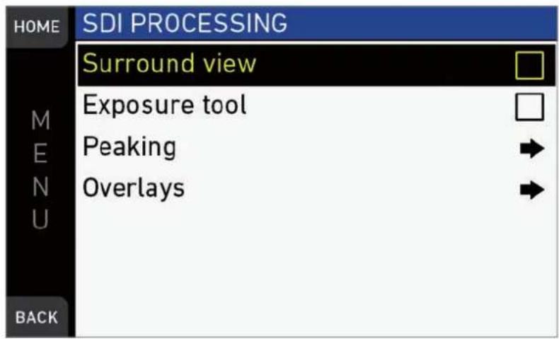
SDI processing: Configures the SDI processing elements.
- Surround view: Sets SDI surround view on or off.
-
Exposure tool: Allows you to select the exposure tool. For more information, see "Exposure tool", page 113.
-
Peaking: Peaking highlights in-focus image sectors for better focus judgement. For more information, see "Peaking", page 114.
- Overlays: Configures graphical overlays of processed SDI out. Almost identical to EVF overlay configuration. For more information, see "EVF overlays / Monitor overlays / SDI overlays", page 115.
MENU > Monitoring > SDI > SDI Processing > Peaking
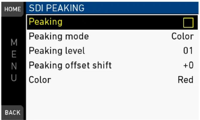
Peaking highlights in-focus image sectors for better focus judgement. Activation by user button or by pressing PK on the viewfinder.
Peaking: Activates Peaking
Peaking mode: Toggles between color peaking (to overlay in-focus areas with a color), and aperture peaking (to enhance object edges only).
Peaking level: Sets a peaking strength from 1 (= minimum) to 20 (= maximum).
Peaking offset shift: Adjusts the threshold for color peaking to set in, relative to the peaking level.
Note: A negative offset shift (in particular with high ASA ratings) can increase the peaking results.
17.3 Frame lines
NOTICE
The camera contains a set of default frame lines with standard aspect ratios. You can also create import external frame lines in XML format.
Try the frame line composer on the ARRI website.
MENU > Monitoring > Frame lines
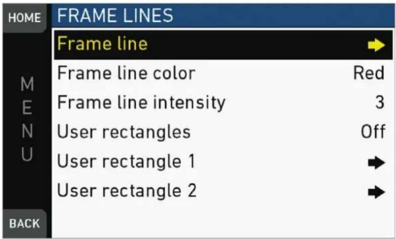
Frame line: Sets the aspect ratio of a frame line.
Frame line color: Sets the color of frame, center mark, user rectangle, surround mask (if mask is set to Colored line).
Frame line intensity: Sets the brightness of frame line components.
User rectangles: Allows you to add two user-defined frame line rectangles.
User rectangle 1 & 2: Configures user rectangle sizes and positions.
17.3.1 Setting/adding a frame line
MENU > Monitoring > Frame lines > Frame line
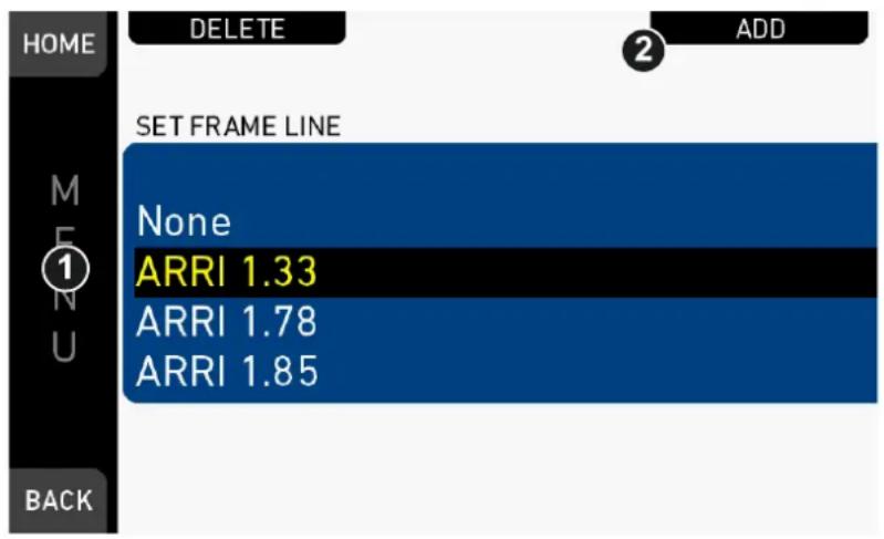
- Via jogwheel, open MENU > Monitoring > Frame lines > Frame line.
- A list of installed frame lines appears.
- Scroll to the required entry (here: ARRI 1.33).
- Confirm by pressing the jogwheel (1).
- If a required entry is not listed: Press ADD (2).
- Note: ADD is inactive/gray if the maximum number of 20 frame lines is installed.
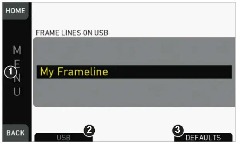
- For internal frame files: Press DEFAULTS (3) to open the default list.
- Via jogwheel (1), scroll to the required file: Press wheel to confirm.
- Repeat for all required files.
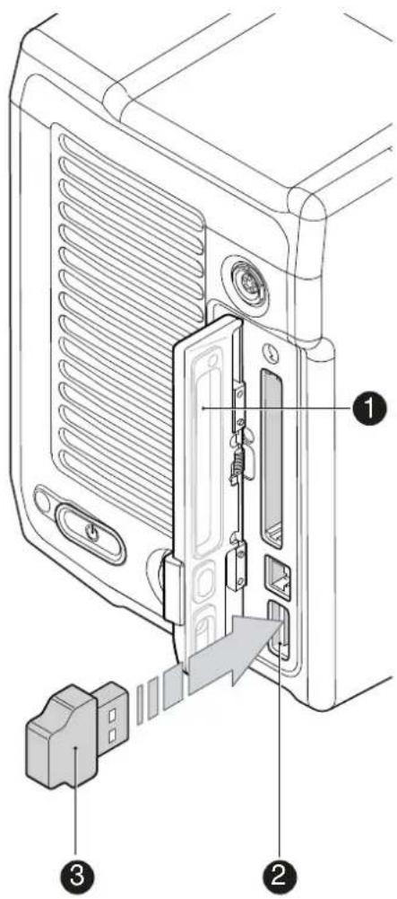
- For external frame files: Store the required file(s) into ARRI/A-MINI/FRAMELINES on a properly prepared USB memory stick. See page 111.
- Open the media lid (1).
- Connect the memory stick (3) to the camera (2).
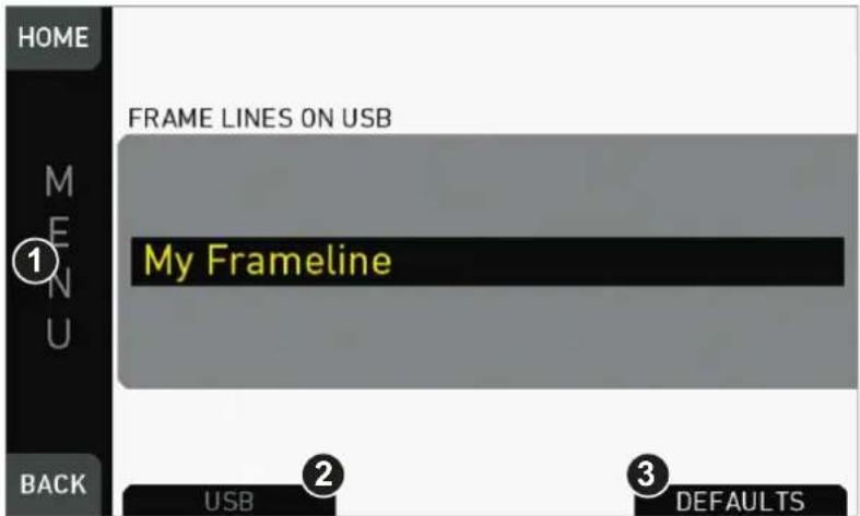
- Only then, press USB (2).
- Via jogwheel (1), select and install all required frame lines.
17.3.2 Deleting a frame line
MENU > Monitoring > Frame lines > Frame line
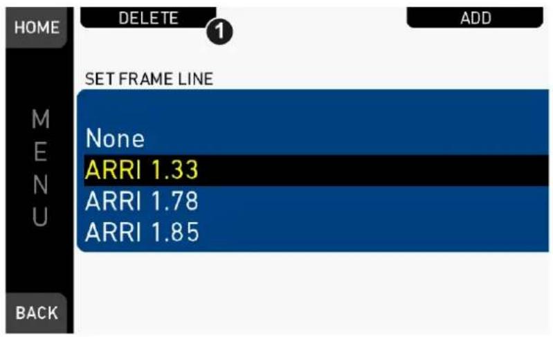
- Via jogwheel, open MENU > Monitoring > Frame lines > Frame line.
- Press DELETE (1).
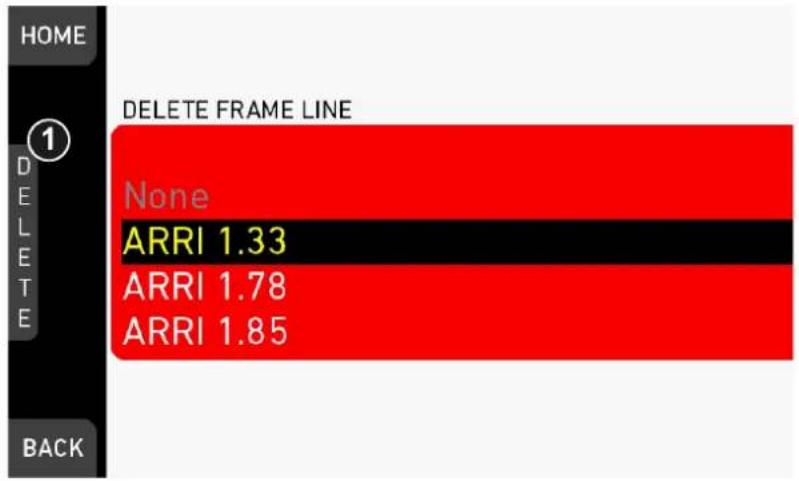
- The list turns red.
- Via jogwheel (1), select the obsolete entry.
- Press the wheel (1).
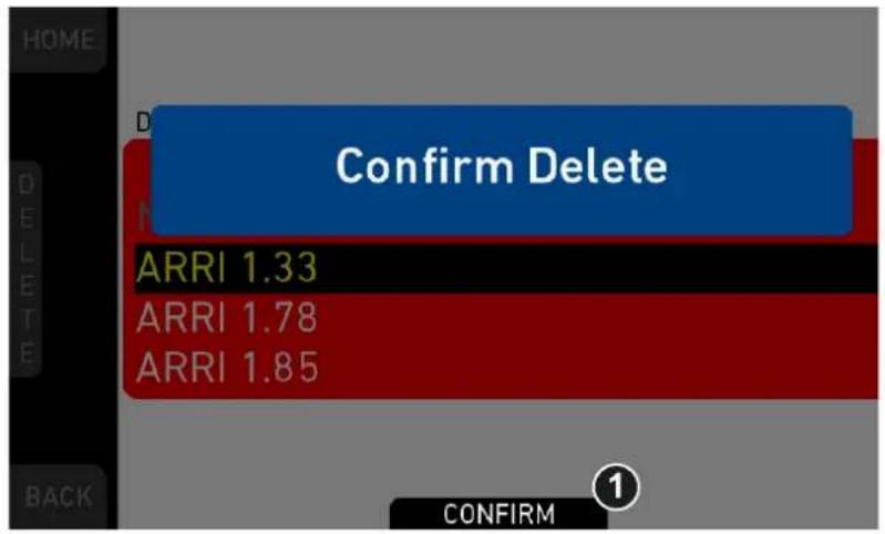
-
Press CONFIRM (1). Cancel with BACK.
-
The entry is deleted.
17.3.3 User rectangle 1 & 2
MENU > Monitoring > Frame lines > User Rectangle 1 & 2
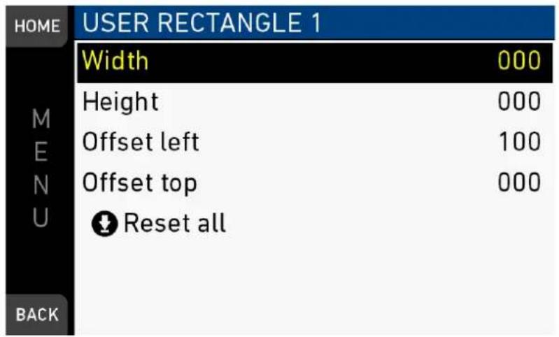
Configures Width, Height and Offset (= position from left/right screen edge) in per mille.
Reset all: Resets the configuration.
17.4 Color bars
Activates a SMPTE color bar on SDI outs.
Note: Recording deactivates the color bar.
18 MENU > System
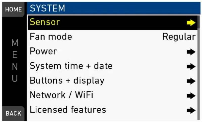
The system menu organizes the general camera setup.
Sensor: Sets sensor related parameters.
Fan mode: Adapts the camera cooling to several shooting situations.
Power: Edits the thresholds for critical voltage levels and other warnings.
System time + date: For synchronizing the system to timezones etc.
Buttons + display: Modifies the button/display illumination and style.
Network / WiFi: Sets up the camera's WiFi module.
Licensed features: Manages the camera licensing.
18.1 Sensor
MENU > System > Sensor
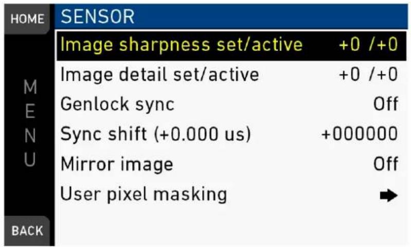
Image sharpness set/active: Adjusts the image sharpness between -5 and +5 (default = 0).
Image detail set/active: Adjusts the maximum detail frequency influenced by the sharpness setting in a range between -5 and +5 (default = 0).
Genlock sync: Sets external sync to Off, RET/SYNC IN or TC IN:
- When set to RET/SYNC IN, the camera requires a Black Burst or Tri-Level sync signal with sensor fps for the SYNC IN BNC connector.
- When set to TC IN, the camera requires a Timecode sync signal with sensor fps for the TC connector.
- Note: Genlock sync via RET/SYNC IN requires hardware modification of the camera to function. Contact ARRI service for more information.
Sync shift (+ 0.000 s): Offset applied to the genlock signal at the input. Minimum stepsize is 52 ns, maximum possible correction is +/- 20 ms (= 384000 steps).
Mirror image: Mirrors the sensor image on all image paths vertically (V), horizontally (H), or both (V+H).
User pixel masking: Opens a sub-screen, where the user can upload a user pixel mask from the USB. The user pixel mask allows to correct user selected defect sensor pixels.
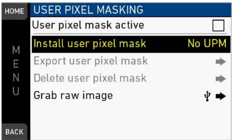
NOTICE
User pixel masks can be created with the ARRIRAW Converter for Mac and Windows, available for download from the ARRI website. Please refer to the ARRI website and the ARRIRAW Converter documentation for additional information.
18.2 Fan mode
MENU > System > Fan mode
Optimizes the camera cooling for different shooting situations.
Regular: Creates a balance between fan noise and camera temperature.
Rec low: Increases fan speed during standby to pre-cool the camera. Minimizes fan speed/noise during recording.
Note: Ideal in an environment warmer than 25 °C (77 °F).
Low Noise: Minimizes fan noise during both standby and recording.
Note: With data rates above 100 MB/s (due to fps/codec setting), the fan speed automatically increases to prevent CFast 2.0 cards from overheating.
18.3 Power
MENU > System > Power
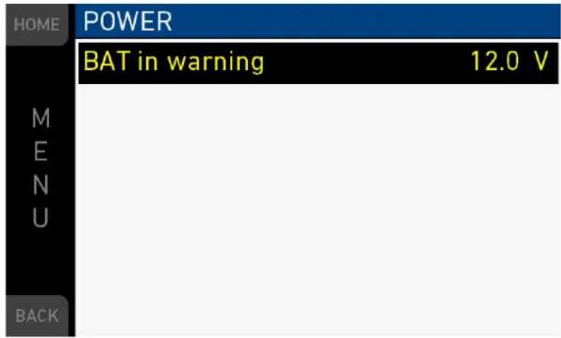
BAT in warning: Sets the voltage level that triggers a power warning for external batteries on the BAT connector.
18.4 System time + date
MENU > System > System time + date
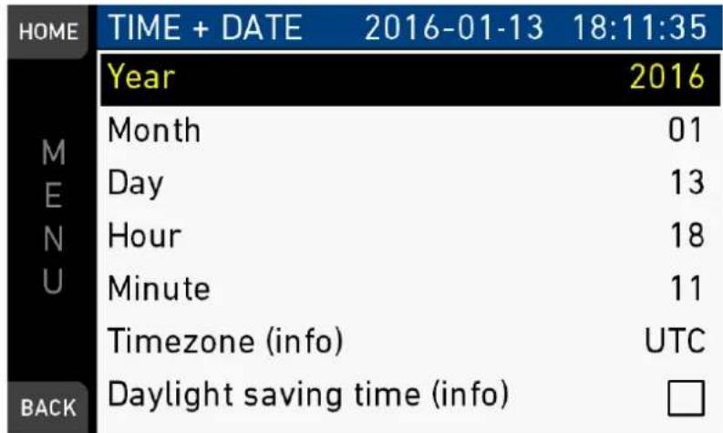
Note: Timezone and Daylight savings time do not change time and date settings. They are only stored as metadata in the recorded clips.
18.5 Buttons + display
MENU > System > Buttons + display
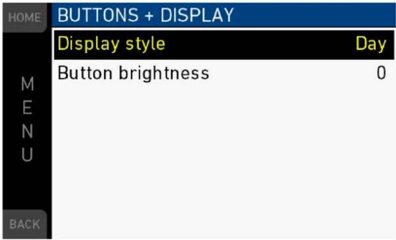
Display style: Changes the display style between Day and Night mode.
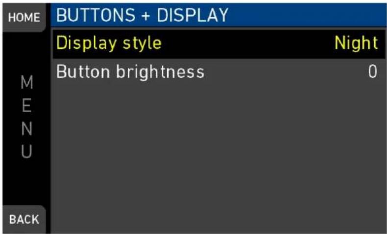
Button brightness: Sets the brightness of the button illumination in a range of 0 to 3.
18.6 Network / WiFi
MENU > System > Network / WiFi
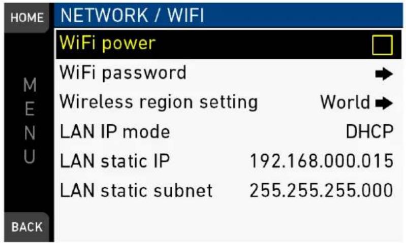
WiFi Power: Sets power of camera WiFi on or off.
WiFi password: Sets the WiFi password. The default WiFi password is arriarri. Note: WiFi passwords must be 8-32 characters long.
Wireless region setting: Navigates to a sub-screen, where the wireless region setting can be set.
LAN IP mode: IP configuration can be changed between manual and DHCP. Note: For manual mode the values can be set.
LAN static IP: Shows the static IP address.
LAN static subnet: Shows the static subnet address.
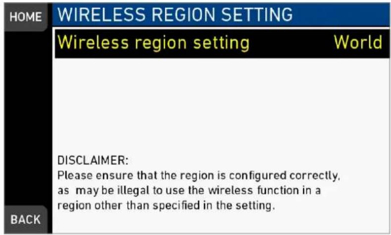
CAUTION!
Wireless region settings specify where the wireless function can be used in compliance with local regulations. It may be illegal to use the wireless function in a region other than specified in the setting. Please ensure that the region is configured correctly (e.g. when traveling).
18.7 Camera update
While the camera is updating, the information is shown.
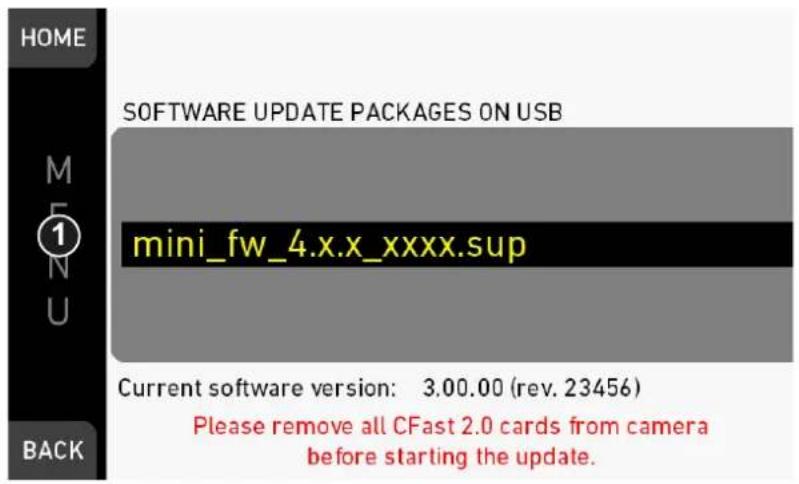
Allows the installation of SUP software update packages.
Note: For update instructions, see page 162.
19 MENU > Setup
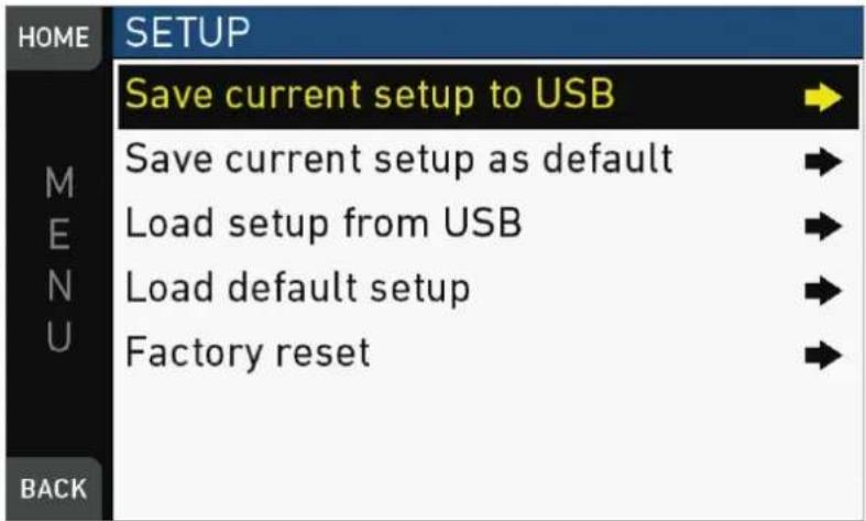
Setups allow you to store/load full camera configurations.
Save current setup to USB: Stores the configuration on the USB stick (ARRI/A-MINI/SETUPS). You can rename this user setup file beforehand.
Save current setup as default: Stores the current configuration on the camera.
Survives a factory reset. Serves as an alternative to a factory reset if other settings are required as default.
Load setup from USB: Loads a setup from the USB stick.
Load default setup: Loads the default setup from the camera.
Factory reset: Sets the camera to ARRI factory default values.
MENU > Setup > Save current setup to USB
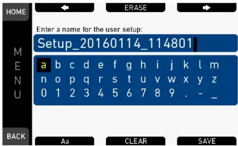
▶ Type the user setup name.
MENU > Setup > Load setup from USB
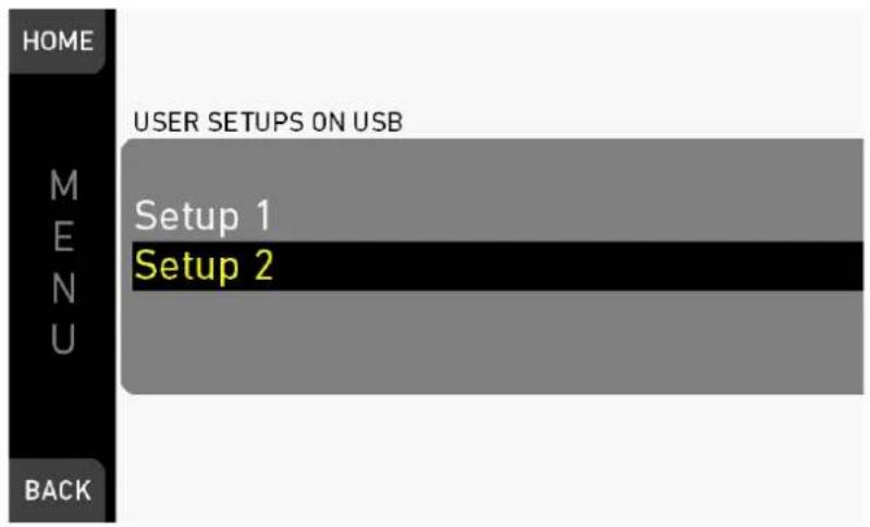
▶ Load the user setup from USB.
MENU > Setup > Save current setup as default
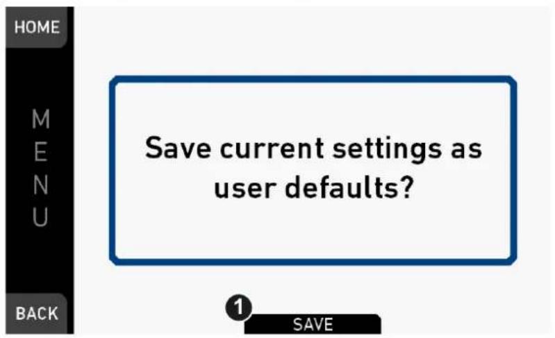
▶ Press SAVE to save the settings as user defaults.
MENU > Setup > Factory reset
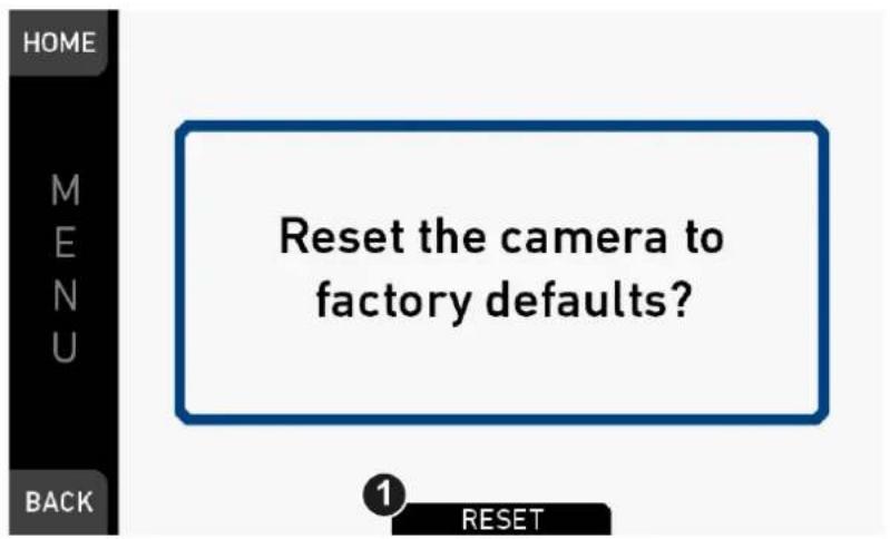
▶ Press RESET to reset the camera to factory defaults.
20 MENU > User buttons
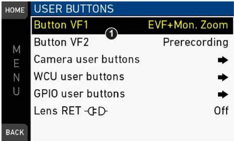
Button VF1 / VF2: Set the function of the VF1 and VF2 button on the viewfinder (1).
Camera user buttons: Submenu with camera user buttons 1-8.
WCU user buttons: Submenu with user buttons of WCU-4*.
GPIO user buttons: Submenu with user buttons connected via a GPIO box.
Lens RET: RET button of ENG lens. Requires special lens. If not supported by lens, a disconnected plug in is shown behind menu entry.
* Configuration valid for WCU-4 connected to ALEXA Mini. WCU-4 requires software version 2.1 or later to support smart behavior of buttons.
MENU > User buttons > Camera user buttons
| HOME | CAMERA USER BUTTONS | |
| Button 1 | EVF+Mon. Zoom pos. | |
| M E N U | Button 2 | Off |
| Button 3 | Off | |
| Button 4 (web) | Off | |
| Button 5 (web) | Off | |
| Button 6 (web) | Off | |
| BACK | Button 7 (web) | Off |
Button 1-3: Set the functions of user buttons 1-8 on the left camera side, plus buttons 5-8, available via web remote.
MENU > User buttons > WCU user buttons
| HOME | WCU USER BUTTONS | |
| Button 1 | Off | |
| M | Button 2 | Off |
| E | Button 3 | Off |
| N | Button 4 | Off |
| U | ||
| BACK | ||
User/VF button functions
The following user and VF button functions are available:
• Off: Disables the user button
- EVF+Mon. Desqueeze: Toggles anamorphic desqueeze on EVF and monitor (not active in 16:9 modes).
- EVF+Mon. Zoom: Switches the viewfinder zoom function on or off*. Supports smart behavior.
Note: Zoom image is monochrome.
- EVF+Mon. Zoom pos.: Selects the next zoom area position.
- EVF+Mon. Frame Lines: Switches viewfinder frame lines on or off*. Supports smart behavior.
- EVF+Mon. Zebra/FC: Toggles the exposure tool between Zebra and False Color*.
- EVF+Mon. Gamma: Toggles the viewfinder gamma between Look and Log C*. Supports smart behavior.
- EVF+Mon. Surround: Switches the surround view on or off*. Supports smart behavior.
- EVF+Mon. Peaking: Switches peaking on or off*. Supports smart behavior.
- EVF+Mon. Exp. Tool: Switches the exposure tool on or off*. Supports smart behavior.
• EVF Status Info: Switches the status info on or off.
- EVF Waveform: Switches the EVF waveform overlay on or off. Supports smart behavior.
- Monitor Waveform: Switches the Monitor waveform overlay on or off. Supports smart behavior.
- Flip Monitor: Switches the monitor flip function on or off.
- SDI Desqueeze: Toggles anamorphic desqueeze on SDI (not active in 16:9 modes).
- SDI Frame Lines: Switches viewfinder frame lines on or off*. Supports smart behavior.
- SDI Zebra/FC: Toggles the exposure tool between Zebra and False Color*.
- SDI Gamma: Toggles the SDI gamma between Look and Log C*. Supports smart behavior.
- SDI Surround: Switches the surround view on or off*. Supports smart behavior.
- SDI Peaking: Switches peaking on or off*. Supports smart behavior.
- SDI Exp. Tool: Switches the exposure tool on or off*. Supports smart behavior.
- SDI Status info: Switches the status info on or off.
- Auto WB: First press arms auto white balance for one second, second press within one second triggers AWB.
- Button 'FN': Behaves identically to FN button on camera body. Note: Only available for GPIO box user buttons.
- Button '1': Behaves identically to button 1 on camera body. Note: Only available for GPIO box user buttons.
- Button '2': Behaves identically to button 2 on camera body. Note: Only available for GPIO box user buttons.
- Button '3': Behaves identically to button 3 on camera body. Note: Only available for GPIO box user buttons.
- Check Last Clip: Plays the last five seconds of the last recorded clip.
- Color Bar: Turns color bar on or off. Activation works only during Stby.
- EF Auto Iris: Triggers automatic iris compensation***.
- EF Open Iris: Opens the iris of a lens. Short press opens by 1/x stop (step size depending on lens), long press opens by 1 stop per 0.5 seconds***.
- EF Close Iris: Closes the iris of a lens. Short press closes by 1/x stop (step size depending on lens), long press closes by 1 stop per 0.5 seconds***.
- El Decrease: Decreases camera Exposure Index by 1 value.
- El Increase: Increases camera Exposure Index by 1 value.
- Framegrab: Grabs a still frame in .JPG and .DPX format and saves it to the USB stick in the GRABS directory (during Standby only).
Note: Framegrabs are taken from the clean SDI image path and cropped to the active image area (without black borders). - Frame Line Color: Changes the frame line color.
- ND Decrease: Decreases the active ND filter by 1 step.
- ND Increase: Increases the active ND filter by 1 step.
- Overlay Menu: Activates or deactivates the overlay menu on MVF-1 EVF, monitor and SDI (when SDI processing is activated).
- Playback: Behaves identically to PLAY button on MVF-1.
- Prerecording: Switches pre-recording on or off.
- Record Start/Stop: Behaves identical to record button.
- Stop Motion Trigger: Triggers the capture of a single frame during recording in recording mode Stop Motion.
- WiFi Power: Toggles WiFi power On and Off.
* Affects both viewfinder and monitor settings.
*** Requires EF lens mount and a suitable EF lens.
User button smart behavior: For these user button functions, a short press toggles the function, while a longpress activates the function only temporarily.
Example: Press EVF zoom long > EVF zoom function is activated, release of button deactivates zoom. Press EVF zoom short > EVF zoom is activated. Press again to deactivate.
MENU > User buttons > GPIO user buttons
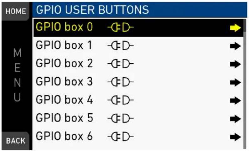
The ARRI GPIO box (GPB-1, K.2.0007642) can be used as an interface to the camera for external user buttons. It connects to the camera via the EXT connector and has a 37-pin D-Sub connector carrying 14 GPI (General purpose input) connections plus 2 outputs (camera power status and camera recording status). Currently, the GPIO box is hard-mapped to channel 0. For additional information, please refer to the user manual of the GPB-1.
MENU > User buttons > GPIO user buttons > GPIO box
| HOME | GPIO BOX 0 | |
| Button 1 | Off | |
| M | Button 2 | Off |
| E | Button 3 | Off |
| N | Button 4 | Off |
| U | Button 5 | Off |
| Button 6 | Off | |
| Button 7 | Off | |
| BACK | ||
21 MENU > Metadata
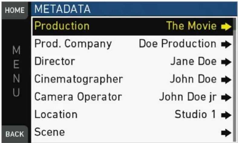
Allows you to enter static production metadata to the recorded Quicktime files.
● Production: Field for the name of the production
• Prod. Company: Field for the name of the production company
- Director: Field for the director's name
- Cinematographer: Field for the cinematographer's name
- Camera operator: Field for the camera operator's name
- Location: Field for the location name
- Scene: Field for the scene number
• Take: Field for the take number
- User info 1 & 2: Fields for additional info.
![HOME Set Cinematographer John Doe a b c d e f g h i j k l m n o p q r s t u v w x y z 0 1 2 3 4 5 6 7 8 9 . - _ [ ] BACK Aa CLEAR DONE](/content/2026/05/813522/images/b8a81c7f98f8b03c14dbc6d1bab99fa92dd96c8b29a33ddd6d6539ca5678b0cf.jpg)
For editing, see page 89.
22 MENU > Electronic Control System (ECS)
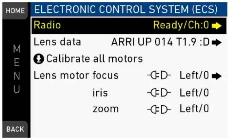
Radio: Sets the functions of the white radio power module.
Lens data: Provides information about LDS lenses or passive lenses using lens data tables.
Calibrate all motors: Starts the calibration of the motors.
Lens motor focus/iris/zoom: Sets the torque and motor direction for the focus, iris, and zoom.
22.1 Radio
MENU > Electronic Control System (ECS) > Radio
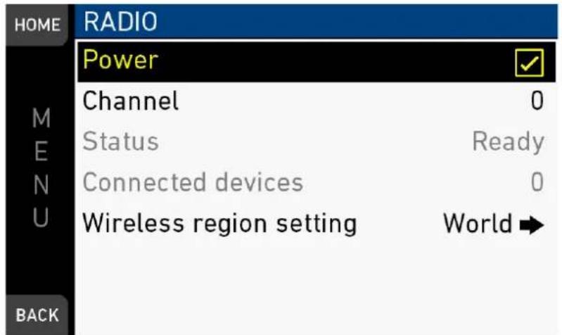
Power: Switches white radio module power on or off.
Channel: Sets the channel of the ECS module.
Status: Shows the status of the ECS module.
Connected devices: Shows the number of ECS devices connected to the camera.
Wireless region setting: Configures the region where the wireless function is used.
The wireless remote system (WRS) menu screen controls the ECS white radio settings. The WRS system connects the camera to electronic accessories like the WCU-4 for wireless camera and lens remote control.
CAUTION!
Wireless region settings specify where the wireless function can be used in compliance with local regulations. It may be illegal to use the wireless function in a region other than specified in the setting. Please ensure that the region is configured correctly (e.g. when traveling).
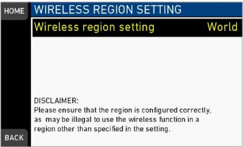
22.2 Lens data
MENU > Electronic Control System (ECS) > Lens data
Lens data can be provided by two different ways, depending on the type of lens:
LDS lenses: These lenses contain an integrated electronic interface that communicates information about focus, iris and zoom directly to the camera.
Non-LDS lenses: These lenses do not have a LDS interface, hence information about focus, iris and zoom need to be gathered from lens motors and translated into sensible values by the help of lens tables. These lens tables are stored in the Lens Data Archive (LDA).
Example: LDS lens
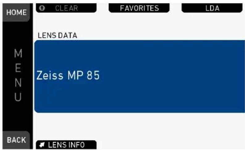
Example: Non-LDS lens
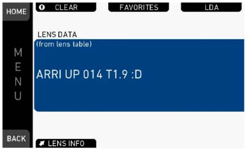
The lens data archive (LDA) contains lens tables, which offer lens data functionality with non-LDS lenses in conjunction with lens motors. It is possible to add or delete lens tables from the lens data archive. From the default tables and the USB tables, a selection of lens tables can be imported into the camera.
To add lens tables from a USB stick to the camera, place them in the folder /ARRI/A-MINI/LDA/ to be detected by the camera.
Note: It is possible to load a lens table even when a LDS lens is attached. The LDA values calculated from motor positions and lens tables take precedence over the values communicated by the lens itself. This can be necessary if the lens data from the lens is imprecise.
- Open lens data archive by pressing LDA (1).
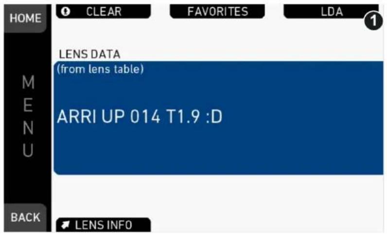
- Add a lens table by pressing ADD.
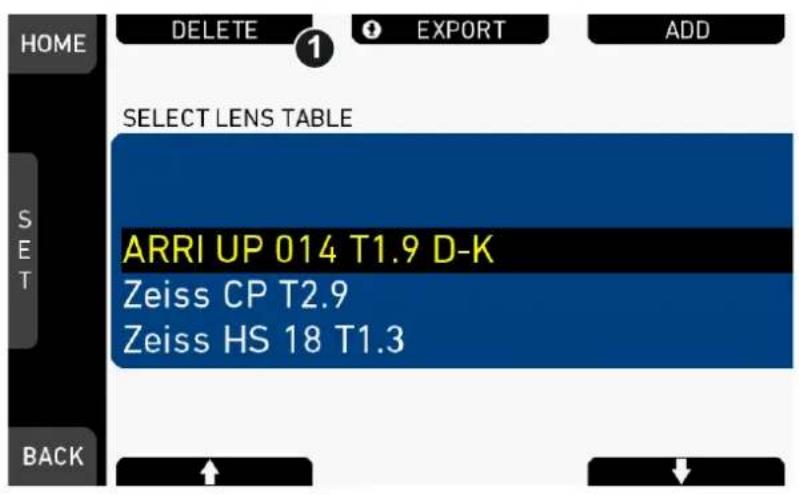
- Select a lens table by pressing USB or DEFAULTS to select from included lens tables.
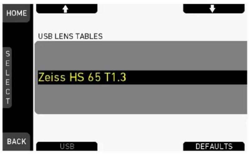
Some lens tables contain different scale classes for the same model. The scale class of an individual lens is engraved on the housing.
- If required: Select a scale class by pressing the jogwheel.
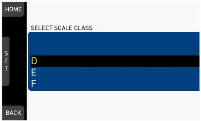
▶ Add the selected lens table to favorites without activating the lens table by pressing ADD TO FAV.
▶ Add the selected lens table to favorites and activate it by pressing FAV.+USE.
▶ Activate the selected lens table without adding it to favorites by pressing USE.
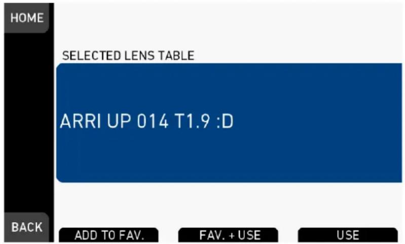
Favorites list
The favorites list shows all lenses that have been added explicitly before, including the selected scale class.
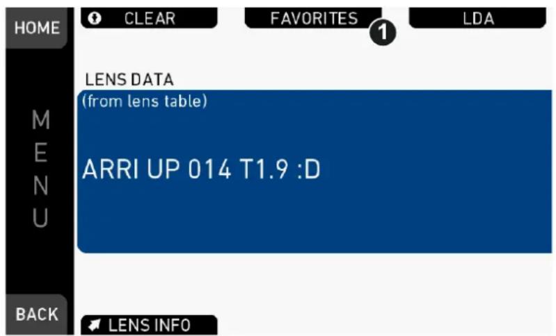
- Open the favorites list by pressing FAVORITES (1).
- Select a lens to choose or delete from the favorites list.
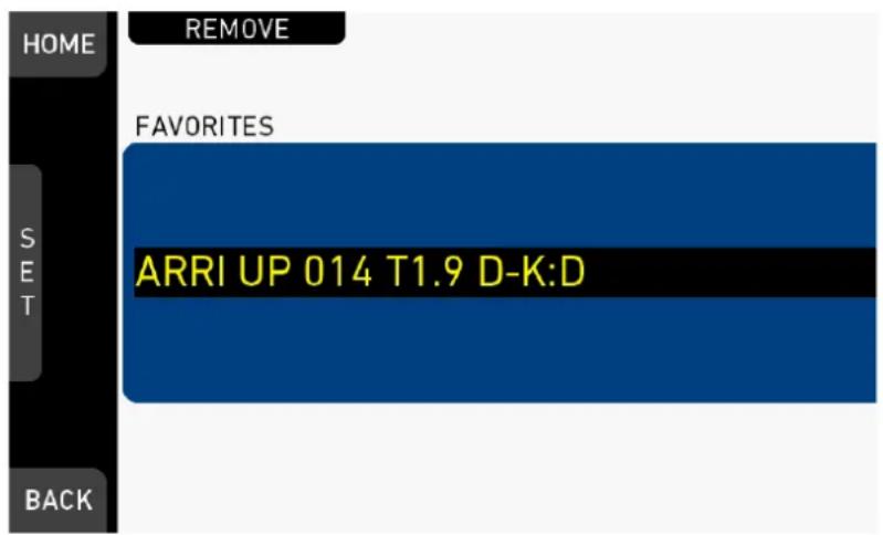
Add or delete a lens table
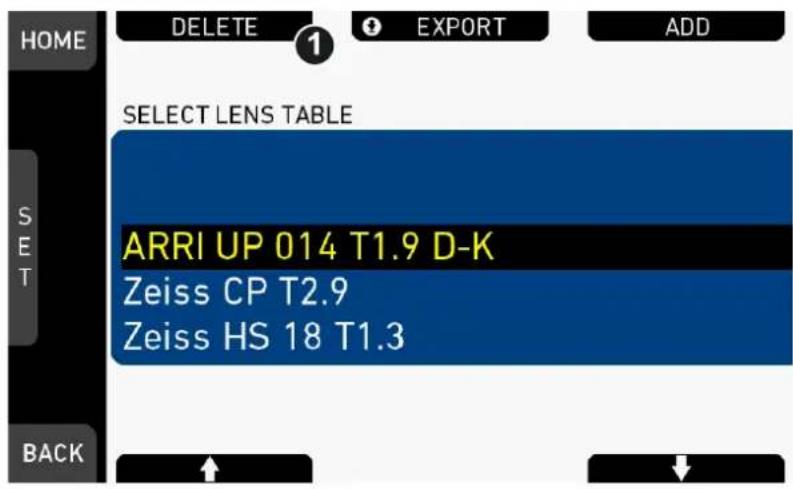
- Select a lens table to add or to delete (here: delete).
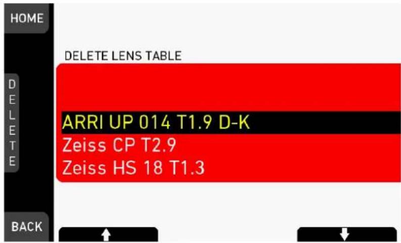
The list turns red.
- Press DELETE.
- A message asks for confirmation.
- Press CONFIRM. Cancel with BACK.
The entry is deleted.
LDA and WCU-4
LDA tables created with WCU-4 need to be manually copied from WCU-4 SD Card folder /ARRI/ALEXA/LDA/ to Alexa MINI USB folder /ARRI/A-MINI/LDA/ in order to import the tables into ALEXA Mini. Note that only lens tables created with WCU-4 software version 2.22.22 or later are supported.
Please see "Prepare USB medium" for creating the required folder structure on your USB stick.
22.3 Calibrate all motors
MENU > Electronic Control System (ECS) > Calibrate all motors
Triggers a calibration of all connected lens motors.
NOTICE
Do not trigger a calibration unless all connected motors are attached to the lens.
22.4 Lens motor focus
MENU > Electronic Control System (ECS) > Lens motor focus
| HOME | LENS MOTORS | |
| Focus motor torque | 0 | |
| M | Focus motor direction | Left |
| E | Iris motor torque | 0 |
| N | Iris motor direction | Left |
| U | Zoom motor torque | 0 |
| Zoom motor direction | Left | |
| BACK | ||
Focus/Iris/Zoom motor torque: Sets the torque strength of the focus/iris/zoom axis motor.
Focus/Iris/Zoom motor direction: Sets the motor direction of the focus/iris/zoom axis motor. The direction may have to be changed depending on the mounting position of the motor (left/right side or top/bottom).
23 Camera preparation
23.1 Adjusting the MVF-1
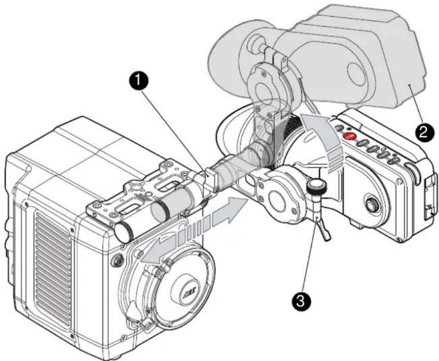
- Place the camera bottom-down.
- Slightly loosen the clamp (1) to move the MVF-1 (2) left/right and up/down.
- Unclamp the hinge (3) to swivel the MVF-1 horizontally.
- Close all clamps (1, 3) when the MVF-1 is in the desired position (2).
23.2 Mounting to a bridge plate
To mount the camera to a bridge plate, you need the following accessories and tools:
| Step Accessory Mount to Tool | |||
| 1 MAP-2 | camera (bottom) 3.0 mm | Allen key | |
| 2 BAP-4 | MAP-2 | Flat screwdriver (no coin!) | |
| 3 BP-8 | BAP-4 | ||
Step 1: Mounting the MAP-2 to the camera
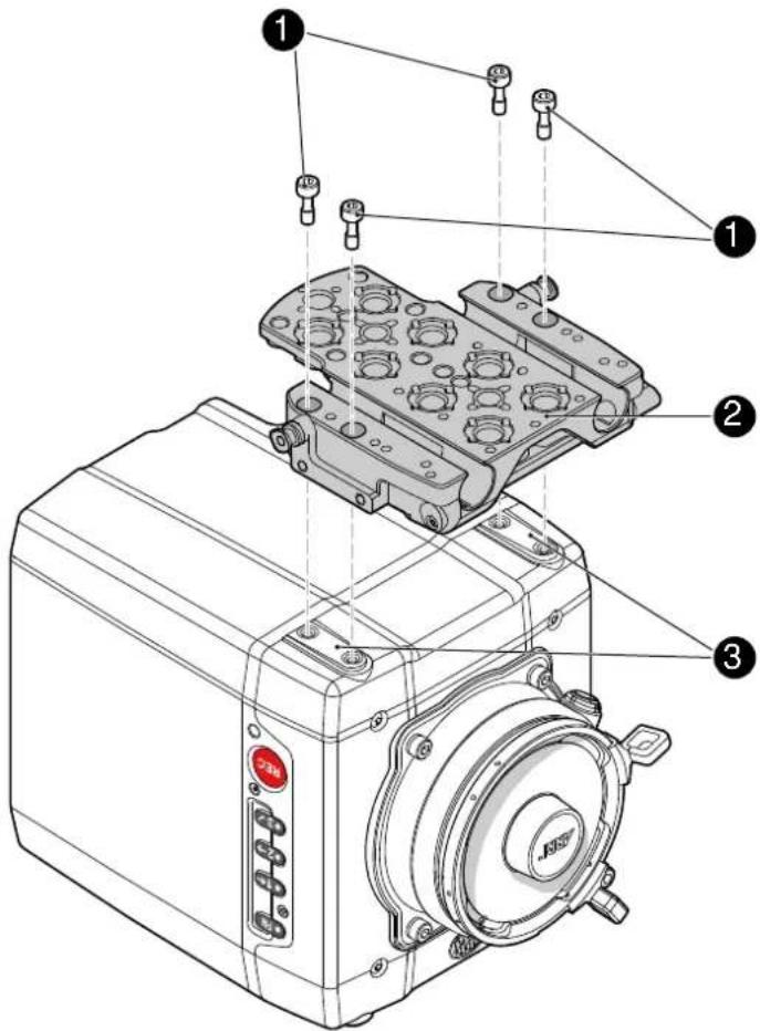
- Place the camera bottom-up.
- Place the MAP-2 (2) exactly above the mounting points (3) of the camera.
- With the Allen key, attach the screws (1) to the camera and tighten.
| NOTICE |
| Always ensure a proper lock. |
Step 2: Mounting the BAP-4 to the MAP-2
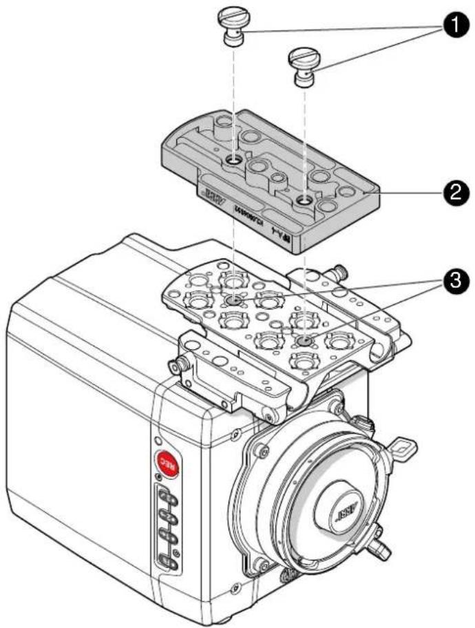
- Place the BAP-4 (2) exactly above the mounting points (3) of the MAP-2 (2).
- With a flat screwdriver, attach the screws (1) to the MAP-2 and tighten.
NOTICE
Always use a flat screwdriver to connect the BAP-4 to the MAP-2. Never use a coin. A coin does not deliver enough force to ensure a proper lock.
Step 3: Mounting the BP-8 to the BAP-4
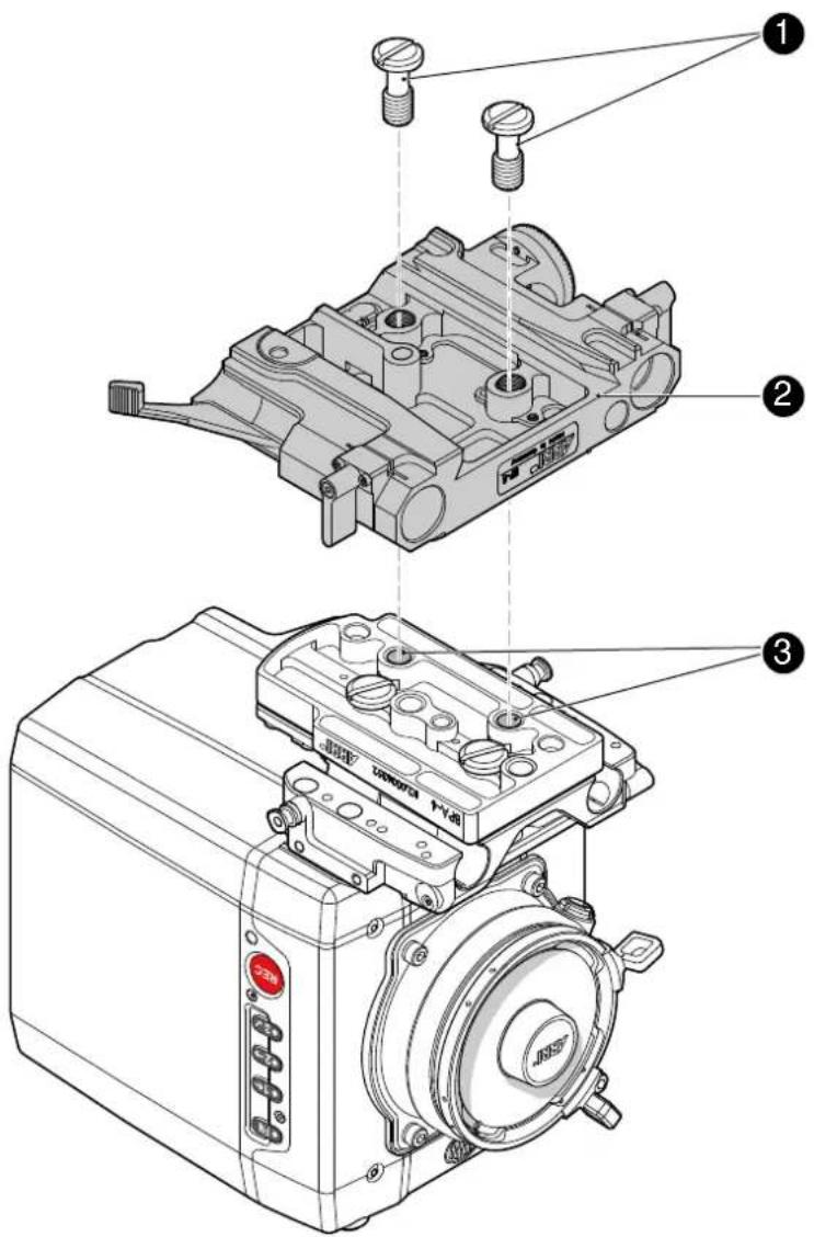
- Place the BP-8 (2) exactly above the mounting points (3) of the BAP-4 (2).
- With a flat screwdriver, attach the screws (1) to the BAP-4 and tighten.
NOTICE
Always use a flat screwdriver to connect the BP-8 to the BAP-4. Never use a coin. A coin does not deliver enough force to ensure a proper lock.
24 Assembly and retrofits
NOTICE
To avoid damage while assembling and retrofitting, always place the camera on a padded, firm, flat and level surface.
Work on an unpowered camera only.
24.1 MVF-1 and EVF cable
Connecting the EVF cable to the camera
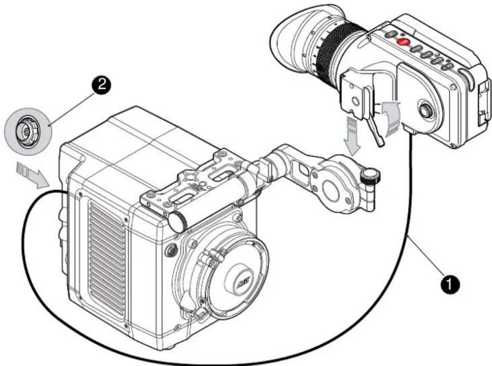
Note: Use original ALEXA Mini-EVF cables only.
▶ Connect the EVF cable (1) to the camera (16-pin ODU connector (2) on the I/O panel).
CAUTION!
Never try to connect the cable to any other connector on the camera than the EVF connector. This may cause permanent damage to both cable and camera connectors.
Connecting the EVF cable to the MVF-1
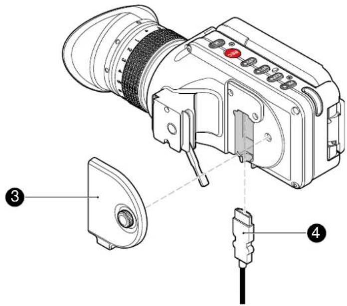
- Switch off; interrupt the power supply.
Note: Use original ALEXA Mini-EVF cables only.
- With your fingers, unscrew and remove the MVF-1's lid (1).
- Connect the cable (2) to the EVF port.
- Reattach the lid (1).
24.2 Camera handle
Tool needed
• 3.0 mm Allen key
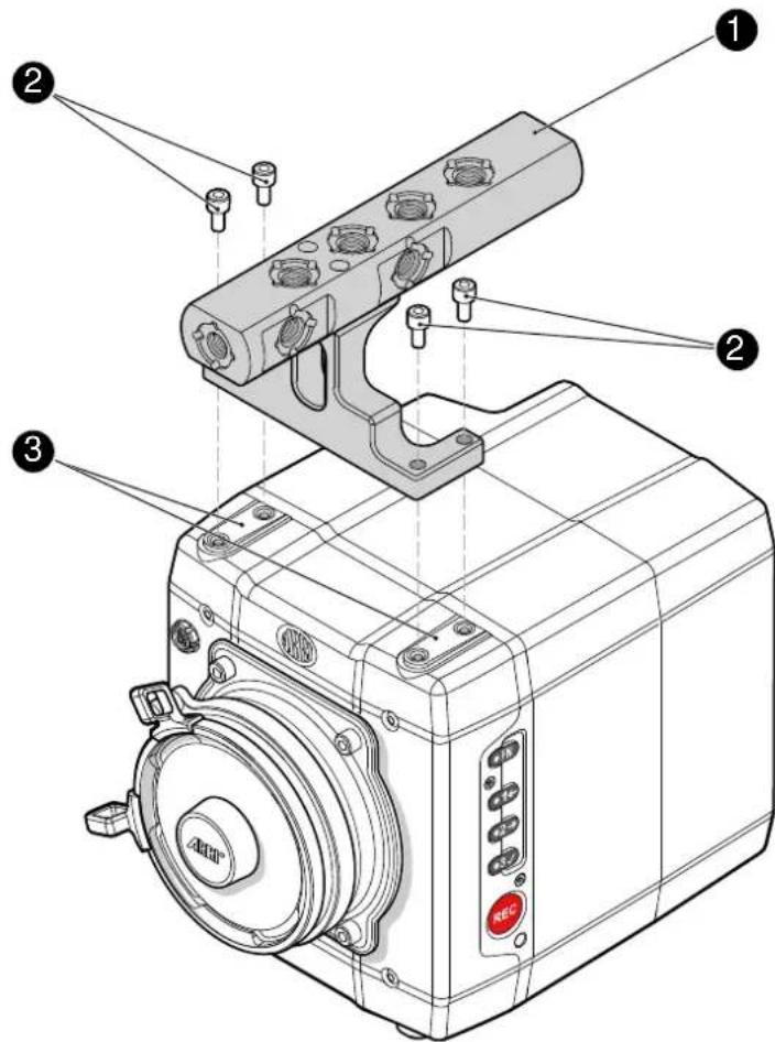
- Place the camera handle (1) exactly above the mounting points (3) of the camera.
- With the Allen key, attach the screws (2) to the camera and tighten.
NOTICE
Always ensure a proper lock.
24.3 Antenna
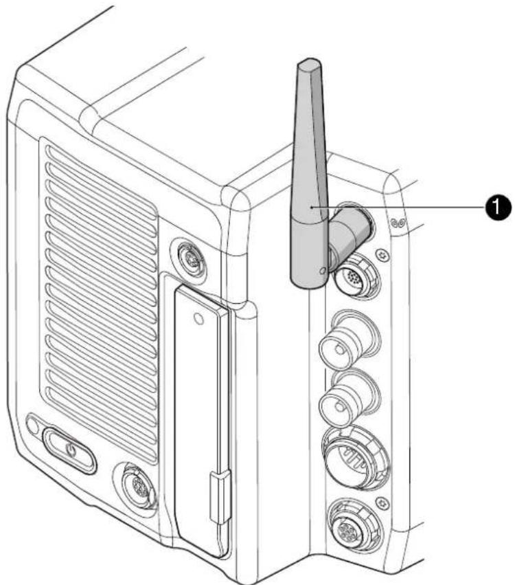
natural_image
Technical line drawing of a device rear panel with labeled ports and components (no text or symbols)- With your fingers, thread the antenna for white radio (1) onto the camera.
- To unmount: Unthread the antenna (1) with your fingers.
24.4 Changing a lens mount
WARNING!
High voltage! Risk of electric shock and fire!
Short circuits may entail lethal injury and damage!
Use original ALEXA-Mini or AMIRA lens mounts only.
Before each lens mount change, always switch the camera off and disconnect all power sources.
Changing the lens mount while the camera is powered may permanently damage the camera and lens mount.
Protect sensor and electrical system: Always store the camera with a lens mount properly installed and capped.
Immediately replace each lens mount after removal.
Change lens mounts in dust-free environment only.
NOTICE
After each lens mount change, always check the back focus of the camera.
Have the back focus always corrected by properly skilled personnel.
Back focus correction requires special tools and training that meet ARRI guidelines.
For all back focus issues, contact a qualified ARRI Service Center.
Tools and provisions needed
- 3 mm Allen key
- Switch the camera off
- Disconnect all power sources
• Properly cap, disconnect, and store the lens
Deinstallation (here: a PL mount)
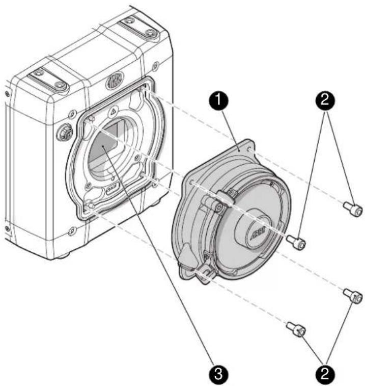
- Perform task with care to protect optical surfaces.
- Crosswise, loosen all four screws (2) with an Allen key.
- Carefully remove the mount (1).
- Store the mount in a case for dust protection.
Note: To protect the sensor (3), immediately install another original ALEXA lens mount.
Installation (here: a PL mount)

WARNING!
Condensation! Risk of electric shock and damage!
Humidity may ingress due to misinstalled lens mounts!
When installing a lens mount, always align and attach properly; never apply force.
Hand-tighten all screws crosswise before final tightening.
Always tighten crosswise with the prescribed tool.
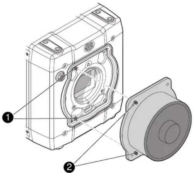
- Properly align the two guiding pins (1) for correct lens mount fit (2).
Note: Never apply force, align the guiding pins instead.
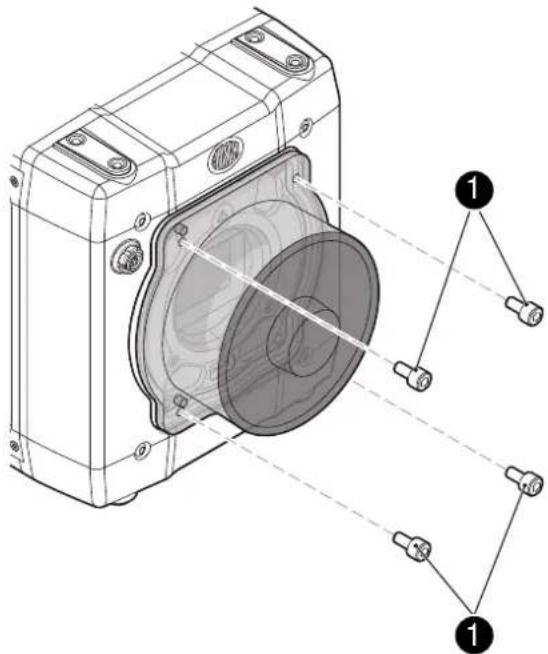
-
Crosswise, hand-tighten all four screws (1).
-
Only then, tighten all screws crosswise with the Allen key.
Note: Always store the camera with a lens mount properly installed and capped.
24.5 CCP-1
The Camera Control Panel-1 (CCP-1) is a standalone control panel, containing the display and a subset of buttons of the MVF-1. It shows the same images, and the buttons mimic the behavior of the equivalent buttons of the MVF-1. It can be used as the only control panel or with a MVF-1 daisy-chained to it.
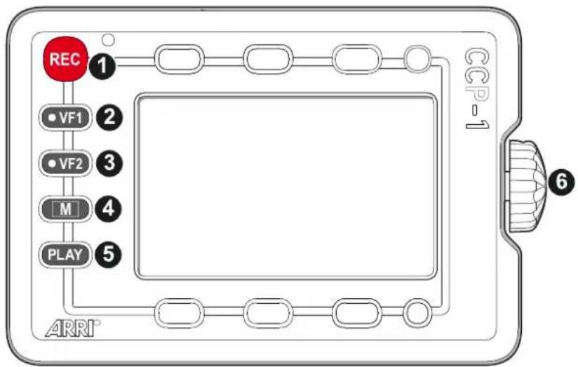
flowchart
graph TD
    REC["REC"] --> 1["1"]
    1 --> 2["2"]
    2 --> 3["3"]
    3 --> 4["4"]
    4 --> 5["5"]
    5 --> 6["6"]
    6 --> ARRI["ARRI"]
1 Recording button 4 Monitor button
2 VF-1 user button 5 Play button
3 VF-2 user button 6 Jogwheel
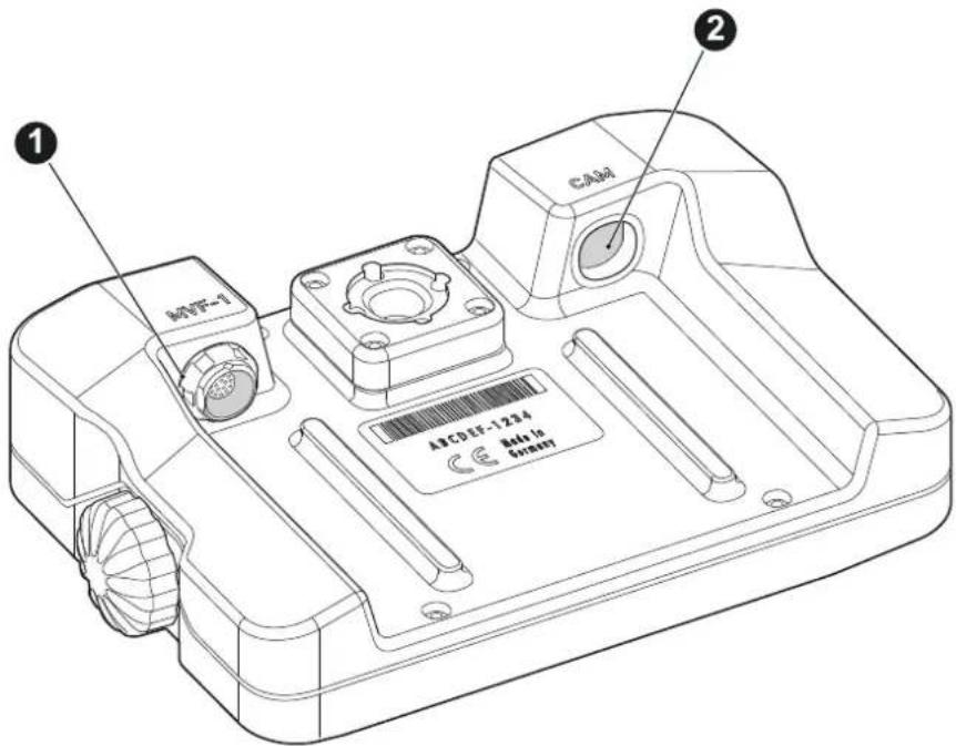
1 MVF-1 connector
2 CAM connector
Connect CCP-1 to the EVF out port of the camera.
When it is used alone with the camera, it always shows an image.
When a MVF-1 is chained to the CCP-1, the MVF-1 will show an image in the EVF, but only one of the two monitors, either of the MVF-1 or the CCP-1 is active.
- If the monitor of the MVF-1 is closed, the CCP-1 is activated.
- If the monitor of the MVF-1 is opened, the monitor will be activated.
▶ Activate the MVF-1 by pressing a screen button on the MVF-1.
▶ Activate the CCP-1 by pressing any button except "REC" button on the CCP-1.
24.6 Transvideo StarliteHD5-ARRI Monitor
The Transvideo Starlite HD5-ARRI monitor (K2.0006960) is a 5" 3G-SDI Oled monitor with an integrated H.264 recorder, a touchscreen and a special ARRI bus interface to communicate with the camera. It allows basic operation of an ALEXA Mini camera.
All overlays that are required for touch operation are generated by the camera and transferred to the Starlite monitor via HD-SDI. For this reason, monitors daisy-chained to the Starlite will show the overlays as well.
- Connect the monitor to an SDI out of the camera. Make sure the SDI processing of the output is activated.
- Connect the bus interface cable to the EXT port of the camera.
- Activate the overlay menu by pressing the "ARRI" touch icon on the monitor.
- Select a parameter with arrow icons of the monitor.
- Start editing the parameter by pressing checkmark icon.
- Select the new parameter value with the arrow icons.
- Confirm the new value by pressing the checkmark icon.
- If required, repeat steps 4-7 for other parameters.
- Exit the overlay menu by pressing the exit icon.
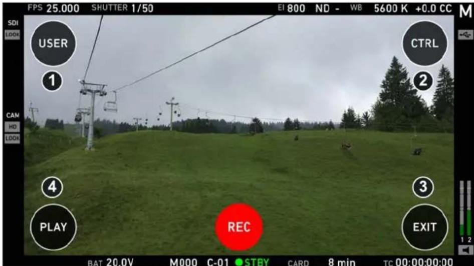
▶ Activate the ARRI menu by pressing the blue "A" touch icon on the monitor.
The main screen is opening up and you can access the user menu (1), the control menu (2), and the playback menu (4).
▶ Start and stop recording by pressing the red "REC" touch icon on the monitor.
▶ Exit the ARRI menu by pressing the "EXIT" (3) touch icon on the monitor.
All overlays disappear after some seconds of inactivity.
Note: In the ARRI menu, standard Starlite functionality are not available.
User menu
In the user menu, the same functions are available as with the camera user buttons (1) to (3).
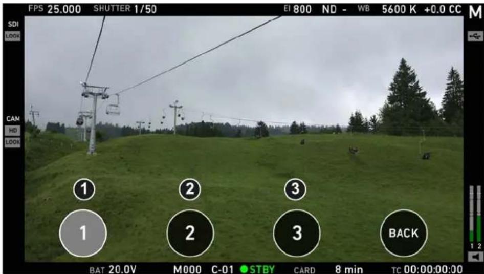
▶ The grey button indicates an active user function (e.g. (1)).
▶ Exit the user menu by pressing the "BACK" touch icon on the monitor.
Control menu
In the control menu, camera parameters can be edit similar to the overlay menu. page 50
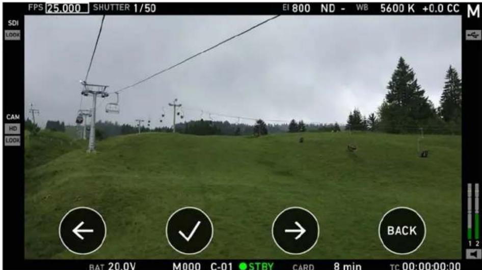
▶ Choose a parameter by pressing the touch icon (1) or (3) on the monitor.
▶ Select the parameter by pressing the touch icon (2) on the monitor.
The parameter can be edited.
▶ Exit the control menu by pressing the "BACK" (4) touch icon on the monitor.
Note: The control menu is not available during playback.
Playback menu
In the playback menu, recorded clips can be played or paused (2) and skipped to previous (1) or next (3) clip.
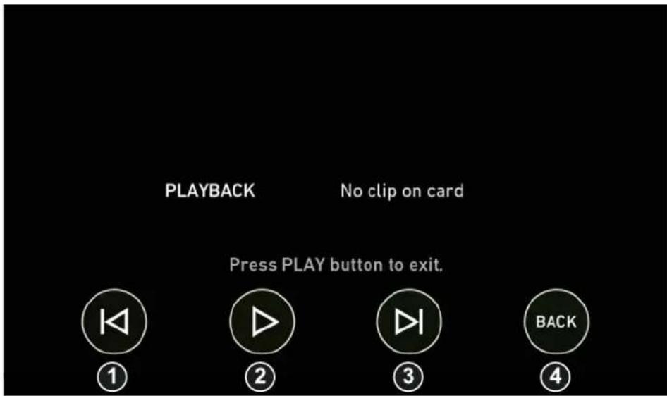
▶ Play or pause clip by pressing the "Play" (2) touch icon on the monitor.
▶ Skip to previous or to next clip by pressing the "Skip previous" (1) or "Skip next" (3) touch icon on the monitor.
▶ Exit the playback menu by pressing the "BACK" (3) touch icon on the monitor.
Note: The playback menu is not available during recording.
25 Licensing and updating
25.1 Camera update
Tools needed
- ALEXA Mini with connected MVF-1
- Fully charged camera battery
- Computer with internet access and USB interface
- USB stick (FAT 32 file format), prepared for use with ALEXA Mini
Update procedure
The camera supports the installation of SUP software update packages. Check www.arri.com for the latest available SUP version.
- Via computer, download the software update package (SUP) from www.arri.com.
-
Doube-click on the downloaded file (*.zip) to unpack it:
-
Update file (*.SUP)
o Update key (*.lic)
o Release notes -
Read the release notes carefully.
-
Copy the update file (*.SUP) to the ARRI/A-MINI/SUP folder on the USB stick.
-
Copy the update key (*.lic) to ARRI/A-MINI/LICENSES on the USB stick.
-
Safely remove the USB stick from the computer.
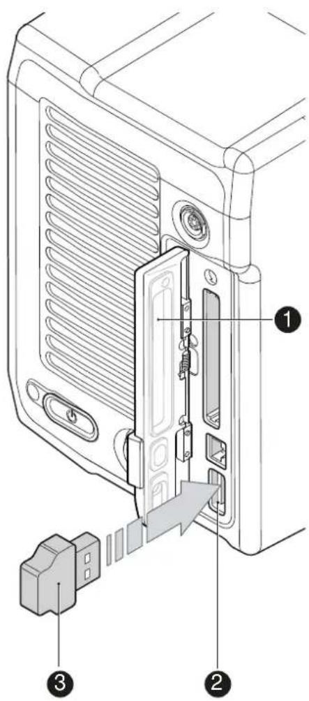
- Open the media lid (1) and connect the USB stick (3) to the camera (2).
- Remove the CFast card from the camera.
- Switch on the camera with a full battery.
- From the home screen, navigate to MENU > System > Camera update:
MENU > System > Camera update
Note: Update only possible with the CFast card removed from the camera.
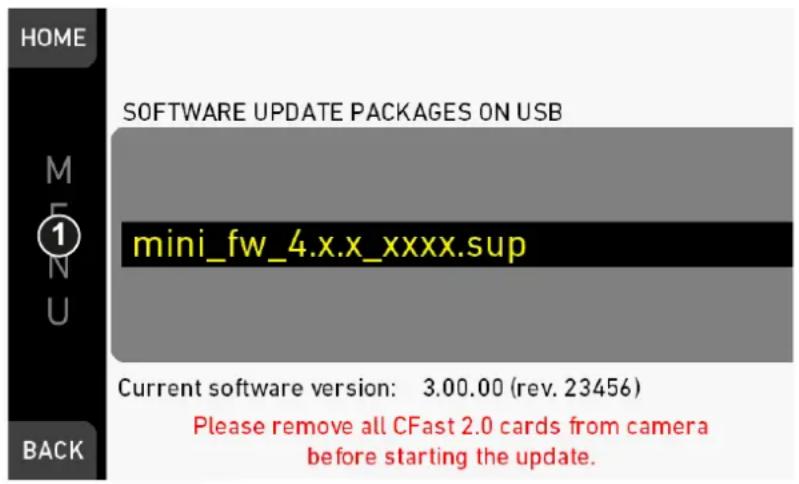
- Scroll to the required update file and press the jogwheel (1).
- Press CONFIRM (1) to start the update. Cancel with BACK.
Note: Never shut down the camera or unplug power during the update.
- Check the MVF-1 for the update progress.
- Wait for the update process to finish and the camera to reboot.
After a successful update and reboot, the camera monitor displays a blue success message.
- If so: Press CLOSE to start using your updated camera.
Note: After an update, the timezone and daylight saving time settings of the camera are reset. Please set them accordingly in the menu (MENU>System>System time + date).
A failed update produces a red warning message. However, previous camera software remains intact.
- If so: Press CLOSE, restart the camera and start the update again.
25.2 Licensing
You can further enhance the camera capabilities through licensed features available from the ARRI license shop at http://alshop.arri.de.
License keys are linked to each camera's serial number and cannot be transferred from one camera to another.
The ARRI license webshop requires a hardware info file (*.json) to identify the individual camera.
Before ordering a license key, you must export the HW INFO file from the camera to a USB memory stick for upload during purchase.
NOTICE
Licenses are also available as temporary real-time licenses. After installation, the license is valid for a defined period past the installation time. After this period, the license becomes invalid.
A temporary license shows Valid until: YY-MM-DD HH:MM:SS (1) in the licensed features screen and in the FEATURES subscreen.
The active camera license model (incl. contained features) is available under: Menu > System > Licensed feature (1) and (2).
25.2.1 Extracting HW INFO from the camera
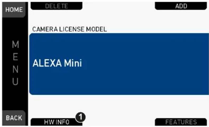
- Prepare a USB memory stick. See page 27.
- Connect the memory stick to the camera.
- Navigate to Menu > System > Licensed features.
- Press HW INFO (1).
- In the next screen, click CONFIRM.
- The file is saved in the USB folder ARRI/ARRI Mini/LICENSES.
- File name is A-MINI-HW-#####-YYMMDD-HHMM.json*
- Copy the file from USB to a computer, easily accessible when ordering licenses.
* ###### = camera serial number. YYMMDD-HHMM = date/time stamp.
25.2.2 Installing a license file
| NOTICE |
| Keep backup copies of all license files in case a license deleted from the camera must be re-installed. |
| Installed licenses remain on the camera, independent of USB memory stick, and across the installation of SUP software update packages. |
| All installed licenses are displayed at MENU >System > Licensed features > FEATURES. |
Menu > System > Licensed features
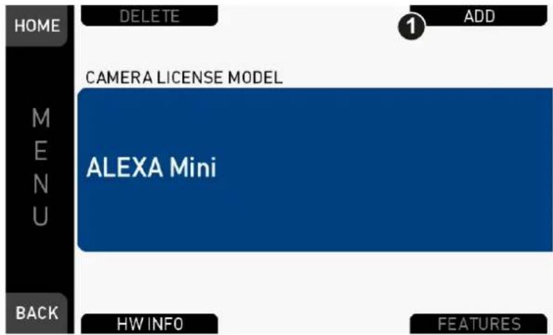
- Copy the license file into the ARRI/ARRI Mini/LICENSES folder on a correctly prepared USB stick. See page 27.
- Connect the USB stick to the camera.
- Via jogwheel, open Menu > System > Licensed features.
- Press ADD (1).
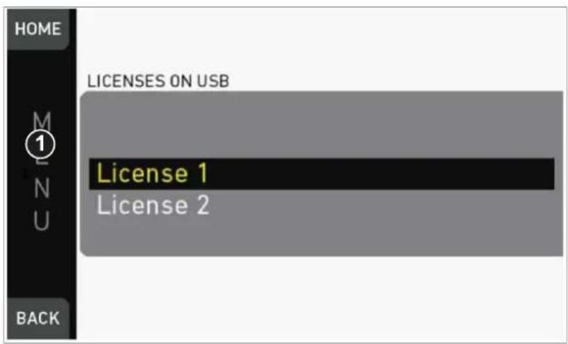
- A list appears.
- Via jogwheel (1) scroll to the required file.
- Confirm by pressing the wheel (1).
- Wait for the file to install.
- Reboot the camera afterwards.
- If required: Repeated for other files.
25.2.3 Deleting a license
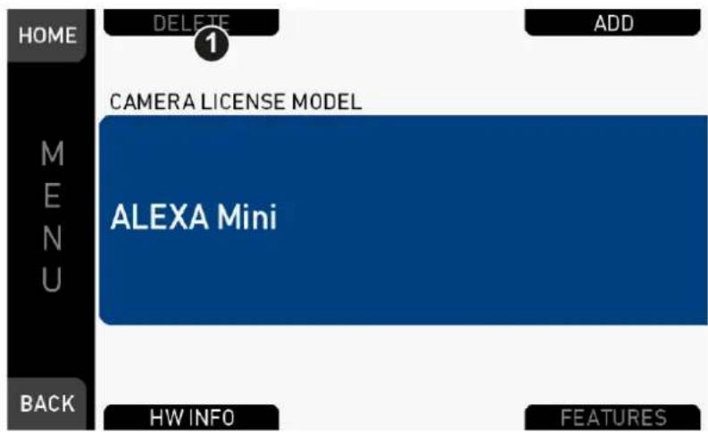
-
Open the License menu.
-
Press DELETE (1).
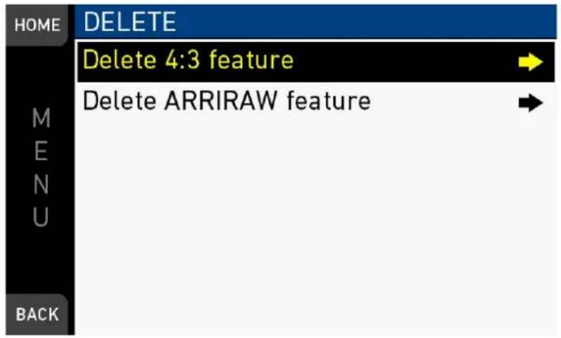
- Select the feature you want to delete.
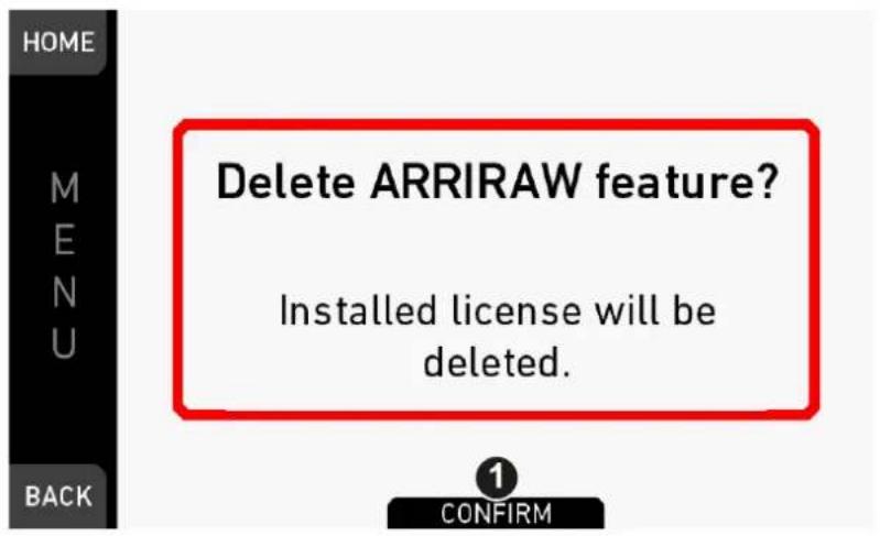
- Press CONFIRM (1). Cancel with BACK.
A green message confirms the successful deleted license.
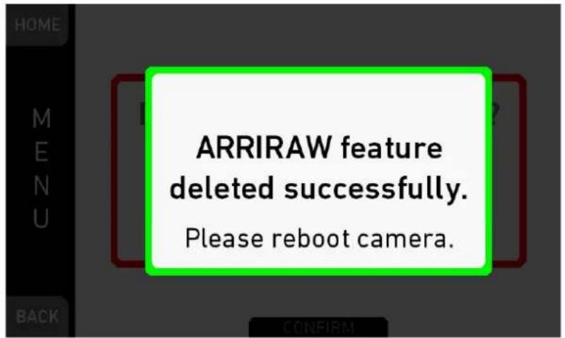
26 Appendix
26.1 Technical data
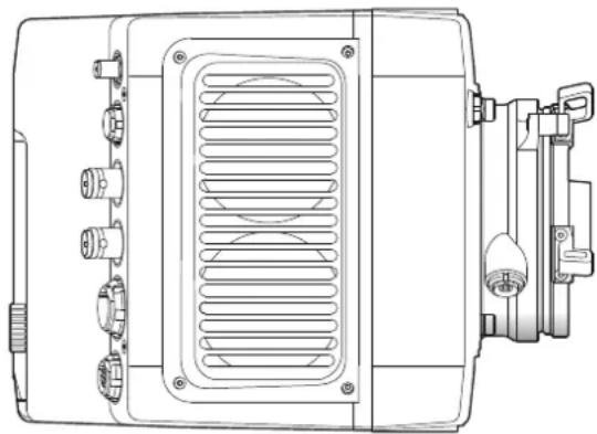
natural_image
Technical line drawing of an electric motor or generator unit with cooling fins and mounting brackets (no text or symbols)Camera info
| Dimensions Length | 185 mm |
| Height | 140 mm |
| Width | 125 mm |
Weight 2.3 kg / 5 lbs (camera body with titani-
um PL mount)
Sensor 35 mm format ARRI ALEV III CMOS
| with Bayer pattern color filter array | ||
| Sensor photo sites | ProRes: | Resolution: |
| S16 HD | 1600x900 | |
| HD | 1920x1080 | |
| HD Ana. | 1920x2160 | |
| 2K | 2867x1613 | |
| 2.39:1 2K Ana. | 2560x2145 | |
| 3.2K | 3200x1800 | |
| 4K UHD | 3200x1800 | |
| 4:3 2.8K | 2880x2160 | |
| ARRIRAW: | ||
| 2.8K | 2880x1620 | |
| Open Gate 3.4K | 3424x2202 | |
| 4:3 2.8K (OG 3.4K) | 2880x2160 | |
| 16:9 HD Ana. (OG 3.4K) | 1920x2160 | |
| 2.39:1 2K Ana. (OG 3.4K) | 2560x2145 | |
Shutter Electronic shutter, 5.0°-356.0°
Exposure latitude 14+ stops over the entire sensitivity
range from EI 160 to EI 3200 as measured with the ARRI Dynamic Range Test Chart (DRTC-1)
Exposure index adjustable from EI 160-3200 in 1/3
stops
EI 800 base sensitivity
ND filters Built-in motorized ND filters 0.6, 1.2,
2.1
supported Lens mounts
Steel PL mount with ENG connector and LDS
Titanium PL mount with L-Bus connector and LDS
EF mount PL mount with Hirose connector and LDS
B4 mount with Hirose connector
Recording media CFast 2.0 memory cards
Sound level < 20 dB(A) at standard frame rates
Environmental -20°C to +50°C (-4°F to +122°F) @
95% r.h. non-condensing
Splash and dust-proof through sealed electronics
Wireless interfaces
Built-in WiFi and white radio modules
Recording info
| Target resolutions | ProRes: | Resolution: |
| S16 HD | 1920x1080 | |
| HD | 1920x1080 | |
| HD Ana. | 1920x1080 | |
| 2K | 2048x1152 | |
| 2.39:1 2K Ana. | 2048x858 | |
| 3.2K | 3200x1800 | |
| 4K UHD | 3840x2160 | |
| 4:3 2.8K | 2944x2160 | |
| ARRIRAW: | ||
| 2.8K | 2880x1620 | |
| OpenGate 3.4K | 3424x2202 | |
| 4:3 2.8K (OG 3.4K) | 3424x2202 | |
| 16:9 HD Ana. (OG 3.4K) | 3424x2202 | |
| 3424x2202 |
2.39:1 2K Ana.
(OG 3.4K)
Recording
codecs
ProRes 422 LT, 422, 422 HQ, 4444,
4444 XQ
ARRIRAW
Maximum recording frame rates
Camera settings Maximum frame rate in fps
| Resolution Codec CFAST 2.0 60 | GB | CFAST 2.0 128 GB | |
| S16 HD ProRes 422 LT | 200 | 200 | |
| ProRes 422 | 200 | 200 | |
| ProRes 422 HQ | 200 | 200 | |
| ProRes 4444 | 137 | 200 | |
| ProRes 4444 XQ | 91 | 120 | |
| HD ProRes 422 LT | 200 | 200 | |
| ProRes 422 | 200 | 200 | |
| ProRes 422 HQ | 200 | 200 | |
| ProRes 4444 | 137 | 200 | |
| ProRes 4444 XQ | 91 | 120 | |
| HD Ana. ProRes 422 LT | 120 | 120 | |
| ProRes 422 | 120 | 120 | |
| ProRes 422 HQ | 120 | 120 | |
| ProRes 4444 | 120 | 120 | |
| ProRes 4444 XQ | 120 | 120 | |
| 2K ProRes 422 LT | 200 | 200 | |
| ProRes 422 | 200 | 200 | |
| ProRes 422 HQ | 181 | 200 | |
| ProRes 4444 | 120 | 200 | |
| ProRes 4444 XQ | 80 | 120 | |
| 2.39:1 2K Ana. ProRes 422 LT | 120 | 120 | |
| ProRes 422 | 120 | 120 | |
| ProRes 422 HQ | 120 | 120 | |
| ProRes 4444 | 120 | 120 | |
| ProRes 4444 XQ | 120 | 120 | |
| 3.2K ProRes 422 LT | 60 | 60 | |
| ProRes 422 | 60 | 60 | |
| ProRes 422 HQ | 60 | 60 | |
| ProRes 4444 | 49 | 60 | |
| ProRes 4444 XQ | 30 | 60 | |
4K UHD ProRes 422 LT 60 60
ProRes 422 60 60
ProRes 422 HQ 51 60
ProRes 4444 34 60
ProRes 4444 XQ 22 30
4:3 2.8K ProRes 422 LT 50 50
ProRes 422 50 50
ProRes 422 HQ 50 50
ProRes 4444 50 50
ProRes 4444 XQ 45 45
2.8K ARRIRAW 30 48
OpenGate 3.4K ARRIRAW 30 30
4:3 2.8K (OG ARRIRAW 30 30
3.4K)
16:9 HD Ana. ARRIRAW 30 30
(OG 3.4K)
2.39:1 2K Ana. ARRIRAW 30 30
(OG 3.4K)
Electrical data
DC power input 10.5 to 34 V
Operation temperature -20 to +45°C (-4 to +113 °F)
Audio data
External interfaces 1x 5-pin LEMO
Input formats Balanced stereo line
Recording format (embedded in video file) Linear PCM, 24 bit 48 kHz
Number of recording channels 2/5 (used/recorded)
Gain adjustment 0 - +30 dB independently per input
Line input max. level +24 dBu, correlating to 0 dBFS
Limiter/Auto level features -6 dBFS threshold
3ms attack time
360ms release time
∞:1 ratio
Metering From -50 to 0 dBFS
Markers at -20, -18 and -9 dBFS
Warnings from -5 dBFS (yellow) and -2 dBFS (red) to 0 dBFS
Input clipping indication through red frame around audio meter
Internal test tone generator 1 kHz sine @ -9 dBFS / -18 dBFS / -20
dBFS
26.2 Dimensional drawings
Dimensional drawings are attached at the end of this document. They can also be downloaded from the ARRI website:
https://www.arri.com/alexamini
26.3 Pin-outs
Note: All pin-outs for camera interfaces appear as seen by the user.
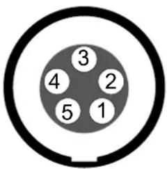
Audio
ARRI offers a cable with a matching connector to create audio adapters. The following table shows the wire assignments of this cable.
Function Wire
Gnd Shield
Line 1 (+) White with blue ring
Line 1 (-) Blue with white ring
Line 2 (+) White
Line 2 (-) Blue
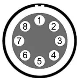
BAT
ENG (on PL lens mount steel)
Connector ID: Hirose HR10-10R-12S(73)
1 -/-
2 -/-
3 Gnd
4 -/-
5 -/-
6 12 V
7 -/-
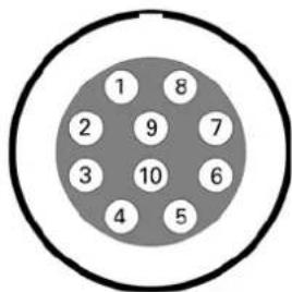
8 -/-
9 -/-
10 -/-
11 RXD (Mount to Lens)
12 TXD (Lens to Mount)
Ethernet
Connector ID: LEMO EEG.1B.310
1 MX-1P CTS (white-orange)
2 MX-1N DTR (orange)
3 MX-2P GND (white-green)
4 MX-2N DCD (green)
5 MX-3P TXD (blue)
6 MX-3N RXD (white-blue)
7 MX-4P DSR (white-brown)
8 MX-4N RTS (brown)
9 Gnd
10 Propietary - do not use
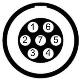
EXT
Connector ID: LEMO EEG.1B.307
1 Can1 H
2 Can1 L
3 Can2 H
4 Can2 L
6 Gnd
7 R/S
5 VBat (1A max)
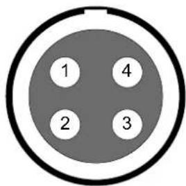
LBUS (on PL lens mount titanium)
Connector ID: LEMO EEG.0B.304
1 Gnd
2 Can L
3 VBat
4 Can H
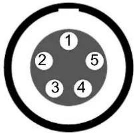
Timecode
Connector ID: LEMO EEG.0B.305
1 Gnd
2 LTC in
3 - (no tuning)
4 - (no tuning)
5 LTC out
26.4 Declarations of conformity
EC Declaration of Conformity
The product ALEXA Mini conforms with the specifications of following European directives:
- Directive 2014/30/EU of the European parliament and the Council of 26 February 2014 on the harmonization of the laws of the Member States relating to electromagnetic compatibility
- Directive 1999/5/EC of the European Parliament and the Council of 9 March 1999 on radio equipment and telecommunications terminal equipment and the mutual recognition of their conformity
- Directive 2011/65/EU of the European Parliament and the Council of 8 June 2012 on the restriction of the use of certain hazardous substances in electrical and electronic equipment
FCC Compliance Statement
Class A Statement: This equipment has been tested and found to comply with the limits for a Class A digital device, pursuant to Part 15 of the FCC Rules. These limits are designed to provide reasonable protection against harmful interference when the equipment is operated in a commercial environment.
Note: This equipment generates, uses, and can radiate radio frequency energy and, if not installed and used in accordance with the instruction manual, may cause harmful interference to radio communications. Operation of this equipment in a residential area is likely to cause harmful interference in which case the user will be required to correct the interference at his own expense.
Industry Canada Compliance Statement
Complies with the Canadian ICES-003 Class A specifications.
This device complies with RSS-210 of Industry Canada.
This Class A device meets all the requirements of the Canadian interference-causing equipment regulations
ALEXA Mini
ALEXA Mini (camera body with titanium PL lens mount)
| Length | Width | Height | Weight |
| 184.75 mm - 7.27" | 124.83 mm - 4.91" | 140 mm - 5.5" | ~ 2.3 kg/5 lbs |
Camera Left
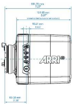
Camera Top
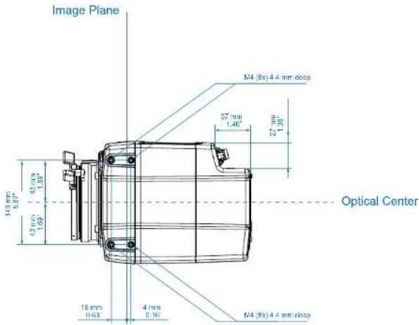
ALEXA Mini
ALEXA Mini (camera body with titanium PL lens mount)
| Length | Width | Height | Weight |
| 184.75 mm - 7.27" | 124.83 mm - 4.91" | 140 mm - 5.5" | ~ 2.3 kg/5 lbs |


- Software Update Packet 4.0
- Imprint
- Copyright
- For further assistance
- Contents
- Camera menu....97
- MENU > Recording....98
- Recording Codec....98
- ARRIRAW....98
- Resolution....99
- 4:3 Recording....99
- Project settings.... 100
- Project rate.... 100
- Next reel count.... 101
- Camera Index....101
- Camera ID prefix....101
- Lens squeeze factor....101
- Record mode.... 102
- Rec beeper / tally.... 103
- Pre-recording.... 103
- How to activate pre-recording.... 104
- Pre-recording maximum duration.... 104
- Audio recording.... 105
- MENU > Media.... 106
- Erase CARD....106
- Delete last clip....108
- Prepare USB medium.... 109
- MENU > Monitoring.... 112
- EVF/Monitor.... 112
- Surround view....112
- Zoom position.... 113
- Exposure tool....113
- Peaking....114
- Settings.... 115
- EVF overlays / Monitor overlays / SDI overlays.... 115
- SDI....117
- Frame lines....120
- Setting/adding a frame line.... 122
- Deleting a frame line.... 125
- User rectangle 1 & 2.... 126
- Color bars.... 126
- MENU > System....127
- Sensor....127
- Fan mode.... 128
- DANGER!
- WARNING!
- CAUTION!
- NOTICE
- High voltage! Risk of electric shock and fire!
- 危险
- Condensation! Risk of electric shock and fire!
- 小心
- Heavy weight! Risk of injury and damage!
- ⚠ 小心
- General precautions / 般安全措施
- 提示
- Audience and intended use
- Scope of delivery and warranty
- Delivery
- Warranty
- Camera layout
- Product identification
- Power supply
- Switching on/off
- To switch on the camera:
- To switch off the camera:
- To check the recording status
- Connectors
- Front connectors
- I/O panel
- TC (5-pin LEMO)
- White radio antenna
- EVF (16-Pin ODU)
- SDI OUT 1 & 2 (BNC)
- BAT (8-pin LEMO)
- EXT (7-pin LEMO)
- ETH (10-pin LEMO)
- Media panel
- USB
- Preparing a USB memory stick
- Changing a CFast 2.0 card
- Lens mount/filters
- Cooke /i support
- ND filter module
- Changing a lens
- PL mount
- EF mount
- Lens control
- Manual iris adjustment
- Iris control via user button
- Auto iris
- Camera controls
- Function button FN and camera buttons 1-3
- Camera buttons as user buttons:
- Camera buttons to control standard camera functions:
- Overlay menu
- Recording button
- To start recording:
- MVF-1 controls
- Proximity sensor
- EVF image/monitor
- MVF-1 buttons
- PK peaking button
- EXP exposure tool button
- VF1 & VF2 user buttons
- PLAY button
- Playback screen controls
- CLIPLIST
- OPTIONS
- Diopter adjustment
- Adjusting the monitor
- Changing the monitor mode
- Live monitor
- Surround mask
- Center mark
- User monitor
- Adjusting the monitor brightness
- Overlay menu
- Camera buttons
- MVF-1
- Web remote
- HOME
- NETWORK INFO
- BACK
- Home screen
- MENU jogwheel
- ALERT message button
- FPS button
- TC button
- SHUTTER button
- INFO button
- EI button
- LOOK button
- WB button
- Status section
- WiFi, CAL and LDS icons
- Temperature icon
- Fan icon
- USB icon
- Camera icon
- GEN icon
- Audio meters
- Codec/Resolution
- Camera status
- Card status
- Recording status
- BAT
- ALERT messages
- Info screens
- Version info
- SN: Serial number of lens.
- User button info
- Export HW info file
- Export logfiles
- Export update logfiles
- Export user manual
- FPS settings
- Setting/adding an FPS value
- Deleting an FPS value
- TC settings
- TC options
- Run mode
- Mode
- Regen source
- Count mode
- TC Offset
- SHUTTER settings
- Selecting a SHUTTER unit
- Note: How to adjust the shutter for filming a monitor
- Setting/adding a SHUTTER value
- Deleting a SHUTTER value
- WB settings
- Setting/adding a WB value
- Renaming a WB value
- Deleting a WB value
- WB Options
- LOOK and gamma settings
- Setting the LOOK file
- Setting Gamma
- Log C
- LOOK
- Adding a LOOK file
- Deleting a LOOK file
- Exporting a LOOK file
- Duplicating/renaming a LOOK file
- LOOK parameters
- ASC CDL Transforms
- Slope
- Offset
- Power
- (Log) Saturation
- 3D LUT and video look parameters
- Knee
- Black gamma
- Gamma
- (Video) Saturation
- Saturation by Hue
- LOOK editing
- EI settings
- EI technical details
- Camera menu
- MENU > Recording
- Recording Codec
- ARRIRAW
- Resolution
- MENU > Recording > Resolution
- S16 HD Resolution
- 4:3 Recording
- Project settings
- Project rate
- MENU > Recording > Project settings > Project rate
- Next reel count
- Camera Index
- Camera ID prefix
- Lens squeeze factor
- Record mode
- Normal
- Interval recording
- Stop motion
- Interval recording parameters
- Interval length
- Burst length
- Duration mode
- Recording duration
- Resulting clip length
- Stop motion beeper
- Rec beeper / tally
- Pre-recording
- How to activate pre-recording
- Pre-recording maximum duration
- ProRes 4444 buffer durations
- ProRes 422 HQ/422/422 LT buffer durations
- Audio recording
- MENU > Media
- Erase CARD
- Delete last clip
- Prepare USB medium
- MENU > Monitoring
- EVF/Monitor
- Surround view
- Zoom position
- Exposure tool
- Peaking
- Settings
- EVF overlays / Monitor overlays / SDI overlays
- SDI
- Frame lines
- Setting/adding a frame line
- Deleting a frame line
- User rectangle 1 & 2
- Color bars
- MENU > System
- Sensor
- Fan mode
- Power
- System time + date
- Buttons + display
- Network / WiFi
- Camera update
- MENU > Setup
- MENU > User buttons
- User/VF button functions
- MENU > Metadata
- MENU > Electronic Control System (ECS)
- Radio
- Lens data
- MENU > Electronic Control System (ECS) > Lens data
- Favorites list
- LDA and WCU-4
- Calibrate all motors
- Lens motor focus
- Camera preparation
- Adjusting the MVF-1
- Mounting to a bridge plate
- Assembly and retrofits
- MVF-1 and EVF cable
- Camera handle
- Tool needed
- Antenna
- Changing a lens mount
- Tools and provisions needed
- Installation (here: a PL mount)
- Condensation! Risk of electric shock and damage!
- CCP-1
- Transvideo StarliteHD5-ARRI Monitor
- User menu
- Control menu
- Playback menu
- Licensing and updating
- Camera update
- Tools needed
- Update procedure
- Licensing
- Extracting HW INFO from the camera
- Installing a license file
- Menu > System > Licensed features
- Deleting a license
- Appendix
- Technical data
- Electrical data
- Audio data
- Dimensional drawings
- Pin-outs
- Audio
- Function Wire
- ENG (on PL lens mount steel)
- Ethernet
- EXT
- LBUS (on PL lens mount titanium)
- Timecode
- Declarations of conformity
- EC Declaration of Conformity
- FCC Compliance Statement
- Industry Canada Compliance Statement
Brand : ARRI
Model : ALEXA Mini
Category : Camera