 — Car — Mode d'emploi PDF")
RAV4 Hybrid (2021) - Car TOYOTA - Free user manual and instructions
Find the device manual for free RAV4 Hybrid (2021) TOYOTA in PDF.

| Product type | 5-door hybrid car |
| Dimensions (L x W x H) | 4600 x 1855 x 1685 mm |
| Wheelbase | 2690 mm |
| Curb weight | 1635 kg (2WD version) |
| Internal combustion engine | 4-cylinder 2.5 L petrol, Atkinson cycle |
| Electric motor | Permanent magnet synchronous |
| Maximum combined power | 219 hp (163 kW) |
| Transmission | CVT (continuously variable transmission) with sequential mode |
| Drivetrain | Front (2WD) or all-wheel (AWD-i) |
| Battery type | Nickel-metal hydride (Ni-MH) battery |
| Battery capacity | 1.6 kWh |
| Combined consumption (WLTP) | 4.5 L/100 km |
| CO2 emissions (WLTP) | 102 g/km |
| Fuel tank | 55 L |
| Fuel | Unleaded petrol 95 or 98 + regenerative braking charging |
| Main features | Self-charging hybrid, energy regeneration, Toyota Safety Sense (pre-collision, adaptive cruise control, lane departure alert, etc.) |
| Maintenance and cleaning | Engine oil change every 15,000 km or 1 year; cabin filter every 2 years; hybrid battery check at dealership |
| Safety | Front, side and curtain airbags; ABS, ESP, hill start assist |
| Spare parts and repairability | Tires 225/65 R17; front brake pads specific to hybrid; auxiliary 12V battery |
| General information | 752-page manual available as PDF download |
Frequently Asked Questions - RAV4 Hybrid (2021) TOYOTA
User questions about RAV4 Hybrid (2021) TOYOTA
0 question about this device. Answer the ones you know or ask your own.
Ask a new question about this device
Download the instructions for your Car in PDF format for free! Find your manual RAV4 Hybrid (2021) - TOYOTA and take your electronic device back in hand. On this page are published all the documents necessary for the use of your device. RAV4 Hybrid (2021) by TOYOTA.
USER MANUAL RAV4 Hybrid (2021) TOYOTA
Search by illustration
| For safety and security | Make sure to read through them(Main topics: Child seat, theft deterrent system) | 1 |
| Vehicle status information and indicators | Reading driving-related information(Main topics: Meters, multi-information display) | 2 |
| Before driving | Opening and closing the doors and windows, adjustment before driving(Main topics: Keys, doors, seats) | 3 |
| Driving | Operations and advice which are necessary for driving(Main topics: Starting hybrid system, refueling) | 4 |
| Audio | Operating the Audio(Main topics: Audio/visual, phone, Connected Services) | 5 |
| Interior features | Usage of the interior features(Main topics: Air conditioner, storage features) | 6 |
| Maintenance and care | Caring for your vehicle and maintenance procedures(Main topics: Interior and exterior, light bulbs) | 7 |
| When trouble arises | What to do in case of malfunction and emergency(Main topics: 12-volt battery discharge, flat tire) | 8 |
| Vehicle specifications | Vehicle specifications, customizable features(Main topics: Fuel, oil, tire inflation pressure) | 9 |
| For owners | Reporting safety defects for U.S. owners, and seat belt and SRS airbag instructions for Canadian owners | 10 |
| Index | Search by symptom | |
| Search alphabetically |
For your information...... 8
Reading this manual....13
How to search......14
Pictorial index ......16
1 For safety and security
1-1. For safe use
Before driving....28
For safe driving .....29
Seat belts....31
SRS airbags....35
Front passenger occupant classification system .....45
Exhaust gas precautions..50
1-2. Child safety
Riding with children......51
Child restraint systems.....52
1-3. Emergency assistance
Safety Connect ......67
1-4. Hybrid system
Hybrid system features ....72
Hybrid system precautions 76
1-5. Theft deterrent system
Immobilizer system .....81
Alarm....84
2 Vehicle status information and indicators
2-1. Instrument cluster
Warning lights and indicators 88
Gauges and meters (with 4.2-inch display) .....94
Gauges and meters (with 7-inch display) .....98
Multi-information display 103
Energy monitor/consumption screen.... 113
3 Before driving
3-1. Key information
Keys 120
3-2. Opening, closing and locking the doors
Side doors 127
Back door 133
Smart key system...... 147
3-3. Adjusting the seats
Front seats 153
Rear seats......154
Driving position memory 156
Head restraints...... 159
3-4. Adjusting the steering wheel and mirrors
Steering wheel...... 162
Inside rear view mirror... 163
Digital Rear-view Mirror. 165
Outside rear view mirrors 174
3-5. Opening, closing the windows and moon roof
Power windows ...... 176
Moon roof 179
Panoramic moon roof.... 182
4 Driving
4-1. Before driving
Driving the vehicle...... 189
Cargo and luggage ..... 196
Vehicle load limits ..... 199
Trailer towing 200
Dinghy towing 209
4-2. Driving procedures
Power (ignition) switch (vehicles without smart key system).... 210
Power (ignition) switch (vehicles with smart key system) 212
EV drive mode ...... 217
Hybrid transmission ..... 219
Turn signal lever ...... 223
Parking brake.... 224
Brake Hold 227
4-3. Operating the lights and wipers
Headlight switch...... 229
AHB (Automatic High Beam) 232
Fog light switch 235
Windshield wipers and washer.... 236
Rear window wiper and washer.... 239
4-4. Refueling
Opening the fuel tank cap 241
4-5. Using the driving support systems
Toyota Safety Sense 2.0244
PCS (Pre-Collision System) 250
LTA (Lane Tracing Assist) 258
RSA (Road Sign Assist) 268
Dynamic radar cruise control with full-speed range ... 271
BSM (Blind Spot Monitor) 282
Intuitive parking assist... 291
PKSB (Parking Support Brake).... 298
Parking Support Brake function (static objects) ..... 303
Parking Support Brake function (rear-crossing vehicles) 309
Rear view monitor system 313
Toyota parking assist monitor 321
Panoramic view monitor 334
Driving mode select switch 366
Trail Mode 367
Driving assist systems... 369
4-6. Driving tips
Hybrid vehicle driving tips 376
Winter driving tips...... 378
Utility vehicle precautions 381
5 Audio
5-1. Basic function
Buttons overview...... 387
Menu screen...... 389
Status icon 390
"Setup" screen 392
5-2. Basic information before operation
Initial screen.... 393
Touch screen 394
Home screen.... 396
Entering letters and numbers/list screen operation 397
Screen adjustment ..... 400
Linking multi-information display and the system .... 401
5-3. Connectivity settings
Registering/Connecting a Bluetooth® device ..... 402
Setting Bluetooth ^® details 406
Wi-Fi ^® Hotspot 414
5-4. Apple CarPlay/Android Auto
Apple CarPlay ^® /Android Auto ^TM 419
5-5. Other settings
General settings...... 426
Voice settings...... 430
Vehicle settings...... 431
5-6. Using the audio/visual system
Quick reference...... 432
Some basics 433
5-7. Radio operation
AM/FM/SiriusXM (SXM) radio 437
5-8. Media operation
USB memory...... 444
iPod/iPhone (Apple CarPlay) 446
Android Auto...... 449
Bluetooth ^® audio ..... 450
5-9. Audio/visual remote controls
Steering switches ..... 454
5-10. Audio settings
Setup...... 456
5-11. Tips for operating the audio/visual system
Operating information.... 458
5-12. Voice command system operation
Voice command system 470
Command list 473
5-13.Mobile Assistant operation
Mobile Assistant 477
5-14. Phone operation (Hands-free system for cellular phones)
Quick reference...... 479
Some basics...... 480
Placing a call using the Bluetooth® hands-free system 484
Receiving a call using the Bluetooth®hands-free system 487
Talking on the Bluetooth ^® hands-free system..... 488
Bluetooth ^® phone message function.... 490
5-15.Phone settings
Setup...... 495
5-16.What to do if...
(Bluetooth®)
Troubleshooting ..... 505
5-17. Connected Services overview
Connected Services..... 509
Type A: Function achieved by using a smartphone or DCM 510
Type B: Function achieved by using DCM and the system 512
Type C: Function achieved by using DCM.... 513
Type D: Function achieved by using DCM and a smartphone 516
5-18. Connected Services operation
Toyota Apps.... 518
5-19.Setup
Toyota Apps settings .... 522
6 Interior features
6-1. Using the air conditioning system and defogger
Automatic air conditioning system.... 524
Heated steering wheel/seat heaters/seat ventilators531
6-2. Using the interior lights
Interior lights list ...... 534
6-3. Using the storage features
List of storage features . 537
Luggage compartment features 541
6-4. Using the other interior features
Other interior features ... 546
Garage door opener ..... 557
7 Maintenance and care
7-1. Maintenance and care
Cleaning and protecting the vehicle exterior .... 566
Cleaning and protecting the vehicle interior .... 569
7-2. Maintenance
Maintenance requirements 572
General maintenance.... 573
Emission inspection and maintenance (I/M) programs 576
7-3. Do-it-yourself maintenance
Do-it-yourself service precautions.... 577
Hood.... 579
Positioning a floor jack .. 580
Engine compartment ..... 582
12-volt battery...... 588
Tires 590
Tire inflation pressure.... 605
Wheels 607
Air conditioning filter..... 609
Cleaning the hybrid battery (traction battery) air intake vent and filter...... 611
Wiper insert replacement 615
Wireless remote control/electronic key battery...... 618
Checking and replacing fuses 621
Light bulbs.... 624
8 When trouble arises
8-1. Essential information
Emergency flashers ..... 634
If your vehicle has to be stopped in an emergency 635
If the vehicle is trapped in rising water.... 636
8-2. Steps to take in an emergency
If your vehicle needs to be towed.... 637
If you think something is wrong 641
If a warning light turns on or a warning buzzer sounds 642
If a warning message is displayed.... 654
If you have a flat tire..... 658
If the hybrid system will not start 667
If you lose your keys ..... 668
If the fuel filler door cannot be opened 669
If the electronic key does not operate properly (vehicles with smart key system) 670
If the 12-volt battery is discharged 672
If your vehicle overheats 677
If the vehicle becomes stuck 680
9 Vehicle specifications
9-1. Specifications
Maintenance data (fuel, oil level, etc.).... 684
Fuel information...... 694
Tire information ...... 696
9-2. Customization
Customizable features... 706
9-3. Initialization
Items to initialize...... 718
10 For owners
10-1. For owners
Reporting safety defects for U.S. owners.... 720
Seat belt instructions for Canadian owners (in French).... 721
SRS airbag instructions for Canadian owners (in French).... 722
Index
What to do if... (Trouble-shooting) 732
Alphabetical Index ..... 735
For your information
Main Owner's Manual
Please note that this manual applies to all models and explains all equipment, including options. Therefore, you may find some explanations for equipment not installed on your vehicle.
All specifications provided in this manual are current at the time of printing. However, because of the Toyota policy of continual product improvement, we reserve the right to make changes at any time without notice.
Depending on specifications, the vehicle shown in the illustrations may differ from your vehicle in terms of equipment.
Noise from under vehicle after turning off the hybrid system
Approximately five hours after the hybrid system is turned off, you may hear sound coming from under the vehicle for several minutes. This is the sound of a fuel evaporation leakage check and, it does not indicate a malfunction.
Accessories, spare parts and modification of your Toyota
A wide variety of non-genuine spare parts and accessories for Toyota vehicles are currently available in the market. You should know that Toyota does not warrant these products and is not responsible for their performance, repair, or replacement, or for any damage they may cause to, or adverse effect they may have on, your Toyota vehicle.
This vehicle should not be modified with non-genuine Toyota products. Modification with non-genuine Toyota products could affect its performance, safety or durability, and may even violate governmental regulations. In addition, damage or performance problems resulting from the modification may not be covered under warranty.
Installation of a mobile two-way radio system
The installation of a mobile two-way radio system in your vehicle could affect electronic systems such as:
- Hybrid system
- Multiport fuel injection system/sequential multiport fuel injection system
● Toyota Safety Sense 2.0
- Anti-lock brake system
- SRS airbag system
- Seat belt pretensioner system
Be sure to check with your Toyota dealer for precautionary measures or special instructions regarding installation of a mobile two-way radio system.
High voltage parts and cables on the hybrid vehicles emit approximately the same amount of electromagnetic waves as the conventional gasoline powered vehicles or home electronic appliances despite of their electromagnetic shielding.
Unwanted noise may occur in the reception of the mobile two-way radio.
Vehicle data recording
The vehicle is equipped with sophisticated computers that will record certain data, such as:
• Engine speed/ Electric motor speed (traction motor speed)
- Accelerator status
- Brake status
- Vehicle speed
• Operation status of the driving assist systems
- Images from the cameras
Your vehicle is equipped with cameras. Contact your Toyota dealer for the location of recording cameras.
- Hybrid battery (traction battery) status
The recorded data varies according to the vehicle grade level and options with which it is equipped.
These computers do not record conversations or sounds, and only record images outside of the vehicle in certain situations.
● Data Transmission
Your vehicle may transmit the data recorded in these computers to Toyota without notification to you.
- Data usage
Toyota may use the data recorded in this computer to diagnose malfunctions, conduct research and development, and improve quality.
Toyota will not disclose the recorded data to a third party except:
- With the consent of the vehicle owner or with the consent of the lessee if the vehicle is leased
- In response to an official request by the police, a court of law or a government agency
- For use by Toyota in a lawsuit
- For research purposes where the data is not tied to a specific vehicle or vehicle owner
- Recorded image information can be erased by your Toyota dealer.
The image recording function can be disabled. However, if the function is disabled, data from when the system operates will not be avail-
able.
- To learn more about the vehicle data collected, used and shared by Toyota, please visit www.toyota.com/privacyvts/.
Usage of data collected through Safety Connect (U.S.mainland only)
If your Toyota has Safety Connect and if you have subscribed to those services, please refer to the Safety Connect Telematics Subscription Service Agreement for information on data collected and its usage.
- To learn more about the vehicle data collected, used and shared by Toyota, please visit www.toyota.com/privacyvts/
Event data recorder
This vehicle is equipped with an event data recorder (EDR). The main purpose of an EDR is to record, in certain crash or near crash-like situations, such as an air bag deployment or hitting a road obstacle, data that will assist in understanding how a vehicle's systems performed. The EDR is designed to record data related to vehicle dynamics and safety systems for a short period of time, typically 30 seconds or less.
The EDR in this vehicle is designed to record such data as:
● How various systems in your vehicle were operating;
- Whether or not the driver and passenger safety belts were buckled/fastened;
- How far (if at all) the driver was depressing the accelerator and/or brake pedal; and,
- How fast the vehicle was traveling.
These data can help provide a better understanding of the circumstances in which crashes and injuries occur.
NOTE: EDR data are recorded by your vehicle only if a non-trivial crash situation occurs; no data are recorded by the EDR under normal driving conditions and no personal data (e.g., name, gender, age, and crash location) are recorded. However, other parties, such as law enforcement, could combine the EDR data with the type of personally identifying data routinely acquired during a crash investigation.
To read data recorded by an EDR, special equipment is required, and access to the vehicle or the EDR is needed. In addition to the vehicle manufacturer, other parties, such as law enforcement, that have the special equipment, can read the
information if they have access to the vehicle or the EDR.
● Disclosure of the EDR data
Toyota will not disclose the data recorded in an EDR to a third party except when:
- An agreement from the vehicle's owner (or the lessee for a leased vehicle) is obtained
- In response to an official request by the police, a court of law or a government agency
- For use by Toyota in a lawsuit However, if necessary, Toyota may:
- Use the data for research on vehicle safety performance
- Disclose the data to a third party for research purposes without disclosing information about the specific vehicle or vehicle owner
Scrapping of your Toyota
The SRS airbag and seat belt pretensioner devices in your Toyota contain explosive chemicals. If the vehicle is scrapped with the airbags and seat belt pretensioners left as they are, this may cause an accident such as fire. Be sure to have the systems of the SRS airbag and seat belt pretensioner removed and disposed of by a qualified service shop or by your Toyota dealer before you scrap your vehicle.
Perchlorate Material
Special handling may apply, See www.dtsc.ca.gov/ hazardouswaste/perchlorate.
Your vehicle has components that may contain perchlorate. These components may include the airbags, seat belt pretensioners, wireless remote control batteries, and the batteries in the tire pressure warning valve and transmitters.

WARNING
■ General precautions while driving
Driving under the influence: Never drive your vehicle when under the influence of alcohol or drugs that have impaired your ability to operate your vehicle. Alcohol and certain drugs delay reaction time, impair judgment and reduce coordination, which could lead to an accident that could result in death or serious injury.
Defensive driving: Always drive defensively. Anticipate mistakes that other drivers or pedestrians might make and be ready to avoid accidents.
Driver distraction: Always give your full attention to driving. Anything that distracts the driver, such as adjusting controls, talking on a cellular phone or reading can result in a collision with resulting death or serious injury to you, your occupants or others.

WARNING
■General precaution regarding children's safety
Never leave children unattended in the vehicle, and never allow children to have or use the key.
Children may be able to start the vehicle or shift the vehicle into neutral. There is also a danger that children may injure themselves by playing with the side windows, the moon roof or the panoramic moon roof, or other features of the vehicle. In addition, heat build-up or extremely cold temperatures inside the vehicle can be fatal to children.
Reading this manual
Explains symbols used in this manual
Symbols in this manual
| Symbols | Meanings |
 | WARNING:Explains something that, if not obeyed, could cause death or serious injury to people. |
 | NOTICE:Explains something that, if not obeyed, could cause damage to or a malfunction in the vehicle or its equipment. |
| 123... | Indicates operating or working procedures.Follow the steps in numerical order. |
Symbols in illustrations
natural_image
Diagram showing a car interior with a highlighted vehicle and directional arrows indicating movement (no text or symbols)| Symbols | Meanings |
 | Indicates the action (pushing, turning, etc.) used to operate switches and other devices. |
 | Indicates the outcome of an operation (e.g. a lid opens). |
text_image
Diagram of car interior showing steering wheel, dashboard, and umbrella with no stop sign indicating no restriction| Symbols | Meanings |
 | Indicates the component or position being explained. |
 | Means Do not, Do not do this, or Do not let this happen. |
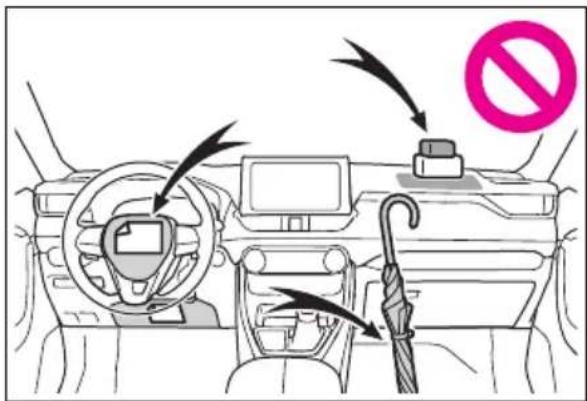
How to search
■Searching by name
● Alphabetical index: →P.735
text_image
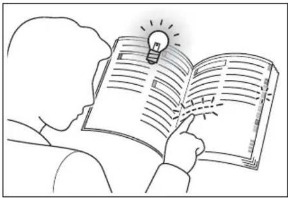
ABS? SRS?■Searching by installation position
- Pictorial index: P.16
natural_image
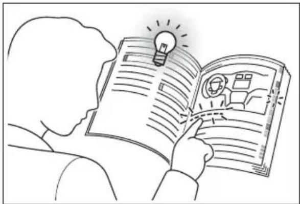
Line drawing of a person reading an open book with a lightbulb above it, no text or symbols present■Searching by symptom or sound
- What to do if... (Troubleshooting): →P.732
natural_image
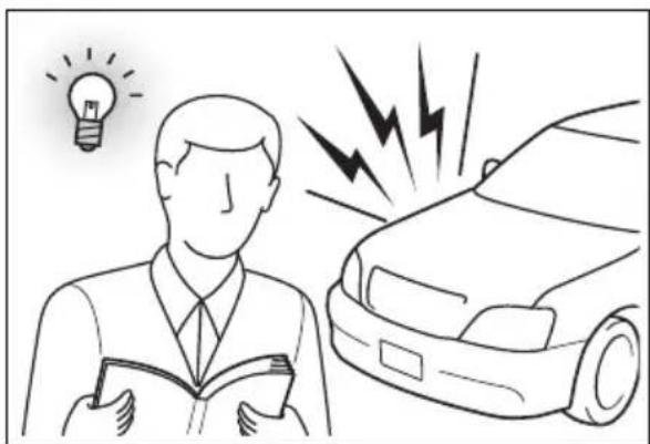
Illustration of a person reading a book with a lightbulb symbol above, next to a car with lightning bolts (no text or symbols present)■Searching by title
- Table of contents: P.2
natural_image
Illustration of a person reading an open book with a lightbulb above, symbolizing ideas or learning (no text or symbols present)Pictorial index
Exterior

text_image
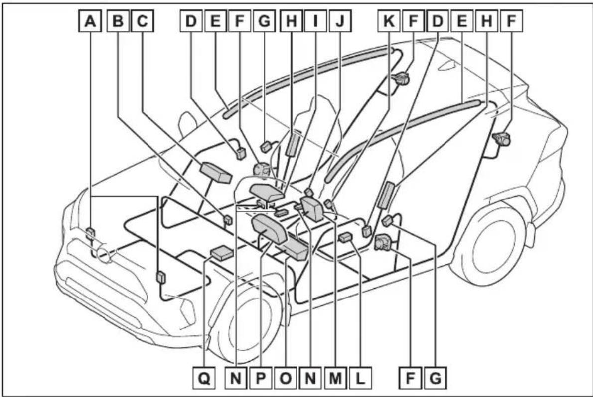
B P O N L G C D Q H I J K L I H J K L M F A EThe shape of the headlights may differ depending on the grade, etc.
A Side doors .....P.127
Locking/unlocking ......P.127
Opening/closing the side windows....P.176
Locking/unlocking by using the mechanical key .....P.128, 670
Warning messages ......P.654
B Back door....P.133
Locking/unlocking P.134
Opening from inside the cabin ^* P.137
Opening from outside....P.135, 137
Warning messages ......P.654
C Outside rear view mirrors .....P.174
Adjusting the mirror angle....P.174
Folding the mirrors .....P.174
Defogging the mirrors ^* P.526
D Windshield wipers ......P.236
Precautions against winter season....P.378
To prevent freezing (windshield wiper de-icer) ^* .....P.529
Precautions against car wash
(Rain-sensing windshield wipers) ^* P.567
Replacing the wiper insert ......P.615
Refueling method....P.241
Fuel type/fuel tank capacity .....P.685
F Tires P.590
Tire size/inflation pressure ......P.690
Winter tires/tire chain .....P.378
Checking/rotation/tire pressure warning system ^* .....P.590
Coping with flat tires....P.658
G Hood....P.579
Opening P.579
Engine oil P.686
Coping with overheat....P.677
Warning messages ......P.654
Light bulbs of the exterior lights for driving
(Replacing method: P.624, Watts: P.692)
H Headlights....P.229
I Turn signal lights P.223
J Parking lights P.229
K Daytime running lights....P.229
L Side marker lights....P.229
M Fog lights ^* P.235
N Stop lights/tail lights/turn signal lights.....P.223, 229
☐ Tail lights ......P.229
Back-up lights
Shifting the shift lever to R....P.219
P License plate lights....P.229
Q Side turn signal lights ^* P.223
*: If equipped
Instrument panel
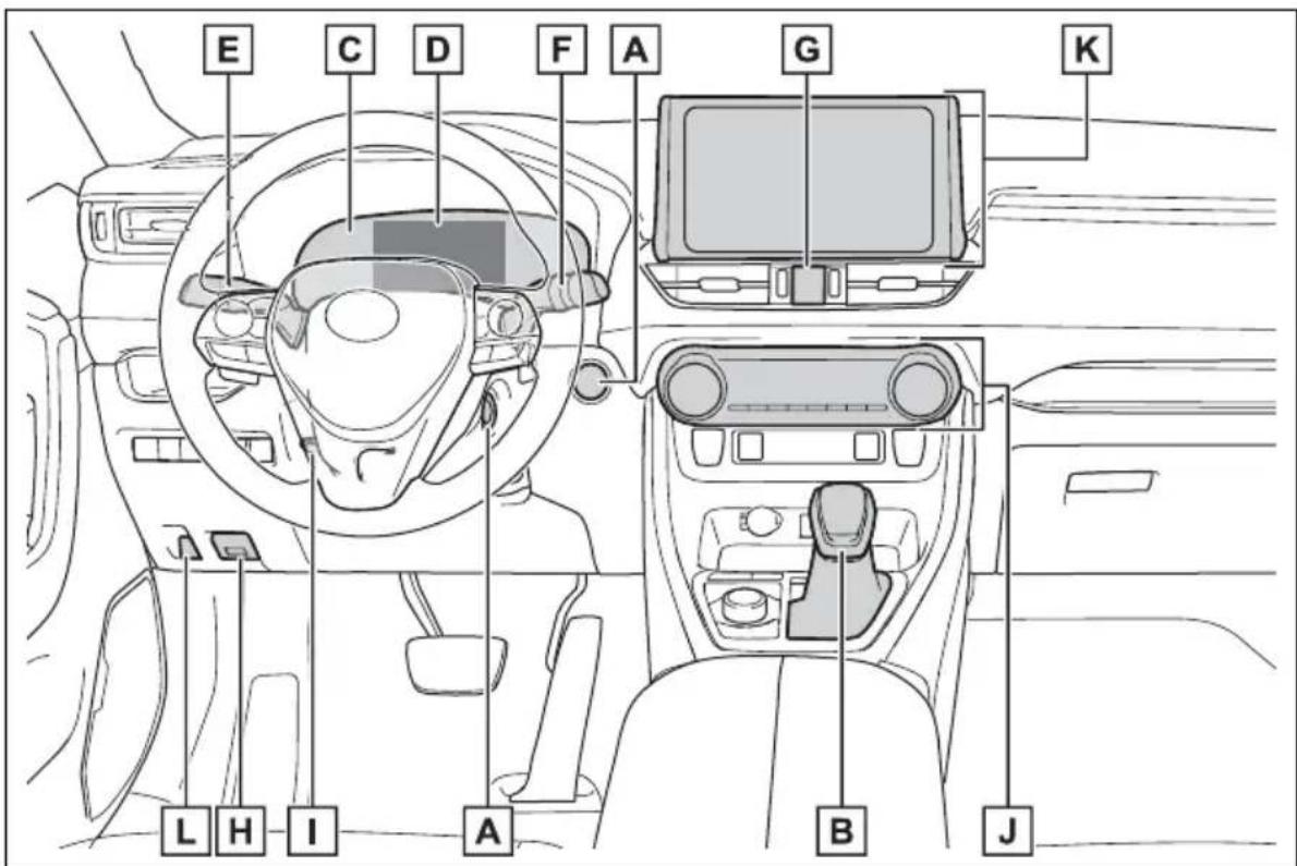
text_image
E C D F A G K L H I A B JA Power switch ......P.210, 212
Starting the hybrid system/changing the modes ..P.210, 212, 216
Emergency stop of the hybrid system.....P.635
When the hybrid system will not start ......P.667
Warning messages ^*1 P.654
B Shift lever....P.219
Changing the shift position....P.220
Precautions against towing .....P.637
When the shift lever does not move....P.221
C Meters P.94, 98
Reading the meters/adjusting the instrument panel light P.94, 96, 98, 102
Warning lights/indicator lights P.88
When the warning lights come on....P.642
D Multi-information display .....P.103
Display....P.103
Energy monitor....P.113
When the warning messages are displayed....P.654
E Turn signal lever P.223
Headlight switch P.229
Headlights/parking lights/tail lights/ license plate lights/daytime running lights....P.229
Fog lights ^*1 P.235
F Windshield wiper and washer switch .....P.236
Rear window wiper and washer switch .....P.239
Usage.....P.236, 239
Adding washer fluid....P.587
Warning messages ......P.654
G Emergency flasher switch....P.634
H Hood lock release lever....P.579
I Tilt and telescopic steering lock release lever....P.162
Adjustment ......P.162
J Air conditioning system....P.524
Usage.....P.524
Rear window defogger P.526
K Audio ^*1 P.387
Audio Plus ^*1,2
Premium Audio ^*1,2
L Fuel filler door opener switch....P.242
*1:If equipped
*2: Refer to "NAVIGATION AND MULTIMEDIA SYSTEM OWNER'S MANUAL".
Switches
text_image
A B E D C F G H I J K LA Driving position memory switches ^ .....P.156
B Window lock switch P.178
C Power window switches....P.176
D Door lock switches P.131
E Outside rear view mirror switches....P.174
F "ODO TRIP" switch P.96, 101
G Instrument panel light control dial....P.96, 102
H Automatic High Beam switch P.232
Windshield wiper de-icer switch ^ P.529
J Camera switch ^ P.336
K Heated steering wheel switch*....P.531
L Power back door switch ^ P.137
*: If equipped
text_image
A B C D G F E DA Meter control switches....P.104
B Vehicle-to-vehicle distance switch....P.277
Cruise control switches
Dynamic radar cruise control with full-speed range .....P.271
D Audio remote control switches* ......P.454
E LTA (Lane Tracing Assist) switch ......P.258
F Phone switch ^ ......P.482
G Talk switch ^ ......P.470
*: Vehicles with Audio Plus or Premium Audio, refer to "NAVIGATION AND MULTIMEDIA SYSTEM OWNER'S MANUAL".
text_image
A OFF B HI LO C D E F HOLD TRAIL ECO SPORT PUSH NORMAL EV MODE H GA VSC OFF switch ......P.370
B Front seat heater switches*....P.531
C Front seat heater/seat ventilator switches*....P.532
D Parking brake switch .....P.224
Applying/releasing....P.224
Precautions against winter season .....P.379
Warning buzzer/message ......P.648, 654
E Brake hold switch P.227
F Trail Mode switch P.367
G Driving mode select switch....P.366
H EV drive mode switch P.217
*: If equipped
Interior
text_image
E J K E F J H A D C G I BA SRS airbags....P.35
B Floor mats....P.28
C Front seats....P.153
D Rear seats....P.154
E Head restraints....P.159
F Seat belts....P.31
G Console box P.538
H Inside lock buttons....P.131
I Cup holders .....P.538
J Assist grips P.556
K Rear seat heater switches ^* P.531
*: If equipped
Ceiling
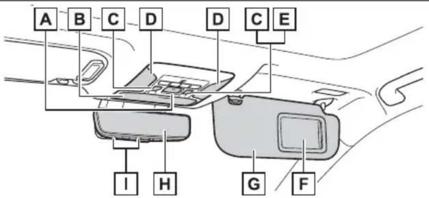
text_image
A B C D D C E I H G FA “SOS” button ^1 .....P.67
B Auxiliary box....P.539
C Moon roof switches ^1 ......P.179
D Interior lights ^*2 P.534
Personal lights P.535
E Electronic sunshade switch ^1 .....P.182
F Vanity mirrors....P.546
G Sun visors....P.546
H Inside rear view mirror ^1 ......P.163
Digital Rear-view Mirror ^*1 P.165
I Garage door opener switches ^*1 P.557
*1:If equipped
*2: The illustration shows the front, but they are also equipped in the rear.
1
1-1. For safe use
Before driving....28
For safe driving .....29
Seat belts....31
SRS airbags......35
Front passenger occupant classification system ....45
Exhaust gas precautions 50
1-2. Child safety
Riding with children.....51
Child restraint systems...52
1-3. Emergency assistance
Safety Connect ......67
1-4. Hybrid system
Hybrid system features ..72
Hybrid system precautions 76
1-5. Theft deterrent system
Immobilizer system .....81
Alarm....84
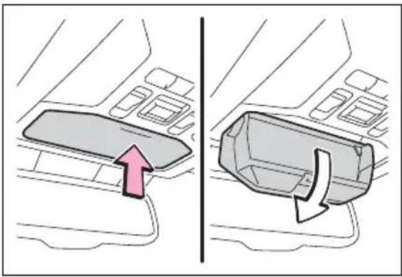
Before driving
Observe the following before starting off in the vehicle to ensure safety of driving.
Installing floor mats
Use only floor mats designed specifically for vehicles of the same model and model year as your vehicle. Fix them securely in place onto the carpet.
1 Insert the retaining hooks (clips) into the floor mat eye-lets.
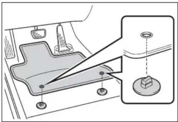
text_image
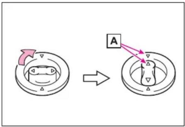
Diagram showing a car interior with labeled parts and a magnified inset highlighting a component with a washer.2 Turn the upper knob of each retaining hook (clip) to secure the floor mats in place.
flowchart
graph TD
    A["Circle Component"] --> B["Ring Structure"]
    style A fill:#f9f,stroke:#333
    style B fill:#bbf,stroke:#333
    note1["Arrow: Upward arrow"] --> A
    note2["A"] --> B
Always align the △marks . □
The shape of the retaining hooks (clips) may differ from that shown in the illustration.

WARNING
Observe the following precautions.
Failure to do so may cause the driver's floor mat to slip, possibly interfering with the pedals while driving. An unexpectedly high speed may result or it may become difficult to stop the vehicle. This could lead to an accident, resulting in death or serious injury.
- When installing the driver's floor mat
- Do not use floor mats designed for other models or different model year vehicles, even if they are Toyota Genuine floor mats.
- Only use floor mats designed for the driver's seat.
● Always install the floor mat securely using the retaining hooks (clips) provided. - Do not use two or more floor mats on top of each other.
- Do not place the floor mat bottom-side up or upside-down.

WARNING
Before driving
- Check that the floor mat is securely fixed in the correct place with all the provided retaining hooks (clips). Be especially careful to perform this check after cleaning the floor.
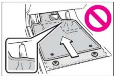
text_image
Diagram showing a vehicle interior with a directional arrow and a no-smoking symbol, indicating a restriction or prohibition.With the hybrid system stopped and the shift lever in P, fully depress each pedal to the floor to make sure it does not interfere with the floor mat.
For safe driving
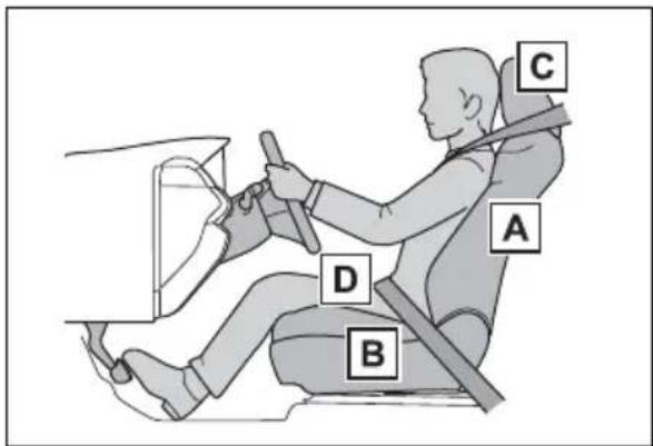
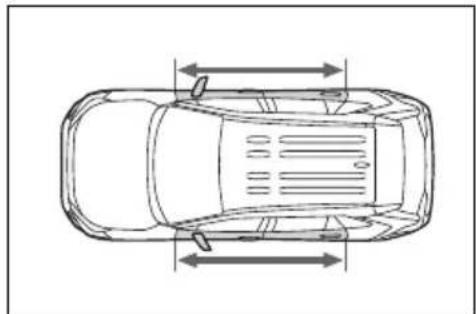
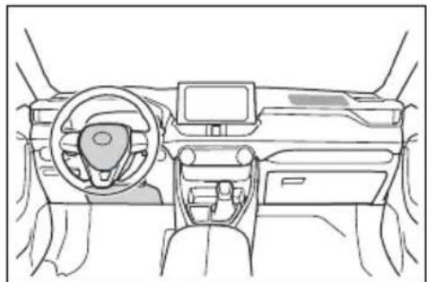
For safe driving, adjust the seat and mirror to an appropriate position before driving.
Correct driving posture
text_image
C A D BA Adjust the angle of the seat-back so that you are sitting straight up and so that you do not have to lean forward to steer. (→P.153)
B Adjust the seat so that you can depress the pedals fully and so that your arms bend slightly at the elbow when gripping the steering wheel. (→P.153)
C Lock the head restraint in place with the center of the head restraint closest to the top of your ears. (→P.159)
D Wear the seat belt correctly.
(→P.32)

WARNING
Observe the following precautions.
Failure to do so may result in death or serious injury.
- Do not adjust the position of the driver's seat while driving. Doing so could cause the driver to lose control of the vehicle.
- Do not place a cushion between the driver or passenger and the seatback. A cushion may prevent correct posture from being achieved, and reduce the effectiveness of the seat belt and head restraint.
- Do not place anything under the front seats.
Objects placed under the front seats may become jammed in the seat tracks and stop the seat from locking in place. This may lead to an accident and the adjustment mechanism may also be damaged.
● Always observe the legal speed limit when driving on public roads. - When driving over long distances, take regular breaks before you start to feel tired. Also, if you feel tired or sleepy while driving, do not force yourself to continue driving and take a break immediately.
Correct use of the seat belts
Make sure that all occupants are wearing their seat belts before driving the vehicle. ( P.32)
Use a child restraint system appropriate for the child until the child becomes large enough to
properly wear the vehicle's seat belt. (→P.52)
Adjusting the mirrors
Make sure that you can see backward clearly by adjusting the inside rear view mirror (if equipped), Digital Rear-view Mirror (if equipped) and outside rear view mirrors properly. (→P.163, 165, 174)
Seat belts
Make sure that all occupants are wearing their seat belts before driving the vehicle.

WARNING
Observe the following precautions to reduce the risk of injury in the event of sudden braking, sudden swerving or an accident. Failure to do so may cause death or serious injury.
■Wearing a seat belt
●Ensure that all passengers wear a seat belt.
●Always wear a seat belt properly.
● Each seat belt should be used by one person only. Do not use a seat belt for more than one person at once, including children.
Toyota recommends that children be seated in the rear seat and always use a seat belt and/or an appropriate child restraint system.
●To achieve a proper seating position, do not recline the seat more than necessary. The seat belt is most effective when the occupants are sitting up straight and well back in the seats.
- Do not wear the shoulder belt under your arm.
●Always wear your seat belt low and snug across your hips.
■ Pregnant women
Obtain medical advice and wear the seat belt in the proper way. (→P.32)
Women who are pregnant should position the lap belt as low as possible over the hips in the same manner as other occupants, extending the shoulder belt completely over the shoulder and avoiding belt contact with the rounding of the abdominal area.
If the seat belt is not worn properly, not only the pregnant woman, but also the fetus could suffer death or serious injury as a result of sudden braking or a collision.
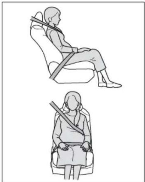
natural_image
Illustration of two different positions of a person seated in seatbelt, one using a bandage and the other using a sling (no text or symbols)■People suffering illness
Obtain medical advice and wear the seat belt in the proper way. (→P.32)
■When children are in the vehicle
$$ \rightarrow \mathrm{P.60} $$
■Seat belt damage and wear
- Do not damage the seat belts by allowing the belt, plate, or buckle to be jammed in the door.

WARNING
- Inspect the seat belt system periodically. Check for cuts, fraying, and loose parts. Do not use a damaged seat belt until it is replaced. Damaged seat belts cannot protect an occupant from death or serious injury.
- Ensure that the belt and plate are locked and the belt is not twisted. If the seat belt does not function correctly, immediately contact your Toyota dealer.
- Replace the seat assembly, including the belts, if your vehicle has been involved in a serious accident, even if there is no obvious damage.
- Do not attempt to install, remove, modify, disassemble or dispose of the seat belts. Have any necessary repairs carried out by your Toyota dealer. Inappropriate handling may lead to incorrect operation.
Correct use of the seat belts
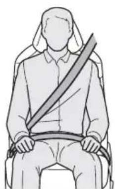
natural_image
Illustration of a person sitting in a seat with a diagonal band (no text or symbols)- Extend the shoulder belt so that it comes fully over the shoulder, but does not come into contact with the neck or slide off the shoulder.
- Position the lap belt as low as possible over the hips.
- Adjust the position of the seatback.
Sit up straight and well back in the seat. - Do not twist the seat belt.
■Child seat belt usage
The seat belts of your vehicle were principally designed for persons of adult size.
- Use a child restraint system appropriate for the child, until the child becomes large enough to properly wear the vehicle's seat belt. (→P.52)
- When the child becomes large enough to properly wear the vehicle's seat belt, follow the instructions regarding seat belt usage. ( P.31)
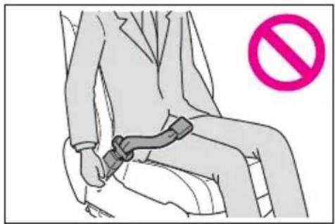
■Seat belt extender
If your seat belts cannot be fastened securely because they are not long enough, a personalized seat belt extender is available from your Toyota dealer free of charge.
natural_image
Line drawing of a car seatbelt buckle being adjusted for a knot (no text or symbols)
WARNING
■ Using a seat belt extender
Observe the following precautions to reduce the risk of injury in the event of sudden braking, sudden swerving or an accident. Failure to do so may cause death or serious injury.

WARNING
- Do not wear the seat belt extender if you can fasten the seat belt without the extender.
- Do not use the seat belt extender when installing a child restraint system because the belt will not securely hold the child restraint system, increasing the risk of death or serious injury in the event of an accident.
●The personalized extender may not be safe on another vehicle, when used by another person, or at a different seating position other than the one originally intended.

NOTICE
■When using a seat belt extender
When releasing the seat belt, press on the buckle release button on the extender, not on the seat belt. This helps prevent damage to the vehicle interior and the extender itself.
Fastening and releasing the seat belt
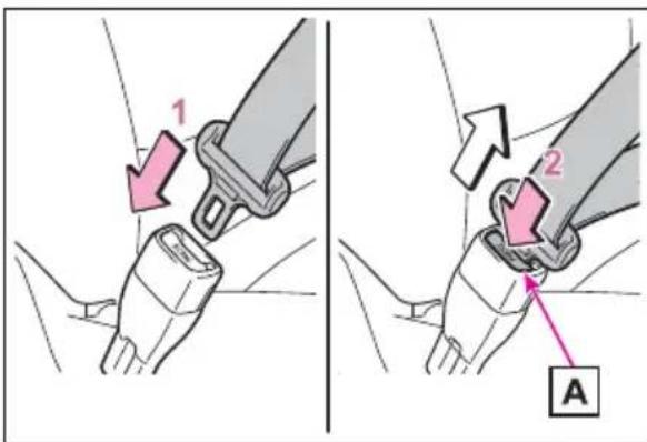
text_image
1 2 A1 To fasten the seat belt, push the plate into the buckle until
a click sound is heard.
2 To release the seat belt, press the release button A
Emergency locking retractor (ELR)
The retractor will lock the belt during a sudden stop or on impact. It may also lock if you lean forward too quickly. A slow, easy motion will allow the belt to extend so that you can move around fully.
■Automatic locking retractor (ALR)
When a passenger's shoulder belt is completely extended and then retracted even slightly, the belt is locked in that position and cannot be extended. This feature is used to hold a child restraint system (CRS) firmly. To free the belt again, fully retract the belt and then pull the belt out once more.
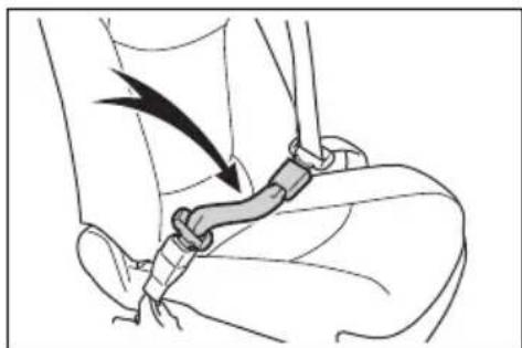
Adjusting the seat belt shoulder anchor height (front seats)
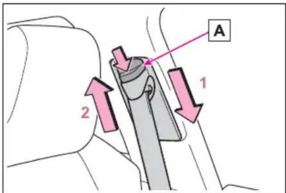
text_image
A 1 21 Push the seat belt shoulder anchor down while pressing the release button A
2 Push the seat belt shoulder anchor up while pressing the release button A
Move the height adjuster up and down as needed until you hear a click.

WARNING
■Adjustable shoulder anchor
Always make sure the shoulder belt is positioned across the center of your shoulder. The belt should be kept away from your neck, but not falling off your shoulder. Failure to do so could reduce the amount of protection in an accident and cause death or serious injuries in the event of a sudden stop, sudden swerve or accident.
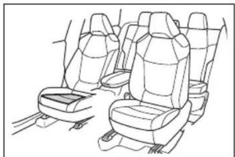
Seat belt pretensioners (front and outboard rear seats)
The pretensioners help the seat belts to quickly restrain the occupants by retracting the seat belts when the vehicle is subjected to certain types of severe frontal collision or a vehicle roll-over.
The pretensioners do not activate in the event of a minor frontal impact, a minor side impact or a rear impact.
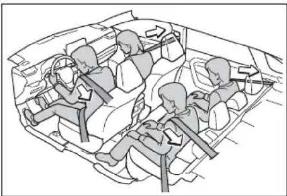
natural_image
Diagram of a car interior showing multiple people seated in the backseat with directional arrows indicating movement or force (no text or symbols present)■Replacing the belt after the pre-tensioner has been activated
If the vehicle is involved in multiple collisions, the pretensioner will activate for the first collision, but will not activate for the second or subsequent collisions.

WARNING
■Seat belt pretensioners
Observe the following precautions to reduce the risk of injury in the event of sudden braking, sudden swerving or an accident. Failure to do so may cause death or serious injury.
- Do not place anything, such as a cushion, on the front passenger's seat. Doing so will disperse the passenger's weight, which prevents the sensor from detecting the passenger's weight properly. As a result, the seat belt pretensioner for the front passenger's seat may not activate in the event of a collision.
- If the pretensioner has activated, the SRS warning light will come on. In that case, the seat belt cannot be used again and must be replaced at your Toyota dealer.
SRS airbags
The SRS airbags inflate when the vehicle is subjected to certain types of severe impacts that may cause significant injury to the occupants. They work together with the seat belts to help reduce the risk of death or serious injury.
SRS airbag system
■ Location of the SRS airbags
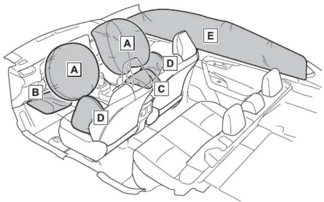
text_image
A B C D D A B C D E▶ SRS front airbags
A SRS driver airbag/front passenger airbag
Can help protect the head and chest of the driver and front passenger from impact with interior components
B SRS knee airbag
Can help provide driver protection
c SRS seat cushion airbag
Can help restrain the front passenger
▶ SRS side and curtain shield airbags
D SRS side airbags
Can help protect the torso of the front seat occupants
E SRS curtain shield airbags
- Can help protect primarily the head of occupants in the outer seats
- Can help prevent the occupants from being thrown from the vehicle in the event of vehicle rollover
■SRS airbag system components
text_image
A B C D E F G H I J K F D E H F Q N P O N M L F GA Front impact sensors
B "AIR BAG ON" and "AIR BAG OFF" indicator lights
C Front passenger airbag
D Side impact sensors (front door)
E Curtain shield airbags
F Seat belt pretensioners and force limiters
G Side impact sensors (front)
H Side airbags
I Seat cushion airbag
J Front passenger's seat belt buckle switch
K Driver's seat belt buckle switch
L Driver's seat position sensor
M Driver airbag
N Front passenger occupant classification system (ECU and sensors)
Knee airbag
P SRS warning light
Q Airbag sensor assembly
Your vehicle is equipped with ADVANCED AIRBAGS designed based on the US motor vehicle safety standards (FMVSS208). The airbag sensor assembly (ECU) controls airbag deployment based on information obtained from the sensors etc. shown in the system components diagram above. This information includes crash severity and occupant information. As the airbags deploy, a chemical reaction in the inflators quickly fills the airbags with non-toxic gas to help restrain the motion of the occupants.
■If the SRS airbags deploy (inflate)
- Slight abrasions, burns, bruising etc., may be sustained from SRS airbags, due to the extremely high speed deployment (inflation) by hot gases.
●A loud noise and white powder will be emitted.
● Parts of the airbag module (steering wheel hub, airbag cover and inflator) as well as the front seats, parts of the front and rear pillars, and roof side rails, may be hot for several minutes. The airbag itself may also be hot.
●The windshield may crack.
●The hybrid system will be stopped and fuel supply to the engine will be stopped. (→P.80)
●The brakes and stop lights will be controlled automatically. (→P.370)
●The interior lights will turn on automatically. (→P.535)
●The emergency flashers will turn on automatically. (→P.634)
●For Safety Connect subscribers, if any of the following situations
occur, the system is designed to send an emergency call to the response center, notifying them of the vehicle's location (without needing to push the "SOS" button) and an agent will attempt to speak with the occupants to ascertain the level of emergency and assistance required. If the occupants are unable to communicate, the agent automatically treats the call as an emergency and helps to dispatch the necessary emergency services. (→P.67)
- An SRS airbag is deployed.
- A seat belt pretensioner is activated.
- The vehicle is involved in a severe rear-end collision.
■ SRS airbag deployment conditions (SRS front airbags)
●The SRS front airbags will deploy in the event of an impact that exceeds the set threshold level (the level of force corresponding to an approximately 12 - 18 mph [20 - 30 km/h] frontal collision with a fixed wall that does not move or deform).
However, this threshold velocity will be considerably higher in the following situations:
- If the vehicle strikes an object, such as a parked vehicle or sign pole, which can move or deform on impact
- If the vehicle is involved in an underride collision, such as a collision in which the front of the vehicle underrides, or goes under, the bed of a truck
●Depending on the type of collision, it is possible that only the seat belt pretensioners will activate.
●The SRS front airbags for the front passenger will not activate if there is no passenger sitting in the front passenger seat. However, the SRS front airbags for the front passenger may deploy if luggage is put in the seat, even if the seat is unoccupied.
●The SRS seat cushion airbag on the front passenger seat will not operate if the occupant is not wearing a seat belt.
■ SRS airbag deployment conditions (SRS side and curtain shield airbags)
●The SRS side and curtain shield airbags will deploy in the event of an impact that exceeds the set threshold level (the level of force corresponding to the impact force produced by an approximately 3300 lb. [1500 kg] vehicle colliding with the vehicle cabin from a direction perpendicular to the vehicle orientation at an approximate speed of 12 - 18 mph [20 - 30 km/h]).
● Both SRS curtain shield airbags will deploy in the event of a side collision on either side.
● Both SRS curtain shield airbags will deploy in the event of vehicle rollover.
●Both SRS curtain shield airbags may also deploy in the event of a severe frontal collision.
■Conditions under which the SRS airbags may deploy (inflate), other than a collision
The SRS front airbags and SRS curtain shield airbags may also deploy if a serious impact occurs to the underside of your vehicle. Some examples are shown in the illustration.
●Hitting a curb, edge of pavement or hard surface
●Falling into or jumping over a deep hole
●Landing hard or falling
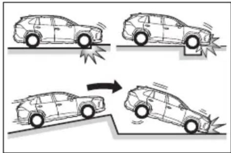
text_image
Diagram illustrating vehicle collision and impact on a car, showing four scenarios with collision and impact indicators.The SRS curtain shield airbags may also deploy under the situations shown in the illustration.
●The angle of vehicle tip-up is marginal.
●The vehicle skids and hits a curb stone.
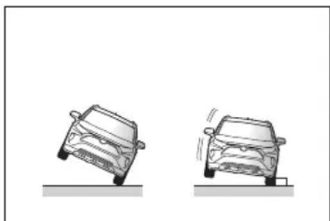
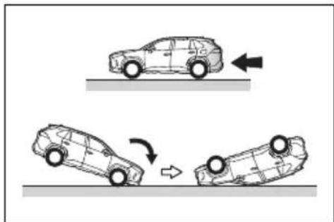
natural_image
Two cartoon-style cars on a flat surface, one rolling down the ground and the other standing upright (no text or symbols)■Types of collisions that may not deploy the SRS airbags (SRS front airbags)
The SRS front airbags do not generally inflate if the vehicle is involved in a side or rear collision, if it rolls over, or if it is involved in a low-speed frontal collision. But, whenever a collision of any type causes sufficient forward deceleration of the vehicle, deployment of the SRS
front airbags may occur.
●Collision from the side
●Collision from the rear
● Vehicle rollover
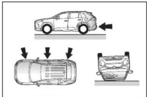
text_image
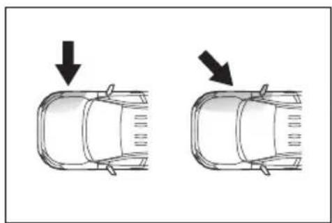
Diagram illustrating vehicle collision scenarios with arrows indicating movement and damage points■Types of collisions that may not deploy the SRS airbags (SRS side and curtain shield airbags)
The SRS side and curtain shield airbags may not activate if the vehicle is subjected to a collision from the side at certain angles, or a collision to the side of the vehicle body other than the passenger compartment.
- Collision from the side to the vehicle body other than the passenger compartment
●Collision from the side at an angle
natural_image
Diagram showing two car side profiles with arrows indicating downward motion (no text or symbols)The SRS side airbags do not generally inflate if the vehicle is involved in a frontal or rear collision, if it rolls over, or if it is involved in a low-speed side collision.
●Collision from the front
- Collision from the rear
●Vehicle rollover
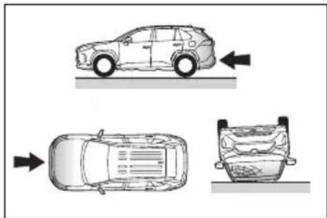
natural_image
Diagram showing three views of a car with directional arrows indicating top, front, and side views (no text or symbols)The SRS curtain shield airbags do not generally inflate if the vehicle is involved in a rear collision, if it pitches end over end, or if it is involved in a low-speed side or low-speed frontal collision.
- Collision from the rear
●Pitching end over end
natural_image
Diagram showing three car trajectories on a surface, illustrating dynamic movement (no text or symbols)■When to contact your Toyota dealer
In the following cases, the vehicle will require inspection and/or repair. Contact your Toyota dealer as soon as possible.
● Any of the SRS airbags have been inflated.
●The front of the vehicle is damaged or deformed, or was involved in an accident that was not severe enough to cause the SRS front airbags to inflate.
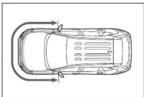
natural_image
Top-down line drawing of a car showing side and top views with curved arrows indicating flow or movement (no text or symbols)●A portion of a door or its surrounding area is damaged, deformed or has had a hole made in it, or the
vehicle was involved in an accident that was not severe enough to cause the SRS side and curtain shield airbags to inflate.
natural_image
Top-down line drawing of a car showing front and rear views with directional arrows (no text or symbols)●The pad section of the steering wheel, dashboard near the front passenger airbag or lower portion of the instrument panel is scratched, cracked, or otherwise damaged.
natural_image
Line drawing of a car interior showing steering wheel, dashboard, and steering wheel (no text or symbols)- The front passenger's seat cushion surface is scratched, cracked, or otherwise damaged.
natural_image
Line drawing of a car interior showing multiple seats and seat compartments (no text or symbols)●The surface of the seats with the SRS side airbag is scratched, cracked, or otherwise damaged.
natural_image
Line drawing of a car interior showing steering wheel, dashboard, and seat (no text or symbols)● The portion of the front pillars, rear pillars or roof side rail garnishes (padding) containing the SRS curtain shield airbags inside is scratched, cracked, or otherwise damaged.
natural_image
Line drawing of a car exterior view showing front and rear panels (no text or symbols)
WARNING
■SRS airbag precautions
Observe the following precautions regarding the SRS airbags. Failure to do so may cause death or serious injury.
●The driver and all passengers in the vehicle must wear their seat belts properly. The SRS airbags are supplemental devices to be used with the seat belts.
●The SRS driver airbag deploys with considerable force, and can cause death or serious injury especially if the driver is very close to the airbag. The National Highway Traffic Safety Administration (NHTSA) advises:
Since the risk zone for the driver's airbag is the first 2 - 3 in. (50 - 75 mm) of inflation, placing yourself 10 in. (250 mm) from your driver airbag provides you with a clear margin of safety. This distance is measured from the center of the steering wheel to your breast-bone. If you sit less than 10 in. (250 mm) away now, you can change your driving position in several ways:

WARNING
- Move your seat to the rear as far as you can while still reaching the pedals comfortably.
- Slightly recline the back of the seat.
Although vehicle designs vary, many drivers can achieve the 10 in. (250 mm) distance, even with the driver seat all the way forward, simply by reclining the back of the seat somewhat. If reclining the back of your seat makes it hard to see the road, raise yourself by using a firm, non-slippery cushion, or raise the seat if your vehicle has that feature.
- If your steering wheel is adjustable, tilt it downward. This points the airbag toward your chest instead of your head and neck.
The seat should be adjusted as recommended by NHTSA above, while still maintaining control of the foot pedals, steering wheel, and your view of the instrument panel controls.
- If the seat belt extender has been connected to the front seat belt buckles but the seat belt extender has not also been fastened to the latch plate of the seat belt, the SRS front airbags will judge that the driver and front passenger are wearing the seat belt even though the seat belt has not been connected. In this case, the SRS front airbags may not activate correctly in a collision, resulting in death or serious injury in the event of a collision. Be sure to wear the seat belt with the seat belt extender.
text_image
Illustration of a person's seatbelt with a no-smoking symbol nearby●The SRS front passenger airbag also deploys with considerable force, and can cause death or serious injury especially if the front passenger is very close to the airbag. The front passenger seat should be as far from the airbag as possible with the seat-back adjusted, so the front passenger sits upright.
- Improperly seated and/or restrained infants and children can be killed or seriously injured by a deploying airbag. An infant or child who is too small to use a seat belt should be properly secured using a child restraint system. Toyota strongly recommends that all infants and children be placed in the rear seats of the vehicle and properly restrained. The rear seats are safer for infants and children than the front passenger seat. (→P.52)

WARNING
- Do not sit on the edge of the seat or lean against the dashboard.
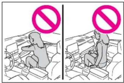
text_image
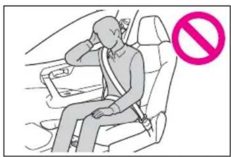
Diagram showing two scenarios of a person seated in car seats, each with a 'no' symbol indicating no prohibition.- Do not allow a child to stand in front of the SRS front passenger airbag unit or sit on the knees of a front passenger.
text_image
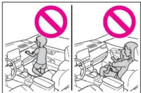
Diagram showing two scenarios of a child inside a vehicle, one with a no-smoking symbol and the other with a no-smoking symbol.- Do not allow the front seat occupants to hold items on their knees.
- Do not lean against the door, the roof side rail or the front, side and rear pillars.
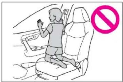
natural_image
Illustration of a person sitting in a car seat with a pink prohibition symbol (no text or labels)- Do not allow anyone to kneel on the passenger seat toward the door or put their head or hands outside the vehicle.
text_image
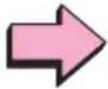
Illustration of a child sitting in a car seat with a 'no' symbol indicating no restriction.- Do not attach anything to or lean anything against areas such as the dashboard, steering wheel pad and lower portion of the instrument panel. These items can become projectiles when the SRS driver, front passenger and knee air bags deploy.
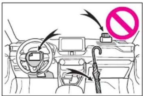
text_image
Diagram of a car interior showing steering wheel, dashboard, and umbrella with no stop sign indicating no restriction- Do not attach anything to areas such as a door, windshield, side windows, front or rear pillar, roof side rail and assist grip.
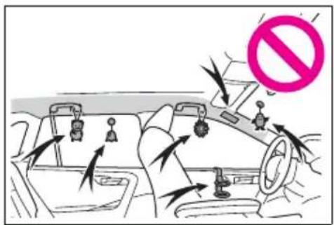
text_image
Diagram showing car safety instructions with a no-smoking symbol and directional arrows indicating movement
WARNING
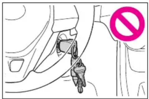
- Vehicles without smart key system: Do not attach any heavy, sharp or hard objects such as keys and accessories to the key. The objects may restrict the SRS knee airbag inflation or be thrust into the driver's seat area by the force of the deploying airbag, thus causing a danger.
text_image
Diagram showing a car's seatbelt with a no-smoking symbol, indicating no vehicle use or absence.- Do not hang coat hangers or other hard objects on the coat hooks. All of these items could become projectiles and may cause death or serious injury, should the SRS curtain shield airbags deploy.
- If a vinyl cover is put on the area where the SRS knee airbag will deploy, be sure to remove it.
-
Do not use seat accessories which cover the parts where the SRS side airbags and SRS seat cushion airbag inflate as they may interfere with inflation of the SRS airbags. Such accessories may prevent the SRS side airbags and SRS seat cushion airbag from activating correctly, disable the system or cause the SRS side airbags and SRS seat cushion airbag to inflate accidentally, resulting in death or serious injury.
-
Do not strike or apply significant levels of force to the area of the SRS airbag components or the front doors. Doing so can cause the SRS airbags to malfunction.
- Do not touch any of the component parts immediately after the SRS airbags have deployed (inflated) as they may be hot.
- If breathing becomes difficult after the SRS airbags have deployed, open a door or side window to allow fresh air in, or leave the vehicle if it is safe to do so. Wash off any residue as soon as possible to prevent skin irritation.
- If the areas where the SRS airbags are stored, such as the steering wheel pad and front and rear pillar garnishes, are damaged or cracked, have them replaced by your Toyota dealer.
- Do not place anything, such as a cushion, on the front passenger's seat. Doing so will disperse the passenger's weight, which prevents the sensor from detecting the passenger's weight properly. As a result, the SRS front airbags for the front passenger may not deploy in the event of a collision.

WARNING
■Modification and disposal of SRS airbag system components
Do not dispose of your vehicle or perform any of the following modifications without consulting your Toyota dealer. The SRS airbags may malfunction or deploy (inflate) accidentally, causing death or serious injury.
● Installation, removal, disassembly and repair of the SRS air-bags
● Repairs, modifications, removal or replacement of the steering wheel, instrument panel, dashboard, seats or seat upholstery, front, side and rear pillars, roof side rails, front door panels, front door trims or front door speakers
● Modifications to the front door panel (such as making a hole in it)
● Repairs or modifications of the front fender, front bumper, or side of the occupant compartment
● Installation of a grille guard (bull bars, kangaroo bar, etc.), snow plows, winches or roof luggage carrier
- Modifications to the vehicle's suspension system
● Installation of electronic devices such as mobile two-way radios and CD players
● Modifications to your vehicle for a person with a physical disability
Front passenger occupant classification system
Your vehicle is equipped with a front passenger occupant classification system. This system detects the conditions of the front passenger seat and activates or deactivates the front passenger airbag and seat cushion airbag in the front passenger side.
System components
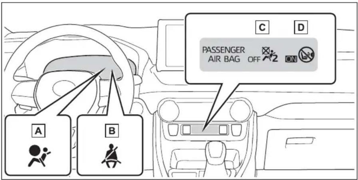
text_image
A B C D PASSENGER AIR BAG OFF ONA SRS warning light
B Driver's and front passenger's seat belt reminder light
C "AIR BAG OFF" indicator light
D "AIR BAG ON" indicator light

WARNING
■Front passenger occupant classification system precautions
Observe the following precautions regarding the front passenger occupant classification system. Failure to do so may cause death or serious injury.
●Wear the seat belt properly.
Make sure the front passenger's seat belt plate has not been left inserted into the buckle before someone sits in the front passenger seat.

WARNING
Make sure the “AIR BAG OFF” indicator light is not illuminated when using the seat belt extender for the front passenger seat. If the “AIR BAG OFF” indicator light is illuminated, disconnect the extender tongue from the seat belt buckle, and reconnect the seat belt. Reconnect the seat belt extender after making sure the “AIR BAG ON” indicator light is illuminated. If you use the seat belt extender while the “AIR BAG OFF” indicator light is illuminated, the SRS airbags for the front passenger will not activate, which could cause death or serious injury in the event of a collision.
- Do not apply a heavy load to the front passenger seat or equipment (e.g. seatback pocket).
- Do not put weight on the front passenger seat by putting your hands or feet on the front passenger seat seatback from the rear passenger seat.
- Do not let a rear passenger lift the front passenger seat with their feet or press on the seat-back with their legs.
-
Do not put objects under the front passenger seat.
-
Do not recline the front passenger seatback so far that it touches a rear seat. This may cause the “AIR BAG OFF” indicator light to be illuminated, which indicates that the SRS airbags for the front passenger will not activate in the event of a severe accident. If the seatback touches the rear seat, return the seatback to a position where it does not touch the rear seat. Keep the front passenger seatback as upright as possible when the vehicle is moving. Reclining the seatback excessively may lessen the effectiveness of the seat belt system.
- If an adult sits in the front passenger seat, the “AIR BAG ON” indicator light is illuminated. If the “AIR BAG OFF” indicator is illuminated, ask the passenger to sit up straight, well back in the seat, feet on the floor, and with the seat belt worn correctly. If the “AIR BAG OFF” indicator still remains illuminated, either ask the passenger to move to the rear seat, or if that is not possible, move the front passenger seat fully rearward.
- When it is unavoidable to install a forward-facing child restraint system on the front passenger seat, install the child restraint system on the front passenger seat in the proper order. (→P.55)
- Do not modify or remove the front seats.
- Do not kick the front passenger seat or subject it to severe impact. Otherwise, the SRS warning light may come on to indicate a malfunction of the front passenger occupant classification system. In this case, contact your Toyota dealer immediately.

WARNING
● Child restraint systems installed on the rear seat should not contact the front seatbacks.
- Do not use a seat accessory, such as a cushion and seat cover, that covers the seat cushion surface.
- Do not modify or replace the upholstery of the front seat.
- Adjust the front passenger seat so that the head restraint does not touch the ceiling. If the head restraint is left in contact with the ceiling, the system may not detect the front passenger properly, leading to improper operation of the airbags.
Condition and operation in the front passenger occupant classification system
■Adult *1
| Indicators/warning lights | “AIR BAG ON” and “AIR BAG OFF” indicator lights | “AIR BAG ON” |
| SRS warning light Off | ||
| Driver’s and front passenger’s seat belt reminder light | Off^*2 or flashing^*3 | |
| Devices | Front passenger airbag Activated | |
| Front passenger seat cushion airbag | Activated^*2 or deactivated^*3 | |
Child *4
| Indicators/warning lights | “AIR BAG ON” and “AIR BAG OFF” indicator lights | “AIR BAG OFF” or “AIR BAG ON”*4 |
| SRS warning light Off | ||
| Driver’s and front passenger’s seat belt reminder light | Off*2 or flashing*3 | |
| Devices | Front passenger airbag | Deactivated or activated*4 |
| Front passenger seat cushion airbag | Deactivated or activated*2, 4 |
■Child restraint system with infant *5
| Indicators/warning lights | “AIR BAG ON” and “AIR BAG OFF” indicator lights | “AIR BAG OFF” *6 |
| SRS warning light Off | ||
| Driver’s and front passenger’s seat belt reminder light | Off*2 or flashing*3 | |
| Devices | Front passenger airbag | Deactivated |
| Front passenger seat cushion airbag |
Unoccupied
| Indicators/warning lights | “AIR BAG ON” and “AIR BAG OFF” indicator lights | “AIR BAG OFF” |
| SRS warning light | Off | |
| Driver’s and front passenger’s seat belt reminder light | ||
| Devices | Front passenger airbag | Deactivated |
| Front passenger seat cushion airbag |
■There is a malfunction in the system
| Indicators/warning lights | “AIR BAG ON” and “AIR BAG OFF” indicator lights | “AIR BAG OFF” |
| SRS warning light | On | |
| Driver’s and front passenger’s seat belt reminder light | ||
| Devices | Front passenger airbag | Deactivated |
| Front passenger seat cushion airbag |
*1: The system judges a person of adult size as an adult. When a smaller adult sits in the front passenger seat, the system may not recognize him/her as an adult depending on his/her physique and posture.
*2: In the event the front passenger is wearing a seat belt.
^*3 :In the event the front passenger does not wear a seat belt.
*4: For some children, child in seat, child in booster seat or child in convertible seat, the system may not recognize him/her as a child. Factors which may affect this can be the physique or posture.
*5: Never install a rear-facing child restraint system on the front passenger seat. A forward-facing child restraint system should only be installed on the front passenger seat when it is unavoidable. (→P.55)
^*6 : In case the indicator light is not illuminated, consult this manual on how to install the child restraint system properly. ( P.52)
Exhaust gas precautions
Harmful substance to the human body is included in exhaust gases if inhaled.

WARNING
Exhaust gases contain harmful carbon monoxide (CO), which is colorless and odorless. Observe the following precautions. Failure to do so may cause exhaust gases to enter the vehicle and may lead to an accident caused by light-headedness, or may lead to death or a serious health hazard.
■ Important points while driving
- Keep the back door closed.
- If you smell exhaust gases in the vehicle even when the back door is closed, open the side windows and have the vehicle inspected at your Toyota dealer as soon as possible.
When parking
- If the vehicle is in a poorly ventilated area or a closed area, such as a garage, stop the hybrid system.
- Do not leave the vehicle with the hybrid system operating for a long time. If such a situation cannot be avoided, park the vehicle in an open space and ensure that exhaust fumes do not enter the vehicle interior.
- Do not leave the hybrid system operating in an area with snow build-up, or where it is snowing. If snowbanks build up around the vehicle while the hybrid system is operating, exhaust gases may collect and enter the vehicle.
Exhaust pipe
The exhaust system needs to be checked periodically. If there is a hole or crack caused by corrosion, damage to a joint or abnormal exhaust noise, be sure to have the vehicle inspected and repaired by your Toyota dealer.
Riding with children
Observe the following precautions when children are in the vehicle.
Use a child restraint system appropriate for the child, until the child becomes large enough to properly wear the vehicle's seat belt.
- It is recommended that children sit in the rear seats to avoid accidental contact with the shift lever, wiper switch, etc.
- Use the rear door child-protector lock or the window lock switch to avoid children opening the door while driving or operating the power window accidentally. (→P.132, 178)
- Do not let small children operate equipment which may catch or pinch body parts, such as the power window, hood, back door, seats, etc.

WARNING
■When children are in the vehicle
Never leave children unattended in the vehicle, and never allow children to have or use the key.
Children may be able to start the vehicle or shift the vehicle into neutral. There is also a danger that children may injure themselves by playing with the side windows, the moon roof (if equipped), the panoramic moon roof (if equipped) or other features of the vehicle. In addition, heat build-up or extremely cold temperatures inside the vehicle can be fatal to children.
Child restraint systems
Before installing a child restraint system in the vehicle, there are precautions that need to be observed, different types of child restraint systems, as well as installation methods, etc., written in this manual.
Use a child restraint system when riding with a small child that cannot properly use a seat belt. For the child's safety, install the child restraint system to a rear seat. Be sure to follow the installation method that is in the operation manual enclosed with the restraint system.
Table of contents
Points to remember: P.52
Child restraint system: P.54
When using a child restraint system: P.55
Child restraint system installation method
- Fixed with a seat belt: P.56
- Fixed with a child restraint LATCH anchor: P.61
- Using an anchor bracket (for top tether strap): P.63
Points to remember
The laws of all 50 states of the U.S.A. as well as Canada now require the use of child restraint systems.
- Prioritize and observe the warnings, as well as the laws and regulations for child restraint systems.
- Use a child restraint system until the child becomes large enough to properly wear the vehicle's seat belt.
- Choose a child restraint system that suits your vehicle and is appropriate to the age and size of the child.

WARNING
■When a child is riding
Observe the following precautions.
Failure to do so may result in death or serious injury.
For effective protection in automobile accidents and sudden stops, a child must be properly restrained, using a seat belt or child restraint system which is correctly installed. For installation details, refer to the operation manual enclosed with the child restraint system. General installation instructions are provided in this manual.

WARNING
Toyota strongly urges the use of a proper child restraint system that conforms to the weight and size of the child, installed on the rear seat. According to accident statistics, the child is safer when properly restrained in the rear seat than in the front seat.
- Holding a child in your or someone else's arms is not a substitute for a child restraint system. In an accident, the child can be crushed against the windshield or between the holder and the interior of the vehicle.
■Handling the child restraint system
If the child restraint system is not properly fixed in place, the child or other passengers may be seriously injured or even killed in the event of sudden braking, sudden swerving, or an accident.
- If the vehicle were to receive a strong impact from an accident, etc., it is possible that the child restraint system has damage that is not readily visible. In such cases, do not reuse the restraint system.
Make sure you have complied with all installation instructions provided with the child restraint system manufacturer and that the system is properly secured.
- Keep the child restraint system properly secured on the seat even if it is not in use. Do not store the child restraint system unsecured in the passenger compartment.
- If it is necessary to detach the child restraint system, remove it from the vehicle or store it securely in the luggage compartment.
Child restraint system
■Types of child restraint system installation methods
Confirm with the operation manual enclosed with the child restraint system about the installation of the child restraint system.
| Installation method Page | ||
| Seat belt attachment P. |  | |
| Child restraint LATCH anchors attachment | 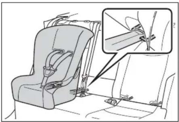 | P.61 |
| Anchor brackets (for top tether strap) attach-ment | 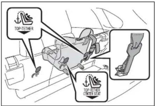 | P.63 |
When using a child restraint system
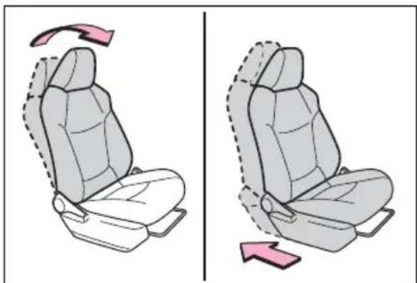
■When installing a child restraint system to a front passenger seat
For the safety of a child, install a child restraint system to a rear seat. When installing the child restraint system to a front passenger seat is unavoidable, adjust the seat as follows and install the child restraint system.
- Adjust the seatback angle to the most upright position.
- Move the front seat fully rearward.
- If the head restraint interferes with the child restraint system installation and the head restraint can be removed, remove the head restraint. Otherwise, put the head restraint in the upper most position.
natural_image
Illustration of a car seat with rotation arrows indicating clockwise motion (no text or symbols)
WARNING
■When using a child restraint system
Observe the following precautions. Failure to do so may result in death or serious injury.
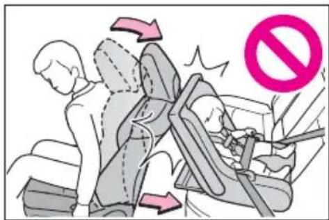
● Never install a rear-facing child restraint system on the front passenger seat even if the “AIR BAG OFF” indicator light is illuminated. In the event of an accident, the force of the rapid inflation of the front passenger airbag can cause death or serious injury to the child if the rear-facing child restraint system is installed on the front passenger seat.
● A forward-facing child restraint system may be installed on the front passenger seat only when it is unavoidable. A child restraint system that requires a top tether strap should not be used in the front passenger seat since there is no top tether strap anchor for the front passenger seat.

WARNING
A forward-facing child restraint system may be installed on the front passenger seat only when it is unavoidable. When installing a forward-facing child restraint system on the front passenger seat, adjust the seat-back angle to the most upright position, move the seat to the rearmost position, even if the "AIR BAG OFF" indicator light is illuminated. If the head restraint interferes with the child restraint system installation and the head restraint can be removed, remove the head restraint.
natural_image
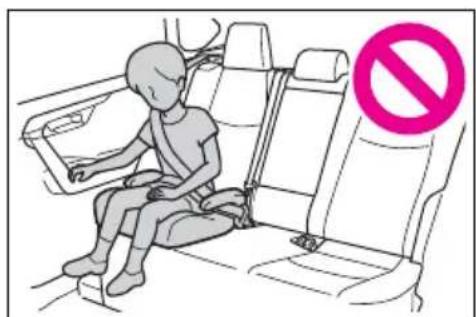
Illustration of a child seated in a car seat inside a vehicle, with an arrow indicating direction (no text or symbols)- Do not allow the child to lean his/her head or any part of his/her body against the door or the area of the seat, front or rear pillars, or roof side rails from which the SRS side airbags or SRS curtain shield airbags deploy even if the child is seated in the child restraint system. It is dangerous if the SRS side and curtain shield airbags inflate, and the impact could cause death or serious injury to the child.
natural_image
Illustration of a person sitting in a car seat with a no-smoking symbol (no text or labels present)When a booster seat is installed, always ensure that the shoulder belt is positioned across the center of the child's shoulder. The belt should be kept away from the child's neck, but not so that it could fall off the child's shoulder.
- Use a child restraint system suitable to the age and size of the child and install it to the rear seat.
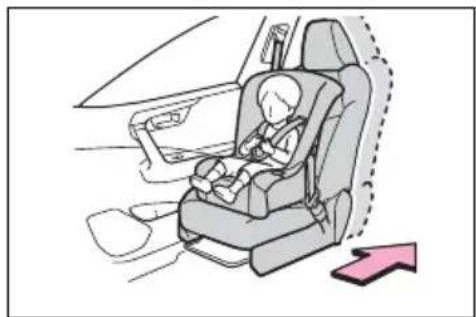
- If the driver's seat interferes with the child restraint system and prevents it from being attached correctly, attach the child restraint system to the right-hand rear seat.
text_image
Safety instruction illustration showing passenger and child car seatbelting with no stop symbol- Adjust the front passenger seat so that it does not interfere with the child restraint system.
Child restraint system fixed with a seat belt
A child restraint system for a small child or baby must itself be properly restrained on the seat with the lap portion of the lap/shoulder belt.
■Installing child restraint system using a seat belt (child restraint lock function belt)
Install the child restraint system in accordance to the operation
manual enclosed with the child restraint system.
■Rear-facing — Infant seat/convertible seat
1 Adjust the rear seat.
If there is a gap between the child restraint system and the seatback, adjust the seatback angle until good contact is achieved.
2 Place the child restraint system on the rear seat facing the rear of the vehicle.
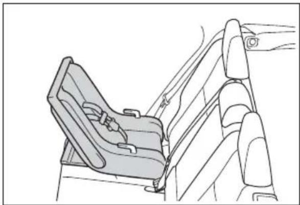
natural_image
Line drawing of a car seatbelt seat assembly (no text or symbols)3 Run the seat belt through the child restraint system and insert the plate into the buckle. Make sure that the belt is not twisted.
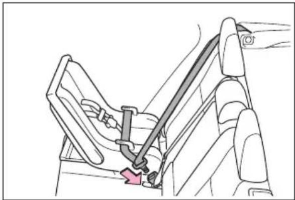
natural_image
Diagram of a car seatbelt mechanism showing a key inserted into the seat (no text or symbols present)4 Fully extend the shoulder belt and allow it to retract to put it
in lock mode. In lock mode, the belt cannot be extended.
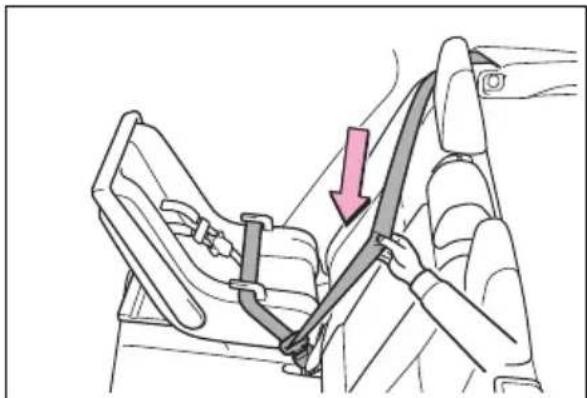
natural_image
Diagram of a car seatbelt buckle being lifted, showing a hand holding the seat (no text or symbols present)5 While pushing the child restraint system down into the rear seat, allow the shoulder belt to retract until the child restraint system is securely in place.
After the shoulder belt has retracted to a point where there is no slack in the belt, pull the belt to check that it cannot be extended.
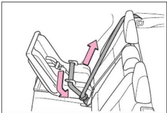
natural_image
Diagram of a car seatbelt mechanism showing two directional arrows indicating movement (no text or symbols present)6 After installing the child restraint system, rock it back and forth to ensure that it is installed securely. (→P.60)
■Forward-facing — Convert- ible seat
1 Adjust the seat.
When using the front passenger seat: If installing the child restraint system to the front passenger seat is unavoidable, refer to P.55 for front passenger seat adjustment.
When using the rear seat: If there is a gap between the child restraint system and the seatback, adjust the seatback angle until good contact is achieved.
2 If the head restraint interferes with the child restraint system installation and the head restraint can be removed, remove the head restraint. (→P.160)
natural_image
Diagram of a car seat assembly with a pink upward arrow indicating direction (no text or symbols)3 Place the child restraint system on the seat facing the front of the vehicle.
natural_image
Line drawing of a car seat assembly with two seats and rear seats (no text or symbols)4 Run the seat belt through the child restraint system and insert the plate into the
buckle. Make sure that the belt is not twisted.
natural_image
Line drawing of a car seatbelt with a red arrow indicating the seatbelt (no text or symbols present)5 Fully extend the shoulder belt and allow it to retract to put it in lock mode. In lock mode, the belt cannot be extended.
natural_image
Diagram of a car seatbelt buckle being lifted, showing the seat and seat area with a hand adjusting the belt (no text or symbols present)6 While pushing the child restraint system into the rear seat, allow the shoulder belt to retract until the child restraint system is securely in place.
After the shoulder belt has retracted to a point where there is no slack in the belt, pull the belt to
check that it cannot be extended.
natural_image
Diagram of a car backseat with two seatbelt buckle straps, one highlighted with a pink arrow (no text or symbols present)7 If the child restraint has a top tether strap, follow the child restraint manufacturer's operation manual regarding the installation, using the top tether strap to latch onto the top tether strap anchor. (→P.63)
8 After installing the child restraint system, rock it back and forth to ensure that it is installed securely. (→P.60)
■ Booster seat
1 If installing the child restraint system to the front passenger seat is unavoidable, refer to P.55 for front passenger seat adjustment.
2 High back type: If the head restraint interferes with your child restraint system, and the head restraint can be
removed, remove the head restraint. (→P.160)

natural_image
Diagram of a car seatbelt mechanism with a pink upward arrow indicating motion (no text or symbols present)3 Place the child restraint system on the seat facing the front of the vehicle.
▶ Booster type
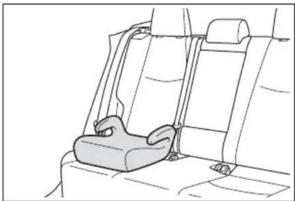
natural_image
Line drawing of a car seatbelt with a seatbelt resting inside, no text or symbols present▶ High back type
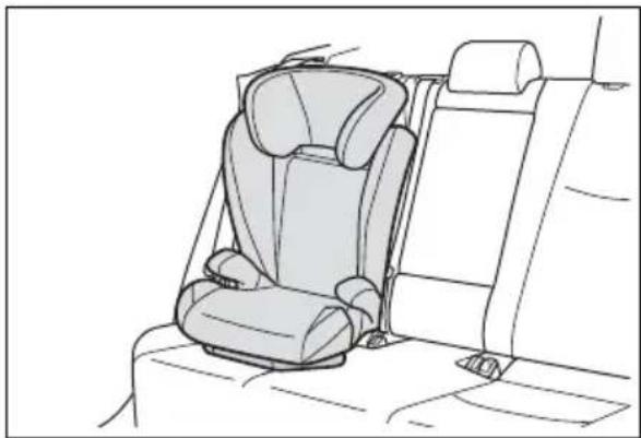
natural_image
Line drawing of a car backseat with seat, seats, and rear seats (no text or symbols)4 Sit the child in the child restraint system. Fit the seat belt to the child restraint system according to the manufacturer's instructions and insert the plate into the
buckle. Make sure that the belt is not twisted.
Check that the shoulder belt is correctly positioned over the child's shoulder and that the lap belt is as low as possible. (→P.31)
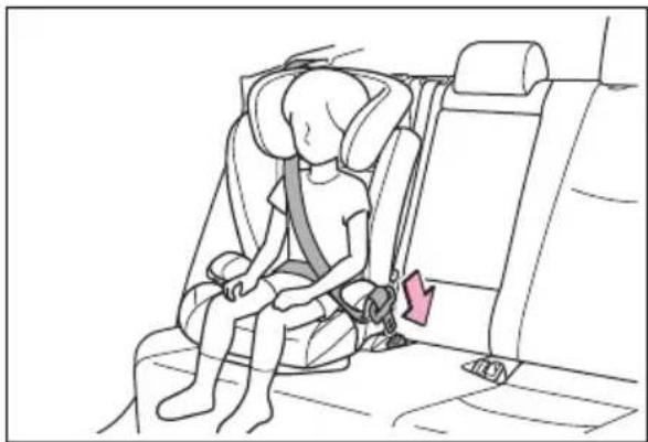
natural_image
Line drawing of a child wearing a car seatbelt, sitting inside a vehicle (no text or symbols)■Removing a child restraint system installed with a seat belt
Press the buckle release button and fully retract the seat belt.
When releasing the buckle, the child restraint system may spring up due to the rebound of the seat cushion. Release the buckle while holding down the child restraint system.
Since the seat belt automatically reels itself, slowly return it to the stowing position.
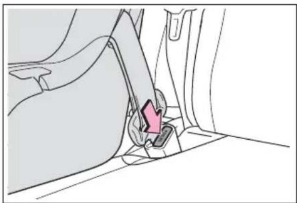
natural_image
Diagram of a car seatbelt mechanism showing a highlighted grip and seat (no text or symbols)
WARNING
■When installing a child restraint system
Observe the following precautions.
Failure to do so may result in death or serious injury.
- Do not allow children to play with the seat belt. If the seat belt becomes twisted around a child's neck, it may lead to choking or other serious injuries that could result in death. If this occurs and the buckle cannot be unfastened, scissors should be used to cut the belt.
● Ensure that the belt and plate are securely locked and the seat belt is not twisted.
● Shake the child restraint system left and right, and forward and backward to ensure that it has been securely installed.
●After securing a child restraint system, never adjust the seat. - When a booster seat is installed, always ensure that the shoulder belt is positioned across the center of the child's shoulder. The belt should be kept away from the child's neck, but not so that it could fall off the child's shoulder.
● Follow all installation instructions provided by the child restraint system manufacturer.

WARNING
- When securing some types of child restraint systems in rear seats, it may not be possible to properly use the seat belts in positions next to the child restraint without interfering with it or affecting seat belt effectiveness. Be sure your seat belt fits snugly across your shoulder and low on your hips. If it does not, or if it interferes with the child restraint, move to a different position. Failure to do so may result in death or serious injury.
- When installing a child restraint system in the center rear seat, adjust both seatbacks at the same angle. Otherwise, the child restraint system cannot be securely restrained and this may cause death or serious injuries in the event of sudden braking, sudden swerving or an accident.
■When installing a booster seat
To prevent the belt from going into ALR lock mode, do not fully extend the shoulder belt. ALR mode causes the belt to tighten only. This could cause injury or discomfort to the child. (→P.33)
■ Do not use a seat belt extender
If a seat belt extender is used when installing a child restraint system, the seat belt will not securely hold the child restraint system, which could cause death or serious injury to the child or other passengers in the event of sudden braking, sudden swerving or an accident.
Child restraint system fixed with a child restraint LATCH anchor
■Child restraint LATCH anchors
LATCH anchors are provided for the outboard rear seats.
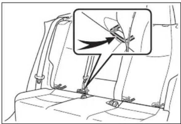
natural_image
Diagram of a car seat with a magnified inset showing a mechanical component (no text or symbols present)■When installing in the rear outboard seats
Install the child restraint system in accordance to the operation manual enclosed with the child restraint system.
1 Adjust the seat.
If there is a gap between the child restraint system and the seatback, adjust the seatback angle until good contact is achieved.
2 If the head restraint interferes with the child restraint system installation and the head restraint can be removed,
remove the head restraint. (→P.160)
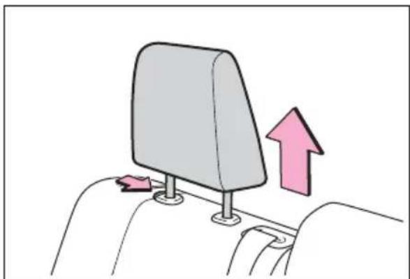
natural_image
Diagram of a car seatbelt mechanism with a pink upward arrow indicating direction (no text or symbols)▶ With flexible lower attachments
3 Latch the hooks of the lower attachments onto the LATCH anchors.
For owners in Canada:
The symbol on a child
restraint system indicates A
the presence of a lower connector system.
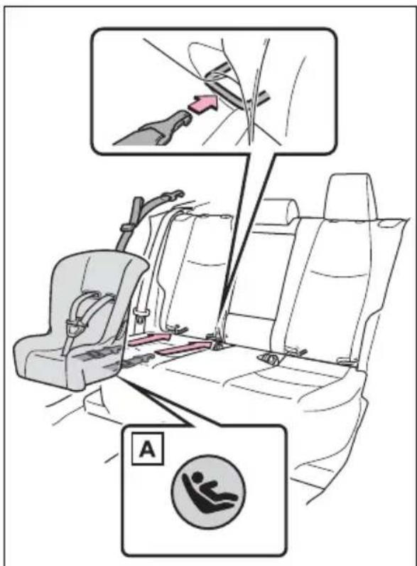
text_image
Diagram illustrating car seatbelting instructions with labeled parts and safety symbols▶ With rigid lower attachments
3 Latch the buckles onto the LATCH anchors.
For owners in Canada:
The symbol on a child
restraint system indicates A the presence of a lower connector system.
text_image
Diagram illustrating car seatbelting instructions with labeled parts and safety symbols4 If the child restraint has a top tether strap, follow the child restraint manufacturer's operation manual regarding the installation, using the top tether strap to latch onto the top tether strap anchor. (→P.63)
5 After installing the child restraint system, rock it back and forth to ensure that it is installed securely. (→P.60)
■When installing in the rear center seat
There are no LATCH anchors behind the rear center seat. However, the inboard LATCH anchors of the outboard seats, which are 17.3 in. (440 mm) apart, can be used if the child restraint system manufacturer's instructions permit use of those anchors with the anchor spacing stated.
Child restraint systems with rigid lower attachments cannot be installed in the center seat. This type of child restraint system can only be installed in the out-board seat.
■Laws and regulations pertaining to anchors
The LATCH system conforms to FMVSS225 or CMVSS210.2. Child restraint systems conforming to FMVSS213 or CMVSS213 specifications can be used. This vehicle is designed to conform to SAE J1819.

WARNING
■When installing a child restraint system
Observe the following precautions. Failure to do so may result in death or serious injury.
- When using the LATCH anchors, be sure that there are no foreign objects around the anchors and that the seat belt is not caught behind the child restraint system.
● Follow all installation instructions provided by the child restraint system manufacturer.
● Never attach two child restraint system attachments to the same anchor. In a collision, one anchor may not be strong enough to hold two child restraint system attachments and may break.
If the LATCH anchors are already in use, use the seat belt to install a child restraint system in the center seat.
- When securing some types of child restraint systems in rear seats, it may not be possible to properly use the seat belts in positions next to the child restraint without interfering with it or affecting seat belt effectiveness. Be sure your seat belt fits snugly across your shoulder and low on your hips. If it does not, or if it interferes with the child restraint, move to a different position. Failure to do so may result in death or serious injury.
- If the seat is adjusted, reconfirm the security of the child restraint system.
Using an anchor bracket (for top tether strap)
■ Anchor brackets (for top tether strap)
Anchor brackets are provided for each rear seat.
Use anchor brackets when fixing the top tether strap.
▶ Outboard rear seats
text_image
TOP-TETHER A BA Anchor brackets
B Top tether strap
▶ Center rear seat
text_image
TOP-TETHER CENTER SEAT A BA Anchor bracket
B Top tether strap
■Fixing the top tether strap to the anchor bracket
Install the child restraint system in accordance to the operation manual enclosed with the child restraint system.
▶ Outboard rear seats
1 Remove the head restraint. (→P.160)
natural_image
Illustration of a car seatbelt with a pink upward arrow indicating direction (no text or symbols)2 Latch the hook onto the anchor bracket and tighten the top tether strap.
Make sure the top tether strap is securely latched. (→P.60)
text_image
B AA Hook
B Top tether strap
3 If the head restraint does not interfere with the child
restraint system installation, install the head restraint.
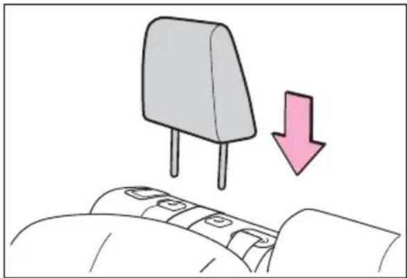
natural_image
Illustration of a pink downward arrow pointing to a gray electronic component on a bed (no text or symbols)▶ Center rear seat
1 Adjust the head restraint to the upmost position.
If the head restraint interferes with your child restraint system, and the head restraint can be removed, remove the head restraint. (→P.160)
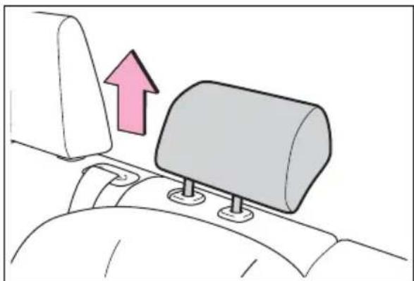
natural_image
Diagram showing a vehicle's seatbelt mechanism with an upward arrow, no text or symbols present2 Latch the hook onto the anchor bracket and tighten the top tether strap.
Make sure the top tether strap is securely latched.
When installing the child restraint system with the head restraint being raised, be sure to have the top tether strap pass underneath the head restraint.
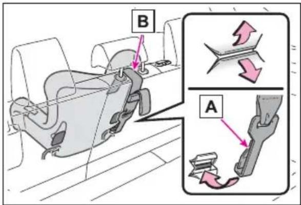
text_image
B AA Hook
B Top tether strap
■Laws and regulations pertaining to anchors
The LATCH system conforms to FMVSS225 or CMVSS210.2.
Child restraint systems conforming to FMVSS213 or CMVSS213 specifications can be used.
This vehicle is designed to conform to SAE J1819.

WARNING
■When installing a child restraint system
Observe the following precautions.
Failure to do so may result in death or serious injury.
● Firmly attach the top tether strap and make sure that the belt is not twisted.
- Do not attach the top tether strap to anything other than the anchor bracket.
●After securing a child restraint system, never adjust the seat.
● Follow all installation instructions provided by the child restraint system manufacturer.

WARNING
● Center rear seat: When installing the child restraint system with the head restraint being raised, after the head restraint has been raised and then the anchor bracket has been fixed, do not lower the head restraint.
Safety Connect\*
*: If equipped
Safety Connect is a subscription-based telematics service that uses Global Positioning System (GPS) data and embedded cellular technology to provide safety and security features to subscribers. Safety Connect is supported by Toyota's designated response center, which operates 24 hours per day, 7 days per week.
Safety Connect service is available by subscription on select, telematics hardware-equipped vehicles.
By using the Safety Connect service, you are agreeing to be bound by the Telematics Subscription Service Agreement and its Terms and Conditions, as in effect and amended from time to time, a current copy of which is available at Toyota.com in the United States, Toyotapr.com in Puerto Rico and Toyota.ca in Canada. All use of the Safety Connect service is subject to such then-applicable Terms and Conditions.
System components
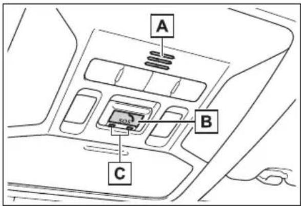
text_image
A B CA Microphone
B "SOS" button
C LED light indicators
■Certification for the Safety Connect
FCC ID: BEJTL19BNN
IC: 2703H-TL19BNN
FCC/IC WARNING:
Changes or modifications not expressly approved by the manufacture could void the user's authority to operate the equipment.
This device complies with Part 15 of the FCC Rules and Industry Canada license-exempt RSS standards. Operation is subject to the following two conditions:
(1) this device may not cause harmful interference, and
(2) this device must accept any interference, including interference that may cause undesired operation of the device.
This equipment complies with IC RSS-102 radiation exposure limits set forth for uncontrolled environment.
The antennas used for this transmitter must be installed to provide a separation distance of least 20cm from all persons.
FCC/IC AVERTISSEMENT:
Subscribers have the following Safety Connect services available:
● Automatic Collision Notification*
Helps drivers receive necessary response from emergency service providers. (→P.70)
*: U.S. Patent No. 7,508,298 B2
● Stolen Vehicle Location
Helps drivers in the event of vehicle theft. (→P.70)
● Emergency Assistance Button
("SOS")
Connects drivers to response-center support. ( P.70)
● Enhanced Roadside Assistance
Provides drivers various on-road assistance. ( P.71)
Subscription
After you have signed the Telematics Subscription Service Agreement and are enrolled, you can begin receiving services.
A variety of subscription terms are available for purchase. Contact your Toyota dealer, call the following appropriate Customer Experience Center or push the "SOS" button in your vehicle for further subscription details.
● The United States
1-800-331-4331
- Canada
1-888-869-6828
- Puerto Rico
1-877-855-8377
■Safety Connect Services Information
- Phone calls using the vehicle's Bluetooth® technology will not be possible when Safety Connect is active and in use.
●Safety Connect is available beginning Fall 2009 on select Toyota models (in the contiguous United States only). Contact with the Safety Connect response center
is dependent upon the telematics device being in operative condition, cellular connection availability, and GPS satellite signal reception, which can limit the ability to reach the response center or receive emergency service support. Enrollment and Telematics Subscription Service Agreement are required. A variety of subscription terms are available; charges vary by subscription term selected and location.
●Automatic Collision Notification, Emergency Assistance and Stolen Vehicle Location are available in the United States, including Hawaii and Alaska, Puerto Rico and Canada, and Enhanced Roadside Assistance are available in the United States, Puerto Rico and Canada.
●Automatic Collision Notification, Emergency Assistance, Stolen Vehicle and Enhanced Road Assistance are not available in the U.S. Virgin Islands. For vehicles first sold in the U.S. Virgin Islands, no Safety Connect services will function in or outside the U.S. Virgin Islands.
●Safety Connect services are not subject to section 255 of the Telecommunications Act and the device is not TTY compatible.
Languages
The Safety Connect response center will offer support in multiple languages. The Safety Connect system will offer voice prompts in English, Spanish, and French. Please indicate your language of choice when enrolling.
■When contacting the response center
You may be unable to contact the response center if the network is busy.
Safety Connect LED light Indicators
When the power switch is turned to ON, the red indicator light comes on for 2 seconds then turns off. Afterward, the green indicator light comes on, indicating that the service is active.
The following indicator light patterns indicate specific system usage conditions:
● Green indicator light on = Active service
● Green indicator light flashing = Safety Connect call in process
- Red indicator light (except at vehicle start-up) = System malfunction (contact your Toyota dealer)
- No indicator light (off) = Safety Connect service not active
Safety Connect services
■Automatic Collision Notification
In case of either airbag deployment or severe rear-end collision, the system is designed to automatically call the response center. The responding agent receives the vehicle's location and attempts to speak with the vehicle occupants to assess the level of emergency. If the occupants are unable to communicate, the agent automatically treats the call as an emergency, contacts the nearest emergency services provider to describe the situation, and requests that assistance be sent to the location.
■Stolen Vehicle Location
If your vehicle is stolen, Safety Connect can work with local authorities to assist them in locating and recovering the vehicle. After filing a police report, call the Customer Experience Center at 1-800-331-4331 in the United States, 1-877-855-8377 in Puerto Rico or 1-888-869-6828 in Canada, and follow the prompts for Safety Connect to initiate this service.
In addition to assisting law enforcement with recovery of a stolen vehicle, Safety-Connect-equipped vehicle location data may, under certain circumstances, be shared with third parties to locate your vehicle. Further information is available at Toyota.com in the United States, Toyotapr.com in Puerto Rico and Toyota.ca in Canada.
Emergency Assistance Button ("SOS")
In the event of an emergency on the road, push the "SOS" button to reach the Safety Connect response center. The answering agent will determine your vehi-
cle's location, assess the emergency, and dispatch the necessary assistance required.
If you accidentally press the "SOS" button, tell the response-center agent that you are not experiencing an emergency.
■Enhanced Roadside Assistance
Enhanced Roadside Assistance adds GPS data to the already included warranty-based Toyota roadside service.
Subscribers can press the "SOS" button to reach a Safety Connect response-center agent, who can help with a wide range of needs, such as: towing, flat tire, fuel delivery, etc. For a description of the Enhanced Roadside Assistance services and their limitations, please see the Safety Connect Terms and Conditions, which are available at Toyota.com in the United States, Toyotapr.com in Puerto Rico and Toyota.ca in Canada.
Safety information for Safety Connect
Important! Read this information before using Safety Connect.
■Exposure to radio frequency signals
The Safety Connect system installed in your vehicle is a low-power radio transmitter and receiver. It receives and also sends out radio frequency (RF) signals.
In August 1996, the Federal Communications Commission (FCC) adopted RF exposure guidelines with safety levels for mobile wireless phones. Those guidelines are consistent with the safety standards previously set by the following U.S. and international standards bodies.
● ANSI (American National Standards Institute) C95.1 [1992]
● NCRP (National Council on Radiation Protection and Measurement) Report 86 [1986]
- ICNIRP (International Commission on Non-Ionizing Radiation Protection) [1996]
Those standards were based on comprehensive and periodic evaluations of the relevant scientific literature. Over 120 scientists, engineers, and physicians from universities, and government health agencies and industries reviewed the available body of research to develop the ANSI Standard (C95.1).
The design of Safety Connect complies with the FCC guidelines in addition to those standards.
Hybrid system features
Your vehicle is a hybrid vehicle. It has characteristics different from conventional vehicles. Be sure you are closely familiar with the characteristics of your vehicle, and operate it with care.
The hybrid system combines the use of a gasoline engine and an electric motor (traction motor) according to driving conditions, improving fuel efficiency and reducing exhaust emissions.
System components
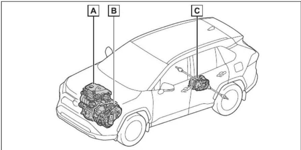
text_image
A B CThe illustration is an example for explanation and may differ from the actual item.
A Gasoline engine
B Front electric motor (traction motor)
C Rear electric motor (traction motor)
■When stopped/during start off
The gasoline engine stops* when the vehicle is stopped. During start off, the electric motor (traction motor) drives the vehicle. At slow speeds or when
traveling down a gentle slope, the engine is stopped* and the electric motor (traction motor) is used.
When the shift lever is in N, the hybrid battery (traction battery) is not being charged.
*: When the hybrid battery (traction battery) requires charging or the engine is warming up, etc., the gasoline engine will not automatically stop. (→P.73)
■During normal driving
The gasoline engine is predominantly used. The electric motor (traction motor) charges the hybrid battery (traction battery) as necessary.
■When accelerating sharply
When the accelerator pedal is depressed heavily, the power of the hybrid battery (traction battery) is added to that of the gasoline engine via the electric motor (traction motor).
■When braking (regenerative braking)
The wheels operate the electric motor (traction motor) as a power generator, and the hybrid battery (traction battery) is charged.
■Regenerative braking
In the following situations, kinetic energy is converted to electric energy and deceleration force can be obtained in conjunction with the recharging of the hybrid battery (traction battery).
●The accelerator pedal is released while driving with the shift lever in D or S.
●The brake pedal is depressed while driving with the shift lever in D or S.
■EV indicator
The EV indicator comes on when the vehicle is driven using only the electric motor (traction motor) or the gasoline engine is stopped.
The on/off operation of the EV indicator can be changed. (→P.109)
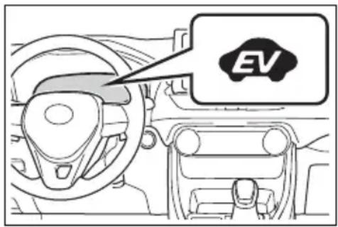
text_image
EV■ Conditions in which the gaso- line engine may not stop
The gasoline engine starts and stops automatically. However, it may not stop automatically in the following conditions*:
●During gasoline engine warm-up
● During hybrid battery (traction battery) charging
- When the temperature of the hybrid battery (traction battery) is high or low
- When the heater is switched on
*: Depending on the circumstances, the gasoline engine may also not stop automatically in other situations.
■ Charging the hybrid battery (traction battery)
As the gasoline engine charges the hybrid battery (traction battery), the battery does not need to be charged from an outside source. However, if the vehicle is left parked for a long time the hybrid battery (traction battery) will slowly discharge. For this reason, be sure to drive the vehicle at least once every few months for at least 30 minutes or 10 miles (16 km). If the hybrid battery (traction battery) becomes fully discharged and you are unable to start the hybrid system, contact your Toyota dealer.
■ Charging the 12-volt battery
→P.674
■ After the 12-volt battery has discharged or when the terminal has been removed and installed during replace, etc.
The gasoline engine may not stop even if the vehicle is being driven by the hybrid battery (traction battery). If this continues for a few days, contact your Toyota dealer.
■ Sounds and vibrations specific to a hybrid vehicle
There may be no engine sound or vibration even though the vehicle is able to move with the “READY” indicator is illuminated. For safety, make sure to shift the shift lever to P and apply the parking brake when parked.
The following sounds or vibrations may occur when the hybrid system is operating and are not a malfunction:
●Motor sounds may be heard from the engine compartment.
● Sounds may be heard from the hybrid battery (traction battery) under the rear seats when the hybrid system starts or stops.
- Relay operating sounds such as a snap or soft clank will be emitted from the hybrid battery (traction battery), under the rear seats, when the hybrid system is started or stopped.
● Sounds from the hybrid system may be heard when the back door is open.
● Sounds may be heard from the transmission when the gasoline engine starts or stops, when driving at low speeds, or during idling.
●Engine sounds may be heard when accelerating sharply.
● Sounds may be heard due to regenerative braking when the brake pedal is depressed or as the accelerator pedal is released.
●Vibration may be felt when the gasoline engine starts or stops.
●Cooling fan sounds may be heard from the air intake vent under the rear seat.
■ Maintenance, repair, recycling, and disposal
Contact your Toyota dealer regarding maintenance, repair, recycling and disposal. Do not dispose of the vehicle yourself.
Vehicle proximity notification system
When driving with the gasoline engine stopped, a sound, which changes in accordance with the driving speed, will be played in order to warn people nearby of the vehicle's approach. The sound will stop when the vehicle speed exceeds approximately 22 mph (35 km/h).
■ Vehicle proximity notification system
In the following cases, the vehicle proximity notification system may be difficult for surrounding people to hear.
In very noisy areas
●In the wind or the rain
Also, as the vehicle proximity notification system is installed on the front of the vehicle, it may be more difficult to hear from the rear of the vehicle compared to the front.
If “Proximity Notification System Malfunction Visit Your Dealer” is displayed on the multi-information display
The system may be malfunctioning. Have the vehicle inspected by your Toyota dealer.
Predictive efficient drive (vehicles with navigation system)\*
*: This function can only be used in the mainland U.S.A. It cannot be used in other states and territories, including Alaska and Hawaii.
This system operates based on the driving situation and traffic information to enhance fuel economy.
For details about Predictive efficient drive, refer to "NAVIGATION AND MULTIMEDIA SYSTEM OWNER'S MANUAL".
■Predictive deceleration support
- When the vehicle approaches to predictive deceleration support points registered in the navigation system, the “Reference operation range” (A) of the ECO Accelerator Guidance (→P.105) on the multi-information display will be turned off to encourage the driver to reduce excessive acceleration.
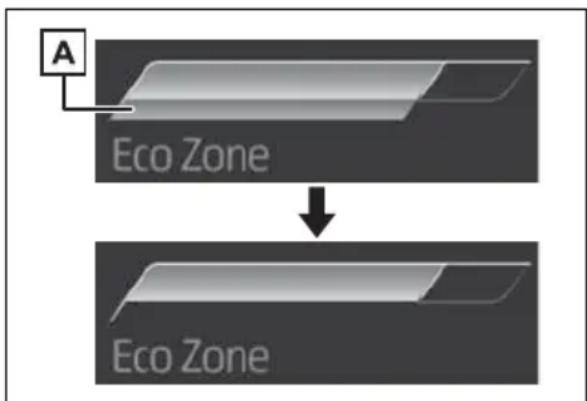
flowchart
graph TD
    A["A"] --> B["Eco Zone"]
    B --> C["Eco Zone"]
● The engine braking force will
be increased according to the driving conditions to more efficiently charge the hybrid battery (traction battery) after the accelerator pedal is released.
■Predictive SOC control
The following types of control are performed based on data such as road and traffic information during route guidance by the navigation system to help ensure that the vehicle efficiently uses electricity.
- When there is a long downhill slope along the route, the system reduces the hybrid battery (traction battery) level before reaching the slope to help ensure charging capacity for regenerative braking while traveling downhill.
- When traffic congestion is predicted along the route, the system helps ensure a certain battery level before reaching congested roads to reduce the frequency of starting the engine to charge the hybrid battery (traction battery) due to low battery levels.
Hybrid system precautions
Take care when handling the hybrid system, as it is a high voltage system (about 650V at maximum) as well as contains parts that become extremely hot when the hybrid system is operating. Obey the warning labels attached to the vehicle.
System components
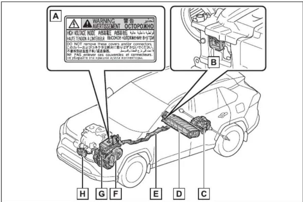
text_image
A WARNING 警告 AVERTISSEMENT OCTOPOЖНО HIGH VOLTAGE INSIDE 内部高电压 内部高电压 HAUTE TENSION A LINTEREUR BICOKOE HAPRAJNME BHUTRI DO NOT remove these covers and/or connectors. このカバーおよびコネクタは絶対に取りはずさないでください. 不要断型送类電子和/或连接器。 NE PAS enlever ces couvercles et connecteurs. не убирайте эти комплия и/или коннекторы. B H G F E D CThe illustration is an example for explanation and may differ from the actual item.
A Warning label
B Service plug
C Rear electric motor (traction motor)
D Hybrid battery (traction battery)
E High voltage cables (orange)
F Front electric motor (traction motor)
G Power control unit
H Air conditioning compressor
Running out of fuel
When the vehicle has run out of fuel and the hybrid system cannot be started, refuel the vehicle with at least enough gasoline to make the low fuel level warning light ( P.649) go off. If there is only a small amount of fuel, the hybrid system may not be able to start. (The standard amount of fuel is about 2.3 gal. [8.8 L, 1.9 Imp.gal.], when the vehicle is on a level surface. This value may vary when the vehicle is on a slope. Add extra fuel when the vehicle is inclined.)
Electromagnetic waves
● High voltage parts and cables on hybrid vehicles incorporate electromagnetic shielding, and therefore emit approximately the same amount of electromagnetic waves as conventional gasoline powered vehicles or home electronic appliances.
- Your vehicle may cause sound interference in some third party-produced radio parts.
■Hybrid battery (traction battery)
The hybrid battery (traction battery) has a limited service life. The lifespan of the hybrid battery (traction battery) can change in accordance with driving style and driving conditions.
■ Starting the hybrid system in an extremely cold environment
When the hybrid battery (traction battery) is extremely cold (below approximately -22^ [-30^] ) under the influence of the outside temperature, it may not be possible to start the hybrid system. In this case, try to start the hybrid system again after the temperature of the hybrid battery increases due to the outside temperature increase etc.

WARNING
■High voltage precautions
This vehicle has high voltage DC and AC systems as well as a 12-volt system. DC and AC high voltage is very dangerous and can cause severe burns and electric shock that may result in death or serious injury.
● Never touch, disassemble, remove or replace the high voltage parts, cables or their connectors.
●The hybrid system will become hot after starting as the system uses high voltage. Be careful of both the high voltage and the high temperature, and always obey the warning labels attached to the vehicle.
● Never try to open the service plug access hole located underneath the rear seats. The service plug is used only when the vehicle is serviced and is subject to high voltage.
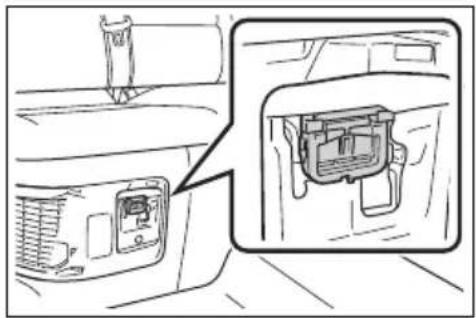
natural_image
Diagram showing a car interior with a mounted device and a close-up view of the internal components (no text or symbols)■Road accident cautions
Observe the following precautions to reduce the risk of death or serious injury:
● Pull your vehicle off the road, shift the shift lever to P, apply the parking brake, and turn the hybrid system off.
- Do not touch the high voltage parts, cables and connectors.

WARNING
- If electric wires are exposed inside or outside your vehicle, an electric shock may occur. Never touch exposed electric wires.
- If a fire occurs in the hybrid vehicle, leave the vehicle as soon as possible. Never use a fire extinguisher that is not meant for electric fires. Using even a small amount of water may be dangerous.
- If your vehicle needs to be towed, do so with four wheels raised. If the wheels connected to the electric motor (traction motor) are on the ground when towing, the motor may continue to generate electricity. This may cause a fire. ( P.637)
Carefully inspect the ground under the vehicle. If you find that liquid has leaked onto the ground, the fuel system may have been damaged. Leave the vehicle as soon as possible.
▶ AXAH54L models* - If a fluid leak occurs, do not touch the fluid as it may be strong alkaline electrolyte from the hybrid battery (traction battery). If it comes into contact with your skin or eyes, wash it off immediately with a large amount of water or, if possible, boric acid solution. Seek immediate medical attention.
*: The model code is indicated on the Certification Regulation Label. (→P.684)
AXAL54L models*
- Do not touch the battery if liquid is leaking from or adhering to it. If electrolyte (carbonic-based organic electrolyte) from the hybrid battery (traction battery) comes into contact with the eyes or skin, it could cause blindness or skin wounds. In the unlikely event that it comes into contact with the eyes or skin, wash it off immediately with a large amount of water, and seek immediate medical attention.
- If electrolyte is leaking from the hybrid battery (traction battery), do not approach the vehicle. Even in the unlikely event that the hybrid battery (traction battery) is damaged, the internal construction of the battery will prevent a large amount of electrolyte from leaking out. However, any electrolyte that does leak out will give off a vapor. This vapor is an irritant to skin and eyes and could cause acute poisoning if inhaled.
- Do not bring burning or high-temperature items close to the electrolyte.
The electrolyte may ignite and cause a fire.
*: The model code is indicated on the Certification Regulation Label. (→P.684)
■ Hybrid battery (traction battery)
●AXAL54L models*: Your vehicle contains a sealed lithium-ion battery.
*: The model code is indicated on the Certification Regulation Label. (→P.684)

WARNING
- Never resell, hand over or modify the hybrid battery. To prevent accidents, hybrid batteries that have been removed from a disposed vehicle are collected through Toyota dealer. Do not dispose of the battery yourself.
Unless the battery is properly collected, the following may occur, resulting in death or serious injury:
- The hybrid battery may be illegally disposed of or dumped, and it is hazardous to the environment or someone may touch a high voltage part, resulting in an electric shock.
- The hybrid battery is intended to be used exclusively with your hybrid vehicle. If the hybrid battery is used outside of your vehicle or modified in any way, accidents such as electric shock, heat generation, smoke generation, an explosion and electrolyte leakage may occur.
When reselling or handing over your vehicle, the possibility of an accident is extremely high because the person receiving the vehicle may not be aware of these dangers.
- If your vehicle is disposed of without the hybrid battery having been removed, there is a danger of serious electric shock if high voltage parts, cables and their connectors are touched. In the event that your vehicle must be disposed of, the hybrid battery must be disposed of by your Toyota dealer or a qualified service shop. If the hybrid battery is not disposed of properly, it may cause electric shock that can result in death or serious injury.
Hybrid battery (traction battery) air intake vent
There is an air intake vent under the right side of the rear seat for the purpose of cooling the hybrid battery (traction battery). If the vent is blocked, charging/discharging of the hybrid battery (traction battery) may become limited.
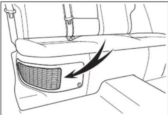
natural_image
Line drawing of a car interior showing the front and side views of a vehicle (no text or symbols)
NOTICE
■ Hybrid battery (traction battery) air intake vent
- Make sure not to block the air intake vent with anything, such as a seat cover, plastic cover, or luggage. If the vent is blocked, the charging/discharging of the hybrid battery (traction battery) may become limited.
- When dust etc. has accumulated in the air intake vent, clean it with a vacuum cleaner to prevent the vent from clogging.
- Clean the air intake vent regularly to prevent the charging/discharging of the hybrid battery (traction battery) from being restricted.

NOTICE
- Do not get water or foreign materials in the air intake vent as this may cause a short circuit and damage the hybrid battery (traction battery).
- Do not carry large amounts of water such as water cooler bottles in the vehicle. If water spills onto the hybrid battery (traction battery), the battery may be damaged. Have the vehicle inspected by your Toyota dealer.
There is a filter installed to the air intake vent. When the filter remains noticeably dirty even after cleaning the air intake vent, filter cleaning or replacement is recommended. For information regarding filter cleaning or replacement, refer to P.611. - If “Maintenance Required for Traction Battery Cooling Parts See Owner’s Manual” is shown on the multi-information display, the air intake vent and filter may be clogged. Refer to P.611for information on how to clean the air intake vent.
Emergency shut off sys- tem
When a certain level of impact is detected by the impact sensor, the emergency shut off system blocks the high voltage current and stops the fuel pump to minimize the risk of electrocution and fuel leakage. If the emergency shut off system activates, your vehicle will not restart. To restart the hybrid system, contact your Toyota dealer.
Hybrid warning message
A message is automatically displayed when a malfunction occurs in the hybrid system or an improper operation is attempted.
If a warning message is shown on the multi-information display, read the message and follow the instructions.
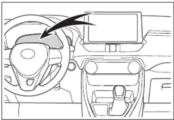
natural_image
Interior view of a car dashboard and steering wheel (no text or symbols visible)If a warning light comes on, a warning message is displayed, or the 12-volt battery is disconnected
The hybrid system may not start. In this case, try to start the system again. If the “READY” indicator does not come on, contact your Toyota dealer.
Immobilizer system
The vehicle's keys have built-in transponder chips that prevent the hybrid system from starting if a key has not been previously registered in the vehicle's on-board computer.
Never leave the keys inside the vehicle when you leave the vehicle.
This system is designed to help prevent vehicle theft but does not guarantee absolute security against all vehicle thefts.
Operating the system
▶ Vehicles without smart key system
The indicator light flashes after the key has been removed from the power switch to indicate that the system is operating. The indicator light goes off after the registered key has been inserted into the power switch to indicate that the system has been canceled.
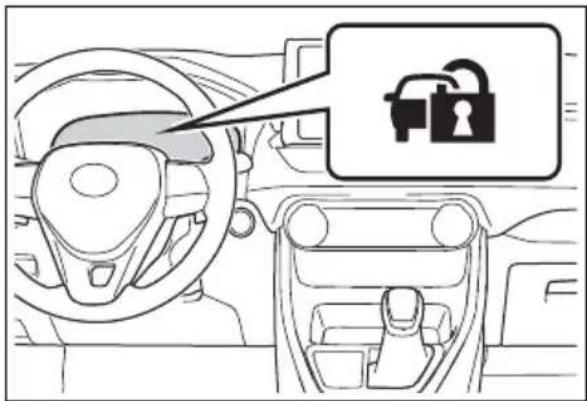
text_image
Diagram showing car interior with dashboard, steering wheel, and lock icon labeled in Chinese▶ Vehicles with smart key system
The indicator light flashes after the power switch has been turned to OFF to indicate that the system is operating. The indicator light goes off after the power switch has been turned to ACC or ON to indicate that the system has been canceled.
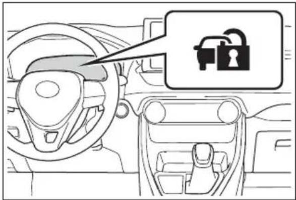
text_image
Diagram showing car interior with steering wheel, dashboard, and lock icon labeled in ChineseSystem maintenance
The vehicle has a maintenance-free type immobilizer system.
■ Conditions that may cause the system to malfunction
- If the grip portion of the key is in contact with a metallic object
- If the key is in close proximity to or touching a key to the security system (key with a built-in transponder chip) of another vehicle
■Certification for the immobilizer system
For vehicles sold in the U.S.A., Hawaii, American Samoa, Guam, Saipan and Puerto Rico
FCC ID:MOZRI-57BTY
This device complies with part 15 of the FCC Rules. Operation is subject to the following two conditions: (1) This device may not cause harmful interference, and (2) this device must accept any interference received, including interference that may cause undesired operation.
Changes or modifications not expressly approved by the party responsible for compliance could void the user's authority to operate the equipment.
FCC ID: NI4TMIMB-3
This device complies with part 15 of the FCC Rules. Operation is subject to the following two conditions: (1) This device may not cause harmful interference, and (2) this device must accept any interference received, including interference that may cause undesired operation.
Changes or modifications not expressly approved by the party responsible for compliance could void the user's authority to operate the equipment.
For vehicles sold in Canada
This device complies with Industry Canada's licence-exempt RSSs. Operation is subject to the following two conditions: (1) This device may not cause interference; and (2) This device must accept any interference, including interference that may cause undesired operation of the device.
This device complies with Industry Canada's licence-exempt RSSs. Operation is subject to the following two conditions: (1) This device may not cause interference; and (2) This device must accept any interference, including interference that may cause undesired operation of the device.
■To ensure the system operates correctly
Do not modify or remove the system. If modified or removed, the proper operation of the system cannot be guaranteed.
Alarm
*: If equipped
The alarm uses light and sound to give an alert when an intrusion is detected.
The alarm is triggered in the following situations when the alarm is set:
- Vehicles without smart key system: A locked door is unlocked or opened in any way other than using the wireless remote control or key. (The doors will lock again automatically.)
- Vehicles with smart key system: A locked door is unlocked or opened in any way other than using the entry function, wireless remote control or mechanical key. (The doors will lock again automatically.)
● The hood is opened.
Setting/canceling/stop- ping the alarm system
■Items to check before locking the vehicle
To prevent unexpected triggering of the alarm and vehicle theft, make sure of the following:
- Nobody is in the vehicle.
● The side windows and moon roof (if equipped) or pan-
oramic moon roof (if equipped) are closed before the alarm is set.
- No valuables or other personal items are left in the vehicle.
Setting
Close the doors and hood, and lock all the doors. The system will be set automatically after 30 seconds.
The security indicator changes from being on to flashing when the system is set.
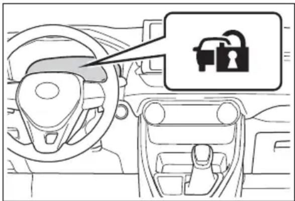
text_image
Diagram showing a car interior with a lock icon and a speech bubble pointing to the lock symbol.■Canceling or stopping
Do one of the following to deactivate or stop the alarm:
- Unlock the doors.
- Turn the power switch to ACC or ON, or start the hybrid system. (The alarm will be deactivated or stopped after a few seconds.)
System maintenance
The vehicle has a maintenance-free type alarm system.
■Triggering of the alarm
The alarm may be triggered in the following situations:
(Stopping the alarm deactivates the alarm system.)
● A person inside the vehicle opens a door or hood, or unlocks the vehicle using an inside lock button.
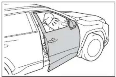
natural_image
Line drawing of a car door open showing a person inside (no text or symbols)●The 12-volt battery is recharged or replaced when the vehicle is locked. (→P.672)
natural_image
Line drawing of a car seatbelt with hands inserting a component (no text or symbols)■Alarm-operated door lock
In the following cases, depending on the situation, the door may automatically lock to prevent improper entry into the vehicle:
- When a person remaining in the vehicle unlocks the door and the alarm is activated.
●While the alarm is activated, a person remaining in the vehicle unlocks the door. - When recharging or replacing the 12-volt battery.
■Customization (Canada only)
The alarm can be set to activate when the key (vehicles without smart key system) or mechanical key (vehicles with smart key system) is used to unlock. (Customizable features: →P.707)

NOTICE
■To ensure the system operates correctly
Do not modify or remove the system. If modified or removed, the proper operation of the system cannot be guaranteed.
2
2-1. Instrument cluster
Warning lights and indicators 88
Gauges and meters (with 4.2-inch display)....94
Gauges and meters (with 7-inch display) .....98
Multi-information display 103
Energy monitor/consumption screen.... 113
Warning lights and indicators
The warning lights and indicators on the instrument cluster, center panel and outside rear view mirrors inform the driver of the status of the vehicle's various systems.
Instrument cluster
For the purpose of explanation, the following illustrations display all warning lights and indicators illuminated.
■With 4.2-inch display
text_image
READY RSTM RCTA POT OFF OFF SET REAR PARK ABS HOLD BRAKE (H) HOLD #DThe units used on the meters and some indicators may differ depending on the target region.
■With 7-inch display
The display of the speedometer can be selected from two types, analog or digital. ( P.109)
When analog speedometer is displayed
text_image
ABS BRAKE PARK SET OFF CHANGE MODE ECO BEANS RECTA BSM OFF OFF OFF HOLD HOLDThe units used on the meters and some indicators may differ depending on the target region.
When digital speedometer is displayed
text_image
ABS BRAKE PARK SET ECO EV MODE BEAVY REAR BSM RCTA OFF HOLDThe units used on the meters and some indicators may differ depending on the target region.
Warning lights
Warning lights inform the driver of malfunctions in the indicated vehicle's systems.
(U.S.A.)
Brake system warning light ^*1 (→P.642)
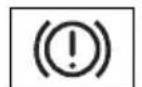
(Canada) (Red)
Brake system warning light ^*1 (→P.642)
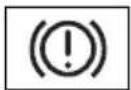
(Yellow)
Brake system warning light ^*1 (→P.642)
Charging syste warning light*1 (→P.642)
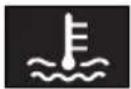
High coolant temperature warning light ^*2 (→P.643)
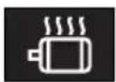
Hybrid system over- heat warning light ^*2 (→P.643)
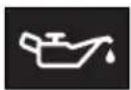
Low engine oil pressure warning light ^*2 (→P.643)
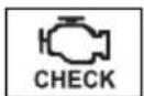
(U.S.A.)
Malfunction indicator lamp ^*1 (→P.643)
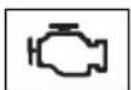
(Canada)
Malfunction indicator lamp ^*1 (→P.643)
SRS warning light ^*1 (→P.644)
(U.S.A.)
ABS warning light ^*1 (→P.644)
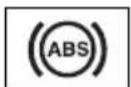
(Canada)
ABS warning light ^*1 (→P.644)
(Red/yellow)
Electric power steering system warning light ^*1 (→P.644)
(Flashes or illuminates)
PCS warning light ^*1 (→P.645)
(Orange)
LTA indicator ( P.645)

(Flashes)
(Flashes)

(Flashes)
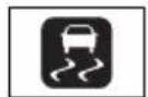

(Flashes)

(U.S.A.)
(Flashes)

(Canada)
(Flashes)
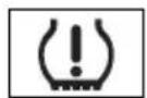
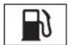
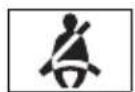
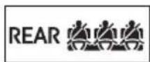
Intuitive parking assist OFF indicator ^*3 (if equipped) ( P.646)
PKSB OFF indicator ^*1 (if equipped) ( P.646)
RCTA OFF indicator ^*1 (if equipped) ( P.647)
Slip indicator light ^*1 (→P.647)
Brake Override System/Drive-Start Control/PKSB (if equipped) warning light ^*2 (→P.648)
Brake hold operated indicator ^*1 (→P.648)
Parking brake indicator (→P.648)
Parking brake indicator (→P.648)
Tire pressure warning light ^*1 (if equipped) ( P.649)
Low fuel level warning light ( P.649)
Driver's and front passenger's seat belt reminder light (→P.649)
Rear passengers' seat belt reminder lights (if equipped) (→P.650)
*1: These lights turn on when the power switch is turned to ON to
indicate that a system check is being performed. They will turn off after the hybrid system is on, or after a few seconds. There may be a malfunction in a system if the light does not come on, or turn off. Have the vehicle inspected by your Toyota dealer.
*2: This light illuminates on the multi-information display with a message.
*3:Intuitive parking assist OFF indicator turns on when the power switch is turned to ON while the Intuitive parking assist function is on. It will turn off after a few seconds.

WARNING
If a safety system warning light does not come on
Should a safety system light such as the ABS and SRS warning light not come on when you start the hybrid system, this could mean that these systems are not available to help protect you in an accident, which could result in death or serious injury. Have the vehicle inspected by your Toyota dealer immediately if this occurs.
Indicators
The indicators inform the driver of the operating state of the vehicle's various systems.
Turn signal indicator ( P.223)
Headlight indicator ( P.229)
(U.S.A.)
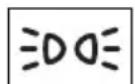
Tail light indicator ( P.229)
(Canada)
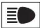
Headlight high beam indicator ( P.232)
Automatic High Beam indicator ( P.232)

Fog light indicator (if equipped) ( P.235)

Smart key system indicator ^*1 (if equipped) ( P.212)
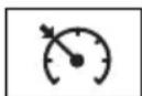
Cruise control indicator ( P.271)
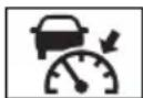
Dynamic radar cruise control indicator ( P.271)

Cruise control "SET" indicator ( P.271)
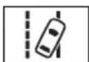
LTA indicator ^*2 (→P.263)

Intuitive parking assist OFF indicator ^*3,4 (if equipped) ( P.293)
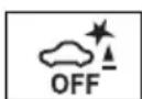
PKSB OFF indicator ^*3,5 (if equipped) ( P.299)
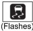
Slip indicator light ^*5 (→P.370)
VSC OFF indicator ^3,5 (→P.370)
PCS warning light ^*3,5 (→P.252)
BSM outside rear view mirror indicators ^*5,6 (if equipped) ( P.283)

BSM indicator (if equipped) ( P.283)

RCTA OFF indicator ^*3,5 (if equipped) ( P.283)

Brake hold standby indicator ^*5 (→P.227)

Brake hold operated indicator ^*5 (→P.227)
Security indicator ( P.81, 84)
"READY" indicator (→P.210, 212)

Low outside temperature indicator ^*7 (→P.95, 101)
EV indicator ( P.73)

Parking brake indicator ( P.224)
(U.S.A.)

Parking brake indicator ( P.224)
(Canada)

EV drive mode indicator ( P.217)

Eco drive mode indicator ( P.366)

Sport mode indicator ( P.366)

Trail Mode indicator ( P.367)
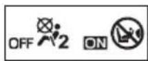
"AIR BAG ON/OFF" indicator*5,8 (→P.45)
*1: This light illuminates on the multi-information display with a message.
*2: Depending on the operating conditions of the system, the color and state (illuminated/blinking) of the indicator change.
*3: The light comes on when the system is turned off.
*4:Intuitive parking assist OFF indicator turns on when the power switch is turned to ON while the Intuitive parking assist function is on. It will turn off after a few seconds.
*5: These lights turn on when the power switch is turned to ON to indicate that a system check is being performed. They will turn off after the hybrid system is on, or after a few seconds. There may be a malfunction in a system if the lights do not turn on, or turn off. Have the vehicle inspected by your Toyota dealer.
*6: This light illuminates on the outside rear view mirrors.
*7: When the outside temperature is approximately 37^ F (3°C) or lower, the indicator will flash for approximately 10 seconds, then stay on.
*8: This light illuminates on the center panel.
■BSM (Blind Spot Monitor) outside rear view mirror indicators (if equipped)
In order to confirm operation, the BSM outside rear view mirror indicators illuminate in the following situations:
- When the power switch is turned to ON while the BSM function is
enabled on the screen of the multi-information display.
●When the BSM function is
enabled on the screen of the multi-information display while the power switch is in ON.
If the system is functioning correctly, the BSM outside rear view mirror indicators will turn off after a few seconds.
If the BSM outside rear view mirror indicators do not illuminate or do not turn off, there may be a malfunction in the system. If this occurs, have the vehicle inspected by your Toyota dealer.
Gauges and meters (with 4.2-inch display)
The meters display various drive information.
Meter display
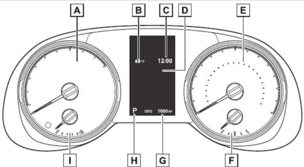
text_image
A B C D E 68°F 12:00 P 000 1000ml I H G FThe units used on the meter and display may differ depending on the target region.
A Hybrid System Indicator
Displays the Hybrid System Indicator ( P.95)
B Outside temperature ( P.95)
C Clock ( P.97)
D Multi-information display
Presents the driver with a variety of driving-related data ( P.103)
Displays warning messages if a malfunction occurs ( P.654)
E Speedometer
Displays the vehicle speed
F Fuel gauge
Displays the quantity of fuel remaining in the tank
G Odometer and trip meter
Odometer:
Displays the total distance that the vehicle has been driven
Trip meter:
Displays the distance the vehicle has been driven since the meter was last
reset. Trip meters "A" and "B" can be used to record and display different distances independently.
H Shift position and shift range indicator
Displays the selected shift position or selected shift range ( P.219)
☐ Engine coolant temperature gauge
Displays the engine coolant temperature
■The meters and display illuminate when
The power switch is in ON.
Hybrid System Indicator
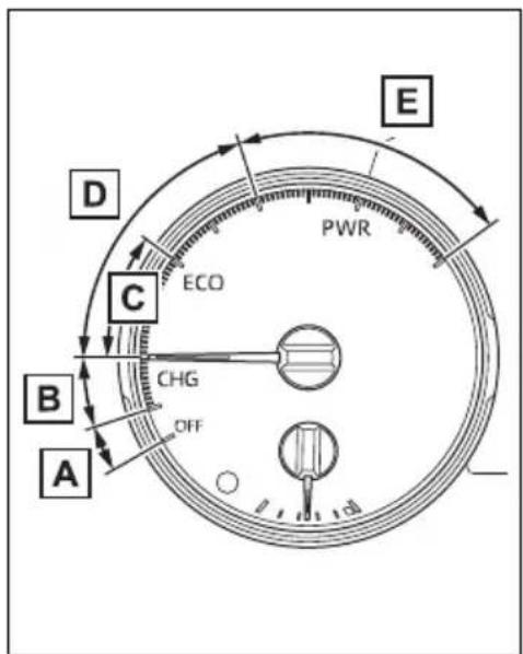
text_image
A B C D E PWR CHG OFF A B C ECO DA READY OFF area
Shows that the hybrid system is not operating.
B Charge area
Shows regeneration* status.
Regenerated energy will be used to charge the hybrid battery (traction battery).
C Hybrid Eco area
Shows that gasoline engine power is not being used very often.
The gasoline engine will automatically stop and restart under various conditions.
D Eco area
Shows that the vehicle is being driven in an Eco-friendly manner.
By keeping the indicator needle within Eco area, more Eco-friendly driving can be achieved.
E Power area
Shows that an Eco-friendly driving range is being exceeded (during full power driving etc.)
*: When used in this manual, "regeneration" refers to the conversion of energy created by the movement of the vehicle into electrical energy.
In the following situation, the Hybrid System Indicator does not operate.
●“READY” indicator is not illumi-
nated.
● The shift lever is in a range other than D or S.
■Outside temperature display
- In the following situations, the correct outside temperature may not be displayed, or the display may take longer than normal to change.
- When stopped, or driving at low speeds (less than 12 mph [20 km/h])
- When the outside temperature has changed suddenly (at the entrance/exit of a garage, tunnel, etc.)
- When “--” or “E” is displayed, the system may be malfunctioning. Take your vehicle to your Toyota dealer.
●Displays the outside temperature within the range of -40^ ( -40^ ) to 122^ ( 50^ ).
- When the outside temperature is approximately 37^ F ( 3^ C) or lower, the indicator will flash for approximately 10 seconds, then stay on.
■Liquid crystal display
→P.104

WARNING
■The information display at low temperatures
Allow the interior of the vehicle to warm up before using the liquid crystal information display. At extremely low temperatures, the display monitor may respond slowly, and display changes may be delayed.
For example, there is a lag between the driver's shifting and the new shift range appearing on the display. This lag could cause the driver to downshift again, causing rapid and excessive engine braking and possibly an accident resulting in death or injury.

NOTICE
■To prevent damage to the engine and its components
The engine may be overheating if the engine coolant temperature gauge is in the red zone ("H"). In this case, immediately stop the vehicle in a safe place, and check the engine after it has cooled completely. (→P.677)
Using the "ODO TRIP" switch
Switches the items of the odometer, trip meter A and trip meter B by pressing the "ODO TRIP" switch.
When the trip meter is dis- played, pressing and holding the switch will reset the trip meter.
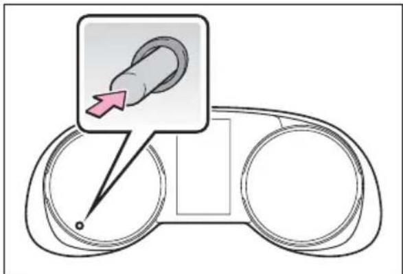
text_image
Diagram showing a hand pointing to a device with a magnified inset highlighting the finger location.Instrument panel light control
The brightness of the instrument panel lights can be adjusted by turning the dial.
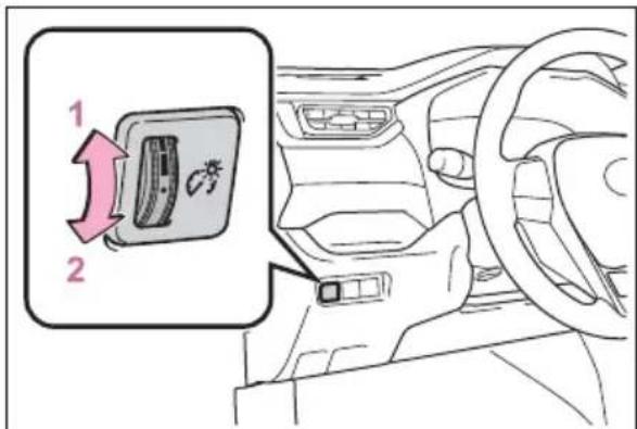
text_image
1 21 Brighter
2 Darker
■Instrument panel brightness adjustment
The instrument panel brightness levels when the tail lights are on and off can be adjusted individually. However, when the surroundings are bright (daytime, etc.), turning on the tail lights will not change the instrument panel brightness.
Adjusting the clock
The clock can be adjusted on the audio system screen.
▶ Vehicles with Audio
→P.427
▶ Vehicles with Audio Plus or Premium Audio
Refer to "NAVIGATION AND MULTIMEDIA SYSTEM OWNER'S MANUAL".
Gauges and meters (with 7-inch display)
The meters display various drive information.
Meter display
The display of the speedometer can be selected from two types, analog or digital. ( P.109)
▶ Analog speedometer
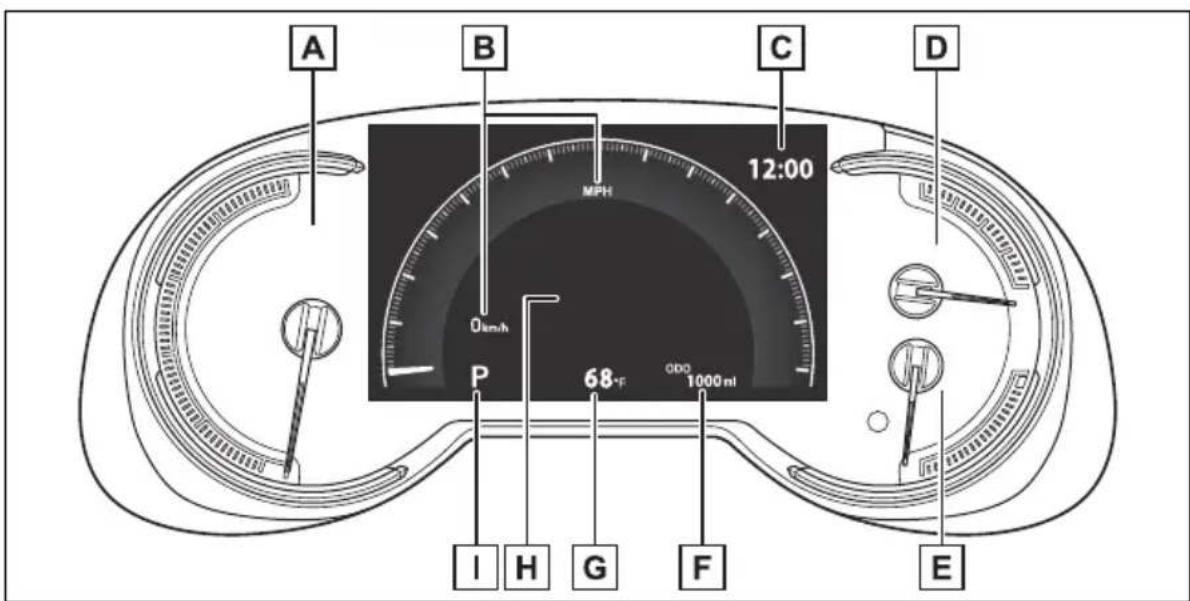
text_image
A B C D 12:00 MPH 0km/h P 68°F 0DO 1000 ml I H G F EThe units used on the meter and display may differ depending on the target region.
A Hybrid System Indicator
Displays the Hybrid System Indicator ( P.100)
B Speedometer
Displays the vehicle speed
C Clock (→P.102)
D Fuel gauge
Displays the quantity of fuel remaining in the tank
E Engine coolant temperature gauge
Displays the engine coolant temperature
F Odometer and trip meter
Odometer:
Displays the total distance that the vehicle has been driven
Trip meter:
Displays the distance the vehicle has been driven since the meter was last reset. Trip meters “A” and “B” can be used to record and display different distances independently.
G Outside temperature ( P.101)
H Multi-information display
Presents the driver with a variety of driving-related data ( P.103)
Displays warning messages if a malfunction occurs ( P.654)
I Shift position and shift range indicator
Displays the selected shift position or selected shift range ( P.219)
▶ Digital speedometer
text_image
A B C D 0 MPN 0 km/h 12:00 P 68°F ODD 1000 nl I H G F EThe units used on the meter and display may differ depending on the target region.
A Hybrid System Indicator
Displays the Hybrid System Indicator ( P.100)
B Speedometer
Displays the vehicle speed
C Clock ( P.102)
D Fuel gauge
Displays the quantity of fuel remaining in the tank
E Engine coolant temperature gauge
Displays the engine coolant temperature
F Odometer and trip meter
Odometer:
Displays the total distance that the vehicle has been driven
Trip meter:
Displays the distance the vehicle has been driven since the meter was last reset. Trip meters “A” and “B” can be used to record and display different distances independently.
G Outside temperature ( P.95)
H Multi-information display
Presents the driver with a variety of driving-related data ( P.103)
Displays warning messages if a malfunction occurs ( P.654)
I Shift position and shift range indicator
Displays the selected shift position or selected shift range ( P.219)
■The meters and display illuminate when
The power switch is in ON.
■When changing driving mode
Speedometer color is changed following the selected driving mode or when Trail Mode is turned on. (→P.366, 367)
Hybrid System Indicator
flowchart
graph TD
    A["A"] --> B["B"]
    B --> C["C"]
    C --> D["D"]
    D --> E["E"]
    E --> F["PWR"]
    F --> G["ECO"]
    G --> H["CHG"]
    H --> I["OFF"]
    style A fill:#f9f,stroke:#333
    style B fill:#f9f,stroke:#333
    style C fill:#f9f,stroke:#333
    style D fill:#f9f,stroke:#333
    style E fill:#f9f,stroke:#333
    style F fill:#f9f,stroke:#333
    style G fill:#f9f,stroke:#333
    style H fill:#f9f,stroke:#333
    style I fill:#f9f,stroke:#333
A READY OFF area
Shows that the hybrid system is not operating.
B Charge area
Shows regeneration ^* status. Regenerated energy will be used to charge the hybrid battery (traction battery).
C Hybrid Eco area
Shows that gasoline engine power
is not being used very often.
The gasoline engine will automatically stop and restart under various conditions.
D Eco area
Shows that the vehicle is being driven in an Eco-friendly manner.
By keeping the indicator needle within Eco area, more Eco-friendly driving can be achieved.
E Power area
Shows that an Eco-friendly driving range is being exceeded (during full power driving etc.)
*: When used in this manual, “regeneration” refers to the conversion of energy created by the movement of the vehicle into electrical energy.
In the following situation, the Hybrid System Indicator does not operate.
●“READY” indicator is not illuminated.
● The shift lever is in a range other than D or S.
■ Outside temperature display
● In the following situations, the correct outside temperature may not be displayed, or the display may take longer than normal to change.
- When stopped, or driving at low speeds (less than 12 mph [20 km/h])
- When the outside temperature has changed suddenly (at the entrance/exit of a garage, tunnel, etc.)
- When “--” or “E” is displayed, the system may be malfunctioning. Take your vehicle to your Toyota dealer.
●Displays the outside temperature within the range of -40^ ( -40^ ) to 122^ ( 50^ ).
- When the outside temperature is approximately 37^ F (3°C) or lower, the indicator will flash for approximately 10 seconds, then stay on.
■Liquid crystal display
→P.104
Customization
Settings (e. g. meter display) can be changed on the screen of the multi-information display. (→P.109)
WARNING
■The information display at low temperatures
Allow the interior of the vehicle to warm up before using the liquid crystal information display. At extremely low temperatures, the display monitor may respond slowly, and display changes may be delayed.
For example, there is a lag between the driver's shifting and the new shift range appearing on the display. This lag could cause the driver to downshift again, causing rapid and excessive engine braking and possibly an accident resulting in death or injury.
NOTICE
■To prevent damage to the engine and its components
The engine may be overheating if the engine coolant temperature gauge is in the red zone ("H"). In this case, immediately stop the vehicle in a safe place, and check the engine after it has cooled completely. (→P.677)
Using the "ODO TRIP" switch
Switches the items of the odometer, trip meter A and trip meter B by pressing the "ODO TRIP" switch.
When the trip meter is dis- played, pressing and holding the switch will reset the trip meter.
text_image
Diagram showing a device with a magnified inset highlighting a specific component, likely for instructional or diagnostic purposes.Instrument panel light control
The brightness of the instrument panel lights can be adjusted by turning the dial.
text_image
1 21 Brighter
2 Darker
■Instrument panel brightness adjustment
The instrument panel brightness levels when the tail lights are on and off can be adjusted individually. However, when the surroundings are bright (daytime, etc.), turning on the tail lights will not change the instrument panel brightness.
Adjusting the clock
The clock can be adjusted on the audio system screen.
▶ Vehicles with Audio
→P.427
▶ Vehicles with Audio Plus or Premium Audio
Refer to "NAVIGATION AND MULTIMEDIA SYSTEM OWNER'S MANUAL".
Multi-information display
The multi-information display is used to display fuel efficiency related information and various types of driving-related information. The multi-information display can also be used to change the display settings and other settings.
Display contents
Following information is dis- played on the multi-information display.
■Vehicles with 4.2-inch display
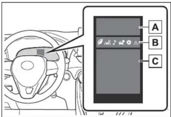
text_image
Diagram showing car interior with steering wheel, dashboard, and control panel labeled A, B, CA Driving support system information
Displays recognized signs while the RSA system (if equipped) is operating. ( P.268)
Displays an image when the following systems are operating and a
menu icon other than selected:

• LTA (Lane Tracing Assist)
(→P.258)
- Dynamic radar cruise control with full-speed range (→P.271)
B Menu icons (→P.104)
C Information display area
A variety of information can be displayed by selecting a menu icon.
Additionally, warning or suggestion/advice pop-up displays will be displayed in some situations.
■Vehicles with 7-inch display
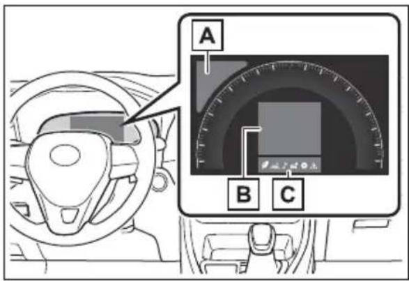
text_image
A B CA Driving support system information
Displays recognized signs while the RSA system (if equipped) is operating. (→P.268)
Displays an image when the following systems are operating and a
menu icon other than selected:

• LTA (Lane Tracing Assist) (→P.258)
- Dynamic radar cruise control with full-speed range (→P.271)
B Information display area
A variety of information can be displayed by selecting a menu icon.
Additionally, warning or suggestion/advice pop-up displays will be displayed in some situations.
C Menu icons (→P.104)
■The multi-information display is displayed when
The power switch is in ON.
■When changing driving mode
Background color of the multi-information display is changed following the selected driving mode or when Trail Mode is turned on. (→P.366, 367)
■Liquid crystal display
Small spots or light spots may appear on the display. This phenomenon is characteristic of liquid crystal displays, and there is no problem continuing to use the display.
Changing the display
The multi-information display is operated using the meter control switches.
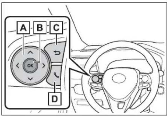
text_image
A B C OK DA Scroll the screen*/switch the display*/move the cursor
B Press: Enter/Set
Press and hold: Reset/Display customizable items
C Return to the previous screen
D Call sending/receiving and history display (if equipped) Linked with the hands-free system, sending or receiving
call is displayed. For details regarding the hands-free system, refer to P.479(vehicles with Audio) or "NAVIGATION AND MULTIMEDIA SYSTEM OWNER'S MANUAL" (vehicles with Audio Plus or Premium Audio).
*: On screens where the screen can be scrolled and the display can be switched, a scroll bar or a round icon that shows the number of registered screens is displayed.

WARNING
■Caution for use while driving
For safety, avoid operating the meter control switch while driving as much as possible, and do not look continuously at the multi-information display while driving. Stop the vehicle and operate the meter control switch. Failure to do so may cause a steering wheel operation error, resulting in an unexpected accident.
Menu icons
Information related to each icon can be displayed by selecting the icon with the meter control switches.
Some of the information may be displayed automatically depending on the situation.
| Icon Display | |
 | Driving information display (→P.105) |
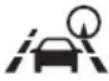 | Driving support system information display (→P.107) |
| [YASK] | Audio system-linked display (if equipped) (→P.107) |
 | Vehicle information display (→P.108) |
| [2CKA] | Settings display (→P.109) |
 | Warning message display (→P.112) |
Driving information dis- play
Select to display fuel consumption data in various forms.
■Speedometer display/Distance to empty (4.2-inch display)
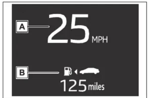
text_image
A—25 MPH B—125 milesA Speedometer display
Displays the vehicle speed.
B Distance to empty
Displays the driving range with
remaining fuel. ( P.107)
Fuel Economy
Following information is displayed.
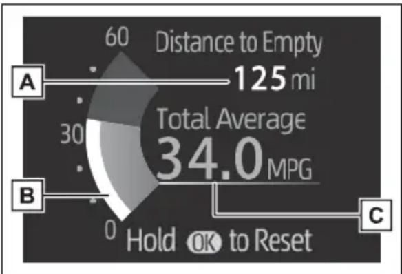
gauge
| Category | Value | |---|---| | Distance to Empty | 125 mi | | Total Average | 34.0 MPG | | Hold OK to Reset | 0 | | C | 0 |A Distance to empty
Displays the driving range with remaining fuel. ( P.107)
B Current fuel economy
Displays the instantaneous current fuel Economy.
C Average fuel economy
Displays the average fuel economy since the function was reset or the average fuel economy after starting or refueling. ^*1, 2, 3
The average fuel economy selected by “Fuel Economy” on the screen is displayed. (→P.109)
*1: Use the displayed fuel consumption as a reference only.
*2: Average fuel economy since the function was reset can be reset by pressing and holding OK
*3: Average fuel economy after starting is reset each time the hybrid system stops.
■ ECO Accelerator Guidance/“Eco Score”
Displays a reference operation
range for using the accelerator pedal according to driving conditions, and a score result that evaluates the current driving status.
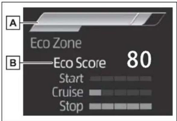
text_image
A Eco Zone B Eco Score 80 Start Cruise StopA ECO Accelerator Guidance
B "Eco Score"
ECO Accelerator Guidance
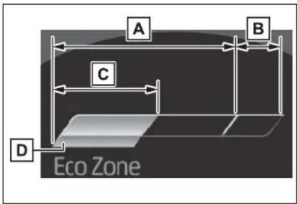
text_image
A B C D Eco ZoneA ECO area
Shows that the vehicle is being driven in an Eco-friendly manner.
B Power area
Shows that an Eco-friendly driving range is being exceeded (during full power driving etc.).
C Current acceleration
D Reference operation range
A zone is displayed in blue under the Eco area which can be used as a reference operation range for using the accelerator pedal according to driving conditions such as starting off and cruising.
The ECO Accelerator Guidance display changes according to the driving status, such as when starting off or cruising.
It is easier to drive in an Eco-friendly manner by driving according to the display showing the accelerator pedal operations and staying within the reference operation range.
"Eco Score"
The driving status for the following 3 situations are evaluated in 5 levels: Smooth start-off acceleration (“Start”), driving without sudden acceleration (“Cruise”) and smooth stopping (“Stop”).
Each time the vehicle is stopped, a score result is displayed out of a perfect score of 100 points.
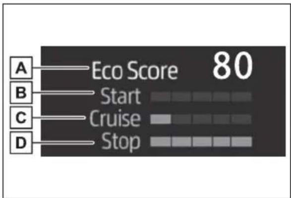
text_image
A Eco Score 80 B Start C Cruise D StopA Score result
B "Start"
C "Cruise"
D "Stop"
How to read the bar display:
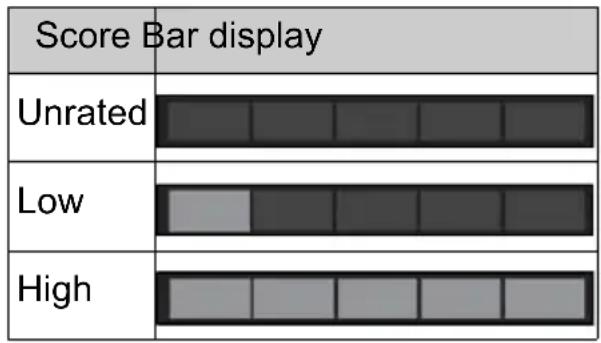
bar
| Category | Bar Value | |---|---| | Unrated | 0 | | Low | 0 | | High | 0 |After starting off, “Eco Score” display does not start until the vehicle speed exceeds approximately 12 mph (20 km/h).
The “Eco Score” is reset each time the vehicle starts off to start a new evaluation.
When the hybrid system stops, the current total score result is displayed.*
*: The score result is displayed only when “Eco Score” is selected for “Trip Summary”. (→P.109)
Distance to empty
● This distance is computed based on your average fuel consumption. As a result, the actual distance that can be driven may differ from that displayed.
- When only a small amount of fuel is added to the tank, the display may not be updated. When refueling, turn the power switch to OFF. If the vehicle is refueled without turning the power switch to OFF, the display may not be updated.
- When “Refuel” is displayed, the remaining fuel amount is low and the distance that can be driven with the remaining fuel cannot be calculated.
Refuel immediately.
■ ECO Accelerator Guidance/“Eco Score” will not operate when
The ECO Accelerator Guidance/“Eco Score” will not operate in the following situations:
●The Hybrid System Indicator is not operating.
●The vehicle is being driven using the dynamic radar cruise control with full-speed range.
Driving support system information display
■Driving support system information display
Select to display the operational status of the following systems:
● LTA (Lane Tracing Assist) ( P.258)
● Dynamic radar cruise control with full-speed range ( P.271)
■Navigation system-linked display (if equipped)
Select to display the following navigation system-linked information.
- Route guidance
- Compass display
Audio system-linked display (if equipped)
Select to enable selection of an audio source or track on the display.
Vehicle information display
■Drive information
2 items that are selected using the “Drive Info Items” setting (average speed, distance and total time) can be displayed vertically.
The displayed information changes according to the “Drive Info Type” setting (since the system was started or between resets). ( P.109)
Use the displayed information as a reference only.
Following items will be displayed.
- "Trip"
- "Average Speed": Displays the average vehicle speed since hybrid system start*
- "Distance": Displays the distance driven since hybrid system start*
- "Total Time": Displays the elapsed time since hybrid system start*
*: These items are reset each time the hybrid system stops.
• "Total"
- "Average Speed": Displays the average vehicle speed since the display was reset*
- "Distance": Displays the distance driven since the display was reset*
- “Total Time”: Displays the elapsed time since the display
was reset ^*
*: To reset, display the desired item and press and hold OK
■Energy monitor
→P.113
■AWD system display
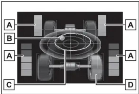
text_image
A B A C A A DA Torque distribution display
Displays the drive status of each wheel in 6 steps from 0 to 5.
B G-force display*
Displays the size and direction of the G-force applied to the vehicle via changes to the position of the ball on the display.
C Maximum G-force course*
This item is linked with the G-force display and the course of the past movement of the ball is displayed.
Press and hold to reset the record.
D Wheel spin display
When a tire is spinning, its icon on the display changes its color and blinks.
*: This item is displayed only when driving mode is set to sport mode.
Settings display
Vehicle settings and the content displayed on the screen can be changed by using the meter control switches.
■Setting procedure
1 Operate or of the meter control switches and select
2 Operate or of the meter control switches and select the desired item.
- If the function is turned on and off or the volume, etc. is changed on the setting screen, the setting is changed each time is pressed.
- For functions that allow operation contents, display contents, etc., of function to be selected, the setting screen is displayed by pressing and holding OK When the setting screen is displayed, select the setting or desired value (time, etc.) with OK
3 After changing the settings, press of the meter control switches.
■ LTA (Lane Tracing Assist) (→P.258)
Select to set up the following items.
● “Lane Center”
Select to enable/disable the lane
centering function.
- “Steering Assist”
Select to enable/disable steering wheel assistance.
- “Sensitivity”
Select to set the lane departure alert sensitivity.
- "Sway Warning"
Select to enable/disable the vehicle sway warning.
- “Sway Sensitivity”
Select to set the vehicle sway warning sensitivity.
■ PCS (Pre-Collision System) (→P.250)
Select to set up the following items.
- PCS on/off
Select to enable/disable the pre-collision system.
- “Sensitivity”
Select to change the pre-collision warning timing.
■ BSM (Blind Spot Monitor) (if equipped) (→P.282)
Select to set up the following items.
● BSM (Blind Spot Monitor) on/off
Select to enable/disable the BSM system.
● "Brightness"
Select to switch the brightness of the outside rear view mirror indicators. ( P.283)
- "Sensitivity"
Select to change the alert timing for an approaching vehicle.
■ (Intuitive parking assist) (if equipped) (→P.291)
Select to set up the following items.
● Intuitive parking assist on/off
Select to enable/disable the Intuitive parking assist.
- "Volume"
Select to set the volume of the buzzer which sounds when the Intuitive parking assist is operated.
■RCTA (Rear Cross Traffic Alert) (if equipped) (→P.282)
● RCTA (Rear Cross Traffic Alert) on/off
Select to enable/disable the RCTA system.
- "Volume"
Select to change the RCTA buzzer volume.
■ PKSB (Parking Support Brake System) (if equipped) (→P.298)
Select to enable/disable the Parking Support Brake function.
■ RSA (Road Sign Assist) (if equipped) (→P.268)
Select to set up the following items.
● Road Sign Assist on/off
Select to enable/disable the RSA system.
- “Notification method”
Select to change each notification method used to notify the driver when the system recognizes excess speed and Do Not Enter sign.
● "Notification Level"
Select to change each notification level used to notify the driver when the system recognizes a speed limit sign.
■ Vehicle Settings
● PBD (Power Back Door) (if equipped) (→P.137)
Select to set up the following items.
- System settings
Select to enable/disable the power back door system.
- “Hands Free”*
Select to enable/disable the Hands Free Power Back Door.
- "Opening Adjustment"
Select the open position when power back door is fully open.
- “Volume”
Select to set the volume of the buzzer which sounds when the power back door system operates.
*: Vehicles with Hands Free Power Back Door
- “TPWS” (Tire Pressure Warning System) (if equipped) (→P.593)
- "Set Pressure"
Select to initialize the tire pressure warning system.
- "Change Wheel" (except for models made in Japan* without tire inflation pressure display function)
Select to register the ID codes of the tire pressure sensors to the tire pressure warning system.
- “Change Wheel” (for models made in Japan* without tire inflation pressure display function)
Select to change the tire pressure warning system sensor ID code set. To enable this function, a second set of tire pressure warning system sensor ID codes must be registered by a Toyota dealer. For information regarding changing the registered ID code set, contact your Toyota dealer.
*: The country of production is written on the Certification Regulation Label. (→P.684)
● “Scheduled Maintenance” ( P.573)
Select to reset the scheduled maintenance information (message indicating maintenance is required and distance until the next maintenance) after all maintenance is performed.
Settings
- "Language"
Select to change the language on the multi-information display.
- "Units"
Select to change the units of measure displayed.
● “Meter Type” (7-inch display)
Select to change the speedometer display.
• E(EV indicator) (→P.73)
Select to enable/disable the EV indicator.
● (Driving information display settings)
Select to set up the following items.
- "Hybrid System"
Select to enable/disable the ECO Accelerator Guidance ( P.105).
- "Fuel Economy"
Select to change the display on Fuel Economy ( P.105).
● ♪ (Audio settings) (if equipped)
Select to enable/disable screen.
● Vehicle information display settings)
- "Display Contents"
Select to set up the following items.
"Energy monitor":
Select to enable/disable the Energy monitor ( P.113)
"AWD":
Select to enable/disable the AWD system display ( P.108).
- "Drive Info Type"
Select to change the drive information type display between trip and total. ( P.108).
- "Drive Info Items"
Select to set the items on the upper
and lower side of the drive information screen from three items, average speed, distance and total time.
- “Trip Summary”
Select to set the items displayed when the power switch is turned off.
- "Pop-Up Display"
Select to enable/disable the following pop-up displays, which may appear in some situations.
- Intersection guidance display of the navigation system-linked system (if equipped)
- Incoming call display of the hands-free phone system (if equipped)
• Audio operation (if equipped)
• Volume operation (if equipped)
• Voice control (if equipped)
● "MID OFF"
A blank screen is displayed.
- “Default Settings”
Select to reset the meter display settings.
■ Suspension of the settings display
● In the following situations, operation of the settings display will be temporarily suspended.
- When a warning message appears on the multi-information display
- When the vehicle begins to move
● Settings for functions not equipped to the vehicle are not displayed.
- When a function is turned off, the related settings for that function are not selectable.

WARNING
■ Cautions during setting up the display
As the hybrid system needs to be operating during setting up the display, ensure that the vehicle is parked in a place with adequate ventilation. In a closed area such as a garage, exhaust gases including harmful carbon monoxide (CO) may collect and enter the vehicle. This may lead to death or a serious health hazard.

NOTICE
■During setting up the display
To prevent 12-volt battery discharge, ensure that the hybrid system is operating while setting up the display features.
Warning message display
Select to display warning messages and measures to be taken if a malfunction is detected. (→P.654)
Suggestion function
Displays suggestions to the driver in the following situations. To select a response to a displayed suggestion, use the meter control switches.
■Suggestion to turn on the headlights
If the headlight switch is in other than ☐, and the vehicle speed is 3 mph (5 km/h) or higher for a certain amount of time when the surroundings are
dark, a suggestion message will be displayed.
■Suggestion to turn off the headlights
If the headlights are left on for a certain amount of time after the power switch has been turned off, a suggestion message will be displayed.
When the headlight switch is in the AUTO position: The message asking if you wish to turn the headlights off is displayed. To turn the headlights off, select "Yes".
If the driver's door is opened after the power switch is turned off, this suggestion message will not be displayed.
Customization
The suggestion function can be turned on/off. (Customizable features: →P.708)
Energy monitor/con- sumption screen
You can view the status of your vehicle on the multi-information display and the audio system screen*.
*: For navigation system or multi-media system
System components
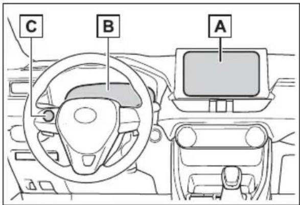
text_image
C B AA Audio system screen
B Multi-information display
C Meter control switches (→P.101)
Energy monitor
The energy monitor can be used to check the vehicle drive status, hybrid system operation status and energy regeneration status.
■Display
▶ Multi-information display
Press or of the meter control switches on the steering
wheel and select, and
then press or to select the energy monitor display.
▶ Audio or Audio Plus (vehicles without Data Communication Module)
1 Press the "MENU" button.
2 Select "Info" on the "Menu" screen.
If a screen other than "Energy monitor" is displayed, select "Energy".
▶ Audio or Audio Plus (vehicles with Data Communication Module)/Premium Audio
1 Press the "MENU" button.
2 Select "Info" on the "Menu" screen.
3 Select "ECO" on the "Information" screen.
If a screen other than "Energy monitor" is displayed, select "Energy".
■Reading the display
The arrows will appear in accordance with the energy flow.
When there is no energy flow, arrows will not be displayed.
The color of the arrows will change as follows
Green: When the hybrid battery (traction battery) is regenerated or charged.
Yellow: When the hybrid battery (traction battery) is in use.
Red: When the gasoline engine is in use.
▶ Multi-information display
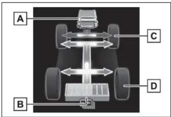
text_image
A C D BThe image shows all the arrows as an example. The actual display will vary depending on conditions.
A Gasoline engine
B Hybrid battery (traction battery)
C Front tire
D Rear tire*
*: For FF vehicles, the arrows to D are not displayed.
▶ Audio system screen
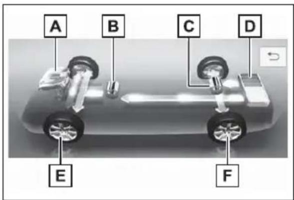
text_image
A B C D E FThe image shows all the arrows as an example. The actual display will vary depending on conditions.
A Gasoline engine
B Front electric motor (traction motor)
C Hybrid battery (traction battery)
D Rear electric motor (traction motor)
E Front tire
F Rear tire*
*: For FF vehicles, the arrows to F are not displayed.
Audio system screen ("Home" screen)
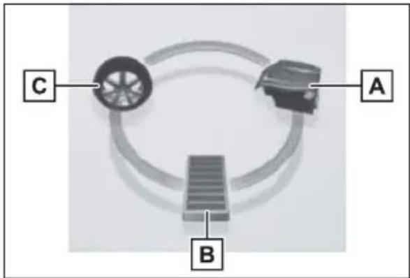
flowchart
graph TD
    A["A"] --> B["B"]
    B --> C["C"]
    C --> A
The image shows all the arrows as an example. The actual display will vary depending on conditions.
A Gasoline engine
B Hybrid battery (traction battery)
C Tire
■ Hybrid battery (traction battery) status
The display changes in 8 levels according to the remaining charge amount of the hybrid battery (traction battery).
●The figure shows the multi-information display as an example for explanation.
●These images are examples only, and may vary slightly from actual conditions.
natural_image
Diagram showing two rectangular containers labeled A and B with bidirectional arrows indicating movement or flow (no text or symbols beyond labels)A Low
B High
■Remaining charge amount warning of hybrid battery (traction battery)
●The buzzer sounds intermittently when the hybrid battery (traction battery) remains without charging while the shift lever is in N, or the remaining charge amount drops below a certain level. If the remaining charge amount drops further, the buzzer sounds continuously.
- When a warning message is shown on the multi-information display and the buzzer sounds, follow the instructions displayed on the screen to perform trouble-shooting.
Consumption
■Display
▶ Audio or Audio Plus (vehicles without Data Communication Module)
1 Press the "MENU" button.
2 Select "Info" on the "Menu" screen.
3 Select "Trip information" or "History".
▶ Audio or Audio Plus (vehicles with Data Communication Module)/Premium Audio
1 Press the "MENU" button.
2 Select "Info" on the "Menu" screen.
3 Select "ECO" on the "Information" screen.
4 Select "Trip information" or "History".
■Trip information
If a screen other than “Trip information” is displayed, select “Trip information”.
The image is an example only, and may vary slightly from actual conditions.
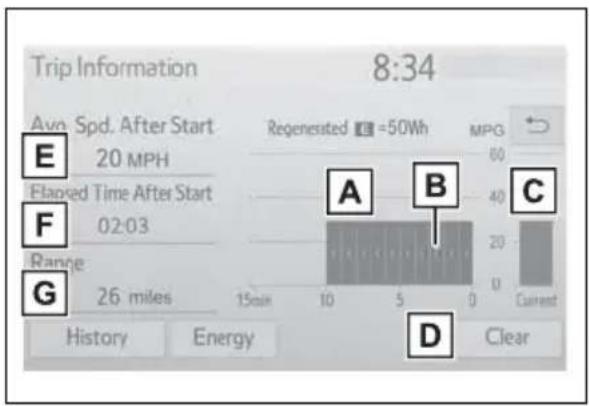
text_image
Trip Information 8:34 Avo Spd. After Start Regenerated =50Wh MPG 20 MPH Flanked Time After Start 02:03 Range 26 miles A B C 15min 10 5 0 Current History Energy ClearA Fuel consumption in the past 15 minutes
B Regenerated energy in the past 15 minutes
One symbol indicates 50 Wh. Up to 5 symbols are shown.
C Current fuel consumption
D Resetting the consumption data
E Average vehicle speed since the hybrid system was
started
F Elapsed time since the hybrid system was started
G Cruising range ( P.117)
Average fuel consumption for the past 15 minutes is divided by color into past averages and averages attained since the power switch was last turned to ON. Use the displayed average fuel consumption as a reference.
History
If a screen other than "History" is displayed, select "History".
The image is an example only, and may vary slightly from actual conditions.
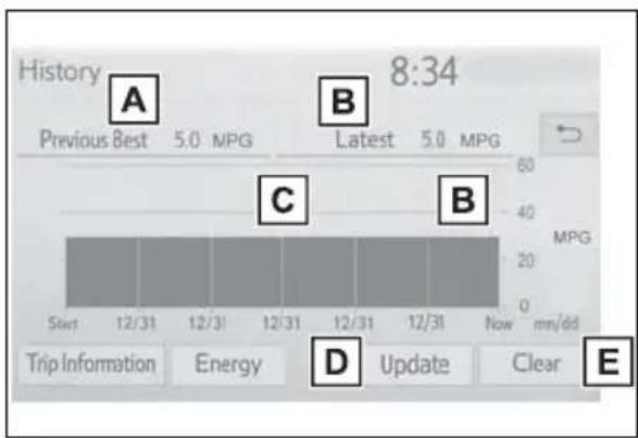
text_image
History 8:34 Previous Best 5.0 MPG Latest 5.0 MPG Start 12/31 12/31 12/31 12/31 12/31 New mn/dd Trip Information Energy D Update Clear E A B C B MPGA Best recorded fuel consumption
B Latest fuel consumption
C Previous fuel consumption record
• Audio and Audio Plus:
Displays the daily average fuel consumption. (Instead of the date, "Trip 1" through "Trip 5" will be displayed.)
- Premium Audio:
Displays the daily average fuel consumption.
D Updating the latest fuel consumption data
E Resetting the history data
The average fuel consumption history is divided by color into past averages and the average fuel consumption since the last time updated. Use the displayed average fuel consumption as a reference.
■ Updating the history data
Update the latest fuel consumption by selecting “Update” to measure the current fuel consumption again.
■ Resetting the data
The fuel consumption data can be deleted by selecting "Clear".
Cruising range
Displays the estimated maximum distance that can be driven with the quantity of fuel remaining.
This distance is computed based on your average fuel consumption. As a result, the actual distance that can be driven may differ from that displayed.
3
3-1. Key information
Keys 120
3-2. Opening, closing and locking the doors
Side doors.... 127
Back door.... 133
Smart key system ..... 147
3-3. Adjusting the seats
Front seats 153
Rear seats.... 154
Driving position memory 156
Head restraints...... 159
3-4. Adjusting the steering wheel and mirrors
Steering wheel ...... 162
Inside rear view mirror 163
Digital Rear-view Mirror165
Outside rear view mirrors 174
3-5. Opening, closing the windows and moon roof
Power windows ..... 176
Moon roof...... 179
Panoramic moon roof.. 182
Keys
Key types
The following keys are provided with the vehicle.
▶ Vehicles without smart key system
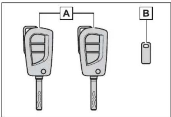
flowchart
graph TD
    A["Car Locker A"] --> B["Mobile Phone"]
    A --> C["Car Locker B"]
A Master keys
Operating the wireless remote control function ( P.122)
B Key number plate
▶ Vehicles with smart key system
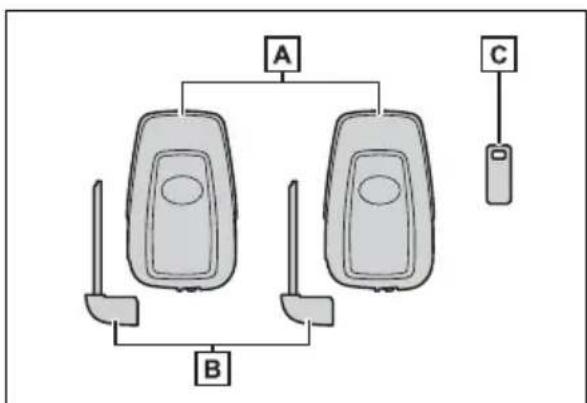
flowchart
graph TD
    A["A"] --> B["B"]
    A --> C["C"]
A Electronic keys
- Operating the smart key system (→P.147)
- Operating the wireless remote control function (→P.122)
B Mechanical keys
C Key number plate
■When riding in an aircraft
When bringing a key with wireless remote control function onto an aircraft, make sure you do not press any buttons on the key while inside the aircraft cabin. If you are carrying the key in your bag etc., ensure that the buttons are not likely to be pressed accidentally. Pressing a button may cause the key to emit radio waves that could interfere with the operation of the aircraft.
■Key battery depletion
▶ Vehicles without smart key system
●The standard battery life is 1 to 2 years.
●The battery will become depleted even if the wireless key is not used. The following symptoms indicate that the wireless key battery may be depleted. Replace the battery when necessary.
(→P.618)
- The wireless remote control does not operate.
• The detection area becomes smaller.
▶ Vehicles with smart key system
●The standard battery life is 1 to 2 years.
- If the battery becomes low, an alarm will sound in the cabin and a message will be displayed on the multi-information display when the hybrid system stops.
●To reduce key battery depletion when the electronic key is to not be used for long periods of time, set the electronic key to the battery-saving mode. (→P.148)
As the electronic key always receives radio waves, the battery will become depleted even if the electronic key is not used. The following symptoms indicate that the electronic key battery may be depleted. Replace the battery
when necessary.
- The smart key system or the wireless remote control does not operate.
- The detection area becomes smaller.
- The LED indicator on the key surface does not turn on.
You can replace the battery by yourself ( P.618). However, as there is a danger that the electronic key may be damaged, it is recommended that replacement is carried out by your Toyota dealer.
● To avoid serious deterioration, do not leave the electronic key within 3 ft. (1 m) of the following electrical appliances that produce a magnetic field:
• TVs
- Personal computers
- Cellular phones, cordless phones and battery chargers
- Table lamps
- Induction cookers
If a message regarding the state of the electronic key or power switch mode, etc. is shown (vehicles with smart key system)
To prevent trapping the electronic key inside the vehicle, leaving the vehicle carrying the electronic key on your person without turning the power switch to OFF or other passengers from unintentionally taking the key out of the vehicle, etc., a message that prompts the user to confirm the state of the electronic key or power switch mode may be shown on the multi-information display. In those cases, follow the instructions on the display immediately.
If "Key Battery Low Replace Key Battery" is displayed on the multi-information display (vehicles with smart key system)
The electronic key has a low battery. Replace the electronic key battery. (→P.618)
■Replacing the battery
→P.618
■ Confirmation of the registered key number
The number of keys already registered to the vehicle can be confirmed. Ask your Toyota dealer for details.
If “A New Key has been Registered Contact Your Dealer for Details” is displayed on the multi-information display (vehicles with smart key system)
This message will be displayed each time the driver's door is opened when the doors are unlocked from the outside for approximately 10 days after a new electronic key has been registered. If this message is displayed but you have not had a new electronic key registered, ask your Toyota dealer to check if an unknown electronic key (other than those in your possession) has been registered.

NOTICE
■To prevent key damage
- Do not drop the keys, subject them to strong shocks or bend them.
- Do not expose the keys to high temperatures for long periods of time.
- Do not get the keys wet or wash them in an ultrasonic washer, etc.
- Do not attach metallic or magnetic materials to the keys or place the keys close to such materials.
- Do not disassemble the keys.

NOTICE
- Do not attach a sticker or anything else to the surface of the keys.
- Do not place the keys near objects that produce magnetic fields, such as TVs, audio systems and induction cookers.
- Do not place the keys near medical electrical equipment such as low-frequency therapy equipment or microwave therapy equipment, and do not receive medical attention with the keys on your person.
■Carrying the electronic key on your person (vehicles with smart key system)
Carry the electronic key 3.9 in. (10 cm) or more away from electric appliances that are turned on. Radio waves emitted from electric appliances within 3.9 in. (10 cm) of the electronic key may interfere with the key, causing the key to not function properly.
In case of a smart key system malfunction or other key-related problems (vehicles with smart key system)
$$ \rightarrow \mathrm{P}. 6 7 0 $$
■When an electronic key is lost (vehicles with smart key system)
$$ \rightarrow \mathrm{P}. 6 6 8 $$
Wireless remote control
The keys are equipped with the following wireless remote control:
▶ Vehicles without smart key system
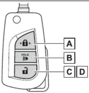
text_image
A B C DA Locks all the doors ( P.127)
B Sounds the alarm ( P.123)
C Unlocks all the doors ( P.127)
D Opens the side windows ^* (→P.127)
*: This setting must be customized at your Toyota dealer.
▶ Vehicles with smart key system
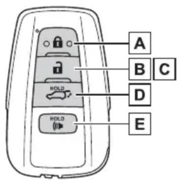
text_image
A B C D E HOLD HOLDA Locks all the doors ( P.127)
B Unlocks all the doors ( P.127)
C Opens the side windows ^1 and the moon roof ^1,2 or panoramic moon roof ^*1,2 ( P.127)
D Opens and closes the power back door ^*2 (→P.137)
E Sounds the alarm ( P.123)
*1: These settings must be customized at your Toyota dealer.
*2:If equipped
■Theft deterrent panic mode
▶ Vehicles without smart key system
When (pressed for longer than about 1 second, an alarm will sound intermittently and the vehicle lights will flash to deter any person from trying to break into or damage your vehicle.
To stop the alarm, press any button on the key.
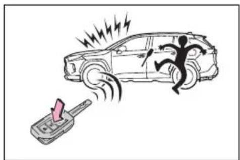
natural_image
Illustration of a person running away from a car with lightning bolts and a mobile phone emitting smoke (no text or symbols)▶ Vehicles with smart key system
When (\$) pressed for longer than about 1 second, an alarm will sound intermittently and the vehicle lights will flash to deter any person from trying to break into or damage your vehicle.
To stop the alarm, press any button on the electronic key.
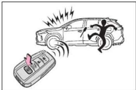
natural_image
Illustration of a car being hit by a moving phone, with lightning and motion lines indicating speed (no text or symbols)■ Conditions affecting operation
▶ Vehicles without smart key system
The wireless remote control function may not operate normally in the following situations.
- When the wireless key battery is depleted
●Near a TV tower, electric power plant, gas station, radio station, large display, airport or other facility that generates strong radio waves or electrical noise - When carrying a portable radio, cellular phone or other wireless communication device
- When the wireless key is in contact with, or is covered by a metallic object
- When other wireless key (that emits radio waves) is being used nearby
- If window tint with a metallic content or metallic objects are attached to the rear window
▶ Vehicles with smart key system →P.148
■Certification for wireless remote control
FCC ID:HYQ23ABE
FCC ID:HYQ12BFW
NOTE:
This device complies with part 15 of the FCC Rules. Operation is subject to the following two conditions: (1) This device may not cause harmful interference, and (2) this device must accept any interference received, including interference that may cause undesired operation.
FCC WARNING:
Changes or modifications not expressly approved by the party responsible for compliance could void the user's authority to operate the equipment.
The FCC ID is affixed inside the equipment. You can find the ID when replacing the battery.
TPM Sensor Model: 335098 FCC ID: GQ4-72T IC: 1470A-53T
RKE Transmitter Model: 336600 FCC ID: GQ4-73T IC: 1470A-54T
Integrated Receiver Model: 337136 FCC ID: GQ4-50R CAN RSS-GEN/CNR-GEN
MADE IN U.S.A.
This device complies with Part 15 of the FCC Rules and with Canada license-exempt RSS standard(s). Operation is subject to the following two conditions:
(1) This device may not cause harmful interference, and (2) This device must accept any interference received, including interference that may cause undesired operation.
Le present appareil est conforme aux CNR d'Industrie Canada applicable aux appareils radio exempts de licence.
WARNING: Changes or modifications not expressly approved by BCS Access Systems US LLC could void the user's authority to operate the equipment.
The term "IC:" before the radio certification
Using the master key (vehicles without smart key system)
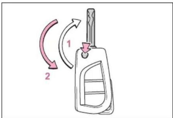
text_image
Diagram showing a car key with two curved arrows labeled 1 and 2 indicating rotational or directional movement.1 Releasing
To release the key, press the button.
2 Folding
To stow the key back in its case, push the key back to the stowed position while pressing the button.
Using the mechanical key (vehicles with smart key system)
To take out the mechanical key, slide the release lever A and take the key out.
The mechanical key can only be inserted in one direction, as the key only has grooves on one side. If the key cannot be inserted in a lock cylinder, turn it over and re-attempt to insert it.
After using the mechanical key, store it in the electronic key. Carry the mechanical key together with the electronic key. If the electronic key battery is depleted or the entry function does not operate properly, you will need the mechanical key. (→P.670)
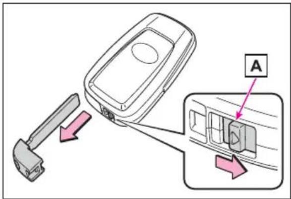
text_image
Diagram showing a car door panel being inserted into a control panel, with labeled component A and directional arrows indicating movement.■If you lose your keys
→P.668
If a wrong key is used
The key cylinder rotates freely to isolate inside mechanism.
Side doors
The vehicle can be locked and unlocked using the entry function, wireless remote control, key or door lock switch.
Unlocking and locking the doors from the outside
■Using the entry function (vehicles with smart key system)
Carry the electronic key to enable this function.
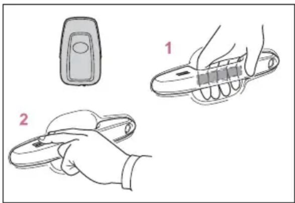
text_image
Illustration showing two-step steps of a mobile phone control device: one with a remote control and the other with a hand holding a key.1 Grip the driver's door handle to unlock the door. Holding the driver's door handle for approximately 2 seconds unlocks all the doors. Grip the front passenger's door handle or rear door handle (some models) to unlock all the doors*.
Make sure to touch the sensor on the back of the handle.
The doors cannot be unlocked for 3 seconds after the doors are locked.
*: The door unlock settings can be
changed. ( P.128)
2 Touch the lock sensor (the indentation on the upper part of the door handle) to lock the doors.
Check that the door is securely locked.
■ Using the wireless remote control
▶ Vehicles without smart key system
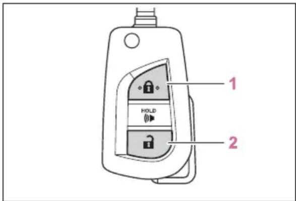
text_image
1 HOLD 21 Locks all the doors
Check that the door is securely locked.
2 Unlocks all the doors
Pressing the button unlocks the driver's door. Pressing the button again within 5 seconds unlocks the other doors.
Press and hold to open the side windows.*
*: This setting must be customized at your Toyota dealer.
▶ Vehicles with smart key system
text_image
1 2 HOLD HOLD1 Locks all the doors
Check that the door is securely locked.
2 Unlocks all the doors
Pressing the button unlocks the driver's door. Pressing the button again within 5 seconds unlocks the other doors.
Press and hold to open the side windows and moon roof (if equipped) or panoramic moon roof (if equipped).*
*: This setting must be customized at your Toyota dealer.
■Using the key
▶ Vehicles without smart key system
text_image
Diagram illustrating car safety instructions with labeled steps 1 and 2 showing a vehicle and steering wheel assembly.1 Locks all the doors
Turn and hold to close the side windows.*
2 Unlocks all the doors
Turning the key unlocks the driver's door. Turning the key again within 5 seconds unlocks the other doors.
Turn and hold to open the side windows.*
*: These settings must be customized at your Toyota dealer.
▶ Vehicles with smart key system
The doors can also be locked and unlocked with the mechanical key. (→P.670)
■ Switching the door unlock function (vehicles with smart key system)
It is possible to set which doors the entry function unlocks using the wireless remote control.
1 Turn the power switch to OFF.
2 When the indicator light on the key surface is not on, press and
hold , or for approximately 5 seconds while pressing and holding .
The setting changes each time an operation is performed, as shown below. (When changing the setting continuously, release the buttons, wait for at least 5 seconds, and repeat step 2.)
| Multi-information display/Beep | Unlocking function |
 Exterior: Beeps 3 timesInterior: Pings once Exterior: Beeps 3 timesInterior: Pings once | Holding the driver's door handle unlocks only the driver's door. |
| Holding the passenger's door handle or pressing the back door opener switch unlocks all the doors. | |
 Exterior: Beeps twiceInterior: Pings once Exterior: Beeps twiceInterior: Pings once | Holding a door handle or pressing the back door opener switch unlocks all the doors. |
Vehicles with alarm: To prevent unintended triggering of the alarm, unlock the doors using the wireless remote control and open and close a door once after the settings have been changed. (If a door is not opened within 60 seconds after
is pressed, the doors will be locked again and the alarm will automatically be set.) In a case that the alarm is triggered, immediately stop the alarm. (→P.84)
Operation signals
Doors: A buzzer sounds and the emergency flashers flash to indicate that the doors have been locked/unlocked using the entry function or wireless remote control. (Locked: Once; Unlocked: Twice)
Side windows and moon roof (if equipped) or panoramic moon roof (if equipped): A buzzer sounds to
indicate that the side windows and moon roof or panoramic moon roof are operating using the wireless remote control.
■Security feature
▶ Vehicles without smart key system If a door is not opened within approximately 60 seconds after the vehicle is unlocked using the wireless remote control, the security feature automatically locks the vehicle again.
▶ Vehicles with smart key system If a door is not opened within approximately 60 seconds after the vehicle is unlocked using the entry function or wireless remote control, the security feature automatically locks the vehicle again. (However, depending on the location of the electronic key, the key may be detected as being in the vehicle. In this case, vehicle may be unlocked.)
■When the door cannot be locked by the lock sensor on the upper part of the door handle (vehicles with smart key system)
If the door will not lock even when the topside sensor area is touched, try touching both the topside and underside sensor areas at the same time.
When gloves are being worn, remove the gloves.
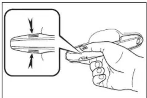
natural_image
Illustration of a hand holding a tool with a magnified inset showing a curved object (no text or symbols)■Door lock buzzer (vehicles with smart key system)
If an attempt to lock the doors using the smart key system is made when a door other than the door you are locking is open, a buzzer sounds
continuously for 5 seconds. Fully close all the doors, and lock the vehicle once more.
■Setting the alarm (if equipped)
Locking the doors will set the alarm system. ( P.84)
■Conditions affecting the operation of the smart key system or wireless remote control
▶ Vehicles without smart key system →P.123
▶ Vehicles with smart key system →P.148
If the smart key system (if equipped) or the wireless remote control does not operate properly
● Vehicles with smart key system: Use the mechanical key to lock and unlock the doors. (→P.670)
- Replace the key battery with a new one if it is depleted. (→P.618)
■If the 12-volt battery is discharged
The doors cannot be locked and unlocked using the smart key system (if equipped) or wireless remote control. Lock or unlock the doors using the key (vehicles without smart key system) or mechanical key (vehicles with smart key system). (→P.128, 670)
Customization
Settings (e.g. unlocking function using a key) can be changed. (Customizable features: →P.709)

WARNING
■To prevent an accident
Observe the following precautions while driving the vehicle.
Failure to do so may result in a door opening and an occupant could be thrown out of the vehicle, resulting in death or serious injury.
- Ensure that all doors are properly closed and locked.
- Do not pull the inside handle of the doors while driving. Be especially careful for the front doors, as the doors may be opened even if the inside lock buttons are in locked position.
- Set the rear door child-protector locks when children are seated in the rear seats.
■When opening or closing a door
Check the surroundings of the vehicle such as whether the vehicle is on an incline, whether there is enough space for a door to open and whether a strong wind is blowing. When opening or closing the door, hold the door handle tightly to prepare for any unpredictable movement.

WARNING
When using the wireless remote control, key or mechanical key and operating the power windows, moon roof (if equipped) or panoramic moon roof (if equipped)
Operate the power window, moon roof or panoramic moon roof after checking to make sure that there is no possibility of any passenger having any of their body parts caught in the side window, moon roof or panoramic moon roof. Also, do not allow children to operate the wireless remote control, key or mechanical key. It is possible for children and other passengers to get caught in the side window, moon roof or panoramic moon roof.
Unlocking and locking the doors from the inside
■Using the door lock switch
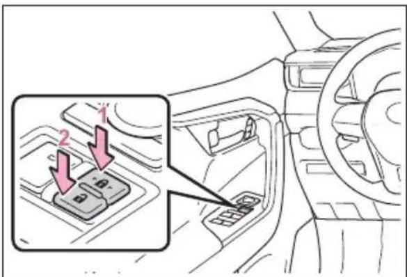
text_image
Diagram showing car interior with labeled buttons and directional arrows, highlighting a specific component in the first panel.1 Locks all the doors
2 Unlocks all the doors
■ Using the inside lock buttons
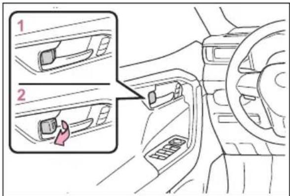
text_image
Diagram showing car interior control panel with two zoomed-in views labeled 1 and 2, highlighting a hand gesture.The front doors can be opened by pulling the inside handle even if the lock buttons are in the lock position.
■Locking the front doors from the outside without a key
1 Move the inside lock button to the lock position.
2 Close the door.
▶ Vehicles without smart key system
The door cannot be locked if the key is in the power switch.
▶ Vehicles with smart key system
The door cannot be locked if the power switch is in ACC or ON, or the electronic key is left inside the vehicle.
Depending on the position of the electronic key, the key may not be detected correctly and the door may be locked.
■Open door warning buzzer
If the vehicle speed reaches 3 mph (5 km/h), a buzzer sounds to indicate that the door(s) or the hood is not fully closed.
The open door(s) or hood is displayed on the multi-information display.
When all the doors are locked with the entry function (vehicles with smart key system), wireless remote control or key
●The doors cannot be unlocked with the door lock switch.
●The door lock switch can be reset by unlocking all the doors with the entry function (vehicles with smart key system), wireless remote control or key.
Rear door child-protector lock
The door cannot be opened from inside the vehicle when the lock is set.
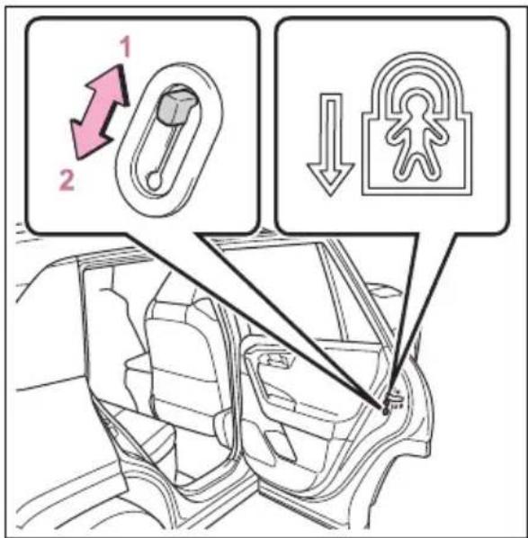
text_image
Diagram illustrating car door seat adjustment with labeled parts and directional arrows indicating movement or change.1 Unlock
2 Lock
These locks can be set to prevent children from opening the rear doors. Push down on each rear door switch to lock both rear doors.
Automatic door locking and unlocking systems
The following functions can be set or canceled:
For instructions on customizing, refer to P.706.
| Function Operation | |
| Speed linked door locking function | All doors are automatically locked when vehicle speed is approximately 12mph (20 km/h) or higher. |
| Shift position linked door locking function | All doors are automatically locked when shifting the shift lever to position other than P. |
| Shift position linked door unlocking function | All doors are automatically unlocked when shifting the shift lever to P. |
| Driver's door linked door unlocking function | All doors are automatically unlocked when driver's door is opened within approximately 45 seconds after turning the power switch to OFF. |
Back door
The back door can be locked/unlocked and opened/closed by the following procedures.

WARNING
Observe the following precautions.
Failure to do so may result in death or serious injury.
Before driving
● Make sure that the back door is fully closed.
If the back door is not fully closed, it may open unexpectedly while driving and hit nearby objects or luggage in the luggage compartment may be thrown out, causing an accident.
- Do not allow children to play in the luggage compartment. If a child is accidentally locked in the luggage compartment, they could get heat exhaustion or other injuries.
- Do not allow a child to open or close the back door. Doing so may cause the back door to operate unexpectedly, or cause the child's hands, head, or neck to be caught by the closing back door.
■ Important points while driving
- Keep the back door closed while driving. If the back door is left open, it may hit near-by objects or luggage in the luggage compartment may be thrown out, causing an accident.
● Never let anyone sit in the luggage compartment. In the event of sudden braking, sudden swerving or a collision, they are susceptible to death or serious injury.
■Back door handles
Do not hang any object to the back door handles. If any object is hung, the back door may suddenly shut, causing parts of the body to be caught, resulting in death or serious injury.
■Operating the back door
Observe the following precautions. Failure to do so may cause parts of the body to be caught, resulting in death or serious injury.
- Remove any heavy loads, such as snow and ice, from the back door before opening it. Failure to do so may cause the back door to suddenly shut again after it is opened.
- When opening or closing the back door, thoroughly check to make sure the surrounding area is safe.
- If anyone is in the vicinity, make sure they are safe and let them know that the back door is about to open or close.
- Use caution when opening or closing the back door in windy weather as it may move abruptly in strong wind.

WARNING
● Vehicles without power back door: The back door may suddenly shut if it is not opened fully. It is more difficult to open or close the back door on an incline than on a level surface, so beware of the back door unexpectedly opening or closing by itself. Make sure that the back door is fully open and secure before using the luggage compartment.
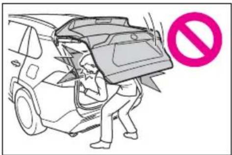
text_image
Illustration showing a person loading a car into a container with a 'no' symbol, likely indicating no vehicle use or no restriction.● Vehicles with power back door: The back door may suddenly shut if it is not opened fully, while on a steep incline. Make sure that the back door is secured before using the luggage compartment.
- When closing the back door, take extra care to prevent your fingers, etc. from being caught.
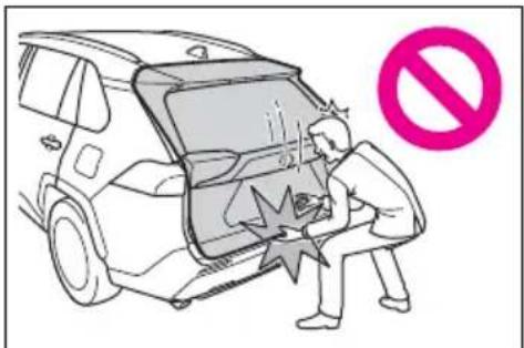
text_image
Cartoon illustration showing a person inside a vehicle with a 'no' symbol, indicating no violation or prohibition.● Vehicles without power back door: When closing the back door, make sure to press it lightly on its outer surface. If the back door handle is used to fully close the back door, it may result in hands or arms being caught.
- Do not pull on the back door damper stay (vehicles without power back door) ( P.137) or back door spindle (vehicles with power back door) ( P.144) to close the back door, and do not hang on the back door damper stay (vehicles without power back door) or back door spindle (vehicles with power back door). Doing so may cause hands to be caught or the back door damper stay (vehicles without power back door) or back door spindle (vehicles with power back door) to break, causing an accident.
- Vehicles without power back door: If a bicycle carrier or similar heavy object is attached to the back door, it may suddenly shut again after being opened, causing someone's hands, head or neck to be caught and injured. When installing an accessory part to the back door, using a genuine Toyota part is recommended.
Unlocking and locking the back door from the outside
■Using the entry function (vehicles with smart key system)
Carry the electronic key to enable this function.
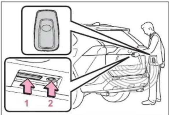
text_image
Diagram showing car door panel installation with two labeled parts and a worker inspecting the exterior panel1 Unlocks all the doors
The doors cannot be unlocked for 3 seconds after the doors are locked.
2 Locks all the doors
Check that the door is securely locked.
■ Using the wireless remote control
→P.127
Operation signals
A buzzer sounds and the emergency flashers flash to indicate that the doors have been locked/unlocked using the entry function (if equipped) or wireless remote control. (Locked: once; Unlocked: twice)
■Security feature
▶ Vehicles without smart key system
If a door is not opened within approximately 60 seconds after the vehicle is unlocked using the wireless remote control, the security feature automatically locks the vehicle again.
▶ Vehicles with smart key system
If a door is not opened within approximately 60 seconds after the vehicle is unlocked using the entry function or wireless remote control, the security feature automatically locks the vehicle again. (However, depending on the location of the
electronic key, the key may be detected as being in the vehicle. In this case, vehicle may be unlocked.)
Unlocking and locking the back door from the inside
■Using the door lock switch
→P.131
Opening/closing the back door (vehicles without power back door)
Open
Raise the back door while pressing up the back door opener switch.
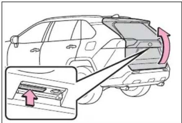
natural_image
Diagram of a car showing front and rear side views with an arrow indicating movement or change (no text or symbols present)Close
Lower the back door using the back door handle A and make sure to push the back door down from the outside to close it.
Be careful not to pull the back door sideways when closing the back door with the handle.
text_image
ALuggage compartment light
The luggage compartment light turns on when the back door is opened with the luggage compartment light switch on.
When the power switch is turned to OFF, the light will go off automatically after 20 minutes.
text_image
1 21 On
2 Off
■If the back door opener is inoperative
The back door can be unlocked from the inside.
1 Remove the cover.
To prevent damage, cover the tip of the screwdriver with a rag.
natural_image
Diagram showing a car interior with a close-up of a screwdriver inserted into a component, no text or symbols present.2 Loosen the screw.
natural_image
Diagram of a screwdriver inserted into a mechanical component with a curved arrow indicating rotation (no text or symbols present)3 Turn the cover.
natural_image
Diagram of a vehicle interior showing a handle mechanism with a pink arrow indicating direction (no text or labels)4 Move the lever.
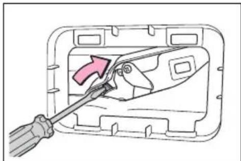
natural_image
Diagram of a screwdriver inserted into a mechanical component, showing a pink arrow indicating direction (no text or symbols present)5 When installing, reverse the steps listed.
■Open door warning buzzer →P.131

NOTICE
■Back door damper stays
The back door is equipped with damper stays that hold the back door in place.
Observe the following precautions.
Failure to do so may cause damage to the back door damper stay, resulting in malfunction.
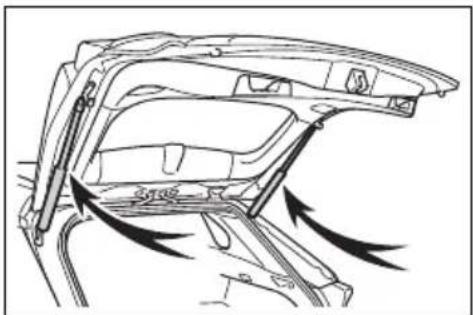
natural_image
Diagram of a car interior showing airflow or force vectors around the dashboard frame (no text or symbols)- Do not attach any foreign objects, such as stickers, plastic sheets, or adhesives to the damper stay rod.
- Do not touch the damper stay rod with gloves or other fabric items.
- Do not attach any accessories other than genuine Toyota parts to the back door.
- Do not place your hand on the damper stay or apply lateral forces to it.
Opening/closing the back door (vehicles with power back door)
■Using the wireless remote control
Press and hold the switch.
The power back door automatically opens/closes.
Pressing the switch while the power back door is opening/closing stops the operation. When the switch is pressed and held again during the halted operation, the back door will perform the reverse operation.
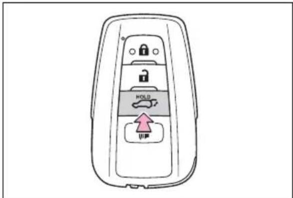
text_image
HOLD UP■Using the power back door switch on the instrument panel
Press and hold the switch.
The power back door automatically opens/closes.
Unlock the back door before operating.
Pressing the switch while the power back door is opening/closing stops the operation. When the switch is pressed and held again during the halted operation, the back door will perform the reverse operation.
text_image
Diagram showing car steering wheel and car seat with a highlighted parking sign indicating upward movement■ Using the back door opener switch
When the back door is unlocked: Press the back door
opener switch.
When the back door is locked: While carrying the electronic key on your person, press and hold the back door opener switch.
The power back door automatically opens.
Pressing the switch while the power back door is opening/closing stops the operation.
natural_image
Side view of a car showing the rear window, side door, and front panel with an arrow indicating rotation (no text or symbols)■ Using the power back door switch on the back door
Press the switch.
The power back door automatically closes.
Pressing the switch while the power back door is operating will stop the operation.
When the switch is pressed again during the halted operation, the back door will perform the reverse operation.
natural_image
Line drawing of a car backrest with an inset showing a highlighted component (no text or symbols)Lower the back door using the back door handle A
The back door closing assist ( P.140) will be activated, and the power back door will fully close automatically.
text_image
Technical diagram of a car interior showing labeled components and directional arrows indicating movement or flow.■Using the kick sensor (vehicles with Hands Free Power Back Door)
The Hands Free Power Back Door enables automatic opening and closing of the power back door by putting your foot near the lower center part of the rear bumper and moving it away from the rear bumper. When operating the Hands Free Power Back Door, make sure that the power switch is in OFF, the Hands Free Power Back Door operation is enabled (→P.109) and you are carrying an electronic key.
1 While carrying an electronic key, stand within the smart key system operation range, approximately 11.8 to 19.7 in.
(30 to 50 cm) from the rear bumper.
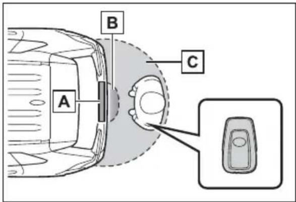
text_image
A B CA Kick sensor
B Hands Free Power Back Door operation detection area
C Smart key system operation detection area ( P.147)
2 Perform a kick operation by moving your foot to within approximately 3.9 in. (10 cm) of the rear bumper and then pulling it back.
Perform the entire kick operation within 1 second.
The back door will not start operating while a foot is detected under the rear bumper.
Operate the Hands Free Power Back Door without contacting the rear bumper with your foot.
If another electronic key is in the cabin or luggage compartment, it may take slightly longer than normal for the operation to occur.
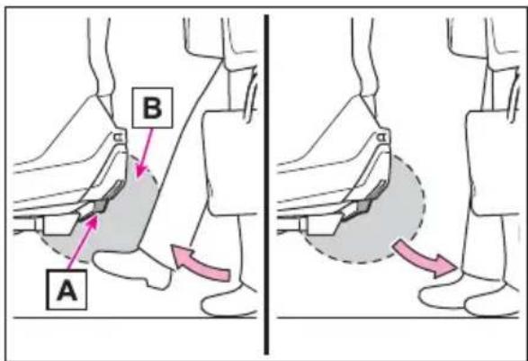
text_image
A BA Kick sensor
B Hands Free Power Back Door operation detection area
3 When the kick sensor detects that your foot is pulled back, a buzzer will sound and the back door will automatically fully open/close.
If a foot is moved under the rear bumper while the back door is opening/closing, the back door will stop moving.
If a foot is moved under the rear bumper again during the halted operation, the back door will perform the reverse operation.
Luggage compartment light
The luggage compartment light turns on when the back door is opened with the luggage compartment light switch on.
When the power switch is turned to OFF, the light will go off automatically after 20 minutes.
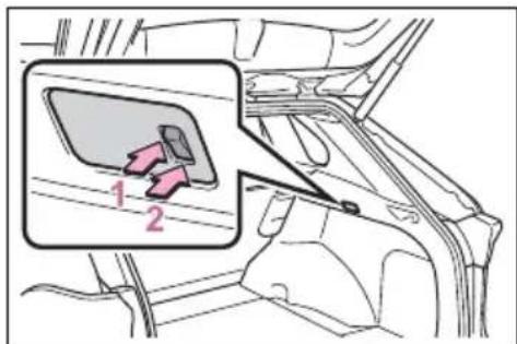
text_image
Diagram showing car seatbelt insertion into a vehicle's side panel, with labeled parts 1 and 21 On
2 Off
■Back door closer
In the event that the back door is left slightly open, the back door closer will automatically close it to the fully closed position.
Whatever the state of the power switch, the back door closer operates.
■Power back door operating conditions
The power back door can automatically open and close under the following conditions:
- When the power back door system is enabled. (→P.109)
- When the power switch is in ON, in addition to the above for the opening operations, the back door operates for any of the following conditions:
- Parking brake is engaged
• The brake pedal is depressed
• The shift lever is in P.
Operation of the power back door
●A buzzer sounds and the emergency flashers flash twice to indicate that the back door is opening/closing.
- When the power back door system is disabled, the power back door does not operate but it can be opened and closed by hand.
- When the power back door automatically opens, if an abnormality due to people or objects is detected, operation will stop.
Jam protection function
Sensors are equipped on both sides of the power back door. If anything obstructs the power back door while it is closing, the back door will automatically operate in the opposite direction or stop.
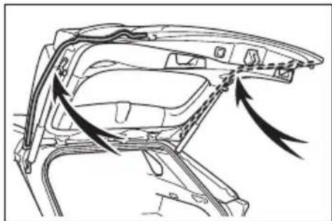
natural_image
Technical line drawing of a car interior frame with arrows indicating movement or force (no text or symbols)■Fall-down protection function
While the power back door is opening automatically, applying excessive force to it will stop the opening operation to prevent the power back door from suddenly shutting.
■Back door closing assist
If the back door is lowered manually when the back door is stopped at an open position, the back door will fully close automatically.
■Back door reserve lock function
This function is a function which reserves locking of all doors, beforehand, when the power back door is open.
When the following procedure is performed, all the doors except the power back door are locked and then power back door will also be locked at the same time it is closed.
1 Close all doors, except the back door.
2 During the power back door closing operation, lock the doors using the smart key system from the side doors ( P.127) or the wireless remote control.
( P.127)
A buzzer sounds and the emergency flashers flash to indicate that all the doors have been closed and locked.
- If the electronic key is placed inside the vehicle after starting a close operation via the door reserve lock function, the electronic key may become locked inside the vehicle.
- If the power back door does not fully close due to the operation of
the jam protection function, etc., while the back door is automatically closing after a door reserve lock operation is performed, the door reserve lock function is canceled and all the doors will unlock.
●Before leaving the vehicle, make sure that all the doors are closed and locked.
■Hands Free Power Back Door operating conditions (vehicles with Hands Free Power Back Door)
The Hands Free Power Back Door will open/close automatically when the following conditions are met:
●The Hands Free Power Back Door operation is enabled (→P.109)
●The power switch is in OFF.
●The electronic key is within the operational range. (→P.147)
● A foot is put near the lower center part of the rear bumper and moved away from the rear bumper.
The power back door may also be operated by putting a hand, an elbow, a knee, etc. near the lower center part of the rear bumper and moving it away from the rear bumper. Make sure to put it close enough to the center part of the rear bumper.
■ Situations in which the Hands Free Power Back Door may not operate properly (vehicles with Hands Free Power Back Door)
In the following situations, the Hands Free Power Back Door may not operate properly:
- When a foot remains under the rear bumper
- If the rear bumper is strongly hit with a foot or is touched for a while
If the rear bumper has been touched for a while, wait for a short time before attempting to operate the Hands Free Power Back Door again.
- When operated while a person is too close to the rear bumper
- When an external radio wave source interferes with the communication between the electronic key and the vehicle (→P.148)
- When the vehicle is parked near an electrical noise source which affects the sensitivity of the Hands Free Power Back Door, such as a pay parking spot, gas station, electrically heated road, or fluorescent light
- When the vehicle is near a TV tower, electric power plant, radio station, large display, airport or other facility that generates strong radio waves or electrical noise
- When a large amount of water is applied to the rear bumper, such as when the vehicle is being washed or in heavy rain
- When mud, snow, ice, etc. is attached to the rear bumper
- When the vehicle has been parked for a while near objects that may move and contact the rear bumper, such as plants
- When an accessory is installed to the rear bumper
If an accessory has been installed, turn the Hands Free Power Back Door operation setting off.
■Preventing unintentional operation of the Hands Free Power Back Door (vehicles with Hands Free Power Back Door)
When an electronic key is in the operation range, the Hands Free Power Back Door may operate unintentionally, so be careful in the following situations.
- When a large amount of water is applied to the rear bumper, such as when the vehicle is being washed or in heavy rain
- When dirt is wiped off the rear
bumper
- When a small animal or small object, such as a ball, moves under the rear bumper
- When an object is moved from under the rear bumper
- If someone is swinging their legs while sitting on the rear bumper
- If the legs or another part of someone's body contacts the rear bumper while passing by the vehicle
- When the vehicle is parked near an electrical noise source which affects the sensitivity of the Hands Free Power Back Door, such as a pay parking spot, gas station, electrically heated road, or fluorescent light
- When the vehicle is near a TV tower, electric power plant, radio station, large display, airport or other facility that generates strong radio waves or electrical noise
- When the vehicle is parked in a place where objects such as plants are near the rear bumper
● If luggage, etc. is set near the rear bumper
- If accessories or a vehicle cover is installed/removed near the rear bumper
- When the vehicle is being towed To prevent unintentional operation, turn the Hands Free Power Back Door operation setting off. (→P.109)
■When reconnecting the 12-volt battery
To enable the power back door to operate properly, close the back door manually.
■If the back door opener is inoperative
The back door can be unlocked from the inside.
1 Remove the cover.
To prevent damage, cover the tip of
the screwdriver with a rag.
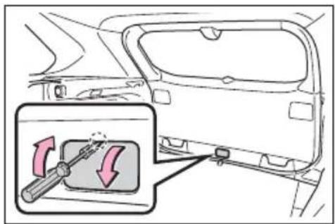
text_image
Diagram showing car door and internal component with a magnified inset highlighting the switch mechanism.2 Loosen the screw.
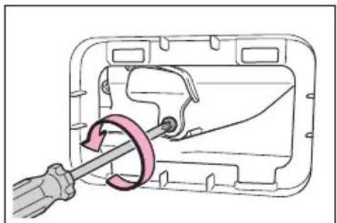
natural_image
Diagram of a mechanical component with a screwdriver inserted, showing a curved arrow indicating rotation (no text or symbols present)3 Turn the cover.
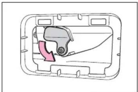
natural_image
Diagram of a mechanical component inside a rectangular housing, showing internal structure with a pink arrow indicating rotation (no text or symbols)4 Move the lever.
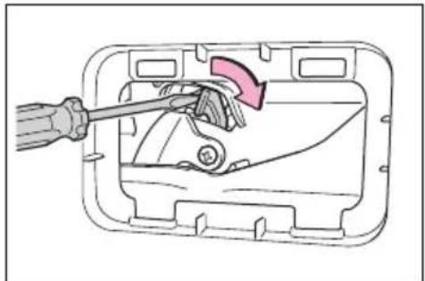
natural_image
Diagram of a screwdriver inserted into a mechanical component with a pink arrow indicating rotation (no text or symbols present)5 When installing, reverse the steps listed.
Customization
Settings (e.g. power back door opening angle) can be changed. (Customizable features: →P.711)

WARNING
■Back door closer
In the event that the back door is left slightly open, the back door closer will automatically close it to the fully closed position. It takes several seconds before the back door closer begins to operate. Be careful not to catch fingers or anything else in the back door, as this may cause bone fractures or other serious injuries.
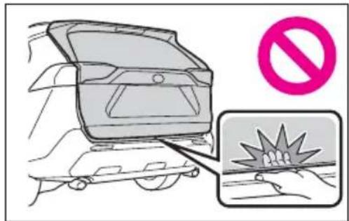
text_image
Diagram showing a car interior with a 'no stop sign' symbol and a magnified view of a collision impact on the ground.Use caution when using the back door closer as it still operates when the power back door system is canceled.
Power back door
Observe the following precautions when operating the power back door.
Failure to do so may cause death or serious injury.
- Check the safety of the surrounding area to make sure there are no obstacles or anything that could cause any of your belongings to get caught.
- If anyone is in the vicinity, make sure they are safe and let them know that the back door is about to open or close.
- If the power back door system is turned off while the back door is operating automatically, the automatic operation is stopped. The back door then has to be operated manually. Take extra care when on an incline, as the back door may open or close unexpectedly.
- If the operating conditions of the power back door are no longer met, a buzzer may sound and the back door may stop opening or closing. The back door then has to be operated manually. Take extra care when on an incline, as the back door may open or close abruptly.
● On an incline, the back door may suddenly shut after it opens. Make sure the back door is fully open and secure.
In the following situations, the power back door may detect an abnormality and automatic operation may be stopped. In this case, the back door has to be operated manually. Take extra care when on an incline, as the back door may open or close abruptly.
- When the back door contacts an obstacle
- When the 12-volt battery voltage suddenly drops, such as when the power switch is turned to ON or the hybrid system is started during automatic operation
- If a bicycle carrier or similar heavy object is attached to the back door, it may suddenly shut again after being opened, causing someone's hands, head or neck to be caught and injured. When installing an accessory part to the back door, using a genuine Toyota part is recommended.

WARNING
Jam protection function
Observe the following precautions.
Failure to do so may cause death or serious injury.
●Never use any part of your body to intentionally activate the jam protection function.
●The jam protection function may not work if something gets caught just before the back door fully closes. Be careful not to catch fingers or anything else.
●The jam protection function may not work depending on the shape of the object that is caught. Be careful not to catch fingers or anything else.
■Hands Free Power Back Door (if equipped)
Observe the following precautions when operating the Hands Free Power Back Door.
Failure to do so may cause death or serious injury.
- Check the safety of the surrounding area to make sure there are no obstacles or anything that could cause any of your belongings to get caught.
- When putting your foot near the lower center part of the rear bumper and moving it from the rear bumper, be careful not to touch the exhaust pipes until they have cooled down sufficiently, as touching hot exhaust pipes can cause burns.
- Do not leave the electronic key within the effective range (detection area) of the luggage compartment.

NOTICE
■Back door spindles
The back door is equipped with spindles that hold the back door in place.
Observe the following precautions.
Failure to do so may cause damage to the back door spindle, resulting in malfunction.
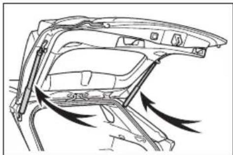
natural_image
Diagram of a car interior showing structural components and airflow direction (no text or labels)- Do not attach any foreign objects, such as stickers, plastic sheets, or adhesives to the spindle rod.
- Do not touch the spindle rod with gloves or other fabric items.
- Do not attach heavy accessories to the back door. When attaching, ask your Toyota dealer for details.
- Do not place your hand on the spindle or apply lateral forces to it.
■To prevent back door closer malfunction
Do not apply excessive force to the back door while the back door closer is operating. Applying excessive force may cause the back door closer to malfunction.

NOTICE
■To prevent damage to the power back door
Make sure that there is no ice between the back door and frame that would prevent movement of the back door. Operating the power back door when excessive load is present on the back door may cause a malfunction.
- Do not apply excessive force to the back door while the power back door is operating.
●Take care not to damage the sensors (installed on the right and left edges of the power back door) with a knife or other sharp object. If the sensor is disconnected, the power back door will not close automatically.
■Hands Free Power Back Door precautions (if equipped)
The kick sensor is located behind lower center part of the rear bumper. Observe the following to ensure that the Hands Free Power Back Door function operates properly:
- Keep the lower center part of the rear bumper clean at all times. If the lower center part of the rear bumper is dirty or covered with snow, the kick sensor may not operate. In this situation, clean off the dirt or snow, move the vehicle from the current position and then check if the kick sensor operates. If it does not operate, have the vehicle inspected by your Toyota dealer.
- Do not apply coatings that have a rain clearing (hydrophilic) effect, or other coatings, to the lower center part of the rear bumper.
- Do not park the vehicle near objects that may move and contact the lower center part of the rear bumper, such as grass or trees. If the vehicle has been parked for a while near objects that may move and contact the lower center part of the rear bumper, such as grass or trees, the kick sensor may not operate. In this situation, move the vehicle from the current position and then check if the kick sensor operates. If it does not operate, have the vehicle inspected by your Toyota dealer.
- Do not subject the kick sensor or its surrounding area to a strong impact. If the kick sensor or its surrounding area has been subjected to a strong impact, the kick sensor may not operate properly. If the kick sensor does not operate in the following situations, have the vehicle inspected by your Toyota dealer.
- The kick sensor or its surrounding area has been subjected to a strong impact. - The lower center part of the rear bumper is scratched or damaged.
- Do not disassemble the rear bumper.
- Do not attach stickers to the rear bumper.
- Do not paint the rear bumper.

NOTICE
- If a bicycle carrier or similar heavy object is attached to the power back door, disable the Hands Free Power Back Door. (→P.109)
Changing settings of the power back door system (vehicles with power back door)
The settings of the power back door system can be changed by displaying the “Vehicle Settings” - “PBD” screen from the

screen of the multi-informa- n display. (→P.109)
The changed power back door settings are not reset by turning the power switch to OFF. In order to restore the original settings, they need to be changed back on the

screen of the multi-information play.
Adjusting the open position of the back door (vehicles with power back door)
The open position of the power back door can be adjusted.
1 Stop the back door in the desirable position. (→P.137)
2 Press and hold the power back door switch on the back door for approximately 2 seconds.
When the settings are completed, the buzzer sounds 4 times.
When opening the back door the next time, the back door will stop at that position.
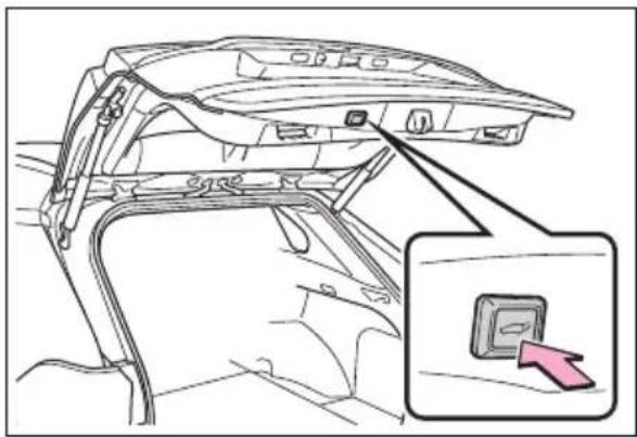
natural_image
Diagram of a car interior showing the front compartment and a highlighted switch (no text or symbols present)■ Canceling the adjusted open position of the back door
Press and hold the power back door switch on the back door for approximately 7 seconds.
After the buzzer sounds 4 times, it sounds twice more. When the power back door does the opening operation the next time, the door will open to the initial settings position.
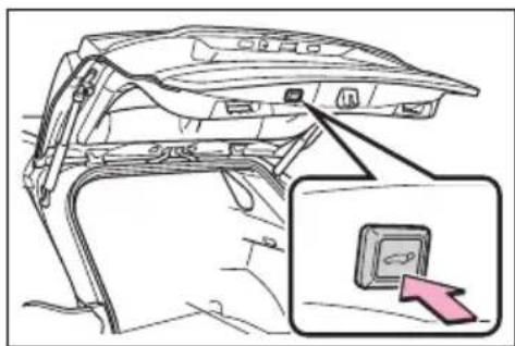
natural_image
Line drawing of a car interior showing the front panel and door, with an inset close-up of a button labeled 'Close' pointing to it (no text or symbols on the main diagram)Customization
The opening position can be set with the multi-information display. (→P.109)
Priority for the stop position is given to the last position set by either the power back door switch on the back door or multi-information display.
Smart key system\*
*: If equipped
The following operations can be performed simply by carrying the electronic key on your person, for example in your pocket. The driver should always carry the electronic key.
- Locks and unlocks the side doors (→P.127)
- Locks and unlocks the back door (→P.134)
- Starts the hybrid system (→P.212)
Antenna location
text_image
A B C A B D A B C DA Antennas outside the cabin (front)
B Antennas outside the cabin (rear) (if equipped)
C Antenna outside the luggage compartment
D Antennas inside the cabin
■Effective range (areas within which the electronic key is detected)
text_image
A BA When locking or unlocking the doors
The system can be operated when the electronic key is within about 2.3 ft. (0.7 m) of the front door handles, rear door handles (if equipped) and back door opener switch. (Only the doors detecting the key can be operated.)
B When starting the hybrid system or changing power switch modes
The system can be operated when the electronic key is inside the vehicle.
If an alarm sounds or a warning message is displayed
An alarm sounds and warning message displays shown on the multi-information display are used to protect against unexpected accidents or theft of the vehicle resulting from erroneous operation. When a warning message is displayed, take appropriate measures based on the displayed message.
When only an alarm sounds, circumstances and correction procedures are as follows.
- When an exterior alarm sounds once for 5 seconds
| Situation | Correction procedure |
| An attempt was made to lock the vehicle while a door was open. | Close all of the doors and lock the doors again. |
- When an interior alarm pings continuously
| Situation | Correction procedure |
| The power switch was turned to ACC while the driver's door was open (or the driver's door was opened while the power switch was in ACC). | Turn the power switch to OFF and close the driver's door. |
■Battery-saving function
The battery-saving function will be activated in order to prevent the electronic key battery and the 12-volt battery from being discharged while the vehicle is not in operation for a long time.
● In the following situations, the smart key system may take some time to unlock the doors.
- The electronic key has been left in an area of approximately 6 ft. (2 m) of the outside of the vehicle for 10 minutes or longer.
- The smart key system has not been used for 5 days or longer.
- If the smart key system has not been used for 14 days or longer, the doors cannot be unlocked at any doors except the driver's door. In this case, take hold of the driver's door handle, or use the wireless remote control or the
mechanical key, to unlock the doors.
■Turning an electronic key to battery-saving mode
- When battery-saving mode is set, battery depletion is minimized by stopping the electronic key from receiving radio waves.
Press twice while pressing
and holding .
Confirm that the electronic key indicator flashes 4 times.
While the battery-saving mode is set, the smart key system cannot be used. To cancel the function, press any of the electronic key buttons.
text_image
Diagram of a car door with control panel and indicator lights, showing '=OLD' function buttons●Electronic keys that will not be used for long periods of time can be set to the battery-saving mode in advance.
■Conditions affecting operation
The smart key system uses weak radio waves. In the following situations, the communication between the electronic key and the vehicle may be affected, preventing the smart key system, wireless remote control and immobilizer system from operating properly.
(Ways of coping: →P.670)
- When the electronic key battery is depleted
●Near a TV tower, electric power plant, gas station, radio station, large display, airport or other facility that generates strong radio waves or electrical noise - When the electronic key is in con-
tact with, or is covered by the following metallic objects
- Cards to which aluminum foil is attached
• Cigarette boxes that have aluminum foil inside
• Metallic wallets or bags - Coins
- Hand warmers made of metal
• Media such as CDs and DVDs
- When other wireless key (that emits radio waves) is being used nearby
- When carrying the electronic key together with the following devices that emit radio waves
- Portable radio, cellular phone, cordless phone or other wireless communication devices
- Another vehicle's electronic key or a wireless key that emits radio waves
• Personal computers or personal digital assistants (PDAs)
• Digital audio players
- Portable game systems
- If window tint with a metallic content or metallic objects are attached to the rear window
- When the electronic key is placed near a battery charger or electronic devices
- When parking in a coin-operated parking lot (Radio waves used to detect vehicles may affect the smart key system.)
■Note for the entry function
● Even when the electronic key is within the effective range (detection areas), the system may not operate properly in the following cases:
- The electronic key is too close to the window or outside door handle, near the ground, or in a high place when the doors are locked or unlocked.
- The electronic key is on the instrument panel, luggage cover or floor, or in the door pockets or glove box when the hybrid system
is started or power switch modes are changed.
- Do not leave the electronic key on top of the instrument panel or near the door pockets when exiting the vehicle. Depending on the radio wave reception conditions, it may be detected by the antenna outside the cabin and the door will become lockable from the outside, possibly trapping the electronic key inside the vehicle.
- As long as the electronic key is within the effective range, the doors may be locked or unlocked by anyone. However, only the doors detecting the electronic key can be used to unlock the vehicle.
● Even if the electronic key is not inside the vehicle, it may be possible to start the hybrid system if the electronic key is near the window.
●The doors may unlock if a large amount of water splashes on the door handle, such as in the rain or in a car wash when the electronic key is within the effective range. (The doors will automatically be locked after approximately 60 seconds if the doors are not opened and closed.)
- If the wireless remote control is used to lock the doors when the electronic key is near the vehicle, there is a possibility that the door may not be unlocked by the entry function. (Use the wireless remote control to unlock the doors.)
●Touching the door lock sensor while wearing gloves may delay or prevent lock operation. Remove the gloves and touch the lock sensor again.
- When the lock operation is performed using the lock sensor, recognition signals will be shown up to two consecutive times. After this, no recognition signals will be given.
- If the door handle becomes wet while the electronic key is within
the effective range, the door may lock and unlock repeatedly. In that case, follow the following correction procedures to wash the vehicle:
- Place the electronic key in a location 6 ft. (2 m) or more away from the vehicle. (Take care to ensure that the key is not stolen.)
- Set the electronic key to battery-saving mode to disable the smart key system. (→P.148)
- If the electronic key is inside the vehicle and a door handle becomes wet during a car wash, a message may be shown on the multi-information display and a buzzer will sound outside the vehicle. To turn off the alarm, lock all the doors.
●The lock sensor may not work properly if it comes into contact with ice, snow, mud, etc. Clean the lock sensor and attempt to operate it again, or use the lock sensor on the lower part of the door handle.
●A sudden approach to the effective range or door handle may prevent the doors from being unlocked. In this case, return the door handle to the original position and check that the doors unlock before pulling the door handle again.
- If there is another electronic key in the detection area, it may take slightly longer to unlock the doors after the door handle is gripped.
■When the vehicle is not driven for extended periods
● To prevent theft of the vehicle, do not leave the electronic key within 6 ft. (2 m) of the vehicle.
●The smart key system can be deactivated in advance. (→P.710)
●Battery-saving mode can reduce the power consumption of electronic keys. (→P.148)
■To operate the system properly
Make sure to carry the electronic key when operating the system. Do not get the electronic key too close to the vehicle when operating the system from the outside of the vehicle.
Depending on the position and holding condition of the electronic key, the key may not be detected correctly and the system may not operate properly. (The alarm may go off accidentally, or the door lock prevention may not operate.)
■If the smart key system does not operate properly
- Locking and unlocking the doors: Use the mechanical key. (→P.670)
● Starting the hybrid system: →P.671
Customization
Settings (e.g. smart key system) can be changed. (Customizable features: →P.709)
If the smart key system has been deactivated in a customized setting, refer to the explanations for the following operations.
- Locking and unlocking the doors: Use the wireless remote control or mechanical key. (→P.127, 670)
● Starting the hybrid system and changing power switch modes: →P.671
●Stopping the hybrid system: →P.214
■Certification for the smart key system
For vehicles sold in the U.S.A., Hawaii, American Samoa, Guam, Saipan and Puerto Rico
FCC ID: NI4TMLF15-1
This device complies with part 15 of the FCC Rules. Operation is subject to the following two conditions: (1) This device may not cause harmful interference, and (2) this device must accept any interference received, including interference that may cause undesired operation.
Changes or modifications not expressly approved by the party responsible for compliance could void the user's authority to operate the equipment.
FCC ID:HYQ23AAY
FCC ID:HYQ14FBC
NOTE:
This device complies with part 15 of the FCC Rules. Operation is subject to the following two conditions: (1) This device may not cause harmful interference, and (2) this device must accept any interference received, including interference that may cause undesired operation.
FCC WARNING:
Changes or modifications not expressly approved by the party responsible for compliance could void the user's authority to operate the equipment.
For vehicles sold in Canada
This device complies with Industry Canada's licence-exempt RSSs. Operation is subject to the following two conditions: (1) This device may not cause interference; and (2) This device must accept any interference, including interference that may cause undesired operation of the device.
This device contains licence-exempt transmitter(s)/receiver(s) that comply with Innovation, Science and Economic Development Canada's licence-exempt RSS(s).
Operation is subject to the following two conditions:
(1) This device may not cause interference.
(2) This device must accept any interference, including interference that may cause undesired operation of the device.
NOTE:
■Caution regarding interference with electronic devices
●People with implantable cardiac pacemakers, cardiac resynchronization therapy-pacemakers or implantable cardioverter defibrillators should maintain a reasonable distance between themselves and the smart key system antennas. (→P.147)
The radio waves may affect the operation of such devices. If necessary, the entry function can be disabled. Ask your Toyota dealer for details, such as the frequency of radio waves and timing of the emitted radio waves. Then, consult your doctor to see if you should disable the entry function.
- Users of any electrical medical device other than implantable cardiac pacemakers, cardiac resynchronization therapy-pacemakers or implantable cardioverter defibrillators should consult the manufacturer of the device for information about its operation under the influence of radio waves.
Radio waves could have unexpected effects on the operation of such medical devices.
Ask your Toyota dealer for details on disabling the entry function.
Front seats
The seats can be adjusted (longitudinally, vertically, etc.). Adjust the seat to ensure the correct driving posture.
Adjustment procedure
▶ Manual seat
text_image
1 2 31 Seat position adjustment lever
2 Seatback angle adjustment lever
3 Vertical height adjustment lever (driver's side only)
Power seat (driver's side only)
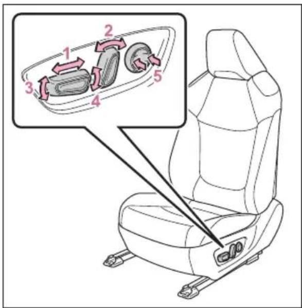
text_image
Diagram of car seat assembly with numbered parts and directional arrows indicating movement or positioning1 Seat position adjustment switch
2 Seatback angle adjustment switch
3 Seat cushion (front) angle adjustment switch
4 Vertical height adjustment switch
5 Lumbar support adjustment switch
■When adjusting the seat
Take care when adjusting the seat so that the head restraint does not touch the ceiling.

WARNING
■When adjusting the seat position
Take care when adjusting the seat position to ensure that other passengers are not injured by the moving seat.

WARNING
- Do not put your hands under the seat or near the moving parts to avoid injury.
Fingers or hands may become jammed in the seat mechanism.
Make sure to leave enough space around the feet so they do not get stuck.
●Manual seat only: After adjusting the seat, make sure that the seat is locked in position.
■Seat adjustment
To reduce the risk of sliding under the lap belt during a collision, do not recline the seat more than necessary.
If the seat is too reclined, the lap belt may slide past the hips and apply restraint forces directly to the abdomen, or your neck may contact the shoulder belt, increasing the risk of death or serious injury in the event of an accident. Adjustments should not be made while driving as the seat may unexpectedly move and cause the driver to lose control of the vehicle.
Rear seats
Reclining adjustments and folding the seatbacks can be done with lever operation.
Adjustment procedure
Pull the seatback angle adjustment lever A and adjust the seatback angle.
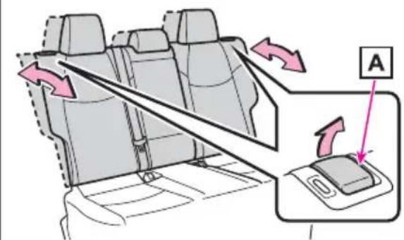
text_image
Diagram showing car seatbelting mechanism with directional arrows and labeled component A
WARNING
■When operating the seatback
Observe the following precautions.
Failure to do so may cause death or serious injury.
- Keep other passengers from being hit with the seatback.
- Do not bring your hands close to the moving parts or between the seats, as well as do not let any part of your body get caught.

WARNING
●After adjusting the seat, make sure that the seat is locked in position. If the seatback is not securely locked, the red marking will be visible. Make sure that the red marking is not visible.
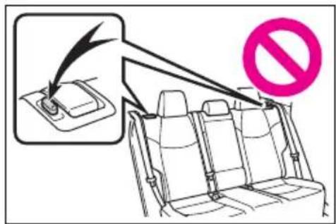
text_image
Diagram showing car seatbelt switch and no-noise symbol in a vehicle seatbelt, with magnified view of the switch.Folding down the rear seatbacks
■Before folding down the seatbacks
1 Park the vehicle in a safe place.
Apply the parking brake ( P.224) and shift the shift lever to P. ( P.220)
2 Adjust the position of the front seat and the angle of the seatback. (→P.153)
Depending on the position of the front seat, if the seatback is folded backward, it may interfere with the operation of the rear seat.
3 Lift up and push down the head restraints of the rear outboard seats, and lower the head restraint of the rear center seat. (→P.159)
4 Stow the armrest of the rear seat if it is pulled out. ( P.556)
This step is not necessary when operating the left side seat only.
■ Folding down the seat-backs
While pulling the seatback angle adjustment lever Afold the seatback down.
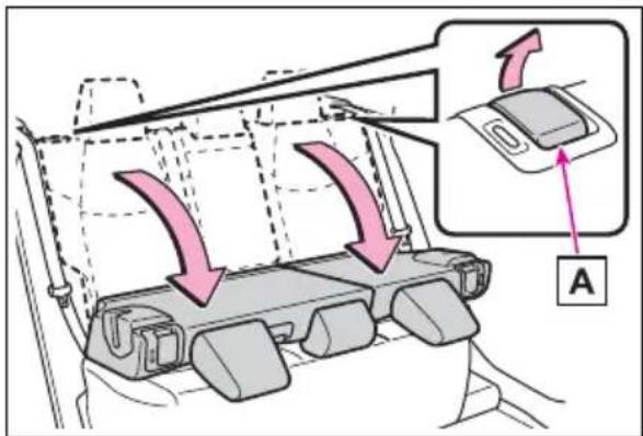
text_image
Diagram showing airflow or traffic flow from a vehicle seat to the dashboard, with labeled component A and directional arrows.■Returning the rear seat-backs
To avoid trapping the seat belt between the seat and the inside of the vehicle, pass the seat belt outside the seat belt guide A and then return the seatback securely to the locked position.

text_image
A
WARNING
Observe the following precautions. Failure to do so may result in death or serious injury.

WARNING
■When folding the rear seat-backs down
- Do not fold the seatbacks down while driving.
- Stop the vehicle on level ground, set the parking brake and shift the shift lever to P.
- Do not allow anyone to sit on a folded seatback or in the luggage compartment while driving.
- Do not allow children to enter the luggage compartment.
- Do not operate the rear seat if it is occupied.
● Be careful not to get feet or hands caught in the moving parts or joints of the seats during operation.
- Do not allow children to operate the seat.
■After returning the rear seat-back to the upright position
● Make sure that the seatback is securely locked in position by lightly pushing it back and forth. If the seatback is not securely locked, the red marking will be visible. Make sure that the red marking is not visible.
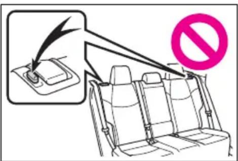
text_image
Diagram showing car seatbelt switch and no stop sign in a vehicle, with magnified view of the switch being lifted.- Check that the seat belts are not twisted or caught in the seatback.
Driving position memory\*
*: If equipped
This feature automatically adjusts the driver's seat to suit your preferences.
Your preferred driving position (the position of the driver's seat) can be recorded and recalled by pressing a button.
Two different driving positions can be recorded into memory.
Each electronic key can be registered to recall your preferred driving position.
Recording/recalling a driving position
■Recording procedure
1 Check that the shift lever is in P.
2 Turn the power switch to ON.
3 Adjust the driver's seat to the desired positions.
4 While pressing the "SET" button, or within 3 seconds after the "SET" button is pressed, press button "1" or "2" until the buzzer sounds.
If the selected button has already been preset, the previously recorded position will be overwrit-
ten.
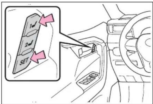
text_image
1 2 SET■Recall procedure
1 Check that the shift lever is in P.
2 Turn the power switch to ON.
3 Press one of the buttons for the driving position you want to recall until the buzzer sounds.
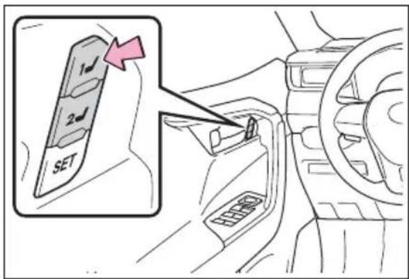
text_image
1 2 SET■To stop the position recall operation part-way through
Perform any of the following:
- Press the "SET" button.
- Press button "1" or "2".
- Operate any of the seat adjustment switches.
■ Seat positions that can be memorized (→P.153)
The adjusted positions other than the position adjusted by lumbar support switch can be recorded.
■ Operating the driving position memory after turning the power switch to OFF
Recorded seat positions can be activated up to 180 seconds after the driver's door is opened and another 60 seconds after it is closed again.
In order to correctly use the driving position memory function
If a seat position is already in the furthest possible position and the seat is operated in the same direction, the recorded position may be slightly different when it is recalled.
■When recalling the driving position
Take care when recalling the driving position so that the head restraint does not touch the ceiling.
■If the 12-volt battery is disconnected
The memorized positions are erased.
■When the recorded seat position cannot be recalled
The seat position may not be recalled in some situations when the seat position is recorded in a certain range. For details, contact your Toyota dealer.

WARNING
■Seat adjustment caution
Take care during seat adjustment so that the seat does not strike the rear passenger or squeeze your body against the steering wheel.
Registering/recall/cancel- ing a driving position to an electronic key (mem- ory recall function)
■Registering procedure
Record your driving position to button "1" or "2" before performing the following:
Carry only the key you want to register, and then close the driver's door.
If 2 or more keys are in the vehicle, the driving position cannot be recorded properly.
1 Check that the shift lever is in P.
2 Turn the power switch to ON.
3 Recall the driving position that you want to record.
4 While pressing the recalled button, press and hold the door lock switch (either lock or unlock) until the buzzer sounds.
If the button could not be registered, the buzzer sounds continuously for approximately 3 seconds.
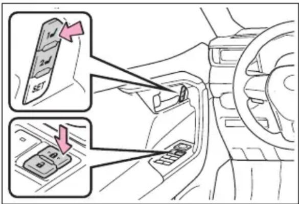
text_image
1 2 SET■Recall procedure
Make sure that the doors are
locked before recalling the driving position. Carry the electronic key that has been registered to the driving position, and then unlock and open the driver's door using the smart key system or wireless remote control.
The driving position will move to the recorded position.
If the driving position is in a position that has already been recorded, the seat will not move.
■Cancelation procedure
Carry only the key you want to cancel and then close the driver's door.
If 2 or more keys are in the vehicle, the driving position cannot be canceled properly.
1 Check that the shift lever is in P.
2 Turn the power switch to ON.
3 While pressing the "SET" button, press and hold the door lock switch (either lock or unlock) until the buzzer sounds twice.
If the button could not be canceled, the buzzer sounds continuously for approximately 3 seconds.
■Recalling the driving position using the memory recall function
● Different driving positions can be registered for each electronic key. Therefore, the driving position that is recalled may be different depending on the key being carried.
- If a door other than the driver's
door is unlocked with smart key system, the driving position cannot be recalled. In this case, press the driving position button which has been set.
Customization
Settings (e.g. the unlock door settings of the memory recall function) can be customized. (Customizable features: →P.712)
Head restraints
Head restraints are provided for all seats.

WARNING
■Head restraint precautions
Observe the following precautions regarding the head restraints. Failure to do so may result in death or serious injury.
- Use the head restraints designed for each respective seat.
- Adjust the head restraints to the correct position at all times.
● After adjusting the head restraints, push down on them and make sure they are locked in position. - Do not drive with the head restraints removed.
Vertical adjustment
Front seats
text_image
1 2 A1 Up
Pull the head restraints up.
2 Down
Push the head restraint down while pressing the lock release button
A.
■ Center rear seat
text_image
1 2 A1 Up
Pull the head restraints up.
2 Down
Push the head restraint down while pressing the lock release button
A.
■Outboard rear seats
Head restraints cannot be adjusted.
■Adjusting the height of the head restraints (front seats)
Make sure that the head restraints are adjusted so that the center of the head restraint is closest to the top of your ears.
natural_image
Side profile illustration of a person with shoulder and arm anatomy, showing anatomical alignment (no text or symbols)■Adjusting the center rear seat head restraint
Always raise the head restraint one level from the stowed position when using.
Removing the head restraints
Pull the head restraint up while pressing the lock release button A.
If the head restraint touches the ceiling, making the removal difficult, change the seat height or angle. (→P.153)
text_image
AInstalling the head restraints
■Front and center rear seats
Align the head restraint with the installation holes and push it down to the lock position.
Press and hold the lock release button A when lowering the head restraint.
text_image
Diagram showing a sewing machine head with a pink downward arrow and labeled component 'A'■Outboard rear seats
Align the head restraint with the installation holes and push it down to the lowest lock position.
natural_image
Illustration of a gray electronic component with two legs and a pink downward arrow pointing to its base (no text or symbols)Steering wheel
Adjustment procedure
1 Hold the steering wheel and push the lever down.
natural_image
Interior view of a car dashboard and steering wheel, showing steering wheel and dashboard (no text or symbols)2 Adjust to the ideal position by moving the steering wheel horizontally and vertically.
After adjustment, pull the lever up to secure the steering wheel.
natural_image
Diagram of a car's steering wheel and dashboard with three pink arrows indicating clockwise motion (no text or symbols)
WARNING
■Caution while driving
Do not adjust the steering wheel while driving.
Doing so may cause the driver to mishandle the vehicle and cause an accident, resulting in death or serious injury.
■After adjusting the steering wheel
Make sure that the steering wheel is securely locked.
Otherwise, the steering wheel may move suddenly, possibly causing an accident, and resulting in death or serious injury. Also, the horn may not sound if the steering wheel is not securely locked.
Sounding the horn
To sound the horn, press on or close to the mark.
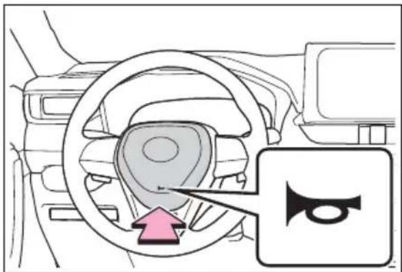
natural_image
Interior view of a car showing steering wheel and dashboard with a highlighted directional arrow (no text or symbols)Inside rear view mir- ror\*
*: If equipped
The rear view mirror's position can be adjusted to enable sufficient confirmation of the rear view.
Adjusting the height of rear view mirror
The height of the rear view mirror can be adjusted to suit your driving posture.
Adjust the height of the rear view mirror by moving it up and down.
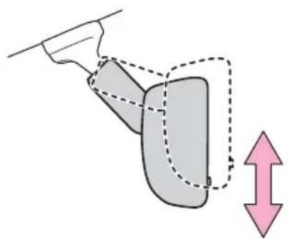
natural_image
Diagram showing a hand holding a tool interacting with a shaded object, with a pink double-headed arrow indicating vertical displacement (no text or symbols)
WARNING
■Caution while driving
Do not adjust the position of the mirror while driving. Doing so may lead to mishandling of the vehicle and cause an accident, resulting in death or serious injury.
Anti-glare function (vehicles with manual anti-glare inside rear view mirror)
Reflected light from the headlights of vehicles behind can be reduced by operating the lever.
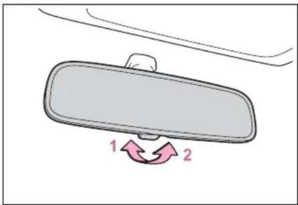
text_image
1 21 Normal position
2 Anti-glare position
Anti-glare function (vehicles with auto anti-glare inside rear view mirror)
Responding to the level of brightness of the headlights of vehicles behind, the reflected light is automatically reduced.
Changing automatic anti-glare function mode on/off
When the automatic anti-glare function is in ON mode, the indicator A illuminates.
The function will set to ON mode each time the power switch is turned to ON.
Pressing the button turns the function to OFF mode. (The indicator
A also turns off.)
▶ Vehicles without garage door opener
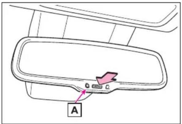
text_image
A▶ Vehicles with garage door opener
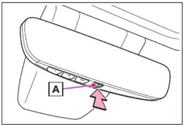
text_image
A■To prevent sensor error (vehicles with auto anti-glare inside rear view mirror)
To ensure that the sensors operate properly, do not touch or cover them.
▶ Vehicles without garage door opener
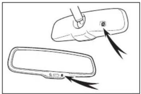
natural_image
Diagram showing a car rearview mirror with a tool inserted, and its side view with arrows indicating force or motion (no text or symbols)▶ Vehicles with garage door opener
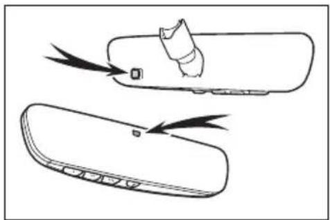
natural_image
Line drawing of a device with a handle and two views of the lid (no text or symbols)Digital Rear-view Mirror
*: If equipped
The Digital Rear-view Mirror is a system that uses the camera on the rear of the vehicle and displays its image on the display of the Digital Rear-view Mirror.
The Digital Rear-view Mirror can be changed between optical mirror mode and digital mirror mode by operating the lever.
The Digital Rear-view Mirror allows the driver to see the rear view despite obstructions, such as the head restraints or luggage, ensuring rear visibility. Also, the rear seats are not displayed and privacy of the passengers is enhanced.

WARNING
Observe the following precautions.
Failure to do so may result in death or serious injury.
■Before using the Digital Rear-view Mirror
● Make sure to adjust the mirror before driving. (→P.167)
- Change to optical mirror mode and adjust the position of the Digital Rear-view Mirror so that the area behind your vehicle can be viewed properly.
- Change to digital mirror mode and adjust the display settings.
As the range of the image displayed by the Digital Rear-view Mirror is different from that of the optical mirror, make sure to check this difference before driving.
System components
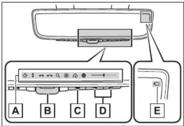
text_image
Diagram showing car interior control panel with labeled buttons A, B, C, D and connection points EA Icon display area
Displays icons, adjusting gauge, etc. ( P.167)
B Lever
Operate to change between digital mirror mode and optical mirror mode.
C Menu button
Press to display the icon display area and select the item you want to adjust.
D Select/adjust button
Press to change the setting of the item you want to adjust.
E Camera indicator
Indicates that the camera is operating normally.
Changing modes
Operate the lever to change between digital mirror mode and optical mirror mode.
text_image
Diagram showing a car interior component with labeled parts and directional arrows indicating movement or rotation.1 Digital mirror mode
Displays an image of the area behind the vehicle.
will illuminate in this mode.
2 Optical mirror mode
Turns off the display of the Digital Rear-view Mirror allows it to be used as an optical mirror.
■Digital mirror mode operating condition
The power switch is turned to ON.
When the power switch is changed from ON to OFF or ACC, the image will disappear after several seconds.
■When using the Digital Rear-view Mirror in digital mirror mode
- If it is difficult to see the displayed image due to light reflected off the Digital Rear-view Mirror, the camera being dirty or covered with water droplets, or if lights of a vehicle behind your vehicle or the displayed image are bothering you, change to optical mirror mode.
- When the back door is open, the Digital Rear-view Mirror image may not display properly. Before
driving, make sure the back door is closed.
- If the display is difficult to see due to reflected light, close the sun-shade for the moon roof (if equipped) or the electronic sun-shade for the panoramic moon roof (if equipped).
● Any of the following conditions may occur when driving in the dark, such as at night. None of them indicates that a malfunction has occurred. - Colors of objects in the displayed image may differ from their actual color.
- Depending on the height of the lights of the vehicle behind, the area around the vehicle may appear white and blurry.
• Automatic image adjustment for brighter surrounding image may cause flickering.
If it is difficult to see the displayed image or flickering bothers you, change to optical mirror mode.
●The Digital Rear-view Mirror may become hot while it is in digital mirror mode.
This is not a malfunction.
●Depending on your physical condition or age, it may take longer than usual to focus on the displayed image. In this case, change to optical mirror mode.
- Do not let passengers stare at the displayed image when the vehicle is being driven, as doing so may cause motion sickness.
■When the system malfunctions
If the symbol shown in the illustration is displayed when using the Digital Rear-view Mirror in digital mirror mode, the system may be malfunctioning. The symbol will disappear in a few seconds. Operate the lever, change to optical mirror mode and have the vehicle inspected by your Toyota dealer.
natural_image
Diagram showing a door panel with a cursor pointing at the bottom panel and a button, no text or symbols present.Adjusting the mirror
■Adjusting the mirror height
The height of the rear view mirror can be adjusted to suit your driving posture.
Change to optical mirror mode, adjusting the height of the rear view mirror by moving it up and down.
natural_image
Illustration of a car seatbelt buckle being adjusted, showing no text or symbols■Display settings (digital mirror mode)
Settings of the display in the digital mirror mode, on/off operation of the automatic anti-glare function, etc. can be changed.
1 Press the menu button.
The icons will be displayed.
text_image
Diagram of a car front panel with directional control buttons and a pink arrow pointing to the bottom panel.2 Press the menu button repeatedly and select the item you want to adjust.
3 Press or to change the setting.
The icons will disappear if a button is not operated for approximately 5 seconds or more.
| Icons | Settings |
| Select to adjust the brightness of the display. | |
| Select to adjust the area displayed up/down. | |
| Select to adjust the area displayed to the left/right. | |
| Select to adjust the angle of the displayed image. | |
| Select to zoom in/out the displayed image. | |
| Icons Settings | |
| Select to enable/disable the automatic anti-glare function.*Responding to the brightness of the headlights of vehicles behind, the reflected light is automatically adjusted.The automatic anti-glare function is enabled each time the power switch is changed to ON. | |
| Select to displayHomeLink® Training Tutorial to assist customers to train their Garage Door Opener System. (→P.557) | |
| Select to change the language of the Homelink® Training Tutorial. | |
*: This is a function for the optical mirror mode, however, the setting can also be changed while using the digital mirror mode.
■Enabling/disabling the automatic anti-glare function (optical mirror mode)
The automatic anti-glare function in the optical mirror mode can be enabled/disabled. The setting can be changed in both the digital mirror mode and the optical mirror mode.
▶ When using the digital mirror mode
→P.167
▶ When using the optical mirror mode
1 Press the menu button.
The icons will be displayed.
2 Press the menu button repeatedly and select
The setting display will be displayed.
text_image
OFF ON3 Press or to enable (ON)/disable (OFF) the automatic anti-glare function.
The icons will disappear if a button is not operated for approximately 5 seconds or more.
■Adjusting the display (digital mirror mode)
- If the displayed image is adjusted, it may appear distorted. This is not a malfunction.
- If the brightness of the Digital Rear-view Mirror is set too high, it may cause eye strain. Adjust the Digital Rear-view Mirror to an appropriate brightness. If your eyes become tired, change to optical mirror mode.
●The brightness of the Digital Rearview Mirror will change automatically according to the brightness of the area in front of your vehicle.
■To prevent the light sensors from malfunctioning
To prevent the light sensors from malfunctioning, do not touch or cover them.
natural_image
Diagram showing a car interior with a hand pressing down on the windshield and a hand holding a device, alongside a close-up of the dashboard (no text or symbols present)
WARNING
Observe the following precautions.
Failure to do so may result in death or serious injury.
■While driving
- Do not adjust the position of the Digital Rear-view Mirror or adjust the display settings while driving.
Stop the vehicle and operate the Digital Rear-view Mirror control switches.
Failure to do so may cause a steering wheel operation error, resulting in an unexpected accident.
●Always pay attention to the vehicle's surroundings.
The size of the vehicles and other objects may look different when in digital mirror mode and optical mirror mode.
When backing up, make sure to directly check the safety of the area around your vehicle, especially behind the vehicle.
Additionally, if a vehicle approaches from the rear in the dark, such as at night, the surrounding area may appear dim.
■To prevent causes of fire
If the driver continues using the Digital Rear-view Mirror while smoke or odor comes from the mirror, it may result in fire. Stop using the system immediately and contact your Toyota dealer.
Cleaning the Digital Rear-view Mirror
■Cleaning the mirror surface
If the mirror surface is dirty, the image on the display may be difficult to see.
Clean the mirror surface gently using a soft dry cloth.
■Cleaning the camera
If the camera lens is dirty, the displayed image may not be clear. In this case, clean it with a soft cloth dampened with water or a swab.
The camera
The camera for the Digital Rear-view Mirror is located as shown.
natural_image
Line drawing of a vehicle's front and side views, showing a close-up of the dashboard handle (no text or symbols)The cooling fan
There is a cooling fan in the Digital Rear-view Mirror. Cooling fan sounds may be heard when using the system.

NOTICE
■To prevent the Digital Rear-view Mirror from malfunctioning
- Do not use detergents, such as thinner, benzene, and alcohol to clean the mirror. They may discolor, deteriorate or damage the mirror surface.
- Do not smoke, use matches, use cigarette lighters or allow open flames near the mirror. It may damage the mirror or cause a fire.
- Do not remove, disassemble or modify the mirror.
■To prevent the camera from malfunctioning
- Observe the following precautions, otherwise the Digital Rear-view Mirror may not operate properly.
- Do not strike or hit the camera or subject it to a strong impact, as the camera installation position and angle may be changed.
- Do not remove, disassemble or modify the camera.
- Do not allow an organic solvent, car wax, window cleaner or glass coating to adhere to the camera. If this happens, wipe it off as soon as possible.
- When cleaning the camera lens, wipe the camera lens with a damp soft cloth. Do not strongly rub the camera lens, as it may be scratched and will not be able to transmit a clear image.
- When applying colored film (including transparent film) to the rear window glass, do not apply it to the area in front of the camera. If film is applied to the area in front of the camera, the image from the camera may not display properly.
- Do not subject the camera to a strong impact as this could cause a malfunction. If this happens, have the vehicle inspected by your Toyota dealer as soon as possible.
- Do not block the vent holes of the mirror. Otherwise, the mirror may be hot, leading to a malfunction or a fire.
natural_image
Line drawing of a remote control panel with arrows indicating motion or force (no text or symbols)If you notice any symptoms
If you notice any of the following symptoms, refer to the following table for the likely cause and the solution.
If the symptom is not resolved by the solution, have the vehicle inspected by your Toyota dealer.
| Symptom Likely cause Solution | ||
| The image is difficult to see. | The mirror surface is dirty. | Clean the mirror surface gently, using a soft dry cloth. |
| Sunlight or headlights are shining directly into the Digital Rear-view Mirror. | Change to optical mirror mode.(If the light is coming through the moon roof [if equipped] or panoramic moon roof [if equipped], close the sunshade or electronic sunshade.) | |
| The vehicle is in a dark area.The vehicle is near a TV tower, broadcasting station, electric power plant, or other location where strong radio waves or electrical noise may be present.The temperature around the camera is extremely high/low.The ambient temperature is extremely low.It is raining or humid.Sunlight or headlights are shining directly into the camera lens.The vehicle is under fluorescent lights, sodium lights, mercury lights, etc.Exhaust gas is obstructing the camera. | Change to optical mirror mode.(Change back to digital mirror mode when the conditions have improved.) | |
| Foreign matters such as water droplets or dust is on the camera lens. | Wipe the camera lens with a damp soft cloth. | |
| Symptom Likely cause Solution | ||
| The image is difficult to see. | The luggage in the luggage compartment is reflected off the rear window glass and obstructing the camera. | · Change to optical mirror mode.· Move the luggage to a position where it does not obstruct the camera or cover it with a black cloth to reduce the amount it is reflected off the rear window glass. |
| The rear window glass is fogged up. | Change to optical mirror mode. After defogging the rear window using the rear window defogger (→P.526), use the digital mirror mode again. | |
| The outside of the rear window glass is dirty. | Use the rear window wiper to remove dirt. | |
| The inside of the rear window glass is dirty. | Wipe the inside of rear window glass with a damp soft cloth. | |
| The image is out of alignment. | The back door is not fully closed. | Fully close the back door. |
| The camera or its surrounding area has received a strong impact. | Change to optical mirror mode and have the vehicle inspected by your Toyota dealer. | |
| The display is dim and displayed. | The system may be malfunctioning. | Change to optical mirror mode and have the vehicle inspected by your Toyota dealer. |
| goes off. | ||
| is displayed. | The Digital Rear-view Mirror is extremely hot.(The display will gradually become more dim. If the temperature continues to increase, the Digital Rear-view Mirror will turn off.) | Reducing the cabin temperature is recommended to reduce the temperature of the mirror.(will disappear when the mirror becomes cool.)If does not disappear even though the mirror is cool, have the vehicle inspected by your Toyota dealer. |
| The lever cannot be operated properly. | The lever may be malfunctioning. | Change to optical mirror mode and have the vehicle inspected by your Toyota dealer.(To change to optical mirror mode, press and hold the menu button for approximately 10 seconds.) |
Outside rear view mirrors
The rear view mirror's position can be adjusted to enable sufficient confirmation of the rear view.
■Defogging the mirrors (if equipped)
The outside rear view mirrors can be cleared using the mirror defoggers. Turn on the rear window defogger to turn on the outside rear view mirror defoggers. (→P.526)

WARNING
■ Important points while driving
Observe the following precautions while driving.
Failing to do so may result in loss of control of the vehicle and cause an accident, resulting in death or serious injury.
- Do not adjust the mirrors while driving.
- Do not drive with the mirrors folded.
● Both the driver and passenger side mirrors must be extended and properly adjusted before driving.
■When the mirror defoggers are operating (if equipped)
Do not touch the rear view mirror surfaces, as they can become very hot and burn you.
Adjustment procedure
1 To select a mirror to adjust, press the switch.
text_image
A BA Left
B Right
2 To adjust the mirror, press the switch.
text_image
D A C R BA Up
B Right
C Down
D Left
■Mirror angle can be adjusted when
The power switch is in ACC or ON.
Folding the mirrors
Push the mirror back in the direction of the vehicle's rear.
natural_image
Diagram showing a car door seatbelt with a pink curved arrow indicating rotation (no text or symbols)
WARNING
■When a mirror is moving
To avoid personal injury and mirror malfunction, be careful not to get your hand caught by the moving mirror.
Power windows
Opening and closing the power windows
The power windows can be opened and closed using the switches.
Operating the switch moves the side windows as follows:
text_image
1 2 3 41 Closing
2 One-touch closing *
3 Opening
4 One-touch opening *
*: To stop the side window partway, operate the switch in the opposite direction.
■The power windows can be operated when
The power switch is in ON.
- Operating the power windows after turning the hybrid system off
The power windows can be operated for approximately 45 seconds even after the power switch is turned to ACC or OFF. They cannot, however, be operated once either front door is opened.
Jam protection function
If an object becomes jammed
between the side window and the window frame while the side window is closing, side window movement is stopped and the side window is opened slightly.
■ Catch protection function
If an object becomes caught between the door and side window while the side window is opening, side window movement is stopped.
■When the power window cannot be opened or closed
When the jam protection function or catch protection function operates unusually and the side window cannot be opened and closed, perform the following operations with the power window switch of that door.
- Stop the vehicle. With the power switch in ON, within 4 seconds of the jam protection function or catch protection function activating, continuously operate the power window switch in the one-touch closing direction or one-touch opening direction so that the side window can be opened and closed.
- If the side window cannot be opened and closed even when performing the above operations, perform the following procedure for function initialization.
1 Turn the power switch to ON.
2 Pull and hold the power window switch in the one-touch closing direction and completely close the side window.
3 Release the power window switch for a moment, resume pulling the switch in the one-touch closing direction, and hold it there for approximately 6 seconds or more.
4 Press and hold the power window switch in the one-touch opening direction. After the side window is completely opened, continue holding the switch for an additional 1 second or more.
5 Release the power window switch for a moment, resume pushing the switch in the one-touch opening direction, and hold it there for approximately 4 seconds or more.
6 Pull and hold the power window switch in the one-touch closing direction again. After the side window is completely closed, continue holding the switch for a further 1 second or more.
If you release the switch while the side window is moving, start again from the beginning.
If the side window reverses and cannot be fully closed or opened, have the vehicle inspected by your Toyota dealer.
■Door lock linked power window operation
●The power windows can be opened and closed using the key (vehicles without smart key system) or mechanical key (vehicles with smart key system). ^* (→P.128, 670)
●The power windows can be opened using the wireless remote control.* (→P.127)
● Vehicles with alarm: The alarm may be triggered if the alarm is set and the power window is closed using the door lock linked power window operation function. (→P.84)
*: These settings must be customized at your Toyota dealer.
■Power window open reminder function
▶ Vehicles without smart key system The buzzer sounds and a message is shown on the multi-information display when the key has been removed from the power switch and the driver's door is opened with the power windows open.
▶ Vehicles with smart key system The buzzer sounds and a message is shown on the multi-information display when the power switch is turned to OFF and the driver's door is opened with the power windows open.
Customization
Settings (e.g. linked door lock operation) can be changed. (Customizable features: →P.712)

WARNING
Observe the following precautions.
Failing to do so may result in death or serious injury.
■ Closing the power windows
The driver is responsible for all the power window operations, including the operation for the passengers. In order to prevent accidental operation, especially by a child, do not let a child operate the power windows. It is possible for children and other passengers to have body parts caught in the power window. Also, when riding with a child, it is recommended to use the window lock switch. (→P.178)
- Check to make sure that all passengers do not have any part of their body in a position where it could be caught when a power window is being operated.
text_image
Safety warning illustration showing a hand holding a fuse with a 'no' symbol indicating no hazard, alongside a vehicle interior scene.
WARNING
- When using the wireless remote control, key or mechanical key and operating the power windows, operate the power window after checking to make sure that there is no possibility of any passenger having any of their body parts caught in the side window. Also, do not let a child operate the power window by the wireless remote control, key or mechanical key. It is possible for children and other passengers to get caught in the power window.
- When exiting the vehicle, turn the power switch to OFF, carry the key and exit the vehicle along with the child. There may be accidental operation, due to mischief, etc., that may possibly lead to an accident.
■Jam protection function
●Never use any part of your body to intentionally activate the jam protection function.
The jam protection function may not work if something gets jammed just before the side window is fully closed. Be careful not to get any part of your body jammed in the side window.
■ Catch protection function
●Never use any part of your body or clothing to intentionally activate the catch protection function.
●The catch protection function may not work if something gets caught just before the side window is fully opened. Be careful not to get any part of your body or clothing caught in the side window.
Preventing accidental operation (window lock switch)
This function can be used to prevent children from accidentally opening or closing a passenger window.
Press the switch.
The indicator A will come on and the passenger windows will be locked.
The passenger windows can still be opened and closed using the driver's switch even if the lock switch is on.
text_image
A■The window lock switch can be operated when
The power switch is in ON.
■When the 12-volt battery is disconnected
The window lock switch is disabled. If necessary, press the window lock switch after reconnecting the 12-volt battery.
Moon roof\*
*: If equipped
Use the overhead switches to open and close the moon roof and tilt it up and down.
Operating the moon roof
■ Opening and closing
text_image
Diagram showing a device's door and close-up of the open status card with directional arrows indicating movement.1 Opens the moon roof*
The moon roof stops slightly before the fully open position to reduce wind noise.
Press the switch again to fully open the moon roof.
2 Closes the moon roof*
*: Lightly press either side of the moon roof switch to stop the moon roof partway.
■Tilting up and down
text_image
Diagram showing a device with labeled parts and directional arrows, including 'UP DOWN' and numbered annotations 1 and 2.1 Tilts the moon roof up *
2 Tilts the moon roof down *
*: Lightly press either side of the moon roof switch to stop the moon roof partway.
■The moon roof can be operated when
The power switch is in ON.
■Operating the moon roof after turning the hybrid system off
The moon roof can be operated for approximately 45 seconds after the power switch is turned to ACC or OFF. It cannot, however, be operated once either front door is opened.
Jam protection function
If an object is detected between the moon roof and the frame while the moon roof is closing or tilting down, travel is stopped and the moon roof opens slightly.
Sunshade
The sunshade can be opened and closed manually. However, the sun-shade will open automatically when the moon roof is opened.
■ Door lock linked moon roof operation
●The moon roof can be opened and closed using the mechanical key. ^* ( P.670)
●The moon roof can be opened using the wireless remote control.* (→P.127)
● Vehicles with alarm: The alarm may be triggered if the alarm is set and the moon roof is closed using the door lock linked moon roof operation function. (→P.84)
*: These settings must be customized at your Toyota dealer.
■When the moon roof does not close normally
Perform the following procedure:
1 Stop the vehicle.
2 Press and hold the "CLOSE" switch.*
The moon roof will close, reopen and pause for approximately 10 seconds. Then it will close again and stop at the completely closed position.
3 Check to make sure that the moon roof is completely closed and then release the switch.
*: If the switch is released at the incorrect time, the procedure will have to be performed again from the beginning.
If the moon roof does not fully close even after performing the above procedure correctly, have the vehicle inspected by your Toyota dealer.
■If the moon roof does not move normally
If the moon roof does not open or close normally or the automatic opening function does not operate, perform the following initialization procedure.
1 Stop the vehicle.
2 Press and hold the "DOWN" switch.*
The moon roof will stop at the tilt-up position. After that, it will open, close, tilt up, tilt down, and stop at the fully closed position.
3 Confirm that the moon roof has completely stopped and release the switch.
*: If you release the switch while the moon roof is moving, perform the procedure again from the beginning.
If, after performing the above procedures correctly, the moon roof still does not open or close normally or
the automatic opening function does not operate, have the vehicle inspected by your Toyota dealer.
■Moon roof open reminder function
The buzzer sounds and a message is shown on the multi-information display when the power switch is turned to OFF and the driver's door is opened with the moon roof open.
Customization
Settings (e.g. linked door lock operation) can be changed. (Customizable features: →P.712)

WARNING
Observe the following precautions.
Failure to do so may cause death or serious injury.
■ Opening the moon roof
- Do not allow any passengers to put their hands or head outside the vehicle while it is moving.
- Do not sit on top of the moon roof.
■ Opening and closing the moon roof
●The driver is responsible for moon roof opening and closing operations. In order to prevent accidental operation, especially by a child, do not let a child operate the moon roof. It is possible for children and other passengers to have body parts caught in the moon roof.

WARNING
- Check to make sure that all passengers do not have any part of their body in a position where it could be caught when the moon roof is being operated.
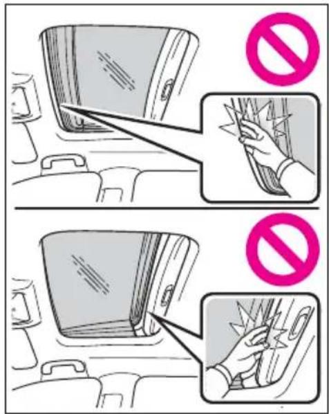
text_image
Diagram illustrating a device safety scenario with no protection symbols and labeled diagrams showing hand positioning and cleaning steps.- When using the wireless remote control or mechanical key and operating the moon roof, operate the moon roof after checking to make sure that there is no possibility of any passenger having any of their body parts caught in the moon roof. Also, do not let a child operate moon roof by the wireless remote control or mechanical key. It is possible for children and other passengers to get caught in the moon roof.
- When exiting the vehicle, turn the power switch to OFF, carry the key and exit the vehicle along with the child. There may be accidental operation, due to mischief, etc., that may possibly lead to an accident.
■Jam protection function
●Never use any part of your body to intentionally activate the jam protection function.
The jam protection function may not work if something gets caught just before the moon roof is fully closed. Also, the jam protection function is not designed to operate while the switch is being pressed. Take care so that your fingers, etc. do not get caught.
Panoramic moon roof\*
*: If equipped
Use the overhead switches to operate the panoramic moon roof and electronic sunshade.
Operating the electronic sunshade and panoramic moon roof
■ Opening and closing the electronic sunshade
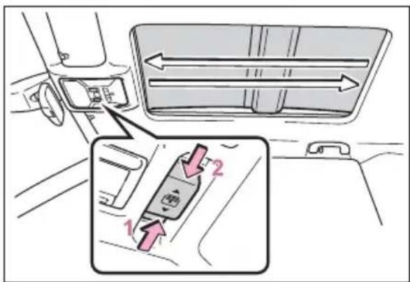
text_image
Diagram showing car interior control panel with directional arrows and labeled parts 1 and 21 Opens the electronic sun-shade*
Slide and hold the switch backward. The electronic sunshade will fully open automatically.
2 Closes the electronic sun-shade*
Slide and hold the switch forward. The electronic sunshade will fully close automatically.
If the panoramic moon roof is not fully closed, it will close fully before the electronic sunshade closes.
*: Quickly slide and release the

switch in either direction to stop the electronic sunshade partway.
■Tilting the panoramic moon roof up and down
Press the switch to tilt the
panoramic moon roof up.*
When the panoramic moon roof is tilted up, the electronic sunshade will open to the half-open position of the roof.
*: Lightly press the switch again to stop the panoramic moon roof partway.
Press and hold the switch to tilt the panoramic moon roof down.
The panoramic moon roof can be tilted down only when it is in the tilt-up position.
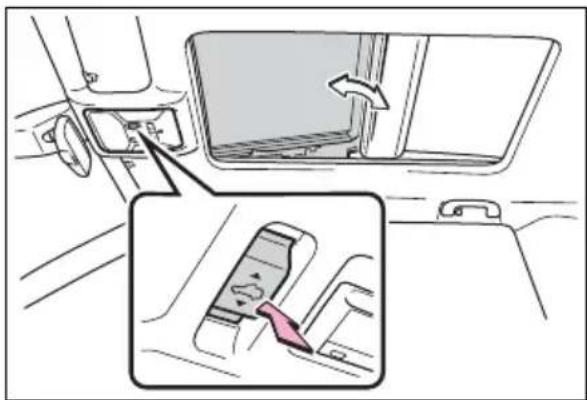
text_image
Diagram showing car interior and dashboard shift with labeled components and directional arrow■ Opening and closing the panoramic moon roof
Opens the panoramic moon roof*
Slide and hold the switch
backward. The panoramic moon roof and electronic sunshade will open automatically.
The panoramic moon roof can be opened from the tilt-up position.
*: Quickly slide and release the
switch in either direction to stop the panoramic moon roof partway.
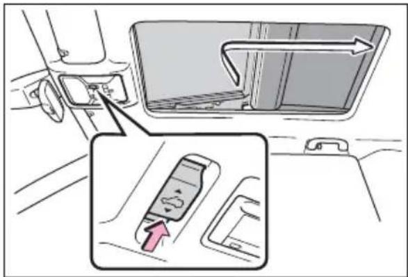
text_image
Diagram showing car seatbelt adjustment with directional arrow and magnified view of seatbelt componentCloses the panoramic moon roof
Slide and hold the switch forward. The panoramic moon roof will fully close automatically.
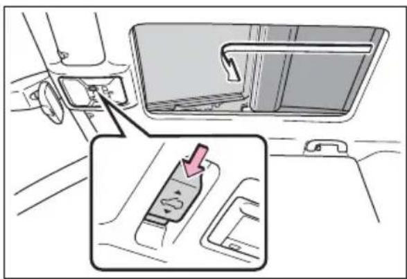
text_image
Diagram showing car interior and seat assembly with a highlighted component and directional arrow indicating movement■The panoramic moon roof can be operated when
The power switch is in ON.
■Operating the panoramic moon roof after turning the hybrid system off
The panoramic moon roof and electronic sunshade can be operated for approximately 45 seconds after the power switch is turned to ACC or OFF. They cannot, however, be operated once either front door is opened.
Jam protection function
If an object is detected between the panoramic moon roof and the frame in the following situations, travel is stopped and the panoramic moon roof opens slightly.
●The panoramic moon roof is closing or tilting down.
●The electronic sunshade is closing.
■ Closing both the panoramic moon roof and electronic sun-shade
Slide the switch forward.
The electronic sunshade will close to the half-open position and pause. The panoramic moon roof will then fully close. Then the electronic sun-shade will fully close.
■ Door lock linked panoramic moon roof operation
●The panoramic moon roof can be opened and closed using the mechanical key.* (→P.670)
●The panoramic moon roof can be opened using the wireless remote control. ^* (→P.127)
● Vehicles with alarm: The alarm may be triggered if the alarm is set and the panoramic moon roof is closed using the door lock linked panoramic moon roof operation function. (→P.84)
*: These settings must be customized at your Toyota dealer.
■When the panoramic moon roof or electronic sunshade does not close normally
Perform the following procedure:
1 Stop the vehicle.
2 Turn the power switch to ON.
3 Slide and hold the switch
or switch forward. Continue sliding and holding the switch for approximately 10 seconds after the panoramic moon roof or electronic sunshade closes and reopens. The panoramic moon roof and electronic sunshade will start to close.*
4 Check that the panoramic moon roof and electronic sunshade are fully closed and release the switch.
*: If the switch is released at the incorrect time, the procedure will have to be performed again from the beginning.
If the panoramic moon roof or electronic sunshade does not fully close even after performing the above procedure correctly, have the vehicle inspected by your Toyota dealer.
■Panoramic moon roof open reminder function
A buzzer sounds and a message is shown on the multi-information display when the power switch is turned to OFF and the driver's door is opened with the panoramic moon roof open.
Customization
Settings (e.g. linked door lock operation) can be changed. (Customizable features: →P.712)

WARNING
Observe the following precautions.
Failure to do so may result in death or serious injury.
■ Opening and closing the electronic sunshade
- Check to make sure that all passengers do not have any part of their body in a position where it could be caught when the electronic sunshade is being operated.
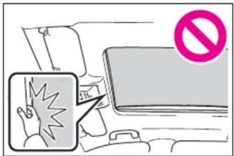
text_image
Illustration showing a hand holding a phone with a 'No' symbol, next to an icon of a person falling into the phone.- Do not let a child operate the electronic sunshade. Closing the electronic sunshade on someone can cause death or serious injury.
■ Opening the panoramic moon roof
- Do not allow any passengers to put their hands or head outside the vehicle while it is moving.
- Do not sit on top of the panoramic moon roof.
■ Opening and closing the panoramic moon roof
The driver is responsible for panoramic moon roof opening and closing operations. In order to prevent accidental operation, especially by a child, do not let a child operate the panoramic moon roof. It is possible for children and other passengers to have body parts caught in the panoramic moon roof.

WARNING
- Check to make sure that all passengers do not have any part of their body in a position where it could be caught when the panoramic moon roof is being operated.
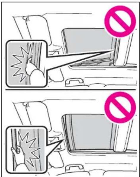
text_image
Illustration showing two scenarios of a person experiencing a collision or explosion, with one scenario marked by a 'no' symbol and the other by a broken-out device.- When using the wireless remote control or mechanical key and operating the panoramic moon roof, operate the panoramic moon roof after checking to make sure that there is no possibility of any passenger having any of their body parts caught in the panoramic moon roof. Also, do not let a child operate panoramic moon roof by the wireless remote control or mechanical key. It is possible for children and other passengers to get caught in the panoramic moon roof.
- When exiting the vehicle, turn the power switch to OFF, carry the key and exit the vehicle along with the child. There may be accidental operation, due to mischief, etc., that may possibly lead to an accident.
Jam protection function
●Never use any part of your body to intentionally activate the jam protection function.
●The jam protection function may not work if something gets caught just before the panoramic moon roof or electronic sunshade is fully closed. Also, the jam protection function is not designed to operate while the switch is being pressed. Take care so that your fingers, etc. do not get caught.
■To prevent burns or injuries
Do not touch the area between the underside of the panoramic moon roof and the electronic sun-shade. Your hand may get caught and you could injure yourself. Also, if the vehicle is left in direct sunlight for a long time, the underside of the panoramic moon roof could become very hot and could cause burns.

NOTICE
■To prevent damage to the panoramic moon roof
Before opening the panoramic moon roof, make sure that there are no foreign objects, such as stones or ice, around the opening.
- Do not hit the surface or edge of the panoramic moon roof with hard objects.
■After the vehicle has been washed or rained on
Before opening the panoramic moon roof, wipe any water off the panoramic moon roof. Otherwise, water may enter the cabin when the panoramic moon roof is opened.
4-1. Before driving
Driving the vehicle..... 189
Cargo and luggage ..... 196
Vehicle load limits ..... 199
Trailer towing 200
Dinghy towing 209
4-2. Driving procedures
Power (ignition) switch (vehicles without smart key system).... 210
Power (ignition) switch (vehicles with smart key system).... 212
EV drive mode ...... 217
Hybrid transmission .... 219
Turn signal lever ...... 223
Parking brake...... 224
Brake Hold 227
4-3. Operating the lights and wipers
Headlight switch...... 229
AHB (Automatic High Beam).... 232
Fog light switch ...... 235
Windshield wipers and washer.... 236
Rear window wiper and washer.... 239
4-4. Refueling
Opening the fuel tank cap 241
4-5. Using the driving support systems
Toyota Safety Sense 2.0 244
PCS (Pre-Collision System) 250
LTA (Lane Tracing Assist) 258
RSA (Road Sign Assist) 268
Dynamic radar cruise control with full-speed range 271
BSM (Blind Spot Monitor) 282
Intuitive parking assist. 291
PKSB (Parking Support Brake).... 298
Parking Support Brake function (static objects) .... 303
Parking Support Brake function (rear-crossing vehicles).... 309
Rear view monitor system 313
Toyota parking assist moni- tor 321
Panoramic view monitor 334
Driving mode select switch 366
Trail Mode 367
Driving assist systems. 369
4-6. Driving tips
Hybrid vehicle driving tips 376
Winter driving tips ..... 378
Utility vehicle precautions 381
Driving the vehicle
The following procedures should be observed to ensure safe driving:
Driving procedure
■Starting the hybrid system
→P.210, 212
Driving
1 With the brake pedal depressed, shift the shift lever to D. ( P.219)
2 Release the parking brake. (→P.224)
If the parking brake is in automatic mode, the parking brake is released automatically when shifting the shift lever to any position other than P. ( P.224)
3 Gradually release the brake pedal and gently depress the accelerator pedal to accelerate the vehicle.
■Stopping
1 With the shift lever in D, depress the brake pedal.
2 If necessary, set the parking brake. ( P.224)
If the vehicle is to be stopped for an extended period of time, shift the shift lever to P. ( P.219)
■Parking the vehicle
1 With the shift lever in D, depress the brake pedal.
2 Set the parking brake ( P.224), and shift the shift lever to P ( P.219).
3 Turn the power switch to OFF to stop the hybrid system.
4 Lock the door, making sure that you have the key on your person.
If parking on a hill, block the wheels as needed.
■ Starting off on a steep uphill
1 With the brake pedal depressed, shift the shift lever to D. ( P.219)
2 Pull the parking brake switch and parking brake is set manually. (→P.224)
3 Release the brake pedal and gently depress the accelerator pedal to accelerate the vehicle.
Parking brake automatic release function ( P.225)
■When starting off on a uphill
The hill-start assist control will activate. ( P.369)
For fuel-efficient driving
Keep in mind that hybrid vehicles are similar to conventional vehicles, and it is necessary to refrain from activities such as sudden acceleration, etc. Refer to “Hybrid vehicle driving tips”. (→P.376)
■Driving in the rain
- Drive carefully when it is raining, because visibility will be reduced, the windows may become fogged-up, and the road could be slip-
pery.
●Drive carefully when it starts to rain, as the road surface could be especially slippery.
●Refrain from high speeds when driving on an expressway in the rain, because there may be a layer of water between the tires and the road surface, preventing the steering and brakes from operating properly.
■ ECO Accelerator Guidance ( P.105)
It is easier to drive in an Eco-friendly manner by driving while referring to the ECO Accelerator Guidance display. Also, by using the ECO Accelerator Guidance it is easier to increase the “Eco Score” evaluation.
- When starting off: While staying within the ECO Accelerator Guidance range, gradually depress the accelerator pedal and accelerate to the desired speed. If excessive acceleration is avoided, the “Start” score will increase.
- When driving: After accelerating to the desired speed, release the accelerator pedal and drive at a stable speed within the ECO Accelerator Guidance range. By keeping the vehicle within the ECO Accelerator Guidance range, the “Cruise” score will increase.
- When stopping: When stopping the vehicle, early releasing the accelerator pedal will cause the “Stop” score to increase.
■Restraining the hybrid system output (Brake Override System)
- When the accelerator and brake pedals are depressed at the same time, the hybrid system output may be restrained.
●A warning message is displayed on the multi-information display while the system is operating.
$$ (\rightarrow \mathrm{P}. 6 4 8) $$
■Restraining sudden start (Drive-Start Control)
- When the following unusual operation is performed, the hybrid system output may be restrained.
- When the shift lever is shifted from R to D, D to R, N to R, P to D ^ , or P to R ^ (D includes S) with the accelerator pedal depressed, a warning message appears on the multi-information display. If a warning message is shown on the multi-information display, read the message and follow the instructions.
- When the accelerator pedal is depressed too much while the vehicle is in reverse.
*: Depending on the situation, the shift lever may not be changed.
●While Drive-Start Control is being activated, your vehicle may have trouble escaping from the mud or fresh snow. In such case, deactivate TRAC (→P.370) to cancel Drive-Start Control so that the vehicle may be able to escape from the mud or fresh snow.
●Drive-Start Control does not work when Trail Mode is turned on.
■Breaking in your new Toyota
To extend the life of the vehicle, observing the following precautions is recommended:
●For the first 200 miles (300 km): Avoid sudden stops.
●For the first 500 miles (800 km): Do not tow a trailer.
●For the first 600 miles (1000 km):
- Do not drive at extremely high speeds.
- Avoid sudden acceleration.
- Do not drive continuously in low gears.
- Do not drive at a constant speed for extended periods.
■ Operating your vehicle in a foreign country
Comply with the relevant vehicle registration laws and confirm the availability of the correct fuel. ( P.685)

WARNING
Observe the following precautions.
Failure to do so may result in death or serious injury.
■When starting the vehicle
Always keep your foot on the brake pedal while stopped with the "READY" indicator is illuminated. This prevents the vehicle from creeping.
■When driving the vehicle
- Do not drive if you are unfamiliar with the location of the brake and accelerator pedals to avoid depressing the wrong pedal.
- Accidentally depressing the accelerator pedal instead of the brake pedal will result in sudden acceleration that may lead to an accident.
- When backing up, you may twist your body around, leading to a difficulty in operating the pedals. Make sure to operate the pedals properly.
- Make sure to keep a correct driving posture even when moving the vehicle only slightly. This allows you to depress the brake and accelerator pedals properly.
- Depress the brake pedal using your right foot. Depressing the brake pedal using your left foot may delay response in an emergency, resulting in an accident.
The driver should pay extra attention to pedestrians when the vehicle is powered only by the electric motor (traction motor). As there is no engine noise, the pedestrians may mis-judge the vehicle's movement. Even though the vehicle is equipped with the vehicle proximity notification system, drive with care as pedestrians in the vicinity may still not notice the vehicle if the surrounding area is noisy.
- Do not drive the vehicle over or stop the vehicle near flammable materials such as leaves, paper or rags.
The exhaust system and exhaust gases can be extremely hot. These hot parts may cause a fire if there is any flammable material nearby.
During normal driving, do not turn off the hybrid system. Turning the hybrid system off while driving will not cause loss of steering or braking control, however, power assist to the steering will be lost. This will make it more difficult to steer smoothly, so you should pull over and stop the vehicle as soon as it is safe to do so. In the event of an emergency, such as if it becomes impossible to stop the vehicle in the normal way: P.635
- Use engine braking (downshift) to maintain a safe speed when driving down a steep hill. Using the brakes continuously may cause the brakes to overheat and lose effectiveness. ( P.219)

WARNING
- Do not adjust the position of the steering wheel, the seat, or the inside or outside rear view mirrors while driving. Doing so may result in a loss of vehicle control.
● Always check that all passengers' arms, head or other parts of their body are not outside the vehicle.
- Do not drive in excess of the speed limit. Even if the legal speed limit permits it, do not drive over 85 mph (140 km/h) unless your vehicle has high-speed capability tires. Driving over 85 mph (140 km/h) may result in tire failure, loss of control and possible injury. Be sure to consult a tire dealer to determine whether the tires on your vehicle are high-speed capability tires or not before driving at such speeds.
■When driving on slippery road surfaces
● Sudden braking, acceleration and steering may cause tire slippage and reduce your ability to control the vehicle.
● Sudden acceleration, engine braking due to shifting, or changes in engine speed could cause the vehicle to skid.
● After driving through a puddle, lightly depress the brake pedal to make sure that the brakes are functioning properly. Wet brake pads may prevent the brakes from functioning properly. If the brakes on only one side are wet and not functioning properly, steering control may be affected.
■When shifting the shift lever
- Do not let the vehicle roll backward while a forward driving position is selected, or roll forward while the shift lever is in R. Doing so may result in an accident or damage to the vehicle.
- Do not shift the shift lever to P while the vehicle is moving. Doing so can damage the transmission and may result in a loss of vehicle control.
- Do not shift the shift lever to R while the vehicle is moving forward. Doing so can damage the transmission and may result in a loss of vehicle control.
- Do not shift the shift lever to a driving position while the vehicle is moving backward. Doing so can damage the transmission and may result in a loss of vehicle control.
- Moving the shift lever to N while the vehicle is moving will disengage the hybrid system. Engine braking is not available with the hybrid system disengaged.
- Be careful not to shift the shift lever with the accelerator pedal depressed. Shifting the shift lever to a gear other than P or N may lead to unexpected rapid acceleration of the vehicle that may cause an accident and result in death or serious injury. Doing so can damage the transmission and may result in a loss of vehicle control.

WARNING
■If you hear a squealing or scraping noise (brake pad wear limit indicators)
Have the brake pads checked and replaced by your Toyota dealer as soon as possible.
Rotor damage may result if the pads are not replaced when needed.
It is dangerous to drive the vehicle when the wear limits of the brake pads and/or those of the brake discs are exceeded.
■When the vehicle is stopped
- Do not depress the accelerator pedal unnecessarily.
If the vehicle is in any gear other than P or N, the vehicle may accelerate suddenly and unexpectedly, causing an accident.
In order to prevent accidents due to the vehicle rolling away, always keep depressing the brake pedal while stopped with the "READY" indicator is illuminated, and apply the parking brake as necessary.
- If the vehicle is stopped on an incline, in order to prevent accidents caused by the vehicle rolling forward or backward, always depress the brake pedal and securely apply the parking brake as needed.
● Avoid revving or racing the engine.
Running the engine at high speed while the vehicle is stopped may cause the exhaust system to overheat, which could result in a fire if combustible material is nearby.
■When the vehicle is parked
- Do not leave glasses, cigarette lighters, spray cans, or soft drink cans in the vehicle when it is in the sun.
Doing so may result in the following:
• Gas may leak from a cigarette lighter or spray can, and may lead to a fire.
- The temperature inside the vehicle may cause the plastic lenses and plastic material of glasses to deform or crack.
- Soft drink cans may fracture, causing the contents to spray over the interior of the vehicle, and may also cause a short circuit in the vehicle's electrical components.
- Do not leave cigarette lighters in the vehicle. If a cigarette lighter is in a place such as the glove box or on the floor, it may be lit accidentally when luggage is loaded or the seat is adjusted, causing a fire.
- Do not attach adhesive discs to the windshield or windows. Do not place containers such as air fresheners on the instrument panel or dashboard. Adhesive discs or containers may act as lenses, causing a fire in the vehicle.
- Do not leave a door or window open if the curved glass is coated with a metallized film such as a silver-colored one. Reflected sunlight may cause the glass to act as a lens, causing a fire.

WARNING
● Always apply the parking brake, shift the shift lever to P, stop the hybrid system and lock the vehicle.
Do not leave the vehicle unattended while the "READY" indicator is illuminated.
If the vehicle is parked with the shift lever in P but the parking brake is not set, the vehicle may start to move, possibly leading to an accident.
- Do not touch the exhaust pipes while the “READY” indicator is illuminated or immediately after turning the hybrid system off. Doing so may cause burns.
■When taking a nap in the vehicle
Always turn the hybrid system off. Otherwise, if you accidentally move the shift lever or depress the accelerator pedal, this could cause an accident or fire due to hybrid system overheating. Additionally, if the vehicle is parked in a poorly ventilated area, exhaust gases may collect and enter the vehicle, leading to death or a serious health hazard.
When braking
-
When the brakes are wet, drive more cautiously.
Braking distance increases when the brakes are wet, and this may cause one side of the vehicle to brake differently than the other side. Also, the parking brake may not securely hold the vehicle. -
If the electronically controlled brake system does not operate, do not follow other vehicles closely and avoid hills or sharp turns that require braking. In this case, braking is still possible, but the brake pedal should be depressed more firmly than usual. Also, the braking distance will increase. Have your brakes fixed immediately.
●The brake system consists of 2 or more individual hydraulic systems; if one of the systems fails, the other will still operate. In this case, the brake pedal should be depressed more firmly than usual and the braking distance will increase. Have your brakes fixed immediately.
■If the vehicle becomes stuck
Do not spin the wheels excessively when any of the tires is up in the air, or the vehicle is stuck in sand, mud, etc. This may damage the driveline components or propel the vehicle forward or backward, causing an accident.

NOTICE
■When driving the vehicle
- Do not depress the accelerator and brake pedals at the same time during driving, as this may restrain the hybrid system output.
- Do not use the accelerator pedal or depress the accelerator and brake pedals at the same time to hold the vehicle on a hill.

NOTICE
■ Avoiding damage to vehicle parts
- Do not turn the steering wheel fully in either direction and hold it there for an extended period of time.
Doing so may damage the power steering motor.
- When driving over bumps in the road, drive as slowly as possible to avoid damaging the wheels, underside of the vehicle, etc.
■If you get a flat tire while driving
A flat or damaged tire may cause the following situations.
- It may be difficult to control your vehicle.
●The vehicle will make abnormal sounds or vibrations.
●The vehicle will lean abnormally.
Hold the steering wheel firmly and gradually depress the brake pedal to slow down the vehicle.
Information on what to do in case of a flat tire ( P.658)
■When encountering flooded roads
Do not drive on a road that has flooded after heavy rain, etc. Doing so may cause the following serious damage to the vehicle:
Engine stalling
●Short in electrical components
●Engine damage caused by water immersion
In the event that you drive on a flooded road and the vehicle is flooded, be sure to have your Toyota dealer check the following:
●Brake function
● Changes in quantity and quality of oil and fluid used for the engine, hybrid transaxle (front and rear), etc.
● Lubricant condition for the bearings and suspension joints (where possible), and the function of all joints, bearings, etc.
■When parking the vehicle
Always set the parking brake, and shift the shift lever to P. Failure to do so may cause the vehicle to move or the vehicle may accelerate suddenly if the accelerator pedal is accidentally depressed.
Cargo and luggage
Take notice of the following information about storage precautions, cargo capacity and load.

WARNING
■Things that must not be carried in the luggage compartment
The following things may cause a fire if loaded in the luggage compartment:
●Receptacles containing gasoline
Aerosol cans
■Storage precautions
Observe the following precautions.
Failure to do so may prevent the pedals from being depressed properly, may block the driver's vision, or may result in items hitting the driver or passengers, possibly causing an accident.
● Stow cargo and luggage in the luggage compartment whenever possible.
- Do not stack anything in the luggage compartment higher than the seatbacks.
- Do not place cargo or luggage in or on the following locations.
• At the feet of the driver
- On the front passenger or rear seats (when stacking items)
- On the luggage cover (if equipped)
• On the instrument panel
- On the dashboard
- Secure all items in the occupant compartment.
- When you fold down the rear seats, long items should not be placed directly behind the front seats.
●Never allow anyone to ride in the luggage compartment. It is not designed for passengers. They should ride in their seats with their seat belts properly fastened. Otherwise, they are much more likely to suffer death or serious bodily injury, in the event of sudden braking, sudden swerving or an accident.
Capacity and distribution
Cargo capacity depends on the total weight of the occupants.
(Cargo capacity) = (Total load capacity) - (Total weight of occupants)
Steps for Determining Correct Load Limit —
(1) Locate the statement "The combined weight of occupants and cargo should never exceed XXX kg or XXX lbs." on your vehicle's placard.
(2) Determine the combined weight of the driver and passengers that will be riding in your vehicle.
(3) Subtract the combined weight of the driver and passengers from XXX kg or XXX lbs.
(4) The resulting figure equals the available amount of cargo and luggage load capacity.
For example, if the “XXX” amount equals 1400 lbs. and there will be five 150 lb passengers in your vehicle, the amount of available cargo and luggage load capacity is 650 lbs. (1400 - 750 (5 × 150) = 650 lbs.)
(5) Determine the combined weight of luggage and cargo being loaded on the vehicle. That weight may not safely exceed the available cargo and luggage load capacity calculated in Step 4.
(6) If your vehicle will be towing a trailer, load from your trailer will be transferred to your vehicle. Consult this manual to determine how this reduces the available cargo and luggage load capacity of your vehicle. (→P.199)

WARNING
■Capacity and distribution
- Do not exceed the maximum axle weight rating or the total vehicle weight rating.
Even if the total load of occupant' weight and the cargo load is less than the total load capacity, do not apply the load unevenly. Improper loading may cause deterioration of steering or braking control which may cause death or serious injury.
Calculation formula for your vehicle
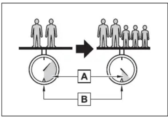
flowchart
graph TD
    A["Human Group 1"] --> B["Human Group 2"]
    B --> C["Output"]
    D["Human Group 3"] --> E["Human Group 4"]
    E --> F["Output"]
    G["Human Group 5"] --> H["Human Group 6"]
    H --> I["Output"]
    J["Human Group 7"] --> K["Human Group 8"]
    K --> L["Output"]
    M["Human Group 9"] --> N["Human Group 10"]
    N --> O["Output"]
A Cargo capacity
B Total load capacity (vehicle capacity weight) ( P.684)
When 2 people with the combined weight of A lb. (kg) are rid-ing in your vehicle, which has a total load capacity (vehicle capacity weight) of B lb. (kg), the available amount of cargo and luggage load capacity will be C lb. (kg) as follows:
B^2 lb. (kg) - A ^1 lb. (kg) = C ^*3 lb. (kg)
*1:A = Weight of people
^2 :B = Total load capacity
^3 :C = Available cargo and luggage load
In this condition, if 3 more passengers with the combined weight of D lb. (kg) get on, the available cargo and luggage load will be reduced E lb. (kg) as follows:
C lb. (kg) - D ^4 lb. (kg) = E ^5 lb. (kg)
*4:D = Additional weight of people
^*5 :E = Available cargo and luggage
load
As shown in the example above, if the number of occupants increases, the cargo and luggage load will be reduced by an amount that equals the increased weight due to the additional occupants. In other words, if an increase in the number of occupants causes an excess of the total load capacity (combined weight of occupants plus cargo and luggage load), you must reduce the cargo and luggage on your vehicle.
- If driving for a long distance, on rough roads, or at high speeds, stop the vehicle now and then during the trip to make sure the cargo remains in its place.
- Do not exceed 176.4 lb. (80 kg) cargo weight on the roof luggage carrier.

NOTICE
■When loading cargo on the roof luggage carrier (if equipped)
Be careful not to scratch the surface of the moon roof (if equipped) or the panoramic moon roof (if equipped).

WARNING
■When loading cargo on the roof luggage carrier (if equipped)
Observe the following precautions:
- Place the cargo so that its weight is distributed evenly between the front and rear axles.
- If loading long or wide cargo, never exceed the vehicle overall length or width. (→P.684)
●Before driving, make sure the cargo is securely fastened on the roof luggage carrier. - Loading cargo on the roof luggage carrier will make the center of gravity of the vehicle higher. Avoid high speeds, sudden starts, sharp turns, sudden braking or abrupt maneuvers, otherwise it may result in loss of control or vehicle rollover due to failure to operate this vehicle correctly and result in death or serious injury.
Vehicle load limits
Vehicle load limits include total load capacity, seating capacity, TWR (Trailer Weight Rating) and cargo capacity.
● Total load capacity (vehicle capacity weight): →P.684
Total load capacity means the combined weight of occupants, cargo and luggage.
● Seating capacity: →P.684
Seating capacity means the maximum number of occupants whose estimated average weight is 150 lb. (68 kg) per person.
● TWR (Trailer Weight Rating): →P.204, 684
TWR means the maximum gross trailer weight (trailer weight plus its cargo weight) that your vehicle is able to tow.
- Cargo capacity
Cargo capacity may increase or decrease depending on the weight and the number of occupants.
■ Total load capacity and seating capacity
These details are also described on the tire and loading information label. ( P.605)

WARNING
■Overloading the vehicle
Do not overload the vehicle. It may not only cause damage to the tires, but also degrade steering and braking ability, resulting in an accident.
Trailer towing
Your vehicle is designed primarily as a passenger-and-load-carrying vehicle. Towing a trailer can have an adverse impact on handling, performance, braking, durability, and fuel consumption. For your safety and the safety of others, you must not overload your vehicle or trailer. You must also ensure that you are using appropriate towing equipment, that the towing equipment has been installed correctly and used properly, and that you employ the requisite driving habits.
Vehicle-trailer stability and braking performance are affected by trailer stability, brake performance and setting, trailer brakes, the hitch and hitch systems (if equipped).
To tow a trailer safely, use extreme care and drive the vehicle in accordance with your trailer's characteristics and operating conditions.
Toyota warranties do not apply to damage or malfunction caused by towing a trailer for commercial purposes.
Contact your Toyota dealer for further information about additional requirements such as a towing kit, etc.
Before towing
Check that the following conditions are met:
- Ensure that your vehicle's tires are properly inflated. (→P.690)
- Trailer tires are inflated according to the trailer manufacturer's recommendation.
● All trailer lights work as required by law.
● All lights work each time you connect them.
●The trailer ball is set at the proper height for the coupler on the trailer.
●The trailer is level when it is hitched. Do not drive if the trailer is not level, and check for improper tongue weight, overloading, worn suspension, or other possible causes.
●The trailer cargo is securely loaded.
●The rear view mirrors conform to all applicable federal, state/provincial or local regulations. If they do not, install rear view mirrors appropriate for towing purposes.

WARNING
■Trailer towing precautions
To tow a trailer safely, use extreme care and drive the vehicle in accordance with the trailer's characteristics and operating conditions. Failure to do so could cause an accident resulting in death or serious injury. Vehicle stability and braking performance are affected by trailer stability, brake setting and performance, and the hitch. Your vehicle will handle differently when towing a trailer.
■To avoid accident or injury
●Do not exceed the TWR, unbraked TWR, GCWR, GVWR or GAWR.
- Adjust the tongue weight within the appropriate range. Place heavier loads as close to the trailer axle as possible.
- Do not exceed 65 mph (104 km/h), the posted towing speed limit or the speed limit for your trailer as set forth in your trailer owner's manual, whichever is lowest. Slow down sufficiently before making a turn, in cross winds, on wet or slippery surface, etc. to help avoid an accident. If you experience a vehicle-trailer instability from reducing a certain speed, slow down and make sure you keep your vehicle speed under the speed of which you experience the instability.
- Do not make jerky, abrupt or sharp turns.
- Do not apply the brakes suddenly as you may skid, resulting in jackknifing and loss of vehicle control. This is especially true on wet or slippery surfaces.
- Do not exceed the trailer hitch assembly weight, gross vehicle weight, gross axle weight and trailer tongue weight capacities.
- Do not use dynamic radar cruise control with full-speed range when towing.
● Slow down and downshift before descending steep or long downhill grades. Do not make sudden downshifts while descending steep or long downhill grades.
● Vehicle-trailer instability is more likely on steep long downhills. Before descending steep or long downhill grades, slow down and downshift. Do not make sudden downshifts when descending steep or long downhill grades. Avoid holding the brake pedal down too long or applying the brakes too frequently. This could cause the brakes to overheat and result in reduced braking efficiency.
- Do not tow a trailer when the compact spare tire is installed on your vehicle.
■When towing a trailer
Toyota recommends trailers with brakes that conform to any applicable federal and state/provincial regulations.
- If the gross trailer weight exceeds unbraked TWR, trailer brakes are required. Toyota recommends trailers with brakes that conform to all applicable federal and state/provincial regulations.
- Never tap into your vehicle's hydraulic system, as this will lower the vehicle's braking effectiveness.

WARNING
● Never tow a trailer without using a safety chain securely attached to both the trailer and the vehicle. If damage occurs to the coupling unit or hitch ball, there is danger of the trailer wandering into another lane.
Towing related terms
■GCWR (Gross Combination Weight Rating)
The maximum allowable gross combination weight. The gross combination weight is the sum of the total vehicle weight (including the occupants, cargo and any optional equipment installed on the vehicle) and the weight of the trailer being towed (including the cargo in the trailer).
natural_image
Line drawing of a car on a platform with a speedometer, no text or symbols present■GVWR (Gross Vehicle Weight Rating)
The maximum allowable gross vehicle weight. The gross vehicle weight is the total weight of the vehicle. When towing a trailer, it is the sum of the vehicle weight (including the occupants, cargo and any optional
equipment installed on the vehicle) and the tongue weight.
natural_image
Line drawing of a car on a platform with a speedometer and cargo container nearby (no text or symbols)■ GAWR (Gross Axle Weight Rating)
The maximum allowable gross axle weight. The gross axle weight is the load placed on each axle (front and rear).
text_image
A BA Front GAWR
B Rear GAWR
■TWR (Trailer Weight Rating)
The maximum allowable gross trailer weight. The gross trailer weight is the sum of the trailer weight and the weight of the cargo in the trailer.
TWR is calculated assuming
base vehicle with one driver, one front passenger, hitch and hitch systems (if required).
Additional optional equipment, passengers and cargo in the vehicle will reduce the trailer weight rating so as not to exceed GCWR, GVWR and GAWR.
natural_image
Simple line drawing of a balance scale with a cart and pointer (no text or symbols)A (With brakes)
■ Unbraked TWR (Unbraked Trailer Weight Rating)
The trailer weight rating for towing a trailer without a trailer service brake system.
natural_image
Simple line drawing of a balance scale with a cart and pointer, no text or symbols presentA (Without brakes)
■Tongue Weight
The load placed on the trailer hitch ball. ( P.204)
natural_image
Simple line drawing of a mechanical device with a dial indicator and a cart on a surface (no text or symbols)Weight limits
● The gross trailer weight must never exceed 1750 lb. (795 kg).
- The gross combination weight must never exceed 6670 lb. (3025 kg).
- The gross vehicle weight must never exceed the GVWR indicated on the Certification Regulation Label.
- The gross axle weight on each axle must never exceed the GAWR indicated on the Certification Regulation Label.
natural_image
Diagram of a car seatbelt buckle with a black arrow pointing to the seat (no text or symbols present)- If the gross trailer weight is over the unbraked TWR, trailer service brakes are required.
GCWR, TWR and Unbraked TWR
Confirm that the gross trailer weight, gross combination weight, gross vehicle weight, gross axle weight and tongue weight are all within the limits.
GCWR\*
6670 lb. (3025 kg)
*: This model meets the tow-vehicle trailering requirement of SAE International per SAE J2807.
TWR\*
1750 lb. (795 kg)
*: This model meets the tow-vehicle trailering requirement of SAE International per SAE J2807.
■Unbraked TWR \*
1000 lb. (450 kg)
*: This model meets the tow-vehicle trailering requirement of SAE International per SAE J2807.
Trailer Tongue Weight
● A recommended tongue weight varies in accordance with the types of trailers or towing as described below.
- To ensure the recommended values shown below, the trailer must be loaded by referring to the following instructions.
- Tongue Weight
The gross trailer weight should be
distributed so that the tongue weight is 9% to 11%.
(Tongue weight /Gross trailer weight x 100 = 9% to 11%)
text_image
A BA Gross trailer weight
B Tongue weight
The gross trailer weight, gross axle weight and tongue weight can be measured with platform scales found at a highway weighing station, building supply company, trucking company, junk yard, etc.
Hitch
Trailer hitch assemblies have different weight capacities.
Toyota recommends the use of Toyota hitch/bracket for your vehicle. For details, contact your Toyota dealer.
- If you wish to install a trailer hitch, contact your Toyota dealer.
- Use only a hitch that conforms to the gross trailer weight requirement of your vehicle.
● Follow the directions supplied
by the hitch manufacturer.
● Lubricate the hitch ball with a light coating of grease.
- Remove the hitch ball whenever you are not towing a trailer. Remove the trailer hitch if you do not need it. After removing the hitch, seal any mounting holes in the vehicle body to prevent entry of any substances into the vehicle.

WARNING
Hitch
Trailer hitch assemblies have different weight capacities established by the hitch manufacturer. Even though the vehicle may be physically capable of towing a higher weight, the operator must determine the maximum weight rating of the particular hitch assembly and never exceed the maximum weight rating specified for the trailer-hitch. Exceeding the maximum weight rating set by the trailer-hitch manufacturer can cause an accident resulting in death or serious personal injuries.

NOTICE
■When installing a trailer hitch
Use only the position recommended by your Toyota dealer. Do not install the trailer hitch on the bumper; this may cause body damage.
Positions for towing hitch receiver and hitch ball
text_image
A BA Weight carrying ball position: 43.3 in. (1100 mm)
B Hitch receiver pin hole position: 38.1 in. (969 mm)
■ Matching trailer ball height to trailer coupler height
No matter which class of tow hitch applies, for a more safe trailer hookup, the trailer ball setup must be the proper height for the coupler on the trailer.
natural_image
Illustration of a car pulling a large block with a 'no' symbol above, no text or labels present
text_image
A BA Coupler
B Trailer ball
Connecting trailer lights
Please consult your dealer when installing trailer lights, as incorrect installation may cause damage to the vehicle's lights. Please take care to comply with your state's laws when installing trailer lights.

NOTICE
■ Do not directly splice trailer lights
Do not directly splice trailer lights. Directly splicing trailer lights may damage your vehicle's electrical system and cause a malfunction.
Trailer towing tips
Your vehicle will handle differently when towing a trailer. Help to avoid an accident, death or serious injury, keep the following in mind when towing:
- Speed limits for towing a trailer vary by state or province. Do not exceed the posted towing speed limit.
- Toyota recommends that the vehicle-trailer speed limit is 65 mph (104 km/h) on a flat, straight, dry road. Do not exceed this limit, the posted towing speed limit or the speed limit for your trailer as set forth in your trailer owner's manual, whichever is lowest. Instability of the towing vehicle-trailer combination (trailer sway) increases as speed
increases. Exceeding speed limits may cause loss of control.
- Before starting out, check the trailer lights, tires and the vehicle-trailer connections. Recheck after driving a short distance.
● Practice turning, stopping and reversing with the trailer attached in an area away from traffic until you become accustomed to the feel of the vehicle-trailer combination.
- Reversing with a trailer attached is difficult and requires practice. Grip the bottom of the steering wheel and move your hand to the left to move the trailer to the left. Move your hand to the right to move the trailer to right. (This is generally opposite to reversing without a trailer attached.) Avoid sharp or prolonged turning. Have someone guide you when reversing to reduce the risk of an accident.
- As stopping distance is increased when towing a trailer, vehicle-to vehicle distance should be increased. For each 10 mph (16 km/h) of speed, allow at least one vehicle and trailer length.
- Avoid sudden braking as you may skid, resulting in the trailer jackknifing and a loss of
vehicle control. This is especially true on wet or slippery surfaces.
- Avoid jerky starts or sudden acceleration.
- Avoid jerky steering and sharp turns, and slow down before making turn.
- Note that when making a turn, the trailer wheels will be closer than the vehicle wheels to the inside of the turn. Compensate by making a wider than normal turning radius.
- Slow down before making a turn, in cross winds, on wet or slippery surfaces, etc.
Increasing vehicle speed can destabilize the trailer.
● Take care when passing other vehicles. Passing requires considerable distance. After passing a vehicle, do not forget the length of your trailer, and be sure you have plenty of room before changing lanes.
- To maintain engine braking efficiency, when using engine braking, do not use the transmission in D.
- Instability happens more frequently when descending steep or long downhill grades. Before descending, slow down and downshift. Do not make sudden downshifts while descending steep or
long downhill grades.
- Avoid holding the brake pedal down too long or applying the brakes too frequently. This could cause the brakes to overheat and result in reduced braking efficiency.
- Due to the added load of the trailer, your vehicle's hybrid system may overheat on hot days (at temperatures over 85°F [30°C]) when driving up a long or steep grade. If the engine coolant temperature gauge indicates overheating, immediately turn off the air conditioning (if in use), pull your vehicle off the road and stop in a safe spot. (→P.677)
- Always place wheel blocks under both the vehicle's and the trailer's wheels when parking. Apply the parking brake firmly, and put the transmission in P. Avoid parking on a slope, but if unavoidable, do so only after performing the following:
1 Apply the brakes and keep them applied.
2 Have someone place wheel blocks under both the vehicle's and trailer's wheels.
3 When the wheel blocks are in place, release the brakes slowly until the blocks absorb the load.
4 Apply the parking brake firmly.
5 Shift into P and turn off the hybrid system.
- When restarting after parking on a slope:
1 With the transmission in P, start the hybrid system. Be sure to keep the brake pedal depressed.
2 Shift into a forward gear. If reversing, shift into R.
3 If the parking brake is in manual mode, release the parking brake. (→P.224)
4 Release the brake pedal, and slowly pull or back away from the wheel blocks. Stop and apply the brakes.
5 Have someone retrieve the blocks.
Break-in schedule
If your vehicle is new or equipped with any new power train components (such as an engine, transmission, differential or wheel bearing), Toyota recommends that you do not tow a trailer until the vehicle has been driven for over 500 miles (800 km).
After the vehicle has been driven for over 500 miles (800 km), you can start towing. However, for the next 500 miles (800 km), drive the vehicle at a speed of less than 45 mph (72 km/h) when towing a trailer, and avoid full throttle acceleration.
Maintenance
- If you tow a trailer, your vehicle will require more frequent maintenance due to the additional load.
(See "Scheduled Maintenance Guide" or "Owner's Manual Supplement".)
- Retighten the fixing bolts of the towing ball and bracket after approximately 600 miles (1000 km) of trailer towing.
■If trailer sway occurs
One or more factors (crosswinds, passing vehicles, rough roads, etc.) can adversely affect handling of your vehicle and trailer, causing instability.
- If trailer swaying occurs:
- Firmly grip the steering wheel. Steer straight ahead. Do not try to control trailer swaying by turning the steering wheel.
- Begin releasing the accelerator pedal immediately but very gradually to reduce speed. Do not increase speed. Do not apply vehicle brakes.
If you make no extreme correction with the steering or brakes, your vehicle and trailer should stabilize (if enabled, Trailer Sway Control can also help to stabilize the vehicle and trailer.).
●After the trailer swaying has stopped:
- Stop in a safe place. Get all occupants out of the vehicle.
- Check the tires of the vehicle and the trailer.
- Check the load in the trailer. Make sure the load has not shifted.
Make sure the tongue weight is appropriate, if possible.
- Check the load in the vehicle. Make sure the vehicle is not overloaded after occupants get in.
If you cannot find any problems, the speed at which trailer swaying occurred is beyond the limit of your particular vehicle-trailer combination. Drive at a lower speed to prevent instability. Remember that
swaying of the towing vehicle-trailer increases as speed increases.
Dinghy towing
Your vehicle is not designed to be dinghy towed (with 4 wheels on the ground) behind a motor home.
natural_image
Silhouette of a car approaching a parking van with an arrow, next to a pink prohibition symbol (no text present)
NOTICE
■To avoid serious damage to your vehicle
Do not tow your vehicle with 4 wheels on the ground.
■To prevent causing serious damage to the transmission and AWD system
Never tow this vehicle with any of the wheels on the ground. This may cause serious damage to the transmission and AWD system.
text_image
Diagram showing two parking lot scenarios with a car and a no-smoking symbolPower (ignition) switch (vehicles with- out smart key system)
Starting the hybrid sys- tem
1 Pull the parking brake switch to check that the parking brake is set. (→P.224)
The parking brake indicator will come on.
2 Check that the shift lever is in P.
3 Firmly depress the brake pedal.
4 Turn the power switch to START to start the hybrid system.
If the "READY" indicator turns on, the hybrid system will operate normally.
Continue depressing the brake pedal until the "READY" indicator is illuminated.
text_image
READY PUSH5 Check that the "READY" indicator is illuminated.
The vehicle will not move when the "READY" indicator is off.
■If the hybrid system does not start
The immobilizer system may not have been deactivated. (→P.81) Contact your Toyota dealer.
■When the steering lock cannot be released
When starting the hybrid system, the power switch may seem stuck in OFF. To free it, turn the key while turning the steering wheel slightly left and right.
text_image
Diagram illustrating steering wheel and push button mechanism with directional arrows and labels■When the ambient temperature is low, such as during winter driving conditions
- When starting the hybrid system, the flashing time of the "READY" indicator may be long. Leave the vehicle as it is until the "READY" indicator is steady on, as steady means the vehicle is able to move.
- When the hybrid battery (traction battery) is extremely cold (below approximately -22^[-30^] ) under the influence of the outside temperature, it may not be possible to start the hybrid system. In this case, try to start the hybrid system again after the temperature of the hybrid battery increases due to the outside temperature increase etc.
■ Sounds and vibrations specific to a hybrid vehicle
→P.74
If the "READY" indicator does not come on
In the event that the "READY" indicator does not come on even after performing the proper procedures
for starting the vehicle, contact your Toyota dealer immediately.
When "Check Fuel Cap" is displayed on the multi-information display
→P.243
■If the hybrid system is malfunctioning
→P.80

WARNING
■When starting the hybrid system
Always start the hybrid system while sitting in the driver's seat. Do not depress the accelerator pedal while starting the hybrid system under any circumstances. Doing so may cause an accident resulting in death or serious injury.

NOTICE
■When starting the hybrid system
If the hybrid system becomes difficult to start, have your vehicle checked by your Toyota dealer immediately.
Changing power switch modes
text_image
A B C D PUSH ACC STOPA OFF ("LOCK" position)
The steering wheel is locked and the key can be removed. (The key can be removed only when the shift lever is in P.)
B ACC ("ACC" position)
Some electrical components such as the audio system can be used.
C ON ("ON" position)
All electrical components can be used.
D START ("START" position)
For starting the hybrid system.
■Turning the key from ACC to OFF
1 Shift the shift lever to P.
2 Push in the key and turn it to OFF.
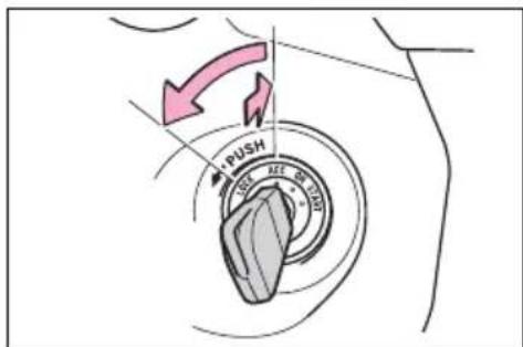
text_image
PUSH LEE■Key reminder function
A buzzer sounds if the driver's door is opened while the power switch is in OFF or ACC to remind you to remove the key.

WARNING
■Caution when driving
Do not turn the power switch to OFF while driving. If, in an emergency and you must turn the hybrid system off while the vehicle is moving, turn the power switch only to ACC to stop the hybrid system. An accident may result if the hybrid system is stopped while driving. (→P.635)

NOTICE
■To prevent 12-volt battery discharge
Do not leave the power switch in ACC or ON mode for long periods of time without the hybrid system on.
Power (ignition) switch (vehicles with smart key system)
Performing the following operations when carrying the electronic key on your person starts the hybrid system or changes power switch modes.
Starting the hybrid sys- tem
1 Pull the parking brake switch to check that the parking brake is set. (→P.224)
The parking brake indicator will come on.
2 Check that the shift lever is set in P.
3 Firmly depress the brake pedal.

and a message will be dis-
played on the multi-information display.
If it is not displayed, the hybrid system cannot be started.
4 Press the power switch shortly and firmly.
When operating the power switch, one short, firm press is enough. It is not necessary to press and hold the switch.
If the "READY" indicator turns on, the hybrid system will operate normally.
Continue depressing the brake pedal until the "READY" indicator is illuminated.
The hybrid system can be started
from any power switch mode.
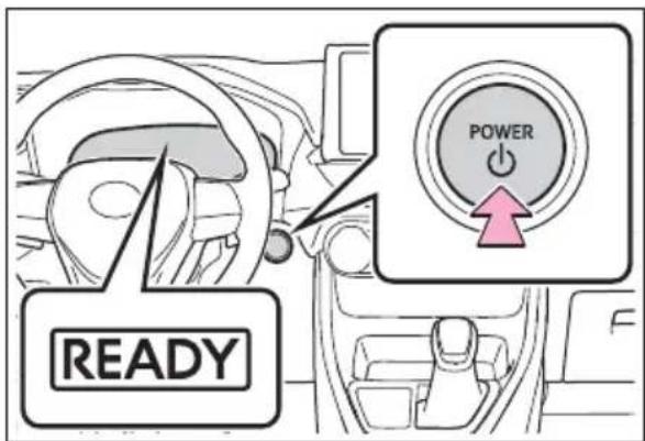
text_image
READY POWER5 Check that the "READY" indicator is illuminated.
The vehicle will not move when the "READY" indicator is off.
■If the hybrid system does not start
●The immobilizer system may not have been deactivated. (→P.81) Contact your Toyota dealer.
- If a message related to start-up is shown on the multi-information display, read the message and follow the instructions.
■When the ambient temperature is low, such as during winter driving conditions
- When starting the hybrid system, the flashing time of the "READY" indicator may be long. Leave the vehicle as it is until the "READY" indicator is steady on, as steady means the vehicle is able to move.
- When the hybrid battery (traction battery) is extremely cold (below approximately -22°F [-30°C]) under the influence of the outside temperature, it may not be possible to start the hybrid system. In this case, try to start the hybrid system again after the temperature of the hybrid battery increases due to the outside temperature increase etc.
■ Sounds and vibrations specific to a hybrid vehicle
→P.74
■If the 12-volt battery is discharged
The hybrid system cannot be started using the smart key system. Refer to P.672to restart the hybrid system.
Electronic key battery depletion →P.120
■Conditions affecting operation →P.148
Note for the entry function →P.149
■Steering lock function
● After turning the power switch to OFF and opening and closing the doors, the steering wheel will be locked due to the steering lock function. Operating the power switch again automatically cancels the steering lock.
- When the steering lock cannot be released, "Push power switch while turning the steering wheel in either direction" will be displayed on the multi-information display. Check that the shift lever is set in P. Press the power switch shortly and firmly while turning the steering wheel left and right.
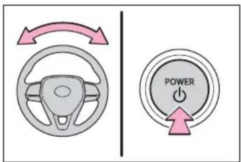
text_image
Diagram showing steering wheel and power button with directional arrows, likely illustrating steering or navigation system.● To prevent the steering lock motor from overheating, the motor may be suspended if the hybrid system is turned on and off repeatedly in a short period of time. In this case, refrain from operating the power switch. After about 10 seconds, the steering lock motor will resume functioning.
If there is a malfunction in the smart key system
If "Smart Key System Malfunction" is displayed on the multi-information display, the system may be malfunctioning. Have the vehicle inspected by your Toyota dealer immediately.
If the "READY" indicator does not come on
In the event that the "READY" indicator does not come on even after performing the proper procedures for starting the vehicle, contact your Toyota dealer immediately.
- When “Check Fuel Cap” is displayed on the multi-information display
→P.243
■If the hybrid system is malfunctioning
→P.80
Electronic key battery
→P.618
■Operation of the power switch
- If the switch is not pressed shortly and firmly, the power switch mode may not change or the hybrid system may not start.
- If attempting to restart the hybrid system immediately after turning the power switch to OFF, the hybrid system may not start in some cases. After turning the power switch to OFF, please wait a few seconds before restarting the hybrid system.
Customization
If the smart key system has been deactivated in a customized setting, refer to P.671.

WARNING
■When starting the hybrid system
Always start the hybrid system while sitting in the driver's seat. Do not depress the accelerator pedal while starting the hybrid system under any circumstances. Doing so may cause an accident resulting in death or serious injury.
■Caution while driving
If hybrid system failure occurs while the vehicle is moving, do not lock or open the doors until the vehicle reaches a safe and complete stop. Activation of the steering lock in this circumstance may lead to an accident, resulting in death or serious injury.

NOTICE
■When starting the hybrid system
If the hybrid system becomes difficult to start, have your vehicle checked by your Toyota dealer immediately.
■ Symptoms indicating a malfunction with the power switch
If the power switch seems to be operating somewhat differently than usual, such as the switch sticking slightly, there may be a malfunction. Contact your Toyota dealer immediately.
Stopping the hybrid sys- tem
1 Stop the vehicle completely.
2 If the parking brake is in manual mode, set the parking brake. (→P.224)
Check the parking brake indicator is illuminated.
3 Shift the shift lever to P.
4 Press the power switch shortly and firmly.
The hybrid system will stop, and the meter display will be extinguished.
5 Release the brake pedal and check that "ACCESSORY" or "IGNITION ON" is not shown on the multi-information display.
■Automatic hybrid system shut off feature
●The vehicle is equipped with a feature that automatically shuts off the hybrid system when the shift lever is in P with the hybrid system operating for an extended period.
●The hybrid system will automatically shut off after approximately 1 hour if it has been left running while the shift lever is in P.
●The timer for the automatic hybrid system shut off feature will reset if the brake pedal is depressed or if the shift lever is in a position other than P.
After the vehicle is parked, if the door is locked with the door lock switch (→P.131) from the inside or the mechanical key (→P.670) from the outside, the automatic hybrid system shut off feature will be disabled. The timer for the automatic hybrid system shut off feature will be re-enabled if the driver's door is opened.

WARNING
■ Stopping the hybrid system in an emergency
■When parking
- If you want to stop the hybrid system in an emergency while driving the vehicle, press and hold the power switch for more than 2 seconds, or press it briefly 3 times or more in succession. (→P.635) However, do not touch the power switch while driving except in an emergency. Turning the hybrid system off while driving will not cause loss of steering or braking control, however, power assist to the steering will be lost. This will make it more difficult to steer smoothly, so you should pull over and stop the vehicle as soon as it is safe to do so.
- If the power switch is operated while the vehicle is running, a warning message will be shown on the multi-information display and a buzzer sounds.
- When restarting the hybrid system after an emergency shutdown, shift the shift lever to N and press the power switch shortly and firmly.
Exhaust gases include harmful carbon monoxide (CO), which is colorless and odorless. Observe the following precautions.
Failure to do so may cause exhaust gases to enter the vehicle and may lead to an accident caused by light-headedness, or may lead to death or a serious health hazard. - If the vehicle is in a poorly ventilated area or a closed area, such as a garage, stop the hybrid system.

WARNING
- Do not leave the vehicle with the hybrid system operating for a long time. If such a situation cannot be avoided, park the vehicle in an open space and ensure that exhaust fumes do not enter the vehicle interior.
- Do not leave the hybrid system operating in an area with snow build-up, or where it is snowing. If snowbanks build up around the vehicle while the hybrid system is operating, exhaust gases may collect and enter the vehicle.
Changing power switch modes
Modes can be changed by pressing the power switch with the brake pedal released. (The mode changes each time the switch is pressed.)
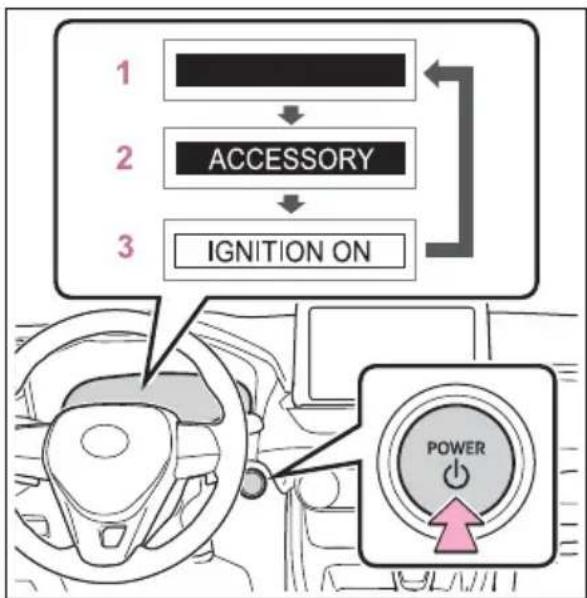
flowchart
graph TD
    A["1"] --> B["2"]
    B --> C["3"]
    C --> D["IGNITION ON"]
    D --> E["POWER"]
1 OFF \*
The emergency flashers can be used.
2 ACC
Some electrical components such as the audio system can be used. "ACCESSORY" will be displayed on the multi-information display.
3 ON
All electrical components can be used.
"IGNITION ON" will be displayed on the multi-information display.
*: If the shift lever is in a position other than P when turning off the hybrid system, the power switch will be turned to ACC, not to OFF.
■Auto power off function
If the vehicle is left in ACC for more than 20 minutes or ON (the hybrid system is not operating) for more than an hour with the shift lever in P, the power switch will automatically turn to OFF. However, this function cannot entirely prevent the 12-volt battery discharge. Do not leave the vehicle with the power switch in ACC or ON for long periods of time when the hybrid system is not operating.

NOTICE
■To prevent 12-volt battery discharge
- Do not leave the power switch in ACC or ON for long periods of time without the hybrid system on.
- If "ACCESSORY" or "IGNITION ON" is displayed on the multi-information display, the power switch is not in OFF. Exit the vehicle after turning the power switch to OFF.
When stopping the hybrid system with the shift lever in a position other than P
If the hybrid system is stopped with the shift lever in a position other than P, the power switch will not be turned to OFF but instead be turned to ACC. Perform the following procedure to turn the switch to OFF:
1 Check that the parking brake is set.
2 Shift the shift lever to P.
3 Check that "ACCESSORY" is displayed on the multi-information display and press the power switch shortly and firmly.
4 Check that "ACCESSORY" or "IGNITION ON" on the multi-information display is off. Turns EV drive mode on/off

NOTICE
■To prevent 12-volt battery discharge
Do not stop the hybrid system when the shift lever is in a position other than P. If the hybrid system is stopped in another shift lever position, the power switch will not be turned to OFF but instead be turned to ACC. If the vehicle is left in ACC, 12-volt battery discharge may occur.
EV drive mode
In EV drive mode, electric power is supplied by the hybrid battery (traction battery), and only the electric motor (traction motor) is used to drive the vehicle.
This mode allows you to drive in residential areas early in the morning and late at night, or in indoor parking lots etc. without concern for noises and gas emissions.
However, when the vehicle proximity notification system is active, the vehicle may produce sound.
Operating instructions
When EV drive mode is turned on, the EV drive mode indicator will come on. Pressing the switch when in EV drive mode will return the vehicle to normal driving (using the gasoline engine and electric motor [traction motor]).
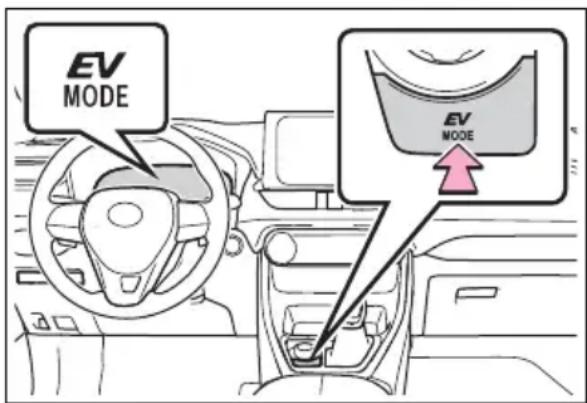
text_image
EV MODE EV MODE■ Situations in which EV drive mode cannot be turned on
It may not be possible to turn EV drive mode on in the following situations. If it cannot be turned on, a buzzer will sound and a message will be shown on the multi-information display.
●The temperature of the hybrid system is high.
The vehicle has been left in the sun, driven on a hill, driven at high speeds, etc.
●The temperature of the hybrid system is low.
The vehicle has been left in temperatures lower than about 32^ F ( 0^ C) for a long period of time etc.
●The gasoline engine is warming up.
●The hybrid battery (traction battery) is low.
The remaining battery level indicated in the Energy monitor display is low. ( P.113)
● Vehicle speed is high.
●The accelerator pedal is depressed firmly or the vehicle is on a hill etc.
●The windshield defogger is in use.
Use the EV drive mode when it becomes available.
■ Switching to EV drive mode when the gasoline engine is cold
If the hybrid system is started while the gasoline engine is cold, the gasoline engine will start automatically after a short period of time in order to warm up.
In this case, you will become unable to switch to EV drive mode. After the hybrid system has started and the "READY" indicator has illuminated, press the EV drive mode switch before the gasoline engine starts to switch to EV drive mode.
■Automatic cancelation of EV drive mode
When driving in EV drive mode, the gasoline engine may automatically restart in the following situations. When EV drive mode is canceled, a buzzer will sound, the EV drive mode indicator will flash and go off and a message will be shown on the multi-information display.
●The hybrid battery (traction battery) becomes low.
The remaining battery level indicated in the Energy monitor display is low. ( P.113)
●Vehicle speed is high.
●The accelerator pedal is depressed firmly or the vehicle is on a hill etc.
Drive the vehicle for a while before attempting to turn on the EV drive mode again.
■Possible driving distance when driving in EV drive mode
EV drive mode's possible driving distance ranges from a few hundred meters to approximately 0.6 mile (1 km). However, depending on vehicle conditions, there are situations when EV drive mode cannot be used.
(The distance that is possible depends on the hybrid battery [traction battery] level and driving conditions.)
Fuel economy
The hybrid system is designed to achieve the best possible fuel economy during normal driving (using the gasoline engine and electric motor [traction motor]). Driving in EV drive mode more than necessary may lower fuel economy.

WARNING
■Caution while driving
When driving in EV drive mode, pay special attention to the area around the vehicle. Because there is no engine noise, pedestrians, people riding bicycles or other people and vehicles in the area may not be aware of the vehicle starting off or approaching them, so take extra care while driving.
Hybrid transmission
Select the shift position depending on your purpose and situation.
Shift position purpose and functions
| Shift position | Objective or function |
| P | Parking the vehicle/starting the hybrid system |
| R Reversing | |
| N Neutral | |
| D | Normal driving*1 |
| S | S mode driving*2 |
*1: To improve fuel efficiency and reduce noise, shift the shift lever to D for normal driving.
*2: By selecting shift ranges using S mode, you can control accelerating force and engine braking force.
■When driving with dynamic radar cruise control with full-speed range activated
Even when performing the following actions with the intent of enabling engine braking, engine braking will not activate because dynamic radar cruise control with full-speed range will not be canceled.
●While driving in S mode, down-shifting to 5 or 4. (→P.221)
- When switching the driving mode to sport mode while driving in D position. (→P.366)
■Restraining sudden start (Drive-Start Control)
→P.190

WARNING
■When driving on slippery road surfaces
Be careful of downshifting and sudden acceleration, as this could result in the vehicle skidding to the side or spinning.

NOTICE
■ Hybrid battery (traction battery) charge
If the shift lever is in N, the hybrid battery (traction battery) will not be charging, even when the engine is running. Therefore, if the vehicle is left with the shift lever in N for a long period of time, the hybrid battery (traction battery) will discharge, and this may result in the vehicle not being able to start.
Shifting the shift lever
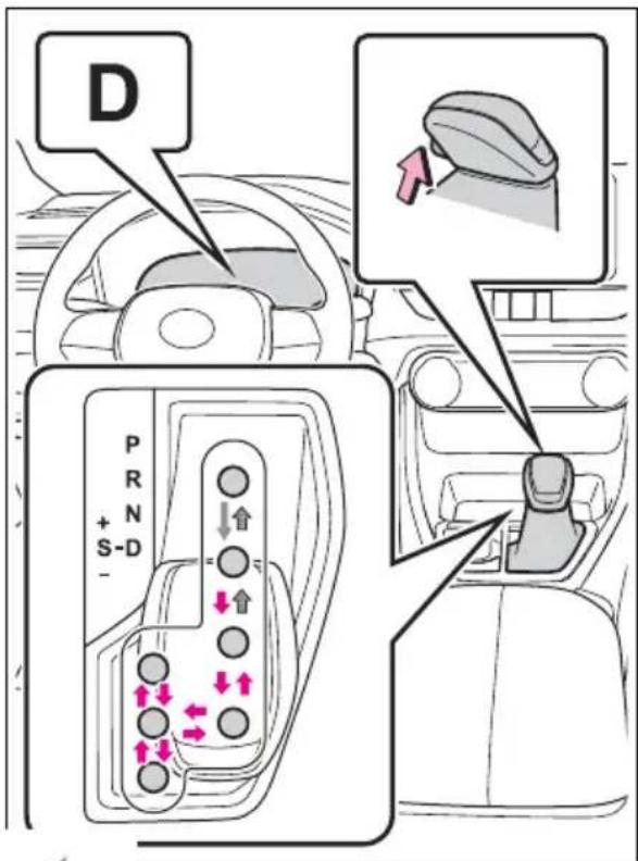
text_image
D P R N + S-D - ↓ ↑ ← ← ← ←
While the power switch is in ON and the brake pedal depressed ^* , shift the shift lever while pushing the shift release button on the shift knob.
Shift the shift lever while
pushing the shift release button on the shift knob.

Shift the shift lever nor-
mally.
When shifting the shift lever between P and D, make sure that the vehicle is completely stopped and the brake pedal is depressed.
*: For the vehicle to be able to be shifted from P, the brake pedal must be depressed before the shift release button is pushed. If
the shift release button is pushed first, the shift lock will not be released.
Shift lock system
The shift lock system is a system to prevent accidental operation of the shift lever in starting.
The shift lever can be shifted from P only when the power switch is in ON, the brake pedal is depressed and the shift release button is pushed.
If the shift lever cannot be shifted from P
First, check whether the brake pedal is being depressed.
If the shift lever cannot be shifted even though the brake pedal is depressed and the shift release button is pushed, there may be a problem with the shift lock system. Have the vehicle inspected by your Toyota dealer immediately.
The following steps may be used as an emergency measure to ensure that the shift lever can be shifted.
Releasing the shift lock:
1 Pull the parking brake switch to check that the parking brake is set. (→P.224)
2 Turn the power switch to OFF.
3 Depress the brake pedal.
4 Pry the cover up with a flathead screwdriver or equivalent tool. To prevent damage to the cover, cover the tip of the screwdriver with a rag.
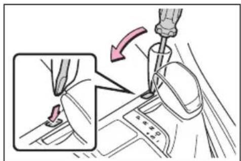
text_image
Diagram showing car gear shift mechanism with labeled parts and directional arrow indicating motion5 Press and hold the shift lock override button and then push the button on the shift knob.
The shift lever can be shifted while both buttons are pressed.
text_image
Diagram illustrating a mechanical device with directional arrows and a magnified inset showing the component's motion.WARNING
■To prevent an accident when releasing the shift lock
Before pressing the shift lock override button, make sure to set the parking brake and depress the brake pedal.
If the accelerator pedal is accidentally depressed instead of the brake pedal when the shift lock override button is pressed and the shift lever is shifted out of P, the vehicle may suddenly start, possibly leading to an accident resulting in death or serious injury.
Selecting the driving mode
→P.366
Changing shift ranges in S mode
When the shift lever is in the S position, the shift lever can be operated as follows:
text_image
s 4 1 21 Upshifting
2 Downshifting
The selected shift range, from S1 to S6, will be displayed on the multi-information display.
The initial shift range in S mode is set automatically to S3, S4 or S5 according to vehicle speed.
S mode
● You can choose from 6 levels of accelerating force and engine braking force.
●A lower shift range will provide greater accelerating force and engine braking force than a higher shift range, and the engine revolutions will also increase.
● To prevent the engine from over-revving, upshifting may automatically occur when the shift range is 4 or lower.
- When the shift range is 4 or lower, holding the shift lever toward “+” sets the shift range to 6.
■Downshifting restriction warning buzzer
To help ensure safety and driving performance, downshifting operation may sometimes be restricted. In some circumstances, downshifting may not be possible even when the shift lever is operated. (A buzzer will sound twice.)
If the “S” indicator does not come on or the “D” indicator is displayed even after shifting the shift lever to S
This may indicate a malfunction in the transmission system. Have the vehicle inspected by your Toyota dealer immediately. (In this situation, the transmission will operate in the same manner as when the shift lever is in D.)
Turn signal lever
Operating instructions
text_image
Diagram illustrating car steering and steering wheel control, showing directional arrows and labeled parts with icons.1 Right turn
2 Lane change to the right (move the lever partway and release it)
The right hand signals will flash 3 times.
3 Lane change to the left (move the lever partway and release it)
The left hand signals will flash 3 times.
4 Left turn
■Turn signals can be operated when
The power switch is in ON.
■If the indicator flashes faster than usual
Check that a light bulb in the front or rear turn signal lights has not
burned out.
If the turn signals stop flashing before a lane change has been performed
Operate the lever again.
■To discontinue flashing of the turn signals during a lane change
Operate the lever in the opposite direction.
Parking brake
The parking brake can be set or released automatically or manually. In automatic mode, the parking brake can be set or released automatically according to shift lever operation. Also, even in automatic mode, the parking brake can be set or released manually.
Operating instructions
■Using the manual mode
The parking brake can be set and released manually.
text_image
PARK (P) A B 1 2 CA Parking brake indicator light (U.S.A.)
B Parking brake indicator light (Canada)
C Parking brake switch indicator
1 Pull the switch to set the
parking brake.
The parking brake indicator light and Parking brake switch indicator will turn on.
Pull and hold the parking brake switch if an emergency occurs and it is necessary to operate the parking brake while driving.
2 Push the switch to release the parking brake.
- Operate the parking brake switch while depressing the brake pedal.
- Parking brake automatic release function (→P.225)
Make sure that the parking brake indicator light and parking brake switch indicator turn off.
If the parking brake indicator light and parking brake switch indicator flash, operate the switch again. (→P.648)
■Turning the automatic mode on
While the vehicle is stopped, pull and hold the parking brake switch until a buzzer sounds and a message is shown on the multi-information display.
text_image
EPB Shift Interlock Function ActivatedWhen the automatic mode is turned on, the parking brake operates as follows.
- When the shift lever is shifted from P, the parking brake will be released, and the parking brake indicator light and parking brake switch indicator will turn off.
- When the shift lever is shifted to P, the parking brake will be set, and the parking brake indicator light and parking brake switch indicator will turn on.
Operate the shift lever with the vehicle stopped and the brake pedal depressed.
■Turning the automatic mode off
While the vehicle is stopped and depressing the brake pedal, press and hold the parking brake switch until a buzzer sounds and a message is shown on the multi-information display.
text_image
EPB Shift Interlock Function Deactivated■Parking brake operation
- When the power switch is not in ON, the parking brake cannot be released using the parking brake switch.
- When the power switch is not in
ON, automatic mode (automatic brake setting and releasing) is not available.
■Parking brake automatic release function
The parking brake will be released automatically when the accelerator pedal is slowly depressed under the following conditions:
The driver's door is closed
●The driver is wearing the seat belt
●The shift lever is in a forward or reverse position.
●The malfunction indicator lamp or brake system warning light is not illuminated
If the automatic release function does not operate, release the parking brake manually.
If "Parking Brake Temporarily Unavailable" is displayed on the multi-information display
If the parking brake is operated repeatedly over a short period of time, the system may restrict operation to prevent overheating. If this happens, refrain from operating the parking brake. Normal operation will return after about 1 minute.
If "Parking Brake Unavailable" is displayed on the multi-information display
Operate the parking brake switch. If the message does not disappear after operating the switch several times, the system may be malfunctioning. Have the vehicle inspected by your Toyota dealer.
■Parking brake operation sound
When the parking brake operates, a motor sound (whirring sound) may be heard. This does not indicate a malfunction.
■Parking brake indicator light
●Depending on the power switch position/mode, the parking brake indicator light will turn on and stay
on as described below:
ON: Comes on until the parking brake is released.
Not in ON: Stays on for approximately 15 seconds.
- When the power switch is turned off with the parking brake set, the parking brake indicator light will stay on for about 15 seconds. This does not indicate a malfunction.
■When the parking brake switch malfunctions
Automatic mode (automatic brake setting and releasing) will be turned on automatically.
Parking the vehicle
→P.189
■Parking brake engaged warning buzzer
A buzzer will sound if the vehicle is driven with the parking brake engaged. "Parking Brake ON" is displayed on the multi-information display (with the vehicle reaching a speed of 5 km/h [3 mph]).
■If the brake system warning light comes on
→P.642
■Usage in winter time
→P.379

WARNING
■When parking the vehicle
Do not leave a child in the vehicle alone. The parking brake may be released unintentionally by a child and there is the danger of the vehicle moving that may lead to an accident resulting in death or serious injury.
■Parking brake switch
Do not set any objects near the parking brake switch. Objects may interfere with the switch and may lead the parking brake to unexpectedly operate.

NOTICE
■When parking the vehicle
Before you leave the vehicle, shift the shift lever to P, set the parking brake and make sure that the vehicle does not move.
■When the system malfunctions
Stop the vehicle in a safe place and check the warning messages.
■When the parking brake cannot be released due to a malfunction
Driving the vehicle with the parking brake set will lead to brake components overheating, which may affect braking performance and increase brake wear. Have the vehicle inspected by your Toyota dealer immediately if this occurs.
Brake Hold
The brake hold system keeps the brake applied when the shift lever is in D, S or N with the system on and the brake pedal has been depressed to stop the vehicle. The system releases the brake when the accelerator pedal is depressed with the shift lever in D or S to allow smooth start off.
Enabling the system
Press the brake hold switch to turn the brake hold system on
The brake hold standby indicator (green) A comes on. While the system is holding the brake, the brake hold operated indicator (yellow) B comes on.
text_image
HOLD A B HOLD■Brake hold system operating conditions
The brake hold system cannot be turned on in the following conditions:
- The driver's door is not closed.
●The driver is not wearing the seat belt.
If any of the conditions above are detected when the brake hold system is enabled, the system will turn off and the brake hold standby indicator light will go off. In addition, if any of the conditions are detected while the system is holding the brake, a warning buzzer will sound and a message will be shown on the multi-information display. The parking brake will then be set automatically.
■Brake hold function
- If the brake pedal is left released for a period of about 3 minutes after the system has started holding the brake, the parking brake will be set automatically. In this case, a warning buzzer sounds and a message is shown on the multi-information display.
● To turn the system off while the system is holding the brake, firmly depress the brake pedal and press the button again.
●The brake hold function may not hold the vehicle when the vehicle is on a steep incline. In this situation, it may be necessary for the driver to apply the brakes. A warning buzzer will sound and the multi-information display will inform the driver of this situation. If a warning message is shown on the multi-information display, read the message and follow the instructions.
■When the parking brake is set automatically while the system is holding the brakes
Perform any of the following operations to release the parking brake:
●Depress the accelerator pedal. (The parking brake will not be released automatically if the seat belt is not fastened.)
- Operate the parking brake switch with the brake pedal depressed.
Make sure that the parking brake indicator light goes off. ( P.224)
■When an inspection at your Toyota dealer is necessary
When the brake hold standby indicator (green) does not illuminate even when the brake hold switch is pressed with the brake hold system operating conditions met, the system may be malfunctioning. Have the vehicle inspected at your Toyota dealer.
If “Brake Hold Malfunction Press Brake to Deactivate Visit Your Dealer” or “Brake Hold Malfunction Visit Your Dealer” is displayed on the multi-information display
The system may be malfunctioning. Have the vehicle inspected by your Toyota dealer.
■Warning messages and buzzers
Warning messages and buzzers are used to indicate a system malfunction or to inform the driver of the need for caution. If a warning message is shown on the multi-information display, read the message and follow the instructions.
■If the brake hold operated indicator flashes
→P.648

WARNING
■When the vehicle is on a steep incline
When using the brake hold system on a steep incline, exercise caution. The brake hold function may not hold the vehicle in such a situation.
■When stopped on a slippery road
The system cannot stop the vehicle when the gripping ability of the tires has been exceeded. Do not use the system when stopped on a slippery road.

NOTICE
■When parking the vehicle
The brake hold system is not designed for use when parking the vehicle for a long period of time. Turning the power switch to OFF while the system is holding the brake may release the brake, which would cause the vehicle to move. When operating the power switch, depress the brake pedal, shift the shift lever to P and set the parking brake.
Headlight switch
The headlights can be operated manually or automatically.
Turning on the headlights
Operating the switch turns on the lights as follows:
U.S.A. (Type A)
text_image
Diagram illustrating car steering wheel and dashboard adjustment, with numbered instructions for adjusting the wheel's position.1 The side marker, parking, tail, license plate, instrument panel lights, and daytime running lights (→P.230) turn on.
2 The headlights and all lights listed above (except daytime running lights) turn on.
3 The headlights, daytime running lights ( P.230) and all the lights listed above turn on and off automatically.
4
U.S.A. (Type B)
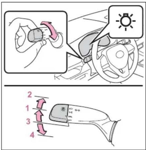
text_image
Diagram illustrating car steering wheel and steering wheel assembly with numbered instructions for turning and adjustment.1 The side marker, parking, tail, license plate, instrument panel lights, and daytime running lights (→P.230) turn on.
2 The headlights and all lights listed above (except daytime running lights) turn on.
3 The daytime running lights turn on. (→P.230)
4 Off
▶ Canada
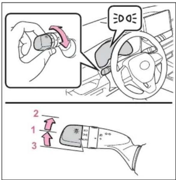
text_image
Diagram illustrating car steering wheel and steering wheel assembly with numbered instructions for adjustment or repair.1 The side marker, parking, tail, license plate, instrument panel lights, and daytime running lights (→P.230) turn on.
2 The headlights and all lights listed above (except daytime running lights) turn on.
3 The headlights, daytime running lights ( P.230) and all the lights listed above turn on and off automatically.
■ AUTO mode can be used when
The power switch is in ON.
■Daytime running light system
● Vehicles without projector headlights: The daytime running lights illuminate using the same lights as the low beam headlight lights, and illuminate dimmer than the low beam headlight lights.
● Vehicles with projector headlights: The daytime running lights illuminate using the same lights as the parking lights and illuminate
brighter than the parking lights.
To make your vehicle more visible to other drivers during daytime driving, the daytime running lights turn on automatically when all of the following conditions are met. (The daytime running lights are not designed for use at night.) The hybrid system is operating The parking brake is released For the U.S.A.: The headlight switch is in the DRLor ^2 DOL AUTO* position
- For Canada: The headlight switch is in the ≥slant 0.01 ≤slant AUTO* position
*: When the surroundings are bright
The daytime running lights remain on after they illuminate, even if the parking brake is set again.
- For the U.S.A.: Daytime running lights can be turned off by operating the switch.
- Compared to turning on the headlights, the daytime running light system offers greater durability and consumes less electricity, so it can help improve fuel economy.
■Headlight control sensor (if equipped)
The sensor may not function properly if an object is placed on the sensor, or anything that blocks the sensor is affixed to the windshield. Doing so interferes with the sensor detecting the level of ambient light and may cause the automatic headlight system to malfunction.
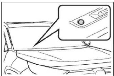
natural_image
Line drawing of a car interior with a magnified inset showing a camera lens (no text or symbols)■Automatic light off system
●When the headlights are on: The
lights turn off 30 seconds after the power switch is turned to ACC or OFF and a door is opened and closed. (The lights turn off immediately if on the key is pressed after all the doors are closed.)
- When only the tail lights are on: The tail lights turn off automatically if the power switch is turned to ACC or OFF and the driver's door is opened.
To turn the lights on again, turn the power switch to ON, or turn the light switch off once and then back to
or position.
Light reminder buzzer
▶ Vehicles without smart key system A buzzer sounds when the power switch is turned to ACC or OFF, the key is removed and the driver's door is opened while the lights are turned on.
▶ Vehicles with smart key system A buzzer sounds when the power switch is turned to ACC or OFF and the driver's door is opened while the lights are turned on.
■Automatic headlight leveling system (if equipped)
The level of the headlights is automatically adjusted according to the number of passengers and the loading condition of the vehicle to ensure that the headlights do not interfere with other road users.
■Windshield wiper linked head-light illumination (if equipped)
When driving during daytime with the headlight switch turned to AUTIF the windshield wipers are used, the headlights will turn on automatically after several seconds to help enhance the visibility of your vehi-
cle.
■12-volt battery-saving function
In order to prevent the 12-volt battery of the vehicle from discharging, if the headlights and/or tail lights are on when the power switch is turned to OFF, the battery saving function will operate and automatically turn off all the lights after approximately 20 minutes.
When any of the following are performed, the battery-saving function is canceled once and then reactivated. All the lights will turn off automatically 20 minutes after the battery-saving function has been reactivated:
- When the headlight switch is operated
●When a door is opened or closed
If "Headlight System Malfunction Visit Your Dealer" is displayed on the multi-information display
The system may be malfunctioning. Have the vehicle inspected by your Toyota dealer.
Customization
Settings (e.g. light sensor sensitivity) can be changed.
Do not leave the lights on longer than necessary when the hybrid system is not running.
Turning on the high beam headlights
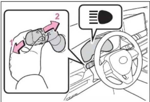
text_image
Diagram showing car steering wheel and dashboard with numbered instructions for joint movement or navigation1 With the headlights on, push the lever away from you to turn on the high beams.
Pull the lever toward you to the center position to turn the high beams off.
2 Pull the lever toward you and release it to flash the high beams once.
You can flash the high beams with the headlights on or off.
AFS (Adaptive Front-lighting System) (if equipped)
AFS (Adaptive Front-lighting System) secures excellent visibility at intersections and on curves by automatically adjusting the direction of the light axis of the headlights according to vehicle speed and the degree of the tire's angle as controlled by steering input.
AFS operates at speeds of approximately 6 mph (10 km/h) or higher.
AHB (Automatic High Beam)
The Automatic High Beam uses an in-vehicle front camera to assess the brightness of streetlights, the lights of vehicles ahead etc., and automatically turns the high beam on or off as necessary.

WARNING
■Limitations of the Automatic High Beam
Do not overly rely on the Automatic High Beam. Always drive safely, taking care to observe your surroundings and turning the high beam on or off manually if necessary.
■To prevent incorrect operation of the Automatic High Beam system
Do not overload the vehicle.
Activating the Automatic High Beam system
1 Press the Automatic High Beam switch.

text_image
Diagram showing a car dashboard with steering wheel and a document labeled 'A' with an upward arrow, indicating a directional or process step.2 Push the lever away from you with the headlight switch in the AUOP position.
The Automatic High Beam indicator will come on when the system is operating.
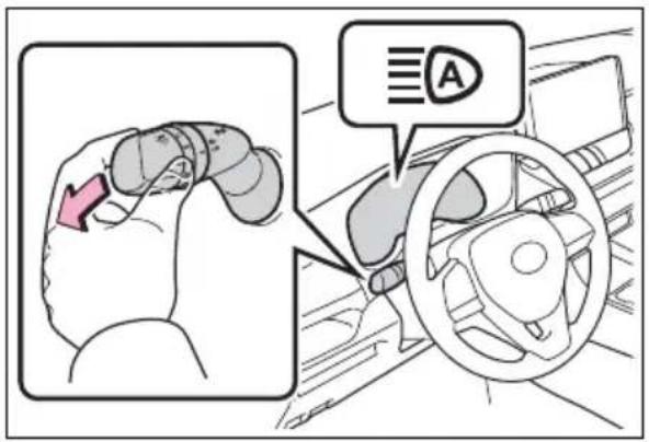
text_image
Diagram showing car steering wheel with a red arrow indicating left side and a speech bubble labeled 'A' pointing to the steering wheel.■High beam automatic turning on or off conditions
- When all of the following conditions are fulfilled, the high beam will be automatically turned on (after approximately 1 second):
- Vehicle speed is above approximately 21 mph (34 km/h) or more.
• The area ahead of the vehicle is dark.
• There are no vehicles ahead with headlights or tail lights turned on.
• There are few streetlights on the road ahead. - If any of the following conditions are fulfilled, the high beam will be automatically turned off:
• Vehicle speed drops below approximately 17 mph (27 km/h). - The area ahead of the vehicle is not dark.
• Vehicles ahead have headlights or tail lights turned on.
• There are many streetlights on the road ahead.
■Front camera detection information
●The high beam may not be automatically turned off in the following situations:
- When oncoming vehicles suddenly appear from a curve
- When the vehicle is cut in front of by another vehicle
- When vehicles ahead are hidden from sight due to repeated curves, road dividers or roadside trees
- When vehicles ahead appear from the faraway lane on a wide road
- When vehicles ahead have no lights
●The high beam may be turned off if a vehicle ahead that is using fog lights without using the headlights is detected.
●House lights, street lights, traffic signals, and illuminated billboards or signs may cause the high beam to switch to the low beams, or the low beams to remain on.
●The following factors may affect the amount of time taken to turn the high beam on or off:
- The brightness of headlights, fog lights, and tail lights of vehicles ahead
• The movement and direction of vehicles ahead
- When a vehicle ahead only has operational lights on one side
- When a vehicle ahead is a two-wheeled vehicle
- The condition of the road (gradient, curve, condition of the road surface etc.)
• The number of passengers and amount of luggage
●The high beam may be turned on or off when the driver does not expect it.
●Bicycles or similar objects may not be detected.
In the situations shown below, the system may not be able to accurately detect surrounding brightness levels. This may cause the low beams to remain on or the high beams to cause problems for pedestrians, vehicles ahead or other parties. In these cases, manually switch between the high and low beams.
- In bad weather (rain, snow, fog, sandstorms, etc.)
- The windshield is obscured by fog, mist, ice, dirt, etc.
- The windshield is cracked or damaged
- The front camera is deformed or dirty
- When the temperature of the front camera is extremely high
- Surrounding brightness levels are equal to those of headlights, tail lights or fog lights
- When headlights or tail lights of vehicles ahead are turned off, dirty, changing color, or not aimed properly
- When the vehicle is hit by water, snow, dust, etc. from a preceding vehicle
- When driving through an area of intermittently changing brightness and darkness
- When frequently and repeatedly driving ascending/descending roads, or roads with rough, bumpy or uneven surfaces (such as stone-paved roads, gravel roads, etc.)
- When frequently and repeatedly taking curves or driving on a winding road
- There is a highly reflective object ahead of the vehicle, such as a sign or mirror
- The back of a vehicle ahead is highly reflective, such as a container on a truck
- The vehicle's headlights are damaged or dirty, or are not aimed properly
- The vehicle is listing or titling due to a flat tire, a trailer being towed, etc.
- The high beam and low beam are repeatedly being switched between in an abnormal manner
- The driver believes that the high beam may be causing problems or distress to other drivers or pedestrians nearby
If "Headlight System Malfunction Visit Your Dealer" is displayed on the multi-information display
The system may be malfunctioning. Have the vehicle inspected by your Toyota dealer.
■ Temporarily lowering sensor sensitivity
The sensitivity of the sensor can be temporarily lowered.
1 Turn the power switch to OFF while the following conditions are met.
●The headlight switch is in

AUTO position.
●The headlight switch lever is in high beam position.
●Automatic High Beam switch is on.
2 Turn the power switch to ON.
3 Within 60 seconds after step 2, repeat pulling the headlight switch lever to the original position then pushing it to the high beam position quickly 10 times, then leave the lever in high beam position.
4 If the sensitivity is changed, the Automatic High Beam indicator is turn on and off 3 times.
Automatic High Beam (headlights) may turn on even when the vehicle is stopped.
Turning the high beam on/off manually
■Switching to the low beam
Pull the lever to original position.
The Automatic High Beam indicator will turn off.
Push the lever away from you to activate the Automatic High Beam system again.
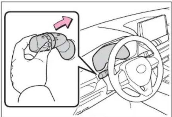
text_image
Diagram showing a hand holding a car's steering wheel, with an inset highlighting the left side of the wheel.■Switching to the high beam
Press the Automatic High Beam switch.
The Automatic High Beam indicator will turn off and the high beam indicator will turn on.
Press the switch to activate the Automatic High Beam system again.
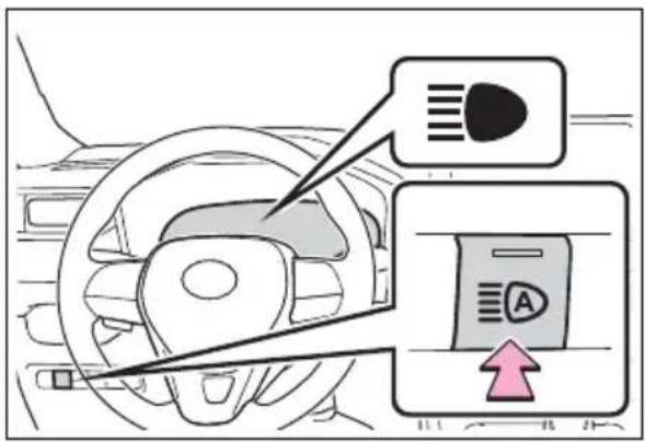
text_image
Diagram showing car steering wheel and driver's seat with labeled icons and directional arrowFog light switch\*
*: If equipped
The fog lights offer improved visibility in difficult driving conditions, such as in rain and fog.
Operating procedure
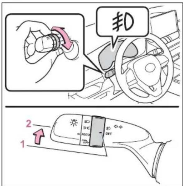
text_image
#0 2 11 OFF ^1 or O ^2 Turns the fog lights off
2 Turns the fog lights on
*1: For the U.S.A.
*2:For Canada
■Fog lights can be used when
The headlights are on in low beam.
Windshield wipers and washer
Operating the lever can switch between automatic operation and manual operation, or can use the washer.

NOTICE
■When the windshield is dry Do not use the wipers, as they may damage the windshield.
Operating the wiper lever
Operating the lever operates the wipers or washer as follows:
▶ Intermittent windshield wipers
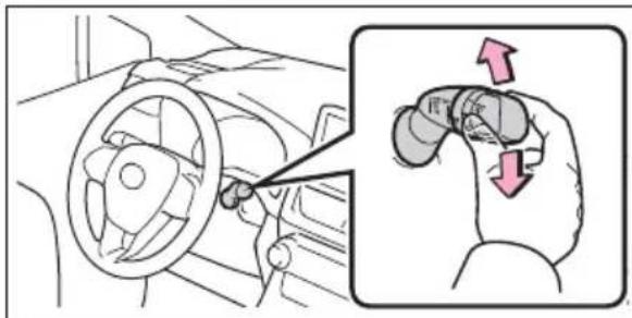
text_image
Diagram showing car steering wheel and hand grip mechanism with directional arrows indicating motion or movement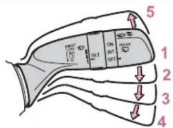
text_image
5 1 2 3 41 OFF *1 or o *2 Off
2 INT *1 or 📋*2 Intermittent operation
3 LO ^1 or ^2 Low speed operation
4 HI ^1 or ^2 High speed operation
5 MIST ^1 or ^2 Temporary operation
*1: For the U.S.A.
*2:For Canada
If equipped, wiper intervals can be adjusted when intermittent operation is selected.
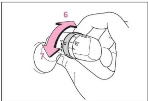
text_image
6 76 Increases the intermittent windshield wiper frequency
7 Decreases the intermittent windshield wiper frequency
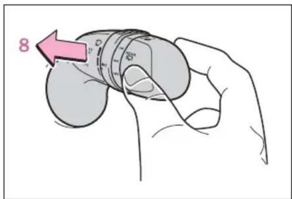
text_image
88 Washer/wiper dual operation
Pulling the lever operates the wipers and washer.
The wipers will automatically operate a couple of times after the washer squirts.
▶ Rain-sensing windshield wipers
text_image
Diagram illustrating car steering wheel and hand grip mechanism with labeled parts and directional arrows1 OFF *1 or o *2 Off
2 Rain-sensing operation
3 LO *1 or ▼ *2 Low speed operation
4 HI ^1 or ^2 High speed operation
5 MIST ^1 or ^2 Temporary operation
*1: For the U.S.A.
*2:For Canada
When "AUTO" is selected, the wipers will operate automatically when the sensor detects falling rain. The system automatically adjusts wiper timing in accordance with rain volume and vehicle speed.
The sensor sensitivity can be adjusted when "AUTO" is selected.
text_image
6 76 Increases the sensitivity
7 Decreases the sensitivity
text_image
88 Washer/wiper dual operation
Pulling the lever operates the wipers and washer.
The wipers will automatically operate a couple of times after the washer squirts.
■The windshield wipers and washer can be operated when
The power switch is in ON.
■Effects of vehicle speed on wiper operation
▶ Vehicles with intermittent wind-shield wipers
With low speed windshield wiper operation selected, wiper operation will be switched from low speed to intermittent wiper operation when the vehicle is stationary. (However, when the wiper intervals are adjusted to highest level, the mode
will not switch.)
▶ Vehicles with rain-sensing wind-shield wipers
With low speed windshield wiper operation selected, wiper operation will be switched from low speed to intermittent wiper operation when the vehicle is stationary. (However, when the sensor sensitivity is adjusted to the highest level, the mode will not switch.)
■ Raindrop sensor (vehicles with rain-sensing windshield wipers)
●The raindrop sensor judges the amount of raindrops.
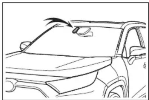
natural_image
Line drawing of a car's front and rear side view showing the roof, window, and side door (no text or symbols)- If the wiper switch is turned to the "AUTO" position while the power switch is in ON, the wipers will operate once to show that "AUTO" mode is activated.
- If the wiper sensitivity is adjusted to higher, the wiper may operate once to indicate the change of sensitivity.
- If the temperature of the raindrop sensor is 185°F (85°C) or higher, or 5°F (-15°C) or lower, the automatic operation may not occur. In this case, operate the wipers in any mode other than “AUTO”.
■If no windshield washer fluid sprays
Check that the washer nozzles are not blocked if there is washer fluid in the windshield washer fluid reservoir.

WARNING
■Caution regarding the use of windshield wipers in "AUTO" mode (vehicles with rain-sensing windshield wipers)
The windshield wipers may operate unexpectedly if the sensor is touched or the windshield is subject to vibration in "AUTO" mode. Take care that your fingers or anything else does not become caught in the windshield wipers.
■Caution regarding the use of washer fluid
When it is cold, do not use the washer fluid until the windshield becomes warm. The fluid may freeze on the windshield and cause low visibility. This may lead to an accident, resulting in death or serious injury.

NOTICE
■When the washer fluid tank is empty
Do not operate the switch continually as the washer fluid pump may overheat.
■When a nozzle becomes blocked
In this case, contact your Toyota dealer.
Do not try to clear it with a pin or other object. The nozzle will be damaged.
■To prevent 12-volt battery discharge
Do not leave the wipers on longer than necessary when the hybrid system is off.
Rear window wiper and washer
The rear window wiper and washer can be used by operating the lever.

NOTICE
■When the rear window is dry
Do not use the wiper, as it may damage the rear window.
Operating the wiper lever
Operating the switch operates the rear wiper as follows:
text_image
Diagram illustrating car steering wheel and rear door control with labeled directional buttons and motion arrows1 OFF *1 or o *2 Off
2 INT ^1 or --- ^2 Intermittent operation
3 ON ^1 or — ^2 Normal operation
*1: For the U.S.A.
*2:For Canada
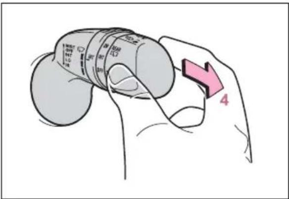
text_image
1 MIST OUT INT LPG IN 200 300 4 5 6 7 8 9 10 11 12 13 14 15 16 17 18 19 20 21 22 23 24 25 26 27 28 29 30 31 32 33 34 35 36 37 38 39 40 41 42 43 44 45 46 47 48 49 50 51 52 53 54 55 56 57 58 59 60 61 62 63 64 65 66 67 68 69 70 71 72 73 74 75 76 77 78 79 80 81 82 83 84 85 86 87 88 89 90 91 92 93 94 95 96 97 98 99 1004 Washer/wiper dual operation
Pushing the lever operates the wiper and washer.
The wiper will automatically operate a couple of times after the washer squirts.
■The rear window wiper and washer can be operated when
The power switch is in ON.
■If no washer fluid sprays
Check that the washer nozzle is not blocked if there is washer fluid in the washer fluid reservoir.
■Back door opening linked rear window wiper stop function
When the rear window wiper is operating, if the back door is opened while the vehicle is stopped, operation of the rear window wiper will be stopped to prevent anyone near the vehicle from being sprayed by water from the wiper. When the back door is closed, wiper operation will resume.*
*: The setting must be customized at your Toyota dealer.
■Reverse-linked rear window wiper function
When the shift lever is shifted to R when the front wipers are operating, the rear window wiper will operate once.
Customization
Setting of the reverse-linked function can be changed. (Customizable features: →P.714)

NOTICE
■When the washer fluid tank is empty
Do not operate the switch continually as the washer fluid pump may overheat.
■When a nozzle becomes blocked
In this case, contact your Toyota dealer.
Do not try to clear it with a pin or other object. The nozzle will be damaged.
■To prevent 12-volt battery discharge
Do not leave the wiper on longer than necessary when the hybrid system is off.
Opening the fuel tank cap
The fuel tank of your vehicle has a special structure, which requires a reduction in fuel tank pressure before refueling. After the opener switch has been pressed, it will take several seconds until the vehicle is ready for refueling.
Before refueling the vehicle
- Close all the doors and windows, and turn the power switch to OFF.
- Confirm the type of fuel.
Fuel types
→P.694
■Fuel tank opening for unleaded gasoline
To help prevent incorrect fueling, your vehicle has a fuel tank opening that only accommodates the special nozzle on unleaded fuel pumps.

WARNING
■When refueling the vehicle
Observe the following precautions while refueling the vehicle. Failure to do so may result in death or serious injury.
● After exiting the vehicle and before opening the fuel door, touch an unpainted metal surface to discharge any static electricity. It is important to discharge static electricity before refueling because sparks resulting from static electricity can cause fuel vapors to ignite while refueling.
●Always hold the grips on the fuel tank cap and turn it slowly to remove it. A whooshing sound may be heard when the fuel tank cap is loosened. Wait until the sound cannot be heard before fully removing the cap. In hot weather, pressurized fuel may spray out of the filler neck and cause injury.
- Do not allow anyone that has not discharged static electricity from their body to come close to an open fuel tank.
- Do not inhale vaporized fuel. Fuel contains substances that are harmful if inhaled.
- Do not smoke while refueling the vehicle. Doing so may cause the fuel to ignite and cause a fire.
- Do not return to the vehicle or touch any person or object that is statically charged. This may cause static electricity to build up, resulting in a possible ignition hazard.

WARNING
When refueling
Observe the following precautions to prevent fuel overflowing from the fuel tank:
- Securely insert the fuel nozzle into the fuel filler neck.
- Stop filling the tank after the fuel nozzle automatically clicks off.
- Do not top off the fuel tank.

NOTICE
Refueling
●Finish refueling within 30 minutes. If more than 30 minutes passes, the internal valve closes. In this condition, fuel may overflow during the refueling process. Press the fuel filler door opener switch again.
- Do not spill fuel during refueling. Doing so may damage the vehicle, such as causing the emission control system to operate abnormally or damaging fuel system components or the vehicle's painted surface.
Opening the fuel tank cap
1 Press the opener to open the fuel filler door.
The fuel filler door will open within about 10 seconds of the switch being pressed. Before refueling is possible, a message will be shown on the multi-information display in the instrument cluster to indicate the progress of the fuel filler door
opener.
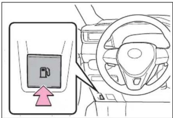
text_image
Diagram showing a car seatbelt with a highlighted device and directional arrow, likely indicating vehicle status or navigation.2 Turn the fuel tank cap slowly to open it and put it into the holder on the fuel filler door.
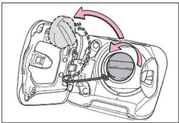
natural_image
Technical diagram of a mechanical assembly with highlighted components and directional arrows (no text or labels)■If the fuel filler door cannot be opened
→P.669
Closing the fuel tank cap
After refueling, turn the fuel tank cap until you hear a click. Once the cap is released, it will turn slightly in the opposite direction.
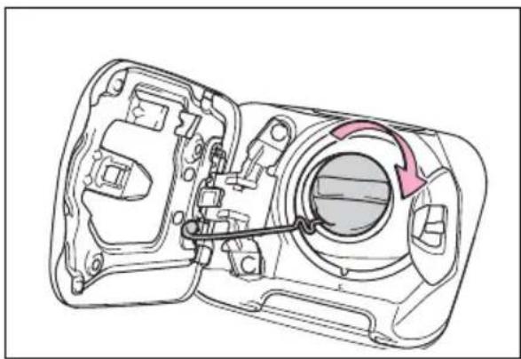
natural_image
Technical line drawing of a mechanical component with internal components and directional arrows (no text or symbols)When "Check Fuel Cap" is displayed on the multi-information display
The fuel tank cap may be unfastened or loose. Turn the power switch to OFF, check the cap and tighten it securely. If the message remains, wait a few seconds and then turn the power switch to OFF once again.

WARNING
■When replacing the fuel tank cap
Do not use anything but a genuine Toyota fuel tank cap designed for your vehicle. Doing so may cause a fire or other incident which may result in death or serious injury.

NOTICE
When refueling
When refueling your vehicle, make sure that the fuel filler door lock is not pushed by the fuel nozzle boot, etc., as this may cause a valve to close, possibly resulting in a fuel spill.
If the fuel filler door lock has been pushed, operate the fuel filler door opener switch in the vehicle before continuing to refuel.
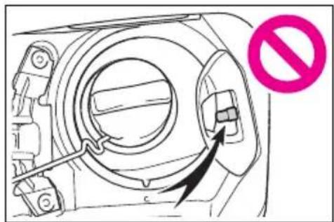
natural_image
Diagram of a mechanical device with a circular component and directional arrow, no text or symbols presentToyota Safety Sense 2.0
The Toyota Safety Sense 2.0 consists of the following drive assist systems and contributes to a safe and comfortable driving experience:
Driving assist system
■PCS (Pre-Collision System)
→P.250
■LTA (Lane Tracing Assist)
→P.258
■AHB (Automatic High Beam)
→P.232
■RSA (Road Sign Assist) (if equipped)
→P.268
■ Dynamic radar cruise control with full-speed range
→P.271

WARNING
Toyota Safety Sense 2.0
The Toyota Safety Sense 2.0 is designed to operate under the assumption that the driver will drive safely, and is designed to help reduce the impact to the occupants and the vehicle in the case of a collision or assist the driver in normal driving conditions.
As there is a limit to the degree of recognition accuracy and control performance that this system can provide, do not overly rely on this system. The driver is always responsible for paying attention to the vehicle's surroundings and driving safely.
Sensors
Two types of sensors, located behind the front grille and wind-shield, detect information necessary to operate the drive assist systems.
text_image
A BA Radar sensor
B Front camera

WARNING
■To avoid malfunction of the radar sensor
Observe the following precautions.
Otherwise, the radar sensor may not operate properly, possibly leading to an accident resulting in death or serious injury.
- Keep the radar sensor and the radar sensor cover clean at all times.
text_image
A BA Radar sensor
B Radar sensor cover
If the front of the radar sensor or the front or back of the radar sensor cover is dirty or covered with water droplets, snow, etc., clean it.
Clean the radar sensor and radar sensor cover with a soft cloth to avoid damaging them.
- Do not attach accessories, stickers (including transparent stickers) or other items to the radar sensor, radar sensor cover or surrounding area.
- Do not subject the radar sensor or its surrounding area to a strong impact. If the radar sensor, front grille, or front bumper has been subjected to a strong impact, have the vehicle inspected by your Toyota dealer.
- Do not disassemble the radar sensor.
- Do not modify or paint the radar sensor or radar sensor cover.
In the following cases, the radar sensor must be recalibrated. Contact your Toyota dealer for details.
- When the radar sensor or front grille are removed and installed, or replaced - When the front bumper is replaced
■To avoid malfunction of the front camera
Observe the following precautions.
Otherwise, the front camera may not operate properly, possibly leading to an accident resulting in death or serious injury.
- Keep the windshield clean at all times.
- If the windshield is dirty or covered with an oily film, water droplets, snow, etc., clean the windshield.
- If a glass coating agent is applied to the windshield, it will still be necessary to use the windshield wipers to remove water droplets, etc. from the area of the windshield in front of the front camera.
- If the inner side of the wind-shield where the front camera is installed is dirty, contact your Toyota dealer.

WARNING
text_image
A B- Do not attach objects, such as stickers, transparent stickers, etc., to the outer side of the windshield in front of the front camera (shaded area in the illustration).
A From the top of the windshield to approximately 0.4 in. (1 cm) below the bottom of the front camera
B Approximately 7.9 in. (20 cm) (Approximately 4.0 in. [10 cm] to the right and left from the center of the front camera) - If the part of the windshield in front of the front camera is fogged up or covered with condensation, or ice, use the windshield defogger to remove the fog, condensation, or ice. (→P.526)
- If water droplets cannot be properly removed from the area of the windshield in front of the front camera by the windshield wipers, replace the wiper insert or wiper blade.
- Do not attach window tint to the windshield.
-
Replace the windshield if it is damaged or cracked. After replacing the windshield, the front camera must be recalibrated. Contact your Toyota dealer for details.
-
Do not allow liquids to contact the front camera.
- Do not allow bright lights to shine into the front camera.
- Do not dirty or damage the front camera.
When cleaning the inside of the windshield, do not allow glass cleaner to contact the lens of the front camera. Also, do not touch the lens.
If the lens is dirty or damaged, contact your Toyota dealer.
● Do not subject the front camera to a strong impact. - Do not change the installation position or direction of the front camera or remove it.
- Do not disassemble the front camera.
- Do not modify any components of the vehicle around the front camera (inside rear view mirror, etc.) or ceiling.
- Do not attach any accessories to the hood, front grille or front bumper that may obstruct the front camera. Contact your Toyota dealer for details.
- If a surfboard or other long object is to be mounted on the roof, make sure that it will not obstruct the front camera.
- Do not modify the headlights or other lights.
Certification
For vehicles sold in the U.S.A., Hawaii, American Samoa, Guam, Saipan and Puerto Rico
FCC ID: HYQDNMWR009
NOTE:
This device complies with part 15 of the FCC Rules. Operation is subject to the following two conditions: (1) This device may not cause harmful interference, and (2) this device must accept any interference received, including interference that may cause undesired operation.
FCC WARNING:
Changes or modifications not expressly approved by the party responsible for compliance could void the user's authority to operate the equipment.
Radiofrequency radiation exposure Information:
This equipment complies with FCC radiation exposure limits set forth for an uncontrolled environment. This equipment should be installed and operated with minimum distance of 20 cm between the radiator (antenna) and your body. This transmitter must not be co-located or operating in conjunction with any other antenna or transmitter.
For vehicles sold in Canada
NOTE:
This device contains licence-exempt transmitter(s)/receiver(s) that comply with Innovation, Science and Economic Development Canada's licence-exempt RSS(s). Operation is subject to the following two conditions:
(1) This device may not cause interference.
(2) This device must accept any interference, including interference that may cause undesired operation of the device.
This equipment complies with ISED radiation exposure limits set forth for an uncontrolled environment and meets RSS-102 of the ISED radio frequency (RF) Exposure rules. This equipment should be installed and operated keeping the radiator at least 20 cm or more away from person's body.
NOTE:
A system may be temporarily unavailable or there may be a malfunction in the system.
- In the following situations, perform the actions specified in the table. When the normal operating conditions are detected, the message will disappear and the system will become operational.
If the message does not disappear, contact your Toyota dealer.
| Situation Actions | |
| When the area around a sensor is covered with dirt, moisture (fogged up, covered with condensation, ice, etc.), or other foreign matter | To clean the part of the windshield in front of the front camera, use the windshield wipers or the windshield defogger of the air conditioning system ( P.526). |
| When the temperature around the front camera is outside of the operational range, such as when the vehicle is in the sun or in an extremely cold environment | If the front camera is hot, such as after the vehicle had been parked in the sun, use the air conditioning system to decrease the temperature around the front camera.If a sunshade was used when the vehicle was parked, depending on its type, the sunlight reflected from the surface of the sunshade may cause the temperature of the front camera to become excessively high. |
| If the front camera is cold, such as after the vehicle is parked in an extremely cold environment, use the air conditioning system to increase the temperature around the front camera. | |
| The area in front of the front camera is obstructed, such as when the hood is open or a sticker is attached to the part of the windshield in front of the front camera. | Close the hood, remove the sticker, etc. to clear the obstruction. |
- In the following situations, if the situation has changed (or the vehicle has been driven for some time) and the normal operating conditions are detected, the message will disappear and the system will become operational.
If the message does not disappear, contact your Toyota dealer.
- When the temperature around the radar sensor is outside of the operational range, such as when the vehicle is in the sun or in an extremely cold environment
- When the front camera cannot detect objects in front of the vehicle, such as when driving in the dark, snow, or fog, or when bright lights are shining into the front camera
PCS (Pre-Collision System)
The pre-collision system uses a radar sensor and front camera to detect objects ( P.250) in front of the vehicle. When the system determines that the possibility of a frontal collision with an object is high, a warning operates to urge the driver to take evasive action and the potential brake pressure is increased to help the driver avoid the collision. If the system determines that the possibility of a frontal collision with an object is extremely high, the brakes are automatically applied to help avoid the collision or help reduce the impact of the collision.
The pre-collision system can be disabled/enabled and the warning timing can be changed. ( P.252)
Detectable objects
The system can detect the following:
- Vehicles
- Bicyclists
- Pedestrians
System functions
■Pre-collision warning
When the system determines that the possibility of a frontal collision is high, a buzzer will sound and a warning message will be displayed on the multi-information display to urge the driver to take evasive action.
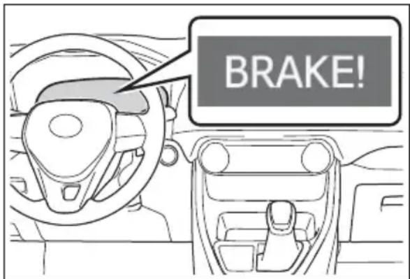
text_image
BRAKE!■Pre-collision brake assist
When the system determines that the possibility of a frontal collision is high, the system applies greater braking force in relation to how strongly the brake pedal is depressed.
■Pre-collision braking
If the system determines that the possibility of a frontal collision is extremely high, the brakes are automatically applied to help avoid the collision or reduce the impact of the collision.

WARNING
■Limitations of the pre-collision system
The driver is solely responsible for safe driving. Always drive safely, taking care to observe your surroundings. Do not use the pre-collision system instead of normal braking operations under any circumstances. This system will not prevent collisions or lessen collision damage or injury in every situation. Do not overly rely on this system. Failure to do so may lead to an accident, resulting in death or serious injury.
Although this system is designed to help avoid a collision or help reduce the impact of the collision, its effectiveness may change according to various conditions, therefore the system may not always be able to achieve the same level of performance. Read the following conditions carefully. Do not overly rely on this system and always drive carefully.
- Conditions under which the system may operate even if there is no possibility of a collision: P.254
- Conditions under which the system may not operate properly: P.255
- Do not attempt to test the operation of the pre-collision system yourself. Depending on the objects used for testing (dummies, cardboard objects imitating detectable objects, etc.), the system may not operate properly, possibly leading to an accident.
■Pre-collision braking
- When the pre-collision braking function is operating, a large amount of braking force will be applied.
- If the vehicle is stopped by the operation of the pre-collision braking function, the pre-collision braking function operation will be canceled after approximately 2 seconds. Depress the brake pedal as necessary.
●The pre-collision braking function may not operate if certain operations are performed by the driver. If the accelerator pedal is being depressed strongly or the steering wheel is being turned, the system may determine that the driver is taking evasive action and possibly prevent the pre-collision braking function from operating.
In some situations, while the pre-collision braking function is operating, operation of the function may be canceled if the accelerator pedal is depressed strongly or the steering wheel is turned and the system determines that the driver is taking evasive action.
- If the brake pedal is being depressed, the system may determine that the driver is taking evasive action and possibly delay the operation timing of the pre-collision braking function.
■When to disable the pre-collision system
In the following situations, disable the system, as it may not operate properly, possibly leading to an accident resulting in death or serious injury:
●When the vehicle is being towed

WARNING
- When your vehicle is towing another vehicle
- When transporting the vehicle via truck, boat, train or similar means of transportation
- When the vehicle is raised on a lift with the hybrid system on and the tires are allowed to rotate freely
- When inspecting the vehicle using a drum tester such as a chassis dynamometer or speedometer tester, or when using an on vehicle wheel balancer
- When a strong impact is applied to the front bumper or front grille, due to an accident or other reasons
- If the vehicle cannot be driven in a stable manner, such as when the vehicle has been in an accident or is malfunctioning
- When the vehicle is driven in a sporty manner or off-road
- When the tires are not properly inflated
- When the tires are very worn
- When tires of a size other than specified are installed
●When tire chains are installed - When a compact spare tire or an emergency tire puncture repair kit is used
- If equipment (snow plow, etc.) that may obstruct the radar sensor or front camera is temporarily installed to the vehicle
Changing settings of the pre-collision system
■Enabling/disabling the pre-collision system
The pre-collision system can be enabled/disabled on the screen (→P.109) of the multi-information display.
The system is automatically enabled each time the power switch is turned to ON.
If the system is disabled, the PCS warning light will turn on and a message will be displayed on the multi-information display.
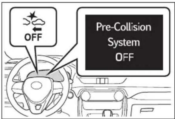
text_image
OFF Pre-Collision System OFF■Changing the pre-collision warning timing
The pre-collision warning timing can be changed on the screen (→P.109) of the multi-information display.
The warning timing setting is retained when the power switch is turned to OFF. However, if the pre-collision system is disabled and re-enabled, the operation timing will return to the default setting (middle).
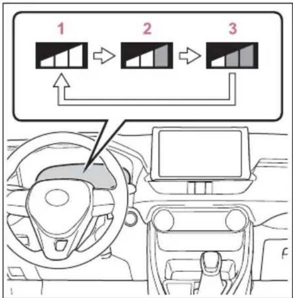
flowchart
graph TD
    A["1: Car Top"] --> B["2: Car Bottom"]
    B --> C["3: Assembly Window"]
    style A fill:#f9f,stroke:#333
    style B fill:#ccf,stroke:#333
    style C fill:#cfc,stroke:#333
1 Early
2 Middle
This is the default setting.
3 Late
■Operational conditions
The pre-collision system is enabled and the system determines that the possibility of a frontal collision with a detected object is high. Each function is operational at the following speed
●Pre-collision warning
| Detectable objects Vehicle speed | Relative speed between your vehicle and object | |
| Vehicles | Approx. 7 to 110 mph (10 to 180 km/h) | Approx. 7 to 110 mph (10 to 180 km/h) |
| Bicyclists and pedestrians | Approx. 7 to 50 mph (10 to 80 km/h) | Approx. 7 to 50 mph (10 to 80 km/h) |
●Pre-collision brake assist
| Detectable objects Vehicle speed | Relative speed between your vehicle and object | |
| Vehicles | Approx. 20 to 110 mph (30 to 180 km/h) | Approx. 20 to 110 mph (30 to 180 km/h) |
| Bicyclists and pedestrians | Approx. 20 to 50 mph (30 to 80 km/h) | Approx. 20 to 50 mph (30 to 80 km/h) |
●Pre-collision braking
| Detectable objects Vehicle speed | Relative speed between your vehicle and object | |
| Vehicles | Approx. 7 to 110 mph (10 to 180 km/h) | Approx. 7 to 110 mph (10 to 180 km/h) |
| Bicyclists and pedestrians | Approx. 7 to 50 mph (10 to 80 km/h) | Approx. 7 to 50 mph (10 to 80 km/h) |
The system may not operate in the following situations:
- If a 12-volt battery terminal has been disconnected and reconnected and then the vehicle has not been driven for a certain amount of time
- If the shift lever is in R
- When the VSC OFF indicator is illuminated (only the pre-collision warning function will be operational)
■Object detection function
The system detects objects based on their size, profile, motion, etc. However, an object may not be detected depending on the surrounding brightness and the motion, posture, and angle of the detected object, preventing the system from operating properly. (→P.255) The illustration shows an image of detectable objects.
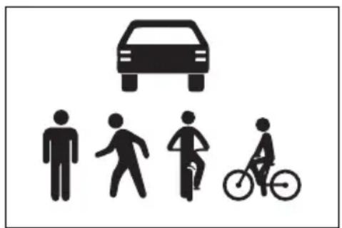
natural_image
Silhouette icons of a car, human figures, and a bicycle (no text or symbols)■Cancelation of the pre-collision braking
If either of the following occur while the pre-collision braking function is operating, it will be canceled:
●The accelerator pedal is depressed strongly.
●The steering wheel is turned sharply or abruptly.
■Conditions under which the system may operate even if there is no possibility of a collision
- In some situations such as the following, the system may determine that there is a possibility of a frontal collision and operate.
- When passing a detectable object, etc.
- When changing lanes while overtaking a detectable object, etc.
- When approaching a detectable object in an adjacent lane or on the roadside, such as when changing the course of travel or driving on a winding road
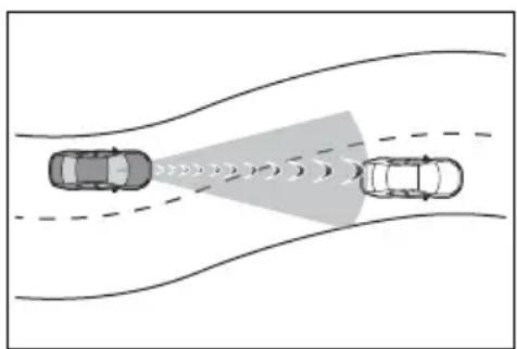
natural_image
Diagram showing two cars on curved road with traffic light propagation (no text or symbols)- When rapidly closing on a detectable object, etc.
- When approaching objects on the roadside, such as detectable objects, guardrails, utility poles, trees, or walls
- When there is a detectable object or other object by the roadside at
the entrance of a curve
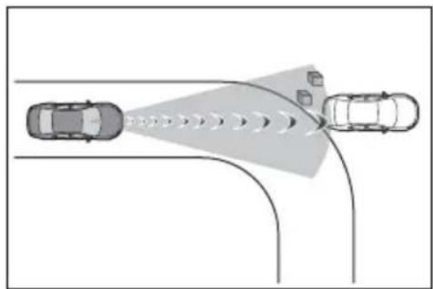
text_image
Diagram showing vehicle detection with a shaded area and directional arrows indicating signal flow or navigation- When there are patterns or paint in front of your vehicle that may be mistaken for a detectable object
- When the front of your vehicle is hit by water, snow, dust, etc.
- When overtaking a detectable object that is changing lanes or making a right/left turn
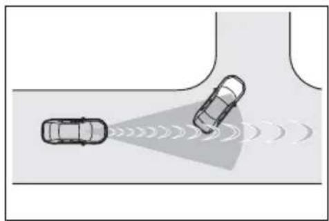
natural_image
Diagram showing two cars on a road with sound waves indicating traffic or sensor detection (no text or symbols)- When passing a detectable object in an oncoming lane that is stopped to make a right/left turn
natural_image
Top-down diagram of two cars on a road with sound waves, no text or symbols present- When a detectable object approaches very close and then stops before entering the path of your vehicle
- If the front of your vehicle is raised or lowered, such as when on an uneven or undulating road surface
- When driving on a road surrounded by a structure, such as in a tunnel or on an iron bridge
- When there is a metal object (manhole cover, steel plate, etc.), steps, or a protrusion in front of
your vehicle
- When passing under an object (road sign, billboard, etc.)
natural_image
Diagram of a car driving on a road with sensor waves projecting onto a lane (no text or symbols)- When approaching an electric toll gate barrier, parking area barrier, or other barrier that opens and closes
- When using an automatic car wash
- When driving through or under objects that may contact your vehicle, such as thick grass, tree branches, or a banner
natural_image
Illustration of a car driving on a road with trees and a vehicle in motion (no text or symbols)- When driving through steam or smoke
- When driving near an object that reflects radio waves, such as a large truck or guardrail
- When driving near a TV tower, broadcasting station, electric power plant, or other location where strong radio waves or electrical noise may be present
■ Situations in which the system may not operate properly
In some situations such as the following, an object may not be detected by the radar sensor and front camera, preventing the system from operating properly:
- When a detectable object is approaching your vehicle
- When your vehicle or a detectable object is wobbling
- If a detectable object makes an abrupt maneuver (such as sudden swerving, acceleration or deceleration)
- When your vehicle approaches a detectable object rapidly
- When a detectable object is not directly in front of your vehicle
natural_image
Diagram showing two cars approaching a target vehicle with motion arrows, no text or symbols present- When a detectable object is near a wall, fence, guardrail, manhole cover, vehicle, steel plate on the road, etc.
- When a detectable object is under a structure
- When part of a detectable object is hidden by an object, such as large baggage, an umbrella, or guardrail
- When multiple detectable objects are close together
- If the sun or other light is shining directly on a detectable object
- When a detectable object is a shade of white and looks extremely bright
- When a detectable object appears to be nearly the same color or brightness as its surroundings
- If a detectable object cuts or suddenly emerges in front of your vehicle
- When the front of your vehicle is hit by water, snow, dust, etc.
- When a very bright light ahead, such as the sun or the headlights of oncoming traffic, shines directly into the front camera
- When approaching the side or front of a vehicle ahead
• If a vehicle ahead is a motorcycle - If a vehicle ahead is narrow, such as a personal mobility vehicle
- If a preceding vehicle has a small rear end, such as an unloaded
truck
- If a preceding vehicle has a low rear end, such as a low bed trailer
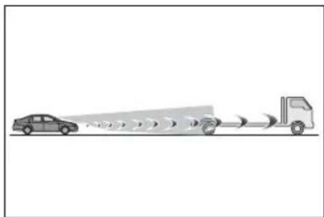
natural_image
Diagram showing a car approaching a truck with motion blur effect (no text or symbols)• If a vehicle ahead has extremely high ground clearance
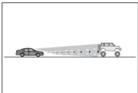
natural_image
Diagram showing a car approaching a vehicle with motion lines (no text or symbols)- If a vehicle ahead is carrying a load which protrudes past its rear bumper
- If a vehicle ahead is irregularly shaped, such as a tractor or side car
- If a vehicle ahead is a child sized bicycle, a bicycle that is carrying a large load, a bicycle ridden by more than one person, or a uniquely shaped bicycle (bicycle with a child seat, tandem bicycle, etc.)
- If a pedestrian/or the riding height of a bicyclist ahead is shorter than approximately 3.2 ft. (1 m) or taller than approximately 6.5 ft. (2 m)
- If a pedestrian/bicyclist is wearing oversized clothing (a rain coat, long skirt, etc.), making their silhouette obscure
- If a pedestrian is bending forward or squatting or bicyclist is bending forward
• If a pedestrian/bicyclist is moving fast
• If a pedestrian is pushing a stroller, wheelchair, bicycle or other vehicle - When driving in inclement weather
such as heavy rain, fog, snow or a sandstorm
- When driving through steam or smoke
- When the surrounding area is dim, such as at dawn or dusk, or while at night or in a tunnel, making a detectable object appear to be nearly the same color as its surroundings
- When driving in a place where the surrounding brightness changes suddenly, such as at the entrance or exit of a tunnel
• After the hybrid system has started the vehicle has not been driven for a certain amount of time - While making a left/right turn and for a few seconds after making a left/right turn
- While driving on a curve and for a few seconds after driving on a curve
- If your vehicle is skidding
- If the front of the vehicle is raised or lowered
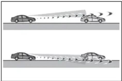
natural_image
Two cars on a road with visible sound waves, no text or symbols present- If the wheels are misaligned
- If a wiper blade is blocking the front camera
• The vehicle is being driven at extremely high speeds - When driving on a hill
- If the radar sensor or front camera is misaligned
- In some situations such as the following, sufficient braking force may not be obtained, preventing the system from performing properly:
-
If the braking functions cannot operate to their full extent, such as when the brake parts are extremely cold, extremely hot, or wet
-
If the vehicle is not properly maintained (brakes or tires are excessively worn, improper tire inflation pressure, etc.)
- When the vehicle is being driven on a gravel road or other slippery surface
■If VSC is disabled
- If VSC is disabled (→P.370), the pre-collision brake assist and pre-collision braking functions are also disabled.
●The PCS warning light will turn on and “VSC Turned Off Pre-Collision Brake System Unavailable” will be displayed on the multi-information display.
LTA (Lane Tracing Assist)
While driving on a road with clear white (yellow) lane lines, the LTA system warns the driver if the vehicle may deviate from the current lane or course*, and also can slightly operate the steering wheel to help avoid deviation from the lane or course*. Also, while the dynamic radar cruise control with full-speed range is operating, this system will operate the steering wheel to maintain the vehicle's lane position.
The LTA system recognizes white (yellow) lane lines or a course* using the front camera. Additionally, it detects preceding vehicles using the front camera and radar.
*: Boundary between asphalt and the side of the road, such as grass, soil, or a curb
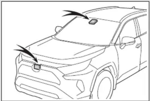
natural_image
Line drawing of a car front view with a smartphone mounted on the windshield (no text or symbols)
WARNING
■Before using LTA system
- Do not rely solely upon the LTA system. The LTA system does not automatically drive the vehicle or reduce the amount of attention that must be paid to the area in front of the vehicle. The driver must always assume full responsibility for driving safely by paying careful attention to the surrounding conditions and operating the steering wheel to correct the path of the vehicle. Also, the driver must take adequate breaks when fatigued, such as from driving for a long period of time.
●Failure to perform appropriate driving operations and pay careful attention may lead to an accident, resulting in death or serious injury.
- When not using the LTA system, use the LTA switch to turn the system off.
■ Situations unsuitable for LTA system
In the following situations, use the LTA switch to turn the system off. Failure to do so may lead to an accident, resulting in death or serious injury.
● Vehicle is driven on a road surface which is slippery due to rainy weather, fallen snow, freezing, etc.
● Vehicle is driven on a snow-covered road.
● White (yellow) lines are difficult to see due to rain, snow, fog, dust, etc.
● Vehicle is driven in a temporary lane or restricted lane due to construction work.

WARNING
● Vehicle is driven in a construction zone.
● A spare tire, tire chains, etc. are equipped.
- When the tires have been excessively worn, or when the tire inflation pressure is low.
- When your vehicle is towing a trailer or during emergency towing
■Preventing LTA system mal- functions and operations per- formed by mistake
- Do not modify the headlights or place stickers, etc. on the surface of the lights.
- Do not modify the suspension etc. If the suspension etc. needs to be replaced, contact your Toyota dealer.
- Do not install or place anything on the hood or grille. Also, do not install a grille guard (bull bars, kangaroo bar, etc.).
- If your windshield needs repairs, contact your Toyota dealer.
■Conditions in which functions may not operate properly
In the following situations, the functions may not operate properly and the vehicle may depart from its lane. Drive safely by always paying careful attention to your surroundings and operate the steering wheel to correct the path of the vehicle without relying solely on the functions.
- When the follow-up cruising display is displayed (→P.264) and the preceding vehicle changes lanes. (Your vehicle may follow the preceding vehicle and also change lanes.)
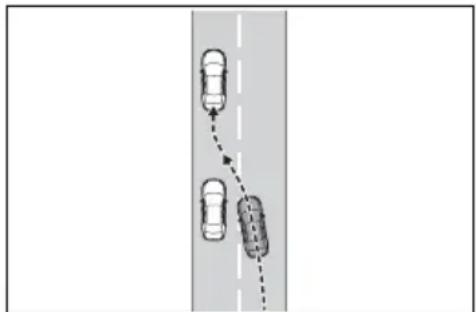
natural_image
Diagram showing a dashed road with two cars ahead of a vertical lane (no text or symbols)- When the follow-up cruising display is displayed (→P.264) and the preceding vehicle is swaying. (Your vehicle may sway accordingly and depart from the lane.)
- When the follow-up cruising display is displayed (→P.264) and the preceding vehicle departs from its lane. (Your vehicle may follow the preceding vehicle and depart from the lane.)
- When the follow-up cruising display is displayed (→P.264) and the preceding vehicle is being driven extremely close to the left/right lane line. (Your vehicle may follow the preceding vehicle and depart from the lane.)
● Vehicle is being driven around a sharp curve.

WARNING
- Objects or patterns that could be mistaken for white (yellow) lines are present on the side of the road (guardrails, reflective poles, etc.).
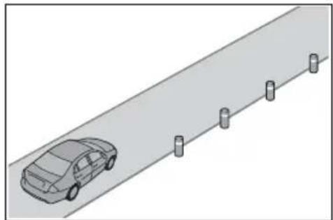
natural_image
Isometric view of a car parked on a paved road with five vertical posts (no text or symbols visible)● Vehicle is driven where the road diverges, merges, etc.
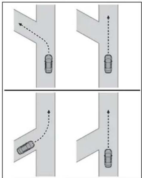
flowchart
graph TD
    A["Top Left Road"] --> B["Top Right Road"]
    B --> C["Bottom Left Road"]
    C --> D["Bottom Right Road"]
    style A fill:#f9f,stroke:#333
    style B fill:#f9f,stroke:#333
    style C fill:#f9f,stroke:#333
    style D fill:#f9f,stroke:#333
●Repair marks of asphalt, white (yellow) lines, etc. are present due to road repair.

natural_image
Diagram showing a car with motion trajectory indicated by dashed curved arrow (no text or symbols)There are shadows on the road that run parallel with, or cover, the white (yellow) lines.
●The vehicle is driven in an area without white (yellow) lines, such as in front of a tollgate or checkpoint, or at an intersection, etc.
●The white (yellow) lines are cracked, "Botts' dots", "Raised pavement marker" or stones are present.
●The white (yellow) lines cannot be seen or are difficult to see due to sand, etc.
●The vehicle is driven on a road surface that is wet due to rain, puddles, etc.
●The traffic lines are yellow (which may be more difficult to recognize than lines that are white).
● The white (yellow) lines cross over a curb, etc.
●The vehicle is driven on a bright surface, such as concrete.
- If the edge of the road is not clear or straight.
●The vehicle is driven on a surface that is bright due to reflected light, etc.
●The vehicle is driven in an area where the brightness changes suddenly, such as at the entrances and exits of tunnels, etc.
●Light from the headlights of an oncoming vehicle, the sun, etc. enters the camera.
●The vehicle is driven on a slope.
●The vehicle is driven on a road which tilts left or right, or a winding road.
●The vehicle is driven on an unpaved or rough road.

WARNING
●The traffic lane is excessively narrow or wide.
●The vehicle is extremely tilted due to carrying heavy luggage or having improper tire pressure.
●The distance to the preceding vehicle is extremely short.
●The vehicle is moving up and down a large amount due to road conditions during driving (poor roads or road seams).
- When driving in a tunnel or at night with the headlights off or when a headlight is dim due to its lens being dirty or it being misaligned.
●The vehicle is struck by a cross-wind.
●The vehicle is affected by wind from a vehicle driven in a nearby lane.
●The vehicle has just changed lanes or crossed an intersection.
● Tires which differ by structure, manufacturer, brand or tread pattern are used.
- When tires of a size other than specified are installed.
●Snow tires, etc. are equipped.
●The vehicle is being driven at extremely high speeds.
Functions included in LTA system
When the system determines that the vehicle might depart from its lane or course*, a warning is displayed on the multi-information display, and a warning buzzer will sound to alert the driver.
When the warning buzzer sounds, check the area around your vehicle and carefully operate the steering wheel to move the vehicle back to the center of the lane.
Vehicles with BSM: When the system determines that the vehicle might depart from its lane and that the possibility of a collision with an overtaking vehicle in the adjacent lane is high, the lane departure alert will operate even if the turn signals are operating.
*: Boundary between asphalt and the side of the road, such as grass, soil, or a curb
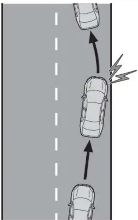
natural_image
Diagram showing three cars on a road with directional arrows indicating motion, no text or symbols present■Steering assist function
When the system determines
that the vehicle might depart from its lane or course*, the system provides assistance as necessary by operating the steering wheel in small amounts for a short period of time to keep the vehicle in its lane.
If the system detects that the steering wheel has not been operated for a fixed amount of time or the steering wheel is not being firmly gripped, a warning is displayed on the multi-information display and the function is temporarily canceled.
Vehicles with BSM: When the system determines that the vehicle might depart from its lane and that the possibility of a collision with an overtaking vehicle in the adjacent lane is high, the steering assist function will operate even if the turn signals are operating.
*: Boundary between asphalt and the side of the road, such as grass, soil, or a curb
natural_image
Top-down view of a road with multiple cars and a curved arrow indicating direction (no text or symbols)■Vehicle sway warning func- tion
When the vehicle is swaying within a lane, the warning buzzer will sound and a message will be displayed on the multi-information display to alert the driver.
natural_image
Diagram showing two cars on a road with a lightning bolt symbol indicating electric shock (no text or labels)■Lane centering function
This function is linked with dynamic radar cruise control with full-speed range and provides the required assistance by operating the steering wheel to keep the vehicle in its current lane.
When dynamic radar cruise control with full-speed range is not operating, the lane centering function does not operate.
In situations where the white (yellow) lane lines are difficult to see or are not visible, such as when in a traffic jam, this function will operate to help follow a preceding vehicle by monitoring the position of the preceding vehicle.
If the system detects that the steering wheel has not been operated for a fixed amount of time or the steering wheel is not being firmly gripped, a warning is displayed on the multi-information display and the function is temporarily canceled.
natural_image
Diagram showing three cars driving on a curved road with directional arrows (no text or symbols)Turning LTA system on
Press the LTA switch to turn the LTA system on.
The LTA indicator illuminates and a message is displayed on the multi-information display.
Press the LTA switch again to turn the LTA system off.
When the LTA system is turned on or off, operation of the LTA system continues in the same condition the next time the hybrid system is started.
text_image
LTA Turned ON Steering Assist ActiveIndications on multi-information display
text_image
A C B DA LTA indicator
The illumination condition of the indicator informs the driver of the system operation status.
Illuminated in white: LTA system is operating.
Illuminated in green: Steering wheel assistance of the steering assist function or lane centering function is operating.
Flashing in orange: Lane departure alert function is operating.
B Operation display of steering wheel operation support
Displayed when the multi-information display is switched to the driving support system information display.
Indicates that steering wheel assistance of the steering assist function or lane centering function is operating.
Both outer sides of the lane are displayed: Indicates that steering wheel assist of the lane centering function is operating.
One outer side of the lane is displayed: Indicates that steering wheel assist of the steering assist function is operating.
Both outer sides of the lane are flashing: Alerts the driver that their input is necessary to stay in the center of the lane (lane centering function).
C Follow-up cruising display
Displayed when the multi-information display is switched to the driving support system information display.
Indicates that steering assist of the lane centering function is operating by monitoring the position of a preceding vehicle.
When the follow-up cruising display is displayed, if the preceding vehicle moves, your vehicle may move in the same way. Always pay careful attention to your surroundings and operate the steering wheel as necessary to correct the path of the vehicle and ensure safety.
D Lane departure alert function display
Displayed when the multi-information display is switched to the driving support system information display.
▶ Inside of displayed lines is white
natural_image
Abstract white geometric shape with two pointed light streaks against a dark background (no text or symbols)Indicates that the system is recognizing white (yellow) lines or a course*. When the vehicle departs from its lane, the white line displayed on the side the vehicle departs from flashes orange.
▶ Inside of displayed lines is black
natural_image
Close-up of a white object with two thin white lines against a dark background, resembling a stylized lamp or abstract form (no text or symbols visible)Indicates that the system is not able to recognize white (yellow) lines or a course* or is temporarily canceled.
*: Boundary between asphalt and the side of the road, such as grass, soil, or a curb
■Operation conditions of each function
●Lane departure alert function This function operates when all of the following conditions are met.
- LTA is turned on.
- Vehicle speed is approximately 32 mph (50 km/h) or more. ^*1
- System recognizes white (yellow) lane lines or a course ^2 . (When a white [yellow] line or course ^2 is recognized on only one side, the system will operate only for the recognized side.)
- Width of traffic lane is approximately 9.8 ft. (3 m) or more.
- Turn signal lever is not operated. (Vehicles with BSM: Except when another vehicle is in the lane on the side where the turn signal was operated)
- Vehicle is not being driven around a sharp curve.
- No system malfunctions are detected. (→P.267)
*1: The function operates even if the vehicle speed is less than approximately 32 mph (50 km/h) when the lane centering function is operating.
^*2 :Boundary between asphalt and the side of the road, such as grass, soil, or a curb
●Steering assist function
This function operates when all of the following conditions are met in addition to the operation conditions for the lane departure alert function.
- Setting for "Steering Assist" in the
screen of the multi-information display is set to "ON". (→P.103)
- Vehicle is not accelerated or decelerated by a fixed amount or more.
- Steering wheel is not operated with a steering force level suitable for changing lanes.
- ABS, VSC, TRAC and PCS are not operating.
- TRAC or VSC is not turned off.
- Hands off steering wheel warning is not displayed. (→P.267)
●Vehicle sway warning function
This function operates when all of the following conditions are met.
- Setting for "Sway Warning" in the

screen of the multi-information play is set to "ON". (→P.103)
- Vehicle speed is approximately 32 mph (50 km/h) or more.
- Width of traffic lane is approximately 9.8 ft. (3 m) or more.
- No system malfunctions are detected. (→P.267)
●Lane centering function
This function operates when all of the following conditions are met.
- LTA is turned on.
- Setting for "Steering Assist" and
"Lane Center" in the screen of the multi-information display are set to "ON". (→P.103)
- This function recognizes white (yellow) lane lines or the position of a preceding vehicle (except when the preceding vehicle is small, such as a motorcycle).
- The dynamic radar cruise control with full-speed range is operating in vehicle-to-vehicle distance control mode.
- Width of traffic lane is approximately 10 to 13 ft. (3 to 4 m).
- Turn signal lever is not operated.
- Vehicle is not being driven around a sharp curve.
- No system malfunctions are detected. (→P.267)
- Vehicle does not accelerate or decelerate by a fixed amount or more.
- Steering wheel is not operated with a steering force level suitable for changing lanes.
- ABS, VSC, TRAC and PCS are not operating.
- TRAC or VSC is not turned off.
- Hands off steering wheel warning is not displayed. (→P.267)
- The vehicle is being driven in the center of a lane.
- Steering assist function is not operating.
■ Temporary cancelation of functions
- When operation conditions are no longer met, a function may be temporarily canceled. However, when the operation conditions are met again, operation of the function is automatically restored. (→P.265)
- If the operation conditions (→P.265) are no longer met while the lane centering function is operating, the buzzer may sound to indicate that the function has been temporarily canceled.
■Steering assist function/lane centering function
● Depending on the vehicle speed, lane departure situation, road conditions, etc., the driver may not feel the function is operating or the function may not operate at all.
- The steering control of the function is overridden by the driver's steering wheel operation.
- Do not attempt to test the operation of the steering assist function.
■Lane departure alert function
●The warning buzzer may be difficult to hear due to external noise, audio playback, etc.
- If the edge of the course ^* is not clear or straight, the lane departure alert function may not operate.
● Vehicles with BSM: It may not be possible for the system to determine if there is a danger of a collision with a vehicle in an adjacent lane.
- Do not attempt to test the operation of the lane departure alert function.
*: Boundary between asphalt and the side of the road, such as grass, soil, or a curb
■Hands off steering wheel warning
In the following situations, a warning message urging the driver to hold the steering wheel and the symbol shown in the illustration are displayed on the multi-information display to warn the driver. The warning stops when the system determines that the driver holds the steering wheel. Always keep your hands on the steering wheel when using this system, regardless of warnings.
natural_image
Two gray icons: a car with lane markings and a steering wheel, both on a dark background (no text or symbols)- When the system determines that the driver is driving without holding the steering wheel while the system is operating
If the driver continues to keep their hands off of the steering wheel, the buzzer sounds, the driver is warned and the function is temporarily canceled. This warning also operates in the same way when the driver continuously operates the steering wheel only a small amount.
- When the system determines that the vehicle may deviate from the lane while driving around a curve while the lane centering function is operating.
Depending on the vehicle condition and road conditions, the warning may not operate. Also, if the system determines that the vehicle is driving around a curve, warnings will occur earlier than during straight-lane driving.
- When the system determines that the driver is driving without hold-
ing the steering wheel while the steering wheel assist of the steering assist function is operating.
If the driver continues to keep their hands off of the steering wheel and the steering wheel assist is operating, the buzzer sounds and the driver is warned. Each time the buzzer sounds, the continuing time of the buzzer becomes longer.
■Vehicle sway warning function
When the system determines that the vehicle is swaying while the vehicle sway warning function is operating, a buzzer sounds and a warning message urging the driver to rest and the symbol shown in the illustration are simultaneously displayed on the multi-information display.

natural_image
Simple icon of a steaming coffee cup on a saucer, no text or symbols presentDepending on the vehicle and road conditions, the warning may not operate.
■Warning message
If the following warning message is displayed on the multi-information display and the LTA indicator illuminates in orange, follow the appropriate troubleshooting procedure. Also, if a different warning message is displayed, follow the instructions displayed on the screen.
●“LTA Malfunction Visit Your Dealer”
The system may not be operating properly. Have the vehicle inspected by your Toyota dealer.
●“LTA Unavailable”
The system is temporarily canceled
due to a malfunction in a sensor other than the front camera. Turn the LTA system off, wait for a little while, and then turn the LTA system back on.
●“LTA Unavailable at Current Speed”
The function cannot be used as the vehicle speed exceeds the LTA operation range. Drive slower.
Customization
Function settings can be changed. (→P.109)
RSA (Road Sign Assist)\*
*: If equipped
The RSA system recognizes specific road signs using the front camera to provide information to the driver via the display.
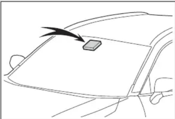
natural_image
Line drawing of a car's frontview with a small rectangular object on the windshield and an arrow pointing to it (no text or symbols)If the system judges that the vehicle is being driven over the speed limit, performing prohibited actions, etc. according to the recognized road signs, it notifies the driver through a visual notification and notification buzzer.

WARNING
■Before using the RSA
Do not rely solely upon the RSA system. RSA is a system which supports the driver by providing information, but it is not a replacement for a driver's own vision and awareness. Drive safely by always paying careful attention to the traffic rules.
Indication on the multi-information display
When the front camera recognizes a sign, the sign will be displayed on the multi-information display.
- When the driving support system information display is selected, a maximum of 3 signs can be displayed. (→P.103)
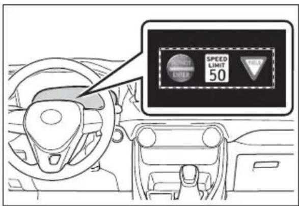
text_image
SPEED LIMIT 50 HOLD- When a tab other than the driving support system information display is selected, the following types of road signs will be displayed. (→P.103)
- Speed limit sign
- Do Not Enter sign tion is necessary)
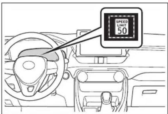
text_image
SPEED LIMIT 50If signs other than speed limit signs are recognized, they will be displayed in an overlapping stack under the current speed limit sign.
Supported types of road signs
The following types of road signs, including electronic signs and blinking signs, are recognized.
A non-official or a recently introduced traffic sign may not be recognized.
Speed limit
Do Not Enter

Stop
Yield
(Notification function
In the following situations, the RSA system will notify the driver.
- When the vehicle speed exceeds the speed notification threshold of the speed limit sign displayed, the sign display will be emphasized and a buzzer will sound.
- When the RSA system recog-
nizes a do not enter sign and determines that your vehicle has entered a no-entry area, the displayed sign will flash and a buzzer will sound.
Depending on the situation, a notification function may not operate properly.
Setting procedure
→P.109
■Automatic turn-off of RSA sign display
In the following situations, displayed speed limit sign and/or do not enter signs will stop being displayed automatically:
●No sign has been recognized for a certain distance.
●The road changes due to a left or right turn, etc.
In the following situations, stop and yield signs will stop being displayed automatically:
●The system determines that your vehicle has passed the sign.
●The road changes due to a left or right turn, etc.
■ Conditions in which the function may not operate or detect correctly
In the following situations, RSA does not operate normally and may not recognize signs, display the incorrect sign, etc. However, this does not indicate a malfunction.
●The front camera is misaligned due to a strong impact being applied to the sensor, etc.
- Dirt, snow, stickers, etc. are on the windshield near the front camera.
● In inclement weather such as heavy rain, fog, snow or sand storms
●Light from an oncoming vehicle,
the sun, etc. enters the front camera.
●The sign is dirty, faded, tilted or bent, and if an electronic sign, the contrast is poor.
● All or part of the sign is hidden by the leaves of a tree, a pole, etc.
●The sign is only visible to the front camera for a short amount of time.
●The driving scene (turning, lane change, etc.) is judged incorrectly.
- If a sign not appropriate for the currently traveled lane, but the sign exists directly after a freeway branches, or in an adjacent lane just before merging.
●Stickers are attached to the rear of the preceding vehicle.
●A sign resembling a system compatible sign is recognized.
- Side road speed signs may be detected and displayed (if positioned in sight of the front camera) while the vehicle is traveling on the main road.
●Roundabout exit road speed signs may be detected and displayed (if positioned in sight of the front camera) while traveling on a roundabout.
●The front of the vehicle is raised or lowered due to the carried load.
●The surrounding brightness is not sufficient or changes suddenly.
- When a sign intended for trucks, etc. is recognized.
●The speed information displayed on the meter and on the navigation system may be different due to the navigation system using map data.
■Speed limit sign display
If the power switch was last turned off while a speed limit sign was displayed on the multi-information display, the same sign displays again when the power switch is turned to ON.
If "RSA Malfunction Visit Your Dealer" is shown
The system may be malfunctioning. Have the vehicle inspected by your Toyota dealer.
Customization
Some functions can be customized. (Customizable features: →P.109)
Dynamic radar cruise control with full-speed range
In vehicle-to-vehicle distance control mode, the vehicle automatically accelerates, decelerates and stops to match the speed changes of the preceding vehicle even if the accelerator pedal is not depressed. In constant speed control mode, the vehicle runs at a fixed speed.
Use the dynamic radar cruise control with full-speed range on freeways and highways.
● Vehicle-to-vehicle distance control mode ( P.274)
- Constant speed control mode (→P.279)
System Components
■Meter display
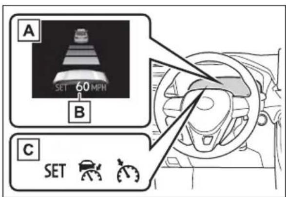
text_image
A SET 60 MPH B C SETA Multi-information display
B Set speed
C Indicators
Operation switches
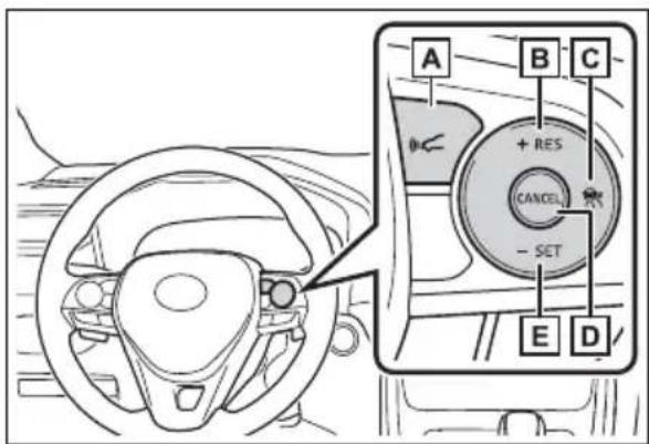
text_image
A B C + RES CANCEL - SET E DA Vehicle-to-vehicle distance switch
B “+RES” switch
Cruise control main switch
D Cancel switch
E “-SET” switch

WARNING
■Before using dynamic radar cruise control with full-speed range
●Driving safely is the sole responsibility of the driver. Do not rely solely on the system, and drive safely by always paying careful attention to your surroundings.
The dynamic radar cruise control with full-speed range provides driving assistance to reduce the driver's burden. However, there are limitations to the assistance provided.
Read the following conditions carefully. Do not overly rely on this system and always drive carefully.
- When the sensor may not be correctly detecting the vehicle ahead: P.281
- Conditions under which the vehicle-to-vehicle distance control mode may not function correctly: →P.281
- Set the speed appropriately depending on the speed limit, traffic flow, road conditions, weather conditions, etc. The driver is responsible for checking the set speed.
● Even when the system is functioning normally, the condition of the preceding vehicle as detected by the system may differ from the condition observed by the driver. Therefore, the driver must always remain alert, assess the danger of each situation and drive safely. Relying solely on this system or assuming the system ensures safety while driving can lead to an accident, resulting in death or serious injury.
- Switch the dynamic radar cruise control with full-speed range setting to off, using the cruise control main switch when not in use.

WARNING
■ Cautions regarding the driving assist systems
Observe the following precautions, as there are limitations to the assistance provided by the system. Failure to do so may cause an accident resulting in death or serious injury.
● Assisting the driver to measure following distance
The dynamic radar cruise control with full-speed range is only intended to help the driver in determining the following distance between the driver's own vehicle and a designated vehicle traveling ahead. It is not a mechanism that allows careless or inattentive driving, and it is not a system that can assist the driver in low-visibility conditions.
It is still necessary for driver to pay close attention to the vehicle's surroundings.
●Assisting the driver to judge proper following distance
The dynamic radar cruise control with full-speed range determines whether the following distance between the driver's own vehicle and a designated vehicle traveling ahead is within a set range. It is not capable of making any other type of judgement. Therefore, it is absolutely necessary for the driver to remain vigilant and to determine whether or not there is a possibility of danger in any given situation.
●Assisting the driver to operate the vehicle
The dynamic radar cruise control with full-speed range does not include functions which will prevent or avoid collisions with vehicles ahead of your vehicle.
Therefore, if there is ever any possibility of danger, the driver must take immediate and direct control of the vehicle and act appropriately in order to ensure the safety of all involved.
■Situations unsuitable for dynamic radar cruise control with full-speed range
Do not use dynamic radar cruise control with full-speed range in any of the following situations. Doing so may result in inappropriate speed control and could cause an accident resulting in death or serious injury.
●Roads where there are pedestrians, cyclists, etc.
In heavy traffic
● On roads with sharp bends
●On winding roads
● On slippery roads, such as those covered with rain, ice or snow
● On steep downhills, or where there are sudden changes between sharp up and down gradients
Vehicle speed may exceed the set speed when driving down a steep hill.
● At entrances to freeways and highways

WARNING
- When weather conditions are bad enough that they may prevent the sensors from detecting correctly (fog, snow, sandstorm, heavy rain, etc.)
- When there is rain, snow, etc. on the front surface of the radar or front camera
● In traffic conditions that require frequent repeated acceleration and deceleration - When your vehicle is towing a trailer or during emergency towing
- When an approach warning buzzer is heard often
Driving in vehicle-to-vehicle distance control mode
This mode employs a radar to detect the presence of vehicles up to approximately 328 ft. (100 m) ahead, determines the current vehicle-to-vehicle following distance, and operates to maintain a suitable following distance from the vehicle ahead. The desired vehicle-to-vehicle distance can also be set by operating the vehicle-to-vehicle distance switch.
When driving on downhill slopes, the vehicle-to-vehicle distance may become shorter.
A
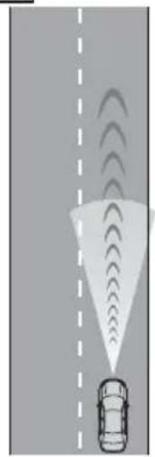
natural_image
Diagram showing a car emitting signal waves from a road, with no text or symbols present.B
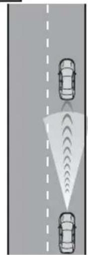
natural_image
Diagram showing two cars ahead of a road with traffic light dispersion (no text or symbols)
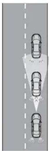
natural_image
Top-down diagram of three cars on a road with dashed lane markings (no text or symbols)C
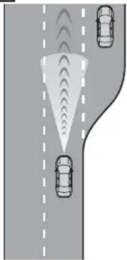
natural_image
Diagram showing three cars on a road with traffic signals and directional arrows (no text or symbols)A Example of constant speed cruising
When there are no vehicles ahead
The vehicle travels at the speed set by the driver.
B Example of deceleration cruising and follow-up cruising
When a preceding vehicle driving slower than the set speed appears
When a vehicle is detected running ahead of you, the system automatically decelerates your vehicle. When a greater reduction in vehicle speed is necessary, the system applies the brakes (the stop lights will come on at this time). The system will respond to changes in the speed of the vehicle ahead in order to maintain the vehicle-to-vehicle distance set by the driver. Approach warning warns you when the system cannot decelerate sufficiently to prevent your vehicle from closing in on the vehicle ahead.
When the vehicle ahead of you stops, your vehicle will also stop (vehicle is stopped by system control). After the vehicle ahead starts off, pressing the “+RES” switch or depressing the accelerator pedal (start-off operation) will resume follow-up cruising. If the start-off operation is not performed, system control continues to keep your vehicle stopped.
When the turn signal lever is operated and your vehicle moves to an over-taking lane while driving at 50 mph (80 km/h) or more, the vehicle will accelerate to help to overtake a passing vehicle.
The system's identification of what is an overtaking lane may be determined solely based on the location of the steering wheel in the vehicle (left side driver position versus right side driver position.) If the vehicle is driven to a region where the overtaking lane is on a different side from where the vehicle is normally driven, the vehicle may accelerate when the turn signal lever is operated in the opposite direction to the overtaking lane (e.g., if the driver normally operates the vehicle in a region where the overtaking lane is to the right but then drives to a region where the overtaking lane is to the left, the vehicle may accelerate when the right turn signal is activated).
c Example of acceleration
When there are no longer any preceding vehicles driving slower than the set speed
The system accelerates until the set speed is reached. The system then returns to constant speed cruising.
Setting the vehicle speed (vehicle-to-vehicle distance control mode)
1 Press the cruise control main
switch to activate the cruise control.
Dynamic radar cruise control indicator will come on and a message will be displayed on the multi-information display. Press the switch
again to deactivate the cruise control.
If the cruise control main switch is pressed and held for 1.5 seconds or more, the system turns on in constant speed control mode. (→P.279)
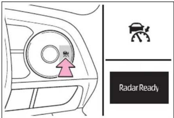
text_image
Radar Ready2 Accelerate or decelerate, with accelerator pedal operation, to the desired vehicle speed (at or above approximately 20 mph [30 km/h]) and press the “-SET” switch to set the speed.
Cruise control "SET" indicator will come on.
The vehicle speed at the moment the switch is released becomes the set speed.
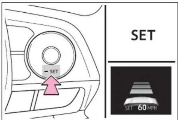
text_image
SET - SET SET 60 MPHAdjusting the set speed
To change the set speed, press the “+RES” or “-SET” switch until the desired set speed is
displayed.
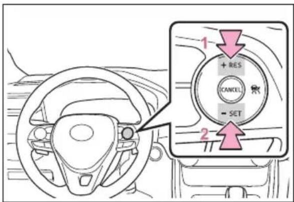
text_image
1 + RES CANCEL - SET 21 Increases the speed (Except when the vehicle has been stopped by system control in vehicle-to-vehicle distance control mode)
2 Decreases the speed
Fine adjustment: Press the switch. Large adjustment: Press and hold the switch to change the speed, and release when the desired speed is reached.
In the vehicle-to-vehicle distance control mode, the set speed will be increased or decreased as follows:
For the U.S. mainland and Hawaii
Fine adjustment: By 1 mph (1.6 km/h) ^1 or 1 km/h (0.6 mph) ^2 each time the switch is pressed
Large adjustment: Increases or decreases in 1 mph (1.6 km/h) ^1 or 1 km/h (0.6 mph) ^2 increments for as long as the switch is held
▶ Except for the U.S. mainland and Hawaii
Fine adjustment: By 1 mph (1.6 km/h) ^1 or 1 km/h (0.6 mph) ^2 each time the switch is pressed
Large adjustment: Increases or decreases in 5 mph (8 km/h) ^1 or 5 km/h (3.1 mph) ^2 increments for as long as the switch is held
In the constant speed control mode ( P.279), the set speed will be increased or decreased as follows:
Fine adjustment: By 1 mph (1.6 km/h) ^1 or 1 km/h (0.6 mph) ^2 each time the switch is pressed
Large adjustment: The speed will continue to change while the switch is held.
*1: When the set speed is shown in "MPH"
*2: When the set speed is shown in "km/h"
Changing the vehicle-to-vehicle distance (vehicle-to-vehicle distance control mode)
Pressing the switch changes the vehicle-to-vehicle distance as follows:
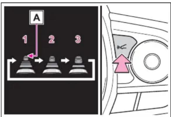
text_image
A 1 2 31 Long
2 Medium
3 Short
The vehicle-to-vehicle distance is set automatically to long mode when the power switch is turned to ON.
If a vehicle is running ahead of you, the preceding vehicle mark A will also be displayed.
Vehicle-to-vehicle distance settings (vehicle-to-vehicle distance control mode)
Select a distance from the table below. Note that the distances shown correspond to a vehicle speed of 50 mph (80 km/h).
Vehicle-to-vehicle distance increases/decreases in accordance with vehicle speed. When the vehicle is stopped by system control, the vehicle stops at a certain vehicle-to-vehicle distance depending on the situation.
| Distance options | Vehicle-to-vehicle distance |
| Long | Approximately 160 ft. (50 m) |
| Medium | Approximately 130 ft. (40 m) |
| Short | Approximately 100 ft. (30 m) |
Resuming follow-up cruising when the vehicle has been stopped by sys- tem control (vehicle-to- vehicle distance control mode)
After the vehicle ahead of you starts off, press the “+RES” switch.
Your vehicle will also resume follow-up cruising if the accelerator pedal is depressed after the vehicle ahead of you starts off.
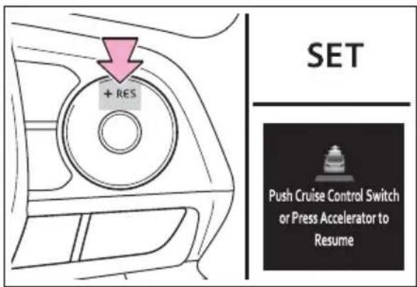
text_image
+ RES SET Push Cruise Control Switch or Press Accelerator to ResumeCanceling and resuming the speed control
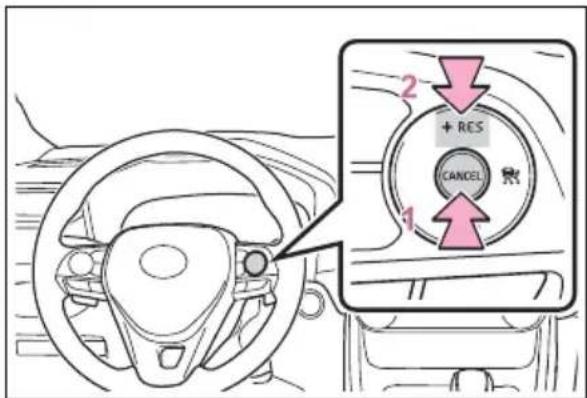
text_image
2 + RES CANCEL 11 Pressing the cancel switch cancels the speed control.
The speed control is also canceled when the brake pedal is depressed. (When the vehicle has been
stopped by system control, depressing the brake pedal does not cancel the setting.)
2 Pressing the “+RES” switch resumes the cruise control and returns vehicle speed to the set speed.
Approach warning (vehicle-to-vehicle distance control mode)
When your vehicle is too close to a vehicle ahead, and sufficient automatic deceleration via the cruise control is not possible, the display will flash and the buzzer will sound to alert the driver. An example of this would be if another driver cuts in front of you while you are following a vehicle. Depress the brake pedal to ensure an appropriate vehicle-to-vehicle distance.
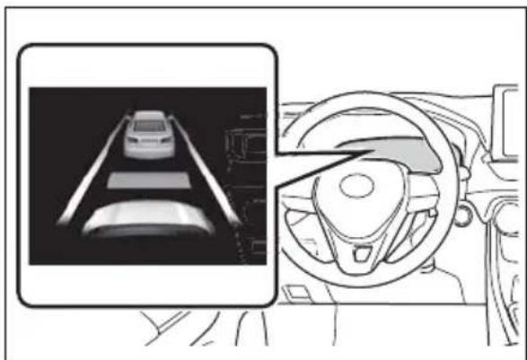
natural_image
Diagram showing a car interior with steering wheel and dashboard, alongside a 3D rendered road view (no text or symbols)■Warnings may not occur when
In the following instances, warnings may not occur even when the vehicle-to-vehicle distance is small.
- When the speed of the pre-
ceding vehicle matches or exceeds your vehicle speed
- When the preceding vehicle is traveling at an extremely slow speed
- Immediately after the cruise control speed was set
- When depressing the accelerator pedal
Selecting constant speed control mode
When constant speed control mode is selected, your vehicle will maintain a set speed without controlling the vehicle-to-vehicle distance. Select this mode only when vehicle-to-vehicle distance control mode does not function correctly due to a dirty radar, etc.
1 With the cruise control off, press and hold the cruise control main switch for 1.5 seconds or more.
Immediately after the switch is pressed, the dynamic radar cruise control indicator will come on. Afterwards, it switches to the cruise control indicator.
Switching to constant speed control mode is only possible when operating the switch with the cruise con-
trol off.
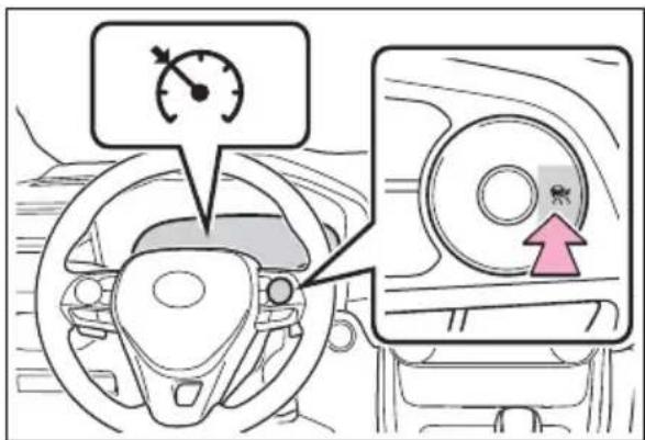
text_image
Diagram showing car steering wheel and dashboard with speedometer and directional arrow indicator2 Accelerate or decelerate, with accelerator pedal operation, to the desired vehicle speed (at or above approximately 20 mph [30 km/h]) and press the "-SET" switch to set the speed.
Cruise control "SET" indicator will come on.
The vehicle speed at the moment the switch is released becomes the set speed.
Adjusting the speed setting: →P.276
Canceling and resuming the speed setting: →P.278
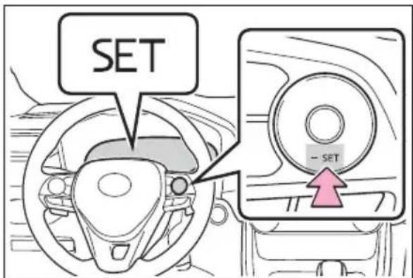
text_image
SET - SET■ Dynamic radar cruise control with full-speed range can be set when
●The shift lever is in D.
●The desired set speed can be set when the vehicle speed is approximately 20 mph (30 km/h) or more.
(However, when the vehicle speed is set while driving at below approximately 20 mph [30 km/h], the set speed will be set to approximately 20 mph [30 km/h].)
■Accelerating after setting the vehicle speed
The vehicle can accelerate by operating the accelerator pedal. After accelerating, the set speed resumes. However, during vehicle-to-vehicle distance control mode, the vehicle speed may decrease below the set speed in order to maintain the distance to the preceding vehicle.
■When the vehicle stops while follow-up cruising
- Pressing the “+RES” switch while the vehicle ahead stops will resume follow-up cruising if the vehicle ahead starts off within approximately 3 seconds after the switch is pressed.
- If the vehicle ahead starts off within 3 seconds after your vehicle stops, follow-up cruising will be resumed.
■Automatic cancelation of vehicle-to-vehicle distance control mode
Vehicle-to-vehicle distance control mode is automatically canceled in the following situations.
●VSC is activated.
●TRAC is activated for a period of time.
- When the VSC or TRAC system is turned off.
●The sensor cannot detect correctly because it is covered in some way.
●Pre-collision braking is activated.
●The parking brake is operated.
●The vehicle is stopped by system control on a steep incline.
●The following are detected when the vehicle has been stopped by
system control:
- The driver is not wearing a seat belt.
- The driver's door is opened.
- The vehicle has been stopped for about 3 minutes
If vehicle-to-vehicle distance control mode is automatically canceled for any reasons other than the above, there may be a malfunction in the system. Contact your Toyota dealer.
■Automatic cancelation of constant speed control mode
Constant speed control mode is automatically canceled in the following situations:
●Actual vehicle speed is more than approximately 10 mph (16 km/h) below the set vehicle speed.
●Actual vehicle speed falls below approximately 20 mph (30 km/h).
●VSC is activated.
●TRAC is activated for a period of time.
- When the VSC or TRAC system is turned off.
●Pre-collision braking is activated. If constant speed control mode is automatically canceled for any reasons other than the above, there may be a malfunction in the system. Contact your Toyota dealer.
Brake operation
A brake operation sound may be heard and the brake pedal response may change, but these are not malfunctions.
■Warning messages and buzzers for dynamic radar cruise control with full-speed range
Warning messages and buzzers are used to indicate a system malfunction or to inform the driver of the need for caution while driving. If a warning message is shown on the multi-information display, read the
message and follow the instructions. (→P.248, 654)
■When the sensor may not be correctly detecting the vehicle ahead
In the case of the following and depending on the conditions, operate the brake pedal when deceleration of the system is insufficient or operate the accelerator pedal when acceleration is required.
As the sensor may not be able to correctly detect these types of vehicles, the approach warning ( P.278) may not be activated.
● Vehicles that cut in suddenly
● Vehicles traveling at low speeds
● Vehicles that are not moving in the same lane
● Vehicles with small rear ends (trailers with no load on board, etc.)
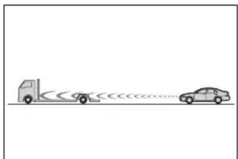
natural_image
Diagram showing two vehicles with a truck and a car, connected by a road with circular traffic indicators (no text or symbols)●Motorcycles traveling in the same lane
- When water or snow thrown up by the surrounding vehicles hinders the detecting of the sensor
- When your vehicle is pointing upwards (caused by a heavy load in the luggage compartment, etc.)
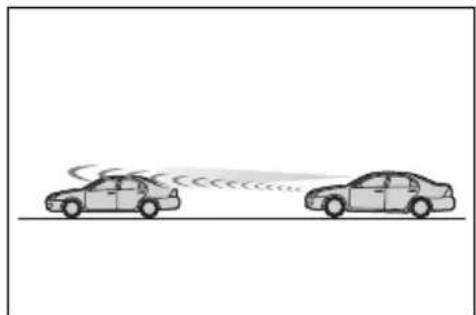
natural_image
Two cars on a road with a curved speedometer, no text or symbols present●Preceding vehicle has an
extremely high ground clearance
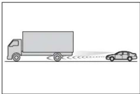
natural_image
Illustration of a truck and a car on a road with sound waves (no text or symbols)Conditions under which the vehicle-to-vehicle distance control mode may not function correctly
In the case of the following conditions, operate the brake pedal (or accelerator pedal, depending on the situation) as necessary.
As the sensor may not be able to correctly detect vehicles ahead, the system may not operate properly.
- When the road curves or when the lanes are narrow
natural_image
Three curved road scenarios showing cars on different surfaces with motion indicators (no text or symbols)- When steering wheel operation or your position in the lane is unstable
natural_image
Two identical road scenarios showing cars emitting sound waves from a central road (no text or symbols)●When the vehicle ahead of you decelerates suddenly
- When driving on a road surrounded by a structure, such as in a tunnel or on a bridge
●While the vehicle speed is
decreasing to the set speed after the vehicle accelerates by depressing the accelerator pedal
BSM (Blind Spot Monitor)\*
*: If equipped
The Blind Spot Monitor is a system that has 2 functions:
● The BSM (Blind Spot Monitor) function
Assists the driver in making a decision when changing lanes
● The RCTA (Rear Cross Traffic Alert) function
Assists the driver when back-
ing up
These functions use the same sensors.

WARNING
■ Cautions regarding the use of the BSM function
The driver is solely responsible for safe driving. Always drive safely, taking care to observe your surroundings.
The BSM function is a supplementary function which alerts the driver that a vehicle is in a blind spot of the outside rear view mirrors or is approaching rapidly from behind into a blind spot. Do not overly rely on the BSM function. As the function cannot judge if it is safe to change lanes, over reliance could lead to an accident resulting in death or serious injury.
As the system may not function correctly under certain conditions, the driver's own visual confirmation of safety is necessary.

WARNING
■ Cautions regarding the use of the RCTA function
The driver is solely responsible for safe driving. Always drive safely, taking care to observe your surroundings.
The RCTA function is only a supplementary function which alerts the driver that a vehicle is approaching from the right or left at the rear of the vehicle. As the RCTA function may not function correctly under certain conditions, the driver's own visual confirmation of safety is necessary.
Over reliance on this function may lead to an accident resulting death or serious injury.
System components
Turning the BSM function/RCTA function on/off.
B Outside rear view mirror indi-
cators
BSM function:
When a vehicle is detected in a blind spot of the outside rear view mirrors or approaching rapidly from behind into a blind spot, the outside rear view mirror indicator on the detected side will illuminate. If the turn signal lever is operated toward the detected side, the outside rear view mirror indicator will flash.
RCTA function:
When a vehicle approaching from the right or left at the rear of the vehicle is detected, both outside rear view mirror indicators will flash.
C BSM indicator/RCTA OFF indicator
When the Blind Spot Monitor is enabled, the BSM indicator illuminates.
When the RCTA function is disabled, the RCTA OFF indicator illuminates.
D Monitor screen display (RCTA function only)
If a vehicle approaching from the right or left at the rear of the vehicle is detected, the RCTA icon (→P.289) for the detected side will be displayed.
E RCTA buzzer (RCTA function only)
If a vehicle approaching from the right or left at the rear of the vehicle is detected, a buzzer will sound from behind the rear seat.
Turning the BSM function/RCTA function on/off
The BSM function and the RCTA function can be
enabled/disabled on the screen of the multi-information display. (→P.109)
■ Outside rear view mirror indicators visibility
In strong sunlight, the outside rear view mirror indicator may be difficult to see.
■Hearing the RCTA buzzer
The RCTA buzzer may be difficult to hear over loud noises such as high audio volume.
When “Blind Spot Monitor Unavailable” or “Rear Cross Traffic Alert Unavailable” is shown on the multi-information display
The sensor voltage has become
■Certification for the Blind Spot Monitor
For vehicles sold in the U.S.A., Hawaii, American Samoa, Guam, Saipan and Puerto Rico
FCC ID: HYQDNSRR004
NOTE:
This device complies with part 15 of the FCC Rules. Operation is subject to the following two conditions: (1) This device may not cause harmful interference, and (2) this device must accept any interference received, including interference that may cause undesired operation.
FCC WARNING:
Changes or modifications not expressly approved by the party responsible for compliance could void the user's authority to operate the equipment.
abnormal, or water, snow, mud, etc., may be built up in the vicinity of the sensor area of the rear bumper. (→P.285)
Removing the water, snow, mud, etc., from the vicinity of the sensor area should return it to normal.
Also, the sensor may not function normally when used in extremely hot or cold weather.
When “Blind Spot Monitor System Malfunction Visit Your Dealer” or “Rear Cross Traffic Alert Malfunction Visit Your Dealer” is shown on the multi-information display
There may be a sensor malfunction or misaligned. Have the vehicle inspected at a Toyota dealer.
Customization
Some functions can be customized. (→P.109)
For vehicles sold in Canada
NOTE:
This device complies with Industry Canada's RSS-310. Operation is subject to the condition that this device must not cause harmful interference and must accept any interference, including interference that may cause undesired operation of the device.
24.05 to 24.25 GHz
250 mV/m or less @ 3m
NOTE:
250 mV/m or less @ 3m

WARNING
■Handling the radar sensor
Blind Spot Monitor sensors are installed inside the left and right sides of the rear bumper respectively. Observe the following to ensure the Blind Spot Monitor can function correctly.
natural_image
Line drawing of a car's front bumper and side bumper with directional arrows indicating movement (no text or symbols)- Keep the sensors and the surrounding areas on the rear bumper clean at all times. If a sensor or its surrounding area on the rear bumper is dirty or covered with snow, the Blind Spot Monitor may not operate and a warning message (→P.284) will be displayed. In this situation, clear off the dirt or snow and drive the vehicle with the operation conditions of the BSM function (→P.287) satisfied for approximately 10 minutes. If the warning message does not disappear, have the vehicle inspected by your Toyota dealer.
- Do not subject a sensor or its surrounding area on the rear bumper to a strong impact. If a sensor is moved even slightly off position, the system may malfunction and vehicles may not be detected correctly. In the following situations, have your vehicle inspected by your Toyota dealer.
• A sensor or its surrounding area is subject to a strong impact.

WARNING
- If the surrounding area of a sensor is scratched or dented, or part of them has become disconnected.
- Do not disassemble the sensor.
- Do not attach accessories, stickers (including transparent stickers), aluminum tape, etc. to a sensor or its surrounding area on the rear bumper.
- Do not modify the sensor or surrounding area on the rear bumper.
- If a sensor or the rear bumper needs to be removed/installed or replaced, contact your Toyota dealer.
- Do not paint the rear bumper any color other than an official Toyota color.
The Blind Spot Monitor function
■ Vehicles that can be detected by the Blind Spot Monitor
The BSM function uses radar sensors to detect the following vehicles traveling in adjacent lanes and advises the driver of the presence of such vehicles via the indicators on the outside rear view mirrors.
text_image
A BA Vehicles that are traveling in areas that are not visible using the outside rear view mirrors (the blind spots)
B Vehicles that are approaching rapidly from behind in areas that are not visible using the outside rear view mirrors (the blind spots)
■The BSM function detection areas
The areas that vehicles can be detected in are outlined below.
text_image
A B C DThe range of each detection area is:
A Approximately 1.6 ft. (0.5 m) to 11.5 ft. (3.5 m) from either side of the vehicle
The area between the side of the vehicle and 1.6 ft. (0.5 m) from the side of the vehicle cannot be detected.
B Approximately 3.3 ft. (1 m) forward of the rear bumper
C Approximately 9.8 ft. (3 m) from the rear bumper
D Approximately 9.8 ft. (3 m) to 197 ft. (60 m) from the rear bumper
The greater the difference in speed between your vehicle and the detected vehicle is, the farther away the vehicle will be detected, causing the outside rear view mirror indicator to illuminate or flash.
■The BSM function is operational when
The BSM function is operational when all of the following conditions are met:
●The BSM function is on.
●The shift lever is in a position other than R.
●The vehicle speed is greater than approximately 10 mph (16 km/h).
■The BSM function will detect a vehicle when
The BSM function will detect a vehicle present in the detection area in the following situations:
●A vehicle in an adjacent lane overtakes your vehicle.
- You overtake a vehicle in an adjacent lane slowly.
●Another vehicle enters the detection area when it changes lanes.
■Conditions under which the BSM function will not detect a vehicle
The BSM function is not designed to detect the following types of vehicles and/or objects:
● Small motorcycles, bicycles, pedestrians, etc.*
● Vehicles traveling in the opposite direction
●Guardrails, walls, signs, parked vehicles and similar stationary objects*
- Following vehicles that are in the same lane*
● Vehicles traveling 2 lanes away from your vehicle *
● Vehicles which are being over-taken rapidly by your vehicle
*: Depending on the conditions, detection of a vehicle and/or object may occur.
■ Conditions under which the BSM function may not function correctly
●The BSM function may not detect vehicles correctly in the following situations:
- When the sensor is misaligned due to a strong impact to the sensor or its surrounding area
- When mud, snow, ice, a sticker, etc. is covering the sensor or surrounding area on the rear bumper
- When driving on a road surface that is wet with standing water during bad weather, such as heavy rain, snow, or fog
- When multiple vehicles are approaching with only a small gap between each vehicle
- When the distance between your vehicle and a following vehicle is short
- When there is a significant difference in speed between your vehicle and the vehicle that enters the detection area
- When the difference in speed between your vehicle and another vehicle is changing
- When a vehicle enters a detection area traveling at about the same speed as your vehicle
- As your vehicle starts from a stop, a vehicle remains in the detection area
- When driving up and down consecutive steep inclines, such as hills, dips in the road, etc.
- When driving on roads with sharp bends, consecutive curves, or uneven surfaces
- When vehicle lanes are wide, or when driving on the edge of a lane, and the vehicle in an adjacent lane is far away from your vehicle
- When an accessory (such as a bicycle carrier) is installed to the rear of the vehicle
- When there is a significant difference in height between your vehicle and the vehicle that enters the detection area
- Immediately after the BSM func-
tion/RCTA function are turned on
- When towing a trailer
●Instances of the BSM function unnecessarily detecting a vehicle and/or object may increase in the following situations: - When the sensor is misaligned due to a strong impact to the sensor or its surrounding area
- When the distance between your vehicle and a guardrail, wall, etc. that enters the detection area is short
- When driving up and down consecutive steep inclines, such as hills, dips in the road, etc.
- When vehicle lanes are narrow, or when driving on the edge of a lane, and a vehicle traveling in a lane other than the adjacent lanes enters the detection area
- When driving on roads with sharp bends, consecutive curves, or uneven surfaces
- When the tires are slipping or spinning
- When the distance between your vehicle and a following vehicle is short
- When an accessory (such as a bicycle carrier) is installed to the rear of the vehicle
- When the vehicle throws up water or snow behind.
The Rear Cross Traffic Alert function (if equipped)
■Operation of the RCTA function
The RCTA function uses radar sensors to detect vehicles approaching from the right or left at the rear of the vehicle and alerts the driver of the presence of such vehicles by flashing the outside rear view mirror indica-
tors and sounding a buzzer.

flowchart
graph TD
    A1["Car A"] --> B1["B"]
    B1 --> C1["Car B"]
    C1 --> D1["Car A"]
    D1 --> E1["Car B"]
    E1 --> F1["Car A"]
    style A1 fill:#f9f,stroke:#333
    style B1 fill:#ccf,stroke:#333
    style C1 fill:#cfc,stroke:#333
    style D1 fill:#fcc,stroke:#333
    style E1 fill:#cff,stroke:#333
A Approaching vehicles
B Detection areas
■RCTA icon display (if equipped)
When a vehicle approaching from the right or left at the rear of the vehicle is detected, the following will be displayed on the navigation system (if equipped) or multimedia system (if equipped) screen.
- When the Toyota parking assist monitor (if equipped) is displayed
natural_image
Diagram of a car with motion arrows indicating speed or flow (no text or symbols)- When the panoramic view monitor (if equipped) is displayed
natural_image
Diagram showing a structural frame being lifted by an arrow, and a car on a ramp with motion arrows (no text or symbols)The RCTA function is malfunctioning ( P.284)
■The RCTA function detection areas
The areas that vehicles can be detected in are outlined below.
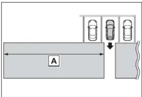
text_image
AThe buzzer can alert the driver of faster vehicles approaching from farther away.
Example:
| Approaching vehicle | Speed | Approximate alert distance |
| Fast | 18 mph (28 km/h) | 65 ft. (20 m) |
| Slow | 5 mph (8 km/h) | 18 ft. (5.5 m) |
■The RCTA function is operational when
The RCTA function operates when all of the following conditions are met:
●The RCTA function is on.
●The shift lever is in R.
●The vehicle speed is less than approximately 5 mph (8 km/h).
●The approaching vehicle speed is between approximately 5 mph (8 km/h) and 17 mph (28 km/h).
■Setting the buzzer volume
The buzzer volume can be adjusted on the multi-information display. (→P.109)
■Conditions under which the RCTA function will not detect a vehicle
The RCTA function is not designed to detect the following types of vehicles and/or objects.
● Vehicles approaching from directly behind
● Vehicles backing up in a parking space next to your vehicle
● Vehicles that the sensors cannot detect due to obstructions
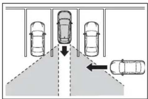
text_image
Diagram showing parking garage with cars and directional arrows indicating movement or clearance●Guardrails, walls, signs, parked vehicles and similar stationary objects*
● Small motorcycles, bicycles, pedestrians, etc. *
● Vehicles moving away from your vehicle
● Vehicles approaching from the parking spaces next to your vehi-
cle*
*: Depending on conditions, detection of a vehicle and/or object may occur.
■ Conditions under which the RCTA function may not function correctly
●The RCTA function may not detect vehicles correctly in the following situations:
- When the sensor is misaligned due to a strong impact to the sensor or its surrounding area
- When mud, snow, ice, a sticker, etc. is covering the sensor or surrounding area on the rear bumper
- When driving on a road surface that is wet with standing water during bad weather, such as heavy rain, snow, or fog
- When multiple vehicles are approaching with only a small gap between each vehicle
- When a vehicle is approaching at high speed
- When parking on a steep incline, such as hills, a dip in the road, etc.
- When an accessory (such as a bicycle carrier) is installed to the rear of the vehicle
- When backing up on a slope with a sharp change in grade
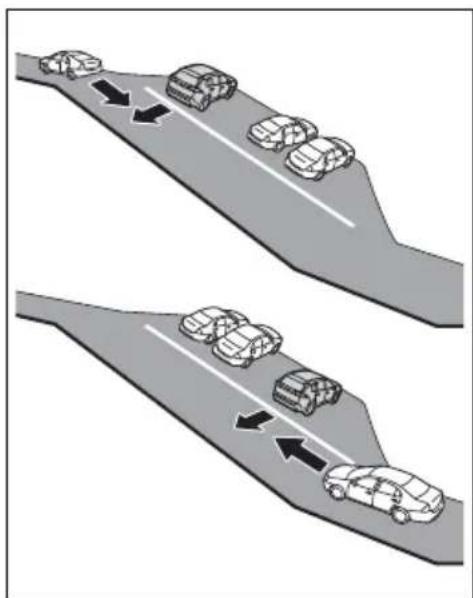
natural_image
Diagram showing two lanes with cars moving on a road, indicated by arrows (no text or symbols)- When backing out of a shallow angle parking spot
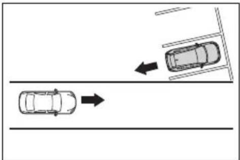
natural_image
Top-down diagram of two cars on a road with directional arrows indicating movement (no text or symbols)- Immediately after the RCTA function is turned on
- Immediately after the hybrid system is started with the RCTA function on
- When towing a trailer
- When the sensors cannot detect a vehicle due to obstructions
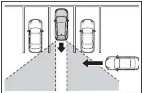
text_image
Diagram showing parking lane with cars and directional arrows indicating movement or flow●Instances of the RCTA function unnecessary detecting a vehicle and/or object may increase in the following situations:
- When a vehicle passes by the side of your vehicle
- When the parking space faces a street and vehicles are being driven on the street
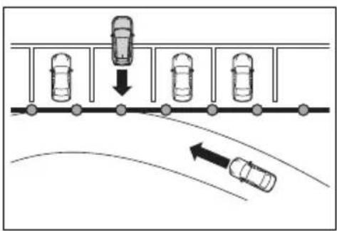
text_image
Diagram showing car parking and road collision with directional arrows indicating movement- When the distance between your vehicle and metal objects, such as a guardrail, wall, sign, or parked vehicle, which may reflect electrical waves toward the rear of the vehicle, is short
- When an accessory (such as a bicycle carrier) is installed to the rear of the vehicle
Intuitive parking assist\*
*: If equipped
The distance from your vehicle to objects, such as a wall, when parallel parking or maneuvering into a garage is measured by the sensors and communicated via the multi-information display, navigation system or multimedia system screen and a buzzer. Always check the surrounding area when using this system.
System components
■ Location and types of sensors
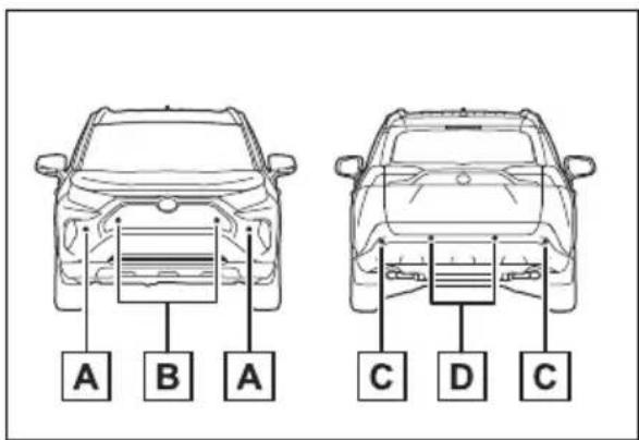
text_image
A B A C D CA Front corner sensors
B Front center sensors
C Rear corner sensors
D Rear center sensors
■Display (Multi-information display)
When the sensors detect an object, such as a wall, a graphic
is shown on the multi-information display depending on the position and distance to the object.
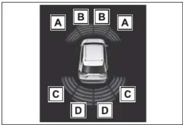
text_image
A B B A C C D DA Front corner sensor detection
B Front center sensor detection ^1
C Rear corner sensor detection ^2
D Rear center sensor detection ^4
*1: Displayed when the shift lever is in a driving position
*2: Displayed when the shift lever is in R
■Display (Audio system screen)
When the sensors detect an object, such as a wall, a graphic is shown on the navigation system (if equipped) or multimedia system (if equipped) screen depending on the position and distance to the object.
- When the Toyota parking assist monitor (if equipped) is displayed
natural_image
Diagram showing a vehicle on a road with an arrow indicating direction (no text or symbols)A simplified image is displayed on the upper corner of the screen when an obstacle is detected.
- When the panoramic view monitor (if equipped) is displayed
Panoramic view*
natural_image
Diagram showing a car with a curved ramp and directional arrow, no text or symbols presentA graphic is shown when the panoramic view monitor is displayed.
*: A simplified image is displayed on the upper corner of the screen when an obstacle is detected while magnified display is shown.
▶ Except panoramic view
natural_image
Illustration of a mechanical structure with an arrow pointing to a cylindrical device (no text or symbols present)A simplified image is displayed on the upper corner of the screen when an obstacle is detected.
Turning intuitive parking assist on/off
The Intuitive parking assist can be enabled/disabled on the screen of the multi-information display. (→P.109)
When the intuitive parking assist function is disabled, the intuitive parking assist OFF indicator ( P.91) illuminates on the multi-information display.
To re-enable the system, select on the multi-information display, select P and turn it on.
If the system is disabled, it will remain off even if the power switch is turned to ON after the power switch has been turned off.

WARNING
■Intuitive parking assist precautions
Observe the following precautions.
Failing to do so may result in the vehicle being unable to be driven safely and possibly cause an accident.
- Do not use the sensor at speeds in excess of 6 mph (10 km/h).
The sensors' detection areas and reaction times are limited. When moving forward or reversing, check the areas surrounding the vehicle (especially the sides of the vehicle) for safety, and drive slowly, using the brake to control the vehicle's speed.
- Do not install accessories near the bumpers as those areas are within the sensors' detection areas.
●The area directly under the bumpers is not detected. Thin posts or objects lower than the sensor may not be detected when approached, even if they have been detected once.
■When to disable the function
In the following situations, disable the function as it may operate even though there is no possibility of a collision.
●The vehicle is equipped with a commercial fender pole, wireless antenna or fog lights.
●The front or rear bumper or a sensor receives a strong impact.
● A non-genuine Toyota suspension (lowered suspension, etc.) is installed.

WARNING
● Towing eyelets (if equipped) are installed.
●A backlit license plate is installed.
■When using the intuitive parking assist
In the following situations, the system may not function correctly due to a sensor malfunction, etc. Have the vehicle checked by your Toyota dealer.
●The intuitive parking assist operation display flashes or shows continuously, and a buzzer sounds when no objects are detected.
- If the area around a sensor collides with something, or is subjected to strong impact.
- If the bumper or grille collides with something.
- If the display flashes or is displayed continuously and a buzzer does not sound, except when the mute function has been turned on.
■Notes when washing the vehicle
Do not apply intensive bursts of water or steam to the sensor area.
Doing so may result in the sensor malfunctioning.
- When using a high pressure washer to wash the vehicle, do not spray the sensors directly, as doing so may cause a sensor to malfunction.
- When using steam to clean the vehicle, do not direct steam too close to the sensors as doing so may cause a sensor to malfunction.
■The system can be operated when
●The power switch is in ON.
- Intuitive parking assist function is on.
●The vehicle speed is less than about 6 mph (10 km/h).
●The shift lever is in a position other than P.
If "Parking Assist Unavailable Clean Parking Assist Sensor" is displayed on the multi-information display
A sensor may be covered with ice, snow, dirt, etc. Remove the ice, snow, dirt, etc., from the sensor to return the system to normal.
Also, due to ice forming on a sensor at low temperatures, a warning message may be displayed or the sensor may not be able to detect an object. Once the ice melts, the system will return to normal.
If a warning message is displayed even if the sensor is clean, there may be a sensor malfunction. Have the vehicle inspected by your Toyota dealer.
If "Parking Assist Unavailable" is displayed on the multi-information display
●Water may be continuously flowing over the sensor surface, such as in a heavy rain. When the system determines that it is normal, the system will return to normal.
● Initialization may not have been performed after a 12-volt battery terminal was disconnected and reconnected. Initialize the system. (→P.294) If this message continues to be displayed even after initialization, have the vehicle inspected by your Toyota dealer.
If a 12-volt battery terminal has been disconnected and reconnected
The system needs to be initialized.
To initialize the system, drive the vehicle straight ahead for 5 seconds or more at a speed of approximately 22 mph (35 km/h) or more.
■ Sensor detection information
- The sensor's detection areas are limited to the areas around the vehicle's front and rear bumpers.
●The following situations may occur during use.
- Depending on the shape of the object and other factors, the detection distance may shorten, or detection may be impossible.
- Detection may be impossible if static objects draw too close to the sensor.
- There will be a short delay between static object detection and display (warning buzzer sounds). Even at low speeds, there is a possibility that the object will come within 11.9 in. (30 cm) before the display is shown and the warning buzzer sounds.
- It might be difficult to hear the buzzer due to the volume of the audio system or air flow noise of the air conditioning system.
- It may be difficult to hear the sound of this system due to the buzzers of other systems.
■ Conditions under which the function may not function correctly
Certain vehicle conditions and the surrounding environment may affect the ability of a sensor to correctly detect objects. Particular instances where this may occur are listed below.
●There is dirt, snow or ice on a sensor. (Cleaning the sensors will resolve this problem.)
●A sensor is frozen. (Thawing the area will resolve this problem.) In especially cold weather, if a sensor is frozen the sensor display may be displayed abnormally, or objects, such as a wall, may not be detected.
●A sensor is covered in any way.
- When a sensor or the area around a sensor is extremely hot or cold.
●On an extremely bumpy road, on an incline, on gravel, or on grass.
●The vicinity of the vehicle is noisy due to vehicle horns, motorcycle engines, air brakes of large vehicles, or other loud noises producing ultrasonic waves.
● There is another vehicle equipped with parking assist sensors in the vicinity.
●A sensor is coated with a sheet of spray or heavy rain.
- If a sensor is hit by a large amount of water, such as when driving on a flooded road.
●If the vehicle is significantly tilted.
●The vehicle is approaching a tall or curved curb.
- If objects draw too close to the sensor.
■ Objects which may not be properly detected
The shape of the object may prevent the sensor from detecting it. Pay particular attention to the following objects:
●Wires, fences, ropes, etc.
●Cotton, snow and other materials that absorb sound waves
● Sharply-angled objects
●Low objects
●Tall objects with upper sections projecting outwards in the direction of your vehicle
People may not be detected if they are wearing certain types of clothing.
■Certification (Canada only)
This ISM device complies with Canadian ICES-001.
Sensor detection display, object distance
■ Detection range of the sensors
text_image
A B C CA Approximately 3.3 ft. (100 cm)
B Approximately 4.9 ft. (150 cm)
C Approximately 2.1 ft. (63 cm)
The diagram shows the detection range of the sensors. Note that the sensors cannot detect objects that are extremely close to the vehicle.
The range of the sensors may change depending on the shape of the object, etc.
■Distance display
When an object is detected by a sensor, the approximate distance to the object will be displayed on the multi-information display, navigation system (if equipped) or multimedia system (if equipped) screen. (As the distance to the object becomes short, the distance segments may blink.)
The images may differ from that shown in the illustrations.
● Approximate distance to object
- Front center sensor: 3.3 ft. (100 cm) to 2.1 ft. (63 cm)
- Rear center sensor: 4.9 ft. (150 cm) to 2.1 ft. (63 cm)
| Multi-information display Navigation or multimedia system screen | ||
 |  |  |
● Approximate distance to object: 2.1 ft. (63 cm) to 1.6 ft. (48 cm)
| Multi-information display Navigation or multimedia system screen | ||
 |  |  |
● Approximate distance to object: 1.6 ft. (48 cm) to 1.1 ft. (34 cm)
| Multi-information display Navigation or multimedia system screen | ||
 |  |  |
● Approximate distance to object: 1.1 ft. (34 cm) to 0.5 ft. (15 cm)
| Multi-information display* | Navigation or multimedia system screen | |
 |  |  |
*: The distance segments will blink slowly.
● Approximate distance to object: Less than 0.5 ft. (15 cm)
| Multi-information display* | Navigation or multimedia system screen | |
 | 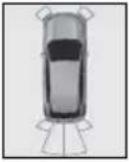 |  |
*: The distance segments will blink rapidly.
■Buzzer operation and distance to an object
A buzzer sounds when the sensors are operating.
● The buzzer beeps faster as the vehicle approaches an object.
When the vehicle comes
within approximately 1.1 ft. (34 cm) of the object, the buzzer sounds continuously.
- When 2 or more sensors simultaneously detect a static object, the buzzer sounds for the nearest object.
- Even when the sensors are
operating, the buzzer will be muted in some situations. (automatic buzzer mute function)
■Muting the buzzer sound
●Automatic buzzer mute function
Even when the sensors are operating, the buzzer will be muted in the following situations:
- The distance between the vehicle and the detected object does not become shorter (except when the distance between the vehicle and object is 1.1 ft. [34 cm] or less).
- Your vehicle is moving away from the object.
• There are no detectable objects entering the path of your vehicle.
However, if another object is detected or the situation changes while the buzzer is muted, the buzzer begins sounding again.
●To mute the buzzer sound
The buzzer can be temporarily
muted by pressing of the meter control switches while a suggestion that says mute is available is shown on the multi-information display.
●When the mute is canceled
Mute will be automatically canceled in the following situations.
- When the shift position is changed
- When the vehicle speed has reached or exceeded a certain speed
- When the Intuitive parking assist is turned off once and turned on again
- When the power switch is turned off once and turned to ON again
Customization
The buzzer volume can be adjusted on the multi-information display. ( P.109)
PKSB (Parking Support Brake)\*
*: If equipped
The Parking Support Brake system consists of the following functions that operate when driving at a low speed or backing up, such as when parking. When the system determines that the possibility of a collision with a detected object is high, a warning operates to urge the driver to take evasive action. If the system determines that the possibility of a collision with a detected object is extremely high, the brakes are automatically applied to help avoid the collision or help reduce the impact of the collision.
PKSB (Parking Support Brake) system
■Parking Support Brake function (static objects)
→P.303
■Parking Support Brake function (rear-crossing vehicles) (if equipped)
→P.309

WARNING
■Limitations of the Parking Support Brake system
Do not overly rely on the system, as doing so may lead to an accident.
Always drive while checking the safety of the surroundings of the vehicle.
Depending on the vehicle and road conditions, weather, etc., the system may not operate.
The detection capabilities of sensors and radars are limited.
Always drive while checking the safety of the surroundings of the vehicle.
●The driver is solely responsible for safe driving. Always drive carefully, taking care to observe your surroundings. The Parking Support Brake system is designed to provide support to lessen the severity of collisions. However, it may not operate in some situations.
●The Parking Support Brake system is not designed to stop the vehicle completely. Additionally, even if the system has stopped the vehicle, it is necessary to depress the brake pedal immediately as brake control will be canceled after approximately 2 seconds.

NOTICE
If “Parking Support Brake Unavailable” is displayed on the multi-information display and the PKSB OFF indicator is flashing
If this message is displayed immediately after the power switch is changed to ON, operate the vehicle carefully, paying attention to your surroundings. It may be necessary to drive the vehicle for a certain amount of time before the system returns to normal. (If the system does not return to normal after driving for a while, clean the sensors and their surrounding area on the bumpers.)
Enabling/Disabling the Parking Support Brake
The Parking Support Brake can
be enabled/disabled on the screen of the multi-information display. All of the Parking Support Brake functions (static objects and rear-crossing vehicles) are enabled/disabled simultaneously. (→P.109)
When the Parking Support Brake is disabled, the PKSB OFF indicator ( P.91) illuminates on the multi-information display.
To re-enable the system, select on the multi-information display, select and turn it on.
If the system is disabled, it will remain off even if the power switch is turned to ON after the power switch has been turned off.

Display and buzzer for hybrid system output restriction control and brake control
If the hybrid system output restriction control or brake control operates, a buzzer will sound and a message will be displayed on the multi-information display, navigation system (if equipped) or multimedia system (if equipped) screen, to alert the driver.
Depending on the situation, hybrid system output restriction control will operate to either limit acceleration or restrict output as much as possible.
● Hybrid system output restriction control is operating (acceleration restriction)
Acceleration greater than a certain amount is restricted by the system.
Navigation system (if equipped) or multimedia system (if equipped) screen: No warning displayed
Multi-information display: "Object Detected Acceleration Reduced"
PKSB OFF indicator: Not illuminated
Buzzer: Does not sound
- Hybrid system output restriction control is operating (output restricted as much as possible)
The system has determined that stronger-than-normal brake operation is necessary.
Navigation system (if equipped) or multimedia system (if equipped) screen: "BRAKE!"
Multi-information display: "BRAKE!"
PKSB OFF indicator: Not illuminated
Buzzer: Short beep
● Brake control is operating
The system determined that emergency braking is necessary.
Navigation system (if equipped) or multimedia system (if equipped) screen: "BRAKE!"
Multi-information display: "BRAKE!"
PKSB OFF indicator: Not illuminated
Buzzer: Short beep
● Vehicle stopped by system operation
The vehicle has been stopped by brake control operation.
Navigation system (if equipped) or multimedia system (if equipped) screen: "Press Brake Pedal"
Multi-information display: "Switch to Brake" (If the accelerator pedal is not depressed, "Brake" will be displayed.)
PKSB OFF indicator: Illuminated
Buzzer: Short beep
System overview
If the Parking Support Brake determines that a collision with a detected object is possible, the hybrid system output will be restricted to restrain any increase in the vehicle speed.
(Hybrid system output restriction control: See figure 2.)
Additionally, if the accelerator pedal continues to be depressed, the brakes will be applied automatically to reduce the vehicle speed. (Brake control: See figure 3.)
● Figure 1: When the PKSB (Parking Support Brake) is not operating
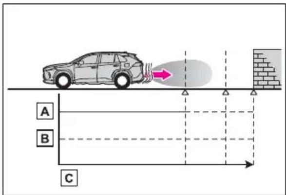
text_image
A B CA Hybrid system output
B Braking force
c Time
● Figure 2: When hybrid system output restriction control operates
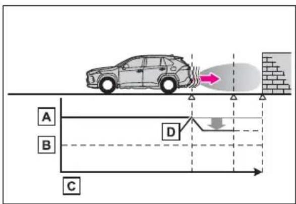
text_image
A B C DA Hybrid system output
B Braking force
c Time
D Hybrid system output restriction control begins operating (System determines that possibility of collision with detected object is high)
● Figure 3: When hybrid system output restriction control and brake control operates
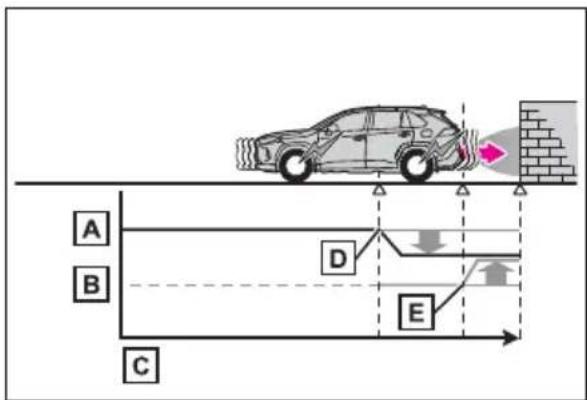
text_image
A B C D EA Hybrid system output
B Braking force
c Time
D Hybrid system output restriction control begins operating (System determines that possibility of collision with detected object is high)
E Brake control begins operating (System determines that possibility of collision with detected object is extremely high)
■If the Parking Support Brake has operated
If the vehicle is stopped due to operation of the Parking Support Brake, the Parking Support Brake will be disabled and the PKSB OFF indicator will illuminate. If the Parking Support Brake operates unnecessarily, brake control can be canceled by
depressing the brake pedal or waiting for approximately 2 seconds for it to automatically be canceled. Then, the vehicle can be operated by depressing the accelerator pedal.
■Re-enabling the Parking Support Brake
To re-enable the Parking Support Brake when it is disabled due to operation of the Parking Support Brake, either enable the system again ( P.299), or turn the power switch to OFF and then back to ON. Additionally, if the object becomes no longer in the traveling direction of the vehicle or if the traveling direction of the vehicle changes (such as changing from moving forward to backing up, or from backing up to moving forward), the system will be re-enabled automatically.
If “Parking Support Brake Unavailable” is displayed on the multi-information display and the PKSB OFF indicator is flashing
- If this message is displayed, a sensor on the front or rear bumper may be dirty. Clean the sensors and their surrounding area on the bumpers.
● Initialization may not have been performed after a 12-volt battery terminal was disconnected and reconnected. Initialize the system. (→P.302) If this message continues to be displayed even after initialization, have the vehicle inspected by your Toyota dealer.
If “Parking Support Brake Unavailable” and “Parking Assist Unavailable Clean Parking Assist Sensor” are displayed on the multi-information display and the PKSB OFF indicator is flashing
●A sensor may be covered with ice, snow, dirt, etc. In this case, remove the ice, snow, dirt, etc., from the sensor to return the sys-
tem to normal. If this message is shown even after removing dirt from the sensor, or shown when the sensor was not dirty to begin with, have the vehicle inspected at your Toyota dealer.
●A sensor may be frozen. Once the ice melts, the system will return to normal.
●Water may be continuously flowing over the sensor surface, such as in a heavy rain. When the system determines that it is normal, the system will return to normal.
If a 12-volt battery terminal has been disconnected and reconnected
The system needs to be initialized. To initialize the system, drive the vehicle straight ahead for 5 seconds or more at a speed of approximately 22 mph (35 km/h) or more.
Parking Support Brake function (static objects) ^*
*: If equipped
If the sensors detect a static object, such as a wall, in the traveling direction of the vehicle and the system determines that a collision may occur due to the vehicle suddenly moving forward due to an accidental accelerator pedal operation, the vehicle moving the unintended direction due to the wrong shift position being selected, or while parking or traveling at low speeds, the system will operate to lessen the impact with the detected static object and reduce the resulting damage.
Examples of function operation
This function will operate in situations such as the following if an object is detected in the traveling direction of the vehicle.
■When traveling at a low speed and the brake pedal is not depressed, or is depressed late

natural_image
Diagram showing a car parking structure before and after change, with no text or symbols present.■When the accelerator pedal is depressed excessively
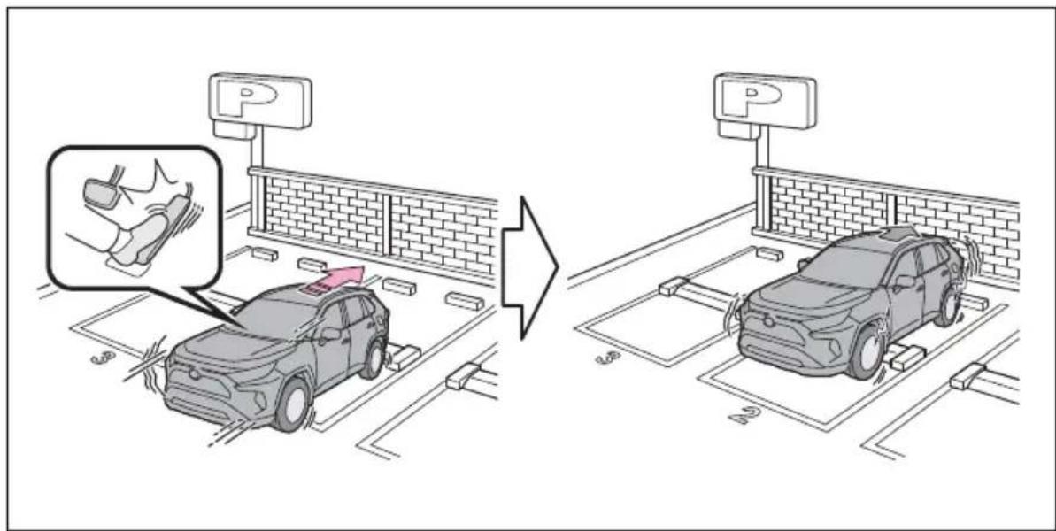
text_image
Diagram illustrating parking fee adjustment on an electric car, showing foot movement and parking fees with a magnified inset of the foot.■When the vehicle moves in the unintended direction due to the wrong shift position being selected
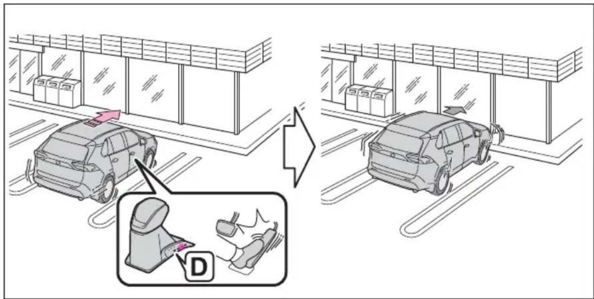
text_image
Diagram illustrating car parking and seatbelt usage, showing two cars with a belt switch and a close-up of the belt switch labeled 'D'.Types of sensors
→P.291

WARNING
■To ensure the Parking Support Brake can operate properly
Observe the following precautions regarding the sensors ( P.291). Failure to do so may cause a sensor to not operate properly, and may cause an accident.
- Do not modify, disassemble or paint the sensors.

WARNING
- Do not replace a sensor with a part other than a genuine part.
- Do not subject a sensor or its surrounding area to a strong impact.
- Do not damage the sensors, and always keep them clean.
- If the area around a radar sensor is subjected to an impact, the system may not operate properly due to a sensor malfunction. Have the vehicle inspected by your Toyota dealer.
■Handling the suspension
Do not modify the suspension, as changes to the height or inclination of the vehicle may prevent the sensors from detecting objects correctly or cause the system to not operate or operate unnecessarily.
■If the Parking Support Brake function (static objects) operates unnecessarily, such as at a railroad crossing
In the event that the Parking Support Brake function (static objects) operates unnecessarily, such as at a railroad crossing, brake control will be canceled after approximately 2 seconds, allowing you to proceed forward and leave the area, brake control can also be canceled by depressing the brake pedal. Depressing the accelerator pedal after brake control is canceled will allow you to proceed forward and leave the area.
■Notes when washing the vehicle
Do not apply intensive bursts of water or steam to the sensor area.
Doing so may result in the sensor malfunctioning.
- When using a high pressure washer to wash the vehicle, do not spray the sensors directly, as doing so may cause a sensor to malfunction.
- When using steam to clean the vehicle, do not direct steam too close to the sensors as doing so may cause a sensor to malfunction.
■When to disable the Parking Support Brake
In the following situations, disable the Parking Support Brake as the system may operate even though there is no possibility of a collision.
- When inspecting the vehicle using a chassis roller, chassis dynamo or free roller
- When loading the vehicle onto a boat, truck or other transport vessel
- If the suspension has been modified or tires of a size other than specified are installed
● If the front of the vehicle is raised or lowered due to the carried load - When equipment that may obstruct a sensor is installed, such as a towing eyelet, bumper protector (an additional trim strip, etc.), bicycle carrier, or snow plow
- When using an automatic car wash
■ The Parking Support Brake function (static object) will operate when
The function will operate when the PKSB OFF indicator is not illuminated or flashing ( P.89, 91) and all of the following conditions are met:
- Hybrid system output restriction control
- The Parking Support Brake is enabled.
- The vehicle speed is 9 mph (15 km/h) or less.
- There is a static object in the traveling direction of the vehicle and 6 to 13 ft. (2 to 4 m) away.
-
The Parking Support Brake determines that a stronger-than-normal brake operation is necessary to avoid a collision.
-
Brake control
- Hybrid system output restriction control is operating
- The Parking Support Brake determines that an immediate brake operation is necessary to avoid a collision.
■ The Parking Support Brake function (static objects) will stop operating when
The function will stop operating if any of the following conditions are met:
- Hybrid system output restriction control
- The Parking Support Brake is disabled.
- The system determines that the collision has become avoidable with normal brake operation.
-
The static object is no longer 6 to 13 ft. (2 to 4 m) away from the vehicle or in the traveling direction of the vehicle.
-
Brake control
- The Parking Support Brake is disabled.
- Approximately 2 seconds have elapsed since the vehicle was
stopped by brake control.
- The brake pedal is depressed after the vehicle is stopped by brake control.
- The static object is no longer 6 to 13 ft. (2 to 4 m) away from the vehicle or in the traveling direction of the vehicle.
■ Detection range of the Parking Support Brake function (static objects)
The detection range of the Parking Support Brake function (static objects) differs from the detection range of the intuitive parking assist. ( P.296) Therefore, even if the intuitive parking assist detects an object and provides a warning, the Parking Support Brake function (static objects) may not start operating.
■ Objects that the Parking Support Brake function (static objects) may not detect
The sensors may not be able to detect certain objects, such as the following:
- Pedestrian
- Cotton, snow, and other materials that are poor reflectors of sonic waves
-
Objects which are not perpendicular to the ground, are not perpendicular to the traveling direction of the vehicle, are uneven or are waving
-
Low objects
- Thin objects such as wires, fences, ropes and signposts
- Objects that are extremely close to the bumper
- Sharply-angled objects
- Tall objects with upper sections projecting outwards in the direction of your vehicle
■ Situations in which the Parking Support Brake function (static objects) may not operate
When the shift lever is in N
■Intuitive parking assist buzzer
Regardless of whether the intuitive parking assist system is enabled or not ( P.293), if the Parking Support Brake function (static objects) is enabled ( P.299), the front or rear sensors detect an object and brake control and hybrid system output restriction control are performed, the intuitive parking assist buzzer will sound to notify the driver of the approximate distance to the object.
■ Situations in which the Parking Support Brake function (static objects) may operate even if there is no possibility of a collision
In some situations, such as the following, the Parking Support Brake function (static objects) may operate even though there is no possibility of a collision.
●Vehicle surroundings
- When driving on a narrow road
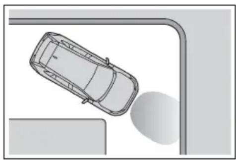
natural_image
Top-down view of a car parked near a road corner with a curved ramp and a vehicle (no text or symbols visible)- When driving on a gravel road or in an area with tall grass
natural_image
Line drawing of a car driving through shallow water with grass and waves (no text or symbols)- When driving toward a banner, flag, low-hanging branch or boom
barrier (such as those used at rail-road crossings, toll gates and parking lots)
- When there is a structure on the roadside (such as when driving in a narrow tunnel, on a narrow bridge or on a narrow road)
- When parallel parking
- When there is a rut or hole in the surface of the road
- When driving on a metal cover (grating), such as those used for drainage ditches
- When driving up or down a steep slope
- If a sensor is hit by a large amount of water, such as when driving on a flooded road
- When loaded on ships or trucks
- Moving type automatic car wash
- Lift type parking area or multi-story parking lot
• Underground parking area
- Structures on the ground (speed bumps, cat's eyes, etc.)
• Differences in height
- When moving straight ahead or turning right
- Snow-melting pipes
• Devices for detecting vehicles, such as traffic lights, devices for detecting traffic congestion, or devices for detecting empty spaces in parking areas
- Railroad tracks
- H-shaped steel
- When there are vehicles on both sides, or there is a vehicle that resembles this vehicle
●Weather
- If a sensor is covered with ice, snow, dirt, etc. (when cleared, the system will return to normal)
- If heavy rain or water strikes a sensor
- When driving in inclement weather such as fog, snow or a sandstorm
• Strong wind is blowing
●Other sonic wave sources
- When vehicle horns, vehicle detectors, motorcycle engines, air brakes of large vehicles, the clearance sonar of other vehicles or
other devices which produce ultrasonic waves are near the vehicle
- If a sticker or an electronic component, such as a backlit license plate (especially fluorescent type), fog lights, fender pole or wireless antenna is installed near a sensor
●Changes in the vehicle posture
- If the vehicle is significantly tilted
- If the front of the vehicle is raised or lowered due to the carried load
- If the orientation of a sensor has been changed due to a collision or other impact
■ Situations in which the Parking Support Brake function (static objects) may not operate properly
In some situations, such as the following, this function may not operate properly.
●Weather
- When a sensor or the area around a sensor is extremely hot or cold
natural_image
Two cartoon illustrations showing a car emitting exhaust smoke from the windshield, with a person cleaning the surface (no text or symbols)- When strong winds are blowing
natural_image
Illustration of a car speeding with falling leaves and smoke, no text or symbols present- If a sensor is covered with ice, snow, dirt, etc. (when cleared, the system will return to normal)
- If heavy rain or water strikes a sensor
- When driving in inclement weather such as fog, snow or a sandstorm
• A sensor is frozen. (Thawing the
area will resolve this problem.)
●Vehicle surroundings
- When an object that cannot be detected is between the vehicle and a detected object
- If an object such as a vehicle, motorcycle, bicycle or pedestrian cuts in front of the vehicle or runs out from the side of the vehicle
- The vehicle is approaching a tall or curved curb.
- On an extremely bumpy road, on an incline, on gravel, or on grass.
- The objects draw too close to the sensor.
●Other sonic waves sources
- When vehicle horns, vehicle detectors, motorcycle engines, air brakes of large vehicles, the clearance sonar of other vehicles or other devices which produce ultrasonic waves are near the vehicle - If a sticker or an electronic component, such as a backlit license plate (especially fluorescent type), fog lights, fender pole or wireless antenna is installed near a sensor
●Changes in the vehicle
- If the vehicle is significantly tilted
- If the front of the vehicle is raised or lowered due to the carried load
- If the orientation of a sensor has been changed due to a collision or other impact
- When equipment that may obstruct a sensor is installed, such as a towing eyelet, bumper protector (an additional trim strip, etc.), bicycle carrier, or snow plow
- If the suspension has been modified or tires of a size other than specified are installed
- If paint or a sticker is applied to the sensor
Parking Support Brake function (rear-crossing vehicles)\*
*: If equipped
If a rear radar sensor detects a vehicle approaching from the right or left at the rear of the vehicle and the system determines that the possibility of a collision is high, this function will perform brake control to reduce the likelihood of an impact with the approaching vehicle.
Examples of function operation
This function will operate in situations such as the following if a vehicle is detected in the traveling direction of the vehicle.
■When reversing, a vehicle is approaching and the brake pedal is not depressed, or is depressed late
natural_image
Illustration of a row of cars with sound waves, no text or symbols presentTypes of sensors
→P.285

WARNING
■To ensure the Parking Support Brake (rear-crossing vehicles) can operate properly
Observe the following precautions regarding the rear radar sensors ( P.285). Failure to do so may cause a sensor to not operate properly, and may cause an accident.

WARNING
- Do not modify, disassemble or paint the sensors.
- Do not replace a rear radar sensor with a part other than a genuine part.
- Do not damage the rear radar sensors, and always keep the radar sensors and their surrounding area on the bumper clean.
- If the area around a rear radar sensor is subjected to an impact, the system may not operate properly due to a sensor malfunction. Have the vehicle inspected by your Toyota dealer.
- Observe the rear radar sensor handling precautions. (→P.285)
■The Parking Support Brake function (rear-crossing vehicles) will operate when
The function will operate when the PKSB OFF indicator is not illuminated or flashing ( P.89, 91) and all of the following conditions are met:
● Hybrid system output restriction control
- The Parking Support Brake is enabled.
- The vehicle speed is 9 mph (15 km/h) or less.
- Vehicles are approaching from the right or left at the rear of the vehicle at a traveling speed of more than approximately 5 mph (8 km/h)
• The shift lever is in R.
- The Parking Support Brake determines that a stronger than normal brake operation is necessary to avoid a collision with an approaching vehicle.
●Brake control
- Hybrid system output restriction control is operating
- The Parking Support Brake determines that an emergency brake operation is necessary to avoid a collision with an approaching vehicle.
■The Parking Support Brake function (rear-crossing vehicles) will stop operating when
The function will stop operating if any of the following conditions are met:
● Hybrid system output restriction control
- The Parking Support Brake is disabled.
- The collision becomes avoidable with normal brake operation.
- A vehicle is no longer approaching from the right or left at the rear of the vehicle.
●Brake control
- The Parking Support Brake is disabled.
- Approximately 2 seconds have elapsed since the vehicle was stopped by brake control.
- The brake pedal is depressed after the vehicle is stopped by brake control.
- A vehicle is no longer approaching from the right or left at the rear of the vehicle.
■ Detection area of the Parking Support Brake function (rear-crossing vehicles)
The detection area of the Parking Support Brake function (rear-crossing vehicles) differs from the detection area of the RCTA function ( P.289). Therefore, even if the RCTA function detects a vehicle and provides an alert, the Parking Support Brake function (rear-crossing vehicles) may not start operating.
■ Conditions under which the Parking Support Brake function (rear-crossing vehicles) will not detect a vehicle
The Parking Support Brake function (rear-crossing vehicles) is not designed to detect the following types of vehicles and/or objects:
● Vehicles approaching from directly behind
● Vehicles backing up in a parking space next to your vehicle
● Vehicles that the sensors cannot detect due to obstructions
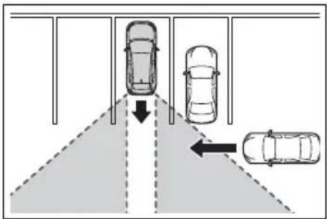
text_image
Diagram showing car parking lane with three cars and directional arrows indicating movement or flow● Vehicles which suddenly accelerate or decelerate near your vehicle
●Guardrails, walls, signs, parked vehicles and similar stationary objects*
● Small motorcycles, bicycles, pedestrians, etc.*
● Vehicles moving away from your vehicle
● Vehicles approaching from the parking spaces next to your vehicle*
- Objects which are extremely close to a radar sensor ^*
● Vehicles which are approaching from the right or left at the rear of the vehicle at a traveling speed of less than approximately 5 mph (8 km/h)
● Vehicles which are approaching from the right or left at the rear of the vehicle at a traveling speed of more than approximately 15 mph (24 km/h)
*: Depending on the conditions, detection of a vehicle and/or object may occur.
■Situations in which the system may operate even though there is no possibility of a collision
In some situations such as the following, the Parking Support Brake function (rear-crossing vehicles) may operate even though there is no possibility of a collision.
- When the parking space faces a street and vehicles are being driven on the street
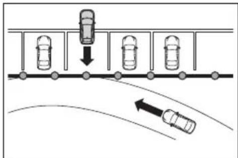
text_image
Diagram showing car parking and road collision with directional arrows indicating movement- When a detected vehicle turns while approaching the vehicle
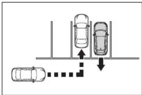
flowchart
graph TD
    A["Top Bus"] --> B["Left Path"]
    B --> C["Right Path"]
    C --> D["Downward Arrow"]
    D --> E["Bottom Route"]
    E --> F["Left Path"]
    style A fill:#f9f,stroke:#333
    style B fill:#ccf,stroke:#333
    style C fill:#cfc,stroke:#333
    style D fill:#fcc,stroke:#333
    style E fill:#ffc,stroke:#333
    style F fill:#cff,stroke:#333
- When a vehicle passes by the side of your vehicle
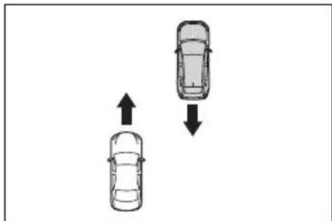
natural_image
Two cars with opposing directional arrows indicating movement or change (no text or symbols)- When the distance between your vehicle and metal objects, such as a guardrail, wall, sign, or parked vehicle, which may reflect electrical waves toward the rear of the
vehicle, is short
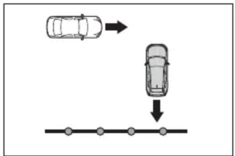
flowchart
graph TD
    A["Top Car"] --> B["Bottom Path"]
    C["Top Car"] --> D["Bottom Path"]
    style A fill:#f9f,stroke:#333
    style B fill:#ccf,stroke:#333
    style C fill:#cfc,stroke:#333
    style D fill:#fcc,stroke:#333
- When there are spinning objects near your vehicle such as the fan of an air conditioning unit
- When water is splashed or sprayed toward the rear bumper, such as from a sprinkler
■ Situations in which the Parking Support Brake function (rear-crossing vehicles) may not operate properly
In some situations, such as the following, the radar sensors may not detect an object and this function may not operate properly
●Stationary objects
- When a sensor or the area around a sensor is extremely hot or cold
- If the rear bumper is covered with ice, snow, dirt, etc.
- When it is raining heavily or water strikes the vehicle
- When the detection area of a radar sensor is obstructed by an adjacent vehicle
●If the vehicle is significantly tilted
- When equipment that may obstruct a sensor is installed, such as a towing eyelet, bumper protector (an additional trim strip, etc.), bicycle carrier, or snow plow
- If the suspension has been modified or tires of a size other than specified are installed
- If the front of the vehicle is raised or lowered due to the carried load
- If a sticker or an electronic component, such as a backlit license plate (especially fluorescent type),
fog lights, fender pole or wireless antenna is installed near a radar sensor
- If the orientation of a radar sensor has been changed
- When multiple vehicles are approaching with only a small gap between each vehicle
- If a vehicle is approaching the rear of your vehicle rapidly
● Situations in which the radar sensor may not detect a vehicle - When a vehicle approaches from the right or left at the rear of the vehicle while you are turning while backing up
- When turning while backing up
natural_image
Top-down diagram of a parking lot with cars and directional arrows indicating movement (no text or symbols)- When backing out of a shallow angle parking spot
flowchart
graph TD
    A["Top Left Car"] --> B["Right Arrow"]
    C["Top Right Car"] --> D["Down Arrow"]
    E["Bottom Right Car"] --> F["Left Arrow"]
- When backing up on a slope with a sharp change in grade
natural_image
Diagram showing two scenarios of cars moving on a road, with arrows indicating direction (no text or symbols)- When a vehicle turns into the detection area
flowchart
graph TD
    A["Top view: four cars in vertical position"] --> B["Downward arrow"]
    B --> C["Left side: two cars in vertical position"]
    D["Right side: one car moving right"]
    E["Bottom view: three cars in vertical position"] --> F["Downward arrow"]
Rear view monitor sys-tem\*
*: If equipped
The rear view monitor sys-tem assists the driver by displaying an image of the view behind the vehicle with fixed guide lines on the screen while backing up, for example while parking.
●The screen illustrations used in this text are intended as examples, and may differ from the image that is actually displayed on the screen.
Driving precautions
The rear view monitor system is a supplemental device intended to assist the driver when backing up. When backing up, be sure to visually check all around the vehicle both directly and using the mirrors before proceeding. If you do not, you may hit another vehicle, and could possibly cause an accident.
Pay attention to the following precautions when using the rear view monitor system.

WARNING
● Never depend on the rear view monitor system entirely when backing up. The image and the position of the guide lines displayed on the screen may differ from the actual state.
Use caution, just as you would when backing up any vehicle.
●Be sure to back up slowly, depressing the brake pedal to control vehicle speed.
●The instructions given are only guide lines. When and how much to turn the steering wheel will vary according to traffic conditions, road surface conditions, vehicle condition, etc. when parking. It is necessary to be fully aware of this before using the rear view monitor system.
- When parking, be sure to check that the parking space will accommodate your vehicle before maneuvering into it.
- Do not use the rear view monitor system in the following cases:
- On icy or slick road surfaces, or in snow
- When using tire chains or emergency tires
- When the back door is not closed completely
- On roads that are not flat or straight, such as curves or slopes
In low temperatures, the screen may darken or the image may become faint. The image could distort when the vehicle is moving, or you may become unable to see the image on the screen. Be sure to visually check all around the vehicle both directly and using the mirrors before proceeding.
- If the tire sizes are changed, the position of the fixed guide lines displayed on the screen may change.
The camera uses a special lens. The distances between objects and pedestrians that appear in the image displayed on the screen will differ from the actual distances. (→P.316)
Screen description
The rear view monitor system screen will be displayed if the shift lever is shifted to the "R" position while the power switch is in ON.
text_image
A A B D CA Vehicle width guide line
Displays a guide path when the vehicle is being backed straight up.
- The displayed width is wider than the actual vehicle width.
B Vehicle center guide line
This line indicates the estimated vehicle center on the ground.
C Distance guide line
Shows distance behind the vehicle.
• Displays a point approximately 1.5 ft. (0.5 m) (red) from the edge of the bumper.
D Distance guide line
Shows distance behind the vehicle.
• Displays a point approximately 3 ft. (1 m) (blue) from the edge of the bumper.
Canceling rear view monitor system
The rear view monitor system is canceled when the shift lever is shifted into any position other than the "R" position.
Rear view monitor system precautions
Area displayed on screen
The rear view monitor system displays an image of the view from the bumper of the rear area of the vehicle.
text_image
Diagram illustrating vehicle detection and parking area layout with labeled components A and a car image showing traffic flow.A Corners of bumper
● The area around both corners of the bumper will not be displayed.
●The image adjustment procedure for the rear view monitor system screen is the same as the procedure for adjusting the screen. (→P.400)
●The area displayed on the screen may vary according to vehicle orientation conditions.
- Objects which are close to either corner of the bumper or under the bumper cannot be displayed.
●The camera uses a special lens. The distance of the image that appears on the screen differs from the actual distance.
●Items which are located higher than the camera may not be displayed on the monitor.
The camera
The camera for the rear view
monitor system is located as shown in the illustration.
natural_image
Technical line drawing of a mechanical component with an inset close-up showing a detail (no text or symbols)■Using the camera
If dirt or foreign matter (such as water droplets, snow, mud, etc.) is adhering to the camera, it cannot transmit a clear image. In this case, flush it with a large quantity of water and wipe the camera lens clean with a soft and wet cloth.

NOTICE
●The rear view monitor system may not operate properly in the following cases.
- If the back of the vehicle is hit, the position and mounting angle of the camera may change.
- As the camera has a water proof construction, do not detach, disassemble or modify it. This may cause incorrect operation.
- When cleaning the camera lens, flush the camera with a large quantity of water and wipe it with a soft and wet cloth. Strongly rubbing the camera lens may cause the camera lens to be scratched and unable to transmit a clear image.
- Do not allow organic solvent, car wax, window cleaner or a glass coating to adhere to the camera. If this happens, wipe it off as soon as possible.
- If the temperature changes rapidly, such as when hot water is poured on the vehicle in cold weather, the system may not operate normally.
- When washing the vehicle, do not apply intensive bursts of water to the camera or camera area. Doing so may result in the camera malfunctioning.
- Do not expose the camera to strong impact as this could cause a malfunction. If this happens, have the vehicle inspected by your Toyota dealer as soon as possible.
Differences between the screen and the actual road
● The distance guide lines and the vehicle width guide lines
may not actually be parallel with the dividing lines of the parking space, even when they appear to be so. Be sure to check visually.
- The distances between the vehicle width guide lines and the left and right dividing lines of the parking space may not be equal, even when they appear to be so. Be sure to check visually.
- The distance guide lines give a distance guide for flat road surfaces. In any of the following situations, there is a margin of error between the guide lines on the screen and the actual distance/course on the road.
■When the ground behind the vehicle slopes up sharply
The distance guide lines will appear to be closer to the vehicle than the actual distance. Because of this, objects will appear to be farther away than they actually are. In the same way, there will be a margin of error between the fixed guide lines and the actual distance/course on the road.
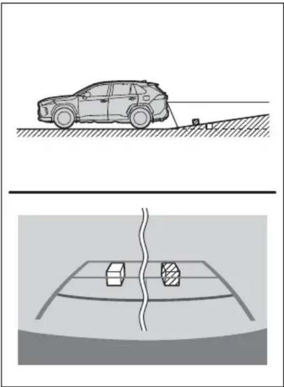
natural_image
Two technical diagrams showing a car on a surface and a vehicle on a road with two boxes, no text or symbols present.■When the ground behind the vehicle slopes down sharply
The distance guide lines will appear to be farther from the vehicle than the actual distance. Because of this, objects will appear to be closer than they actually are. In the same way, there will be a margin of error between the guide lines and the actual distance/course on the road.
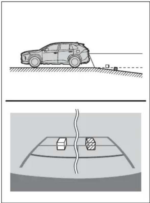
natural_image
Diagram showing a car on a road with a sensor and a vehicle detection area below (no text or symbols)■When any part of the vehicle sags
When any part of the vehicle sags due to the number of passengers or the distribution of the load, there is a margin of error between the fixed guide lines on the screen and the actual distance/course on the road.
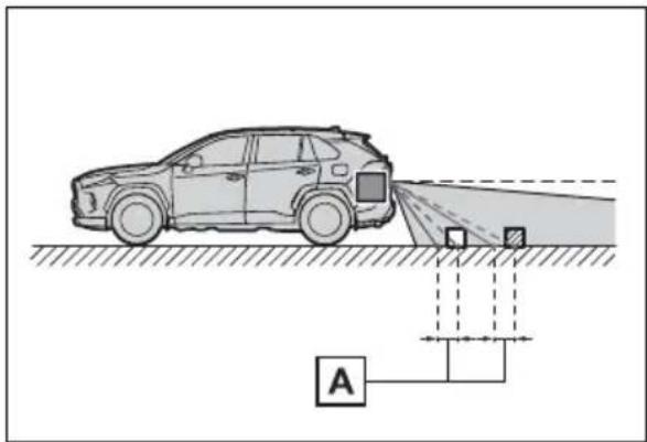
text_image
Diagram showing a car approaching a road with a sensor or detection system labeled 'A' connected to a ground reference point.A margin of error
When approaching three-dimensional objects
The distance guide lines are displayed according to flat surfaced objects (such as the road). It is not possible to determine the position of three-dimensional objects (such as vehicles) using the vehicle width guide lines and distance guide lines. When approaching a three-dimensional object that extends outward (such as the flatbed of a truck), be careful of the following.
■Vehicle width guide lines
Visually check the surroundings and the area behind the vehicle. In the case shown below, the truck appears to be outside of the vehicle width guide lines and the vehicle does not look as if it hits the truck. However, the rear body of the truck may actually cross over the vehicle width guide lines. In reality if you back up as guided by the vehicle width guide lines, the vehicle may hit the truck.
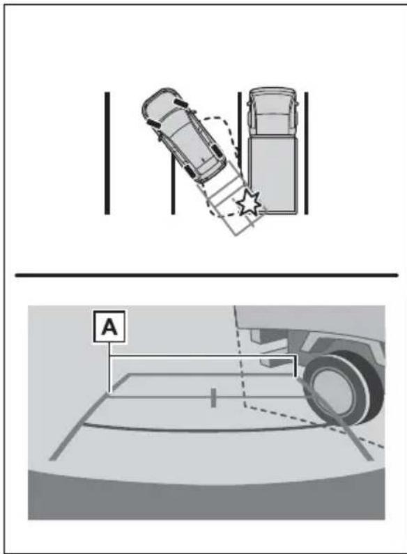
text_image
Diagram showing a car climbing stairs with a star and a parking lot marked 'A', alongside a vehicle diagram.A Vehicle width guide lines
■Distance guide lines
Visually check the surroundings and the area behind the vehicle. On the screen, it appears that a truck is parking at point B However, in reality if you back
up to point A you will hit the truck. On the screen, it appears that A is closest and is farthest away. However, in reality, the distance to A and is the same, and B is farther than A and C
text_image
A B CThings you should know
If you notice any symptoms
If you notice any of the following symptoms, refer to the likely cause and the solution, and re-check.
If the symptom is not resolved by the solution, have the vehicle inspected by your Toyota dealer.
| Symptom Likely cause Solution | ||
| The image is difficult to see | The vehicle is in a dark areaThe temperature around the lens is either high or lowThe outside temperature is lowThere are water droplets on the cameraIt is raining or humidForeign matter (mud etc.) is adhering to the cameraSunlight or headlights are shining directly into the cameraThe vehicle is under fluorescent lights, sodium lights, mercury lights etc. | Back up while visually checking the vehicle's surroundings. (Use the monitor again once conditions have been improved.)The procedure for adjusting the picture quality of the rear view monitor system is the same as the procedure for adjusting the screen. (→P.400) |
| The image is blurry | Dirt or foreign matter (such as water droplets, snow, mud etc.) is adhering to the camera. | Flush the camera with a large quantity of water and wipe the camera lens clean with a soft and wet cloth. |
| The image is out of alignment | The camera or surrounding area has received a strong impact. | Have the vehicle inspected by your Toyota dealer. |
| The fixed guide lines are very far out of alignment | The camera position is out of alignment. | Have the vehicle inspected by your Toyota dealer. |
| The vehicle is tilted (there is a heavy load on the vehicle, tire pressure is low due to a tire puncture, etc.)The vehicle is used on an incline. | If this happens due to these causes, it does not indicate a malfunction.Back up while visually checking the vehicle's surroundings. | |
Toyota parking assist monitor\*
*: If equipped
The parking assist monitor assists the driver by displaying an image of the view behind the vehicle while backing up, for example while parking.
When the display is changed to the wide rear view mode, a wider lateral view behind the vehicle will be displayed.
●The screen illustrations used in this text are intended as examples, and may differ from the image that is actually displayed on the screen.
Driving precautions
The parking assist monitor is a supplemental device intended to assist the driver when backing up. When backing up, be sure to visually check all around the vehicle both directly and using the mirrors before proceeding. If you do not, you may hit another vehicle, and could possibly cause an accident.
Pay attention to the following precautions when using the parking assist monitor.

WARNING
●Never depend on the parking assist monitor entirely when backing up. The image and the position of the guide lines displayed on the screen may differ from the actual state.
Use caution, just as you would when backing up any vehicle.
● Be sure to back up slowly, depressing the brake pedal to control vehicle speed.
- If you seem likely to hit nearby vehicles, obstacles, people or mount the shoulder, depress the brake pedal to stop the vehicle.
●The instructions given are only guidelines. When and how much to turn the steering wheel will vary according to traffic conditions, road surface conditions, vehicle condition, etc. when parking. It is necessary to be fully aware of this before using the parking assist system.
- When parking, be sure to check that the parking space will accommodate your vehicle before maneuvering into it.
- Do not use the parking assist monitor in the following cases:
- On icy or slick road surfaces, or in snow
- When using tire chains or emergency tires
- When the back door is not closed completely
- On roads that are not flat or straight, such as curves or slopes
- If the suspension has been modified or tires of a size other than specified are installed

WARNING
In low temperatures, the screen may darken or the image may become faint. The image could distort when the vehicle is moving, or you may become unable to see the image on the screen. Be sure to visually check all around the vehicle both directly and using the mirrors before proceeding.
- If the tire sizes are changed, the position of the guide lines displayed on the screen may change.
The camera uses a special lens. The distances between objects and pedestrians that appear in the image displayed on the screen will differ from the actual distances. (→P.328)
Screen display
The parking assist monitor screen will be displayed if the shift lever is shifted to the "R" while the power switch is in ON.
Each time the display mode switching button is selected, the mode will change as follows:
▶ Rear view
Displays the rear view of the vehicle.
text_image
C D A BA Display mode switching button
Each time the button is selected, the rear view mode and the wide rear view mode are switched.
B Guide line switching button
Select to switch the guide line mode. (→P.323)
• Each time the button is selected, the display mode changes in the following order:
Estimated course line display mode → Parking assist guide line display mode → Distance guide line display mode.
C Rear Cross Traffic Alert*
When a sensor detects a vehicle approaching from the rear, the direction of the vehicle approaching from the rear is displayed and the buzzer sounds.
D Intuitive parking assist*
When a sensor detects a stationary object, the direction of and the approximate distance to the a stationary object are displayed and the buzzer sounds.
*: If equipped
▶ Wide rear view
Displays a near 180^ image from the rear view camera.
text_image
C D A BA Display mode switching button
Each time the button is selected, the rear view mode and the wide rear view mode are switched.
B Guide line switching button
Select to switch the guide line mode. (→P.323)
• Each time the button is selected, the display mode changes in the following order:
Estimated course line display mode → Parking assist guide line display mode → Distance guide line display mode.
C Rear Cross Traffic Alert*
When a sensor detects a stationary object, the direction of stationary object is displayed and the buzzer sounds.
D Intuitive parking assist*
When a sensor detects an obstacle, the direction of and the approximate distance to the obstacle are displayed and the buzzer sounds.
*: If equipped
For details about the Rear Cross Traffic Alert function ( P.288) and intuitive parking assist. ( P.291)

WARNING
As the Rear Cross Traffic Alert display is displayed over the camera view, it may be difficult to see the Rear Cross Traffic Alert display depending on the color and brightness of the surrounding area.
Canceling Toyota parking assist monitor
The parking assist monitor is canceled when the shift lever is shifted into any position other than the "R".
Using the system
Use any of the following modes.
text_image
Diagram showing a car dropping from top to bottom with a pink arrow indicating direction, alongside three cars below each.▶ Estimated course line display mode ( P.324)
Estimated course lines are displayed which move in accordance with the operation of the steering wheel.
natural_image
Simple line drawing of a car wheel with no text or symbolsParking assist guide line display mode ( P.325)
The steering wheel return points (parking assist guide lines) are displayed.
This mode is recommended for
those who are comfortable with parking the vehicle without the aid of the estimated course lines.
natural_image
Simple line drawing of a dome-shaped structure with curved lines and a small icon below (no text or symbols)▶ Distance guide line display mode ( P.326)
Distance guide lines only are displayed.
This mode is recommended for those who are comfortable with parking the vehicle without the aid of the guide lines.

natural_image
Simple line drawing of a curved shape with two curved ends, no text or symbols presentEstimated course line display mode
Screen description
▶ Rear view
flowchart
graph TD
    A["A"] --> C["C"]
    B["B"] --> C["C"]
    C["C"] --> D["D"]
    E["E"] --> C["C"]
    style A fill:#f9f,stroke:#333
    style B fill:#f9f,stroke:#333
    style C fill:#f9f,stroke:#333
    style D fill:#f9f,stroke:#333
    style E fill:#f9f,stroke:#333
A Vehicle width guide line
Displays a guide path when the vehicle is being backed straight up.
B Estimated course lines
Show an estimated course when the steering wheel is turned.
C Distance guide lines
Show distance behind the vehicle when the steering wheel is turned.
- The guide lines move in conjunction with the estimated course lines.
- The guide lines display points approximately 1.5 ft. (0.5 m) (red) and approximately 3 ft. (1 m) (yellow) from the center of the edge of the bumper.
D Distance guide line Shows distance behind the vehicle.
• Displays a point approximately 1.5 ft. (0.5 m) (blue) from the edge of the bumper.
E Vehicle center guide line Indicates the estimated vehicle center on the ground.
▶ Wide rear view
text_image
A B C E DA Vehicle width guide line
Displays a guide path when the vehicle is being backed straight up.
B Estimated course lines
Show an estimated course when the steering wheel is turned.
C Distance guide lines
Show distance behind the vehicle when the steering wheel is turned.
- The guide lines move in conjunction with the estimated course lines.
- The guide lines display points approximately 1.5 ft. (0.5 m) (red) and approximately 3 ft. (1 m) (yellow) from the center of the edge of the bumper.
D Distance guide line
Shows distance behind the vehicle.
• Displays a point approximately 1.5 ft. (0.5 m) (blue) from the edge of the bumper.
E Vehicle center guide line
Indicates the estimated vehicle center on the ground.

WARNING
- If the steering wheel is straight and the vehicle width guide lines and the estimated course lines are not in alignment, have the vehicle inspected by your Toyota dealer.
Parking assist guide line display mode
Screen description
▶ Rear view
text_image
A B C DA Vehicle width guide line
Displays a guide path when the vehicle is being backed straight up.
- The displayed width is wider than the actual vehicle width.
B Parking assist guide lines
Show the path of the smallest turn possible behind the vehicle.
C Distance guide line
Shows distance behind the vehicle.
- Displays points approximately 1.5 ft. (0.5 m) (red) from the edge of the bumper.
D Vehicle center guide line
Indicates the estimated vehicle center on the ground.
▶ Wide rear view
text_image
A B D CA Vehicle width guide line
Displays a guide path when the vehicle is being backed straight up.
- The displayed width is wider than the actual vehicle width.
B Parking assist guide lines
Show the path of the smallest turn possible behind the vehicle.
C Distance guide line
Shows distance behind the vehicle.
• Displays points approximately 1.5 ft. (0.5 m) (red) from the edge of the bumper.
D Vehicle center guide line
Indicates the estimated vehicle center on the ground.
Distance guide line dis- play mode
Screen description
▶ Rear view
natural_image
Simple diagram showing a curved line with a labeled point 'A' and two small icons below (no text or symbols on the main diagram)A Distance guide lines
Shows distance behind the vehicle.
• Displays points approximately 1.5 ft. (0.5 m) (red) from the edge of the bumper.
Wide rear view
natural_image
Simple diagram showing a curved line inside a rectangular frame with labeled point A and icons at bottom (no text or symbols on the diagram itself)A Distance guide lines
Shows distance behind the vehicle.
• Displays points approximately 1.5 ft. (0.5 m) (red) from the edge of the bumper.
Toyota parking assist monitor precautions
Area displayed on screen
The parking assist monitor displays an image of the view from the bumper of the rear area of the vehicle.
▶ Rear view
text_image
Diagram illustrating car safety scenarios with labeled components and safety symbolsA Corners of bumper
• The area around both corners of the bumper will not be displayed.
▶ Wide rear view
text_image
Diagram illustrating vehicle parking and parking layout with labeled components and directional arrowsA Corners of bumper
• The area around both corners of the bumper will not be displayed.
●The image adjustment procedure for the parking assist monitor screen is the same as the procedure for adjusting the screen display. (→P.400)
●The area displayed on the screen may vary according to vehicle orientation conditions.
- Objects which are close to either corner of the bumper or under the bumper cannot be displayed.
●The camera uses a special lens. The distance of the image that appears on the screen differs from the actual distance.
●Items which are located higher than the camera may not be displayed on the monitor.
The camera
The camera for the parking assist monitor is located as shown in the illustration.
natural_image
Technical line drawing of a mechanical component with an inset close-up showing a detail (no text or symbols)■Using the camera
If dirt or foreign matter (such as water droplets, snow, mud, etc.) is adhering to the camera, it cannot transmit a clear image. In this case, flush it with a large quantity of water and wipe the camera lens clean with a soft and wet cloth.

NOTICE
●The parking assist monitor may not operate properly in the following cases.
- If the back of the vehicle is hit, the position and mounting angle of the camera may change.
- As the camera has a water proof construction, do not detach, disassemble or modify it. This may cause incorrect operation.
- When cleaning the camera lens, flush the camera with a large quantity of water and wipe it with a soft and wet cloth. Strongly rubbing the camera lens may cause the camera lens to be scratched and unable to transmit a clear image.
- Do not allow organic solvent, car wax, window cleaner or a glass coating to adhere to the camera. If this happens, wipe it off as soon as possible.
- If the temperature changes rapidly, such as when hot water is poured on the vehicle in cold weather, the system may not operate normally.
- When washing the vehicle, do not apply intensive bursts of water to the camera or camera area. Doing so may result in the camera malfunctioning.
- Do not expose the camera to strong impact as this could cause a malfunction. If this happens, have the vehicle inspected by your Toyota dealer as soon as possible.
Differences between the screen and the actual road
● The distance guide lines and the vehicle width guide lines
may not actually be parallel with the dividing lines of the parking space, even when they appear to be so. Be sure to check visually.
- The distances between the vehicle width guide lines and the left and right dividing lines of the parking space may not be equal, even when they appear to be so. Be sure to check visually.
- The distance guide lines give a distance guide for flat road surfaces. In any of the following situations, there is a margin of error between the guide lines on the screen and the actual distance/course on the road.
■When the ground behind the vehicle slopes up sharply
The distance guide lines will appear to be closer to the vehicle than the actual distance. Because of this, objects will appear to be farther away than they actually are. In the same way, there will be a margin of error between the guidelines and the actual distance/course on the road.
natural_image
Two technical diagrams showing a car on a slope and its corresponding parking lot view with two boxes, no text or symbols present.■When the ground behind the vehicle slopes down sharply
The distance guide lines will appear to be farther from the vehicle than the actual distance. Because of this, objects will appear to be closer than they actually are. In the same way, there will be a margin of error between the guidelines and the actual distance/course on the road.
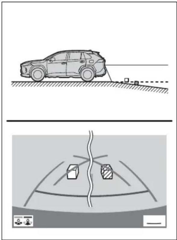
natural_image
Diagram showing a car on a road with a sensor and a vehicle detection scenario below (no text or symbols)■When any part of the vehicle sags
When any part of the vehicle sags due to the number of passengers or the distribution of the load, there is a margin of error between the guide lines on the screen and the actual distance/course on the road.
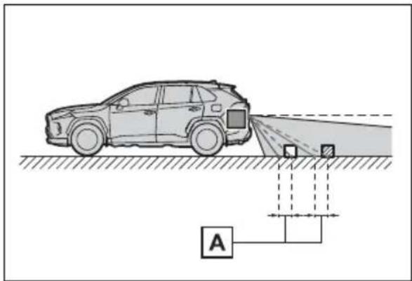
text_image
Diagram showing a car approaching a road with a sensor and labeled point A, likely illustrating a surveillance or tracking system.A margin of error
When approaching three-dimensional objects
The estimated course lines target flat surfaced objects (such as the road). It is not possible to determine the position of three-dimensional objects (such as vehicles) using the estimated course lines and distance guide lines. When approaching a three-dimensional object that extends outward (such as the flatbed of a truck), be careful of the following.
■Estimated course lines
Visually check the surroundings and the area behind the vehicle. In the case shown below, the truck appears to be outside of the estimated course lines and the vehicle does not look as if it hits the truck. However, the rear body of the truck may actually cross over the estimated course lines. In reality if you back up as guided by the estimated course lines, the vehicle may hit the truck.
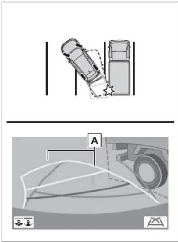
text_image
Diagram showing a car collision scenario with a star symbol and a vehicle detection area labeled 'A'A Estimated course lines
■Distance guide lines
Visually check the surroundings and the area behind the vehicle. On the screen, it appears that a truck is parking at point B However, in reality if you back
up to point A you will hit the truck. On the screen, it appears that A is closest and is farthest away. However, in reality, the distance to A and is the same, and B is farther than A and C
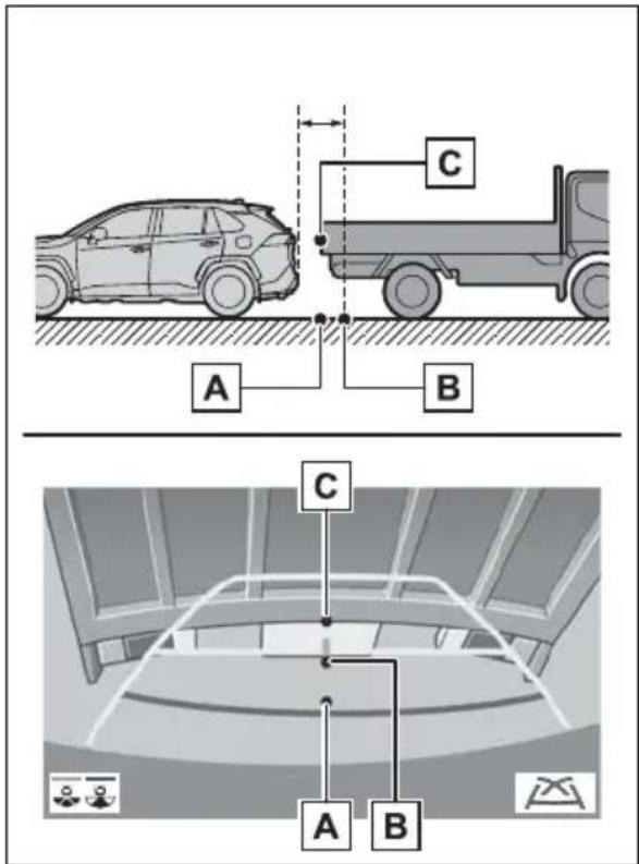
text_image
A B C C A BThings you should know
If you notice any symptoms
If you notice any of the following symptoms, refer to the likely cause and the solution, and re-check.
If the symptom is not resolved by the solution, have the vehicle inspected by your Toyota dealer.
| Symptom Likely cause Solution | ||
| The image is difficult to see | The vehicle is in a dark areaThe temperature around the lens is either high or lowThe outside temperature is lowThere are water droplets on the cameraIt is raining or humidForeign matter (mud etc.) is adhering to the cameraSunlight or headlights are shining directly into the cameraThe vehicle is under fluorescent lights, sodium lights, mercury lights etc. | Back up while visually checking the vehicle's surroundings. (Use the monitor again once conditions have been improved.)The procedure for adjusting the picture quality of the parking assist monitor is the same as the procedure for adjusting the screen display. ( P.400) |
| The image is blurry | Dirt or foreign matter (such as water droplets, snow, mud etc.) is adhering to the camera. | Flush the camera with a large quantity of water and wipe the camera lens clean with a soft and wet cloth. |
| The image is out of alignment | The camera or surrounding area has received a strong impact. | Have the vehicle inspected by your Toyota dealer. |
| The guide lines are very far out of alignment | The camera position is out of alignment. | Have the vehicle inspected by your Toyota dealer. |
| The vehicle is tilted (there is a heavy load on the vehicle, tire pressure is low due to a tire puncture, etc.)The vehicle is used on an incline. | If this happens due to these causes, it does not indicate a malfunction.Back up while visually checking the vehicle's surroundings. | |
| The estimated course lines move even though the steering wheel is straight | There is a malfunction in the signals being output by the steering sensor. | Have the vehicle inspected by your Toyota dealer. |
| Guide lines are not displayed | The back door is open. | Close the back door.If this does not resolve the symptom, have the vehicle inspected by your Toyota dealer. |
| The estimated course lines are not displayed | 12-volt battery has been reinstalled.The steering wheel has been moved while the 12-volt battery was being reinstalled.12-volt battery power is low.The steering sensor has been reinstalled.There is a malfunction in the signals being output by the steering sensor. | Stop the vehicle, and turn the steering wheel as far as it will go to the left and right.If this does not resolve the symptom, have the vehicle inspected by your Toyota dealer. |
Panoramic view monitor\*
*: If equipped
Panoramic view monitor assists the driver in viewing the surroundings, when operating at low speeds, by combining the front, side and rear cameras and displaying a complete vehicle overhead image on the screen.
When you press the camera switch or shift the shift lever to the "R" position while the power switch is in ON, the panoramic view monitor operates.
The monitor displays various views of the position and surroundings of the vehicle.
●The screen illustrations used in this text are intended as examples, and may differ from the image that is actually displayed on the screen.
Driving precautions
The panoramic view monitor is a supplemental device intended to assist the driver when checking around the vehicle. When using, be sure to visually check all around the vehicle both directly and using the mirrors before proceeding. If you do not, you
may hit another vehicle or possibly cause an accident.
Pay attention to the following precautions when using the panoramic view monitor.

WARNING
●Never depend on the panoramic view monitor entirely. The image and the position of the guide lines displayed on the screen may differ from the actual state. Use caution just as you would when driving any other vehicle.
●Always make sure to check all around the vehicle with your own eyes when driving.
- Never drive while looking only at the screen as the image on the screen is different from actual conditions. If you are driving while looking only at the screen, you may hit a person or an object, resulting in an accident. When driving, be sure to check the vehicle's surroundings with your own eyes and the vehicle's mirrors.
● Depending on the circumstances of the vehicle (number of passengers, amount of luggage, etc.), the position of the guide lines displayed on the screen may change. Be sure to check visually around the vehicle before proceeding.

WARNING
- Do not use the panoramic view monitor system in the following cases:
- On icy or slick road surfaces, or in snow
- When using tire chains or emergency tires
- When the front door or the back door is not closed completely
- On roads that are not flat or straight, such as curves or slopes
- If the suspension has been modified or tires of a size other than specified are installed
In low temperatures, the screen may darken or the image may become faint. The image could distort when the vehicle is moving, or you may become unable to see the image on the screen. Be sure to visually check all around the vehicle both directly and using the mirrors before proceeding. - If the tire sizes are changed, the position of the guide lines displayed on the screen may change.
The camera uses a special lens. The distances between objects and pedestrians that appear in the image displayed on the screen will differ from the actual distances. (→P.358) - When an aftermarket part is installed in the display area of the screen.

NOTICE
In panoramic view/moving view/see-through view, the system combines images taken from the front, back, left and right side cameras into a single image. There are limits to the range and content that can be displayed. Familiarize yourself with the characteristics of the panoramic view monitor system before using it.
● Image clarity may decline at the four corners of the panoramic view/moving view/see-through view. However, this is not a malfunction, as these are the regions along the border of each camera image where the images are combined.
● Depending on lighting conditions near each of the cameras, bright and dark patches may appear on the panoramic view/moving view/see-through view.
●The panoramic view/moving view/see-through view display does not extend higher than the installation position and image capture range of each camera.
There are blind spots around the vehicle. Accordingly, there are regions not displayed in panoramic view.
● Three-dimensional objects displayed in wide front view, rear view, wide rear view or side view may not be displayed in panoramic view/moving view/see-through view.

NOTICE
●People and other three-dimensional obstacles may appear differently when displayed on the panoramic view monitor. (These differences include, among others, cases in which displayed objects appear to have fallen over, disappear near image processing areas, appear from image processing areas, or when the actual distance to an object differs from the displayed position.)
- When the back door, which is equipped with the back camera, or front doors, which are equipped with door mirrors that have built-in side cameras, are open, images will not be displayed properly on the panoramic view monitor.
The vehicle icon displayed in panoramic view/moving view/see-through view is a computer generated image. Accordingly, properties such as the color, shape and size will differ from the actual vehicle. For this reason, nearby three-dimensional objects may appear to be touching the vehicle, and actual distances to three-dimensional objects may differ from those displayed.
Camera switch
The camera switch is located as shown in the illustration.
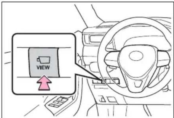
text_image
VIEWDisplay
Checking around the vehicle
▶ Moving view
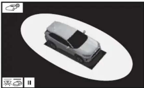
natural_image
Top-down view of a car on a roof with an oval background (no text or symbols visible)▶ See-through view
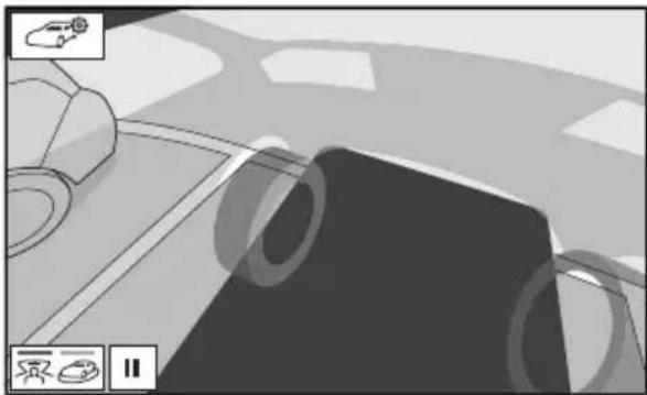
natural_image
Top-down view of a car interior with visible steering wheel and dashboard (no text or symbols)Checking the front and around the vehicle
▶ Wide front view & panoramic view
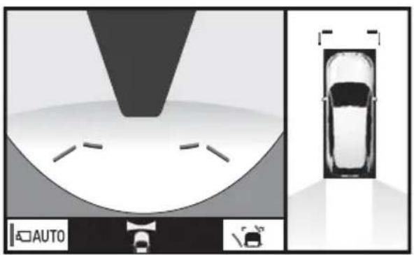
natural_image
Top-down view of a car with a roof-mounted sensor array and a car silhouette (no text or symbols visible)When folding the outside rear view mirrors
▶ Wide front view & side views
natural_image
Diagram of a mechanical assembly or assembly with no visible text, numbers, or symbols.Side views
Checking the rear and around the vehicle
▶ Rear view & panoramic view
natural_image
Diagram showing a structural frame and a car with exhaust hood, alongside a toolbar with icons (no text or symbols on main elements)
natural_image
3D rendering of a mechanical component with symmetric triangular shapes and a central shaft (no text or symbols)▶ Rear view & side views
natural_image
Architectural diagram of a triangular roof structure with support symbols (no text or labels)How to switch the display
When you press the camera switch or shift the shift lever to the "R" position while the power switch is in ON, the panoramic view monitor operates.
The monitor displays various views of the position of the vehicle. (The following is an example)
When the shift lever is in the "P" position
A
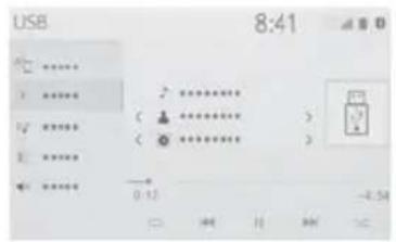
text_image
USB 8:41 ↑ ↓ ↑ ↓ ← 0:12 -4.54
B
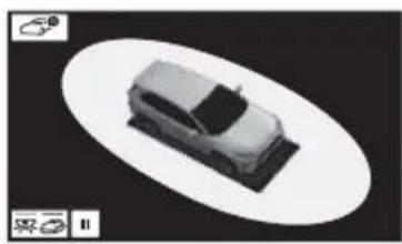
natural_image
3D rendering of a car on a flat surface with an oval frame, no visible text or symbols
C
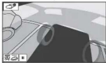
natural_image
Interior view of a car with visible steering wheel and dashboard (no text or symbols)A Audio screen, etc.
B Moving view
C See-through view
When the shift lever is in the "D" or "N" position
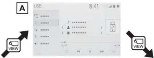
text_image
USB 8:41 VIEW VIEWC
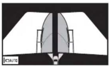
natural_image
Technical diagram of a mechanical component with symmetrical sections and a central vertical axis (no text or symbols)
B
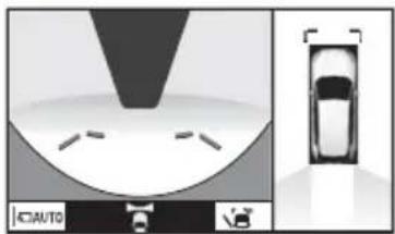
natural_image
Top-down view of a car undercarriage with a car silhouette and license plate (no text or symbols)A Audio screen, etc.
B Wide front view & panoramic view
c Side views
When the shift lever is in the "R" position
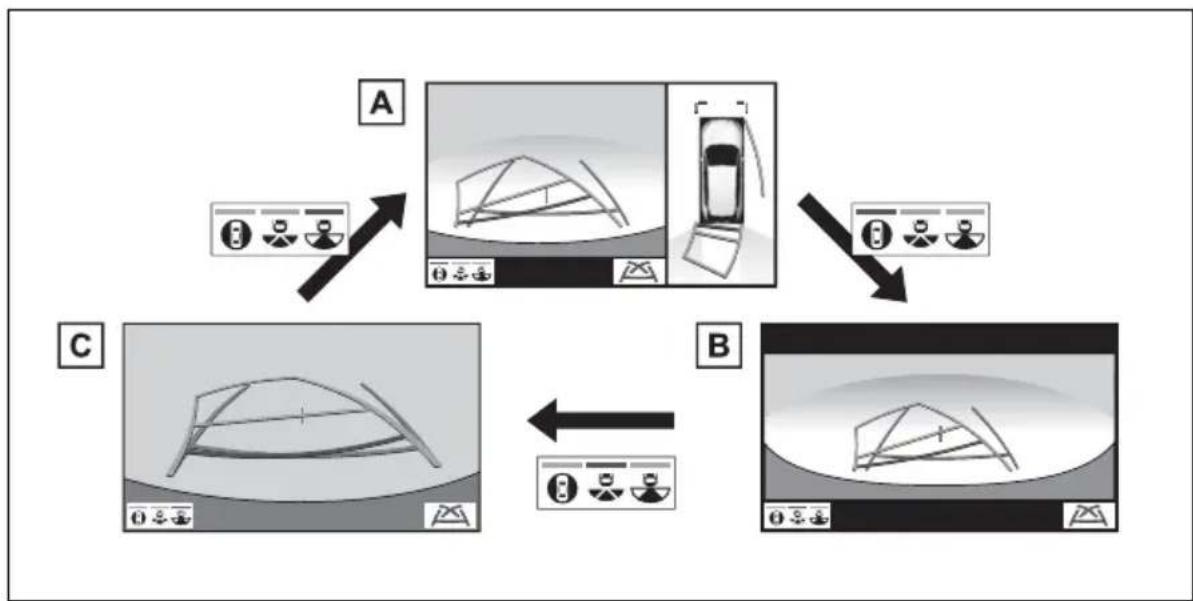
flowchart
graph TD
    A["Step A: Car Icon with directional arrows"] --> B["Step B: Bridge Diagram with icons"]
    B --> C["Step C: Bridge Diagram with icons"]
    C --> A
A Rear view & panoramic view
B Wide rear view
C Rear view
Checking around the vehicle
The moving view screen and the see-through view screen provide support when checking the areas of around the vehicle while parking. These screens display an image of the vicinity of the vehicle combined from the 4 cameras. The screen will display a 360° view around the vehicle from either inside the vehicle or from a birds-eye view at an angle.
To display the moving view/see-through view screen, press the camera switch when the shift lever is in the "P" position and the intuitive parking assist is enabled.
Screen display
▶ Moving view
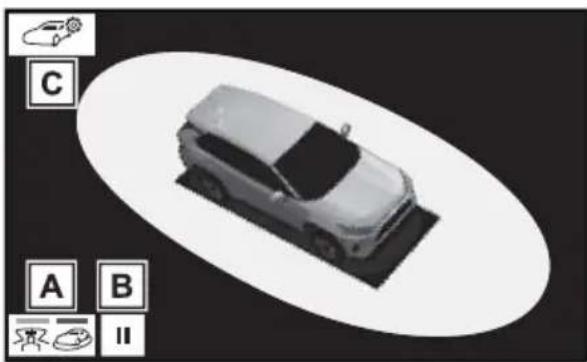
natural_image
3D rendering of a car on a roof with three labeled icons (A, B, C) in the corner, no text or symbols on the car itself.A Display mode switching button
Select to change the display mode between the moving view and the see-through view.
B Rotation pause switch
Select to pause the rotation of the
screen.
To resume rotation, select

C Body color setting switch
Select to display the body color setting screen and change the color of the vehicle displayed on the panoramic view monitor. (→P.353)
▶ See-through view
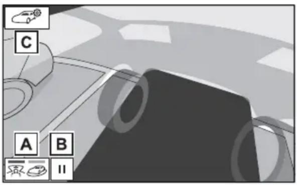
text_image
C A B IIA Display mode switching but-
ton
Select to change the display mode between the moving view and the see-through view.
B Rotation pause switch
Select to pause the rotation of the screen.
To resume rotation, select

C Body color setting switch
Select to display the body color setting screen and change the color of the vehicle displayed on the panoramic view monitor. (→P.353)
- Pressing the camera switch again changes the screen back to the previously displayed screen, such as the audio screen.
Checking the front and around the vehicle
The wide front view & panoramic view screen provides support when checking the areas in front of the vehicle and around the vehicle when taking-off at T-intersections or other intersections during poor visibility.
To display the screen, press the camera switch when the shift lever is in the “N” or “D” position with the vehicle moving approximately 7 mph (12 km/h) or less.
This screen will be displayed if the intuitive parking assist detects an object in front of your vehicle (intuitive parking assist linked display).
Screen display
▶ Wide front view & panoramic view
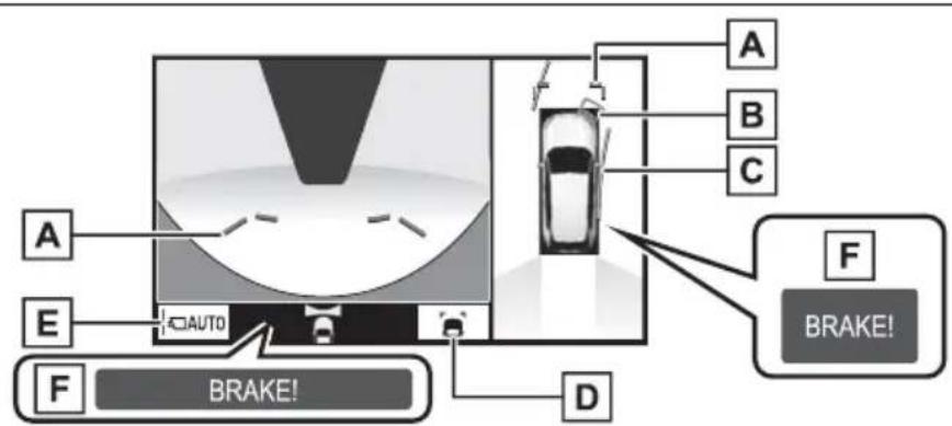
text_image
A B C E AUTO F BRAKE! D F BRAKE!A Distance guide lines
Shows distance in front of the vehicle.
• Display points approximately 3 ft. (1 m) from the edge of the bumper.
B Intuitive parking assist
When a sensor detects an obstacle, the direction of and the approximate distance to the obstacle are displayed and the buzzer sounds.
C Estimated course lines
Shows an estimated course when the steering wheel is turned.
- This line will be displayed when the steering wheel is turned by 90^ or more from the center (straight-line) position.
D Guide line switching button
Select to change the guide line mode between the distance guide line mode and the estimated course line mode. ( P.342)
E Automatic display button
Select to turn automatic display mode on/off. The indicator on the button illuminates during automatic display mode. (→P.342)
F Parking Support Brake*
When the system determines that the possibility of a frontal collision with a detected object is high, a warning message is displayed.
*: If equipped
- Pressing the camera switch changes the screen to the side views screen or previously displayed screen, such as the audio screen.
- For details about the intuitive parking assist (→P.291) and Parking Support Brake* function. (→P.298)
● The display position of the intuitive parking assist and the position of obstacles displayed in the camera image do not match.
*: If equipped

WARNING
- When a sensor indicator on the intuitive parking assist display illuminates in red or a buzzer sounds continuously, be sure to check the area around the vehicle immediately and do not proceed any further until safety has been ensured, otherwise an unexpected accident may occur.
As the intuitive parking assist display is displayed over the camera view, it may be difficult to see the intuitive parking assist display depending on the color and brightness of the surrounding area.
Switching the guide line mode
Each time the guide line switching button is selected, the mode will change as follows:
▶ Distance guide line

natural_image
Top-down diagram of a car interior with a car silhouette and directional indicators (no text or symbols)- Only the distance guide lines are displayed.
▶ Estimated course line
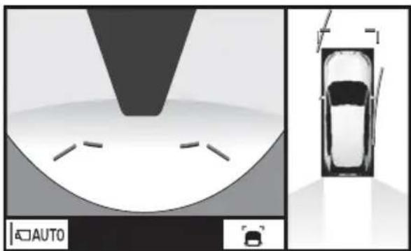
natural_image
Top-down view of a car with a parking sign and a side-view diagram showing the front and rear views (no text or symbols)● Estimated course lines will be added to the distance guide lines.
Automatic display mode
In addition to screen switching by operating the camera switch, automatic display mode is available. In this mode, the screen is switched automatically in response to vehicle speed.
In automatic display mode, the monitor will automatically display images in the following situations:
- When the shift lever is shifted to "N" or "D" position.
- When vehicle speed is reduced to approximately 6 mph (10 km/h) or less.
Checking the sides of the vehicle
The side view screen displays images from the cameras installed on
each outside rear view mirror. This screen is designed to support the driver in safe driving in situations such as when driving on a narrow road, by allowing them to check the areas around the sides of the vehicle.
To display the screen, press the camera switch when the shift lever is in the “D”, or “N” position with the vehicle moving approximately 7 mph (12 km/h) or less.
Screen display
▶ Side view
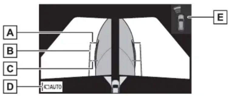
text_image
A B C D AUTO EA Distance guide lines
Show distance in front of the vehicle.
- Display points approximately 3 ft. (1 m) from the edge of the bumper.
B Vehicle width guide lines
Shows guide lines of the vehicle's width including the outside rear view mirrors.
C Front tire guide lines
Shows guide lines of where the front tire touches the ground.
D Automatic display button
Select to turn automatic display mode on/off. The indicator on the button illuminates during automatic display mode. ( P.344)
E Intuitive parking assist
When a sensor detects an obstacle, the direction of and the approximate distance to the obstacle are displayed and the buzzer sounds.
- Pressing the camera switch changes the screen to the wide front view & panoramic view screen or previously displayed screen, such as the audio screen.
● For details about the intuitive parking assist. (→P.291)
● The side views can be displayed even when the outside rear view mirrors are retracted.

WARNING
- When a sensor indicator on the intuitive parking assist display illuminates in red or a buzzer sounds continuously, be sure to check the area around the vehicle immediately and do not proceed any further until safety has been ensured, otherwise an unexpected accident may occur.
- As the intuitive parking assist display is displayed over the camera view, it may be difficult to see the intuitive parking assist display depending on the color and brightness of the surrounding area.
Automatic display mode Using the vehicle width
In addition to screen switching by operating the camera switch, automatic display mode is available. In this mode, the screen is switched automatically in response to vehicle speed.
In automatic display mode, the monitor will automatically display images in the following situations:
- When the shift lever is shifted to "N" or "D" position.
- When vehicle speed is reduced to approximately 6 mph (12 km/h) or less.
▶ Side View
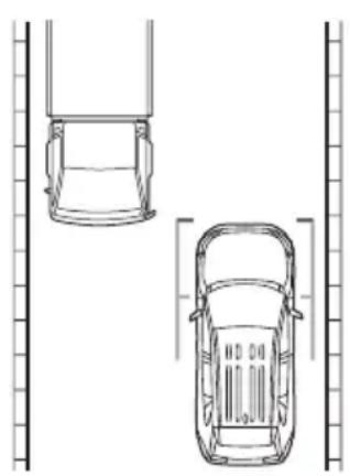
natural_image
Top-down line drawing of two cars viewed from the side of a vertical wall (no text or symbols)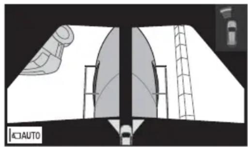
natural_image
Diagram of a vehicle interior showing a car, air ducts, and a ladder (no text or symbols)- Check the positions and distance between the vehicle width guide line and a target object such as the obstacle or curb of the road.
text_image
AUTO- Pull over to the curb as shown in the illustration above, taking care not to let the vehicle width guide line overlap the
target object.
- Ensure that the vehicle width guide line is parallel to the target object.
Checking the rear and around the vehicle
The rear view & panoramic view screen, the wide rear view screen and the rear view screen provide support when checking the areas of behind the vehicle and around the vehicle while backing up, for example while parking.
The screens will be displayed when the shift lever is in the "R" position.
Screen display
Each time the display mode switching button is selected, the mode will change as follows:
▶ Rear view & panoramic view
flowchart
graph TD
    A["Vehicle"] --> B["Top View"]
    B --> C["Drive"]
    C --> D["Drive"]
    D --> E["Brake!"]
    style A fill:#f9f,stroke:#333
    style E fill:#bbf,stroke:#333
A Intuitive parking assist
When a sensor detects an obstacle, the direction of and the approximate distance to the obstacle are displayed and the buzzer sounds.
B Rear Cross Traffic Alert
When a sensor detects an obstacle, the direction of obstacle is displayed and the buzzer sounds.
C Guide line switching button
Select to switch the guide line mode. (→P.348)
D Display mode switching button
Each time the display mode switching button is selected, the mode will change between the rear view & panoramic view mode, the wide rear view mode and rear view mode.
E Parking Support Brake*
When the system determines that the possibility of a collision with a detected object is high, a warning message is displayed.
*: If equipped
▶ Wide rear view
text_image
A B D E BRAKE! CA Intuitive parking assist
When a sensor detects an obstacle, the direction of and the approximate
distance to the obstacle are displayed and the buzzer sounds.
B Rear Cross Traffic Alert
When a sensor detects an obstacle, the direction of obstacle is displayed and the buzzer sounds.
C Guide line switching button
Select to switch the guide line mode. (→P.348)
D Display mode switching button
Each time the display mode switching button is selected, the mode will change between the rear view & panoramic view mode, the wide rear view mode and rear view mode.
E Parking Support Brake*
When the system determines that the possibility of a collision with a detected object is high, a warning message is displayed.
*: If equipped
▶ Rear view
text_image
A B D E BRAKE! CA Intuitive parking assist
When a sensor detects an obstacle, the direction of and the approximate distance to the obstacle are displayed and the buzzer sounds.
B Rear Cross Traffic Alert
When a sensor detects an obstacle, the direction of obstacle is displayed and the buzzer sounds.
C Guide line switching button
Select to switch the guide line mode. (→P.348)
D Display mode switching button
Each time the display mode switching button is selected, the mode will change between the rear view & panoramic view mode, the wide rear view mode and rear view mode.
E Parking Support Brake*
When the system determines that the possibility of a collision with a detected object is high, a warning message is displayed.
*: If equipped
- The monitor is canceled when the shift lever is shifted into any position other than the "R" position.
For details about the intuitive parking assist ( P.291), Rear Cross Traffic Alert function ( P.288) and Parking Support Brake ^* function. ( P.298)
● The display position of the intuitive parking assist and the position of obstacles displayed in the camera image do not match.
*: If equipped

WARNING
- When a sensor indicator on the intuitive parking assist display illuminates in red or a buzzer sounds continuously, be sure to check the area around the vehicle immediately and do not proceed any further until safety has been ensured, otherwise an unexpected accident may occur.
As the intuitive parking assist display and Rear Cross Traffic Alert display are displayed over the camera view, it may be difficult to see the intuitive parking assist display and Rear Cross Traffic Alert display depending on the color and brightness of the surrounding area.
Guide lines displayed on the screen
Each time the guide line switching button is selected, the mode will change as follows:
▶ Estimated course line
Estimated course lines are displayed which move in accordance with the operation of the steering wheel.
Shows distance in front of the vehicle.
- Display points approximately 3 ft. (1 m) from the edge of the bumper.
B Estimated course lines
Shows an estimated course when the steering wheel is turned.
C Distance guide lines
Shows the distance behind the vehicle when the steering wheel is turned.
• The guide lines move in conjunction with the estimated course lines.
- The guide lines display points approximately 1.5 ft. (0.5 m) (red) and approximately 3 ft. (1 m) (yellow) from the center of the edge of the bumper.
D Distance guide line
Shows the distance behind the vehicle.
- Displays a point approximately 1.5 ft. (0.5 m) (blue) from the edge of the bumper.
E Vehicle width guide lines
Displays a guide path when the vehicle is being backed straight up.
F Vehicle center guide line
Indicates the estimated vehicle center on the ground.
Parking assist guide line
The steering wheel return points (parking assist guide lines) are displayed.
This mode is recommended for those who are comfortable with parking the vehicle without the aid of the estimated course lines.
text_image
E A D B C BA Distance guide lines
Shows distance in front of the vehicle.
- Display points approximately 3 ft. (1 m) from the edge of the bumper.
B Distance guide line
Shows the distance behind the vehicle.
- Displays a point approximately 1.5 ft. (0.5 m) (red) from the edge of the bumper.
C Vehicle center guide line
Indicates the estimated vehicle center on the ground.
D Vehicle width guide lines
Displays a guide path when the vehicle is being backed straight up.
E Parking assist guide lines
Shows the path of the smallest turn possible behind the vehicle.
▶ Distance guide line
Only distance guide line is displayed.
This mode is recommended for those who are comfortable with parking the vehicle without the aid of the guide lines.
text_image
A B BA Distance guide lines
Shows distance in front of the vehicle.
- Display points approximately 3 ft. (1 m) from the edge of the bumper.
B Distance guide line
Shows the distance behind the vehicle.
- Displays a point approximately 1.5 ft. (0.5 m) (red) from the edge of the bumper.
● The display position of the intuitive parking assist and the position of obstacles displayed in the camera image do not match.

WARNING
- Depending on the circumstances of the vehicle (number of passengers, amount of luggage, etc.), the position of the guide lines displayed on the screen may change. Be sure to check visually around the vehicle before proceeding.
- If the steering wheel is straight and the vehicle width guide lines and the estimated course lines are not in alignment, have the vehicle inspected by your Toyota dealer.

WARNING
- Do not use the system if the display is incorrect due to an uneven (hilly) road or a non-straight (curvy) road.
Parking
Using the estimated course line
When parking in a space which is in the reverse direction to the space described in the procedure below, the steering directions will be reversed.
1 Shift the shift lever to the "R" position.
2 Turn the steering wheel so that the estimated course lines are within the parking space, and back up slowly.
text_image
Diagram illustrating vehicle collision and parking motion with labeled points A and B, showing top-down and side-view views.A Parking space
B Estimated course lines
3 When the rear position of the vehicle has entered the parking space, turn the steering wheel so that the vehicle width guide lines are within the left and right dividing lines of the parking space.
natural_image
Top-down diagram showing three cars with parking structures and a close-up of a car's roof structure (no text or symbols)A Vehicle width guide line
4 Once the vehicle width guide lines and the parking space lines are parallel, straighten the steering wheel and back up slowly until the vehicle has completely entered the parking space.
5 Stop the vehicle in an appropriate place, and finish parking.
Using parking assist guide line
When parking in a space which is in the reverse direction to the space described in the procedure below, the steering directions will be reversed.
1 Shift the shift lever to the "R" position.
2 Back up until the parking assist guide line meets the edge of the dividing line of the parking space.
natural_image
Top-down diagram of a car collision with two cars parked in the ground (no text or symbols)
text_image
B AA Parking assist guide line
B Parking space dividing line
3 Turn the steering wheel all the way to the left, and back up slowly.
4 Once the vehicle is parallel with the parking space, straighten the steering wheel and back up slowly until the vehicle has completely entered the parking space.
5 Stop the vehicle in an appropriate place, and finish parking.
When folding the outside rear view mirrors
Even when outside rear view mirrors are stored, the monitor can display various images of the vicinity of the vehicle and assist the operation in the confirming safe conditions in a narrow places, parking, etc.
Screen display
▶ Wide front view & side views
natural_image
Diagram of a car interior with labeled components and no readable text or symbols▶ Rear view & side views
natural_image
Diagram of a triangular structure with supports and a labeled section A, alongside icons for lighting, equipment, and support symbols (no readable text or labels)A Intuitive parking assist
When a sensor detects an obstacle, the direction of and the approximate distance to the obstacle are displayed and the buzzer sounds.
●For details about the front view and the rear view: →P.340, 345

WARNING
- When a sensor indicator on the intuitive parking assist display illuminates in red or a buzzer sounds continuously, be sure to check the area around the vehicle immediately and do not proceed any further until safety has been ensured, otherwise an unexpected accident may occur.
Magnifying function
If displayed objects are too small to see clearly when the panoramic view is displayed, the area around any of the 4 corners of the vehicle can be magnified.
Magnifying the display
1 Turn the intuitive parking assist on.
2 Select the area on the panoramic view display you wish to magnify.
natural_image
Top-down diagram of a car's front view and side profile, showing dashboard, steering wheel, and dashboard (no text or symbols)- Touching one of the 4 areas within the dotted lines will magnify that area. (Dotted lines are not displayed on the actual display.)
● To return to the normal view, touch the panoramic view display again.
●The magnifying function is enabled when all of the following conditions are met:
- The wide front view & panoramic view or the rear view & panoramic view is displayed.
• The vehicle speed is below approximately 7 mph (12 km/h).
- The intuitive parking assist is available.
●In the following situations, the magnified display will be canceled automatically:
• The vehicle speed is approximately 7 mph (12 km/h) or higher.
- The intuitive parking assist is unavailable.
- When the display is magnified, the guide lines will not be displayed.
Customizing the pan- oramic view monitor
The color of the vehicle dis-
played on the panoramic view monitor can be changed.
Changing the body color displayed in the pan-oramic view monitor
1 Display the moving view/see-through view screen. (→P.339)
2 Select

3 Select the desired color.
natural_image
Four grayscale car images arranged in a 2x2 grid, with a labeled point A pointing to the bottom-right corner (no text or symbols on cars)A Displays the next page
Panoramic view monitor precautions
Area displayed on screen
Area of image of panoramic view
The panoramic view monitor displays an image of the surrounding view of the vehicle.
Since the panoramic view processes and displays images based on flat road surfaces, it cannot depict the position of three-dimension objects (such as vehicle bumpers, etc.) that are in positions higher than the surface of the road. Even if there is room between the bumpers of the vehicles and it seems not likely to collide in the image, in reality, the both vehicles are on a collision course.
Check the safety of the surroundings directly.
text_image
Diagram illustrating car safety inspection with labeled components A and a 3D vehicle model on a road surfaceA Objects located in the shaded areas will not be displayed on the screen.
text_image
Diagram illustrating car parking and parking system with labeled components A and a 3D car model on a platform.A Parts of objects which extend above a certain height cannot be displayed on the screen.
As the images obtained from four cameras are processed and displayed on the standard of a flat road surface; the panoramic view/moving view/see through view may be displayed as follows.
- Objects may look collapsed; thinner or bigger than usual.
- An object with a higher position than the road surface may look farther away than it actually is or may not appear at all.
- Tall objects may appear protruding from the non-displayed areas of the image.
● Variations in the brightness of the image may appear for every camera.
● The displayed image may be shifted by inclination of the vehicle body, change in vehicle height, etc., depending on the number of passengers, amount of luggage, fuel quantity, etc.
- If the front doors or back door are not completely closed; neither the image nor the guide lines are displayed.
● The position relations of the vehicle icon and the road surface or obstacle may differ from the actual positions.
● The black areas of the vicinity of the vehicle icon are areas that are not captured by the camera.
● Images like the following are combined, thus some areas may be difficult to view.
natural_image
Top-down diagram of a car parked on a road with four surrounding areas (no text or symbols)
WARNING
- When a sensor indicator on the intuitive parking assist display illuminates in red or a buzzer sounds continuously, be sure to check the area around the vehicle immediately and do not proceed any further until safety has been ensured, otherwise an unexpected accident may occur.
Area of the image captured by the camera
▶ Wide front view
text_image
Diagram illustrating car safety surveillance with top-down view, front view of a vehicle, and bottom-right view showing detection of a car.▶ Side view
natural_image
Diagram showing a car on the left and its side view of a vehicle interior with a cylindrical component, no text or symbols present.▶ Rear view
text_image
Diagram illustrating vehicle safety and parking system with labeled components and safety symbolsA The area around both corners of the bumper will not be displayed.
▶ Wide rear view
text_image
Diagram illustrating vehicle parking and parking layout with labeled components and directional arrowsA The area around both cor-
ners of the bumper will not be displayed.
●Black masking is done for distance detection differences to the front of the vehicle.
●The area covered by the camera is limited. Objects which are close to either corner of the bumper or under the bumper cannot be seen on the screen.
●The area displayed on the screen may vary depending on vehicle orientation or road conditions.
●The camera uses a special lens. The distance in the image displayed on the screen will differ from the actual distance.
The camera
The cameras for the panoramic view monitor are located as shown in the illustrations.
Front camera
natural_image
Line drawing of a car interior showing a button and a close-up of the door (no text or symbols)▶ Side cameras
natural_image
Line drawing of a car interior showing the door and side mirror (no text or symbols)▶ Rear camera
natural_image
Technical line drawing of a mechanical component with an inset close-up showing a detail (no text or symbols)Using the camera
If dirt or foreign matter (such as water droplets, snow, mud, etc.) is adhering to the camera, it cannot transmit a clear image. In this case, flush it with a large quantity of water and wipe the camera lens clean with a soft and wet cloth.

NOTICE
●The panoramic view monitor may not operate properly in the following cases.
- If the camera is hit, the position and mounting angle of the camera may change.
- As the camera has a water proof construction, do not detach, disassemble or modify it. This may cause incorrect operation.
- When cleaning the camera lens, flush the camera with a large quantity of water and wipe it with a soft and wet cloth. Strongly rubbing the camera lens may cause the camera lens to be scratched and unable to transmit a clear image.
- Do not allow an organic solvent, car wax, window cleaner or a glass coating to adhere to the camera. If this happens, wipe it off as soon as possible.
- If the temperature changes rapidly, such as when hot water is poured on the vehicle in cold weather, the system may not operate normally.
- When washing the vehicle, do not apply intensive bursts of water to the camera or camera area. Doing so may result in the camera malfunctioning.
- Do not expose the camera to strong impacts as this could cause a malfunction. If this happens, have the vehicle inspected by your Toyota dealer as soon as possible.
Difference between the screen and the actual road
● The distance guide lines and the vehicle width guide lines
may not actually be parallel with the dividing lines of the parking space, even when they appear to be so. Be sure to check visually.
- The distances between the vehicle width guide lines and the left and right dividing lines of the parking space may not be equal, even when they appear to be so. Be sure to check visually.
- The distance guide lines give a distance guide for flat road surfaces. In any of the following situations, there is a margin of error between the guide lines on the screen and the actual distance/course on the road.
When the ground behind the vehicle slopes up sharply
The distance guide lines will appear to be closer to the vehicle than the actual distance. Because of this, objects will appear to be farther away than they actually are. In the same way, there will be a margin of error between the guidelines and the actual distance/course on the road.
natural_image
Diagram showing a car on a ramp and its exterior view of a car with visible exhaust pipes (no text or symbols)When the ground behind the vehicle slopes down sharply
The distance guide lines will appear to be farther from the vehicle than the actual distance. Because of this, objects will appear to be closer than they actually are. In the same way, there will be a margin of error between the guidelines and the actual distance/course on the road.
natural_image
Diagram showing a car on a road with a sensor and its 3D view, including a close-up of the sensor and ground reference (no text or symbols)When any part of the vehicle sags
When any part of the vehicle sags due to the number of passengers or the distribution of the load, there is a margin of error between the guide lines on the screen and the actual distance/course on the road.
text_image
Diagram showing a car approaching a road with a sensor or detection system labeled 'A' connected to a ground reference.A margin of error
Distortion of three-dimensional objects on the screen
When there are three-dimensional objects (such as vehicle bumpers, etc.) nearby in positions higher than the surface of the road, take extra care when using the following.
Panoramic view display (including magnified display)
Since the panoramic view processes and displays images based on flat road surfaces, it cannot depict the position of three-dimension objects (such as vehicle bumpers, etc.) that are in positions higher than the surface of the road. For example, even though it appears that there is space between the bumpers of the two vehicles in the illustration below and they are not likely to collide, in reality, a collision is about to occur.
natural_image
Diagram showing a car detection setup with a targeting device and a vehicle, no text or symbols present.
natural_image
Illustration of a robotic arm interacting with a device, showing motion lines and control panel (no text or symbols)
natural_image
Top-down diagram of two cars with an arrow indicating direction, no text or symbols present
WARNING
- When a sensor indicator on the intuitive parking assist display illuminates in red or a buzzer sounds continuously, be sure to check the area around the vehicle immediately and do not proceed any further until safety has been ensured, otherwise an unexpected accident may occur.
When approaching three-dimensional objects
The estimated course lines target flat surfaced objects (such as the road). It is not possible to determine the position of three-dimensional objects (such as vehicles) using the estimated course lines and distance guide lines. When approaching a three-dimensional object that extends outward (such as the flatbed of a truck), be careful of the following.

WARNING
- When a sensor indicator on the intuitive parking assist display illuminates in red or a buzzer sounds continuously, be sure to check the area around the vehicle immediately and do not proceed any further until safety has been ensured, otherwise an unexpected accident may occur.
Estimated course lines
Since the estimated course line is displayed for a flat road surface, it cannot depict the position of three-dimensional objects (such as vehicle bumpers, etc.) that are in positions higher than
the surface of the road. Even if the bumpers of the vehicle is on the outside of the estimated course line in the image, in reality, the vehicles are on a collision course.
text_image
Diagram illustrating car collision and navigation, showing a moving car with directional arrow and vehicle detection screen labeled 'AUTO' and 'A'.A Estimated course line
Three-dimensional objects (such as the overhang of a wall or loading platform of a truck) in high positions may not be projected on the screen. Check the safety of the surroundings directly.
text_image
Diagram illustrating car parking and parking collision scenarios with labeled vehicle positions and safety indicatorsVisually check the surroundings and the area behind the vehicle. In the case shown below, the truck appears to be outside of the estimated course lines and the vehicle does not look as if it hits the truck. However, the rear body of the truck may actually cross over the estimated course lines. In reality if you back up as guided by the estimated course lines, the vehicle may hit the truck.
natural_image
Top-down diagram of a car being tested with a ramp, showing structural components and safety symbols (no text or labels)A Estimated course lines
Distance guide lines
Visually check the surroundings and the area behind the vehicle. On the screen, it appears that a truck is parking at point B However, in reality if you back
up to point A you will hit the truck. On the screen, it appears that A is closest and is farthest away. However, in reality, the distance to A and is the same, and B is farther than A and C
text_image
Diagram illustrating vehicle collision and parking system with labeled components A, B, C and a 3D indoor enclosure viewThings you should know
If you notice any symptoms
If you notice any of the following symptoms, refer to the likely cause and the solution, and re-check.
If the symptom is not resolved by the solution, have the vehicle inspected by your Toyota dealer.
| Symptom Likely cause Solution | ||
| The image is difficult to see | The vehicle is in a dark areaThe temperature around the lens is either high or lowThe outside temperature is lowThere are water droplets on the cameraIt is raining or humidForeign matter (mud, etc.) is adhering to the cameraSunlight or headlights are shining directly into the cameraThe vehicle is under fluorescent lights, sodium lights, mercury lights, etc. | Back up while visually checking the vehicle's surroundings. (Use the monitor again once conditions have been improved.)The procedure for adjusting the picture quality of the panoramic view monitor system is the same as the procedure for adjusting the screen display. (→P.400) |
| The image is blurry | Dirt or foreign matter (such as water droplets, snow, mud, etc.) is adhering to the camera. | Flush the camera with a large quantity of water and wipe the camera lens clean with a soft and wet cloth. |
| The image is out of alignment | The camera or surrounding area has received a strong impact. | Have the vehicle inspected by your Toyota dealer. |
| The guide lines are very far out of alignment | The camera position is out of alignment. | Have the vehicle inspected by your Toyota dealer. |
| The vehicle is tilted.(There is a heavy load on the vehicle, tire pressure is low due to a tire puncture, etc.)The vehicle is used on an incline. | If this happens due to these causes, it does not indicate a malfunction.Back up while visually checking the vehicle's surroundings. | |
| The estimated course lines move even though the steering wheel is straight | There is a malfunction in the signals being output by the steering sensor. | Have the vehicle inspected by your Toyota dealer. |
| Guide lines are not displayed | The back door is open. | Close the back door. If this does not resolve the symptom, have the vehicle inspected by your Toyota dealer. |
| The estimated course lines are not displayed | 12-volt battery has been reinstalled.The steering wheel has been moved while the 12-volt battery was being reinstalled.12-volt battery power is low.The steering sensor has been reinstalled.There is a malfunction in the signals being output by the steering sensor. | Have the vehicle inspected by your Toyota dealer. |
| The panoramic view display cannot be magnified | The intuitive parking assist may be malfunctioning or dirty. | Follow the correction procedures for malfunctions of the intuitive parking assist.(→P.291) |
| The see-through view/moving view cannot be displayed | ||
Product license
This product contains eT-Kernel Multi-Core Edition ^TM real-time OS of eSOL Co., Ltd. Copyright (c) 2020 eSOL Co., Ltd.
eT-Kernel Multi-Core Edition ^TM is a trademark of eSOL Co., Ltd in Japan.
T-Kernel This Product uses the Source Code of T-Kernel under T-License granted by the Tron Forum (www.tron.org).
Driving mode select switch
The driving modes can be selected to suit the driving and usage conditions.
Selecting a driving mode
text_image
1 ECO SPORT 2 3 PUSH NORMAL ECO SPORT1 Eco drive mode
Suitable for driving to improve fuel economy by more smoothly generating torque in response to accelerator pedal operations compared to normal mode and restraining air conditioning system operations (heating/cooling).
When the switch is turned to the left while not in Eco drive mode, the system switches to Eco drive mode and the Eco drive mode indicator illuminates on the multi-information display.
2 Normal mode
Suitable for normal driving.
The driving mode returns to normal mode if the switch is pressed while in Eco drive mode or sport mode.
3 Sport mode
Controls the steering feeling and hybrid system to create an acceleration response that is suitable for sporty driving. Suitable for when crisp handling is desired, such as when driving on mountainous roads.
When the switch is turned to the right while not in sport mode, the system switches to sport mode and the sport mode indicator illuminates on the multi-information display.
■When changing to a driving mode other than normal mode
●The background color of the multi-information display changes according to the selected driving mode.
- When the speedometer is set to analog display, the speedometer display color also changes. (For vehicles with the 7-inch multi-information display only)
●The color of the switch changes according to the selected driving mode. (For vehicles with the 7-inch multi-information display only)
■Air conditioning system operation in Eco drive mode
In Eco drive mode, heating/cooling operations and the fan speed is controlled to improve fuel efficiency. Perform the following procedures to increase the air conditioning performance.
●Turn eco air conditioning mode off (→P.525)
- Adjust the fan speed (→P.525)
- Cancel Eco drive mode
■ Canceling a driving mode
- Sport mode is automatically canceled and the driving mode returns to normal mode when the power switch is turned off.
● Normal mode and Eco drive mode are not canceled until another driving mode is selected. (Even if the power switch is turned off, normal mode and Eco drive mode will not be automatically canceled).
Trail Mode
Trail Mode is a system that performs integrated control for the AWD, brake and drive force control systems to assist the drive power on bumpy roads, etc.

WARNING
■Before using Trail Mode
Make sure to observe the following precautions. Failure to observe these precautions may result in an unexpected accident.
- Check that the Trail Mode indicator is illuminated before driving. Trail Mode will not operate when the indicator is off.
● Trail Mode is not intended to expand the limits of the vehicle. Thoroughly check the road conditions and drive with caution.
● Thoroughly check the road conditions before driving. As Trail Mode is suitable for driving on bumpy roads, such as those where the tire on one side spins, there is a chance that Trail Mode may not be the most appropriate for other road conditions.
Turning Trail Mode on
Press the Trail Mode switch
When the switch is pressed, Trail Mode turns on and the Trail Mode indicator illuminates on the multi-information display.
When the switch is pressed again, the Trail Mode indicator turns off.
text_image
TRAIL EEO -SPORT TRAILTrail Mode
● Trail Mode is intended for use when driving on bumpy rough roads. Do not turn the switch on in other situations.
● Trail Mode controls the vehicle so that it can use the maximum amount of drive force when driving on bumpy roads.
- If Trail Mode is continuously used for a long period of time, the load on related parts increases and the system may be unable to operate effectively.
■When Trail Mode is canceled
In the following situations, Trail Mode is automatically canceled even if it is turned on.
- When the driving mode is changed (→P.366)
●When the power switch is turned off
■During Trail Mode operation
The following types of situations may occur, but they are not malfunctions.
● Vibrations may be felt throughout the vehicle or steering wheel
● Operating noise may be heard from the engine compartment
■When an inspection at your Toyota dealer is necessary
In the following situations, the system may be malfunctioning. Have the vehicle inspected by your Toyota dealer immediately.
- When the slip indicator light illuminates while Trail Mode is on
- When the Trail Mode indicator does not illuminate even though the Trail Mode switch is pressed
Driving assist systems
To keep driving safety and performance, the following systems operate automatically in response to various driving situations. Be aware, however, that these systems are supplementary and should not be relied upon too heavily when operating the vehicle.
Summary of the driving assist systems
■ ECB (Electronically Controlled Brake System)
The electronically controlled system generates braking force corresponding to the brake operation
■ABS (Anti-lock Brake System)
Helps to prevent wheel lock when the brakes are applied suddenly, or if the brakes are applied while driving on a slippery road surface
Brake assist
Generates an increased level of braking force after the brake pedal is depressed when the system detects a panic stop situation
■VSC (Vehicle Stability Control)
Helps the driver to control skidding when swerving suddenly or turning on slippery road surfaces.
■Enhanced VSC (Enhanced Vehicle Stability Control)
Provides cooperative control of the ABS, TRAC, VSC and EPS.
Helps to maintain directional stability when swerving on slippery road surfaces by controlling steering performance.
■Trailer Sway Control
Helps the driver to control trailer sway by selectively applying brake pressure for individual wheels and reducing driving torque when trailer sway is detected.
■TRAC (Traction Control)
Helps to maintain drive power and prevent the drive wheels from spinning when starting the vehicle or accelerating on slippery roads
■Active Cornering Assist (ACA)
Helps to prevent the vehicle from drifting to the outer side by performing inner wheel brake control when attempting to accelerate while turning
■Hill-start assist control
Helps to reduce the backward
movement of the vehicle when starting on an uphill
■EPS (Electric Power Steering)
Employs an electric motor to reduce the amount of effort needed to turn the steering wheel
■E-Four (Electronic On-Demand AWD system)
Automatically switches from front wheel drive to all-wheel drive (AWD) according to the driving conditions, helping to ensure reliable handling and stability. Examples of conditions where the system will switch to AWD are when cornering, going uphill, starting off or accelerating, and when the road surface is slippery due to snow, rain, etc.
■The Secondary Collision Brake
When the SRS airbag sensor detects a collision and the system operates, the brakes and brake lights are automatically controlled to reduce the vehicle speed and help reduce the possibility of further damage due to a secondary collision.
■When the TRAC/VSC/ABS/Trailer Sway Control systems are operating
The slip indicator light will flash while the TRAC/VSC/ABS/Trailer Sway Control systems are operating.
text_image
Diagram showing car interior with steering wheel and traffic sign icon, likely indicating speed or flow direction■Disabling the TRAC system
If the vehicle gets stuck in mud, dirt or snow, the TRAC system may reduce power from the hybrid system to the wheels.
Pressing to turn the system off may make it easier for you to rock the vehicle in order to free it.
To turn the TRAC system off, quickly press and release OFF
text_image
Traction Control Turned OFF"Traction Control Turned OFF" will be shown on the multi-information display.
Press again to turn the system back on.
■Turning off the TRAC/VSC/Trailer Sway Control systems
To turn the TRAC/VSC/Trailer Sway Control systems off, press and hold
OFF for more than 3 seconds while the vehicle is stopped.
The VSC OFF indicator light will come on and the "Traction Control Turned OFF" will be shown on the multi-information display.*
Press again to turn the systems back on.
*: PCS will also be disabled (only Pre-Collision warning is available). The PCS warning light will come on and a message will be displayed on the multi-information display. (→P.257)
When the message is displayed on the multi-information display showing that TRAC has been disabled even if has not been pressed
TRAC is temporary deactivated. If the information continues to show, contact your Toyota dealer.
■ Operating conditions of hill-start assist control
When the following four conditions are met, the hill-start assist control will operate:
●The shift lever is in a position other than P or N (when starting off forward/backward on an upward incline).
●The vehicle is stopped.
●The accelerator pedal is not depressed.
●The parking brake is not engaged.
■Automatic system cancelation of hill-start assist control
The hill-start assist control will turn off in any of the following situations:
●The shift lever is shifted to P or N.
●The accelerator pedal is depressed.
●The parking brake is engaged.
● No more than 2 seconds have elapsed after the brake pedal is released.
■ Sounds and vibrations caused by the ABS, brake assist, VSC, Trailer Sway Control, TRAC and hill-start assist control systems
●A sound may be heard from the engine compartment when the brake pedal is depressed repeat-
edly, when the hybrid system is started or just after the vehicle begins to move. This sound does not indicate that a malfunction has occurred in any of these systems.
● Any of the following conditions may occur when the above systems are operating. None of these indicates that a malfunction has occurred.
- Vibrations may be felt through the vehicle body and steering.
- A motor sound may be heard also after the vehicle comes to a stop.
■ ECB operating sound
ECB operating sound may be heard in the following cases, but it does not indicate that a malfunction has occurred.
●Operating sound heard from the engine compartment when the brake pedal is operated.
- Motor sound of the brake system heard from the front part of the vehicle when the driver' door is opened.
●Operating sound heard from the engine compartment when one or two minutes passed after the stop of the hybrid system.
■Active Cornering Assist operation sounds and vibrations
When the Active Cornering Assist is operated, operation sounds and vibrations may be generated from the brake system, but this is not a malfunction.
■EPS operation sound
When the steering wheel is operated, a motor sound (whirring sound) may be heard. This does not indicate a malfunction.
■Automatic reactivation of TRAC, Trailer Sway Control and VSC systems
After turning the TRAC, Trailer Sway Control and VSC systems off, the systems will be automatically re-enabled in the following situations:
- When the power switch is turned off.
- If only the TRAC system is turned off, the TRAC will turn on when vehicle speed increases. If both the TRAC and VSC systems are turned off, automatic re-enabling will not occur when vehicle speed increases.
■Operating conditions of Active Cornering Assist
The system operates when the following occurs.
●TRAC/VSC can operate
●The driver is attempting to accelerate while turning
●The system detects that the vehicle is drifting to the outer side
●The brake pedal is released
■Reduced effectiveness of the EPS system
The effectiveness of the EPS system is reduced to prevent the system from overheating when there is frequent steering input over an extended period of time. The steering wheel may feel heavy as a result. Should this occur, refrain from excessive steering input or stop the vehicle and turn the hybrid system off. The EPS system should return to normal within 10 minutes.
■Secondary Collision Brake operating conditions
The system operates when the SRS airbag sensor detects a collision while the vehicle is in motion. However, the system does not operate in any of the following situations.
●The vehicle speed is below 6 mph (10 km/h)
Components are damaged
■ Secondary Collision Brake automatic cancellation
The system is automatically canceled in any of the following situations.
●The vehicle speed drops below approximately 6 mph (10 km/h)
● A certain amount of time elapses during operation
●The accelerator pedal is depressed a large amount
If a message about AWD is shown on the multi-information display
Perform the following actions.
| Message Details/Actions | |
| “AWD System Overheated Switching to 2WD Mode” | AWD system is overheating.→ Stop the vehicle in a safe place and let the engine idle.Once the display message on the multi-information display turns off, there is no problem continuing to drive.If the message does not disappear, have your vehicle checked by your Toyota dealer immediately. |
| “AWD System Overheated 2WD Mode Engaged” | The vehicle switched from all-wheel drive (AWD) to front wheel drive due to overheating.→ Stop the vehicle in a safe place and let the engine idle.Once the display message on the multi-information display turns off, the AWD system returns to normal.If the message does not disappear, have your vehicle checked by your Toyota dealer immediately. |
| “AWD System Malfunction 2WD Mode Engaged Visit Your Dealer” | A malfunction occurred in the AWD system.→ Have your vehicle checked by your Toyota dealer immediately. |

WARNING
■The ABS does not operate effectively when
●The limits of tire gripping performance have been exceeded (such as excessively worn tires on a snow covered road).
●The vehicle hydroplanes while driving at high speed on wet or slick roads.
■Stopping distance when the ABS is operating may exceed that of normal conditions
The ABS is not designed to shorten the vehicle's stopping distance. Always maintain a safe distance from the vehicle in front of you, especially in the following situations:
- When driving on dirt, gravel or snow-covered roads
●When driving with tire chains - When driving over bumps in the road

WARNING
- When driving over roads with potholes or uneven surfaces
■TRAC/VSC may not operate effectively when
Directional control and power may not be achievable while driving on slippery road surfaces, even if the TRAC/VSC system is operating. Drive the vehicle carefully in conditions where stability and power may be lost.
■Active Cornering Assist does not operate effectively when
- Do not overly rely on Active Cornering Assist. Active Cornering Assist may not operate effectively when accelerating down slopes or driving on slippery road surfaces.
- When Active Cornering Assist frequently operates, Active Cornering Assist may temporarily stop operating to ensure proper operation of the brakes, TRAC and VSC.
■ Hill-start assist control does not operate effectively when
- Do not overly rely on hill-start assist control. Hill-start assist control may not operate effectively on steep inclines and roads covered with ice.
●Unlike the parking brake, hill-start assist control is not intended to hold the vehicle stationary for an extended period of time. Do not attempt to use hill-start assist control to hold the vehicle on an incline, as doing so may lead to an accident.
■When the TRAC/ABS/VSC/Trailer Sway Control is activated
The slip indicator light flashes. Always drive carefully. Reckless driving may cause an accident. Exercise particular care when the indicator light flashes.
■When the TRAC/VSC/Trailer Sway Control systems are turned off
Be especially careful and drive at a speed appropriate to the road conditions. As these are the systems to help ensure vehicle stability and driving force, do not turn the TRAC/VSC/Trailer Sway Control systems off unless necessary.
Trailer Sway Control is part of the VSC system and will not operate if VSC is turned off or experiences a malfunction.
■Replacing tires
Make sure that all tires are of the specified size, brand, tread pattern and total load capacity. In addition, make sure that the tires are inflated to the recommended tire inflation pressure level. The ABS, TRAC and VSC/Trailer Sway Control systems will not function correctly if different tires are installed on the vehicle. Contact your Toyota dealer for further information when replacing tires or wheels.
■Handling of tires and the sus-pension
Using tires with any kind of problem or modifying the suspension will affect the driving assist systems, and may cause a system to malfunction.

WARNING
■Trailer Sway Control precaution
The Trailer Sway Control system is not able to reduce trailer sway in all situations. Depending on many factors such as the conditions of the vehicle, trailer, road surface and driving environment, the Trailer Sway Control system may not be effective. Refer to your trailer owner's manual for information on how to tow your trailer properly.
■If trailer sway occurs
Observe the following precautions.
Failing to do so may cause death or serious injury.
- Firmly grip the steering wheel. Steer straight ahead. Do not try to control trailer swaying by turning the steering wheel.
●Begin releasing the accelerator pedal immediately but very gradually to reduce speed. Do not increase speed. Do not apply vehicle brakes.
If you make no extreme correction with the steering or brakes, your vehicle and trailer should stabilize. (→P.200)
■Secondary Collision Brake
Do not rely solely upon the Secondary Collision Brake. This system is designed to help reduce the possibility of further damage due to a secondary collision, however, that effect changes according to various conditions. Overly relying on the system may result in death or serious injury.
Hybrid vehicle driving tips
For economical and ecological driving, pay attention to the following points:
Using Eco drive mode
When using Eco drive mode, the torque corresponding to the accelerator pedal depression amount can be generated more smoothly than it is in normal conditions. In addition, the operation of the air conditioning system (heating/cooling) will be minimized, improving the fuel economy. (→P.366)
Use of Hybrid System Indicator
The Eco-friendly driving is possible by keeping the indicator of Hybrid System Indicator within Eco area. ( P.95, 100)
Shift lever operation
Shift the shift lever to D when stopped at a traffic light, or driving in heavy traffic etc. Shift the shift lever to P when parking. When using the N position, there is no positive effect on fuel consumption. In the N position, the gasoline engine operates but electricity cannot be generated. Also, when using the air conditioning system, etc., the hybrid battery (traction battery) power is consumed.
Accelerator pedal/brake pedal operation
- Drive your vehicle smoothly. Avoid abrupt acceleration and deceleration. Gradual acceleration and deceleration will make more effective use of the electric motor (traction motor) without having to use gasoline engine power.
- Avoid repeated acceleration. Repeated acceleration consumes hybrid battery (traction battery) power, resulting in poor fuel consumption. Battery power can be restored by driving with the accelerator pedal slightly released.
When braking
Make sure to operate the brakes gently and in a timely manner. A greater amount of electrical energy can be regenerated when slowing down.
Delays
Repeated acceleration and deceleration, as well as long waits at traffic lights, will lead to bad fuel economy. Check traffic reports before leaving and avoid delays as much as possible.
When driving in a traffic jam, gently release the brake pedal to allow the vehicle to move forward slightly while avoiding overuse of the accelerator pedal. Doing so can help control excessive gasoline consumption.
Highway driving
Control and maintain the vehicle at a constant speed. Before stopping at a toll booth or similar, allow plenty of time to release the accelerator and gently apply the brakes. A greater amount of electrical energy can be regenerated when slowing down.
Air conditioning
Use the air conditioning only when necessary. Doing so can help reduce excessive gasoline consumption.
In summer: When the ambient temperature is high, use the recirculated air mode. Doing so will help to reduce the burden on the air conditioning system and reduce fuel consumption as well.
In winter: Because the gasoline engine will not automatically cut out until it and the interior of the vehicle are warm, it will consume fuel. Also, fuel consumption can be improved by avoiding overuse of the heater.
Checking tire inflation pressure
Make sure to check the tire inflation pressure frequently. Improper tire inflation pressure can cause poor fuel economy. Also, as snow tires can cause large amounts of friction, their use on dry roads can lead to poor fuel economy. Use tires that are appropriate for the season.
Luggage
Carrying heavy luggage will lead to poor fuel economy. Avoid carrying unnecessary luggage. Installing a large roof rack will also cause poor fuel economy.
Warming up before driving
Since the gasoline engine starts up and cuts out automatically when cold, warming up the engine is unnecessary. Moreover, frequently driving short distances will cause the engine to repeatedly warm up, which can lead to excess fuel consumption.
Winter driving tips
Carry out the necessary preparations and inspections before driving the vehicle in winter. Always drive the vehicle in a manner appropriate to the prevailing weather conditions.
Pre-winter preparations
- Use fluids that are appropriate to the prevailing outside temperatures.
- Engine oil
- Engine coolant
• Power control unit coolant - Washer fluid
● Have a service technician inspect the condition of the 12-volt battery.
● Have the vehicle fitted with four snow tires or purchase a set of tire chains for the front tires.
Ensure that all tires are the same size and brand, and that chains match the size of the tires.

WARNING
■Driving with snow tires
Observe the following precautions to reduce the risk of accidents. Failure to do so may result in a loss of vehicle control and cause death or serious injury.
● Use tires of the specified size.
●Maintain the recommended level of air pressure.
- Do not drive in excess of 75 mph (120 km/h), regardless of the type of snow tires being used.
- Use snow tires on all, not just some wheels.
■Driving with tire chains
Observe the following precautions to reduce the risk of accidents. Failure to do so may result in the vehicle being unable to be driven safely, and may cause death or serious injury.
- Do not drive in excess of the speed limit specified for the tire chains being used, or 30 mph (50 km/h), whichever is lower.
● Avoid driving on bumpy road surfaces or over potholes.
● Avoid sudden acceleration, abrupt steering, sudden braking and shifting operations that cause sudden engine braking.
● Slow down sufficiently before entering a curve to ensure that vehicle control is maintained.
- Do not use LTA (Lane Tracing Assist) system.

NOTICE
■Repairing or replacing snow tires (vehicles with tire pressure warning system)
Request repairs or replacement of snow tires from your Toyota dealer or legitimate tire retailers. This is because the removal and attachment of snow tires affects the operation of the tire pressure warning valves and transmitters.
Before driving the vehicle
Perform the following according to the driving conditions:
- Do not try to forcibly open a window or move a wiper that is frozen. Pour warm water over the frozen area to melt the ice. Wipe away the water immediately to prevent it from freezing.
- To ensure proper operation of the climate control system fan, remove any snow that has accumulated on the air inlet vents in front of the windshield.
- Check for and remove any excess ice or snow that may have accumulated on the exterior lights, vehicle's roof, chassis, around the tires or on the brakes.
- Remove any snow or mud from the bottom of your shoes before getting in the vehicle.
When driving the vehicle
Accelerate the vehicle slowly, keep a safe distance between you and the vehicle ahead, and drive at a reduced speed suitable to road conditions.
When parking the vehicle
- Park the vehicle and move the shift lever to P without set-
ting the parking brake. The parking brake may freeze up, preventing it from being released. If the vehicle is parked without setting the parking brake, make sure to block the wheels.
Failure to do so may be dangerous because it may cause the vehicle to move unexpectedly, possibly leading to an accident.
When the parking brake is in automatic mode, release the parking brake after shifting the shift lever to P. ( P.224)
- If the vehicle is left parked with the brakes damp in cold temperatures, there is a possibility of the brakes freezing.
- If the vehicle is parked without setting the parking brake, confirm that the shift lever cannot be moved out of P*.
*: The shift lever will be locked if it is attempted to be shifted from P to any other position without depressing the brake pedal. If the shift lever can be shifted from P, there may be a problem with the shift lock system. Have the vehicle inspected by your Toyota dealer immediately.

WARNING
■When parking the vehicle
When parking the vehicle without applying the parking brake, make sure to chock the wheels. If you do not chock the wheels, the vehicle may move unexpectedly, possibly resulting in an accident.
Selecting tire chains
Use the correct tire chain size when mounting the tire chains. Chain size is regulated for each tire size.
text_image
A B C E F DSide chain:
A 0.12 in. (3 mm) in diameter
B 0.39 in. (10 mm) in width
C 1.18 in. (30 mm) in length
Cross chain:
D 0.16 in. (4 mm) in diameter
E 0.55 in. (14 mm) in width
F 0.98 in. (25 mm) in length
Regulations on the use of tire chains
Regulations regarding the use of tire chains vary depending on location and type of road.
Always check local regulations before installing chains.
■Tire chain installation
Observe the following precautions when installing and removing chains:
● Install and remove tire chains in a safe location.
● Install tire chains on the front tires only. Do not install tire chains on the rear tires.
● Install tire chains on front tires as tightly as possible. Retighten chains after driving 1/4 - 1/2 mile (0.5 - 1.0 km).
● Install tire chains following the instructions provided with the tire chains.

NOTICE
■ Fitting tire chains (vehicles with tire pressure warning system)
The tire pressure warning valves and transmitters may not function correctly when tire chains are fitted.
Utility vehicle precautions
This vehicle belongs to the utility vehicle class, which has higher ground clearance and narrower tread in relation to the height of its center of gravity to make it capable of performing in a wide variety of off-road applications.
Utility vehicle feature
- Specific design characteristics give it a higher center of gravity than ordinary passenger cars. This vehicle design feature causes this type of vehicle to be more likely to rollover. And, utility vehicles have a significantly higher rollover rate than other types of vehicles.
- An advantage of the higher ground clearance is a better view of the road allowing you to anticipate problems.
- It is not designed for cornering at the same speeds as ordinary passenger cars any more than low-slung sports cars are designed to perform satisfactorily under off-road conditions. Therefore, sharp turns at excessive speeds may cause the vehicle to roll-over.

WARNING
■ Utility vehicle precautions
Always observe the following precautions to minimize the risk of death, serious injury or damage to your vehicle:
In a rollover crash, an unbelted person is significantly more likely to die than a person wearing a seat belt. Therefore, the driver and all passengers should always fasten their seat belts.
● Avoid sharp turns or abrupt maneuvers, if at all possible. Failure to operate this vehicle correctly may result in loss of control or vehicle rollover causing death or serious injury.
- Loading cargo on the roof luggage carrier (if equipped) will make the center of the vehicle gravity higher. Avoid high speeds, sudden starts, sharp turns, sudden braking or abrupt maneuvers, otherwise it may result in loss of control or vehicle rollover due to failure to operate this vehicle correctly.
● Always slow down in gusty crosswinds. Because of its profile and higher center of gravity, your vehicle is more sensitive to side winds than an ordinary passenger car. Slowing down will allow you to have better control.
- Do not drive horizontally across steep slopes. Driving straight up or straight down is preferred. Your vehicle (or any similar off-road vehicle) can tip over sideways much more easily than forward or backward.
Off-road driving
When driving your vehicle off-
road, please observe the following precautions to ensure your driving enjoyment and to help prevent the closure of areas to off-road vehicles:
● Drive your vehicle only in areas where off-road vehicles are permitted to travel.
- Respect private property. Get owner's permission before entering private property.
- Do not enter areas that are closed. Honor gates, barriers and signs that restrict travel.
- Stay on established roads. When conditions are wet, driving techniques should be changed or travel delayed to prevent damage to roads.
■ Additional information for off-road driving
For owners in U.S. mainland, Hawaii and Puerto Rico:
To obtain additional information pertaining to driving your vehicle off-road, consult the following organizations:
• State and Local Parks and Recreation Departments
• State Motor Vehicle Bureau
• Recreational Vehicle Clubs
• U.S. Forest Service and Bureau of Land Management

WARNING
■Off-road driving precautions
Always observe the following precautions to minimize the risk of death, serious injury or damage to your vehicle:
●Drive carefully when off the road. Do not take unnecessary risks by driving in dangerous places.
- Do not grip the steering wheel spokes when driving off-road. A bad bump could jerk the wheel and injure your hands. Keep both hands and especially your thumbs on the outside of the rim.
●Always check your brakes for effectiveness immediately after driving in sand, mud, water or snow.
● After driving through tall grass, mud, rock, sand, rivers, etc., check that there is no grass, bush, paper, rags, stone, sand, etc. adhering or trapped on the underbody. Clear off any such matter from the underbody. If the vehicle is used with these materials trapped or adhering to the underbody, a breakdown or fire could occur.

WARNING
- When driving off-road or in rugged terrain, do not drive at excessive speeds, jump, make sharp turns, strike objects, etc. This may cause loss of control or vehicle rollover causing death or serious injury. You are also risking expensive damage to your vehicle's suspension and chassis.

NOTICE
■To prevent the water damage
Take all necessary safety measures to ensure that water damage to the hybrid battery (traction battery), hybrid system or other components does not occur.
●Water entering the engine compartment may cause severe damage to the hybrid system. Water entering the interior may cause the hybrid battery (traction battery) stowed under the rear seats to short circuit.
●Water entering the hybrid transmission will cause deterioration in transmission quality. The malfunction indicator may come on, and the vehicle may not be drivable.
Water can wash the grease from wheel bearings, causing rusting and premature failure, and may also enter the hybrid transaxle case, reducing the gear oil's lubricating qualities.
■When you drive through water
If driving through water, such as when crossing shallow streams, first check the depth of the water and the bottom of the riverbed for firmness. Drive slowly and avoid deep water.
■Inspection after off-road driving
● Sand and mud that has accumulated around brake discs may affect braking efficiency and may damage brake system components.
● Always perform a maintenance inspection after each day of off-road driving that has taken you through rough terrain, sand, mud, or water. For scheduled maintenance information, refer to the “Scheduled Maintenance Guide” or “Owner’s Manual Supplement”.
5-1. Basic function
Buttons overview...... 387
Menu screen 389
Status icon 390
"Setup" screen ...... 392
5-2. Basic information before operation
Initial screen.... 393
Touch screen 394
Home screen...... 396
Entering letters and numbers/list screen operation 397
Screen adjustment ..... 400
Linking multi-information display and the system 401
5-3. Connectivity settings
Registering/Connecting a Bluetooth® device ..... 402
Setting Bluetooth ^® details 406
Wi-Fi ^® Hotspot 414
5-4. Apple CarPlay/Android Auto
Apple CarPlay ^® /Android Auto ^TM 419
5-5. Other settings
General settings...... 426
Voice settings...... 430
Vehicle settings ...... 431
5-6. Using the audio/visual system
Quick reference...... 432
Some basics...... 433
5-7. Radio operation
AM/FM/SiriusXM (SXM) radio 437
5-8. Media operation
USB memory...... 444
iPod/iPhone (Apple Car-Play) 446
Android Auto 449
Bluetooth ^® audio ..... 450
5-9. Audio/visual remote controls
Steering switches ..... 454
5-10.Audio settings
Setup...... 456
5-11. Tips for operating the audio/visual system
Operating information.. 458
5-12. Voice command system operation
Voice command system 470
Command list 473
5-13.Mobile Assistant operation
Mobile Assistant...... 477
5-14. Phone operation (Hands-free system for cellular phones)
Quick reference...... 479
Some basics .... 480
Placing a call using the Bluetooth® hands-free system 484
Receiving a call using the Bluetooth®hands-free system 487
Talking on the Bluetooth ^® hands-free system..... 488
Bluetooth ^® phone message function.... 490
5-15.Phone settings
Setup...... 495
5-16.What to do if... (Bluetooth®)
Troubleshooting ..... 505
5-17. Connected Services overview
Connected Services.... 509
Type A: Function achieved by using a smartphone or DCM.... 510
Type B: Function achieved by using DCM and the system 512
Type C: Function achieved by using DCM.... 513
Type D: Function achieved by using DCM and a smartphone .... 516
5-18. Connected Services operation
Toyota Apps 518
5-19.Setup
Toyota Apps settings... 522
Buttons overview
*: Vehicles with Audio only
For details about Audio Plus or Premium Audio, refer to "Navigation and Multimedia System Owner's Manual".
Operations of each part
flowchart
graph TD
    A["Power VOLUME"] --> J["H"]
    A --> I["I"]
    A --> G["G"]
    A --> F["F"]
    A --> E["E"]
    A --> B["B"]
    A --> C["C"]
    A --> D["D"]
    A --> SEEK["SEEK"]
    A --> <TRACK["<TRACK"]
    A --> PHONE["PHONE"]
    A --> APPS["APPS"]
    A --> TUNE_SCROLL["TUNE SCROLL"]
A By touching the screen with your finger, you can control the selected functions. (→P.394, 395)
B Press to seek up or down for a radio station or to access a desired track/file. (→P.437, 444, 446, 450)
C Press to access the Bluetooth® hands-free system. (→P.479)
- When an Apple CarPlay connection is established, press to display the Phone application screen. ^1
D Press to display the Toyota Apps screen. ^*1,2 (→P.518)
E Turn to change the radio station or skip to the next or previous track/file. (→P.437, 444, 446, 450)
F Press to turn the audio/visual system on and off, and turn it to adjust the volume. Press and hold to restart the system. (→P.393, 433)
G When an Apple CarPlay/Android Auto connection is established, press to display the Maps application screen. ^*1
H Press to display the audio/visual system screen. ( 432, 433)
I Press to display the "Menu" screen. (→P.389)
J Press to display the home screen. (→P.396)
*1: This function is not made available in some countries or areas.
*2: When an Apple CarPlay/Android Auto connection is established, this function will be unavailable.

WARNING
- For safety, the driver should not operate the system while he/she is driving. Insufficient attention to the road and traffic may cause an accident.
●The screen shots in this document and the actual screens of the system differ depending on whether the functions and/or a contract existed.
Menu screen
Menu screen operation
Press the "MENU" button to display the "Menu" screen.
text_image
Menu A 4:34 B Audio C Phone D Apps E Projection Info Setup F G H Display Apple CarPlay Android AutoA Displays the clock. Select to display the clock settings screen. (→P.427)
B Select to display the audio control screen. (→P.432)
C Select to display the hands-free operation screen. (→P.479)
- When an Apple CarPlay connection is established, select to display the Phone application screen. ^1
D Select to display the Toyota Apps screen. ^*1,2 ( P.518)
When an Apple CarPlay/Android Auto connection is established and this button displays “Apple CarPlay”/“Android Auto”, select to display the home screen of Apple CarPlay/Android Auto. *1 (→P.419)
F Select to display the energy monitor/consumption screen. (→P.113)
G Select to display the "Setup" screen. (→P.392)
H Select to adjust the contrast, brightness, etc. of the display. ( P.400)
*1: This function is not made available in some countries or areas.
*2: When an Apple CarPlay/Android Auto connection is established, this function will be unavailable.
Status icon
Status icons are displayed at the top of the screen.
Status icon explanation
text_image
A B C D E F DCM DCM 8:18 History Favorites Contacts Keypad Select Device MessageA Indicate during data communication performed via Data Communication Module (DCM) ^1
B The reception level of Data Communication Module (DCM) display ^1 ( P.390)
C The reception level of the connected phone display ( P.390)
D Remaining battery charge display ( P.391)
E Bluetooth® phone connection condition display (→P.391)
F Wi-Fi ^® connection condition display ^*1,2 (→P.414)
*1: Vehicles equipped with DCM
*2: This function is not made available in some countries or areas.
●The number of status icons that can be displayed differs depending on the displayed screen.
Reception level display
The level of reception does not always correspond with the level displayed on the cellular phone. The level of reception may not be displayed depending on the phone you have.
When the cellular phone is out of the service area or in a place inaccessible by radio waves,
/ is displayed.
“Rm” is displayed when receiving in a roaming area. While roaming, display “Rm” top-left on the icon.
The receiving area may not be displayed depending on the type of Bluetooth ^® phone you have.
▶ While connected with cellular phone
| Reception Level | Indicators |
| Poor | |
| Excellent |
▶ While using Data Communication Module (DCM)
| Reception Level | Indicators |
| Poor |  |
| Excellent |  |
▶ While using Wi-F ^ Hotspot
| Reception Level | Indicators |
| No connection |  |
| Connected |  |
- When Wi-Fi® Hotspot is off, no item is displayed.
Remaining battery charge display
The amount displayed does not always correspond with the amount displayed on the Bluetooth ^® device.
The amount of battery charge left may not be displayed depending on the type of the Bluetooth ^® device connected.
This system does not have a charging function.
| Remaining charge | Indicators |
| Empty | |
| Full |
Bluetooth ^® connection condition display
An antenna for the Bluetooth ^® connection is built into the instrument panel.
The condition of the Bluetooth ^® connection may deteriorate and the system may not function when a Bluetooth ^® phone is used in the following conditions and/or places:
The cellular phone is obstructed by certain objects (such as when it is behind the seat or in the glove box or console box).
The cellular phone is touching or is covered with metal materials.
Leave the Bluetooth ^® phone in a place where the condition of the Bluetooth ^® connection is good.
| Indicators Conditions | |
| (Blue) | Indicates that the condition of the Bluetooth® connection is good. |
| (Gray) | While in this condition, sound quality during phone calls may deteriorate. |
| Indicates that the cellular phone is not connected via Bluetooth®. | |
"Setup" screen
"Setup" screen
Press the "MENU" button, then select "Setup" to display the "Setup" screen. The items shown on the "Setup" screen can be set.
text_image
Setup 9:25 General A Voice Volume 4 Bluetooth B Voice Recognition Prompts High Audio C Train Voice Recognition Phone D Voice Recognition Tutorial Voice E Voice Prompt Interrupt Off Default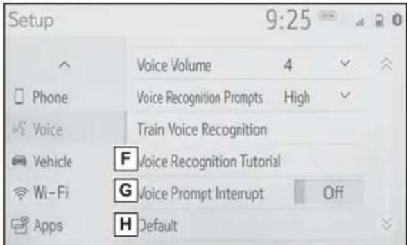
text_image
Setup 9:25 Voice Volume 4 Phone Voice Recognition Prompts High Voice Train Voice Recognition Vehicle F Voice Recognition Tutorial Wi-Fi G Voice Prompt Interrupt Off Apps H DefaultA Select to change the selected language, operation sound settings, etc. (→P.426)
B Select to set Bluetooth ^® device and Bluetooth ^® system settings. (→P.406)
C Select to set audio settings.
(→P.456)
D Select to set the phone sound, contacts, message settings, etc. (→P.495)
E Select to set the voice settings. (→P.430)
F Select to set vehicle information. (→P.431)
G Select to set Wi-Fi® connection settings. ^1,2 ( P.415)
H Select to set Toyota Apps settings. ^2 ( P.522)
*1: Vehicles equipped with DCM
*2: This function is not made available in some countries or areas.
Initial screen
When the power switch is turned to ACC or ON, the initial screen will be displayed and the system will begin operating.
Caution screen
After a few seconds, the caution screen will be displayed.
After about 5 seconds or selecting "Continue", the caution screen automatically switches to the next screen.

WARNING
- When the vehicle is stopped with the hybrid system operating, always apply the parking brake for safety.
Restarting the system
When system response is extremely slow, the system can be restarted.
1 Press and hold the "POWER VOLUME" knob for 3 seconds or more.
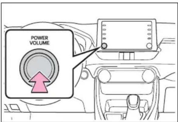
text_image
POWER VOLUMETouch screen
Touch screen gestures
Operations are performed by touching the touch screen directly with your finger.
| Operation method Outline | Main use | |
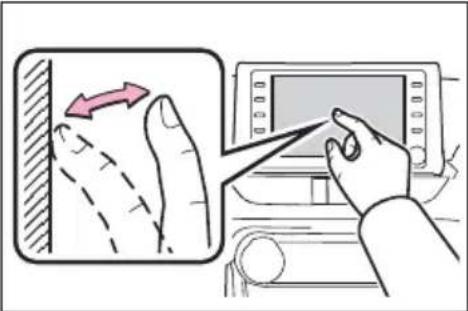 | • Touch Quickly touch and release once. | • Selecting an item on the screen |
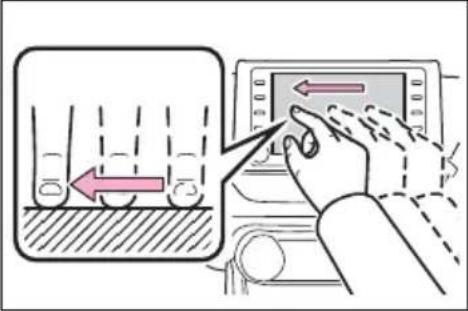 | • Drag*1 Touch the screen with your finger, and move the screen to the desired position. | • Scrolling the lists |
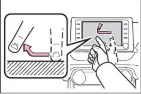 | • Flick*1 Quickly move the screen by flicking with your finger. | • Scrolling the main screen page |
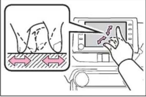 | • Pinch in/Pinch out Slide fingers toward each other or apart on the screen. | • Changing the scale of the map *2 |
*1: The above operations may not be performed on all screens.
*2: The Apple CarPlay Maps application is not compatible with pinch multi-touch gestures.
● Flick operations may not be performed smoothly at high altitudes.
Touch screen operation
This system is operated mainly by the buttons on the screen. (Referred to as screen buttons in this manual.)
When a screen button is touched, a beep sounds. (To set the beep sound: →P.426)
- If the system does not respond to touching a screen button, move your finger away from the screen and then touch it again.
●Dimmed screen buttons cannot be operated.
●The displayed image may become darker and moving images may be slightly distorted when the screen is cold.
In extremely cold conditions, the screen may not be displayed and the data input by a user may be deleted. Also, the screen buttons may be harder than usual to depress. - When you look at the screen through polarized material such as polarized sunglasses, the screen may be dark and hard to see. If so, look at the screen from different angles, adjust the screen settings on the display settings screen or take off your sunglasses.
- When is displayed on the screen, select to return to the previous screen.

NOTICE
● To prevent damaging the screen, lightly touch the screen buttons with your finger.
- Do not use objects other than your finger to touch the screen.
● Wipe off fingerprints using a glass cleaning cloth. Do not use chemical cleaners to clean the screen, as they may damage the touch screen.
Capacitive touch screen buttons
The operable areas of the capacitive touch screen buttons use capacitive touch sensors and may not operate properly in the following situations:
- If the screen is dirty or wet
- If a source of strong electromagnetic waves is brought near the screen
- If a glove is worn during operation
- If the screen is touched by a fingernail
- If a stylus is used to operate the buttons
- If your palm touches the operable area of another button during operation
- If a button is touched quickly
- If the operable part of a capacitive touch screen button is touched by or covered
with a metal object, such as the following, it may not operate properly:
• Magnetic isolation cards
• Metallic foil, such as the inner packaging of a cigarette box
• Metallic wallets or bags
- Coins
• Discs, such as a CD or DVD
- If the operable part of a capacitive touch screen button is wiped, it may operate unintentionally.
- If the capacitive touch screen button is being touched when the power switch is changed to ACC or ON, the button may not operate properly. In this case, remove anything touching the button, turn the power switch to OFF and then turn it to ACC or ON, or restart the system by press and hold the "POWER VOLUME" knob for 3 seconds or more.
●Capacitive touch screen button sensor sensitivity can be adjusted. (→P.426)
Home screen
On the home screen, multiple screens, such as the audio/visual system screen, hands-free screen and clock screen, can be displayed simultaneously.
Home screen operation
1 Press the "HOME" button.
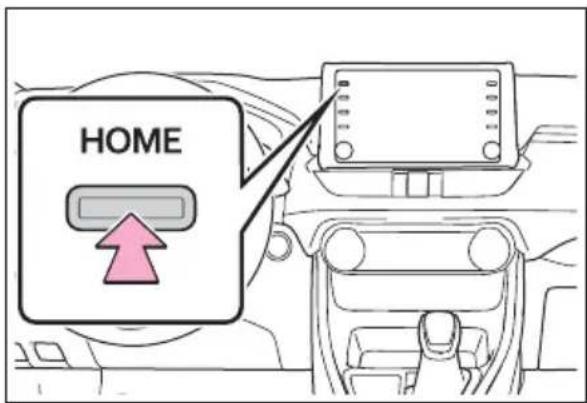
text_image
HOME2 Check that the home screen is displayed.
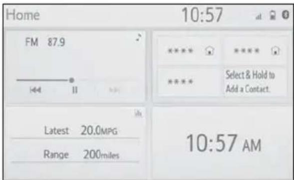
text_image
Home 10:57 FM 87.9 I-4 II Latest 20.0MPG Range 200miles 10:57 AM- Selecting a screen will display it full screen.
●The display information and area on the home screen can be customized.
●The home screen can be set to several types of split layouts
Customizing the home screen
The display information/area on the home screen and the home screen layout can be changed.
1 Press the "MENU" button.
2 Select "Setup".
- If the general settings screen is not displayed, select "General".
3 Select "Customize Home Screen".
4 Select the items to be set.
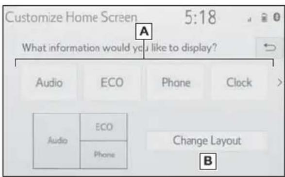
text_image
Customize Home Screen 5:18 What information would you like to display? Audio ECO Phone Clock > Audio ECO Phone Change Layout BA Select to change the display information and area on the home screen.
B Select to change the home screen layout.
Entering letters and numbers/list screen operation
Entering letters and numbers
When searching by a name or entering data, letters and numbers can be entered via the screen.
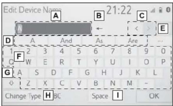
text_image
Edit Device Name 21:22 A B C D A And As Are ... 1 2 3 4 5 6 7 8 9 0 F W E R T Y U I O P G A S D F G H J K L Z X C V B N M - Change Type H BC Space I OKA Text field. Entered character(s) will be displayed.
B Select to erase one character.
Select and hold to continue erasing characters.
C Select to move the cursor.
D Select to choose predictive text candidate for entered text. (→P.398)
E Select to display a list of predictive text candidates when there is more than one. (→P.398)
F Select to enter desired characters.
G Select to enter characters in lower case or in upper case.
H Select to change character types. (→P.398)
I Select to make a space on cursor.
● Keyboard layout can be changed.
(→P.426)
Changing character type
1 Select "Change Type".
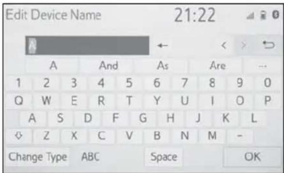
text_image
Edit Device Name 21:22 A And As Are ... 1 2 3 4 5 6 7 8 9 0 Q W E R T Y U I O P A S D F G H J K L ◇ Z X C V B N M - Change Type ABC Space OK2 Select the desired character.
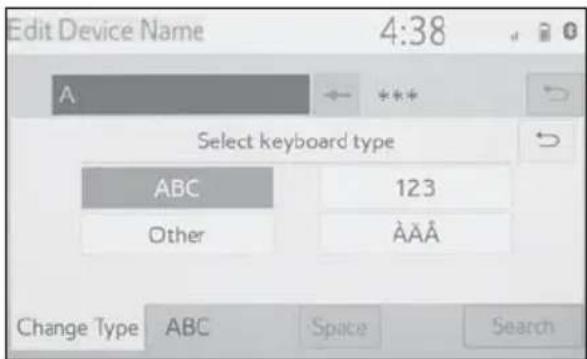
text_image
Edit Device Name 4:38 A ← *** Select keyboard type ABC 123 Other AÃÃ Change Type ABC Space Search● Depending on the screen being displayed, it may not be possible to change keyboard characters.
Displaying predictive text candidates
When text is input, the system predicts the text that may complete the currently unconfirmed text and displays predictive replacement candidates that match the beginning of the text.
1 Input text.
2 Select the desired candidate.
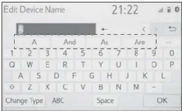
text_image
Edit Device Name 21:22 A And As Are ... 1 2 3 4 5 6 7 8 9 0 Q W E R T Y U I O P A S D F G H J K L Z X C V B N M - Change Type ABC Space OK- To select a candidate that is not displayed, select •,• and then select the desired predictive replacement candidate.
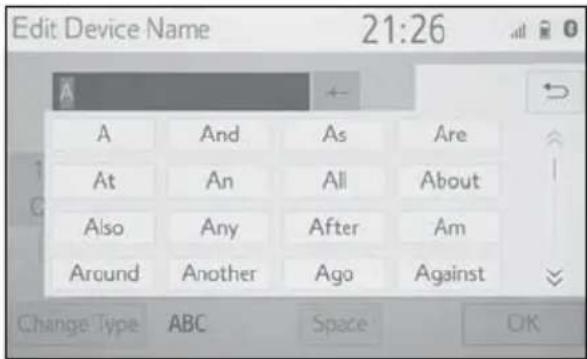
text_image
Edit Device Name 21:26 A And As Are At An All About Also Any After Am Around Another Ago Against Change Type ABC Space OKList screen
The list screen may be dis- played after entering characters. When a list is displayed, use the appropriate screen button to scroll through the list.
Scrolling list screen
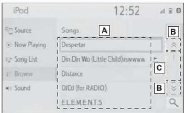
text_image
iPod 12:52 Source Now Playing Song List Browse Sound Songs A B Despertar Din Din Wo (Little Child)sswwwww Distance DJDJ (for RADIO) E.LE.M.E.N.T.S C BA To scroll up/down the list, flick the list up/down.
B Select to skip to the next or previous page. Select and hold or to scroll through the displayed list.
C Indicates the position of the displayed entries in the entire list.
To scroll up/down pages, drag the bar.
- If appears to the right of an item name, the complete name is too long to display.
- Select to scroll to the end of the name.
- Select to move to the beginning of the name.
Searching a list
Items are displayed in the list with the most similar results of the search at the top.
1 Select


text_image
8:18 History Favorites Contacts Keypad Select Device Message2 Input text.
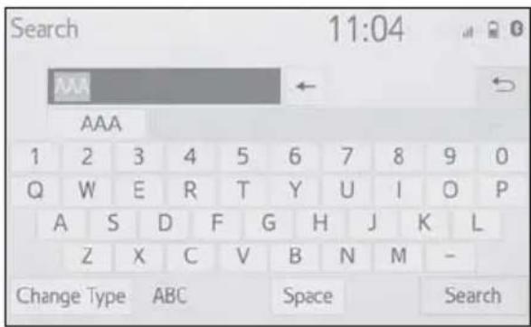
text_image
Search 11:04 AAA AAA 1 2 3 4 5 6 7 8 9 0 Q W E R T Y U I O P A S D F G H J K L Z X C V B N M - Change Type ABC Space Search3 Select "Search".
4 The list is displayed.
Screen adjustment
The contrast and brightness of the screen display and the image of the camera display can be adjusted. The screen can also be turned off, and/or changed to either day or night mode.
(For information regarding audio/visual screen adjustment: →P.435)
Displaying the screen adjustment screen
1 Press the "MENU" button.
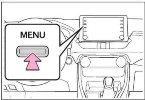
text_image
MENU2 Select "Display".
3 Select the desired items to be set.
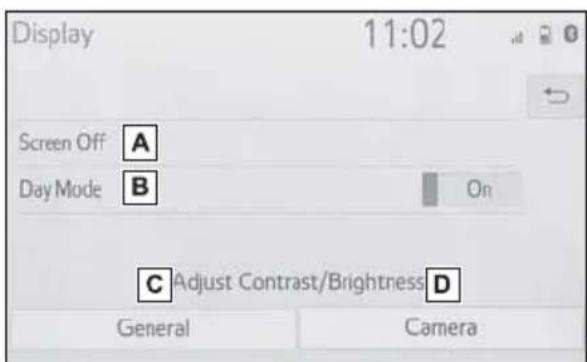
text_image
Display 11:02 Screen Off A Day Mode B On C Adjust Contrast/Brightness D General CameraA Select to turn the screen off. To turn it on, press any but-
ton.
B Select to turn day mode on/off. (→P.400)
C Select to adjust the screen display. (→P.400)
D Select to adjust the camera display.
- When the screen is viewed through polarized sunglasses, a rainbow pattern may appear on the screen due to optical characteristics of the screen. If this is disturbing, please operate the screen without polarized sunglasses.
Changing between day and night mode
Depending on the position of the headlight switch, the screen changes to day or night mode. This feature is available when the headlight is switched on.
1 Select "Day Mode".
- If the screen is set to day mode with the headlight switch turned on, this condition is memorized even with the hybrid system turned off.
Adjusting the contrast/brightness
The contrast and brightness of the screen can be adjusted according to the brightness of your surroundings.
1 Select "General" or "Camera".
2 Select the desired item.
- “Display (General)” screen only: Select “<” or “>” to select the desired display.
- "Contrast"
“+”: Select to strengthen the contrast of the screen.
“-”: Select to weaken the contrast of the screen. - "Brightness"
“+”: Select to brighten the screen.
“-”: Select to darken the screen.
Linking multi-information display and the system
The following functions of the system are linked with the multi-information display in the instrument cluster:
- Audio
- Phone*
etc.
These functions can be operated using meter control switches on the steering wheel. (→P.103)
*: When an Apple CarPlay connection is established, this function will be unavailable.
Registering/Connecting a Bluetooth® device
To use the hands-free system, it is necessary to register a Bluetooth ^® phone with the system.
Once the phone has been registered, it is possible to use the hands-free system.
This operation cannot be performed while driving.
When an Apple CarPlay connection is established, Bluetooth® functions of the system will become unavailable and any connected Bluetooth® devices will be disconnected.
When connecting to Android Auto, a Bluetooth® connection will be made automatically.
When an Android Auto connection is established, some Bluetooth® functions other than hands-free system cannot be used.
Registering a Bluetooth® phone for the first time
■Registering from the sys-tem
1 Turn the Bluetooth ^® connection setting of your cellular phone on.
- This function is not available when Bluetooth® connection setting of your cellular phone is set to off.
2 Press the "MENU" button.

text_image
MENU3 Select "Phone".
● Operations up to this point can also be performed by pressing the "PHONE" button on the instrument panel.
4 Select "Yes" to register a phone.
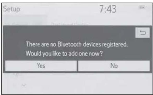
text_image
Setup 7:43 There are no Bluetooth devices registered. Would you like to add one now? Yes No5 Select the desired Bluetooth® device.
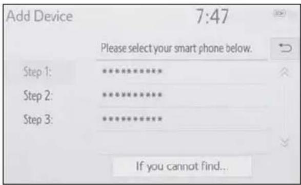
text_image
Add Device 7:47 Please select your smart phone below. Step 1: ********** Step 2: ********** Step 3: ********** If you cannot find...- If the desired Bluetooth® phone is not on the list, select "If you cannot find..." and follow the guidance on the screen. (→P.404)
6 Register the Bluetooth ^® device using your Bluetooth ^® device.
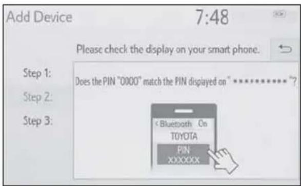
text_image
Add Device 7:48 Please check the display on your smart phone. Step 1: Does the PIN "0000" match the PIN displayed on "**********" Step 2: Step 3:text_image
Add Device 7:48 Connecting... Step 1: Step 2: Step 3.text_image
Add Device 7:49 Connected Step 1: Step 2: Step 3:■Registering from phone
1 Select "If you cannot find...". text_image
Add Device 7:47 Please select your smart phone below. Step 1: ********** Step 2: ********** Step 3: ********** If you cannot find...text_image
Add Device 7:47 Please perform the following procedure or complete registration from the phone: 1. Check the Bluetooth setting on your phone. 2. Check that your phone is visible to other Bluetooth devices. 3. Charge your phone's battery if it is low. Retry Register from Phone If you cannot find...text_image
Add Device 7:47 Please stay on this screen during registration... Step 1: Make sure that Bluetooth on your device is turned ON. Step 2: Search for and select "***************" on your device. Step 3: Confirm the Bluetooth PIN "****" on your device. CancelRegistering a Bluetooth® audio player for the first time
To use the Bluetooth ^® audio, it is necessary to register an audio player with the system. Once the player has been registered, it is possible to use the Bluetooth ^® audio. This operation cannot be performed while driving. For details about registering a Bluetooth® device: →P.409 1 Turn the Bluetooth ^® connection setting of your audio player on. - This function is not available when the Bluetooth® connection setting of your audio player is set to off. 2 Press the "AUDIO" button. text_image
AUDIOProfiles
This system supports the following services.Bluetooth® Core Specification
● Ver. 2.0 or higher (Recommended: Ver. 4.2 or higher)Profiles
● HFP (Hands Free Profile) Ver. 1.0 (Recommended: Ver. 1.7) - This is a profile to allow hands-free phone calls using a cellular phone. It has outgoing and incoming call functions. - OPP (Object Push Profile) Ver. 1.1 (Recommended: Ver. 1.2) • This is a profile to transfer contacts data. ● PBAP (Phone Book Access Profile) Ver. 1.0 (Recommended: Ver. 1.2) • This is a profile to transfer phone-book data. ● MAP (Message Access Profile) Ver. 1.0 (Recommended: Ver. 1.2) • This is a profile to use phone message functions. ● SPP (Serial Port Profile) Recommended: Ver. 1.2 • This is a profile to use the Toyota audio multimedia function. ● A2DP (Advanced Audio Distribution Profile) Ver. 1.0 (Recommended: Ver. 1.3) - This is a profile to transmit stereo audio or high quality sound to the audio/visual system. ● AVRCP (Audio/Video Remote Control Profile) Ver. 1.0 (Recommended: Ver. 1.6) • This is a profile to allow remote control the A/V equipment. - This system is not guaranteed to operate with all Bluetooth ^ devices. - If your cellular phone does not support HFP, registering the Bluetooth® phone or using OPP, PBAP, MAP or SPP profiles individually will not be possible. - If the connected Bluetooth ^ device version is older than recommended or incompatible, the Bluetooth ^ device function may not work properly. - Refer to http://www.toyota.com/audio-multimedia in the United States, http://www.toyota.ca/connected in Canada, and http://www.toyotapr.com/audio-multimedia in Puerto Rico, to find approved Bluetooth® phones for this system. ●Certification Bluetooth®
Bluetooth is a registered trademark of Bluetooth SIG, Inc.Setting Bluetooth® details
When an Apple CarPlay connection is established, this function will be unavailable.\* When an Android Auto connection is established, some functions will be unavailable.\* \*: This function is not made available in some countries or areas.Displaying the Bluetooth® setup screen
1 Press the "MENU" button. text_image
MENUtext_image
Setup 7:53 General Registered Device Bluetooth Add New Device Audio Remove Device Phone Detailed Settings VoiceBluetooth® setup screen
text_image
Setup 7:53 General Registered Device A Bluetooth Add New Device B Audio Remove Device C Phone Detailed Settings D VoiceConnecting a Bluetooth ^® device
Up to 5 Bluetooth ^® devices (Phones (HFP) and audio players (AVP)) can be registered. If more than 1 Bluetooth ^® device has been registered, select which device to connect to. 1 Display the Bluetooth ^® settings screen. (→P.406) 2 Select "Registered Device". 3 Select the device to be connected. text_image
Registered Device 15:59 iPhone Android phone Add Preferred Device Settings Removetext_image
8:05 Connect ********* Disconnect ********* Disconnect as a Phone Connect as an Audio Player Device Info■Auto connection mode
To turn auto connection mode on, set "Bluetooth Power" to on. (→P.411) Leave the Bluetooth® device in a location where the connection can be established. - When the power switch is in ACC or ON, the system searches for a nearby registered device. - The system will connect with the registered device that was last connected, if it is nearby. When automatic connection priority is set to on and there is more than one registered Bluetooth® phone available, the system will automatically connect to the Bluetooth® phone with the highest priority. ( P.411)■Connecting manually
When the auto connection has failed or "Bluetooth Power" is turned off, it is necessary to connect the Bluetooth® device manually. 1 Display the Bluetooth ^® settings screen. (→P.406) 2 Follow the steps in "Connecting a Bluetooth® device" from step 2. (→P.407)■Reconnecting the Bluetooth® phone
If a Bluetooth ^® phone is disconnected due to poor reception from the Bluetooth ^® network when the power switch is in ACC or ON, the system automatically reconnects the Bluetooth ^® phone.Registering a Bluetooth ^® device
Up to 5 Bluetooth ^® devices can be registered. Bluetooth ^® compatible phones (HFP) and audio players (AVP) can be registered simultaneously. This operation cannot be performed while driving. 1 Display the Bluetooth ^® settings screen. (→P.406) 2 Select "Add New Device". When another Bluetooth® device is connected \- To disconnect the Bluetooth® device, select "Yes". When 5 Bluetooth ^® devices have already been registered \- A registered device needs to be replaced. Select "Yes", and select the device to be replaced. 3 Follow the steps in "Registering a Bluetooth® phone for the first time" from step 5. (→P.402)Deleting a Bluetooth ^® device
This operation cannot be performed while driving. 1 Display the Bluetooth ^® settings screen. (→P.406) 2 Select "Remove Device". 3 Select the desired device. text_image
Remove Device 8:03 Select a device to remove: ****** ***************Editing the Bluetooth® device information
The Bluetooth® device's information can be displayed on the screen. The displayed information can be edited. This operation cannot be performed while driving. 1 Display the Bluetooth ^® settings screen. (→P.406) 2 Select "Registered Device". 3 Select the desired device to be edited. 4 Select "Device Info". text_image
8:05 Connect ***** Disconnect ***** Disconnect as a Phone Connect as an Audio Player Device Infotext_image
Device Information 8:05 Device Name ********* > A Connect Audio Player From Vehicle √ B Bluetooth Address ********** Phone Number ********** Supported Profiles: Default Ftext_image
Device Information 8:06 Connect Audio Player From Vehicle Bluetooth Address ****** Phone Number ****** Supported Profiles: HFP, OPP, PBAP, A2DP, AVRCP, MAP Default FChanging a device name
1 Select "Device Name". 2 Enter the name and select "OK". - Even if the device name is changed, the name registered in your Bluetooth® device does not change.Setting audio player connection method
1 Select "Connect Audio Player From". 2 Select the desired connection method. text_image
Device Information 8:06 Device Name ******** > Connect Audio Player From ● Vehicle ● Device Bluetooth Address ********** Default"Detailed Settings" screen
The Bluetooth ^® settings can be confirmed and changed. 1 Display the Bluetooth ^® settings screen. (→P.406) 2 Select "Detailed Settings". 3 Select the desired item to be set. text_image
Detailed Settings 8:07 Bluetooth Power On A Preferred Device Settings B System Information C Default DChanging "Bluetooth Power"
1 Select "Bluetooth Power". When "Bluetooth Power" is on: The Bluetooth® device is automatically connected when the power switch is in ACC or ON. When "Bluetooth Power" is off: The Bluetooth® device is disconnected, and the system will not connect to it next time. ●While driving, the auto connection state can be changed from off to on, but cannot be changed from on to off.Setting automatic connection priority
The automatic connection priority of the registered Bluetooth ^® devices can be changed. 1 Select "Preferred Device Settings". 2 Select the desired item to be set. text_image
Preferred Device Settings 8:07 Preferred Device Settings On A > Preferred Phones > B Preferred Audio Players > C Default D■Changing Bluetooth ^® device automatic connection priority
1 Select "Preferred Phones" or "Preferred Audio Players". 2 Select the desired Bluetooth® device and select "Move Up" or "Move Down" to change the preferred order. text_image
Preferred Phones 8:08 Change the order of automatic connection. 1 ********** 2 ********** Move Up Move DownEditing the system information
1 Select "System Information". 2 Select the desired item to be set. text_image
System Information 8:12 System Name ******** > A System PIN Code 0000 > B Bluetooth Address ******** C Display Phone Status Off D Display Audio Player Status Off E Default Gtext_image
System Information 8:12 Bluetooth Address Display Phone Status Off Display Audio Player Status Off Supported Profiles: HFP, SPP, OPP, PBAP, A2DP, AVRCP, MAP Default G■Editing the system name
1 Select "System Name". 2 Enter a name and select "OK".■ Editing the PIN code
1 Select "System PIN Code". 2 Enter a PIN code and select "OK".Wi-Fi® Hotspot\*
\*: Vehicles equipped with DCM only. This function is not made available in some countries or areas.By connecting a device to the vehicle via Wi-Fi ^® , it can access the internet through the DCM.
\- To use this function, a Wi-Fi® Hotspot service subscription from AT&T is required. Connect your device to the in-vehicle access point (see instructions below), or contact your Toyota dealer for details.Connecting a device to the in-vehicle access point
Searching for and connecting a device to the vehicle access point
1 Enable the Wi-Fi ^® Hotspot function. (→P.415) 2 Disable the "Hide Access Point" function. (→P.415) 3 Search for the vehicle access point using the device you wish to connect. - For details about operating the device, refer to the documentation which came with it. 4 Operate the device to connect it to the vehicle access point. \- To check the vehicle access point password, check "Password". (→P.415) \- Hints for connecting to the vehicle via Wi-Fi® can be displayed. (→P.415)Connecting a device to the in-vehicle access point using the access point name (SSID)
1 Enable the Wi-Fi ^® Hotspot function. (→P.415) 2 Enable the "Hide Access Point" function. (→P.415) 3 Enter the access point name (SSID) into the device you wish to connect and connect it. - To check the vehicle access point password, check "Password". (→P.415) - The security settings on the device must be the same as that displayed for “Security”. (→P.415) - For details about operating the device, refer to the documentation which came with it.Changing the Wi-Fi® settings
1 Press the "MENU" button. text_image
MENUtext_image
Setup 1:13 Wi-Fi Hotspot On A Now discoverable. You can look for the wireless access point" ********** from your mobile devices. Password > How to Connect Ctext_image
Setup 1:13 Password How to Connect Hi- Fi Hide Access Point Off D Security WPA2 (AES) E Access Point Name F Channel GEnabling/disabling the Wi-Fi® Hotspot function
When the Wi-Fi ^® Hotspot function is enabled, the system checks for a valid Hotspot service subscription. If a Hotspot service subscription has not been started, connect your device to the in-vehicle access point to start your subscription. A trial subscription may be available. Contact your Toyota dealer for details about the Toyota Apps.Checking/changing the password
1 Select "Password". 2 Check that the following screen is displayed. text_image
Password 1:13 Current password: ************ Show Characters Off B Change Password > CChanging the password
1 Select "Change Password". 2 Enter the desired password and select "OK". \- When setting/changing a password, observe the following guidelines to help prevent the password from being cracked by a third party: \- Use an 8-character or longer password consisting of letters and numbers. (Non-ASCII characters will not be recognized by the system.) - Change the password regularly. - If you write the password down, do not leave it somewhere where it would be visible. - Do not use the same password for vehicle Wi-Fi® Hotspot as other accounts already protected by a password. - Avoid using easy to identify words, such as your vehicle's model name or license plate number, simple dictionary words, or words with simple obfuscation, such as c@t (for cat), as your password.Changing the security protocol
1 Select "Security". 2 Select the desired security protocol.Changing the access point name (SSID)
1 Select "Access Point Name". 2 Enter the desired access point name (SSID) and select "OK".Selecting a Wi-Fi ^® connection channel
1 Select "Channel". 2 Check that the following screen is displayed. text_image
Channel 1:13 Select Channel Auto A Channel Number > BChanging the channel
1 Set "Select Channel" to "Manual". 2 Select "Channel Number". 3 Enter the desired channel number and select "OK". ● Channels 1 through 11 can be selected.Wi-Fi ^® function operating hints
- If a connected device is taken out of the Wi-Fi ^ connection area, the connection will be severed. - If the vehicle is driven out of the cellular communication coverage area, connecting to the internet via the Wi-Fi® Hotspot will not be possible. - If a Bluetooth ^ device is used while a device is connected using the Wi-Fi ^® Hotspot function, the communication speed may decrease. \- If the vehicle is near a radio antenna, radio station or other source of strong radio waves and electrical noise, communication may be slow or impossible. WARNING
- Use Wi-Fi ^ devices only when safe and legal to do so. - Your audio unit is fitted with Wi-Fi® antennas. People with implantable cardiac pacemakers, cardiac resynchronization therapy-pacemakers or implantable cardioverter defibrillators should maintain a reasonable distance between themselves and the Wi-Fi® antennas. The radio waves may affect the operation of such devices. Before using Wi-Fi ^® devices, users of any electrical medical device other than implantable cardiac pacemakers, cardiac resynchronization therapy-pacemakers or implantable cardioverter defibrillators should consult the manufacturer of the device for information about its operation under the influence of radio waves. Radio waves could have unexpected effects on the operation of such medical devices.Conditions displayed with Wi-Fi® icon
The condition of Wi-Fi ^® connection appears on the right upper side of the screen. (→P.390)Specifications
● Communication standards IEEE 802.11b IEEE 802.11g IEEE 802.11n (2.4GHz) ● Security WPA™ WPA2™ \- WPA ^TM and WPA2 ^TM are trademarks of Wi-Fi Alliance ^ .Apple Car-Play®/Android Auto™\*
\*: This function is not made available in some countries or areas.Apple CarPlay/Android Auto allows some applications, such as Map, Phone, and Music, to be used on the system.
When an Apple Car-Play/Android Auto connection is established, Apple CarPlay/Android Auto compatible applications will be displayed on the system display. \- Compatible device Apple iPhone (iOS Ver. 9.3 or later) that supports Apple Car-Play.\* For details, refer to https://www.apple.com/ios/carplay/. Android™ devices with Android OS ver 5.0 or higher which support Android Auto and have the Android Auto application installed.\* For details, refer to https://www.android.com/auto/ \*: Some devices may not operate with this system.Establishing an Apple CarPlay connection
1 Enable Siri on the device to be connected. 2 Connect the device to the USB port. ( P.434) 3 Select "Always Enable" or "Enable Once". - If “Do not enable” is selected, an Apple CarPlay connection will not be established. In this case, the device can be operated as a normal Apple device, such as an iPod. Apple CarPlay will remain off until “Apple CarPlay” of “Projection Settings” on the general settings screen is turned on. (→P.426) - Depending on the device connected, it may take approximately 3 to 6 seconds before the system returns to previous screen. - The screen may change to step 6 depending on the system. 4 Press the "MENU" button. text_image
MENUtext_image
Menu 10:26 Audio Phone Apps Apple CarPlay Info Setup Displaytext_image
11:26 0000 4G A Now Playing TOYOTA B CEstablishing an Android Auto connection
1 Check that the Android Auto application is installed to the device to be connected. 2 Connect the device to the USB port. (→P.434) 3 Select "On" to enable the function. - “Off”: Select to not enable Android Auto. Android Auto will remain off until “Android Auto” of “Projection Settings” on the general settings screen is turned on. (→P.426) - Depending on the device connected, it may take approximately 3 to 6 seconds before the system returns to previous screen. ● The screen may change to step 6 depending on the system. 4 Press the "MENU" button. text_image
MENUtext_image
Menu 10:27 Audio Phone Apps Android Auto Info Setup DisplayCertification
text_image
Works with Apple CarPlayWARNING
\- Do not connect iPhone or operate the controls while driving. NOTICE
\- Do not leave your smartphone in the vehicle. In particular, high temperatures inside the vehicle may damage the smartphone. \- Do not push down on or apply unnecessary pressure to the smartphone while it is connected as this may damage the smartphone or its terminal. \- Do not insert foreign objects into the port as this may damage the smartphone or its terminal.Troubleshooting
If you are experiencing difficulties with Apple CarPlay/Android Auto, check the following table.| Symptom Solution | |
| An Apple Car-Play/Android Auto connection cannot be established. | Check if the device supports Apple Car-Play/Android Auto.Check if Apple CarPlay/Android Auto is enabled on the connected device.Check that the Android Auto application is installed to the device to be connected.For details, refer tohttps://www.apple.com/ios/carplay/,https://www.android.com/auto/.For available countries or areas for Apple Car-Play, refer tohttps://www.apple.com/ios/feature-availability/# apple carplay. |
| Check if “Apple CarPlay”/“Android Auto” of “Projection Settings” on the general settings screen is set to on. (→P.426) | |
| Check if the USB cable being used is securely connected to the device and USB port.Try connecting the smartphone directly to the USB port in the vehicle, without using the hub.For Apple CarPlay: Check if the Lightning cable being used is certified by Apple and check if Siri is enabled. | |
| After checking all of the above, try to establish an Apple CarPlay/Android Auto connection.(→P.419) | |
| When an Apple Car-Play/Android Auto connection is established and a video is being played, the video is not displayed, but audio is output through the system. | As the system is not designed to play video through Apple CarPlay/Android Auto, this is not a malfunction. |
| Although an Apple Car-Play/Android Auto connection is established, audio is not output through the system. | The system may muted or the volume may be low. Increase the system volume. |
| The Apple Car-Play/Android Auto screen has flickers and/or audio from Apple Car-Play/Android Auto has noise. | Check if the USB cable being used to connect the device to the system is damaged.To check if the USB cable is damaged internally, connect the device to another system, such as a PC, and check if the device is recognized by the connected system. (The device should begin charging when connected.) |
| After checking all of the above, try to establish an Apple CarPlay/Android Auto connection.(→P.419) | |
| The map display of the Apple CarPlay Maps app cannot be enlarged or contracted with pinch multi-touch gestures. | As the Apple CarPlay Maps app is not compatible with pinch multi-touch gestures, this is not a malfunction. |
| During Apple CarPlay music application (Apple Music, Spotify, etc.) play-back, if the iPhone is operated to start and play audio from an application that is not compatible with Apple CarPlay* and the onboard device volume is changed, the audio of the incompatible application stops and the system resumes playback of the original music application. | This operation is performed according to the specification of the onboard device, this is not a malfunction. |
| After interrupt audio (such as navigation route guidance) is played from an application that is not compatible with Apple CarPlay while the onboard device is playing audio (FM/AM, etc.), the system does not resume playback of the original audio (FM/AM, etc.). | This operation is performed according to the specification of the onboard device, this is not a malfunction. Manually change the audio source by yourself. Or, do not use applications that are not compatible with Apple CarPlay.* Due to some navigation applications are compatible from iOS 12, update to the latest iOS and application versions. |
| When using Apple Car-Play, route guidance arrows and turn by turn navigation are not displayed on the multi-information display and system display. When using Android Auto, turn by turn navigation is not displayed on the multi-information display and system display. | This is not a malfunction as display of these items is not possible with this function. |
| When using Android Auto, hands-free call audio cannot be heard from the vehicle's speakers. | Disconnect the phone from the USB cable and check if hands-free call audio can be heard using the hands-free system. |
| Connect the phone to the system using Android Auto, turn up the volume on the system and check if hands-free call audio can be heard. Check if other sounds can be heard from the vehicle's speakers. |