
CS 6340 FH - Uncategorized SHURE - Free user manual and instructions
Find the device manual for free CS 6340 FH SHURE in PDF.


| Product Type | Flush-Mounted Channel Selector |
| Model | CS 6340 FH (Horizontal Version) |
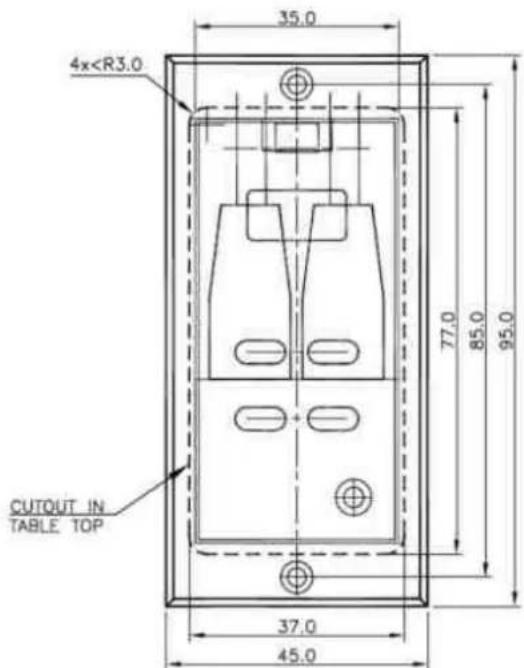
| Dimensions (W x H x D) | 95 x 45 x 40 mm |
| Power Supply | 24-48 V DC via DCS-LAN |
| Power Consumption | 0.5 W |
| Frequency Response | 125-15,000 Hz |
| Signal-to-Noise Ratio | >85 dBA |
| Total Harmonic Distortion | <0.1% |
| Headphone Output Load | 16-2,000 ohms |
| Max. Output Level | 1.2 V RMS |
| Channel Range | 0-31 (or 1-32 via system setting) |
| Channel Selection | Up/Down buttons with wrap-around option |
| Volume Control | Up/Down buttons with adjustable step size |
| Display | LCD with backlight (5 sec. on button press) |
| Audio Output Connectors | Front: 3.5 mm mini-jack; Rear: 2-pin Molex (professional use only) |
| Network Connectors | 2 x RJ45 for DCS-LAN (Cat5e FTP/STP) |
| Compliance | FCC Part 15B, E2 (Commercial & Light Industrial) |
| Operating Temperature | 5°C to 40°C (35-80% humidity) |
| Storage Temperature | -20°C to 60°C (10-80% humidity) |
| Included Accessories | User manual |
Frequently Asked Questions - CS 6340 FH SHURE
User questions about CS 6340 FH SHURE
0 question about this device. Answer the ones you know or ask your own.
Ask a new question about this device
Download the instructions for your Uncategorized in PDF format for free! Find your manual CS 6340 FH - SHURE and take your electronic device back in hand. On this page are published all the documents necessary for the use of your device. CS 6340 FH by SHURE.
USER MANUAL CS 6340 FH SHURE
Conferencing and Discussion Systems
CS 6340 F Channel Selectors
USER GUIDE
natural_image
Two black industrial control panel devices with buttons and indicators, no visible text or symbols on the surfaces.Table of Contents
Table of Contents ...... 2
Important 3
Installation precautions .... 3
Compliance 3
Information to the user 3
Cleaning 4
Repacking 4
Warranty 4
Your DCS 6000 Conference System ...... 5
The DCS 6000 system .... 5
System components 6
Central equipment etc. 6
Interpreter equipment 6
Conference units and Ch. selectors ...... 6
Accessories 6
Operating instructions 7
CS 6340 Channel Selector .... 7
General description 7
Features 7
User Controls, indications & connectors ... 7
Normal Operation.... 7
Startup / Error conditions 8
System Setup 9
General guidelines 9
Typical schematics 9
Technical Specifications 10
Connection Details ...... 11
Accessories 11
Important
Installation precautions
Do not install the unit in a location near heat sources such as radiators or air ducts, or in a place exposed to direct sunlight, excessive dust or humidity, mechanical vibration or shock.
Compliance
The equipment is intended to be used in professional audio applications.
Note: This device is not intended to be connected directly to a public internet network.
EMC conformance to Environment E2: Commercial and Light Industrial.
Testing is based on the use of supplied and recommended cable types.
The use of other than shielded (screened) cable types may degrade EMC performance.
Changes or modifications not expressly approved by Shure Incorporated could void your authority to operate this equipment.
Authorized under the verification provision of FCC Part 15B.
Please follow your regional recycling scheme for batteries, packaging, and electronic waste.
Information to the user
This equipment has been tested and found to comply with the limits for a Class B digital device,
To avoid moisture condensations do not install the units where the temperature may rise rapidly.
To avoid moisture condensations do not install the unit where the temperature may rise rapidly.
pursuant to Part 15 of the FCC Rules. These limits are designed to provide reasonable protection against harmful interference in a residential installation.
This equipment generates uses and can radiate radio frequency energy and, if not installed and used in accordance with the instructions, may cause harmful interference to radio communications. However, there is no guarantee that interference will not occur in a particular installation. If this equipment does cause harmful interference to radio or television reception, which can be determined by turning the equipment off and on, the user is encouraged to try to correct the interference by one or more of the following measures:
• Reorient or relocate the receiving antenna.
- Increase the separation between the equipment and the receiver.
- Connect the equipment to an outlet on a circuit different from that to which the
• receiver is connected.
- Consult the dealer or an experienced radio/TV technician for help.
Cleaning
To keep the cabinet in its original condition, periodically clean it with a soft cloth. Stubborn stains may be removed with a cloth lightly
Repacking
Save the original shipping cardboard box and packing material; they will become handy if you ever have to ship the unit. For maximum protection,
Warranty
The individual units in the DCS 6000 system are minimum covered by 24 months warranty against defects in materials or workmanship.
dampened with a mild detergent solution. Never use organic solvents such as thinners or abrasive cleaners since these will damage the cabinet.
re-pack the unit as originally packed from the factory.
Your DCS 6000 Conference System
The DCS 6000 system
DCS 6000 Digital Conference System is a system to be used at meetings, where a number of people are addressing the 'Floor' in a structured manor. The audio from the Conference units can be heard in the built in loudspeakers in the units.
The system does also allow for simultaneous interpretation for international conferences where multiple languages are used.
To enable all participants to understand the proceedings, interpreters can simultaneously translate the speaker's language as required. These interpretations are distributed through the connected Conference units and delegates can select the language of their choice and listen to it through headphones.
DCS 6000 Digital Conference System comprises of one CU 61xx Central Unit and a number of Conference Units, Gooseneck Microphones and other accessories depending on the system configuration.
The DCS 6000 system has the following main features:
- Fully digital
• Excellent sound quality - "State of the Art" fully digital integrated interpretation, discussion and voting system offering interpretation, language distribution, conference microphone and voting facilities with attendance check with Chip Card ^TM
- Digital transmission of audio from/to the Conference unit to/from the central unit using a unique digital DATA and AUDIO bus named DCS-LAN
- Control of up to 3800 conference units. This number does not include Channel Selectors, Repeaters etc. In practical use there are no limits for the number of Channel Selectors in a system
- Delegate and Interpreter units are powered and controlled by the CU 61xx Central Unit, which drives up to app. 50 units with the PS CU power supply
-
EX 6010 Extension Unit or PS 6001 DCS-LAN Power Kit is available if more units are required
-
Delayed switching on of power to the two DCS-LAN chains, to minimize the total 'in-rush' current on the Mains supply
- Designed for 31 interpretation channels and 8 open microphones
• Audio scrambling of the audio to avoid eavesdropping - Designed in a standard 1HE 19" cabinet
- TCP/IP connection on CU 61xx for external operation of the system using a PC or control system such as AMX ® or Crestron ®
- Functionality on the CU 61xx depends on the Feature License uploaded into the unit
- Firmware in Delegate units, Interpreter Units, Central Units etc. is upgradeable
- Operated either stand alone or from a PC using the CU browser or using SW 6000 software
- Added functionality and comprehensive features provided by SW 6000 software package running on PC
The SW 6000 is an optional software package, which expands the functionality of the DCS 6000 system. The software runs on standard computer technology (Standard PC with Windows 7, Server 2008 etc.).
Main features of the SW 6000 are:
• Microphone management
• Mimic panel operation
• Interpretation management
• Voting management
- Message handling
- Agenda handling
• Data stored on SQL data base
- Web service interface available for easy links to external applications
• Multi language user interfaces
• Supports different User types with different priorities, user interfaces and control possibilities
System components
Central equipment etc.
CU 6105 Central Unit
CU 6110 Central Unit
EX 6010 Extension Unit
PS 6001 DCS-LAN Power Kit consisting of one PS CU and one PI 6000
PS CU Power Supply
PI 6000 DCS-LAN Power Inserter
RC 6000 Redundancy Controller
AO 6004 Audio Output Unit
AO 6008 Audio Output Unit
RP 6004 Repeater for four chains
JB 6104 Junction Box with 4 outputs
Interpreter equipment
IS 6132 P Interpreter Unit
LS 6132 P Interpreter Loudspeaker
Conference units and Ch. selectors
DC 6990 P Conference Unit (portable) with touch screen with two built-in channel selector, Chip-card and 5 voting buttons, configurable as Delegate, Dual Delegate or Chairman.
DC 6120 P Conference Unit (portable)
DC 6190 P Conference Unit (portable) with two built-in channel selectors
DM 6680 P Conference Unit (portable) with voting
CM/DM 6080 F Conference Unit (flush mounted) with built-in channel selectors
DM 6620 F Conference Unit (flush mounted) with, Chip-card and 5 voting buttons
CM/DM 6680 F Conference Unit (flush mounted) with one built-in channel selector, Chip-card and 5 voting buttons
MU 6040 C/D Microphone Unit for use with FD/FC front plate with Loudspeaker, Microphone and Buttons. Available in Delegate (D) and Chairman (C) version
MU 6042 D Dual Microphone Unit for use with FD/FC front plate with Loudspeaker, Microphone and two delegate Buttons
DV 6501 F Voting Unit
AM 6040 Ambient Microphone Unit
CS 6340 FV/FH Channel Selector (flush mounted)
Accessories
In addition to the unit a number of accessories are available like:
- Storage Boxes
• GM 6523 Gooseneck Microphone, 40 cm
• GM 6524 Gooseneck Microphone, 50 cm
• GM 6525 Gooseneck Microphone, 63 cm
• DH 6021 Delegate Headphone
• DH 6223 Stethoscope Headphone
• DH 6225 Ear Clip Headphone
For detailed instruction in how to use the above units, please refer to the User Manuals for the relevant products.
Operating instructions
CS 6340 Channel Selector
General description
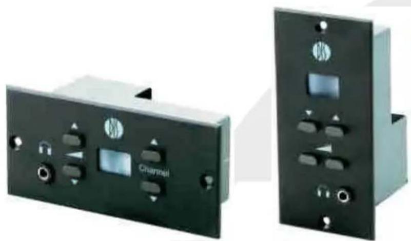
The CS 6340 channel selector is a very compact unit designed for flush mounted installation in tables, arm rests etc.
The standard units are designed with aluminium front plate.
Features
The main features of the CS 6340 Channel Selector are:
• Digital sound transmission
- Built in DSP
- Volume control
• Channel selection 0-31
• Light in LCD display
• Available in vertical, horizontal or customised version
- Connection for head phones either to a mini-jack at the front plate or to a miniature jack at the back for remote connection of the headphone.
- Many features can be set by system commands
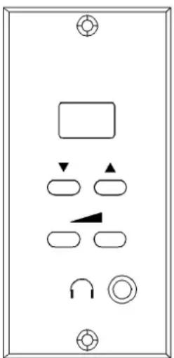
User Controls, indications & connectors Front plate layout (CS 6340FV)
natural_image
Pure electrical panel diagram without any text, numbers, or symbolsFront plate controls
The CS 6340 Channel Selector features the following controls and display:
Display
This display is used for information purposes and set-up purposes. This display has built in back light. When a button is depressed, the light is turned on for 5 sec.
Buttons (four)
The buttons are used for changing the channel setting or changing the volume setting. The buttons are also used for saving the settings or other control purposes.
Connectors
Headphone Connector (mini-jack)
A mini jack is located at the front for connecting a headphone for listening to the Floor language or one of the interpreted languages
Headphone Connector (Molex)
A 2 pin Molex jack is located at the back for connecting a headphone for listening to the Floor language or one of the interpreted languages.
This connector is intended for use, where the connection to the headphone is remotely from the front plate.
Important: This connector is intended for professional use only.
DCS-LAN connector
Two RJ45 sockets are located at the bottom of the unit for connecting to the other units on the DCS-LAN bus.
Normal Operation
Channel Selection
Channel selection is done using the channel up and channel down buttons. Channel numbers can be from 0 to 31.
The lowest channel (0) always carries floor audio and all other channels carry interpreted languages (or floor if no interpretation is currently performed on this channel). If fewer than 32 channels are in use only available channels will be selectable from the channel selector – the channels are always numbered
consecutively. Pressing the down button when the lowest channel number is displayed will cause the channel selection to wrap around to the highest available channel if the channel wrap parameter is set.
Holding the channel up or down button depressed will cause the channel numbers to scroll with a system defined start-up delay, and subsequent smaller delay between each change in channel position. These delays are set using system parameters.
On power-up the channel number will be either the system global power up setting or a locally saved power-up channel or floor channel if a locally saved channel number is outside the valid channel numbers.
Volume Control
Volume control is done using the volume up and volume down buttons. The number of volume levels and the step size in dB between successive levels is globally defined using system parameters – however setting the volume level to 0 turns the headphone/line output off.
When a volume button is depressed the channel display will be overridden with the current volume (this is indicated by the black dot in the upper left corner of the display) if the show volume global parameter is set. The display will continue to show the current volume level for a preset time interval before returning to displaying the channel information – this time interval is also set globally using a system parameter.
The audio can be attenuated on all interpreted channels, when no interpretation is performed and floor is present on the channel. This feature can be used when the channel selector is used in combination with an analogue microphone system to prevent feed-back from the channel selector to the microphone if the delegate is speaking and listening to the same channel. The attenuation in dB is set globally – however enabling or disabling this feature can be set individually on the channel selectors.
Storing local setup in FLASH
If enabled by the central unit the channel selectors may store the following local parameters in flash memory thus overriding the global system settings
• start-up volume level
- startup channel number
• attenuate floor audio on interpreted channel
To change the local setup in flash memory this must be globally enabled from the CU.
To set a new startup volume level use the volume up or down button to change to the wanted volume level and then depress both channel up and channel down buttons. After a short time period the display will show F1 – if the buttons are released while the display is showing F1 the display will change to FP to indicate that the new value is now programmed into flash memory. To clear the locally saved volume level position depress both channel up and channel down buttons until the display shows C1 then release the buttons – the display will then change to FC to indicate that the flash is cleared of this setting.
To set a new start up channel position use the channel up or down button to change to the wanted channel position and then depress both volume up and volume down buttons. After a short time period the display will show F2 – if the buttons are released while the display is showing F2 the display will change to FP to indicate that the new value is now programmed into flash memory. To clear the locally saved start up channel position depress both volume up and down buttons until the display shows C2 then release the buttons – the display will then change to FC to indicate that the flash is cleared of this setting.
To activate the attenuate floor audio on interpreted channel functionality of a unit depress the volume down and channel up buttons. After a short time period the display will show F4 – if the buttons are released while the display is showing F4 the display will change to FP indicating that the activation is now saved to flash. To deactivate the attenuate floor audio on interpreted channel functionality of a unit depress the volume down and channel up buttons until the display shows C4 then release the buttons – the display will then change to FC to indicate that the activation is now cleared from flash.
Startup / Error conditions
The following conditions in addition to the channel number are displayed:
• E0-E4, network error
• E5, network error or firmware mismatch
E9, reset
The channel selector will always show E1 shortly when powering up, then the display will change to show the channel number.
If any of the "E0-E5" messages is shown constantly, please check your cables and verify that the terminator plug is inserted in the last unit in the chain.
System Setup
General guidelines
Connect the CS 6340 Units at the DIS-LAN connectors to the various units using Cat 5e FTP or STP screened cables. Please observe the following guidelines:
• Maximum cable length in one chain when not using repeaters is 200 m.
• Maximum cable length in one chain when using repeaters is 650 m
- If the last unit in a chain is a CS 6032F the unit must have a DCS LAN Network Termination Plug inserted in one of the two DCS LAN Network connectors (RJ45 connectors).
Important: For more details about cabling and maximum number of units to connect to the DCS 6000 system please consult the 'User Manual CU 61xx'.
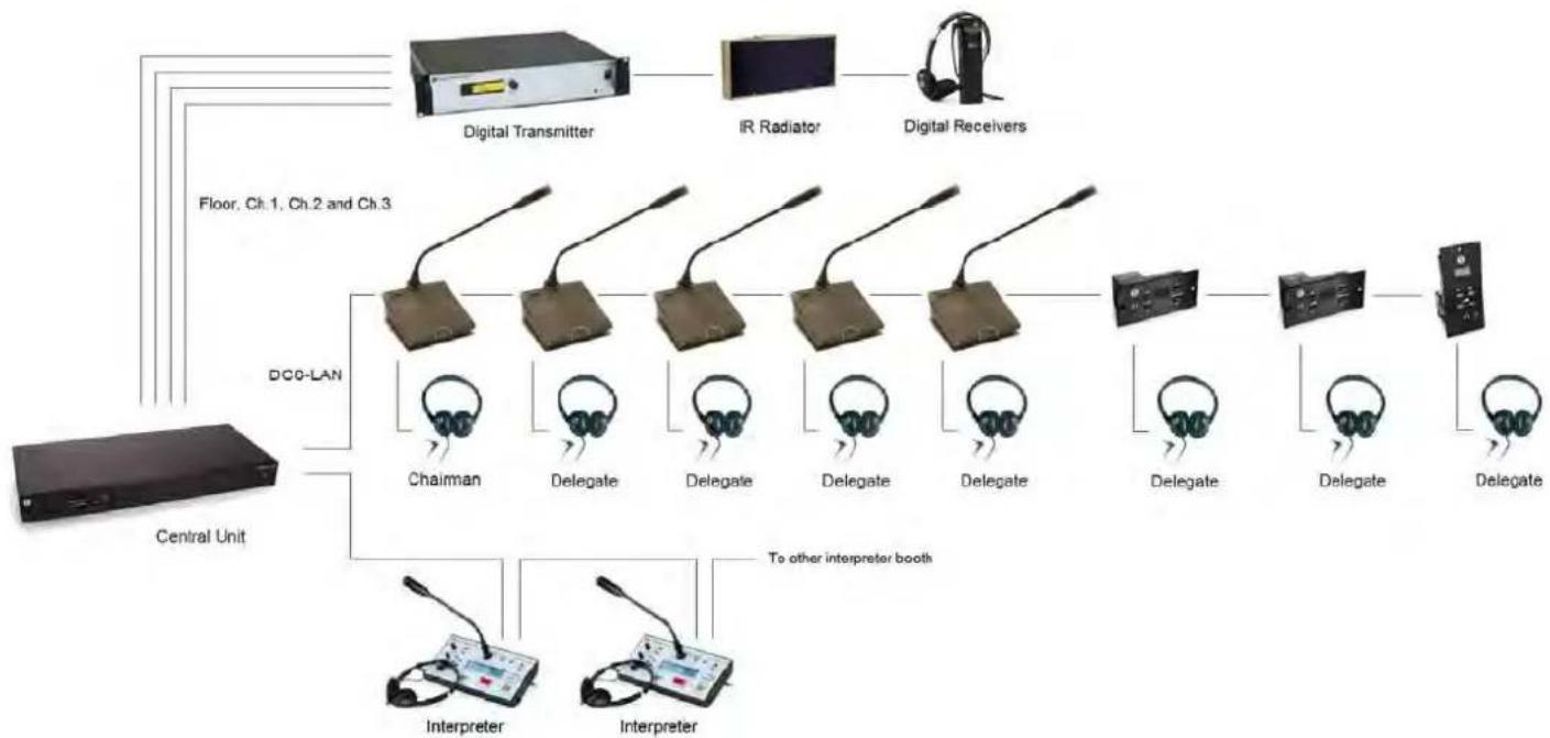
Typical schematics
flowchart
graph TD
    A["Central Unit"] --> B["DCO-LAN"]
    B --> C["Digital Transmitter"]
    B --> D["IR Radiator"]
    B --> E["Digital Receivers"]
    B --> F["Chairman"]
    B --> G["Delegate"]
    B --> H["Delegate"]
    B --> I["Delegate"]
    B --> J["Delegate"]
    B --> K["Delegate"]
    B --> L["Delegate"]
    B --> M["Delegate"]
    B --> N["Interpreter"]
    B --> O["Interpreter"]
    B --> P["To other interpreter booth"]
Technical Specifications
Digital Section
Sound quality ...... 20 bit audio @ 32 kHz sampling frequency
Analog Section
Frequency response 125-15kHz
Signal to noise ratio ....>85 dBA
Total harmonic distortion .... < 0.1%
Headphone output load 16-2k ohm
Max. Output level 1,2 V RMS
General
Factory selectable options
The following parameters are factory changeable:
- Channel wrap: Pressing the up-button when the highest channel is selected will also cause the channel number to wrap around if the 'Channel wrap parameter' is set
- Channel offset: Channel numbers can be from 0 to 31 or from 1 to 32 depending on the current system setting
• Volume step size - Show volume
• Volume/channel step initial/successive delay
Connectors
DCS-LAN network 2 pieces RJ45/8 pin
Analog outputs connector (front) .... 3,5 mm mini-jack
Analog outputs connector (back) 2 pin Molex
This connector is for professional use only
Max. System performance
Max. number of DM/CM (excl. CS) 3800
Max. number of IS 6xxx in one booth 32
Max. number of IS 6xxx 150
Max. number of AO 600x 20
Max. number of CS 6032 ...... practically unlimited
Max. number of languages 31
Max number of open microphones 8
General
Power requirement 24-48 V DC
Power consumption 0,5W
Power supplied from .... CU 61xx / EX 6010 / PS 600x
Temperature to guarantee specified performance
...... 5 Deg C. to 40 Deg C. (35 to 80% humidity)
Storage temperature
..... -20 Deg C. to 60 Deg C. (10 to 80% humidity)
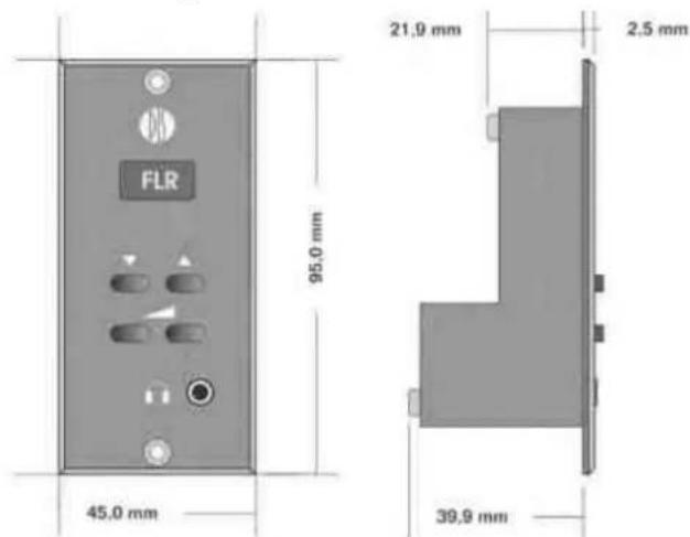
Dimensions (W x H x D) 45 (95) x 95 (45) x 40 mm
Dimensions in bracket are the horizontal version.
Accessories supplied .... User manual
- CS 6340 F Channel Selectors
- USER GUIDE
- Table of Contents
- Important
- Installation precautions
- Compliance
- Information to the user
- Cleaning
- Repacking
- Warranty
- Your DCS 6000 Conference System
- The DCS 6000 system
- System components
- Central equipment etc.
- Interpreter equipment
- Conference units and Ch. selectors
- Accessories
- Operating instructions
- CS 6340 Channel Selector
- General description
- Features
- User Controls, indications & connectors Front plate layout (CS 6340FV)
- Front plate controls
- Display
- Buttons (four)
- Connectors
- Headphone Connector (mini-jack)
- Headphone Connector (Molex)
- DCS-LAN connector
- Normal Operation
- Channel Selection
- Volume Control
- Storing local setup in FLASH
- Startup / Error conditions
- System Setup
- General guidelines
- Technical Specifications
- Digital Section
- Analog Section
- General
- Factory selectable options
- Max. System performance
- Connection Details
- DCS-LAN Chain
- Cat5e Connection Cables (AWG24)
Brand : SHURE
Model : CS 6340 FH
Category : Uncategorized